WO2023233485A1 - 無線品質予測システム、無線品質予測装置、無線品質予測方法、及びプログラム - Google Patents
無線品質予測システム、無線品質予測装置、無線品質予測方法、及びプログラム Download PDFInfo
- Publication number
- WO2023233485A1 WO2023233485A1 PCT/JP2022/021992 JP2022021992W WO2023233485A1 WO 2023233485 A1 WO2023233485 A1 WO 2023233485A1 JP 2022021992 W JP2022021992 W JP 2022021992W WO 2023233485 A1 WO2023233485 A1 WO 2023233485A1
- Authority
- WO
- WIPO (PCT)
- Prior art keywords
- wireless
- wireless terminal
- prediction
- terminal
- received power
- Prior art date
- Legal status (The legal status is an assumption and is not a legal conclusion. Google has not performed a legal analysis and makes no representation as to the accuracy of the status listed.)
- Ceased
Links
Images





Classifications
-
- G—PHYSICS
- G06—COMPUTING OR CALCULATING; COUNTING
- G06N—COMPUTING ARRANGEMENTS BASED ON SPECIFIC COMPUTATIONAL MODELS
- G06N20/00—Machine learning
-
- H—ELECTRICITY
- H04—ELECTRIC COMMUNICATION TECHNIQUE
- H04W—WIRELESS COMMUNICATION NETWORKS
- H04W24/00—Supervisory, monitoring or testing arrangements
- H04W24/04—Arrangements for maintaining operational condition
-
- H—ELECTRICITY
- H04—ELECTRIC COMMUNICATION TECHNIQUE
- H04W—WIRELESS COMMUNICATION NETWORKS
- H04W36/00—Hand-off or reselection arrangements
- H04W36/24—Reselection being triggered by specific parameters
- H04W36/30—Reselection being triggered by specific parameters by measured or perceived connection quality data
Definitions
- the present invention relates to a radio quality prediction system, a radio quality prediction device, a radio quality prediction method, and a program.
- a wireless quality prediction technology that predicts the wireless quality of a wireless terminal that performs wireless communication with a wireless base station. For example, a technique is known in which past quality information is accumulated in a wireless quality prediction server placed on a network, and a predicted value of wireless quality at a terminal location is calculated by machine learning (for example, see Non-Patent Document 1). .
- the method of predicting wireless quality is not limited to the above method, and various methods can be applied, such as predicting wireless quality using RNN (Recurrent Neural Networks) that performs time-series prediction from time-series information.
- RNN Recurrent Neural Networks
- the embodiments of the present invention have been made in view of the above-mentioned problems, and provide a wireless quality prediction system that improves the accuracy of predicting the wireless quality of wireless terminals in various communication environments.
- a wireless quality prediction system includes an information acquisition unit configured to acquire information about a wireless terminal that performs wireless communication, including the terminal location of the wireless terminal; a plurality of prediction units configured to predict a predicted value of received power of the wireless terminal after a predetermined period of time based on information of the wireless terminal, using mutually different prediction methods, and the plurality of prediction units calculation configured to weight the predicted value of the received power predicted by according to the terminal position of the wireless terminal to calculate predicted data regarding the radio quality of the wireless terminal after the predetermined time has elapsed. and a notification unit configured to notify the wireless terminal of the prediction data.
- FIG. 1 is a diagram illustrating an example of a system configuration of a wireless quality prediction system according to the present embodiment.
- FIG. 2 is a diagram for explaining an overview of processing of the wireless quality prediction system according to the present embodiment.
- 5 is a flowchart illustrating an example of wireless quality prediction processing according to the first embodiment.
- FIG. 3 is a diagram for explaining a wireless quality deterioration risk value according to the first embodiment.
- FIG. 7 is a diagram for explaining a method of calculating a risk value according to modification example 3; 7 is a flowchart illustrating an example of wireless quality prediction processing according to the second embodiment. 7 is a diagram for explaining an expected value of received power according to Example 2.
- FIG. 1 is a diagram illustrating an example of a hardware configuration of a wireless quality prediction device according to an embodiment.
- FIG. 2 is a diagram illustrating an example of the hardware configuration of a wireless terminal according to the present embodiment.
- FIG. 2 is a diagram illustrating an example of conventional wireless quality prediction processing.
- the wireless quality prediction technique is a technique for predicting the wireless quality of a wireless terminal that performs wireless communication with a wireless base station, for example, for stable use of wireless communication.
- FIG. 10 is a diagram illustrating an example of conventional wireless quality prediction processing. This figure shows an overview of the wireless quality prediction process disclosed in Non-Patent Document 1.
- the wireless quality prediction server 1 acquires performance data such as location information, radio field strength, and throughput from a plurality of wireless terminals 2 (step S1).
- the wireless quality prediction server 1 uses the acquired performance data to predict the radio field strength, throughput, etc. of the wireless terminals 2 and 3 based on the location information of the wireless terminals 2 and 3.
- a learning process for machine learning is executed (step S2).
- the wireless quality prediction server 1 accepts a wireless quality inquiry from, for example, a wireless terminal 3 having a mobile function such as a vehicle (step S3).
- the wireless quality prediction server 1 inputs the location information of the wireless terminal 3 included in the wireless quality inquiry into the trained neural network 10, thereby predicting the radio field strength, throughput, etc. of the wireless terminal 3.
- Inference processing for prediction is executed (step S4).
- the wireless quality prediction server 1 notifies the wireless terminal 3 of the predicted radio field strength of the wireless terminal 3 and the predicted values of wireless quality such as throughput (step S5).
- the wireless terminal 3 estimates the position of the wireless terminal 3 after the predetermined time and estimates the estimated position.
- a wireless quality inquiry including the following is sent to the wireless quality prediction server 1.
- the wireless terminal 3 can acquire wireless quality such as radio field strength and throughput of the wireless terminal 3 after a predetermined period of time has elapsed.
- the wireless quality prediction server 1 corresponds to the position information of the wireless terminal 3 using, for example, three-dimensional data such as a building DB (Database) or CAD (Computer Aided Design) data, and radio wave propagation estimation technology such as ray tracing. Received power (an example of wireless quality) may be predicted.
- three-dimensional data such as a building DB (Database) or CAD (Computer Aided Design) data
- CAD Computer Aided Design
- Received power an example of wireless quality
- the wireless quality prediction server 1 uses an RNN (Recurrent Neural Networks) etc. that performs time-series prediction from time-series data of the received power of the wireless terminal 3 (for example, received power for the last t seconds, etc.) to determine when a predetermined period of time has elapsed.
- the received power of the wireless terminal 3 later may be predicted.
- FIG. 11 is a diagram for explaining the problems of the prior art.
- the wireless quality prediction server 1 can predict the wireless quality (for example, received power) of the wireless terminal 2 after a predetermined period of time using various techniques.
- each method has a problem in that the accuracy of predicting wireless quality varies depending on the surrounding wireless environment.
- method A has a high radio quality prediction accuracy for a wireless terminal 3a that is indoors and has line-of-sight to the wireless base station 20a.
- method B may have higher radio quality prediction accuracy than method A.
- method C may have higher radio quality prediction accuracy than methods A and B.
- each method may not be suitable depending on the actual communication environment, and the prediction accuracy of each method varies depending on the communication environment.
- the wireless quality prediction system 100 has a system configuration as shown in FIG. 1, for example, in order to improve the prediction accuracy of the wireless quality of wireless terminals in various communication environments.
- FIG. 1 shows an example of a system configuration of a wireless quality prediction system according to this embodiment.
- the wireless quality prediction system 100 includes a wireless terminal 120 that can communicate with the wireless base station 101 through predetermined wireless communication 102, and a wireless quality prediction device 110 that predicts the wireless quality of the wireless terminal 120.
- the wireless quality prediction device 110 is, for example, an information processing device having a computer configuration or a system including multiple computers.
- the wireless quality prediction device 110 performs a wireless quality prediction process that predicts the wireless quality of the wireless terminal 120 after a predetermined period of time (n seconds) has elapsed based on wireless terminal information transmitted by the wireless terminal 120. Execute.
- the wireless terminal 120 is a wireless station that communicates with the wireless base station 101 using predetermined wireless communication, such as 5G (5th Generation) or LTE (Long Term Evolution).
- the wireless terminal 120 can communicate with the wireless quality prediction device 110 via, for example, the wireless base station 101.
- the wireless terminal 120 transmits information about the wireless terminal to the wireless quality prediction device 110, requests a predicted value of wireless quality after a predetermined period of time, and receives the predicted value of wireless quality notified from the wireless quality prediction device 110. Based on this, predetermined control such as handover is performed.
- the wireless terminal 120 may be, for example, a wireless station such as a smartphone owned by a user, or may be a wireless station with a mobile function such as a robot or a vehicle. .
- the wireless terminal 120 has, for example, a position acquisition unit 121, a position estimation unit 122, a state acquisition unit 123, a received power acquisition unit 124, an inquiry unit 125, and a control determination unit by executing a predetermined program by a computer included in the wireless terminal 120. 126, a terminal control section 127, a wireless communication section 128, and the like. Note that at least some of the above functional configurations may be realized by hardware.
- the position acquisition unit 121 acquires the terminal position (current position) of the wireless terminal 120, for example, using a positioning device such as a GPS (Global Positioning System) device included in the wireless terminal 120.
- a positioning device such as a GPS (Global Positioning System) device included in the wireless terminal 120.
- the position estimating unit 122 calculates the position of the wireless terminal 120 after a predetermined period of time based on the terminal position of the wireless terminal 120 acquired by the position acquiring unit 121 and the movement of the wireless terminal 120 measured by a sensor such as an acceleration sensor or an angle sensor. The terminal position (estimated position) of the wireless terminal 120 (after n seconds) is calculated. Alternatively, the position estimating unit 122 stores the history of the current position of the wireless terminal 120 acquired by the position acquiring unit 121, and based on this history, calculates the terminal position (estimated) of the wireless terminal 120 after a predetermined time has elapsed. location) may be estimated. Further, when the wireless terminal 120 is a robot, a vehicle, etc. that moves along a predetermined movement route, the position estimating unit 122 determines the location after a predetermined period of time based on the movement route information of the wireless terminal 120, for example. The terminal position (estimated position) of the wireless terminal 120 may be estimated.
- the status acquisition unit 123 acquires the terminal status (direction, speed, etc.) of the wireless terminal 120 based on sensor data such as an acceleration sensor and an angle sensor included in the wireless terminal 120, for example. Furthermore, the state acquisition unit 123 estimates the terminal state of the wireless terminal 120 after a predetermined time (n seconds) has elapsed based on sensor data such as an acceleration sensor and an angle sensor. For example, the state acquisition unit 123 uses the sensor data of the wireless terminal 120 as a feature amount and the terminal state of the wireless terminal 120 after n seconds as teacher data, using a machine learning model that has been previously learned to determine the state of the wireless terminal after n seconds. 120 terminal states may be estimated. Alternatively, the status acquisition unit 123 may store the acquired history of the terminal status of the wireless terminal 120, and estimate the terminal status of the wireless terminal after a predetermined time has elapsed based on this history.
- the received power acquisition unit 124 acquires information on the received power of the wireless terminal 120 that performs wireless communication with the wireless base station 101.
- the received power information for example, information such as RSSI (Received Signal Strength Indicator) outputted by the wireless communication unit 128 can be applied.
- the received power acquisition unit 124 acquires received data (time series data) of the wireless terminal 120 for the most recent t seconds.
- the inquiry unit 125 receives the terminal position (current position and estimated position) of the wireless terminal 120 described above, estimated value of the terminal state (direction, speed, etc.) of the wireless terminal 120 after a predetermined time has elapsed, and the received information.
- Information about the wireless terminal including information such as power is transmitted to the wireless quality prediction device 110.
- the terminal position of the wireless terminal includes, for example, the terminal position (current position) of the wireless terminal 120 acquired by the position acquisition unit 121, and after a predetermined time estimated by the position estimation unit 122 (n seconds later).
- the terminal position (estimated position) of the wireless terminal 120 is included.
- the received power includes, for example, the latest received power acquired by the received power acquisition unit 124 and the received power for the most recent t seconds (time series data).
- the control determining unit 126 receives the predicted value of wireless quality transmitted from the wireless quality prediction device 110 according to the information of the wireless terminal transmitted by the inquiry unit 125, and determines the wireless quality based on the received predicted value of wireless quality.
- the content of control of the terminal 120 is determined. For example, the control determining unit 126 determines whether or not the wireless terminal 120 will start handover based on the predicted value of the wireless quality after a predetermined time (n seconds), which is received from the wireless quality prediction device 110. to decide.
- the control determination unit 126 It is also possible to determine whether to change the moving route or the like based on the predicted value of the wireless quality.
- the terminal control unit 127 controls the entire wireless terminal 120. For example, the terminal control unit 127 starts handover of the wireless terminal 12, changes the movement route, etc. based on the determination result by the control determination unit 126.
- the wireless communication unit 128 performs predetermined wireless communication with the wireless base station 101, for example, under control from the terminal control unit 127. Furthermore, the wireless communication unit 128 executes, for example, a handover process to change the wireless base station 101 to which the wireless communication unit 101 is connected, under control from the terminal control unit 127.
- the wireless quality prediction device 110 has, for example, an information acquisition unit 111, a plurality of prediction units 112a, 112b, 112c, .
- a calculation unit 113, a notification unit 114, a storage unit 115, etc. are implemented.
- "prediction unit 112" is used to refer to any prediction unit among the plurality of prediction units 112a, 112b, 112c, . . . .
- the information acquisition unit 111 executes an information acquisition process to acquire information about the wireless terminal transmitted by the inquiry unit 125 of the wireless terminal 120 that performs wireless communication with the wireless base station 101. Further, the information acquisition unit 111 notifies the plurality of prediction units 112 of the acquired wireless terminal information, and also notifies the calculation unit 113 of received power information.
- the calculation unit 113 weights the predicted values of received power predicted by the plurality of prediction units 112a, 112b, 112c, . 120 is executed to calculate predicted data regarding radio quality. For example, the calculation unit 113 uses a deterioration risk value (the communication quality becomes below a threshold probability). Alternatively, the calculation unit 113 uses a value indicating the communication quality of the wireless terminal 120 after a predetermined period of time (for example, a predicted value of received power, a predicted value of throughput, etc.) as predicted data regarding the wireless quality of the wireless terminal 120. may be calculated.
- the notification unit 114 notifies (sends) the predicted data regarding the wireless quality of the wireless terminal 120 calculated by the calculation unit 113 to the wireless terminal 120 that transmitted the wireless terminal information.
- the storage unit 115 is realized by, for example, a program executed by a computer included in the wireless quality prediction device 110, a storage device, a memory, and the like.
- the storage unit 115 stores, for example, a threshold value for the calculation unit 113 to determine the deterioration of wireless quality.
- the storage unit 115 stores a plurality of threshold values that are preset according to, for example, the purpose of use, the model of the wireless terminal 120, the location, and the like.
- the functional configuration of the wireless quality prediction device 110 described in FIG. 1 is an example.
- at least some of the plurality of prediction units 112a, 112b, 112c, . . . may be realized by a computer or the like external to the wireless quality prediction device 110.
- the storage unit 115 may use a computer external to the wireless quality prediction device 110, a cloud service, or the like.
- at least some of the plurality of prediction units 112 and calculation units 113 may be included in the wireless terminal 120.
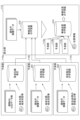
- FIG. 2 is a diagram for explaining an overview of the processing of the wireless quality prediction system according to the present embodiment.
- the prediction unit 112a uses, for example, radio wave propagation estimation such as ray tracing from three-dimensional data such as a building DB and CAD data, and information such as the terminal position and terminal state of the wireless terminal 120. , predict the received power of the wireless terminal 120.
- the prediction unit 112a calculates a predicted value of the received power of the wireless terminal 120 after a predetermined time has elapsed, based on the terminal position and terminal information of the wireless terminal 120 after the elapse of a predetermined time (n seconds). can do.
- the prediction unit 112a may be one that predicts the received power of the wireless terminal 120 based on three-dimensional data and the terminal position of the wireless terminal 120, regardless of the terminal state of the wireless terminal 120.
- the prediction unit 112b performs machine learning to output a predicted value of the received power of the wireless terminal 120 based on the terminal position and terminal state of the wireless terminal 120 from past performance data and the like. It has a container 201. For example, the prediction unit 112b predicts the predicted value of the received power of the wireless terminal 120 after a predetermined time has elapsed, based on the terminal position and terminal information of the wireless terminal 120 after the elapse of a predetermined time (n seconds). can do. Note that the prediction unit 112b may predict the received power of the wireless terminal 120 based on the terminal position of the wireless terminal 120, without depending on the terminal state of the wireless terminal 120.
- the prediction unit 112a and the prediction unit 112b are configured to use a terminal position of the wireless terminal 120 after a predetermined time to predict the received power of the wireless terminal 120 after a predetermined time has elapsed. This is an example of the prediction part.
- the prediction unit 112c calculates a predicted value of the received power of the wireless terminal 120 after a predetermined period of time based on the terminal position of the wireless terminal 120, the received power for the most recent t seconds, etc. from past performance data, etc.
- the received power learning device 202 is machine-trained to output the received power.
- the prediction unit 112c predicts the received power of the wireless terminal 120 after a predetermined period of time based on the terminal position of the wireless terminal 120 and the received power (time series data) for the most recent t seconds of the wireless terminal 120. Predicted values can be predicted.
- the prediction unit 112c is configured to predict the received power of the wireless terminal 120 after a predetermined period of time using the terminal position of the wireless terminal 120 and the time series data of the received power of the wireless terminal 120. This is an example of the second prediction unit.
- the calculation unit 113 uses the received power of the wireless terminal 120 predicted by the plurality of prediction units 112 at the plurality of terminal positions and the correct value of the received power at the plurality of terminal positions to calculate the plurality of reception powers at each terminal position. It has a wireless quality learning device 210 that has learned the weights of the prediction unit 112. For example, the calculation unit 113 predicts the terminal position of the wireless terminal 120 after a predetermined time (n seconds) and the received power of the wireless terminal 120 after the predetermined time predicted by the plurality of prediction units 112. Based on this value, a predicted value of wireless quality after a predetermined period of time can be calculated.
- FIG. 3 is a flowchart illustrating an example of wireless quality prediction processing according to the first embodiment. This process shows a specific example of the process explained in FIG. It is assumed that at the start of the process shown in FIG. 3, the received power learning device 201, the received power learning device 202, and the wireless quality learning device 210 described in FIG. 2 have already been trained.
- the information acquisition unit 111 of the wireless quality prediction device 110 acquires the wireless terminal information transmitted by the wireless terminal 120.
- the wireless terminal information includes the terminal position (current position and estimated position) of the wireless terminal 120, and the estimated terminal state (direction, speed, etc.) of the wireless terminal 120 after a predetermined time (n seconds) has elapsed. It is assumed that information such as the value and the received power of the wireless terminal 120 is included. Further, it is assumed that the information on the received power of the wireless terminal 120 includes information on the received power of the wireless terminal 120 for the most recent t seconds (time series data). Note that the values such as "n seconds" and "t seconds" are set to appropriate values in advance by, for example, an administrator who manages the wireless quality prediction system 100 or a designer who designed the wireless quality prediction system 100. It is assumed that
- step S302 the prediction unit 112a of the wireless quality prediction device 110 performs the radio wave propagation estimation described above using the estimated values of the terminal position and terminal state of the wireless terminal 120 after a predetermined period of time (n seconds) has elapsed. , predicts the received power of the wireless terminal 120 after a predetermined period of time has elapsed.
- step S303 the prediction unit 112b of the wireless quality prediction device 110 uses the estimated values of the terminal position and terminal state of the wireless terminal 120 after a predetermined period of time (n seconds) to estimate the received power learning device 201. Accordingly, the received power of the wireless terminal 120 after a predetermined time has elapsed is predicted.
- step S304 the prediction unit 112c of the wireless quality prediction device 110 uses the terminal position (current position) of the wireless terminal 120 and the received power of the wireless terminal 120 for the most recent t seconds to calculate the received power learning device 202. , predicts the received power of the wireless terminal 120 after a predetermined period of time has elapsed.
- the received power of the wireless terminal 120 for the most recent t seconds includes, for example, time-series data of the received power measured by the wireless terminal 120 at predetermined time intervals.
- the processes in steps S302 to S304 are executed, for example, in parallel by the prediction units 112a to 112c.
- step S305 the calculation unit 113 of the wireless quality prediction device 110 weights the predicted values of the received power predicted by the plurality of prediction units 112a to 112c with a weight according to the terminal position of the wireless terminal 120, and calculates the predicted values for a predetermined period of time. Calculate the wireless quality deterioration risk value after the elapse of.
- FIG. 4 is a diagram for explaining the wireless quality deterioration risk value according to the first embodiment.
- a wireless terminal 120 that performs wireless communication with the wireless base station 101 moves from its current position to an estimated position after a predetermined period of time (n seconds) has elapsed.
- the prediction unit 112a predicts that the predicted value of the received power of the wireless terminal 120 at the estimated position after a predetermined time has elapsed is -82 dBm.
- the prediction unit 112b predicts the predicted value of the received power of the wireless terminal 120 at the estimated position to be -77 dBm
- the predicted unit 112c predicts the predicted value of the received power of the wireless terminal 120 at the estimated position to be -80 dBm. shall be taken as a thing.
- the calculation unit 113 uses the actual measured value of the received power of the wireless terminal 120 "-80 dBm" and the predicted values of the plurality of prediction units 112a to 112c. , learn the weights of each predictor. For example, the calculation unit 113 trains the wireless quality learning device 210 so that the weight of the prediction unit 112 whose predicted value at the estimated position is closer to the measured value is higher.
- the calculation unit 113 learns the wireless quality learning device 210 by repeatedly performing similar processing.
- the terminal position and estimated position of the wireless terminal 120 may be a pinpoint, or may be, for example, a 5 m square cell.
- data other than location may be used as the feature amount used for learning (for example, environmental information acquired by LiDAR, or the location of another terminal, etc.).
- the calculation unit 113 uses the learned weights to calculate a wireless quality deterioration risk value.
- the weights after learning of the prediction units 112a, 112b, and 112c are 2:1:3.
- step S306 the notification unit 114 of the wireless quality prediction device 110 notifies (sends) the wireless quality deterioration risk value predicted by the calculation unit 113 to the wireless terminal 120.
- the wireless terminal 120 executes predetermined control, such as handover or route change, based on the wireless quality deterioration risk value notified from the wireless quality prediction device 110. For example, if the wireless quality deterioration risk value is equal to or greater than a predetermined value, the control determining unit 126 of the wireless terminal 120 determines to start handover to another wireless base station, and instructs the terminal controller 127 to start the handover. do. Further, the terminal control unit 127 controls the wireless communication unit 128 according to instructions from the control determination unit 126 to start handover.
- predetermined control such as handover or route change
- the wireless quality prediction system 100 weights the plurality of prediction units 112 based on the terminal position of the wireless terminal 120, thereby achieving prediction accuracy of the wireless quality deterioration risk value in various communication environments. can be improved.
- the calculation unit 113 may calculate the wireless quality deterioration risk value using a method other than the weighting described above. For example, the calculation unit 113 uses a method similar to that used for machine learning classification (for example, "Naive Bayes", etc.), and uses the predicted values and position information from each prediction unit 112 as feature quantities, and uses You can predict risk by finding the probability that Alternatively, the calculation unit 113 may calculate the probability that the predicted value from each prediction unit 112 is correct, and make a total risk prediction.
- machine learning classification for example, "Naive Bayes", etc.
- the calculation unit 113 adopts the lowest predicted value among the predicted values from each prediction unit 112 for each terminal position (or estimated position), and determines whether the adopted predicted value is equal to or less than a threshold value. You can judge. Alternatively, the calculation unit 113 may use machine learning or the like to find the probability that the lowest predicted value itself is correct, and use the probability as the risk value.
- each prediction unit 112 predicts a uniquely determined prediction value, but each prediction unit 112 predicts a probability distribution 501 of received power as shown in FIG. 5, for example. It may be calculated.
- the calculation unit 113 weights the probabilities for the received power values from each prediction unit 112 so that the probability distribution calculated by each prediction unit 112 becomes a joint probability distribution, and so that the total sum becomes 1. Then, a probability distribution 502 of weighted received power is created.
- the calculation unit 113 calculates a wireless quality deterioration risk value using the weighted probability distribution 502 of received power. For example, if the required quality (threshold) is -70 dBm or more, the sum of the probability distributions of less than -70 dBm, "0.6", becomes the risk value.
- the wireless quality prediction device 110 uses a deterioration risk value (a deterioration risk value indicating the risk that the communication quality of the wireless terminal 120 will deteriorate below a threshold value) after a predetermined time has elapsed as a predicted value of the wireless quality. The probability of that happening was calculated.
- the wireless quality prediction device 110 calculates an expected value (for example, an expected value of received power, an expected value of throughput, etc.) indicating the wireless quality of the wireless terminal 120 after a predetermined period of time has elapsed. You may.
- FIG. 6 is a flowchart illustrating an example of wireless quality prediction processing according to the second embodiment. Note that among the processes shown in FIG. 6, the processes in steps S301 to S304 are the same as the wireless quality prediction process according to the first embodiment described in FIG. 3, so the description thereof will be omitted here.
- step S601 the calculation unit 113 of the wireless quality prediction device 110 weights the predicted values of received power predicted by the plurality of prediction units 112 with a weight according to the terminal position of the wireless terminal 120, and after a predetermined time elapses.
- the expected value of the received power of the wireless terminal 120 (after n seconds) is calculated.
- FIG. 7 is a diagram for explaining the expected value of received power according to the second embodiment.
- the predicted value of the received power predicted by the prediction unit 112a is ⁇ 82 dBm
- the weight of the prediction unit 112a is 2.
- the predicted value of the received power predicted by the prediction unit 112b is ⁇ 77 dBm
- the weight of the prediction unit 112b is 1.
- the predicted value of the received power predicted by the prediction unit 112c is ⁇ 80 dBm, and the weight of the prediction unit 112c is 3.
- the calculation unit 113 calculates the expected value E of the received power of the wireless terminal 120 after a predetermined time (n seconds) has elapsed using (Equation 1) in FIG.
- the expected value E of the received power of the wireless terminal 120 after a predetermined time (n seconds) has passed is ⁇ 80.2 dBm.
- step S602 the notification unit 114 of the wireless quality prediction device 110 notifies the wireless terminal 120 of the expected value of the received power of the wireless terminal 120 after the predetermined time period calculated by the calculation unit 113.
- step S603 the wireless terminal 120 executes predetermined control, such as handover or route change, based on the expected value of received power notified from the wireless quality prediction device 110.
- the wireless quality prediction system 100 improves the prediction accuracy of the wireless quality deterioration risk value in various communication environments by weighting the plurality of prediction units 112 according to the terminal position of the wireless terminal 120. can be done.
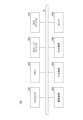
- FIG. 8 is a diagram showing an example of the hardware configuration of the wireless quality prediction device 110 according to the present embodiment.
- the wireless quality prediction device 110 includes, for example, the configuration of a computer 800 as shown in FIG. 8.
- the computer 800 includes a processor 801, a memory 802, a storage device 803, a communication device 804, an input device 805, an output device 806, a bus B, and the like.
- the processor 801 is, for example, an arithmetic device such as a CPU (Central Processing Unit) that implements various functions by executing a predetermined program.
- the memory 802 is a storage medium readable by the computer 800, and includes, for example, RAM (Random Access Memory), ROM (Read Only Memory), and the like.
- the storage device 803 is a computer-readable storage medium, and may include, for example, an HDD (Hard Disk Drive), an SSD (Solid State Drive), various optical disks, magneto-optical disks, and the like.
- the communication device 804 includes one or more hardware (communication devices) for communicating with other devices via a wireless or wired network.
- the input device 805 is an input device (eg, keyboard, mouse, microphone, switch, button, sensor, etc.) that accepts input from the outside.
- the output device 806 is an output device (for example, a display, a speaker, an LED lamp, etc.) that performs output to the outside. Note that the input device 805 and the output device 806 may have an integrated configuration (for example, an input/output device such as a touch panel display).
- Bus B is commonly connected to each of the above components, and transmits, for example, address signals, data signals, and various control signals.
- the processor 801 is not limited to a CPU, and may be, for example, a DSP (Digital Signal Processor), a PLD (Programmable Logic Device), or an FPGA (Field Programmable Gate Array).
- FIG. 9 is a diagram showing an example of the hardware configuration of the wireless terminal according to the present embodiment.
- the wireless terminal 120 includes, for example, a GPS device 901, a sensor 902, and the like.
- the GPS device 901 is a positioning device that receives positioning signals transmitted by GPS satellites and outputs position information indicating the position of the wireless terminal 120.
- the sensor 902 is a device that detects the movement of the wireless terminal 120, such as an acceleration sensor, an angle sensor, or an IMU (Inertial Measurement Unit).
- the wireless quality prediction device 110 and the wireless terminal 120 in this embodiment are not limited to being implemented by dedicated devices, but may be implemented by a general-purpose computer. In that case, a program for realizing this function may be recorded on a computer-readable recording medium, and the program recorded on the recording medium may be read into a computer system and executed.
- the "computer system” herein includes hardware such as an OS and peripheral devices.
- computer-readable recording medium includes various storage devices such as flexible disks, magneto-optical disks, ROMs, CD-ROMs, and other portable media, and hard disks built into computer systems.
- a “computer-readable recording medium” refers to a storage medium that dynamically stores a program for a short period of time, such as a communication line when transmitting a program via a network such as the Internet or a communication line such as a telephone line. It may also include a device that retains a program for a certain period of time, such as a volatile memory inside a computer system that is a server or client in that case.
- the above-mentioned program may be one for realizing a part of the above-mentioned functions, and further may be one that can realize the above-mentioned functions in combination with a program already recorded in the computer system. It may be realized using hardware such as a PLD (Programmable Logic Device) or an FPGA (Field Programmable Gate Array).
- PLD Programmable Logic Device
- FPGA Field Programmable Gate Array
- the wireless quality prediction system 100 can use a plurality of prediction techniques to improve the prediction accuracy of wireless quality compared to prediction using only a single prediction technique.
- the wireless terminal 120 can perform controls such as switching the wireless base station 101 to which it is connected, controlling communication parameters, or changing the movement route, and can stably use wireless communication and applications.
- This specification discloses at least a radio quality prediction system, a radio quality prediction device, a radio quality prediction method, and a program as described below.
- (Section 1) an information acquisition unit configured to acquire information about the wireless terminal including the terminal location of the wireless terminal that performs wireless communication; a plurality of prediction units configured to predict, based on information on the wireless terminal, predicted values of received power of the wireless terminal after a predetermined period of time using mutually different prediction methods; The predicted values of the received power predicted by the plurality of prediction units are weighted according to the terminal position of the wireless terminal to calculate predicted data regarding the wireless quality of the wireless terminal after the predetermined time has elapsed.
- the calculation unit is A learning device that learns weights according to each terminal position using predicted values of the received power predicted by the plurality of prediction units at the plurality of terminal positions and correct values of the reception power at the plurality of terminal positions.
- the wireless quality prediction system according to item 1 or 2.
- the information on the wireless terminal includes the terminal position of the wireless terminal after the predetermined time has elapsed,
- the plurality of prediction units are configured to predict received power of the wireless terminal after the predetermined time has elapsed, using a terminal position of the wireless terminal after the predetermined time has elapsed. having a prediction section;
- the wireless quality prediction system according to item 1 or 2.
- the information on the wireless terminal includes time-series data of received power of the wireless terminal,
- the plurality of prediction units are configured to predict the received power of the wireless terminal after the predetermined time has elapsed, using the terminal position of the wireless terminal and the time series data of the received power. including a prediction section, The wireless quality prediction system according to item 4.
- an information acquisition unit configured to acquire information about the wireless terminal including the terminal location of the wireless terminal that performs wireless communication; a plurality of prediction units configured to predict, based on information on the wireless terminal, predicted values of received power of the wireless terminal after a predetermined period of time using mutually different prediction methods; The predicted values of the received power predicted by the plurality of prediction units are weighted according to the terminal position of the wireless terminal to calculate predicted data regarding the wireless quality of the wireless terminal after the predetermined time has elapsed.
- a wireless quality prediction device having: (Section 7) Wireless quality prediction system A process of acquiring information about the wireless terminal including the terminal location of the wireless terminal that performs wireless communication; A process of predicting a predicted value of received power of the wireless terminal after a predetermined period of time based on information of the wireless terminal using a plurality of mutually different prediction methods; A process of weighting the predicted value of the received power predicted by the plurality of prediction methods according to the terminal position of the wireless terminal to calculate predicted data regarding the wireless quality of the wireless terminal after the predetermined time has elapsed. and, a process of notifying the wireless terminal of the prediction data; A wireless quality prediction method that performs (Section 8) A program that causes a computer to execute the wireless quality prediction method according to item 7.
- Radio Quality Prediction System 110 Radio Quality Prediction Device 111 Information Acquisition Unit 112 Prediction Unit 112a Prediction Unit (Example of First Prediction Unit) 112b prediction unit (an example of the first prediction unit) 112c prediction unit (second prediction unit) 113 Calculation unit 114 Notification unit 120 Wireless terminal 210 Wireless quality learning device (learning device)
Landscapes
- Engineering & Computer Science (AREA)
- Software Systems (AREA)
- Computer Networks & Wireless Communication (AREA)
- Signal Processing (AREA)
- Theoretical Computer Science (AREA)
- Computer Vision & Pattern Recognition (AREA)
- Evolutionary Computation (AREA)
- Medical Informatics (AREA)
- Data Mining & Analysis (AREA)
- Physics & Mathematics (AREA)
- Computing Systems (AREA)
- General Engineering & Computer Science (AREA)
- General Physics & Mathematics (AREA)
- Mathematical Physics (AREA)
- Artificial Intelligence (AREA)
- Mobile Radio Communication Systems (AREA)
Priority Applications (2)
| Application Number | Priority Date | Filing Date | Title |
|---|---|---|---|
| JP2024524546A JP7779385B2 (ja) | 2022-05-30 | 2022-05-30 | 無線品質予測システム、無線品質予測装置、無線品質予測方法、及びプログラム |
| PCT/JP2022/021992 WO2023233485A1 (ja) | 2022-05-30 | 2022-05-30 | 無線品質予測システム、無線品質予測装置、無線品質予測方法、及びプログラム |
Applications Claiming Priority (1)
| Application Number | Priority Date | Filing Date | Title |
|---|---|---|---|
| PCT/JP2022/021992 WO2023233485A1 (ja) | 2022-05-30 | 2022-05-30 | 無線品質予測システム、無線品質予測装置、無線品質予測方法、及びプログラム |
Publications (1)
| Publication Number | Publication Date |
|---|---|
| WO2023233485A1 true WO2023233485A1 (ja) | 2023-12-07 |
Family
ID=89025898
Family Applications (1)
| Application Number | Title | Priority Date | Filing Date |
|---|---|---|---|
| PCT/JP2022/021992 Ceased WO2023233485A1 (ja) | 2022-05-30 | 2022-05-30 | 無線品質予測システム、無線品質予測装置、無線品質予測方法、及びプログラム |
Country Status (2)
| Country | Link |
|---|---|
| JP (1) | JP7779385B2 (https=) |
| WO (1) | WO2023233485A1 (https=) |
Citations (4)
| Publication number | Priority date | Publication date | Assignee | Title |
|---|---|---|---|---|
| JP2004112482A (ja) * | 2002-09-19 | 2004-04-08 | Nippon Telegr & Teleph Corp <Ntt> | 位置検出方法及びシステム及び無線通信装置 |
| JP2009278421A (ja) * | 2008-05-15 | 2009-11-26 | Nec Corp | 無線品質劣化予測システム |
| WO2021171341A1 (ja) * | 2020-02-25 | 2021-09-02 | 日本電信電話株式会社 | 通信品質を予測するシステム、装置、方法及びプログラム |
| WO2022097270A1 (ja) * | 2020-11-06 | 2022-05-12 | 日本電信電話株式会社 | 学習方法、無線品質推定方法、学習装置、無線品質推定装置、及びプログラム |
-
2022
- 2022-05-30 WO PCT/JP2022/021992 patent/WO2023233485A1/ja not_active Ceased
- 2022-05-30 JP JP2024524546A patent/JP7779385B2/ja active Active
Patent Citations (4)
| Publication number | Priority date | Publication date | Assignee | Title |
|---|---|---|---|---|
| JP2004112482A (ja) * | 2002-09-19 | 2004-04-08 | Nippon Telegr & Teleph Corp <Ntt> | 位置検出方法及びシステム及び無線通信装置 |
| JP2009278421A (ja) * | 2008-05-15 | 2009-11-26 | Nec Corp | 無線品質劣化予測システム |
| WO2021171341A1 (ja) * | 2020-02-25 | 2021-09-02 | 日本電信電話株式会社 | 通信品質を予測するシステム、装置、方法及びプログラム |
| WO2022097270A1 (ja) * | 2020-11-06 | 2022-05-12 | 日本電信電話株式会社 | 学習方法、無線品質推定方法、学習装置、無線品質推定装置、及びプログラム |
Also Published As
| Publication number | Publication date |
|---|---|
| JP7779385B2 (ja) | 2025-12-03 |
| JPWO2023233485A1 (https=) | 2023-12-07 |
Similar Documents
| Publication | Publication Date | Title |
|---|---|---|
| CN104995973B (zh) | 移动设备定位系统 | |
| EP3008929B1 (en) | Detecting geo-fence events using varying confidence levels | |
| KR101787929B1 (ko) | 모바일 사용자의 위치를 예측하는 방법 및 디바이스 | |
| US8731537B2 (en) | Wireless communication devices in which operating context is used to reduce operating cost and methods for operating same | |
| US12250658B2 (en) | Utilizing machine learning models to estimate user device spatiotemporal behavior | |
| JP2016531277A (ja) | ジオフェンスを検出するための低減電力位置判定 | |
| JP7729400B2 (ja) | 無線品質予測方法、及び無線通信システム | |
| KR101837709B1 (ko) | 위치 제공자 프로세스들을 실행 | |
| US20170272910A1 (en) | Automatic optimization procedure termination using a smoothing-based technique | |
| JP2013197704A (ja) | トラフィック量予測処理装置およびコンピュータプログラム | |
| WO2020091590A1 (en) | A system and method for locating a device in an indoor environment | |
| CN112673367A (zh) | 用于预测用户意图的电子设备和方法 | |
| JP7779385B2 (ja) | 無線品質予測システム、無線品質予測装置、無線品質予測方法、及びプログラム | |
| Langpoklakpam et al. | Localization of victims in disaster area using RSSI with machine learning techniques | |
| CN118646655B (zh) | 基于社交网络的节点通信方法、装置、介质及设备 | |
| JP7841613B2 (ja) | 推定装置、学習装置、推定方法、学習方法、及びプログラム | |
| Liu et al. | Edge big data-enabled low-cost indoor localization based on Bayesian analysis of RSS | |
| CN112783992A (zh) | 一种基于兴趣点的地图功能区域确定方法和装置 | |
| JP7800677B2 (ja) | 無線品質予測装置、無線品質予測方法、及びプログラム | |
| US20250337510A1 (en) | Received signal power prediction system, received signal power prediction apparatus, received signal power prediction method, and program | |
| JP7412380B2 (ja) | 特徴量データ生成装置、無線利用予測システム、特徴量データ生成方法及びコンピュータプログラム | |
| WO2024089820A1 (ja) | 情報配信装置、予測システム、情報配信方法、及びプログラム | |
| US20250343744A1 (en) | Systems and methods for location accuracy estimation over a wireless network | |
| EP4439404A1 (en) | Search path determining system and method | |
| WO2025150115A1 (ja) | 無線通信装置及び無線通信方法 |
Legal Events
| Date | Code | Title | Description |
|---|---|---|---|
| 121 | Ep: the epo has been informed by wipo that ep was designated in this application |
Ref document number: 22944774 Country of ref document: EP Kind code of ref document: A1 |
|
| WWE | Wipo information: entry into national phase |
Ref document number: 2024524546 Country of ref document: JP |
|
| NENP | Non-entry into the national phase |
Ref country code: DE |
|
| 122 | Ep: pct application non-entry in european phase |
Ref document number: 22944774 Country of ref document: EP Kind code of ref document: A1 |