WO2023233479A1 - Liquefied gas transfer piping system - Google Patents
Liquefied gas transfer piping system Download PDFInfo
- Publication number
- WO2023233479A1 WO2023233479A1 PCT/JP2022/021982 JP2022021982W WO2023233479A1 WO 2023233479 A1 WO2023233479 A1 WO 2023233479A1 JP 2022021982 W JP2022021982 W JP 2022021982W WO 2023233479 A1 WO2023233479 A1 WO 2023233479A1
- Authority
- WO
- WIPO (PCT)
- Prior art keywords
- liquefied gas
- piping system
- pipe
- cover
- gas transfer
- Prior art date
Links
- 238000012546 transfer Methods 0.000 title claims abstract description 31
- 239000007789 gas Substances 0.000 claims description 105
- 239000011261 inert gas Substances 0.000 claims description 64
- 238000001514 detection method Methods 0.000 claims description 13
- 231100001261 hazardous Toxicity 0.000 claims description 7
- 230000032258 transport Effects 0.000 claims description 4
- IJGRMHOSHXDMSA-UHFFFAOYSA-N Atomic nitrogen Chemical compound N#N IJGRMHOSHXDMSA-UHFFFAOYSA-N 0.000 description 11
- 238000007789 sealing Methods 0.000 description 11
- 239000012530 fluid Substances 0.000 description 8
- 229910001873 dinitrogen Inorganic materials 0.000 description 7
- QVGXLLKOCUKJST-UHFFFAOYSA-N atomic oxygen Chemical compound [O] QVGXLLKOCUKJST-UHFFFAOYSA-N 0.000 description 6
- 239000001257 hydrogen Substances 0.000 description 6
- 229910052739 hydrogen Inorganic materials 0.000 description 6
- 239000001301 oxygen Substances 0.000 description 6
- 229910052760 oxygen Inorganic materials 0.000 description 6
- CURLTUGMZLYLDI-UHFFFAOYSA-N Carbon dioxide Chemical compound O=C=O CURLTUGMZLYLDI-UHFFFAOYSA-N 0.000 description 4
- UFHFLCQGNIYNRP-UHFFFAOYSA-N Hydrogen Chemical compound [H][H] UFHFLCQGNIYNRP-UHFFFAOYSA-N 0.000 description 4
- 239000013013 elastic material Substances 0.000 description 4
- 238000012545 processing Methods 0.000 description 4
- 238000010586 diagram Methods 0.000 description 3
- 238000009413 insulation Methods 0.000 description 3
- 239000003949 liquefied natural gas Substances 0.000 description 3
- 239000000463 material Substances 0.000 description 3
- QGZKDVFQNNGYKY-UHFFFAOYSA-N Ammonia Chemical compound N QGZKDVFQNNGYKY-UHFFFAOYSA-N 0.000 description 2
- XKRFYHLGVUSROY-UHFFFAOYSA-N Argon Chemical compound [Ar] XKRFYHLGVUSROY-UHFFFAOYSA-N 0.000 description 2
- 229920000459 Nitrile rubber Polymers 0.000 description 2
- 229910002092 carbon dioxide Inorganic materials 0.000 description 2
- 239000001569 carbon dioxide Substances 0.000 description 2
- 230000008878 coupling Effects 0.000 description 2
- 238000010168 coupling process Methods 0.000 description 2
- 238000005859 coupling reaction Methods 0.000 description 2
- 230000006870 function Effects 0.000 description 2
- 239000001307 helium Substances 0.000 description 2
- 229910052734 helium Inorganic materials 0.000 description 2
- SWQJXJOGLNCZEY-UHFFFAOYSA-N helium atom Chemical compound [He] SWQJXJOGLNCZEY-UHFFFAOYSA-N 0.000 description 2
- 150000002431 hydrogen Chemical class 0.000 description 2
- 239000003915 liquefied petroleum gas Substances 0.000 description 2
- 229910052757 nitrogen Inorganic materials 0.000 description 2
- VGGSQFUCUMXWEO-UHFFFAOYSA-N Ethene Chemical compound C=C VGGSQFUCUMXWEO-UHFFFAOYSA-N 0.000 description 1
- 239000005977 Ethylene Substances 0.000 description 1
- 239000004698 Polyethylene Substances 0.000 description 1
- 229920005830 Polyurethane Foam Polymers 0.000 description 1
- 239000004809 Teflon Substances 0.000 description 1
- 229920006362 Teflon® Polymers 0.000 description 1
- 229920006311 Urethane elastomer Polymers 0.000 description 1
- 238000007792 addition Methods 0.000 description 1
- 229910021529 ammonia Inorganic materials 0.000 description 1
- 229910052786 argon Inorganic materials 0.000 description 1
- 230000005540 biological transmission Effects 0.000 description 1
- 238000006243 chemical reaction Methods 0.000 description 1
- 238000004891 communication Methods 0.000 description 1
- 238000012217 deletion Methods 0.000 description 1
- 230000037430 deletion Effects 0.000 description 1
- 238000007599 discharging Methods 0.000 description 1
- 229920001971 elastomer Polymers 0.000 description 1
- HQQADJVZYDDRJT-UHFFFAOYSA-N ethene;prop-1-ene Chemical group C=C.CC=C HQQADJVZYDDRJT-UHFFFAOYSA-N 0.000 description 1
- 239000002360 explosive Substances 0.000 description 1
- 239000006260 foam Substances 0.000 description 1
- 239000000446 fuel Substances 0.000 description 1
- 229910010272 inorganic material Inorganic materials 0.000 description 1
- 239000011147 inorganic material Substances 0.000 description 1
- 239000011810 insulating material Substances 0.000 description 1
- 238000004519 manufacturing process Methods 0.000 description 1
- 238000012856 packing Methods 0.000 description 1
- 230000002093 peripheral effect Effects 0.000 description 1
- 235000019362 perlite Nutrition 0.000 description 1
- 239000010451 perlite Substances 0.000 description 1
- -1 polyethylene Polymers 0.000 description 1
- 229920000573 polyethylene Polymers 0.000 description 1
- 239000011496 polyurethane foam Substances 0.000 description 1
- 239000000843 powder Substances 0.000 description 1
- 230000001105 regulatory effect Effects 0.000 description 1
- 229920002379 silicone rubber Polymers 0.000 description 1
- 239000004945 silicone rubber Substances 0.000 description 1
- 239000000126 substance Substances 0.000 description 1
- 238000011144 upstream manufacturing Methods 0.000 description 1
- 238000009834 vaporization Methods 0.000 description 1
- 230000008016 vaporization Effects 0.000 description 1
Images


Classifications
-
- F—MECHANICAL ENGINEERING; LIGHTING; HEATING; WEAPONS; BLASTING
- F16—ENGINEERING ELEMENTS AND UNITS; GENERAL MEASURES FOR PRODUCING AND MAINTAINING EFFECTIVE FUNCTIONING OF MACHINES OR INSTALLATIONS; THERMAL INSULATION IN GENERAL
- F16L—PIPES; JOINTS OR FITTINGS FOR PIPES; SUPPORTS FOR PIPES, CABLES OR PROTECTIVE TUBING; MEANS FOR THERMAL INSULATION IN GENERAL
- F16L59/00—Thermal insulation in general
- F16L59/06—Arrangements using an air layer or vacuum
- F16L59/065—Arrangements using an air layer or vacuum using vacuum
-
- F—MECHANICAL ENGINEERING; LIGHTING; HEATING; WEAPONS; BLASTING
- F16—ENGINEERING ELEMENTS AND UNITS; GENERAL MEASURES FOR PRODUCING AND MAINTAINING EFFECTIVE FUNCTIONING OF MACHINES OR INSTALLATIONS; THERMAL INSULATION IN GENERAL
- F16L—PIPES; JOINTS OR FITTINGS FOR PIPES; SUPPORTS FOR PIPES, CABLES OR PROTECTIVE TUBING; MEANS FOR THERMAL INSULATION IN GENERAL
- F16L59/00—Thermal insulation in general
- F16L59/14—Arrangements for the insulation of pipes or pipe systems
Definitions
- the present disclosure relates to a piping system used for transporting liquefied gas.
- a double-walled vacuum insulated pipe as a pipe for transferring liquefied gas such as liquefied natural gas or liquefied hydrogen (see, for example, Patent Document 1).
- This double pipe has a structure in which the inner pipe is covered by the outer pipe through a heat insulating layer, which provides high insulation properties and effectively suppresses the temperature rise of the low-temperature liquefied gas flowing inside the inner pipe. can do.
- the liquefied gas transfer piping connects the inner tubes protruding from the outer tube. There is a possibility that liquefied oxygen will be generated in the vicinity of such a connecting portion between the inner tubes due to the low temperature of the liquefied gas flowing through the inner tubes, so it is necessary to prevent this.
- an object of the present disclosure is to simplify the connection part between the inner pipes exposed from the outer pipe of a liquefied gas transfer pipe having a double structure, and to provide liquefied oxygen in the vicinity thereof.
- the goal is to suppress the generation of
- the liquefied gas transfer piping system includes: a first pipe that transports liquefied gas and has a first inner pipe and a first outer pipe; a second pipe having a second inner pipe and a second outer pipe and connected to the first pipe; a first connecting portion disposed at a first protruding portion of the first inner tube that is a portion protruding from an end of the first outer tube; a second connecting portion connected to the first connecting portion, which is disposed at a second protruding portion of the second inner tube that is a portion protruding from an end of the second outer tube; a cover that is attached to the first pipe and the second pipe and covers the first protrusion and the second protrusion in a sealed state; an exhaust device that exhausts air from the inner space of the cover; Equipped with.
- FIG. 1 is a schematic diagram showing an example of liquefied gas storage equipment to which a liquefied gas transfer piping system according to an embodiment of the present disclosure is applied.
- FIG. 2 is a schematic configuration diagram showing the liquefied gas transfer piping system according to the embodiment of FIG. 1.
- FIG. 2 is a perspective view showing a cover used in the liquefied gas transfer piping system of FIG. 1.
- FIG. FIG. 2 is a sectional view taken along line IV-IV in FIG. 1.
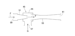
- FIG. FIG. 2 is a schematic configuration diagram showing an ejector used in the liquefied gas transfer piping system of FIG. 1.
- FIG. 1 is a schematic diagram showing an example of liquefied gas storage equipment to which a liquefied gas transfer piping system according to an embodiment of the present disclosure is applied.
- FIG. 2 is a schematic configuration diagram showing the liquefied gas transfer piping system according to the embodiment of FIG. 1.
- FIG. 2 is a perspective view showing a cover used in the
- FIG. 1 shows a liquefied gas transfer piping system (hereinafter simply referred to as "piping system 1") 1 according to an embodiment of the present disclosure.
- the piping system 1 is applied to, for example, liquefied gas storage equipment such as a liquefied gas storage ship S1 or a land-based liquefied gas storage base S2.
- the piping system 1 includes piping 3 for transferring liquefied gas.
- the piping system 1 is connected, for example, to a tank 11 of a liquefied gas storage ship S1.
- a ship such as the liquefied gas storage ship S1 will be mainly described as an example of the liquefied gas storage facility.
- liquefied gas storage ship S1 refers to a ship having a function of storing liquefied gas.
- the liquefied gas storage ship S1 in this embodiment is a liquefied gas carrier ship.
- the liquefied gas storage ship S1 includes, for example, a liquefied gas fuel ship, a bunkering ship that supplies liquefied gas to other ships, and the like.
- the liquefied gas storage equipment is not limited to a ship as long as it has a structure and function for storing liquefied gas, and may be, for example, a land-based liquefied gas storage equipment or a plant that utilizes liquefied gas.
- the piping 3 is configured as a vacuum insulated piping having a double structure. That is, the piping 3 includes an inner tube 5 through which liquefied gas passes, and an outer tube 7 that covers the inner tube 5. A vacuum layer 9 is formed in the radial gap between the inner tube 5 and the outer tube 7.
- the liquefied gas transferred by the pipe 3 is, for example, ammonia (LNH 3 , approximately -30°C), liquefied petroleum gas (LPG, approximately -45°C), liquefied carbon dioxide (LCO 2 , approximately -80°C), or liquefied ethylene.
- Gas (LEG, approx. -100°C), liquefied natural gas (LNG, approx. -160°C), liquefied nitrogen (LN 2 , approx. -200°C), liquefied hydrogen (LH 2 , approx. -250°C), liquefied helium (LHe) , approximately -270°C).
- liquefied hydrogen is transferred via piping 3.
- the piping system 1 includes a connection structure that connects a plurality of piping 3.
- the piping system 1 includes a first piping 3A and a second piping 3B that constitute a piping 3 and are connected in series.
- first inner pipe 5A first inner pipe 5A
- first outer pipe 7A second inner pipe 5B
- second outer tube 7B second outer tube 7B
- the first pipe 3A and the second pipe 3B are connected via a portion 5a of each inner pipe 5 that protrudes from the end of the outer pipe 7 (herein simply referred to as a "protrusion").
- each end of the first protruding portion 5Aa and the second protruding portion 5Ba is provided with a connecting portion 13 that is connected to each other, that is, a first connecting portion 13A and a second connecting portion 13B.
- each connecting portion 13A, 13B is formed as a flange joint.
- the connecting portion 13 is not limited to a flange joint, and may be a joint generally used for connecting the piping 3, such as a threaded joint, a bite joint, or a QCDC (Quick Connect/Disconnect Couplings).
- the piping system 1 includes a cover 15 that is attached to the first piping 3A and the second piping 3B and covers the first protrusion 5Aa and the second protrusion 5Ba in a sealed state.
- the cover 15 is provided from the end of the first outer tube 7A to the end of the second outer tube 7B, and the inner space 17 of the cover 15 is provided with the first protrusion 5Aa and the second protrusion 5Ba.
- the connecting portion of the piping 3 to be constructed is housed therein.
- the cover 15 is detachably attached to the first pipe 3A and the second pipe 3B.
- the cover 15 is formed into a cylindrical shape as a whole.
- the cover 15 has a substantially cylindrical shape.
- axial direction Attachment portions 19 are provided on the outer circumferential surfaces of 7B, respectively, to be attached by fitting in a sealed state.
- the cover 15 is composed of a plurality of divided cylinders 15A and 15B, which are two in this example.
- a substantially flat plate-shaped connecting portion 21 that protrudes in the radial direction and extends in the axial direction X is formed at the portion where the two divided cylindrical bodies 15A, 15B are connected.
- the two divided cylindrical bodies 15A and 15B are connected by fastening the connecting portions 21 to each other using a fastening member 23 such as a bolt, for example. Further, by tightening both the connecting portions 21 with the fastening member 23, the attachment portion 19 of the cover 15 is pressed against the outer circumferential surface of the outer tube 7, and the cover 15 is fixed to the piping 3.
- the cover 15 may be composed of three or more divided cylindrical bodies.
- the shape of the cover 15 is not limited to a cylindrical shape, and may be other shapes such as a rectangular tube shape.
- the cover 15 is provided with a sealing layer that seals between the inner space 17 and the outside of the cover 15.
- the cover 15 includes a first seal layer 25 formed inside the mounting portion 19 shown in FIG. and a second sealing layer 27 formed therebetween.
- a first seal member 31 such as a packing made of an elastic material is provided on the inner circumference, and on the outer circumference of the first seal member 31.
- a first inert gas sealing layer 33 filled with an inert gas is formed.
- the first sealing member 31 and the first inert gas sealing layer 33 form the first sealing layer 25 .
- a second seal member 35 is fitted into the radially inner region and outer region through the gap.
- a second inert gas seal layer 37 is formed between the second seal members 35 .
- the second sealing layer 27 is formed by the second sealing member 35 and the second inert gas sealing layer 37.
- nitrile rubber is used as the elastic material forming the first seal member 31 and the second seal member 35.
- the elastic material forming these seal members 31 and 35 is not limited to this, and may be a material commonly used for seals, such as silicone rubber, urethane rubber, ethylene/propylene rubber, or Teflon (registered trademark). It's good to be there. Further, different types of elastic materials may be used for the first seal member 31 and the second seal member 35.
- a recess 21a recessed outward from the inner wall surface is provided in the connecting portion 21 of one of the divided cylinders 15A and 15B, and a second inert gas seal layer 37 is formed at a position corresponding to the recess 21a. has been done.
- the second inert gas seal layer 37 of the second seal layer 27 and the first inert gas seal layer 33 of the first seal layer 25 in FIG. 1 are in communication with each other.
- nitrogen gas is used as the inert gas
- the first inert gas seal layer 33 is supplied with inert gas from a nitrogen supply source mounted on the liquefied gas storage vessel S1 (FIG. 2).
- Inert gas is supplied via line 39.
- the manner in which the inert gas is supplied is not particularly limited; for example, it may be supplied from an inert gas cylinder installed in the liquefied gas storage ship S1 (FIG. 2), or it may be supplied from a supply facility on land. .
- a heat insulating member 41 is attached to the inner peripheral surface of the cover 15.
- a vacuum insulation panel is used as the insulation member 41.
- the heat insulating member 41 may be a powder instead of a panel-shaped member.
- the material used as the heat insulating material of the heat insulating member 41 is not particularly limited, and may be, for example, an organic polymeric material such as polyurethane foam or polyethylene foam, or an inorganic material such as perlite.
- the heat insulating member 41 may be attached to the outer circumferential surface of the cover 15 instead of the inner circumferential surface.
- the cover 15 may have a double structure in which a vacuum heat insulating layer is formed inside.
- the temperature of the inner space 17 can be maintained at a low temperature. Thereby, heat input to the liquefied gas to be transported can be suppressed, and vaporization of the liquefied gas can be suppressed. However, it is not essential to provide the heat insulating member 41.
- the piping system 1 includes an exhaust device 43 that exhausts air from the inner space 17 of the cover 15.
- the ejector 45 is used as the exhaust device 43.
- an exhaust passage 47 connected to the inner space 17 of the cover 15 is provided, and an ejector 45 is provided in the middle of the exhaust passage 47.
- the exhaust passage 47 is connected to the inner space 17 via the side wall of the cover 15.
- the ejector 45 includes a nozzle section 51, a diffuser section 53 disposed downstream of the nozzle section 51 and concentrically with the nozzle section 51, and a main body that connects the nozzle section 51 and the diffuser section 53. 55.
- the main body portion 55 is provided with a suction port 57 that opens in a direction substantially perpendicular to the axes of the nozzle portion 51 and the diffuser portion 53.
- the driving fluid F is supplied from the fluid inlet 59 of the nozzle portion 51, and the gas G is sucked from the suction port 57 by the negative pressure generated by the driving fluid F flowing out from the tip of the nozzle portion 51 at high speed.
- the sucked gas G is discharged to the outside from the discharge port 61 of the diffuser section 53 together with the driving fluid F.
- the suction port 57 of the ejector 45 is connected to an ejector connecting pipe 63 connected to the cover 15 and forming an upstream portion of the exhaust passage 47.
- the ejector connecting pipe 63 is provided with a check valve 65 that prevents fluid from flowing from the ejector 45 side to the inner space 17 side.
- a discharge port 61 of the ejector 45 is connected to a discharge pipe 67 that forms a downstream portion of the exhaust passage 47 and discharges the above-mentioned driving fluid F and gas.
- the ejector 45 is driven by an inert gas, in this example nitrogen gas.
- the fluid supply pipe of the ejector 45 is connected to an inert gas branch supply path 71 connected to the first inert gas sealing layer 33 of the cover 15 .
- Inert gas from a nitrogen gas supply source is supplied to the ejector 45 via the first inert gas seal layer 33 and the inert gas branch supply path 71.
- the inert gas supply system can be simplified.
- the exhaust device 43 is not limited to the ejector 45, and may be, for example, various types of vacuum pumps.
- the ejector 45 as the exhaust device 43, there is no need for electrical equipment for driving it, so the degree of freedom in arrangement is increased in the liquefied gas storage facility, which will be described later and has many dangerous locations.
- a supply source of an inert gas such as nitrogen gas is usually installed in a liquefied gas storage facility, by using an inert gas as the driving fluid F of the ejector 45, an additional source for driving the ejector 45 can be added. No equipment is required.
- the type of inert gas is not limited to this, and may be, for example, carbon dioxide gas, helium gas, argon gas, etc.
- the same type of inert gas is used for the inert gas seal layers 33 and 37 and the ejector 45.
- This configuration has advantages such as sharing the inert gas supply source and simplifying the supply system, but it is also possible to use different types of inert gas for the inert gas seal layers 33 and 37 and the ejector 45. It's okay.
- the discharge pipe 67 connected to the ejector 45 is connected to a vent mast 73 provided in the liquefied gas storage ship S1.
- the inert gas discharged from the discharge port 61 of the ejector 45 is discharged into the atmosphere via the vent mast 73.
- the vent mast 73 is provided to discharge gas, for example, when the pressure of the stored gas increases in the liquefied gas storage tank 11 (FIG. 2).
- the vent mast 73 connected to the ejector 45 may be a vent mast provided not on the liquefied gas storage ship S1 but on the land facility S2 side. Furthermore, it is not essential to exhaust the inert gas through the vent mast 73.
- a gas detection device 75 for detecting liquefied gas is provided in the exhaust passage 47 connected to the ejector 45, which is the exhaust device 43, in this example, the exhaust pipe 67.
- the gas detection device 75 By providing the gas detection device 75 in the exhaust passage 47, leakage of liquefied gas from the inner pipe 5 can be detected at an early stage.
- the gas detection device 75 may be placed anywhere on the exhaust passage 47, not limited to the exhaust pipe 67.
- the gas detection device 75 is, for example, a gas concentration detection device that detects the concentration of a target gas.
- a gas concentration detection device stores, for example, a sensor element that detects a physical quantity to be detected, various circuits that perform necessary processing such as signal conversion processing and arithmetic processing on the obtained detected quantity, and information necessary for these processing.
- the device is equipped with a memory, a power supply circuit such as a power supply element such as a battery, a power supply circuit for receiving power supply from the outside, a transmission circuit for transmitting an output signal to the outside by wire or wirelessly, and the like.
- the gas detection device 75 is not limited to a gas concentration detection device.
- the gas detection device 75 may be a gas detection tape attached to a gas outlet provided in the exhaust passage 47.
- the liquefied gas transfer piping system 1 can be installed in a dangerous location in a liquefied gas storage facility.
- the term "hazardous area” here refers to a place where explosion-proof performance and types of equipment that can be installed are regulated by various standards due to the presence or risk of leakage of flammable or explosive substances.
- the liquefied gas transfer piping system 1 according to the present embodiment can be installed, for example, in a Type 1 hazardous area or a Type 2 hazardous area around the tank 11 (FIG. 2).
- the liquefied gas transfer piping system 1 is a device that exhausts air using the ejector 45 driven by an inert gas, and does not require electrical equipment, so it is not subject to regulations due to hazardous locations. . Therefore, even in a liquefied gas storage facility that is mostly located in a dangerous area, such as the liquefied gas storage ship S1, the piping system 1 can be freely installed in a location suitable for exhausting air.
- the piping system 1 can be provided with various valves and measuring instruments as necessary.
- a coupling meter 77 is provided on the cover 15.
- the piping system 1 is used for transferring liquefied hydrogen. Since liquefied hydrogen has a lower temperature than liquefied oxygen, there is a great advantage in applying the piping system 1 described above. However, the piping system 1 according to this embodiment can be used for transferring other than liquefied hydrogen.
- the piping system 1 includes a first piping 3A having a first inner pipe 5A and a first outer pipe 7A, which transports liquefied gas, and a first pipe 3A that transports liquefied gas.
- the second pipe 3B has a second inner pipe 5B and a second outer pipe 7B, and is connected to the first pipe 3A.
- the piping system 1 further includes a first connecting portion 13A disposed at the first protruding portion 5Aa of the first inner tube 5A, which is a portion protruding from the end of the first outer tube 7A, and a first connecting portion 13A of the second inner tube 5B.
- a second connecting portion 13B connected to the first connecting portion 13A which is disposed on the second protruding portion 5Ba that is a portion protruding from the end of the second outer tube 7B, and the first piping 3A and the second piping 3B.
- the cover 15 is attached to and covers the first protrusion 5Aa and the second protrusion 5Ba in a sealed state, and the exhaust device 43 exhausts air from the inner space 17 of the cover 15.
- the exhaust device 43 may be the ejector 45 in the piping system 1 according to the first aspect. According to this configuration, by using the ejector 45 as the exhaust device 43, there is no need for electrical equipment for driving, so the degree of freedom in arrangement is increased in a liquefied gas storage facility where there are many dangerous places.
- the ejector 45 may be the ejector 45 driven by an inert gas in the piping system 1 according to the first or second aspect.
- an inert gas supply source such as nitrogen gas that is normally installed in liquefied gas storage equipment can be used, so additional equipment for driving the ejector 45 is not required.
- the piping system 1 according to the fourth aspect of the present embodiment is the piping system 1 according to any one of the first to third aspects, in which the cover 15 has a space between the inner space 17 and the outside of the cover 15.
- a sealing inert gas seal may be provided. According to this configuration, outside air can be effectively prevented from entering the inner space 17 of the cover 15, and even if leakage into the inner space 17 occurs, inert gas cannot flow in. Therefore, the production of liquefied oxygen can be effectively suppressed.
- a source of inert gas such as nitrogen gas, which is normally installed in liquefied gas storage facilities, can be used.
- the piping system 1 according to the fifth aspect of the present embodiment is the piping system 1 according to the fourth aspect, in which the cover 15 has a plurality of divided cylinders 15A and 15B, and a connecting portion of these divided cylinders.
- the inert gas seal may be placed in between. According to this configuration, by configuring the cover 15 from the divided cylindrical bodies 15A and 15B, the cover 15 can be easily manufactured and removed, and the airtightness of the cover 15 can be ensured.
- the piping system 1 according to the sixth aspect of the present embodiment is the piping system 1 according to any one of the first to seventh aspects, in which the cover 15 is attached to the first piping 3A and the second piping 3B at the attachment part.
- An inert gas seal may be provided. According to this configuration, even when the cover 15 is configured to be removably attached to both the pipes 3A, 3B, the airtightness between the cover 15 and both the pipes 3A, 3B can be ensured.
- a piping system 1 according to a seventh aspect of the present embodiment supplies inert gas from the inert gas seal of the cover 15 to the ejector 45 in the piping system 1 according to any one of the first to seventh aspects.
- An inert gas branch supply path 71 may further be provided. According to this configuration, the inert gas supplied to the inert gas seal can be effectively utilized, and the inert gas supply system can be simplified.
- a gas for detecting liquefied gas is provided in the exhaust passage 47 connected to the exhaust device 43.
- a detection device 75 may be arranged. According to this configuration, leakage of liquefied gas from the inner tube 5 can be detected at an early stage.
- a piping system 1 according to a ninth aspect of the present embodiment is the piping system 1 according to any one of the first to eighth aspects, in which the cover 15 is detachably attached to the first piping 3A and the second piping 3B. It may be attached to. According to this configuration, it becomes easy to attach and detach the cover 15 as necessary.
- Parts may be located in hazardous locations. As described above, since the ejector 45 does not require electrical equipment for driving, it becomes possible to install the piping system 1 in a hazardous location.
Landscapes
- Engineering & Computer Science (AREA)
- General Engineering & Computer Science (AREA)
- Mechanical Engineering (AREA)
- Filling Or Discharging Of Gas Storage Vessels (AREA)
Abstract
A piping system (1) comprising first piping (3A) that has a first inner pipe (5A) and a first outer pipe (7A) which transfer liquefied gas, second piping (3B) that has a second inner pipe (5B) and a second outer pipe (7B) and that is connected to the first piping, a first connection part (13A) that is disposed at a first protruding part (5Aa), which is a part of the first inner pipe (5A) protruding from an end part of the first outer pipe (7A), and a second connection part (13B) that is disposed at a second protruding part (5Ba), which is a part of the second inner pipe (5B) protruding from an end part of the second outer pipe (7B), and that is connected to the first connection part (13A), said piping system (1) being provided with a cover (15) that is attached to the first piping (3A) and the second piping (3B) and that covers the first protruding part (5Aa) and the second protruding part (5Ba) in a sealed state, and an exhaust device (43) that discharges from a space (17) inside the cover (15).
Description
本開示は、液化ガスの移送に用いられる配管システムに関する。
The present disclosure relates to a piping system used for transporting liquefied gas.
従来、液化天然ガスや液化水素といった液化ガスを移送するための配管として、二重構造の真空断熱管を用いることが提案されている(例えば、特許文献1参照)。この二重管は、内管を、断熱層を介して外管が覆う構造を有しているので、高い断熱性が得られ、内管内を流れる低温の液化ガスの温度上昇を効果的に抑制することができる。
Conventionally, it has been proposed to use a double-walled vacuum insulated pipe as a pipe for transferring liquefied gas such as liquefied natural gas or liquefied hydrogen (see, for example, Patent Document 1). This double pipe has a structure in which the inner pipe is covered by the outer pipe through a heat insulating layer, which provides high insulation properties and effectively suppresses the temperature rise of the low-temperature liquefied gas flowing inside the inner pipe. can do.
液化ガスの移送用配管は、外管から突出させた内管同士を接続することになる。このような内管同士の接続部分の周辺では、内管を流れる液化ガスの低温によって液化酸素が生成される可能性があるので、これを防止する必要がある。
The liquefied gas transfer piping connects the inner tubes protruding from the outer tube. There is a possibility that liquefied oxygen will be generated in the vicinity of such a connecting portion between the inner tubes due to the low temperature of the liquefied gas flowing through the inner tubes, so it is necessary to prevent this.
本開示の目的は、上記の課題を解決するために、二重構造を有する液化ガス移送用配管の、外管から露出した内管同士の接続部分を簡易な構成とし、かつその周辺において液化酸素の生成を抑制することにある。
In order to solve the above-mentioned problems, an object of the present disclosure is to simplify the connection part between the inner pipes exposed from the outer pipe of a liquefied gas transfer pipe having a double structure, and to provide liquefied oxygen in the vicinity thereof. The goal is to suppress the generation of
上記目的を達成するために、本開示に係る液化ガス移送用配管システムは、
液化ガスを移送する、第1内管および第1外管を有する第1配管と、
第2内管および第2外管を有し、前記第1配管に接続される第2配管と、
前記第1内管の、前記第1外管の端部から突出した部分である第1突出部に配置された第1接続部と、
前記第2内管の、前記第2外管の端部から突出した部分である第2突出部に配置された、前記第1接続部に接続される第2接続部と、
前記第1配管および前記第2配管に取り付けられて、前記第1突出部および前記第2突出部を密閉状態で覆うカバーと、
前記カバーの内方空間から排気する排気装置と、
を備える。 In order to achieve the above object, the liquefied gas transfer piping system according to the present disclosure includes:
a first pipe that transports liquefied gas and has a first inner pipe and a first outer pipe;
a second pipe having a second inner pipe and a second outer pipe and connected to the first pipe;
a first connecting portion disposed at a first protruding portion of the first inner tube that is a portion protruding from an end of the first outer tube;
a second connecting portion connected to the first connecting portion, which is disposed at a second protruding portion of the second inner tube that is a portion protruding from an end of the second outer tube;
a cover that is attached to the first pipe and the second pipe and covers the first protrusion and the second protrusion in a sealed state;
an exhaust device that exhausts air from the inner space of the cover;
Equipped with.
請求の範囲および/または明細書および/または図面に開示された少なくとも2つの構成のどのような組合せも、本開示に含まれる。特に、請求の範囲の各請求項の2つ以上のどのような組合せも、本開示に含まれる。
Any combination of at least two features disclosed in the claims and/or the specification and/or drawings is included in the present disclosure. In particular, any combination of two or more of each of the following claims is included in the present disclosure.
本開示は、添付の図面を参考にした以下の好適な実施形態の説明から、より明瞭に理解されるであろう。しかしながら、実施形態および図面は単なる図示および説明のためのものであり、本開示の範囲を定めるために利用されるべきものではない。本開示の範囲は添付の請求の範囲によって定まる。添付図面において、複数の図面における同一の符号は、同一または相当する部分を示す。
本開示の一実施形態に係るの液化ガス移送用配管システムが適用される液化ガス貯留設備の一例を示す模式図である。
図1の実施形態に係る液化ガス移送用配管システムを示す概略構成図である。
図1の液化ガス移送用配管システムに使用されるカバーを示す斜視図である。
図1のIV-IV線に沿った断面図である。
図1の液化ガス移送用配管システムに使用されるエジェクタを示す概略構成図である。
The present disclosure will be more clearly understood from the following description of preferred embodiments with reference to the accompanying drawings. However, the embodiments and drawings are merely for illustration and explanation and should not be used to define the scope of the present disclosure. The scope of the disclosure is defined by the appended claims. In the accompanying drawings, the same reference numerals in multiple drawings indicate the same or corresponding parts.
FIG. 1 is a schematic diagram showing an example of liquefied gas storage equipment to which a liquefied gas transfer piping system according to an embodiment of the present disclosure is applied. FIG. 2 is a schematic configuration diagram showing the liquefied gas transfer piping system according to the embodiment of FIG. 1. FIG. FIG. 2 is a perspective view showing a cover used in the liquefied gas transfer piping system of FIG. 1. FIG. FIG. 2 is a sectional view taken along line IV-IV in FIG. 1. FIG. FIG. 2 is a schematic configuration diagram showing an ejector used in the liquefied gas transfer piping system of FIG. 1. FIG.
以下、本開示の好ましい実施形態について図面を参照しながら説明する。図1に、本開示の一実施形態に係る液化ガス移送用配管システム(以下、単に「配管システム1」という。)1を示す。配管システム1は、例えば液化ガス貯留船S1や陸上の液化ガス貯留基地S2といった液化ガス貯留設備に適用される。配管システム1は、液化ガスを移送するための配管3を備える。配管システム1は、例えば、液化ガス貯留船S1のタンク11に接続されている。
Hereinafter, preferred embodiments of the present disclosure will be described with reference to the drawings. FIG. 1 shows a liquefied gas transfer piping system (hereinafter simply referred to as "piping system 1") 1 according to an embodiment of the present disclosure. The piping system 1 is applied to, for example, liquefied gas storage equipment such as a liquefied gas storage ship S1 or a land-based liquefied gas storage base S2. The piping system 1 includes piping 3 for transferring liquefied gas. The piping system 1 is connected, for example, to a tank 11 of a liquefied gas storage ship S1.
本実施形態では、液化ガス貯留設備として、主に液化ガス貯留船S1のような船舶を例として説明する。本明細書において「液化ガス貯留船S1」とは、液化ガスを貯留する機能を有する船舶を指す。本実施形態における液化ガス貯留船S1は液化ガス運搬船である。液化ガス運搬船以外にも、例えば液化ガス燃料船や、液化ガスを他の船舶に供給するバンカリング船等が液化ガス貯留船S1に含まれる。もっとも、液化ガス貯留設備は、液化ガスを貯留する構造、機能を有する設備であれば船舶に限定されず、例えば地上の液化ガス貯留設備や、液化ガスを利用するプラントであってよい。
In this embodiment, a ship such as the liquefied gas storage ship S1 will be mainly described as an example of the liquefied gas storage facility. In this specification, "liquefied gas storage ship S1" refers to a ship having a function of storing liquefied gas. The liquefied gas storage ship S1 in this embodiment is a liquefied gas carrier ship. In addition to the liquefied gas carrier, the liquefied gas storage ship S1 includes, for example, a liquefied gas fuel ship, a bunkering ship that supplies liquefied gas to other ships, and the like. However, the liquefied gas storage equipment is not limited to a ship as long as it has a structure and function for storing liquefied gas, and may be, for example, a land-based liquefied gas storage equipment or a plant that utilizes liquefied gas.
図2に示すように、配管3は、二重構造を有する真空断熱配管として構成されている。すなわち、配管3は、液化ガスを通過させる内管5と、内管5を覆う外管7とから構成されている。内管5と外管7との間の径方向の隙間に真空層9が形成される。
As shown in FIG. 2, the piping 3 is configured as a vacuum insulated piping having a double structure. That is, the piping 3 includes an inner tube 5 through which liquefied gas passes, and an outer tube 7 that covers the inner tube 5. A vacuum layer 9 is formed in the radial gap between the inner tube 5 and the outer tube 7.
配管3によって移送される液化ガスは、例えば、アンモニア(LNH3、約-30℃)、液化石油ガス(LPG、約-45℃)、液化二酸化炭素(LCO2、約-80℃)、液化エチレンガス(LEG、約-100℃)、液化天然ガス(LNG、約-160℃)、液化窒素(LN2、約-200℃)、液化水素(LH2、約-250℃)、液化ヘリウム(LHe、約-270℃)である。本実施形態では、液化水素が配管3を介して移送される。
The liquefied gas transferred by the pipe 3 is, for example, ammonia (LNH 3 , approximately -30°C), liquefied petroleum gas (LPG, approximately -45°C), liquefied carbon dioxide (LCO 2 , approximately -80°C), or liquefied ethylene. Gas (LEG, approx. -100℃), liquefied natural gas (LNG, approx. -160℃), liquefied nitrogen (LN 2 , approx. -200℃), liquefied hydrogen (LH 2 , approx. -250℃), liquefied helium (LHe) , approximately -270°C). In this embodiment, liquefied hydrogen is transferred via piping 3.
図1に示すように、本実施形態に係る配管システム1は、複数の配管3を接続する接続構造を備える。配管システム1は、配管3を構成する、直列に接続された第1配管3Aおよび第2配管3Bを備える。以下の説明では、第1配管3A,第2配管3Bを構成する内管5および外管7を、「第1内管5A」,「第1外管7A」,「第2内管5B」,「第2外管7B」と呼ぶ場合がある。
As shown in FIG. 1, the piping system 1 according to the present embodiment includes a connection structure that connects a plurality of piping 3. The piping system 1 includes a first piping 3A and a second piping 3B that constitute a piping 3 and are connected in series. In the following description, the inner pipe 5 and outer pipe 7 that constitute the first pipe 3A and the second pipe 3B will be referred to as "first inner pipe 5A", "first outer pipe 7A", "second inner pipe 5B", It may also be referred to as the "second outer tube 7B."
第1配管3Aと第2配管3Bとは、それぞれの内管5の、外管7の端部から突出した部分(本明細書では単に「突出部」という。)5aを介して接続されている。具体的には、第1突出部5Aa,第2突出部5Baの各端部には、互いに接続される接続部13、つまり第1接続部13A,第2接続部13Bが設けられている。図示の例では、各接続部13A,13Bは、フランジ継手として形成されている。なお、接続部13はフランジ継手に限定されず、例えば、ねじ継手、食込み継手、QCDC(Quick Connect/Disconnect Couplings)等一般的に配管3の接続に用いられる継手であってよい。
The first pipe 3A and the second pipe 3B are connected via a portion 5a of each inner pipe 5 that protrudes from the end of the outer pipe 7 (herein simply referred to as a "protrusion"). . Specifically, each end of the first protruding portion 5Aa and the second protruding portion 5Ba is provided with a connecting portion 13 that is connected to each other, that is, a first connecting portion 13A and a second connecting portion 13B. In the illustrated example, each connecting portion 13A, 13B is formed as a flange joint. Note that the connecting portion 13 is not limited to a flange joint, and may be a joint generally used for connecting the piping 3, such as a threaded joint, a bite joint, or a QCDC (Quick Connect/Disconnect Couplings).
配管システム1は、第1配管3Aおよび第2配管3Bに取り付けられて、第1突出部5Aaおよび第2突出部5Baを密閉状態で覆うカバー15を備えている。換言すれば、カバー15は第1外管7Aの端部から第2外管7Bの端部に渡って設けられ、カバー15の内方空間17に第1突出部5Aaおよび第2突出部5Baで構成される配管3の接続部分が収容されている。カバー15は、第1配管3Aおよび第2配管3Bに着脱自在に取り付けられている。
The piping system 1 includes a cover 15 that is attached to the first piping 3A and the second piping 3B and covers the first protrusion 5Aa and the second protrusion 5Ba in a sealed state. In other words, the cover 15 is provided from the end of the first outer tube 7A to the end of the second outer tube 7B, and the inner space 17 of the cover 15 is provided with the first protrusion 5Aa and the second protrusion 5Ba. The connecting portion of the piping 3 to be constructed is housed therein. The cover 15 is detachably attached to the first pipe 3A and the second pipe 3B.
図3に示すように、カバー15は全体として筒状に形成されている。この例ではカバー15はほぼ円筒形状を有している。図1に示すように、カバー15の、配管3の軸心方向X(以下、単に「軸心方向X」という。)における両端部には、第1外管7Aの外周面および第2外管7Bの外周面にそれぞれシール状態で嵌合することにより取り付けられる取付部19が設けられている。
As shown in FIG. 3, the cover 15 is formed into a cylindrical shape as a whole. In this example, the cover 15 has a substantially cylindrical shape. As shown in FIG. 1, at both ends of the cover 15 in the axial direction X of the piping 3 (hereinafter simply referred to as "axial direction Attachment portions 19 are provided on the outer circumferential surfaces of 7B, respectively, to be attached by fitting in a sealed state.
また、図4に示すように、カバー15は、複数、この例では2つの分割筒体15A,15Bから構成されている。両分割筒体15A,15Bが連結される部分には、径方向に突出し軸心方向Xに延びる、ほぼ平板状の連結部21が形成されている。連結部21が互いに、例えばボルトのような締結部材23によって締結されることにより、2つの分割筒体15A,15Bが連結される。また、両連結部21が締結部材23によって締め付けられることにより、カバー15の取付部19が外管7の外周面に押し付けられ、カバー15が配管3に固定される。なお、カバー15は、3つ以上の分割筒体から構成されていてもよい。また、カバー15の形状は、円筒形状に限定されず、角筒形状等、他の形状であってよい。
Further, as shown in FIG. 4, the cover 15 is composed of a plurality of divided cylinders 15A and 15B, which are two in this example. A substantially flat plate-shaped connecting portion 21 that protrudes in the radial direction and extends in the axial direction X is formed at the portion where the two divided cylindrical bodies 15A, 15B are connected. The two divided cylindrical bodies 15A and 15B are connected by fastening the connecting portions 21 to each other using a fastening member 23 such as a bolt, for example. Further, by tightening both the connecting portions 21 with the fastening member 23, the attachment portion 19 of the cover 15 is pressed against the outer circumferential surface of the outer tube 7, and the cover 15 is fixed to the piping 3. Note that the cover 15 may be composed of three or more divided cylindrical bodies. Further, the shape of the cover 15 is not limited to a cylindrical shape, and may be other shapes such as a rectangular tube shape.
カバー15には、内方空間17と当該カバー15の外部との間をシールするシール層が設けられている。具体的には、この例では、カバー15は、図1に示す取付部19の内部に形成された第1シール層25と、図4に示す2つの分割筒体15A,15Bの連結部21の間に形成された第2シール層27とを有する。
The cover 15 is provided with a sealing layer that seals between the inner space 17 and the outside of the cover 15. Specifically, in this example, the cover 15 includes a first seal layer 25 formed inside the mounting portion 19 shown in FIG. and a second sealing layer 27 formed therebetween.
図1に示すように、取付部19の内部において、内周部には、弾性材料から形成されたパッキンのような第1シール部材31が設けられており、第1シール部材31の外周側に、不活性ガスが充填された第1不活性ガスシール層33が形成されている。これら第1シール部材31と第1不活性ガスシール層33により、第1シール層25が形成されている。取付部19に第1不活性ガスシール層を形成することにより、カバー15を両配管3A,3Bに着脱可能に構成した場合にも、カバー15と両配管3A,3Bとの間の密閉性を確保することができる。
As shown in FIG. 1, inside the mounting portion 19, a first seal member 31 such as a packing made of an elastic material is provided on the inner circumference, and on the outer circumference of the first seal member 31. , a first inert gas sealing layer 33 filled with an inert gas is formed. The first sealing member 31 and the first inert gas sealing layer 33 form the first sealing layer 25 . By forming the first inert gas seal layer on the mounting portion 19, even when the cover 15 is configured to be removably attached to both the pipes 3A and 3B, the airtightness between the cover 15 and both the pipes 3A and 3B can be maintained. can be secured.
図4に示すように、2つの分割筒体15A,15Bの連結部21間の隙間において、径方向の内側領域と外側領域に、隙間を介して第2シール部材35が嵌め込まれており、これら第2シール部材35の間に第2不活性ガスシール層37が形成されている。これら第2シール部材35と第2不活性ガスシール層37により、第2シール層27が形成されている。分割筒体15A,15Bの連結部21間に第2不活性ガスシール層37を形成することにより、カバー15を分割筒体15A,15Bから構成することでカバー15の作製および着脱が容易になり、かつ、カバー15の密閉性を確保することができる。
As shown in FIG. 4, in the gap between the connecting portions 21 of the two divided cylinders 15A and 15B, a second seal member 35 is fitted into the radially inner region and outer region through the gap. A second inert gas seal layer 37 is formed between the second seal members 35 . The second sealing layer 27 is formed by the second sealing member 35 and the second inert gas sealing layer 37. By forming the second inert gas seal layer 37 between the connecting portions 21 of the split cylinders 15A and 15B, the cover 15 is made up of the split cylinders 15A and 15B, and the cover 15 can be easily manufactured and removed. Moreover, the airtightness of the cover 15 can be ensured.
第1シール部材31および第2シール部材35を形成する弾性材料として、本実施形態ではニトリルゴム(NBR)を用いている。もっとも、これらのシール部材31,35を形成する弾性材料はこれに限定されず、例えばシリコーンゴム、ウレタンゴム、エチレン・プロピレンゴム、テフロン(登録商標)等の一般的にシール用に用いられる材料であってよい。また、第1シール部材31と第2シール部材35とに異なる種類の弾性材料が使用されていてもよい。
In this embodiment, nitrile rubber (NBR) is used as the elastic material forming the first seal member 31 and the second seal member 35. However, the elastic material forming these seal members 31 and 35 is not limited to this, and may be a material commonly used for seals, such as silicone rubber, urethane rubber, ethylene/propylene rubber, or Teflon (registered trademark). It's good to be there. Further, different types of elastic materials may be used for the first seal member 31 and the second seal member 35.
図示の例では、一方の分割筒体15A,15Bの連結部21に、内壁面から外側に凹む凹部21aが設けられており、凹部21aに相当する位置に第2不活性ガスシール層37が形成されている。第2シール層27の第2不活性ガスシール層37と、図1の第1シール層25の第1不活性ガスシール層33とは互いに連通している。本実施形態では、不活性ガスとして窒素ガスを使用しており、第1不活性ガスシール層33には、液化ガス貯留船S1(図2)に搭載された窒素供給源から、不活性ガス供給路39を介して不活性ガスが供給される。なお、不活性ガスの供給態様は、特に限定されず、例えば液化ガス貯留船S1(図2)に設置した不活性ガスのボンベから供給してもく、陸上の供給設備から供給してもよい。
In the illustrated example, a recess 21a recessed outward from the inner wall surface is provided in the connecting portion 21 of one of the divided cylinders 15A and 15B, and a second inert gas seal layer 37 is formed at a position corresponding to the recess 21a. has been done. The second inert gas seal layer 37 of the second seal layer 27 and the first inert gas seal layer 33 of the first seal layer 25 in FIG. 1 are in communication with each other. In this embodiment, nitrogen gas is used as the inert gas, and the first inert gas seal layer 33 is supplied with inert gas from a nitrogen supply source mounted on the liquefied gas storage vessel S1 (FIG. 2). Inert gas is supplied via line 39. Note that the manner in which the inert gas is supplied is not particularly limited; for example, it may be supplied from an inert gas cylinder installed in the liquefied gas storage ship S1 (FIG. 2), or it may be supplied from a supply facility on land. .
本実施形態において、カバー15の内周面には、断熱部材41が取り付けられている。この例では、断熱部材41として、真空断熱パネルが使用されている。断熱部材41は、パネル状の部材ではなく、粉体であってもよい。断熱部材41の断熱材として用いられる素材は、特に限定されないが、例えばポリウレタンフォームやポリエチレンフォームといった有機高分子系材料や、パーライトのような無機材料であってよい。また、断熱部材41は、カバー15の内周面ではなく、外周面に取り付けられていてもよい。また、カバー15は、内部に真空断熱層が形成される二重構造を有していてもよい。
In this embodiment, a heat insulating member 41 is attached to the inner peripheral surface of the cover 15. In this example, a vacuum insulation panel is used as the insulation member 41. The heat insulating member 41 may be a powder instead of a panel-shaped member. The material used as the heat insulating material of the heat insulating member 41 is not particularly limited, and may be, for example, an organic polymeric material such as polyurethane foam or polyethylene foam, or an inorganic material such as perlite. Further, the heat insulating member 41 may be attached to the outer circumferential surface of the cover 15 instead of the inner circumferential surface. Further, the cover 15 may have a double structure in which a vacuum heat insulating layer is formed inside.
カバー15に断熱部材41を設けることにより、内方空間17の温度を低温に維持することができる。これにより、輸送対象の液化ガスへの入熱を抑え、液化ガスの気化を抑制することができる。もっとも、断熱部材41を設けることは必須ではない。
By providing the heat insulating member 41 on the cover 15, the temperature of the inner space 17 can be maintained at a low temperature. Thereby, heat input to the liquefied gas to be transported can be suppressed, and vaporization of the liquefied gas can be suppressed. However, it is not essential to provide the heat insulating member 41.
配管システム1は、カバー15の内方空間17から排気する排気装置43を備えている。本実施形態では、エジェクタ45を排気装置43として使用している。具体的には、カバー15の内方空間17に接続された排気通路47が設けられており、排気通路47の途中にエジェクタ45が設けられている。排気通路47はカバー15の側壁を介して内方空間17に接続されている。
The piping system 1 includes an exhaust device 43 that exhausts air from the inner space 17 of the cover 15. In this embodiment, the ejector 45 is used as the exhaust device 43. Specifically, an exhaust passage 47 connected to the inner space 17 of the cover 15 is provided, and an ejector 45 is provided in the middle of the exhaust passage 47. The exhaust passage 47 is connected to the inner space 17 via the side wall of the cover 15.
図5に示すように、エジェクタ45は、ノズル部51と、ノズル部51の下流側に、ノズル部51と同心に配置されたディフューザ部53と、ノズル部51とディフューザ部53とを接続する本体部55とを備えている。本体部55には、ノズル部51およびディフューザ部53の軸心にほぼ直交する方向に開口する吸込口57が設けられている。ノズル部51の流体入口59から駆動流体Fが供給され、ノズル部51の先端から高速で流出する駆動流体Fによって生じる負圧によって、吸込口57から気体Gが吸い込まれる。吸い込まれた気体Gは、駆動流体Fと共にディフューザ部53の吐出口61から外部へ吐出される。
As shown in FIG. 5, the ejector 45 includes a nozzle section 51, a diffuser section 53 disposed downstream of the nozzle section 51 and concentrically with the nozzle section 51, and a main body that connects the nozzle section 51 and the diffuser section 53. 55. The main body portion 55 is provided with a suction port 57 that opens in a direction substantially perpendicular to the axes of the nozzle portion 51 and the diffuser portion 53. The driving fluid F is supplied from the fluid inlet 59 of the nozzle portion 51, and the gas G is sucked from the suction port 57 by the negative pressure generated by the driving fluid F flowing out from the tip of the nozzle portion 51 at high speed. The sucked gas G is discharged to the outside from the discharge port 61 of the diffuser section 53 together with the driving fluid F.
この例では、図1に示すように、排気通路47の上流部を形成する、カバー15に連結されたエジェクタ接続管63にエジェクタ45の吸込口57が接続されている。エジェクタ接続管63には、エジェクタ45側から内方空間17側への流体の流れを防止する逆流防止弁65が設けられている。エジェクタ45の吐出口61には、排気通路47の下流部を形成する、上述の駆動流体Fと気体とを排出する排出管67が接続されている。
In this example, as shown in FIG. 1, the suction port 57 of the ejector 45 is connected to an ejector connecting pipe 63 connected to the cover 15 and forming an upstream portion of the exhaust passage 47. The ejector connecting pipe 63 is provided with a check valve 65 that prevents fluid from flowing from the ejector 45 side to the inner space 17 side. A discharge port 61 of the ejector 45 is connected to a discharge pipe 67 that forms a downstream portion of the exhaust passage 47 and discharges the above-mentioned driving fluid F and gas.
図1に示す例では、エジェクタ45として、不活性ガス、この例では窒素ガスによって駆動されるエジェクタ45を使用している。この例では、エジェクタ45の流体供給管は、カバー15の第1不活性ガスシール層33に接続された不活性ガス分岐供給路71に接続されている。窒素ガス供給源からの不活性ガスが、第1不活性ガスシール層33および不活性ガス分岐供給路71を介してエジェクタ45に供給される。このように、配管システム1が不活性ガス分岐供給路71を備えていることにより、不活性ガスシール、この例では第1不活性ガスシール層33に供給される不活性ガスを有効活用できるとともに、不活性ガスの供給系統を簡素化することができる。
In the example shown in FIG. 1, the ejector 45 is driven by an inert gas, in this example nitrogen gas. In this example, the fluid supply pipe of the ejector 45 is connected to an inert gas branch supply path 71 connected to the first inert gas sealing layer 33 of the cover 15 . Inert gas from a nitrogen gas supply source is supplied to the ejector 45 via the first inert gas seal layer 33 and the inert gas branch supply path 71. In this way, by providing the piping system 1 with the inert gas branch supply path 71, it is possible to effectively utilize the inert gas supplied to the inert gas seal, in this example, the first inert gas seal layer 33. , the inert gas supply system can be simplified.
なお、排気装置43はエジェクタ45に限定されず、例えば、各種の真空ポンプ等であってもよい。もっとも、排気装置43としてエジェクタ45を用いることにより、駆動のための電気設備が不要となるので、後述する危険場所が多く存在する液化ガス貯留設備において配置の自由度が大きくなる。また、窒素ガスのような不活性ガスの供給源は、液化ガス貯留設備に通常設置されているので、エジェクタ45の駆動流体Fを不活性ガスとすることにより、エジェクタ45を駆動するための追加設備が不要となる。
Note that the exhaust device 43 is not limited to the ejector 45, and may be, for example, various types of vacuum pumps. However, by using the ejector 45 as the exhaust device 43, there is no need for electrical equipment for driving it, so the degree of freedom in arrangement is increased in the liquefied gas storage facility, which will be described later and has many dangerous locations. Further, since a supply source of an inert gas such as nitrogen gas is usually installed in a liquefied gas storage facility, by using an inert gas as the driving fluid F of the ejector 45, an additional source for driving the ejector 45 can be added. No equipment is required.
なお、本実施形態では、不活性ガスとして窒素ガスを使用する例について説明したが、不活性ガスの種類はこれに限定されず、例えば二酸化炭素ガス、ヘリウムガス、アルゴンガス等であってよい。また、本実施形態では、不活性ガスシール層33,37とエジェクタ45に同じ種類の不活性ガスを使用する例について説明した。このように構成することにより、不活性ガスの供給源の共通化や供給系統の簡素化といった利点があるが、不活性ガスシール層33,37とエジェクタ45に異なる種類の不活性ガスを使用してもよい。
Note that in this embodiment, an example in which nitrogen gas is used as the inert gas has been described, but the type of inert gas is not limited to this, and may be, for example, carbon dioxide gas, helium gas, argon gas, etc. Further, in this embodiment, an example has been described in which the same type of inert gas is used for the inert gas seal layers 33 and 37 and the ejector 45. This configuration has advantages such as sharing the inert gas supply source and simplifying the supply system, but it is also possible to use different types of inert gas for the inert gas seal layers 33 and 37 and the ejector 45. It's okay.
本実施形態では、エジェクタ45に接続された排出管67は、液化ガス貯留船S1に設けられたベントマスト73に接続されている。エジェクタ45の吐出口61から排出された不活性ガスは、ベントマスト73を介して大気中に放出される。ベントマスト73は、例えば液化ガスの貯留タンク11(図2)内において貯留ガスの圧力が高くなった場合に、ガスを放出するために設けられている。エジェクタ45から排出される不活性ガスをベントマスト73を介して放出することにより、エジェクタ45を利用してベントマスト73の不活性化を行うことができる。なお、エジェクタ45に接続されるベントマスト73は、液化ガス貯留船S1ではなく、陸上設備S2側に設けられたベントマストであってもよい。また、ベントマスト73を介して不活性ガスを排出することは必須ではない。
In this embodiment, the discharge pipe 67 connected to the ejector 45 is connected to a vent mast 73 provided in the liquefied gas storage ship S1. The inert gas discharged from the discharge port 61 of the ejector 45 is discharged into the atmosphere via the vent mast 73. The vent mast 73 is provided to discharge gas, for example, when the pressure of the stored gas increases in the liquefied gas storage tank 11 (FIG. 2). By discharging the inert gas discharged from the ejector 45 through the vent mast 73, the vent mast 73 can be inactivated using the ejector 45. Note that the vent mast 73 connected to the ejector 45 may be a vent mast provided not on the liquefied gas storage ship S1 but on the land facility S2 side. Furthermore, it is not essential to exhaust the inert gas through the vent mast 73.
排気装置43であるエジェクタ45に接続された排気通路47、この例では排出管67に、液化ガスを検知するガス検知機器75が設けられている。排気通路47にガス検知機器75を設けることにより、内管5からの液化ガスの漏洩を早期に検出することができる。なお、ガス検知機器75は、排気通路47上であれば、排出管67に限らず、どこに配置してもよい。
A gas detection device 75 for detecting liquefied gas is provided in the exhaust passage 47 connected to the ejector 45, which is the exhaust device 43, in this example, the exhaust pipe 67. By providing the gas detection device 75 in the exhaust passage 47, leakage of liquefied gas from the inner pipe 5 can be detected at an early stage. Note that the gas detection device 75 may be placed anywhere on the exhaust passage 47, not limited to the exhaust pipe 67.
ガス検知機器75は、具体的には、例えば対象ガスの濃度を検出するガス濃度検知装置である。ガス濃度検知装置は、例えば、検知対象の物理量を検知するセンサ素子、取得した検知量に対して信号変換処理、演算処理等必要な処理を行う各種回路、これらの処理に必要な情報を格納するためのメモリ、電池等の電源素子または外部から電源供給を受けるための電源回路、出力信号を有線または無線で外部へ送信するための送信回路等を備えている。もっとも、ガス検知機器75は、ガス濃度検知装置に限定されない。例えば、ガス検知機器75は、排気通路47に設けられたガス排出口に取り付けられたガス検知テープであってよい。
Specifically, the gas detection device 75 is, for example, a gas concentration detection device that detects the concentration of a target gas. A gas concentration detection device stores, for example, a sensor element that detects a physical quantity to be detected, various circuits that perform necessary processing such as signal conversion processing and arithmetic processing on the obtained detected quantity, and information necessary for these processing. The device is equipped with a memory, a power supply circuit such as a power supply element such as a battery, a power supply circuit for receiving power supply from the outside, a transmission circuit for transmitting an output signal to the outside by wire or wirelessly, and the like. However, the gas detection device 75 is not limited to a gas concentration detection device. For example, the gas detection device 75 may be a gas detection tape attached to a gas outlet provided in the exhaust passage 47.
液化ガス移送用配管システム1は、液化ガス貯留設備における危険場所に設置することができる。ここでの「危険場所」とは、引火性ないし爆発性を有する物質が存在、漏洩等するおそれがあることから各種規格によって防爆性能や設置可能な装置の種類につき規制を受ける場所をいう。具体的には、本実施形態に係る液化ガス移送用配管システム1は、例えばタンク11(図2)周辺の1種危険場所や2種危険場所にも設置することができる。
The liquefied gas transfer piping system 1 can be installed in a dangerous location in a liquefied gas storage facility. The term "hazardous area" here refers to a place where explosion-proof performance and types of equipment that can be installed are regulated by various standards due to the presence or risk of leakage of flammable or explosive substances. Specifically, the liquefied gas transfer piping system 1 according to the present embodiment can be installed, for example, in a Type 1 hazardous area or a Type 2 hazardous area around the tank 11 (FIG. 2).
すなわち、本実施形態に係る液化ガス移送用配管システム1は、不活性ガスによって駆動されるエジェクタ45を利用して排気する装置であり、電気設備を必要としないので、危険場所による規制を受けない。したがって、液化ガス貯留船S1のような、大部分が危険場所に該当する液化ガス貯留設備においても、配管システム1を、排気を行うために適した場所に自由に設置することができる。
That is, the liquefied gas transfer piping system 1 according to the present embodiment is a device that exhausts air using the ejector 45 driven by an inert gas, and does not require electrical equipment, so it is not subject to regulations due to hazardous locations. . Therefore, even in a liquefied gas storage facility that is mostly located in a dangerous area, such as the liquefied gas storage ship S1, the piping system 1 can be freely installed in a location suitable for exhausting air.
配管システム1には、上記で説明したもの以外にも、必要に応じて各種の弁や測定機器を設けることができる。例えば、図1の例では、カバー15に連成計77が設けられている。
In addition to those described above, the piping system 1 can be provided with various valves and measuring instruments as necessary. For example, in the example shown in FIG. 1, a coupling meter 77 is provided on the cover 15.
本実施形態では、上述したように、配管システム1を液化水素の移送用に用いている。液化水素は液化酸素よりも温度が低いので、上述した配管システム1を適用する利点が大きい。もっとも、本実施形態に係る配管システム1は、液化水素以外の移送用に用いることができる。
In this embodiment, as described above, the piping system 1 is used for transferring liquefied hydrogen. Since liquefied hydrogen has a lower temperature than liquefied oxygen, there is a great advantage in applying the piping system 1 described above. However, the piping system 1 according to this embodiment can be used for transferring other than liquefied hydrogen.
以上説明した本実施形態の第1の態様に係る配管システム1は、液化ガスを移送する、液化ガスを移送する、第1内管5Aおよび第1外管7Aを有する第1配管3Aと、第2内管5Bおよび第2外管7Bを有し、第1配管3Aに接続される第2配管3Bとを備える。配管システム1は、さらに、第1内管5Aの、第1外管7Aの端部から突出した部分である第1突出部5Aaに配置された第1接続部13Aと、第2内管5Bの、第2外管7Bの端部から突出した部分である第2突出部5Baに配置された、第1接続部13Aに接続される第2接続部13Bと、第1配管3Aおよび第2配管3Bに取り付けられて、第1突出部5Aaおよび第2突出部5Baを密閉状態で覆うカバー15と、カバー15の内方空間17から排気する排気装置43とを備える。この構成によれば、外管7から突出した内管の部分同士の接続部分を覆うカバー15および排気装置43を設けたことにより、外管から露出した部分の周囲を負圧に保つことができる。したがって、外管から露出した部分の周囲に存在する酸素の量を減らすことができるので、内管5同士の接続部分を簡易な構成としながら、液化酸素の生成を抑制することができる。
The piping system 1 according to the first aspect of the present embodiment described above includes a first piping 3A having a first inner pipe 5A and a first outer pipe 7A, which transports liquefied gas, and a first pipe 3A that transports liquefied gas. The second pipe 3B has a second inner pipe 5B and a second outer pipe 7B, and is connected to the first pipe 3A. The piping system 1 further includes a first connecting portion 13A disposed at the first protruding portion 5Aa of the first inner tube 5A, which is a portion protruding from the end of the first outer tube 7A, and a first connecting portion 13A of the second inner tube 5B. , a second connecting portion 13B connected to the first connecting portion 13A, which is disposed on the second protruding portion 5Ba that is a portion protruding from the end of the second outer tube 7B, and the first piping 3A and the second piping 3B. The cover 15 is attached to and covers the first protrusion 5Aa and the second protrusion 5Ba in a sealed state, and the exhaust device 43 exhausts air from the inner space 17 of the cover 15. According to this configuration, by providing the cover 15 and the exhaust device 43 that cover the connection portion between the parts of the inner tube that protrude from the outer tube 7, it is possible to maintain negative pressure around the portion exposed from the outer tube. . Therefore, it is possible to reduce the amount of oxygen existing around the portion exposed from the outer tube, so it is possible to suppress the generation of liquefied oxygen while making the connecting portion between the inner tubes 5 simple.
本実施形態の第2の態様に係る配管システム1は、第1の態様に係る配管システム1において、前記排気装置43がエジェクタ45であってよい。この構成によれば、排気装置43としてエジェクタ45を用いることにより、駆動のための電気設備が不要となるので、危険場所が多く存在する液化ガス貯留設備において配置の自由度が大きくなる。
In the piping system 1 according to the second aspect of the present embodiment, the exhaust device 43 may be the ejector 45 in the piping system 1 according to the first aspect. According to this configuration, by using the ejector 45 as the exhaust device 43, there is no need for electrical equipment for driving, so the degree of freedom in arrangement is increased in a liquefied gas storage facility where there are many dangerous places.
本実施形態の第3の態様に係る配管システム1は、第1または第2の態様に係る配管システム1において、エジェクタ45が、不活性ガスによって駆動されるエジェクタ45であってよい。この構成によれば、液化ガス貯留設備に通常設置されている窒素ガスのような不活性ガスの供給源を利用できるので、エジェクタ45を駆動するための追加設備が不要となる。
In the piping system 1 according to the third aspect of the present embodiment, the ejector 45 may be the ejector 45 driven by an inert gas in the piping system 1 according to the first or second aspect. According to this configuration, an inert gas supply source such as nitrogen gas that is normally installed in liquefied gas storage equipment can be used, so additional equipment for driving the ejector 45 is not required.
本実施形態の第4の態様に係る配管システム1は、第1から第3のいずれかの態様に係る配管システム1において、カバー15に、内方空間17と当該カバー15の外部との間をシールする不活性ガスシールが配置されていてもよい。この構成によれば、外気がカバー15の内方空間17に侵入することを効果的に防止ることができるとともに、内方空間17への漏洩が発生したとしても、不活性ガスが流入するに留まるので、液化酸素の生成を効果的に抑制することができる。また、液化ガス貯留設備に通常設置されている窒素ガスのような不活性ガスの供給源を利用することができる。
The piping system 1 according to the fourth aspect of the present embodiment is the piping system 1 according to any one of the first to third aspects, in which the cover 15 has a space between the inner space 17 and the outside of the cover 15. A sealing inert gas seal may be provided. According to this configuration, outside air can be effectively prevented from entering the inner space 17 of the cover 15, and even if leakage into the inner space 17 occurs, inert gas cannot flow in. Therefore, the production of liquefied oxygen can be effectively suppressed. Additionally, a source of inert gas such as nitrogen gas, which is normally installed in liquefied gas storage facilities, can be used.
本実施形態の第5の態様に係る配管システム1は、第4の態様に係る配管システム1において、カバー15が複数の分割筒体15A,15Bを有しており、これら分割筒体の連結部間に前記不活性ガスシールが配置されていてもよい。この構成によれば、カバー15を分割筒体15A,15Bから構成することによりカバー15の作製および着脱が容易になり、かつ、カバー15の密閉性を確保することができる。
The piping system 1 according to the fifth aspect of the present embodiment is the piping system 1 according to the fourth aspect, in which the cover 15 has a plurality of divided cylinders 15A and 15B, and a connecting portion of these divided cylinders. The inert gas seal may be placed in between. According to this configuration, by configuring the cover 15 from the divided cylindrical bodies 15A and 15B, the cover 15 can be easily manufactured and removed, and the airtightness of the cover 15 can be ensured.
本実施形態の第6の態様に係る配管システム1は、第1から第7のいずれかの態様に係る配管システム1において、カバー15の第1配管3Aおよび第2配管3Bへの取付部に前記不活性ガスシールが配置されているいてもよい。この構成によれば、カバー15を両配管3A,3Bに着脱可能に構成した場合にも、カバー15と両配管3A,3Bとの間の密閉性を確保することができる。
The piping system 1 according to the sixth aspect of the present embodiment is the piping system 1 according to any one of the first to seventh aspects, in which the cover 15 is attached to the first piping 3A and the second piping 3B at the attachment part. An inert gas seal may be provided. According to this configuration, even when the cover 15 is configured to be removably attached to both the pipes 3A, 3B, the airtightness between the cover 15 and both the pipes 3A, 3B can be ensured.
本実施形態の第7の態様に係る配管システム1は、第1から第7のいずれかの態様に係る配管システム1において、カバー15の前記不活性ガスシールからエジェクタ45へ不活性ガスを供給する不活性ガス分岐供給路71をさらに備えていてもよい。この構成によれば、前記不活性ガスシールに供給される不活性ガスを有効活用できるとともに、不活性ガスの供給系統を簡素化することができる。
A piping system 1 according to a seventh aspect of the present embodiment supplies inert gas from the inert gas seal of the cover 15 to the ejector 45 in the piping system 1 according to any one of the first to seventh aspects. An inert gas branch supply path 71 may further be provided. According to this configuration, the inert gas supplied to the inert gas seal can be effectively utilized, and the inert gas supply system can be simplified.
本実施形態の第8の態様に係る配管システム1は、第1から第7のいずれかの態様に係る配管システム1において、排気装置43に接続された排気通路47に、液化ガスを検知するガス検知機器75が配置されていてもよい。この構成によれば、内管5からの液化ガスの漏洩を早期に検出することができる。
In the piping system 1 according to the eighth aspect of the present embodiment, in the piping system 1 according to any one of the first to seventh aspects, a gas for detecting liquefied gas is provided in the exhaust passage 47 connected to the exhaust device 43. A detection device 75 may be arranged. According to this configuration, leakage of liquefied gas from the inner tube 5 can be detected at an early stage.
本実施形態の第9の態様に係る配管システム1は、第1から第8のいずれかの態様に係る配管システム1において、前記カバー15が前記第1配管3Aおよび前記第2配管3Bに着脱自在に取り付けられていてもよい。この構成によれば、必要に応じてカバー15を着脱することが容易になる。
A piping system 1 according to a ninth aspect of the present embodiment is the piping system 1 according to any one of the first to eighth aspects, in which the cover 15 is detachably attached to the first piping 3A and the second piping 3B. It may be attached to. According to this configuration, it becomes easy to attach and detach the cover 15 as necessary.
本実施形態の第10の態様に係る配管システム1は、第1から第9のいずれかの態様に係る配管システム1において、排気装置43としてエジェクタ45を使用する場合、少なくともカバー15で覆われた部分が危険場所に設置されていてもよい。上述したように、エジェクタ45では駆動のための電気設備が不要となるので、配管システム1を危険場所に設置することが可能になる。
In the piping system 1 according to the tenth aspect of the present embodiment, when the ejector 45 is used as the exhaust device 43 in the piping system 1 according to any one of the first to ninth aspects, Parts may be located in hazardous locations. As described above, since the ejector 45 does not require electrical equipment for driving, it becomes possible to install the piping system 1 in a hazardous location.
以上のとおり、図面を参照しながら本開示の好適な実施形態を説明したが、本開示の趣旨を逸脱しない範囲内で、種々の追加、変更または削除が可能である。したがって、そのようなものも本開示の範囲内に含まれる。
As described above, the preferred embodiments of the present disclosure have been described with reference to the drawings, but various additions, changes, or deletions can be made without departing from the spirit of the present disclosure. Accordingly, such are also included within the scope of this disclosure.
1 液化ガス移送用配管システム
3 配管
3A 第1配管
3B 第2配管
5 内管
5A 第1内管
5B 第2内管
5Aa 第1突出部
5Ba 第2突出部
7 外管
7A 第1外管
7B 第2外管
13A 第1接続部
13B 第2接続部
15 カバー
15A,15B 分割筒体
17 内方空間
19 取付部
33 第1不活性ガスシール
37 第2不活性ガスシール
43 排気装置
45 エジェクタ
47 排気通路
51 不活性ガス供給源
71 不活性ガス分岐供給路
75 ガス検知機器 1 Piping system for liquefiedgas transfer 3 Piping 3A First piping 3B Second piping 5 Inner tube 5A First inner tube 5B Second inner tube 5Aa First protrusion 5Ba Second protrusion 7 Outer tube 7A First outer tube 7B 2 outer tube 13A first connection part 13B second connection part 15 cover 15A, 15B divided cylinder 17 inner space 19 mounting part 33 first inert gas seal 37 second inert gas seal 43 exhaust device 45 ejector 47 exhaust passage 51 Inert gas supply source 71 Inert gas branch supply path 75 Gas detection equipment
3 配管
3A 第1配管
3B 第2配管
5 内管
5A 第1内管
5B 第2内管
5Aa 第1突出部
5Ba 第2突出部
7 外管
7A 第1外管
7B 第2外管
13A 第1接続部
13B 第2接続部
15 カバー
15A,15B 分割筒体
17 内方空間
19 取付部
33 第1不活性ガスシール
37 第2不活性ガスシール
43 排気装置
45 エジェクタ
47 排気通路
51 不活性ガス供給源
71 不活性ガス分岐供給路
75 ガス検知機器 1 Piping system for liquefied
Claims (10)
- 液化ガスを移送する、第1内管および第1外管を有する第1配管と、
第2内管および第2外管を有し、前記第1配管に接続される第2配管と、
前記第1内管の、前記第1外管の端部から突出した部分である第1突出部に配置された第1接続部と、
前記第2内管の、前記第2外管の端部から突出した部分である第2突出部に配置された、前記第1接続部に接続される第2接続部と、
前記第1配管および前記第2配管に取り付けられて、前記第1突出部および前記第2突出部を密閉状態で覆うカバーと、
前記カバーの内方空間から排気する排気装置と、
を備える液化ガス移送用配管システム。 a first pipe that transports liquefied gas and has a first inner pipe and a first outer pipe;
a second pipe having a second inner pipe and a second outer pipe and connected to the first pipe;
a first connecting portion disposed at a first protruding portion of the first inner tube that is a portion protruding from an end of the first outer tube;
a second connecting portion connected to the first connecting portion, which is disposed at a second protruding portion of the second inner tube that is a portion protruding from an end of the second outer tube;
a cover that is attached to the first pipe and the second pipe and covers the first protrusion and the second protrusion in a sealed state;
an exhaust device that exhausts air from the inner space of the cover;
A piping system for transporting liquefied gas. - 請求項1に記載の液化ガス移送用配管システムにおいて、
前記排気装置がエジェクタである、
液化ガス移送用配管システム。 The liquefied gas transfer piping system according to claim 1,
the exhaust device is an ejector;
Piping system for liquefied gas transfer. - 請求項2に記載の液化ガス配管システムにおいて、
前記エジェクタが、不活性ガスによって駆動されるエジェクタである、
液化ガス移送用配管システム。 The liquefied gas piping system according to claim 2,
the ejector is an ejector driven by an inert gas,
Piping system for liquefied gas transfer. - 請求項1から3のいずれか一項に記載の液化ガス移送用配管システムにおいて、
前記カバーに、前記内方空間と当該カバーの外部との間をシールする不活性ガスシールが配置されている、
液化ガス移送用配管システム。 The liquefied gas transfer piping system according to any one of claims 1 to 3,
An inert gas seal is disposed on the cover to seal between the inner space and the outside of the cover.
Piping system for liquefied gas transfer. - 請求項4に記載の液化ガス移送用配管システムにおいて、
前記カバーが複数の分割筒体を有しており、これら分割筒体の連結部間に前記不活性ガスシールが配置されている、
液化ガス移送用配管システム。 The liquefied gas transfer piping system according to claim 4,
The cover has a plurality of divided cylindrical bodies, and the inert gas seal is arranged between connecting parts of these divided cylindrical bodies.
Piping system for liquefied gas transfer. - 請求項4または5に記載の液化ガス移送用配管システムにおいて、
前記カバーの前記第1配管および前記第2配管への取付部に前記不活性ガスシールが配置されている、
液化ガス移送用配管システム。 The liquefied gas transfer piping system according to claim 4 or 5,
the inert gas seal is disposed at an attachment portion of the cover to the first piping and the second piping;
Piping system for liquefied gas transfer. - 請求項4に記載の液化ガス移送用配管システムにおいて、
前記カバーの前記不活性ガスシールから前記エジェクタへ不活性ガスを供給する不活性ガス分岐供給路をさらに備える、
液化ガス移送用配管システム。 The liquefied gas transfer piping system according to claim 4,
further comprising an inert gas branch supply path for supplying inert gas from the inert gas seal of the cover to the ejector;
Piping system for liquefied gas transfer. - 請求項1から3のいずれか一項に記載の液化ガス移送用配管システムにおいて、
前記排気装置に接続された排気通路に、前記液化ガスを検知するガス検知機器が配置されている、
液化ガス移送用配管システム。 The liquefied gas transfer piping system according to any one of claims 1 to 3,
A gas detection device for detecting the liquefied gas is arranged in an exhaust passage connected to the exhaust device,
Piping system for liquefied gas transfer. - 請求項1から3のいずれか一項に記載の液化ガス移送用配管システムにおいて、
前記カバーが前記第1配管および前記第2配管に着脱自在に取り付けられている、
液化ガス移送用配管システム。 The liquefied gas transfer piping system according to any one of claims 1 to 3,
the cover is removably attached to the first pipe and the second pipe;
Piping system for liquefied gas transfer. - 請求項2または3に記載の液化ガス移送用配管システムにおいて、
少なくとも前記カバーで覆われた部分が危険場所に設置されている、
液化ガス移送用配管システム。 The liquefied gas transfer piping system according to claim 2 or 3,
At least the portion covered by the cover is installed in a hazardous location;
Piping system for liquefied gas transfer.
Priority Applications (1)
| Application Number | Priority Date | Filing Date | Title |
|---|---|---|---|
| PCT/JP2022/021982 WO2023233479A1 (en) | 2022-05-30 | 2022-05-30 | Liquefied gas transfer piping system |
Applications Claiming Priority (1)
| Application Number | Priority Date | Filing Date | Title |
|---|---|---|---|
| PCT/JP2022/021982 WO2023233479A1 (en) | 2022-05-30 | 2022-05-30 | Liquefied gas transfer piping system |
Publications (1)
| Publication Number | Publication Date |
|---|---|
| WO2023233479A1 true WO2023233479A1 (en) | 2023-12-07 |
Family
ID=89025935
Family Applications (1)
| Application Number | Title | Priority Date | Filing Date |
|---|---|---|---|
| PCT/JP2022/021982 WO2023233479A1 (en) | 2022-05-30 | 2022-05-30 | Liquefied gas transfer piping system |
Country Status (1)
| Country | Link |
|---|---|
| WO (1) | WO2023233479A1 (en) |
Citations (3)
| Publication number | Priority date | Publication date | Assignee | Title |
|---|---|---|---|---|
| JPS6359297U (en) * | 1986-10-06 | 1988-04-20 | ||
| JP2017202783A (en) * | 2016-05-13 | 2017-11-16 | 川崎重工業株式会社 | Connection structure between vessel and loading arm |
| JP2022042602A (en) * | 2020-09-03 | 2022-03-15 | 株式会社荏原製作所 | Hydrogen dilution apparatus and hydrogen dilution method |
-
2022
- 2022-05-30 WO PCT/JP2022/021982 patent/WO2023233479A1/en unknown
Patent Citations (3)
| Publication number | Priority date | Publication date | Assignee | Title |
|---|---|---|---|---|
| JPS6359297U (en) * | 1986-10-06 | 1988-04-20 | ||
| JP2017202783A (en) * | 2016-05-13 | 2017-11-16 | 川崎重工業株式会社 | Connection structure between vessel and loading arm |
| JP2022042602A (en) * | 2020-09-03 | 2022-03-15 | 株式会社荏原製作所 | Hydrogen dilution apparatus and hydrogen dilution method |
Similar Documents
| Publication | Publication Date | Title |
|---|---|---|
| US7740287B2 (en) | Flexible joint for cryogenic pipe | |
| US5927762A (en) | Pipe coupling assembly system and method | |
| US9360144B2 (en) | Conduit with joint covered by a boot | |
| US3885595A (en) | Conduit for cryogenic fluid transportation | |
| KR102111473B1 (en) | A vacuum insulated pipe | |
| CN109416150A (en) | Gas dome for sealing insulated tank constructs | |
| CN111094833B (en) | Sealed and thermally insulated container comprising a gas-collecting dome | |
| WO2023233479A1 (en) | Liquefied gas transfer piping system | |
| US10544883B2 (en) | Conduit seal assembly | |
| US11788666B2 (en) | Johnston coupling with additional vacuum enclosure | |
| CN108930858A (en) | Connecting flange for double-walled high-pressure air pipe | |
| US11598467B2 (en) | Johnston coupling with galvanic separation | |
| US7104727B1 (en) | Piping system with transition coupling | |
| CN214618252U (en) | Conveying pipeline | |
| WO2022259936A1 (en) | Vacuum evacuation device | |
| CN115370971A (en) | Coupling for vacuum insulated pipes | |
| CN201141489Y (en) | Butt joint structure of vacuum tube | |
| CN113883405A (en) | Hydrogen tank and hydrogen pipe covered with two-dimensional material, and device for transporting hydrogen | |
| US20230135912A1 (en) | Optimized connection assembly between two portions of a cryogenic line, comprising a double sealing barrier, a fluid expansion chamber and a detector for detecting the presence of the fluid in said chamber | |
| WO2024079830A1 (en) | Piping unit for cryogenic fluid transfer | |
| KR102499089B1 (en) | Insulation structure of flange joint for cryogenic gas | |
| JP2011127638A (en) | Joint structure of fluid transport pipe | |
| CN204986181U (en) | Double -walled expansion joint | |
| EP4163529A1 (en) | A process fluid conveying component | |
| CN209991211U (en) | Liquid unloading device for liquefied gas transport vehicle |
Legal Events
| Date | Code | Title | Description |
|---|---|---|---|
| 121 | Ep: the epo has been informed by wipo that ep was designated in this application |
Ref document number: 22944768 Country of ref document: EP Kind code of ref document: A1 |