WO2023228990A1 - Stator and rotatary electrical machine - Google Patents
Stator and rotatary electrical machine Download PDFInfo
- Publication number
- WO2023228990A1 WO2023228990A1 PCT/JP2023/019419 JP2023019419W WO2023228990A1 WO 2023228990 A1 WO2023228990 A1 WO 2023228990A1 JP 2023019419 W JP2023019419 W JP 2023019419W WO 2023228990 A1 WO2023228990 A1 WO 2023228990A1
- Authority
- WO
- WIPO (PCT)
- Prior art keywords
- bus bar
- coil
- bar holder
- stator
- holder
- Prior art date
Links
- 229920005989 resin Polymers 0.000 claims abstract description 74
- 239000011347 resin Substances 0.000 claims abstract description 74
- 239000000463 material Substances 0.000 claims description 8
- 238000000465 moulding Methods 0.000 claims description 7
- 238000000926 separation method Methods 0.000 claims description 2
- 230000017525 heat dissipation Effects 0.000 description 6
- 230000002093 peripheral effect Effects 0.000 description 4
- 239000003822 epoxy resin Substances 0.000 description 3
- 229920000647 polyepoxide Polymers 0.000 description 3
- 238000012986 modification Methods 0.000 description 2
- 230000004048 modification Effects 0.000 description 2
- 230000007935 neutral effect Effects 0.000 description 2
- 230000005855 radiation Effects 0.000 description 2
- 229920003002 synthetic resin Polymers 0.000 description 2
- 239000000057 synthetic resin Substances 0.000 description 2
- 229920006337 unsaturated polyester resin Polymers 0.000 description 2
- 229910000831 Steel Inorganic materials 0.000 description 1
- 239000000853 adhesive Substances 0.000 description 1
- 230000001070 adhesive effect Effects 0.000 description 1
- PNEYBMLMFCGWSK-UHFFFAOYSA-N aluminium oxide Inorganic materials [O-2].[O-2].[O-2].[Al+3].[Al+3] PNEYBMLMFCGWSK-UHFFFAOYSA-N 0.000 description 1
- 239000004020 conductor Substances 0.000 description 1
- 230000006866 deterioration Effects 0.000 description 1
- 238000010586 diagram Methods 0.000 description 1
- 230000000694 effects Effects 0.000 description 1
- 230000020169 heat generation Effects 0.000 description 1
- 239000012212 insulator Substances 0.000 description 1
- 230000003993 interaction Effects 0.000 description 1
- 230000002452 interceptive effect Effects 0.000 description 1
- 239000007769 metal material Substances 0.000 description 1
- 239000000843 powder Substances 0.000 description 1
- 125000006850 spacer group Chemical group 0.000 description 1
- 239000010959 steel Substances 0.000 description 1
- 238000003466 welding Methods 0.000 description 1
- 238000004804 winding Methods 0.000 description 1
Images


Classifications
-
- H—ELECTRICITY
- H02—GENERATION; CONVERSION OR DISTRIBUTION OF ELECTRIC POWER
- H02K—DYNAMO-ELECTRIC MACHINES
- H02K3/00—Details of windings
- H02K3/46—Fastening of windings on the stator or rotor structure
- H02K3/50—Fastening of winding heads, equalising connectors, or connections thereto
Definitions
- the present disclosure relates to a stator and a rotating electric machine.
- the stator described in Patent Document 1 includes a stator core having teeth, a coil wound around the teeth, and a bus bar electrically connected to the coil.
- the stator also includes a molded resin that collectively covers the coil and bus bar.
- the stator includes a stator core having teeth, a coil wound around the teeth, a bus bar electrically connected to the coil, a bus bar holder holding the bus bar, and a bus bar holder that holds the bus bar.
- the conductivity is lower than the thermal conductivity of the resin molded part.
- the rotating electrical machine includes a stator and a rotor facing the stator, and the stator includes a stator core having teeth and wound around the teeth.
- the bus bar holder includes a coil, a bus bar electrically connected to the coil, a bus bar holder that holds the bus bar, and a resin molded part that collectively covers the coil, the bus bar holder, and the bus bar.
- the bus bar holder has an intervening part disposed between the bus bar and the bus bar, and the bus bar holder including the intervening part has a thermal conductivity lower than that of the resin molded part.
- stator and rotating electric machine it is possible to suppress the heat of the bus bar from being transmitted to the coil surrounding area of the resin molded part by the intervening part of the bus bar holder having a lower thermal conductivity. This makes it possible to suppress the temperature rise in the resin molded portion around the coil. Therefore, it is possible to suppress a decrease in heat transfer performance from the coil to the resin molded portion due to a decrease in the temperature difference between the coil and the resin molded portion.
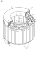
- FIG. 1 is a schematic diagram of a rotating electric machine in an embodiment
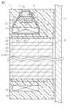
- FIG. 2 is a perspective view partially showing a stator of the same form in cross section
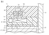
- FIG. 3 is a schematic cross-sectional view of a stator of the same type
- FIG. 4 is a schematic cross-sectional view of a stator of a modified example
- FIG. 5 is a schematic cross-sectional view of a stator according to a modified example.
- the rotating electric machine 10 includes a stator 11 and a rotor 12 facing the stator 11.
- the stator 11 has an annular shape.
- Rotor 12 is arranged inside stator 11 .
- the rotor 12 has a rotating shaft 13.
- the rotor 12 faces the stator 11, for example, in the radial direction.
- the stator 11 is housed in a cylindrical housing 14.
- the stator 11 is housed in the housing 14 by shrink fitting, for example.
- stator 11 (Configuration of stator 11) As shown in FIGS. 1 and 2, the stator 11 includes a stator core 20, a bobbin 30, a coil 40, a resin mold section 50, and a bus bar holder 60. In addition, in FIG. 2, a part of the resin mold part 50 is shown in cross section.
- the stator core 20 has a plurality of split cores 21 arranged in an annular manner along the circumferential direction of the stator 11.
- the stator core 20 of this embodiment has, for example, twelve divided cores 21.
- Each divided core 21 is made of, for example, a magnetic metal material.
- the circumferential direction of the stator 11, the radial direction of the stator 11, and the axial direction of the stator 11 may be simply referred to as the "circumferential direction,” "radial direction,” and "axial direction,” respectively.
- Each split core 21 has a core back 22 and teeth 23 extending from the core back 22 in the radial direction.
- the plurality of split cores 21 are arranged along the circumferential direction so that each core back 22 has an annular shape as a whole.
- Each tooth 23 extends along the radial direction.
- the teeth 23 protrude radially inward from the inner surface of the core back 22, for example.
- the tips of the teeth 23 face the axis L1 of the stator 11.
- the base end portion of the tooth 23 is the radially outer end portion of the tooth 23 .
- each split core 21 is formed of a plurality of core sheets 24 stacked in the axial direction.
- Each core sheet 24 is made of, for example, an electromagnetic steel plate.
- the core sheets 24 are fixed to each other by, for example, adhesive, caulking, laser welding, or the like.
- each core back 22 of each split core 21 are arranged in a ring shape in the circumferential direction.
- Each core back 22 is in contact with adjacent core backs 22 on both sides in the circumferential direction.
- the radially outer surface of each core back 22 contacts the inner circumferential surface of the housing 14 .
- the axial end faces of each core back 22 are located, for example, on the same plane perpendicular to the axis L1.
- Each split core 21 is provided with a bobbin 30.
- a plurality of bobbins 30 are provided corresponding to the plurality of divided cores 21, respectively.
- the bobbin 30 has a tooth covering portion 31 that covers the teeth 23.
- the coil 40 is wound around each tooth covering portion 31 by, for example, concentrated winding. That is, the teeth covering portion 31 of the bobbin 30 is interposed between the split core 21 and the coil 40. Thereby, the bobbin 30 electrically insulates between the split core 21 and the coil 40.
- each of the split core 21, bobbin 30, and coil 40 constitutes one integral part.
- the bobbin 30 is made of an insulator such as synthetic resin. As the material for the bobbin 30, for example, epoxy resin or the like can be used.
- the bobbin 30 is, for example, molded onto the split core 21. That is, it is formed integrally with the split core 21. This allows the bobbin 30 to be in close contact with the split core 21.
- a groove portion 32 extending in the radial direction is formed in a portion that covers the axial end surface of the tooth 23.
- the groove portion 32 is formed, for example, at the center of the tooth covering portion 31 in the circumferential direction. Further, the groove portion 32 is formed, for example, from one end of the bobbin 30 in the radial direction to the other end.
- the coil 40 is wired in three phases: U phase, V phase, and W phase.
- U phase When power is supplied to the coil 40, a rotating magnetic field for rotationally driving the rotor 12 is generated in the stator 11.
- the coils 40 are connected, for example, in a star connection having a neutral point.
- a bus bar 71 buried inside the bus bar holder 60 is electrically connected to the coil 40 so as to function, for example, as a neutral point terminal.
- the bus bar 71 has an annular or arcuate shape along the circumferential direction.
- the stator 11 has a connecting portion 72 that electrically connects the coils 40 to each other.
- the connecting portion 72 is, for example, a crossover wire that is a conducting wire continuous from the coil 40, or a bus bar made of a conductor separate from the conducting wire that constitutes the coil 40. Note that in the drawings, a region where a plurality of connecting portions 72 are arranged is illustrated as a connecting portion 72.
- the coil 40 has a first coil end 41 that is one end of the coil 40 in the axial direction, and a second coil end 42 that is the other end of the coil 40 in the axial direction. ing.
- the bus bar holder 60 holds a bus bar 71.
- the bus bar 71 is embedded inside the bus bar holder 60 by insert molding.
- the bus bar holder 60 is made of synthetic resin, for example.
- As a material for the bus bar holder 60 for example, epoxy resin, unsaturated polyester resin, or the like can be used.
- the bus bar holder 60 has a first covering part 61 , a second covering part 62 , and a third covering part 63 that cover the bus bar 71 .
- the first covering portion 61 is interposed between the coil 40 and the bus bar 71 in the axial direction.
- the first covering portion 61 covers the side surface of the bus bar 71 that faces the coil 40 in the axial direction.
- the first covering portion 61 is configured as an intervening portion disposed between the coil 40 and the bus bar 71.
- the second covering portion 62 covers the opposite side of the bus bar 71 from the first covering portion 61 in the axial direction.
- the third covering portion 63 covers both sides of the bus bar 71 in the radial direction. That is, in the cross section along the radial direction, the entire periphery of the bus bar 71 is covered by the first covering part 61, the second covering part 62, and the third covering part 63.
- the bus bar holder 60 and the bus bar 71 are provided on the sides of the coil 40 in the axial direction.
- the bus bar holder 60 and the bus bar 71 are provided near the first coil end 41 in the axial direction of the stator 11.
- the first covering portion 61 of the bus bar holder 60 is arranged between the coil 40 and the bus bar 71 in the axial direction. Further, the first covering portion 61 is spaced apart from the first coil end 41 in the axial direction.
- the bus bar holder 60 has a spacing section 64 that maintains the separation between the first coil end 41 and the first covering section 61.
- the spacing section 64 extends from, for example, the first covering section 61 and the third covering section 63.
- a plurality of interval holding parts 64 are provided, for example, at equal intervals in the circumferential direction.
- the tip of each spacer 64 is in contact with, for example, the bobbin 30 in the axial direction. Thereby, the distance between the first covering portion 61 of the bus bar holder 60 and the first coil end 41 is maintained.
- the connecting portion 72 is arranged on the opposite side of the bus bar holder 60 from the first coil end 41 in the axial direction. That is, the bus bar holder 60 is located between the connecting portion 72 and the first coil end 41 in the axial direction.
- the stator 11 includes a fixing band 73 that ties the connecting portion 72 and the bus bar holder 60 to the first coil end 41.
- a plurality of fixing bands 73 are provided.
- the number of fixing bands 73 is, for example, the same as the number of coils 40.
- the fixing band 73 is provided so as to collectively surround the connecting portion 72, the bus bar holder 60, and the first coil end 41 in a cross section along the radial direction.
- the bus bar holder 60 and the connecting portion 72 are fixed to the coil 40 in a state where the distance between the bus bar holder 60 and the first coil end 41 is maintained by each of the distance holding portions 64 .
- each fixing band 73 is passed through the groove portion 32 of the corresponding bobbin 30 to the inner peripheral side of the coil 40.
- the resin mold part 50 collectively covers, for example, a plurality of coils 40, a bus bar holder 60 including a bus bar 71, and a connecting part 72.
- the resin mold section 50 has a first mold section 51 that covers the first coil end 41 and a second mold section 52 that covers the second coil end 42 .
- the first mold part 51 collectively covers the first coil end 41 , the bus bar holder 60 including the bus bar 71 , the connecting part 72 , and each fixing band 73 .
- the first molded portion 51 covers both sides of the first coil end 41 in the radial direction. Further, the first mold part 51 covers both sides of the bus bar holder 60 in the radial direction. Further, the first molded portion 51 covers the axially outer side and the radially both sides of the connecting portion 72 .
- the second molded portion 52 covers the axially outer side and both radial sides of the second coil end 42 .
- the first mold part 51 has an intermediate part 53 that is inserted between the first coil end 41 and the first covering part 61 of the bus bar holder 60.
- the intermediate portion 53 is in close contact with the first coil end 41 and the first covering portion 61, respectively.
- the first mold part 51 has a filling part 54 that enters into the groove part 32.
- the filling portion 54 is interposed between the first coil end 41 and the tooth covering portion 31 of the bobbin 30.
- the filling portion 54 is in close contact with the surface of the groove portion 32 and the inner peripheral surface of the first coil end 41, respectively.
- each of the first mold part 51 and the second mold part 52 are spaced apart from the inner peripheral surface of the housing 14, for example. This makes it possible to prevent the housing 14 from interfering with the first molded part 51 and the second molded part 52 when the stator core 20 on which the resin molded part 50 is formed is housed in the housing 14 .
- the resin mold section 50 includes a third mold section 55 that connects the first mold section 51 and the second mold section 52 by passing between teeth 23 adjacent to each other in the circumferential direction. ing.
- the third mold part 55 is filled between each of the plurality of teeth 23.
- the first mold part 51 and the second mold part 52 are connected to each other by a plurality of third mold parts 55.
- an integral part including the split core 21, the bobbin 30, and the coil 40 is arranged in an annular shape.
- the bus bar holder 60 including the bus bar 71 is arranged to face the first coil end 41.
- each coil 40 is electrically connected to the bus bar 71.
- the bus bar holder 60 and the connecting portion 72 are fixed to the first coil end 41 using the fixing band 73 .
- a resin mold section 50 is molded to collectively cover each coil 40, each bobbin 30, bus bar holder 60, and connection section 72.
- the material of the resin mold part 50 for example, a material obtained by mixing epoxy resin or unsaturated polyester resin with alumina powder or the like can be used.
- the thermal conductivity of the resin mold part 50 is set to, for example, 2.0 (W/m ⁇ K) or more.
- the thermal conductivity of the bus bar holder 60 including the first covering portion 61 is set to be smaller than the thermal conductivity of the resin molded portion 50. In this embodiment, the thermal conductivity of the bus bar holder 60 is set to less than 2.0 (W/m ⁇ K).
- the thermal conductivity of the bobbin 30 is set to be smaller than that of the resin molded part 50.
- the thermal conductivity of the bobbin 30 is set to, for example, 1.0 (W/m ⁇ K) or less.
- the operation of this embodiment will be explained.
- the rotor 12 rotates due to interaction with a rotating magnetic field generated in the stator 11 by energizing each coil 40 .
- the coil 40 generates heat due to the energization.
- a part of the heat of the coil 40 is released to the outside via the resin molded part 50.
- An example of the heat radiation path is, for example, a heat radiation path from the coil 40 to the stator core 20 via the resin molded part 50.
- the resin mold part 50 is formed of a material having higher thermal conductivity than the bobbin 30, it is possible to further improve heat dissipation.
- bus bar 71 generates heat by energizing each coil 40.
- the main portion of the bus bar 71 is buried inside the bus bar holder 60.
- the bus bar holder 60 is set to have a lower thermal conductivity than the resin molded part 50. Heat transfer from the bus bar 71 to the resin molded part 50 is slowed down by the bus bar holder 60.
- the thermal conductivity of the bus bar holder 60 is lower than that of the resin molded part 50. According to this configuration, it is possible to suppress the heat of the bus bar 71 from being transmitted to the coil surrounding area of the resin molded part 50 by the bus bar holder 60 having a lower thermal conductivity. This makes it possible to suppress the temperature rise in the resin molded portion 50 around the coil. Therefore, it is possible to suppress a decrease in heat transfer performance from the coil 40 to the resin molded part 50 due to a decrease in the temperature difference between the coil 40 and the resin molded part 50.
- the bus bar 71 is embedded inside the bus bar holder 60 by insert molding. According to this configuration, the bus bar holder 60 covering the bus bar 71 can more appropriately slow down the heat transfer from the bus bar 71 to the resin molded part 50.
- the bus bar holder 60 and the bus bar 71 are provided on the sides of the coil 40 in the axial direction. This configuration is advantageous in reducing the size of the stator 11 in the radial direction.
- the bus bar holder 60 has a first covering section 61, a second covering section 62, and a third covering section 63.
- the first covering portion 61 covers the side surface of the bus bar 71 that faces the coil 40 in the axial direction.
- the first covering portion 61 is configured as an intervening portion disposed between the coil 40 and the bus bar 71.
- the second covering portion 62 covers the opposite side of the bus bar 71 from the first covering portion 61 in the axial direction.
- the third covering portion 63 covers both sides of the bus bar 71 in the radial direction. According to this configuration, the bus bar holder 60 including the first covering part 61, the second covering part 62, and the third covering part 63 can more preferably slow down the heat transfer from the bus bar 71 to the resin mold part 50. Become.
- the first covering portion 61 of the bus bar holder 60 and the coil 40 are arranged apart from each other.
- the resin molded part 50 has an intermediate part 53 inserted between the coil 40 and the first covering part 61. According to this configuration, it is possible to radiate the heat of the coil 40 to the intermediate portion 53 of the resin molded portion 50.
- the intermediate portion 53 is a part of the resin molded portion 50 and has a higher thermal conductivity than the bus bar holder 60. Therefore, the heat of the coil 40 can be efficiently radiated by the resin molded part 50 including the intermediate part 53.
- the bus bar holder 60 has a spacing section 64 that maintains the spaced state between the coil 40 and the first covering section 61. According to this configuration, the distance between the coil 40 and the first covering portion 61 is maintained by the distance holding portion 64, so that the intermediate portion 53 can be suitably formed.
- the stator 11 includes a connecting portion 72 that electrically connects the plurality of coils 40 to each other.
- the resin mold part 50 collectively covers the coil 40, the bus bar holder 60, and the connecting part 72.
- the bus bar holder 60 including the first covering portion 61 is located between the connecting portion 72 and the coil 40. According to this configuration, the bus bar holder 60 can suppress the heat of the connecting portion 72 from being transmitted to the portion around the coil of the resin molded portion 50.
- the stator 11 includes a fixing band 73 that restrains the bus bar holder 60 and the connecting portion 72 with respect to the coil 40. According to this configuration, before the resin mold part 50 is molded, the bus bar holder 60 and the connecting part 72 can be temporarily fixed to the coil 40 by the fixing band 73. Therefore, it is possible to prevent the bus bar holder 60 and the connecting portion 72 from shifting in position due to the filling pressure during molding of the resin mold portion 50.
- the resin mold part 50 has a first part 81 that covers the coil 40 and a second part 82 that covers the bus bar holder 60.
- the first portion 81 and the second portion 82 are made of materials having different thermal conductivities.
- the first portion 81 covers the first coil end 41.
- the second portion 82 collectively covers the bus bar holder 60 and the connecting portion 72.
- the second portion 82 overlaps the first portion 81 in the axial direction.
- the boundary between the first portion 81 and the second portion 82 is set between the first coil end 41 and the bus bar holder 60. That is, the intermediate portion 53 interposed between the first coil end 41 and the bus bar holder 60 is formed by a portion of the first portion 81 and a portion of the second portion 82 .
- the first portion 81 includes a filling portion 54 that enters into the groove portion 32 .
- the thermal conductivity of the second portion 82 is higher than that of the bus bar holder 60 and lower than the thermal conductivity of the first portion 81.
- the bus bar holder 60 and the second portion 82 can prevent the heat of the bus bar 71 from being transmitted to the first portion 81 covering the coil 40 .
- This makes it possible to suppress the temperature rise in the first portion 81 of the resin molded portion 50. Therefore, it is possible to suppress a decrease in heat transfer performance from the coil 40 to the first portion 81 due to a decrease in the temperature difference between the coil 40 and the first portion 81.
- the thermal conductivity of the second portion 82 is higher than that of the bus bar holder 60, it is possible to ensure heat dissipation from the second portion 82. As a result, it becomes possible to suppress deterioration of the heat dissipation performance of the resin molded part 50.
- the second portion 82 of the resin molded portion 50 collectively covers the bus bar holder 60 and the connecting portion 72. According to this configuration, the second portion 82 can suppress the heat of the connecting portion 72 from being transmitted to the first portion 81 that covers the coil 40 .
- a fixing band 73 may be provided to restrain the bus bar holder 60 and the connecting portion 72 with respect to the coil 40.
- the bus bar holder 60 including the bus bar 71 may be arranged so as to be lined up in the radial direction with respect to the first coil end 41. Such a configuration can contribute to miniaturization of the stator 11 in the axial direction.
- the bus bar holder 60 is arranged radially outward of the first coil end 41.
- the bus bar holder 60 includes an intervening portion 91 that is interposed between the first coil end 41 and the bus bar 71 in the radial direction.
- the resin molded portion 50 that covers the coil 40 and the bus bar holder 60 has an intermediate portion 92 inserted between the first coil end 41 and the intervening portion 91 .
- bus bar holder 60 is arranged on the radially outer side of the first coil end 41, but the bus bar holder 60 may be arranged on the radial inner side of the first coil end 41. .
- a connecting portion 72 that electrically connects the coils 40 may be provided within the resin mold portion 50.
- the connecting portion 72 by arranging the connecting portion 72 on the radially outer side of the bus bar holder 60, the bus bar holder 60 is placed between the connecting portion 72 and the coil 40. This makes it possible for the bus bar holder 60 to suppress the heat of the connecting portion 72 from being transmitted to the portions around the coil of the resin molded portion 50 .
- the tip of the spacing holding part 64 is in contact with the bobbin 30, but in addition to this, for example, the tip of the spacing holding part 64 may be in contact with, for example, the core back 22 of the stator core 20. good.
- the interval holding part 64 may be omitted from the bus bar holder 60.
- a column portion extending in the axial direction is formed on the bobbin 30.
- a configuration may be adopted in which the tip of the column portion of the bobbin 30 is brought into contact with the bus bar holder 60. Even with such a configuration, it becomes possible to maintain the separated state between the coil 40 and the bus bar holder 60 by the pillar portion, and as a result, it becomes possible to form the intermediate portion 53 suitably.
- the bus bar holder 60 and the connecting portion 72 are restrained to the coil 40 by the fixing band 73, but the present invention is not particularly limited to this.
- a configuration may be adopted in which the bus bar holder 60 and the connecting portion 72 are restrained with respect to the stator core 20 or the bobbin 30 by the fixing band 73.
- the connecting portion 72 may be provided inside the bus bar holder 60. Alternatively, the connecting portion 72 may be provided outside the resin mold portion 50. -
- the bus bar 71 is not limited to a configuration in which it is buried inside the bus bar holder 60.
- the second covering section 62 and the third covering section 63 may be omitted from the bus bar holder 60 of the above embodiment.
- the bus bar holder 60 holds the bus bar 71 only by the first covering portion 61. With such a configuration as well, the first covering portion 61 can prevent the heat of the bus bar 71 from being transmitted to the area around the coil of the resin molded portion 50 .
- the present invention is not limited to this, and, for example, a separately manufactured bobbin may be attached to the stator core 20.
- each of the first molded part 51 and the second molded part 52 may be in contact with the inner circumferential surface of the housing 14. According to this configuration, the heat of the first molded part 51 and the second molded part 52 can be suitably transferred to the housing 14. As a result, the heat dissipation performance of the coil 40 can be further improved.
- the number of split cores 21 and teeth 23 is not limited to the above embodiment, and can be changed as appropriate depending on the configuration.
- the stator core 20 is not limited to a configuration formed by a plurality of split cores 21, but may be formed from an integral part.
- the rotor 12 and the stator 11 may be configured to face each other in the axial direction.
- the rotating electric machine 10 of the above embodiment is an inner rotor type rotating electric machine in which the rotor 12 is arranged on the inner circumferential side of the stator 11, but in addition to this, for example, an outer rotor type rotating electric machine in which the rotor is arranged on the outer circumferential side of the stator is used. It may also be applied to rotating electric machines.
- a stator, wherein the bus bar holder including the intervening portion has a thermal conductivity lower than that of the resin molded portion.
- the bus bar holder includes a first covering part (61) as the intervening part that covers a side surface of the bus bar facing the coil in the axial direction, and a side of the bus bar opposite to the first covering part in the axial direction.
- the stator according to [3] above, comprising a second covering part (62) that covers the bus bar, and a third covering part (63) that covers both sides of the bus bar in the radial direction.
- the coil and the intervening part are arranged apart from each other, and the resin mold part has an intermediate part (53) inserted between the coil and the intervening part.
- the stator according to any one of [1] to [4].
- the resin molded part further includes a connection part (72) that electrically connects the plurality of coils to each other, and the resin mold part collectively covers the coil, the bus bar holder, and the connection part, and the resin mold part collectively covers the coil, the bus bar holder, and the connection part, and
- the stator according to any one of [1] to [6] above, wherein the intervening part is located between the connecting part and the coil.
- the stator according to any one of [1] to [7] above, further comprising a fixing band (73) that restrains the bus bar holder with respect to the coil or the stator core.
- the resin mold part has a first part (81) that covers the coil, and a second part (82) that covers the bus bar holder, and the first part and the second part are connected to each other. From [1] above, the second portion is formed of materials having different conductivities, and the thermal conductivity of the second portion is higher than the thermal conductivity of the busbar holder and lower than the thermal conductivity of the first portion.
- a rotating electrical machine comprising a stator (11) and a rotor (12) facing the stator, the stator having a stator core (20) having teeth (23), and a rotor (12) facing the stator.
- a molded part (50) the bus bar holder has an intervening part (61) disposed between the coil and the bus bar, and the thermal conductivity of the bus bar holder including the intervening part is higher than that of the resin.
- a rotating electric machine whose thermal conductivity is lower than that of the molded part.
Abstract
This stator (11) comprises: a stator core (20) having teeth (23); a coil (40) wound around the teeth; a bus bar (71) electrically connected to the coil; a bus bar holder (60) for holding the bus bar; and a resin mold part (50) which covers the coil, the bus bar holder, and the bus bar together. The bus bar holder has an interposed portion (61) arranged between the coil and the bus bar, and the thermal conductivity of the bus bar holder including the interposed portion is lower than the thermal conductivity of the resin mold part.
Description
本出願は、2022年5月25日に出願された日本出願番号2022-085338号に基づくもので、ここにその記載内容を援用する。
This application is based on Japanese Application No. 2022-085338 filed on May 25, 2022, and the contents thereof are incorporated herein.
本開示は、ステータ及び回転電機に関するものである。
The present disclosure relates to a stator and a rotating electric machine.
例えば、特許文献1に記載のステータは、ティースを有するステータコアと、ティースに巻回されているコイルと、コイルに電気的に接続されるバスバと、を備える。また、同ステータは、コイル及びバスバをまとめて覆うモールド樹脂を備える。
For example, the stator described in Patent Document 1 includes a stator core having teeth, a coil wound around the teeth, and a bus bar electrically connected to the coil. The stator also includes a molded resin that collectively covers the coil and bus bar.
上記のようなステータでは、バスバの発熱によりモールド樹脂の温度が上昇すると、コイルの温度とモールド樹脂の温度差が小さくなる場合がある。すると、コイルからモールド樹脂への伝熱が鈍化するため、コイルの放熱性能が低下するおそれがあった。
In the stator described above, when the temperature of the molded resin rises due to heat generation of the bus bar, the temperature difference between the coil temperature and the molded resin may become small. As a result, heat transfer from the coil to the molding resin slows down, so there is a risk that the heat dissipation performance of the coil may deteriorate.
本開示は、コイルの放熱性の低下を抑制可能としたステータ及び回転電機を提供することを目的とする。
本開示の第一の態様において、ステータは、ティースを有するステータコアと、前記ティースに巻回されているコイルと、前記コイルに電気的に接続されるバスバと、前記バスバを保持するバスバホルダと、前記コイル、前記バスバホルダ及び前記バスバをまとめて覆う樹脂モールド部と、を備え、前記バスバホルダは、前記コイルと前記バスバとの間に配置される介在部を有し、前記介在部を含む前記バスバホルダの熱伝導率は、前記樹脂モールド部の熱伝導率よりも小さい。 An object of the present disclosure is to provide a stator and a rotating electrical machine that can suppress a decrease in heat dissipation of a coil.
In a first aspect of the present disclosure, the stator includes a stator core having teeth, a coil wound around the teeth, a bus bar electrically connected to the coil, a bus bar holder holding the bus bar, and a bus bar holder that holds the bus bar. A coil, a resin molded part that collectively covers the bus bar holder and the bus bar, the bus bar holder has an intervening part disposed between the coil and the bus bar, and the bus bar holder including the intervening part absorbs heat from the bus bar holder. The conductivity is lower than the thermal conductivity of the resin molded part.
本開示の第二の態様において、回転電機は、ステータと、前記ステータに対向するロータと、を備える回転電機であって、前記ステータは、ティースを有するステータコアと、前記ティースに巻回されているコイルと、前記コイルに電気的に接続されるバスバと、前記バスバを保持するバスバホルダと、前記コイル、前記バスバホルダ及び前記バスバをまとめて覆う樹脂モールド部と、を備え、前記バスバホルダは、前記コイルと前記バスバとの間に配置される介在部を有し、前記介在部を含む前記バスバホルダの熱伝導率は、前記樹脂モールド部の熱伝導率よりも小さい。
In a second aspect of the present disclosure, the rotating electrical machine includes a stator and a rotor facing the stator, and the stator includes a stator core having teeth and wound around the teeth. The bus bar holder includes a coil, a bus bar electrically connected to the coil, a bus bar holder that holds the bus bar, and a resin molded part that collectively covers the coil, the bus bar holder, and the bus bar. The bus bar holder has an intervening part disposed between the bus bar and the bus bar, and the bus bar holder including the intervening part has a thermal conductivity lower than that of the resin molded part.
上記のステータ及び回転電機によれば、バスバの熱が樹脂モールド部のコイル周辺部位に伝わることを、熱伝導率がより小さいバスバホルダの介在部によって抑制可能となる。これにより、樹脂モールド部のコイル周辺部位における温度上昇を抑制可能となる。したがって、コイルと樹脂モールド部の温度差が小さくなることによる、コイルから樹脂モールド部への伝熱性能の低下を抑制可能となる。
According to the stator and rotating electric machine described above, it is possible to suppress the heat of the bus bar from being transmitted to the coil surrounding area of the resin molded part by the intervening part of the bus bar holder having a lower thermal conductivity. This makes it possible to suppress the temperature rise in the resin molded portion around the coil. Therefore, it is possible to suppress a decrease in heat transfer performance from the coil to the resin molded portion due to a decrease in the temperature difference between the coil and the resin molded portion.
本開示についての上記目的およびその他の目的、特徴や利点は、添付の図面を参照しながら下記の詳細な記述により、より明確になる。その図面は、
図1は、実施形態における回転電機の模式図であり、
図2は、同形態のステータを部分的に断面で示す斜視図であり、
図3は、同形態のステータの模式断面図であり、
図4は、変更例のステータの模式断面図であり、
図5は、変更例のステータの模式断面図である。
The above objects and other objects, features and advantages of the present disclosure will become more apparent from the following detailed description with reference to the accompanying drawings. The drawing is
FIG. 1 is a schematic diagram of a rotating electric machine in an embodiment, FIG. 2 is a perspective view partially showing a stator of the same form in cross section; FIG. 3 is a schematic cross-sectional view of a stator of the same type, FIG. 4 is a schematic cross-sectional view of a stator of a modified example, FIG. 5 is a schematic cross-sectional view of a stator according to a modified example.
以下、ステータ及び回転電機の一実施形態について、図面を参照しつつ説明する。各図面では、説明の便宜上、構成の一部を誇張または簡略化して示す場合がある。また、各部分の寸法比率については各図面で異なる場合がある。
Hereinafter, one embodiment of a stator and a rotating electrical machine will be described with reference to the drawings. In each drawing, a part of the configuration may be exaggerated or simplified for convenience of explanation. Further, the dimensional ratio of each part may differ in each drawing.
図1に示すように、回転電機10は、ステータ11と、ステータ11に対向するロータ12とを備える。ステータ11は、円環状をなしている。ロータ12は、ステータ11の内側に配置される。ロータ12は、回転軸13を有する。ロータ12は、ステータ11に対して例えば径方向に対向している。ステータ11は、円筒状のハウジング14に収容されている。ステータ11は、例えば焼き嵌めによりハウジング14に収容される。
As shown in FIG. 1, the rotating electric machine 10 includes a stator 11 and a rotor 12 facing the stator 11. The stator 11 has an annular shape. Rotor 12 is arranged inside stator 11 . The rotor 12 has a rotating shaft 13. The rotor 12 faces the stator 11, for example, in the radial direction. The stator 11 is housed in a cylindrical housing 14. The stator 11 is housed in the housing 14 by shrink fitting, for example.
(ステータ11の構成)
図1及び図2に示すように、ステータ11は、ステータコア20と、ボビン30と、コイル40と、樹脂モールド部50と、バスバホルダ60と、を備える。なお、図2では、樹脂モールド部50の一部を断面で示している。 (Configuration of stator 11)
As shown in FIGS. 1 and 2, thestator 11 includes a stator core 20, a bobbin 30, a coil 40, a resin mold section 50, and a bus bar holder 60. In addition, in FIG. 2, a part of the resin mold part 50 is shown in cross section.
図1及び図2に示すように、ステータ11は、ステータコア20と、ボビン30と、コイル40と、樹脂モールド部50と、バスバホルダ60と、を備える。なお、図2では、樹脂モールド部50の一部を断面で示している。 (Configuration of stator 11)
As shown in FIGS. 1 and 2, the
ステータコア20は、ステータ11の周方向に沿って環状に並ぶ複数の分割コア21を有する。本実施形態のステータコア20は、例えば12個の分割コア21を有する。各分割コア21は、例えば磁性金属材からなる。なお、以下の説明では、ステータ11の周方向、ステータ11の径方向、及びステータ11の軸方向をそれぞれ単に「周方向」、「径方向」及び「軸方向」と言う場合がある。
The stator core 20 has a plurality of split cores 21 arranged in an annular manner along the circumferential direction of the stator 11. The stator core 20 of this embodiment has, for example, twelve divided cores 21. Each divided core 21 is made of, for example, a magnetic metal material. In the following description, the circumferential direction of the stator 11, the radial direction of the stator 11, and the axial direction of the stator 11 may be simply referred to as the "circumferential direction," "radial direction," and "axial direction," respectively.
各分割コア21は、コアバック22と、コアバック22から径方向に沿って延出するティース23とを有している。複数の分割コア21は、それぞれのコアバック22が全体で円環状をなすように周方向に沿って配置される。各ティース23は、径方向に沿って延在する。
Each split core 21 has a core back 22 and teeth 23 extending from the core back 22 in the radial direction. The plurality of split cores 21 are arranged along the circumferential direction so that each core back 22 has an annular shape as a whole. Each tooth 23 extends along the radial direction.
各分割コア21において、ティース23は、例えば、コアバック22の内側面から径方向内側に突出している。ティース23の先端部は、ステータ11の軸線L1を向いている。ティース23の基端部は、ティース23における径方向外側の端部である。
In each split core 21, the teeth 23 protrude radially inward from the inner surface of the core back 22, for example. The tips of the teeth 23 face the axis L1 of the stator 11. The base end portion of the tooth 23 is the radially outer end portion of the tooth 23 .
図3に示すように、各分割コア21は、軸方向に積層された複数のコアシート24にて形成されている。各コアシート24は、例えば電磁鋼板にて構成されている。各コアシート24は、例えば、接着やかしめやレーザ溶接等により互いに固定されている。
As shown in FIG. 3, each split core 21 is formed of a plurality of core sheets 24 stacked in the axial direction. Each core sheet 24 is made of, for example, an electromagnetic steel plate. The core sheets 24 are fixed to each other by, for example, adhesive, caulking, laser welding, or the like.
図1及び図2に示すように、各分割コア21が周方向に環状に並んで配置された状態において、各分割コア21のコアバック22は、周方向に沿って環状に並んで配置される。各コアバック22は、周方向両側において隣り合うコアバック22に対してそれぞれ接している。各コアバック22の径方向外側面は、ハウジング14の内周面に接する。各コアバック22の軸方向端面は、例えば、軸線L1に対して垂直な同一平面上に位置している。
As shown in FIGS. 1 and 2, in a state where the split cores 21 are arranged in a ring shape in the circumferential direction, the core backs 22 of each split core 21 are arranged in a ring shape in the circumferential direction. . Each core back 22 is in contact with adjacent core backs 22 on both sides in the circumferential direction. The radially outer surface of each core back 22 contacts the inner circumferential surface of the housing 14 . The axial end faces of each core back 22 are located, for example, on the same plane perpendicular to the axis L1.
(ボビン30の構成)
各分割コア21には、ボビン30が設けられている。ボビン30は、例えば、複数の分割コア21にそれぞれ対応して複数設けられている。ボビン30は、ティース23を被覆するティース被覆部31を有している。コイル40は、各ティース被覆部31に例えば集中巻きにて巻回されている。すなわち、ボビン30のティース被覆部31は、分割コア21とコイル40との間に介在されている。これにより、ボビン30は、分割コア21とコイル40との間を電気的に絶縁する。なお、それぞれ1つの分割コア21、ボビン30及びコイル40は、1つの一体部品を構成している。 (Configuration of bobbin 30)
Each splitcore 21 is provided with a bobbin 30. For example, a plurality of bobbins 30 are provided corresponding to the plurality of divided cores 21, respectively. The bobbin 30 has a tooth covering portion 31 that covers the teeth 23. The coil 40 is wound around each tooth covering portion 31 by, for example, concentrated winding. That is, the teeth covering portion 31 of the bobbin 30 is interposed between the split core 21 and the coil 40. Thereby, the bobbin 30 electrically insulates between the split core 21 and the coil 40. Note that each of the split core 21, bobbin 30, and coil 40 constitutes one integral part.
各分割コア21には、ボビン30が設けられている。ボビン30は、例えば、複数の分割コア21にそれぞれ対応して複数設けられている。ボビン30は、ティース23を被覆するティース被覆部31を有している。コイル40は、各ティース被覆部31に例えば集中巻きにて巻回されている。すなわち、ボビン30のティース被覆部31は、分割コア21とコイル40との間に介在されている。これにより、ボビン30は、分割コア21とコイル40との間を電気的に絶縁する。なお、それぞれ1つの分割コア21、ボビン30及びコイル40は、1つの一体部品を構成している。 (Configuration of bobbin 30)
Each split
ボビン30は、合成樹脂等の絶縁体にて構成されている。ボビン30の材料としては、例えばエポキシ系樹脂等を用いることができる。ボビン30は、例えば、分割コア21に対してモールド成形されている。すなわち、分割コア21に対して一体に形成されている。これにより、ボビン30が分割コア21に対して密着した状態とすることが可能となる。
The bobbin 30 is made of an insulator such as synthetic resin. As the material for the bobbin 30, for example, epoxy resin or the like can be used. The bobbin 30 is, for example, molded onto the split core 21. That is, it is formed integrally with the split core 21. This allows the bobbin 30 to be in close contact with the split core 21.
なお、本実施形態の構成とは異なる構成として、例えば、分割コア21とは別で作製したボビンを分割コア21に後付けで装着する場合には、分割コア21とボビンとの間に大きな隙間が生じる懸念がある。その点、本実施形態のように、ボビン30を分割コア21に対してモールド成形することで、分割コア21とボビン30との間の隙間を無くす、もしくは当該隙間を極めて小さくすることが可能である。
Note that as a configuration different from the configuration of this embodiment, for example, when a bobbin manufactured separately from the split core 21 is attached to the split core 21 afterward, a large gap may be created between the split core 21 and the bobbin. There are concerns that arise. In this regard, by molding the bobbin 30 onto the split core 21 as in this embodiment, it is possible to eliminate the gap between the split core 21 and the bobbin 30, or to make the gap extremely small. be.
図2及び図3に示すように、ティース被覆部31において、ティース23の軸方向端面を被覆する部位には、径方向に沿って延びる溝部32が形成されている。溝部32は、例えば、ティース被覆部31の周方向中央に形成されている。また、溝部32は、例えば、ボビン30の径方向の一端部から他端部まで形成されている。
As shown in FIGS. 2 and 3, in the tooth covering portion 31, a groove portion 32 extending in the radial direction is formed in a portion that covers the axial end surface of the tooth 23. The groove portion 32 is formed, for example, at the center of the tooth covering portion 31 in the circumferential direction. Further, the groove portion 32 is formed, for example, from one end of the bobbin 30 in the radial direction to the other end.
(コイル40の構成)
コイル40は、U相、V相およびW相の3相結線がなされている。コイル40に対して電源供給がなされると、ロータ12を回転駆動するための回転磁界がステータ11にて生じるようになっている。コイル40は、例えば、中性点を有するスター結線にて接続されている。バスバホルダ60の内部に埋設されるバスバ71は、例えば中性点ターミナルとして機能するように、コイル40に電気的に接続される。バスバ71は、周方向に沿った円環状または円弧状をなす。 (Configuration of coil 40)
Thecoil 40 is wired in three phases: U phase, V phase, and W phase. When power is supplied to the coil 40, a rotating magnetic field for rotationally driving the rotor 12 is generated in the stator 11. The coils 40 are connected, for example, in a star connection having a neutral point. A bus bar 71 buried inside the bus bar holder 60 is electrically connected to the coil 40 so as to function, for example, as a neutral point terminal. The bus bar 71 has an annular or arcuate shape along the circumferential direction.
コイル40は、U相、V相およびW相の3相結線がなされている。コイル40に対して電源供給がなされると、ロータ12を回転駆動するための回転磁界がステータ11にて生じるようになっている。コイル40は、例えば、中性点を有するスター結線にて接続されている。バスバホルダ60の内部に埋設されるバスバ71は、例えば中性点ターミナルとして機能するように、コイル40に電気的に接続される。バスバ71は、周方向に沿った円環状または円弧状をなす。 (Configuration of coil 40)
The
また、ステータ11は、コイル40同士を電気的に繋ぐ連結部72を有している。連結部72は、例えば、コイル40から連続する導線である渡り線、または、コイル40を構成する導線とは別体の導体にて構成されるバスバである。なお、図面では、複数の連結部72が配置される領域を連結部72として図示している。また、図3に示すように、コイル40は、コイル40の軸方向の一端部である第1コイルエンド41と、コイル40の軸方向の他端部である第2コイルエンド42とを有している。
Furthermore, the stator 11 has a connecting portion 72 that electrically connects the coils 40 to each other. The connecting portion 72 is, for example, a crossover wire that is a conducting wire continuous from the coil 40, or a bus bar made of a conductor separate from the conducting wire that constitutes the coil 40. Note that in the drawings, a region where a plurality of connecting portions 72 are arranged is illustrated as a connecting portion 72. Further, as shown in FIG. 3, the coil 40 has a first coil end 41 that is one end of the coil 40 in the axial direction, and a second coil end 42 that is the other end of the coil 40 in the axial direction. ing.
(バスバホルダ60の構成)
図3に示すように、バスバホルダ60は、バスバ71を保持している。例えば、バスバ71は、インサート成形によりバスバホルダ60の内部に埋設されている。バスバホルダ60は、例えば合成樹脂にて形成されている。バスバホルダ60の材料としては、例えば、エポキシ系樹脂や不飽和ポリエステル系樹脂などを用いることができる。 (Configuration of busbar holder 60)
As shown in FIG. 3, thebus bar holder 60 holds a bus bar 71. For example, the bus bar 71 is embedded inside the bus bar holder 60 by insert molding. The bus bar holder 60 is made of synthetic resin, for example. As a material for the bus bar holder 60, for example, epoxy resin, unsaturated polyester resin, or the like can be used.
図3に示すように、バスバホルダ60は、バスバ71を保持している。例えば、バスバ71は、インサート成形によりバスバホルダ60の内部に埋設されている。バスバホルダ60は、例えば合成樹脂にて形成されている。バスバホルダ60の材料としては、例えば、エポキシ系樹脂や不飽和ポリエステル系樹脂などを用いることができる。 (Configuration of busbar holder 60)
As shown in FIG. 3, the
バスバホルダ60は、バスバ71を被覆する第1被覆部61、第2被覆部62及び第3被覆部63を有する。第1被覆部61は、軸方向において、コイル40とバスバ71との間に介在している。第1被覆部61は、バスバ71におけるコイル40と軸方向に対向する側面を覆っている。バスバホルダ60において、第1被覆部61は、コイル40とバスバ71との間に配置される介在部として構成される。第2被覆部62は、軸方向においてバスバ71の第1被覆部61とは反対側を覆っている。第3被覆部63は、バスバ71の径方向両側を覆っている。すなわち、径方向に沿った断面において、バスバ71の周囲全体が第1被覆部61、第2被覆部62及び第3被覆部63によって覆われている。
The bus bar holder 60 has a first covering part 61 , a second covering part 62 , and a third covering part 63 that cover the bus bar 71 . The first covering portion 61 is interposed between the coil 40 and the bus bar 71 in the axial direction. The first covering portion 61 covers the side surface of the bus bar 71 that faces the coil 40 in the axial direction. In the bus bar holder 60, the first covering portion 61 is configured as an intervening portion disposed between the coil 40 and the bus bar 71. The second covering portion 62 covers the opposite side of the bus bar 71 from the first covering portion 61 in the axial direction. The third covering portion 63 covers both sides of the bus bar 71 in the radial direction. That is, in the cross section along the radial direction, the entire periphery of the bus bar 71 is covered by the first covering part 61, the second covering part 62, and the third covering part 63.
バスバホルダ60及びバスバ71は、コイル40の軸方向の側方に設けられている。例えば、バスバホルダ60及びバスバ71は、ステータ11の軸方向において第1コイルエンド41の近傍に設けられている。バスバホルダ60の第1被覆部61は、軸方向においてコイル40とバスバ71との間に配置される。また、第1被覆部61は、第1コイルエンド41に対して軸方向に離間している。
The bus bar holder 60 and the bus bar 71 are provided on the sides of the coil 40 in the axial direction. For example, the bus bar holder 60 and the bus bar 71 are provided near the first coil end 41 in the axial direction of the stator 11. The first covering portion 61 of the bus bar holder 60 is arranged between the coil 40 and the bus bar 71 in the axial direction. Further, the first covering portion 61 is spaced apart from the first coil end 41 in the axial direction.
バスバホルダ60は、第1コイルエンド41と第1被覆部61との離間状態を保持する間隔保持部64を有している。間隔保持部64は、例えば第1被覆部61や第3被覆部63から延出している。間隔保持部64は、周方向において例えば等間隔に複数設けられている。各間隔保持部64の先端は、軸方向において例えばボビン30に当接している。これにより、バスバホルダ60の第1被覆部61と第1コイルエンド41との間の間隔が保持される。
The bus bar holder 60 has a spacing section 64 that maintains the separation between the first coil end 41 and the first covering section 61. The spacing section 64 extends from, for example, the first covering section 61 and the third covering section 63. A plurality of interval holding parts 64 are provided, for example, at equal intervals in the circumferential direction. The tip of each spacer 64 is in contact with, for example, the bobbin 30 in the axial direction. Thereby, the distance between the first covering portion 61 of the bus bar holder 60 and the first coil end 41 is maintained.
連結部72は、軸方向において、バスバホルダ60に対する第1コイルエンド41とは反対側に配置される。すなわち、バスバホルダ60は、軸方向において、連結部72と第1コイルエンド41との間に位置している。
The connecting portion 72 is arranged on the opposite side of the bus bar holder 60 from the first coil end 41 in the axial direction. That is, the bus bar holder 60 is located between the connecting portion 72 and the first coil end 41 in the axial direction.
ステータ11は、連結部72及びバスバホルダ60を第1コイルエンド41に対して縛り付ける固定帯73を備えている。固定帯73は、複数設けられている。固定帯73の個数は、例えば、コイル40の個数と同数である。固定帯73は、径方向に沿った断面において、連結部72、バスバホルダ60及び第1コイルエンド41をまとめて囲うように設けられている。これにより、各間隔保持部64によってバスバホルダ60と第1コイルエンド41との間の間隔が保持された状態で、バスバホルダ60及び連結部72がコイル40に対して固定される。なお、例えば、各固定帯73は、それぞれ対応するボビン30の溝部32を通ってコイル40の内周側に通されている。
The stator 11 includes a fixing band 73 that ties the connecting portion 72 and the bus bar holder 60 to the first coil end 41. A plurality of fixing bands 73 are provided. The number of fixing bands 73 is, for example, the same as the number of coils 40. The fixing band 73 is provided so as to collectively surround the connecting portion 72, the bus bar holder 60, and the first coil end 41 in a cross section along the radial direction. As a result, the bus bar holder 60 and the connecting portion 72 are fixed to the coil 40 in a state where the distance between the bus bar holder 60 and the first coil end 41 is maintained by each of the distance holding portions 64 . Note that, for example, each fixing band 73 is passed through the groove portion 32 of the corresponding bobbin 30 to the inner peripheral side of the coil 40.
(樹脂モールド部50の構成)
図2及び図3に示すように、樹脂モールド部50は、例えば、複数のコイル40、バスバ71を含むバスバホルダ60、及び連結部72をまとめて覆っている。樹脂モールド部50は、第1コイルエンド41を覆う第1モールド部51と、第2コイルエンド42を覆う第2モールド部52とを有している。第1モールド部51は、第1コイルエンド41、バスバ71を含むバスバホルダ60、連結部72、及び各固定帯73をまとめて覆っている。第1モールド部51は、第1コイルエンド41の径方向両側を覆っている。また、第1モールド部51は、バスバホルダ60の径方向両側を覆っている。また、第1モールド部51は、連結部72の軸方向外側及び径方向両側を覆っている。第2モールド部52は、第2コイルエンド42の軸方向外側及び径方向両側を覆っている。 (Configuration of resin mold part 50)
As shown in FIGS. 2 and 3, theresin mold part 50 collectively covers, for example, a plurality of coils 40, a bus bar holder 60 including a bus bar 71, and a connecting part 72. The resin mold section 50 has a first mold section 51 that covers the first coil end 41 and a second mold section 52 that covers the second coil end 42 . The first mold part 51 collectively covers the first coil end 41 , the bus bar holder 60 including the bus bar 71 , the connecting part 72 , and each fixing band 73 . The first molded portion 51 covers both sides of the first coil end 41 in the radial direction. Further, the first mold part 51 covers both sides of the bus bar holder 60 in the radial direction. Further, the first molded portion 51 covers the axially outer side and the radially both sides of the connecting portion 72 . The second molded portion 52 covers the axially outer side and both radial sides of the second coil end 42 .
図2及び図3に示すように、樹脂モールド部50は、例えば、複数のコイル40、バスバ71を含むバスバホルダ60、及び連結部72をまとめて覆っている。樹脂モールド部50は、第1コイルエンド41を覆う第1モールド部51と、第2コイルエンド42を覆う第2モールド部52とを有している。第1モールド部51は、第1コイルエンド41、バスバ71を含むバスバホルダ60、連結部72、及び各固定帯73をまとめて覆っている。第1モールド部51は、第1コイルエンド41の径方向両側を覆っている。また、第1モールド部51は、バスバホルダ60の径方向両側を覆っている。また、第1モールド部51は、連結部72の軸方向外側及び径方向両側を覆っている。第2モールド部52は、第2コイルエンド42の軸方向外側及び径方向両側を覆っている。 (Configuration of resin mold part 50)
As shown in FIGS. 2 and 3, the
図3に示すように、第1モールド部51は、第1コイルエンド41とバスバホルダ60の第1被覆部61との間に入り込んでいる中間部53を有している。中間部53は、第1コイルエンド41及び第1被覆部61にそれぞれ密着している。
As shown in FIG. 3, the first mold part 51 has an intermediate part 53 that is inserted between the first coil end 41 and the first covering part 61 of the bus bar holder 60. The intermediate portion 53 is in close contact with the first coil end 41 and the first covering portion 61, respectively.
第1モールド部51は、溝部32に入り込んでいる充填部54を有している。充填部54は、第1コイルエンド41とボビン30のティース被覆部31との間に介在している。充填部54は、溝部32の表面及び第1コイルエンド41の内周面にそれぞれ密着している。
The first mold part 51 has a filling part 54 that enters into the groove part 32. The filling portion 54 is interposed between the first coil end 41 and the tooth covering portion 31 of the bobbin 30. The filling portion 54 is in close contact with the surface of the groove portion 32 and the inner peripheral surface of the first coil end 41, respectively.
第1モールド部51及び第2モールド部52の各々の外周面は、例えば、ハウジング14の内周面に対して離間している。これにより、樹脂モールド部50が形成されたステータコア20をハウジング14に収容する場合において、ハウジング14が第1モールド部51及び第2モールド部52に干渉することを抑制可能となる。
The outer peripheral surfaces of each of the first mold part 51 and the second mold part 52 are spaced apart from the inner peripheral surface of the housing 14, for example. This makes it possible to prevent the housing 14 from interfering with the first molded part 51 and the second molded part 52 when the stator core 20 on which the resin molded part 50 is formed is housed in the housing 14 .
図1及び図2に示すように、樹脂モールド部50は、周方向に隣り合うティース23の間を通って第1モールド部51と第2モールド部52とを繋ぐ第3モールド部55を有している。第3モールド部55は、複数のティース23の各間に充填されている。第1モールド部51と第2モールド部52とは、複数の第3モールド部55によって互いに連結されている。
As shown in FIGS. 1 and 2, the resin mold section 50 includes a third mold section 55 that connects the first mold section 51 and the second mold section 52 by passing between teeth 23 adjacent to each other in the circumferential direction. ing. The third mold part 55 is filled between each of the plurality of teeth 23. The first mold part 51 and the second mold part 52 are connected to each other by a plurality of third mold parts 55.
ステータ11では、例えば、分割コア21、ボビン30及びコイル40を含む一体部品を環状に配置する。その後、バスバ71を含むバスバホルダ60を第1コイルエンド41に対向するように配置する。その後、各コイル40をバスバ71に電気的に接続する。その後、固定帯73により、バスバホルダ60及び連結部72を第1コイルエンド41に対して固定する。その後、各コイル40、各ボビン30、バスバホルダ60及び連結部72をまとめて覆うように、樹脂モールド部50をモールド成形する。
In the stator 11, for example, an integral part including the split core 21, the bobbin 30, and the coil 40 is arranged in an annular shape. Thereafter, the bus bar holder 60 including the bus bar 71 is arranged to face the first coil end 41. After that, each coil 40 is electrically connected to the bus bar 71. Thereafter, the bus bar holder 60 and the connecting portion 72 are fixed to the first coil end 41 using the fixing band 73 . Thereafter, a resin mold section 50 is molded to collectively cover each coil 40, each bobbin 30, bus bar holder 60, and connection section 72.
樹脂モールド部50の材料としては、例えば、エポキシ系樹脂や不飽和ポリエステル系樹脂にアルミナ粉末等を混合した材料を用いることができる。樹脂モールド部50の熱伝導率は、例えば、2.0(W/m・K)以上に設定される。
As the material of the resin mold part 50, for example, a material obtained by mixing epoxy resin or unsaturated polyester resin with alumina powder or the like can be used. The thermal conductivity of the resin mold part 50 is set to, for example, 2.0 (W/m·K) or more.
第1被覆部61を含むバスバホルダ60の熱伝導率は、樹脂モールド部50の熱伝導率よりも小さく設定される。本実施形態では、バスバホルダ60の熱伝導率は、2.0(W/m・K)未満に設定される。
The thermal conductivity of the bus bar holder 60 including the first covering portion 61 is set to be smaller than the thermal conductivity of the resin molded portion 50. In this embodiment, the thermal conductivity of the bus bar holder 60 is set to less than 2.0 (W/m·K).
また、ボビン30の熱伝導率は、樹脂モールド部50の熱伝導率よりも小さく設定される。本実施形態では、ボビン30の熱伝導率は、例えば、1.0(W/m・K)以下に設定される。
Further, the thermal conductivity of the bobbin 30 is set to be smaller than that of the resin molded part 50. In this embodiment, the thermal conductivity of the bobbin 30 is set to, for example, 1.0 (W/m·K) or less.
本実施形態の作用について説明する。
各コイル40への通電によりステータ11で発生する回転磁界との相互作用によって、ロータ12が回転する。このとき、通電によりコイル40は発熱する。コイル40の熱の一部は、樹脂モールド部50を介して外部に放出される。放熱経路の一例としては、例えば、コイル40から樹脂モールド部50を介してステータコア20に達する放熱経路である。さらに、樹脂モールド部50は、ボビン30よりも熱伝導率が高い材料にて形成されることで、放熱性をより向上させることが可能となる。 The operation of this embodiment will be explained.
Therotor 12 rotates due to interaction with a rotating magnetic field generated in the stator 11 by energizing each coil 40 . At this time, the coil 40 generates heat due to the energization. A part of the heat of the coil 40 is released to the outside via the resin molded part 50. An example of the heat radiation path is, for example, a heat radiation path from the coil 40 to the stator core 20 via the resin molded part 50. Furthermore, since the resin mold part 50 is formed of a material having higher thermal conductivity than the bobbin 30, it is possible to further improve heat dissipation.
各コイル40への通電によりステータ11で発生する回転磁界との相互作用によって、ロータ12が回転する。このとき、通電によりコイル40は発熱する。コイル40の熱の一部は、樹脂モールド部50を介して外部に放出される。放熱経路の一例としては、例えば、コイル40から樹脂モールド部50を介してステータコア20に達する放熱経路である。さらに、樹脂モールド部50は、ボビン30よりも熱伝導率が高い材料にて形成されることで、放熱性をより向上させることが可能となる。 The operation of this embodiment will be explained.
The
また、各コイル40への通電によりバスバ71が発熱する。バスバ71の主部分は、バスバホルダ60の内部に埋設されている。そして、バスバホルダ60は、樹脂モールド部50よりも熱伝導率が小さく設定されている。バスバ71から樹脂モールド部50への伝熱が、バスバホルダ60によって鈍化されるようになっている。
Furthermore, the bus bar 71 generates heat by energizing each coil 40. The main portion of the bus bar 71 is buried inside the bus bar holder 60. The bus bar holder 60 is set to have a lower thermal conductivity than the resin molded part 50. Heat transfer from the bus bar 71 to the resin molded part 50 is slowed down by the bus bar holder 60.
本実施形態の効果について説明する。
(1)バスバホルダ60の熱伝導率は、樹脂モールド部50の熱伝導率よりも小さい。この構成によれば、バスバ71の熱が樹脂モールド部50のコイル周辺部位に伝わることを、熱伝導率がより小さいバスバホルダ60によって抑制可能となる。これにより、樹脂モールド部50のコイル周辺部位における温度上昇を抑制可能となる。したがって、コイル40と樹脂モールド部50の温度差が小さくなることによる、コイル40から樹脂モールド部50への伝熱性能の低下を抑制可能となる。 The effects of this embodiment will be explained.
(1) The thermal conductivity of thebus bar holder 60 is lower than that of the resin molded part 50. According to this configuration, it is possible to suppress the heat of the bus bar 71 from being transmitted to the coil surrounding area of the resin molded part 50 by the bus bar holder 60 having a lower thermal conductivity. This makes it possible to suppress the temperature rise in the resin molded portion 50 around the coil. Therefore, it is possible to suppress a decrease in heat transfer performance from the coil 40 to the resin molded part 50 due to a decrease in the temperature difference between the coil 40 and the resin molded part 50.
(1)バスバホルダ60の熱伝導率は、樹脂モールド部50の熱伝導率よりも小さい。この構成によれば、バスバ71の熱が樹脂モールド部50のコイル周辺部位に伝わることを、熱伝導率がより小さいバスバホルダ60によって抑制可能となる。これにより、樹脂モールド部50のコイル周辺部位における温度上昇を抑制可能となる。したがって、コイル40と樹脂モールド部50の温度差が小さくなることによる、コイル40から樹脂モールド部50への伝熱性能の低下を抑制可能となる。 The effects of this embodiment will be explained.
(1) The thermal conductivity of the
(2)バスバ71は、インサート成形によりバスバホルダ60の内部に埋設されている。この構成によれば、バスバ71を被覆するバスバホルダ60によって、バスバ71から樹脂モールド部50への伝熱をより好適に鈍化させることが可能となる。
(2) The bus bar 71 is embedded inside the bus bar holder 60 by insert molding. According to this configuration, the bus bar holder 60 covering the bus bar 71 can more appropriately slow down the heat transfer from the bus bar 71 to the resin molded part 50.
(3)バスバホルダ60及びバスバ71は、コイル40の軸方向の側方に設けられている。この構成によれば、ステータ11の径方向の小型化に有利な構成となる。
(4)バスバホルダ60は、第1被覆部61、第2被覆部62及び第3被覆部63を有する。第1被覆部61は、バスバ71におけるコイル40と軸方向に対向する側面を覆っている。バスバホルダ60において、第1被覆部61は、コイル40とバスバ71との間に配置される介在部として構成される。第2被覆部62は、軸方向においてバスバ71の第1被覆部61とは反対側を覆っている。第3被覆部63は、バスバ71の径方向両側を覆っている。この構成によれば、第1被覆部61、第2被覆部62及び第3被覆部63を含むバスバホルダ60によって、バスバ71から樹脂モールド部50への伝熱をより好適に鈍化させることが可能となる。 (3) Thebus bar holder 60 and the bus bar 71 are provided on the sides of the coil 40 in the axial direction. This configuration is advantageous in reducing the size of the stator 11 in the radial direction.
(4) Thebus bar holder 60 has a first covering section 61, a second covering section 62, and a third covering section 63. The first covering portion 61 covers the side surface of the bus bar 71 that faces the coil 40 in the axial direction. In the bus bar holder 60, the first covering portion 61 is configured as an intervening portion disposed between the coil 40 and the bus bar 71. The second covering portion 62 covers the opposite side of the bus bar 71 from the first covering portion 61 in the axial direction. The third covering portion 63 covers both sides of the bus bar 71 in the radial direction. According to this configuration, the bus bar holder 60 including the first covering part 61, the second covering part 62, and the third covering part 63 can more preferably slow down the heat transfer from the bus bar 71 to the resin mold part 50. Become.
(4)バスバホルダ60は、第1被覆部61、第2被覆部62及び第3被覆部63を有する。第1被覆部61は、バスバ71におけるコイル40と軸方向に対向する側面を覆っている。バスバホルダ60において、第1被覆部61は、コイル40とバスバ71との間に配置される介在部として構成される。第2被覆部62は、軸方向においてバスバ71の第1被覆部61とは反対側を覆っている。第3被覆部63は、バスバ71の径方向両側を覆っている。この構成によれば、第1被覆部61、第2被覆部62及び第3被覆部63を含むバスバホルダ60によって、バスバ71から樹脂モールド部50への伝熱をより好適に鈍化させることが可能となる。 (3) The
(4) The
(5)バスバホルダ60の第1被覆部61とコイル40とは、互いに離間して配置されている。そして、樹脂モールド部50は、コイル40と第1被覆部61との間に入り込んでいる中間部53を有している。この構成によれば、コイル40の熱を樹脂モールド部50の中間部53に放熱させることが可能となる。中間部53は、樹脂モールド部50の一部であり、熱伝導率がバスバホルダ60よりも大きい。このため、中間部53を含む樹脂モールド部50によって、コイル40の熱を効率良く放熱することが可能となる。
(5) The first covering portion 61 of the bus bar holder 60 and the coil 40 are arranged apart from each other. The resin molded part 50 has an intermediate part 53 inserted between the coil 40 and the first covering part 61. According to this configuration, it is possible to radiate the heat of the coil 40 to the intermediate portion 53 of the resin molded portion 50. The intermediate portion 53 is a part of the resin molded portion 50 and has a higher thermal conductivity than the bus bar holder 60. Therefore, the heat of the coil 40 can be efficiently radiated by the resin molded part 50 including the intermediate part 53.
(6)バスバホルダ60は、コイル40と第1被覆部61との離間状態を保持する間隔保持部64を有している。この構成によれば、間隔保持部64によりコイル40と第1被覆部61との間隔が保持されることで、中間部53を好適に形成することが可能となる。
(6) The bus bar holder 60 has a spacing section 64 that maintains the spaced state between the coil 40 and the first covering section 61. According to this configuration, the distance between the coil 40 and the first covering portion 61 is maintained by the distance holding portion 64, so that the intermediate portion 53 can be suitably formed.
(7)ステータ11は、複数設けられたコイル40を互いに電気的に繋ぐ連結部72を備える。樹脂モールド部50は、コイル40、バスバホルダ60及び連結部72をまとめて覆っている。そして、第1被覆部61を含むバスバホルダ60は、連結部72とコイル40との間に位置している。この構成によれば、連結部72の熱が樹脂モールド部50のコイル周辺部位に伝わることを、バスバホルダ60によって抑制することが可能となる。
(7) The stator 11 includes a connecting portion 72 that electrically connects the plurality of coils 40 to each other. The resin mold part 50 collectively covers the coil 40, the bus bar holder 60, and the connecting part 72. The bus bar holder 60 including the first covering portion 61 is located between the connecting portion 72 and the coil 40. According to this configuration, the bus bar holder 60 can suppress the heat of the connecting portion 72 from being transmitted to the portion around the coil of the resin molded portion 50.
(8)ステータ11は、バスバホルダ60及び連結部72をコイル40に対して拘束する固定帯73を備える。この構成によれば、樹脂モールド部50が成形される前において、バスバホルダ60及び連結部72を固定帯73によってコイル40に仮固定することが可能となる。このため、樹脂モールド部50の成形時の充填圧でバスバホルダ60及び連結部72の位置がずれることを抑制可能となる。
(8) The stator 11 includes a fixing band 73 that restrains the bus bar holder 60 and the connecting portion 72 with respect to the coil 40. According to this configuration, before the resin mold part 50 is molded, the bus bar holder 60 and the connecting part 72 can be temporarily fixed to the coil 40 by the fixing band 73. Therefore, it is possible to prevent the bus bar holder 60 and the connecting portion 72 from shifting in position due to the filling pressure during molding of the resin mold portion 50.
(変更例)
本実施形態は、以下のように変更して実施することができる。本実施形態及び以下の変更例は、技術的に矛盾しない範囲で互いに組み合わせて実施することができる。 (Example of change)
This embodiment can be modified and implemented as follows. This embodiment and the following modified examples can be implemented in combination with each other within a technically consistent range.
本実施形態は、以下のように変更して実施することができる。本実施形態及び以下の変更例は、技術的に矛盾しない範囲で互いに組み合わせて実施することができる。 (Example of change)
This embodiment can be modified and implemented as follows. This embodiment and the following modified examples can be implemented in combination with each other within a technically consistent range.
・図4に示すように、樹脂モールド部50は、コイル40を覆う第1部位81と、バスバホルダ60を覆う第2部位82と、を有する。第1部位81と第2部位82とは、熱伝導率が互いに異なる材料にて形成されている。第1部位81は、第1コイルエンド41を覆っている。第2部位82は、バスバホルダ60及び連結部72をまとめて覆っている。第2部位82は、第1部位81に対して軸方向に重なっている。第1部位81と第2部位82との境界は、第1コイルエンド41とバスバホルダ60との間に設定されている。すなわち、第1コイルエンド41とバスバホルダ60との間に介在される中間部53は、第1部位81の一部と第2部位82の一部とによって形成されている。また、第1部位81は、溝部32に入り込む充填部54を含んでいる。
- As shown in FIG. 4, the resin mold part 50 has a first part 81 that covers the coil 40 and a second part 82 that covers the bus bar holder 60. The first portion 81 and the second portion 82 are made of materials having different thermal conductivities. The first portion 81 covers the first coil end 41. The second portion 82 collectively covers the bus bar holder 60 and the connecting portion 72. The second portion 82 overlaps the first portion 81 in the axial direction. The boundary between the first portion 81 and the second portion 82 is set between the first coil end 41 and the bus bar holder 60. That is, the intermediate portion 53 interposed between the first coil end 41 and the bus bar holder 60 is formed by a portion of the first portion 81 and a portion of the second portion 82 . Furthermore, the first portion 81 includes a filling portion 54 that enters into the groove portion 32 .
図4に示すような構成において、第2部位82の熱伝導率は、バスバホルダ60の熱伝導率よりも大きく、かつ、第1部位81の熱伝導率よりも小さい。この構成によれば、バスバ71の熱がコイル40を覆う第1部位81に伝わることを、バスバホルダ60及び第2部位82によって抑制可能となる。これにより、樹脂モールド部50の第1部位81における温度上昇を抑制可能となる。したがって、コイル40と第1部位81の温度差が小さくなることによる、コイル40から第1部位81への伝熱性能の低下を抑制可能となる。また、第2部位82の熱伝導率がバスバホルダ60の熱伝導率よりも大きいため、第2部位82からの放熱性を確保することが可能となる。その結果、樹脂モールド部50の放熱性能の悪化を抑制することが可能となる。
In the configuration shown in FIG. 4, the thermal conductivity of the second portion 82 is higher than that of the bus bar holder 60 and lower than the thermal conductivity of the first portion 81. According to this configuration, the bus bar holder 60 and the second portion 82 can prevent the heat of the bus bar 71 from being transmitted to the first portion 81 covering the coil 40 . This makes it possible to suppress the temperature rise in the first portion 81 of the resin molded portion 50. Therefore, it is possible to suppress a decrease in heat transfer performance from the coil 40 to the first portion 81 due to a decrease in the temperature difference between the coil 40 and the first portion 81. Further, since the thermal conductivity of the second portion 82 is higher than that of the bus bar holder 60, it is possible to ensure heat dissipation from the second portion 82. As a result, it becomes possible to suppress deterioration of the heat dissipation performance of the resin molded part 50.
また、樹脂モールド部50の第2部位82は、バスバホルダ60及び連結部72をまとめて覆っている。この構成によれば、連結部72の熱がコイル40を覆う第1部位81に伝わることを、第2部位82によって抑制可能となる。なお、図4の例において、バスバホルダ60及び連結部72をコイル40に対して拘束する固定帯73を設けてもよい。
Further, the second portion 82 of the resin molded portion 50 collectively covers the bus bar holder 60 and the connecting portion 72. According to this configuration, the second portion 82 can suppress the heat of the connecting portion 72 from being transmitted to the first portion 81 that covers the coil 40 . In the example of FIG. 4, a fixing band 73 may be provided to restrain the bus bar holder 60 and the connecting portion 72 with respect to the coil 40.
・図5に示すように、バスバ71を含むバスバホルダ60が、第1コイルエンド41に対して径方向に並ぶように配置してもよい。このような構成によれば、ステータ11の軸方向の小型化に寄与できる。なお、図5の例では、バスバホルダ60は、第1コイルエンド41の径方向外側に配置されている。バスバホルダ60は、第1コイルエンド41とバスバ71との径方向の間に介在される介在部91を含んで構成されている。コイル40及びバスバホルダ60を覆う樹脂モールド部50は、第1コイルエンド41と介在部91との間に入り込んでいる中間部92を有している。このような構成によっても、バスバ71の熱が樹脂モールド部50のコイル周辺部位に伝わることを、熱伝導率がより小さいバスバホルダ60によって抑制可能となる。
- As shown in FIG. 5, the bus bar holder 60 including the bus bar 71 may be arranged so as to be lined up in the radial direction with respect to the first coil end 41. Such a configuration can contribute to miniaturization of the stator 11 in the axial direction. In the example of FIG. 5, the bus bar holder 60 is arranged radially outward of the first coil end 41. The bus bar holder 60 includes an intervening portion 91 that is interposed between the first coil end 41 and the bus bar 71 in the radial direction. The resin molded portion 50 that covers the coil 40 and the bus bar holder 60 has an intermediate portion 92 inserted between the first coil end 41 and the intervening portion 91 . With this configuration as well, it is possible to suppress the heat of the bus bar 71 from being transmitted to the coil surrounding area of the resin molded part 50 by the bus bar holder 60 having a lower thermal conductivity.
なお、図5の例では、バスバホルダ60を第1コイルエンド41の径方向外側に配置しているが、これに限らず、バスバホルダ60を第1コイルエンド41の径方向内側に配置してもよい。
Note that in the example of FIG. 5, the bus bar holder 60 is arranged on the radially outer side of the first coil end 41, but the bus bar holder 60 may be arranged on the radial inner side of the first coil end 41. .
また、図5の例において、コイル40同士を電気的に繋ぐ連結部72を樹脂モールド部50内に設けてもよい。この場合、連結部72をバスバホルダ60の径方向外側に配置することで、バスバホルダ60が連結部72とコイル40との間に配置される。これにより、連結部72の熱が樹脂モールド部50のコイル周辺部位に伝わることを、バスバホルダ60によって抑制することが可能となる。
Furthermore, in the example of FIG. 5, a connecting portion 72 that electrically connects the coils 40 may be provided within the resin mold portion 50. In this case, by arranging the connecting portion 72 on the radially outer side of the bus bar holder 60, the bus bar holder 60 is placed between the connecting portion 72 and the coil 40. This makes it possible for the bus bar holder 60 to suppress the heat of the connecting portion 72 from being transmitted to the portions around the coil of the resin molded portion 50 .
・上記実施形態では、間隔保持部64の先端がボビン30に当接しているが、これに以外に例えば、間隔保持部64の先端がステータコア20の例えばコアバック22に当接する構成であってもよい。
- In the above embodiment, the tip of the spacing holding part 64 is in contact with the bobbin 30, but in addition to this, for example, the tip of the spacing holding part 64 may be in contact with, for example, the core back 22 of the stator core 20. good.
・上記実施形態において、バスバホルダ60から間隔保持部64を省略してもよい。この場合、例えば、軸方向に延びる柱部をボビン30に形成する。そして、当該ボビン30の柱部の先端をバスバホルダ60に当接させる構成としてもよい。このような構成によっても、当該柱部によってコイル40とバスバホルダ60との離間状態を保持することが可能となり、その結果、中間部53を好適に形成することが可能となる。
- In the above embodiment, the interval holding part 64 may be omitted from the bus bar holder 60. In this case, for example, a column portion extending in the axial direction is formed on the bobbin 30. Further, a configuration may be adopted in which the tip of the column portion of the bobbin 30 is brought into contact with the bus bar holder 60. Even with such a configuration, it becomes possible to maintain the separated state between the coil 40 and the bus bar holder 60 by the pillar portion, and as a result, it becomes possible to form the intermediate portion 53 suitably.
・上記実施形態では、バスバホルダ60及び連結部72が固定帯73によりコイル40に対して拘束されるが、これに特に限定されるものではない。例えば、バスバホルダ60及び連結部72が固定帯73によりステータコア20またはボビン30に対して拘束される構成であってもよい。
- In the above embodiment, the bus bar holder 60 and the connecting portion 72 are restrained to the coil 40 by the fixing band 73, but the present invention is not particularly limited to this. For example, a configuration may be adopted in which the bus bar holder 60 and the connecting portion 72 are restrained with respect to the stator core 20 or the bobbin 30 by the fixing band 73.
・連結部72がバスバホルダ60の内部に設けられる構成としてもよい。また、連結部72が樹脂モールド部50の外部に設けられる構成としてもよい。
・バスバ71がバスバホルダ60の内部に埋設される構成に限定されるものではない。例えば、上記実施形態のバスバホルダ60から第2被覆部62及び第3被覆部63を省略してもよい。この場合、バスバホルダ60は、第1被覆部61のみでバスバ71を保持する。このような構成によっても、バスバ71の熱が樹脂モールド部50のコイル周辺部位に伝わることを、第1被覆部61によって抑制可能となる。 - The connectingportion 72 may be provided inside the bus bar holder 60. Alternatively, the connecting portion 72 may be provided outside the resin mold portion 50.
- Thebus bar 71 is not limited to a configuration in which it is buried inside the bus bar holder 60. For example, the second covering section 62 and the third covering section 63 may be omitted from the bus bar holder 60 of the above embodiment. In this case, the bus bar holder 60 holds the bus bar 71 only by the first covering portion 61. With such a configuration as well, the first covering portion 61 can prevent the heat of the bus bar 71 from being transmitted to the area around the coil of the resin molded portion 50 .
・バスバ71がバスバホルダ60の内部に埋設される構成に限定されるものではない。例えば、上記実施形態のバスバホルダ60から第2被覆部62及び第3被覆部63を省略してもよい。この場合、バスバホルダ60は、第1被覆部61のみでバスバ71を保持する。このような構成によっても、バスバ71の熱が樹脂モールド部50のコイル周辺部位に伝わることを、第1被覆部61によって抑制可能となる。 - The connecting
- The
・上記実施形態のボビン30は、ステータコア20に対してモールド成形されるが、これに限らず、例えば、別途作製したボビンをステータコア20に装着する構成としてもよい。
- Although the bobbin 30 of the above embodiment is molded onto the stator core 20, the present invention is not limited to this, and, for example, a separately manufactured bobbin may be attached to the stator core 20.
・第1モールド部51及び第2モールド部52の各々の外周面が、ハウジング14の内周面に接触する構成であってもよい。この構成によれば、第1モールド部51及び第2モールド部52の熱をハウジング14に好適に伝えることが可能となる。その結果、コイル40の放熱性のより一層の向上に寄与できる。
- The outer circumferential surface of each of the first molded part 51 and the second molded part 52 may be in contact with the inner circumferential surface of the housing 14. According to this configuration, the heat of the first molded part 51 and the second molded part 52 can be suitably transferred to the housing 14. As a result, the heat dissipation performance of the coil 40 can be further improved.
・分割コア21ならびにティース23の数は、上記実施形態に限定されるものではなく、構成に応じて適宜変更可能である。
・ステータコア20は、複数の分割コア21で形成される構成に限らず、一体部品で形成されてもよい。 - The number ofsplit cores 21 and teeth 23 is not limited to the above embodiment, and can be changed as appropriate depending on the configuration.
- Thestator core 20 is not limited to a configuration formed by a plurality of split cores 21, but may be formed from an integral part.
・ステータコア20は、複数の分割コア21で形成される構成に限らず、一体部品で形成されてもよい。 - The number of
- The
・ロータ12とステータ11とが軸方向に対向する構成であってもよい。
・上記実施形態の回転電機10は、ロータ12がステータ11の内周側に配置されるインナロータ型の回転電機であるが、これ以外に例えば、ロータがステータの外周側に配置されるアウタロータ型の回転電機に適用してもよい。 - Therotor 12 and the stator 11 may be configured to face each other in the axial direction.
- The rotatingelectric machine 10 of the above embodiment is an inner rotor type rotating electric machine in which the rotor 12 is arranged on the inner circumferential side of the stator 11, but in addition to this, for example, an outer rotor type rotating electric machine in which the rotor is arranged on the outer circumferential side of the stator is used. It may also be applied to rotating electric machines.
・上記実施形態の回転電機10は、ロータ12がステータ11の内周側に配置されるインナロータ型の回転電機であるが、これ以外に例えば、ロータがステータの外周側に配置されるアウタロータ型の回転電機に適用してもよい。 - The
- The rotating
・今回開示された実施形態及び変更例はすべての点で例示であって、本開示はこれらの例示に限定されるものではない。すなわち、本開示の範囲は、特許請求の範囲によって示され、特許請求の範囲と均等の意味及び範囲内でのすべての変更が含まれることが意図される。
- The embodiments and modified examples disclosed this time are illustrative in all respects, and the present disclosure is not limited to these exemplifications. That is, the scope of the present disclosure is indicated by the claims, and it is intended that all changes within the meaning and range equivalent to the claims are included.
(付記)
本開示の特徴を以下の通り示す。
[1]ティース(23)を有するステータコア(20)と、前記ティースに巻回されているコイル(40)と、前記コイルに電気的に接続されるバスバ(71)と、前記バスバを保持するバスバホルダ(60)と、前記コイル、前記バスバホルダ及び前記バスバをまとめて覆う樹脂モールド部(50)と、を備え、前記バスバホルダは、前記コイルと前記バスバとの間に配置される介在部(61)を有し、前記介在部を含む前記バスバホルダの熱伝導率は、前記樹脂モールド部の熱伝導率よりも小さい、ステータ。 (Additional note)
Features of the present disclosure are shown below.
[1] A stator core (20) having teeth (23), a coil (40) wound around the teeth, a bus bar (71) electrically connected to the coil, and a bus bar holder that holds the bus bar. (60); and a resin molded part (50) that collectively covers the coil, the bus bar holder, and the bus bar, and the bus bar holder includes an intervening part (61) disposed between the coil and the bus bar. a stator, wherein the bus bar holder including the intervening portion has a thermal conductivity lower than that of the resin molded portion.
[2]前記バスバは、インサート成形により前記バスバホルダの内部に埋設されている、上記[1]に記載のステータ。
[3]前記バスバホルダ及び前記バスバは、前記コイルの軸方向の側方に設けられている、上記[1]または[2]に記載のステータ。 [2] The stator according to [1], wherein the bus bar is embedded inside the bus bar holder by insert molding.
[3] The stator according to [1] or [2], wherein the bus bar holder and the bus bar are provided on lateral sides of the coil in the axial direction.
[4]前記バスバホルダは、前記バスバにおける前記コイルと軸方向に対向する側面を覆う前記介在部としての第1被覆部(61)と、軸方向において前記バスバの前記第1被覆部とは反対側を覆う第2被覆部(62)と、前記バスバの径方向両側を覆う第3被覆部(63)と、を有している、上記[3]に記載のステータ。
[4] The bus bar holder includes a first covering part (61) as the intervening part that covers a side surface of the bus bar facing the coil in the axial direction, and a side of the bus bar opposite to the first covering part in the axial direction. The stator according to [3] above, comprising a second covering part (62) that covers the bus bar, and a third covering part (63) that covers both sides of the bus bar in the radial direction.
[5]前記コイルと前記介在部とは、互いに離間して配置され、前記樹脂モールド部は、前記コイルと前記介在部との間に入り込んでいる中間部(53)を有している、上記[1]から[4]のいずれか1つに記載のステータ。
[5] The coil and the intervening part are arranged apart from each other, and the resin mold part has an intermediate part (53) inserted between the coil and the intervening part. The stator according to any one of [1] to [4].
[6]前記バスバホルダは、前記コイルと前記介在部との離間状態を保持する間隔保持部(64)を有している、上記[5]に記載のステータ。
[7]複数設けられた前記コイルを互いに電気的に繋ぐ連結部(72)をさらに備え、前記樹脂モールド部は、前記コイル、前記バスバホルダ及び前記連結部をまとめて覆っており、前記バスバホルダの前記介在部は、前記連結部と前記コイルとの間に位置している、上記[1]から[6]のいずれか1つに記載のステータ。 [6] The stator according to [5], wherein the bus bar holder includes a spacing section (64) that maintains a spaced state between the coil and the intervening section.
[7] The resin molded part further includes a connection part (72) that electrically connects the plurality of coils to each other, and the resin mold part collectively covers the coil, the bus bar holder, and the connection part, and the resin mold part collectively covers the coil, the bus bar holder, and the connection part, and The stator according to any one of [1] to [6] above, wherein the intervening part is located between the connecting part and the coil.
[8]前記バスバホルダを前記コイルまたは前記ステータコアに対して拘束する固定帯(73)をさらに備える、上記[1]から[7]のいずれか1つに記載のステータ。
[9]前記樹脂モールド部は、前記コイルを覆う第1部位(81)と、前記バスバホルダを覆う第2部位(82)と、を有し、前記第1部位と前記第2部位とは、熱伝導率が互いに異なる材料にて形成され、前記第2部位の熱伝導率は、前記バスバホルダの熱伝導率よりも大きく、かつ、前記第1部位の熱伝導率よりも小さい、上記[1]から[8]のいずれか1つに記載のステータ。 [8] The stator according to any one of [1] to [7] above, further comprising a fixing band (73) that restrains the bus bar holder with respect to the coil or the stator core.
[9] The resin mold part has a first part (81) that covers the coil, and a second part (82) that covers the bus bar holder, and the first part and the second part are connected to each other. From [1] above, the second portion is formed of materials having different conductivities, and the thermal conductivity of the second portion is higher than the thermal conductivity of the busbar holder and lower than the thermal conductivity of the first portion. The stator according to any one of [8].
[10]複数設けられた前記コイルを互いに電気的に繋ぐ連結部(72)をさらに備え、前記樹脂モールド部の前記第2部位は、前記バスバホルダ及び前記連結部をまとめて覆っている、上記[9]に記載のステータ。
[10] The above [10] further comprising a connecting part (72) that electrically connects the plurality of coils to each other, and the second part of the resin mold part collectively covers the bus bar holder and the connecting part. 9].
[11]ステータ(11)と、前記ステータに対向するロータ(12)と、を備える回転電機(10)であって、前記ステータは、ティース(23)を有するステータコア(20)と、前記ティースに巻回されているコイル(40)と、前記コイルに電気的に接続されるバスバ(71)と、前記バスバを保持するバスバホルダ(60)と、前記コイル、前記バスバホルダ及び前記バスバをまとめて覆う樹脂モールド部(50)と、を備え、前記バスバホルダは、前記コイルと前記バスバとの間に配置される介在部(61)を有し、前記介在部を含む前記バスバホルダの熱伝導率は、前記樹脂モールド部の熱伝導率よりも小さい、回転電機。
[11] A rotating electrical machine (10) comprising a stator (11) and a rotor (12) facing the stator, the stator having a stator core (20) having teeth (23), and a rotor (12) facing the stator. A coil (40) that is wound, a bus bar (71) that is electrically connected to the coil, a bus bar holder (60) that holds the bus bar, and a resin that collectively covers the coil, the bus bar holder, and the bus bar. a molded part (50), the bus bar holder has an intervening part (61) disposed between the coil and the bus bar, and the thermal conductivity of the bus bar holder including the intervening part is higher than that of the resin. A rotating electric machine whose thermal conductivity is lower than that of the molded part.
本開示は、実施例に準拠して記述されたが、本開示は当該実施例や構造に限定されるものではないと理解される。本開示は、様々な変形例や均等範囲内の変形をも包含する。加えて、様々な組み合わせや形態、さらには、それらに一要素のみ、それ以上、あるいはそれ以下、を含む他の組み合わせや形態をも、本開示の範疇や思想範囲に入るものである。
Although the present disclosure has been described based on examples, it is understood that the present disclosure is not limited to the examples or structures. The present disclosure also includes various modifications and equivalent modifications. In addition, various combinations and configurations, as well as other combinations and configurations that include only one, more, or fewer elements, are within the scope and scope of the present disclosure.
Claims (11)
- ティース(23)を有するステータコア(20)と、
前記ティースに巻回されているコイル(40)と、
前記コイルに電気的に接続されるバスバ(71)と、
前記バスバを保持するバスバホルダ(60)と、
前記コイル、前記バスバホルダ及び前記バスバをまとめて覆う樹脂モールド部(50)と、を備え、
前記バスバホルダは、前記コイルと前記バスバとの間に配置される介在部(61)を有し、
前記介在部を含む前記バスバホルダの熱伝導率は、前記樹脂モールド部の熱伝導率よりも小さい、
ステータ。 a stator core (20) having teeth (23);
a coil (40) wound around the teeth;
a bus bar (71) electrically connected to the coil;
a bus bar holder (60) that holds the bus bar;
a resin mold part (50) that collectively covers the coil, the bus bar holder, and the bus bar,
The bus bar holder has an intervening part (61) disposed between the coil and the bus bar,
The thermal conductivity of the bus bar holder including the intervening portion is lower than the thermal conductivity of the resin molded portion.
stator. - 前記バスバは、インサート成形により前記バスバホルダの内部に埋設されている、
請求項1に記載のステータ。 The bus bar is embedded inside the bus bar holder by insert molding.
A stator according to claim 1. - 前記バスバホルダ及び前記バスバは、前記コイルの軸方向の側方に設けられている、
請求項1に記載のステータ。 The bus bar holder and the bus bar are provided on an axial side of the coil,
A stator according to claim 1. - 前記バスバホルダは、
前記バスバにおける前記コイルと軸方向に対向する側面を覆う前記介在部としての第1被覆部(61)と、
軸方向において前記バスバの前記第1被覆部とは反対側を覆う第2被覆部(62)と、
前記バスバの径方向両側を覆う第3被覆部(63)と、
を有している、
請求項3に記載のステータ。 The bus bar holder is
a first covering portion (61) as the intervening portion that covers a side surface of the bus bar that faces the coil in the axial direction;
a second covering part (62) that covers a side of the bus bar opposite to the first covering part in the axial direction;
a third covering part (63) that covers both sides of the bus bar in the radial direction;
have,
A stator according to claim 3. - 前記コイルと前記介在部とは、互いに離間して配置され、
前記樹脂モールド部は、前記コイルと前記介在部との間に入り込んでいる中間部(53)を有している、
請求項1に記載のステータ。 The coil and the intervening part are arranged apart from each other,
The resin molded part has an intermediate part (53) inserted between the coil and the intervening part.
A stator according to claim 1. - 前記バスバホルダは、前記コイルと前記介在部との離間状態を保持する間隔保持部(64)を有している、
請求項5に記載のステータ。 The bus bar holder has a spacing section (64) that maintains a separation state between the coil and the intervening section.
A stator according to claim 5. - 複数設けられた前記コイルを互いに電気的に繋ぐ連結部(72)をさらに備え、
前記樹脂モールド部は、前記コイル、前記バスバホルダ及び前記連結部をまとめて覆っており、
前記バスバホルダの前記介在部は、前記連結部と前記コイルとの間に位置している、
請求項1に記載のステータ。 Further comprising a connecting part (72) that electrically connects the plurality of coils to each other,
The resin mold part collectively covers the coil, the bus bar holder, and the connection part,
The intervening part of the bus bar holder is located between the connecting part and the coil.
A stator according to claim 1. - 前記バスバホルダを前記コイルまたは前記ステータコアに対して拘束する固定帯(73)をさらに備える、
請求項1に記載のステータ。 further comprising a fixing band (73) that restrains the bus bar holder with respect to the coil or the stator core;
A stator according to claim 1. - 前記樹脂モールド部は、前記コイルを覆う第1部位(81)と、前記バスバホルダを覆う第2部位(82)と、を有し、
前記第1部位と前記第2部位とは、熱伝導率が互いに異なる材料にて形成され、
前記第2部位の熱伝導率は、前記バスバホルダの熱伝導率よりも大きく、かつ、前記第1部位の熱伝導率よりも小さい、
請求項1に記載のステータ。 The resin mold part has a first part (81) that covers the coil and a second part (82) that covers the bus bar holder,
The first portion and the second portion are formed of materials having different thermal conductivities,
The thermal conductivity of the second portion is greater than the thermal conductivity of the busbar holder and smaller than the thermal conductivity of the first portion.
A stator according to claim 1. - 複数設けられた前記コイルを互いに電気的に繋ぐ連結部(72)をさらに備え、
前記樹脂モールド部の前記第2部位は、前記バスバホルダ及び前記連結部をまとめて覆っている、
請求項9に記載のステータ。 Further comprising a connecting part (72) that electrically connects the plurality of coils to each other,
The second portion of the resin mold portion collectively covers the bus bar holder and the connecting portion.
A stator according to claim 9. - ステータ(11)と、前記ステータに対向するロータ(12)と、を備える回転電機(10)であって、
前記ステータは、
ティース(23)を有するステータコア(20)と、
前記ティースに巻回されているコイル(40)と、
前記コイルに電気的に接続されるバスバ(71)と、
前記バスバを保持するバスバホルダ(60)と、
前記コイル、前記バスバホルダ及び前記バスバをまとめて覆う樹脂モールド部(50)と、を備え、
前記バスバホルダは、前記コイルと前記バスバとの間に配置される介在部(61)を有し、
前記介在部を含む前記バスバホルダの熱伝導率は、前記樹脂モールド部の熱伝導率よりも小さい、
回転電機。 A rotating electric machine (10) comprising a stator (11) and a rotor (12) facing the stator,
The stator is
a stator core (20) having teeth (23);
a coil (40) wound around the teeth;
a bus bar (71) electrically connected to the coil;
a bus bar holder (60) that holds the bus bar;
a resin mold part (50) that collectively covers the coil, the bus bar holder, and the bus bar,
The bus bar holder has an intervening part (61) disposed between the coil and the bus bar,
The thermal conductivity of the bus bar holder including the intervening portion is lower than the thermal conductivity of the resin molded portion.
Rotating electric machine.
Applications Claiming Priority (2)
| Application Number | Priority Date | Filing Date | Title |
|---|---|---|---|
| JP2022085338A JP2023173227A (en) | 2022-05-25 | 2022-05-25 | Stator and rotary electric machine |
| JP2022-085338 | 2022-05-25 |
Publications (1)
| Publication Number | Publication Date |
|---|---|
| WO2023228990A1 true WO2023228990A1 (en) | 2023-11-30 |
Family
ID=88919439
Family Applications (1)
| Application Number | Title | Priority Date | Filing Date |
|---|---|---|---|
| PCT/JP2023/019419 WO2023228990A1 (en) | 2022-05-25 | 2023-05-25 | Stator and rotatary electrical machine |
Country Status (2)
| Country | Link |
|---|---|
| JP (1) | JP2023173227A (en) |
| WO (1) | WO2023228990A1 (en) |
Citations (8)
| Publication number | Priority date | Publication date | Assignee | Title |
|---|---|---|---|---|
| JPS5468102U (en) * | 1977-10-24 | 1979-05-15 | ||
| JP2010259269A (en) * | 2009-04-27 | 2010-11-11 | Sanyo Electric Co Ltd | Electric motor and electric vehicle |
| WO2012101976A1 (en) * | 2011-01-25 | 2012-08-02 | パナソニック株式会社 | Molded structure and motor |
| US20140015349A1 (en) * | 2012-07-11 | 2014-01-16 | Remy Technologies, Llc | Interlocking coil isolators for resin retention in a segmented stator assembly |
| JP2017158339A (en) * | 2016-03-02 | 2017-09-07 | 株式会社ミツバ | Electric motor, electric pump, and method of manufacturing electric motor |
| JP2020141431A (en) * | 2019-02-26 | 2020-09-03 | 株式会社デンソー | Rotary electric machine, stator thereof and manufacturing method of rotary electric machine |
| JP2021048688A (en) * | 2019-09-18 | 2021-03-25 | 日本電産トーソク株式会社 | Motor, and electrically-driven pump |
| JP2021197849A (en) * | 2020-06-16 | 2021-12-27 | 三菱電機株式会社 | Stator and rotary electric machine |
-
2022
- 2022-05-25 JP JP2022085338A patent/JP2023173227A/en active Pending
-
2023
- 2023-05-25 WO PCT/JP2023/019419 patent/WO2023228990A1/en unknown
Patent Citations (8)
| Publication number | Priority date | Publication date | Assignee | Title |
|---|---|---|---|---|
| JPS5468102U (en) * | 1977-10-24 | 1979-05-15 | ||
| JP2010259269A (en) * | 2009-04-27 | 2010-11-11 | Sanyo Electric Co Ltd | Electric motor and electric vehicle |
| WO2012101976A1 (en) * | 2011-01-25 | 2012-08-02 | パナソニック株式会社 | Molded structure and motor |
| US20140015349A1 (en) * | 2012-07-11 | 2014-01-16 | Remy Technologies, Llc | Interlocking coil isolators for resin retention in a segmented stator assembly |
| JP2017158339A (en) * | 2016-03-02 | 2017-09-07 | 株式会社ミツバ | Electric motor, electric pump, and method of manufacturing electric motor |
| JP2020141431A (en) * | 2019-02-26 | 2020-09-03 | 株式会社デンソー | Rotary electric machine, stator thereof and manufacturing method of rotary electric machine |
| JP2021048688A (en) * | 2019-09-18 | 2021-03-25 | 日本電産トーソク株式会社 | Motor, and electrically-driven pump |
| JP2021197849A (en) * | 2020-06-16 | 2021-12-27 | 三菱電機株式会社 | Stator and rotary electric machine |
Also Published As
| Publication number | Publication date |
|---|---|
| JP2023173227A (en) | 2023-12-07 |
Similar Documents
| Publication | Publication Date | Title |
|---|---|---|
| JP4396761B2 (en) | Rotating electric machine stator and rotating electric machine | |
| JP5267091B2 (en) | Stator for rotating electrical machine | |
| JP5306411B2 (en) | Rotating electric machine | |
| JP4582230B2 (en) | Rotating electric machine stator and rotating electric machine | |
| CN109155561B (en) | Stator of rotating electric machine | |
| JP2009131092A (en) | Stator of dynamo electric machine, and dynamo electric machine | |
| JP5712785B2 (en) | Stator | |
| WO2019073724A1 (en) | Stator for dynamo-electric machine | |
| JP2010110160A (en) | Rotating electrical machine | |
| WO2023234266A1 (en) | Stator and rotary electric machine | |
| WO2023228990A1 (en) | Stator and rotatary electrical machine | |
| US10693329B2 (en) | Polyphase claw pole motor and stator of the polyphase claw pole motor | |
| JP6279122B1 (en) | Rotating electric machine | |
| CN112136264A (en) | Rotating machine and insulator | |
| JP7271796B2 (en) | Stator, rotating electrical machine, and manufacturing method for rotating electrical machine | |
| US11223246B2 (en) | Stator | |
| JP2018137836A (en) | Stator and rotary electric machine | |
| JP2023508000A (en) | Stator for electric machine, electric machine and vehicle | |
| WO2023243663A1 (en) | Stator, and rotary electrical machine | |
| JP6776850B2 (en) | Rotating machine | |
| WO2018230258A1 (en) | Multi-phase claw pole motor | |
| US11916453B2 (en) | Stator and rotary electric machine | |
| WO2023224014A1 (en) | Stator and rotating electric machine | |
| WO2023276094A1 (en) | Rotating electric machine | |
| JP5144180B2 (en) | Stator midpoint connection structure |
Legal Events
| Date | Code | Title | Description |
|---|---|---|---|
| 121 | Ep: the epo has been informed by wipo that ep was designated in this application |
Ref document number: 23811862 Country of ref document: EP Kind code of ref document: A1 |