WO2023228513A1 - 空気調和機、および制御方法 - Google Patents
空気調和機、および制御方法 Download PDFInfo
- Publication number
- WO2023228513A1 WO2023228513A1 PCT/JP2023/008607 JP2023008607W WO2023228513A1 WO 2023228513 A1 WO2023228513 A1 WO 2023228513A1 JP 2023008607 W JP2023008607 W JP 2023008607W WO 2023228513 A1 WO2023228513 A1 WO 2023228513A1
- Authority
- WO
- WIPO (PCT)
- Prior art keywords
- refrigerant
- liquid
- gas
- heat exchanger
- user
- Prior art date
- Legal status (The legal status is an assumption and is not a legal conclusion. Google has not performed a legal analysis and makes no representation as to the accuracy of the status listed.)
- Ceased
Links
Images


Classifications
-
- F—MECHANICAL ENGINEERING; LIGHTING; HEATING; WEAPONS; BLASTING
- F24—HEATING; RANGES; VENTILATING
- F24F—AIR-CONDITIONING; AIR-HUMIDIFICATION; VENTILATION; USE OF AIR CURRENTS FOR SCREENING
- F24F11/00—Control or safety arrangements
- F24F11/30—Control or safety arrangements for purposes related to the operation of the system, e.g. for safety or monitoring
- F24F11/32—Responding to malfunctions or emergencies
- F24F11/36—Responding to malfunctions or emergencies to leakage of heat-exchange fluid
-
- F—MECHANICAL ENGINEERING; LIGHTING; HEATING; WEAPONS; BLASTING
- F25—REFRIGERATION OR COOLING; COMBINED HEATING AND REFRIGERATION SYSTEMS; HEAT PUMP SYSTEMS; MANUFACTURE OR STORAGE OF ICE; LIQUEFACTION SOLIDIFICATION OF GASES
- F25B—REFRIGERATION MACHINES, PLANTS OR SYSTEMS; COMBINED HEATING AND REFRIGERATION SYSTEMS; HEAT PUMP SYSTEMS
- F25B1/00—Compression machines, plants or systems with non-reversible cycle
-
- F—MECHANICAL ENGINEERING; LIGHTING; HEATING; WEAPONS; BLASTING
- F25—REFRIGERATION OR COOLING; COMBINED HEATING AND REFRIGERATION SYSTEMS; HEAT PUMP SYSTEMS; MANUFACTURE OR STORAGE OF ICE; LIQUEFACTION SOLIDIFICATION OF GASES
- F25B—REFRIGERATION MACHINES, PLANTS OR SYSTEMS; COMBINED HEATING AND REFRIGERATION SYSTEMS; HEAT PUMP SYSTEMS
- F25B41/00—Fluid-circulation arrangements
- F25B41/20—Disposition of valves, e.g. of on-off valves or flow control valves
- F25B41/24—Arrangement of shut-off valves for disconnecting a part of the refrigerant cycle, e.g. an outdoor part
-
- F—MECHANICAL ENGINEERING; LIGHTING; HEATING; WEAPONS; BLASTING
- F25—REFRIGERATION OR COOLING; COMBINED HEATING AND REFRIGERATION SYSTEMS; HEAT PUMP SYSTEMS; MANUFACTURE OR STORAGE OF ICE; LIQUEFACTION SOLIDIFICATION OF GASES
- F25B—REFRIGERATION MACHINES, PLANTS OR SYSTEMS; COMBINED HEATING AND REFRIGERATION SYSTEMS; HEAT PUMP SYSTEMS
- F25B49/00—Arrangement or mounting of control or safety devices
-
- F—MECHANICAL ENGINEERING; LIGHTING; HEATING; WEAPONS; BLASTING
- F24—HEATING; RANGES; VENTILATING
- F24F—AIR-CONDITIONING; AIR-HUMIDIFICATION; VENTILATION; USE OF AIR CURRENTS FOR SCREENING
- F24F2110/00—Control inputs relating to air properties
- F24F2110/30—Velocity
Definitions
- the present disclosure relates to an air conditioner and a control method.
- air conditioners circulate a slightly flammable or flammable refrigerant with a low global warming potential (GWP) in the refrigerant circuit in order to prevent global warming.
- GWP global warming potential
- such air conditioners include a cutoff valve in the refrigerant circuit that shuts off the flow of refrigerant when a refrigerant leak is detected.
- a solenoid valve that remains closed when the current is not energized and opens when the energization is energized is often used.
- a built-in solenoid valve coil remains open when energized.
- shutoff valve in the refrigerant circuit there is a gas-side shutoff valve arranged in the gas-side refrigerant piping through which refrigerant flows from the user-side heat exchanger to the heat source-side heat exchanger during cooling operation, and a gas-side shutoff valve disposed in the gas-side refrigerant piping where refrigerant flows from the user-side heat exchanger to the heat source-side heat exchanger during cooling operation.
- a liquid-side shutoff valve is used, which is disposed in a liquid-side refrigerant pipe through which refrigerant flows from the refrigerant to the utilization-side heat exchanger (for example, see Patent Document 1).
- the problem to be solved is that while the air conditioner is in operation, the gas-side shutoff valve and the liquid-side shutoff valve must always be energized and kept open.
- the present disclosure has been made to solve the above-mentioned problems, and one aspect of the present disclosure is an air conditioner equipped with a refrigerant circuit in which a refrigerant circulates, including a user-side heat exchanger and a heat source-side heat exchanger.
- a control unit that performs a refrigerant recovery operation, and the gas-side cutoff mechanism allows refrigerant to flow in both directions in a energized state, and in a non-energized state, transfers heat from the user-side heat exchanger to the heat source side.
- the liquid-side cutoff mechanism allows refrigerant to flow only toward the exchanger side, and when energized, allows refrigerant to flow in both directions, and when de-energized, from the user-side heat exchanger side to the heat source side.
- the air conditioner is an air conditioner that only allows the refrigerant to flow toward the heat exchanger side, and the control section de-energizes the gas-side shutoff mechanism during the refrigerant recovery operation.
- Another aspect of the present disclosure is the above-mentioned air conditioner, comprising a usage-side expansion valve disposed in the liquid-side refrigerant pipe closer to the usage-side heat exchanger than the liquid-side cutoff mechanism, During the refrigerant recovery operation, the control section closes the usage-side expansion valve and energizes the liquid-side cutoff mechanism.
- Another aspect of the present disclosure is the above-mentioned air conditioner, comprising a usage-side expansion valve disposed in the liquid-side refrigerant pipe closer to the usage-side heat exchanger than the liquid-side cutoff mechanism,
- the control unit opens the usage-side expansion valve and de-energizes the liquid-side isolation mechanism during the refrigerant recovery operation.
- Another aspect of the present disclosure is the above-mentioned air conditioner, in which the control unit brings the liquid-side shutoff mechanism into an energized state and the gas-side shutoff mechanism into a de-energized state during cooling operation, At the end of the cooling operation, after a predetermined time has elapsed after the compressor that compresses the refrigerant is stopped, the liquid side cutoff mechanism is brought into a non-energized state.
- Another aspect of the present disclosure is the above-mentioned air conditioner, in which the control unit brings the gas-side shutoff mechanism into a energized state and the liquid-side shutoff mechanism into a de-energized state during heating operation, At the end of the heating operation, when the compressor that compresses the refrigerant is stopped, or after a time shorter than the predetermined time has elapsed since the compressor was stopped, the gas side cutoff mechanism is de-energized. state.
- each of the liquid-side shutoff mechanism and the gas-side shutoff mechanism is a solenoid valve that opens in a energized state and closes in a non-energized state.
- This is a mechanism that has a function equivalent to a circuit configuration in which a check valve and a check valve are arranged in parallel.
- Another aspect of the present disclosure is a method for controlling an air conditioner including a refrigerant circuit that includes a user-side heat exchanger and a heat source-side heat exchanger and in which a refrigerant circulates, wherein during cooling operation, the A liquid-side cutoff mechanism disposed in the liquid-side refrigerant piping connecting the user-side heat exchanger and the heat source-side heat exchanger, which allows refrigerant to flow in both directions when energized, and when not energized. , a liquid-side cutoff mechanism that allows only the flow of refrigerant from the user-side heat exchanger side to the heat source-side heat exchanger side is energized, and the user-side heat exchanger and the heat source-side heat exchanger are connected.
- a gas-side shutoff mechanism disposed in a gas-side refrigerant piping, which allows refrigerant to flow in both directions in a energized state, and from the user-side heat exchanger side to the heat source-side heat exchanger in a non-energized state; a step of de-energizing a gas-side shutoff mechanism that only allows the flow of refrigerant to the side; and a step of de-energizing the gas-side shutoff mechanism and de-energizing the liquid-side shutoff mechanism during heating operation.
- the control method sometimes includes a step of de-energizing the gas-side shutoff mechanism.
- the air conditioner of the present disclosure has the advantage that during operation, only one of the gas-side shutoff mechanism and the liquid-side shutoff mechanism needs to be energized to be in an open state.
- FIG. 1 is a refrigerant circuit diagram showing the configuration of an air conditioner 1 according to a first embodiment of this disclosure. It is a sectional view showing the composition of electromagnetic valve 50 in the same embodiment.
- FIG. 2 is a refrigerant circuit diagram showing a state of the air conditioner 1 during cooling operation in the same embodiment. It is a refrigerant circuit diagram showing the state of the air conditioner 1 during heating operation in the same embodiment. It is a schematic diagram which shows the refrigerant
- FIG. 2 is a refrigerant circuit diagram showing the configuration of an air conditioner 1 in a second embodiment of the disclosure. It is a refrigerant circuit diagram showing another example of the configuration of the air conditioner 1 in the same embodiment. It is a flowchart explaining the control in which the air conditioner 1 shifts from cooling operation to refrigerant recovery operation in a third embodiment of this disclosure. It is a flowchart explaining the control in which the air conditioner 1 in the same embodiment shifts from heating operation to refrigerant recovery operation.
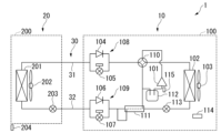
- FIG. 1 is a refrigerant circuit diagram showing the configuration of an air conditioner 1 in a first embodiment of this disclosure.
- the air conditioner 1 includes a heat source side unit 10, a usage side unit 20, and a refrigerant pipe 30.
- the heat source side unit 10 serves as a heat source during heating operation, and serves as a cold heat source during cooling operation.
- the heat source side unit 10 includes a casing 100, a compressor 101, a four-way valve (four-way switching valve) 110, a heat source side heat exchanger 102, a fan 103, a heat source side expansion valve 113, a double pipe 111, a liquid side cutoff mechanism 109, It has a gas side shutoff mechanism 108, a pressure vessel 112, a control section 114, a refrigerant pressure acquisition section 115, and piping that connects the components.
- the casing 100 houses the components of the heat source side unit 10.
- Compressor 101 compresses low pressure gas refrigerant and discharges high pressure gas refrigerant.
- Low pressure gas refrigerant flows from pressure vessel 112 toward compressor 101 .
- High pressure gas refrigerant flows from compressor 101 toward four-way valve 110 .
- the four-way valve 110 switches between the refrigerant circuit configuration for cooling operation and the refrigerant circuit configuration for heating operation.
- the four-way valve 110 makes the connection shown by the solid line in FIG.
- the refrigerant thereby flows in the direction of the arrow in FIG. That is, during cooling operation, the refrigerant discharged from the compressor 101 flows toward the heat source side heat exchanger 102.
- the four-way valve 110 makes the connection shown by the solid line in FIG.
- the refrigerant flows in the direction of the arrow in FIG. That is, during heating operation, the refrigerant discharged from the compressor 101 flows toward the gas-side shutoff mechanism 108.
- the four-way valve 110 has a refrigerant circuit configuration for heating operation when it is energized, and has a refrigerant circuit configuration for cooling operation when it is not energized, but the reverse may be possible.
- the heat source side heat exchanger 102 exchanges heat between the refrigerant and air (outside air).
- the heat source side heat exchanger 102 radiates heat to the air and becomes a heat source during cooling operation, and absorbs heat from the air and becomes a cold heat source during heating operation.
- the fan 103 promotes heat exchange between the refrigerant and air by the heat source side heat exchanger 102.
- the heat source side expansion valve 113 is a valve whose opening degree can be adjusted.
- the double tube 111 is, for example, a tube formed by processing a copper plate into a double tube shape.
- the double pipe 111 facilitates heat exchange between the refrigerant flowing through the outer pipe and the refrigerant flowing through the inner pipe.
- the liquid-side shutoff mechanism 109 is disposed in the liquid-side refrigerant piping 32, and when energized, allows the refrigerant to flow in both directions, and when not energized, it allows the refrigerant to flow from the user-side unit 20 (user-side heat exchanger 201) side to the heat source. Only the flow of refrigerant to the side unit 10 (heat source side heat exchanger 102) is allowed.
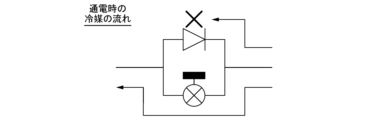
- the liquid-side blocking mechanism 109 may have a configuration in which a liquid-side check valve 106 and a liquid-side solenoid valve 107 are arranged in parallel, as shown in FIG.
- the liquid-side shutoff mechanism 109 may be any shutoff mechanism 700 that has a function equivalent to that of a check valve 701 and a solenoid valve 702 arranged in parallel as shown in FIG.
- the liquid side shutoff mechanism 109 may be a single solenoid valve having an equivalent function, or, like the shutoff mechanism 800 shown in FIG. 803 may be arranged in parallel.
- the direction of flow allowed by check valve 801 is opposite to the direction of flow allowed by check valve 802.
- the liquid side shutoff mechanism 109 is for opening or closing the refrigerant path.
- the liquid side blocking mechanism 109 seals off the refrigerant sealed in the heat source side unit 10 to prevent it from leaking to the user side unit 20 and the outside, for example.
- the liquid-side solenoid valve 107 that constitutes the liquid-side cutoff mechanism 109 is a normally closed type solenoid valve.
- the liquid-side solenoid valve 107 constituting the liquid-side shutoff mechanism 109 has a coil 501, a magnet 502, a needle 503, a valve seat 504, and conduits 505, 506, as shown, for example, in a solenoid valve (shutoff valve) 50 in FIG. .
- the needle 503 is maintained away from the valve seat 504 by the coil 501. This allows the refrigerant to flow between conduit 505 and conduit 506. Therefore, as shown in FIG. 5, the refrigerant flows from the heat source side unit 10 to the user side unit 20 via the liquid side electromagnetic valve 107 that constitutes the liquid side cutoff mechanism 109, and the refrigerant path during cooling operation indicated by the arrow in FIG. Realize.
- the control unit 114 when the control unit 114 is not energizing the coil included in the liquid-side solenoid valve 107, the needle 503 is maintained in close contact with the valve seat 504. As a result, the refrigerant cannot flow between the pipe line 505 and the pipe line 506. Therefore, as shown in FIG. 6, the refrigerant flows from the user side unit 20 to the heat source side unit 10 via the liquid side check valve 106 that constitutes the liquid side shutoff mechanism 109, and the refrigerant path during heating operation is indicated by the arrow in FIG. Realize.
- the gas side shutoff mechanism 108 is arranged in the gas side refrigerant piping 31, and when energized, allows the refrigerant to flow in both directions, and when not energized, the gas side shutoff mechanism 108 allows the refrigerant to flow from the user side unit 20 (user side heat exchanger 201) side to the heat source. Only the flow of refrigerant to the side unit 10 (heat source side heat exchanger 102) is allowed.
- the gas-side shutoff mechanism 108 may have a configuration in which a gas-side check valve 104 and a gas-side solenoid valve 105 are arranged in parallel, as shown in FIG.
- the gas-side shutoff mechanism 108 may be any shutoff mechanism 700 that has a function equivalent to that of a check valve 701 and a solenoid valve 702 arranged in parallel as shown in FIG.
- the gas side shutoff mechanism 108 may be a single solenoid valve having an equivalent function, or, like the shutoff mechanism 800 shown in FIG. 803 may be arranged in parallel.
- the direction of flow allowed by check valve 801 is opposite to the direction of flow allowed by check valve 802.
- the gas side shutoff mechanism 108 is for opening or closing the refrigerant path. In order to prevent the refrigerant sealed in the heat source side unit 10 from leaking to the user side unit 20 and the outside when the air conditioner 1 is installed, the gas side shutoff mechanism 108 seals off the refrigerant.
- the gas side solenoid valve 105 that constitutes the gas side shutoff mechanism 108 is a normally closed type solenoid valve.
- the gas side electromagnetic valve 105 constituting the gas side shutoff mechanism 108 has a coil 501, a magnet 502, a needle 503, a valve seat 504, and conduits 505 and 506 as shown in FIG. 2, for example.
- the needle 503 is maintained away from the valve seat 504 by the coil 501. This allows the refrigerant to flow between conduit 505 and conduit 506. Therefore, as shown in FIG. 5, the refrigerant flows from the heat source side unit 10 to the user side unit 20 via the gas side solenoid valve 105 that constitutes the gas side shutoff mechanism 108, and the refrigerant path during the heating operation indicated by the arrow in FIG. Realize.
- the control unit 114 when the control unit 114 is not energizing the coil included in the gas-side solenoid valve 105, the needle 503 is maintained in close contact with the valve seat 504. As a result, the refrigerant cannot flow between the pipe line 505 and the pipe line 506. Therefore, as shown in FIG. 6, the refrigerant flows from the user side unit 20 to the heat source side unit 10 via the gas side check valve 104 constituting the gas side shutoff mechanism 108, and the refrigerant path during cooling operation is indicated by the arrow in FIG. Realize.
- the pressure vessel 112 functions as a container for storing, for example, low-pressure refrigerant flowing through the air conditioner 1.
- the control unit 114 receives output signals from various sensors provided in the heat source side unit 10 and the usage side unit 20 and the refrigerant leak detection unit 204. These various sensors may include sensors not shown.
- the control unit 114 drives the compressor 101, the four-way valve 110, the fan 103, the heat source side expansion valve 113, and other actuators (not shown).
- the refrigerant piping 30 includes piping that connects the heat source side unit 10 and the usage side unit 20, and connects the heat source side heat exchanger 102 and the usage side heat exchanger 201.
- the refrigerant pipe 30 has a gas side refrigerant pipe 31 and a liquid side refrigerant pipe 32.
- a gas-side shutoff mechanism 108 is arranged in the gas-side refrigerant pipe 31 .
- a liquid-side shutoff mechanism 109 is arranged in the liquid-side refrigerant pipe 32 .
- the gas-side shutoff mechanism 108 and the liquid-side shutoff mechanism 109 are arranged inside the heat source side unit 10, but they may be arranged inside the usage side unit 20.
- the user-side unit 20 provides cold heat during cooling and heat during heating.
- the user unit 20 that constitutes the air conditioner 1 generates cold air or warm air to adjust the indoor temperature.
- the user unit 20 includes a casing 200, a user heat exchanger 201, a fan 202, and a user expansion valve 203.
- the casing 200 houses the components of the user unit 20.
- the user-side heat exchanger 201 exchanges heat between refrigerant and air.
- the user-side heat exchanger 201 absorbs heat and becomes a source of cold heat during cooling operation, and radiates heat and becomes a heat source during heating operation.
- the fan 202 facilitates heat exchange between the refrigerant and air by the user-side heat exchanger 201.
- the fan 202 blows out the air that has undergone heat exchange from the casing 200 into the room.
- the utilization side expansion valve 203 is a valve whose opening degree can be adjusted.
- the refrigerant leakage detection unit 204 is a sensor that detects refrigerant leakage.
- the refrigerant leak detection section 204 is installed in the air-conditioned space of the user unit 20, but may be provided inside the casing 200.
- refrigerant used in the air conditioner 1 examples include fluorine-based refrigerants or hydrocarbon-based refrigerants that have a low global warming potential (GWP).
- GWP global warming potential
- R1123 examples include fluorine-based refrigerants or hydrocarbon-based refrigerants that have a low global warming potential (GWP).
- R1234yf, R1234ze, R32, or R290 or a mixture of two or more of these refrigerants, or a refrigerant mixture of any of these and other refrigerants, or a refrigerant mixture containing R1132(E).
- R516A R445A, R444A, R454C, R444B, R454A, R455A, R457A, R459B, R452B, R454B, R447B, R447A, R446A, and R459A.
- the refrigerant causes a reaction that involves a phase change such as condensation and evaporation, but it is not necessarily necessary that the refrigerant involves a phase change as long as heat exchange is performed.
- the four-way valve 110 of the heat source side unit 10 makes the connection shown by the solid line in FIG. Further, the liquid side solenoid valve 107 is in an open state, and the gas side solenoid valve 105 is in a closed state.
- the high-pressure gas refrigerant discharged from the compressor 101 passes through the four-way valve 110 and is radiated and condensed in the heat source side heat exchanger 102 to become high-pressure liquid refrigerant.
- the high-pressure liquid refrigerant passes through the heat source side expansion valve 113 and the double pipe 111 and reaches the liquid side cutoff mechanism 109.
- the high-pressure liquid refrigerant enters the user-side unit 20 via the liquid-side solenoid valve 107 of the liquid-side shutoff mechanism 109 and the liquid-side refrigerant piping 32.
- the high-pressure liquid refrigerant is depressurized by the usage-side expansion valve 203 and becomes a low-pressure gas-liquid two-phase refrigerant.
- the low-pressure gas-liquid two-phase refrigerant absorbs heat and evaporates in the user-side heat exchanger 201 to become a low-pressure gas refrigerant.
- the low-pressure gas refrigerant enters the heat source unit 10 through the gas-side refrigerant pipe 31, passes through the gas-side check valve 104 of the gas-side shutoff mechanism 108, the four-way valve 110, and the pressure vessel 112, and is sucked into the compressor 101. .
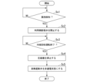
- FIG. 9 is a flowchart illustrating control during cooling operation by the control unit 114 in this embodiment.
- the control unit 114 de-energizes both the liquid-side shutoff mechanism 109 and the gas-side shutoff mechanism 108.
- step Sa1 the control unit 114 starts the compressor 101.
- step Sa2 the control unit 114 starts energizing the coil of the liquid-side solenoid valve 107 that constitutes the liquid-side cutoff mechanism 109, and opens the liquid-side solenoid valve 107.
- Step Sa1 and step Sa2 may be performed at the same timing or may be performed in the reverse order.
- step Sa3 the control unit 114 checks whether a cooling operation stop signal has been received. When the control unit 114 has not received the cooling operation stop signal (step Sa3-No), the control unit 114 performs step Sa3 again. When the control unit 114 receives the cooling operation stop signal, that is, when the cooling operation ends (step Sa3-Yes), the process proceeds to step Sa4. In step Sa4, the control unit 114 stops the compressor 101. In step Sa5, the control unit 114 obtains the time T after receiving the cooling operation stop signal.
- step Sa6 the control unit 114 determines the elapsed time.
- the control unit 114 compares the time T after receiving the acquired cooling operation stop signal with a predetermined threshold T1. When the time T is less than the threshold T1 (step Sa6-No), the control unit 114 performs step Sa5 again. When the time T is equal to or greater than the threshold value T1 (step Sa6-Yes), the control unit 114 proceeds to step Sa7.
- step Sa7 the control unit 114 stops energizing the coil of the liquid-side solenoid valve 107 that constitutes the liquid-side cutoff mechanism 109, and closes the liquid-side solenoid valve 107. As a result, the supply of refrigerant to the user unit 20 is stopped.
- the four-way valve 110 of the heat source side unit 10 makes the connection shown by the solid line in FIG. 4 . Further, the liquid side solenoid valve 107 is in a closed state, and the gas side solenoid valve 105 is in an open state.
- the high-pressure gas refrigerant discharged from the compressor 101 passes through the four-way valve 110 and reaches the gas-side shutoff mechanism 108 .
- the high-pressure gas refrigerant enters the user-side unit 20 through the gas-side solenoid valve 105 of the gas-side shutoff mechanism 108 and the gas-side refrigerant pipe 31, and is heat-radiated and condensed in the user-side heat exchanger 201 to become a high-pressure liquid refrigerant.
- the high-pressure liquid refrigerant passes through the user-side expansion valve 203, the liquid-side refrigerant pipe 32, the liquid-side check valve 106 of the liquid-side cutoff mechanism 109, and the double pipe 111, and reaches the heat source-side expansion valve 113.
- the high-pressure liquid refrigerant is reduced in pressure by the user-side expansion valve 203, the heat source-side expansion valve 113, or both the user-side expansion valve 203 and the heat source-side expansion valve 113, and becomes a low-pressure gas-liquid two-phase refrigerant.
- the low-pressure gas-liquid two-phase refrigerant absorbs heat and evaporates in the heat source side heat exchanger 102 to become a low-pressure gas refrigerant.
- the low pressure gas refrigerant passes through the four-way valve 110 and is sucked into the compressor 101.
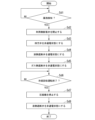
- FIG. 10 is a flowchart illustrating control during heating operation by the control unit 114 in this embodiment.
- the control unit 114 de-energizes both the liquid-side shutoff mechanism 109 and the gas-side shutoff mechanism 108.
- step Sb1 the control unit 114 starts the compressor 101.
- step Sb2 the control unit 114 energizes the four-way valve 110 to open it.
- the four-way valve 110 enters the state shown by the solid line in FIG. 4, and the refrigerant discharged from the compressor 101 flows to the gas-side shutoff mechanism 108 via the four-way valve 110.
- step Sb3 the control unit 114 starts energizing the coil of the gas-side solenoid valve 105 that constitutes the gas-side shutoff mechanism 108, and opens the gas-side solenoid valve 105.
- Steps Sb1 to Sb3 may be performed at the same timing or may be performed in a different order from that in FIG.
- step Sb4 the control unit 114 checks whether a heating operation stop signal has been received. When the control unit 114 has not received the heating operation stop signal (step Sb4-No), it performs step Sb4 again. When the control unit 114 receives the heating operation stop signal, that is, when the heating operation ends (step Sb4-Yes), the process proceeds to step Sb5. In step Sb5, the control unit 114 stops the compressor 101. In step Sb6, the control unit 114 acquires the time T after receiving the heating operation stop signal.
- step Sb7 the elapsed time is determined.
- the control unit 114 compares the time T after receiving the acquired heating operation stop signal with a predetermined threshold T2. When the time T is less than the threshold T2 (step Sb7-No), the control unit 114 performs step Sb6 again. When the time T is equal to or greater than the threshold T2 (step Sb7-Yes), the control unit 114 proceeds to step Sb8.
- the threshold value T2 ( ⁇ 0) may be a shorter time than the threshold value T1 at the end of the cooling operation.
- the flowchart of FIG. 10 may not include steps Sb6 and Sb7, and the control unit 114 may proceed to step Sb8 after stopping the compressor 101 in step Sb5.
- step Sb8 the control unit 114 stops energizing the coil of the gas-side solenoid valve 105 that constitutes the gas-side shutoff mechanism 108, and closes the gas-side solenoid valve 105. As a result, the supply of refrigerant to the user unit 20 is stopped.
- step Sb9 the control unit 114 stops energizing the four-way valve 110 to close it. As a result, the four-way valve 110 enters the state shown by the solid line in FIG. Step Sb8 and step Sb9 may be performed at the same timing, or may be performed in a different order from that in FIG.
- Refrigerant recovery operation When the control unit 114 receives information on a refrigerant leak from the refrigerant leak detection unit 204 installed in the air-conditioned space of the user unit 20, the control unit 114 switches the four-way valve 110 to a refrigerant circuit configuration for cooling operation and shuts off the liquid side.
- a refrigerant recovery operation is performed in which the refrigerant is recovered from the user unit 20 by opening the mechanism 109 (energized state) and closing the gas-side shutoff mechanism 108 (de-energized state).
- the four-way valve 110 of the heat source side unit 10 makes the connection shown by the solid line in FIG.
- the high-pressure gas refrigerant discharged from the compressor 101 passes through the four-way valve 110 and is radiated and condensed in the heat source side heat exchanger 102 to become high-pressure liquid refrigerant.
- the high-pressure liquid refrigerant passes through the heat source side expansion valve 113 and the double pipe 111 and reaches the liquid side cutoff mechanism 109.
- the high-pressure liquid refrigerant enters the user-side unit 20 via the liquid-side solenoid valve 107 of the liquid-side shutoff mechanism 109 and the liquid-side refrigerant piping 32.
- the high-pressure liquid refrigerant is depressurized by the usage-side expansion valve 203 and becomes a low-pressure gas-liquid two-phase refrigerant.
- the low-pressure gas-liquid two-phase refrigerant absorbs heat and evaporates in the user-side heat exchanger 201 to become a low-pressure gas refrigerant.
- the low-pressure gas refrigerant enters the heat source unit 10 through the gas-side refrigerant pipe 31, passes through the gas-side check valve 104 of the gas-side shutoff mechanism 108, the four-way valve 110, and the pressure vessel 112, and is sucked into the compressor 101. .
- FIG. 11 is a flowchart illustrating control in which the air conditioner 1 in this embodiment shifts from cooling operation to refrigerant recovery operation.
- the control unit 114 checks whether the refrigerant leak detection unit 204 has detected a refrigerant leak. When the refrigerant leak detection unit 204 does not detect a refrigerant leak (step Sc1-No), the control unit 114 performs step Sc1 again. When the refrigerant leak detection section 204 detects a refrigerant leak or when the control section 114 determines that there is a refrigerant leak (step Sc1-Yes), the control section 114 proceeds to step Sc2. In step Sc2, the control unit 114 closes the usage-side expansion valve 203. The closed state of the usage-side expansion valve 203 is a state in which the usage-side expansion valve 203 does not allow refrigerant to pass through.
- Step Sc3 is an end determination process.
- the control unit 114 determines whether or not to end the refrigerant recovery operation. When it is not determined that the refrigerant recovery operation is to be ended (step Sc3-No), the control unit 114 performs step Sc3 again. When determining that the refrigerant recovery operation is to be ended (step Sc3-Yes), the control unit 114 proceeds to step Sc4.
- step Sc4 the control unit 114 stops the compressor 101.
- step Sc5 the control unit 114 stops energizing the coil of the liquid-side solenoid valve 107 that constitutes the liquid-side cutoff mechanism 109, and closes the liquid-side solenoid valve 107. As a result, the supply of refrigerant to the user unit 20 is stopped. Steps Sc4 to Sc5 may be performed at the same timing or may be performed in a different order from that in FIG. 11.
- FIG. 12 is a flowchart illustrating control in which the air conditioner 1 in this embodiment shifts from heating operation to refrigerant recovery operation.
- the control unit 114 checks whether the refrigerant leak detection unit 204 has detected a refrigerant leak. When the refrigerant leakage detection unit 204 does not detect a refrigerant leakage (step Sd1-No), the control unit 114 performs step Sd1 again. When the refrigerant leak detection section 204 detects a refrigerant leak or when the control section 114 determines that there is a refrigerant leak (step Sd1-Yes), the control section 114 proceeds to step Sd2.
- step Sd2 the control unit 114 closes the usage-side expansion valve 203.
- step Sd3 the control unit 114 stops energizing the four-way valve 110 to bring it into a closed state.
- step Sd4 the control unit 114 starts energizing the coil of the liquid-side solenoid valve 107 that constitutes the liquid-side cutoff mechanism 109, and opens the liquid-side solenoid valve 107.
- step Sd5 the control unit 114 stops energizing the coil of the gas-side solenoid valve 105 that constitutes the gas-side cutoff mechanism 108, and closes the gas-side solenoid valve 105. Steps Sd2 to Sd5 may be performed at the same timing, or may be performed in a different order from that in FIG. 12.
- Step Sd6 is an end determination process.
- the control unit 114 determines whether or not to end the refrigerant recovery operation. When it is not determined that the refrigerant recovery operation is to be ended (step Sd6-No), the control unit 114 performs step Sd6 again. When determining that the refrigerant recovery operation is to be ended (step Sd6-Yes), the control unit 114 proceeds to step Sd7.
- step Sd7 the control unit 114 stops the compressor 101.
- step Sd8 the control unit 114 stops energizing the coil of the liquid-side solenoid valve 107 that constitutes the liquid-side cutoff mechanism 109, and closes the liquid-side solenoid valve 107. As a result, the supply of refrigerant to the user unit 20 is stopped. Steps Sd7 to Sd8 may be performed at the same timing, or may be performed in a different order from that in FIG. 12.
- FIG. 13 is a flowchart illustrating control in which the air conditioner 1 according to the present embodiment shifts from a stop state to a refrigerant recovery operation.
- the control unit 114 checks whether the refrigerant leak detection unit 204 has detected a refrigerant leak. When the refrigerant leakage detection unit 204 does not detect refrigerant leakage (step Se1-No), the control unit 114 performs step Se1 again. When the refrigerant leak detection section 204 detects a refrigerant leak or when the control section 114 determines that there is a refrigerant leak (step Se1-Yes), the control section 114 proceeds to step Se2.
- step Se2 the control unit 114 starts the compressor 101.
- step Se3 the control unit 114 closes the usage-side expansion valve 203.
- step Se4 the control unit 114 stops energizing the four-way valve 110 to configure the refrigerant circuit for cooling operation.
- step Se5 the control unit 114 starts energizing the coil of the liquid-side solenoid valve 107 that constitutes the liquid-side cutoff mechanism 109, and opens the liquid-side solenoid valve 107.
- step Se6 the control unit 114 stops energizing the coil of the gas-side solenoid valve 105 that constitutes the gas-side cutoff mechanism 108, and closes the gas-side solenoid valve 105.
- Steps Se2 to Step Se6 may be performed at the same timing or may be performed in a different order from that in FIG. 13.
- Step Se7 is an end determination process.
- the control unit 114 determines whether or not to end the refrigerant recovery operation. When it is not determined that the refrigerant recovery operation is to be ended (step Se7-No), the control unit 114 performs step Se7 again. When determining that the refrigerant recovery operation is to be ended (step Se7-Yes), the control unit 114 proceeds to step Se8.
- step Se8 the control unit 114 stops the compressor 101.
- step Se9 the control unit 114 stops energizing the coil of the liquid-side solenoid valve 107 that constitutes the liquid-side cutoff mechanism 109, and closes the liquid-side solenoid valve 107. As a result, the supply of refrigerant to the user unit 20 is stopped. Steps Se8 to Step Se9 may be performed at the same timing or may be performed in a different order from that in FIG. 13.
- the air conditioner 1 in this embodiment does not need to keep both the gas side solenoid valve 105 and the liquid side solenoid valve 107 energized during normal cooling or heating operation, and only one of them can be energized.
- the refrigerant can be circulated through the refrigerant circuit. Therefore, compared to the case of a solenoid valve that requires constant energization during operation to open the solenoid valve, the time that each solenoid valve is energized is shortened, and the number of times the solenoid valve is switched from the open state to the closed state is reduced. Thereby, shortening of the life span of the coils and valve seats of the gas side solenoid valve 105 and the liquid side solenoid valve 107 can be suppressed.
- the gas-side solenoid valve 105 that constitutes the gas-side shutoff mechanism 108 and the liquid-side solenoid valve 107 that constitutes the liquid-side shutoff mechanism 109 are normally closed type solenoid valves. It has a function that closes the refrigerant path when the power is off, such as during a stoppage or power outage. Therefore, the gas side solenoid valve 105 and the liquid side solenoid valve 107 can block the movement of refrigerant from the heat source side unit 10 to the usage side unit 20.
- FIG. 14 is a refrigerant circuit diagram showing the configuration of the air conditioner 1 in the second embodiment of this disclosure.
- the air conditioner 1 includes a heat source side unit 10, usage side units 20, 20-a, refrigerant piping 30, and a valve unit 40. Note that although two usage-side units 20 and 20-a are connected in FIG. 14, three or more usage-side units may be connected to the valve unit 40.
- the valve unit 40 has a casing 400 and usage-side expansion valves 203 and 203-a.
- the heat source side unit 10 has the same configuration as that in FIG. 1, so the explanation will be omitted.
- the usage side unit 20 is the same as that shown in FIG. 1 except that the usage side expansion valve 203 is included in the valve unit 40, so the description thereof will be omitted.
- the user unit 20-a has the same configuration as the user unit 20, so a description thereof will be omitted.
- the basic operation of the refrigeration cycle of the air conditioner 1 in this embodiment is the same as that in the first embodiment. Note that the opening degrees of the usage-side expansion valves 203 and 203-a may be adjusted individually in correspondence with the respective usage-side units 20 and 20-a.
- the refrigerant cutoff and refrigerant recovery operation are the same as in the first embodiment. perform an action. Note that the same operation may be performed when the refrigerant leak detection section 204-a of the user-side unit 20-a leaks refrigerant.
- FIG. 15 is a refrigerant circuit diagram showing another configuration example of the air conditioner 1 in this embodiment. 15, the air conditioner 1 differs from FIG. 14 in that the air conditioner 1 does not include the valve unit 40, and the usage-side expansion valves 203 and 203-a are provided in the usage-side units 20 and 20-a, respectively. , otherwise the same.
- the gas-side solenoid valve 105 that constitutes the gas-side shutoff mechanism 108 and the liquid-side solenoid valve 107 that constitutes the liquid-side shutoff mechanism 109 are normally closed type solenoid valves. It has a function that closes the refrigerant path when the power is off, such as during a stoppage or power outage. Therefore, the gas side solenoid valve 105 and the liquid side solenoid valve 107 can block the movement of refrigerant from the heat source side unit 10 to the usage side unit 20, 20-a.
- the pressure of the refrigerant sucked into the compressor 101 acquired by the refrigerant pressure acquisition unit 115 is used to determine whether to shift to the refrigerant recovery operation.
- the configuration of the air conditioner 1 in this embodiment is the same as that in FIG. 1, so the description will be omitted.
- the configuration of the air conditioner 1 may be the same as that shown in FIGS. 14 and 15.
- the control unit 114 may perform the same control as the usage-side expansion valve 203 on the usage-side expansion valve 203-a.
- the basic operation of the refrigeration cycle of the air conditioner 1 is the same as that in the first embodiment, the explanation will be omitted.
- the control unit 114 in this embodiment compares the pressure P acquired by the refrigerant pressure acquisition unit 115 with a predetermined threshold value P1, and when the pressure P is less than the threshold value P1, determines that the pressure is abnormal and recovers the refrigerant. Shift to driving. Note that the control unit 114 may determine that the operation is abnormal using a value obtained from a sensor (not shown), and may shift to the refrigerant recovery operation.
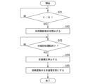
- FIG. 16 is a flowchart illustrating control in which the air conditioner 1 shifts from cooling operation to refrigerant recovery operation in the third embodiment of this disclosure.
- the control unit 114 determines whether there is a pressure abnormality.
- the control unit 114 compares the pressure P acquired by the refrigerant pressure acquisition unit 115 with a threshold value P1. When the pressure P is equal to or greater than the threshold value P1 (step Sf1-No), the control unit 114 performs step Sf1 again. When the pressure P is less than the threshold P1 (step Sf1-Yes), the control unit 114 proceeds to step Sf2. In step Sf2, the control unit 114 closes the usage-side expansion valve 203.
- Step Sf3 is an end determination process.
- the control unit 114 determines whether or not to end the refrigerant recovery operation. When it is not determined that the refrigerant recovery operation is to be ended (step Sf3-No), the control unit 114 performs step Sf3 again. When determining that the refrigerant recovery operation is to be ended (step Sf3-Yes), the control unit 114 proceeds to step Sf4.
- the control unit 114 stops the compressor 101.
- step Sf5 the control unit 114 stops energizing the coil of the liquid-side solenoid valve 107 that constitutes the liquid-side cutoff mechanism 109, and closes the liquid-side solenoid valve 107. As a result, the supply of refrigerant to the user unit 20 is stopped. Steps Sf4 to Sf5 may be performed at the same timing, or may be performed in a different order from that in FIG. 16.
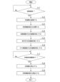
- FIG. 17 is a flowchart illustrating control in which the air conditioner 1 in this embodiment shifts from heating operation to refrigerant recovery operation.
- the control unit 114 determines whether there is a pressure abnormality.
- the control unit 114 compares the pressure P acquired by the refrigerant pressure acquisition unit 115 with a threshold value P1. When the pressure P is equal to or greater than the threshold value P1 (step Sg1-No), the control unit 114 performs step Sg1 again. When the pressure P is less than the threshold P1 (step Sg1-Yes), the control unit 114 proceeds to step Sg2.
- step Sg2 the control unit 114 closes the usage-side expansion valve 203.
- step Sg3 the control unit 114 stops the power supply to the four-way valve 110 to configure the refrigerant circuit for cooling operation.
- step Sg4 the control unit 114 starts energizing the coil of the liquid-side solenoid valve 107 that constitutes the liquid-side cutoff mechanism 109, and opens the liquid-side solenoid valve 107.
- step Sg5 the control unit 114 stops energizing the coil of the gas-side solenoid valve 105 that constitutes the gas-side cutoff mechanism 108, and closes the gas-side solenoid valve 105. Steps Sg2 to Sg5 may be performed at the same timing or may be performed in a different order from that in FIG. 17.
- Step Sg6 is an end determination process.
- the control unit 114 determines whether or not to end the refrigerant recovery operation. When it is not determined that the refrigerant recovery operation is to be ended (step Sg6-No), the control unit 114 performs step Sg6 again. When determining that the refrigerant recovery operation is to be ended (step Sg6-Yes), the control unit 114 proceeds to step Sg7.
- step Sg7 the control unit 114 stops the compressor 101.
- step Sg8 the control unit 114 stops energizing the coil of the liquid-side solenoid valve 107 that constitutes the liquid-side cutoff mechanism 109, and closes the liquid-side solenoid valve 107. As a result, the supply of refrigerant to the user unit 20 is stopped. Steps Sg7 to Sg8 may be performed at the same timing or may be performed in a different order from that in FIG. 17.
- FIG. 18 is a flowchart illustrating control in which the air conditioner 1 according to the present embodiment shifts from stop to refrigerant recovery operation.
- the control unit 114 determines whether there is a pressure abnormality.
- the control unit 114 compares the pressure P acquired by the refrigerant pressure acquisition unit 115 with a threshold value P1. When the pressure P is equal to or greater than the threshold value P1 (step Sh1-No), the control unit 114 performs step Sh1 again. When the pressure P is less than the threshold P1 (step Sh1-No), the control unit 114 proceeds to step Sh2.
- step Sh2 the control unit 114 starts the compressor 101.
- step Sh3 the control unit 114 closes the usage-side expansion valve 203.
- step Sh4 the control unit 114 stops the power supply to the four-way valve 110 to configure the refrigerant circuit for cooling operation.
- step Sh5 the control unit 114 starts energizing the coil of the liquid-side solenoid valve 107 that constitutes the liquid-side cutoff mechanism 109, and opens the liquid-side solenoid valve 107.
- step Sh6 the control unit 114 stops energizing the coil of the gas-side solenoid valve 105 that constitutes the gas-side cutoff mechanism 108, and closes the gas-side solenoid valve 105.
- Steps Sh2 to Sh6 may be performed at the same timing or may be performed in a different order from that in FIG. 17.
- Step Sh7 is an end determination process.
- the control unit 114 determines whether or not to end the refrigerant recovery operation. When it is not determined that the refrigerant recovery operation is to be ended (step Sh7-No), the control unit 114 performs step Sh6 again. When it is determined that the refrigerant recovery operation is to be ended (step Sh7-Yes), the control unit 114 proceeds to step Sh8.
- step Sh8 the control unit 114 stops the compressor 101.
- step Sh9 the control unit 114 stops energizing the coil of the liquid-side solenoid valve 107 that constitutes the liquid-side cutoff mechanism 109, and closes the liquid-side solenoid valve 107. As a result, the supply of refrigerant to the user unit 20 is stopped. Steps Sh8 to Sh9 may be performed at the same timing, or may be performed in a different order from that in FIG. 17.
- the air conditioner 1 does not need to keep both the gas side solenoid valve 105 and the liquid side solenoid valve 107 energized during normal cooling or heating operation.
- refrigerant can be circulated in the refrigerant circuit by energizing only one of them. Therefore, compared to the case of a solenoid valve that requires constant energization during operation to open, it is possible to suppress shortening of the life of the coils and valve seats of the gas side solenoid valve 105 and the liquid side solenoid valve 107.
- the gas-side solenoid valve 105 that constitutes the gas-side shutoff mechanism 108 and the liquid-side solenoid valve 107 that constitutes the liquid-side shutoff mechanism 109 are normally closed type solenoid valves. It has a function that closes the refrigerant path when the power is off, such as during a stoppage or power outage. Therefore, the gas side solenoid valve 105 and the liquid side solenoid valve 107 can block the movement of refrigerant from the heat source side unit 10 to the usage side unit 20.
- ⁇ Fourth embodiment> In the first embodiment, when refrigerant leakage is detected, the usage-side expansion valve 203 is closed, a refrigerant recovery operation is performed, and the recovered refrigerant is also stored in the liquid-side refrigerant pipe 32. In the fourth embodiment, when refrigerant leakage is detected, the utilization side expansion valve 203 is opened, and the refrigerant is also recovered from the liquid side refrigerant pipe 32.
- the configuration of the air conditioner 1 in this embodiment is the same as that in FIG. 1, so the description will be omitted. Note that the configuration of the air conditioner 1 may be the same as that shown in FIGS. 14 and 15.
- control unit 114 may perform the same control as the usage-side expansion valve 203 on the usage-side expansion valve 203-a. Moreover, since the basic operation of the refrigeration cycle of the air conditioner 1 is the same as that in the first embodiment, the explanation will be omitted.
- FIG. 19 is a flowchart illustrating control in which the air conditioner 1 in this embodiment shifts from heating operation to refrigerant recovery operation.
- the control unit 114 checks whether the refrigerant leak detection unit 204 has detected a refrigerant leak. When the refrigerant leakage detection unit 204 does not detect a refrigerant leakage (step Si1-No), the control unit 114 performs step Si1 again. When the refrigerant leak detection section 204 detects a refrigerant leak or when the control section 114 determines that there is a refrigerant leak (step Si1-Yes), the control section 114 proceeds to step Si2.
- step Si2 the control unit 114 fully opens the usage-side expansion valve 203.
- the fully open state is an open state in which the change in refrigerant pressure before and after the usage-side expansion valve 203 is minimized.
- it is desirable to set the fully open state but instead of the fully open state, it may be set to an open state in which the refrigerant has a predetermined pressure change before and after the usage-side expansion valve 203.
- the control unit 114 stops energizing the coil of the liquid-side solenoid valve 107 that constitutes the liquid-side cutoff mechanism 109, and closes the liquid-side solenoid valve 107.
- step Si4 the control unit 114 stops energizing the four-way valve 110 to close it.
- step Si5 the control unit 114 stops energizing the coil of the gas-side solenoid valve 105 that constitutes the gas-side cutoff mechanism 108, and closes the gas-side solenoid valve 105.
- Steps Si2 to Step Si5 may be performed at the same timing or may be performed in a different order from that in FIG. 19.
- Step Si6 is an end determination process.
- the control unit 114 determines whether or not to end the refrigerant recovery operation. When it is not determined that the refrigerant recovery operation is to be ended (step Si6-No), the control unit 114 performs step Si6 again. When determining that the refrigerant recovery operation is to be ended (step Si6-Yes), the control unit 114 proceeds to step Si7.
- step Si7 the control unit 114 stops the compressor 101.
- step Si8 the control unit 114 closes the usage-side expansion valve. Steps Si7 to Step Si8 may be performed at the same timing, or may be performed in a different order from that in FIG.
- FIG. 20 is a flowchart illustrating control in which the air conditioner 1 according to the present embodiment shifts from a stop state to a refrigerant recovery operation.
- the control unit 114 checks whether the refrigerant leak detection unit 204 has detected a refrigerant leak. When the refrigerant leakage detection unit 204 does not detect refrigerant leakage (step Sj1-No), the control unit 114 performs step Sj1 again. When the refrigerant leak detection section 204 detects a refrigerant leak or when the control section 114 determines that there is a refrigerant leak (step Sj1-Yes), the control section 114 proceeds to step Sj2.
- step Sj2 the control unit 114 starts the compressor 101.
- step Sj3 the control unit 114 fully opens the usage-side expansion valve 203.
- the control unit 114 stops energizing the coil of the liquid-side solenoid valve 107 that constitutes the liquid-side cutoff mechanism 109, and closes the liquid-side solenoid valve 107.
- step Sj5 the control unit 114 stops energizing the four-way valve 110 to configure the refrigerant circuit for cooling operation.
- step Sj6 the control unit 114 stops energizing the coil of the gas-side solenoid valve 105 that constitutes the gas-side cutoff mechanism 108, and closes the gas-side solenoid valve 105.
- Steps Sj2 to Sj6 may be performed at the same timing or may be performed in a different order from that in FIG. 20.
- Step Sj7 is an end determination process.
- the control unit 114 determines whether or not to end the refrigerant recovery operation. When it is not determined that the refrigerant recovery operation is to be ended (step Sj7-No), the control unit 114 performs step Sj7 again. When determining that the refrigerant recovery operation is to be ended (step Sj7-Yes), the control unit 114 proceeds to step Sj8.
- step Sj8 the control unit 114 stops the compressor 101.
- step Sj9 the control unit 114 closes the usage-side expansion valve 203. As a result, the supply of refrigerant to the user unit 20 is stopped. Steps Sj8 to Sj9 may be performed at the same timing, or may be performed in a different order from that in FIG. 20.
- FIG. 21 is a flowchart illustrating control in which the air conditioner 1 in this embodiment shifts from cooling operation to refrigerant recovery operation.
- the control unit 114 checks whether the refrigerant leak detection unit 204 has detected a refrigerant leak. When the refrigerant leak detection unit 204 does not detect a refrigerant leak (step Sk1-No), the control unit 114 performs step Sk1 again. When the refrigerant leak detection section 204 detects a refrigerant leak or when the control section 114 determines that there is a refrigerant leak (step Sk1-Yes), the control section 114 proceeds to step Sk2.
- step Sk2 the control unit 114 stops energizing the coil of the liquid-side solenoid valve 107 that constitutes the liquid-side cutoff mechanism 109, and brings the liquid-side solenoid valve 107 into a closed state. As a result, the supply of refrigerant to the user unit 20 is stopped.
- Step Sk3 is an end determination process.
- the control unit 114 determines whether or not to end the refrigerant recovery operation. When it is not determined that the refrigerant recovery operation is to be ended (step Sk3-No), the control unit 114 performs step Sk3 again. When determining that the refrigerant recovery operation is to be ended (step Sk3-Yes), the control unit 114 proceeds to step Sk4.
- step Sk4 the control unit 114 stops the compressor 101.
- step Sk5 the control unit 114 closes the usage-side expansion valve 203.
- the closed state of the usage-side expansion valve 203 is a state in which the usage-side expansion valve 203 does not allow refrigerant to pass through.
- Step Sk4 to Step Sk5 may be performed at the same timing or may be performed in a different order from that in FIG. 21.
- the refrigerant recovery operation is performed when refrigerant leakage is detected, but even when pressure abnormality is detected, the usage side expansion valve 203 is opened and the liquid side
- the refrigerant recovery operation may be performed with the shutoff mechanism 109 and the gas side shutoff mechanism 108 closed.
- One embodiment is an air conditioner including a refrigerant circuit in which a refrigerant circulates, including a user-side heat exchanger and a heat source-side heat exchanger, the air conditioner including a user-side heat exchanger and a heat source-side heat exchanger.
- a gas-side refrigerant pipe connecting the exchanger, a liquid-side refrigerant pipe connecting the usage-side heat exchanger and the heat source-side heat exchanger, and a gas-side shutoff mechanism disposed in the gas-side refrigerant pipe; a liquid-side shutoff mechanism disposed in the liquid-side refrigerant pipe; and a control unit that performs a refrigerant recovery operation when leakage of the refrigerant from the refrigerant circuit or abnormal pressure of the refrigerant is detected;
- the cutoff mechanism allows the refrigerant to flow in both directions in the energized state, and in the de-energized state, allows the refrigerant to flow only from the user-side heat exchanger side to the heat source-side heat exchanger side, and allows the refrigerant to flow in both directions.
- the side cutoff mechanism allows the refrigerant to flow in both directions in the energized state, and allows the refrigerant to flow only from the user-side heat exchanger side to the heat source-side heat exchanger side in the de-energized state;
- the control unit is an air conditioner that de-energizes the gas-side shutoff mechanism during the refrigerant recovery operation.
- Another embodiment is the air conditioner according to (1), in which the usage-side expansion valve is arranged in the liquid-side refrigerant pipe closer to the usage-side heat exchanger than the liquid-side isolation mechanism. During the refrigerant recovery operation, the control unit closes the usage-side expansion valve and energizes the liquid-side cutoff mechanism.
- the refrigerant recovered by the refrigerant recovery operation can be stored in the heat source side unit and the liquid side refrigerant piping. Since refrigerant can be stored in the liquid side refrigerant piping in addition to the heat source side unit, it is particularly effective for air conditioners that require a large amount of refrigerant to be sealed.
- Another embodiment is the air conditioner according to (1), in which the usage-side expansion valve is arranged in the liquid-side refrigerant pipe closer to the usage-side heat exchanger than the liquid-side cutoff mechanism.
- the control unit opens the usage-side expansion valve and de-energizes the liquid-side shutoff mechanism.
- the refrigerant recovered by the refrigerant recovery operation can be stored in the heat source side unit. Since the refrigerant can be stored at a location separated from the user-side unit via the liquid-side refrigerant piping and the gas-side refrigerant piping, the risk of refrigerant leaking into the room can be reduced.
- Another embodiment is the air conditioner according to any one of (1) to (3), in which the control section energizes the liquid-side cutoff mechanism during cooling operation; The gas side shut-off mechanism is de-energized, and at the end of cooling operation, the compressor that compresses the refrigerant is stopped, and after a predetermined time has elapsed, the liquid-side shut-off mechanism is de-energized.
- Another embodiment is the air conditioner according to (4), in which the control unit energizes the gas side cutoff mechanism and de-energizes the liquid side cutoff mechanism during heating operation. state, and at the end of the heating operation, when the compressor that compresses the refrigerant is stopped, or after a time shorter than the predetermined time has elapsed after stopping the compressor, the gas side shutoff mechanism is activated. is de-energized.
- Another embodiment is the air conditioner according to any one of (1) to (5), in which each of the liquid side shutoff mechanism and the gas side shutoff mechanism is opened in an energized state;
- This mechanism has a function equivalent to a circuit configuration in which a solenoid valve that closes in a de-energized state and a check valve are arranged in parallel.
- liquid side shutoff mechanism and the gas side shutoff mechanism can be made compact, and the configuration of the refrigerant circuit of the air conditioner can be prevented from becoming complicated.
- Another embodiment is a method for controlling an air conditioner including a refrigerant circuit in which a refrigerant circulates, including a user-side heat exchanger and a heat source-side heat exchanger, wherein during cooling operation, the user A liquid-side cutoff mechanism disposed in a liquid-side refrigerant pipe connecting the side heat exchanger and the heat source side heat exchanger, which allows refrigerant to flow in both directions in a energized state, and in a non-energized state, A liquid-side cutoff mechanism that allows only the flow of refrigerant from the user-side heat exchanger side to the heat source-side heat exchanger side is energized, and the user-side heat exchanger and the heat source-side heat exchanger are connected.
- a gas-side shutoff mechanism disposed in the gas-side refrigerant piping, which allows refrigerant to flow in both directions in a energized state, and from the user-side heat exchanger side to the heat source-side heat exchanger side in a non-energized state.
- de-energizing a gas-side shutoff mechanism that only allows the flow of refrigerant to the gas-side shutoff mechanism, and de-energizing the gas-side shutoff mechanism and de-energizing the liquid-side shutoff mechanism during heating operation;
- performing a refrigerant recovery operation to recover the refrigerant from the user-side unit having the user-side heat exchanger, and during the refrigerant recovery operation; and a step of setting the gas-side cutoff mechanism in a non-energized state.
- control unit 114 in FIGS. 1, 14, and 15 described above may be partially or entirely integrated into a chip.
- the method of circuit integration is not limited to LSI, but may be implemented using a dedicated circuit or a general-purpose processor. Either hybrid or monolithic is fine. Some of the functions may be realized by hardware and some by software. Furthermore, if a technology such as integrated circuits that replaces LSI emerges due to advances in semiconductor technology, it is also possible to use integrated circuits based on this technology.
- Air conditioner 10 Heat source side unit 100 Casing 101 Compressor 102 Heat source side heat exchanger 103 Fan 104 Gas side check valve 105 Gas side solenoid valve 106 Liquid side check valve 107 Liquid side solenoid valve 108 Gas side shutoff mechanism 109 Liquid Side blocking mechanism 110 Four-way valve 111 Double pipe 112 Pressure vessel 113 Heat source side expansion valve 114 Control section 115 Refrigerant pressure acquisition section 20 Utilization side unit 200 Casing 201 Utilization side heat exchanger 202 Fan 203 Utilization side expansion valve 204 Refrigerant leak detection section 20-a Usage side unit 200-a Casing 201-a Usage side heat exchanger 202-a Fan 203-a Usage side expansion valve 204-a Refrigerant leak detection section 30 Refrigerant piping 31 Gas side refrigerant piping 31-a Gas side refrigerant Piping 32 Liquid side refrigerant piping 32-a Liquid side refrigerant piping 40 Valve unit 400 Casing 50
Landscapes
- Engineering & Computer Science (AREA)
- Mechanical Engineering (AREA)
- General Engineering & Computer Science (AREA)
- Physics & Mathematics (AREA)
- Thermal Sciences (AREA)
- Chemical & Material Sciences (AREA)
- Combustion & Propulsion (AREA)
- Air Conditioning Control Device (AREA)
- Compression-Type Refrigeration Machines With Reversible Cycles (AREA)
Priority Applications (1)
| Application Number | Priority Date | Filing Date | Title |
|---|---|---|---|
| JP2023579661A JP7531736B2 (ja) | 2022-05-23 | 2023-03-07 | 空気調和機、および制御方法 |
Applications Claiming Priority (2)
| Application Number | Priority Date | Filing Date | Title |
|---|---|---|---|
| JPPCT/JP2022/021047 | 2022-05-23 | ||
| JP2022021047 | 2022-05-23 |
Publications (1)
| Publication Number | Publication Date |
|---|---|
| WO2023228513A1 true WO2023228513A1 (ja) | 2023-11-30 |
Family
ID=88918923
Family Applications (1)
| Application Number | Title | Priority Date | Filing Date |
|---|---|---|---|
| PCT/JP2023/008607 Ceased WO2023228513A1 (ja) | 2022-05-23 | 2023-03-07 | 空気調和機、および制御方法 |
Country Status (2)
| Country | Link |
|---|---|
| JP (1) | JP7531736B2 (https=) |
| WO (1) | WO2023228513A1 (https=) |
Citations (6)
| Publication number | Priority date | Publication date | Assignee | Title |
|---|---|---|---|---|
| JPS59101171U (ja) * | 1982-12-25 | 1984-07-07 | ダイキン工業株式会社 | 多室形冷暖房装置 |
| JP2002061996A (ja) * | 2000-08-10 | 2002-02-28 | Sanyo Electric Co Ltd | 空気調和機 |
| WO2011092742A1 (ja) * | 2010-01-29 | 2011-08-04 | ダイキン工業株式会社 | ヒートポンプシステム |
| WO2011099058A1 (ja) * | 2010-02-10 | 2011-08-18 | 三菱電機株式会社 | 空気調和装置 |
| WO2016088167A1 (ja) * | 2014-12-01 | 2016-06-09 | 三菱電機株式会社 | 空気調和装置 |
| JP2018036029A (ja) * | 2016-09-02 | 2018-03-08 | ダイキン工業株式会社 | 冷凍装置 |
Family Cites Families (3)
| Publication number | Priority date | Publication date | Assignee | Title |
|---|---|---|---|---|
| JP2005249336A (ja) * | 2004-03-05 | 2005-09-15 | Mitsubishi Electric Corp | 空気調和機 |
| JP6252332B2 (ja) * | 2014-04-18 | 2017-12-27 | ダイキン工業株式会社 | 冷凍装置 |
| EP3913303B1 (en) * | 2020-05-20 | 2022-11-02 | Daikin Industries, Ltd. | Heat pump system and controller for controlling operation of the same |
-
2023
- 2023-03-07 WO PCT/JP2023/008607 patent/WO2023228513A1/ja not_active Ceased
- 2023-03-07 JP JP2023579661A patent/JP7531736B2/ja active Active
Patent Citations (6)
| Publication number | Priority date | Publication date | Assignee | Title |
|---|---|---|---|---|
| JPS59101171U (ja) * | 1982-12-25 | 1984-07-07 | ダイキン工業株式会社 | 多室形冷暖房装置 |
| JP2002061996A (ja) * | 2000-08-10 | 2002-02-28 | Sanyo Electric Co Ltd | 空気調和機 |
| WO2011092742A1 (ja) * | 2010-01-29 | 2011-08-04 | ダイキン工業株式会社 | ヒートポンプシステム |
| WO2011099058A1 (ja) * | 2010-02-10 | 2011-08-18 | 三菱電機株式会社 | 空気調和装置 |
| WO2016088167A1 (ja) * | 2014-12-01 | 2016-06-09 | 三菱電機株式会社 | 空気調和装置 |
| JP2018036029A (ja) * | 2016-09-02 | 2018-03-08 | ダイキン工業株式会社 | 冷凍装置 |
Also Published As
| Publication number | Publication date |
|---|---|
| JP7531736B2 (ja) | 2024-08-09 |
| JPWO2023228513A1 (https=) | 2023-11-30 |
Similar Documents
| Publication | Publication Date | Title |
|---|---|---|
| CN110709650B (zh) | 热泵利用设备 | |
| CN102597657B (zh) | 空气调节装置 | |
| JP5784117B2 (ja) | 空気調和装置 | |
| US9857113B2 (en) | Air-conditioning apparatus | |
| WO2018011994A1 (ja) | 空気調和装置 | |
| WO2014128830A1 (ja) | 空気調和装置 | |
| JP5959716B2 (ja) | 空気調和装置 | |
| JP7415017B2 (ja) | 空気調和装置 | |
| JP6664516B2 (ja) | ヒートポンプ利用機器 | |
| JP2016095130A (ja) | ヒートポンプサイクル装置 | |
| JPWO2018235125A1 (ja) | ヒートポンプ利用機器 | |
| JPWO2016079834A1 (ja) | 空気調和装置 | |
| CN102762932A (zh) | 空调装置 | |
| JP5837231B2 (ja) | 空気調和装置 | |
| JP7531736B2 (ja) | 空気調和機、および制御方法 | |
| JP6932210B2 (ja) | 空調システム | |
| JP7168022B2 (ja) | 空気調和機 | |
| JP4687326B2 (ja) | 空気調和装置 | |
| JPWO2018142607A1 (ja) | 空気調和装置 | |
| WO2025257914A1 (ja) | 空気調和システム | |
| JPWO2018158860A1 (ja) | ヒートポンプ利用機器 | |
| WO2023135630A1 (ja) | 空気調和装置 | |
| JP2024177890A (ja) | 冷凍サイクル装置 | |
| CN121889625A (zh) | 冷冻循环装置 | |
| WO2024201776A1 (ja) | 冷凍サイクルシステム |
Legal Events
| Date | Code | Title | Description |
|---|---|---|---|
| ENP | Entry into the national phase |
Ref document number: 2023579661 Country of ref document: JP Kind code of ref document: A |
|
| 121 | Ep: the epo has been informed by wipo that ep was designated in this application |
Ref document number: 23811394 Country of ref document: EP Kind code of ref document: A1 |
|
| NENP | Non-entry into the national phase |
Ref country code: DE |
|
| 122 | Ep: pct application non-entry in european phase |
Ref document number: 23811394 Country of ref document: EP Kind code of ref document: A1 |