WO2023228370A1 - Terminal, wireless communication method, and base station - Google Patents
Terminal, wireless communication method, and base station Download PDFInfo
- Publication number
- WO2023228370A1 WO2023228370A1 PCT/JP2022/021603 JP2022021603W WO2023228370A1 WO 2023228370 A1 WO2023228370 A1 WO 2023228370A1 JP 2022021603 W JP2022021603 W JP 2022021603W WO 2023228370 A1 WO2023228370 A1 WO 2023228370A1
- Authority
- WO
- WIPO (PCT)
- Prior art keywords
- csi
- srs
- resource
- information
- base station
- Prior art date
Links
- 238000004891 communication Methods 0.000 title claims description 80
- 238000000034 method Methods 0.000 title claims description 36
- 238000005259 measurement Methods 0.000 claims abstract description 42
- 230000005540 biological transmission Effects 0.000 description 74
- 238000012545 processing Methods 0.000 description 64
- 238000010586 diagram Methods 0.000 description 53
- 239000010410 layer Substances 0.000 description 53
- 238000013473 artificial intelligence Methods 0.000 description 33
- 230000011664 signaling Effects 0.000 description 31
- 238000007726 management method Methods 0.000 description 23
- 230000006870 function Effects 0.000 description 22
- 238000012549 training Methods 0.000 description 16
- 238000010801 machine learning Methods 0.000 description 15
- 238000005516 engineering process Methods 0.000 description 13
- 230000009977 dual effect Effects 0.000 description 10
- 238000013507 mapping Methods 0.000 description 10
- 238000010295 mobile communication Methods 0.000 description 9
- 238000003860 storage Methods 0.000 description 9
- 230000009471 action Effects 0.000 description 7
- 230000004913 activation Effects 0.000 description 7
- 230000000737 periodic effect Effects 0.000 description 6
- 238000004364 calculation method Methods 0.000 description 5
- 239000011159 matrix material Substances 0.000 description 5
- 238000012546 transfer Methods 0.000 description 5
- 230000003321 amplification Effects 0.000 description 4
- 238000006243 chemical reaction Methods 0.000 description 4
- 238000012937 correction Methods 0.000 description 4
- 238000003199 nucleic acid amplification method Methods 0.000 description 4
- 230000004044 response Effects 0.000 description 4
- 230000001133 acceleration Effects 0.000 description 3
- 238000004458 analytical method Methods 0.000 description 3
- 230000008859 change Effects 0.000 description 3
- 125000004122 cyclic group Chemical group 0.000 description 3
- 238000001514 detection method Methods 0.000 description 3
- 230000007774 longterm Effects 0.000 description 3
- 238000012986 modification Methods 0.000 description 3
- 230000004048 modification Effects 0.000 description 3
- 230000008569 process Effects 0.000 description 3
- 101150071746 Pbsn gene Proteins 0.000 description 2
- 101100460203 Schizosaccharomyces pombe (strain 972 / ATCC 24843) new2 gene Proteins 0.000 description 2
- 230000002776 aggregation Effects 0.000 description 2
- 238000004220 aggregation Methods 0.000 description 2
- 230000006399 behavior Effects 0.000 description 2
- 230000008901 benefit Effects 0.000 description 2
- 238000004140 cleaning Methods 0.000 description 2
- 230000000052 comparative effect Effects 0.000 description 2
- 238000012790 confirmation Methods 0.000 description 2
- 230000008878 coupling Effects 0.000 description 2
- 238000010168 coupling process Methods 0.000 description 2
- 238000005859 coupling reaction Methods 0.000 description 2
- 238000013480 data collection Methods 0.000 description 2
- 238000009795 derivation Methods 0.000 description 2
- 230000007274 generation of a signal involved in cell-cell signaling Effects 0.000 description 2
- 230000006872 improvement Effects 0.000 description 2
- 238000012423 maintenance Methods 0.000 description 2
- 238000012544 monitoring process Methods 0.000 description 2
- 238000007781 pre-processing Methods 0.000 description 2
- 238000002360 preparation method Methods 0.000 description 2
- 238000000611 regression analysis Methods 0.000 description 2
- 230000002787 reinforcement Effects 0.000 description 2
- 238000013468 resource allocation Methods 0.000 description 2
- 238000001228 spectrum Methods 0.000 description 2
- 230000009466 transformation Effects 0.000 description 2
- 235000015842 Hesperis Nutrition 0.000 description 1
- 101000741965 Homo sapiens Inactive tyrosine-protein kinase PRAG1 Proteins 0.000 description 1
- 235000012633 Iberis amara Nutrition 0.000 description 1
- 102100038659 Inactive tyrosine-protein kinase PRAG1 Human genes 0.000 description 1
- 108700026140 MAC combination Proteins 0.000 description 1
- 101100273916 Schizosaccharomyces pombe (strain 972 / ATCC 24843) wip1 gene Proteins 0.000 description 1
- 230000006978 adaptation Effects 0.000 description 1
- 238000013459 approach Methods 0.000 description 1
- 238000013528 artificial neural network Methods 0.000 description 1
- 239000000969 carrier Substances 0.000 description 1
- 239000003795 chemical substances by application Substances 0.000 description 1
- 210000001520 comb Anatomy 0.000 description 1
- 238000013523 data management Methods 0.000 description 1
- 230000009849 deactivation Effects 0.000 description 1
- 238000013135 deep learning Methods 0.000 description 1
- 230000001934 delay Effects 0.000 description 1
- 238000011161 development Methods 0.000 description 1
- 239000000835 fiber Substances 0.000 description 1
- 238000001914 filtration Methods 0.000 description 1
- 238000011835 investigation Methods 0.000 description 1
- 238000012417 linear regression Methods 0.000 description 1
- 238000007477 logistic regression Methods 0.000 description 1
- 239000006249 magnetic particle Substances 0.000 description 1
- 238000004519 manufacturing process Methods 0.000 description 1
- 239000013307 optical fiber Substances 0.000 description 1
- 238000005457 optimization Methods 0.000 description 1
- 230000002093 peripheral effect Effects 0.000 description 1
- 238000007637 random forest analysis Methods 0.000 description 1
- 230000009467 reduction Effects 0.000 description 1
- 239000002356 single layer Substances 0.000 description 1
- 239000013589 supplement Substances 0.000 description 1
- 238000012706 support-vector machine Methods 0.000 description 1
- 235000019527 sweetened beverage Nutrition 0.000 description 1
- 238000012360 testing method Methods 0.000 description 1
- 238000013519 translation Methods 0.000 description 1
- 238000004929 transmission Raman spectroscopy Methods 0.000 description 1
- 238000012384 transportation and delivery Methods 0.000 description 1
- 238000010200 validation analysis Methods 0.000 description 1
Images


Classifications
-
- H—ELECTRICITY
- H04—ELECTRIC COMMUNICATION TECHNIQUE
- H04W—WIRELESS COMMUNICATION NETWORKS
- H04W72/00—Local resource management
- H04W72/20—Control channels or signalling for resource management
Definitions
- the present disclosure relates to a terminal, a wireless communication method, and a base station in a next-generation mobile communication system.
- LTE Long Term Evolution
- 3GPP Rel. 10-14 LTE-Advanced (3GPP Rel. 10-14) has been specified for the purpose of further increasing capacity and sophistication of LTE (Third Generation Partnership Project (3GPP) Releases (Rel.) 8 and 9).
- LTE Long Term Evolution
- 5G 5th generation mobile communication system
- 5G+ plus
- NR New Radio
- E-UTRA Evolved Universal Terrestrial Radio Access
- E-UTRAN Evolved Universal Terrestrial Radio Access Network
- AI artificial intelligence
- ML machine learning
- the base station can estimate the DL CSI of the DL frequency band from the UL CSI of the UL frequency band adjacent to the DL frequency band using the AI/ML model.
- the data sets of UL CSI/RS, which is the input of the model, and DL CSI, which is the output of the model have a corresponding relationship in the time domain/spatial domain.
- one of the objects of the present disclosure is to provide a terminal, a wireless communication method, and a base station that can transmit an appropriate UL signal corresponding to a DL signal.
- a terminal provides one or more channel state information reference signal (CSI-RS) resources or one or more CSI-RS resource sets for adjustment between downlink (DL) and uplink (UL). and a second configuration of one or more measurement reference signal (SRS) resources or one or more SRS resource sets for coordination between the DL and UL; and a control unit that controls at least one of a cycle between DL and UL, an offset, and an antenna port based on the setting and the second setting.
- CSI-RS channel state information reference signal
- SRS measurement reference signal
- an appropriate UL signal corresponding to a DL signal can be transmitted.
- FIG. 1 is a diagram illustrating an example of an AI model management framework.
- FIG. 2 is a diagram illustrating an example of specifying an AI model.
- FIG. 3 shows Rel. 15/16 is a diagram showing CSI report configuration (CSI-ReportConfig) of NR.
- FIG. 4 is a diagram showing the relationship between the reporting setting (CSI reporting Setting) corresponding to the CSI reporting setting (CSI-ReportConfig) and the resource setting (Resource setting) of the CSI resource setting.
- FIG. 5 shows Rel. 15/16 is a diagram showing the SRS resource set configuration information element (RRC parameter "SRS-ResourceSet”) of NR.
- FIG. 6A is a diagram illustrating an example of SRS resource configuration information elements.
- FIG. 1 is a diagram illustrating an example of an AI model management framework.
- FIG. 2 is a diagram illustrating an example of specifying an AI model.
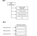
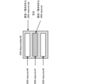
- FIG. 6B is a conceptual diagram of SRS resources and SRS resource sets.
- FIG. 7 is a diagram showing an overview of option 1 of the first embodiment.
- FIG. 8 is a diagram showing an example of RRC parameters NZP-CSI-RS-Resource and NZP-CSI-RS-ResourceSet in option 1-1 of the first embodiment.
- FIG. 9 is a diagram showing an example of MAC CE of option 1-2 of the first embodiment.
- FIG. 10 is a diagram showing an overview of option 1 of the second embodiment.
- FIG. 11 is a diagram showing an example of RRC parameters SRS-Resource and SRS-ResourceSet in option 1-1 of the second embodiment.
- FIG. 12 is a diagram showing an example of MAC CE of option 1-2 of the second embodiment.
- FIG. 13 is a diagram illustrating an example of RRC information elements corresponding to the CSI-RS resource set in option 3 of the modification.
- FIG. 14 is a diagram illustrating an example of RRC information elements corresponding to the SRS resource set in option 4 of the modification.
- FIG. 15 is a diagram showing an example of the SRS transmission cycle and the CSI-RS transmission cycle in Embodiment 3-1-1.
- FIG. 19 is a diagram showing an example of option 1 of embodiment 3-1-2.
- FIG. 20 is a diagram showing examples of options 2 and 3 of embodiment 3-1-2.
- FIG. 21 is a diagram illustrating an example of antenna ports of a UE.
- FIG. 22 is a diagram showing an example of an antenna port pattern in Embodiment 3-2-1.
- FIG. 23 is a diagram showing an example of an antenna port pattern in Embodiment 3-2-2.
- FIG. 24 is a diagram illustrating an example of a schematic configuration of a wireless communication system according to an embodiment.
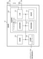
- FIG. 25 is a diagram illustrating an example of the configuration of a base station according to an embodiment.
- FIG. 26 is a diagram illustrating an example of the configuration of a user terminal according to an embodiment.
- FIG. 27 is a diagram illustrating an example of the hardware configuration of a base station and a user terminal according to an embodiment.
- FIG. 28 is a diagram illustrating an example of a vehicle according to an embodiment.
- AI Artificial Intelligence
- ML machine learning
- improved Channel State Information Reference Signal e.g., reduced overhead, improved accuracy, prediction
- improved beam management e.g., improved accuracy, time
- positioning e.g., position estimation/prediction in the spatial domain
- position measurement e.g., position estimation/prediction
- FIG. 1 is a diagram illustrating an example of an AI model management framework.
- each stage related to the AI model is shown as a block.
- This example is also expressed as AI model life cycle management.
- the data collection stage corresponds to the stage of collecting data for generating/updating an AI model.
- the data collection stage includes data reduction (e.g., deciding which data to transfer for model training/model inference), data transfer (e.g., to entities performing model training/model inference (e.g., UE, gNB)), and transfer data).
- model training is performed based on the data (training data) transferred from the collection stage.
- This stage includes data preparation (e.g., performing data preprocessing, cleaning, formatting, transformation, etc.), model training/validation, and model testing (e.g., ensuring that the trained model meets performance thresholds).
- model exchange e.g., transferring a model for distributed learning
- model deployment/updating deploying/updating a model to entities performing model inference
- model inference is performed based on the data (inference data) transferred from the collection stage.
- This stage includes data preparation (e.g., performing data preprocessing, cleaning, formatting, transformation, etc.), model inference, model monitoring (e.g., monitoring the performance of model inference), and model performance feedback (the entity performing model training). (feedback of model performance to actors), output (provide model output to actors), etc.
- the Actor stage provides information necessary for action triggers (e.g., deciding whether to trigger an action on other entities), feedback (e.g., training data/inference data/performance feedback). (feedback) etc.
- action triggers e.g., deciding whether to trigger an action on other entities
- feedback e.g., training data/inference data/performance feedback. (feedback) etc.
- training of a model for mobility optimization may be performed, for example, in Operation, Administration and Maintenance (Management) (OAM) in a network (Network (NW)) / gNodeB (gNB).
- OAM Operation, Administration and Maintenance
- NW Network
- gNodeB gNodeB
- the former has advantages in interoperability, large storage capacity, operator manageability, and model flexibility (e.g., feature engineering). In the latter case, the advantage is that there is no need for model update latency or data exchange for model development.
- Inference of the above model may be performed in the gNB, for example.
- the entity that performs training/inference may be different.
- the OAM/gNB may perform model training and the gNB may perform model inference.
- a Location Management Function may perform model training, and the LMF may perform model inference.
- the OAM/gNB/UE may perform model training and the gNB/UE (jointly) may perform model inference.
- the OAM/gNB/UE may perform model training and the UE may perform model inference.
- Identifier (ID)-based model approaches can be one way to manage AI models in such scenarios.
- the NW/gNB does not know the details of the AI model, but may only know some information about the AI model (for example, which ML model is used for what purpose in the UE) for AI model management. I can do it.
- FIG. 2 is a diagram showing an example of specifying an AI model.
- the UE and NW eg, base station (BS)
- NW eg, base station (BS)
- the UE may report, for example, the performance of model #1 and the performance of model #2 to the NW, and the NW may instruct the UE about the AI model to use.
- the UE/BS inputs channel state information, reference signal measurements, etc. to the ML model to obtain highly accurate channel state information/measurements/beam selection/position, future channel state information, etc. /Wireless link quality, etc. may be output.
- AI may be read as an object (also referred to as a target, object, data, function, program, etc.) that has (implements) at least one of the following characteristics: ⁇ Estimation based on observed or collected information; - Selection based on observed or collected information; - Predictions based on observed or collected information.
- an object may be, for example, an apparatus, a device, such as a terminal or a base station. Furthermore, in the present disclosure, an object may correspond to a program/model/entity that operates on the device.
- the ML model may be replaced by an object that has (implements) at least one of the following characteristics: ⁇ Produce estimates by feeding information, ⁇ Predict the estimated value by giving information, ⁇ Discover characteristics by providing information, ⁇ Select an action by providing information.
- ML model, model, AI model, predictive analytics, predictive analysis model, etc. may be read interchangeably.
- the ML model may be derived using at least one of regression analysis (eg, linear regression analysis, multiple regression analysis, logistic regression analysis), support vector machine, random forest, neural network, deep learning, and the like.
- regression analysis eg, linear regression analysis, multiple regression analysis, logistic regression analysis
- support vector machine random forest, neural network, deep learning, and the like.
- a model may be interpreted as at least one of an encoder, a decoder, a tool, etc.
- the ML model Based on the input information, the ML model outputs at least one information such as an estimated value, a predicted value, a selected action, a classification, etc.
- the ML model may include supervised learning, unsupervised learning, reinforcement learning, and the like.
- Supervised learning may be used to learn general rules that map inputs to outputs.
- Unsupervised learning may be used to learn features of the data.
- Reinforcement learning may be used to learn actions to maximize a goal.
- generation, calculation, derivation, etc. may be read interchangeably.
- implementation, operation, operation, execution, etc. may be read interchangeably.
- training, learning, updating, retraining, etc. may be used interchangeably.
- inference, after-training, production use, actual use, etc. may be read interchangeably.
- Signal may be interchanged with signal/channel.
- a terminal also referred to as a user terminal, User Equipment (UE), etc. transmits channel state information (CSI) based on a reference signal (RS) (or resources for the RS). )) (also referred to as determination, calculation, estimation, measurement, etc.) and transmits (also referred to as report, feedback, etc.) the generated CSI to the network (for example, a base station).
- the CSI may be transmitted to the base station using, for example, an uplink control channel (eg, Physical Uplink Control Channel (PUCCH)) or an uplink shared channel (eg, Physical Uplink Shared Channel (PUSCH)).
- PUCCH Physical Uplink Control Channel
- PUSCH Physical Uplink Shared Channel
- the RS used to generate CSI is, for example, a channel state information reference signal (CSI-RS), a synchronization signal/physical broadcast channel (SS/PBCH) block, or a synchronization signal/physical broadcast channel (SS/PBCH) block.
- CSI-RS channel state information reference signal
- SS/PBCH synchronization signal/physical broadcast channel
- SS/PBCH synchronization signal/physical broadcast channel
- DMRS demodulation reference signal
- the CSI-RS may include at least one of a Non-Zero Power (NZP) CSI-RS and a CSI-Interference Management (CSI-IM).
- the SS/PBCH block is a block that includes SS and PBCH (and corresponding DMRS), and may be called an SS block (SSB) or the like. Further, the SS may include at least one of a primary synchronization signal (PSS) and a secondary synchronization signal (SSS).
- PSS primary synchronization signal
- SSS secondary synchronization signal
- CSI includes a channel quality indicator (CQI), a precoding matrix indicator (PMI), a CSI-RS resource indicator (CRI), and a SS /PBCH block resource indicator (SSBRI), layer indicator (LI), rank indicator (RI), L1-RSRP (reference signal reception in layer 1) Power (Layer 1 Reference Signal Received Power)), L1-RSRQ (Reference Signal Received Quality), L1-SINR (Signal to Interference plus Noise Ratio), L1-SNR (Signal to Noise Ratio), etc. even if it contains at least one of good.
- CQI channel quality indicator
- PMI precoding matrix indicator
- CRI CSI-RS resource indicator
- SSBRI SS /PBCH block resource indicator
- L1-RSRP reference signal reception in layer 1 Power (Layer 1 Reference Signal Received Power)
- L1-RSRQ Reference Signal Received Quality
- L1-SINR Signal Received Quality
- L1-SNR Synignal to Noise Ratio
- the UE may receive information regarding CSI reporting (report configuration information) and control CSI reporting based on the report configuration information.
- the report configuration information may be, for example, "CSI-ReportConfig" of an information element (IE) of radio resource control (RRC).
- IE information element
- RRC radio resource control
- the report configuration information may include, for example, at least one of the following.
- - Information about the type of CSI report (report type information, e.g. "reportConfigType” of RRC IE)
- - Information regarding one or more quantities of CSI to be reported (one or more CSI parameters)
- report quantity information e.g. "reportQuantity” of RRC IE
- report quantity information e.g. "reportQuantity” of RRC IE
- resource information for example, "CSI-ResourceConfigId" of the RRC IE
- frequency domain information e.g. "reportFreqConfiguration" of RRC IE
- the report type information may include periodic CSI (P-CSI) reporting, aperiodic CSI (A-CSI) reporting, or semi-persistent (semi-persistent, semi-persistent) reporting.
- P-CSI periodic CSI
- A-CSI aperiodic CSI
- SP-CSI Semi-Persistent CSI
- the report amount information may specify at least one combination of the above CSI parameters (for example, CRI, RI, PMI, CQI, LI, L1-RSRP, etc.).
- the resource information may be an ID of an RS resource.
- the RS resources may include, for example, non-zero power CSI-RS resources or SSBs and CSI-IM resources (for example, zero-power CSI-RS resources).
- the frequency domain information may also indicate the frequency granularity of the CSI report.
- the frequency granularity may include, for example, widebands and subbands.
- Wideband is the entire CSI reporting band.
- the wideband may be, for example, the entirety of a certain carrier (component carrier (CC), cell, serving cell), or the entire bandwidth part (BWP) within a certain carrier. There may be.
- the wideband may also be referred to as a CSI reporting band, the entire CSI reporting band, or the like.
- a subband is a part of a wideband, and may be composed of one or more resource blocks (Resource Block (RB) or Physical Resource Block (PRB)).
- the size of the subband may be determined according to the size of the BWP (number of PRBs).
- the frequency domain information may indicate whether wideband or subband PMI is to be reported (the frequency domain information may include, for example, the RRC IE used to determine whether to report wideband or subband PMI). (may include "pmi-FormatIndicator").
- the UE may determine the frequency granularity of the CSI report (ie, either wideband PMI report or subband PMI report) based on at least one of the report amount information and frequency domain information.
- wideband PMI reporting is configured (determined)
- one wideband PMI may be reported for the entire CSI reporting band.
- subband PMI reporting is configured, a single wideband indication i1 is reported for the entire CSI reporting band, and a subband indication for each of one or more subbands within the entire CSI reporting band. (one subband indication) i2 (eg, subband indication of each subband) may be reported.
- the UE performs channel estimation using the received RS and estimates a channel matrix H.
- the UE feeds back an index (PMI) that is determined based on the estimated channel matrix.
- the PMI may indicate a precoder matrix (also simply referred to as a precoder) that the UE considers appropriate for use in downlink (DL) transmission to the UE.
- a precoder matrix also simply referred to as a precoder
- Each value of PMI may correspond to one precoder matrix.
- a set of PMI values may correspond to a different set of precoder matrices, referred to as a precoder codebook (also simply referred to as a codebook).
- a CSI report may include one or more types of CSI.
- the CSI may include at least one of a first type (type 1 CSI) used for single beam selection and a second type (type 2 CSI) used for multi beam selection.
- a single beam may be expressed as a single layer, and a multibeam may be expressed as a plurality of beams.
- type 1 CSI does not assume multi-user multiple input multiple output (MIMO), and type 2 CSI may assume multi-user MIMO.
- the codebook may include a codebook for type 1 CSI (also referred to as type 1 codebook, etc.) and a codebook for type 2 CSI (also referred to as type 2 codebook, etc.). Further, type 1 CSI may include type 1 single panel CSI and type 1 multi-panel CSI, and different codebooks (type 1 single panel codebook, type 1 multi-panel codebook) may be defined for each.
- Type 1 and Type I may be read interchangeably.
- Type 2 and Type II may be interchanged.
- the uplink control information (UCI) type may include at least one of Hybrid Automatic Repeat Request ACKnowledgement (HARQ-ACK), scheduling request (SR), and CSI.
- UCI may be carried by PUCCH or PUSCH.
- the UCI may include one CSI part for wideband PMI feedback.
- CSI report #n includes PMI wideband information if reported.
- the UCI may include two CSI parts for subband PMI feedback.
- CSI part 1 includes wideband PMI information.
- CSI part 2 includes one wideband PMI information and some subband PMI information.
- CSI part 1 and CSI part 2 are encoded separately.
- FIG. 3 shows Rel. 15/16 is a diagram showing CSI report configuration (CSI-ReportConfig) of NR.
- the UE is configured by an upper layer with a report setting of N (N ⁇ 1) CSI report settings and a resource setting of M (M ⁇ 1) CSI resource settings.
- the CSI report configuration includes channel measurement resource settings (resourcesForChannelMeasurement), interference CSI-IM resource settings (csi-IM-ResourceForInterference), and interference NZP-CSI-RS settings (nzp-CSI-RS -ResourceForInterference), report quantity (reportQuantity), report type (periodic(p)/semipersistent(sp)/periodic(a))), codebook settings (CodebookConfig), etc.
- Each of the channel measurement resource setting, interference CSI-IM resource setting, and interference NZP-CSI-RS setting is associated with a CSI resource configuration (CSI-ResourceConfig, CSI-ResourceConfigId).
- the CSI resource configuration includes a list of CSI-RS resource sets (CSI-RS-ResourceSetList, eg, NZP-CSI-RS resource set or CSI-IM resource set).
- FIG. 4 is a diagram showing the relationship between the reporting setting (CSI reporting Setting) corresponding to the CSI reporting setting (CSI-ReportConfig) and the resource setting (Resource setting) of the CSI resource setting.
- the resource settings include multiple CSI-RS resource sets.
- the CSI-RS resource set includes a plurality of CSI-RS resources.
- a resource setting is associated with one or more reporting settings.
- SRS Signal Reference Signals
- NR SRS is used not only for uplink (UL) CSI measurement, which is also used in existing LTE (LTE Rel. 8-14), but also for downlink (DL) CSI measurement, beam It is also used for beam management, etc.
- the UE may be configured with one or more SRS resources.
- SRS resources may be identified by an SRS Resource Index (SRI).
- SRI SRS Resource Index
- Each SRS resource may have one or more SRS ports (may correspond to one or more SRS ports).
- the number of ports for each SRS may be 1, 2, 4, etc.
- the UE may be configured with one or more SRS resource sets.
- One SRS resource set may be associated with a predetermined number of SRS resources.
- the UE may use upper layer parameters in common with respect to SRS resources included in one SRS resource set.
- the resource set in the present disclosure may be read as a set, resource group, group, or the like.
- Information regarding SRS resources or resource sets may be configured in the UE using upper layer signaling, physical layer signaling, or a combination thereof.
- the SRS configuration information element (for example, the RRC information element "SRS-Config") may include an SRS resource set configuration information element, an SRS resource configuration information element, etc.
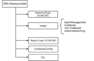
- FIG. 5 shows Rel. 15/16 is a diagram showing the SRS resource set configuration information element (RRC parameter "SRS-ResourceSet”) of NR.
- the SRS resource set configuration information element may include information on the SRS resource type (resourceType), SRS usage (usage), report type (Report type), codebook configuration (CodebookConfig), and the like.
- the SRS resource set configuration information element may further include an SRS resource set ID (Identifier) (SRS-ResourceSetId), a list of SRS resource IDs (SRS-ResourceId) used in the resource set, and the like.
- the SRS resource type may indicate the time domain behavior of SRS resource configuration, such as Periodic SRS (P-SRS), Semi-Persistent SRS ( SP-SRS) or aperiodic SRS (A-SRS).
- P-SRS Periodic SRS
- SP-SRS Semi-Persistent SRS
- A-SRS aperiodic SRS
- the UE may transmit the P-SRS and SP-SRS periodically (or periodically after activation).
- the UE may transmit the A-SRS based on the DCI's SRS request.
- SRS RRC parameter "usage", L1 (Layer-1) parameter "SRS-SetUse”
- L1 (Layer-1) parameter "SRS-SetUse” is, for example, beam management (beamManagement), codebook (CB), non-codebook (CB), non-codebook (NCB)), antenna switching (antenna switching), etc.
- the SRS for codebook or non-codebook use may be used to determine a precoder for SRI-based codebook-based or non-codebook-based Physical Uplink Shared Channel (PUSCH) transmission.
- PUSCH Physical Uplink Shared Channel
- SRS for beam management purposes may assume that only one SRS resource for each SRS resource set can be transmitted at a given time instant. Note that in the same Bandwidth Part (BWP), if a plurality of SRS resources corresponding to the same time domain behavior belong to different SRS resource sets, these SRS resources may be transmitted simultaneously.
- BWP Bandwidth Part
- the SRS resource configuration information element (for example, "SRS-Resource” of the RRC parameter) includes the resource type (resourceType), the SRS resource ID (SRS-ResourceId), the number of transmission combs, etc. (FIG. 6A).
- the resource type is similar to the resource type in the SRS resource set configuration described above, and may indicate periodic SRS, semi-persistent SRS, or aperiodic SRS.
- the SRS resource configuration information elements further include the number of SRS ports, the SRS port number, the SRS resource mapping (e.g., time and/or frequency resource location, resource offset, period of the resource, number of repetitions, number of SRS symbols, SRS bandwidth, etc.) , hopping related information, SRS resource type, sequence ID, spatial relationship information, etc.
- One or more SRS resources may be included in an SRS resource set (FIG. 6B).
- channel reciprocity can be used to obtain DL CSI from UL reference signals.
- channel characteristics/frequency bands are different between DL and UL, so channel reciprocity cannot be fully utilized like in TDD systems, so DL CSI is obtained from the PMI report generated by the UE after CSI estimation. are doing.
- the base station can infer the DL CSI of the DL frequency band from the UL CSI of the UL frequency band adjacent to the DL frequency band using an AI/ML model. Since gNB can obtain UL CSI from UL SRS, it can solve the problem of CSI feedback payload and incomplete CSI estimation on the UE side.
- the data sets of UL CSI/RS for example, SRS
- DL CSI which is the output of the model
- SRS UL CSI/RS
- DL CSI which is the output of the model
- DL CSI and UL CSI/RS preferably have a consistent time difference within the data set.
- the transmission and reception ports of DL CSI and UL CSI/RS match within the data set.
- the present inventors came up with a method for the UE to transmit an appropriate UL signal corresponding to a DL signal.
- A/B and “at least one of A and B” may be read interchangeably. Furthermore, in the present disclosure, “A/B/C” may mean “at least one of A, B, and C.”
- Radio Resource Control RRC
- RRC parameters RRC parameters
- RRC messages upper layer parameters, fields, Information Elements (IEs), settings, etc.
- IEs Information Elements
- CE Medium Access Control Element
- update command activation/deactivation command, etc.
- the upper layer signaling may be, for example, Radio Resource Control (RRC) signaling, Medium Access Control (MAC) signaling, broadcast information, etc., or a combination thereof.
- RRC Radio Resource Control
- MAC Medium Access Control
- MAC signaling may use, for example, a MAC Control Element (MAC CE), a MAC Protocol Data Unit (PDU), or the like.
- Broadcast information includes, for example, a master information block (MIB), a system information block (SIB), a minimum system information (RMSI), and other system information ( Other System Information (OSI)) may also be used.
- MIB master information block
- SIB system information block
- RMSI minimum system information
- OSI Other System Information
- the physical layer signaling may be, for example, downlink control information (DCI), uplink control information (UCI), etc.
- DCI downlink control information
- UCI uplink control information
- an index an identifier (ID), an indicator, a resource ID, etc.
- ID an identifier
- indicator an indicator
- resource ID a resource ID
- sequences, lists, sets, groups, groups, clusters, subsets, etc. may be used interchangeably.
- the settings/instructions may be read as activation or activation settings/instructions.
- RRC/MAC CE/DCI may be replaced with at least one of the above upper layer signaling/physical layer signaling.
- CSI-RS and CSI may be read interchangeably.
- SRS resource set and “SRS resource” in this disclosure may be interchanged.
- the CSI-RS resource set and CSI-RS resource in this disclosure may be read interchangeably. Adjustment, determination, selection, setting, and control in the present disclosure may be read interchangeably.
- the UE configures/instructs one or more CSI-RS resources or one or more CSI-RS resource sets (first configuration/indication) from the base station (gNB) (option 1). Alternatively, the UE selects/determines one or more CSI-RS resources or one or more CSI-RS resource sets for coordination between DL and UL, and uses UL signals (e.g. PUCCH/PUSCH) to communicate with the base station. (gNB) (option 2). The UE controls (adjusts) at least one of the period, offset, and antenna port between DL and UL based on the settings/instructions. This control will be explained in the third embodiment below.
- the UE identifies one or more non-zero power CSI-RS resource set IDs (NZP-CSI-RS- ResourceSetId) settings/instructions may be received.
- the UE configures/sets a non-zero power CSI-RS resource ID (NZP-CSI-RS-ResourceId) corresponding to one or more CSI-RS resources for coordination between DL and UL using RRC/MAC CE/DCI, etc. Instructions may be received.
- the settings/instructions by the RRC will be explained in detail in option 1-1
- the settings/instructions by the MAC CE will be explained in option 1-2
- the settings/instructions by the MAC CE will be explained in detail in option 1-3.
- FIG. 7 is a diagram showing an overview of option 1 of the first embodiment.
- the UE configures/instructs at least one CSI-RS resource set or CSI-RS resource from among the multiple CSI-RS resource sets or CSI-RS resources, for example, by RRC/MAC CE/DCI, etc. receive.
- the UE may receive information indicating coordination between DL and UL through RRC signaling (RRC configuration). For example, at least one of the RRC parameter corresponding to the CSI-RS resource (NZP-CSI-RS-Resource) and the RRC parameter corresponding to the CSI-RS resource set (NZP-CSI-RS-ResourceSet) is set between the DL and the UL. It may also include information indicating adjustment (DL-UL-alignment).
- RRC configuration For example, at least one of the RRC parameter corresponding to the CSI-RS resource (NZP-CSI-RS-Resource) and the RRC parameter corresponding to the CSI-RS resource set (NZP-CSI-RS-ResourceSet) is set between the DL and the UL. It may also include information indicating adjustment (DL-UL-alignment).
- FIG. 8 is a diagram showing an example of RRC parameters NZP-CSI-RS-Resource and NZP-CSI-RS-ResourceSet in option 1-1 of the first embodiment.
- the new NZP-CSI-RS-Resource and NZP-CSI-RS-ResourceSet include information indicating alignment between DL and UL (DL-UL-alignment). For example, setting DL-UL-alignment to 0 means that the adjustment between DL and UL is invalid (or valid) for the corresponding NZP-CSI-RS-Resource/NZP-CSI-RS-ResourceSet.
- Setting DL-UL-alignment to 1 means that the adjustment between DL and UL is valid (or invalid) for the corresponding NZP-CSI-RS-Resource/NZP-CSI-RS-ResourceSet. May be shown.
- FIG. 9 is a diagram showing an example of MAC CE of option 1-2 of the first embodiment.
- the A/D field indicates whether to activate or deactivate the alignment between DL and UL (DL-UL alignment). This field is set to 1 (or 0) if the adjustment is activated (adjustment is made), and 0 (or 1) otherwise. Other fields (for example, any R field) may be used as the field indicating whether to activate or deactivate the adjustment.
- the Serving Cell ID field indicates the serving cell ID to which the MAC CE is applied.
- the length of this field is, for example, 5 bits.
- the BWP ID field indicates the DL BWP to which the MAC CE is applied, as a code point of the BWP indication (bandwidth part indicator) field of the DCI.
- the length of the BWP ID field is, for example, 2 bits.
- the NZP CSI-RS Resource Set ID field contains the index of the NZP-CSI-RS-ResourceSet containing the NZP CSI-RS resources, and the CSI-RS containing one or more CSI-RS resources for which coordination between DL and UL is activated. Indicates an RS resource set.
- the IM field indicates the presence of a CSI-RS resource set ID field included in the same octet. If the IM field is set to 1, there is a CSI-RS Resource Set ID field included in the octet. Otherwise, the CSI-RS resource set ID field does not exist.
- the CSI-RS resource ID field stores an index of nzp-CSI-RS-ResourceId indicating a CSI-RS resource that is activated for coordination between DL and UL. R is a reserved bit and is set to 0.
- the UE receives settings/instructions corresponding to one or more CSI-RS resources or one or more CSI-RS resource sets for DL and UL alignment (DL-UL alignment) from the base station (gNB) using the DCI. You may receive it.
- DL-UL alignment DL-UL alignment
- the UE receives an instruction for coordination between the DL and UL in which reserved bits of the DCI are used, and, in accordance with the instruction, identifies the ID of the CSI-RS resource or the CSI-RS resource for which coordination between the DL and the UL is activated.
- the ID of the set may be received using the PDSCH.
- the UE receives an indication of coordination between the DL and UL using the already existing DCI field (e.g. in Rel. 15/16), and in response to the indication, the CSI- The RS resource ID or the CSI-RS resource set ID may be transmitted using the PDSCH.
- the already existing DCI field e.g. in Rel. 15/16
- the UE receives an indication of DL-to-UL coordination using a specific type of Radio Network Temporary Identifier (RNTI) in the DCI, and in response to the instruction, the CSI-RS in which the DL-to-UL coordination is activated.
- RNTI Radio Network Temporary Identifier
- the resource ID or the CSI-RS resource set ID may be transmitted using the PDSCH.
- the UE selects/determines one or more CSI-RS resources for coordination between DL and UL (without configuration/indication from the base station), and identifies the corresponding one or more CSI-RS resources ID ( NZP-CSI-RS-ResourceId) may be transmitted (feedback) to the base station (gNB) in a UL signal (for example, PUCCH/PUSCH).
- the UE selects/determines one or more CSI-RS resource sets (without using configuration/instructions from the base station), and assigns IDs (NZP-CSI-RS-ResourceSetId) of the corresponding one or more CSI-RS resource sets. ) may be transmitted (feedback) to the base station (gNB) in a UL signal (for example, PUCCH/PUSCH).
- the NZP-CSI-RS-ResourceSetId sent by the UE indicates one of the NZP-CSI-RS-ResourceSets included in the list (nzp-CSI-RS-ResourceSetToAddModList) set by the base station through upper layer signaling (RRC), etc. May be shown.
- the NZP-CSI-RS-ResourceId sent by the UE indicates one of the NZP-CSI-RS-Resources included in the list (nzp-CSI-RS-ResourceToAddModList) set by the base station through upper layer signaling (RRC), etc. May be shown.
- the CSI-RS resource or CSI-RS resource set used for coordination between DL and UL becomes clear, so the UE can appropriately perform coordination between DL and UL.
- the UE configures/instructs (second configuration/instructions) one or more SRS resources or one or more SRS resource sets for coordination between DL and UL (DL-UL alignment) using RRC/MAC CE/DCI, etc. ) may be received from the base station (gNB) (option 1). Alternatively, the UE selects/determines one or more CSI-RS resources or one or more CSI-RS resource sets for coordination between DL and UL, and uses UL signals (e.g. PUCCH/PUSCH) to communicate with the base station. (gNB) (option 2). The UE controls at least one of the period, offset, and antenna port between DL and UL based on the settings/instructions. This control will be explained in the third embodiment below.
- the UE uses the SRS-ResourceSetId of the SRS resource set for coordination between the DL and UL configured from the base station (gNB), and the DL and UL configured from the base station (gNB) by RRC/MAC CE/DCI etc. may receive the srs-ResourceId of the SRS resource for coordination between.
- FIG. 10 is a diagram showing an overview of option 1 of the second embodiment.
- the UE configures/instructs coordination between DL and UL for at least one SRS resource set or SRS resource among multiple SRS resource sets or multiple SRS resources, for example, by RRC/MAC CE/DCI, etc. Activation settings/instructions).
- the UE may receive information indicating coordination between DL and UL through higher layer signaling (RRC signaling, RRC configuration).
- RRC signaling RRC signaling, RRC configuration
- at least one of the RRC parameters SRS-Resource and SRS-ResourceSet may include information indicating alignment between DL and UL (DL-UL-alignment).
- FIG. 11 is a diagram showing an example of RRC parameters SRS-Resource and SRS-ResourceSet in option 1-1 of the second embodiment.
- the new SRS-Resource and SRS-ResourceSet include information indicating alignment between DL and UL (DL-UL-alignment). For example, DL-UL-alignment being set to 0 may indicate that coordination between DL and UL is invalid (or valid) for the corresponding SRS-Resource/SRS-ResourceSet. Setting DL-UL-alignment to 1 may indicate that adjustment between DL and UL is valid (or invalid) for the corresponding SRS-Resource/SRS-ResourceSet.
- the UE may receive settings/instructions (activation settings/instructions) corresponding to SRS resources or SRS resource sets for coordination between DL and UL from the base station (gNB) using the MAC CE.
- Some bits of the MAC CE are used to indicate settings/instructions for coordination between DL and UL, and other bits are used to indicate the corresponding active one or more SRS resources or one or more SRS resource sets. ID may be shown.
- FIG. 12 is a diagram showing an example of MAC CE of option 1-2 of the second embodiment.
- the A/D field indicates whether to activate or deactivate the alignment between DL and UL (DL-UL alignment). This field is set to 1 (or 0) if the adjustment is activated (adjustment is made), and 0 (or 1) otherwise. Other fields (for example, any R field) may be used as the field indicating whether to activate or deactivate the adjustment.
- the Serving Cell ID field indicates the serving cell ID to which the MAC CE is applied.
- the length of this field is, for example, 5 bits.
- the BWP ID field indicates the DL BWP to which the MAC CE is applied, as a code point of the BWP indication (bandwidth part indicator) field of the DCI.
- the length of the BWP ID field is, for example, 2 bits.
- the SRS resource set ID field contains an index of an SRS-ResourceSet containing SRS resources, and indicates an SRS resource set containing one or more SRS resources for which coordination between DL and UL is activated.
- the IM field indicates the presence of the SRS Resource Set ID field included in the same octet. If the IM field is set to 1, there is an SRS Resource Set ID field included in the octet. Otherwise, the SRS resource set ID field does not exist.
- the SRS Resource ID field stores an index of srs-ResourceId indicating the SRS resource for which coordination between DL and UL is activated. R is a reserved bit and is set to 0.
- the UE may receive settings/instructions corresponding to SRS resources or SRS resource sets for DL-UL alignment from the base station (gNB) using the DCI.
- the UE receives an indication of coordination between the DL and UL in which reserved bits of the DCI are used, and in response to the instruction, determines the ID of the SRS resource or the ID of the SRS resource set for which coordination between the DL and the UL is activated.
- PDSCH may be used for reception.
- the UE receives an indication of coordination between DL and UL using the already existing (e.g. in Rel. or the ID of the SRS resource set may be received using the PDSCH.
- the UE receives an indication of DL-to-UL coordination using a specific type of RNTI in the DCI, and depending on the instruction, the ID of the SRS resource or the SRS resource set for which the DL-to-UL coordination is activated.
- the ID may be received using the PDSCH.
- the UE selects/determines one or more SRS resources for coordination between DL and UL, and sends the corresponding one or more SRS resource IDs (srs-ResourceId) to the base station (gNB) in the UL signal (e.g. PUCCH/PUSCH). ) may be sent (feedback).
- the UE selects/determines one or more SRS resource sets for coordination between DL and UL, and transmits the corresponding one or more SRS resource set IDs (SRS-ResourceSetId) to the base station in the UL signal (e.g. PUCCH/PUSCH). It may also be transmitted (feedback) to (gNB).
- the SRS-ResourceSetId transmitted by the UE may indicate any of the SRS-ResourceSets included in the list (SRS-ResourceSetToAddModList) set by the base station through upper layer signaling (RRC) or the like.
- the srs-ResourceId transmitted by the UE may indicate any of the SRS-Resources included in the list (SRS-ResourceToAddModList) set by the base station through upper layer signaling (RRC) or the like.
- the SRS resource or SRS resource set used for adjustment between DL and UL becomes clear, so the UE can appropriately perform adjustment between DL and UL.
- ⁇ Modified example> A modified example of the method of setting/instructing SRS and CSI-RS for DL-UL alignment (DL-UL alignment) described in the first embodiment and second embodiment will be described.
- the specific SRS resource set may be, for example, an SRS resource set whose usage is antenna switching. This is because an SRS resource set whose purpose is antenna switching is used for DL CSI estimation.
- TRS tracking reference signal
- the UE changes the SRS transmission timing based on the TRS. This is because periodic CSI-RSs, especially TRSs, are shared by most UEs, so it is preferable not to dynamically and frequently change TRS resource mapping for coordination between DL and UL.
- the specific CSI-RS resource set may be a CSI-RS resource set that includes associated CSI-RSs within the SRS resource set.
- the UE shall It may be determined that coordination between DL and UL has been set/instructed for the set and the corresponding SRS resource set (FIG. 13).
- the UE sets a CSI-RS resource set ID (nzp-CSI-ResourceSetId) for coordination between DL and UL in the RRC information element (SRS-ResourceSet in SRS-Config) corresponding to the SRS resource set.
- nzp-CSI-ResourceSetId the RRC information element
- SRS-ResourceSet in SRS-Config the RRC information element
- the SRS resource set/CSI-RS resource set for coordination between DL and UL configured in options 1 to 4 may be mapped (activated/instructed) by MAC CE/DCI.
- the SRS resource set in the modified example may be read as SRS resource.
- the CSI-RS resource set in the modified example may be replaced with CSI-RS resource.
- the UE configures/instructs one or more CSI-RS resources or one or more CSI-RS resource sets for coordination between DL and UL (DL-UL alignment) (first embodiment), or configures/instructs DL and UL alignment. If the configuration/instruction (second embodiment) of one or more SRS resources or SRS resource sets for DL-UL alignment is not received, it may be determined not to transmit the CSI report. In this case, it is considered that the base station has been able to estimate the DL CSI with sufficiently high accuracy, so it is considered that the setting/instruction was not made.
- the UE may decide not to transmit the CSI report when receiving the above settings/instructions (first embodiment/second embodiment). This is because the UE can estimate the DC CSI from the UL CSI (SRS) with high accuracy at the base station by performing the adjustment described below (in the third embodiment).
- SRS UL CSI
- the settings/instructions include settings/instructions for one or more CSI-RS resources or one or more CSI-RS resource sets for coordination between DL and UL in the first embodiment, and settings/instructions for one or more CSI-RS resource sets in the second embodiment. It may be at least one of the settings/instructions of one or more SRS resources or SRS resource sets for coordination between DL and UL, or it may be other settings/instructions.
- the UE determines the period/offset of the SRS resource or SRS resource set (for example, the SRS resource/SRS resource set configured/instructed or selected by the method of the second embodiment) for coordination between the DL and the UL. and the period of the CSI-RS resource or CSI-RS resource set (for example, the CSI-RS resource/CSI-RS resource set configured/instructed or selected by the method of the first embodiment) for coordination between the UL and the UL. Adjust based on offset.
- the UE receives an adjustment instruction between DL and UL through, for example, RRC/MAC CE/DCI, and adjusts the period/offset of the SRS resource/SRS resource set based on the instruction.
- the UE controls the SRS transmission timing to be the same as the CSI-RS reception timing, but it does not have to be completely the same; for example, the UE controls the SRS transmission timing to be the same as the CSI-RS reception timing; May be adjusted.
- the UE may adjust the SRS transmission symbol to a symbol other than the CSI-RS reception symbol and a symbol within the CSI-RS reception slot.
- the UE may adjust the transmitted symbol of the SRS to the symbol in the slot next to the received slot of the CSI-RS.
- the UE may adjust the transmitted symbol of the SRS to be the symbol next to the received symbol of the CSI-RS. This allows interference to be avoided.
- the UE may determine the time difference between the received symbols/slots of the CSI-RS and the transmitted symbols/slots of the SRS based on predetermined rules or settings/instructions via physical layer signaling/upper layer signaling.
- the UE may adjust/determine the offset between the SRS and the CSI-RS based on predetermined rules or settings/instructions via physical layer signaling/upper layer signaling.
- the UE sets the transmission period of the SRS resource/SRS resource set for adjustment between DL and UL at a predetermined ratio to the transmission period of CSI-RS resource or CSI-RS resource set for adjustment between DL and UL. (For example, it may be adjusted to be an integral multiple).
- the value (N) of the predetermined ratio may be defined in the specifications, or may be set/instructed by the base station by RRC/MAC CE/DCI.
- the predetermined ratio value may be selected by the UE and fed back (eg, as UE capabilities) to the base station using the UL signal (eg, UE capabilities).
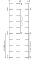
- FIG. 15 is a diagram showing an example of the SRS transmission cycle and the CSI-RS transmission cycle in Embodiment 3-1-1.
- sl18 slot18
- slot20 is set as the CSI transmission cycle.
- the UE selects s140 so that the SRS transmission cycle is a predetermined ratio (for example, 7 times) to the CSI-RS transmission cycle.
- the UE adjusts the offset of the transmission of SRS resources or SRS resource sets for coordination between DL and UL to a new value (eg, a constant value) based on the adjusted period (T srs_new ).
- a new value e.g, a constant value
- T srs_new the offset of transmission of SRS resources or SRS resource sets for adjustment between DL and UL may be simply referred to as offset.
- the UE may determine the offset using a function of the adjusted period (T srs_new ) and the original offset (T offset_old ) of the SRS resource or SRS resource set for coordination between DL and UL.
- the function may be defined in the specification or may be instructed by physical layer signaling/upper layer signaling.
- the UE determines the offset of transmission of the SRS resource or SRS resource set for coordination between DL and UL based on equation (2) below (function of T offset_old and T srs_new ).
- T offset_new T offset_old mod (T srs_new ) (2)
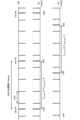
- FIG. 19 is a diagram showing an example of option 1 of embodiment 3-1-2.
- the period before SRS update (T srs_old ) is 5
- the offset before SRS update (T offset_old ) is 4
- the period after SRS update (T srs_new ) is 4. do.
- the SRS cycle is updated, for example, by the method of Embodiment 3-1-1.
- the UE determines the updated offset (T offset_new ) of the SRS to be 0 based on the above equation (2), and transmits the SRS using the new period (T srs_new ) and the new offset (T offset_new ).
- the UE may determine the offset based on a value defined in the specifications, or may set it by RRC/MAC CE/DCI.
- the offset may be from 0 to T srs_new ⁇ 1.
- the UE may select/determine the offset (not set/instructed by the base station) and send it (feedback) to the base station using the UL signal (eg as a UE capability).
- the offset may be from 0 to T srs_new ⁇ 1.
- new1 there is an example (new1) in which the period after SRS update (T srs_new ) is 4 and the offset after SRS update (T offset_new ) is 0, and the period after SRS update (T srs_new ) is 0. 4 and the offset after SRS update (T offset_new ) is 3 (new2).
- the UE transmits the SRS using a new period (T srs_new ) and a new offset (T offset_new ). However, in the example of new2, the CSI-RS transmission timing and the SRS transmission timing do not match.
- the UE CSI-RS reception/SRS transmission may be performed using UL symbols (slots).
- the valid DL symbol/UL symbol may be a symbol set as DL/UL/flexible by an upper layer signal.
- a valid DL symbol/UL symbol may be a symbol that does not correspond to a symbol for a set measurement gap.
- the SRS can be used to perform DL CSI with high precision. Estimation can be carried out.
- the UE adjusts the DL and UL based on the SRS resource/SRS resource set (for example, the SRS resource/SRS resource set configured/instructed or selected by the method of the second embodiment) for coordination between the DL and the UL.
- the SRS resource/SRS resource set for example, the SRS resource/SRS resource set configured/instructed or selected by the method of the second embodiment
- For DL CSI estimation of CSI-RS resources/CSI-RS resource sets for example, CSI-RS resources/CSI-RS resource sets set/instructed or selected by the method of the first embodiment for coordination between Adjust/select/determine receive antenna port.
- FIG. 21 is a diagram showing an example of the antenna port of the UE. As shown in FIG. 21, the antenna ports (0-3) of the UE are used for transmission and reception. If the use of SRS resources is antenna switching, the antennas may be switched.
- the UE may report UE capability information (for example, RRC parameter "supportedSRS-TxPortSwitch") indicating the SRS transmission port switching pattern that it supports to the network.
- UE capability information for example, RRC parameter "supportedSRS-TxPortSwitch”
- This pattern is expressed in the form of "txry” such as “t1r2", “t2r4", etc., and it means that SRS transmission can be performed using x antenna ports out of a total of y antennas (denoted as xTyR).
- y may correspond to all or a subset of the UE's receive antennas.
- the UE determines a receiving antenna port pattern for DL CSI estimation according to Embodiment 3-2-1 or Embodiment 3-2-2 below.
- the UE may transmit the UE antenna port of Embodiment 3-2-1 and the UE antenna port index of Embodiment 3-2-1 as UE capability information.
- the UE uses the UE antenna port associated with the SRS resource/SRS resource set (SRS-ResourceID/SRS-ResourceSetID) for coordination between DL and UL as the CSI-RS resource/CSI-RS resource for DL CSI estimation. It may be determined to be the antenna port for set reception (FIG. 22).
- a pattern index indicating a pattern of receive antenna ports may be configured in the UE by the base station, or may be selected and reported by the UE. For example, different sets of antenna ports linked for each pattern index may be set from the base station to the UE by RRC/MAC CE/DCI. Alternatively, the UE may select a pattern index to antenna port mapping and use the UL signal to report the receive antenna port corresponding to that value.
- the antenna port corresponding to the antenna port for SRS transmission is used, so DL CSI estimation can be performed with high accuracy.
- the UE may adjust (determine/select) a receiving antenna port for PDSCH/PDCCH reception based on one or more CSI-RS resources or CSI-RS resource sets for coordination between DL and UL. .
- the UE uses the reception antenna port for PDSCH/PDCCH reception as one or more CSI-RS resources or CSI-RS resource set DL CSI estimation for adjustment between DL and UL, which has a QCL relationship with the PDSCH/PDCCH.
- the antenna port may be determined (determined/selected) to be the same as the antenna port (determined in Embodiment 3-2, for example).
- the antenna port corresponding to the antenna port for SRS transmission is used also for PDSCH/PDCCH reception, so it is possible to perform DL CSI estimation with high accuracy.
- ⁇ Supplement> At least one of the embodiments described above may apply only to UEs that have reported or support a particular UE capability.
- the particular UE capability may indicate at least one of the following: - Supporting specific processing/operation/control/information for at least one of the above embodiments. - Support coordination between DL and UL. - Support each embodiment/option's processing/operation/control/information, or a combination thereof.
- the above-mentioned specific UE capability may be a capability that is applied across all frequencies (commonly regardless of frequency), or may be a capability for each frequency (for example, cell, band, BWP). , capability for each frequency range (for example, Frequency Range 1 (FR1), FR2, FR3, FR4, FR5, FR2-1, FR2-2), or for each subcarrier spacing (SCS). It may be the ability of
- the above-mentioned specific UE capability may be a capability that is applied across all duplex schemes (commonly regardless of the duplex scheme), or may be a capability that is applied across all duplex schemes (for example, Time Division Duplex).
- the capability may be for each frequency division duplex (TDD)) or frequency division duplex (FDD)).
- At least one of the embodiments described above may be applied when the UE is configured with specific information related to the embodiment described above by upper layer signaling.
- the UE does not support at least one of the specific UE capabilities or is not configured with the specific information, for example, Rel. 15/16 operations may be applied.
- CSI-RS channel state information reference signal
- SRS measurement reference signal
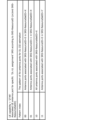
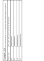
- the terminal according to supplementary note 1 wherein the control unit adjusts a cycle of the measurement reference signal (SRS) resource or the SRS resource set based on a cycle of the CSI-RS resource or the CSI-RS resource set.
- the control unit adjusts the offset of the SRS resource or the SRS resource set based on the adjusted period of the SRS resource or the SRS resource set.
- the control unit determines a receiving antenna port for DL CSI estimation of the CSI-RS resource or the CSI-RS resource set based on the SRS resource or the SRS resource set. The device listed.
- wireless communication system The configuration of a wireless communication system according to an embodiment of the present disclosure will be described below.
- communication is performed using any one of the wireless communication methods according to the above-described embodiments of the present disclosure or a combination thereof.
- FIG. 24 is a diagram illustrating an example of a schematic configuration of a wireless communication system according to an embodiment.
- the wireless communication system 1 may be a system that realizes communication using Long Term Evolution (LTE), 5th generation mobile communication system New Radio (5G NR), etc. specified by the Third Generation Partnership Project (3GPP). .
- LTE Long Term Evolution
- 5G NR 5th generation mobile communication system New Radio
- 3GPP Third Generation Partnership Project
- the wireless communication system 1 (which may be simply referred to as system 1) provides dual connectivity (Multi-RAT Dual Connectivity (MR-DC)) between multiple Radio Access Technologies (RATs). May be supported.
- MR-DC has dual connectivity between LTE (Evolved Universal Terrestrial Radio Access (E-UTRA)) and NR (E-UTRA-NR Dual Connectivity (EN-DC)), and dual connectivity between NR and LTE (NR-E -UTRA Dual Connectivity (NE-DC)).
- LTE Evolved Universal Terrestrial Radio Access
- EN-DC E-UTRA-NR Dual Connectivity
- NE-DC NR-E -UTRA Dual Connectivity
- the LTE (E-UTRA) base station (eNB) is the master node (Master Node (MN)), and the NR base station (gNB) is the secondary node (Secondary Node (SN)).
- the NR base station (gNB) is the MN
- the LTE (E-UTRA) base station (eNB) is the SN.
- the wireless communication system 1 has dual connectivity between multiple base stations within the same RAT (for example, dual connectivity (NR-NR Dual Connectivity (NN-DC) where both the MN and SN are NR base stations (gNB)). )) may be supported.
- dual connectivity NR-NR Dual Connectivity (NN-DC) where both the MN and SN are NR base stations (gNB)).
- the wireless communication system 1 includes a base station 11 that forms a macro cell C1 with relatively wide coverage, and base stations 12 (12a-12c) that are located within the macro cell C1 and form a small cell C2 that is narrower than the macro cell C1. You may prepare.
- User terminal 20 may be located within at least one cell. The arrangement, number, etc. of each cell and user terminal 20 are not limited to the embodiment shown in the figure. Hereinafter, when base stations 11 and 12 are not distinguished, they will be collectively referred to as base station 10.
- the user terminal 20 may be connected to at least one of the plurality of base stations 10.
- the user terminal 20 may use at least one of carrier aggregation (CA) using a plurality of component carriers (CC) and dual connectivity (DC).
- CA carrier aggregation
- CC component carriers
- DC dual connectivity
- Each CC may be included in at least one of a first frequency band (Frequency Range 1 (FR1)) and a second frequency band (Frequency Range 2 (FR2)).
- Macro cell C1 may be included in FR1
- small cell C2 may be included in FR2.
- FR1 may be a frequency band below 6 GHz (sub-6 GHz)
- FR2 may be a frequency band above 24 GHz (above-24 GHz). Note that the frequency bands and definitions of FR1 and FR2 are not limited to these, and FR1 may correspond to a higher frequency band than FR2, for example.
- the user terminal 20 may communicate using at least one of time division duplex (TDD) and frequency division duplex (FDD) in each CC.
- TDD time division duplex
- FDD frequency division duplex
- the plurality of base stations 10 may be connected by wire (for example, optical fiber, X2 interface, etc. compliant with Common Public Radio Interface (CPRI)) or wirelessly (for example, NR communication).
- wire for example, optical fiber, X2 interface, etc. compliant with Common Public Radio Interface (CPRI)
- NR communication for example, when NR communication is used as a backhaul between base stations 11 and 12, base station 11, which is an upper station, is an Integrated Access Backhaul (IAB) donor, and base station 12, which is a relay station, is an IAB donor. May also be called a node.
- IAB Integrated Access Backhaul
- the base station 10 may be connected to the core network 30 via another base station 10 or directly.
- the core network 30 may include, for example, at least one of Evolved Packet Core (EPC), 5G Core Network (5GCN), Next Generation Core (NGC), and the like.
- EPC Evolved Packet Core
- 5GCN 5G Core Network
- NGC Next Generation Core
- the core network 30 includes, for example, User Plane Function (UPF), Access and Mobility Management Function (AMF), Session Management Function (SMF), Unified Data Management (UDM), Application Function (AF), Data Network (DN), and Location Manager.
- UPF User Plane Function
- AMF Access and Mobility Management Function
- SMF Session Management Function
- UDM Unified Data Management
- AF Application Function
- DN Data Network
- NF agement Network Functions
- NF such as Function (LMF) and Operation, Administration and Maintenance (Management) (OAM)
- multiple functions may be provided by one network node.
- communication with an external network eg, the Internet
- the user terminal 20 may be a terminal compatible with at least one of communication systems such as LTE, LTE-A, and 5G.
- an orthogonal frequency division multiplexing (OFDM)-based wireless access method may be used.
- OFDM orthogonal frequency division multiplexing
- CP-OFDM Cyclic Prefix OFDM
- DFT-s-OFDM Discrete Fourier Transform Spread OFDM
- OFDMA Orthogonal Frequency Division Multiple Access
- SC-FDMA Single Carrier Frequency Division Multiple Access
- a wireless access method may also be called a waveform.
- other wireless access methods for example, other single carrier transmission methods, other multicarrier transmission methods
- the UL and DL radio access methods may be used as the UL and DL radio access methods.
- the downlink channels include a physical downlink shared channel (PDSCH) shared by each user terminal 20, a broadcast channel (physical broadcast channel (PBCH)), and a downlink control channel (physical downlink control). Channel (PDCCH)) or the like may be used.
- PDSCH physical downlink shared channel
- PBCH physical broadcast channel
- PDCCH downlink control channel
- uplink channels include a physical uplink shared channel (PUSCH) shared by each user terminal 20, an uplink control channel (PUCCH), and a random access channel. (Physical Random Access Channel (PRACH)) or the like may be used.
- PUSCH physical uplink shared channel
- PUCCH uplink control channel
- PRACH Physical Random Access Channel
- User data, upper layer control information, System Information Block (SIB), etc. are transmitted by the PDSCH.
- User data, upper layer control information, etc. may be transmitted by PUSCH.
- a Master Information Block (MIB) may be transmitted via the PBCH.
- Lower layer control information may be transmitted by PDCCH.
- the lower layer control information may include, for example, downlink control information (DCI) that includes scheduling information for at least one of PDSCH and PUSCH.
- DCI downlink control information
- DCI that schedules PDSCH may be called DL assignment, DL DCI, etc.
- DCI that schedules PUSCH may be called UL grant, UL DCI, etc.
- PDSCH may be replaced with DL data
- PUSCH may be replaced with UL data.
- a control resource set (CONtrol REsource SET (CORESET)) and a search space may be used to detect the PDCCH.
- CORESET corresponds to a resource for searching DCI.
- the search space corresponds to a search area and a search method for PDCCH candidates (PDCCH candidates).
- PDCCH candidates PDCCH candidates
- One CORESET may be associated with one or more search spaces. The UE may monitor the CORESET associated with a certain search space based on the search space configuration.
- One search space may correspond to PDCCH candidates corresponding to one or more aggregation levels.
- One or more search spaces may be referred to as a search space set. Note that “search space”, “search space set”, “search space setting”, “search space set setting”, “CORESET”, “CORESET setting”, etc. in the present disclosure may be read interchangeably.
- the PUCCH allows channel state information (CSI), delivery confirmation information (for example, may be called Hybrid Automatic Repeat Request ACKnowledgement (HARQ-ACK), ACK/NACK, etc.), and scheduling request ( Uplink Control Information (UCI) including at least one of SR)) may be transmitted.
- CSI channel state information
- delivery confirmation information for example, may be called Hybrid Automatic Repeat Request ACKnowledgement (HARQ-ACK), ACK/NACK, etc.
- UCI Uplink Control Information including at least one of SR
- a random access preamble for establishing a connection with a cell may be transmitted by PRACH.
- downlinks, uplinks, etc. may be expressed without adding "link”.
- various channels may be expressed without adding "Physical” at the beginning.
- a synchronization signal (SS), a downlink reference signal (DL-RS), and the like may be transmitted.
- the DL-RS includes a cell-specific reference signal (CRS), a channel state information reference signal (CSI-RS), and a demodulation reference signal (DeModulation).
- Reference Signal (DMRS)), Positioning Reference Signal (PRS), Phase Tracking Reference Signal (PTRS), etc. may be transmitted.
- the synchronization signal may be, for example, at least one of a primary synchronization signal (PSS) and a secondary synchronization signal (SSS).
- a signal block including SS (PSS, SSS) and PBCH (and DMRS for PBCH) may be called an SS/PBCH block, SS Block (SSB), etc. Note that SS, SSB, etc. may also be called reference signals.
- DMRS Downlink Reference Signal
- UL-RS uplink reference signals
- SRS Sounding Reference Signal
- DMRS demodulation reference signals
- UE-specific reference signal user terminal-specific reference signal
- FIG. 25 is a diagram illustrating an example of the configuration of a base station according to an embodiment.
- the base station 10 includes a control section 110, a transmitting/receiving section 120, a transmitting/receiving antenna 130, and a transmission line interface 140. Note that one or more of each of the control unit 110, the transmitting/receiving unit 120, the transmitting/receiving antenna 130, and the transmission path interface 140 may be provided.
- this example mainly shows functional blocks that are characteristic of the present embodiment, and it may be assumed that the base station 10 also has other functional blocks necessary for wireless communication. A part of the processing of each unit described below may be omitted.
- the control unit 110 controls the entire base station 10.
- the control unit 110 can be configured from a controller, a control circuit, etc., which will be explained based on common recognition in the technical field related to the present disclosure.
- the control unit 110 may control signal generation, scheduling (e.g., resource allocation, mapping), and the like.
- the control unit 110 may control transmission and reception, measurement, etc. using the transmitting/receiving unit 120, the transmitting/receiving antenna 130, and the transmission path interface 140.
- the control unit 110 may generate data, control information, a sequence, etc. to be transmitted as a signal, and may transfer the generated data to the transmitting/receiving unit 120.
- the control unit 110 may perform communication channel call processing (setting, release, etc.), status management of the base station 10, radio resource management, and the like.
- the transmitting/receiving section 120 may include a baseband section 121, a radio frequency (RF) section 122, and a measuring section 123.
- the baseband section 121 may include a transmission processing section 1211 and a reception processing section 1212.
- the transmitter/receiver unit 120 includes a transmitter/receiver, an RF circuit, a baseband circuit, a filter, a phase shifter, a measurement circuit, a transmitter/receiver circuit, etc., which are explained based on common understanding in the technical field related to the present disclosure. be able to.
- the transmitting/receiving section 120 may be configured as an integrated transmitting/receiving section, or may be configured from a transmitting section and a receiving section.
- the transmitting section may include a transmitting processing section 1211 and an RF section 122.
- the reception section may include a reception processing section 1212, an RF section 122, and a measurement section 123.
- the transmitting/receiving antenna 130 can be configured from an antenna described based on common recognition in the technical field related to the present disclosure, such as an array antenna.
- the transmitter/receiver 120 may transmit the above-mentioned downlink channel, synchronization signal, downlink reference signal, etc.
- the transmitter/receiver 120 may receive the above-mentioned uplink channel, uplink reference signal, and the like.
- the transmitting/receiving unit 120 may form at least one of a transmitting beam and a receiving beam using digital beamforming (e.g., precoding), analog beamforming (e.g., phase rotation), or the like.
- digital beamforming e.g., precoding
- analog beamforming e.g., phase rotation
- the transmitting/receiving unit 120 (transmission processing unit 1211) performs Packet Data Convergence Protocol (PDCP) layer processing, Radio Link Control (RLC) layer processing (for example, RLC retransmission control), Medium Access Control (MAC) layer processing (for example, HARQ retransmission control), etc. may be performed to generate a bit string to be transmitted.
- PDCP Packet Data Convergence Protocol
- RLC Radio Link Control
- MAC Medium Access Control
- HARQ retransmission control for example, HARQ retransmission control
- the transmitting/receiving unit 120 performs channel encoding (which may include error correction encoding), modulation, mapping, filter processing, and discrete Fourier transform (DFT) on the bit string to be transmitted.
- a baseband signal may be output by performing transmission processing such as processing (if necessary), Inverse Fast Fourier Transform (IFFT) processing, precoding, and digital-to-analog conversion.
- IFFT Inverse Fast Fourier Transform
- the transmitting/receiving unit 120 may perform modulation, filter processing, amplification, etc. on the baseband signal in a radio frequency band, and may transmit the signal in the radio frequency band via the transmitting/receiving antenna 130. .
- the transmitting/receiving section 120 may perform amplification, filter processing, demodulation into a baseband signal, etc. on the radio frequency band signal received by the transmitting/receiving antenna 130.
- the transmitting/receiving unit 120 (reception processing unit 1212) performs analog-to-digital conversion, fast Fourier transform (FFT) processing, and inverse discrete Fourier transform (IDFT) on the acquired baseband signal. )) processing (if necessary), applying reception processing such as filter processing, demapping, demodulation, decoding (which may include error correction decoding), MAC layer processing, RLC layer processing and PDCP layer processing, User data etc. may also be acquired.
- FFT fast Fourier transform
- IDFT inverse discrete Fourier transform
- the transmitting/receiving unit 120 may perform measurements regarding the received signal.
- the measurement unit 123 may perform Radio Resource Management (RRM) measurement, Channel State Information (CSI) measurement, etc. based on the received signal.
- the measurement unit 123 measures received power (for example, Reference Signal Received Power (RSRP)), reception quality (for example, Reference Signal Received Quality (RSRQ), Signal to Interference plus Noise Ratio (SINR), Signal to Noise Ratio (SNR) )) , signal strength (for example, Received Signal Strength Indicator (RSSI)), propagation path information (for example, CSI), etc. may be measured.
- the measurement results may be output to the control unit 110.
- the transmission path interface 140 transmits and receives signals (backhaul signaling) between devices included in the core network 30 (for example, network nodes providing NF), other base stations 10, etc., and provides information for the user terminal 20.
- signals backhaul signaling
- devices included in the core network 30 for example, network nodes providing NF, other base stations 10, etc.
- User data user plane data
- control plane data etc. may be acquired and transmitted.
- the transmitting unit and receiving unit of the base station 10 in the present disclosure may be configured by at least one of the transmitting/receiving unit 120, the transmitting/receiving antenna 130, and the transmission path interface 140.
- the transmitter/receiver 120 uses one or more channel state information reference signal (CSI-RS) resources or the first of one or more CSI-RS resource sets for adjustment between downlink (DL) and uplink (UL). and a second configuration of one or more measurement reference signal (SRS) resources or one or more SRS resource sets for coordination between the DL and UL.
- CSI-RS channel state information reference signal
- SRS measurement reference signal
- the control unit 110 estimates the CSI of the DL based on the SRS. You may.
- FIG. 26 is a diagram illustrating an example of the configuration of a user terminal according to an embodiment.
- the user terminal 20 includes a control section 210, a transmitting/receiving section 220, and a transmitting/receiving antenna 230. Note that one or more of each of the control unit 210, the transmitting/receiving unit 220, and the transmitting/receiving antenna 230 may be provided.
- this example mainly shows functional blocks that are characteristic of the present embodiment, and it may be assumed that the user terminal 20 also has other functional blocks necessary for wireless communication. A part of the processing of each unit described below may be omitted.
- the control unit 210 controls the entire user terminal 20.
- the control unit 210 can be configured from a controller, a control circuit, etc., which will be explained based on common recognition in the technical field related to the present disclosure.
- the control unit 210 may control signal generation, mapping, etc.
- the control unit 210 may control transmission and reception using the transmitting/receiving unit 220 and the transmitting/receiving antenna 230, measurement, and the like.
- the control unit 210 may generate data, control information, sequences, etc. to be transmitted as a signal, and may transfer the generated data to the transmitting/receiving unit 220.
- the transmitting/receiving section 220 may include a baseband section 221, an RF section 222, and a measuring section 223.
- the baseband section 221 may include a transmission processing section 2211 and a reception processing section 2212.
- the transmitting/receiving unit 220 can be configured from a transmitter/receiver, an RF circuit, a baseband circuit, a filter, a phase shifter, a measuring circuit, a transmitting/receiving circuit, etc., which are explained based on common recognition in the technical field related to the present disclosure.
- the transmitting/receiving section 220 may be configured as an integrated transmitting/receiving section, or may be configured from a transmitting section and a receiving section.
- the transmitting section may include a transmitting processing section 2211 and an RF section 222.
- the reception section may include a reception processing section 2212, an RF section 222, and a measurement section 223.
- the transmitting/receiving antenna 230 can be configured from an antenna, such as an array antenna, as described based on common recognition in the technical field related to the present disclosure.
- the transmitter/receiver 220 may receive the above-mentioned downlink channel, synchronization signal, downlink reference signal, etc.
- the transmitter/receiver 220 may transmit the above-mentioned uplink channel, uplink reference signal, and the like.
- the transmitting/receiving unit 220 may form at least one of a transmitting beam and a receiving beam using digital beamforming (e.g., precoding), analog beamforming (e.g., phase rotation), or the like.
- digital beamforming e.g., precoding
- analog beamforming e.g., phase rotation
- the transmission/reception unit 220 (transmission processing unit 2211) performs PDCP layer processing, RLC layer processing (e.g. RLC retransmission control), MAC layer processing (e.g. , HARQ retransmission control), etc., to generate a bit string to be transmitted.
- RLC layer processing e.g. RLC retransmission control
- MAC layer processing e.g. , HARQ retransmission control
- the transmitting/receiving unit 220 (transmission processing unit 2211) performs channel encoding (which may include error correction encoding), modulation, mapping, filter processing, DFT processing (as necessary), and IFFT processing on the bit string to be transmitted. , precoding, digital-to-analog conversion, etc., and output a baseband signal.
- DFT processing may be based on the settings of transform precoding.
- the transmitting/receiving unit 220 transmits the above processing in order to transmit the channel using the DFT-s-OFDM waveform.
- DFT processing may be performed as the transmission processing, or if not, DFT processing may not be performed as the transmission processing.
- the transmitting/receiving unit 220 may perform modulation, filter processing, amplification, etc. on the baseband signal in a radio frequency band, and may transmit the signal in the radio frequency band via the transmitting/receiving antenna 230. .
- the transmitting/receiving section 220 may perform amplification, filter processing, demodulation into a baseband signal, etc. on the radio frequency band signal received by the transmitting/receiving antenna 230.
- the transmission/reception unit 220 (reception processing unit 2212) performs analog-to-digital conversion, FFT processing, IDFT processing (if necessary), filter processing, demapping, demodulation, and decoding (error correction) on the acquired baseband signal. (which may include decoding), MAC layer processing, RLC layer processing, and PDCP layer processing may be applied to obtain user data and the like.
- the transmitting/receiving unit 220 may perform measurements regarding the received signal.
- the measurement unit 223 may perform RRM measurement, CSI measurement, etc. based on the received signal.
- the measurement unit 223 may measure received power (for example, RSRP), reception quality (for example, RSRQ, SINR, SNR), signal strength (for example, RSSI), propagation path information (for example, CSI), and the like.
- the measurement results may be output to the control unit 210.
- the transmitting unit and receiving unit of the user terminal 20 in the present disclosure may be configured by at least one of the transmitting/receiving unit 220 and the transmitting/receiving antenna 230.
- the transmitter/receiver 220 uses one or more channel state information reference signal (CSI-RS) resources or the first of one or more CSI-RS resource sets for adjustment between downlink (DL) and uplink (UL). and a second configuration of one or more measurement reference signal (SRS) resources or one or more SRS resource sets for coordination between the DL and UL.
- CSI-RS channel state information reference signal
- SRS measurement reference signal
- the control unit 210 may control at least one of the period, offset, and antenna port between the DL and UL based on the first setting and the second setting.
- the control unit 210 may adjust the cycle of the measurement reference signal (SRS) resource or the SRS resource set based on the cycle of the CSI-RS resource or the CSI-RS resource set.
- the control unit 210 may adjust the offset of the SRS resource or the SRS resource set based on the adjusted period of the SRS resource or the SRS resource set.
- SRS measurement reference signal
- the control unit 210 may determine a receiving antenna port for DL CSI estimation of the CSI-RS resource or the CSI-RS resource set based on the SRS resource or the SRS resource set.
- each functional block may be realized using one physically or logically coupled device, or may be realized using two or more physically or logically separated devices directly or indirectly (e.g. , wired, wireless, etc.) and may be realized using a plurality of these devices.
- the functional block may be realized by combining software with the one device or the plurality of devices.
- functions include judgment, decision, judgement, calculation, calculation, processing, derivation, investigation, exploration, confirmation, reception, transmission, output, access, solution, selection, selection, establishment, comparison, assumption, expectation, and consideration. , broadcasting, notifying, communicating, forwarding, configuring, reconfiguring, allocating, mapping, assigning, etc.
- a functional block (configuration unit) that performs transmission may be called a transmitting unit, a transmitter, or the like. In either case, as described above, the implementation method is not particularly limited.
- a base station, a user terminal, etc. in an embodiment of the present disclosure may function as a computer that performs processing of the wireless communication method of the present disclosure.
- FIG. 27 is a diagram illustrating an example of the hardware configuration of a base station and a user terminal according to an embodiment.
- the base station 10 and user terminal 20 described above may be physically configured as a computer device including a processor 1001, a memory 1002, a storage 1003, a communication device 1004, an input device 1005, an output device 1006, a bus 1007, etc. .
- the hardware configuration of the base station 10 and the user terminal 20 may be configured to include one or more of each device shown in the figure, or may be configured not to include some of the devices.
- processor 1001 may be implemented using one or more chips.
- Each function in the base station 10 and the user terminal 20 is performed by, for example, loading predetermined software (program) onto hardware such as a processor 1001 and a memory 1002, so that the processor 1001 performs calculations and communicates via the communication device 1004. This is achieved by controlling at least one of reading and writing data in the memory 1002 and storage 1003.
- predetermined software program
- the processor 1001 operates an operating system to control the entire computer.
- the processor 1001 may be configured by a central processing unit (CPU) that includes interfaces with peripheral devices, a control device, an arithmetic unit, registers, and the like.
- CPU central processing unit
- the above-mentioned control unit 110 (210), transmitting/receiving unit 120 (220), etc. may be realized by the processor 1001.
- the processor 1001 reads programs (program codes), software modules, data, etc. from at least one of the storage 1003 and the communication device 1004 to the memory 1002, and executes various processes in accordance with these.
- programs program codes
- software modules software modules
- data etc.
- the control unit 110 may be realized by a control program stored in the memory 1002 and operated in the processor 1001, and other functional blocks may also be realized in the same way.
- the memory 1002 is a computer-readable recording medium, and includes at least one of Read Only Memory (ROM), Erasable Programmable ROM (EPROM), Electrically EPROM (EEPROM), Random Access Memory (RAM), and other suitable storage media. It may be composed of one. Memory 1002 may be called a register, cache, main memory, or the like.
- the memory 1002 can store executable programs (program codes), software modules, and the like to implement a wireless communication method according to an embodiment of the present disclosure.
- the storage 1003 is a computer-readable recording medium, such as a flexible disk, a floppy (registered trademark) disk, a magneto-optical disk (for example, a compact disk (CD-ROM), etc.), a digital versatile disk, removable disk, hard disk drive, smart card, flash memory device (e.g., card, stick, key drive), magnetic stripe, database, server, or other suitable storage medium. It may be configured by Storage 1003 may also be called an auxiliary storage device.
- a computer-readable recording medium such as a flexible disk, a floppy (registered trademark) disk, a magneto-optical disk (for example, a compact disk (CD-ROM), etc.), a digital versatile disk, removable disk, hard disk drive, smart card, flash memory device (e.g., card, stick, key drive), magnetic stripe, database, server, or other suitable storage medium. It may be configured by Storage 1003 may also be called an auxiliary storage device.
- the communication device 1004 is hardware (transmission/reception device) for communicating between computers via at least one of a wired network and a wireless network, and is also referred to as a network device, network controller, network card, communication module, etc., for example.
- the communication device 1004 includes, for example, a high frequency switch, a duplexer, a filter, a frequency synthesizer, etc. in order to realize at least one of frequency division duplex (FDD) and time division duplex (TDD). It may be configured to include.
- FDD frequency division duplex
- TDD time division duplex
- the transmitter/receiver 120 (220) may be physically or logically separated into a transmitter 120a (220a) and a receiver 120b (220b).
- the input device 1005 is an input device (eg, keyboard, mouse, microphone, switch, button, sensor, etc.) that accepts input from the outside.
- the output device 1006 is an output device (for example, a display, a speaker, a light emitting diode (LED) lamp, etc.) that performs output to the outside. Note that the input device 1005 and the output device 1006 may have an integrated configuration (for example, a touch panel).
- each device such as the processor 1001 and the memory 1002 is connected by a bus 1007 for communicating information.
- the bus 1007 may be configured using a single bus, or may be configured using different buses for each device.
- the base station 10 and user terminal 20 also include a microprocessor, a digital signal processor (DSP), an application specific integrated circuit (ASIC), a programmable logic device (PLD), a field programmable gate array (FPGA), etc. It may be configured to include hardware, and a part or all of each functional block may be realized using the hardware. For example, processor 1001 may be implemented using at least one of these hardwares.
- DSP digital signal processor
- ASIC application specific integrated circuit
- PLD programmable logic device
- FPGA field programmable gate array
- channel, symbol and signal may be interchanged.
- the signal may be a message.
- the reference signal may also be abbreviated as RS, and may be called a pilot, pilot signal, etc. depending on the applicable standard.
- a component carrier CC may be called a cell, a frequency carrier, a carrier frequency, or the like.
- a radio frame may be composed of one or more periods (frames) in the time domain.
- Each of the one or more periods (frames) constituting a radio frame may be called a subframe.
- a subframe may be composed of one or more slots in the time domain.
- a subframe may have a fixed time length (eg, 1 ms) that does not depend on numerology.
- the numerology may be a communication parameter applied to at least one of transmission and reception of a certain signal or channel.
- Numerology includes, for example, subcarrier spacing (SCS), bandwidth, symbol length, cyclic prefix length, transmission time interval (TTI), number of symbols per TTI, and radio frame structure. , a specific filtering process performed by the transceiver in the frequency domain, a specific windowing process performed by the transceiver in the time domain, etc.
- a slot may be composed of one or more symbols (Orthogonal Frequency Division Multiplexing (OFDM) symbols, Single Carrier Frequency Division Multiple Access (SC-FDMA) symbols, etc.) in the time domain. Furthermore, a slot may be a time unit based on numerology.
- OFDM Orthogonal Frequency Division Multiplexing
- SC-FDMA Single Carrier Frequency Division Multiple Access
- a slot may include multiple mini-slots. Each minislot may be made up of one or more symbols in the time domain. Furthermore, a mini-slot may also be called a sub-slot. A minislot may be made up of fewer symbols than a slot.
- PDSCH (or PUSCH) transmitted in time units larger than minislots may be referred to as PDSCH (PUSCH) mapping type A.
- PDSCH (or PUSCH) transmitted using minislots may be referred to as PDSCH (PUSCH) mapping type B.
- Radio frames, subframes, slots, minislots, and symbols all represent time units when transmitting signals. Other names may be used for the radio frame, subframe, slot, minislot, and symbol. Note that time units such as frames, subframes, slots, minislots, and symbols in the present disclosure may be read interchangeably.
- one subframe may be called a TTI
- a plurality of consecutive subframes may be called a TTI
- one slot or one minislot may be called a TTI.
- at least one of the subframe and TTI may be a subframe (1ms) in existing LTE, a period shorter than 1ms (for example, 1-13 symbols), or a period longer than 1ms. It may be.
- the unit representing the TTI may be called a slot, minislot, etc. instead of a subframe.
- TTI refers to, for example, the minimum time unit for scheduling in wireless communication.
- a base station performs scheduling to allocate radio resources (frequency bandwidth, transmission power, etc. that can be used by each user terminal) to each user terminal on a TTI basis.
- radio resources frequency bandwidth, transmission power, etc. that can be used by each user terminal
- the TTI may be a transmission time unit of a channel-coded data packet (transport block), a code block, a codeword, etc., or may be a processing unit of scheduling, link adaptation, etc. Note that when a TTI is given, the time interval (for example, the number of symbols) to which transport blocks, code blocks, code words, etc. are actually mapped may be shorter than the TTI.
- one slot or one minislot is called a TTI
- one or more TTIs may be the minimum time unit for scheduling.
- the number of slots (minislot number) that constitutes the minimum time unit of the scheduling may be controlled.
- a TTI having a time length of 1 ms may be called a normal TTI (TTI in 3GPP Rel. 8-12), normal TTI, long TTI, normal subframe, normal subframe, long subframe, slot, etc.
- TTI TTI in 3GPP Rel. 8-12
- normal TTI long TTI
- normal subframe normal subframe
- long subframe slot
- TTI that is shorter than the normal TTI may be referred to as an abbreviated TTI, short TTI, partial or fractional TTI, shortened subframe, short subframe, minislot, subslot, slot, etc.
- long TTI for example, normal TTI, subframe, etc.
- short TTI for example, short TTI, etc. It may also be read as a TTI having the above TTI length.
- a resource block is a resource allocation unit in the time domain and frequency domain, and may include one or more continuous subcarriers (subcarriers) in the frequency domain.
- the number of subcarriers included in an RB may be the same regardless of the numerology, and may be 12, for example.
- the number of subcarriers included in an RB may be determined based on numerology.
- an RB may include one or more symbols in the time domain, and may have a length of one slot, one minislot, one subframe, or one TTI.
- One TTI, one subframe, etc. may each be composed of one or more resource blocks.
- one or more RBs include a physical resource block (Physical RB (PRB)), a sub-carrier group (SCG), a resource element group (REG), a PRB pair, and an RB. They may also be called pairs.
- PRB Physical RB
- SCG sub-carrier group
- REG resource element group
- PRB pair an RB. They may also be called pairs.
- a resource block may be configured by one or more resource elements (REs).
- REs resource elements
- 1 RE may be a radio resource region of 1 subcarrier and 1 symbol.
- Bandwidth Part (also called partial bandwidth, etc.) refers to a subset of consecutive common resource blocks (RB) for a certain numerology in a certain carrier.
- the common RB may be specified by an RB index based on a common reference point of the carrier.
- PRBs may be defined in a BWP and numbered within that BWP.
- BWP may include UL BWP (BWP for UL) and DL BWP (BWP for DL).
- BWP UL BWP
- BWP for DL DL BWP
- One or more BWPs may be configured within one carrier for a UE.
- At least one of the configured BWPs may be active and the UE may not expect to transmit or receive a given signal/channel outside of the active BWP.
- “cell”, “carrier”, etc. in the present disclosure may be replaced with "BWP”.
- the structures of the radio frame, subframe, slot, minislot, symbol, etc. described above are merely examples.
- the number of subframes included in a radio frame, the number of slots per subframe or radio frame, the number of minislots included in a slot, the number of symbols and RBs included in a slot or minislot, the number of symbols included in an RB The number of subcarriers, the number of symbols within a TTI, the symbol length, the cyclic prefix (CP) length, and other configurations can be changed in various ways.
- radio resources may be indicated by a predetermined index.
- data, instructions, commands, information, signals, bits, symbols, chips, etc. which may be referred to throughout the above description, may refer to voltages, currents, electromagnetic waves, magnetic fields or magnetic particles, light fields or photons, or any of these. It may also be represented by a combination of
- information, signals, etc. may be output from the upper layer to the lower layer and from the lower layer to at least one of the upper layer.
- Information, signals, etc. may be input and output via multiple network nodes.
- Input/output information, signals, etc. may be stored in a specific location (for example, memory) or may be managed using a management table. Information, signals, etc. that are input and output can be overwritten, updated, or added. The output information, signals, etc. may be deleted. The input information, signals, etc. may be transmitted to other devices.
- Notification of information is not limited to the aspects/embodiments described in this disclosure, and may be performed using other methods.
- the notification of information in this disclosure may be physical layer signaling (e.g., Downlink Control Information (DCI), Uplink Control Information (UCI)), upper layer signaling (e.g., Radio Resource Control (RRC) signaling, broadcast information (Master Information Block (MIB), System Information Block (SIB), etc.), Medium Access Control (MAC) signaling), other signals, or a combination thereof It may be carried out by physical layer signaling (e.g., Downlink Control Information (DCI), Uplink Control Information (UCI)), upper layer signaling (e.g., Radio Resource Control (RRC) signaling, broadcast information (Master Information Block (MIB), System Information Block (SIB), etc.), Medium Access Control (MAC) signaling), other signals, or a combination thereof It may be carried out by
- the physical layer signaling may also be called Layer 1/Layer 2 (L1/L2) control information (L1/L2 control signal), L1 control information (L1 control signal), etc.
- RRC signaling may be called an RRC message, and may be, for example, an RRC Connection Setup message, an RRC Connection Reconfiguration message, or the like.
- MAC signaling may be notified using, for example, a MAC Control Element (CE).
- CE MAC Control Element
- notification of prescribed information is not limited to explicit notification, but may be made implicitly (for example, by not notifying the prescribed information or by providing other information) (by notification).
- the determination may be made by a value expressed by 1 bit (0 or 1), or by a boolean value expressed by true or false. , may be performed by numerical comparison (for example, comparison with a predetermined value).
- Software includes instructions, instruction sets, code, code segments, program code, programs, subprograms, software modules, whether referred to as software, firmware, middleware, microcode, hardware description language, or by any other name. , should be broadly construed to mean an application, software application, software package, routine, subroutine, object, executable, thread of execution, procedure, function, etc.
- software, instructions, information, etc. may be sent and received via a transmission medium.
- a transmission medium such as coaxial cable, fiber optic cable, twisted pair, Digital Subscriber Line (DSL), etc.
- wired technology such as coaxial cable, fiber optic cable, twisted pair, Digital Subscriber Line (DSL), etc.
- wireless technology such as infrared, microwave, etc.
- Network may refer to devices (eg, base stations) included in the network.
- precoding "precoding weight”
- QCL quadsi-co-location
- TCI state "Transmission Configuration Indication state
- space space
- spatial relation "spatial domain filter”
- transmission power "phase rotation”
- antenna port "antenna port group”
- layer "number of layers”
- Terms such as “rank”, “resource”, “resource set”, “resource group”, “beam”, “beam width”, “beam angle”, “antenna”, “antenna element”, and “panel” are interchangeable.
- Base Station BS
- Wireless base station Wireless base station
- Fixed station NodeB
- eNB eNodeB
- gNB gNodeB
- Access point "Transmission Point (TP)”, “Reception Point (RP)”, “Transmission/Reception Point (TRP)”, “Panel”
- cell “sector,” “cell group,” “carrier,” “component carrier,” and the like
- a base station is sometimes referred to by terms such as macrocell, small cell, femtocell, and picocell.
- a base station can accommodate one or more (eg, three) cells. If a base station accommodates multiple cells, the overall coverage area of the base station can be partitioned into multiple smaller areas, and each smaller area is connected to a base station subsystem (e.g., an indoor small base station (Remote Radio Communication services can also be provided by the Head (RRH)).
- a base station subsystem e.g., an indoor small base station (Remote Radio Communication services can also be provided by the Head (RRH)
- RRH Remote Radio Communication services
- the term “cell” or “sector” refers to part or all of the coverage area of a base station and/or base station subsystem that provides communication services in this coverage.
- a base station transmitting information to a terminal may be interchanged with the base station instructing the terminal to control/operate based on the information.
- MS Mobile Station
- UE User Equipment
- a mobile station is a subscriber station, mobile unit, subscriber unit, wireless unit, remote unit, mobile device, wireless device, wireless communication device, remote device, mobile subscriber station, access terminal, mobile terminal, wireless terminal, remote terminal. , handset, user agent, mobile client, client, or some other suitable terminology.
- At least one of a base station and a mobile station may be called a transmitting device, a receiving device, a wireless communication device, etc.
- a transmitting device may be called a transmitting device, a receiving device, a wireless communication device, etc.
- the base station and the mobile station may be a device mounted on a moving object, the moving object itself, or the like.
- the moving body refers to a movable object, and the moving speed is arbitrary, and naturally includes cases where the moving body is stopped.
- the mobile objects include, for example, vehicles, transport vehicles, automobiles, motorcycles, bicycles, connected cars, excavators, bulldozers, wheel loaders, dump trucks, forklifts, trains, buses, carts, rickshaws, and ships (ships and other watercraft). , including, but not limited to, airplanes, rockets, artificial satellites, drones, multicopters, quadcopters, balloons, and items mounted thereon.
- the mobile object may be a mobile object that autonomously travels based on a travel command.
- the moving object may be a vehicle (for example, a car, an airplane, etc.), an unmanned moving object (for example, a drone, a self-driving car, etc.), or a robot (manned or unmanned). ).
- a vehicle for example, a car, an airplane, etc.
- an unmanned moving object for example, a drone, a self-driving car, etc.
- a robot manned or unmanned.
- at least one of the base station and the mobile station includes devices that do not necessarily move during communication operations.
- at least one of the base station and the mobile station may be an Internet of Things (IoT) device such as a sensor.
- IoT Internet of Things
- FIG. 28 is a diagram illustrating an example of a vehicle according to an embodiment.
- the vehicle 40 includes a drive unit 41, a steering unit 42, an accelerator pedal 43, a brake pedal 44, a shift lever 45, left and right front wheels 46, left and right rear wheels 47, an axle 48, an electronic control unit 49, various sensors (current sensor 50, (including a rotation speed sensor 51, an air pressure sensor 52, a vehicle speed sensor 53, an acceleration sensor 54, an accelerator pedal sensor 55, a brake pedal sensor 56, a shift lever sensor 57, and an object detection sensor 58), an information service section 59, and a communication module 60.
- current sensor 50 including a rotation speed sensor 51, an air pressure sensor 52, a vehicle speed sensor 53, an acceleration sensor 54, an accelerator pedal sensor 55, a brake pedal sensor 56, a shift lever sensor 57, and an object detection sensor 58
- an information service section 59 including a communication module 60.
- the drive unit 41 is composed of, for example, at least one of an engine, a motor, and a hybrid of an engine and a motor.
- the steering unit 42 includes at least a steering wheel (also referred to as a steering wheel), and is configured to steer at least one of the front wheels 46 and the rear wheels 47 based on the operation of the steering wheel operated by the user.
- the electronic control unit 49 includes a microprocessor 61, a memory (ROM, RAM) 62, and a communication port (for example, an input/output (IO) port) 63. Signals from various sensors 50-58 provided in the vehicle are input to the electronic control unit 49.
- the electronic control section 49 may be called an electronic control unit (ECU).
- the signals from the various sensors 50 to 58 include a current signal from the current sensor 50 that senses the current of the motor, a rotation speed signal of the front wheel 46/rear wheel 47 obtained by the rotation speed sensor 51, and a signal obtained by the air pressure sensor 52.
- air pressure signals of the front wheels 46/rear wheels 47 a vehicle speed signal acquired by the vehicle speed sensor 53, an acceleration signal acquired by the acceleration sensor 54, a depression amount signal of the accelerator pedal 43 acquired by the accelerator pedal sensor 55, and a brake pedal sensor.
- 56 a shift lever 45 operation signal obtained by the shift lever sensor 57, and an object detection sensor 58 for detecting obstacles, vehicles, pedestrians, etc. There are signals etc.
- the information service department 59 includes various devices such as car navigation systems, audio systems, speakers, displays, televisions, and radios that provide (output) various information such as driving information, traffic information, and entertainment information, and these devices. It consists of one or more ECUs that control the The information service unit 59 provides various information/services (for example, multimedia information/multimedia services) to the occupants of the vehicle 40 using information acquired from an external device via the communication module 60 or the like.
- various information/services for example, multimedia information/multimedia services
- the information service unit 59 may include an input device (for example, a keyboard, a mouse, a microphone, a switch, a button, a sensor, a touch panel, etc.) that accepts input from the outside, and an output device that performs output to the outside (for example, display, speaker, LED lamp, touch panel, etc.).
- an input device for example, a keyboard, a mouse, a microphone, a switch, a button, a sensor, a touch panel, etc.
- an output device that performs output to the outside (for example, display, speaker, LED lamp, touch panel, etc.).
- the driving support system unit 64 includes millimeter wave radar, Light Detection and Ranging (LiDAR), a camera, a positioning locator (for example, Global Navigation Satellite System (GNSS), etc.), and map information (for example, High Definition (HD)). maps, autonomous vehicle (AV) maps, etc.), gyro systems (e.g., inertial measurement units (IMUs), inertial navigation systems (INS), etc.), artificial intelligence ( Artificial Intelligence (AI) chips, AI processors, and other devices that provide functions to prevent accidents and reduce the driver's driving burden, as well as one or more devices that control these devices. It consists of an ECU. Further, the driving support system section 64 transmits and receives various information via the communication module 60, and realizes a driving support function or an automatic driving function.
- LiDAR Light Detection and Ranging
- GNSS Global Navigation Satellite System
- HD High Definition
- maps for example, autonomous vehicle (AV) maps, etc.
- gyro systems e.g.,
- the communication module 60 can communicate with the microprocessor 61 and components of the vehicle 40 via the communication port 63.
- the communication module 60 communicates via the communication port 63 with a drive unit 41, a steering unit 42, an accelerator pedal 43, a brake pedal 44, a shift lever 45, left and right front wheels 46, left and right rear wheels 47, which are included in the vehicle 40.
- Data (information) is transmitted and received between the axle 48, the microprocessor 61 and memory (ROM, RAM) 62 in the electronic control unit 49, and various sensors 50-58.
- the communication module 60 is a communication device that can be controlled by the microprocessor 61 of the electronic control unit 49 and can communicate with external devices. For example, various information is transmitted and received with an external device via wireless communication.
- the communication module 60 may be located either inside or outside the electronic control unit 49.
- the external device may be, for example, the base station 10, user terminal 20, etc. described above.
- the communication module 60 may be, for example, at least one of the base station 10 and the user terminal 20 described above (it may function as at least one of the base station 10 and the user terminal 20).
- the communication module 60 receives signals from the various sensors 50 to 58 described above that are input to the electronic control unit 49, information obtained based on the signals, and input from the outside (user) obtained via the information service unit 59. At least one of the information based on the information may be transmitted to an external device via wireless communication.
- the electronic control unit 49, various sensors 50-58, information service unit 59, etc. may be called an input unit that receives input.
- the PUSCH transmitted by the communication module 60 may include information based on the above input.
- the communication module 60 receives various information (traffic information, signal information, inter-vehicle information, etc.) transmitted from an external device, and displays it on the information service section 59 provided in the vehicle.
- the information service unit 59 is an output unit that outputs information (for example, outputs information to devices such as a display and a speaker based on the PDSCH (or data/information decoded from the PDSCH) received by the communication module 60). may be called.
- the communication module 60 also stores various information received from external devices into a memory 62 that can be used by the microprocessor 61. Based on the information stored in the memory 62, the microprocessor 61 controls the drive unit 41, steering unit 42, accelerator pedal 43, brake pedal 44, shift lever 45, left and right front wheels 46, and left and right rear wheels provided in the vehicle 40. 47, axle 48, various sensors 50-58, etc. may be controlled.
- the base station in the present disclosure may be replaced by a user terminal.
- communication between a base station and a user terminal is replaced with communication between multiple user terminals (for example, it may be called Device-to-Device (D2D), Vehicle-to-Everything (V2X), etc.).
- D2D Device-to-Device
- V2X Vehicle-to-Everything
- each aspect/embodiment of the present disclosure may be applied.
- the user terminal 20 may have the functions that the base station 10 described above has.
- words such as "uplink” and “downlink” may be replaced with words corresponding to inter-terminal communication (for example, "sidelink”).
- uplink channels, downlink channels, etc. may be replaced with sidelink channels.
- the user terminal in the present disclosure may be replaced with a base station.
- the base station 10 may have the functions that the user terminal 20 described above has.
- the operations performed by the base station may be performed by its upper node in some cases.
- various operations performed for communication with a terminal may be performed by the base station, one or more network nodes other than the base station (e.g. It is clear that this can be performed by a Mobility Management Entity (MME), a Serving-Gateway (S-GW), etc. (though not limited thereto), or a combination thereof.
- MME Mobility Management Entity
- S-GW Serving-Gateway
- Each aspect/embodiment described in this disclosure may be used alone, in combination, or may be switched and used in accordance with execution. Further, the order of the processing procedures, sequences, flowcharts, etc. of each aspect/embodiment described in this disclosure may be changed as long as there is no contradiction. For example, the methods described in this disclosure use an example order to present elements of the various steps and are not limited to the particular order presented.
- LTE Long Term Evolution
- LTE-A LTE-Advanced
- LTE-B LTE-Beyond
- SUPER 3G IMT-Advanced
- 4G 4th generation mobile communication system
- 5G 5th generation mobile communication system
- 6G 6th generation mobile communication system
- xG x is an integer or decimal number, for example
- Future Radio Access FAA
- RAT New-Radio Access Technology
- NR New Radio
- NX New Radio Access
- FX Future Generation Radio Access
- G Global System for Mobile Communications
- CDMA2000 Ultra Mobile Broadband
- UMB Ultra Mobile Broadband
- IEEE 802 .11 Wi-Fi (registered trademark)
- IEEE 802.16 WiMAX (registered trademark)
- IEEE 802.20 Ultra-WideBand (UWB), Bluetooth (registered trademark), and other appropriate wireless communication methods.
- the present invention may be applied to systems to be used, next-generation systems expanded, modified, created, or defined based on these
- the phrase “based on” does not mean “based solely on” unless explicitly stated otherwise. In other words, the phrase “based on” means both “based only on” and “based at least on.”
- any reference to elements using the designations "first,” “second,” etc. does not generally limit the amount or order of those elements. These designations may be used in this disclosure as a convenient way to distinguish between two or more elements. Thus, reference to a first and second element does not imply that only two elements may be employed or that the first element must precede the second element in any way.
- determining may encompass a wide variety of actions. For example, “judgment” can mean judging, calculating, computing, processing, deriving, investigating, looking up, search, inquiry ( For example, searching in a table, database, or other data structure), ascertaining, etc. may be considered to be “determining.”
- judgment (decision) includes receiving (e.g., receiving information), transmitting (e.g., sending information), input (input), output (output), access ( may be considered to be “determining”, such as accessing data in memory (eg, accessing data in memory).
- judgment is considered to mean “judging” resolving, selecting, choosing, establishing, comparing, etc. Good too.
- judgment (decision) may be considered to be “judgment (decision)” of some action.
- the "maximum transmit power" described in this disclosure may mean the maximum value of transmit power, the nominal maximum transmit power (the nominal UE maximum transmit power), or the rated maximum transmit power (the It may also mean rated UE maximum transmit power).
- connection refers to any connection or coupling, direct or indirect, between two or more elements.
- the coupling or connection between elements may be physical, logical, or a combination thereof. For example, "connection” may be replaced with "access.”
- microwave when two elements are connected, they may be connected using one or more electrical wires, cables, printed electrical connections, etc., as well as in the radio frequency domain, microwave can be considered to be “connected” or “coupled” to each other using electromagnetic energy having wavelengths in the light (both visible and invisible) range.
- a and B are different may mean “A and B are different from each other.” Note that the term may also mean that "A and B are each different from C”. Terms such as “separate” and “coupled” may also be interpreted similarly to “different.”
- the i-th (i is any integer), not only in the elementary, comparative, and superlative, but also interchangeably (for example, "the highest” can be interpreted as “the i-th highest”). may be read interchangeably).
Abstract
A terminal according to an embodiment of the present disclosure is characterized by having: a reception unit that receives a first configuration of one or more channel state information reference signal (CSI-RS) resources or one or more CSI-RS resource sets for adjustment between a downlink (DL) and an uplink (UP), and a second configuration of one or more reference signal for measurement (SRS) resources or one or more SRS resource sets for adjustment between the DL and the UL; and a control unit that controls at least one of a period between the DL and the UL, an offset and an antenna port, on the basis of the first and second configurations. An embodiment of the present disclosure makes it possible to transmit an appropriate UL signal that corresponds to a DL signal.
Description
本開示は、次世代移動通信システムにおける端末、無線通信方法及び基地局に関する。
The present disclosure relates to a terminal, a wireless communication method, and a base station in a next-generation mobile communication system.
Universal Mobile Telecommunications System(UMTS)ネットワークにおいて、更なる高速データレート、低遅延などを目的としてLong Term Evolution(LTE)が仕様化された(非特許文献1)。また、LTE(Third Generation Partnership Project(3GPP) Release(Rel.)8、9)の更なる大容量、高度化などを目的として、LTE-Advanced(3GPP Rel.10-14)が仕様化された。
In the Universal Mobile Telecommunications System (UMTS) network, Long Term Evolution (LTE) has been specified for the purpose of higher data rates, lower delays, etc. (Non-Patent Document 1). Additionally, LTE-Advanced (3GPP Rel. 10-14) has been specified for the purpose of further increasing capacity and sophistication of LTE (Third Generation Partnership Project (3GPP) Releases (Rel.) 8 and 9).
LTEの後継システム(例えば、5th generation mobile communication system(5G)、5G+(plus)、6th generation mobile communication system(6G)、New Radio(NR)、3GPP Rel.15以降などともいう)も検討されている。
Successor systems to LTE (for example, also referred to as 5th generation mobile communication system (5G), 5G+ (plus), 6th generation mobile communication system (6G), New Radio (NR), 3GPP Rel. 15 or later) are also being considered. .
将来の無線通信技術について、ネットワーク/デバイスの制御、管理などに、機械学習(Machine Learning(ML))のような人工知能(Artificial Intelligence(AI))技術を活用することが検討されている。
Regarding future wireless communication technology, the use of artificial intelligence (AI) technology such as machine learning (ML) is being considered for network/device control and management.
基地局(gNB)は、AI/MLモデルを用いて、DL周波数帯に隣接するUL周波数帯のUL CSIからDL周波数帯のDL CSIを推定することができる。gNB側でAI/MLモデルを学習させるためには、モデルの入力であるUL CSI/RSとモデルの出力であるDL CSIのデータセットが、時間領域/空間領域において対応関係にあることが好ましい。
The base station (gNB) can estimate the DL CSI of the DL frequency band from the UL CSI of the UL frequency band adjacent to the DL frequency band using the AI/ML model. In order to train the AI/ML model on the gNB side, it is preferable that the data sets of UL CSI/RS, which is the input of the model, and DL CSI, which is the output of the model, have a corresponding relationship in the time domain/spatial domain.
しかしながら、UEが、DL CSIと対応するUL CSI/RSのデータセットを送信するための方法について、明らかになっていない。これにより、高精度なチャネル推定が達成できず、通信スループット/通信品質の向上が抑制されるおそれがある。
However, the method for the UE to transmit a data set of DL CSI and corresponding UL CSI/RS is not clear. As a result, highly accurate channel estimation cannot be achieved, and improvement in communication throughput/communication quality may be suppressed.
そこで、本開示は、DL信号と対応する適切なUL信号を送信することができる端末、無線通信方法及び基地局を提供することを目的の1つとする。
Therefore, one of the objects of the present disclosure is to provide a terminal, a wireless communication method, and a base station that can transmit an appropriate UL signal corresponding to a DL signal.
本開示の一態様に係る端末は、下りリンク(DL)及び上りリンク(UL)間の調整のための1以上のチャネル状態情報参照信号(CSI-RS)リソース又は1以上のCSI-RSリソースセットの第1の設定と、前記DL及びUL間の調整のための1以上の測定用参照信号(SRS)リソース又は1以上のSRSリソースセットの第2の設定を受信する受信部と、前記第1の設定及び第2の設定に基づいて、DL及びUL間の周期、オフセット、アンテナポートの少なくとも1つを制御する制御部と、を有することを特徴とする。
A terminal according to an aspect of the present disclosure provides one or more channel state information reference signal (CSI-RS) resources or one or more CSI-RS resource sets for adjustment between downlink (DL) and uplink (UL). and a second configuration of one or more measurement reference signal (SRS) resources or one or more SRS resource sets for coordination between the DL and UL; and a control unit that controls at least one of a cycle between DL and UL, an offset, and an antenna port based on the setting and the second setting.
本開示の一態様によれば、DL信号と対応する適切なUL信号を送信することができる。
According to one aspect of the present disclosure, an appropriate UL signal corresponding to a DL signal can be transmitted.
(無線通信への人工知能(Artificial Intelligence(AI))技術の適用)
将来の無線通信技術について、ネットワーク/デバイスの制御、管理などに、機械学習(Machine Learning(ML))のようなAI技術を活用することが検討されている。 (Application of Artificial Intelligence (AI) technology to wireless communications)
Regarding future wireless communication technology, the use of AI technology such as machine learning (ML) is being considered for network/device control and management.
例えば、将来の無線通信技術について、チャネル状態情報(Channel State Information Reference Signal(CSI))フィードバックの向上(例えば、オーバーヘッド低減、正確度改善、予測)、ビームマネジメントの改善(例えば、正確度改善、時間/空間領域での予測)、位置測定の改善(例えば、位置推定/予測の改善)などのためにAI技術を活用することが検討されている。
For example, for future wireless communication technologies, improved Channel State Information Reference Signal (CSI) feedback (e.g., reduced overhead, improved accuracy, prediction), improved beam management (e.g., improved accuracy, time The use of AI technology is being considered to improve positioning (e.g., position estimation/prediction in the spatial domain), position measurement (e.g., position estimation/prediction), and so on.
図1は、AIモデルの管理のフレームワークの一例を示す図である。本例では、AIモデルに関連する各ステージがブロックで示されている。本例は、AIモデルのライフサイクル管理とも表現される。
FIG. 1 is a diagram illustrating an example of an AI model management framework. In this example, each stage related to the AI model is shown as a block. This example is also expressed as AI model life cycle management.
データ収集(Data Collection)ステージは、AIモデルの生成/更新のためのデータを収集する段階に該当する。データ収集ステージは、データ整理(例えば、どのデータをモデル訓練/モデル推論のために転送するかの決定)、データ転送(例えば、モデル訓練/モデル推論を行うエンティティ(例えば、UE、gNB)に対して、データを転送)などを含んでもよい。
The data collection stage corresponds to the stage of collecting data for generating/updating an AI model. The data collection stage includes data reduction (e.g., deciding which data to transfer for model training/model inference), data transfer (e.g., to entities performing model training/model inference (e.g., UE, gNB)), and transfer data).
モデル訓練ステージ(Model Training)では、収集ステージから転送されるデータ(訓練用データ)に基づいてモデル訓練が行われる。このステージは、データ準備(例えば、データの前処理、クリーニング、フォーマット化、変換などの実施)、モデル訓練/バリデーション、モデルテスティング(例えば、訓練されたモデルが性能の閾値を満たすかの確認)、モデル交換(例えば、分散学習のためのモデルの転送)、モデルデプロイメント/更新(モデル推論を行うエンティティに対してモデルをデプロイ/更新)などを含んでもよい。
In the model training stage, model training is performed based on the data (training data) transferred from the collection stage. This stage includes data preparation (e.g., performing data preprocessing, cleaning, formatting, transformation, etc.), model training/validation, and model testing (e.g., ensuring that the trained model meets performance thresholds). , model exchange (e.g., transferring a model for distributed learning), model deployment/updating (deploying/updating a model to entities performing model inference), and the like.
モデル推論(Model Inference)ステージでは、収集ステージから転送されるデータ(推論用データ)に基づいてモデル推論が行われる。このステージは、データ準備(例えば、データの前処理、クリーニング、フォーマット化、変換などの実施)、モデル推論、モデルモニタリング(例えば、モデル推論の性能をモニタ)、モデル性能フィードバック(モデル訓練を行うエンティティに対してモデル性能をフィードバック)、出力(アクターに対してモデルの出力を提供)などを含んでもよい。
In the model inference stage, model inference is performed based on the data (inference data) transferred from the collection stage. This stage includes data preparation (e.g., performing data preprocessing, cleaning, formatting, transformation, etc.), model inference, model monitoring (e.g., monitoring the performance of model inference), and model performance feedback (the entity performing model training). (feedback of model performance to actors), output (provide model output to actors), etc.
アクター(Actor)ステージは、アクショントリガ(例えば、他のエンティティに対してアクションをトリガするか否かの決定)、フィードバック(例えば、訓練用データ/推論用データ/性能フィードバックのために必要な情報をフィードバック)などを含んでもよい。
The Actor stage provides information necessary for action triggers (e.g., deciding whether to trigger an action on other entities), feedback (e.g., training data/inference data/performance feedback). (feedback) etc.
なお、例えばモビリティ最適化のためのモデルの訓練は、例えば、ネットワーク(Network(NW))における保守運用管理(Operation、Administration and Maintenance(Management)(OAM))/gNodeB(gNB)において行われてもよい。前者の場合、相互運用、大容量ストレージ、オペレータの管理性、モデルの柔軟性(フィーチャーエンジニアリングなど)が有利である。後者の場合、モデル更新のレイテンシ、モデル展開のためのデータ交換などが不要な点が有利である。上記モデルの推論は、例えば、gNBにおいて行われてもよい。
Note that, for example, training of a model for mobility optimization may be performed, for example, in Operation, Administration and Maintenance (Management) (OAM) in a network (Network (NW)) / gNodeB (gNB). good. The former has advantages in interoperability, large storage capacity, operator manageability, and model flexibility (e.g., feature engineering). In the latter case, the advantage is that there is no need for model update latency or data exchange for model development. Inference of the above model may be performed in the gNB, for example.
また、ユースケースに応じて、訓練/推論を行うエンティティは異なってもよい。
Also, depending on the use case, the entity that performs training/inference may be different.
例えば、メジャメントレポートに基づくAI支援ビーム管理については、OAM/gNBがモデル訓練を行い、gNBがモデル推論を行ってもよい。
For example, for AI-assisted beam management based on measurement reports, the OAM/gNB may perform model training and the gNB may perform model inference.
AI支援UEアシステッドポジショニングについては、Location Management Function(LMF)がモデル訓練を行い、当該LMFがモデル推論を行ってもよい。
For AI-assisted UE assisted positioning, a Location Management Function (LMF) may perform model training, and the LMF may perform model inference.
自己符号化器(オートエンコーダ(autoencoder))を用いるCSIフィードバック/チャネル推定については、OAM/gNB/UEがモデル訓練を行い、gNB/UEが(ジョイントで)モデル推論を行ってもよい。
For CSI feedback/channel estimation using an autoencoder, the OAM/gNB/UE may perform model training and the gNB/UE (jointly) may perform model inference.
ビーム測定に基づくAI支援ビーム管理又はAI支援UEベースドポジショニングについては、OAM/gNB/UEがモデル訓練を行い、UEがモデル推論を行ってもよい。
For AI-assisted beam management based on beam measurements or AI-assisted UE-based positioning, the OAM/gNB/UE may perform model training and the UE may perform model inference.
ところで、データ/AIモデルは、プロプライエタリな資産として扱われることが望ましい。例えば、高精度なAIモデルの作成には膨大な費用/時間がかかるため、ある企業が作成したAIモデルの内容が他社にわかってしまうと、大きな不利益となる。このため、異なるベンダーから提供されるUE/gNBに対して、AIモデルに関する情報の一部を利用不可能にする(又は推察できなくする)ことが検討されている。
By the way, it is desirable that data/AI models be treated as proprietary assets. For example, creating highly accurate AI models takes a huge amount of money and time, so if another company finds out the content of an AI model created by a company, it will be a big disadvantage. For this reason, it is being considered to make part of the information regarding the AI model unavailable (or inferred) for UEs/gNBs provided by different vendors.
識別子(Identifier(ID))ベースのモデルアプローチは、そのようなシナリオにおけるAIモデルの管理方法の1つになり得る。例えば、NW/gNBはAIモデルの詳細を知らないが、AIモデル管理のために、AIモデルの一部情報(例えば、UEにおいてどのMLモデルが何のために利用されているか)のみを知ることができる。
Identifier (ID)-based model approaches can be one way to manage AI models in such scenarios. For example, the NW/gNB does not know the details of the AI model, but may only know some information about the AI model (for example, which ML model is used for what purpose in the UE) for AI model management. I can do it.
図2は、AIモデルの指定の一例を示す図である。本例において、UE及びNW(例えば、基地局(Base Station(BS)))は、モデル#1及び#2を認識できる(モデルの詳細については完全には理解しなくてもよい)。UEは、例えばモデル#1の性能及びモデル#2の性能をNWに報告し、NWは、利用するAIモデルについてUEに指示してもよい。
FIG. 2 is a diagram showing an example of specifying an AI model. In this example, the UE and NW (eg, base station (BS)) can recognize models # 1 and #2 (although they may not fully understand the details of the models). The UE may report, for example, the performance of model # 1 and the performance of model # 2 to the NW, and the NW may instruct the UE about the AI model to use.
本開示においては、UE/BSは、MLモデルに対して、チャネル状態情報、参照信号測定値などを入力して、高精度なチャネル状態情報/測定値/ビーム選択/位置、将来のチャネル状態情報/無線リンク品質などを出力してもよい。
In this disclosure, the UE/BS inputs channel state information, reference signal measurements, etc. to the ML model to obtain highly accurate channel state information/measurements/beam selection/position, future channel state information, etc. /Wireless link quality, etc. may be output.
なお、本開示において、AIは、以下の少なくとも1つの特徴を有する(実施する)オブジェクト(対象、客体、データ、関数、プログラムなどとも呼ばれる)で読み替えられてもよい:
・観測又は収集される情報に基づく推定、
・観測又は収集される情報に基づく選択、
・観測又は収集される情報に基づく予測。 Note that in this disclosure, AI may be read as an object (also referred to as a target, object, data, function, program, etc.) that has (implements) at least one of the following characteristics:
・Estimation based on observed or collected information;
- Selection based on observed or collected information;
- Predictions based on observed or collected information.
本開示において、オブジェクトは、例えば、端末、基地局などの装置、デバイスなどであってもよい。また、本開示において、オブジェクトは、当該装置において動作するプログラム/モデル/エンティティに該当してもよい。
In the present disclosure, an object may be, for example, an apparatus, a device, such as a terminal or a base station. Furthermore, in the present disclosure, an object may correspond to a program/model/entity that operates on the device.
また、本開示において、MLモデルは、以下の少なくとも1つの特徴を有する(実施する)オブジェクトで読み替えられてもよい:
・情報を与えること(feeding)によって、推定値を生み出す、
・情報を与えることによって、推定値を予測する、
・情報を与えることによって、特徴を発見する、
・情報を与えることによって、動作を選択する。 Furthermore, in this disclosure, the ML model may be replaced by an object that has (implements) at least one of the following characteristics:
・Produce estimates by feeding information,
・Predict the estimated value by giving information,
・Discover characteristics by providing information,
・Select an action by providing information.
また、本開示において、MLモデル、モデル、AIモデル、予測分析(predictive analytics)、予測分析モデルなどは、互いに読み替えられてもよい。また、MLモデルは、回帰分析(例えば、線形回帰分析、重回帰分析、ロジスティック回帰分析)、サポートベクターマシン、ランダムフォレスト、ニューラルネットワーク、ディープラーニングなどの少なくとも1つを用いて導出されてもよい。本開示において、モデルは、エンコーダ、デコーダ、ツールなどの少なくとも1つで読み替えられてもよい。
Additionally, in the present disclosure, ML model, model, AI model, predictive analytics, predictive analysis model, etc. may be read interchangeably. Further, the ML model may be derived using at least one of regression analysis (eg, linear regression analysis, multiple regression analysis, logistic regression analysis), support vector machine, random forest, neural network, deep learning, and the like. In this disclosure, a model may be interpreted as at least one of an encoder, a decoder, a tool, etc.
MLモデルは、入力される情報に基づいて、推定値、予測値、選択される動作、分類、などの少なくとも1つの情報を出力する。
Based on the input information, the ML model outputs at least one information such as an estimated value, a predicted value, a selected action, a classification, etc.
MLモデルには、教師あり学習(supervised learning)、教師なし学習(unsupervised learning)、強化学習(Reinforcement learning)などが含まれてもよい。教師あり学習は、入力を出力にマップする一般的なルールを学習するために用いられてもよい。教師なし学習は、データの特徴を学習するために用いられてもよい。強化学習は、目的(ゴール)を最大化するための動作を学習するために用いられてもよい。
The ML model may include supervised learning, unsupervised learning, reinforcement learning, and the like. Supervised learning may be used to learn general rules that map inputs to outputs. Unsupervised learning may be used to learn features of the data. Reinforcement learning may be used to learn actions to maximize a goal.
本開示において、生成、算出、導出などは、互いに読み替えられてもよい。本開示において、実施、運用、動作、実行などは、互いに読み替えられてもよい。本開示において、訓練、学習、更新、再訓練などは、互いに読み替えられてもよい。本開示において、推論、訓練後(after-training)、本番の利用、実際の利用、などは互いに読み替えられてもよい。信号は、信号/チャネルと互いに読み替えられてもよい。
In this disclosure, generation, calculation, derivation, etc. may be read interchangeably. In this disclosure, implementation, operation, operation, execution, etc. may be read interchangeably. In this disclosure, training, learning, updating, retraining, etc. may be used interchangeably. In this disclosure, inference, after-training, production use, actual use, etc. may be read interchangeably. Signal may be interchanged with signal/channel.
(CSI報告(CSI report又はreporting))
Rel.15 NRでは、端末(ユーザ端末、User Equipment(UE)等ともいう)は、参照信号(Reference Signal(RS))(又は、当該RS用のリソース)に基づいてチャネル状態情報(Channel State Information(CSI))を生成(決定、計算、推定、測定等ともいう)し、生成したCSIをネットワーク(例えば、基地局)に送信(報告、フィードバック等ともいう)する。当該CSIは、例えば、上り制御チャネル(例えば、Physical Uplink Control Channel(PUCCH))又は上り共有チャネル(例えば、Physical Uplink Shared Channel(PUSCH))を用いて基地局に送信されてもよい。 (CSI report or reporting)
Rel. 15 In NR, a terminal (also referred to as a user terminal, User Equipment (UE), etc.) transmits channel state information (CSI) based on a reference signal (RS) (or resources for the RS). )) (also referred to as determination, calculation, estimation, measurement, etc.) and transmits (also referred to as report, feedback, etc.) the generated CSI to the network (for example, a base station). The CSI may be transmitted to the base station using, for example, an uplink control channel (eg, Physical Uplink Control Channel (PUCCH)) or an uplink shared channel (eg, Physical Uplink Shared Channel (PUSCH)).
CSIの生成に用いられるRSは、例えば、チャネル状態情報参照信号(Channel State Information Reference Signal(CSI-RS))、同期信号/ブロードキャストチャネル(Synchronization Signal/Physical Broadcast Channel(SS/PBCH))ブロック、同期信号(Synchronization Signal(SS))、復調用参照信号(DeModulation Reference Signal(DMRS))等の少なくとも一つであってもよい。
The RS used to generate CSI is, for example, a channel state information reference signal (CSI-RS), a synchronization signal/physical broadcast channel (SS/PBCH) block, or a synchronization signal/physical broadcast channel (SS/PBCH) block. The signal may be at least one of a synchronization signal (SS), a demodulation reference signal (DMRS), or the like.
CSI-RSは、ノンゼロパワー(Non Zero Power(NZP))CSI-RS及びCSI-Interference Management(CSI-IM)の少なくとも1つを含んでもよい。SS/PBCHブロックは、SS及びPBCH(及び対応するDMRS)を含むブロックであり、SSブロック(SSB)などと呼ばれてもよい。また、SSは、プライマリ同期信号(Primary Synchronization Signal(PSS))及びセカンダリ同期信号(Secondary Synchronization Signal(SSS))の少なくとも一つを含んでもよい。
The CSI-RS may include at least one of a Non-Zero Power (NZP) CSI-RS and a CSI-Interference Management (CSI-IM). The SS/PBCH block is a block that includes SS and PBCH (and corresponding DMRS), and may be called an SS block (SSB) or the like. Further, the SS may include at least one of a primary synchronization signal (PSS) and a secondary synchronization signal (SSS).
なお、CSIは、チャネル品質インディケーター(Channel Quality Indicator(CQI))、プリコーディング行列インディケーター(Precoding Matrix Indicator(PMI))、CSI-RSリソースインディケーター(CSI-RS Resource Indicator(CRI))、SS/PBCHブロックリソースインディケーター(SS/PBCH Block Resource Indicator(SSBRI))、レイヤインディケーター(Layer Indicator(LI))、ランクインディケーター(Rank Indicator(RI))、L1-RSRP(レイヤ1における参照信号受信電力(Layer 1 Reference Signal Received Power))、L1-RSRQ(Reference Signal Received Quality)、L1-SINR(Signal to Interference plus Noise Ratio)、L1-SNR(Signal to Noise Ratio)などの少なくとも1つを含んでもよい。
Note that CSI includes a channel quality indicator (CQI), a precoding matrix indicator (PMI), a CSI-RS resource indicator (CRI), and a SS /PBCH block resource indicator (SSBRI), layer indicator (LI), rank indicator (RI), L1-RSRP (reference signal reception in layer 1) Power (Layer 1 Reference Signal Received Power)), L1-RSRQ (Reference Signal Received Quality), L1-SINR (Signal to Interference plus Noise Ratio), L1-SNR (Signal to Noise Ratio), etc. even if it contains at least one of good.
UEは、CSI報告に関する情報(報告設定(report configuration)情報)を受信し、当該報告設定情報に基づいてCSI報告を制御してもよい。当該報告設定情報は、例えば、無線リソース制御(Radio Resource Control(RRC))の情報要素(Information Element(IE))の「CSI-ReportConfig」であってもよい。なお、本開示において、RRC IEは、RRCパラメータ、上位レイヤパラメータなどと互いに読み替えられてもよい。
The UE may receive information regarding CSI reporting (report configuration information) and control CSI reporting based on the report configuration information. The report configuration information may be, for example, "CSI-ReportConfig" of an information element (IE) of radio resource control (RRC). Note that in the present disclosure, RRC IE may be interchanged with RRC parameters, upper layer parameters, and the like.
当該報告設定情報(例えば、RRC IEの「CSI-ReportConfig」)は、例えば、以下の少なくとも一つを含んでもよい。
・CSI報告のタイプに関する情報(報告タイプ情報、例えば、RRC IEの「reportConfigType」)
・報告すべきCSIの一以上の量(quantity)(一以上のCSIパラメータ)に関する情報(報告量情報、例えば、RRC IEの「reportQuantity」)
・当該量(当該CSIパラメータ)の生成に用いられるRS用リソースに関する情報(リソース情報、例えば、RRC IEの「CSI-ResourceConfigId」)
・CSI報告の対象となる周波数ドメイン(frequency domain)に関する情報(周波数ドメイン情報、例えば、RRC IEの「reportFreqConfiguration」) The report configuration information (for example, "CSI-ReportConfig" of the RRC IE) may include, for example, at least one of the following.
- Information about the type of CSI report (report type information, e.g. "reportConfigType" of RRC IE)
- Information regarding one or more quantities of CSI to be reported (one or more CSI parameters) (report quantity information, e.g. "reportQuantity" of RRC IE)
- Information regarding the RS resource used to generate the relevant amount (the relevant CSI parameter) (resource information, for example, "CSI-ResourceConfigId" of the RRC IE)
- Information regarding the frequency domain targeted for CSI reporting (frequency domain information, e.g. "reportFreqConfiguration" of RRC IE)
例えば、報告タイプ情報は、周期的なCSI(Periodic CSI(P-CSI))報告、非周期的なCSI(Aperiodic CSI(A-CSI))報告、又は、半永続的(半持続的、セミパーシステント(Semi-Persistent))なCSI報告(Semi-Persistent CSI(SP-CSI))報告を示し(indicate)てもよい。
For example, the report type information may include periodic CSI (P-CSI) reporting, aperiodic CSI (A-CSI) reporting, or semi-persistent (semi-persistent, semi-persistent) reporting. A Semi-Persistent CSI (SP-CSI) report may be indicated.
また、報告量情報は、上記CSIパラメータ(例えば、CRI、RI、PMI、CQI、LI、L1-RSRP等)の少なくとも一つの組み合わせを指定してもよい。
Additionally, the report amount information may specify at least one combination of the above CSI parameters (for example, CRI, RI, PMI, CQI, LI, L1-RSRP, etc.).
また、リソース情報は、RS用リソースのIDであってもよい。当該RS用リソースは、例えば、ノンゼロパワーのCSI-RSリソース又はSSBと、CSI-IMリソース(例えば、ゼロパワーのCSI-RSリソース)とを含んでもよい。
Additionally, the resource information may be an ID of an RS resource. The RS resources may include, for example, non-zero power CSI-RS resources or SSBs and CSI-IM resources (for example, zero-power CSI-RS resources).
また、周波数ドメイン情報は、CSI報告の周波数粒度(frequency granularity)を示してもよい。当該周波数粒度は、例えば、ワイドバンド及びサブバンドを含んでもよい。ワイドバンドは、CSI報告バンド全体(entire CSI reporting band)である。ワイドバンドは、例えば、ある(certain)キャリア(コンポーネントキャリア(Component Carrier(CC))、セル、サービングセル)全体であってもよいし、あるキャリア内の帯域幅部分(Bandwidth part(BWP))全体であってもよい。ワイドバンドは、CSI報告バンド、CSI報告バンド全体(entire CSI reporting band)等と言い換えられてもよい。
The frequency domain information may also indicate the frequency granularity of the CSI report. The frequency granularity may include, for example, widebands and subbands. Wideband is the entire CSI reporting band. The wideband may be, for example, the entirety of a certain carrier (component carrier (CC), cell, serving cell), or the entire bandwidth part (BWP) within a certain carrier. There may be. The wideband may also be referred to as a CSI reporting band, the entire CSI reporting band, or the like.
また、サブバンドは、ワイドバンド内の一部であり、一以上のリソースブロック(Resource Block(RB)又は物理リソースブロック(Physical Resource Block(PRB)))で構成されてもよい。サブバンドのサイズは、BWPのサイズ(PRB数)に応じて決定されてもよい。
Further, a subband is a part of a wideband, and may be composed of one or more resource blocks (Resource Block (RB) or Physical Resource Block (PRB)). The size of the subband may be determined according to the size of the BWP (number of PRBs).
周波数ドメイン情報は、ワイドバンド又はサブバンドのどちらのPMIを報告するかを示してもよい(周波数ドメイン情報は、例えば、ワイドバンドPMI報告又はサブバンドPMI報告の何れかの決定に用いられるRRC IEの「pmi-FormatIndicator」を含んでもよい)。UEは、上記報告量情報及び周波数ドメイン情報の少なくとも一つに基づいて、CSI報告の周波数粒度(すなわち、ワイドバンドPMI報告又はサブバンドPMI報告の何れか)を決定してもよい。
The frequency domain information may indicate whether wideband or subband PMI is to be reported (the frequency domain information may include, for example, the RRC IE used to determine whether to report wideband or subband PMI). (may include "pmi-FormatIndicator"). The UE may determine the frequency granularity of the CSI report (ie, either wideband PMI report or subband PMI report) based on at least one of the report amount information and frequency domain information.
ワイドバンドPMI報告が設定(決定)される場合、一つのワイドバンドPMIがCSI報告バンド全体用に報告されてもよい。一方、サブバンドPMI報告が設定される場合、単一のワイドバンド表示(single wideband indication)i1がCSI報告バンド全体用に報告され、当該CSI報告全体内の一以上のサブバンドそれぞれのサブバンド表示(one subband indication)i2(例えば、各サブバンドのサブバンド表示)が報告されてもよい。
If wideband PMI reporting is configured (determined), one wideband PMI may be reported for the entire CSI reporting band. On the other hand, if subband PMI reporting is configured, a single wideband indication i1 is reported for the entire CSI reporting band, and a subband indication for each of one or more subbands within the entire CSI reporting band. (one subband indication) i2 (eg, subband indication of each subband) may be reported.
UEは、受信したRSを用いてチャネル推定(channel estimation)を行い、チャネル行列(Channel matrix)Hを推定する。UEは、推定されたチャネル行列に基づいて決定されるインデックス(PMI)をフィードバックする。
The UE performs channel estimation using the received RS and estimates a channel matrix H. The UE feeds back an index (PMI) that is determined based on the estimated channel matrix.
PMIは、UEが、UEに対する下り(downlink(DL))送信に用いるに適切と考えるプリコーダ行列(単に、プリコーダともいう)を示してもよい。PMIの各値は、一つのプリコーダ行列に対応してもよい。PMIの値のセットは、プリコーダコードブック(単に、コードブックともいう)と呼ばれる異なるプリコーダ行列のセットに対応してもよい。
The PMI may indicate a precoder matrix (also simply referred to as a precoder) that the UE considers appropriate for use in downlink (DL) transmission to the UE. Each value of PMI may correspond to one precoder matrix. A set of PMI values may correspond to a different set of precoder matrices, referred to as a precoder codebook (also simply referred to as a codebook).
空間ドメイン(space domain)において、CSI報告は一以上のタイプのCSIを含んでもよい。例えば、当該CSIは、シングルビームの選択に用いられる第1のタイプ(タイプ1CSI)及びマルチビームの選択に用いられる第2のタイプ(タイプ2CSI)の少なくとも一つを含んでもよい。シングルビームは、単一のレイヤ、マルチビームは、複数のビームと言い換えられてもよい。また、タイプ1CSIは、マルチユーザmultiple input multiple output(MIMO)を想定せず、タイプ2CSIは、マルチユーザMIMOを想定してもよい。
In the space domain, a CSI report may include one or more types of CSI. For example, the CSI may include at least one of a first type (type 1 CSI) used for single beam selection and a second type (type 2 CSI) used for multi beam selection. A single beam may be expressed as a single layer, and a multibeam may be expressed as a plurality of beams. Further, type 1 CSI does not assume multi-user multiple input multiple output (MIMO), and type 2 CSI may assume multi-user MIMO.
上記コードブックは、タイプ1CSI用のコードブック(タイプ1コードブック等ともいう)と、タイプ2CSI用のコードブック(タイプ2コードブック等ともいう)を含んでもよい。また、タイプ1CSIは、タイプ1シングルパネルCSI及びタイプ1マルチパネルCSIを含んでもよく、それぞれ異なるコードブック(タイプ1シングルパネルコードブック、タイプ1マルチパネルコードブック)が規定されてもよい。
The codebook may include a codebook for type 1 CSI (also referred to as type 1 codebook, etc.) and a codebook for type 2 CSI (also referred to as type 2 codebook, etc.). Further, type 1 CSI may include type 1 single panel CSI and type 1 multi-panel CSI, and different codebooks (type 1 single panel codebook, type 1 multi-panel codebook) may be defined for each.
本開示において、タイプ1及びタイプIは互いに読み替えられてもよい。本開示において、タイプ2及びタイプIIは互いに読み替えられてもよい。
In this disclosure, Type 1 and Type I may be read interchangeably. In this disclosure, Type 2 and Type II may be interchanged.
上り制御情報(UCI)タイプは、Hybrid Automatic Repeat reQuest ACKnowledgement(HARQ-ACK)、スケジューリング要求(scheduling request(SR))、CSI、の少なくとも1つを含んでもよい。UCIは、PUCCHによって運ばれてもよいし、PUSCHによって運ばれてもよい。
The uplink control information (UCI) type may include at least one of Hybrid Automatic Repeat Request ACKnowledgement (HARQ-ACK), scheduling request (SR), and CSI. UCI may be carried by PUCCH or PUSCH.
Rel.15 NRにおいて、UCIは、ワイドバンドPMIフィードバック用の1つのCSIパートを含むことができる。CSI報告#nは、もし報告される場合にPMIワイドバンド情報を含む。
Rel. In 15 NR, the UCI may include one CSI part for wideband PMI feedback. CSI report #n includes PMI wideband information if reported.
Rel.15 NRにおいて、UCIは、サブバンドPMIフィードバック用の2つのCSIパートを含むことができる。CSIパート1は、ワイドバンドPMI情報を含む。CSIパート2は、1つのワイドバンドPMI情報と幾つかのサブバンドPMI情報とを含む。CSIパート1及びCSIパート2は、分離されて符号化される。
Rel. In 15 NR, the UCI may include two CSI parts for subband PMI feedback. CSI part 1 includes wideband PMI information. CSI part 2 includes one wideband PMI information and some subband PMI information. CSI part 1 and CSI part 2 are encoded separately.
図3は、Rel.15/16 NRのCSI報告設定(CSI-ReportConfig)を示す図である。Rel.15/16 NRにおいて、UEは、N(N≧1)個のCSI報告設定の報告セッティングと、M(M≧1)個のCSIリソース設定のリソースセッティングと、を上位レイヤによって設定される。例えば、CSI報告設定(CSI-ReportConfig)は、チャネル測定用リソースセッティング(resourcesForChannelMeasurement)、干渉用CSI-IMリソースセッティング(csi-IM-ResourceForInterference)、干渉用NZP-CSI-RSセッティング(nzp-CSI-RS-ResourceForInterference)、報告量(reportQuantity)、報告タイプ(Report type(periodic(p)/semipersistent(sp)/aperiodic(a)))、コードブック設定(CodebookConfig)などを含む。チャネル測定用リソースセッティングと干渉用CSI-IMリソースセッティングと干渉用NZP-CSI-RSセッティングとのそれぞれは、CSIリソース設定(CSI-ResourceConfig、CSI-ResourceConfigId)に関連付けられる。CSIリソース設定は、CSI-RSリソースセットのリスト(csi-RS-ResourceSetList、例えば、NZP-CSI-RSリソースセット又はCSI-IMリソースセット)を含む。
FIG. 3 shows Rel. 15/16 is a diagram showing CSI report configuration (CSI-ReportConfig) of NR. Rel. 15/16 In NR, the UE is configured by an upper layer with a report setting of N (N≧1) CSI report settings and a resource setting of M (M≧1) CSI resource settings. For example, the CSI report configuration (CSI-ReportConfig) includes channel measurement resource settings (resourcesForChannelMeasurement), interference CSI-IM resource settings (csi-IM-ResourceForInterference), and interference NZP-CSI-RS settings (nzp-CSI-RS -ResourceForInterference), report quantity (reportQuantity), report type (periodic(p)/semipersistent(sp)/periodic(a))), codebook settings (CodebookConfig), etc. Each of the channel measurement resource setting, interference CSI-IM resource setting, and interference NZP-CSI-RS setting is associated with a CSI resource configuration (CSI-ResourceConfig, CSI-ResourceConfigId). The CSI resource configuration includes a list of CSI-RS resource sets (CSI-RS-ResourceSetList, eg, NZP-CSI-RS resource set or CSI-IM resource set).
図4は、CSI報告設定(CSI-ReportConfig)に対応する報告セッティング(CSI reporting Setting)と、CSIリソース設定のリソースセッティング(Resource setting)との関係を示す図である。図4に示すように、リソースセッティングは、複数のCSI-RSリソースセットを含む。また、CSI-RSリソースセットは、複数のCSI-RSリソースを含む。リソースセッティングは、1以上の報告セッティングに関連づけられている。
FIG. 4 is a diagram showing the relationship between the reporting setting (CSI reporting Setting) corresponding to the CSI reporting setting (CSI-ReportConfig) and the resource setting (Resource setting) of the CSI resource setting. As shown in FIG. 4, the resource settings include multiple CSI-RS resource sets. Further, the CSI-RS resource set includes a plurality of CSI-RS resources. A resource setting is associated with one or more reporting settings.
(SRS)
NRにおいては、測定用参照信号(Sounding Reference Signal(SRS))の用途が多岐にわたっている。NRのSRSは、既存のLTE(LTE Rel.8-14)でも利用された上りリンク(Uplink(UL))のCSI測定のためだけでなく、下りリンク(Downlink(DL))のCSI測定、ビーム管理(beam management)などにも利用される。 (SRS)
In NR, measurement reference signals (Sounding Reference Signals (SRS)) have a wide variety of uses. NR SRS is used not only for uplink (UL) CSI measurement, which is also used in existing LTE (LTE Rel. 8-14), but also for downlink (DL) CSI measurement, beam It is also used for beam management, etc.
UEは、1つ又は複数のSRSリソースを設定(configure)されてもよい。SRSリソースは、SRSリソースインデックス(SRS Resource Index(SRI))によって特定されてもよい。
The UE may be configured with one or more SRS resources. SRS resources may be identified by an SRS Resource Index (SRI).
各SRSリソースは、1つ又は複数のSRSポートを有してもよい(1つ又は複数のSRSポートに対応してもよい)。例えば、SRSごとのポート数は、1、2、4などであってもよい。
Each SRS resource may have one or more SRS ports (may correspond to one or more SRS ports). For example, the number of ports for each SRS may be 1, 2, 4, etc.
UEは、1つ又は複数のSRSリソースセット(SRS resource set)を設定されてもよい。1つのSRSリソースセットは、所定数のSRSリソースに関連してもよい。UEは、1つのSRSリソースセットに含まれるSRSリソースに関して、上位レイヤパラメータを共通で用いてもよい。なお、本開示におけるリソースセットは、セット、リソースグループ、グループなどで読み替えられてもよい。
The UE may be configured with one or more SRS resource sets. One SRS resource set may be associated with a predetermined number of SRS resources. The UE may use upper layer parameters in common with respect to SRS resources included in one SRS resource set. Note that the resource set in the present disclosure may be read as a set, resource group, group, or the like.
SRSリソース又はリソースセットに関する情報は、上位レイヤシグナリング、物理レイヤシグナリング又はこれらの組み合わせを用いてUEに設定されてもよい。
Information regarding SRS resources or resource sets may be configured in the UE using upper layer signaling, physical layer signaling, or a combination thereof.
SRS設定情報要素(例えば、RRC情報要素の「SRS-Config」)は、SRSリソースセット設定情報要素、SRSリソース設定情報要素などを含んでもよい。
The SRS configuration information element (for example, the RRC information element "SRS-Config") may include an SRS resource set configuration information element, an SRS resource configuration information element, etc.
図5は、Rel.15/16 NRのSRSリソースセット設定情報要素(RRCパラメータの「SRS-ResourceSet」)を示す図である。SRSリソースセット設定情報要素は、SRSリソースタイプ(resourceType)、SRSの用途(usage)、報告タイプ(Report type)、コードブック設定(CodebookConfig)の情報などを含んでもよい。SRSリソースセット設定情報要素は、さらに、SRSリソースセットID(Identifier)(SRS-ResourceSetId)、当該リソースセットにおいて用いられるSRSリソースID(SRS-ResourceId)のリストなどを含んでもよい。
FIG. 5 shows Rel. 15/16 is a diagram showing the SRS resource set configuration information element (RRC parameter "SRS-ResourceSet") of NR. The SRS resource set configuration information element may include information on the SRS resource type (resourceType), SRS usage (usage), report type (Report type), codebook configuration (CodebookConfig), and the like. The SRS resource set configuration information element may further include an SRS resource set ID (Identifier) (SRS-ResourceSetId), a list of SRS resource IDs (SRS-ResourceId) used in the resource set, and the like.
ここで、SRSリソースタイプは、SRSリソース設定の時間ドメインのふるまい(time domain behavior)を示してもよく、周期的SRS(Periodic SRS(P-SRS))、セミパーシステントSRS(Semi-Persistent SRS(SP-SRS))、非周期的SRS(Aperiodic SRS(A-SRS))のいずれかを示してもよい。なお、UEは、P-SRS及びSP-SRSを周期的(又はアクティベート後、周期的)に送信してもよい。UEは、A-SRSをDCIのSRSリクエストに基づいて送信してもよい。
Here, the SRS resource type may indicate the time domain behavior of SRS resource configuration, such as Periodic SRS (P-SRS), Semi-Persistent SRS ( SP-SRS) or aperiodic SRS (A-SRS). Note that the UE may transmit the P-SRS and SP-SRS periodically (or periodically after activation). The UE may transmit the A-SRS based on the DCI's SRS request.
また、SRSの用途(RRCパラメータの「usage」、L1(Layer-1)パラメータの「SRS-SetUse」)は、例えば、ビーム管理(beamManagement)、コードブック(codebook(CB))、ノンコードブック(non-codebook(NCB))、アンテナスイッチング(antennaSwitcing)などであってもよい。例えば、コードブック又はノンコードブック用途のSRSは、SRIに基づくコードブックベース又はノンコードブックベースの上り共有チャネル(Physical Uplink Shared Channel(PUSCH))送信のプリコーダの決定に用いられてもよい。
In addition, the usage of SRS (RRC parameter "usage", L1 (Layer-1) parameter "SRS-SetUse") is, for example, beam management (beamManagement), codebook (CB), non-codebook (CB), non-codebook (NCB)), antenna switching (antenna switching), etc. For example, the SRS for codebook or non-codebook use may be used to determine a precoder for SRI-based codebook-based or non-codebook-based Physical Uplink Shared Channel (PUSCH) transmission.
ビーム管理用途のSRSは、各SRSリソースセットについて1つのSRSリソースだけが、所定の時間インスタント(given time instant)において送信可能であると想定されてもよい。なお、同じBandwidth Part(BWP)において、同じ時間ドメインのふるまいに該当する複数のSRSリソースがそれぞれ異なるSRSリソースセットに属する場合、これらのSRSリソースは同時に送信されてもよい。
SRS for beam management purposes may assume that only one SRS resource for each SRS resource set can be transmitted at a given time instant. Note that in the same Bandwidth Part (BWP), if a plurality of SRS resources corresponding to the same time domain behavior belong to different SRS resource sets, these SRS resources may be transmitted simultaneously.
SRSリソース設定情報要素(例えば、RRCパラメータの「SRS-Resource」)は、リソースタイプ(resourceType)、SRSリソースID(SRS-ResourceId)、送信comb数、などを含む(図6A)。リソースタイプは、上述の、SRSリソースセット設定内のリソースタイプと同様であり、周期的SRS、セミパーシステントSRS、非周期的SRSのいずれかを示してもよい。SRSリソース設定情報要素は、さらに、SRSポート数、SRSポート番号、SRSリソースマッピング(例えば、時間及び/又は周波数リソース位置、リソースオフセット、リソースの周期、繰り返し数、SRSシンボル数、SRS帯域幅など)、ホッピング関連情報、SRSリソースタイプ、系列ID、空間関係情報などを含んでもよい。1以上のSRSリソースは、SRSリソースセットに含まれていてもよい(図6B)。
The SRS resource configuration information element (for example, "SRS-Resource" of the RRC parameter) includes the resource type (resourceType), the SRS resource ID (SRS-ResourceId), the number of transmission combs, etc. (FIG. 6A). The resource type is similar to the resource type in the SRS resource set configuration described above, and may indicate periodic SRS, semi-persistent SRS, or aperiodic SRS. The SRS resource configuration information elements further include the number of SRS ports, the SRS port number, the SRS resource mapping (e.g., time and/or frequency resource location, resource offset, period of the resource, number of repetitions, number of SRS symbols, SRS bandwidth, etc.) , hopping related information, SRS resource type, sequence ID, spatial relationship information, etc. One or more SRS resources may be included in an SRS resource set (FIG. 6B).
(分析)
TDDシステムでは、ULの参照信号からDLのCSIを得るために、チャネルの互恵性を利用することができる。FDDシステムでは、DLとULでチャネル特性/周波数隊が異なるため、TDDシステムのようにチャネルの互恵性を十分に活用することができないため、CSI推定後にUEが生成するPMIレポートからDL CSIを取得している。 (analysis)
In TDD systems, channel reciprocity can be used to obtain DL CSI from UL reference signals. In FDD systems, channel characteristics/frequency bands are different between DL and UL, so channel reciprocity cannot be fully utilized like in TDD systems, so DL CSI is obtained from the PMI report generated by the UE after CSI estimation. are doing.
これにより、FDDシステムでは、CSIフィードバックのためのULペイロードが高価になる、UEの能力により、CSIの推定が不完全になるといった課題がある。
As a result, in the FDD system, there are problems such as the UL payload for CSI feedback becoming expensive and CSI estimation becoming incomplete depending on the UE's capabilities.
例えば、基地局(gNB)は、AI/MLモデルを用いて、DL周波数帯に隣接するUL周波数帯のUL CSIからDL周波数帯のDL CSIを推論することができる。gNBは、UL SRSからUL CSIを取得できるため、CSIフィードバックのペイロードやUE側での不完全なCSI推定の問題を解決することができる。
For example, the base station (gNB) can infer the DL CSI of the DL frequency band from the UL CSI of the UL frequency band adjacent to the DL frequency band using an AI/ML model. Since gNB can obtain UL CSI from UL SRS, it can solve the problem of CSI feedback payload and incomplete CSI estimation on the UE side.
gNB側でAI/MLモデルを学習させるためには、モデルの入力であるUL CSI/RS(例えば、SRS)とモデルの出力であるDL CSIのデータセットが一致した関係(対応関係)にあることが好ましい。例えば、ULスペクトラムとDLスペクトラムが一致(対応)することが好ましい。
In order to train the AI/ML model on the gNB side, the data sets of UL CSI/RS (for example, SRS), which is the input of the model, and DL CSI, which is the output of the model, must have a matching relationship (correspondence). is preferred. For example, it is preferable that the UL spectrum and the DL spectrum match (correspond).
例えば、時間領域では、DL CSIとUL CSI/RSはデータセット内で一貫した時間差を持つことが好ましい。空間領域では、DL CSIとUL CSI/RSの送信ポートと受信ポートがデータセット内で一致することが好ましい。
For example, in the time domain, DL CSI and UL CSI/RS preferably have a consistent time difference within the data set. In the spatial domain, it is preferable that the transmission and reception ports of DL CSI and UL CSI/RS match within the data set.
しかしながら、UEが、DL信号と対応する適切なUL信号を送信するための方法について、明らかになっていない。これにより、高精度なチャネル推定が達成できず、通信スループット/通信品質の向上が抑制されるおそれがある。
However, it is not clear how a UE can transmit an appropriate UL signal that corresponds to a DL signal. As a result, highly accurate channel estimation cannot be achieved, and improvement in communication throughput/communication quality may be suppressed.
そこで、本発明者らは、UEが、DL信号と対応する適切なUL信号を送信するための方法を着想した。
Therefore, the present inventors came up with a method for the UE to transmit an appropriate UL signal corresponding to a DL signal.
なお、本開示の方法を、上述のようにFDDシステムに適用することにより、より効果的ではあるが、TDDシステムに適用してもよい。
Although it is more effective to apply the method of the present disclosure to an FDD system as described above, it may also be applied to a TDD system.
以下、本開示に係る実施形態について、図面を参照して詳細に説明する。各実施形態に係る無線通信方法は、それぞれ単独で適用されてもよいし、組み合わせて適用されてもよい。
Hereinafter, embodiments according to the present disclosure will be described in detail with reference to the drawings. The wireless communication methods according to each embodiment may be applied singly or in combination.
本開示において、「A/B」及び「A及びBの少なくとも一方」は、互いに読み替えられてもよい。また、本開示において、「A/B/C」は、「A、B及びCの少なくとも1つ」を意味してもよい。
In the present disclosure, "A/B" and "at least one of A and B" may be read interchangeably. Furthermore, in the present disclosure, "A/B/C" may mean "at least one of A, B, and C."
本開示において、アクティベート、ディアクティベート、指示(又は指定(indicate))、選択(select)、設定(configure)、更新(update)、決定(determine)などは、互いに読み替えられてもよい。本開示において、サポートする、制御する、制御できる、動作する、動作できるなどは、互いに読み替えられてもよい。
In the present disclosure, "activate", "deactivate", "indicate", "select", "configure", "update", "determine", etc. may be read interchangeably. In this disclosure, supporting, controlling, being able to control, operating, capable of operating, etc. may be read interchangeably.
本開示において、無線リソース制御(Radio Resource Control(RRC))、RRCパラメータ、RRCメッセージ、上位レイヤパラメータ、フィールド、情報要素(Information Element(IE))、設定などは、互いに読み替えられてもよい。本開示において、Medium Access Control制御要素(MAC Control Element(CE))、更新コマンド、アクティベーション/ディアクティベーションコマンドなどは、互いに読み替えられてもよい。
In the present disclosure, Radio Resource Control (RRC), RRC parameters, RRC messages, upper layer parameters, fields, Information Elements (IEs), settings, etc. may be read interchangeably. In the present disclosure, the terms Medium Access Control Element (CE), update command, activation/deactivation command, etc. may be read interchangeably.
本開示において、上位レイヤシグナリングは、例えば、Radio Resource Control(RRC)シグナリング、Medium Access Control(MAC)シグナリング、ブロードキャスト情報などのいずれか、又はこれらの組み合わせであってもよい。
In the present disclosure, the upper layer signaling may be, for example, Radio Resource Control (RRC) signaling, Medium Access Control (MAC) signaling, broadcast information, etc., or a combination thereof.
本開示において、MACシグナリングは、例えば、MAC制御要素(MAC Control Element(MAC CE))、MAC Protocol Data Unit(PDU)などを用いてもよい。ブロードキャスト情報は、例えば、マスタ情報ブロック(Master Information Block(MIB))、システム情報ブロック(System Information Block(SIB))、最低限のシステム情報(Remaining Minimum System Information(RMSI))、その他のシステム情報(Other System Information(OSI))などであってもよい。
In the present disclosure, MAC signaling may use, for example, a MAC Control Element (MAC CE), a MAC Protocol Data Unit (PDU), or the like. Broadcast information includes, for example, a master information block (MIB), a system information block (SIB), a minimum system information (RMSI), and other system information ( Other System Information (OSI)) may also be used.
本開示において、物理レイヤシグナリングは、例えば、下りリンク制御情報(Downlink Control Information(DCI))、上りリンク制御情報(Uplink Control Information(UCI))などであってもよい。
In the present disclosure, the physical layer signaling may be, for example, downlink control information (DCI), uplink control information (UCI), etc.
本開示において、インデックス、識別子(Identifier(ID))、インディケーター、リソースIDなどは、互いに読み替えられてもよい。本開示において、シーケンス、リスト、セット、グループ、群、クラスター、サブセットなどは、互いに読み替えられてもよい。
In this disclosure, an index, an identifier (ID), an indicator, a resource ID, etc. may be read interchangeably. In this disclosure, sequences, lists, sets, groups, groups, clusters, subsets, etc. may be used interchangeably.
設定/指示は、アクティベート、又はアクティベートの設定/指示に読み替えられてもよい。RRC/MAC CE/DCIは、上記上位レイヤシグナリング/物理レイヤシグナリングのうちの少なくとも1つに読み替えられてもよい。CSI-RS、CSIは、互いに読み替えられてもよい。
The settings/instructions may be read as activation or activation settings/instructions. RRC/MAC CE/DCI may be replaced with at least one of the above upper layer signaling/physical layer signaling. CSI-RS and CSI may be read interchangeably.
本開示におけるSRSリソースセット、SRSリソースは、互いに読み替えられてもよい。本開示におけるCSI-RSリソースセット、CSI-RSリソースは、互いに読み替えられてもよい。本開示における調整、決定、選択、設定、制御は、互いに読み替えられてもよい。
The terms "SRS resource set" and "SRS resource" in this disclosure may be interchanged. The CSI-RS resource set and CSI-RS resource in this disclosure may be read interchangeably. Adjustment, determination, selection, setting, and control in the present disclosure may be read interchangeably.
(無線通信方法)
<第1の実施形態>
UEは、RRC/MAC CE/DCIなどにより、DL及びUL間の調整(DL-UL alignment)のための1以上のCSI-RSリソース又は1以上のCSI-RSリソースセットの設定/指示(第1の設定/指示)を基地局(gNB)から受信してもよい(オプション1)。又は、UEが、DL及びUL間の調整のための1以上のCSI-RSリソース又は1以上のCSI-RSリソースセットを選択/決定し、UL信号(例えばPUCCH/PUSCH)を用いて、基地局(gNB)に送信/通知/報告してもよい(オプション2)。UEは、当該設定/指示に基づいて、DL及びUL間の周期、オフセット、アンテナポートの少なくとも1つを制御(調整)する。当該制御について、後述の第3の実施形態で説明する。 (Wireless communication method)
<First embodiment>
The UE configures/instructs one or more CSI-RS resources or one or more CSI-RS resource sets (first configuration/indication) from the base station (gNB) (option 1). Alternatively, the UE selects/determines one or more CSI-RS resources or one or more CSI-RS resource sets for coordination between DL and UL, and uses UL signals (e.g. PUCCH/PUSCH) to communicate with the base station. (gNB) (option 2). The UE controls (adjusts) at least one of the period, offset, and antenna port between DL and UL based on the settings/instructions. This control will be explained in the third embodiment below.
[オプション1]
UEは、RRC/MAC CE/DCIなどにより、DL及びUL間の調整のための1以上のCSI-RSリソースセットに対応する1以上のノンゼロパワーCSI-RSリソースセットID(NZP-CSI-RS-ResourceSetId)の設定/指示を受信してもよい。UEは、RRC/MAC CE/DCIなどにより、DL及びUL間の調整のための1以上のCSI-RSリソースに対応するノンゼロパワーCSI-RSリソースID(NZP-CSI-RS-ResourceId)の設定/指示を受信してもよい。上記RRCによる設定/指示については、オプション1-1、上記MAC CEによる設定/指示については、オプション1-2、上記MAC CEによる設定/指示については、オプション1-3において詳細に説明する。 [Option 1]
The UE identifies one or more non-zero power CSI-RS resource set IDs (NZP-CSI-RS- ResourceSetId) settings/instructions may be received. The UE configures/sets a non-zero power CSI-RS resource ID (NZP-CSI-RS-ResourceId) corresponding to one or more CSI-RS resources for coordination between DL and UL using RRC/MAC CE/DCI, etc. Instructions may be received. The settings/instructions by the RRC will be explained in detail in option 1-1, the settings/instructions by the MAC CE will be explained in option 1-2, and the settings/instructions by the MAC CE will be explained in detail in option 1-3.
図7は、第1の実施形態のオプション1の概要を示す図である。UEは、例えば、RRC/MAC CE/DCIなどにより、複数のCSI-RSリソースセット又は複数のCSI-RSリソースのうちの、少なくとも1つのCSI-RSリソースセット又はCSI-RSリソースについての設定/指示を受信する。
FIG. 7 is a diagram showing an overview of option 1 of the first embodiment. The UE configures/instructs at least one CSI-RS resource set or CSI-RS resource from among the multiple CSI-RS resource sets or CSI-RS resources, for example, by RRC/MAC CE/DCI, etc. receive.
《オプション1-1》
UEは、RRCシグナリング(RRC設定)により、DL及びUL間の調整を示す情報を受信してもよい。例えば、CSI-RSリソースに対応するRRCパラメータ(NZP-CSI-RS-Resource)及びCSI-RSリソースセットに対応するRRCパラメータ(NZP-CSI-RS-ResourceSet)の少なくとも一方が、DL及びUL間の調整を示す情報(DL-UL-alignment)を含んでいてもよい。 《Option 1-1》
The UE may receive information indicating coordination between DL and UL through RRC signaling (RRC configuration). For example, at least one of the RRC parameter corresponding to the CSI-RS resource (NZP-CSI-RS-Resource) and the RRC parameter corresponding to the CSI-RS resource set (NZP-CSI-RS-ResourceSet) is set between the DL and the UL. It may also include information indicating adjustment (DL-UL-alignment).
図8は、第1の実施形態のオプション1-1におけるRRCパラメータNZP-CSI-RS-Resource及びNZP-CSI-RS-ResourceSetの例を示す図である。新しいNZP-CSI-RS-Resource及びNZP-CSI-RS-ResourceSetは、DL及びUL間の調整を示す情報(DL-UL-alignment)を含む。例えば、DL-UL-alignmentが0に設定されていることは、対応するNZP-CSI-RS-Resource/NZP-CSI-RS-ResourceSetについて、DL及びUL間の調整が無効(又は有効)であることを示してもよい。DL-UL-alignmentが1に設定されていることは、対応するNZP-CSI-RS-Resource/NZP-CSI-RS-ResourceSetについて、DL及びUL間の調整が有効(又は無効)であることを示してもよい。
FIG. 8 is a diagram showing an example of RRC parameters NZP-CSI-RS-Resource and NZP-CSI-RS-ResourceSet in option 1-1 of the first embodiment. The new NZP-CSI-RS-Resource and NZP-CSI-RS-ResourceSet include information indicating alignment between DL and UL (DL-UL-alignment). For example, setting DL-UL-alignment to 0 means that the adjustment between DL and UL is invalid (or valid) for the corresponding NZP-CSI-RS-Resource/NZP-CSI-RS-ResourceSet. It may also be shown that Setting DL-UL-alignment to 1 means that the adjustment between DL and UL is valid (or invalid) for the corresponding NZP-CSI-RS-Resource/NZP-CSI-RS-ResourceSet. May be shown.
《オプション1-2》
UEは、MAC CEにより、DL及びUL間の調整のためのCSI-RSリソース又はCSI-RSリソースセットに対応する設定/指示(アクティベートの設定/指示)を基地局(gNB)から受信してもよい。MAC CEのうちの一部のビットを用いて、DL及びUL間の調整の設定/指示が示され、他のビットを用いて、対応するアクティブな1以上のCSI-RSリソースのID又は1以上のCSI-RSリソースセットのIDが示されてもよい。 《Option 1-2》
Even if the UE receives a configuration/instruction (activation configuration/instruction) corresponding to a CSI-RS resource or a CSI-RS resource set for coordination between DL and UL from a base station (gNB) through the MAC CE, good. Some bits of the MAC CE are used to indicate settings/instructions for coordination between DL and UL, and other bits are used to indicate the ID or one or more of the corresponding active CSI-RS resources. The ID of the CSI-RS resource set may be indicated.
図9は、第1の実施形態のオプション1-2のMAC CEの例を示す図である。A/Dフィールドは、DL及びUL間の調整(DL-UL alignment)をアクティベートするかディアクティベートするかを示す。このフィールドは、当該調整がアクティベートされる(調整が行われる)場合、1(又は0)に設定され、そうでない場合、0(又は1)に設定される。当該調整をアクティベートするかディアクティベートするかを示すフィールドは、他のフィールド(例えばRフィールドのいずれか)が用いられてもよい。
FIG. 9 is a diagram showing an example of MAC CE of option 1-2 of the first embodiment. The A/D field indicates whether to activate or deactivate the alignment between DL and UL (DL-UL alignment). This field is set to 1 (or 0) if the adjustment is activated (adjustment is made), and 0 (or 1) otherwise. Other fields (for example, any R field) may be used as the field indicating whether to activate or deactivate the adjustment.
サービングセルID(Serving Cell ID)フィールドは、MAC CEが適用されるサービングセルIDを示す。このフィールドの長さは、例えば5ビットである。BWP IDフィールドは、DCIのBWP指示(bandwidth part indicator)フィールドのコードポイントとして、MAC CEが適用されるDL BWPを示す。BWP IDフィールドの長さは、例えば2ビットである。
The Serving Cell ID field indicates the serving cell ID to which the MAC CE is applied. The length of this field is, for example, 5 bits. The BWP ID field indicates the DL BWP to which the MAC CE is applied, as a code point of the BWP indication (bandwidth part indicator) field of the DCI. The length of the BWP ID field is, for example, 2 bits.
NZP CSI-RSリソースセットIDフィールドは、NZP CSI-RSリソースを含むNZP-CSI-RS-ResourceSetのインデックスを含み、DL及びUL間の調整をアクティベートされる1以上のCSI-RSリソースを含むCSI-RSリソースセットを示す。
The NZP CSI-RS Resource Set ID field contains the index of the NZP-CSI-RS-ResourceSet containing the NZP CSI-RS resources, and the CSI-RS containing one or more CSI-RS resources for which coordination between DL and UL is activated. Indicates an RS resource set.
IMフィールドは、同じオクテットに含まれるCSI-RSリソースセットIDフィールドの存在を示す。IMフィールドが1に設定された場合、オクテットに含まれるCSI-RSリソースセットIDフィールドが存在する。そうでない場合、当該CSI-RSリソースセットIDフィールドは存在しない。CSI-RSリソースIDフィールドは、DL及びUL間の調整をアクティベートされるCSI-RSリソースを示すnzp-CSI-RS-ResourceIdのインデックスを格納する。Rは、予約ビットであり、0に設定される。
The IM field indicates the presence of a CSI-RS resource set ID field included in the same octet. If the IM field is set to 1, there is a CSI-RS Resource Set ID field included in the octet. Otherwise, the CSI-RS resource set ID field does not exist. The CSI-RS resource ID field stores an index of nzp-CSI-RS-ResourceId indicating a CSI-RS resource that is activated for coordination between DL and UL. R is a reserved bit and is set to 0.
《オプション1-3》
UEは、DCIにより、DL及びUL間の調整(DL-UL alignment)のための1以上のCSI-RSリソース又は1以上のCSI-RSリソースセットに対応する設定/指示を基地局(gNB)から受信してもよい。 《Option 1-3》
The UE receives settings/instructions corresponding to one or more CSI-RS resources or one or more CSI-RS resource sets for DL and UL alignment (DL-UL alignment) from the base station (gNB) using the DCI. You may receive it.
UEは、DCIの予約ビットが使用されたDL及びUL間の調整の指示を受信し、当該指示に応じて、DL及びUL間の調整がアクティベートされるCSI-RSリソースのID又はCSI-RSリソースセットのIDを、PDSCHを使用して受信してもよい。
The UE receives an instruction for coordination between the DL and UL in which reserved bits of the DCI are used, and, in accordance with the instruction, identifies the ID of the CSI-RS resource or the CSI-RS resource for which coordination between the DL and the UL is activated. The ID of the set may be received using the PDSCH.
UEは、既に存在する(例えばRel.15/16において)DCIフィールドを用いてDL及びUL間の調整の指示を受信し、当該指示に応じて、DL及びUL間の調整がアクティベートされるCSI-RSリソースのIDまたはCSI-RSリソースセットのIDを、PDSCHを使用して送信してもよい。
The UE receives an indication of coordination between the DL and UL using the already existing DCI field (e.g. in Rel. 15/16), and in response to the indication, the CSI- The RS resource ID or the CSI-RS resource set ID may be transmitted using the PDSCH.
UEは、DCIにおける特定のタイプのRadio Network Temporary Identifier(RNTI)を用いたDL及びUL間の調整の指示を受信し、当該指示に応じて、DL及びUL間の調整がアクティベートされるCSI-RSリソースのIDまたはCSI-RSリソースセットのIDを、PDSCHを使用して送信してもよい。
The UE receives an indication of DL-to-UL coordination using a specific type of Radio Network Temporary Identifier (RNTI) in the DCI, and in response to the instruction, the CSI-RS in which the DL-to-UL coordination is activated. The resource ID or the CSI-RS resource set ID may be transmitted using the PDSCH.
[オプション2]
UEは、DL及びUL間の調整のための1以上のCSI-RSリソースを選択/決定し(基地局からの設定/指示を用いずに)、対応する1以上のCSI-RSリソースのID(NZP-CSI-RS-ResourceId)をUL信号(例えばPUCCH/PUSCH)において基地局(gNB)に送信(フィードバック)してもよい。UEは、1以上のCSI-RSリソースセットを選択/決定し(基地局からの設定/指示を用いずに)、対応する1以上のCSI-RSリソースセットのID(NZP-CSI-RS-ResourceSetId)をUL信号(例えばPUCCH/PUSCH)において基地局(gNB)に送信(フィードバック)してもよい。 [Option 2]
The UE selects/determines one or more CSI-RS resources for coordination between DL and UL (without configuration/indication from the base station), and identifies the corresponding one or more CSI-RS resources ID ( NZP-CSI-RS-ResourceId) may be transmitted (feedback) to the base station (gNB) in a UL signal (for example, PUCCH/PUSCH). The UE selects/determines one or more CSI-RS resource sets (without using configuration/instructions from the base station), and assigns IDs (NZP-CSI-RS-ResourceSetId) of the corresponding one or more CSI-RS resource sets. ) may be transmitted (feedback) to the base station (gNB) in a UL signal (for example, PUCCH/PUSCH).
UEが送信するNZP-CSI-RS-ResourceSetIdは、基地局が上位レイヤシグナリング(RRC)等により設定したリスト(nzp-CSI-RS-ResourceSetToAddModList)に含まれるNZP-CSI-RS-ResourceSetのいずれかを示してもよい。UEが送信するNZP-CSI-RS-ResourceIdは、基地局が上位レイヤシグナリング(RRC)等により設定したリスト(nzp-CSI-RS-ResourceToAddModList)に含まれるNZP-CSI-RS-Resourceのいずれかを示してもよい。
The NZP-CSI-RS-ResourceSetId sent by the UE indicates one of the NZP-CSI-RS-ResourceSets included in the list (nzp-CSI-RS-ResourceSetToAddModList) set by the base station through upper layer signaling (RRC), etc. May be shown. The NZP-CSI-RS-ResourceId sent by the UE indicates one of the NZP-CSI-RS-Resources included in the list (nzp-CSI-RS-ResourceToAddModList) set by the base station through upper layer signaling (RRC), etc. May be shown.
本実施形態により、DL及びUL間の調整に用いるためのCSI-RSリソース又はCSI-RSリソースセットが明確になるので、UEは、DL及びUL間の調整を適切に実行できる。
According to this embodiment, the CSI-RS resource or CSI-RS resource set used for coordination between DL and UL becomes clear, so the UE can appropriately perform coordination between DL and UL.
<第2の実施形態>
UEは、RRC/MAC CE/DCIなどにより、DL及びUL間の調整(DL-UL alignment)のための1以上のSRSリソース又は1以上のSRSリソースセットの設定/指示(第2の設定/指示)を基地局(gNB)から受信してもよい(オプション1)。又は、UEが、DL及びUL間の調整のための1以上のCSI-RSリソース又は1以上のCSI-RSリソースセットを選択/決定し、UL信号(例えばPUCCH/PUSCH)を用いて、基地局(gNB)に送信/通知/報告してもよい(オプション2)。UEは、当該設定/指示に基づいて、DL及びUL間の周期、オフセット、アンテナポートの少なくとも1つを制御する。当該制御について、後述の第3の実施形態で説明する。 <Second embodiment>
The UE configures/instructs (second configuration/instructions) one or more SRS resources or one or more SRS resource sets for coordination between DL and UL (DL-UL alignment) using RRC/MAC CE/DCI, etc. ) may be received from the base station (gNB) (option 1). Alternatively, the UE selects/determines one or more CSI-RS resources or one or more CSI-RS resource sets for coordination between DL and UL, and uses UL signals (e.g. PUCCH/PUSCH) to communicate with the base station. (gNB) (option 2). The UE controls at least one of the period, offset, and antenna port between DL and UL based on the settings/instructions. This control will be explained in the third embodiment below.
[オプション1]
UEは、RRC/MAC CE/DCIなどにより、基地局(gNB)から設定されたDL及びUL間の調整のためのSRSリソースセットのSRS-ResourceSetId、基地局(gNB)から設定されたDL及びUL間の調整のためのSRSリソースのsrs-ResourceIdを受信してもよい。 [Option 1]
The UE uses the SRS-ResourceSetId of the SRS resource set for coordination between the DL and UL configured from the base station (gNB), and the DL and UL configured from the base station (gNB) by RRC/MAC CE/DCI etc. may receive the srs-ResourceId of the SRS resource for coordination between.
図10は、第2の実施形態のオプション1の概要を示す図である。UEは、例えば、RRC/MAC CE/DCIなどにより、複数のSRSリソースセット又は複数のSRSリソースのうちの、少なくとも1つのSRSリソースセット又はSRSリソースについて、DL及びUL間の調整の設定/指示(アクティベートの設定/指示)を受信する。
FIG. 10 is a diagram showing an overview of option 1 of the second embodiment. The UE configures/instructs coordination between DL and UL for at least one SRS resource set or SRS resource among multiple SRS resource sets or multiple SRS resources, for example, by RRC/MAC CE/DCI, etc. Activation settings/instructions).
《オプション1-1》
UEは、上位レイヤシグナリング(RRCシグナリング、RRC設定)により、DL及びUL間の調整を示す情報を受信してもよい。例えば、RRCパラメータSRS-Resource及びSRS-ResourceSetの少なくとも一方が、DL及びUL間の調整を示す情報(DL-UL-alignment)を含んでいてもよい。 《Option 1-1》
The UE may receive information indicating coordination between DL and UL through higher layer signaling (RRC signaling, RRC configuration). For example, at least one of the RRC parameters SRS-Resource and SRS-ResourceSet may include information indicating alignment between DL and UL (DL-UL-alignment).
図11は、第2の実施形態のオプション1-1におけるRRCパラメータSRS-Resource及びSRS-ResourceSetの例を示す図である。新しいSRS-Resource及びSRS-ResourceSetは、DL及びUL間の調整を示す情報(DL-UL-alignment)を含む。例えば、DL-UL-alignmentが0に設定されていることは、対応するSRS-Resource/SRS-ResourceSetについて、DL及びUL間の調整が無効(又は有効)であることを示してもよい。DL-UL-alignmentが1に設定されていることは、対応するSRS-Resource/SRS-ResourceSetについて、DL及びUL間の調整が有効(又は無効)であることを示してもよい。
FIG. 11 is a diagram showing an example of RRC parameters SRS-Resource and SRS-ResourceSet in option 1-1 of the second embodiment. The new SRS-Resource and SRS-ResourceSet include information indicating alignment between DL and UL (DL-UL-alignment). For example, DL-UL-alignment being set to 0 may indicate that coordination between DL and UL is invalid (or valid) for the corresponding SRS-Resource/SRS-ResourceSet. Setting DL-UL-alignment to 1 may indicate that adjustment between DL and UL is valid (or invalid) for the corresponding SRS-Resource/SRS-ResourceSet.
《オプション1-2》
UEは、MAC CEにより、DL及びUL間の調整のためのSRSリソース又はSRSリソースセットに対応する設定/指示(アクティベートの設定/指示)を基地局(gNB)から受信してもよい。MAC CEのうちの一部のビットを用いて、DL及びUL間の調整の設定/指示が示され、他のビットを用いて、対応するアクティブな1以上のSRSリソース又は1以上のSRSリソースセットのIDが示されてもよい。 《Option 1-2》
The UE may receive settings/instructions (activation settings/instructions) corresponding to SRS resources or SRS resource sets for coordination between DL and UL from the base station (gNB) using the MAC CE. Some bits of the MAC CE are used to indicate settings/instructions for coordination between DL and UL, and other bits are used to indicate the corresponding active one or more SRS resources or one or more SRS resource sets. ID may be shown.
図12は、第2の実施形態のオプション1-2のMAC CEの例を示す図である。A/Dフィールドは、DL及びUL間の調整(DL-UL alignment)をアクティベートするかディアクティベートするかを示す。このフィールドは、当該調整がアクティベートされる(調整が行われる)場合、1(又は0)に設定され、そうでない場合、0(又は1)に設定される。当該調整をアクティベートするかディアクティベートするかを示すフィールドは、他のフィールド(例えばRフィールドのいずれか)が用いられてもよい。
FIG. 12 is a diagram showing an example of MAC CE of option 1-2 of the second embodiment. The A/D field indicates whether to activate or deactivate the alignment between DL and UL (DL-UL alignment). This field is set to 1 (or 0) if the adjustment is activated (adjustment is made), and 0 (or 1) otherwise. Other fields (for example, any R field) may be used as the field indicating whether to activate or deactivate the adjustment.
サービングセルID(Serving Cell ID)フィールドは、MAC CEが適用されるサービングセルIDを示す。このフィールドの長さは、例えば5ビットである。BWP IDフィールドは、DCIのBWP指示(bandwidth part indicator)フィールドのコードポイントとして、MAC CEが適用されるDL BWPを示す。BWP IDフィールドの長さは、例えば2ビットである。
The Serving Cell ID field indicates the serving cell ID to which the MAC CE is applied. The length of this field is, for example, 5 bits. The BWP ID field indicates the DL BWP to which the MAC CE is applied, as a code point of the BWP indication (bandwidth part indicator) field of the DCI. The length of the BWP ID field is, for example, 2 bits.
SRSリソースセットIDフィールドは、SRSリソースを含むSRS-ResourceSetのインデックスを含み、DL及びUL間の調整がアクティベートされる1以上のSRSリソースを含むSRSリソースセットを示す。
The SRS resource set ID field contains an index of an SRS-ResourceSet containing SRS resources, and indicates an SRS resource set containing one or more SRS resources for which coordination between DL and UL is activated.
IMフィールドは、同じオクテットに含まれるSRSリソースセットIDフィールドの存在を示す。IMフィールドが1に設定された場合、オクテットに含まれるSRSリソースセットIDフィールドが存在する。そうでない場合、当該SRSリソースセットIDフィールドは存在しない。SRSリソースIDフィールドは、DL及びUL間の調整がアクティベートされるSRSリソースを示すsrs-ResourceIdのインデックスを格納する。Rは、予約ビットであり、0に設定される。
The IM field indicates the presence of the SRS Resource Set ID field included in the same octet. If the IM field is set to 1, there is an SRS Resource Set ID field included in the octet. Otherwise, the SRS resource set ID field does not exist. The SRS Resource ID field stores an index of srs-ResourceId indicating the SRS resource for which coordination between DL and UL is activated. R is a reserved bit and is set to 0.
《オプション1-3》
UEは、DCIにより、DL及びUL間の調整(DL-UL alignment)のためのSRSリソース又はSRSリソースセットに対応する設定/指示を基地局(gNB)から受信してもよい。 《Option 1-3》
The UE may receive settings/instructions corresponding to SRS resources or SRS resource sets for DL-UL alignment from the base station (gNB) using the DCI.
UEは、DCIにより、DL及びUL間の調整(DL-UL alignment)のためのSRSリソース又はSRSリソースセットに対応する設定/指示を基地局(gNB)から受信してもよい。 《Option 1-3》
The UE may receive settings/instructions corresponding to SRS resources or SRS resource sets for DL-UL alignment from the base station (gNB) using the DCI.
UEは、DCIの予約ビットが使用されたDL及びUL間の調整の指示を受信し、当該指示に応じて、DL及びUL間の調整がアクティベートされるSRSリソースのID又はSRSリソースセットのIDを、PDSCHを使用して受信してもよい。
The UE receives an indication of coordination between the DL and UL in which reserved bits of the DCI are used, and in response to the instruction, determines the ID of the SRS resource or the ID of the SRS resource set for which coordination between the DL and the UL is activated. , PDSCH may be used for reception.
UEは、既に存在する(例えばRel.15/16において)DCIフィールドを用いてDL及びUL間の調整の指示を受信し、当該指示に応じて、DL及びUL間の調整がアクティベートされるSRSリソースのIDまたはSRSリソースセットのIDを、PDSCHを使用して受信してもよい。
The UE receives an indication of coordination between DL and UL using the already existing (e.g. in Rel. or the ID of the SRS resource set may be received using the PDSCH.
UEは、DCIにおける特定のタイプのRNTIを用いたDL及びUL間の調整の指示を受信し、当該指示に応じて、DL及びUL間の調整がアクティベートされるSRSリソースのID又はSRSリソースセットのIDを、PDSCHを使用して受信してもよい。
The UE receives an indication of DL-to-UL coordination using a specific type of RNTI in the DCI, and depending on the instruction, the ID of the SRS resource or the SRS resource set for which the DL-to-UL coordination is activated. The ID may be received using the PDSCH.
[オプション2]
UEは、DL及びUL間の調整のための1以上のSRSリソースを選択/決定し、対応する1以上のSRSリソースID(srs-ResourceId)をUL信号(例えばPUCCH/PUSCH)において基地局(gNB)に送信(フィードバック)してもよい。UEは、DL及びUL間の調整のための1以上のSRSリソースセットを選択/決定し、対応する1以上のSRSリソースセットID(SRS-ResourceSetId)をUL信号(例えばPUCCH/PUSCH)において基地局(gNB)に送信(フィードバック)してもよい。 [Option 2]
The UE selects/determines one or more SRS resources for coordination between DL and UL, and sends the corresponding one or more SRS resource IDs (srs-ResourceId) to the base station (gNB) in the UL signal (e.g. PUCCH/PUSCH). ) may be sent (feedback). The UE selects/determines one or more SRS resource sets for coordination between DL and UL, and transmits the corresponding one or more SRS resource set IDs (SRS-ResourceSetId) to the base station in the UL signal (e.g. PUCCH/PUSCH). It may also be transmitted (feedback) to (gNB).
UEが送信するSRS-ResourceSetIdは、基地局が上位レイヤシグナリング(RRC)等により設定したリスト(SRS-ResourceSetToAddModList)に含まれるSRS-ResourceSetのいずれかを示してもよい。UEが送信するsrs-ResourceIdは、基地局が上位レイヤシグナリング(RRC)等により設定したリスト(SRS-ResourceToAddModList)に含まれるSRS-Resourceのいずれかを示してもよい。
The SRS-ResourceSetId transmitted by the UE may indicate any of the SRS-ResourceSets included in the list (SRS-ResourceSetToAddModList) set by the base station through upper layer signaling (RRC) or the like. The srs-ResourceId transmitted by the UE may indicate any of the SRS-Resources included in the list (SRS-ResourceToAddModList) set by the base station through upper layer signaling (RRC) or the like.
本実施形態により、DL及びUL間の調整に用いるためのSRSリソース又はSRSリソースセットが明確になるので、UEは、DL及びUL間の調整を適切に実行できる。
According to this embodiment, the SRS resource or SRS resource set used for adjustment between DL and UL becomes clear, so the UE can appropriately perform adjustment between DL and UL.
<変形例>
第1の実施形態及び第2の実施形態により説明した、DL及びUL間の調整(DL-UL alignment)のためのSRS及びCSIーRSが設定/指示される方法の変形例について説明する。 <Modified example>
A modified example of the method of setting/instructing SRS and CSI-RS for DL-UL alignment (DL-UL alignment) described in the first embodiment and second embodiment will be described.
第1の実施形態及び第2の実施形態により説明した、DL及びUL間の調整(DL-UL alignment)のためのSRS及びCSIーRSが設定/指示される方法の変形例について説明する。 <Modified example>
A modified example of the method of setting/instructing SRS and CSI-RS for DL-UL alignment (DL-UL alignment) described in the first embodiment and second embodiment will be described.
[オプション1]
UEは、CSI-RSリソースセットに対してDL及びUL間の調整が有効であることの設定/指示(例えば、第1の実施形態におけるRRCパラメータDL-UL alignment=1)を受信し、かつ、仕様に基づく特定のSRSリソースセットが指定された場合、DL及びUL間の調整が設定/指示されたと判断してもよい。特定のSRSリソースセットは、例えば、用途(usage)がアンテナスイッチングであるSRSリソースセットであってもよい。DL CSI推定には、用途がアンテナスイッチングであるSRSリソースセットが使用されるためである。 [Option 1]
The UE receives a configuration/indication that coordination between DL and UL is valid for the CSI-RS resource set (for example, RRC parameter DL-UL alignment=1 in the first embodiment), and If a specific SRS resource set based on the specifications is specified, it may be determined that coordination between DL and UL is configured/instructed. The specific SRS resource set may be, for example, an SRS resource set whose usage is antenna switching. This is because an SRS resource set whose purpose is antenna switching is used for DL CSI estimation.
[オプション2]
UEは、SRSリソースセットに対してDL及びUL間の調整が有効であることの設定/指示(例えば、第2の実施形態におけるRRCパラメータDL-UL alignment=1)を受信し、かつ、仕様に基づく特定のCSI-RSリソースセットが指定された場合、当該SRSリソースセット及び当該CSI-RSリソースセットにDL及びUL間の調整が設定/指示されたと判断してもよい。 [Option 2]
The UE receives a configuration/indication that coordination between DL and UL is valid for the SRS resource set (e.g., RRC parameter DL-UL alignment=1 in the second embodiment) and complies with the specification. If a specific CSI-RS resource set based on the CSI-RS resource set is specified, it may be determined that coordination between DL and UL is configured/instructed for the SRS resource set and the CSI-RS resource set.
特定のCSI-RSリソースセットは、例えば、トラッキング用参照信号(TRS)に対応する(trs-info=true)NZP CSI-RSリソースセットであってもよい。この場合、UEは、SRSの送信タイミングをTRSに基づいて変更する。周期的なCSI-RS、特にTRSは、ほとんどのUEで共有されているため、DL及びUL間の調整のためにTRSのリソースマッピングを動的に頻繁に変更しない方が好ましいためである。
The specific CSI-RS resource set may be, for example, an NZP CSI-RS resource set that corresponds to a tracking reference signal (TRS) (trs-info=true). In this case, the UE changes the SRS transmission timing based on the TRS. This is because periodic CSI-RSs, especially TRSs, are shared by most UEs, so it is preferable not to dynamically and frequently change TRS resource mapping for coordination between DL and UL.
特定のCSI-RSリソースセットは、SRSリソースセット内の関連CSI-RS(associated CSI-RS)を含むCSI-RSリソースセットであってもよい。
The specific CSI-RS resource set may be a CSI-RS resource set that includes associated CSI-RSs within the SRS resource set.
[オプション3]
UEは、CSI-RSリソースセットに対応するRRC情報要素(NZP-CSI-RS-ResourceSet)内に、DL及びUL間の調整のためのSRSリソースセットIDが設定された場合、当該CSI-RSリソースセット及び当該SRSリソースセットにDL及びUL間の調整が設定/指示されたと判断してもよい(図13)。 [Option 3]
If the SRS resource set ID for coordination between DL and UL is set in the RRC information element (NZP-CSI-RS-ResourceSet) corresponding to the CSI-RS resource set, the UE shall It may be determined that coordination between DL and UL has been set/instructed for the set and the corresponding SRS resource set (FIG. 13).
[オプション4]
UEは、SRSリソースセットに対応するRRC情報要素(SRS-Config内のSRS-ResourceSet)内に、DL及びUL間の調整のためのCSIーRSリソースセットID(nzp-CSI-ResourceSetId)が設定された場合、当該SRSリソースセット及び当該CSI-RSリソースセットにDL及びUL間の調整が設定/指示されたと判断してもよい(図14)。 [Option 4]
The UE sets a CSI-RS resource set ID (nzp-CSI-ResourceSetId) for coordination between DL and UL in the RRC information element (SRS-ResourceSet in SRS-Config) corresponding to the SRS resource set. In this case, it may be determined that adjustment between DL and UL has been set/instructed for the SRS resource set and the CSI-RS resource set (FIG. 14).
[オプション5]
オプション1~4において設定されたDL及びUL間の調整のためのSRSリソースセット/CSIーRSリソースセットは、MAC CE/DCIによりマッピング(アクティベート/指示)されてもよい。 [Option 5]
The SRS resource set/CSI-RS resource set for coordination between DL and UL configured inoptions 1 to 4 may be mapped (activated/instructed) by MAC CE/DCI.
オプション1~4において設定されたDL及びUL間の調整のためのSRSリソースセット/CSIーRSリソースセットは、MAC CE/DCIによりマッピング(アクティベート/指示)されてもよい。 [Option 5]
The SRS resource set/CSI-RS resource set for coordination between DL and UL configured in
変形例におけるSRSリソースセットは、SRSリソースに読み替えられてもよい。変形例におけるCSI-RSリソースセットは、CSI-RSリソースに読み替えられてもよい。
The SRS resource set in the modified example may be read as SRS resource. The CSI-RS resource set in the modified example may be replaced with CSI-RS resource.
UEは、DL及びUL間の調整(DL-UL alignment)のための1以上のCSI-RSリソース又は1以上のCSI-RSリソースセットの設定/指示(第1の実施形態)、又はDL及びUL間の調整(DL-UL alignment)のための1以上のSRSリソース又はSRSリソースセットの設定/指示(第2実施形態)を受信しない場合、CSI報告を送信しないことを決定してもよい。この場合、基地局側でDL CSIの推定が十分に高精度に実行できているため、設定/指示されなかったと考えられるためである。
The UE configures/instructs one or more CSI-RS resources or one or more CSI-RS resource sets for coordination between DL and UL (DL-UL alignment) (first embodiment), or configures/instructs DL and UL alignment. If the configuration/instruction (second embodiment) of one or more SRS resources or SRS resource sets for DL-UL alignment is not received, it may be determined not to transmit the CSI report. In this case, it is considered that the base station has been able to estimate the DL CSI with sufficiently high accuracy, so it is considered that the setting/instruction was not made.
又は、UEは、上記設定/指示(第1の実施形態/第2の実施形態)を受信した場合に、CSI報告を送信しないことを決定してもよい。UEは、後述の(第3の実施形態の)調整を行うことで、UL CSI(SRS)からDC CSIの推定が基地局において高精度に行われるためである。
Alternatively, the UE may decide not to transmit the CSI report when receiving the above settings/instructions (first embodiment/second embodiment). This is because the UE can estimate the DC CSI from the UL CSI (SRS) with high accuracy at the base station by performing the adjustment described below (in the third embodiment).
<第3の実施形態>
第3の実施形態では、UEは、RRC/MAC CE/DCIなどにより、DL及びUL間の調整(DL-UL alignment)を設定/指示された場合、以下の動作を行う。当該設定/指示は、第1の実施形態におけるDL及びUL間の調整のための1以上のCSI-RSリソース又は1以上のCSI-RSリソースセットの設定/指示、及び、第2の実施形態におけるDL及びUL間の調整のための1以上のSRSリソース又はSRSリソースセットの設定/指示の少なくとも一方であってもよいし、他の設定/指示であってもよい。 <Third embodiment>
In the third embodiment, when the UE is configured/instructed to adjust between DL and UL (DL-UL alignment) by RRC/MAC CE/DCI, etc., the UE performs the following operations. The settings/instructions include settings/instructions for one or more CSI-RS resources or one or more CSI-RS resource sets for coordination between DL and UL in the first embodiment, and settings/instructions for one or more CSI-RS resource sets in the second embodiment. It may be at least one of the settings/instructions of one or more SRS resources or SRS resource sets for coordination between DL and UL, or it may be other settings/instructions.
[実施形態3-1]
UEは、DL及びUL間の調整のためのSRSリソース又はSRSリソースセット(例えば第2の実施形態の方法により設定/指示された又は選択したSRSリソース/SRSリソースセット)の周期/オフセットを、DL及びUL間の調整のためのCSI-RSリソース又はCSI-RSリソースセット(例えば第1の実施形態の方法により設定/指示された又は選択したCSI-RSリソース/CSI-RSリソースセット)の周期/オフセットに基づいて調整する。UEは、例えば、RRC/MAC CE/DCIにより、DL及びUL間の調整指示を受信し、当該指示に基づいて、当該SRSリソース/SRSリソースセットの周期/オフセットを調整する。 [Embodiment 3-1]
The UE determines the period/offset of the SRS resource or SRS resource set (for example, the SRS resource/SRS resource set configured/instructed or selected by the method of the second embodiment) for coordination between the DL and the UL. and the period of the CSI-RS resource or CSI-RS resource set (for example, the CSI-RS resource/CSI-RS resource set configured/instructed or selected by the method of the first embodiment) for coordination between the UL and the UL. Adjust based on offset. The UE receives an adjustment instruction between DL and UL through, for example, RRC/MAC CE/DCI, and adjusts the period/offset of the SRS resource/SRS resource set based on the instruction.
なお、本実施形態のいくつかの例において、UEは、SRSの送信タイミングをCSI-RSの受信タイミングと同じになるように制御するが完全に同じでなくてもよく、例えば隣接する送信タイミングに調整してもよい。例えば、UEは、SRSの送信シンボルを、CSI-RSの受信シンボル以外のシンボルかつCSI-RSの受信スロット内のシンボルに調整してもよい。UEは、SRSの送信シンボルをCSI-RSの受信スロットの隣のスロット内のシンボルに調整してもよい。UEは、SRSの送信シンボルをCSI-RSの受信シンボルの隣のシンボルになるように調整してもよい。これにより、干渉を避けることができる。UEは、CSI-RSの受信シンボル/スロットとSRSの送信シンボル/スロットとの時間差を、所定のルール又は物理レイヤシグナリング/上位レイヤシグナリングによる設定/指示に基づいて決定してもよい。UEは、SRSとCSI-RSとのオフセットを所定のルール又は物理レイヤシグナリング/上位レイヤシグナリングによる設定/指示に基づいて調整/決定してもよい。
Note that in some examples of the present embodiment, the UE controls the SRS transmission timing to be the same as the CSI-RS reception timing, but it does not have to be completely the same; for example, the UE controls the SRS transmission timing to be the same as the CSI-RS reception timing; May be adjusted. For example, the UE may adjust the SRS transmission symbol to a symbol other than the CSI-RS reception symbol and a symbol within the CSI-RS reception slot. The UE may adjust the transmitted symbol of the SRS to the symbol in the slot next to the received slot of the CSI-RS. The UE may adjust the transmitted symbol of the SRS to be the symbol next to the received symbol of the CSI-RS. This allows interference to be avoided. The UE may determine the time difference between the received symbols/slots of the CSI-RS and the transmitted symbols/slots of the SRS based on predetermined rules or settings/instructions via physical layer signaling/upper layer signaling. The UE may adjust/determine the offset between the SRS and the CSI-RS based on predetermined rules or settings/instructions via physical layer signaling/upper layer signaling.
《実施形態3-1-1》
UEは、DL及びUL間の調整のためのSRSリソース/SRSリソースセットの送信周期を、DL及びUL間の調整のためのCSI-RSリソース又はCSI-RSリソースセットの送信周期に対して所定比率(例えば、整数倍)となるように調整してもよい。 《Embodiment 3-1-1》
The UE sets the transmission period of the SRS resource/SRS resource set for adjustment between DL and UL at a predetermined ratio to the transmission period of CSI-RS resource or CSI-RS resource set for adjustment between DL and UL. (For example, it may be adjusted to be an integral multiple).
所定比率の値(N)は、仕様で定義されてもよいし、基地局によってRRC/MAC CE/DCIによって設定/指示されてもよい。所定比率の値は、UEによって選択され、UL 信号(例えばUE能力)を用いて(たとえばUE能力として)基地局にフィードバックされてもよい。
The value (N) of the predetermined ratio may be defined in the specifications, or may be set/instructed by the base station by RRC/MAC CE/DCI. The predetermined ratio value may be selected by the UE and fed back (eg, as UE capabilities) to the base station using the UL signal (eg, UE capabilities).
図15は、実施形態3-1-1のSRS送信周期とCSI-RS送信周期の例を示す図である。図15では、SRS送信周期としてsl18(slot18)が設定され、CSI送信周期としてslot20が設定されたとする。UEは、SRS送信周期をCSI-RS送信周期に対して所定比率(例えば7倍)となるようにs140を選択する。
FIG. 15 is a diagram showing an example of the SRS transmission cycle and the CSI-RS transmission cycle in Embodiment 3-1-1. In FIG. 15, it is assumed that sl18 (slot18) is set as the SRS transmission cycle and slot20 is set as the CSI transmission cycle. The UE selects s140 so that the SRS transmission cycle is a predetermined ratio (for example, 7 times) to the CSI-RS transmission cycle.
UEは、DL及びUL間の調整のためのCSI-RSリソースの周期(TCSI-RS)に基づいて、DL及びUL間の調整のためのSRSリソースの新しい周期(Tsrs_new)を例えば、下記の式(1)のように決定する。
Tsrs_new=N*TCSI-RS*2(μUL BWP SCS-μDL BWP SCS) (1) Based on the period of CSI-RS resources for coordination between DL and UL (T CSI-RS ), the UE determines a new period of SRS resources for coordination between DL and UL (T srs_new ), for example, as follows. It is determined as in equation (1).
T srs_new =N*T CSI-RS *2 (μUL BWP SCS-μDL BWP SCS) (1)
図16は、所定比率N=1である場合のCSI-RS及びSRSの送信タイミングの例を示す図である。UL及びDLは、μUL BWP SCS-μDL BWP SCS=0となるように制御される。図16では、RRC設定の時点では、CSI-RS周期(TCSI-RS)とSRS周期(TSRS_old)の比率がN=1ではないとする。そして、UEは、DCIによる調整指示(Align Indicator)に応じて、N=1となるようSRSの周期をTSRS_NEWに変更し、CSI-RSと同じタイミングで送信する。
FIG. 16 is a diagram showing an example of the transmission timing of CSI-RS and SRS when the predetermined ratio N=1. UL and DL are controlled so that μ UL BWP SCS − μ DL BWP SCS =0. In FIG. 16, it is assumed that the ratio of the CSI-RS cycle (T CSI-RS ) to the SRS cycle (T SRS_old ) is not N=1 at the time of RRC setting. Then, the UE changes the SRS cycle to T SRS_NEW so that N=1 in response to an alignment indicator from the DCI, and transmits it at the same timing as the CSI-RS.
図17は、所定比率N=1/2である場合のCSI-RS及びSRSの送信タイミングの例を示す図である。UL及びDLは、μUL BWP SCS-μDL BWP SCS=0となるように制御される。図17では、RRC設定の時点では、CSI-RS周期(TCSI-RS)とSRS周期(TSRS_old)の比率がN=1/2ではないとする。そして、UEは、DCIによる調整指示(Align Indicator)において、N=1/2となるようなSRS周期の変更指示(TSRS_NEW)を受信する。その後、UEは、SRSの周期をTSRS_NEWに変更し、2回のSRS送信のうち1回においてCSI-RSと同じタイミングで送信する。
FIG. 17 is a diagram showing an example of the transmission timing of the CSI-RS and SRS when the predetermined ratio N=1/2. UL and DL are controlled so that μ UL BWP SCS − μ DL BWP SCS =0. In FIG. 17, it is assumed that at the time of RRC setting, the ratio of the CSI-RS cycle (T CSI-RS ) to the SRS cycle (T SRS_old ) is not N=1/2. Then, the UE receives an SRS cycle change instruction (T SRS_NEW ) such that N=1/2 in the adjustment instruction (Align Indicator) by the DCI. Thereafter, the UE changes the SRS period to T SRS_NEW and transmits it at the same timing as the CSI-RS in one of the two SRS transmissions.
図18は、所定比率N=2である場合のCSI-RS及びSRSの送信タイミングの例を示す図である。UL及びDLは、μUL BWP SCS-μDL BWP SCS=0となるように制御される。図18では、RRC設定の時点では、CSI-RS周期(TCSI-RS)とSRS周期(TSRS_old)の比率がN=2ではないとする。そして、UEは、DCIによる調整指示(Align Indicator)において、N=2となるようなSRS周期の変更指示(TSRS_NEW)を受信する。その後、UEは、SRSの周期をTSRS_NEWに変更し、SRS送信を2回のCSI-RS送信のうちの1回と同じタイミングで送信する。
FIG. 18 is a diagram showing an example of the transmission timing of CSI-RS and SRS when the predetermined ratio N=2. UL and DL are controlled so that μ UL BWP SCS − μ DL BWP SCS =0. In FIG. 18, it is assumed that the ratio of the CSI-RS cycle (T CSI-RS ) to the SRS cycle (T SRS_old ) is not N=2 at the time of RRC setting. Then, the UE receives an SRS cycle change instruction (T SRS_NEW ) such that N=2 in the adjustment instruction (Align Indicator) by the DCI. Thereafter, the UE changes the SRS period to T SRS_NEW and transmits the SRS at the same timing as one of the two CSI-RS transmissions.
《実施形態3-1-2》
UEは、DL及びUL間の調整のためのSRSリソース又はSRSリソースセットの送信のオフセットを、調整された周期(Tsrs_new)に基づく新しい値(例えば一定の値)に調整する。以下、DL及びUL間の調整のためのSRSリソース又はSRSリソースセットの送信のオフセットを単にオフセットと記載することがある。 《Embodiment 3-1-2》
The UE adjusts the offset of the transmission of SRS resources or SRS resource sets for coordination between DL and UL to a new value (eg, a constant value) based on the adjusted period (T srs_new ). Hereinafter, the offset of transmission of SRS resources or SRS resource sets for adjustment between DL and UL may be simply referred to as offset.
《《オプション1》》
UEは、当該オフセットを、DL及びUL間の調整のためのSRSリソース又はSRSリソースセットの調整された周期(Tsrs_new)と元のオフセット(Toffset_old)の関数を用いて決定してもよい。当該関数は、仕様で定義されてもよいし、物理レイヤシグナリング/上位レイヤシグナリングにより指示されてもよい。 《《Option 1》》
The UE may determine the offset using a function of the adjusted period (T srs_new ) and the original offset (T offset_old ) of the SRS resource or SRS resource set for coordination between DL and UL. The function may be defined in the specification or may be instructed by physical layer signaling/upper layer signaling.
UEは、当該オフセットを、DL及びUL間の調整のためのSRSリソース又はSRSリソースセットの調整された周期(Tsrs_new)と元のオフセット(Toffset_old)の関数を用いて決定してもよい。当該関数は、仕様で定義されてもよいし、物理レイヤシグナリング/上位レイヤシグナリングにより指示されてもよい。 《《
The UE may determine the offset using a function of the adjusted period (T srs_new ) and the original offset (T offset_old ) of the SRS resource or SRS resource set for coordination between DL and UL. The function may be defined in the specification or may be instructed by physical layer signaling/upper layer signaling.
実施形態3-1-2のオプション1の具体例について説明する。UEは、下記の式(2)(Toffset_old及びTsrs_newの関数)に基づいて、DL及びUL間の調整のためのSRSリソース又はSRSリソースセットの送信のオフセットを決定する。
Toffset_new=Toffset_old mod (Tsrs_new) (2) A specific example ofoption 1 of embodiment 3-1-2 will be described. The UE determines the offset of transmission of the SRS resource or SRS resource set for coordination between DL and UL based on equation (2) below (function of T offset_old and T srs_new ).
T offset_new =T offset_old mod (T srs_new ) (2)
Toffset_new=Toffset_old mod (Tsrs_new) (2) A specific example of
T offset_new =T offset_old mod (T srs_new ) (2)
図19は、実施形態3-1-2のオプション1の例を示す図である。UL及びDLは、μUL BWP SCS-μDL BWP SCS=0となるように制御される。図19の例では、SRSの更新前の周期(Tsrs_old)が5であり、SRSの更新前のオフセット(Toffset_old)が4であり、SRSの更新後の周期(Tsrs_new)が4であるする。SRSの周期は、例えば実施形態3-1-1の方法で更新される。UEは、上記式(2)に基づいて、SRSの更新後のオフセット(Toffset_new)を0に決定し、新しい周期(Tsrs_new)、新しいオフセット(Toffset_new)を用いて、SRSを送信する。
FIG. 19 is a diagram showing an example of option 1 of embodiment 3-1-2. UL and DL are controlled so that μ UL BWP SCS − μ DL BWP SCS =0. In the example of FIG. 19, the period before SRS update (T srs_old ) is 5, the offset before SRS update (T offset_old ) is 4, and the period after SRS update (T srs_new ) is 4. do. The SRS cycle is updated, for example, by the method of Embodiment 3-1-1. The UE determines the updated offset (T offset_new ) of the SRS to be 0 based on the above equation (2), and transmits the SRS using the new period (T srs_new ) and the new offset (T offset_new ).
《《オプション2》》
又は、UEは、当該オフセットを、仕様で定義された値に基づいて決定してもよいし、RRC/MAC CE/DCIにより設定されてもよい。当該オフセットは、0からTsrs_new-1までであってもよい。 《《Option 2》》
Alternatively, the UE may determine the offset based on a value defined in the specifications, or may set it by RRC/MAC CE/DCI. The offset may be from 0 to T srs_new −1.
又は、UEは、当該オフセットを、仕様で定義された値に基づいて決定してもよいし、RRC/MAC CE/DCIにより設定されてもよい。当該オフセットは、0からTsrs_new-1までであってもよい。 《《
Alternatively, the UE may determine the offset based on a value defined in the specifications, or may set it by RRC/MAC CE/DCI. The offset may be from 0 to T srs_new −1.
《《オプション3》》
又は、UEは、当該オフセットを選択/決定し(基地局から設定/指示されず)、UL信号を用いて(例えばUE能力として)基地局に送信(フィードバック)してもよい。当該オフセットは、0からTsrs_new-1までであってもよい。 《《Option 3》》
Alternatively, the UE may select/determine the offset (not set/instructed by the base station) and send it (feedback) to the base station using the UL signal (eg as a UE capability). The offset may be from 0 to T srs_new −1.
又は、UEは、当該オフセットを選択/決定し(基地局から設定/指示されず)、UL信号を用いて(例えばUE能力として)基地局に送信(フィードバック)してもよい。当該オフセットは、0からTsrs_new-1までであってもよい。 《《
Alternatively, the UE may select/determine the offset (not set/instructed by the base station) and send it (feedback) to the base station using the UL signal (eg as a UE capability). The offset may be from 0 to T srs_new −1.
図20は、実施形態3-1-2のオプション2,3の例を示す図である。図20の例は、オプション2,3のいずれか一方を用いた例であるとする。UL及びDLは、μUL BWP SCS-μDL BWP SCS=0となるように制御される。図20の例では、SRSの更新後の周期(Tsrs_new)が4でありSRSの更新後のオフセット(Toffset_new)が0の例(new1)と、SRSの更新後の周期(Tsrs_new)が4でありSRSの更新後のオフセット(Toffset_new)が3の例(new2)とを示す。UEは、新しい周期(Tsrs_new)、新しいオフセット(Toffset_new)を用いて、SRSを送信する。ただし、new2の例では、CSI-RS送信タイミングとSRS送信タイミングが一致しない。
FIG. 20 is a diagram showing examples of options 2 and 3 of embodiment 3-1-2. Assume that the example in FIG. 20 is an example using either option 2 or option 3. UL and DL are controlled so that μ UL BWP SCS − μ DL BWP SCS =0. In the example of FIG. 20, there is an example (new1) in which the period after SRS update (T srs_new ) is 4 and the offset after SRS update (T offset_new ) is 0, and the period after SRS update (T srs_new ) is 0. 4 and the offset after SRS update (T offset_new ) is 3 (new2). The UE transmits the SRS using a new period (T srs_new ) and a new offset (T offset_new ). However, in the example of new2, the CSI-RS transmission timing and the SRS transmission timing do not match.
本実施形態のオプション1/2/3で決定したオフセットに基づくSRSリソースがCSI-RS受信やSRS送信に用いられないリソースである場合、UEは、そのリソース後の有効なDLシンボル(スロット)/ULシンボル(スロット)でCSI-RS受信/SRS送信をおこなってもよい。有効なDLシンボル/ULシンボルは、上位レイヤシグナルによりDL/UL/フレキシブルが設定されたシンボルであってもよい。有効なDLシンボル/ULシンボルは、設定された測定ギャップ(measurement gap)用のシンボルに該当しないシンボルであってもよい。
If the SRS resource based on the offset determined in option 1/2/3 of this embodiment is a resource that is not used for CSI-RS reception or SRS transmission, the UE CSI-RS reception/SRS transmission may be performed using UL symbols (slots). The valid DL symbol/UL symbol may be a symbol set as DL/UL/flexible by an upper layer signal. A valid DL symbol/UL symbol may be a symbol that does not correspond to a symbol for a set measurement gap.
本実施形態により、SRS送信の周期/オフセットを調整して、SRS送信タイミングをCSI-RSの受信タイミングと合わせる(同一又は隣接したタイミングにする)ことにより、そのSRSを用いて高精度にDL CSI推定を実施できる。
According to this embodiment, by adjusting the period/offset of SRS transmission and matching the SRS transmission timing with the CSI-RS reception timing (same or adjacent timing), the SRS can be used to perform DL CSI with high precision. Estimation can be carried out.
[実施形態3-2]
UEは、DL及びUL間の調整のためのSRSリソース/SRSリソースセット(例えば第2の実施形態の方法により設定/指示された又は選択したSRSリソース/SRSリソースセット)に基づいて、DL及びUL間の調整のためのCSI-RSリソース/CSI-RSリソースセット(例えば第1の実施形態の方法により設定/指示された又は選択したCSI-RSリソース/CSI-RSリソースセット)のDL CSI推定用受信アンテナポートを調整/選択/決定する。 [Embodiment 3-2]
The UE adjusts the DL and UL based on the SRS resource/SRS resource set (for example, the SRS resource/SRS resource set configured/instructed or selected by the method of the second embodiment) for coordination between the DL and the UL. For DL CSI estimation of CSI-RS resources/CSI-RS resource sets (for example, CSI-RS resources/CSI-RS resource sets set/instructed or selected by the method of the first embodiment) for coordination between Adjust/select/determine receive antenna port.
図21は、UEのアンテナポートの例を示す図である。図21に示すようにUEのアンテナポート(0~3)は、送信及び受信に用いられる。SRSリソースの用途がアンテナスイッチングである場合、アンテナが切り替えられる可能性がある。
FIG. 21 is a diagram showing an example of the antenna port of the UE. As shown in FIG. 21, the antenna ports (0-3) of the UE are used for transmission and reception. If the use of SRS resources is antenna switching, the antennas may be switched.
なお、UEは、サポートするSRSの送信ポートスイッチングパターンを示すUE能力情報(例えば、RRCパラメータ「supportedSRS-TxPortSwitch」)をネットワークに報告してもよい。このパターンは、例えば、”t1r2”、“t2r4”などの”txry”の形式で表現され、これは合計y個のアンテナのうちx個のアンテナポートを用いてSRS送信できること(xTyRと表記されてもよい)を意味してもよい。ここで、yは、UEの受信アンテナの全て又はサブセットに対応してもよい。
Note that the UE may report UE capability information (for example, RRC parameter "supportedSRS-TxPortSwitch") indicating the SRS transmission port switching pattern that it supports to the network. This pattern is expressed in the form of "txry" such as "t1r2", "t2r4", etc., and it means that SRS transmission can be performed using x antenna ports out of a total of y antennas (denoted as xTyR). may also mean Here, y may correspond to all or a subset of the UE's receive antennas.
UEは、DL CSI 推定のための受信アンテナポートのパターンを、以下の実施形態3-2-1、又は実施形態3-2-2に従って決定する。UEは、実施形態3-2-1のUEアンテナポート、実施形態3-2-1のUEアンテナポートインデックスを、UE能力情報として送信してもよい。
The UE determines a receiving antenna port pattern for DL CSI estimation according to Embodiment 3-2-1 or Embodiment 3-2-2 below. The UE may transmit the UE antenna port of Embodiment 3-2-1 and the UE antenna port index of Embodiment 3-2-1 as UE capability information.
《実施形態3-2-1》
UEは、DL及びUL間の調整のためのSRSリソース/SRSリソースセット(SRS-ResourceID/SRS-ResourceSetID)に関連するUEアンテナポートを、DL CSI 推定のためのCSI-RSリソース/CSI-RSリソースセット受信用アンテナポートに決定してもよい(図22)。 《Embodiment 3-2-1》
The UE uses the UE antenna port associated with the SRS resource/SRS resource set (SRS-ResourceID/SRS-ResourceSetID) for coordination between DL and UL as the CSI-RS resource/CSI-RS resource for DL CSI estimation. It may be determined to be the antenna port for set reception (FIG. 22).
《実施形態3-2-2》
DL及びUL間の調整のための特定のSRSリソースに関連するUEアンテナポート(アンテナポートインデックスが割り当てられる、SRSアンテナポート)を、DL CSI 推定のためのCSI-RSリソース/CSI-RSリソースセット受信用アンテナポートに決定してもよい(図23)。 《Embodiment 3-2-2》
CSI-RS resource/CSI-RS resource set reception for DL CSI estimation to determine the UE antenna port (SRS antenna port, which is assigned an antenna port index) associated with a specific SRS resource for coordination between DL and UL. (FIG. 23).
《パターンインデックス》
受信アンテナポートのパターンを示すパターンインデックスは、基地局によってUEに設定されてもよいし、UEによって選択され報告されてもよい。例えば、パターンインデックス毎に紐づけられた、異なるアンテナポートのセットを、RRC/MAC CE/DCIにより、基地局からUEに設定されてもよい。または、UEは、パターンインデックスとアンテナポートのマッピングを選択し、UL信号を用いて、当該値に対応する受信アンテナポートを報告してもよい。 《Pattern Index》
A pattern index indicating a pattern of receive antenna ports may be configured in the UE by the base station, or may be selected and reported by the UE. For example, different sets of antenna ports linked for each pattern index may be set from the base station to the UE by RRC/MAC CE/DCI. Alternatively, the UE may select a pattern index to antenna port mapping and use the UL signal to report the receive antenna port corresponding to that value.
本実施形態により、DL CSI推定のためのCSI-RSリソース/CSI-RSリソースセット受信において、SRS送信のアンテナポートに対応するアンテナポートが使用されるため、高精度にDL CSI推定を実施できる。
According to this embodiment, in receiving CSI-RS resources/CSI-RS resource sets for DL CSI estimation, the antenna port corresponding to the antenna port for SRS transmission is used, so DL CSI estimation can be performed with high accuracy.
[実施形態3-3]
UEは、DL及びUL間の調整のための1以上のCSI-RSリソース又はCSI-RSリソースセットに基づいて、PDSCH/PDCCH受信のための受信アンテナポートを調整(決定/選択)してもよい。 [Embodiment 3-3]
The UE may adjust (determine/select) a receiving antenna port for PDSCH/PDCCH reception based on one or more CSI-RS resources or CSI-RS resource sets for coordination between DL and UL. .
UEは、PDSCH/PDCCH受信用の受信アンテナポートを、当該PDSCH/PDCCHとQCL関係である、DL及びUL間の調整のための1以上のCSI-RSリソース又はCSI-RSリソースセットのDL CSI推定用のアンテナポート(例えば実施形態3-2で決定された)と同じになるように(決定/選択)してもよい。
The UE uses the reception antenna port for PDSCH/PDCCH reception as one or more CSI-RS resources or CSI-RS resource set DL CSI estimation for adjustment between DL and UL, which has a QCL relationship with the PDSCH/PDCCH. The antenna port may be determined (determined/selected) to be the same as the antenna port (determined in Embodiment 3-2, for example).
本実施形態によれば、DL CSI推定のために、PDSCH/PDCCH受信についても、SRS送信のアンテナポートに対応するアンテナポートが使用されるため、高精度にDL CSI推定を実施できる。
According to this embodiment, for DL CSI estimation, the antenna port corresponding to the antenna port for SRS transmission is used also for PDSCH/PDCCH reception, so it is possible to perform DL CSI estimation with high accuracy.
<補足>
上述の実施形態の少なくとも1つは、特定のUE能力(UE capability)を報告した又は当該特定のUE能力をサポートするUEに対してのみ適用されてもよい。 <Supplement>
At least one of the embodiments described above may apply only to UEs that have reported or support a particular UE capability.
上述の実施形態の少なくとも1つは、特定のUE能力(UE capability)を報告した又は当該特定のUE能力をサポートするUEに対してのみ適用されてもよい。 <Supplement>
At least one of the embodiments described above may apply only to UEs that have reported or support a particular UE capability.
当該特定のUE能力は、以下の少なくとも1つを示してもよい。
・上記実施形態の少なくとも1つについての特定の処理/動作/制御/情報をサポートすること。
・DL及びUL間の調整をサポートすること。
・各実施形態/オプションの処理/動作/制御/情報、又はそれらの組み合わせをサポートすること。 The particular UE capability may indicate at least one of the following:
- Supporting specific processing/operation/control/information for at least one of the above embodiments.
- Support coordination between DL and UL.
- Support each embodiment/option's processing/operation/control/information, or a combination thereof.
また、上記特定のUE能力は、全周波数にわたって(周波数に関わらず共通に)適用される能力であってもよいし、周波数(例えば、セル、バンド、BWP)ごとの能力であってもよいし、周波数レンジ(例えば、Frequency Range 1(FR1)、FR2、FR3、FR4、FR5、FR2-1、FR2-2)ごとの能力であってもよいし、サブキャリア間隔(SubCarrier Spacing(SCS))ごとの能力であってもよい。
Further, the above-mentioned specific UE capability may be a capability that is applied across all frequencies (commonly regardless of frequency), or may be a capability for each frequency (for example, cell, band, BWP). , capability for each frequency range (for example, Frequency Range 1 (FR1), FR2, FR3, FR4, FR5, FR2-1, FR2-2), or for each subcarrier spacing (SCS). It may be the ability of
また、上記特定のUE能力は、全複信方式にわたって(複信方式に関わらず共通に)適用される能力であってもよいし、複信方式(例えば、時分割複信(Time Division Duplex(TDD))、周波数分割複信(Frequency Division Duplex(FDD)))ごとの能力であってもよい。
Furthermore, the above-mentioned specific UE capability may be a capability that is applied across all duplex schemes (commonly regardless of the duplex scheme), or may be a capability that is applied across all duplex schemes (for example, Time Division Duplex). The capability may be for each frequency division duplex (TDD)) or frequency division duplex (FDD)).
また、上述の実施形態の少なくとも1つは、UEが上位レイヤシグナリングによって上述の実施形態に関連する特定の情報を設定された場合に適用されてもよい。
Also, at least one of the embodiments described above may be applied when the UE is configured with specific information related to the embodiment described above by upper layer signaling.
UEは、上記特定のUE能力の少なくとも1つをサポートしない又は上記特定の情報を設定されない場合、例えばRel.15/16の動作を適用してもよい。
If the UE does not support at least one of the specific UE capabilities or is not configured with the specific information, for example, Rel. 15/16 operations may be applied.
(付記)
本開示の一実施形態に関して、以下の発明を付記する。
[付記1]
下りリンク(DL)及び上りリンク(UL)間の調整のための1以上のチャネル状態情報参照信号(CSI-RS)リソース又は1以上のCSI-RSリソースセットの第1の設定と、前記DL及びUL間の調整のための1以上の測定用参照信号(SRS)リソース又は1以上のSRSリソースセットの第2の設定を受信する受信部と、
前記第1の設定及び第2の設定に基づいて、DL及びUL間の周期、オフセット、アンテナポートの少なくとも1つを制御する制御部と
を有する端末。
[付記2]
前記制御部は、前記測定用参照信号(SRS)リソース又は前記SRSリソースセットの周期を、前記CSI-RSリソース又は前記CSI-RSリソースセットの周期に基づいて調整する
付記1に記載の端末。
[付記3]
前記制御部は、前記SRSリソース又は前記SRSリソースセットのオフセットを、前記SRSリソース又は前記SRSリソースセットの調整された前記周期に基づいて調整する
付記2に記載の端末。
[付記4]
前記制御部は、前記SRSリソース又は前記SRSリソースセットに基づいて、前記CSI-RSリソース又は前記CSI-RSリソースセットの、DL CSI推定用受信アンテナポートを決定する
付記1から付記3のいずれかに記載の端末。 (Additional note)
Regarding one embodiment of the present disclosure, the following invention will be added.
[Additional note 1]
a first configuration of one or more channel state information reference signal (CSI-RS) resources or one or more CSI-RS resource sets for coordination between downlink (DL) and uplink (UL); a receiving unit that receives a second configuration of one or more measurement reference signal (SRS) resources or one or more SRS resource sets for inter-UL coordination;
A control unit that controls at least one of a cycle between DL and UL, an offset, and an antenna port based on the first setting and the second setting.
[Additional note 2]
The terminal according tosupplementary note 1, wherein the control unit adjusts a cycle of the measurement reference signal (SRS) resource or the SRS resource set based on a cycle of the CSI-RS resource or the CSI-RS resource set.
[Additional note 3]
The terminal according tosupplementary note 2, wherein the control unit adjusts the offset of the SRS resource or the SRS resource set based on the adjusted period of the SRS resource or the SRS resource set.
[Additional note 4]
The control unit determines a receiving antenna port for DL CSI estimation of the CSI-RS resource or the CSI-RS resource set based on the SRS resource or the SRS resource set. The device listed.
本開示の一実施形態に関して、以下の発明を付記する。
[付記1]
下りリンク(DL)及び上りリンク(UL)間の調整のための1以上のチャネル状態情報参照信号(CSI-RS)リソース又は1以上のCSI-RSリソースセットの第1の設定と、前記DL及びUL間の調整のための1以上の測定用参照信号(SRS)リソース又は1以上のSRSリソースセットの第2の設定を受信する受信部と、
前記第1の設定及び第2の設定に基づいて、DL及びUL間の周期、オフセット、アンテナポートの少なくとも1つを制御する制御部と
を有する端末。
[付記2]
前記制御部は、前記測定用参照信号(SRS)リソース又は前記SRSリソースセットの周期を、前記CSI-RSリソース又は前記CSI-RSリソースセットの周期に基づいて調整する
付記1に記載の端末。
[付記3]
前記制御部は、前記SRSリソース又は前記SRSリソースセットのオフセットを、前記SRSリソース又は前記SRSリソースセットの調整された前記周期に基づいて調整する
付記2に記載の端末。
[付記4]
前記制御部は、前記SRSリソース又は前記SRSリソースセットに基づいて、前記CSI-RSリソース又は前記CSI-RSリソースセットの、DL CSI推定用受信アンテナポートを決定する
付記1から付記3のいずれかに記載の端末。 (Additional note)
Regarding one embodiment of the present disclosure, the following invention will be added.
[Additional note 1]
a first configuration of one or more channel state information reference signal (CSI-RS) resources or one or more CSI-RS resource sets for coordination between downlink (DL) and uplink (UL); a receiving unit that receives a second configuration of one or more measurement reference signal (SRS) resources or one or more SRS resource sets for inter-UL coordination;
A control unit that controls at least one of a cycle between DL and UL, an offset, and an antenna port based on the first setting and the second setting.
[Additional note 2]
The terminal according to
[Additional note 3]
The terminal according to
[Additional note 4]
The control unit determines a receiving antenna port for DL CSI estimation of the CSI-RS resource or the CSI-RS resource set based on the SRS resource or the SRS resource set. The device listed.
(無線通信システム)
以下、本開示の一実施形態に係る無線通信システムの構成について説明する。この無線通信システムでは、本開示の上記各実施形態に係る無線通信方法のいずれか又はこれらの組み合わせを用いて通信が行われる。 (wireless communication system)
The configuration of a wireless communication system according to an embodiment of the present disclosure will be described below. In this wireless communication system, communication is performed using any one of the wireless communication methods according to the above-described embodiments of the present disclosure or a combination thereof.
図24は、一実施形態に係る無線通信システムの概略構成の一例を示す図である。無線通信システム1は、Third Generation Partnership Project(3GPP)によって仕様化されるLong Term Evolution(LTE)、5th generation mobile communication system New Radio(5G NR)などを用いて通信を実現するシステムであってもよい。
FIG. 24 is a diagram illustrating an example of a schematic configuration of a wireless communication system according to an embodiment. The wireless communication system 1 may be a system that realizes communication using Long Term Evolution (LTE), 5th generation mobile communication system New Radio (5G NR), etc. specified by the Third Generation Partnership Project (3GPP). .
また、無線通信システム1(単にシステム1と呼ばれてもよい)は、複数のRadio Access Technology(RAT)間のデュアルコネクティビティ(マルチRATデュアルコネクティビティ(Multi-RAT Dual Connectivity(MR-DC)))をサポートしてもよい。MR-DCは、LTE(Evolved Universal Terrestrial Radio Access(E-UTRA))とNRとのデュアルコネクティビティ(E-UTRA-NR Dual Connectivity(EN-DC))、NRとLTEとのデュアルコネクティビティ(NR-E-UTRA Dual Connectivity(NE-DC))などを含んでもよい。
Additionally, the wireless communication system 1 (which may be simply referred to as system 1) provides dual connectivity (Multi-RAT Dual Connectivity (MR-DC)) between multiple Radio Access Technologies (RATs). May be supported. MR-DC has dual connectivity between LTE (Evolved Universal Terrestrial Radio Access (E-UTRA)) and NR (E-UTRA-NR Dual Connectivity (EN-DC)), and dual connectivity between NR and LTE (NR-E -UTRA Dual Connectivity (NE-DC)).
EN-DCでは、LTE(E-UTRA)の基地局(eNB)がマスタノード(Master Node(MN))であり、NRの基地局(gNB)がセカンダリノード(Secondary Node(SN))である。NE-DCでは、NRの基地局(gNB)がMNであり、LTE(E-UTRA)の基地局(eNB)がSNである。
In EN-DC, the LTE (E-UTRA) base station (eNB) is the master node (Master Node (MN)), and the NR base station (gNB) is the secondary node (Secondary Node (SN)). In NE-DC, the NR base station (gNB) is the MN, and the LTE (E-UTRA) base station (eNB) is the SN.
無線通信システム1は、同一のRAT内の複数の基地局間のデュアルコネクティビティ(例えば、MN及びSNの双方がNRの基地局(gNB)であるデュアルコネクティビティ(NR-NR Dual Connectivity(NN-DC)))をサポートしてもよい。
The wireless communication system 1 has dual connectivity between multiple base stations within the same RAT (for example, dual connectivity (NR-NR Dual Connectivity (NN-DC) where both the MN and SN are NR base stations (gNB)). )) may be supported.
無線通信システム1は、比較的カバレッジの広いマクロセルC1を形成する基地局11と、マクロセルC1内に配置され、マクロセルC1よりも狭いスモールセルC2を形成する基地局12(12a-12c)と、を備えてもよい。ユーザ端末20は、少なくとも1つのセル内に位置してもよい。各セル及びユーザ端末20の配置、数などは、図に示す態様に限定されない。以下、基地局11及び12を区別しない場合は、基地局10と総称する。
The wireless communication system 1 includes a base station 11 that forms a macro cell C1 with relatively wide coverage, and base stations 12 (12a-12c) that are located within the macro cell C1 and form a small cell C2 that is narrower than the macro cell C1. You may prepare. User terminal 20 may be located within at least one cell. The arrangement, number, etc. of each cell and user terminal 20 are not limited to the embodiment shown in the figure. Hereinafter, when base stations 11 and 12 are not distinguished, they will be collectively referred to as base station 10.
ユーザ端末20は、複数の基地局10のうち、少なくとも1つに接続してもよい。ユーザ端末20は、複数のコンポーネントキャリア(Component Carrier(CC))を用いたキャリアアグリゲーション(Carrier Aggregation(CA))及びデュアルコネクティビティ(DC)の少なくとも一方を利用してもよい。
The user terminal 20 may be connected to at least one of the plurality of base stations 10. The user terminal 20 may use at least one of carrier aggregation (CA) using a plurality of component carriers (CC) and dual connectivity (DC).
各CCは、第1の周波数帯(Frequency Range 1(FR1))及び第2の周波数帯(Frequency Range 2(FR2))の少なくとも1つに含まれてもよい。マクロセルC1はFR1に含まれてもよいし、スモールセルC2はFR2に含まれてもよい。例えば、FR1は、6GHz以下の周波数帯(サブ6GHz(sub-6GHz))であってもよいし、FR2は、24GHzよりも高い周波数帯(above-24GHz)であってもよい。なお、FR1及びFR2の周波数帯、定義などはこれらに限られず、例えばFR1がFR2よりも高い周波数帯に該当してもよい。
Each CC may be included in at least one of a first frequency band (Frequency Range 1 (FR1)) and a second frequency band (Frequency Range 2 (FR2)). Macro cell C1 may be included in FR1, and small cell C2 may be included in FR2. For example, FR1 may be a frequency band below 6 GHz (sub-6 GHz), and FR2 may be a frequency band above 24 GHz (above-24 GHz). Note that the frequency bands and definitions of FR1 and FR2 are not limited to these, and FR1 may correspond to a higher frequency band than FR2, for example.
また、ユーザ端末20は、各CCにおいて、時分割複信(Time Division Duplex(TDD))及び周波数分割複信(Frequency Division Duplex(FDD))の少なくとも1つを用いて通信を行ってもよい。
Further, the user terminal 20 may communicate using at least one of time division duplex (TDD) and frequency division duplex (FDD) in each CC.
複数の基地局10は、有線(例えば、Common Public Radio Interface(CPRI)に準拠した光ファイバ、X2インターフェースなど)又は無線(例えば、NR通信)によって接続されてもよい。例えば、基地局11及び12間においてNR通信がバックホールとして利用される場合、上位局に該当する基地局11はIntegrated Access Backhaul(IAB)ドナー、中継局(リレー)に該当する基地局12はIABノードと呼ばれてもよい。
The plurality of base stations 10 may be connected by wire (for example, optical fiber, X2 interface, etc. compliant with Common Public Radio Interface (CPRI)) or wirelessly (for example, NR communication). For example, when NR communication is used as a backhaul between base stations 11 and 12, base station 11, which is an upper station, is an Integrated Access Backhaul (IAB) donor, and base station 12, which is a relay station, is an IAB donor. May also be called a node.
基地局10は、他の基地局10を介して、又は直接コアネットワーク30に接続されてもよい。コアネットワーク30は、例えば、Evolved Packet Core(EPC)、5G Core Network(5GCN)、Next Generation Core(NGC)などの少なくとも1つを含んでもよい。
The base station 10 may be connected to the core network 30 via another base station 10 or directly. The core network 30 may include, for example, at least one of Evolved Packet Core (EPC), 5G Core Network (5GCN), Next Generation Core (NGC), and the like.
コアネットワーク30は、例えば、User Plane Function(UPF)、Access and Mobility management Function(AMF)、Session Management Function(SMF)、Unified Data Management(UDM)、ApplicationFunction(AF)、Data Network(DN)、Location Management Function(LMF)、保守運用管理(Operation、Administration and Maintenance(Management)(OAM))などのネットワーク機能(Network Functions(NF))を含んでもよい。なお、1つのネットワークノードによって複数の機能が提供されてもよい。また、DNを介して外部ネットワーク(例えば、インターネット)との通信が行われてもよい。
The core network 30 includes, for example, User Plane Function (UPF), Access and Mobility Management Function (AMF), Session Management Function (SMF), Unified Data Management (UDM), Application Function (AF), Data Network (DN), and Location Manager. agement Network Functions (NF) such as Function (LMF) and Operation, Administration and Maintenance (Management) (OAM) may also be included. Note that multiple functions may be provided by one network node. Further, communication with an external network (eg, the Internet) may be performed via the DN.
ユーザ端末20は、LTE、LTE-A、5Gなどの通信方式の少なくとも1つに対応した端末であってもよい。
The user terminal 20 may be a terminal compatible with at least one of communication systems such as LTE, LTE-A, and 5G.
無線通信システム1においては、直交周波数分割多重(Orthogonal Frequency Division Multiplexing(OFDM))ベースの無線アクセス方式が利用されてもよい。例えば、下りリンク(Downlink(DL))及び上りリンク(Uplink(UL))の少なくとも一方において、Cyclic Prefix OFDM(CP-OFDM)、Discrete Fourier Transform Spread OFDM(DFT-s-OFDM)、Orthogonal Frequency Division Multiple Access(OFDMA)、Single Carrier Frequency Division Multiple Access(SC-FDMA)などが利用されてもよい。
In the wireless communication system 1, an orthogonal frequency division multiplexing (OFDM)-based wireless access method may be used. For example, in at least one of the downlink (DL) and uplink (UL), Cyclic Prefix OFDM (CP-OFDM), Discrete Fourier Transform Spread OFDM (DFT-s-OFDM), Orthogonal Frequency Division Multiple Access (OFDMA), Single Carrier Frequency Division Multiple Access (SC-FDMA), etc. may be used.
無線アクセス方式は、波形(waveform)と呼ばれてもよい。なお、無線通信システム1においては、UL及びDLの無線アクセス方式には、他の無線アクセス方式(例えば、他のシングルキャリア伝送方式、他のマルチキャリア伝送方式)が用いられてもよい。
A wireless access method may also be called a waveform. Note that in the wireless communication system 1, other wireless access methods (for example, other single carrier transmission methods, other multicarrier transmission methods) may be used as the UL and DL radio access methods.
無線通信システム1では、下りリンクチャネルとして、各ユーザ端末20で共有される下り共有チャネル(Physical Downlink Shared Channel(PDSCH))、ブロードキャストチャネル(Physical Broadcast Channel(PBCH))、下り制御チャネル(Physical Downlink Control Channel(PDCCH))などが用いられてもよい。
In the wireless communication system 1, the downlink channels include a physical downlink shared channel (PDSCH) shared by each user terminal 20, a broadcast channel (physical broadcast channel (PBCH)), and a downlink control channel (physical downlink control). Channel (PDCCH)) or the like may be used.
また、無線通信システム1では、上りリンクチャネルとして、各ユーザ端末20で共有される上り共有チャネル(Physical Uplink Shared Channel(PUSCH))、上り制御チャネル(Physical Uplink Control Channel(PUCCH))、ランダムアクセスチャネル(Physical Random Access Channel(PRACH))などが用いられてもよい。
In the wireless communication system 1, uplink channels include a physical uplink shared channel (PUSCH) shared by each user terminal 20, an uplink control channel (PUCCH), and a random access channel. (Physical Random Access Channel (PRACH)) or the like may be used.
PDSCHによって、ユーザデータ、上位レイヤ制御情報、System Information Block(SIB)などが伝送される。PUSCHによって、ユーザデータ、上位レイヤ制御情報などが伝送されてもよい。また、PBCHによって、Master Information Block(MIB)が伝送されてもよい。
User data, upper layer control information, System Information Block (SIB), etc. are transmitted by the PDSCH. User data, upper layer control information, etc. may be transmitted by PUSCH. Furthermore, a Master Information Block (MIB) may be transmitted via the PBCH.
PDCCHによって、下位レイヤ制御情報が伝送されてもよい。下位レイヤ制御情報は、例えば、PDSCH及びPUSCHの少なくとも一方のスケジューリング情報を含む下り制御情報(Downlink Control Information(DCI))を含んでもよい。
Lower layer control information may be transmitted by PDCCH. The lower layer control information may include, for example, downlink control information (DCI) that includes scheduling information for at least one of PDSCH and PUSCH.
なお、PDSCHをスケジューリングするDCIは、DLアサインメント、DL DCIなどと呼ばれてもよいし、PUSCHをスケジューリングするDCIは、ULグラント、UL DCIなどと呼ばれてもよい。なお、PDSCHはDLデータで読み替えられてもよいし、PUSCHはULデータで読み替えられてもよい。
Note that the DCI that schedules PDSCH may be called DL assignment, DL DCI, etc., and the DCI that schedules PUSCH may be called UL grant, UL DCI, etc. Note that PDSCH may be replaced with DL data, and PUSCH may be replaced with UL data.
PDCCHの検出には、制御リソースセット(COntrol REsource SET(CORESET))及びサーチスペース(search space)が利用されてもよい。CORESETは、DCIをサーチするリソースに対応する。サーチスペースは、PDCCH候補(PDCCH candidates)のサーチ領域及びサーチ方法に対応する。1つのCORESETは、1つ又は複数のサーチスペースに関連付けられてもよい。UEは、サーチスペース設定に基づいて、あるサーチスペースに関連するCORESETをモニタしてもよい。
A control resource set (CONtrol REsource SET (CORESET)) and a search space may be used to detect the PDCCH. CORESET corresponds to a resource for searching DCI. The search space corresponds to a search area and a search method for PDCCH candidates (PDCCH candidates). One CORESET may be associated with one or more search spaces. The UE may monitor the CORESET associated with a certain search space based on the search space configuration.
1つのサーチスペースは、1つ又は複数のアグリゲーションレベル(aggregation Level)に該当するPDCCH候補に対応してもよい。1つ又は複数のサーチスペースは、サーチスペースセットと呼ばれてもよい。なお、本開示の「サーチスペース」、「サーチスペースセット」、「サーチスペース設定」、「サーチスペースセット設定」、「CORESET」、「CORESET設定」などは、互いに読み替えられてもよい。
One search space may correspond to PDCCH candidates corresponding to one or more aggregation levels. One or more search spaces may be referred to as a search space set. Note that "search space", "search space set", "search space setting", "search space set setting", "CORESET", "CORESET setting", etc. in the present disclosure may be read interchangeably.
PUCCHによって、チャネル状態情報(Channel State Information(CSI))、送達確認情報(例えば、Hybrid Automatic Repeat reQuest ACKnowledgement(HARQ-ACK)、ACK/NACKなどと呼ばれてもよい)及びスケジューリングリクエスト(Scheduling Request(SR))の少なくとも1つを含む上り制御情報(Uplink Control Information(UCI))が伝送されてもよい。PRACHによって、セルとの接続確立のためのランダムアクセスプリアンブルが伝送されてもよい。
The PUCCH allows channel state information (CSI), delivery confirmation information (for example, may be called Hybrid Automatic Repeat Request ACKnowledgement (HARQ-ACK), ACK/NACK, etc.), and scheduling request ( Uplink Control Information (UCI) including at least one of SR)) may be transmitted. A random access preamble for establishing a connection with a cell may be transmitted by PRACH.
なお、本開示において下りリンク、上りリンクなどは「リンク」を付けずに表現されてもよい。また、各種チャネルの先頭に「物理(Physical)」を付けずに表現されてもよい。
Note that in this disclosure, downlinks, uplinks, etc. may be expressed without adding "link". Furthermore, various channels may be expressed without adding "Physical" at the beginning.
無線通信システム1では、同期信号(Synchronization Signal(SS))、下りリンク参照信号(Downlink Reference Signal(DL-RS))などが伝送されてもよい。無線通信システム1では、DL-RSとして、セル固有参照信号(Cell-specific Reference Signal(CRS))、チャネル状態情報参照信号(Channel State Information Reference Signal(CSI-RS))、復調用参照信号(DeModulation Reference Signal(DMRS))、位置決定参照信号(Positioning Reference Signal(PRS))、位相トラッキング参照信号(Phase Tracking Reference Signal(PTRS))などが伝送されてもよい。
In the wireless communication system 1, a synchronization signal (SS), a downlink reference signal (DL-RS), and the like may be transmitted. In the wireless communication system 1, the DL-RS includes a cell-specific reference signal (CRS), a channel state information reference signal (CSI-RS), and a demodulation reference signal (DeModulation). Reference Signal (DMRS)), Positioning Reference Signal (PRS), Phase Tracking Reference Signal (PTRS), etc. may be transmitted.
同期信号は、例えば、プライマリ同期信号(Primary Synchronization Signal(PSS))及びセカンダリ同期信号(Secondary Synchronization Signal(SSS))の少なくとも1つであってもよい。SS(PSS、SSS)及びPBCH(及びPBCH用のDMRS)を含む信号ブロックは、SS/PBCHブロック、SS Block(SSB)などと呼ばれてもよい。なお、SS、SSBなども、参照信号と呼ばれてもよい。
The synchronization signal may be, for example, at least one of a primary synchronization signal (PSS) and a secondary synchronization signal (SSS). A signal block including SS (PSS, SSS) and PBCH (and DMRS for PBCH) may be called an SS/PBCH block, SS Block (SSB), etc. Note that SS, SSB, etc. may also be called reference signals.
また、無線通信システム1では、上りリンク参照信号(Uplink Reference Signal(UL-RS))として、測定用参照信号(Sounding Reference Signal(SRS))、復調用参照信号(DMRS)などが伝送されてもよい。なお、DMRSはユーザ端末固有参照信号(UE-specific Reference Signal)と呼ばれてもよい。
In addition, in the wireless communication system 1, measurement reference signals (Sounding Reference Signal (SRS)), demodulation reference signals (DMRS), etc. are transmitted as uplink reference signals (UL-RS). good. Note that DMRS may be called a user terminal-specific reference signal (UE-specific reference signal).
(基地局)
図25は、一実施形態に係る基地局の構成の一例を示す図である。基地局10は、制御部110、送受信部120、送受信アンテナ130及び伝送路インターフェース(transmission line interface)140を備えている。なお、制御部110、送受信部120及び送受信アンテナ130及び伝送路インターフェース140は、それぞれ1つ以上が備えられてもよい。 (base station)
FIG. 25 is a diagram illustrating an example of the configuration of a base station according to an embodiment. Thebase station 10 includes a control section 110, a transmitting/receiving section 120, a transmitting/receiving antenna 130, and a transmission line interface 140. Note that one or more of each of the control unit 110, the transmitting/receiving unit 120, the transmitting/receiving antenna 130, and the transmission path interface 140 may be provided.
図25は、一実施形態に係る基地局の構成の一例を示す図である。基地局10は、制御部110、送受信部120、送受信アンテナ130及び伝送路インターフェース(transmission line interface)140を備えている。なお、制御部110、送受信部120及び送受信アンテナ130及び伝送路インターフェース140は、それぞれ1つ以上が備えられてもよい。 (base station)
FIG. 25 is a diagram illustrating an example of the configuration of a base station according to an embodiment. The
なお、本例では、本実施の形態における特徴部分の機能ブロックを主に示しており、基地局10は、無線通信に必要な他の機能ブロックも有すると想定されてもよい。以下で説明する各部の処理の一部は、省略されてもよい。
Note that this example mainly shows functional blocks that are characteristic of the present embodiment, and it may be assumed that the base station 10 also has other functional blocks necessary for wireless communication. A part of the processing of each unit described below may be omitted.
制御部110は、基地局10全体の制御を実施する。制御部110は、本開示に係る技術分野での共通認識に基づいて説明されるコントローラ、制御回路などから構成することができる。
The control unit 110 controls the entire base station 10. The control unit 110 can be configured from a controller, a control circuit, etc., which will be explained based on common recognition in the technical field related to the present disclosure.
制御部110は、信号の生成、スケジューリング(例えば、リソース割り当て、マッピング)などを制御してもよい。制御部110は、送受信部120、送受信アンテナ130及び伝送路インターフェース140を用いた送受信、測定などを制御してもよい。制御部110は、信号として送信するデータ、制御情報、系列(sequence)などを生成し、送受信部120に転送してもよい。制御部110は、通信チャネルの呼処理(設定、解放など)、基地局10の状態管理、無線リソースの管理などを行ってもよい。
The control unit 110 may control signal generation, scheduling (e.g., resource allocation, mapping), and the like. The control unit 110 may control transmission and reception, measurement, etc. using the transmitting/receiving unit 120, the transmitting/receiving antenna 130, and the transmission path interface 140. The control unit 110 may generate data, control information, a sequence, etc. to be transmitted as a signal, and may transfer the generated data to the transmitting/receiving unit 120. The control unit 110 may perform communication channel call processing (setting, release, etc.), status management of the base station 10, radio resource management, and the like.
送受信部120は、ベースバンド(baseband)部121、Radio Frequency(RF)部122、測定部123を含んでもよい。ベースバンド部121は、送信処理部1211及び受信処理部1212を含んでもよい。送受信部120は、本開示に係る技術分野での共通認識に基づいて説明されるトランスミッター/レシーバー、RF回路、ベースバンド回路、フィルタ、位相シフタ(phase shifter)、測定回路、送受信回路などから構成することができる。
The transmitting/receiving section 120 may include a baseband section 121, a radio frequency (RF) section 122, and a measuring section 123. The baseband section 121 may include a transmission processing section 1211 and a reception processing section 1212. The transmitter/receiver unit 120 includes a transmitter/receiver, an RF circuit, a baseband circuit, a filter, a phase shifter, a measurement circuit, a transmitter/receiver circuit, etc., which are explained based on common understanding in the technical field related to the present disclosure. be able to.
送受信部120は、一体の送受信部として構成されてもよいし、送信部及び受信部から構成されてもよい。当該送信部は、送信処理部1211、RF部122から構成されてもよい。当該受信部は、受信処理部1212、RF部122、測定部123から構成されてもよい。
The transmitting/receiving section 120 may be configured as an integrated transmitting/receiving section, or may be configured from a transmitting section and a receiving section. The transmitting section may include a transmitting processing section 1211 and an RF section 122. The reception section may include a reception processing section 1212, an RF section 122, and a measurement section 123.
送受信アンテナ130は、本開示に係る技術分野での共通認識に基づいて説明されるアンテナ、例えばアレイアンテナなどから構成することができる。
The transmitting/receiving antenna 130 can be configured from an antenna described based on common recognition in the technical field related to the present disclosure, such as an array antenna.
送受信部120は、上述の下りリンクチャネル、同期信号、下りリンク参照信号などを送信してもよい。送受信部120は、上述の上りリンクチャネル、上りリンク参照信号などを受信してもよい。
The transmitter/receiver 120 may transmit the above-mentioned downlink channel, synchronization signal, downlink reference signal, etc. The transmitter/receiver 120 may receive the above-mentioned uplink channel, uplink reference signal, and the like.
送受信部120は、デジタルビームフォーミング(例えば、プリコーディング)、アナログビームフォーミング(例えば、位相回転)などを用いて、送信ビーム及び受信ビームの少なくとも一方を形成してもよい。
The transmitting/receiving unit 120 may form at least one of a transmitting beam and a receiving beam using digital beamforming (e.g., precoding), analog beamforming (e.g., phase rotation), or the like.
送受信部120(送信処理部1211)は、例えば制御部110から取得したデータ、制御情報などに対して、Packet Data Convergence Protocol(PDCP)レイヤの処理、Radio Link Control(RLC)レイヤの処理(例えば、RLC再送制御)、Medium Access Control(MAC)レイヤの処理(例えば、HARQ再送制御)などを行い、送信するビット列を生成してもよい。
The transmitting/receiving unit 120 (transmission processing unit 1211) performs Packet Data Convergence Protocol (PDCP) layer processing, Radio Link Control (RLC) layer processing (for example, RLC retransmission control), Medium Access Control (MAC) layer processing (for example, HARQ retransmission control), etc. may be performed to generate a bit string to be transmitted.
送受信部120(送信処理部1211)は、送信するビット列に対して、チャネル符号化(誤り訂正符号化を含んでもよい)、変調、マッピング、フィルタ処理、離散フーリエ変換(Discrete Fourier Transform(DFT))処理(必要に応じて)、逆高速フーリエ変換(Inverse Fast Fourier Transform(IFFT))処理、プリコーディング、デジタル-アナログ変換などの送信処理を行い、ベースバンド信号を出力してもよい。
The transmitting/receiving unit 120 (transmission processing unit 1211) performs channel encoding (which may include error correction encoding), modulation, mapping, filter processing, and discrete Fourier transform (DFT) on the bit string to be transmitted. A baseband signal may be output by performing transmission processing such as processing (if necessary), Inverse Fast Fourier Transform (IFFT) processing, precoding, and digital-to-analog conversion.
送受信部120(RF部122)は、ベースバンド信号に対して、無線周波数帯への変調、フィルタ処理、増幅などを行い、無線周波数帯の信号を、送受信アンテナ130を介して送信してもよい。
The transmitting/receiving unit 120 (RF unit 122) may perform modulation, filter processing, amplification, etc. on the baseband signal in a radio frequency band, and may transmit the signal in the radio frequency band via the transmitting/receiving antenna 130. .
一方、送受信部120(RF部122)は、送受信アンテナ130によって受信された無線周波数帯の信号に対して、増幅、フィルタ処理、ベースバンド信号への復調などを行ってもよい。
On the other hand, the transmitting/receiving section 120 (RF section 122) may perform amplification, filter processing, demodulation into a baseband signal, etc. on the radio frequency band signal received by the transmitting/receiving antenna 130.
送受信部120(受信処理部1212)は、取得されたベースバンド信号に対して、アナログ-デジタル変換、高速フーリエ変換(Fast Fourier Transform(FFT))処理、逆離散フーリエ変換(Inverse Discrete Fourier Transform(IDFT))処理(必要に応じて)、フィルタ処理、デマッピング、復調、復号(誤り訂正復号を含んでもよい)、MACレイヤ処理、RLCレイヤの処理及びPDCPレイヤの処理などの受信処理を適用し、ユーザデータなどを取得してもよい。
The transmitting/receiving unit 120 (reception processing unit 1212) performs analog-to-digital conversion, fast Fourier transform (FFT) processing, and inverse discrete Fourier transform (IDFT) on the acquired baseband signal. )) processing (if necessary), applying reception processing such as filter processing, demapping, demodulation, decoding (which may include error correction decoding), MAC layer processing, RLC layer processing and PDCP layer processing, User data etc. may also be acquired.
送受信部120(測定部123)は、受信した信号に関する測定を実施してもよい。例えば、測定部123は、受信した信号に基づいて、Radio Resource Management(RRM)測定、Channel State Information(CSI)測定などを行ってもよい。測定部123は、受信電力(例えば、Reference Signal Received Power(RSRP))、受信品質(例えば、Reference Signal Received Quality(RSRQ)、Signal to Interference plus Noise Ratio(SINR)、Signal to Noise Ratio(SNR))、信号強度(例えば、Received Signal Strength Indicator(RSSI))、伝搬路情報(例えば、CSI)などについて測定してもよい。測定結果は、制御部110に出力されてもよい。
The transmitting/receiving unit 120 (measuring unit 123) may perform measurements regarding the received signal. For example, the measurement unit 123 may perform Radio Resource Management (RRM) measurement, Channel State Information (CSI) measurement, etc. based on the received signal. The measurement unit 123 measures received power (for example, Reference Signal Received Power (RSRP)), reception quality (for example, Reference Signal Received Quality (RSRQ), Signal to Interference plus Noise Ratio (SINR), Signal to Noise Ratio (SNR) )) , signal strength (for example, Received Signal Strength Indicator (RSSI)), propagation path information (for example, CSI), etc. may be measured. The measurement results may be output to the control unit 110.
伝送路インターフェース140は、コアネットワーク30に含まれる装置(例えば、NFを提供するネットワークノード)、他の基地局10などとの間で信号を送受信(バックホールシグナリング)し、ユーザ端末20のためのユーザデータ(ユーザプレーンデータ)、制御プレーンデータなどを取得、伝送などしてもよい。
The transmission path interface 140 transmits and receives signals (backhaul signaling) between devices included in the core network 30 (for example, network nodes providing NF), other base stations 10, etc., and provides information for the user terminal 20. User data (user plane data), control plane data, etc. may be acquired and transmitted.
なお、本開示における基地局10の送信部及び受信部は、送受信部120、送受信アンテナ130及び伝送路インターフェース140の少なくとも1つによって構成されてもよい。
Note that the transmitting unit and receiving unit of the base station 10 in the present disclosure may be configured by at least one of the transmitting/receiving unit 120, the transmitting/receiving antenna 130, and the transmission path interface 140.
なお、送受信部120は、下りリンク(DL)及び上りリンク(UL)間の調整のための1以上のチャネル状態情報参照信号(CSI-RS)リソース又は1以上のCSI-RSリソースセットの第1の設定と、前記DL及びUL間の調整のための1以上の測定用参照信号(SRS)リソース又は1以上のSRSリソースセットの第2の設定を送信してもよい。
Note that the transmitter/receiver 120 uses one or more channel state information reference signal (CSI-RS) resources or the first of one or more CSI-RS resource sets for adjustment between downlink (DL) and uplink (UL). and a second configuration of one or more measurement reference signal (SRS) resources or one or more SRS resource sets for coordination between the DL and UL.
制御部110は、前記第1の設定及び第2の設定に基づいて、DL及びUL間の周期、オフセット、アンテナポートの少なくとも1つが制御された場合、前記SRSに基づいて、DLのCSIを推定してもよい。
When at least one of the period, offset, and antenna port between the DL and UL is controlled based on the first setting and the second setting, the control unit 110 estimates the CSI of the DL based on the SRS. You may.
(ユーザ端末)
図26は、一実施形態に係るユーザ端末の構成の一例を示す図である。ユーザ端末20は、制御部210、送受信部220及び送受信アンテナ230を備えている。なお、制御部210、送受信部220及び送受信アンテナ230は、それぞれ1つ以上が備えられてもよい。 (user terminal)
FIG. 26 is a diagram illustrating an example of the configuration of a user terminal according to an embodiment. Theuser terminal 20 includes a control section 210, a transmitting/receiving section 220, and a transmitting/receiving antenna 230. Note that one or more of each of the control unit 210, the transmitting/receiving unit 220, and the transmitting/receiving antenna 230 may be provided.
図26は、一実施形態に係るユーザ端末の構成の一例を示す図である。ユーザ端末20は、制御部210、送受信部220及び送受信アンテナ230を備えている。なお、制御部210、送受信部220及び送受信アンテナ230は、それぞれ1つ以上が備えられてもよい。 (user terminal)
FIG. 26 is a diagram illustrating an example of the configuration of a user terminal according to an embodiment. The
なお、本例では、本実施の形態における特徴部分の機能ブロックを主に示しており、ユーザ端末20は、無線通信に必要な他の機能ブロックも有すると想定されてもよい。以下で説明する各部の処理の一部は、省略されてもよい。
Note that this example mainly shows functional blocks that are characteristic of the present embodiment, and it may be assumed that the user terminal 20 also has other functional blocks necessary for wireless communication. A part of the processing of each unit described below may be omitted.
制御部210は、ユーザ端末20全体の制御を実施する。制御部210は、本開示に係る技術分野での共通認識に基づいて説明されるコントローラ、制御回路などから構成することができる。
The control unit 210 controls the entire user terminal 20. The control unit 210 can be configured from a controller, a control circuit, etc., which will be explained based on common recognition in the technical field related to the present disclosure.
制御部210は、信号の生成、マッピングなどを制御してもよい。制御部210は、送受信部220及び送受信アンテナ230を用いた送受信、測定などを制御してもよい。制御部210は、信号として送信するデータ、制御情報、系列などを生成し、送受信部220に転送してもよい。
The control unit 210 may control signal generation, mapping, etc. The control unit 210 may control transmission and reception using the transmitting/receiving unit 220 and the transmitting/receiving antenna 230, measurement, and the like. The control unit 210 may generate data, control information, sequences, etc. to be transmitted as a signal, and may transfer the generated data to the transmitting/receiving unit 220.
送受信部220は、ベースバンド部221、RF部222、測定部223を含んでもよい。ベースバンド部221は、送信処理部2211、受信処理部2212を含んでもよい。送受信部220は、本開示に係る技術分野での共通認識に基づいて説明されるトランスミッター/レシーバー、RF回路、ベースバンド回路、フィルタ、位相シフタ、測定回路、送受信回路などから構成することができる。
The transmitting/receiving section 220 may include a baseband section 221, an RF section 222, and a measuring section 223. The baseband section 221 may include a transmission processing section 2211 and a reception processing section 2212. The transmitting/receiving unit 220 can be configured from a transmitter/receiver, an RF circuit, a baseband circuit, a filter, a phase shifter, a measuring circuit, a transmitting/receiving circuit, etc., which are explained based on common recognition in the technical field related to the present disclosure.
送受信部220は、一体の送受信部として構成されてもよいし、送信部及び受信部から構成されてもよい。当該送信部は、送信処理部2211、RF部222から構成されてもよい。当該受信部は、受信処理部2212、RF部222、測定部223から構成されてもよい。
The transmitting/receiving section 220 may be configured as an integrated transmitting/receiving section, or may be configured from a transmitting section and a receiving section. The transmitting section may include a transmitting processing section 2211 and an RF section 222. The reception section may include a reception processing section 2212, an RF section 222, and a measurement section 223.
送受信アンテナ230は、本開示に係る技術分野での共通認識に基づいて説明されるアンテナ、例えばアレイアンテナなどから構成することができる。
The transmitting/receiving antenna 230 can be configured from an antenna, such as an array antenna, as described based on common recognition in the technical field related to the present disclosure.
送受信部220は、上述の下りリンクチャネル、同期信号、下りリンク参照信号などを受信してもよい。送受信部220は、上述の上りリンクチャネル、上りリンク参照信号などを送信してもよい。
The transmitter/receiver 220 may receive the above-mentioned downlink channel, synchronization signal, downlink reference signal, etc. The transmitter/receiver 220 may transmit the above-mentioned uplink channel, uplink reference signal, and the like.
送受信部220は、デジタルビームフォーミング(例えば、プリコーディング)、アナログビームフォーミング(例えば、位相回転)などを用いて、送信ビーム及び受信ビームの少なくとも一方を形成してもよい。
The transmitting/receiving unit 220 may form at least one of a transmitting beam and a receiving beam using digital beamforming (e.g., precoding), analog beamforming (e.g., phase rotation), or the like.
送受信部220(送信処理部2211)は、例えば制御部210から取得したデータ、制御情報などに対して、PDCPレイヤの処理、RLCレイヤの処理(例えば、RLC再送制御)、MACレイヤの処理(例えば、HARQ再送制御)などを行い、送信するビット列を生成してもよい。
The transmission/reception unit 220 (transmission processing unit 2211) performs PDCP layer processing, RLC layer processing (e.g. RLC retransmission control), MAC layer processing (e.g. , HARQ retransmission control), etc., to generate a bit string to be transmitted.
送受信部220(送信処理部2211)は、送信するビット列に対して、チャネル符号化(誤り訂正符号化を含んでもよい)、変調、マッピング、フィルタ処理、DFT処理(必要に応じて)、IFFT処理、プリコーディング、デジタル-アナログ変換などの送信処理を行い、ベースバンド信号を出力してもよい。
The transmitting/receiving unit 220 (transmission processing unit 2211) performs channel encoding (which may include error correction encoding), modulation, mapping, filter processing, DFT processing (as necessary), and IFFT processing on the bit string to be transmitted. , precoding, digital-to-analog conversion, etc., and output a baseband signal.
なお、DFT処理を適用するか否かは、トランスフォームプリコーディングの設定に基づいてもよい。送受信部220(送信処理部2211)は、あるチャネル(例えば、PUSCH)について、トランスフォームプリコーディングが有効(enabled)である場合、当該チャネルをDFT-s-OFDM波形を用いて送信するために上記送信処理としてDFT処理を行ってもよいし、そうでない場合、上記送信処理としてDFT処理を行わなくてもよい。
Note that whether or not to apply DFT processing may be based on the settings of transform precoding. When transform precoding is enabled for a certain channel (for example, PUSCH), the transmitting/receiving unit 220 (transmission processing unit 2211) performs the above processing in order to transmit the channel using the DFT-s-OFDM waveform. DFT processing may be performed as the transmission processing, or if not, DFT processing may not be performed as the transmission processing.
送受信部220(RF部222)は、ベースバンド信号に対して、無線周波数帯への変調、フィルタ処理、増幅などを行い、無線周波数帯の信号を、送受信アンテナ230を介して送信してもよい。
The transmitting/receiving unit 220 (RF unit 222) may perform modulation, filter processing, amplification, etc. on the baseband signal in a radio frequency band, and may transmit the signal in the radio frequency band via the transmitting/receiving antenna 230. .
一方、送受信部220(RF部222)は、送受信アンテナ230によって受信された無線周波数帯の信号に対して、増幅、フィルタ処理、ベースバンド信号への復調などを行ってもよい。
On the other hand, the transmitting/receiving section 220 (RF section 222) may perform amplification, filter processing, demodulation into a baseband signal, etc. on the radio frequency band signal received by the transmitting/receiving antenna 230.
送受信部220(受信処理部2212)は、取得されたベースバンド信号に対して、アナログ-デジタル変換、FFT処理、IDFT処理(必要に応じて)、フィルタ処理、デマッピング、復調、復号(誤り訂正復号を含んでもよい)、MACレイヤ処理、RLCレイヤの処理及びPDCPレイヤの処理などの受信処理を適用し、ユーザデータなどを取得してもよい。
The transmission/reception unit 220 (reception processing unit 2212) performs analog-to-digital conversion, FFT processing, IDFT processing (if necessary), filter processing, demapping, demodulation, and decoding (error correction) on the acquired baseband signal. (which may include decoding), MAC layer processing, RLC layer processing, and PDCP layer processing may be applied to obtain user data and the like.
送受信部220(測定部223)は、受信した信号に関する測定を実施してもよい。例えば、測定部223は、受信した信号に基づいて、RRM測定、CSI測定などを行ってもよい。測定部223は、受信電力(例えば、RSRP)、受信品質(例えば、RSRQ、SINR、SNR)、信号強度(例えば、RSSI)、伝搬路情報(例えば、CSI)などについて測定してもよい。測定結果は、制御部210に出力されてもよい。
The transmitting/receiving unit 220 (measuring unit 223) may perform measurements regarding the received signal. For example, the measurement unit 223 may perform RRM measurement, CSI measurement, etc. based on the received signal. The measurement unit 223 may measure received power (for example, RSRP), reception quality (for example, RSRQ, SINR, SNR), signal strength (for example, RSSI), propagation path information (for example, CSI), and the like. The measurement results may be output to the control unit 210.
なお、本開示におけるユーザ端末20の送信部及び受信部は、送受信部220及び送受信アンテナ230の少なくとも1つによって構成されてもよい。
Note that the transmitting unit and receiving unit of the user terminal 20 in the present disclosure may be configured by at least one of the transmitting/receiving unit 220 and the transmitting/receiving antenna 230.
なお、送受信部220は、下りリンク(DL)及び上りリンク(UL)間の調整のための1以上のチャネル状態情報参照信号(CSI-RS)リソース又は1以上のCSI-RSリソースセットの第1の設定と、前記DL及びUL間の調整のための1以上の測定用参照信号(SRS)リソース又は1以上のSRSリソースセットの第2の設定を受信してもよい。
Note that the transmitter/receiver 220 uses one or more channel state information reference signal (CSI-RS) resources or the first of one or more CSI-RS resource sets for adjustment between downlink (DL) and uplink (UL). and a second configuration of one or more measurement reference signal (SRS) resources or one or more SRS resource sets for coordination between the DL and UL.
制御部210は、前記第1の設定及び第2の設定に基づいて、DL及びUL間の周期、オフセット、アンテナポートの少なくとも1つを制御してもよい。
The control unit 210 may control at least one of the period, offset, and antenna port between the DL and UL based on the first setting and the second setting.
制御部210は、前記測定用参照信号(SRS)リソース又は前記SRSリソースセットの周期を、前記CSI-RSリソース又は前記CSI-RSリソースセットの周期に基づいて調整してもよい。制御部210は、前記SRSリソース又は前記SRSリソースセットのオフセットを、前記SRSリソース又は前記SRSリソースセットの調整された前記周期に基づいて調整してもよい。
The control unit 210 may adjust the cycle of the measurement reference signal (SRS) resource or the SRS resource set based on the cycle of the CSI-RS resource or the CSI-RS resource set. The control unit 210 may adjust the offset of the SRS resource or the SRS resource set based on the adjusted period of the SRS resource or the SRS resource set.
制御部210は、前記SRSリソース又は前記SRSリソースセットに基づいて、前記CSI-RSリソース又は前記CSI-RSリソースセットの、DL CSI推定用受信アンテナポートを決定してもよい。
The control unit 210 may determine a receiving antenna port for DL CSI estimation of the CSI-RS resource or the CSI-RS resource set based on the SRS resource or the SRS resource set.
(ハードウェア構成)
なお、上記実施形態の説明に用いたブロック図は、機能単位のブロックを示している。これらの機能ブロック(構成部)は、ハードウェア及びソフトウェアの少なくとも一方の任意の組み合わせによって実現される。また、各機能ブロックの実現方法は特に限定されない。すなわち、各機能ブロックは、物理的又は論理的に結合した1つの装置を用いて実現されてもよいし、物理的又は論理的に分離した2つ以上の装置を直接的又は間接的に(例えば、有線、無線などを用いて)接続し、これら複数の装置を用いて実現されてもよい。機能ブロックは、上記1つの装置又は上記複数の装置にソフトウェアを組み合わせて実現されてもよい。 (Hardware configuration)
It should be noted that the block diagram used to explain the above embodiment shows blocks in functional units. These functional blocks (components) are realized by any combination of at least one of hardware and software. Furthermore, the method for realizing each functional block is not particularly limited. That is, each functional block may be realized using one physically or logically coupled device, or may be realized using two or more physically or logically separated devices directly or indirectly (e.g. , wired, wireless, etc.) and may be realized using a plurality of these devices. The functional block may be realized by combining software with the one device or the plurality of devices.
ここで、機能には、判断、決定、判定、計算、算出、処理、導出、調査、探索、確認、受信、送信、出力、アクセス、解決、選択、選定、確立、比較、想定、期待、みなし、報知(broadcasting)、通知(notifying)、通信(communicating)、転送(forwarding)、構成(configuring)、再構成(reconfiguring)、割り当て(allocating、mapping)、割り振り(assigning)などがあるが、これらに限られない。例えば、送信を機能させる機能ブロック(構成部)は、送信部(transmitting unit)、送信機(transmitter)などと呼称されてもよい。いずれも、上述したとおり、実現方法は特に限定されない。
Here, functions include judgment, decision, judgement, calculation, calculation, processing, derivation, investigation, exploration, confirmation, reception, transmission, output, access, solution, selection, selection, establishment, comparison, assumption, expectation, and consideration. , broadcasting, notifying, communicating, forwarding, configuring, reconfiguring, allocating, mapping, assigning, etc. Not limited. For example, a functional block (configuration unit) that performs transmission may be called a transmitting unit, a transmitter, or the like. In either case, as described above, the implementation method is not particularly limited.
例えば、本開示の一実施形態における基地局、ユーザ端末などは、本開示の無線通信方法の処理を行うコンピュータとして機能してもよい。図27は、一実施形態に係る基地局及びユーザ端末のハードウェア構成の一例を示す図である。上述の基地局10及びユーザ端末20は、物理的には、プロセッサ1001、メモリ1002、ストレージ1003、通信装置1004、入力装置1005、出力装置1006、バス1007などを含むコンピュータ装置として構成されてもよい。
For example, a base station, a user terminal, etc. in an embodiment of the present disclosure may function as a computer that performs processing of the wireless communication method of the present disclosure. FIG. 27 is a diagram illustrating an example of the hardware configuration of a base station and a user terminal according to an embodiment. The base station 10 and user terminal 20 described above may be physically configured as a computer device including a processor 1001, a memory 1002, a storage 1003, a communication device 1004, an input device 1005, an output device 1006, a bus 1007, etc. .
なお、本開示において、装置、回路、デバイス、部(section)、ユニットなどの文言は、互いに読み替えることができる。基地局10及びユーザ端末20のハードウェア構成は、図に示した各装置を1つ又は複数含むように構成されてもよいし、一部の装置を含まずに構成されてもよい。
Note that in this disclosure, words such as apparatus, circuit, device, section, unit, etc. can be read interchangeably. The hardware configuration of the base station 10 and the user terminal 20 may be configured to include one or more of each device shown in the figure, or may be configured not to include some of the devices.
例えば、プロセッサ1001は1つだけ図示されているが、複数のプロセッサがあってもよい。また、処理は、1のプロセッサによって実行されてもよいし、処理が同時に、逐次に、又はその他の手法を用いて、2以上のプロセッサによって実行されてもよい。なお、プロセッサ1001は、1以上のチップによって実装されてもよい。
For example, although only one processor 1001 is illustrated, there may be multiple processors. Also, the processing may be performed by one processor, or the processing may be performed by two or more processors simultaneously, sequentially, or using other techniques. Note that the processor 1001 may be implemented using one or more chips.
基地局10及びユーザ端末20における各機能は、例えば、プロセッサ1001、メモリ1002などのハードウェア上に所定のソフトウェア(プログラム)を読み込ませることによって、プロセッサ1001が演算を行い、通信装置1004を介する通信を制御したり、メモリ1002及びストレージ1003におけるデータの読み出し及び書き込みの少なくとも一方を制御したりすることによって実現される。
Each function in the base station 10 and the user terminal 20 is performed by, for example, loading predetermined software (program) onto hardware such as a processor 1001 and a memory 1002, so that the processor 1001 performs calculations and communicates via the communication device 1004. This is achieved by controlling at least one of reading and writing data in the memory 1002 and storage 1003.
プロセッサ1001は、例えば、オペレーティングシステムを動作させてコンピュータ全体を制御する。プロセッサ1001は、周辺装置とのインターフェース、制御装置、演算装置、レジスタなどを含む中央処理装置(Central Processing Unit(CPU))によって構成されてもよい。例えば、上述の制御部110(210)、送受信部120(220)などの少なくとも一部は、プロセッサ1001によって実現されてもよい。
The processor 1001, for example, operates an operating system to control the entire computer. The processor 1001 may be configured by a central processing unit (CPU) that includes interfaces with peripheral devices, a control device, an arithmetic unit, registers, and the like. For example, at least a portion of the above-mentioned control unit 110 (210), transmitting/receiving unit 120 (220), etc. may be realized by the processor 1001.
また、プロセッサ1001は、プログラム(プログラムコード)、ソフトウェアモジュール、データなどを、ストレージ1003及び通信装置1004の少なくとも一方からメモリ1002に読み出し、これらに従って各種の処理を実行する。プログラムとしては、上述の実施形態において説明した動作の少なくとも一部をコンピュータに実行させるプログラムが用いられる。例えば、制御部110(210)は、メモリ1002に格納され、プロセッサ1001において動作する制御プログラムによって実現されてもよく、他の機能ブロックについても同様に実現されてもよい。
Furthermore, the processor 1001 reads programs (program codes), software modules, data, etc. from at least one of the storage 1003 and the communication device 1004 to the memory 1002, and executes various processes in accordance with these. As the program, a program that causes a computer to execute at least part of the operations described in the above embodiments is used. For example, the control unit 110 (210) may be realized by a control program stored in the memory 1002 and operated in the processor 1001, and other functional blocks may also be realized in the same way.
メモリ1002は、コンピュータ読み取り可能な記録媒体であり、例えば、Read Only Memory(ROM)、Erasable Programmable ROM(EPROM)、Electrically EPROM(EEPROM)、Random Access Memory(RAM)、その他の適切な記憶媒体の少なくとも1つによって構成されてもよい。メモリ1002は、レジスタ、キャッシュ、メインメモリ(主記憶装置)などと呼ばれてもよい。メモリ1002は、本開示の一実施形態に係る無線通信方法を実施するために実行可能なプログラム(プログラムコード)、ソフトウェアモジュールなどを保存することができる。
The memory 1002 is a computer-readable recording medium, and includes at least one of Read Only Memory (ROM), Erasable Programmable ROM (EPROM), Electrically EPROM (EEPROM), Random Access Memory (RAM), and other suitable storage media. It may be composed of one. Memory 1002 may be called a register, cache, main memory, or the like. The memory 1002 can store executable programs (program codes), software modules, and the like to implement a wireless communication method according to an embodiment of the present disclosure.
ストレージ1003は、コンピュータ読み取り可能な記録媒体であり、例えば、フレキシブルディスク、フロッピー(登録商標)ディスク、光磁気ディスク(例えば、コンパクトディスク(Compact Disc ROM(CD-ROM)など)、デジタル多用途ディスク、Blu-ray(登録商標)ディスク)、リムーバブルディスク、ハードディスクドライブ、スマートカード、フラッシュメモリデバイス(例えば、カード、スティック、キードライブ)、磁気ストライプ、データベース、サーバ、その他の適切な記憶媒体の少なくとも1つによって構成されてもよい。ストレージ1003は、補助記憶装置と呼ばれてもよい。
The storage 1003 is a computer-readable recording medium, such as a flexible disk, a floppy (registered trademark) disk, a magneto-optical disk (for example, a compact disk (CD-ROM), etc.), a digital versatile disk, removable disk, hard disk drive, smart card, flash memory device (e.g., card, stick, key drive), magnetic stripe, database, server, or other suitable storage medium. It may be configured by Storage 1003 may also be called an auxiliary storage device.
通信装置1004は、有線ネットワーク及び無線ネットワークの少なくとも一方を介してコンピュータ間の通信を行うためのハードウェア(送受信デバイス)であり、例えばネットワークデバイス、ネットワークコントローラ、ネットワークカード、通信モジュールなどともいう。通信装置1004は、例えば周波数分割複信(Frequency Division Duplex(FDD))及び時分割複信(Time Division Duplex(TDD))の少なくとも一方を実現するために、高周波スイッチ、デュプレクサ、フィルタ、周波数シンセサイザなどを含んで構成されてもよい。例えば、上述の送受信部120(220)、送受信アンテナ130(230)などは、通信装置1004によって実現されてもよい。送受信部120(220)は、送信部120a(220a)と受信部120b(220b)とで、物理的に又は論理的に分離された実装がなされてもよい。
The communication device 1004 is hardware (transmission/reception device) for communicating between computers via at least one of a wired network and a wireless network, and is also referred to as a network device, network controller, network card, communication module, etc., for example. The communication device 1004 includes, for example, a high frequency switch, a duplexer, a filter, a frequency synthesizer, etc. in order to realize at least one of frequency division duplex (FDD) and time division duplex (TDD). It may be configured to include. For example, the above-described transmitting/receiving unit 120 (220), transmitting/receiving antenna 130 (230), etc. may be realized by the communication device 1004. The transmitter/receiver 120 (220) may be physically or logically separated into a transmitter 120a (220a) and a receiver 120b (220b).
入力装置1005は、外部からの入力を受け付ける入力デバイス(例えば、キーボード、マウス、マイクロフォン、スイッチ、ボタン、センサなど)である。出力装置1006は、外部への出力を実施する出力デバイス(例えば、ディスプレイ、スピーカー、Light Emitting Diode(LED)ランプなど)である。なお、入力装置1005及び出力装置1006は、一体となった構成(例えば、タッチパネル)であってもよい。
The input device 1005 is an input device (eg, keyboard, mouse, microphone, switch, button, sensor, etc.) that accepts input from the outside. The output device 1006 is an output device (for example, a display, a speaker, a light emitting diode (LED) lamp, etc.) that performs output to the outside. Note that the input device 1005 and the output device 1006 may have an integrated configuration (for example, a touch panel).
また、プロセッサ1001、メモリ1002などの各装置は、情報を通信するためのバス1007によって接続される。バス1007は、単一のバスを用いて構成されてもよいし、装置間ごとに異なるバスを用いて構成されてもよい。
Further, each device such as the processor 1001 and the memory 1002 is connected by a bus 1007 for communicating information. The bus 1007 may be configured using a single bus, or may be configured using different buses for each device.
また、基地局10及びユーザ端末20は、マイクロプロセッサ、デジタル信号プロセッサ(Digital Signal Processor(DSP))、Application Specific Integrated Circuit(ASIC)、Programmable Logic Device(PLD)、Field Programmable Gate Array(FPGA)などのハードウェアを含んで構成されてもよく、当該ハードウェアを用いて各機能ブロックの一部又は全てが実現されてもよい。例えば、プロセッサ1001は、これらのハードウェアの少なくとも1つを用いて実装されてもよい。
The base station 10 and user terminal 20 also include a microprocessor, a digital signal processor (DSP), an application specific integrated circuit (ASIC), a programmable logic device (PLD), a field programmable gate array (FPGA), etc. It may be configured to include hardware, and a part or all of each functional block may be realized using the hardware. For example, processor 1001 may be implemented using at least one of these hardwares.
(変形例)
なお、本開示において説明した用語及び本開示の理解に必要な用語については、同一の又は類似する意味を有する用語と置き換えてもよい。例えば、チャネル、シンボル及び信号(シグナル又はシグナリング)は、互いに読み替えられてもよい。また、信号はメッセージであってもよい。参照信号(reference signal)は、RSと略称することもでき、適用される標準によってパイロット(Pilot)、パイロット信号などと呼ばれてもよい。また、コンポーネントキャリア(Component Carrier(CC))は、セル、周波数キャリア、キャリア周波数などと呼ばれてもよい。 (Modified example)
Note that terms explained in this disclosure and terms necessary for understanding this disclosure may be replaced with terms having the same or similar meanings. For example, channel, symbol and signal may be interchanged. Also, the signal may be a message. The reference signal may also be abbreviated as RS, and may be called a pilot, pilot signal, etc. depending on the applicable standard. Further, a component carrier (CC) may be called a cell, a frequency carrier, a carrier frequency, or the like.
無線フレームは、時間領域において1つ又は複数の期間(フレーム)によって構成されてもよい。無線フレームを構成する当該1つ又は複数の各期間(フレーム)は、サブフレームと呼ばれてもよい。さらに、サブフレームは、時間領域において1つ又は複数のスロットによって構成されてもよい。サブフレームは、ニューメロロジー(numerology)に依存しない固定の時間長(例えば、1ms)であってもよい。
A radio frame may be composed of one or more periods (frames) in the time domain. Each of the one or more periods (frames) constituting a radio frame may be called a subframe. Furthermore, a subframe may be composed of one or more slots in the time domain. A subframe may have a fixed time length (eg, 1 ms) that does not depend on numerology.
ここで、ニューメロロジーは、ある信号又はチャネルの送信及び受信の少なくとも一方に適用される通信パラメータであってもよい。ニューメロロジーは、例えば、サブキャリア間隔(SubCarrier Spacing(SCS))、帯域幅、シンボル長、サイクリックプレフィックス長、送信時間間隔(Transmission Time Interval(TTI))、TTIあたりのシンボル数、無線フレーム構成、送受信機が周波数領域において行う特定のフィルタリング処理、送受信機が時間領域において行う特定のウィンドウイング処理などの少なくとも1つを示してもよい。
Here, the numerology may be a communication parameter applied to at least one of transmission and reception of a certain signal or channel. Numerology includes, for example, subcarrier spacing (SCS), bandwidth, symbol length, cyclic prefix length, transmission time interval (TTI), number of symbols per TTI, and radio frame structure. , a specific filtering process performed by the transceiver in the frequency domain, a specific windowing process performed by the transceiver in the time domain, etc.
スロットは、時間領域において1つ又は複数のシンボル(Orthogonal Frequency Division Multiplexing(OFDM)シンボル、Single Carrier Frequency Division Multiple Access(SC-FDMA)シンボルなど)によって構成されてもよい。また、スロットは、ニューメロロジーに基づく時間単位であってもよい。
A slot may be composed of one or more symbols (Orthogonal Frequency Division Multiplexing (OFDM) symbols, Single Carrier Frequency Division Multiple Access (SC-FDMA) symbols, etc.) in the time domain. Furthermore, a slot may be a time unit based on numerology.
スロットは、複数のミニスロットを含んでもよい。各ミニスロットは、時間領域において1つ又は複数のシンボルによって構成されてもよい。また、ミニスロットは、サブスロットと呼ばれてもよい。ミニスロットは、スロットよりも少ない数のシンボルによって構成されてもよい。ミニスロットより大きい時間単位で送信されるPDSCH(又はPUSCH)は、PDSCH(PUSCH)マッピングタイプAと呼ばれてもよい。ミニスロットを用いて送信されるPDSCH(又はPUSCH)は、PDSCH(PUSCH)マッピングタイプBと呼ばれてもよい。
A slot may include multiple mini-slots. Each minislot may be made up of one or more symbols in the time domain. Furthermore, a mini-slot may also be called a sub-slot. A minislot may be made up of fewer symbols than a slot. PDSCH (or PUSCH) transmitted in time units larger than minislots may be referred to as PDSCH (PUSCH) mapping type A. PDSCH (or PUSCH) transmitted using minislots may be referred to as PDSCH (PUSCH) mapping type B.
無線フレーム、サブフレーム、スロット、ミニスロット及びシンボルは、いずれも信号を伝送する際の時間単位を表す。無線フレーム、サブフレーム、スロット、ミニスロット及びシンボルは、それぞれに対応する別の呼称が用いられてもよい。なお、本開示におけるフレーム、サブフレーム、スロット、ミニスロット、シンボルなどの時間単位は、互いに読み替えられてもよい。
Radio frames, subframes, slots, minislots, and symbols all represent time units when transmitting signals. Other names may be used for the radio frame, subframe, slot, minislot, and symbol. Note that time units such as frames, subframes, slots, minislots, and symbols in the present disclosure may be read interchangeably.
例えば、1サブフレームはTTIと呼ばれてもよいし、複数の連続したサブフレームがTTIと呼ばれてよいし、1スロット又は1ミニスロットがTTIと呼ばれてもよい。つまり、サブフレーム及びTTIの少なくとも一方は、既存のLTEにおけるサブフレーム(1ms)であってもよいし、1msより短い期間(例えば、1-13シンボル)であってもよいし、1msより長い期間であってもよい。なお、TTIを表す単位は、サブフレームではなくスロット、ミニスロットなどと呼ばれてもよい。
For example, one subframe may be called a TTI, a plurality of consecutive subframes may be called a TTI, and one slot or one minislot may be called a TTI. In other words, at least one of the subframe and TTI may be a subframe (1ms) in existing LTE, a period shorter than 1ms (for example, 1-13 symbols), or a period longer than 1ms. It may be. Note that the unit representing the TTI may be called a slot, minislot, etc. instead of a subframe.
ここで、TTIは、例えば、無線通信におけるスケジューリングの最小時間単位のことをいう。例えば、LTEシステムでは、基地局が各ユーザ端末に対して、無線リソース(各ユーザ端末において使用することが可能な周波数帯域幅、送信電力など)を、TTI単位で割り当てるスケジューリングを行う。なお、TTIの定義はこれに限られない。
Here, TTI refers to, for example, the minimum time unit for scheduling in wireless communication. For example, in the LTE system, a base station performs scheduling to allocate radio resources (frequency bandwidth, transmission power, etc. that can be used by each user terminal) to each user terminal on a TTI basis. Note that the definition of TTI is not limited to this.
TTIは、チャネル符号化されたデータパケット(トランスポートブロック)、コードブロック、コードワードなどの送信時間単位であってもよいし、スケジューリング、リンクアダプテーションなどの処理単位となってもよい。なお、TTIが与えられたとき、実際にトランスポートブロック、コードブロック、コードワードなどがマッピングされる時間区間(例えば、シンボル数)は、当該TTIよりも短くてもよい。
The TTI may be a transmission time unit of a channel-coded data packet (transport block), a code block, a codeword, etc., or may be a processing unit of scheduling, link adaptation, etc. Note that when a TTI is given, the time interval (for example, the number of symbols) to which transport blocks, code blocks, code words, etc. are actually mapped may be shorter than the TTI.
なお、1スロット又は1ミニスロットがTTIと呼ばれる場合、1以上のTTI(すなわち、1以上のスロット又は1以上のミニスロット)が、スケジューリングの最小時間単位となってもよい。また、当該スケジューリングの最小時間単位を構成するスロット数(ミニスロット数)は制御されてもよい。
Note that when one slot or one minislot is called a TTI, one or more TTIs (that is, one or more slots or one or more minislots) may be the minimum time unit for scheduling. Further, the number of slots (minislot number) that constitutes the minimum time unit of the scheduling may be controlled.
1msの時間長を有するTTIは、通常TTI(3GPP Rel.8-12におけるTTI)、ノーマルTTI、ロングTTI、通常サブフレーム、ノーマルサブフレーム、ロングサブフレーム、スロットなどと呼ばれてもよい。通常TTIより短いTTIは、短縮TTI、ショートTTI、部分TTI(partial又はfractional TTI)、短縮サブフレーム、ショートサブフレーム、ミニスロット、サブスロット、スロットなどと呼ばれてもよい。
A TTI having a time length of 1 ms may be called a normal TTI (TTI in 3GPP Rel. 8-12), normal TTI, long TTI, normal subframe, normal subframe, long subframe, slot, etc. A TTI that is shorter than the normal TTI may be referred to as an abbreviated TTI, short TTI, partial or fractional TTI, shortened subframe, short subframe, minislot, subslot, slot, etc.
なお、ロングTTI(例えば、通常TTI、サブフレームなど)は、1msを超える時間長を有するTTIで読み替えてもよいし、ショートTTI(例えば、短縮TTIなど)は、ロングTTIのTTI長未満かつ1ms以上のTTI長を有するTTIで読み替えてもよい。
Note that long TTI (for example, normal TTI, subframe, etc.) may be read as TTI with a time length exceeding 1 ms, and short TTI (for example, short TTI, etc.) It may also be read as a TTI having the above TTI length.
リソースブロック(Resource Block(RB))は、時間領域及び周波数領域のリソース割当単位であり、周波数領域において、1つ又は複数個の連続した副搬送波(サブキャリア(subcarrier))を含んでもよい。RBに含まれるサブキャリアの数は、ニューメロロジーに関わらず同じであってもよく、例えば12であってもよい。RBに含まれるサブキャリアの数は、ニューメロロジーに基づいて決定されてもよい。
A resource block (RB) is a resource allocation unit in the time domain and frequency domain, and may include one or more continuous subcarriers (subcarriers) in the frequency domain. The number of subcarriers included in an RB may be the same regardless of the numerology, and may be 12, for example. The number of subcarriers included in an RB may be determined based on numerology.
また、RBは、時間領域において、1つ又は複数個のシンボルを含んでもよく、1スロット、1ミニスロット、1サブフレーム又は1TTIの長さであってもよい。1TTI、1サブフレームなどは、それぞれ1つ又は複数のリソースブロックによって構成されてもよい。
Additionally, an RB may include one or more symbols in the time domain, and may have a length of one slot, one minislot, one subframe, or one TTI. One TTI, one subframe, etc. may each be composed of one or more resource blocks.
なお、1つ又は複数のRBは、物理リソースブロック(Physical RB(PRB))、サブキャリアグループ(Sub-Carrier Group(SCG))、リソースエレメントグループ(Resource Element Group(REG))、PRBペア、RBペアなどと呼ばれてもよい。
Note that one or more RBs include a physical resource block (Physical RB (PRB)), a sub-carrier group (SCG), a resource element group (REG), a PRB pair, and an RB. They may also be called pairs.
また、リソースブロックは、1つ又は複数のリソースエレメント(Resource Element(RE))によって構成されてもよい。例えば、1REは、1サブキャリア及び1シンボルの無線リソース領域であってもよい。
Additionally, a resource block may be configured by one or more resource elements (REs). For example, 1 RE may be a radio resource region of 1 subcarrier and 1 symbol.
帯域幅部分(Bandwidth Part(BWP))(部分帯域幅などと呼ばれてもよい)は、あるキャリアにおいて、あるニューメロロジー用の連続する共通RB(common resource blocks)のサブセットのことを表してもよい。ここで、共通RBは、当該キャリアの共通参照ポイントを基準としたRBのインデックスによって特定されてもよい。PRBは、あるBWPで定義され、当該BWP内で番号付けされてもよい。
Bandwidth Part (BWP) (also called partial bandwidth, etc.) refers to a subset of consecutive common resource blocks (RB) for a certain numerology in a certain carrier. Good too. Here, the common RB may be specified by an RB index based on a common reference point of the carrier. PRBs may be defined in a BWP and numbered within that BWP.
BWPには、UL BWP(UL用のBWP)と、DL BWP(DL用のBWP)とが含まれてもよい。UEに対して、1キャリア内に1つ又は複数のBWPが設定されてもよい。
BWP may include UL BWP (BWP for UL) and DL BWP (BWP for DL). One or more BWPs may be configured within one carrier for a UE.
設定されたBWPの少なくとも1つがアクティブであってもよく、UEは、アクティブなBWPの外で所定の信号/チャネルを送受信することを想定しなくてもよい。なお、本開示における「セル」、「キャリア」などは、「BWP」で読み替えられてもよい。
At least one of the configured BWPs may be active and the UE may not expect to transmit or receive a given signal/channel outside of the active BWP. Note that "cell", "carrier", etc. in the present disclosure may be replaced with "BWP".
なお、上述した無線フレーム、サブフレーム、スロット、ミニスロット及びシンボルなどの構造は例示に過ぎない。例えば、無線フレームに含まれるサブフレームの数、サブフレーム又は無線フレームあたりのスロットの数、スロット内に含まれるミニスロットの数、スロット又はミニスロットに含まれるシンボル及びRBの数、RBに含まれるサブキャリアの数、並びにTTI内のシンボル数、シンボル長、サイクリックプレフィックス(Cyclic Prefix(CP))長などの構成は、様々に変更することができる。
Note that the structures of the radio frame, subframe, slot, minislot, symbol, etc. described above are merely examples. For example, the number of subframes included in a radio frame, the number of slots per subframe or radio frame, the number of minislots included in a slot, the number of symbols and RBs included in a slot or minislot, the number of symbols included in an RB, The number of subcarriers, the number of symbols within a TTI, the symbol length, the cyclic prefix (CP) length, and other configurations can be changed in various ways.
また、本開示において説明した情報、パラメータなどは、絶対値を用いて表されてもよいし、所定の値からの相対値を用いて表されてもよいし、対応する別の情報を用いて表されてもよい。例えば、無線リソースは、所定のインデックスによって指示されてもよい。
In addition, the information, parameters, etc. described in this disclosure may be expressed using absolute values, relative values from a predetermined value, or using other corresponding information. may be expressed. For example, radio resources may be indicated by a predetermined index.
本開示においてパラメータなどに使用する名称は、いかなる点においても限定的な名称ではない。さらに、これらのパラメータを使用する数式などは、本開示において明示的に開示したものと異なってもよい。様々なチャネル(PUCCH、PDCCHなど)及び情報要素は、あらゆる好適な名称によって識別できるので、これらの様々なチャネル及び情報要素に割り当てている様々な名称は、いかなる点においても限定的な名称ではない。
The names used for parameters and the like in this disclosure are not limiting in any respect. Furthermore, the mathematical formulas etc. using these parameters may differ from those explicitly disclosed in this disclosure. Since the various channels (PUCCH, PDCCH, etc.) and information elements can be identified by any suitable designation, the various names assigned to these various channels and information elements are not in any way exclusive designations. .
本開示において説明した情報、信号などは、様々な異なる技術のいずれかを使用して表されてもよい。例えば、上記の説明全体に渡って言及され得るデータ、命令、コマンド、情報、信号、ビット、シンボル、チップなどは、電圧、電流、電磁波、磁界若しくは磁性粒子、光場若しくは光子、又はこれらの任意の組み合わせによって表されてもよい。
The information, signals, etc. described in this disclosure may be represented using any of a variety of different technologies. For example, data, instructions, commands, information, signals, bits, symbols, chips, etc., which may be referred to throughout the above description, may refer to voltages, currents, electromagnetic waves, magnetic fields or magnetic particles, light fields or photons, or any of these. It may also be represented by a combination of
また、情報、信号などは、上位レイヤから下位レイヤ及び下位レイヤから上位レイヤの少なくとも一方へ出力され得る。情報、信号などは、複数のネットワークノードを介して入出力されてもよい。
Additionally, information, signals, etc. may be output from the upper layer to the lower layer and from the lower layer to at least one of the upper layer. Information, signals, etc. may be input and output via multiple network nodes.
入出力された情報、信号などは、特定の場所(例えば、メモリ)に保存されてもよいし、管理テーブルを用いて管理してもよい。入出力される情報、信号などは、上書き、更新又は追記をされ得る。出力された情報、信号などは、削除されてもよい。入力された情報、信号などは、他の装置へ送信されてもよい。
Input/output information, signals, etc. may be stored in a specific location (for example, memory) or may be managed using a management table. Information, signals, etc. that are input and output can be overwritten, updated, or added. The output information, signals, etc. may be deleted. The input information, signals, etc. may be transmitted to other devices.
情報の通知は、本開示において説明した態様/実施形態に限られず、他の方法を用いて行われてもよい。例えば、本開示における情報の通知は、物理レイヤシグナリング(例えば、下り制御情報(Downlink Control Information(DCI))、上り制御情報(Uplink Control Information(UCI)))、上位レイヤシグナリング(例えば、Radio Resource Control(RRC)シグナリング、ブロードキャスト情報(マスタ情報ブロック(Master Information Block(MIB))、システム情報ブロック(System Information Block(SIB))など)、Medium Access Control(MAC)シグナリング)、その他の信号又はこれらの組み合わせによって実施されてもよい。
Notification of information is not limited to the aspects/embodiments described in this disclosure, and may be performed using other methods. For example, the notification of information in this disclosure may be physical layer signaling (e.g., Downlink Control Information (DCI), Uplink Control Information (UCI)), upper layer signaling (e.g., Radio Resource Control (RRC) signaling, broadcast information (Master Information Block (MIB), System Information Block (SIB), etc.), Medium Access Control (MAC) signaling), other signals, or a combination thereof It may be carried out by
なお、物理レイヤシグナリングは、Layer 1/Layer 2(L1/L2)制御情報(L1/L2制御信号)、L1制御情報(L1制御信号)などと呼ばれてもよい。また、RRCシグナリングは、RRCメッセージと呼ばれてもよく、例えば、RRC接続セットアップ(RRC Connection Setup)メッセージ、RRC接続再構成(RRC Connection Reconfiguration)メッセージなどであってもよい。また、MACシグナリングは、例えば、MAC制御要素(MAC Control Element(CE))を用いて通知されてもよい。
Note that the physical layer signaling may also be called Layer 1/Layer 2 (L1/L2) control information (L1/L2 control signal), L1 control information (L1 control signal), etc. Further, RRC signaling may be called an RRC message, and may be, for example, an RRC Connection Setup message, an RRC Connection Reconfiguration message, or the like. Further, MAC signaling may be notified using, for example, a MAC Control Element (CE).
また、所定の情報の通知(例えば、「Xであること」の通知)は、明示的な通知に限られず、暗示的に(例えば、当該所定の情報の通知を行わないことによって又は別の情報の通知によって)行われてもよい。
Further, notification of prescribed information (for example, notification of "X") is not limited to explicit notification, but may be made implicitly (for example, by not notifying the prescribed information or by providing other information) (by notification).
判定は、1ビットで表される値(0か1か)によって行われてもよいし、真(true)又は偽(false)で表される真偽値(boolean)によって行われてもよいし、数値の比較(例えば、所定の値との比較)によって行われてもよい。
The determination may be made by a value expressed by 1 bit (0 or 1), or by a boolean value expressed by true or false. , may be performed by numerical comparison (for example, comparison with a predetermined value).
ソフトウェアは、ソフトウェア、ファームウェア、ミドルウェア、マイクロコード、ハードウェア記述言語と呼ばれるか、他の名称で呼ばれるかを問わず、命令、命令セット、コード、コードセグメント、プログラムコード、プログラム、サブプログラム、ソフトウェアモジュール、アプリケーション、ソフトウェアアプリケーション、ソフトウェアパッケージ、ルーチン、サブルーチン、オブジェクト、実行可能ファイル、実行スレッド、手順、機能などを意味するよう広く解釈されるべきである。
Software includes instructions, instruction sets, code, code segments, program code, programs, subprograms, software modules, whether referred to as software, firmware, middleware, microcode, hardware description language, or by any other name. , should be broadly construed to mean an application, software application, software package, routine, subroutine, object, executable, thread of execution, procedure, function, etc.
また、ソフトウェア、命令、情報などは、伝送媒体を介して送受信されてもよい。例えば、ソフトウェアが、有線技術(同軸ケーブル、光ファイバケーブル、ツイストペア、デジタル加入者回線(Digital Subscriber Line(DSL))など)及び無線技術(赤外線、マイクロ波など)の少なくとも一方を使用してウェブサイト、サーバ、又は他のリモートソースから送信される場合、これらの有線技術及び無線技術の少なくとも一方は、伝送媒体の定義内に含まれる。
Additionally, software, instructions, information, etc. may be sent and received via a transmission medium. For example, if the software uses wired technology (such as coaxial cable, fiber optic cable, twisted pair, Digital Subscriber Line (DSL), etc.) and/or wireless technology (such as infrared, microwave, etc.) to , a server, or other remote source, these wired and/or wireless technologies are included within the definition of a transmission medium.
本開示において使用する「システム」及び「ネットワーク」という用語は、互換的に使用され得る。「ネットワーク」は、ネットワークに含まれる装置(例えば、基地局)のことを意味してもよい。
The terms "system" and "network" used in this disclosure may be used interchangeably. "Network" may refer to devices (eg, base stations) included in the network.
本開示において、「プリコーディング」、「プリコーダ」、「ウェイト(プリコーディングウェイト)」、「擬似コロケーション(Quasi-Co-Location(QCL))」、「Transmission Configuration Indication state(TCI状態)」、「空間関係(spatial relation)」、「空間ドメインフィルタ(spatial domain filter)」、「送信電力」、「位相回転」、「アンテナポート」、「アンテナポートグル-プ」、「レイヤ」、「レイヤ数」、「ランク」、「リソース」、「リソースセット」、「リソースグループ」、「ビーム」、「ビーム幅」、「ビーム角度」、「アンテナ」、「アンテナ素子」、「パネル」などの用語は、互換的に使用され得る。
In this disclosure, "precoding", "precoder", "weight (precoding weight)", "quasi-co-location (QCL)", "Transmission Configuration Indication state (TCI state)", "space "spatial relation", "spatial domain filter", "transmission power", "phase rotation", "antenna port", "antenna port group", "layer", "number of layers", Terms such as "rank", "resource", "resource set", "resource group", "beam", "beam width", "beam angle", "antenna", "antenna element", and "panel" are interchangeable. can be used.
本開示においては、「基地局(Base Station(BS))」、「無線基地局」、「固定局(fixed station)」、「NodeB」、「eNB(eNodeB)」、「gNB(gNodeB)」、「アクセスポイント(access point)」、「送信ポイント(Transmission Point(TP))」、「受信ポイント(Reception Point(RP))」、「送受信ポイント(Transmission/Reception Point(TRP))」、「パネル」、「セル」、「セクタ」、「セルグループ」、「キャリア」、「コンポーネントキャリア」などの用語は、互換的に使用され得る。基地局は、マクロセル、スモールセル、フェムトセル、ピコセルなどの用語で呼ばれる場合もある。
In the present disclosure, "Base Station (BS)", "Wireless base station", "Fixed station", "NodeB", "eNB (eNodeB)", "gNB (gNodeB)", "Access point", "Transmission Point (TP)", "Reception Point (RP)", "Transmission/Reception Point (TRP)", "Panel" , "cell," "sector," "cell group," "carrier," "component carrier," and the like may be used interchangeably. A base station is sometimes referred to by terms such as macrocell, small cell, femtocell, and picocell.
基地局は、1つ又は複数(例えば、3つ)のセルを収容することができる。基地局が複数のセルを収容する場合、基地局のカバレッジエリア全体は複数のより小さいエリアに区分でき、各々のより小さいエリアは、基地局サブシステム(例えば、屋内用の小型基地局(Remote Radio Head(RRH)))によって通信サービスを提供することもできる。「セル」又は「セクタ」という用語は、このカバレッジにおいて通信サービスを行う基地局及び基地局サブシステムの少なくとも一方のカバレッジエリアの一部又は全体を指す。
A base station can accommodate one or more (eg, three) cells. If a base station accommodates multiple cells, the overall coverage area of the base station can be partitioned into multiple smaller areas, and each smaller area is connected to a base station subsystem (e.g., an indoor small base station (Remote Radio Communication services can also be provided by the Head (RRH)). The term "cell" or "sector" refers to part or all of the coverage area of a base station and/or base station subsystem that provides communication services in this coverage.
本開示において、基地局が端末に情報を送信することは、当該基地局が当該端末に対して、当該情報に基づく制御/動作を指示することと、互いに読み替えられてもよい。
In the present disclosure, a base station transmitting information to a terminal may be interchanged with the base station instructing the terminal to control/operate based on the information.
本開示においては、「移動局(Mobile Station(MS))」、「ユーザ端末(user terminal)」、「ユーザ装置(User Equipment(UE))」、「端末」などの用語は、互換的に使用され得る。
In this disclosure, terms such as "Mobile Station (MS)," "user terminal," "User Equipment (UE)," and "terminal" are used interchangeably. can be done.
移動局は、加入者局、モバイルユニット、加入者ユニット、ワイヤレスユニット、リモートユニット、モバイルデバイス、ワイヤレスデバイス、ワイヤレス通信デバイス、リモートデバイス、モバイル加入者局、アクセス端末、モバイル端末、ワイヤレス端末、リモート端末、ハンドセット、ユーザエージェント、モバイルクライアント、クライアント又はいくつかの他の適切な用語で呼ばれる場合もある。
A mobile station is a subscriber station, mobile unit, subscriber unit, wireless unit, remote unit, mobile device, wireless device, wireless communication device, remote device, mobile subscriber station, access terminal, mobile terminal, wireless terminal, remote terminal. , handset, user agent, mobile client, client, or some other suitable terminology.
基地局及び移動局の少なくとも一方は、送信装置、受信装置、無線通信装置などと呼ばれてもよい。なお、基地局及び移動局の少なくとも一方は、移動体(moving object)に搭載されたデバイス、移動体自体などであってもよい。
At least one of a base station and a mobile station may be called a transmitting device, a receiving device, a wireless communication device, etc. Note that at least one of the base station and the mobile station may be a device mounted on a moving object, the moving object itself, or the like.
当該移動体は、移動可能な物体をいい、移動速度は任意であり、移動体が停止している場合も当然含む。当該移動体は、例えば、車両、輸送車両、自動車、自動二輪車、自転車、コネクテッドカー、ショベルカー、ブルドーザー、ホイールローダー、ダンプトラック、フォークリフト、列車、バス、リヤカー、人力車、船舶(ship and other watercraft)、飛行機、ロケット、人工衛星、ドローン、マルチコプター、クアッドコプター、気球及びこれらに搭載される物を含み、またこれらに限られない。また、当該移動体は、運行指令に基づいて自律走行する移動体であってもよい。
The moving body refers to a movable object, and the moving speed is arbitrary, and naturally includes cases where the moving body is stopped. The mobile objects include, for example, vehicles, transport vehicles, automobiles, motorcycles, bicycles, connected cars, excavators, bulldozers, wheel loaders, dump trucks, forklifts, trains, buses, carts, rickshaws, and ships (ships and other watercraft). , including, but not limited to, airplanes, rockets, artificial satellites, drones, multicopters, quadcopters, balloons, and items mounted thereon. Furthermore, the mobile object may be a mobile object that autonomously travels based on a travel command.
当該移動体は、乗り物(例えば、車、飛行機など)であってもよいし、無人で動く移動体(例えば、ドローン、自動運転車など)であってもよいし、ロボット(有人型又は無人型)であってもよい。なお、基地局及び移動局の少なくとも一方は、必ずしも通信動作時に移動しない装置も含む。例えば、基地局及び移動局の少なくとも一方は、センサなどのInternet of Things(IoT)機器であってもよい。
The moving object may be a vehicle (for example, a car, an airplane, etc.), an unmanned moving object (for example, a drone, a self-driving car, etc.), or a robot (manned or unmanned). ). Note that at least one of the base station and the mobile station includes devices that do not necessarily move during communication operations. For example, at least one of the base station and the mobile station may be an Internet of Things (IoT) device such as a sensor.
図28は、一実施形態に係る車両の一例を示す図である。車両40は、駆動部41、操舵部42、アクセルペダル43、ブレーキペダル44、シフトレバー45、左右の前輪46、左右の後輪47、車軸48、電子制御部49、各種センサ(電流センサ50、回転数センサ51、空気圧センサ52、車速センサ53、加速度センサ54、アクセルペダルセンサ55、ブレーキペダルセンサ56、シフトレバーセンサ57、及び物体検知センサ58を含む)、情報サービス部59と通信モジュール60を備える。
FIG. 28 is a diagram illustrating an example of a vehicle according to an embodiment. The vehicle 40 includes a drive unit 41, a steering unit 42, an accelerator pedal 43, a brake pedal 44, a shift lever 45, left and right front wheels 46, left and right rear wheels 47, an axle 48, an electronic control unit 49, various sensors (current sensor 50, (including a rotation speed sensor 51, an air pressure sensor 52, a vehicle speed sensor 53, an acceleration sensor 54, an accelerator pedal sensor 55, a brake pedal sensor 56, a shift lever sensor 57, and an object detection sensor 58), an information service section 59, and a communication module 60. Be prepared.
駆動部41は、例えば、エンジン、モータ、エンジンとモータのハイブリッドの少なくとも1つで構成される。操舵部42は、少なくともステアリングホイール(ハンドルとも呼ぶ)を含み、ユーザによって操作されるステアリングホイールの操作に基づいて前輪46及び後輪47の少なくとも一方を操舵するように構成される。
The drive unit 41 is composed of, for example, at least one of an engine, a motor, and a hybrid of an engine and a motor. The steering unit 42 includes at least a steering wheel (also referred to as a steering wheel), and is configured to steer at least one of the front wheels 46 and the rear wheels 47 based on the operation of the steering wheel operated by the user.
電子制御部49は、マイクロプロセッサ61、メモリ(ROM、RAM)62、通信ポート(例えば、入出力(Input/Output(IO))ポート)63で構成される。電子制御部49には、車両に備えられた各種センサ50-58からの信号が入力される。電子制御部49は、Electronic Control Unit(ECU)と呼ばれてもよい。
The electronic control unit 49 includes a microprocessor 61, a memory (ROM, RAM) 62, and a communication port (for example, an input/output (IO) port) 63. Signals from various sensors 50-58 provided in the vehicle are input to the electronic control unit 49. The electronic control section 49 may be called an electronic control unit (ECU).
各種センサ50-58からの信号としては、モータの電流をセンシングする電流センサ50からの電流信号、回転数センサ51によって取得された前輪46/後輪47の回転数信号、空気圧センサ52によって取得された前輪46/後輪47の空気圧信号、車速センサ53によって取得された車速信号、加速度センサ54によって取得された加速度信号、アクセルペダルセンサ55によって取得されたアクセルペダル43の踏み込み量信号、ブレーキペダルセンサ56によって取得されたブレーキペダル44の踏み込み量信号、シフトレバーセンサ57によって取得されたシフトレバー45の操作信号、物体検知センサ58によって取得された障害物、車両、歩行者などを検出するための検出信号などがある。
The signals from the various sensors 50 to 58 include a current signal from the current sensor 50 that senses the current of the motor, a rotation speed signal of the front wheel 46/rear wheel 47 obtained by the rotation speed sensor 51, and a signal obtained by the air pressure sensor 52. air pressure signals of the front wheels 46/rear wheels 47, a vehicle speed signal acquired by the vehicle speed sensor 53, an acceleration signal acquired by the acceleration sensor 54, a depression amount signal of the accelerator pedal 43 acquired by the accelerator pedal sensor 55, and a brake pedal sensor. 56, a shift lever 45 operation signal obtained by the shift lever sensor 57, and an object detection sensor 58 for detecting obstacles, vehicles, pedestrians, etc. There are signals etc.
情報サービス部59は、カーナビゲーションシステム、オーディオシステム、スピーカー、ディスプレイ、テレビ、ラジオ、といった、運転情報、交通情報、エンターテイメント情報などの各種情報を提供(出力)するための各種機器と、これらの機器を制御する1つ以上のECUとから構成される。情報サービス部59は、外部装置から通信モジュール60などを介して取得した情報を利用して、車両40の乗員に各種情報/サービス(例えば、マルチメディア情報/マルチメディアサービス)を提供する。
The information service department 59 includes various devices such as car navigation systems, audio systems, speakers, displays, televisions, and radios that provide (output) various information such as driving information, traffic information, and entertainment information, and these devices. It consists of one or more ECUs that control the The information service unit 59 provides various information/services (for example, multimedia information/multimedia services) to the occupants of the vehicle 40 using information acquired from an external device via the communication module 60 or the like.
情報サービス部59は、外部からの入力を受け付ける入力デバイス(例えば、キーボード、マウス、マイクロフォン、スイッチ、ボタン、センサ、タッチパネルなど)を含んでもよいし、外部への出力を実施する出力デバイス(例えば、ディスプレイ、スピーカー、LEDランプ、タッチパネルなど)を含んでもよい。
The information service unit 59 may include an input device (for example, a keyboard, a mouse, a microphone, a switch, a button, a sensor, a touch panel, etc.) that accepts input from the outside, and an output device that performs output to the outside (for example, display, speaker, LED lamp, touch panel, etc.).
運転支援システム部64は、ミリ波レーダ、Light Detection and Ranging(LiDAR)、カメラ、測位ロケータ(例えば、Global Navigation Satellite System(GNSS)など)、地図情報(例えば、高精細(High Definition(HD))マップ、自動運転車(Autonomous Vehicle(AV))マップなど)、ジャイロシステム(例えば、慣性計測装置(Inertial Measurement Unit(IMU))、慣性航法装置(Inertial Navigation System(INS))など)、人工知能(Artificial Intelligence(AI))チップ、AIプロセッサといった、事故を未然に防止したりドライバの運転負荷を軽減したりするための機能を提供するための各種機器と、これらの機器を制御する1つ以上のECUとから構成される。また、運転支援システム部64は、通信モジュール60を介して各種情報を送受信し、運転支援機能又は自動運転機能を実現する。
The driving support system unit 64 includes millimeter wave radar, Light Detection and Ranging (LiDAR), a camera, a positioning locator (for example, Global Navigation Satellite System (GNSS), etc.), and map information (for example, High Definition (HD)). maps, autonomous vehicle (AV) maps, etc.), gyro systems (e.g., inertial measurement units (IMUs), inertial navigation systems (INS), etc.), artificial intelligence ( Artificial Intelligence (AI) chips, AI processors, and other devices that provide functions to prevent accidents and reduce the driver's driving burden, as well as one or more devices that control these devices. It consists of an ECU. Further, the driving support system section 64 transmits and receives various information via the communication module 60, and realizes a driving support function or an automatic driving function.
通信モジュール60は、通信ポート63を介して、マイクロプロセッサ61及び車両40の構成要素と通信することができる。例えば、通信モジュール60は通信ポート63を介して、車両40に備えられた駆動部41、操舵部42、アクセルペダル43、ブレーキペダル44、シフトレバー45、左右の前輪46、左右の後輪47、車軸48、電子制御部49内のマイクロプロセッサ61及びメモリ(ROM、RAM)62、各種センサ50-58との間でデータ(情報)を送受信する。
The communication module 60 can communicate with the microprocessor 61 and components of the vehicle 40 via the communication port 63. For example, the communication module 60 communicates via the communication port 63 with a drive unit 41, a steering unit 42, an accelerator pedal 43, a brake pedal 44, a shift lever 45, left and right front wheels 46, left and right rear wheels 47, which are included in the vehicle 40. Data (information) is transmitted and received between the axle 48, the microprocessor 61 and memory (ROM, RAM) 62 in the electronic control unit 49, and various sensors 50-58.
通信モジュール60は、電子制御部49のマイクロプロセッサ61によって制御可能であり、外部装置と通信を行うことが可能な通信デバイスである。例えば、外部装置との間で無線通信を介して各種情報の送受信を行う。通信モジュール60は、電子制御部49の内部と外部のどちらにあってもよい。外部装置は、例えば、上述の基地局10、ユーザ端末20などであってもよい。また、通信モジュール60は、例えば、上述の基地局10及びユーザ端末20の少なくとも1つであってもよい(基地局10及びユーザ端末20の少なくとも1つとして機能してもよい)。
The communication module 60 is a communication device that can be controlled by the microprocessor 61 of the electronic control unit 49 and can communicate with external devices. For example, various information is transmitted and received with an external device via wireless communication. The communication module 60 may be located either inside or outside the electronic control unit 49. The external device may be, for example, the base station 10, user terminal 20, etc. described above. Further, the communication module 60 may be, for example, at least one of the base station 10 and the user terminal 20 described above (it may function as at least one of the base station 10 and the user terminal 20).
通信モジュール60は、電子制御部49に入力された上述の各種センサ50-58からの信号、当該信号に基づいて得られる情報、及び情報サービス部59を介して得られる外部(ユーザ)からの入力に基づく情報、の少なくとも1つを、無線通信を介して外部装置へ送信してもよい。電子制御部49、各種センサ50-58、情報サービス部59などは、入力を受け付ける入力部と呼ばれてもよい。例えば、通信モジュール60によって送信されるPUSCHは、上記入力に基づく情報を含んでもよい。
The communication module 60 receives signals from the various sensors 50 to 58 described above that are input to the electronic control unit 49, information obtained based on the signals, and input from the outside (user) obtained via the information service unit 59. At least one of the information based on the information may be transmitted to an external device via wireless communication. The electronic control unit 49, various sensors 50-58, information service unit 59, etc. may be called an input unit that receives input. For example, the PUSCH transmitted by the communication module 60 may include information based on the above input.
通信モジュール60は、外部装置から送信されてきた種々の情報(交通情報、信号情報、車間情報など)を受信し、車両に備えられた情報サービス部59へ表示する。情報サービス部59は、情報を出力する(例えば、通信モジュール60によって受信されるPDSCH(又は当該PDSCHから復号されるデータ/情報)に基づいてディスプレイ、スピーカーなどの機器に情報を出力する)出力部と呼ばれてもよい。
The communication module 60 receives various information (traffic information, signal information, inter-vehicle information, etc.) transmitted from an external device, and displays it on the information service section 59 provided in the vehicle. The information service unit 59 is an output unit that outputs information (for example, outputs information to devices such as a display and a speaker based on the PDSCH (or data/information decoded from the PDSCH) received by the communication module 60). may be called.
また、通信モジュール60は、外部装置から受信した種々の情報をマイクロプロセッサ61によって利用可能なメモリ62へ記憶する。メモリ62に記憶された情報に基づいて、マイクロプロセッサ61が車両40に備えられた駆動部41、操舵部42、アクセルペダル43、ブレーキペダル44、シフトレバー45、左右の前輪46、左右の後輪47、車軸48、各種センサ50-58などの制御を行ってもよい。
The communication module 60 also stores various information received from external devices into a memory 62 that can be used by the microprocessor 61. Based on the information stored in the memory 62, the microprocessor 61 controls the drive unit 41, steering unit 42, accelerator pedal 43, brake pedal 44, shift lever 45, left and right front wheels 46, and left and right rear wheels provided in the vehicle 40. 47, axle 48, various sensors 50-58, etc. may be controlled.
また、本開示における基地局は、ユーザ端末で読み替えてもよい。例えば、基地局及びユーザ端末間の通信を、複数のユーザ端末間の通信(例えば、Device-to-Device(D2D)、Vehicle-to-Everything(V2X)などと呼ばれてもよい)に置き換えた構成について、本開示の各態様/実施形態を適用してもよい。この場合、上述の基地局10が有する機能をユーザ端末20が有する構成としてもよい。また、「上りリンク(uplink)」、「下りリンク(downlink)」などの文言は、端末間通信に対応する文言(例えば、「サイドリンク(sidelink)」)で読み替えられてもよい。例えば、上りリンクチャネル、下りリンクチャネルなどは、サイドリンクチャネルで読み替えられてもよい。
Additionally, the base station in the present disclosure may be replaced by a user terminal. For example, communication between a base station and a user terminal is replaced with communication between multiple user terminals (for example, it may be called Device-to-Device (D2D), Vehicle-to-Everything (V2X), etc.). Regarding the configuration, each aspect/embodiment of the present disclosure may be applied. In this case, the user terminal 20 may have the functions that the base station 10 described above has. Further, words such as "uplink" and "downlink" may be replaced with words corresponding to inter-terminal communication (for example, "sidelink"). For example, uplink channels, downlink channels, etc. may be replaced with sidelink channels.
同様に、本開示におけるユーザ端末は、基地局で読み替えてもよい。この場合、上述のユーザ端末20が有する機能を基地局10が有する構成としてもよい。
Similarly, the user terminal in the present disclosure may be replaced with a base station. In this case, the base station 10 may have the functions that the user terminal 20 described above has.
本開示において、基地局によって行われるとした動作は、場合によってはその上位ノード(upper node)によって行われることもある。基地局を有する1つ又は複数のネットワークノード(network nodes)を含むネットワークにおいて、端末との通信のために行われる様々な動作は、基地局、基地局以外の1つ以上のネットワークノード(例えば、Mobility Management Entity(MME)、Serving-Gateway(S-GW)などが考えられるが、これらに限られない)又はこれらの組み合わせによって行われ得ることは明らかである。
In this disclosure, the operations performed by the base station may be performed by its upper node in some cases. In a network that includes one or more network nodes having a base station, various operations performed for communication with a terminal may be performed by the base station, one or more network nodes other than the base station (e.g. It is clear that this can be performed by a Mobility Management Entity (MME), a Serving-Gateway (S-GW), etc. (though not limited thereto), or a combination thereof.
本開示において説明した各態様/実施形態は単独で用いてもよいし、組み合わせて用いてもよいし、実行に伴って切り替えて用いてもよい。また、本開示において説明した各態様/実施形態の処理手順、シーケンス、フローチャートなどは、矛盾の無い限り、順序を入れ替えてもよい。例えば、本開示において説明した方法については、例示的な順序を用いて様々なステップの要素を提示しており、提示した特定の順序に限定されない。
Each aspect/embodiment described in this disclosure may be used alone, in combination, or may be switched and used in accordance with execution. Further, the order of the processing procedures, sequences, flowcharts, etc. of each aspect/embodiment described in this disclosure may be changed as long as there is no contradiction. For example, the methods described in this disclosure use an example order to present elements of the various steps and are not limited to the particular order presented.
本開示において説明した各態様/実施形態は、Long Term Evolution(LTE)、LTE-Advanced(LTE-A)、LTE-Beyond(LTE-B)、SUPER 3G、IMT-Advanced、4th generation mobile communication system(4G)、5th generation mobile communication system(5G)、6th generation mobile communication system(6G)、xth generation mobile communication system(xG(xは、例えば整数、小数))、Future Radio Access(FRA)、New-Radio Access Technology(RAT)、New Radio(NR)、New radio access(NX)、Future generation radio access(FX)、Global System for Mobile communications(GSM(登録商標))、CDMA2000、Ultra Mobile Broadband(UMB)、IEEE 802.11(Wi-Fi(登録商標))、IEEE 802.16(WiMAX(登録商標))、IEEE 802.20、Ultra-WideBand(UWB)、Bluetooth(登録商標)、その他の適切な無線通信方法を利用するシステム、これらに基づいて拡張、修正、作成又は規定された次世代システムなどに適用されてもよい。また、複数のシステムが組み合わされて(例えば、LTE又はLTE-Aと、5Gとの組み合わせなど)適用されてもよい。
Each aspect/embodiment described in this disclosure includes Long Term Evolution (LTE), LTE-Advanced (LTE-A), LTE-Beyond (LTE-B), SUPER 3G, IMT-Advanced, 4th generation mobile communication system ( 4G), 5th generation mobile communication system (5G), 6th generation mobile communication system (6G), xth generation mobile communication system (xG (x is an integer or decimal number, for example)), Future Radio Access (FRA), New-Radio Access Technology (RAT), New Radio (NR), New Radio Access (NX), Future Generation Radio Access (FX), Global System for Mobile Communications ), CDMA2000, Ultra Mobile Broadband (UMB), IEEE 802 .11 (Wi-Fi (registered trademark)), IEEE 802.16 (WiMAX (registered trademark)), IEEE 802.20, Ultra-WideBand (UWB), Bluetooth (registered trademark), and other appropriate wireless communication methods. The present invention may be applied to systems to be used, next-generation systems expanded, modified, created, or defined based on these systems. Furthermore, a combination of multiple systems (for example, a combination of LTE or LTE-A and 5G) may be applied.
本開示において使用する「に基づいて」という記載は、別段に明記されていない限り、「のみに基づいて」を意味しない。言い換えれば、「に基づいて」という記載は、「のみに基づいて」と「に少なくとも基づいて」の両方を意味する。
As used in this disclosure, the phrase "based on" does not mean "based solely on" unless explicitly stated otherwise. In other words, the phrase "based on" means both "based only on" and "based at least on."
本開示において使用する「第1の」、「第2の」などの呼称を使用した要素へのいかなる参照も、それらの要素の量又は順序を全般的に限定しない。これらの呼称は、2つ以上の要素間を区別する便利な方法として本開示において使用され得る。したがって、第1及び第2の要素の参照は、2つの要素のみが採用され得ること又は何らかの形で第1の要素が第2の要素に先行しなければならないことを意味しない。
As used in this disclosure, any reference to elements using the designations "first," "second," etc. does not generally limit the amount or order of those elements. These designations may be used in this disclosure as a convenient way to distinguish between two or more elements. Thus, reference to a first and second element does not imply that only two elements may be employed or that the first element must precede the second element in any way.
本開示において使用する「判断(決定)(determining)」という用語は、多種多様な動作を包含する場合がある。例えば、「判断(決定)」は、判定(judging)、計算(calculating)、算出(computing)、処理(processing)、導出(deriving)、調査(investigating)、探索(looking up、search、inquiry)(例えば、テーブル、データベース又は別のデータ構造での探索)、確認(ascertaining)などを「判断(決定)」することであるとみなされてもよい。
The term "determining" as used in this disclosure may encompass a wide variety of actions. For example, "judgment" can mean judging, calculating, computing, processing, deriving, investigating, looking up, search, inquiry ( For example, searching in a table, database, or other data structure), ascertaining, etc. may be considered to be "determining."
また、「判断(決定)」は、受信(receiving)(例えば、情報を受信すること)、送信(transmitting)(例えば、情報を送信すること)、入力(input)、出力(output)、アクセス(accessing)(例えば、メモリ中のデータにアクセスすること)などを「判断(決定)」することであるとみなされてもよい。
In addition, "judgment (decision)" includes receiving (e.g., receiving information), transmitting (e.g., sending information), input (input), output (output), access ( may be considered to be "determining", such as accessing data in memory (eg, accessing data in memory).
また、「判断(決定)」は、解決(resolving)、選択(selecting)、選定(choosing)、確立(establishing)、比較(comparing)などを「判断(決定)」することであるとみなされてもよい。つまり、「判断(決定)」は、何らかの動作を「判断(決定)」することであるとみなされてもよい。
In addition, "judgment" is considered to mean "judging" resolving, selecting, choosing, establishing, comparing, etc. Good too. In other words, "judgment (decision)" may be considered to be "judgment (decision)" of some action.
また、「判断(決定)」は、「想定する(assuming)」、「期待する(expecting)」、「みなす(considering)」などで読み替えられてもよい。
Furthermore, "judgment (decision)" may be read as "assuming", "expecting", "considering", etc.
本開示に記載の「最大送信電力」は送信電力の最大値を意味してもよいし、公称最大送信電力(the nominal UE maximum transmit power)を意味してもよいし、定格最大送信電力(the rated UE maximum transmit power)を意味してもよい。
The "maximum transmit power" described in this disclosure may mean the maximum value of transmit power, the nominal maximum transmit power (the nominal UE maximum transmit power), or the rated maximum transmit power (the It may also mean rated UE maximum transmit power).
本開示において使用する「接続された(connected)」、「結合された(coupled)」という用語、又はこれらのあらゆる変形は、2又はそれ以上の要素間の直接的又は間接的なあらゆる接続又は結合を意味し、互いに「接続」又は「結合」された2つの要素間に1又はそれ以上の中間要素が存在することを含むことができる。要素間の結合又は接続は、物理的であっても、論理的であっても、あるいはこれらの組み合わせであってもよい。例えば、「接続」は「アクセス」で読み替えられてもよい。
As used in this disclosure, the terms "connected", "coupled", or any variations thereof refer to any connection or coupling, direct or indirect, between two or more elements. can include the presence of one or more intermediate elements between two elements that are "connected" or "coupled" to each other. The coupling or connection between elements may be physical, logical, or a combination thereof. For example, "connection" may be replaced with "access."
本開示において、2つの要素が接続される場合、1つ以上の電線、ケーブル、プリント電気接続などを用いて、並びにいくつかの非限定的かつ非包括的な例として、無線周波数領域、マイクロ波領域、光(可視及び不可視の両方)領域の波長を有する電磁エネルギーなどを用いて、互いに「接続」又は「結合」されると考えることができる。
In this disclosure, when two elements are connected, they may be connected using one or more electrical wires, cables, printed electrical connections, etc., as well as in the radio frequency domain, microwave can be considered to be "connected" or "coupled" to each other using electromagnetic energy having wavelengths in the light (both visible and invisible) range.
本開示において、「AとBが異なる」という用語は、「AとBが互いに異なる」ことを意味してもよい。なお、当該用語は、「AとBがそれぞれCと異なる」ことを意味してもよい。「離れる」、「結合される」などの用語も、「異なる」と同様に解釈されてもよい。
In the present disclosure, the term "A and B are different" may mean "A and B are different from each other." Note that the term may also mean that "A and B are each different from C". Terms such as "separate" and "coupled" may also be interpreted similarly to "different."
本開示において、「含む(include)」、「含んでいる(including)」及びこれらの変形が使用されている場合、これらの用語は、用語「備える(comprising)」と同様に、包括的であることが意図される。さらに、本開示において使用されている用語「又は(or)」は、排他的論理和ではないことが意図される。
Where "include", "including" and variations thereof are used in this disclosure, these terms are inclusive, as is the term "comprising". It is intended that Furthermore, the term "or" as used in this disclosure is not intended to be exclusive or.
本開示において、例えば、英語でのa, an及びtheのように、翻訳によって冠詞が追加された場合、本開示は、これらの冠詞の後に続く名詞が複数形であることを含んでもよい。
In this disclosure, when articles are added by translation, such as a, an, and the in English, the present disclosure may include that the nouns following these articles are plural.
本開示において、「以下」、「未満」、「以上」、「より多い」、「と等しい」などは、互いに読み替えられてもよい。また、本開示において、「良い」、「悪い」、「大きい」、「小さい」、「高い」、「低い」、「早い」、「遅い」、「広い」、「狭い」、などを意味する文言は、原級、比較級及び最上級に限らず互いに読み替えられてもよい。また、本開示において、「良い」、「悪い」、「大きい」、「小さい」、「高い」、「低い」、「早い」、「遅い」、「広い」、「狭い」などを意味する文言は、「i番目に」(iは任意の整数)を付けた表現として、原級、比較級及び最上級に限らず互いに読み替えられてもよい(例えば、「最高」は「i番目に最高」と互いに読み替えられてもよい)。
In the present disclosure, "less than or equal to", "less than", "more than", "more than", "equal to", etc. may be read interchangeably. In addition, in this disclosure, "good", "bad", "large", "small", "high", "low", "early", "slow", "wide", "narrow", etc. The words are not limited to the original, comparative, and superlative, and may be interpreted interchangeably. In addition, in this disclosure, words meaning "good", "bad", "large", "small", "high", "low", "early", "slow", "wide", "narrow", etc. may be interpreted as an expression with "the i-th" (i is any integer), not only in the elementary, comparative, and superlative, but also interchangeably (for example, "the highest" can be interpreted as "the i-th highest"). may be read interchangeably).
本開示において、「の(of)」、「のための(for)」、「に関する(regarding)」、「に関係する(related to)」、「に関連付けられる(associated with)」などは、互いに読み替えられてもよい。
In this disclosure, "of", "for", "regarding", "related to", "associated with", etc. are used to refer to each other. It may be read differently.
以上、本開示に係る発明について詳細に説明したが、当業者にとっては、本開示に係る発明が本開示中に説明した実施形態に限定されないということは明らかである。本開示に係る発明は、請求の範囲の記載に基づいて定まる発明の趣旨及び範囲を逸脱することなく修正及び変更態様として実施することができる。したがって、本開示の記載は、例示説明を目的とし、本開示に係る発明に対して何ら制限的な意味をもたらさない。
Although the invention according to the present disclosure has been described in detail above, it is clear for those skilled in the art that the invention according to the present disclosure is not limited to the embodiments described in the present disclosure. The invention according to the present disclosure can be implemented as modifications and variations without departing from the spirit and scope of the invention as determined based on the claims. Therefore, the description of the present disclosure is for the purpose of illustrative explanation and does not have any limiting meaning on the invention according to the present disclosure.
Claims (6)
- 下りリンク(DL)及び上りリンク(UL)間の調整のための1以上のチャネル状態情報参照信号(CSI-RS)リソース又は1以上のCSI-RSリソースセットの第1の設定と、前記DL及びUL間の調整のための1以上の測定用参照信号(SRS)リソース又は1以上のSRSリソースセットの第2の設定を受信する受信部と、
前記第1の設定及び第2の設定に基づいて、DL及びUL間の周期、オフセット、アンテナポートの少なくとも1つを制御する制御部と、
を有する端末。 a first configuration of one or more channel state information reference signal (CSI-RS) resources or one or more CSI-RS resource sets for coordination between downlink (DL) and uplink (UL); a receiving unit that receives a second configuration of one or more measurement reference signal (SRS) resources or one or more SRS resource sets for inter-UL coordination;
a control unit that controls at least one of a cycle between DL and UL, an offset, and an antenna port based on the first setting and the second setting;
A terminal with - 前記制御部は、前記測定用参照信号(SRS)リソース又は前記SRSリソースセットの周期を、前記CSI-RSリソース又は前記CSI-RSリソースセットの周期に基づいて調整する
請求項1に記載の端末。 The terminal according to claim 1, wherein the control unit adjusts a cycle of the measurement reference signal (SRS) resource or the SRS resource set based on a cycle of the CSI-RS resource or the CSI-RS resource set. - 前記制御部は、前記SRSリソース又は前記SRSリソースセットのオフセットを、前記SRSリソース又は前記SRSリソースセットの調整された前記周期に基づいて調整する
請求項2に記載の端末。 The terminal according to claim 2, wherein the control unit adjusts the offset of the SRS resource or the SRS resource set based on the adjusted period of the SRS resource or the SRS resource set. - 前記制御部は、前記SRSリソース又は前記SRSリソースセットに基づいて、前記CSI-RSリソース又は前記CSI-RSリソースセットの、DL CSI推定用受信アンテナポートを決定する
請求項1に記載の端末。 The terminal according to claim 1, wherein the control unit determines a receiving antenna port for DL CSI estimation of the CSI-RS resource or the CSI-RS resource set based on the SRS resource or the SRS resource set. - 下りリンク(DL)及び上りリンク(UL)間の調整のための1以上のチャネル状態情報参照信号(CSI-RS)リソース又は1以上のCSI-RSリソースセットの第1の設定と、前記DL及びUL間の調整のための1以上の測定用参照信号(SRS)リソース又は1以上のSRSリソースセットの第2の設定を受信する工程と、
前記第1の設定及び第2の設定に基づいて、DL及びUL間の周期、オフセット、アンテナポートの少なくとも1つを制御する工程と、
を有する端末の無線通信方法。 a first configuration of one or more channel state information reference signal (CSI-RS) resources or one or more CSI-RS resource sets for coordination between downlink (DL) and uplink (UL); receiving a second configuration of one or more measurement reference signal (SRS) resources or one or more SRS resource sets for inter-UL coordination;
controlling at least one of a period, an offset, and an antenna port between the DL and UL based on the first setting and the second setting;
A wireless communication method for a terminal having - 下りリンク(DL)及び上りリンク(UL)間の調整のための1以上のチャネル状態情報参照信号(CSI-RS)リソース又は1以上のCSI-RSリソースセットの第1の設定と、前記DL及びUL間の調整のための1以上の測定用参照信号(SRS)リソース又は1以上のSRSリソースセットの第2の設定を送信する送信部と、
前記第1の設定及び第2の設定に基づいて、DL及びUL間の周期、オフセット、アンテナポートの少なくとも1つが制御された場合、前記SRSに基づいて、DLのCSIを推定する制御部と
を有する基地局。 a first configuration of one or more channel state information reference signal (CSI-RS) resources or one or more CSI-RS resource sets for coordination between downlink (DL) and uplink (UL); a transmitting unit that transmits a second configuration of one or more measurement reference signal (SRS) resources or one or more SRS resource sets for coordination between ULs;
a control unit that estimates DL CSI based on the SRS when at least one of the period, offset, and antenna port between the DL and UL is controlled based on the first setting and the second setting; Base station with.
Priority Applications (1)
| Application Number | Priority Date | Filing Date | Title |
|---|---|---|---|
| PCT/JP2022/021603 WO2023228370A1 (en) | 2022-05-26 | 2022-05-26 | Terminal, wireless communication method, and base station |
Applications Claiming Priority (1)
| Application Number | Priority Date | Filing Date | Title |
|---|---|---|---|
| PCT/JP2022/021603 WO2023228370A1 (en) | 2022-05-26 | 2022-05-26 | Terminal, wireless communication method, and base station |
Publications (1)
| Publication Number | Publication Date |
|---|---|
| WO2023228370A1 true WO2023228370A1 (en) | 2023-11-30 |
Family
ID=88918780
Family Applications (1)
| Application Number | Title | Priority Date | Filing Date |
|---|---|---|---|
| PCT/JP2022/021603 WO2023228370A1 (en) | 2022-05-26 | 2022-05-26 | Terminal, wireless communication method, and base station |
Country Status (1)
| Country | Link |
|---|---|
| WO (1) | WO2023228370A1 (en) |
Citations (3)
| Publication number | Priority date | Publication date | Assignee | Title |
|---|---|---|---|---|
| US20150163803A1 (en) * | 2008-02-05 | 2015-06-11 | Samsung Electronics Co., Ltd. | Method and apparatus for transmitting srs in lte tdd system |
| JP2020516186A (en) * | 2017-03-28 | 2020-05-28 | サムスン エレクトロニクス カンパニー リミテッド | Channel state information (CSI) acquisition method and apparatus using DL and UL reference signals |
| WO2022079868A1 (en) * | 2020-10-15 | 2022-04-21 | 株式会社Nttドコモ | Terminal and base station |
-
2022
- 2022-05-26 WO PCT/JP2022/021603 patent/WO2023228370A1/en unknown
Patent Citations (3)
| Publication number | Priority date | Publication date | Assignee | Title |
|---|---|---|---|---|
| US20150163803A1 (en) * | 2008-02-05 | 2015-06-11 | Samsung Electronics Co., Ltd. | Method and apparatus for transmitting srs in lte tdd system |
| JP2020516186A (en) * | 2017-03-28 | 2020-05-28 | サムスン エレクトロニクス カンパニー リミテッド | Channel state information (CSI) acquisition method and apparatus using DL and UL reference signals |
| WO2022079868A1 (en) * | 2020-10-15 | 2022-04-21 | 株式会社Nttドコモ | Terminal and base station |
Non-Patent Citations (1)
| Title |
|---|
| HUAWEI, HISILICON: "Discussion Summary for CSI enhancements MTRP and FR1 FDD reciprocity", 3GPP TSG RAN WG1 MEETING #102-E R1-2006973, 25 August 2020 (2020-08-25), XP051921413 * |
Similar Documents
| Publication | Publication Date | Title |
|---|---|---|
| WO2023228370A1 (en) | Terminal, wireless communication method, and base station | |
| WO2024004199A1 (en) | Terminal, wireless communication method, and base station | |
| WO2024029043A1 (en) | Terminal, wireless communication method, and base station | |
| WO2024029044A1 (en) | Terminal, wireless communication method, and base station | |
| WO2023195080A1 (en) | Terminal, radio communication method, and base station | |
| WO2023195079A1 (en) | Terminal, wireless communication method, and base station | |
| WO2024004194A1 (en) | Terminal, wireless communication method, and base station | |
| WO2023209885A1 (en) | Terminal, radio communication method, and base station | |
| WO2024069752A1 (en) | Terminal, wireless communication method, and base station | |
| WO2024069753A1 (en) | Terminal, wireless communication method, and base station | |
| WO2024042953A1 (en) | Terminal, wireless communication method, and base station | |
| WO2024047870A1 (en) | Terminal, wireless communication method, and base station | |
| WO2023199512A1 (en) | Terminal, wireless communication method, and base station | |
| WO2024034066A1 (en) | Terminal, wireless communication method, and base station | |
| WO2023218658A1 (en) | Terminal, radio communication method, and base station | |
| WO2024034065A1 (en) | Terminal, wireless communication method, and base station | |
| WO2024047869A1 (en) | Terminal, wireless communication method, and base station | |
| WO2024034128A1 (en) | Terminal, wireless communication method, and base station | |
| WO2023218657A1 (en) | Terminal, radio communication method, and base station | |
| WO2024042866A1 (en) | Terminal, wireless communication method, and base station | |
| WO2024034120A1 (en) | Terminal, wireless communication method, and base station | |
| WO2024034141A1 (en) | Terminal, wireless communication method, and base station | |
| WO2024034142A1 (en) | Terminal, wireless communication method, and base station | |
| WO2023203728A1 (en) | Terminal, radio communication method, and base station | |
| WO2023218543A1 (en) | Terminal, radio communication method, and base station |
Legal Events
| Date | Code | Title | Description |
|---|---|---|---|
| 121 | Ep: the epo has been informed by wipo that ep was designated in this application |
Ref document number: 22943770 Country of ref document: EP Kind code of ref document: A1 |