WO2023224039A1 - 通信システム、管理制御装置、通信局及び制御方法 - Google Patents
通信システム、管理制御装置、通信局及び制御方法 Download PDFInfo
- Publication number
- WO2023224039A1 WO2023224039A1 PCT/JP2023/018276 JP2023018276W WO2023224039A1 WO 2023224039 A1 WO2023224039 A1 WO 2023224039A1 JP 2023018276 W JP2023018276 W JP 2023018276W WO 2023224039 A1 WO2023224039 A1 WO 2023224039A1
- Authority
- WO
- WIPO (PCT)
- Prior art keywords
- optical path
- switching
- sleep
- information
- olt
- Prior art date
- Legal status (The legal status is an assumption and is not a legal conclusion. Google has not performed a legal analysis and makes no representation as to the accuracy of the status listed.)
- Ceased
Links
Images




























Classifications
-
- H—ELECTRICITY
- H04—ELECTRIC COMMUNICATION TECHNIQUE
- H04W—WIRELESS COMMUNICATION NETWORKS
- H04W24/00—Supervisory, monitoring or testing arrangements
- H04W24/02—Arrangements for optimising operational condition
-
- H—ELECTRICITY
- H04—ELECTRIC COMMUNICATION TECHNIQUE
- H04W—WIRELESS COMMUNICATION NETWORKS
- H04W36/00—Hand-off or reselection arrangements
- H04W36/16—Performing reselection for specific purposes
- H04W36/22—Performing reselection for specific purposes for handling the traffic
-
- H—ELECTRICITY
- H04—ELECTRIC COMMUNICATION TECHNIQUE
- H04W—WIRELESS COMMUNICATION NETWORKS
- H04W52/00—Power management, e.g. Transmission Power Control [TPC] or power classes
- H04W52/02—Power saving arrangements
- H04W52/0209—Power saving arrangements in terminal devices
- H04W52/0261—Power saving arrangements in terminal devices managing power supply demand, e.g. depending on battery level
- H04W52/0274—Power saving arrangements in terminal devices managing power supply demand, e.g. depending on battery level by switching on or off the equipment or parts thereof
-
- H—ELECTRICITY
- H04—ELECTRIC COMMUNICATION TECHNIQUE
- H04W—WIRELESS COMMUNICATION NETWORKS
- H04W52/00—Power management, e.g. Transmission Power Control [TPC] or power classes
- H04W52/02—Power saving arrangements
- H04W52/0209—Power saving arrangements in terminal devices
- H04W52/0225—Power saving arrangements in terminal devices using monitoring of external events, e.g. the presence of a signal
- H04W52/0229—Power saving arrangements in terminal devices using monitoring of external events, e.g. the presence of a signal where the received signal is a wanted signal
- H04W52/0235—Power saving arrangements in terminal devices using monitoring of external events, e.g. the presence of a signal where the received signal is a wanted signal where the received signal is a power saving command
-
- Y—GENERAL TAGGING OF NEW TECHNOLOGICAL DEVELOPMENTS; GENERAL TAGGING OF CROSS-SECTIONAL TECHNOLOGIES SPANNING OVER SEVERAL SECTIONS OF THE IPC; TECHNICAL SUBJECTS COVERED BY FORMER USPC CROSS-REFERENCE ART COLLECTIONS [XRACs] AND DIGESTS
- Y02—TECHNOLOGIES OR APPLICATIONS FOR MITIGATION OR ADAPTATION AGAINST CLIMATE CHANGE
- Y02D—CLIMATE CHANGE MITIGATION TECHNOLOGIES IN INFORMATION AND COMMUNICATION TECHNOLOGIES [ICT], I.E. INFORMATION AND COMMUNICATION TECHNOLOGIES AIMING AT THE REDUCTION OF THEIR OWN ENERGY USE
- Y02D30/00—Reducing energy consumption in communication networks
- Y02D30/70—Reducing energy consumption in communication networks in wireless communication networks
Definitions
- the present invention relates to a communication system, a management control device, a communication station, and a control method.
- This application claims priority based on PCT/JP2022/20495, which was filed in Japan on May 17, 2022, and the contents thereof are incorporated herein.
- each base station calculates throughput and autonomously goes to sleep when the throughput exceeds a threshold to save power. There is.
- a terminal connected to a sleeping base station is instructed to handover to the base station with the maximum throughput. This allows the terminal to continue communicating.
- the present invention aims to provide a technology that can increase the effect of power saving without deteriorating communication quality.
- One aspect of the present invention includes one or more terminal accommodating stations that communicate with one or more terminals, and a plurality of communication stations that are connected to the one or more terminal accommodating stations directly or via another device.
- a cooperation information collection unit that acquires cooperation information indicating the state of communication between the communication station and the one or more terminals from the communication station; an optical path switching control that controls switching of an optical path between the one or more terminal accommodation stations and the plurality of communication stations when it is determined that switching of the optical path between the one or more terminal accommodation stations and the plurality of communication stations is necessary; and a sleep control unit that causes a communication station capable of sleep to enter a sleep state before or after switching of an optical path is performed.
- One aspect of the present invention is to monitor the state of communication between a communication station connected directly or via another device to one or more terminal accommodation stations that communicate with one or more terminals, and the one or more terminals. a cooperation information collection unit that acquires cooperation information indicating from the communication station; and a cooperation information collection unit that determines whether or not optical path switching and sleep control between the one or more terminal accommodation stations and the plurality of communication stations are necessary, based on the cooperation information.
- a management control device includes a control unit.
- One aspect of the present invention is a communication station connected to a terminal accommodating station that communicates with a terminal, the transmission unit configured to transmit cooperation information indicating the state of communication with the terminal to a management control device; a receiving unit that receives an optical path switching instruction indicating that the management control device has determined that it is necessary to switch the optical path between the terminal accommodation station and the communication station based on the cooperation information;
- the communication station includes a sleep processing unit that enters a sleep state before or after optical path switching based on a path switching instruction is performed.
- One aspect of the present invention is to monitor the state of communication between a communication station connected directly or via another device to one or more terminal accommodation stations that communicate with one or more terminals, and the one or more terminals. If it is determined that it is necessary to switch the optical path between the one or more terminal accommodating stations and the plurality of communication stations based on the cooperation information, Controls the switching of optical paths between the above terminal accommodation station and the plurality of communication stations, and puts a communication station capable of sleeping into a sleep state before or after the switching of the optical paths is performed. This is a control method that allows the transition to
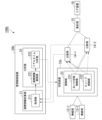
- FIG. 1 is a diagram for explaining an overview of the overall configuration and processing of a mobile NW system in an embodiment.
- FIG. It is a diagram showing an example of the configuration of a mobile NW system in a first embodiment.
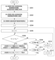
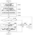
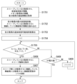
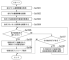
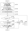
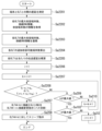
- It is a flowchart which shows an example of the flow of sleep processing performed by the management control device in a 1st embodiment.
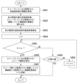
- It is a flowchart which shows an example of the flow of sleep processing performed by the management control device in a 1st embodiment.
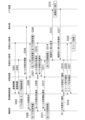
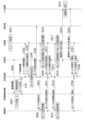
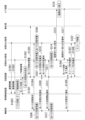
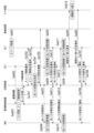
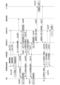
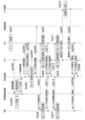
- FIG. 2 is a sequence diagram showing an example of a detailed flow of sleep processing executed by the mobile NW system in the first embodiment.
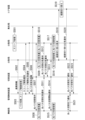
- 2 is a flowchart illustrating an example of the flow of sleep cancellation processing executed by the management control device in the first embodiment.
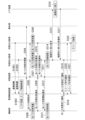
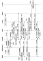
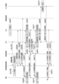
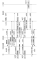
- FIG. 2 is a sequence diagram illustrating an example of a detailed flow of sleep wakeup processing executed by the mobile NW system in the first embodiment. It is a figure showing the example of composition of the mobile NW system in the modification of a 1st embodiment. It is a figure showing the example of composition of the mobile NW system in the modification of a 1st embodiment.
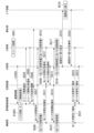
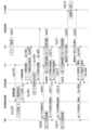
- FIG. 7 is a sequence diagram showing an example of a detailed flow of sleep processing executed by the mobile NW system in a modification of the first embodiment.
- FIG. 7 is a sequence diagram illustrating an example of a detailed flow of sleep wakeup processing executed by the mobile NW system in a modification of the first embodiment. It is a figure showing the example of composition of the mobile NW system in a 2nd embodiment.
- FIG. 12 is a flowchart illustrating an example of the flow of sleep processing executed by the management control device in the second embodiment. 12 is a flowchart illustrating an example of the flow of sleep processing executed by the management control device in the second embodiment.
- FIG. 7 is a sequence diagram illustrating an example of a detailed flow of sleep processing executed by the mobile NW system in the second embodiment. 12 is a flowchart illustrating an example of the flow of sleep release processing executed by the management control device in the second embodiment.
- FIG. 7 is a sequence diagram showing an example of a detailed flow of sleep wakeup processing executed by the mobile NW system in the second embodiment.
- FIG. 7 is a sequence diagram showing an example of a detailed flow of sleep processing executed by the mobile NW system in a modification of the second embodiment.
- FIG. 12 is a sequence diagram showing an example of a detailed flow of sleep wakeup processing executed by the mobile NW system in a modification of the second embodiment.
- 12 is a flowchart illustrating an example of the flow of sleep processing executed by the management control device in the third embodiment.
- 12 is a flowchart illustrating an example of the flow of sleep processing executed by the management control device in the third embodiment.
- FIG. 7 is a sequence diagram showing an example of a detailed flow of sleep processing executed by the mobile NW system in the third embodiment.
- 12 is a flowchart illustrating an example of a sleep cancellation process executed by the management control device in the third embodiment.
- FIG. 12 is a sequence diagram showing an example of a detailed flow of sleep wakeup processing executed by the mobile NW system in the third embodiment.
- FIG. 12 is a sequence diagram showing an example of a detailed flow of sleep processing executed by the mobile NW system in a modification of the third embodiment.
- FIG. 12 is a sequence diagram showing an example of a detailed flow of sleep wakeup processing executed by the mobile NW system in a modification of the third embodiment. It is a figure showing the example of composition of the mobile NW system in a 4th embodiment.
- 12 is a flowchart illustrating an example of the flow of sleep processing executed by the management control device in the fourth embodiment.
- 12 is a flowchart illustrating an example of the flow of sleep processing executed by the management control device in the fourth embodiment.
- FIG. 12 is a sequence diagram showing an example of a detailed flow of sleep processing executed by the mobile NW system in the fourth embodiment.
- FIG. 12 is a flowchart illustrating an example of the flow of sleep cancellation processing executed by the management control device in the fourth embodiment.
- FIG. 12 is a sequence diagram showing an example of a detailed flow of sleep wakeup processing executed by the mobile NW system in the fourth embodiment.
- FIG. 12 is a sequence diagram showing an example of a detailed flow of sleep processing executed by the mobile NW system in a modification of the fourth embodiment.
- FIG. 13 is a sequence diagram showing an example of a detailed flow of sleep wakeup processing executed by the mobile NW system in a modification of the fourth embodiment.
- 1 is a diagram for explaining an overview of the overall configuration and processing of a wired NW system in an embodiment.
- FIG. It is a figure showing an example of composition of a wired NW system in a 5th embodiment.
- FIG. 12 is a flowchart illustrating an example of the flow of sleep processing executed by the management control device in the fifth embodiment.
- 12 is a flowchart illustrating an example of the flow of sleep processing executed by the management control device in the fifth embodiment.
- FIG. 12 is a sequence diagram showing an example of a detailed flow of sleep processing executed by the wired NW system in the fifth embodiment.
- 12 is a flowchart illustrating an example of the flow of sleep release processing executed by the management control device in the fifth embodiment.
- FIG. 12 is a sequence diagram showing an example of a detailed flow of sleep cancellation processing executed by the wired NW system in the fifth embodiment. It is a figure showing the example of composition of the wired NW system in the modification of a 5th embodiment.
- FIG. 12 is a sequence diagram showing an example of a detailed flow of sleep processing executed by the wired NW system in a modification of the fifth embodiment.
- FIG. 12 is a sequence diagram showing an example of a detailed flow of sleep cancellation processing executed by the wired NW system in a modification of the fifth embodiment.
- 12 is a flowchart illustrating an example of the flow of sleep processing executed by the management control device in the sixth embodiment.
- 12 is a flowchart illustrating an example of the flow of sleep processing executed by the management control device in the sixth embodiment.
- FIG. 12 is a sequence diagram showing an example of a detailed flow of sleep processing executed by the wired NW system in the sixth embodiment.
- 12 is a flowchart illustrating an example of the flow of sleep release processing executed by the management control device in the sixth embodiment.
- FIG. 12 is a sequence diagram showing an example of a detailed flow of sleep cancellation processing executed by the wired NW system in the sixth embodiment.
- FIG. 12 is a sequence diagram showing an example of a detailed flow of sleep processing executed by the wired NW system in a modification of the sixth embodiment.
- FIG. 12 is a sequence diagram showing an example of a detailed flow of sleep cancellation processing executed by the wired NW system in a modification of the sixth embodiment. It is a flowchart which shows an example of the flow of sleep processing performed by the management control device in a 7th embodiment.
- FIG. 12 is a sequence diagram showing an example of a detailed flow of sleep processing executed by the wired NW system in the seventh embodiment.
- 13 is a flowchart illustrating an example of the flow of sleep cancellation processing executed by the management control device in the seventh embodiment.
- FIG. 12 is a sequence diagram showing an example of a detailed flow of sleep cancellation processing executed by the wired NW system in the seventh embodiment.
- FIG. 12 is a sequence diagram showing an example of a detailed flow of sleep processing executed by the wired NW system in a modification of the seventh embodiment.
- FIG. 12 is a sequence diagram showing an example of a detailed flow of sleep processing executed by the wired NW system in a modification of the seventh embodiment.
- FIG. 12 is a sequence diagram showing an example of a detailed flow of sleep cancellation processing executed by the wired NW system in a modification of the seventh embodiment. It is a figure showing the example of composition of the wired NW system in an 8th embodiment. 12 is a flowchart showing an example of the flow of sleep processing executed by the management control device in the eighth embodiment. 12 is a flowchart showing an example of the flow of sleep processing executed by the management control device in the eighth embodiment. FIG. 12 is a sequence diagram showing an example of a detailed flow of sleep processing executed by the wired NW system in the eighth embodiment. 12 is a flowchart illustrating an example of the flow of sleep cancellation processing executed by the management control device in the eighth embodiment. FIG.
- FIG. 12 is a sequence diagram showing an example of a detailed flow of sleep cancellation processing executed by the wired NW system in the eighth embodiment.
- FIG. 12 is a sequence diagram showing an example of a detailed flow of sleep processing executed by the wired NW system in a modification of the eighth embodiment.
- FIG. 12 is a sequence diagram illustrating an example of a detailed flow of sleep cancellation processing executed by the wired NW system in a modification of the eighth embodiment.
- FIG. 1 is a diagram for explaining an overview of the overall configuration and processing of a mobile NW system in an embodiment.
- a mobile NW system is an example of a communication system.
- the mobile NW system is, for example, a fifth generation mobile communication system (hereinafter referred to as "5G").
- the mobile NW system includes one or more wireless stations 12 , a switching device 13 , a plurality of distributed stations 14 , an aggregation station 15 , a core device 16 , and a management control device 20 .
- Optical signals are transmitted between the wireless station 12 and the switching device 13, between the switching device 13 and the distributed station 14, between the distributed station 14 and the central station 15, and between the central station 15 and the core device 16. Connected by optical fiber.
- the switching device 13 and the management control device 20 and the distribution station 14 and the management control device 20 are connected by electric wires or optical fibers that transmit electrical signals.
- FIG. 1 shows a case where there are four wireless stations 12 and two distributed stations 14. Note that, although a plurality of switching devices 13 may be provided, the following description will be made using one switching device as an example.
- Each wireless station 12 is equipped with one or more antennas and performs wireless communication with the terminal 11. For example, each wireless station 12 receives a signal transmitted from the terminal 11 and transmits the received signal to the distributed station 14 connected via the switching device 13. Each wireless station 12 transmits the signal received via the switching device 13 to the terminal 11.
- the radio station 12 is, for example, an RU (Radio Unit) in the 5G communication standard.
- the wireless station 12 is one aspect of a terminal accommodation station.
- the switching device 13 is provided between the wireless station 12 and the distributed station 14.
- the switching device 13 performs optical path switching according to instructions from the management control device 20.
- An optical path is a route for optical signals.
- the switching device 13 switches the connection between the wireless station 12 and the distributed station 14 by switching the optical path.
- the distributed station 14 receives the uplink signal transmitted by the wireless station 12 via the switching device 13.
- the distributed station 14 transmits the downlink signal to the wireless station 12 via the switching device 13.
- the upstream signal is a signal transmitted by the terminal 11, and the downstream signal is a signal destined for the terminal 11.
- Each distributed station 14 transitions to a sleep state according to instructions from the management control device 20.
- the sleep state is a state in which it is possible to save power by stopping some functions.
- the distributed station 14 is, for example, a DU (Distributed Unit) in the 5G communication standard.
- Information that the management control device 20 acquires from the distributed station 14 is referred to as cooperation information.
- the cooperation information is information indicating the state of communication between each distributed station 14 and the terminal 11.
- the distributed station 14 is one aspect of a communication station.
- the cooperation information includes, for example, information regarding the number of terminals 11 accommodated in each distributed station 14 (hereinafter referred to as "number of accommodated terminals").
- the cooperation information includes, for example, the maximum number of terminals that the distributed station 14 can accommodate.
- the maximum number of terminals that the distributed station 14 can accommodate is the maximum number that the distributed station 14 can accommodate.
- the cooperation information includes, for example, information on the wireless station 12 to which the optical path distribution station 14 is connected (hereinafter referred to as "connected wireless station information").
- the cooperation information includes, for example, information regarding the processing load of the distributed station 14 (hereinafter referred to as "processing load information").
- the processing load information may be, for example, information on the memory usage rate of the distributed station 14 or information on the usage rate of the CPU (Central Processing Unit).
- the cooperation information includes, for example, information regarding processing delays for each distributed station 14 (hereinafter referred to as "processing delay information").
- processing delay information information regarding processing delays for each distributed station 14
- delay information information regarding transmission delays between the terminal 11 and each distributed station 14
- the aggregation station 15 aggregates uplink signals transmitted by each distributed station 14.
- the aggregation station 15 distributes downlink signals.
- the aggregation station 15 is, for example, a CU (Centralized Unit) in the 5G communication standard.
- the core device 16 performs signal processing on the upstream signals aggregated by the aggregation station 15.
- the core device 16 transmits a signal obtained as a result of performing signal processing on the upstream signal to an external network.
- Core device 16 receives signals from an external network.
- the core device 16 performs predetermined signal processing on signals received from an external network.
- the core device 16 transmits a signal obtained as a result of performing signal processing on a signal received from an external network to the aggregation station 15 as a downlink signal.
- Signal processing is, for example, the transfer of user data in a UPF (User Plane Function) of the 5G core network.
- UPF User Plane Function
- the management control device 20 acquires cooperation information from the distributed station 14. The management control device 20 determines whether optical path switching and sleep control are necessary based on the acquired cooperation information. The management control device 20 performs optical path switching control processing and sleep control processing when it is determined that optical path switching and sleep control are necessary.
- the optical path switching control process is a process for switching the optical path between the wireless station 12 and the distributed station 14. For example, the management control device 20 instructs the switching device 13 to control switching of the optical path between the wireless station 12 and the distributed station 14.
- the sleep control process is a process that causes the distributed station 14 to execute sleep or cancel sleep.
- the upper diagram in FIG. 1 represents the connection state of the mobile NW system before optical path switching
- the lower diagram in FIG. 1 represents the connection state of the mobile NW system after optical path switching.
- the upper diagram of FIG. 1 shows an example in which wireless stations 12-1 and 12-2 are connected to distributed station 14-1, and wireless stations 12-3 and 12-4 are connected to distributed station 14-2. has been done.
- the management control device 20 determines whether to perform optical path switching control processing based on the cooperation information collected from each distributed station 14.
- the management control device 20 determines to perform the optical path switching control process when there is a distributed station 14 that can transition to a sleep state.
- the distributed station 14 that can enter the sleep state is, for example, the distributed station 14 that does not accommodate the terminal 11.
- the management control device 20 determines not to perform the optical path switching control process when there is no distributed station 14 that can transition to the sleep state.
- the management control device 20 determines to perform the optical path switching control process, it instructs the switching device 13 to switch the optical path.
- the switching device 13 switches the optical path between the wireless station 12 and the distributed station 14 according to instructions from the management control device 20. After completing the optical path switching, the switching device 13 notifies the management control device 20 of the completion of the optical path switching.
- the management control device 20 Upon receiving the notification of completion of optical path switching from the switching device 13, the management control device 20 transmits a sleep permission notification to the distributed station 14 that can transition to the sleep state.
- the sleep permission notification is a signal containing an instruction to cause the distributed station 14 to enter a sleep state. As a result, the distributed station 14 that can go into a sleep state goes into a sleep state.
- the lower diagram in FIG. 1 shows an example in which wireless stations 12-1 to 12-4 are connected to distributed station 14-1, and distributed station 14-2 is in a sleep state.
- the terminal 11 connected to a distributed station 14 that can go into a sleep state is connected to another distributed station 14 based on the cooperation information collected from each distributed station 14. This causes the distributed station 14 that can go into a sleep state to go into a sleep state.
- the distributed station 14 that can transition to a sleep state will be referred to as a switching source distributed station, and the distributed station 14 that will become the new connection destination of the terminal 11 connected to the switching source distributed station will be referred to as a switching destination distributed station.
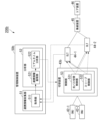
- FIG. 2 is a diagram showing a configuration example of the mobile NW system 100 in the first embodiment.
- the mobile NW system 100 in the first embodiment includes one or more wireless stations 12, a switching device 13, a plurality of distributed stations 14, an aggregation station 15, a core device 16, and a management control device 20.
- the wireless station 12, switching device 13, distributed station 14, aggregation station 15, and core device 16 have been described with reference to FIG. 1, so their description will be omitted.
- the management control device 20 includes a cooperation information collection section 21, an analysis section 22, and a control section 23.
- the cooperation information collection unit 21 includes an acquisition unit 211.
- the acquisition unit 211 collects cooperation information from the distributed station 14 at a predetermined period.
- the analysis section 22 includes a cooperation information storage section 221 and a real-time analysis section 222.
- the cooperation information storage unit 221 records the collected cooperation information in a predetermined storage device.
- the real-time analysis unit 222 analyzes the state of communication between each distributed station 14 and the terminal 11, such as the amount of change in the number of connected distributed stations 14 per unit time, based on the cooperation information. Specifically, the real-time analysis unit 222 determines whether optical path switching and sleep control are necessary based on the cooperation information.
- the real-time analysis unit 222 determines that optical path switching and sleep control are necessary when all the terminals 11 accommodated by the switching source distributed station can be accommodated in another distributed station 14. In this case, the real-time analysis unit 222 notifies the control unit 23 of information indicating the distributed station 14 to which the optical path is to be switched and information indicating the distributed station 14 to be put to sleep.
- the real-time analysis unit 222 determines that optical path switching and sleep control are necessary when the number of terminals 11 accommodated by the distributed station 14 exceeds the maximum number of terminals accommodated. In this case, the real-time analysis unit 222 notifies the control unit 23 of information indicating the distributed station 14 to which the optical path is to be switched and information indicating the distributed station 14 to be woken from sleep.
- the control unit 23 includes an optical path switching control unit 231 and a sleep control unit 232.
- the optical path switching control unit 231 determines the distributed station 14 to which the optical path is to be switched, based on the analysis result of the real-time analysis unit 222, and instructs the switching device 13 to switch the optical path. For example, the optical path switching control unit 231 determines the distributed station 14 to which the optical path is to be switched, based on the information indicating the distributed station 14 to which the optical path is to be switched, which is notified from the real-time analysis unit 222 .
- the sleep control unit 232 causes the distributed station 14 to execute sleep or cancel sleep based on the analysis result of the real-time analysis unit 222.
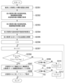
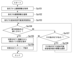
- FIG. 3 is a flowchart showing an example of the flow of sleep processing executed by the management control device 20 in the first embodiment.
- the cooperation information includes at least information on the number of terminals accommodated in each distributed station 14 and information on the maximum number of terminals accommodated.
- the process flow in FIG. 3 is repeatedly executed at a predetermined cycle.
- the acquisition unit 211 acquires cooperation information from each distributed station 14 (step S101).
- the acquisition unit 211 stores the acquired cooperation information for each distributed station 14 in the cooperation information storage unit 221 (step S102).
- the real-time analysis unit 222 calculates the number of additional terminals that each distributed station 14 can accommodate based on the cooperation information for each distributed station 14 accumulated in the cooperation information storage unit 221 (step S103).
- the number of terminals that can be additionally accommodated refers to the number of terminals 11 that can be additionally accommodated in addition to the number of terminals that the distributed station 14 currently accommodates.
- the number of additionally accommodable terminals can be obtained by subtracting the number of accommodated terminals from the maximum number of accommodated terminals.
- the real-time analysis unit 222 determines whether the first switching condition is satisfied (step S104).
- the first switching condition is a condition indicating that the optical path between the wireless station 12 and the distributed station 14 needs to be switched. This is more than the number of terminals accommodated by the distributed station 14.
- the real-time analysis unit 222 determines that the first switching condition is satisfied (step S104-YES), it notifies the control unit 23 of an optical path switching instruction and a sleep control instruction.
- the optical path switching control unit 231 instructs the switching device 13 to switch the optical path of the wireless station 12 connected to the switching source distributed station based on the optical path switching instruction notified from the real-time analysis unit 222 (step S105). Specifically, the optical path switching control unit 231 instructs the optical path of the wireless station 12 connected to the switching source distributed station to go toward the switching destination distributed station.
- the sleep control unit 232 transmits a sleep permission notification to the switching source distributed station (step S106). For example, the sleep control unit 232 may transmit a sleep instruction to the switching source distributed station when an optical path switching completion notification is obtained from the wireless station 12 connected to the switching source distributed station and the switching destination distributed station. .
- the optical path switching completion notification is a signal that includes content indicating that optical path switching has been completed. This allows the switching source distributed station to transition to a sleep state.
- step S104 if the real-time analysis unit 222 determines that the first switching condition is not satisfied (step S104-NO), it determines whether there are other distributed stations 14 (step S107).
- the other distributed stations 14 are, for example, distributed stations 14 that have not been compared with the distributed station 14 that is the target of sleep determination.
- step S107-NO the process ends.
- the real-time analysis unit 222 determines that there are other distributed stations 14 (step S107-YES), it selects information on the number of additionally accommodated terminals of the other distributed stations 14 (step S108). The real-time analysis unit 222 executes the process of step S104 again using information on the number of additionally accommodated terminals of the other selected distributed stations 14.
- FIG. 4 is a flowchart showing an example of the flow of sleep processing executed by the management control device 20 in the first embodiment. Note that the process shown in FIG. 4 will be described in more detail with respect to the process shown in FIG.
- the acquisition unit 211 acquires information on the maximum number of accommodating terminals, connected wireless station information, and number of accommodating terminals of each distributed station from each distributed station 14 as cooperation information (step S201).
- the acquisition unit 211 stores the acquired cooperation information for each distributed station 14 in the cooperation information storage unit 221 (step S202).
- the real-time analysis unit 222 calculates the number of additional terminals that each distributed station 14 can accommodate based on the cooperation information for each distributed station 14 accumulated in the cooperation information storage unit 221 (step S203).
- the real-time analysis unit 222 assigns a value of 1 to the constant i (step S204).
- i represents the distributed station 14-i that is the switching destination.
- the distributed station 14-1 becomes the switching destination distributed station.
- i has a value of 1 ⁇ i ⁇ I.
- I is the total number of distributed stations 14.
- the real-time analysis unit 222 assigns the value of (i+1) to k (step S205).
- k represents the distributed station 14-k that is the switching source.
- the distributed station 14-2 becomes the switching source distributed station.
- k has a value of 2 ⁇ k ⁇ K.
- the real-time analysis unit 222 determines whether U i ⁇ u i >u k is satisfied (step S206).
- U i represents the maximum number of terminals accommodated by the distributed station 14-i
- u i represents the number of terminals accommodated by the distributed station 14-i
- u k represents the number of terminals accommodated by the distributed station 14-k.
- the condition indicated by U i ⁇ u i >u k is a specific example of the first switching condition.
- the maximum number of terminals accommodated by the distributed station 14-1 is 1000
- the maximum number of terminals accommodated by the distributed station 14-1 is 100
- the maximum number of terminals accommodated by the distributed station 14-2 is 800
- the number of terminals accommodated by the distributed station 14-2 is 200.
- U 1 ⁇ u 1 >u 2 becomes 900>200, and the first switching condition is satisfied. If the real-time analysis unit 222 determines that the first switching condition (for example, U i - u i > u k ) is satisfied (step S206-YES), the real-time analysis unit 222 sends an optical path switching instruction and a sleep control instruction to the control unit. Notify 23.
- the first switching condition for example, U i - u i > u k
- the optical path switching control unit 231 instructs the switching device 13 to switch the optical path of the wireless station 12 connected to the distributed station 14-k based on the optical path switching instruction notified from the real-time analysis unit 222 (Ste S207). Specifically, the optical path switching control unit 231 switches the optical path of the wireless station 12 connected to the distributed station 14-k (for example, the distributed station 14-2) to the distributed station 14-i, which is the switching destination distributed station. (for example, distributed station 14-1).
- the sleep control unit 232 transmits a sleep permission notification to the distributed station 14-k (for example, the distributed station 14-2) (step S208).
- the maximum number of terminals accommodated by the distributed station 14-1 is 1000
- the maximum number of terminals accommodated by the distributed station 14-1 is 500
- the maximum number of terminals accommodated by the distributed station 14-2 is 800
- step S209-YES determines whether i is the maximum value (step S211). If the real-time analysis unit 222 determines that i is the maximum value (step S211-YES), it ends the process.
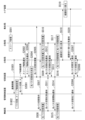
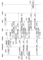
- FIG. 5 is a sequence diagram showing an example of a detailed flow of sleep processing executed by the mobile NW system 100 in the first embodiment.
- the distributed station 14-1 is the switching destination distributed station
- the distributed station 14-2 is the switching source distributed station.
- the explanation will be given by referring to the switching destination distributed station 14-1 and the switching source distributed station 14-2.
- the acquisition unit 211 of the management control device 20 acquires cooperation information from the switching destination distributed station 14-1 and the switching source distributed station 14-2 at a predetermined period (step S301, step S302).
- the acquisition unit 211 stores the acquired collaboration information in the collaboration information storage unit 221.
- the real-time analysis section 222 performs optical path switching and sleep control judgment (step S303).
- the optical path switching and sleep control determination in step S303 is a determination as to whether the first switching condition is satisfied in step S104.
- the real-time analysis unit 222 instructs the optical path switching control unit 231 to perform optical path switching control, and instructs the sleep control unit 232 to perform sleep control.
- the optical path switching control unit 231 notifies the switching device 13 and the aggregation station 15 of the optical path switching destination information (step S304).
- the optical path switching destination information is information regarding the switching destination of the optical path.
- the optical path switching destination information includes information indicating the switching destination distributed station 14-1 as the optical path switching destination.
- the switching device 13 instructs the wireless station 12 connected to the switching source distributed station 14-2 to switch the optical path to the switching destination distributed station 14-1, and is instructed to switch so that the optical path is connected to the wireless station 12 connected to the switching source distributed station 14-2, and the switching source distributed station 14-2 is instructed not to set up an optical path. do.
- the wireless station 12 connected to the switching source distributed station 14-2, the switching destination distributed station 14-1, and the switching source distributed station 14-2 prepare for optical path switching (steps S306, S307, and S308).
- the wireless station 12 connected to the switching source distributed station 14-2, the switching destination distributed station 14-1, and the switching source distributed station 14-2 transmit an optical path switching response notification to the switching device 13 (step S309 , step S310 and step S311).
- the optical path switching response notification is a signal that includes content indicating that optical path switching destination information has been received.
- the switching device 13 When the switching device 13 receives an optical path switching response notification from the wireless station 12 connected to the switching source distributed station 14-2, the switching destination distributed station 14-1, and the switching source distributed station 14-2, the switching device 13 performs switching.
- An optical path switching start notification is transmitted to the wireless station 12 connected to the wireless station 12 connected to the original distributed station 14-2 and the switching destination distributed station 14-1 (step S312).
- the optical path switching start notification is a signal containing a command to start optical path switching.
- the wireless station 12 connected to the switching source distributed station 14-2 and the switching destination distributed station 14-1 switch optical paths in response to receiving the optical path switching start notification (step S313, step S314). Through this process, the optical path of the wireless station 12 connected to the switching source distributed station 14-2 is switched so as to go toward the switching destination distributed station 14-1. That is, the wireless station 12 and the switching destination distributed station 14-1 become communicable.
- the switching destination distributed station 14-1 transmits a path switching request to the core device 16 (step S315).
- the path switching request is a signal that includes content requesting switching of the communication path in the core device 16.
- the core device 16 switches the route in response to receiving the route switching request (step S316).
- the core device 16 transmits a route switching response notification to the switching destination distributed station 14-1 (step S317).
- the path switching response notification is a signal that includes content indicating that switching of the communication path in the core device 16 has been completed.
- the wireless station 12 transmits an optical path switching completion notification to the management control device 20 (step S318).
- the optical path switching completion notification is a signal that includes content indicating that optical path switching has been completed.
- the switching destination distributed station 14-1 transmits an optical path switching completion notification to the management control device 20 (step S319).
- the sleep control unit 232 When the sleep control unit 232 receives the optical path switching completion notification from the destination of the optical path switching start notification, it transmits a sleep permission notification to the switching source distributed station 14-2 (step S320). When the switching source distributed station 14-2 receives the sleep permission notification from the management control device 20, it transmits a sleep response notification to the management control device 20 (step S321).
- the sleep response notification is a signal that includes content indicating that the sleep permission notification has been received. After transmitting the sleep response notification, the switching source distributed station 14-2 shifts to a sleep state (step S322).
- FIG. 6 is a flowchart illustrating an example of the flow of sleep release processing executed by the management control device 20 in the first embodiment.
- the acquisition unit 211 acquires the number of accommodated terminals and information on the sleeping distributed station 14-k from each distributed station 14 as cooperation information (step S401).
- the acquisition unit 211 notifies the analysis unit 22 of the acquired number of accommodated terminals and information on the sleeping distributed station 14-k.
- the real-time analysis unit 222 reads information on the maximum number of terminals accommodated by each distributed station 14 and information on the wireless station 12 that was connected to the sleeping distributed station 14-k from the cooperation information storage unit 221 (step S402).
- the real-time analysis unit 222 calculates the number of additional terminals that each distributed station 14 can accommodate based on the cooperation information for each distributed station 14 accumulated in the cooperation information storage unit 221 (step S403).
- the real-time analysis unit 222 assigns a value of 1 to the constant i (step S404).
- the real-time analysis unit 222 determines whether U i ⁇ u i is satisfied (step S405).
- the condition represented by U i ⁇ u i is a specific example of the first sleep release condition. If the real-time analysis unit 222 determines that the first sleep cancellation condition (for example, U i ⁇ u i ) is satisfied (step S405-YES), the real-time analysis unit 222 cancels the sleep state of the sleeping distributed station 14-k and controls the optical path. It is determined that switching is necessary.
- the real-time analysis unit 222 notifies the control unit 23 of the determination result.
- the sleep control unit 232 transmits an instruction to wake up the sleeping distributed station 14-k based on the determination result (step S406).
- the optical path switching control unit 231 acquires information on the wireless station 12 that was connected to the distributed station 14-k before sleep from the information acquired in the process of step S402.
- the optical path switching control unit 231 instructs the wireless station 12 that was connected to the distributed station 14-k before sleep to change the connection to the distributed station 14-k.
- step S405 if the real-time analysis unit 222 determines that the first sleep release condition (for example, U i ⁇ u i ) is not satisfied (step S405 - NO), it determines whether i is the maximum value or not. is determined (step S408). If the real-time analysis unit 222 determines that i is the maximum value (step S408-YES), it ends the process.
- the first sleep release condition for example, U i ⁇ u i
- step S408-NO if the real-time analysis unit 222 determines that i is not the maximum value (step S408-NO), it adds a value of 1 to the value of i (step S409). After that, the real-time analysis unit 222 executes the process of step S405 again.
- the process in FIG. 6 will be explained using specific numerical values.
- the maximum number of terminals accommodated by the distributed station 14-1 is 1000
- the number of terminals accommodated by the distributed station 14-1 is 800
- the maximum number of terminals accommodated by the distributed station 14-1 is 800. It is assumed that the maximum number of terminals accommodated by the distributed station 14-2 is 800, and the number of terminals accommodated by the distributed station 14-2 is 1000.
- the real-time analysis unit 222 executes the process of step S405 again.
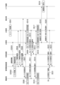
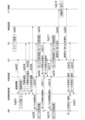
- FIG. 7 is a sequence diagram showing an example of a detailed flow of the sleep wakeup process executed by the mobile NW system 100 in the first embodiment. In the explanation of FIG. 7, it is assumed that the distributed station 14-2 is in a sleep state.
- the distributed station 14-2 is in a sleep state (step S501).
- the acquisition unit 211 of the management control device 20 acquires cooperation information from the distributed station 14-1 at a predetermined period (step S502).
- the acquisition unit 211 stores the acquired collaboration information in the collaboration information storage unit 221.
- the real-time analysis section 222 performs optical path switching and sleep control judgment (step S503).
- the optical path switching and sleep control determination in step S503 is based on whether the sleep release condition is satisfied. Here, it is assumed that the sleep release condition is satisfied.
- the sleep control unit 232 of the management control device 20 transmits a sleep release notification to the distributed station 14-2 (step S504).
- the sleep release notification is a signal that includes content indicating that the sleep state will be released.
- the distributed station 14-2 transmits a sleep release response notification to the management control device 20 (step S505).
- the sleep release response notification is a signal that includes content indicating that the sleep release notification has been received.
- the optical path switching control unit 231 notifies the switching device 13 and the aggregation station 15 of the optical path switching destination information (step S506).
- the switching device 13 is notified of the optical path switching destination information from the management control device 20, it instructs the wireless station 12, the distributed station 14-1, and the distributed station 14-2 to switch the optical path (step S507).
- the wireless station 12, the distributed station 14-1, and the distributed station 14-2 prepare for optical path switching (step S508, step S509, and step S510).
- the wireless station 12, the distributed station 14-1, and the distributed station 14-2 complete the preparation for switching the optical path, they transmit an optical path switching response notification indicating that the preparation for switching is completed to the switching device 13 (step S511, step S512 and step S513).
- the switching device 13 When the switching device 13 receives an optical path switching response notification from the wireless station 12, the distributed station 14-1, and the distributed station 14-2, the switching device 13 switches the wireless station 12, the distributed station 14-1, and the distributed station 14-2.
- An optical path switching start notification is transmitted to (step S514).
- the wireless station 12, the distributed station 14-1, and the distributed station 14-2 switch optical paths in response to receiving the optical path switching start notification (step S515, step S516, and step S517).
- the distributed station 14-1 transmits a path switching request to the core device 16 (step S518).
- the core device 16 switches the route in response to receiving the route switching request (step S519).
- the core device 16 transmits a route switching response notification to the distributed station 14-1 (step S520).
- the wireless station 12 transmits an optical path switching completion notification to the management control device 20 (step S521).
- the distributed station 14-1 transmits an optical path switching completion notification to the management control device 20 (step S522).
- the distributed station 14-2 transmits an optical path switching completion notification to the management control device 20 (step S523).
- one or more wireless stations 12 that perform wireless communication with one or more terminals 11 and a plurality of wireless stations 12 connected to the one or more wireless stations 12 via the switching device 13 a cooperation information collection unit 21 that acquires cooperation information indicating the state of communication between the plurality of distributed stations 14 and one or more terminals 11 at a predetermined period;
- a cooperation information collection unit 21 that acquires cooperation information indicating the state of communication between the plurality of distributed stations 14 and one or more terminals 11 at a predetermined period;
- It includes an optical path switching control section 231 that controls, and a sleep control section 232 that causes a distributed station capable of sleep to enter a sleep state after switching the optical path.
- optical path switching and sleep control are performed while analyzing the load on each distributed station 14. Therefore, it is possible to increase the power saving effect without deteriorating communication quality.
- FIG. 8 is a diagram showing a configuration example of the mobile NW system 100a in Modification 1 of the first embodiment.
- the mobile NW system 100a includes one or more wireless stations 12, a switching device 13, a plurality of distributed stations 14, an aggregation station 15, a core device 16, a management control device 20, and a wireless controller 30a.
- a wireless controller 30a is provided between the management control device 20 and the distributed station 14.
- the wireless controller 30a acquires cooperation information from each distributed station 14 at a predetermined period through wireless communication.
- the wireless controller 30a transmits the acquired cooperation information to the management control device 20 by wireless communication.
- the wireless controller 30a may receive a sleep control instruction from the management control device 20 and transmit it to the switching source distributed station. With this configuration, cooperation information can be collected by wireless communication.
- FIG. 9 is a diagram showing a configuration example of the mobile NW system 100b in the second modification of the first embodiment.
- the mobile NW system 100b includes one or more wireless stations 12, a switching device 13b, a plurality of distributed stations 14, an aggregation station 15, a core device 16, and a management control device 20b.
- the switching device 13b includes a control unit 23, and the management control device 20b does not include a control unit 23.
- the real-time analysis unit 222 of the management control device 20b notifies the switching device 13b of the analysis result. Note that the real-time analysis unit 222 may notify the switching device 13b of the analysis results only when optical path switching and sleep control are performed.
- the control unit 23 of the switching device 13b performs optical path switching control processing and sleep control processing based on the analysis result notified from the management control device 20b.
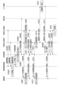
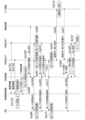
- FIG. 10 is a sequence diagram showing an example of a detailed flow of sleep processing executed by the mobile NW system 100b in the second modification of the first embodiment.
- the same processes as in FIG. 5 are given the same reference numerals as in FIG. 5, and the description thereof will be omitted.
- the distributed station 14-1 is the switching destination distributed station
- the distributed station 14-2 is the switching source distributed station.
- the explanation will be given by referring to the switching destination distributed station 14-1 and the switching source distributed station 14-2.
- the real-time analysis unit 222 instructs the switching device 13b to perform optical path switching control and sleep control if the first switching condition is satisfied (step S601).
- the switching device 13b receives the instruction transmitted from the management control device 20b.
- the optical path switching control unit 231 of the switching device 13b determines the optical path switching destination from the information included in the received instruction (step S602).
- the optical path switching control unit 231 notifies the aggregation station 15 of the optical path switching destination information (step S603). Thereafter, the optical path switching control unit 231 performs optical path switching for the wireless station 12 connected to the switching source distributed station 14-2, the switching destination distributed station 14-1, and the switching source distributed station 14-2. (Step S604). After that, the processes from step S306 to step S317 are executed.
- the wireless station 12 transmits an optical path switching completion notification to the switching device 13b (step S605). Note that the wireless station 12 may also transmit the optical path switching completion notification to the management control device 20b.
- the switching destination distributed station 14-1 transmits an optical path switching completion notification to the switching device 13b (step S606). Note that the wireless station 12 may also transmit the optical path switching completion notification to the management control device 20b.
- the sleep control unit 232 included in the switching device 13b When the sleep control unit 232 included in the switching device 13b receives the optical path switching completion notification from the destination of the optical path switching start notification, it transmits a sleep permission notification to the switching source distributed station 14-2 (step S607 ). When the switching source distributed station 14-2 receives the sleep permission notification from the switching device 13b, it transmits a sleep response notification to the switching device 13b (step S608). After transmitting the sleep response notification, the switching source distributed station 14-2 shifts to a sleep state (step S322).
- FIG. 11 is a sequence diagram showing an example of a detailed flow of the sleep wakeup process executed by the mobile NW system 100b in the second modification of the first embodiment.
- the same processes as in FIG. 7 are given the same reference numerals as in FIG. 7, and the description thereof will be omitted.
- the distributed station 14-2 is in a sleep state.
- the real-time analysis unit 222 instructs the switching device 13b to perform optical path switching control and sleep control when the sleep release condition is satisfied (step S701).
- the switching device 13b receives the instruction transmitted from the management control device 20b.
- the sleep control unit 232 of the switching device 13b transmits a sleep release notification to the distributed station 14-2 based on the information included in the received instruction (step S702).
- the distributed station 14-2 transmits a sleep release response notification to the switching device 13b (step S703).
- the optical path switching control unit 231 of the switching device 13b determines the optical path switching destination from the information included in the received instruction (step S704).
- the optical path switching control unit 231 of the switching device 13b notifies the aggregation station 15 of the optical path switching destination information (step S705). After that, the processes from step S507 to step S520 are executed.
- the wireless station 12 transmits an optical path switching completion notification to the switching device 13b (step S706).
- the distributed station 14-1 transmits an optical path switching completion notification to the switching device 13b (step S707).
- the distributed station 14-2 transmits an optical path switching completion notification to the switching device 13b (step S708).
- the second embodiment differs in configuration from the first embodiment in that the cooperation information further includes processing load information (for example, memory usage rate information or CPU usage rate information for each distributed station). .
- processing load information for example, memory usage rate information or CPU usage rate information for each distributed station.
- FIG. 12 is a diagram showing a configuration example of a mobile NW system 100c in the second embodiment.
- the mobile NW system 100c in the second embodiment includes one or more wireless stations 12, a switching device 13, a plurality of distributed stations 14, an aggregation station 15, a core device 16, and a management control device 20c.
- the management control device 20c includes a cooperation information collection section 21c, an analysis section 22c, and a control section 23.
- the cooperation information collection unit 21c includes an acquisition unit 211 and a distributed station monitoring unit 212c.
- the distributed station monitoring unit 212c monitors each distributed station 14 and measures the memory usage rate for each distributed station 14.
- the distributed station monitoring unit 212c outputs information on the memory usage rate measured for each distributed station 14 to the analysis unit 22c as coordination information.
- the analysis section 22c includes a cooperation information storage section 221 and a real-time analysis section 222c.
- the real-time analysis unit 222c analyzes the communication state in the mobile NW system 100c, such as the amount of change in the number of connections of the distributed stations 14 per unit time, based on the cooperation information. Specifically, the real-time analysis unit 222c divides the memory usage rate by the current number of accommodated terminals to roughly estimate the memory usage rate per terminal.
- the real-time analysis unit 222c multiplies the number of accommodated terminals of other distributed stations 14 by the memory usage rate per unit of the target distributed station 14, and determines that the memory usage rate does not exceed 100% and that the When the number of terminals accommodated by the station 14 is smaller than the number of terminals that can be additionally accommodated by the target distributed station 14, optical path switching and sleep are determined.
- FIG. 13 is a flowchart showing an example of the flow of sleep processing executed by the management control device 20c in the second embodiment.
- the same processes as in FIG. 3 are given the same reference numerals as in FIG. 3, and the description thereof will be omitted.
- the cooperation information collection unit 21c acquires cooperation information from each distributed station 14 (step S801). Specifically, the acquisition unit 211 acquires at least information on the number of accommodated terminals, information on the maximum number of accommodated terminals, etc. from each distributed station 14 as cooperation information. Furthermore, the distributed station monitoring unit 212c measures the memory usage rate for each distributed station 14. The cooperation information collection unit 21c accumulates the acquired cooperation information for each distributed station 14 in the cooperation information storage unit 221 (step S802). Specifically, the cooperation information collection unit 21c collects information on the memory usage rate of each distributed station 14 in addition to cooperation information including at least information on the number of accommodated terminals, information on the maximum number of accommodated terminals, etc. from each distributed station 14. The information is stored in the cooperation information storage unit 221 as cooperation information.
- the real-time analysis unit 222c calculates the number of additional terminals that each distributed station 14 can accommodate based on the cooperation information for each distributed station 14 accumulated in the cooperation information storage unit 221 (step S803). Further, the real-time analysis unit 222c roughly estimates the memory usage rate of each distributed station 14 based on the cooperation information for each distributed station 14 accumulated in the cooperation information storage unit 221 (step S804).
- the real-time analysis unit 222c determines whether the second switching condition is satisfied (step S805).
- the second switching condition is a condition indicating that it is necessary to switch the optical path between the wireless station 12 and the distributed station 14. For example, the number of additional terminals that can be accommodated by a certain distributed station 14 is determined to be The number of terminals accommodated by the distributed station 14 must be greater than the number of terminals accommodated, and the memory usage rate must not exceed 100%.
- step S805-YES If the real-time analysis unit 222c determines that the second switching condition is satisfied (step S805-YES), the processes from step S105 onwards are executed. On the other hand, if the real-time analysis unit 222c determines that the second switching condition is not satisfied (step S805-NO), the processes from step S107 onwards are executed.
- FIG. 14 is a flowchart showing an example of the flow of sleep processing executed by the management control device 20c in the second embodiment. Note that the process shown in FIG. 14 will be described in more detail as the process shown in FIG. 13. In FIG. 14, the same processes as in FIG. 4 are given the same reference numerals as in FIG. 4, and the description thereof will be omitted.
- the acquisition unit 211 acquires information on the maximum number of terminals accommodated in each distributed station, connected wireless station information, and number of accommodated terminals from each distributed station 14 as cooperation information. Furthermore, the distributed station monitoring unit 212c acquires information on the memory usage rate of each distributed station 14 (step S901).
- the acquisition unit 211 stores the acquired cooperation information for each distributed station 14 in the cooperation information storage unit 221.
- the distributed station monitoring unit 212c accumulates the acquired information on the memory usage rate of each distributed station 14 as cooperation information (step S902).
- the real-time analysis unit 222c calculates the number of additional terminals that each distributed station 14 can accommodate based on the cooperation information for each distributed station 14 accumulated in the cooperation information storage unit 221 (step S903). Further, the real-time analysis unit 222c roughly estimates the memory usage rate for each distributed station 14 based on the cooperation information for each distributed station 14 accumulated in the cooperation information storage unit 221 (step S904).
- the real-time analysis unit 222c assigns a value of 1 to the constant i (step S905).
- the real-time analysis unit 222c assigns the value (i+1) to k (step S906).
- the real-time analysis unit 222c determines whether 100-M i >m i ⁇ u k and U i -u i >u k are satisfied (step S907).
- M i represents the memory usage rate of the distributed station 14-i
- m i represents the memory usage rate of each distributed station 14.
- m i is calculated in the process of step S904.
- the conditions represented by 100-M i >m i ⁇ u k and U i -u i >u k are specific examples of the second switching condition.
- step S907-YES If the real-time analysis unit 222c determines that the second switching condition is satisfied (step S907-YES), it executes the processes from step S207 onwards. On the other hand, if the real-time analysis unit 222c determines that the second switching condition is not satisfied (step S907-NO), it executes the processes from step S209 onwards.
- the process in FIG. 14 will be explained using specific numerical values.
- the maximum number of terminals accommodated by the distributed station 14-1 is 1000
- the number of terminals accommodated by the distributed station 14-1 is 100
- the memory usage rate M1 of the distributed station 14-1 is 20%
- the number of terminals accommodated by the distributed station 14-2 is 200
- the memory usage rate M2 of the distributed station 14-2 is 30%.
- m 1 represents an estimated value of the memory usage rate per distributed station 14-1
- m 2 represents an estimated value of the memory usage rate per distributed station 14-2.
- 100-M i >m i ⁇ u k and U i -u i >u k are 180>40 and 900>200.
- the real-time analysis unit 222c determines that the second switching condition is satisfied. Therefore, the real-time analysis unit 222c makes a switching decision to connect the wireless station 12 connected to the distributed station 14-2 to the distributed station 14-1, and switches the wireless station 12 connected to the distributed station 14-2 to a sleep state so as to cause the distributed station 14-2 to enter the sleep state. to decide.
- the real-time analysis unit 222c notifies the optical path switching control unit 231 of the result of determining whether to connect the wireless station 12 connected to the distributed station 14-2 to the distributed station 14-1, and switches the wireless station 12 connected to the distributed station 14-2 to the distributed station 14-1.
- the sleep control unit 232 is notified of the sleep determination result so as to shift to the sleep state.
- the optical path switching control unit 231 controls optical path switching so that the wireless station 12 connected to the distributed station 14-2 is connected to the distributed station 14-1 according to the notification from the real-time analysis unit 222c.
- the sleep control unit 232 controls sleep so that the distributed station 14-2 enters a sleep state in accordance with the notification from the real-time analysis unit 222c.
- FIG. 15 is a sequence diagram showing an example of a detailed flow of sleep processing executed by the mobile NW system 100c in the second embodiment.
- the same processes as in FIG. 5 are given the same reference numerals as in FIG. 5, and the description thereof will be omitted.
- the distributed station 14-1 is the switching destination distributed station
- the distributed station 14-2 is the switching source distributed station.
- the explanation will be given by referring to the switching destination distributed station 14-1 and the switching source distributed station 14-2.
- the cooperation information collection unit 21c of the management control device 20c acquires cooperation information from the switching destination distributed station 14-1 and the switching source distributed station 14-2 at a predetermined period (step S1001, step S1002).
- the cooperation information acquired in step S1001 and step S1002 includes at least information on the number of accommodated terminals, information on the maximum number of accommodated terminals, etc., as well as information on the memory usage rate of each distributed station 14. shall be.
- the collaboration information collection unit 21c stores the acquired collaboration information in the collaboration information storage unit 221.
- the real-time analysis unit 222c When the collaboration information is accumulated in the collaboration information storage unit 221, the real-time analysis unit 222c performs optical path switching and sleep control determination (step S1003).
- the optical path switching and sleep control determination in step S1003 is a determination as to whether the second switching condition is satisfied in step S805.
- FIG. 16 is a flowchart illustrating an example of the flow of sleep cancellation processing executed by the management control device 20c in the second embodiment.
- the same processes as in FIG. 6 are given the same reference numerals as in FIG. 6, and the description thereof will be omitted.
- the acquisition unit 211 acquires information about the number of accommodated terminals and the sleeping distributed station 14-k from each distributed station 14 as cooperation information. Furthermore, the distributed station monitoring unit 212c acquires information on the memory usage rate of each distributed station 14 as cooperation information (step S1101). The acquisition unit 211 notifies the analysis unit 22c of the acquired number of accommodated terminals, information on the sleeping distributed station 14-k, and information on the memory usage rate.
- the real-time analysis unit 222c of the analysis unit 22c reads information on the maximum number of terminals accommodated in each distributed station 14 and information on the wireless stations 12 that were connected to the sleeping distributed station 14-k from the cooperation information storage unit 221 (Ste S1102).
- the real-time analysis unit 222c calculates the number of additional terminals that each distributed station 14 can accommodate based on the acquired cooperation information for each distributed station 14 (step S1103).
- the real-time analysis unit 222c assigns a value of 1 to the constant i (step S1104).
- the real-time analysis unit 222c determines whether either U i ⁇ u i or T1 ⁇ M i is satisfied (step S1105).
- the condition represented by U i ⁇ u i or T1 ⁇ M i is a specific example of the second sleep release condition.
- T1 ⁇ M i means that the memory usage rate M i of the distributed station 14-i exceeds the threshold T1 (for example, a predetermined value such as 80, 90, 100%, etc.). do.
- step S1105-YES If the real-time analysis unit 222c determines that the second sleep release condition (for example, U i ⁇ u i or T1 ⁇ M i ) is satisfied (step S1105-YES), the real-time analysis unit 222c switches the optical path and goes to sleep. It is determined that it is necessary to wake up the distributed station 14-k.
- the second sleep release condition for example, U i ⁇ u i or T1 ⁇ M i
- the real-time analysis unit 222c notifies the control unit 23 of the determination result. Thereafter, the processing from step S406 onwards is executed. On the other hand, if the real-time analysis unit 222c determines that the second sleep release condition (for example, U i ⁇ u i or T1 ⁇ M i ) is not satisfied (step S1105-NO), the real-time analysis unit 222c executes the process of step S408. Execute.
- the second sleep release condition for example, U i ⁇ u i or T1 ⁇ M i
- FIG. 17 is a sequence diagram showing an example of a detailed flow of the sleep wakeup process executed by the mobile NW system 100c in the second embodiment.
- the same processes as in FIG. 7 are given the same reference numerals as in FIG. 7, and the description thereof will be omitted.
- the distributed station 14-2 is in a sleep state.
- the distributed station 14-2 is in a sleep state (step S501).
- the cooperation information collection unit 21c of the management control device 20c acquires cooperation information from the distributed station 14-1 at a predetermined period (step S1201).
- the cooperation information acquired in step S1201 includes at least information on the number of accommodated terminals, information on the maximum number of accommodated terminals, and the like, as well as information on the memory usage rate of each distributed station 14.
- the collaboration information collection unit 21c stores the acquired collaboration information in the collaboration information storage unit 221.
- the real-time analysis unit 222c When the collaboration information is accumulated in the collaboration information storage unit 221, the real-time analysis unit 222c performs optical path switching and sleep control determination (step S1202).
- the optical path switching and sleep control determination in step S1202 is based on whether the sleep release condition is satisfied. Here, it is assumed that the sleep release condition is satisfied. If the sleep release condition is satisfied, the real-time analysis unit 222c executes the processing from step S504 onwards.
- the management control device 20c further acquires information on the memory usage rate of each distributed station 14 as cooperation information, and determines whether or not optical path switching is necessary based on the cooperation information. to judge.
- the management control device 20c controls switching of the optical path between one or more wireless stations 12 and the plurality of distributed stations 14 when it is determined that switching of the optical path is necessary.
- the management control device 20c causes the distributed station capable of sleep to enter a sleep state. As a result, optical path switching and sleep control are performed while analyzing the load on each distributed station 14. Therefore, it is possible to increase the power saving effect without deteriorating communication quality.
- the management control device 20c has shown a configuration in which the cooperation information is directly acquired from the distributed station 14.
- the management control device 20c may acquire cooperation information via another device.
- the other device is, for example, a wireless controller.
- the mobile NW system 100c is newly equipped with a wireless controller 30a, and the wireless controller 30a is provided between the management control device 20c and the distributed station 14.
- the wireless controller 30a acquires cooperation information from each distributed station 14 at a predetermined period through wireless communication.
- the wireless controller 30a transmits the acquired cooperation information to the management control device 20c via wireless communication.
- the wireless controller 30a may receive a sleep control instruction from the management control device 20c and transmit it to the switching source distributed station. With this configuration, cooperation information can be collected by wireless communication.
- the management control device 20c performs the optical path switching control process and the sleep control process.
- the switching device 13 may be configured to perform optical path switching control processing and sleep control processing.
- the switching device 13 includes the control unit 23, and the management control device 20c does not include the control unit 23.
- the real-time analysis unit 222c of the management control device 20c notifies the switching device 13 of the analysis result.
- the real-time analysis unit 222c may notify the switching device 13 of the analysis results only when optical path switching and sleep control are performed.
- the control unit 23 of the switching device 13 performs optical path switching control processing and sleep control processing based on the analysis result notified from the management control device 20c.
- FIG. 18 is a sequence diagram showing an example of a detailed flow of sleep processing executed by the mobile NW system 100c in Modification 2 of the second embodiment.
- the same processes as in FIG. 15 are given the same reference numerals as in FIG. 15, and the description thereof will be omitted.
- the real-time analysis unit 222c instructs the switching device 13b to perform optical path switching control and sleep control when the second switching condition is satisfied (step S1301).
- the switching device 13b receives the instruction transmitted from the management control device 20c.
- the optical path switching control unit 231 of the switching device 13b determines the optical path switching destination from the information included in the received instruction (step S1302).
- the optical path switching control unit 231 notifies the aggregation station 15 of the optical path switching destination information (step S1303). Thereafter, the optical path switching control unit 231 performs optical path switching for the wireless station 12 connected to the switching source distributed station 14-2, the switching destination distributed station 14-1, and the switching source distributed station 14-2. (Step S1304). After that, the processes from step S306 to step S317 are executed.
- the wireless station 12 transmits an optical path switching completion notification to the switching device 13b (step S1305). Note that the wireless station 12 may also transmit the optical path switching completion notification to the management control device 20c.
- the switching destination distributed station 14-1 transmits an optical path switching completion notification to the switching device 13 (step S1306). Note that the wireless station 12 may also transmit the optical path switching completion notification to the management control device 20c.
- the sleep control unit 232 included in the switching device 13b When the sleep control unit 232 included in the switching device 13b receives the optical path switching completion notification from the destination of the optical path switching start notification, it transmits a sleep permission notification to the switching source distributed station 14-2 (step S1307 ).
- the switching source distributed station 14-2 receives the sleep permission notification from the switching device 13, it transmits a sleep response notification to the switching device 13b (step S1308). After transmitting the sleep response notification, the switching source distributed station 14-2 shifts to a sleep state (step S322).
- FIG. 19 is a sequence diagram showing an example of a detailed flow of the sleep wakeup process executed by the mobile NW system 100c in Modification 2 of the second embodiment.
- the same processes as in FIG. 17 are given the same reference numerals as in FIG. 17, and the description thereof will be omitted.
- the distributed station 14-2 is in a sleep state.
- step S1201 the real-time analysis unit 222c instructs the switching device 13b to perform optical path switching control and sleep control when the sleep release condition is satisfied.
- Step S1401 The switching device 13b receives the instruction transmitted from the management control device 20c.
- the sleep control unit 232 of the switching device 13b transmits a sleep release notification to the distributed station 14-2 based on the information included in the received instruction (step S1402).
- the distributed station 14-2 transmits a sleep release response notification to the switching device 13b (step S1403).
- the optical path switching control unit 231 of the switching device 13b determines the optical path switching destination from the information included in the received instruction (step S1404).
- the optical path switching control unit 231 of the switching device 13b notifies the aggregation station 15 of the optical path switching destination information (step S1405). After that, the processes from step S507 to step S520 are executed.
- the wireless station 12 transmits an optical path switching completion notification to the switching device 13b (step S1406).
- the distributed station 14-1 transmits an optical path switching completion notification to the switching device 13b (step S1407).
- the distributed station 14-2 transmits an optical path switching completion notification to the switching device 13b (step S1408).
- the third embodiment is characterized in that the cooperation information further includes processing load information (for example, memory usage rate information or CPU usage rate information for each distributed station) and processing delay information for each distributed station.
- processing load information for example, memory usage rate information or CPU usage rate information for each distributed station
- processing delay information for each distributed station.
- the configuration is different from the second embodiment. Note that the system configuration is the same as in the second embodiment.
- information on memory usage rate for each distributed station will be explained as an example of processing load information.
- the management control device 20c determines optical path switching and sleep based on information on the number of terminals for each distributed station 14, information on memory usage rate for each distributed station 14, and processing delay information for each distributed station 14. For example, the distributed station monitoring unit 212c monitors each distributed station 14 and measures the memory usage rate for each distributed station 14. Further, the distributed station monitoring unit 212c monitors each distributed station 14 and collects processing delay information for each distributed station 14. The distributed station monitoring unit 212c outputs information on the memory usage rate measured for each distributed station 14 and processing delay information for each distributed station 14 as coordination information to the analysis unit 22c.
- FIG. 20 is a flowchart showing an example of the flow of sleep processing executed by the management control device 20c in the third embodiment.
- the same processes as in FIG. 13 are given the same reference numerals as in FIG. 13, and the description thereof will be omitted.
- the cooperation information collection unit 21c acquires cooperation information from each distributed station 14 (step S1501). Specifically, the acquisition unit 211 acquires at least information on the number of accommodated terminals, information on the maximum number of accommodated terminals, etc. from each distributed station 14 as cooperation information. Further, the distributed station monitoring unit 212c measures the memory usage rate for each distributed station 14 and acquires processing delay information for each distributed station 14. The cooperation information collection unit 21c accumulates the acquired cooperation information for each distributed station 14 in the cooperation information storage unit 221 (step S1502). Specifically, the cooperation information collection unit 21c collects information on the memory usage rate of each distributed station 14 in addition to cooperation information including at least information on the number of accommodated terminals, information on the maximum number of accommodated terminals, etc. from each distributed station 14. Information and processing delay information for each distributed station 14 are stored in the cooperation information storage unit 221 as cooperation information.
- the real-time analysis unit 222c calculates the number of additional terminals that each distributed station 14 can accommodate based on the cooperation information for each distributed station 14 accumulated in the cooperation information storage unit 221 (step S1503). Furthermore, the real-time analysis unit 222c roughly estimates the memory usage rate of each distributed station 14 based on the cooperation information for each distributed station 14 accumulated in the cooperation information storage unit 221 (step S1504).
- the real-time analysis unit 222c determines whether the third switching condition is satisfied (step S1505).
- the third switching condition is a condition indicating that the optical path between the wireless station 12 and the distributed station 14 needs to be switched.
- the number of terminals accommodated by the distributed station 14 must be greater than the number of terminals accommodated by the distributed station 14, the memory usage rate must not exceed 100%, and the processing delay of the distributed station 14 that is subject to sleep determination must not exceed a threshold value.
- step S1505-YES If the real-time analysis unit 222c determines that the third switching condition is satisfied (step S1505-YES), the processes from step S105 onwards are executed. On the other hand, if the real-time analysis unit 222c determines that the third switching condition is not satisfied (step S1505-NO), the processes from step S107 onwards are executed.
- FIG. 21 is a flowchart showing an example of the flow of sleep processing executed by the management control device 20c in the third embodiment. Note that the process shown in FIG. 21 will be described in more detail as the process shown in FIG. 20. In FIG. 21, the same processing as in FIG. 14 is given the same reference numeral as in FIG. 14, and the description thereof will be omitted.
- the acquisition unit 211 acquires information on the maximum number of terminals accommodated in each distributed station, connected wireless station information, and number of accommodated terminals from each distributed station 14 as cooperation information. Further, the distributed station monitoring unit 212c acquires memory usage rate information and processing delay information of each distributed station 14 (step S1601).
- the acquisition unit 211 stores the acquired cooperation information for each distributed station 14 in the cooperation information storage unit 221. Furthermore, the distributed station monitoring unit 212c accumulates the acquired memory usage rate information and processing delay information of each distributed station 14 as cooperation information (step S1602).
- the real-time analysis unit 222c calculates the number of additional terminals that each distributed station 14 can accommodate based on the cooperation information for each distributed station 14 accumulated in the cooperation information storage unit 221 (step S1603). Furthermore, the real-time analysis unit 222c roughly estimates the memory usage rate for each distributed station 14 based on the cooperation information for each distributed station 14 accumulated in the cooperation information storage unit 221 (step S1604).
- the real-time analysis unit 222c assigns a value of 1 to the constant i (step S1605).
- the real-time analysis unit 222c assigns the value of (i+1) to k (step S1606).
- the real-time analysis unit 222c determines whether 100-M i >m i ⁇ u k , U i ⁇ u i >u k , and T>t i are satisfied (step S1607).
- T represents a threshold value
- t i in the third embodiment represents a processing delay of the distributed station 14-i.
- the conditions represented by 100-M i >m i ⁇ u k , U i -u i >u k , and T>t i are specific examples of the third switching condition.
- step S1607-YES If the real-time analysis unit 222c determines that the third switching condition is satisfied (step S1607-YES), it executes the processes from step S207 onwards. On the other hand, if the real-time analysis unit 222c determines that the third switching condition is not satisfied (step S1607-NO), it executes the processes from step S209 onwards.
- FIG. 22 is a sequence diagram showing an example of a detailed flow of sleep processing executed by the mobile NW system 100c in the third embodiment.
- the same processes as in FIG. 15 are given the same reference numerals as in FIG. 15, and the description thereof will be omitted.
- the distributed station 14-1 is the switching destination distributed station
- the distributed station 14-2 is the switching source distributed station.
- the explanation will be given by referring to the switching destination distributed station 14-1 and the switching source distributed station 14-2.
- the cooperation information collection unit 21c of the management control device 20c acquires cooperation information from the switching destination distributed station 14-1 and the switching source distributed station 14-2 at a predetermined period (step S1701, step S1702).
- the cooperation information acquired in step S1701 and step S1702 includes at least information on the number of accommodated terminals, information on the maximum number of accommodated terminals, etc., as well as information on the memory usage rate of each distributed station 14 and information on the memory usage rate of each distributed station 14. It is assumed that processing delay information for each time is included.
- the collaboration information collection unit 21c stores the acquired collaboration information in the collaboration information storage unit 221.
- the real-time analysis unit 222c When the collaboration information is accumulated in the collaboration information storage unit 221, the real-time analysis unit 222c performs optical path switching and sleep control judgment (step S1703).
- the optical path switching and sleep control determination in step S1703 is a determination as to whether the third switching condition is satisfied in step S1505. Here, it is assumed that the third switching condition in step S1505 is satisfied. If the fifth switching condition is satisfied, the real-time analysis unit 222c executes the processing from step S304 onwards.
- FIG. 23 is a flowchart showing an example of the flow of the sleep cancellation process executed by the management control device 20c in the third embodiment.
- the same processes as in FIG. 16 are given the same reference numerals as in FIG. 16, and the description thereof will be omitted.
- the acquisition unit 211 acquires information about the number of accommodated terminals and the sleeping distributed station 14-k from each distributed station 14 as cooperation information. Furthermore, the distributed station monitoring unit 212c acquires information on the memory usage rate for each distributed station 14 and processing delay information for each distributed station 14 as cooperation information (step S1751). The acquisition unit 211 notifies the analysis unit 22c of the acquired number of accommodated terminals, information on the sleeping distributed station 14-k, memory usage rate information, and processing delay information for each distributed station 14.
- the real-time analysis unit 222c of the analysis unit 22c reads information on the maximum number of terminals accommodated in each distributed station 14 and information on the wireless stations 12 that were connected to the sleeping distributed station 14-k from the cooperation information storage unit 221 (Ste S1752).
- the real-time analysis unit 222c calculates the number of additional terminals that each distributed station 14 can accommodate based on the acquired cooperation information for each distributed station 14 (step S1753).
- the real-time analysis unit 222c assigns a value of 1 to the constant i (step S1754).
- the real-time analysis unit 222c determines whether any of U i ⁇ u i , T1 ⁇ M i , or T ⁇ t i is satisfied (step S1755).
- the condition represented by U i ⁇ u i , T1 ⁇ M i , or T ⁇ t i is a specific example of the third sleep release condition. In the third sleep release condition, T ⁇ t i means that the processing delay of the distributed station 14-i exceeds the threshold.
- the real-time analysis unit 222c notifies the control unit 23 of the determination result. Thereafter, the processing from step S406 onwards is executed. On the other hand, if the real-time analysis unit 222c determines that the third sleep release condition (for example, U i ⁇ u i , or T1 ⁇ M i , or T ⁇ t i ) is not satisfied (step S1755-NO ), the process of step S408 is executed.
- the third sleep release condition for example, U i ⁇ u i , or T1 ⁇ M i , or T ⁇ t i
- FIG. 24 is a sequence diagram showing an example of a detailed flow of the sleep wakeup process executed by the mobile NW system 100c in the third embodiment.
- the same processes as in FIG. 17 are given the same reference numerals as in FIG. 17, and the description thereof will be omitted.
- the distributed station 14-2 is in a sleep state.
- the distributed station 14-2 is in a sleep state (step S501).
- the cooperation information collection unit 21c of the management control device 20c acquires cooperation information from the distributed station 14-1 at a predetermined period (step S1801). Note that the cooperation information acquired in step S1801 includes memory usage rate information and processing delay information for each distributed station 14.
- the collaboration information collection unit 21c stores the acquired collaboration information in the collaboration information storage unit 221.
- the real-time analysis unit 222c When the collaboration information is accumulated in the collaboration information storage unit 221, the real-time analysis unit 222c performs optical path switching and sleep control judgment (step S1802).
- the optical path switching and sleep control determination in step S1802 is based on whether the sleep release condition is satisfied. Here, it is assumed that the sleep release condition is satisfied. If the sleep release condition is satisfied, the real-time analysis unit 222c executes the processing from step S504 onwards.
- the management control device 20c further acquires memory usage rate information for each distributed station 14 and processing delay information for each distributed station 14 as coordination information. Then, based on the cooperation information, it is determined whether or not to switch the optical path.
- the management control device 20c controls switching of the optical path between one or more wireless stations 12 and the plurality of distributed stations 14 when it is determined that switching of the optical path is necessary. Furthermore, after the optical path is switched, the management control device 20c causes the distributed station capable of sleep to enter a sleep state. As a result, optical path switching and sleep control are performed while analyzing the load on each distributed station 14. Therefore, it is possible to increase the power saving effect without deteriorating communication quality.
- the management control device 20c has shown a configuration in which the cooperation information is directly acquired from the distributed station 14.
- the management control device 20c may acquire cooperation information via another device.
- the other device is, for example, a wireless controller.
- the mobile NW system 100c is newly equipped with a wireless controller 30a, and the wireless controller 30a is provided between the management control device 20c and the distributed station 14.
- the wireless controller 30a acquires cooperation information from each distributed station 14 at a predetermined period through wireless communication.
- the wireless controller 30a transmits the acquired cooperation information to the management control device 20c via wireless communication.
- the wireless controller 30a may receive a sleep control instruction from the management control device 20c and transmit it to the switching source distributed station. With this configuration, cooperation information can be collected by wireless communication.
- the management control device 20c performs the optical path switching control process and the sleep control process.
- the switching device 13 may be configured to perform optical path switching control processing and sleep control processing.
- the switching device 13 includes the control unit 23, and the management control device 20c does not include the control unit 23.
- the real-time analysis unit 222c of the management control device 20c notifies the switching device 13 of the analysis result.
- the real-time analysis unit 222c may notify the switching device 13 of the analysis results only when optical path switching and sleep control are performed.
- the control unit 23 of the switching device 13 performs optical path switching control processing and sleep control processing based on the analysis result notified from the management control device 20c.
- FIG. 25 is a sequence diagram showing an example of a detailed flow of sleep processing executed by the mobile NW system 100c in Modification 2 of the third embodiment.
- the same processing as in FIG. 22 is given the same reference numeral as in FIG. 22, and the description thereof will be omitted.
- the real-time analysis unit 222c instructs the switching device 13b to perform optical path switching control and sleep control when the third switching condition is satisfied (step S1901).
- the switching device 13b receives the instruction transmitted from the management control device 20c.
- the optical path switching control unit 231 of the switching device 13b determines the optical path switching destination from the information included in the received instruction (step S1902).
- the optical path switching control unit 231 notifies the aggregation station 15 of the optical path switching destination information (step S1903). Thereafter, the optical path switching control unit 231 performs optical path switching for the wireless station 12 connected to the switching source distributed station 14-2, the switching destination distributed station 14-1, and the switching source distributed station 14-2. (Step S1904). After that, the processes from step S306 to step S317 are executed.
- the wireless station 12 transmits an optical path switching completion notification to the switching device 13b (step S1905). Note that the wireless station 12 may also transmit the optical path switching completion notification to the management control device 20c.
- the switching destination distributed station 14-1 transmits an optical path switching completion notification to the switching device 13 (step S1906). Note that the wireless station 12 may also transmit the optical path switching completion notification to the management control device 20c.
- the sleep control unit 232 included in the switching device 13b When the sleep control unit 232 included in the switching device 13b receives the optical path switching completion notification from the destination of the optical path switching start notification, it transmits a sleep permission notification to the switching source distributed station 14-2 (step S1907 ).
- the switching source distributed station 14-2 receives the sleep permission notification from the switching device 13, it transmits a sleep response notification to the switching device 13b (step S1908). After transmitting the sleep response notification, the switching source distributed station 14-2 shifts to a sleep state (step S322).
- FIG. 26 is a sequence diagram illustrating an example of a detailed flow of the sleep wakeup process executed by the mobile NW system 100c in Modification 2 of the third embodiment.
- the same processes as in FIG. 23 are given the same reference numerals as in FIG. 23, and the description thereof will be omitted.
- step S501 After the processes of step S501, step S1801, and step S1802 are executed, the real-time analysis unit 222c instructs the switching device 13b to perform optical path switching control and sleep control when the sleep cancellation condition is satisfied. (Step S2001).
- the switching device 13b receives the instruction transmitted from the management control device 20c.
- the sleep control unit 232 of the switching device 13b transmits a sleep release notification to the distributed station 14-2 based on the information included in the received instruction (step S2002). In response to receiving the sleep release notification, the distributed station 14-2 transmits a sleep release response notification to the switching device 13b (step S2003).
- the optical path switching control unit 231 of the switching device 13b determines the optical path switching destination from the information included in the received instruction (step S2004).
- the optical path switching control unit 231 of the switching device 13b notifies the aggregation station 15 of the optical path switching destination information (step S2005). After that, the processes from step S507 to step S520 are executed.
- the wireless station 12 transmits an optical path switching completion notification to the switching device 13b (step S2006).
- the distributed station 14-1 transmits an optical path switching completion notification to the switching device 13b (step S2007).
- the distributed station 14-2 transmits an optical path switching completion notification to the switching device 13b (step S2008).
- the fourth embodiment differs in configuration from the first embodiment in that the cooperation information further includes information on transmission delays between the terminal 11 and each distributed station 14.
- FIG. 27 is a diagram showing a configuration example of a mobile NW system 100d in the fourth embodiment.
- a mobile NW system 100d in the fourth embodiment includes one or more wireless stations 12, a switching device 13, a plurality of distributed stations 14, an aggregation station 15, a core device 16, and a management control device 20d.
- the management control device 20d includes a cooperation information collection section 21d, an analysis section 22d, and a control section 23.
- the cooperation information collection unit 21d includes an acquisition unit 211 and a delay measurement unit 213d.
- the delay measurement unit 213d measures the transmission delay between the terminal 11 and each distributed station 14. For example, the delay measurement unit 213d measures the transmission delay between the terminal 11 and each distributed station 14 based on the RTT (Round-Trip Time) obtained as a result of transmitting the Ping.
- the delay measurement unit 213d outputs information on the propagation delay measured for each distributed station 14 to the analysis unit 22d as coordination information.
- the analysis section 22d includes a cooperation information storage section 221 and a real-time analysis section 222d.
- the real-time analysis unit 222d analyzes the communication state in the mobile NW system 100d, such as the amount of change in the number of connections of the distributed stations 14 per unit time, based on the cooperation information. Specifically, the real-time analysis unit 222d divides the delay time by the current number of accommodated terminals to roughly estimate the delay time per terminal.
- the real-time analysis unit 222d multiplies the number of accommodated terminals of other distributed stations 14 by the delay time per unit of the target distributed station 14, and determines that the delay time does not exceed the threshold and that If the number of accommodated terminals is smaller than the number of terminals that can be additionally accommodated by the target distributed station 14, optical path switching and sleep are determined.
- FIG. 28 is a flowchart showing an example of the flow of sleep processing executed by the management control device 20d in the fourth embodiment.
- the same processing as in FIG. 3 is given the same reference numeral as in FIG. 3, and the description thereof will be omitted.
- the delay measurement unit 213d measures the transmission delay between the terminal 11 and each distributed station 14 (step S2101).
- the cooperation information collection unit 21d acquires cooperation information from each distributed station 14 (step S2102). Specifically, the acquisition unit 211 acquires at least information on the number of accommodated terminals, information on the maximum number of accommodated terminals, etc. from each distributed station 14 as cooperation information.
- the cooperation information collection unit 21d accumulates the acquired cooperation information for each distributed station 14 in the cooperation information storage unit 221 (step S2103). Specifically, the cooperation information collection unit 21d collects cooperation information from each distributed station 14 including at least information on the number of accommodated terminals, information on the maximum number of accommodated terminals, etc., as well as information on the relationship between the terminal 11 and each distributed station 14.
- the information on the transmission delay between the two is stored in the cooperation information storage unit 221 as cooperation information.
- the real-time analysis unit 222d calculates the number of additional terminals that each distributed station 14 can accommodate based on the cooperation information for each distributed station 14 accumulated in the cooperation information storage unit 221 (step S2104). Further, the real-time analysis unit 222d roughly estimates the delay time of each distributed station 14 based on the information on the transmission delay between the terminal 11 and each distributed station 14 stored in the cooperation information storage unit 221 (step S2105). .
- the real-time analysis unit 222d determines whether the fourth switching condition is satisfied (step S2106).
- the fourth switching condition is a condition indicating that the optical path between the wireless station 12 and the distributed station 14 needs to be switched.
- the number of terminals accommodated by the distributed station 14 is greater than the number of terminals accommodated by the distributed station 14, and the transmission delay does not exceed a threshold value.
- step S2106-YES If the real-time analysis unit 222d determines that the fourth switching condition is satisfied (step S2106-YES), the processes from step S105 onwards are executed. On the other hand, if the real-time analysis unit 222d determines that the second switching condition is not satisfied (step S2106-NO), the processes from step S107 onwards are executed.
- FIG. 29 is a flowchart showing an example of the flow of sleep processing executed by the management control device 20d in the fourth embodiment. Note that the process shown in FIG. 29 will be described in more detail as the process shown in FIG. 28. In FIG. 29, the same processes as in FIG. 4 are given the same reference numerals as in FIG. 4, and the description thereof will be omitted.
- the delay measurement unit 213d measures the transmission delay between the terminal 11 and each distributed station 14 (step S2201).
- the acquisition unit 211 acquires information on the maximum number of accommodating terminals, connected wireless station information, and number of accommodating terminals of each distributed station from each distributed station 14 as cooperation information (step S2202).
- the acquisition unit 211 stores the acquired cooperation information for each distributed station 14 in the cooperation information storage unit 221 (step S2203).
- the real-time analysis unit 222d calculates the number of additional terminals that each distributed station 14 can accommodate based on the cooperation information for each distributed station 14 accumulated in the cooperation information storage unit 221 (step S2204). Furthermore, the real-time analysis unit 222d roughly estimates the transmission delay for each distributed station 14 based on the measured information on the transmission delay between the terminal 11 and each distributed station 14 (step S2205).
- the real-time analysis unit 222d divides the transmission delay value T i of the distributed station 14-i obtained in the process of step S2201 by the number of terminals u i accommodated in the distributed station 14-i (T i /u i ), the transmission delay t i for each distributed station 14-i is roughly estimated.
- the real-time analysis unit 222d assigns a value of 1 to the constant i (step S2206).
- the real-time analysis unit 222d assigns the value (i+1) to k (step S2207).
- the real-time analysis unit 222d determines whether or not U i ⁇ u i >u k and T>t i ⁇ (u i +u k ) are satisfied (step S2208).
- t i represents the transmission delay t i for each distributed station 14-i.
- the condition represented by U i ⁇ u i >u k and T>t i ⁇ (u i +u k ) is a specific example of the fourth switching condition. If the real-time analysis unit 222d determines that the fourth switching condition is satisfied (step S2208-YES), it executes the processes from step S207 onwards. On the other hand, if the real-time analysis unit 222d determines that the second switching condition is not satisfied (step S2208-NO), it executes the processes from step S209 onwards.
- FIG. 30 is a sequence diagram showing an example of a detailed flow of sleep processing executed by the mobile NW system 100d in the fourth embodiment.
- the same processes as in FIG. 5 are given the same reference numerals as in FIG. 5, and the description thereof will be omitted.
- the distributed station 14-1 is the switching destination distributed station
- the distributed station 14-2 is the switching source distributed station.
- the explanation will be given by referring to the switching destination distributed station 14-1 and the switching source distributed station 14-2.
- the cooperation information collection unit 21d of the management control device 20d acquires cooperation information from the switching destination distributed station 14-1 and the switching source distributed station 14-2 at a predetermined period (step S2301, step S2302).
- the cooperation information acquired in steps S2301 and S2302 includes at least information on the number of accommodated terminals, information on the maximum number of accommodated terminals, etc., and information on transmission delays between the terminal 11 and each distributed station 14. shall be included.
- the collaboration information collection unit 21d stores the acquired collaboration information in the collaboration information storage unit 221.
- the real-time analysis unit 222d When the collaboration information is accumulated in the collaboration information storage unit 221, the real-time analysis unit 222d performs optical path switching and sleep control judgment (step S2303).
- the optical path switching and sleep control determination in step S2303 is a determination as to whether the fourth switching condition is satisfied in step S2106. Here, it is assumed that the fourth switching condition in step S2106 is satisfied. If the fourth switching condition is satisfied, the real-time analysis unit 222d executes the processing from step S304 onwards.
- FIG. 31 is a flowchart illustrating an example of the flow of sleep cancellation processing executed by the management control device 20d in the fourth embodiment.
- the same processes as in FIG. 6 are given the same reference numerals as in FIG. 6, and the description thereof will be omitted.
- the delay measurement unit 213d measures the transmission delay between the terminal 11 and each distributed station 14 (step S2401).
- the acquisition unit 211 acquires the number of accommodated terminals and information on the sleeping distributed station 14-k from each distributed station 14 as cooperation information (step S2402).
- the acquisition unit 211 notifies the analysis unit 22d of the acquired number of accommodated terminals, information on the sleeping distributed station 14-k, and information on transmission delay.
- the real-time analysis unit 222d of the analysis unit 22d reads information on the maximum number of terminals accommodated in each distributed station 14 and information on the wireless station 12 that was connected to the sleeping distributed station 14-k from the cooperation information storage unit 221 (Ste S2403).
- the real-time analysis unit 222d calculates the number of additional terminals that each distributed station 14 can accommodate based on the acquired cooperation information for each distributed station 14 (step S2404).
- the real-time analysis unit 222d assigns a value of 1 to the constant i (step S2405).
- the real-time analysis unit 222d determines whether either U i ⁇ u i or T ⁇ t i is satisfied (step S2406).
- the condition represented by U i ⁇ u i or T ⁇ t i is a specific example of the fourth sleep release condition.
- T ⁇ t i means that the transmission delay between the terminal 11 and the distributed station 14-i exceeds a threshold value. That is, it means that the transmission delay t i of each distributed station 14-i exceeds the threshold value.
- step S2406-YES If the real-time analysis unit 222d determines that the fourth sleep cancellation condition (for example, U i ⁇ u i or T ⁇ t i ) is satisfied (step S2406-YES), the real-time analysis unit 222d switches the optical path and goes to sleep. It is determined that it is necessary to wake up the distributed station 14-k.
- the fourth sleep cancellation condition for example, U i ⁇ u i or T ⁇ t i
- the real-time analysis unit 222d notifies the control unit 23 of the determination result. Thereafter, the processing from step S406 onwards is executed. On the other hand, if the real-time analysis unit 222d determines that the fourth sleep cancellation condition (for example, U i ⁇ u i or T ⁇ t i ) is not satisfied (step S2406-NO), the real-time analysis unit 222d executes the process of step S408. Execute.
- the fourth sleep cancellation condition for example, U i ⁇ u i or T ⁇ t i
- FIG. 32 is a sequence diagram showing an example of a detailed flow of the sleep wakeup process executed by the mobile NW system 100d in the fourth embodiment.
- the same processes as in FIG. 7 are given the same reference numerals as in FIG. 7, and the description thereof will be omitted.
- the distributed station 14-2 is in a sleep state.
- the distributed station 14-2 is in a sleep state (step S501).
- the cooperation information collection unit 21d of the management control device 20d acquires cooperation information from the distributed station 14-1 at a predetermined period (step S2501).
- the cooperation information acquired in step S2501 includes at least information on the number of accommodated terminals, information on the maximum number of accommodated terminals, etc., as well as information on transmission delays between the terminal 11 and each distributed station 14. shall be taken as a thing.
- the collaboration information collection unit 21d stores the acquired collaboration information in the collaboration information storage unit 221.
- the real-time analysis unit 222d When the collaboration information is accumulated in the collaboration information storage unit 221, the real-time analysis unit 222d performs optical path switching and sleep control judgment (step S2502).
- the optical path switching and sleep control determination in step S2502 is based on whether the sleep release condition is satisfied. Here, it is assumed that the sleep release condition is satisfied. If the sleep release condition is satisfied, the real-time analysis unit 222d executes the processes from step S504 onwards.
- the management control device 20d further acquires information on the transmission delay between the terminal 11 and each distributed station 14 as cooperation information, and determines the optical path based on the cooperation information. Determine whether switching is necessary.
- the management control device 20d controls switching of the optical path between one or more wireless stations 12 and the plurality of distributed stations 14 when it is determined that switching of the optical path is necessary.
- the management control device 20d causes the distributed station capable of sleep to enter a sleep state. As a result, optical path switching and sleep control are performed while analyzing the load on each distributed station 14. Therefore, it is possible to efficiently save power for the entire system.
- the management control device 20d has shown a configuration in which the cooperation information is directly acquired from the distributed station 14.
- the management control device 20d may acquire cooperation information via another device.
- the other device is, for example, a wireless controller.
- the mobile NW system 100d is newly provided with a wireless controller 30a, and the wireless controller 30a is provided between the management control device 20d and the distributed station 14.
- the wireless controller 30a acquires cooperation information from each distributed station 14 at a predetermined period through wireless communication.
- the wireless controller 30a transmits the acquired cooperation information to the management control device 20d by wireless communication.
- the wireless controller 30a may receive a sleep control instruction from the management control device 20d and transmit it to the switching source distributed station. With this configuration, cooperation information can be collected by wireless communication.
- the management control device 20d performs the optical path switching control process and the sleep control process.
- the switching device 13 may be configured to perform optical path switching control processing and sleep control processing.
- the switching device 13 includes the control unit 23, and the management control device 20d does not include the control unit 23.
- the real-time analysis unit 222d of the management control device 20d notifies the switching device 13 of the analysis result.
- the real-time analysis unit 222d may notify the switching device 13 of the analysis results only when optical path switching and sleep control are performed.
- the control unit 23 of the switching device 13 performs optical path switching control processing and sleep control processing based on the analysis result notified from the management control device 20d.
- FIG. 33 is a sequence diagram illustrating an example of a detailed flow of sleep processing executed by the mobile NW system 100d in Modification 2 of the fourth embodiment.
- the same processes as in FIG. 30 are given the same reference numerals as in FIG. 30, and the description thereof will be omitted.
- the real-time analysis unit 222d instructs the switching device 13b to perform optical path switching control and sleep control when the fourth switching condition is satisfied (step S2601).
- the switching device 13b receives the instruction transmitted from the management control device 20d.
- the optical path switching control unit 231 of the switching device 13b determines the optical path switching destination from the information included in the received instruction (step S2602).
- the optical path switching control unit 231 notifies the aggregation station 15 of the optical path switching destination information (step S2603). Thereafter, the optical path switching control unit 231 performs optical path switching for the wireless station 12 connected to the switching source distributed station 14-2, the switching destination distributed station 14-1, and the switching source distributed station 14-2. (Step S2604). After that, the processes from step S306 to step S317 are executed.
- the wireless station 12 transmits an optical path switching completion notification to the switching device 13b (step S2605). Note that the wireless station 12 may also transmit the optical path switching completion notification to the management control device 20d.
- the switching destination distributed station 14-1 transmits an optical path switching completion notification to the switching device 13 (step S2606). Note that the wireless station 12 may also transmit the optical path switching completion notification to the management control device 20d.
- the sleep control unit 232 included in the switching device 13b When the sleep control unit 232 included in the switching device 13b receives the optical path switching completion notification from the destination of the optical path switching start notification, it transmits a sleep permission notification to the switching source distributed station 14-2 (step S2607 ).
- the switching source distributed station 14-2 receives the sleep permission notification from the switching device 13, it transmits a sleep response notification to the switching device 13b (step S2608). After transmitting the sleep response notification, the switching source distributed station 14-2 shifts to a sleep state (step S322).
- FIG. 34 is a sequence diagram showing an example of a detailed flow of the sleep wakeup process executed by the mobile NW system 100d in Modification 2 of the fourth embodiment.
- the same processing as in FIG. 31 is given the same reference numeral as in FIG. 31, and the description thereof will be omitted.
- the distributed station 14-2 is in a sleep state.
- step S501 After the processes of step S501, step S2501, and step S2502 are executed, the real-time analysis unit 222d instructs the switching device 13b to perform optical path switching control and sleep control when the sleep release condition is satisfied. (Step S2701).
- the switching device 13b receives the instruction transmitted from the management control device 20d.
- the sleep control unit 232 of the switching device 13b transmits a sleep release notification to the distributed station 14-2 based on the information included in the received instruction (step S2702).
- the distributed station 14-2 transmits a sleep release response notification to the switching device 13b (step S2703).
- the optical path switching control unit 231 of the switching device 13b determines the optical path switching destination from the information included in the received instruction (step S2704).
- the optical path switching control unit 231 of the switching device 13b notifies the aggregation station 15 of the optical path switching destination information (step S2705). After that, the processes from step S507 to step S520 are executed.
- the wireless station 12 transmits an optical path switching completion notification to the switching device 13b (step S2706).
- the distributed station 14-1 transmits an optical path switching completion notification to the switching device 13b (step S2707).
- the distributed station 14-2 transmits an optical path switching completion notification to the switching device 13b (step S2708).
- the mobile NW systems 100, 100a, 100c, and 100d do not need to include the switching device 13.
- each wireless station 12 and each distributed station 14 are connected in advance in a full mesh network configuration.
- the optical path switching control unit 231 instructs the wireless station 12 and the distributed station 14 to switch the optical path.
- the optical path switching control unit 231 transmits an optical path switching instruction (for example, the process of step S305 in FIG. 5) to the wireless station 12 and the distributed station 14 to which the optical path is to be switched, and After the optical path switching response notification is obtained from the station 14, an optical path switching start notification (for example, the process of step S312 in FIG. 5) is transmitted to the wireless station 12 and the distributed station 14 to which the optical path is to be switched.
- the switching source distributed station shifts to a sleep state when the management control device 20, 20c, 20d instructs the switching source distributed station to sleep as a trigger.
- the switching source distributed station may be configured to autonomously transition to a sleep state without depending on a sleep instruction from the management control device 20, 20c, or 20d. When configured in this way, the switching source distributed station autonomously transitions to a sleep state when the autonomous sleep condition is satisfied.
- the autonomous sleep condition is a condition for the switching source distributed station to autonomously transition to a sleep state, such as that there is no wireless station 12 connected to the switching source distributed station (no wireless station 12 is connected to the switching source distributed station) (the number of wireless stations 12 currently present is 0), or there is no traffic flowing in for a certain period of time ⁇ T.
- the switching source distributed station includes a sleep control section.
- a sleep control unit included in the switching source distributed station causes its own device (switching source distributed station) to enter a sleep state when an autonomous sleep condition is satisfied. Note that this configuration is also applicable when the switching device 13b is provided with the control section 23.
- the information collected by the management control devices 20, 20c, and 20d includes, in addition to the number of accommodated terminals, the number of terminals in each distributed station 14, the number of terminals in each wireless station 12, the actual traffic volume, the number of accommodated terminals, and the number of terminals in each terminal. It is also possible to use a value multiplied by the average throughput.
- FIGS. 3, 4, 5, 10, 13, 14, 15, 18, 20, 21, 22 , FIG. 25, FIG. 28, FIG. 29, FIG. 30, and FIG. 33 show configurations in which the distributed station 14 to be put into sleep (for example, the switching source distributed station) is put to sleep after the switching of the optical path is completed.
- the management control device 20, 20b, 20c, 20d completes the optical path switching (for example, after receiving an optical path switching completion notification)
- the management control device 20, 20b, 20c, 20d, is shown to put it to sleep.
- mobile NW systems 100, 100a, 100b, 100c, and 100d may be configured to switch optical paths after putting the distributed station 14 to sleep (for example, the switching source distributed station) to sleep. good.
- the management control devices 20, 20b, 20c, and 20d cause the distributed station 14 to sleep (for example, the switching source distributed station) to sleep, and then execute the optical path switching.
- the distributed station 14 to be put to sleep for example, the switching source distributed station
- the management control device 20, 20b, 20c, 20d has put the distributed station 14 to be put to sleep (for example, the switching source distributed station) to sleep. This may be after receiving a sleep response notification from a station) or after transmitting a sleep permission notification to the distributed station 14 to be put to sleep (for example, a switching source distributed station).
- FIG. 35 is a diagram for explaining an overview of the overall configuration and processing of the wired NW system in the embodiment.
- a wired NW system is an example of a communication system.
- the wired NW system is, for example, a PON (Passive Optical Network).
- PON Passive Optical Network
- the wired NW system may have another configuration as long as the terminals are connected by wire.
- the wired NW system may have a configuration in which terminals are connected point-to-point.
- the wired NW system includes one or more ONUs 42, a switching device 43, a plurality of OLTs 44, a line concentrator 45, a core device 46, and a management control device 50.
- Optical fibers that transmit optical signals are connected between the ONU 42 and the switching device 43, between the switching device 43 and the OLT 44, between the OLT 44 and the line concentrator 45, and between the line concentrator 45 and the core device 46. .
- the switching device 43 and the management control device 50 and the OLT 44 and the management control device 50 are connected by electric wires or optical fibers that transmit electrical signals.
- the example shown in FIG. 35 shows a case where there are four ONUs 42 and two OLTs 44. Note that, although a plurality of switching devices 43 may be provided, the following description will be made using one switching device as an example.
- the ONU 42 is an optical subscriber line termination device that is provided at a user's home and terminates optical signals.
- One or more terminals 41 are connected to each ONU 42 by wires such as electric wires.
- Each ONU 42 performs wired communication with the terminal 41.
- each ONU 42 receives an electrical signal transmitted from the terminal 41 and converts the received electrical signal into an optical signal.
- Each ONU 42 transmits the converted optical signal to the OLT 44 connected via the switching device 43.
- Each ONU 42 receives an optical signal via the switching device 43.
- Each ONU 42 converts the received optical signal into an electrical signal and transmits it to the terminal 41.
- the ONU 42 is one aspect of a terminal accommodation station.
- the switching device 43 is provided between the ONU 42 and the OLT 44.
- the switching device 43 performs optical path switching according to instructions from the management control device 50.
- the switching device 43 switches the connection between the ONU 42 and the OLT 44 by switching the optical path.
- the OLT 44 is an optical subscriber line terminal device that is provided on the electric company side and terminates optical signals.
- the OLT 44 receives the upstream signal transmitted by the ONU 42 via the switching device 43.
- the OLT 44 transmits the downlink signal to the ONU 42 via the switching device 43.
- the uplink signal is a signal obtained by converting a signal transmitted by the terminal 41 into an optical signal
- the downlink signal is an optical signal destined for the terminal 41.
- Each OLT 44 transitions to a sleep state according to instructions from the management control device 50.
- Information that the management control device 50 acquires from the OLT 44 is referred to as cooperation information.
- the cooperation information in the fifth to eighth embodiments shown below is information indicating the state of communication between each OLT 44 and the terminal 41.
- OLT44 is one aspect of a communication station.
- the cooperation information includes, for example, information regarding the number of accommodated terminals.
- the information regarding the number of accommodated terminals in the fifth to eighth embodiments represents information regarding the number of accommodated terminals 41 for each OLT 44.
- the cooperation information includes, for example, the maximum number of terminals that the OLT 44 can accommodate.
- the maximum number of terminals that the OLT 44 can accommodate is the maximum number that the OLT 44 can accommodate.
- the cooperation information includes, for example, information on the ONU 42 to which the OLT 44 of the optical path is connected (hereinafter referred to as "connected ONU information").
- the cooperation information includes, for example, processing load information.
- processing load information in the fifth to eighth embodiments is information regarding the processing load of the OLT 44, and may be, for example, information on the memory usage rate of the OLT 44 or information on the CPU usage rate.
- the cooperation information includes, for example, processing delay information.
- processing delay information in the fifth to eighth embodiments represents information regarding processing delays for each OLT 44.
- the coordination information includes, for example, delay information.
- delay information in the fifth to eighth embodiments represents information regarding transmission delays between the terminal 41 and each OLT 44.
- the OLT 44 includes at least a transmitter, a receiver, and a sleep process.
- the transmitting unit transmits cooperation information to the management control device based on a request from the management control device 50 or voluntarily.
- the receiving unit receives an optical path switching instruction from the management control device 50.
- the fact that the OLT 44 receives the optical path switching instruction from the management control device 50 indicates that the management control device 50 has determined that it is necessary to switch the optical path between the ONU 42 and the OLT 44 based on the cooperation information.
- the sleep processing section transitions to a sleep state after the optical path is switched based on the optical path switching instruction. Further, the OLT 44 includes an optical path switching processing section for performing optical path switching processing.
- the line concentrator 45 aggregates uplink signals transmitted by each OLT 44.
- the concentrator 45 distributes downlink signals.
- the core device 46 executes signal processing on the upstream signals aggregated by the line concentrator 45.
- the line concentrator 45 transmits a signal obtained as a result of performing signal processing on the upstream signal to an external network.
- Core device 46 receives signals from an external network.
- the core device 46 performs predetermined signal processing on signals received from an external network.
- the core device 46 transmits a signal obtained as a result of performing signal processing on a signal received from an external network to the line concentrator 45 as a downlink signal.
- the management control device 50 acquires cooperation information from the OLT 44.
- the management control device 50 determines whether optical path switching and sleep control are necessary based on the acquired cooperation information.
- the management control device 50 performs optical path switching control processing and sleep control processing when it is determined that optical path switching and sleep control are necessary.
- the optical path switching control process in the fifth to eighth embodiments is a process for switching the optical path between the ONU 42 and the OLT 44.
- the management control device 50 instructs the switching device 43 to control switching of the optical path between the ONU 42 and the OLT 44.
- the sleep control process in the fifth to eighth embodiments is a process that causes the OLT 44 to execute sleep or cancel sleep.
- the upper diagram in FIG. 35 represents the connection state of the wired NW system before optical path switching
- the lower diagram in FIG. 35 represents the connection state of the wired NW system after optical path switching.
- the upper diagram of FIG. 35 shows an example in which ONUs 42-1 and 42-2 are connected to OLT 44-1, and ONUs 42-3 and 42-4 are connected to OLT 44-2.
- the management control device 50 determines whether to perform optical path switching control processing based on the cooperation information collected from each OLT 44.
- the management control device 50 determines to perform the optical path switching control process when there is an OLT 44 that can shift to a sleep state.
- the OLT 44 that can shift to a sleep state is, for example, an OLT 44 that does not accommodate the terminal 41.
- the management control device 50 determines not to perform the optical path switching control process when there is no OLT 44 that can shift to the sleep state.
- the management control device 50 determines to perform the optical path switching control process, it instructs the switching device 43 to switch the optical path.
- the switching device 43 switches the optical path between the ONU 42 and the OLT 44 according to instructions from the management control device 50. After completing the optical path switching, the switching device 43 notifies the management control device 50 of the completion of the optical path switching.
- the management control device 50 Upon receiving the notification of completion of optical path switching from the switching device 43, the management control device 50 transmits a sleep permission notification to the OLT 44 that can transition to a sleep state.
- the sleep permission notification in the fifth to eighth embodiments is a signal that includes an instruction to shift the OLT 44 to a sleep state. As a result, the OLT 44, which can go into a sleep state, goes into a sleep state.
- the lower diagram in FIG. 35 shows an example in which ONUs 42-1 to 42-4 are connected to OLT 44-1, and OLT 44-2 is in a sleep state.
- the terminal 41 connected to the OLT 44 that can enter the sleep state can enter the sleep state by connecting it to another OLT 44.
- the OLT 44 is put into a sleep state.
- the OLT 44 that can transition to a sleep state will be referred to as a switching source OLT
- the OLT 44 that becomes a new connection destination of the terminal 41 connected to the switching source OLT will be referred to as a switching destination OLT.
- specific configurations will be described using the fifth to eighth embodiments as examples.
- FIG. 36 is a diagram showing a configuration example of a wired NW system 200 in the fifth embodiment.
- the wired NW system 200 in the fifth embodiment includes one or more ONUs 42, a switching device 43, a plurality of OLTs 44, a line concentrator 45, a core device 46, and a management control device 50. Since the ONU 42, switching device 43, OLT 44, line concentrator 45, and core device 46 have been described with reference to FIG. 35, their explanations will be omitted.
- the management control device 50 includes a cooperation information collection section 51, an analysis section 52, and a control section 53.
- the cooperation information collection unit 51 includes an acquisition unit 511.
- the acquisition unit 511 collects cooperation information from the OLT 44 at a predetermined period or at an arbitrary timing.
- the arbitrary timing may be, for example, the timing at a predetermined time, or the timing at which an instruction to collect coordination information is input to the management control device 50 from the outside.
- the analysis section 52 includes a cooperation information storage section 521 and a real-time analysis section 522.
- the cooperation information storage unit 521 records the collected cooperation information in a predetermined storage device.
- the real-time analysis unit 522 analyzes the state of communication between each OLT 44 and the terminal 41, such as the amount of change in the number of connections of the OLT 44 per unit time, based on the cooperation information. Specifically, the real-time analysis unit 522 determines whether optical path switching and sleep control are necessary based on the cooperation information.
- the real-time analysis unit 522 determines that optical path switching and sleep control are necessary when all the terminals 41 accommodated by the switching source OLT can be accommodated in another OLT 44. In this case, the real-time analysis unit 522 notifies the control unit 53 of information indicating the OLT 44 to which the optical path is to be switched and information indicating the OLT 44 to be put to sleep.
- the real-time analysis unit 522 determines that optical path switching and sleep control are necessary when the number of terminals 41 accommodated by the OLT 44 exceeds the maximum number of terminals accommodated. In this case, the real-time analysis unit 522 notifies the control unit 53 of information indicating the OLT 44 to which the optical path is to be switched and information indicating the OLT 44 to be canceled from sleep.
- the control unit 53 includes an optical path switching control unit 531 and a sleep control unit 532.
- the optical path switching control unit 531 determines the OLT 44 to which the optical path is to be switched, based on the analysis result of the real-time analysis unit 522, and instructs the switching device 43 to switch the optical path. For example, the optical path switching control unit 531 determines the OLT 44 to which the optical path is to be switched, based on the information indicating the OLT 44 to which the optical path is to be switched, which is notified from the real-time analysis unit 522 .
- the sleep control unit 532 causes the OLT 44 to execute sleep or cancel sleep based on the analysis result of the real-time analysis unit 522.
- FIG. 37 is a flowchart showing an example of the flow of sleep processing executed by the management control device 50 in the fifth embodiment.
- the cooperation information includes at least information on the number of terminals accommodated by each OLT 44 and information on the maximum number of terminals accommodated.
- the process flow in FIG. 37 is repeatedly executed at a predetermined period.
- the acquisition unit 511 acquires cooperation information from each OLT 44 (step Sa101).
- the acquisition unit 511 stores the acquired cooperation information for each OLT 44 in the cooperation information storage unit 521 (step Sa102).
- the real-time analysis unit 522 calculates the number of additional terminals that each OLT 44 can accommodate based on the cooperation information for each OLT 44 accumulated in the cooperation information storage unit 521 (step Sa103).
- the number of terminals that can be additionally accommodated refers to the number of terminals 41 that can be additionally accommodated in addition to the number of terminals that the OLT 44 currently accommodates.
- the number of additionally accommodable terminals can be obtained by subtracting the number of accommodated terminals from the maximum number of accommodated terminals.
- the real-time analysis unit 522 determines whether the fifth switching condition is satisfied (step Sa104).
- the fifth switching condition is a condition indicating that it is necessary to switch the optical path between the ONU 42 and the OLT 44.
- the number of terminals that can be additionally accommodated in a certain OLT 44 is the number of terminals accommodated in the OLT 44 that is subject to sleep determination. It's more than that.
- the real-time analysis unit 522 determines that the fifth switching condition is satisfied (step Sa104-YES), it notifies the control unit 53 of an optical path switching instruction and a sleep control instruction.
- the optical path switching control unit 531 instructs the switching device 43 to switch the optical path of the ONU 42 connected to the switching source OLT, based on the optical path switching instruction notified from the real-time analysis unit 522 (step Sa105). Specifically, the optical path switching control unit 531 instructs the optical path of the ONU 42 connected to the switching source OLT to go toward the switching destination OLT.
- the sleep control unit 532 transmits a sleep permission notification to the switching source OLT (step Sa106). For example, the sleep control unit 532 may transmit a sleep instruction to the switching source OLT when an optical path switching completion notification is obtained from the ONU 42 connected to the switching source OLT and the switching destination OLT. This allows the switching source OLT to transition to a sleep state.
- step Sa104 if the real-time analysis unit 522 determines that the fifth switching condition is not satisfied (step Sa104-NO), it determines whether there is another OLT 44 (step Sa107).
- the other OLTs 44 are, for example, OLTs 44 that have not been compared with the OLT 44 that is the target of sleep determination.
- step Sa107-NO the process ends.
- the real-time analysis unit 522 determines that there are other OLTs 44 (step Sa107-YES), it selects information on the number of additionally accommodated terminals of the other OLTs 44 (step Sa108). The real-time analysis unit 522 executes the process of step Sa104 again using the information on the number of additionally accommodated terminals of the selected other OLT 44.
- FIG. 38 is a flowchart showing an example of the flow of sleep processing executed by the management control device 50 in the fifth embodiment. Note that the process shown in FIG. 38 will be described in more detail as the process shown in FIG. 37.
- the acquisition unit 511 acquires information on the maximum number of terminals accommodated in each OLT 44, connected ONU information, and number of accommodated terminals from each OLT 44 as cooperation information (step Sa201).
- the acquisition unit 511 stores the acquired cooperation information for each OLT 44 in the cooperation information storage unit 521 (step Sa202).
- the real-time analysis unit 522 calculates the number of additional terminals that each OLT 44 can accommodate based on the cooperation information for each OLT 44 accumulated in the cooperation information storage unit 521 (step Sa203).
- the real-time analysis unit 522 assigns a value of 1 to the constant i (step Sa204).
- the real-time analysis unit 522 assigns the value of (i+1) to k (step Sa205).
- k represents, for example, the OLT 44-k that is the switching source.
- OLT 44-2 becomes the switching source OLT.
- k has a value of 2 ⁇ k ⁇ K.
- the real-time analysis unit 522 determines whether U i ⁇ u i >u k is satisfied (step Sa206).
- U i represents the maximum number of terminals accommodated by the OLT 44-i
- u i represents the number of terminals accommodated by the OLT 44-i
- u k represents the number of terminals accommodated by the OLT 44-k.
- the condition indicated by U i -u i >u k is a specific example of the fifth switching condition.
- the maximum number of terminals accommodated by OLT44-1 is 1000
- the number of terminals accommodated by OLT44-1 is 100
- the maximum number of terminals accommodated by OLT44-2 is 800
- the number of terminals accommodated by OLT44-2 is 1000.
- the number is 200.
- U 1 ⁇ u 1 >u 2 becomes 900>200, and the fifth switching condition is satisfied.
- the real-time analysis unit 522 determines that the fifth switching condition (for example, U i ⁇ u i > uk ) is satisfied (step Sa206-YES)
- the real-time analysis unit 522 sends an optical path switching instruction and a sleep control instruction to the control unit. Notify 53.
- the optical path switching control unit 531 instructs the switching device 43 to switch the optical path of the ONU 42 connected to the OLT 44-k, based on the optical path switching instruction notified from the real-time analysis unit 522 (step Sa207). Specifically, the optical path switching control unit 531 directs the optical path of the ONU 42 connected to the OLT 44-k (for example, OLT 44-2) to the OLT 44-i (for example, OLT 44-1) that is the switching destination OLT. instruct them to do so.
- the sleep control unit 532 transmits a sleep permission notification to the OLT 44-k (for example, the OLT 44-2) (step Sa208).
- the maximum number of terminals accommodated by OLT44-1 is 1000
- the number of terminals accommodated by OLT44-1 is 500
- the maximum number of terminals accommodated by OLT44-2 is 800
- the number of terminals accommodated by OLT44-2 is 800.
- step Sa209-YES determines whether i is the maximum value (step Sa211). If the real-time analysis unit 522 determines that i is the maximum value (step Sa211-YES), it ends the process.
- FIG. 39 is a sequence diagram showing an example of a detailed flow of sleep processing executed by the wired NW system 200 in the fifth embodiment.
- the OLT 44-1 is the switching destination OLT and the OLT 44-2 is the switching source OLT.
- the switching destination OLT 44-1 and the switching source OLT 44-2 will be described.
- the acquisition unit 511 of the management control device 50 acquires cooperation information from the switching destination OLT 44-1 and the switching source OLT 44-2 at a predetermined period or at an arbitrary timing (Step Sa301, Step Sa302).
- the acquisition unit 511 stores the acquired collaboration information in the collaboration information storage unit 521.
- the real-time analysis section 522 performs optical path switching and sleep control judgment (step Sa303).
- the optical path switching and sleep control determination in step Sa303 is a determination as to whether the fifth switching condition is satisfied in step Sa104.
- the real-time analysis unit 522 instructs the optical path switching control unit 531 to perform optical path switching control, and instructs the sleep control unit 532 to perform sleep control.
- the optical path switching control unit 531 notifies the switching device 43 and the line concentrator 45 of the optical path switching destination information (step Sa304).
- the optical path switching destination information is information regarding the switching destination of the optical path.
- the optical path switching destination information includes information indicating the switching destination OLT 44-1 as the optical path switching destination.
- the switching device 43 instructs the ONU 42 connected to the switching source OLT 44-2 to switch the optical path to the switching destination OLT 44-1, and instructs the switching destination OLT 44-1 to switch the optical path to the switching destination OLT 44-1.
- the OLT 44-2 instructs switching so that the optical path is connected to the ONU 42 connected to the ONU 2, and instructs the switching source OLT 44-2 not to set an optical path.
- the ONU 42 connected to the switching source OLT 44-2, the switching destination OLT 44-1, and the switching source OLT 44-2 prepare for switching the optical path (step Sa306, step Sa307, and step Sa308).
- the ONU 42 connected to the switching source OLT 44-2, the switching destination OLT 44-1, and the switching source OLT 44-2 transmit an optical path switching response notification to the switching device 43 (step Sa309, step Sa310, and step Sa311).
- the switching device 43 When the switching device 43 receives an optical path switching response notification from the ONU 42 connected to the switching source OLT 44-2, the switching destination OLT 44-1, and the switching source OLT 44-2, the switching device 43 connects to the switching source OLT 44-2.
- An optical path switching start notification is transmitted to the ONU 42 connected to the current ONU 42 and the switching destination OLT 44-1 (step Sa312).
- the ONU 42 connected to the switching source OLT 44-2 and the switching destination OLT 44-1 switch optical paths in response to receiving the optical path switching start notification (step Sa313, step Sa314).
- the optical path of the ONU 42 connected to the switching source OLT 44-2 is switched to the switching destination OLT 44-1. That is, the ONU 42 and the switching destination OLT 44-1 become communicable.
- the switching destination OLT 44-1 transmits a path switching request to the core device 46 (step Sa315).
- the core device 46 switches the route in response to receiving the route switching request (step Sa316).
- the core device 46 transmits a route switching response notification to the switching destination OLT 44-1 (step Sa317).
- the ONU 42 transmits an optical path switching completion notification to the management control device 50 (step Sa318).
- the switching destination OLT 44-1 transmits an optical path switching completion notification to the management control device 50 (step Sa319).
- the sleep control unit 532 of the management control device 50 When the sleep control unit 532 of the management control device 50 receives the optical path switching completion notification from the destination of the optical path switching start notification, it sends a sleep permission notification to the switching source OLT 44-2 (step Sa320). When the switching source OLT 44-2 receives the sleep permission notification from the management control device 50, it transmits a sleep response notification to the management control device 50 (step Sa321). After transmitting the sleep response notification, the switching source OLT 44-2 shifts to a sleep state (step Sa322).
- FIG. 40 is a flowchart illustrating an example of the flow of sleep cancellation processing executed by the management control device 50 in the fifth embodiment.
- the acquisition unit 511 acquires the number of accommodated terminals and information on the sleeping OLT 44-k from each OLT 44 as cooperation information (step Sa401).
- the acquisition unit 511 notifies the analysis unit 52 of the acquired number of accommodated terminals and information on the sleeping OLT 44-k.
- the real-time analysis unit 522 reads information on the maximum number of terminals accommodated by each OLT 44 and information on the ONU 42 connected to the sleeping OLT 44-k from the cooperation information storage unit 521 (step Sa402).
- the real-time analysis unit 522 calculates the number of additional terminals that each OLT 44 can accommodate based on the cooperation information for each OLT 44 accumulated in the cooperation information storage unit 521 (step Sa403).
- the real-time analysis unit 522 assigns a value of 1 to the constant i (step Sa404).
- the real-time analysis unit 522 determines whether U i ⁇ u i is satisfied (step Sa405).
- the condition represented by U i ⁇ u i is a specific example of the first sleep release condition. If the real-time analysis unit 522 determines that the first sleep release condition (for example, U i ⁇ u i ) is satisfied (step Sa405-YES), the real-time analysis unit 522 cancels the sleep state of the sleeping OLT 44-k and switches the optical path. Determine that it is necessary.
- the real-time analysis unit 522 notifies the control unit 53 of the determination result.
- the sleep control unit 532 transmits an instruction to cancel the sleep state to the sleeping OLT 44-k based on the determination result (step Sa406).
- the optical path switching control unit 531 acquires information on the ONU 42 that was connected to the OLT 44-k before sleep from the information acquired in the process of step Sa402.
- the optical path switching control unit 531 instructs the ONU 42 that was connected to the OLT 44-k before sleep to change the connection to the OLT 44-k.
- step Sa405 if the real-time analysis unit 522 determines that the first sleep release condition (for example, U i ⁇ u i ) is not satisfied (step Sa405-NO), it determines whether i is the maximum value or not. is determined (step Sa408). If the real-time analysis unit 522 determines that i is the maximum value (step Sa408-YES), it ends the process.
- the first sleep release condition for example, U i ⁇ u i
- step Sa408-NO if the real-time analysis unit 522 determines that i is not the maximum value (step Sa408-NO), it adds a value of 1 to the value of i (step Sa409). After that, the real-time analysis unit 522 executes the process of step Sa405 again.
- the process in FIG. 40 will be explained using specific numerical values.
- the maximum number of terminals that can be accommodated by OLT 44-1 is 1000
- the number of terminals that can be accommodated by OLT 44-1 is 800
- the maximum number of terminals that can be accommodated by OLT 44-2 is 1,000. 800
- the number of terminals accommodated by the OLT 44-2 is 1000.
- the real-time analysis unit 522 executes the process of step Sa405 again.
- the processes of steps Sa406 and Sa407 are executed.
- FIG. 41 is a sequence diagram showing an example of a detailed flow of the sleep cancellation process executed by the wired NW system 200 in the fifth embodiment. In the explanation of FIG. 41, it is assumed that the OLT 44-2 is in a sleep state.
- the OLT 44-2 is in a sleep state (step Sa501).
- the acquisition unit 511 of the management control device 50 acquires cooperation information from the OLT 44-1 at a predetermined period or at an arbitrary timing (step Sa502).
- the acquisition unit 511 stores the acquired collaboration information in the collaboration information storage unit 521.
- the real-time analysis section 522 performs optical path switching and sleep control judgment (step Sa503).
- the optical path switching and sleep control determination in step Sa503 is based on whether the sleep cancellation condition is satisfied. Here, it is assumed that the sleep release condition is satisfied.
- the sleep control unit 532 of the management control device 50 transmits a sleep release notification to the OLT 44-2 (step Sa504).
- the OLT 44-2 transmits a sleep release response notification to the management control device 50 (step Sa505).
- the optical path switching control unit 531 notifies the switching device 43 and the line concentrator 45 of the optical path switching destination information (step Sa506).
- the switching device 43 When the switching device 43 is notified of the optical path switching destination information from the management control device 50, it instructs the ONU 42, OLT 44-1, and OLT 44-2 to switch the optical path (step Sa507).
- the ONU 42, OLT 44-1, and OLT 44-2 prepare for optical path switching (Step Sa508, Step Sa509, and Step Sa510).
- the ONU 42, OLT 44-1, and OLT 44-2 transmit an optical path switching response notification indicating that the preparation for switching is completed to the switching device 43 (steps Sa511, Sa512, and Sa513).
- the switching device 43 When the switching device 43 receives an optical path switching response notification from the ONU 42, OLT 44-1, and OLT 44-2, it transmits an optical path switching start notification to the ONU 42, OLT 44-1, and OLT 44-2. (Step Sa514).
- the ONU 42, OLT 44-1, and OLT 44-2 switch optical paths in response to receiving the optical path switching start notification (step Sa515, step Sa516, and step Sa517).
- the OLT 44-1 transmits a route switching request to the line concentrator 45 (step Sa518).
- the line concentrator 45 switches the route in response to receiving the route switching request (step Sa519).
- the line concentrator 45 transmits a route switching response notification to the OLT 44-1 (step Sa520).
- the ONU 42 transmits an optical path switching completion notification to the management control device 50 (step Sa521).
- the OLT 44-1 transmits an optical path switching completion notification to the management control device 50 (step Sa522).
- the OLT 44-2 transmits an optical path switching completion notification to the management control device 50 (step Sa523).
- one or more ONUs 42 that perform wired communication with one or more terminals 41 and a plurality of ONUs 42 connected to the one or more ONUs 42 via the switching device 43 OLT 44, a cooperation information collection unit 51 that acquires cooperation information indicating the state of communication between the plurality of OLTs 44 and one or more terminals 41 at a predetermined period or at an arbitrary timing; an optical path switching control unit 531 that controls switching of the optical path between one or more ONUs 42 and the plurality of OLTs 44 when it is determined that switching of the optical paths between the ONU 42 and the plurality of OLTs 44 is necessary; and a sleep control unit 532 that causes the OLT 44 capable of sleep to enter a sleep state after the optical path is switched.
- optical path switching and sleep control are performed while analyzing the load on each OLT 44. Therefore, it is possible to increase the power saving effect without deteriorating communication quality.
- FIG. 42 is a diagram illustrating a configuration example of a wired NW system 200a in Modification 1 of the fifth embodiment.
- the wired NW system 200a includes one or more ONUs 42, a switching device 43, a plurality of OLTs 44, a line concentrator 45, a core device 46, a management control device 50, and a controller 60a.
- a controller 60a is provided between the management control device 50 and the OLT 44.
- the controller 60a acquires cooperation information from each OLT 44 at a predetermined period or at an arbitrary timing.
- the controller 60a transmits the acquired cooperation information to the management control device 50.
- the controller 60a may receive a sleep control instruction from the management control device 50 and transmit it to the switching source OLT. With this configuration, the management control device 50 can collect cooperation information through wireless communication.
- FIG. 43 is a diagram illustrating a configuration example of a wired NW system 200b in modification example 2 of the fifth embodiment.
- the wired NW system 200b includes one or more ONUs 42, a switching device 43b, a plurality of OLTs 44, a line concentrator 45, a core device 46, and a management control device 50b.
- the switching device 43b includes a control unit 53, and the management control device 50b does not include a control unit 53.
- the real-time analysis unit 522 of the management control device 50b notifies the switching device 43b of the analysis result. Note that the real-time analysis unit 522 may notify the switching device 43b of the analysis results only when optical path switching and sleep control are performed.
- the control unit 53 of the switching device 43b performs optical path switching control processing and sleep control processing based on the analysis result notified from the management control device 50b.
- FIG. 44 is a sequence diagram showing an example of a detailed flow of sleep processing executed by the wired NW system 200b in Modification 2 of the fifth embodiment.
- the same processes as in FIG. 39 are given the same reference numerals as in FIG. 39, and the description thereof will be omitted.
- the OLT 44-1 is the switching destination OLT and the OLT 44-2 is the switching source OLT.
- the switching destination OLT 44-1 and the switching source OLT 44-2 will be described.
- the real-time analysis unit 522 instructs the switching device 43b to perform optical path switching control and sleep control when the fifth switching condition is satisfied (step Sa601).
- the switching device 43b receives the instruction transmitted from the management control device 50b.
- the optical path switching control unit 531 of the switching device 43b determines the optical path switching destination from the information included in the received instruction (step Sa602).
- the optical path switching control unit 531 notifies the concentrator 45 of the optical path switching destination information (step Sa603).
- the optical path switching control unit 531 instructs the ONU 42 connected to the switching source OLT 44-2, the switching destination OLT 44-1, and the switching source OLT 44-2 to switch the optical path (step Sa604). Thereafter, the processes from step Sa306 to step Sa317 are executed.
- the ONU 42 transmits an optical path switching completion notification to the switching device 43b (step Sa605). Note that the ONU 42 may also transmit the optical path switching completion notification to the management control device 50b.
- the switching destination OLT 44-1 transmits an optical path switching completion notification to the switching device 43b (step Sa606). Note that the ONU 42 may also transmit the optical path switching completion notification to the management control device 50b.
- the sleep control unit 532 included in the switching device 43b When the sleep control unit 532 included in the switching device 43b receives the optical path switching completion notification from the destination of the optical path switching start notification, it transmits a sleep permission notification to the switching source OLT 44-2 (step Sa607).
- the switching source OLT 44-2 receives the sleep permission notification from the switching device 43b, it transmits a sleep response notification to the switching device 43b (step Sa608). After transmitting the sleep response notification, the switching source OLT 44-2 shifts to a sleep state (step Sa322).
- FIG. 45 is a sequence diagram illustrating an example of a detailed flow of the sleep cancellation process executed by the wired NW system 200b in Modification 2 of the fifth embodiment.
- the same processing as in FIG. 41 is given the same reference numeral as in FIG. 41, and the description thereof will be omitted.
- FIG. 45 it is assumed that the OLT 44-2 is in a sleep state.
- the real-time analysis unit 522 instructs the switching device 43b to perform optical path switching control and sleep control if the sleep release condition is satisfied (step Sa701).
- the switching device 43b receives the instruction transmitted from the management control device 50b.
- the sleep control unit 532 of the switching device 43b transmits a sleep cancellation notification to the OLT 44-2 based on the information included in the received instruction (step Sa702).
- the OLT 44-2 transmits a sleep release response notification to the switching device 43b (step Sa703).
- the optical path switching control unit 531 of the switching device 43b determines the optical path switching destination from the information included in the received instruction (step Sa704).
- the optical path switching control unit 531 of the switching device 43b notifies the concentrator 45 of the optical path switching destination information (step Sa705). Thereafter, the processes from step Sa507 to step Sa520 are executed.
- the ONU 42 transmits an optical path switching completion notification to the switching device 43b (step Sa706).
- the OLT 44-1 transmits an optical path switching completion notification to the switching device 43b (step Sa707).
- the OLT 44-2 transmits an optical path switching completion notification to the switching device 43b (step Sa708).
- the sixth embodiment differs in configuration from the fifth embodiment in that the cooperation information further includes processing load information (for example, memory usage rate information or CPU usage rate information for each OLT 44).
- processing load information for example, memory usage rate information or CPU usage rate information for each OLT 44.
- information on memory usage rate for each OLT 44 will be explained as an example of processing load information.
- FIG. 46 is a diagram showing a configuration example of a wired NW system 200c in the sixth embodiment.
- the wired NW system 200c in the sixth embodiment includes one or more ONUs 42, a switching device 43, a plurality of OLTs 44, a line concentrator 45, a core device 46, and a management control device 50c.
- the management control device 50c includes a cooperation information collection section 51c, an analysis section 52c, and a control section 53.
- the cooperation information collection unit 51c includes an acquisition unit 511 and a monitoring unit 512c.
- the monitoring unit 512c monitors each OLT 44 and measures the memory usage rate for each OLT 44.
- the monitoring unit 512c outputs information on the memory usage rate measured for each OLT 44 to the analysis unit 52c as coordination information.
- the analysis section 52c includes a cooperation information storage section 521 and a real-time analysis section 522c.
- the real-time analysis unit 522c analyzes the communication state in the wired NW system 200c, such as the amount of change in the number of connections of the OLT 44 per unit time, based on the cooperation information. Specifically, the real-time analysis unit 522c divides the memory usage rate by the current number of accommodated terminals to roughly estimate the memory usage rate per terminal.
- the real-time analysis unit 522c multiplies the number of terminals accommodated in other OLTs 44 by the memory usage rate per unit of the target OLT 44, and determines that the memory usage rate does not exceed 100% and the number of terminals accommodated in the OLT 44 is When the number of terminals that can be additionally accommodated by the target OLT 44 is smaller than the number of terminals that can be additionally accommodated, optical path switching and sleep are determined.
- FIG. 47 is a flowchart showing an example of the flow of sleep processing executed by the management control device 50c in the sixth embodiment.
- the same processes as in FIG. 37 are given the same reference numerals as in FIG. 37, and the description thereof will be omitted.
- the collaboration information collection unit 51c acquires collaboration information from each OLT 44 (step Sa801). Specifically, the acquisition unit 511 acquires at least information on the number of accommodated terminals, information on the maximum number of accommodated terminals, etc. from each OLT 44 as cooperation information. Furthermore, the monitoring unit 512c measures the memory usage rate for each OLT 44. The collaboration information collection unit 51c accumulates the acquired collaboration information for each OLT 44 in the collaboration information storage unit 521 (step Sa802). Specifically, the cooperation information collection unit 51c collects information on the memory usage rate of each OLT 44 as cooperation information in addition to cooperation information including at least information on the number of accommodated terminals, information on the maximum number of accommodated terminals, etc. from each OLT 44. The information is stored in the cooperation information storage unit 521 as
- the real-time analysis unit 522c calculates the number of additional terminals that each OLT 44 can accommodate based on the cooperation information for each OLT 44 accumulated in the cooperation information storage unit 521 (step Sa803). Further, the real-time analysis unit 522c roughly estimates the memory usage rate of each OLT 44 based on the cooperation information for each OLT 44 accumulated in the cooperation information storage unit 521 (step Sa804).
- the real-time analysis unit 522c determines whether the sixth switching condition is satisfied (step Sa805).
- the sixth switching condition is a condition indicating that it is necessary to switch the optical path between the ONU 42 and the OLT 44.
- the number of terminals that can be additionally accommodated in a certain OLT 44 is the number of terminals accommodated in the OLT 44 that is subject to sleep determination. , and the memory usage rate must not exceed 100%.
- step Sa805-YES If the real-time analysis unit 522c determines that the sixth switching condition is satisfied (step Sa805-YES), the processes from step Sa105 onwards are executed. On the other hand, if the real-time analysis unit 522c determines that the sixth switching condition is not satisfied (step Sa805-NO), the processes from step Sa107 onwards are executed.
- FIG. 48 is a flowchart showing an example of the flow of sleep processing executed by the management control device 50c in the sixth embodiment. Note that the process shown in FIG. 48 will be described in more detail as the process shown in FIG. 47. In FIG. 48, the same processes as in FIG. 38 are given the same reference numerals as in FIG. 38, and the description thereof will be omitted.
- the acquisition unit 511 acquires information on the maximum number of terminals accommodated in each OLT 44, connected ONU information, and number of accommodated terminals from each OLT 44 as cooperation information. Further, the monitoring unit 512c obtains information on the memory usage rate of each OLT 44 (step Sa901).
- the acquisition unit 511 stores the acquired cooperation information for each OLT 44 in the cooperation information storage unit 521.
- the monitoring unit 512c accumulates the acquired information on the memory usage rate of each OLT 44 as cooperation information (step Sa902).
- the real-time analysis unit 522c calculates the number of additional terminals that each OLT 44 can accommodate based on the cooperation information for each OLT 44 accumulated in the cooperation information storage unit 521 (step Sa903). Furthermore, the real-time analysis unit 522c roughly estimates the memory usage rate for each OLT 44 based on the cooperation information for each OLT 44 accumulated in the cooperation information storage unit 521 (step Sa904).
- the real-time analysis unit 522c assigns a value of 1 to the constant i (step Sa905).
- the real-time analysis unit 522c assigns the value (i+1) to k (step Sa906).
- the real-time analysis unit 522c determines whether 100-M i >m i ⁇ u k and U i -u i >u k are satisfied (step Sa907).
- M i represents the memory usage rate of the OLT 44-i
- m i represents the memory usage rate per OLT 44. represents.
- m i is calculated in the process of step Sa904.
- the conditions represented by 100-M i >m i ⁇ u k and U i -u i >u k are specific examples of the sixth switching condition.
- step Sa907-YES If the real-time analysis unit 522c determines that the sixth switching condition is satisfied (step Sa907-YES), it executes the processes from step Sa207 onwards. On the other hand, if the real-time analysis unit 522c determines that the sixth switching condition is not satisfied (step Sa907-NO), it executes the processes from step Sa209 onwards.
- the process in FIG. 48 will be explained using specific numerical values.
- the maximum number of terminals that can be accommodated by OLT44-1 is 1000
- the number of terminals that can be accommodated by OLT44-1 is 100
- the memory usage rate M1 of OLT44-1 is 20%
- the maximum number of terminals that can be accommodated by OLT44-2 is 1000.
- 800 the number of terminals accommodated by the OLT 44-2 is 200
- the memory usage rate M2 of the OLT 44-2 is 30%.
- m1 represents an estimated value of the memory usage rate per OLT 44-1
- m2 represents an estimated value of the memory usage rate per OLT 44-2.
- 100-M i >m i ⁇ u k and U i -u i >u k are 180>40 and 900>200.
- the real-time analysis unit 522c determines that the sixth switching condition is satisfied. Therefore, the real-time analysis unit 522c determines to switch the ONU 42 connected to the OLT 44-2 to be connected to the OLT 44-1, and determines sleep so as to cause the OLT 44-2 to enter the sleep state.
- the real-time analysis unit 522c notifies the optical path switching control unit 531 of the result of switching the ONU 42 connected to the OLT 44-2 to be connected to the OLT 44-1, and switches the ONU 42 connected to the OLT 44-2 to the sleep state so that the OLT 44-2 is switched to the sleep state.
- the sleep control unit 532 is notified of the determination result.
- the optical path switching control unit 531 controls optical path switching so that the ONU 42 connected to the OLT 44-2 is connected to the OLT 44-1, according to the notification from the real-time analysis unit 522c.
- the sleep control unit 532 controls sleep so that the OLT 44-2 enters a sleep state in accordance with the notification from the real-time analysis unit 522c.
- FIG. 49 is a sequence diagram showing an example of a detailed flow of sleep processing executed by the wired NW system 200c in the sixth embodiment.
- the same processes as in FIG. 39 are given the same reference numerals as in FIG. 39, and the description thereof will be omitted.
- OLT 44-1 is the switching destination OLT
- OLT 44-2 is the switching source OLT.
- the switching destination OLT 44-1 and the switching source OLT 44-2 will be described.
- the cooperation information collection unit 51c of the management control device 50c acquires cooperation information from the switching destination OLT 44-1 and the switching source OLT 44-2 at a predetermined period or at an arbitrary timing (step Sa1001, step Sa1002).
- the cooperation information acquired in step Sa1001 and step Sa1002 includes at least information on the number of accommodated terminals, information on the maximum number of accommodated terminals, etc., as well as information on the memory usage rate for each OLT 44. .
- the collaboration information collection unit 51c stores the acquired collaboration information in the collaboration information storage unit 521.
- the real-time analysis unit 522c When the collaboration information is accumulated in the collaboration information storage unit 521, the real-time analysis unit 522c performs optical path switching and sleep control judgment (step Sa1003).
- the optical path switching and sleep control determination in step Sa1003 is a determination in step Sa805 as to whether the sixth switching condition is satisfied.
- FIG. 50 is a flowchart illustrating an example of the flow of sleep cancellation processing executed by the management control device 50c in the sixth embodiment.
- the same processes as in FIG. 40 are given the same reference numerals as in FIG. 40, and the description thereof will be omitted.
- the acquisition unit 511 acquires the number of accommodated terminals and information on the sleeping OLT 44-k from each OLT 44 as cooperation information. Furthermore, the monitoring unit 512c acquires information on the memory usage rate of each OLT 44 as coordination information (step Sa1101). The acquisition unit 511 notifies the analysis unit 52c of the acquired number of accommodated terminals, information on the sleeping OLT 44-k, and information on the memory usage rate.
- the real-time analysis unit 522c of the analysis unit 52c reads information on the maximum number of terminals accommodated by each OLT 44 and information on the ONU 42 connected to the sleeping OLT 44-k from the cooperation information storage unit 521 (step Sa1102).
- the real-time analysis unit 522c calculates the number of additional terminals that each OLT 44 can accommodate based on the acquired cooperation information for each OLT 44 (step Sa1103).
- the real-time analysis unit 522c assigns a value of 1 to the constant i (step Sa1104).
- the real-time analysis unit 522c determines whether either U i ⁇ u i or T 1 ⁇ M i is satisfied (step Sa1105).
- the condition represented by U i ⁇ u i or T 1 ⁇ M i is a specific example of the second sleep release condition.
- T 1 ⁇ M i means that the memory usage rate M i of the OLT 44-i exceeds the threshold T 1 (for example, a predetermined value such as 80, 90, 100%, etc.) do.
- step Sa1105-YES If the real-time analysis unit 522c determines that the second sleep release condition (for example, U i ⁇ u i or T 1 ⁇ M i ) is satisfied (step Sa1105-YES), the real-time analysis unit 522c switches the optical path and goes to sleep. It is determined that it is necessary to wake up the OLT 44-k.
- the second sleep release condition for example, U i ⁇ u i or T 1 ⁇ M i
- the real-time analysis unit 522c notifies the control unit 53 of the determination result. Thereafter, the processing from step Sa406 onwards is executed. On the other hand, if the real-time analysis unit 522c determines that the second sleep release condition (for example, U i ⁇ u i or T 1 ⁇ M i ) is not satisfied (step Sa1105-NO), the real-time analysis unit 522c performs the processing in step Sa408. Execute.
- the second sleep release condition for example, U i ⁇ u i or T 1 ⁇ M i
- FIG. 51 is a sequence diagram showing an example of a detailed flow of the sleep cancellation process executed by the wired NW system 200c in the sixth embodiment.
- the same processes as in FIG. 41 are given the same reference numerals as in FIG. 41, and the description thereof will be omitted.
- the OLT 44-2 is in a sleep state.
- the OLT 44-2 is in a sleep state (step Sa501).
- the cooperation information collection unit 51c of the management control device 50c acquires cooperation information from the OLT 44-1 at a predetermined period or at an arbitrary timing (step Sa1201).
- the cooperation information acquired in step Sa1201 includes at least information on the number of accommodated terminals, information on the maximum number of accommodated terminals, and the like, as well as information on the memory usage rate for each OLT 44.
- the collaboration information collection unit 51c stores the acquired collaboration information in the collaboration information storage unit 521.
- the real-time analysis unit 522c When the collaboration information is accumulated in the collaboration information storage unit 521, the real-time analysis unit 522c performs optical path switching and sleep control judgment (step Sa1202).
- the optical path switching and sleep control determination in step Sa1202 is based on whether the sleep cancellation condition is satisfied. Here, it is assumed that the sleep release condition is satisfied. If the sleep release condition is satisfied, the real-time analysis unit 522c executes the processing from step Sa504 onwards.
- the management control device 50c further acquires information on the memory usage rate of each OLT 44 as cooperation information, and determines whether or not to switch the optical path based on the cooperation information. do.
- the management control device 50c controls switching of the optical path between one or more ONUs 42 and the plurality of OLTs 44 when it is determined that switching of the optical path is necessary.
- the management control device 50c causes the OLT 44 capable of sleep to enter a sleep state. As a result, optical path switching and sleep control are performed while analyzing the load on each OLT 44. Therefore, it is possible to increase the power saving effect without deteriorating communication quality.
- the management control device 50c has shown a configuration in which the cooperation information is directly acquired from the OLT 44.
- the management control device 50c may acquire cooperation information via another device (for example, a controller).
- the wired NW system 200c is newly equipped with a controller 60a, and the controller 60a is provided between the management control device 50c and the OLT 44.
- the controller 60a acquires cooperation information from each OLT 44 at a predetermined period or at an arbitrary timing.
- the controller 60a transmits the acquired cooperation information to the management control device 50c.
- the controller 60a may receive a sleep control instruction from the management control device 50c and transmit it to the switching source OLT. With this configuration, cooperation information can be collected by wireless communication in the management control device 50c.
- the management control device 50c performs the optical path switching control process and the sleep control process.
- the switching device 43 may be configured to perform optical path switching control processing and sleep control processing.
- the switching device 43 includes the control unit 53, and the management control device 50c does not include the control unit 53.
- the real-time analysis unit 522c of the management control device 50c notifies the switching device 43 of the analysis result.
- the real-time analysis unit 522c may notify the switching device 43 of the analysis results only when optical path switching and sleep control are performed.
- the control unit 53 of the switching device 43 performs optical path switching control processing and sleep control processing based on the analysis result notified from the management control device 50c.
- FIG. 52 is a sequence diagram illustrating an example of a detailed flow of sleep processing executed by the wired NW system 200c in Modification 2 of the sixth embodiment.
- the same processes as in FIG. 49 are given the same reference numerals as in FIG. 49, and the description thereof will be omitted.
- the real-time analysis unit 522c instructs the switching device 43b to perform optical path switching control and sleep control when the sixth switching condition is satisfied (step Sa1301).
- the switching device 43b receives the instruction transmitted from the management control device 50c.
- the optical path switching control unit 531 of the switching device 43b determines the optical path switching destination from the information included in the received instruction (step Sa1302).
- the optical path switching control unit 531 notifies the concentrator 45 of the optical path switching destination information (step Sa1303).
- the optical path switching control unit 531 instructs the ONU 42 connected to the switching source OLT 44-2, the switching destination OLT 44-1, and the switching source OLT 44-2 to switch the optical path (step Sa1304). Thereafter, the processes from step Sa306 to step Sa317 are executed.
- the ONU 42 transmits an optical path switching completion notification to the switching device 43b (step Sa1305). Note that the ONU 42 may also send the optical path switching completion notification to the management control device 50c.
- the switching destination OLT 44-1 transmits an optical path switching completion notification to the switching device 43 (step Sa1306). Note that the ONU 42 may also send the optical path switching completion notification to the management control device 50c.
- the sleep control unit 532 included in the switching device 43b When the sleep control unit 532 included in the switching device 43b receives the optical path switching completion notification from the destination of the optical path switching start notification, it transmits a sleep permission notification to the switching source OLT 44-2 (step Sa1307).
- the switching source OLT 44-2 receives the sleep permission notification from the switching device 43, it transmits a sleep response notification to the switching device 43b (step Sa1308). After transmitting the sleep response notification, the switching source OLT 44-2 shifts to a sleep state (step Sa322).
- FIG. 53 is a sequence diagram illustrating an example of a detailed flow of the sleep cancellation process executed by the wired NW system 200c in Modification 2 of the sixth embodiment.
- the same processing as in FIG. 51 is given the same reference numeral as in FIG. 51, and the description thereof will be omitted.
- FIG. 51 it is assumed that the OLT 44-2 is in a sleep state.
- the real-time analysis unit 522c instructs the switching device 43b to perform optical path switching control and sleep control when the sleep release condition is satisfied. (Step Sa1401).
- the switching device 43b receives the instruction transmitted from the management control device 50c.
- the sleep control unit 532 of the switching device 43b transmits a sleep cancellation notification to the OLT 44-2 based on the information included in the received instruction (step Sa1402).
- the OLT 44-2 transmits a sleep release response notification to the switching device 43b (step Sa1403).
- the optical path switching control unit 531 of the switching device 43b determines the optical path switching destination from the information included in the received instruction (step Sa1404).
- the optical path switching control unit 531 of the switching device 43b notifies the concentrator 45 of the optical path switching destination information (step Sa1405). Thereafter, the processes from step Sa507 to step Sa520 are executed.
- the ONU 42 transmits an optical path switching completion notification to the switching device 43b (step Sa1406).
- the OLT 44-1 transmits an optical path switching completion notification to the switching device 43b (step Sa1407).
- the OLT 44-2 transmits an optical path switching completion notification to the switching device 43b (step Sa1408).
- the cooperation information further includes processing load information (for example, memory usage rate information or CPU usage rate information for each OLT 44) and processing delay information for each OLT 44.
- processing load information for example, memory usage rate information or CPU usage rate information for each OLT 44
- processing delay information for each OLT 44.
- the embodiment and configuration are different. Note that the system configuration is the same as that of the sixth embodiment.
- information on memory usage rate for each OLT 44 will be explained as an example of processing load information.
- the management control device 50c determines optical path switching and sleep based on information on the number of terminals for each OLT 44, information on memory usage rate for each OLT 44, and processing delay information for each OLT 44. For example, the monitoring unit 512c monitors each OLT 44 and measures the memory usage rate for each OLT 44. Further, the monitoring unit 512c monitors each OLT 44 and collects processing delay information for each OLT 44. The monitoring unit 512c outputs information on the memory usage rate measured for each OLT 44 and processing delay information for each OLT 44 as cooperation information to the analysis unit 52c.
- FIG. 54 is a flowchart showing an example of the flow of sleep processing executed by the management control device 50c in the seventh embodiment.
- the same processes as in FIG. 47 are given the same reference numerals as in FIG. 47, and the description thereof will be omitted.
- the collaboration information collection unit 51c acquires collaboration information from each OLT 44 (step Sa1501). Specifically, the acquisition unit 511 acquires at least information on the number of accommodated terminals, information on the maximum number of accommodated terminals, etc. from each OLT 44 as cooperation information. Further, the monitoring unit 512c measures the memory usage rate for each OLT 44 and acquires processing delay information for each OLT 44. The collaboration information collection unit 51c accumulates the acquired collaboration information for each OLT 44 in the collaboration information storage unit 521 (step Sa1502).
- the cooperation information collection unit 51c collects information on the memory usage rate for each OLT 44 and information on the memory usage rate for each OLT 44 in addition to cooperation information including at least information on the number of accommodated terminals and information on the maximum number of accommodated terminals from each OLT 44.
- the processing delay information is stored in the cooperation information storage unit 521 as cooperation information.
- the real-time analysis unit 522c calculates the number of additional terminals that each OLT 44 can accommodate based on the cooperation information for each OLT 44 accumulated in the cooperation information storage unit 521 (step Sa1503). Further, the real-time analysis unit 522c roughly estimates the memory usage rate of each OLT 44 based on the cooperation information for each OLT 44 accumulated in the cooperation information storage unit 521 (step Sa1504).
- the real-time analysis unit 522c determines whether the seventh switching condition is satisfied (step Sa1505).
- the seventh switching condition is a condition indicating that it is necessary to switch the optical path between the ONU 42 and the OLT 44.
- the number of terminals that can be additionally accommodated in a certain OLT 44 is the number of terminals accommodated in the OLT 44 that is subject to sleep determination.
- the memory usage rate must not exceed 100%, and the processing delay of the OLT 44 that is subject to sleep determination must not exceed a threshold value.
- step Sa1505-YES If the real-time analysis unit 522c determines that the seventh switching condition is satisfied (step Sa1505-YES), the processes from step Sa105 onwards are executed. On the other hand, if the real-time analysis unit 522c determines that the seventh switching condition is not satisfied (step Sa1505-NO), the processes from step Sa107 onwards are executed.
- FIG. 55 is a flowchart showing an example of the flow of sleep processing executed by the management control device 50c in the seventh embodiment. Note that the process shown in FIG. 55 will be described in more detail as the process shown in FIG. 54. In FIG. 55, the same processes as those in FIG. 48 are given the same reference numerals as in FIG. 48, and the description thereof will be omitted.
- the acquisition unit 511 acquires information on the maximum number of terminals accommodated in each OLT 44, connected ONU information, and number of accommodated terminals from each OLT 44 as cooperation information. Furthermore, the monitoring unit 512c acquires information on the memory usage rate and processing delay information of each OLT 44 (step Sa1601).
- the acquisition unit 511 stores the acquired cooperation information for each OLT 44 in the cooperation information storage unit 521. Furthermore, the monitoring unit 512c accumulates the acquired memory usage rate information and processing delay information of each OLT 44 as coordination information (step Sa1602).
- the real-time analysis unit 522c calculates the number of additional terminals that each OLT 44 can accommodate based on the cooperation information for each OLT 44 accumulated in the cooperation information storage unit 521 (step Sa1603). Further, the real-time analysis unit 522c roughly estimates the memory usage rate for each OLT 44 based on the cooperation information for each OLT 44 accumulated in the cooperation information storage unit 521 (step Sa1604).
- the real-time analysis unit 522c assigns a value of 1 to the constant i (step Sa1605).
- the real-time analysis unit 522c assigns the value (i+1) to k (step Sa1606).
- the real-time analysis unit 522c determines whether 100-M i >m i ⁇ u k , U i ⁇ u i >u k , and T>t i are satisfied (step Sa1607).
- T represents a threshold value
- t i in the seventh embodiment represents a processing delay of the OLT 44-i.
- the conditions represented by 100-M i >m i ⁇ u k , U i ⁇ u i >u k , and T>t i are specific examples of the seventh switching condition.
- step Sa1607-YES If the real-time analysis unit 522c determines that the seventh switching condition is satisfied (step Sa1607-YES), it executes the processes from step Sa207 onward. On the other hand, if the real-time analysis unit 522c determines that the seventh switching condition is not satisfied (step Sa1607-NO), it executes the processes from step Sa209 onwards.
- FIG. 56 is a sequence diagram showing an example of a detailed flow of sleep processing executed by the wired NW system 200c in the seventh embodiment.
- the same processes as in FIG. 49 are given the same reference numerals as in FIG. 49, and the description thereof will be omitted.
- OLT 44-1 is the switching destination OLT
- OLT 44-2 is the switching source OLT.
- the switching destination OLT 44-1 and the switching source OLT 44-2 will be described.
- the cooperation information collection unit 51c of the management control device 50c acquires cooperation information from the switching destination OLT 44-1 and the switching source OLT 44-2 at a predetermined period or at an arbitrary timing (Step Sa1701, Step Sa1702).
- the cooperation information acquired in Step Sa1701 and Step Sa1702 includes at least information on the number of accommodated terminals, information on the maximum number of accommodated terminals, etc., as well as information on memory usage rate for each OLT 44 and processing delay for each OLT 44. Information shall be included.
- the collaboration information collection unit 51c stores the acquired collaboration information in the collaboration information storage unit 521.
- the real-time analysis unit 522c When the collaboration information is accumulated in the collaboration information storage unit 521, the real-time analysis unit 522c performs optical path switching and sleep control judgment (step Sa1703).
- the optical path switching and sleep control determination in step Sa1703 is a determination as to whether the seventh switching condition is satisfied in step Sa1505. Here, it is assumed that the seventh switching condition in step Sa1505 is satisfied. If the fifth switching condition is satisfied, the real-time analysis unit 522c executes the processing from step Sa304 onwards.
- FIG. 57 is a flowchart illustrating an example of the flow of sleep cancellation processing executed by the management control device 50c in the seventh embodiment.
- the same processes as in FIG. 50 are given the same reference numerals as in FIG. 50, and the description thereof will be omitted.
- the acquisition unit 511 acquires the number of accommodated terminals and information on the sleeping OLT 44-k from each OLT 44 as cooperation information. Furthermore, the monitoring unit 512c acquires information on the memory usage rate for each OLT 44 and processing delay information for each OLT 44 as coordination information (step Sa1751). The acquisition unit 511 notifies the analysis unit 52c of the acquired number of accommodated terminals, information on the sleeping OLT 44-k, information on memory usage rate, and processing delay information for each OLT 44.
- the real-time analysis unit 522c of the analysis unit 52c reads information on the maximum number of terminals accommodated by each OLT 44 and information on the ONU 42 connected to the sleeping OLT 44-k from the cooperation information storage unit 521 (step Sa1752).
- the real-time analysis unit 522c calculates the number of additional terminals that each OLT 44 can accommodate based on the acquired cooperation information for each OLT 44 (step Sa1753).
- the real-time analysis unit 522c assigns a value of 1 to the constant i (step Sa1754).
- the real-time analysis unit 522c determines whether any of U i ⁇ u i , T 1 ⁇ M i , or T ⁇ t i is satisfied (step Sa1755).
- the condition represented by U i ⁇ u i , T 1 ⁇ M i , or T ⁇ t i is a specific example of the third sleep release condition. In the third sleep release condition, T ⁇ t i means that the processing delay of the OLT 44-i exceeds the threshold.
- the real-time analysis unit 522c determines that the third sleep release condition (for example, U i ⁇ u i or T 1 ⁇ M i or T ⁇ t i ) is satisfied (step Sa1755-YES), the real-time analysis unit 522c It is determined that it is necessary to switch the path and wake up the sleeping OLT 44-k.
- the third sleep release condition for example, U i ⁇ u i or T 1 ⁇ M i or T ⁇ t i
- the real-time analysis unit 522c notifies the control unit 53 of the determination result. Thereafter, the processing from step Sa406 onwards is executed. On the other hand, if the real-time analysis unit 522c determines that the third sleep cancellation condition (for example, U i ⁇ u i or T 1 ⁇ M i or T ⁇ t i ) is not satisfied (step Sa1755- NO), the process of step Sa408 is executed.
- the third sleep cancellation condition for example, U i ⁇ u i or T 1 ⁇ M i or T ⁇ t i
- FIG. 58 is a sequence diagram showing an example of a detailed flow of the sleep cancellation process executed by the wired NW system 200c in the seventh embodiment.
- the same processes as in FIG. 51 are given the same reference numerals as in FIG. 51, and the description thereof will be omitted.
- FIG. 51 it is assumed that the OLT 44-2 is in a sleep state.
- the OLT 44-2 is in a sleep state (step Sa501).
- the cooperation information collection unit 51c of the management control device 50c acquires cooperation information from the OLT 44-1 at a predetermined period or at an arbitrary timing (step Sa1801). Note that the cooperation information acquired in step Sa1801 includes information on the memory usage rate and processing delay information for each OLT 44.
- the collaboration information collection unit 51c stores the acquired collaboration information in the collaboration information storage unit 521.
- the real-time analysis unit 522c When the collaboration information is accumulated in the collaboration information storage unit 521, the real-time analysis unit 522c performs optical path switching and sleep control judgment (step Sa1802).
- the optical path switching and sleep control determination in step Sa1802 is based on whether the sleep release condition is satisfied. Here, it is assumed that the sleep release condition is satisfied. If the sleep release condition is satisfied, the real-time analysis unit 522c executes the processing from step Sa504 onwards.
- the management control device 50c further acquires memory usage rate information for each OLT 44 and processing delay information for each OLT 44 as coordination information, and performs coordination. Based on the information, it is determined whether or not to switch the optical path.
- the management control device 50c controls switching of the optical path between one or more ONUs 42 and the plurality of OLTs 44 when it is determined that switching of the optical path is necessary.
- the management control device 50c causes the OLT 44 capable of sleep to enter a sleep state. As a result, optical path switching and sleep control are performed while analyzing the load on each OLT 44. Therefore, it is possible to increase the power saving effect without deteriorating communication quality.
- the management control device 50c has shown a configuration in which the cooperation information is directly acquired from the OLT 44.
- the management control device 50c may acquire cooperation information via another device (for example, a controller).
- a controller for example, a controller
- the wired NW system 200c is newly provided with a controller 60a, and the controller 60a is provided between the management control device 50c and the OLT 44.
- the controller 60a acquires cooperation information from each OLT 44 at a predetermined period or at an arbitrary timing.
- the controller 60a transmits the acquired cooperation information to the management control device 50c.
- the controller 60a may receive a sleep control instruction from the management control device 50c and transmit it to the switching source OLT. With this configuration, cooperation information can be collected by wireless communication in the management control device 50c.
- the management control device 50c performs the optical path switching control process and the sleep control process.
- the switching device 43 may be configured to perform optical path switching control processing and sleep control processing.
- the switching device 43 includes the control unit 53, and the management control device 50c does not include the control unit 53.
- the real-time analysis unit 522c of the management control device 50c notifies the switching device 43 of the analysis result.
- the real-time analysis unit 522c may notify the switching device 43 of the analysis results only when optical path switching and sleep control are performed.
- the control unit 53 of the switching device 43 performs optical path switching control processing and sleep control processing based on the analysis result notified from the management control device 50c.
- FIG. 59 is a sequence diagram showing an example of a detailed flow of sleep processing executed by the wired NW system 200c in Modification 2 of the seventh embodiment.
- the same processing as in FIG. 56 is given the same reference numeral as in FIG. 56, and the description thereof will be omitted.
- the real-time analysis unit 522c instructs the switching device 43b to perform optical path switching control and sleep control when the seventh switching condition is satisfied (step Sa1901).
- the switching device 43b receives the instruction transmitted from the management control device 50c.
- the optical path switching control unit 531 of the switching device 43b determines the optical path switching destination from the information included in the received instruction (step Sa1902).
- the optical path switching control unit 531 notifies the concentrator 45 of the optical path switching destination information (step Sa1903).
- the optical path switching control unit 531 instructs the ONU 42 connected to the switching source OLT 44-2, the switching destination OLT 44-1, and the switching source OLT 44-2 to switch the optical path (step Sa1904). Thereafter, the processes from step Sa306 to step Sa317 are executed.
- the ONU 42 transmits an optical path switching completion notification to the switching device 43b (step Sa1905). Note that the ONU 42 may also send the optical path switching completion notification to the management control device 50c.
- the switching destination OLT 44-1 transmits an optical path switching completion notification to the switching device 43 (step Sa1906). Note that the ONU 42 may also send the optical path switching completion notification to the management control device 50c.
- the sleep control unit 532 included in the switching device 43b When the sleep control unit 532 included in the switching device 43b receives the optical path switching completion notification from the destination of the optical path switching start notification, it sends a sleep permission notification to the switching source OLT 44-2 (step Sa1907).
- the switching source OLT 44-2 receives the sleep permission notification from the switching device 43, it transmits a sleep response notification to the switching device 43b (step Sa1908). After transmitting the sleep response notification, the switching source OLT 44-2 shifts to a sleep state (step Sa322).
- FIG. 60 is a sequence diagram showing an example of a detailed flow of the sleep cancellation process executed by the wired NW system 200c in Modification 2 of the seventh embodiment.
- the same processes as in FIG. 57 are given the same reference numerals as in FIG. 57, and the description thereof will be omitted.
- the real-time analysis unit 522c instructs the switching device 43b to perform optical path switching control and sleep control when the sleep release condition is satisfied. (Step Sa2001).
- the switching device 43b receives the instruction transmitted from the management control device 50c.
- the sleep control unit 532 of the switching device 43b transmits a sleep release notification to the OLT 44-2 based on the information included in the received instruction (step Sa2002). In response to receiving the sleep release notification, the OLT 44-2 transmits a sleep release response notification to the switching device 43b (step Sa2003).
- the optical path switching control unit 531 of the switching device 43b determines the optical path switching destination from the information included in the received instruction (step Sa2004).
- the optical path switching control unit 531 of the switching device 43b notifies the concentrator 45 of the optical path switching destination information (step Sa2005). Thereafter, the processes from step Sa507 to step Sa520 are executed.
- the ONU 42 transmits an optical path switching completion notification to the switching device 43b (step Sa2006).
- the OLT 44-1 transmits an optical path switching completion notification to the switching device 43b (step Sa2007).
- the OLT 44-2 transmits an optical path switching completion notification to the switching device 43b (step Sa2008).
- the eighth embodiment differs in configuration from the fifth embodiment in that the cooperation information further includes information on transmission delays between the terminal 41 and each OLT 44.
- FIG. 61 is a diagram showing a configuration example of a wired NW system 200d in the eighth embodiment.
- a wired NW system 200d in the eighth embodiment includes one or more ONUs 42, a switching device 43, a plurality of OLTs 44, a line concentrator 45, a core device 46, and a management control device 50d.
- the management control device 50d includes a cooperation information collection section 51d, an analysis section 52d, and a control section 53.
- the cooperation information collection unit 51d includes an acquisition unit 511 and a delay measurement unit 513d.
- the delay measurement unit 513d measures the transmission delay between the terminal 41 and each OLT 44.
- the delay measurement unit 513d measures the transmission delay between the terminal 41 and each OLT 44 based on the RTT obtained as a result of transmitting the Ping.
- the delay measurement unit 513d outputs information on the propagation delay measured for each OLT 44 to the analysis unit 52d as cooperation information.
- the analysis section 52d includes a cooperation information storage section 521 and a real-time analysis section 522d.
- the real-time analysis unit 522d analyzes the communication state in the wired NW system 200d, such as the amount of change in the number of connections of the OLT 44 per unit time, based on the cooperation information. Specifically, the real-time analysis unit 522d divides the delay time by the current number of accommodated terminals to roughly estimate the delay time per terminal. Furthermore, the real-time analysis unit 522d multiplies the number of terminals accommodated in other OLTs 44 by the delay time per unit of the target OLT 44, and determines that the delay time does not exceed the threshold and the number of terminals accommodated in the OLT 44 is the target OLT 44. If the number of terminals is smaller than the number of terminals that can be additionally accommodated by the OLT 44, optical path switching and sleep are determined.
- FIG. 62 is a flowchart illustrating an example of the flow of sleep processing executed by the management control device 50d in the eighth embodiment.
- the same processes as in FIG. 37 are given the same reference numerals as in FIG. 37, and the description thereof will be omitted.
- the delay measurement unit 513d measures the transmission delay between the terminal 41 and each OLT 44 (step Sa2101).
- the collaboration information collection unit 51d acquires collaboration information from each OLT 44 (step Sa2102). Specifically, the acquisition unit 511 acquires at least information on the number of accommodated terminals, information on the maximum number of accommodated terminals, etc. from each OLT 44 as cooperation information.
- the collaboration information collection unit 51d stores the acquired collaboration information for each OLT 44 in the collaboration information storage unit 521 (step Sa2103).
- the cooperation information collection unit 51d collects information on the transmission delay between the terminal 41 and each OLT 44 in addition to cooperation information including at least information on the number of accommodated terminals and information on the maximum number of accommodated terminals from each OLT 44.
- the information is stored in the cooperation information storage unit 521 as cooperation information.
- the real-time analysis unit 522d calculates the number of additional terminals that each OLT 44 can accommodate based on the cooperation information for each OLT 44 accumulated in the cooperation information storage unit 521 (step Sa2104). Furthermore, the real-time analysis unit 522d roughly estimates the delay time of each OLT 44 based on the information on the transmission delay between the terminal 41 and each OLT 44 stored in the cooperation information storage unit 521 (step Sa2105).
- the real-time analysis unit 522d determines whether the eighth switching condition is satisfied (step Sa2106).
- the eighth switching condition is a condition indicating that it is necessary to switch the optical path between the ONU 42 and the OLT 44.
- the number of terminals that can be additionally accommodated in a certain OLT 44 is the number of terminals accommodated in the OLT 44 that is subject to sleep determination. , and the transmission delay does not exceed the threshold.
- step Sa2106-YES If the real-time analysis unit 522d determines that the eighth switching condition is satisfied (step Sa2106-YES), the processes from step Sa105 onwards are executed. On the other hand, if the real-time analysis unit 522d determines that the sixth switching condition is not satisfied (step Sa2106-NO), the processes from step Sa107 onwards are executed.
- FIG. 63 is a flowchart illustrating an example of the flow of sleep processing executed by the management control device 50d in the eighth embodiment. Note that the process shown in FIG. 63 will be described as a more specific example of the process shown in FIG. 62. In FIG. 63, the same processes as in FIG. 38 are given the same reference numerals as in FIG. 38, and the description thereof will be omitted.
- the delay measurement unit 513d measures the transmission delay between the terminal 41 and each OLT 44 (Step Sa2201).
- the acquisition unit 511 acquires information on the maximum number of accommodated terminals, connected ONU information, and number of accommodated terminals of each OLT 44 as cooperation information from each OLT 44 (step Sa2202).
- the acquisition unit 511 stores the acquired cooperation information for each OLT 44 in the cooperation information storage unit 521 (step Sa2203).
- the real-time analysis unit 522d calculates the number of additional terminals that each OLT 44 can accommodate based on the cooperation information for each OLT 44 accumulated in the cooperation information storage unit 521 (step Sa2204). Further, the real-time analysis unit 522d roughly estimates the transmission delay for each OLT 44 based on the measured transmission delay information between the terminal 41 and each OLT 44 (step Sa2205).
- the real-time analysis unit 522d divides the transmission delay value t i of the OLT 44-i obtained in the process of step Sa2201 by the number of terminals U i accommodated in the OLT 44-i (t i /u i ). By doing this, the transmission delay t i for each OLT 44-i is roughly estimated.
- the real-time analysis unit 522d assigns a value of 1 to the constant i (step Sa2206).
- the real-time analysis unit 522d assigns the value (i+1) to k (step Sa2207).
- the real-time analysis unit 522d determines whether or not U i ⁇ u i >u k and T>t i ⁇ (U i +u k ) are satisfied (step Sa2208).
- t i in the eighth embodiment represents the transmission delay t i per OLT 44-i.
- the condition represented by U i ⁇ u i >u k and T>t i ⁇ (ui+u k ) is a specific example of the eighth switching condition. If the real-time analysis unit 522d determines that the eighth switching condition is satisfied (step Sa2208-YES), it executes the processes from step Sa207 onward. On the other hand, if the real-time analysis unit 522d determines that the sixth switching condition is not satisfied (step Sa2208-NO), it executes the processes from step Sa209 onwards.
- FIG. 64 is a sequence diagram showing an example of a detailed flow of sleep processing executed by the wired NW system 200d in the eighth embodiment.
- the same processes as in FIG. 39 are given the same reference numerals as in FIG. 39, and the description thereof will be omitted.
- OLT 44-1 is the switching destination OLT
- OLT 44-2 is the switching source OLT.
- the switching destination OLT 44-1 and the switching source OLT 44-2 will be described.
- the cooperation information collection unit 51d of the management control device 50d acquires cooperation information from the switching destination OLT 44-1 and the switching source OLT 44-2 at a predetermined period or at an arbitrary timing (Step Sa2301, Step Sa2302).
- the cooperation information acquired in step Sa2301 and step Sa2302 includes at least information on the number of accommodated terminals, information on the maximum number of accommodated terminals, etc., and information on transmission delay between the terminal 41 and each OLT 44. shall be provided.
- the collaboration information collection unit 51d stores the acquired collaboration information in the collaboration information storage unit 521.
- the real-time analysis unit 522d When the collaboration information is accumulated in the collaboration information storage unit 521, the real-time analysis unit 522d performs optical path switching and sleep control judgment (step Sa2303).
- the optical path switching and sleep control determination in step Sa2303 is a determination as to whether the eighth switching condition is satisfied in step Sa2106. Here, it is assumed that the eighth switching condition in step Sa2106 is satisfied. If the eighth switching condition is satisfied, the real-time analysis unit 522d executes the processing from step Sa304 onwards.
- FIG. 65 is a flowchart illustrating an example of the flow of the sleep cancellation process executed by the management control device 50d in the eighth embodiment.
- the same processes as in FIG. 40 are given the same reference numerals as in FIG. 40, and the description thereof will be omitted.
- the delay measurement unit 513d measures the transmission delay between the terminal 41 and each OLT 44 (Step Sa2401).
- the acquisition unit 511 acquires the number of accommodated terminals and information on the sleeping OLT 44-k from each OLT 44 as coordination information (step Sa2402).
- the acquisition unit 511 notifies the analysis unit 52d of the acquired number of accommodated terminals, information on the sleeping OLT 44-k, and information on transmission delay.
- the real-time analysis unit 522d of the analysis unit 52d reads information on the maximum number of terminals accommodated by each OLT 44 and information on the ONU 42 connected to the sleeping OLT 44-k from the cooperation information storage unit 521 (Step Sa2403).
- the real-time analysis unit 522d calculates the number of additional terminals that each OLT 44 can accommodate based on the acquired cooperation information for each OLT 44 (step Sa2404).
- the real-time analysis unit 522d assigns a value of 1 to the constant i (step Sa2405).
- the real-time analysis unit 522d determines whether either U i ⁇ u i or T ⁇ t i is satisfied (step Sa2406).
- the condition represented by U i ⁇ u i or T ⁇ t i is a specific example of the fourth sleep release condition.
- T ⁇ t i means that the transmission delay between the terminal 41 and the OLT 44-i exceeds a threshold value. That is, it means that the transmission delay t i of each OLT 44-i exceeds the threshold value.
- step Sa2406-YES If the real-time analysis unit 522d determines that the fourth sleep cancellation condition (for example, U i ⁇ u i or T ⁇ t i ) is satisfied (step Sa2406-YES), the real-time analysis unit 522d switches the optical path and enters the sleep state. It is determined that it is necessary to wake up the OLT 44-k.
- the fourth sleep cancellation condition for example, U i ⁇ u i or T ⁇ t i
- the real-time analysis unit 522d notifies the control unit 53 of the determination result. Thereafter, the processing from step Sa406 onwards is executed. On the other hand, if the real-time analysis unit 522d determines that the fourth sleep release condition (for example, U i ⁇ u i or T ⁇ t i ) is not satisfied (step Sa2406-NO), the real-time analysis unit 522d executes the process of step Sa408. Execute.
- the fourth sleep release condition for example, U i ⁇ u i or T ⁇ t i
- FIG. 66 is a sequence diagram showing an example of a detailed flow of the sleep cancellation process executed by the wired NW system 200d in the eighth embodiment.
- the same processes as in FIG. 41 are given the same reference numerals as in FIG. 41, and the description thereof will be omitted.
- the OLT 44-2 is in a sleep state (step Sa501).
- the cooperation information collection unit 51d of the management control device 50d acquires cooperation information from the OLT 44-1 at a predetermined period or at an arbitrary timing (step Sa2501). Note that the cooperation information acquired in step Sa2501 includes at least information on the number of accommodated terminals, information on the maximum number of accommodated terminals, etc., as well as information on transmission delays between the terminal 41 and each OLT 44. do.
- the collaboration information collection unit 51d stores the acquired collaboration information in the collaboration information storage unit 521.
- the real-time analysis unit 522d When the collaboration information is accumulated in the collaboration information storage unit 521, the real-time analysis unit 522d performs optical path switching and sleep control judgment (step Sa2502).
- the optical path switching and sleep control determination in step Sa2502 is based on whether the sleep cancellation condition is satisfied. Here, it is assumed that the sleep release condition is satisfied. If the sleep release condition is satisfied, the real-time analysis unit 522d executes the processing from step Sa504 onwards.
- the management control device 50d further acquires information on the transmission delay between the terminal 41 and each OLT 44 as cooperation information, and performs optical path switching based on the cooperation information. Decide whether it is necessary.
- the management control device 50d controls switching of the optical path between one or more ONUs 42 and the plurality of OLTs 44 when it is determined that switching of the optical path is necessary.
- the management control device 50d causes the OLT 44 capable of sleep to enter a sleep state. As a result, optical path switching and sleep control are performed while analyzing the load on each OLT 44. Therefore, it is possible to efficiently save power for the entire system.
- the management control device 50d has shown a configuration in which the cooperation information is directly acquired from the OLT 44.
- the management control device 50d may acquire cooperation information via another device (for example, a controller).
- a controller for example, a controller
- the wired NW system 200d is newly provided with a controller 60a, and the controller 60a is provided between the management control device 50d and the OLT 44.
- the controller 60a acquires cooperation information from each OLT 44 at a predetermined period or at an arbitrary timing.
- the controller 60a transmits the acquired cooperation information to the management control device 50d.
- the controller 60a may receive a sleep control instruction from the management control device 50d and transmit it to the switching source OLT. With this configuration, cooperation information can be collected by wireless communication in the management control device 50d.
- the management control device 50d performs the optical path switching control process and the sleep control process.
- the switching device 43 may be configured to perform optical path switching control processing and sleep control processing.
- the switching device 43 includes the control unit 53, and the management control device 50d does not include the control unit 53.
- the real-time analysis unit 522d of the management control device 50d notifies the switching device 43 of the analysis result.
- the real-time analysis unit 522d may notify the switching device 43 of the analysis results only when optical path switching and sleep control are performed.
- the control unit 53 of the switching device 43 performs optical path switching control processing and sleep control processing based on the analysis result notified from the management control device 50d.
- FIG. 67 is a sequence diagram illustrating an example of a detailed flow of sleep processing executed by the wired NW system 200d in Modification 2 of the eighth embodiment.
- the same processes as in FIG. 64 are given the same reference numerals as in FIG. 64, and the description thereof will be omitted.
- the real-time analysis unit 522d instructs the switching device 43b to perform optical path switching control and sleep control when the eighth switching condition is satisfied (step Sa2601).
- the switching device 43b receives the instruction transmitted from the management control device 50d.
- the optical path switching control unit 531 of the switching device 43b determines the optical path switching destination from the information included in the received instruction (step Sa2602).
- the optical path switching control unit 531 notifies the concentrator 45 of the optical path switching destination information (step Sa2603).
- the optical path switching control unit 531 instructs the ONU 42 connected to the switching source OLT 44-2, the switching destination OLT 44-1, and the switching source OLT 44-2 to switch the optical path (step Sa2604). Thereafter, the processes from step Sa306 to step Sa317 are executed.
- the ONU 42 transmits an optical path switching completion notification to the switching device 43b (step Sa2605). Note that the ONU 42 may also transmit the optical path switching completion notification to the management control device 50d.
- the switching destination OLT 44-1 transmits an optical path switching completion notification to the switching device 43 (step Sa2606). Note that the ONU 42 may also transmit the optical path switching completion notification to the management control device 50d.
- the sleep control unit 532 included in the switching device 43b When the sleep control unit 532 included in the switching device 43b receives the optical path switching completion notification from the destination of the optical path switching start notification, it transmits a sleep permission notification to the switching source OLT 44-2 (step Sa2607).
- the switching source OLT 44-2 receives the sleep permission notification from the switching device 43, it transmits a sleep response notification to the switching device 43b (step Sa2608). After transmitting the sleep response notification, the switching source OLT 44-2 shifts to a sleep state (step Sa322).
- FIG. 68 is a sequence diagram showing an example of a detailed flow of the sleep cancellation process executed by the wired NW system 200d in Modification 2 of the eighth embodiment.
- the same processes as in FIG. 65 are given the same reference numerals as in FIG. 65, and the description thereof will be omitted.
- FIG. 65 it is assumed that the OLT 44-2 is in a sleep state.
- the real-time analysis unit 522d instructs the switching device 43b to perform optical path switching control and sleep control when the sleep release condition is satisfied. (Step Sa2701).
- the switching device 43b receives the instruction transmitted from the management control device 50d.
- the sleep control unit 532 of the switching device 43b transmits a sleep release notification to the OLT 44-2 based on the information included in the received instruction (step Sa2702).
- the OLT 44-2 transmits a sleep release response notification to the switching device 43b (step Sa2703).
- the optical path switching control unit 531 of the switching device 43b determines the optical path switching destination from the information included in the received instruction (step Sa2704).
- the optical path switching control unit 531 of the switching device 43b notifies the concentrator 45 of the optical path switching destination information (step Sa2705). Thereafter, the processes from step Sa507 to step Sa520 are executed.
- the ONU 42 transmits an optical path switching completion notification to the switching device 43b (step Sa2706).
- the OLT 44-1 transmits an optical path switching completion notification to the switching device 43b (step Sa2707).
- the OLT 44-2 transmits an optical path switching completion notification to the switching device 43b (step Sa2708).
- the wired NW systems 200, 200a, 200c, and 200d do not need to include the switching device 13.
- each ONU 42 and each OLT 44 are connected in advance in a full mesh network configuration.
- the optical path switching control unit 531 instructs the ONU 42 and OLT 44 to switch the optical path.
- the optical path switching control unit 531 transmits an optical path switching instruction (for example, the process of step Sa305 in FIG. 39) to the ONU 42 to which the optical path is to be switched and the OLT 44 to which the optical path has to be switched.
- the optical path switching control unit 531 then sends an optical path switching start notification (for example, the one shown in FIG.
- the process of step Sa312) is transmitted to the ONU 42 to which the optical path is to be switched and to the OLT 44 to which the optical path has to be switched.
- Modification 2 common to the fifth to eighth embodiments
- the switching source OLT shifts to a sleep state when the management control device 50, 50c, 50d instructs the switching source OLT to sleep as a trigger. Ta.
- the switching source OLT may be configured to autonomously transition to a sleep state without depending on a sleep instruction from the management control device 50, 50c, or 50d. When configured in this way, the switching source OLT autonomously transitions to a sleep state when the autonomous sleep condition is satisfied.
- the autonomous sleep condition in Modified Example 2 common to the fifth to eighth embodiments is a condition for the switching source OLT to autonomously transition to a sleep state, and for example, when the switching source OLT is connected to the switching source OLT.
- the switching source OLT includes a sleep control section.
- a sleep control unit included in the switching source OLT causes the switching source OLT to enter a sleep state when an autonomous sleep condition is satisfied. Note that this configuration is also applicable when the switching device 43b is provided with the control section 53.
- the information collected by the management control devices 50, 50c, and 50d includes, in addition to the number of accommodated terminals, the number of terminals in each OLT 44, the number of terminals in each ONU 42, the actual traffic volume, and the number of accommodated terminals multiplied by the average throughput of one terminal. It is also possible to use the calculated value.
- FIG. 37, FIG. 38, FIG. 39, FIG. 44, FIG. 47, FIG. 48, FIG. , FIG. 59, FIG. 62, FIG. 63, FIG. 64, and FIG. 67 show configurations in which the OLT 44 to be put to sleep (for example, the switching source OLT) is put to sleep after the switching of the optical path is completed.
- the management control devices 50, 50b, 50c, and 50d put the OLT 44 to sleep (for example, the switching source OLT) to sleep after the optical path switching is completed (for example, after receiving the optical path switching completion notification).
- the configuration shown below shows the configuration.
- the optical path may be switched after the OLT 44 to be put to sleep (for example, the switching source OLT) is put to sleep.
- the management control devices 50, 50b, 50c, and 50d cause the OLT 44 to go to sleep (for example, the switching source OLT) to sleep, and then execute the switching of the optical path.
- the management control devices 50, 50b, 50c, and 50d put the target OLT 44 (for example, the switching source OLT) to sleep, and then send an optical path switching start notification to the target device, thereby switching the optical path.
- the management control device 50, 50b, 50c, 50d receives a sleep response notification from the OLT 44 to be put to sleep (for example, the switching source OLT). may be received, or after a sleep permission notification is transmitted to the OLT 44 to be put to sleep (for example, the switching source OLT).
- Part or all can be realized as software by a processor such as a CPU (Central Processing Unit) executing a program stored in a storage device having a non-volatile recording medium (non-temporary recording medium) and a storage unit. be done.
- the program may be recorded on a computer-readable non-transitory recording medium.
- Computer-readable non-temporary recording media include portable media such as flexible disks, magneto-optical disks, ROM (Read Only Memory), and CD-ROMs (Compact Disc Read Only Memory), and hard disks built into computer systems. It is a non-temporary recording medium such as a storage device such as.
- Part or all of the parts may include an electronic circuit or circuitry using, for example, LSI (Large Scale Integrated Circuit), ASIC (Application Specific Integrated Circuit), PLD (Programmable Logic Device), or FPGA (Field Programmable Gate Array). It may be realized using hardware including.
- the present invention can be applied to optical communication systems such as optical access systems.
- Wired NW system 211, 511... Acquisition unit, 212c... Distributed station monitoring unit, 512c... Monitoring unit, 213d, 513d... Delay measurement unit, 221, 521 ...Cooperation information storage unit, 222, 522...Real-time analysis unit, 231, 531...Optical path switching control unit, 232, 532...Sleep control unit
Landscapes
- Engineering & Computer Science (AREA)
- Computer Networks & Wireless Communication (AREA)
- Signal Processing (AREA)
- Mobile Radio Communication Systems (AREA)
Abstract
1以上の端末と通信を行う1以上の端末収容局と、1以上の端末収容局と直接又は他の装置を介して接続される複数の通信局と、通信局と1以上の端末との間の通信の状態を示す連携情報を通信局から取得する連携情報収集部と、連携情報に基づいて1以上の端末収容局と複数の通信局との間の光パスの切替が必要であると判断された場合に、1以上の端末収容局と複数の通信局との間の光パスの切替を制御する光パス切替制御部と、光パスの切替が行われる前、又は、切替が行われた後に、スリープが可能な通信局をスリープ状態に移行させるスリープ制御部と、を備える通信システム。
Description
本発明は、通信システム、管理制御装置、通信局及び制御方法に関する。
本願は、2022年5月17日に、日本に出願されたPCT/JP2022/20495号に基づき優先権を主張し、その内容をここに援用する。
本願は、2022年5月17日に、日本に出願されたPCT/JP2022/20495号に基づき優先権を主張し、その内容をここに援用する。
端末と各基地局との間で無線通信を行う従来の通信システムでは、各基地局がスループットを計算し、スループットが閾値を超えた場合に自律的にスリープを行うことで省電力化を図っている。このような通信システムでは、スリープした基地局に接続されていた端末に対して、スループットが最大となる基地局へのハンドオーバを指示する。これにより、端末は継続して通信を行うことができる。
Yong Sheng Soh, Tony Q.S.Quek, and Marios Kountouris, "Dynamic Sleep Mode Strategies in Energy Efficient Cellul ar Networks", IEEE, Communications Theory, pp.3131 3136, June 2013.
しかしながら、従来の通信システムでは、スリープした基地局に接続された端末が既に多数の端末が接続された基地局にハンドオーバし通信品質の劣化を招く可能性がある。さらに、従来の通信システムでは、各基地局が自律的にスリープの要否判断を行うため、全体最適化ができず省電力化の効果が限定的となる可能性があった。なお、このような問題は、端末と各基地局との間で無線通信を行う通信システムに限らず、端末に有線で接続される端末収容局と、端末との間で有線通信を行う通信システムにおいても生じ得る問題である。
上記事情に鑑み、本発明は、通信品質の劣化を伴わず省電力化の効果を大きくすることができる技術の提供を目的としている。
本発明の一態様は、1以上の端末との間で通信を行う1以上の端末収容局と、前記1以上の端末収容局と直接又は他の装置を介して接続される複数の通信局と、前記通信局と前記1以上の端末との間の通信の状態を示す連携情報を前記通信局から取得する連携情報収集部と、前記連携情報に基づいて前記1以上の端末収容局と前記複数の通信局との間の光パスの切替が必要であると判断された場合に、前記1以上の端末収容局と前記複数の通信局との間の光パスの切替を制御する光パス切替制御部と、光パスの切替が行われる前、又は、切替が行われた後に、スリープが可能な通信局をスリープ状態に移行させるスリープ制御部と、を備える通信システムである。
本発明の一態様は、1以上の端末と通信を行う1以上の端末収容局と直接又は他の装置を介して接続される通信局と、前記1以上の端末との間の通信の状態を示す連携情報を前記通信局から取得する連携情報収集部と、前記連携情報に基づいて、前記1以上の端末収容局と複数の通信局との間の光パスの切替及びスリープ制御の要否を判断する分析部と、前記1以上の端末収容局と前記複数の通信局との間の光パスの切替が必要であると判断された場合に、前記1以上の端末収容局と前記複数の通信局との間の光パスの切替を制御する光パス切替制御部と、光パスの切替が行われる前、又は、切替が行われた後に、スリープが可能な通信局をスリープ状態に移行させるスリープ制御部と、を備える管理制御装置である。
本発明の一態様は、端末と通信を行う端末収容局に接続される通信局であって、前記端末との間の通信の状態を示す連携情報を管理制御装置に送信する送信部と、前記管理制御装置が前記連携情報に基づいて前記端末収容局と前記通信局との間の光パスの切替が必要であると判断したことを示す光パスの切替指示を受信する受信部と、前記光パスの切替指示に基づく光パスの切替が行われる前、又は、切替が行われた後に、スリープ状態に移行するスリープ処理部と、を備える通信局である。
本発明の一態様は、1以上の端末と通信を行う1以上の端末収容局と直接又は他の装置を介して接続される通信局と、前記1以上の端末との間の通信の状態を示す連携情報を前記通信局から取得し、前記連携情報に基づいて前記1以上の端末収容局と複数の通信局との間の光パスの切替が必要であると判断された場合に、前記1以上の端末収容局と前記複数の通信局との間の光パスの切替を制御し、光パスの切替が行われる前、又は、切替が行われた後に、スリープが可能な通信局をスリープ状態に移行させる、制御方法である。
本発明により、通信品質の劣化を伴わず省電力化の効果を大きくすることが可能となる。
以下、本発明の一実施形態を、図面を参照しながら説明する。
(モバイルNWシステムの全体構成及び処理の概要)
図1は、実施形態におけるモバイルNWシステムの全体構成及び処理の概要を説明するための図である。まずモバイルNWシステムの全体構成について説明する。モバイルNWシステムは、通信システムの一例である。モバイルNWシステムは、例えば、第5世代移動通信システム(以下「5G」という。)である。モバイルNWシステムは、1以上の無線局12と、切替装置13と、複数の分散局14と、集約局15と、コア装置16と、管理制御装置20を備える。
(モバイルNWシステムの全体構成及び処理の概要)
図1は、実施形態におけるモバイルNWシステムの全体構成及び処理の概要を説明するための図である。まずモバイルNWシステムの全体構成について説明する。モバイルNWシステムは、通信システムの一例である。モバイルNWシステムは、例えば、第5世代移動通信システム(以下「5G」という。)である。モバイルNWシステムは、1以上の無線局12と、切替装置13と、複数の分散局14と、集約局15と、コア装置16と、管理制御装置20を備える。
無線局12と切替装置13との間、切替装置13と分散局14との間、分散局14と集約局15との間、集約局15とコア装置16との間は、光信号を伝送する光ファイバで接続される。切替装置13と管理制御装置20との間、分散局14と管理制御装置20との間は、電気信号を伝送する電気線又は光ファイバで接続される。図1に示す例では、無線局12が4台、分散局14が2台の場合を示している。なお、切替装置13は、複数台備えられてもよいが、以下の説明では1台の場合を例に説明する。
各無線局12は、1以上のアンテナを備え、端末11との間で無線通信を行う。例えば、各無線局12は、端末11から送信された信号を受信し、受信した信号を、切替装置13を介して接続される分散局14に送信する。各無線局12は、切替装置13を介して受信した信号を端末11に送信する。無線局12は、例えば5Gの通信規格におけるRU(Radio Unit)である。無線局12は、端末収容局の一態様である。
切替装置13は、無線局12と分散局14との間に備えられる。切替装置13は、管理制御装置20からの指示に従って、光パスの切替を行う。光パスは、光信号の経路である。切替装置13は、光パスを切り替えることによって、無線局12と分散局14との接続を切り替える。
分散局14は、無線局12が送信した上り信号を、切替装置13を介して受信する。分散局14は、下り信号を、切替装置13を介して無線局12に送信する。なお上り信号は、端末11が送信した信号であり、下り信号は端末11を宛先とした信号である。各分散局14は、管理制御装置20からの指示に従って、スリープ状態に移行する。スリープ状態とは、一部の機能を停止させることで、省電力を図ることが可能な状態である。分散局14は、例えば5Gの通信規格におけるDU(Distributed Unit)である。管理制御装置20が分散局14から取得する情報を連携情報という。連携情報は、各分散局14と端末11との間の通信の状態を示す情報である。分散局14は、通信局の一態様である。
連携情報は、例えば分散局14毎の端末11の収容数(以下「収容端末数」)に関する情報を含む。連携情報は、例えば分散局14の最大収容端末数を含む。分散局14の最大収容端末数とは、分散局14が収容することができる最大の数である。連携情報は、例えば光パスの分散局14が接続している無線局12の情報(以下「接続無線局情報」という。)を含む。連携情報は、例えば分散局14の処理負荷に関する情報(以下「処理負荷情報」という。)を含む。処理負荷情報は、例えば分散局14のメモリの使用率の情報やCPU(Central Processing Unit)の使用率の情報であってもよい。連携情報は、例えば分散局14毎の処理遅延に関する情報(以下「処理遅延情報」という。)を含む。連携情報は、例えば端末11と各分散局14との間の伝送遅延に関する情報(以下「遅延情報」という。)を含む。
集約局15は、各分散局14が送信した上り信号を集約する。集約局15は、下り信号を分配する。集約局15は、例えば5Gの通信規格におけるCU(Centralized Unit)である。
コア装置16は、集約局15が集約した上り信号に対する信号処理を実行する。コア装置16は、上り信号に対する信号処理の実行の結果として得られる信号を外部のネットワークに送信する。コア装置16は、外部のネットワークから信号を受信する。
コア装置16は、外部のネットワークから受信した信号に対して予め定められた所定の信号処理を行う。コア装置16は、外部のネットワークから受信した信号に対する信号処理の実行の結果として得られる信号を下り信号として集約局15に送信する。信号処理は、例えば、5GコアネットワークのUPF(User Plane Function)におけるユーザデータの転送である。
管理制御装置20は、分散局14から連携情報を取得する。管理制御装置20は、取得した連携情報に基づいて、光パスの切替及びスリープ制御の要否を判断する。管理制御装置20は、光パスの切替及びスリープ制御が必要と判断された場合に、光パスの切替制御処理及びスリープ制御処理を行う。光パスの切替制御処理とは、無線局12と分散局14との間における光パスの切り替えを行わせる処理である。例えば、管理制御装置20は、切替装置13に指示して、無線局12と分散局14との間における光パスの切替を制御する。スリープ制御処理とは、分散局14に対するスリープの実行、又は、スリープの解除を行わせる処理である。
次にモバイルNWシステムの処理の概要について説明する。
図1の上図は光パス切り替え前のモバイルNWシステムの接続状態を表し、図1の下図は光パス切り替え後のモバイルNWシステムの接続状態を表す。図1の上図には、無線局12-1及び12-2が分散局14-1に接続し、無線局12-3及び12-4が分散局14-2に接続している例が示されている。
図1の上図は光パス切り替え前のモバイルNWシステムの接続状態を表し、図1の下図は光パス切り替え後のモバイルNWシステムの接続状態を表す。図1の上図には、無線局12-1及び12-2が分散局14-1に接続し、無線局12-3及び12-4が分散局14-2に接続している例が示されている。
管理制御装置20は、各分散局14から収集した連携情報に基づいて、光パスの切替制御処理を行うか否かを判定する。管理制御装置20は、スリープ状態へ移行可能な分散局14がある場合に光パスの切替制御処理を行うと判定する。スリープ状態へ移行可能な分散局14とは、例えば端末11を収容していない分散局14である。
一方、管理制御装置20は、スリープ状態へ移行可能な分散局14がない場合に光パスの切替制御処理を行わないと判定する。管理制御装置20は、光パスの切替制御処理を行うと判定した場合、切替装置13に対して光パスの切り替えを指示する。切替装置13は、管理制御装置20からの指示に従って、無線局12と分散局14との間の光パスを切り替える。切替装置13は、光パスの切り替え完了後に管理制御装置20に光パス切り替えの完了を通知する。
管理制御装置20は、切替装置13から光パス切り替え完了の通知を受信すると、スリープ状態へ移行可能な分散局14に対してスリープ許可通知を送信する。スリープ許可通知は、分散局14をスリープ状態に移行させるための指示を含む信号である。これにより、スリープ状態へ移行可能な分散局14は、スリープ状態に移行する。
図1の下図には、無線局12-1~12-4が分散局14-1に接続し、分散局14-2がスリープ状態に移行している例が示されている。このように、モバイルNWシステム100では、各分散局14から収集される連携情報に基づいて、スリープ状態へ移行可能な分散局14に接続している端末11を、他の分散局14に接続させることでスリープ状態へ移行可能な分散局14をスリープ状態に移行させる。以下、スリープ状態へ移行可能な分散局14を切替元分散局と記載し、切替元分散局に接続されている端末11の新たな接続先になる分散局14を切替先分散局と記載する。
(第1の実施形態)
図2は、第1の実施形態におけるモバイルNWシステム100の構成例を示す図である。第1の実施形態におけるモバイルNWシステム100は、1以上の無線局12と、切替装置13と、複数の分散局14と、集約局15と、コア装置16と、管理制御装置20を備える。無線局12、切替装置13、分散局14、集約局15及びコア装置16については、図1で説明したため説明を省略する。管理制御装置20は、連携情報収集部21、分析部22及び制御部23を備える。
図2は、第1の実施形態におけるモバイルNWシステム100の構成例を示す図である。第1の実施形態におけるモバイルNWシステム100は、1以上の無線局12と、切替装置13と、複数の分散局14と、集約局15と、コア装置16と、管理制御装置20を備える。無線局12、切替装置13、分散局14、集約局15及びコア装置16については、図1で説明したため説明を省略する。管理制御装置20は、連携情報収集部21、分析部22及び制御部23を備える。
連携情報収集部21は、取得部211を備える。取得部211は、分散局14から連携情報を所定の周期で収集する。
分析部22は、連携情報蓄積部221及びリアルタイム分析部222を備える。連携情報蓄積部221は、収集された連携情報を所定の記憶装置に記録する。リアルタイム分析部222は、連携情報に基づき、単位時間当たりの分散局14の接続数の変化量等の各分散局14と端末11との間の通信の状態を分析する。具体的には、リアルタイム分析部222は、連携情報に基づき、光パスの切替及びスリープ制御の要否を判断する。
例えば、リアルタイム分析部222は、切替元分散局が収容する全ての端末11を、他の分散局14に収容できる場合に、光パスの切替及びスリープ制御が必要であると判定する。この場合、リアルタイム分析部222は、光パスの切替先となる分散局14を示す情報と、スリープ対象となる分散局14を示す情報とを制御部23に通知する。
例えば、リアルタイム分析部222は、分散局14が収容する端末11の数が、最大収容端末数を超える場合に、光パスの切替及びスリープ制御が必要であると判定する。この場合、リアルタイム分析部222は、光パスの切替先となる分散局14を示す情報と、スリープ解除の対象となる分散局14を示す情報とを制御部23に通知する。
制御部23は、光パス切替制御部231及びスリープ制御部232を備える。光パス切替制御部231は、リアルタイム分析部222の分析の結果に基づいて、光パスの切替先となる分散局14を決定し、切替装置13に対して光パスの切り替えを指示する。例えば、光パス切替制御部231は、リアルタイム分析部222から通知された光パスの切替先となる分散局14を示す情報に基づいて光パスの切替先となる分散局14を決定する。
スリープ制御部232は、リアルタイム分析部222の分析の結果に基づいて、分散局14に対してスリープの実行、又は、スリープの解除を行わせる。
図3は、第1の実施形態における管理制御装置20が実行するスリープ処理の流れの一例を示すフローチャートである。図3では、連携情報に、少なくとも各分散局14の収容端末数の情報と、最大収容端末数の情報とが含まれる場合を例に説明する。図3の処理の流れは、所定の周期で繰り返し実行される。
取得部211は、各分散局14から連携情報を取得する(ステップS101)。取得部211は、取得した分散局14毎の連携情報を連携情報蓄積部221に蓄積する(ステップS102)。リアルタイム分析部222は、連携情報蓄積部221に蓄積された分散局14毎の連携情報に基づいて、各分散局14の追加収容可能端末数を算出する(ステップS103)。ここで、追加収容可能端末数とは、分散局14が現在収容している端末数の他に、追加で収容可能な端末11の数を表す。例えば、追加収容可能端末数は、最大収容端末数から収容端末数を減算することで得られる。
リアルタイム分析部222は、第1切替条件が満たされたか否かを判定する(ステップS104)。第1切替条件は、無線局12と分散局14との間の光パスの切替が必要であることを示す条件であり、例えばある分散局14の追加収容可能端末数が、スリープ判断の対象となる分散局14の収容端末数よりも多いことである。
リアルタイム分析部222は、第1切替条件が満たされたと判定した場合(ステップS104-YES)、光パスの切替指示とスリープ制御の指示とを制御部23に通知する。光パス切替制御部231は、リアルタイム分析部222から通知された光パスの切替指示に基づいて、切替元分散局に接続された無線局12の光パスの切替を切替装置13に指示する(ステップS105)。具体的には、光パス切替制御部231は、切替元分散局に接続された無線局12の光パスを、切替先分散局に向かうように指示する。
スリープ制御部232は、スリープ許可通知を切替元分散局に送信する(ステップS106)。例えば、スリープ制御部232は、切替元分散局に接続された無線局12及び切替先分散局から、光パス切替完了通知が得られた場合にスリープ指示を切替元分散局に送信してもよい。光パス切替完了通知は、光パスの切替が完了したことを示す内容を含む信号である。これにより、切替元分散局は、スリープ状態に移行することができる。
ステップS104の処理において、リアルタイム分析部222は、第1切替条件が満たされていないと判定した場合(ステップS104-NO)、その他の分散局14があるか否かを判定する(ステップS107)。その他の分散局14とは、例えばスリープ判断の対象となる分散局14と比較されていない分散局14である。リアルタイム分析部222は、その他の分散局14がないと判定した場合(ステップS107-NO)、処理を終了する。
一方、リアルタイム分析部222は、その他の分散局14があると判定した場合(ステップS107-YES)、その他の分散局14の追加可能収容端末数の情報を選択する(ステップS108)。リアルタイム分析部222は、選択したその他の分散局14の追加可能収容端末数の情報を用いて、再度ステップS104の処理を実行する。
図4は、第1の実施形態における管理制御装置20が実行するスリープ処理の流れの一例を示すフローチャートである。なお、図4に示す処理は、図3に示す処理をより具体的に示した内容について説明する。
取得部211は、各分散局14から、各分散局の最大収容端末数、接続無線局情報、収容端末数の情報を連携情報として取得する(ステップS201)。
取得部211は、取得した分散局14毎の連携情報を連携情報蓄積部221に蓄積する(ステップS202)。リアルタイム分析部222は、連携情報蓄積部221に蓄積された分散局14毎の連携情報に基づいて、各分散局14の追加収容可能端末数を算出する(ステップS203)。次に、リアルタイム分析部222は、定数iに1の値を代入する(ステップS204)。iは、例えば切替先となる分散局14-iを表す。i=1の場合、分散局14-1が切替先分散局となる。iは、1≦i≦Iの値となる。Iは分散局14の総数である。
次に、リアルタイム分析部222は、kに(i+1)の値を代入する(ステップS205)。kは、例えば切替元となる分散局14-kを表す。k=2(i=1)の場合、分散局14-2が切替元分散局となる。kは、2≦k≦Kの値となる。Kは分散局14の総数-1、すなわちK=(I-1)である。
その後、リアルタイム分析部222は、Ui-ui>ukを満たすか否か判定する(ステップS206)。Uiは分散局14-iの最大収容端末数を表し、uiは分散局14-iの収容端末数を表し、ukは分散局14-kの収容端末数を表す。Ui-ui>ukで示される条件は、第1切替条件の具体例である。ここで、一例として、分散局14-1の最大収容端末数が1000であり、分散局14-1の収容端末数が100であり、分散局14-2の最大収容端末数が800であり、分散局14-2の収容端末数が200であるとする。
i=1,k=2である場合、以下のように表される。
・U1-u1⇒1000-100=900
・U1-u1⇒1000-100=900
上述した結果を踏まえると、U1-u1>u2は、900>200となり、第1切替条件が満たされている。リアルタイム分析部222は、第1切替条件(例えば、Ui-ui>uk)が満たされたと判定した場合(ステップS206-YES)、光パスの切替指示とスリープ制御の指示とを制御部23に通知する。
光パス切替制御部231は、リアルタイム分析部222から通知された光パスの切替指示に基づいて、分散局14-kに接続された無線局12の光パスの切替を切替装置13に指示する(ステップS207)。具体的には、光パス切替制御部231は、分散局14-k(例えば、分散局14-2)に接続された無線局12の光パスを、切替先分散局である分散局14-i(例えば、分散局14-1)に向かうように指示する。スリープ制御部232は、スリープ許可通知を分散局14-k(例えば、分散局14-2)に送信する(ステップS208)。
一方で、一例として、分散局14-1の最大収容端末数が1000であり、分散局14-1の収容端末数が500であり、分散局14-2の最大収容端末数が800であり、分散局14-2の収容端末数が700である場合を考える。i=1,k=2である場合、以下のように表される。
・U1-u1⇒1000-500=500
・U1-u1⇒1000-500=500
上述した結果を踏まえると、U1-u1>u2は、500<700となってしまい、第1切替条件が満たされない。リアルタイム分析部222は、第1切替条件(例えば、Ui-ui>uk)が満たされていないと判定した場合(ステップS206-NO)、kが最大値であるか否かを判定する(ステップS209)。
リアルタイム分析部222は、kが最大値ではないと判定した場合(ステップS209-NO)、kの値に1の値を加算する(ステップS210)。その後、リアルタイム分析部222は、再度ステップS206の処理を実行する。例えば、上述した例のように、i=1,k=2であって、kが最大値ではなかった場合、リアルタイム分析部222はkの値に1の値を加算してk=3とする。そして、リアルタイム分析部222は、U1-u1>u3を満たすか否か判定する。
一方、リアルタイム分析部222は、kが最大値であると判定した場合(ステップS209-YES)、iが最大値であるか否かを判定する(ステップS211)。リアルタイム分析部222は、iが最大値であると判定した場合(ステップS211-YES)、処理を終了する。
一方、リアルタイム分析部222は、iが最大値ではないと判定した場合(ステップS211-NO)、iの値に1の値を加算する(ステップS212)。その後、リアルタイム分析部222は、再度ステップS205の処理を実行する。例えば、i=1,k=3であって、kが最大値であり、iが最大値ではなかった場合、リアルタイム分析部222はiの値に1の値を加算してi=2とする。
そして、リアルタイム分析部222は、ステップS205の処理において、kに(i+1)の値を代入する(ステップS205)。この場合、i=2、k=3となる。その後、リアルタイム分析部222は、ステップS206の処理においてU2-u2>u3を満たすか否か判定する。
図5は、第1の実施形態におけるモバイルNWシステム100が実行するスリープ処理の詳細な流れの一例を示すシーケンス図である。なお、図5の説明では、分散局14-1が切替先分散局であり、分散局14-2が切替元分散局であるとする。ここでは切替先分散局14-1、切替元分散局14-2と記載して説明する。
管理制御装置20の取得部211は、切替先分散局14-1及び切替元分散局14-2から連携情報を所定の周期で取得する(ステップS301、ステップS302)。取得部211は、取得した連携情報を連携情報蓄積部221に蓄積する。リアルタイム分析部222は、連携情報蓄積部221に連携情報が蓄積されると、光パスの切替及びスリープ制御判断を行う(ステップS303)。
ステップS303における光パスの切替及びスリープ制御判断は、ステップS104における第1切替条件が満たされたか否かの判定である。ここで、ステップS104における第1切替条件が満たされたとする。リアルタイム分析部222は、第1切替条件が満たされた場合、光パス切替制御部231に対して光パスの切替制御を指示し、スリープ制御部232に対してスリープ制御を指示する。
光パス切替制御部231は、光パス切替先情報を切替装置13及び集約局15に通知する(ステップS304)。光パス切替先情報は、光パスの切替先に関する情報である。図5に示す例では、光パス切替先情報には、光パスの切替先として切替先分散局14-1を示す情報が含まれる。切替装置13は、管理制御装置20から光パス切替先情報が通知されると、切替元分散局14-2に接続されている無線局12と、切替先分散局14-1と、切替元分散局14-2に対して光パスの切替を指示する(ステップS305)。例えば、切替装置13は、切替元分散局14-2に接続されている無線局12に対しては切替先分散局14-1に光パスを切り替えるように指示し、切替先分散局14-1に対しては切替元分散局14-2に接続されている無線局12と光パスが繋がるように切り替えを指示し、切替元分散局14-2に対しては光パスを設定しないように指示する。
切替元分散局14-2に接続されている無線局12と、切替先分散局14-1と、切替元分散局14-2は、光パスの切替を準備する(ステップS306、ステップS307及びステップS308)。切替元分散局14-2に接続されている無線局12と、切替先分散局14-1と、切替元分散局14-2は、光パス切替応答通知を切替装置13に送信する(ステップS309、ステップS310及びステップS311)。光パス切替応答通知は、光パス切替先情報を受信したことを示す内容を含む信号である。
切替装置13は、切替元分散局14-2に接続されている無線局12と、切替先分散局14-1と、切替元分散局14-2から光パス切替応答通知が得られると、切替元分散局14-2に接続されている無線局12に接続されている無線局12と、切替先分散局14-1に対して、光パス切替開始通知を送信する(ステップS312)。光パス切替開始通知は、光パスの切替を開始させる命令を含む信号である。
切替元分散局14-2に接続されている無線局12と、切替先分散局14-1は、光パス切替開始通知の受信に応じて、光パスを切り替える(ステップS313、ステップS314)。この処理により、切替元分散局14-2に接続されている無線局12の光パスが、切替先分散局14-1に向かうように切り替えられる。すなわち、無線局12と、切替先分散局14-1とが通信可能な状態になる。
切替先分散局14-1は、コア装置16に対して経路切り替え要求を送信する(ステップS315)。経路切り替え要求とは、コア装置16における通信経路の切替を要求する内容を含む信号である。コア装置16は、経路切り替え要求の受信に応じて経路を切り替える(ステップS316)。
経路の切替が完了すると、コア装置16は切替先分散局14-1に対して、経路切り替え応答通知を送信する(ステップS317)。経路切り替え応答通知とは、コア装置16における通信経路の切替が完了したことを示す内容を含む信号である。
無線局12は、光パスの切替が完了すると、光パス切替完了通知を管理制御装置20に送信する(ステップS318)。光パス切替完了通知とは、光パスの切替が完了したことを示す内容を含む信号である。切替先分散局14-1は、光パスの切替が完了すると、光パス切替完了通知を管理制御装置20に送信する(ステップS319)。
スリープ制御部232は、光パス切替開始通知の送信先から光パス切替完了通知が受信されると、切替元分散局14-2に対してスリープ許可通知を送信する(ステップS320)。切替元分散局14-2は、管理制御装置20からスリープ許可通知が得られると、スリープ応答通知を管理制御装置20に送信する(ステップS321)。スリープ応答通知は、スリープ許可通知を受信したことを示す内容を含む信号である。切替元分散局14-2は、スリープ応答通知の送信後、スリープ状態に移行する(ステップS322)。
図6は、第1の実施形態における管理制御装置20が実行するスリープ解除処理の流れの一例を示すフローチャートである。取得部211は、各分散局14から、収容端末数及びスリープしている分散局14-kの情報を連携情報として取得する(ステップS401)。取得部211は、取得した収容端末数及びスリープしている分散局14-kの情報を分析部22に通知する。
リアルタイム分析部222は、各分散局14の最大収容端末数の情報、スリープしている分散局14-kに接続していた無線局12の情報を連携情報蓄積部221から読み込む(ステップS402)。リアルタイム分析部222は、連携情報蓄積部221に蓄積された分散局14毎の連携情報に基づいて、各分散局14の追加収容可能端末数を算出する(ステップS403)。
次に、リアルタイム分析部222は、定数iに1の値を代入する(ステップS404)。リアルタイム分析部222は、Ui<uiを満たすか否か判定する(ステップS405)。Ui<uiで示される条件は、第1スリープ解除条件の具体例である。リアルタイム分析部222は、第1スリープ解除条件(例えば、Ui<ui)が満たされたと判定した場合(ステップS405-YES)、スリープしている分散局14-kのスリープ解除及び光パスの切替が必要であると判定する。
リアルタイム分析部222は、判定結果を制御部23に通知する。スリープ制御部232は、判定結果に基づいてスリープしている分散局14-kにスリープを解除する指示を送信する(ステップS406)。光パス切替制御部231は、ステップS402の処理で取得した情報から、スリープ前に分散局14-kに接続していた無線局12の情報を取得する。光パス切替制御部231は、スリープ前に分散局14-kに接続していた無線局12に対して、分散局14-kへの接続変更を指示する。
ステップS405の処理において、リアルタイム分析部222は第1スリープ解除条件(例えば、Ui<ui)が満たされていないと判定した場合(ステップS405-NO)、iが最大値であるか否かを判定する(ステップS408)。リアルタイム分析部222は、iが最大値であると判定した場合(ステップS408-YES)、処理を終了する。
一方、リアルタイム分析部222は、iが最大値ではないと判定した場合(ステップS408-NO)、iの値に1の値を加算する(ステップS409)。その後、リアルタイム分析部222は、再度ステップS405の処理を実行する。
ここで、図6の処理において、具体的な数値を用いて説明する。一例として、分散局14の総数は、2(I=2)であり、分散局14-1の最大収容端末数が1000であり、分散局14-1の収容端末数が800であり、分散局14-2の最大収容端末数が800であり、分散局14-2の収容端末数が1000であるとする。
i=1である場合、U1<u1は、1000>800となり、第1スリープ解除条件が満たされていない。リアルタイム分析部222は、第1スリープ解除条件(例えば、Ui<ui)が満たされていないと判定した場合(ステップS405-NO)、iが最大値であるか否かを判定する(ステップS408)。現在、i=1であるため、リアルタイム分析部222はiが最大値ではないと判定する。
リアルタイム分析部222は、iの値に1の値を加算してi=2とする。リアルタイム分析部222は再度ステップS405の処理を実行する。i=2である場合、U2<u2は、800<1000となり、第1スリープ解除条件が満たされている。その後、ステップS406及びS407の処理が実行される。
図7は、第1の実施形態におけるモバイルNWシステム100が実行するスリープ解除処理の詳細な流れの一例を示すシーケンス図である。なお、図7の説明では、分散局14-2がスリープ状態であるとする。
分散局14-2は、スリープ状態である(ステップS501)。管理制御装置20の取得部211は、分散局14-1から連携情報を所定の周期で取得する(ステップS502)。取得部211は、取得した連携情報を連携情報蓄積部221に蓄積する。リアルタイム分析部222は、連携情報蓄積部221に連携情報が蓄積されると、光パスの切替及びスリープ制御判断を行う(ステップS503)。ステップS503における光パスの切替及びスリープ制御判断は、スリープの解除条件が満たされたか否かである。ここで、スリープの解除条件が満たされたとする。
管理制御装置20のスリープ制御部232は、スリープ解除通知を分散局14-2に送信する(ステップS504)。スリープ解除通知は、スリープ状態を解除することを示す内容を含む信号である。分散局14-2は、スリープ解除通知の受信に応じて、スリープ解除応答通知を管理制御装置20に送信する(ステップS505)。スリープ解除応答通知は、スリープ解除通知を受信したことを示す内容を含む信号である。
光パス切替制御部231は、光パス切替先情報を切替装置13及び集約局15に通知する(ステップS506)。切替装置13は、管理制御装置20から光パス切替先情報が通知されると、無線局12と、分散局14-1と、分散局14-2に対して光パスの切替を指示する(ステップS507)。
無線局12と、分散局14-1と、分散局14-2は、光パスの切替を準備する(ステップS508、ステップS509及びステップS510)。無線局12と、分散局14-1と、分散局14-2は、光パスの切替準備が完了すると、切替準備が完了したことを示す光パス切替応答通知を切替装置13に送信する(ステップS511、ステップS512及びステップS513)。
切替装置13は、無線局12と、分散局14-1と、分散局14-2から光パス切替応答通知が得られると、無線局12と、分散局14-1と、分散局14-2に対して、光パス切替開始通知を送信する(ステップS514)。
無線局12と、分散局14-1と、分散局14-2は、光パス切替開始通知の受信に応じて、光パスを切り替える(ステップS515、ステップS516及びステップS517)。分散局14-1は、コア装置16に対して経路切り替え要求を送信する(ステップS518)。コア装置16は、経路切り替え要求の受信に応じて経路を切り替える(ステップS519)。経路の切替が完了すると、コア装置16は分散局14-1に対して、経路切り替え応答通知を送信する(ステップS520)。
無線局12は、光パスの切替が完了すると、光パス切替完了通知を管理制御装置20に送信する(ステップS521)。分散局14-1は、光パスの切替が完了すると、光パス切替完了通知を管理制御装置20に送信する(ステップS522)。分散局14-2は、光パスの切替が完了すると、光パス切替完了通知を管理制御装置20に送信する(ステップS523)。
以上のように構成されたモバイルNWシステム100によれば、1以上の端末11と無線通信を行う1以上の無線局12と、1以上の無線局12と切替装置13を介して接続される複数の分散局14と、複数の分散局14と1以上の端末11との間の通信の状態を示す連携情報を、所定の周期で取得する連携情報収集部21と、連携情報に基づいて1以上の無線局12と複数の分散局14との間の光パスの切替が必要であると判断された場合に、1以上の無線局12と複数の分散局14との間の光パスの切替を制御する光パス切替制御部231と、光パスの切替が行われた後に、スリープが可能な分散局をスリープ状態に移行させるスリープ制御部232とを備える。これにより、各分散局14の負荷を分析しながら、光パスの切替及びスリープの制御を行う。したがって、通信品質の劣化を伴わず省電力化の効果を大きくすることが可能になる。
(第1の実施形態における変形例1)
上述した実施形態では、管理制御装置20が、分散局14から連携情報を直接取得する構成を示した。管理制御装置20は、連携情報を他の装置を経由して取得してもよい。ここで、他の装置とは、例えば無線コントローラである。図8は、第1の実施形態の変形例1におけるモバイルNWシステム100aの構成例を示す図である。モバイルNWシステム100aは、1以上の無線局12と、切替装置13と、複数の分散局14と、集約局15と、コア装置16と、管理制御装置20と、無線コントローラ30aを備える。図8に示すように、モバイルNWシステム100aでは、管理制御装置20と分散局14との間に無線コントローラ30aが備えられる。
上述した実施形態では、管理制御装置20が、分散局14から連携情報を直接取得する構成を示した。管理制御装置20は、連携情報を他の装置を経由して取得してもよい。ここで、他の装置とは、例えば無線コントローラである。図8は、第1の実施形態の変形例1におけるモバイルNWシステム100aの構成例を示す図である。モバイルNWシステム100aは、1以上の無線局12と、切替装置13と、複数の分散局14と、集約局15と、コア装置16と、管理制御装置20と、無線コントローラ30aを備える。図8に示すように、モバイルNWシステム100aでは、管理制御装置20と分散局14との間に無線コントローラ30aが備えられる。
無線コントローラ30aは、無線通信により各分散局14から所定の周期で連携情報を取得する。無線コントローラ30aは、取得した連携情報を無線通信により管理制御装置20に送信する。なお、無線コントローラ30aは、スリープの制御指示を管理制御装置20から受信して切替元分散局に送信してもよい。
このように構成されることによって、無線通信により連携情報を収集することができる。
このように構成されることによって、無線通信により連携情報を収集することができる。
(第1の実施形態における変形例2)
上述した実施形態では、管理制御装置20が光パスの切替制御処理及びスリープ制御処理を行う構成を示した。これに対して、切替装置13が光パスの切替制御処理及びスリープ制御処理を行うように構成されてもよい。図9は、第1の実施形態の変形例2におけるモバイルNWシステム100bの構成例を示す図である。モバイルNWシステム100bは、1以上の無線局12と、切替装置13bと、複数の分散局14と、集約局15と、コア装置16と、管理制御装置20bを備える。
上述した実施形態では、管理制御装置20が光パスの切替制御処理及びスリープ制御処理を行う構成を示した。これに対して、切替装置13が光パスの切替制御処理及びスリープ制御処理を行うように構成されてもよい。図9は、第1の実施形態の変形例2におけるモバイルNWシステム100bの構成例を示す図である。モバイルNWシステム100bは、1以上の無線局12と、切替装置13bと、複数の分散局14と、集約局15と、コア装置16と、管理制御装置20bを備える。
図9に示すように、切替装置13bは制御部23を備え、管理制御装置20bは制御部23を備えない。管理制御装置20bのリアルタイム分析部222は、分析結果を切替装置13bに通知する。なお、リアルタイム分析部222は、光パスの切替及びスリープ制御が行う場合のみ切替装置13bに分析結果を通知してもよい。切替装置13bの制御部23は、管理制御装置20bから通知された分析結果に基づいて光パスの切替制御処理及びスリープ制御処理を行う。
図10は、第1の実施形態の変形例2におけるモバイルNWシステム100bが実行するスリープ処理の詳細な流れの一例を示すシーケンス図である。図10において、図5と同様の処理については図5と同様の符号を付して説明を省略する。なお、図10の説明では、分散局14-1が切替先分散局であり、分散局14-2が切替元分散局であるとする。ここでは切替先分散局14-1、切替元分散局14-2と記載して説明する。
ステップS301からステップS303までの処理が実行された後、リアルタイム分析部222は、第1切替条件が満たされた場合に、切替装置13bに対して光パスの切替制御及びスリープ制御を指示する(ステップS601)。切替装置13bは、管理制御装置20bから送信された指示を受信する。
切替装置13bの光パス切替制御部231は、受信した指示に含まれる情報から光パスの切替先を決定する(ステップS602)。光パス切替制御部231は、光パス切替先情報を集約局15に通知する(ステップS603)。その後、光パス切替制御部231は、切替元分散局14-2に接続されている無線局12と、切替先分散局14-1と、切替元分散局14-2に対して光パスの切替を指示する(ステップS604)。その後、ステップS306からステップS317までの処理が実行される。
無線局12は、光パスの切替が完了すると、光パス切替完了通知を切替装置13bに送信する(ステップS605)。なお、無線局12は、光パス切替完了通知を管理制御装置20bにも送信してもよい。切替先分散局14-1は、光パスの切替が完了すると、光パス切替完了通知を切替装置13bに送信する(ステップS606)。なお、無線局12は、光パス切替完了通知を管理制御装置20bにも送信してもよい。
切替装置13bが備えるスリープ制御部232は、光パス切替開始通知の送信先から光パス切替完了通知が受信されると、切替元分散局14-2に対してスリープ許可通知を送信する(ステップS607)。切替元分散局14-2は、切替装置13bからスリープ許可通知が得られると、スリープ応答通知を切替装置13bに送信する(ステップS608)。切替元分散局14-2は、スリープ応答通知の送信後、スリープ状態に移行する(ステップS322)。
図11は、第1の実施形態の変形例2におけるモバイルNWシステム100bが実行するスリープ解除処理の詳細な流れの一例を示すシーケンス図である。図11において、図7と同様の処理については図7と同様の符号を付して説明を省略する。なお、図11の説明では、分散局14-2がスリープ状態であるとする。
ステップS501からステップS503までの処理が実行された後、リアルタイム分析部222は、スリープの解除条件が満たされた場合に、切替装置13bに対して光パスの切替制御及びスリープ制御を指示する(ステップS701)。切替装置13bは、管理制御装置20bから送信された指示を受信する。
切替装置13bのスリープ制御部232は、受信した指示に含まれる情報に基づいて、スリープ解除通知を分散局14-2に送信する(ステップS702)。分散局14-2は、スリープ解除通知の受信に応じて、スリープ解除応答通知を切替装置13bに送信する(ステップS703)。
切替装置13bの光パス切替制御部231は、受信した指示に含まれる情報から光パスの切替先を決定する(ステップS704)。切替装置13bの光パス切替制御部231は、光パス切替先情報を集約局15に通知する(ステップS705)。その後、ステップS507からステップS520までの処理が実行される。
無線局12は、光パスの切替が完了すると、光パス切替完了通知を切替装置13bに送信する(ステップS706)。分散局14-1は、光パスの切替が完了すると、光パス切替完了通知を切替装置13bに送信する(ステップS707)。分散局14-2は、光パスの切替が完了すると、光パス切替完了通知を切替装置13bに送信する(ステップS708)。
(第2の実施形態)
第2の実施形態では、連携情報として、処理負荷情報(例えば、分散局毎のメモリの使用率の情報又はCPUの使用率の情報)がさらに含まれる点で第1の実施形態と構成が異なる。第2の実施形態では、処理負荷情報の一例として、分散局毎のメモリの使用率の情報を例に説明する。
第2の実施形態では、連携情報として、処理負荷情報(例えば、分散局毎のメモリの使用率の情報又はCPUの使用率の情報)がさらに含まれる点で第1の実施形態と構成が異なる。第2の実施形態では、処理負荷情報の一例として、分散局毎のメモリの使用率の情報を例に説明する。
図12は、第2の実施形態におけるモバイルNWシステム100cの構成例を示す図である。第2の実施形態におけるモバイルNWシステム100cは、1以上の無線局12と、切替装置13と、複数の分散局14と、集約局15と、コア装置16と、管理制御装置20cを備える。管理制御装置20cは、連携情報収集部21c、分析部22c及び制御部23を備える。
連携情報収集部21cは、取得部211及び分散局監視部212cを備える。分散局監視部212cは、各分散局14を監視し、分散局14毎にメモリ使用率を測定する。分散局監視部212cは、分散局14毎に測定したメモリ使用率の情報を連携情報として分析部22cに出力する。
分析部22cは、連携情報蓄積部221及びリアルタイム分析部222cを備える。リアルタイム分析部222cは、連携情報に基づき、単位時間当たりの分散局14の接続数の変化量等のモバイルNWシステム100cにおける通信の状態を分析する。具体的には、リアルタイム分析部222cは、メモリ使用率を現在の収容端末数で除算し、1台当たりのメモリ使用率を概算する。さらに、リアルタイム分析部222cは、他の分散局14の収容端末数と、対象の分散局14の1台当たりのメモリ使用率を乗算し、メモリ使用率が100%を超えない、かつ、その分散局14の収容端末数が対象の分散局14の追加収容できる端末数より少ない場合に光パス切替及びスリープを判断する。
図13は、第2の実施形態における管理制御装置20cが実行するスリープ処理の流れの一例を示すフローチャートである。図13において、図3と同様の処理については図3と同様の符号を付して説明を省略する。
連携情報収集部21cは、各分散局14から連携情報を取得する(ステップS801)。具体的には、取得部211は、各分散局14から少なくとも収容端末数の情報と、最大収容端末数の情報等とを連携情報として取得する。さらに、分散局監視部212cは、分散局14毎にメモリ使用率を測定する。連携情報収集部21cは、取得した分散局14毎の連携情報を連携情報蓄積部221に蓄積する(ステップS802)。具体的には、連携情報収集部21cは、各分散局14から少なくとも収容端末数の情報と、最大収容端末数の情報等とを含む連携情報に加えて、分散局14毎のメモリ使用率の情報を連携情報として連携情報蓄積部221に蓄積する。
リアルタイム分析部222cは、連携情報蓄積部221に蓄積された分散局14毎の連携情報に基づいて、各分散局14の追加収容可能端末数を算出する(ステップS803)。さらに、リアルタイム分析部222cは、連携情報蓄積部221に蓄積された分散局14毎の連携情報に基づいて、各分散局14のメモリ使用率を概算する(ステップS804)。
リアルタイム分析部222cは、第2切替条件が満たされたか否かを判定する(ステップS805)。第2切替条件は、無線局12と分散局14との間の光パスの切替が必要であることを示す条件であり、例えばある分散局14の追加収容可能端末数が、スリープ判断の対象となる分散局14の収容端末数よりも多いこと、かつ、メモリ使用率が100%を超えないことである。
リアルタイム分析部222cは、第2切替条件が満たされたと判定した場合(ステップS805-YES)、ステップS105以降の処理が実行される。一方、リアルタイム分析部222cは、第2切替条件が満たされていないと判定した場合(ステップS805-NO)、ステップS107以降の処理が実行される。
図14は、第2の実施形態における管理制御装置20cが実行するスリープ処理の流れの一例を示すフローチャートである。なお、図14に示す処理は、図13に示す処理をより具体的に示した内容について説明する。図14において、図4と同様の処理については図4と同様の符号を付して説明を省略する。
取得部211は、各分散局14から、各分散局の最大収容端末数、接続無線局情報、収容端末数の情報を連携情報として取得する。さらに、分散局監視部212cは、各分散局14のメモリ使用率の情報を取得する(ステップS901)。
取得部211は、取得した分散局14毎の連携情報を連携情報蓄積部221に蓄積する。分散局監視部212cは、取得した各分散局14のメモリ使用率の情報を連携情報として蓄積する(ステップS902)。リアルタイム分析部222cは、連携情報蓄積部221に蓄積された分散局14毎の連携情報に基づいて、各分散局14の追加収容可能端末数を算出する(ステップS903)。さらに、リアルタイム分析部222cは、連携情報蓄積部221に蓄積された分散局14毎の連携情報に基づいて、各分散局14の1台当たりのメモリ使用率を概算する(ステップS904)。
次に、リアルタイム分析部222cは、定数iに1の値を代入する(ステップS905)。次に、リアルタイム分析部222cは、kに(i+1)の値を代入する(ステップS906)。その後、リアルタイム分析部222cは、100-Mi>mi×uk、かつ、Ui-ui>ukを満たすか否か判定する(ステップS907)。Miは分散局14-iのメモリ使用率を表し、miは各分散局14の1台当たりのメモリ使用率を表す。miは、ステップS904の処理で算出される。100-Mi>mi×uk、かつ、Ui-ui>ukで示される条件は、第2切替条件の具体例である。
リアルタイム分析部222cは、第2切替条件が満たされたと判定した場合(ステップS907-YES)、ステップS207以降の処理を実行する。一方、リアルタイム分析部222cは、第2切替条件が満たされていないと判定した場合(ステップS907-NO)、ステップS209以降の処理を実行する。
ここで、図14の処理において、具体的な数値を用いて説明する。一例として、分散局14-1の最大収容端末数が1000であり、分散局14-1の収容端末数が100であり、分散局14-1のメモリ使用率M1が20%であり、分散局14-2の最大収容端末数が800であり、分散局14-2の収容端末数が200であり、分散局14-2のメモリ使用率M2が30%であるとする。この場合、ステップS904の処理において、リアルタイム分析部222cは、分散局14の1台当たりのメモリ使用率の概算値として、m1=20/100=0.2,m2=30/200=0.15を算出する。m1は分散局14-1の1台当たりのメモリ使用率の概算値を表し、m2は分散局14-2の1台当たりのメモリ使用率の概算値を表す。
リアルタイム分析部222cは、ステップS907の処理において、100-Mi>mi×uk、かつ、Ui-ui>ukを満たすか否か判定する。i=1,k=2である場合、以下のように表される。
・100-Mi⇒100-20=80
・mi×uk⇒0.2×200=40
・Ui-ui⇒1000-100=900
・100-Mi⇒100-20=80
・mi×uk⇒0.2×200=40
・Ui-ui⇒1000-100=900
上述した結果を踏まえると、100-Mi>mi×uk、かつ、Ui-ui>ukは、180>40、かつ、900>200となる。この場合、リアルタイム分析部222cは、第2切替条件が満たされたと判定する。よって、リアルタイム分析部222cは、分散局14-2に接続された無線局12を分散局14-1に接続させるように切替判断し、分散局14-2をスリープ状態に移行させるようにスリープを判断する。リアルタイム分析部222cは、分散局14-2に接続された無線局12を分散局14-1に接続させるように切替判断した結果を光パス切替制御部231に通知し、分散局14-2をスリープ状態に移行させるようにスリープの判断結果をスリープ制御部232に通知する。
これにより、光パス切替制御部231は、リアルタイム分析部222cからの通知に従って、分散局14-2に接続された無線局12を分散局14-1に接続させるように光パスの切り替えを制御する。スリープ制御部232は、リアルタイム分析部222cからの通知に従って、分散局14-2をスリープ状態に移行させるようにスリープを制御する。
図15は、第2の実施形態におけるモバイルNWシステム100cが実行するスリープ処理の詳細な流れの一例を示すシーケンス図である。図15において、図5と同様の処理については図5と同様の符号を付して説明を省略する。なお、図15の説明では、分散局14-1が切替先分散局であり、分散局14-2が切替元分散局であるとする。ここでは切替先分散局14-1、切替元分散局14-2と記載して説明する。
管理制御装置20cの連携情報収集部21cは、切替先分散局14-1及び切替元分散局14-2から連携情報を所定の周期で取得する(ステップS1001、ステップS1002)。なお、ステップS1001及びステップS1002で取得する連携情報には、少なくとも収容端末数の情報と、最大収容端末数の情報等とに加えて、分散局14毎のメモリの使用率の情報が含まれるものとする。連携情報収集部21cは、取得した連携情報を連携情報蓄積部221に蓄積する。
リアルタイム分析部222cは、連携情報蓄積部221に連携情報が蓄積されると、光パスの切替及びスリープ制御判断を行う(ステップS1003)。ステップS1003における光パスの切替及びスリープ制御判断は、ステップS805における第2切替条件が満たされたか否かの判定である。ここで、ステップS805における第2切替条件が満たされたとする。リアルタイム分析部222cは、第2切替条件が満たされた場合、ステップS304以降の処理を実行する。
図16は、第2の実施形態における管理制御装置20cが実行するスリープ解除処理の流れの一例を示すフローチャートである。図16において、図6と同様の処理については図6と同様の符号を付して説明を省略する。
取得部211は、各分散局14から、収容端末数及びスリープしている分散局14-kの情報を連携情報として取得する。さらに、分散局監視部212cは、分散局14毎のメモリ使用率の情報を連携情報として取得する(ステップS1101)。取得部211は、取得した収容端末数、スリープしている分散局14-kの情報及びメモリ使用率の情報を分析部22cに通知する。
分析部22cのリアルタイム分析部222cは、各分散局14の最大収容端末数の情報、スリープしている分散局14-kに接続していた無線局12の情報を連携情報蓄積部221から読み込む(ステップS1102)。リアルタイム分析部222cは、取得された分散局14毎の連携情報に基づいて、各分散局14の追加収容可能端末数を算出する(ステップS1103)。
次に、リアルタイム分析部222cは、定数iに1の値を代入する(ステップS1104)。リアルタイム分析部222cは、Ui<ui、又は、T1<Miのいずれかを満たすか否か判定する(ステップS1105)。Ui<ui、又は、T1<Miで示される条件は、第2スリープ解除条件の具体例である。第2スリープ解除条件において、T1<Miは、分散局14-iのメモリ使用率Miが閾値T1(例えば、80、90、100%等の予め定められた値)を超えたことを意味する。
リアルタイム分析部222cは、第2スリープ解除条件(例えば、Ui<ui、又は、T1<Mi)が満たされたと判定した場合(ステップS1105-YES)、光パスの切替及びスリープしている分散局14-kのスリープ解除が必要であると判定する。
リアルタイム分析部222cは、判定結果を制御部23に通知する。その後、ステップS406以降の処理が実行される。一方、リアルタイム分析部222cは、第2スリープ解除条件(例えば、Ui<ui、又は、T1<Mi)が満たされていないと判定した場合(ステップS1105-NO)、ステップS408の処理を実行する。
図17は、第2の実施形態におけるモバイルNWシステム100cが実行するスリープ解除処理の詳細な流れの一例を示すシーケンス図である。図17において、図7と同様の処理については図7と同様の符号を付して説明を省略する。なお、図17の説明では、分散局14-2がスリープ状態であるとする。
分散局14-2は、スリープ状態である(ステップS501)。管理制御装置20cの連携情報収集部21cは、分散局14-1から連携情報を所定の周期で取得する(ステップS1201)。なお、ステップS1201で取得する連携情報には、少なくとも収容端末数の情報と、最大収容端末数の情報等とに加えて、分散局14毎のメモリの使用率の情報が含まれるものとする。連携情報収集部21cは、取得した連携情報を連携情報蓄積部221に蓄積する。
リアルタイム分析部222cは、連携情報蓄積部221に連携情報が蓄積されると、光パスの切替及びスリープ制御判断を行う(ステップS1202)。ステップS1202における光パスの切替及びスリープ制御判断は、スリープの解除条件が満たされたか否かである。ここで、スリープの解除条件が満たされたとする。リアルタイム分析部222cは、スリープの解除条件が満たされた場合、ステップS504以降の処理を実行する。
以上のように構成された第2の実施形態におけるモバイルNWシステム100cによれば、第1の実施形態と同様の効果を得ることができる。具体的には、モバイルNWシステム100cでは、管理制御装置20cが、連携情報として、分散局14毎のメモリの使用率の情報をさらに取得して、連携情報に基づいて光パスの切替の要否を判断する。管理制御装置20cは、光パスの切替が必要であると判断された場合に、1以上の無線局12と複数の分散局14との間の光パスの切替を制御する。さらに、管理制御装置20cは、光パスの切替が行われた後に、スリープが可能な分散局をスリープ状態に移行させる。これにより、各分散局14の負荷を分析しながら、光パスの切替及びスリープの制御を行う。したがって、通信品質の劣化を伴わず省電力化の効果を大きくすることが可能になる。
(第2の実施形態における変形例1)
上述した実施形態では、管理制御装置20cが、分散局14から連携情報を直接取得する構成を示した。管理制御装置20cは、連携情報を他の装置を経由して取得してもよい。ここで、他の装置とは、例えば無線コントローラである。このように構成される場合、モバイルNWシステム100cは、無線コントローラ30aを新たに備え、管理制御装置20cと分散局14との間に無線コントローラ30aが備えられる。
上述した実施形態では、管理制御装置20cが、分散局14から連携情報を直接取得する構成を示した。管理制御装置20cは、連携情報を他の装置を経由して取得してもよい。ここで、他の装置とは、例えば無線コントローラである。このように構成される場合、モバイルNWシステム100cは、無線コントローラ30aを新たに備え、管理制御装置20cと分散局14との間に無線コントローラ30aが備えられる。
無線コントローラ30aは、無線通信により各分散局14から所定の周期で連携情報を取得する。無線コントローラ30aは、取得した連携情報を無線通信により管理制御装置20cに送信する。なお、無線コントローラ30aは、スリープの制御指示を管理制御装置20cから受信して切替元分散局に送信してもよい。
このように構成されることによって、無線通信により連携情報を収集することができる。
このように構成されることによって、無線通信により連携情報を収集することができる。
(第2の実施形態における変形例2)
上述した実施形態では、管理制御装置20cが光パスの切替制御処理及びスリープ制御処理を行う構成を示した。これに対して、切替装置13が光パスの切替制御処理及びスリープ制御処理を行うように構成されてもよい。このように構成される場合、切替装置13は制御部23を備え、管理制御装置20cは制御部23を備えない。管理制御装置20cのリアルタイム分析部222cは、分析結果を切替装置13に通知する。なお、リアルタイム分析部222cは、光パスの切替及びスリープ制御が行う場合のみ切替装置13に分析結果を通知してもよい。切替装置13の制御部23は、管理制御装置20cから通知された分析結果に基づいて光パスの切替制御処理及びスリープ制御処理を行う。
上述した実施形態では、管理制御装置20cが光パスの切替制御処理及びスリープ制御処理を行う構成を示した。これに対して、切替装置13が光パスの切替制御処理及びスリープ制御処理を行うように構成されてもよい。このように構成される場合、切替装置13は制御部23を備え、管理制御装置20cは制御部23を備えない。管理制御装置20cのリアルタイム分析部222cは、分析結果を切替装置13に通知する。なお、リアルタイム分析部222cは、光パスの切替及びスリープ制御が行う場合のみ切替装置13に分析結果を通知してもよい。切替装置13の制御部23は、管理制御装置20cから通知された分析結果に基づいて光パスの切替制御処理及びスリープ制御処理を行う。
図18は、第2の実施形態の変形例2におけるモバイルNWシステム100cが実行するスリープ処理の詳細な流れの一例を示すシーケンス図である。図18において、図15と同様の処理については図15と同様の符号を付して説明を省略する。
ステップS1001からステップS1003までの処理が実行された後、リアルタイム分析部222cは、第2切替条件が満たされた場合に、切替装置13bに対して光パスの切替制御及びスリープ制御を指示する(ステップS1301)。切替装置13bは、管理制御装置20cから送信された指示を受信する。
切替装置13bの光パス切替制御部231は、受信した指示に含まれる情報から光パスの切替先を決定する(ステップS1302)。光パス切替制御部231は、光パス切替先情報を集約局15に通知する(ステップS1303)。その後、光パス切替制御部231は、切替元分散局14-2に接続されている無線局12と、切替先分散局14-1と、切替元分散局14-2に対して光パスの切替を指示する(ステップS1304)。その後、ステップS306からステップS317までの処理が実行される。
無線局12は、光パスの切替が完了すると、光パス切替完了通知を切替装置13bに送信する(ステップS1305)。なお、無線局12は、光パス切替完了通知を管理制御装置20cにも送信してもよい。切替先分散局14-1は、光パスの切替が完了すると、光パス切替完了通知を切替装置13に送信する(ステップS1306)。なお、無線局12は、光パス切替完了通知を管理制御装置20cにも送信してもよい。
切替装置13bが備えるスリープ制御部232は、光パス切替開始通知の送信先から光パス切替完了通知が受信されると、切替元分散局14-2に対してスリープ許可通知を送信する(ステップS1307)。切替元分散局14-2は、切替装置13からスリープ許可通知が得られると、スリープ応答通知を切替装置13bに送信する(ステップS1308)。切替元分散局14-2は、スリープ応答通知の送信後、スリープ状態に移行する(ステップS322)。
図19は、第2の実施形態の変形例2におけるモバイルNWシステム100cが実行するスリープ解除処理の詳細な流れの一例を示すシーケンス図である。図19において、図17と同様の処理については図17と同様の符号を付して説明を省略する。なお、図17の説明では、分散局14-2がスリープ状態であるとする。
ステップS501、ステップS1201及びステップS1202の処理が実行された後、リアルタイム分析部222cは、スリープの解除条件が満たされた場合に、切替装置13bに対して光パスの切替制御及びスリープ制御を指示する(ステップS1401)。切替装置13bは、管理制御装置20cから送信された指示を受信する。
切替装置13bのスリープ制御部232は、受信した指示に含まれる情報に基づいて、スリープ解除通知を分散局14-2に送信する(ステップS1402)。分散局14-2は、スリープ解除通知の受信に応じて、スリープ解除応答通知を切替装置13bに送信する(ステップS1403)。
切替装置13bの光パス切替制御部231は、受信した指示に含まれる情報から光パスの切替先を決定する(ステップS1404)。切替装置13bの光パス切替制御部231は、光パス切替先情報を集約局15に通知する(ステップS1405)。その後、ステップS507からステップS520までの処理が実行される。
無線局12は、光パスの切替が完了すると、光パス切替完了通知を切替装置13bに送信する(ステップS1406)。分散局14-1は、光パスの切替が完了すると、光パス切替完了通知を切替装置13bに送信する(ステップS1407)。分散局14-2は、光パスの切替が完了すると、光パス切替完了通知を切替装置13bに送信する(ステップS1408)。
(第3の実施形態)
第3の実施形態では、連携情報として、処理負荷情報(例えば、分散局毎のメモリの使用率の情報又はCPUの使用率の情報)及び分散局毎の処理遅延情報がさらに含まれる点で第2の実施形態と構成が異なる。なお、システム構成については第2の実施形態と同様である。第3の実施形態では、処理負荷情報の一例として、分散局毎のメモリの使用率の情報を例に説明する。
第3の実施形態では、連携情報として、処理負荷情報(例えば、分散局毎のメモリの使用率の情報又はCPUの使用率の情報)及び分散局毎の処理遅延情報がさらに含まれる点で第2の実施形態と構成が異なる。なお、システム構成については第2の実施形態と同様である。第3の実施形態では、処理負荷情報の一例として、分散局毎のメモリの使用率の情報を例に説明する。
管理制御装置20cは、分散局14毎の端末数の情報、分散局14毎のメモリ使用率の情報及び分散局14毎の処理遅延情報に基づいて光パス切替及びスリープを判断する。例えば、分散局監視部212cは、各分散局14を監視し、分散局14毎にメモリ使用率を測定する。さらに、分散局監視部212cは、各分散局14を監視し、分散局14毎の処理遅延情報を収集する。分散局監視部212cは、分散局14毎に測定したメモリ使用率の情報と、分散局14毎の処理遅延情報とを連携情報として分析部22cに出力する。
図20は、第3の実施形態における管理制御装置20cが実行するスリープ処理の流れの一例を示すフローチャートである。図20において、図13と同様の処理については図13と同様の符号を付して説明を省略する。
連携情報収集部21cは、各分散局14から連携情報を取得する(ステップS1501)。具体的には、取得部211は、各分散局14から少なくとも収容端末数の情報と、最大収容端末数の情報等とを連携情報として取得する。さらに、分散局監視部212cは、分散局14毎にメモリ使用率を測定するとともに、分散局14毎の処理遅延情報を取得する。連携情報収集部21cは、取得した分散局14毎の連携情報を連携情報蓄積部221に蓄積する(ステップS1502)。具体的には、連携情報収集部21cは、各分散局14から少なくとも収容端末数の情報と、最大収容端末数の情報等とを含む連携情報に加えて、分散局14毎のメモリ使用率の情報と分散局14毎の処理遅延情報を連携情報として連携情報蓄積部221に蓄積する。
リアルタイム分析部222cは、連携情報蓄積部221に蓄積された分散局14毎の連携情報に基づいて、各分散局14の追加収容可能端末数を算出する(ステップS1503)。さらに、リアルタイム分析部222cは、連携情報蓄積部221に蓄積された分散局14毎の連携情報に基づいて、各分散局14のメモリ使用率を概算する(ステップS1504)。
リアルタイム分析部222cは、第3切替条件が満たされたか否かを判定する(ステップS1505)。第3切替条件は、無線局12と分散局14との間の光パスの切替が必要であることを示す条件であり、例えばある分散局14の追加収容可能端末数が、スリープ判断の対象となる分散局14の収容端末数よりも多いこと、かつ、メモリ使用率が100%を超えないこと、かつ、スリープ判断の対象となる分散局14の処理遅延が閾値を超えないことである。
リアルタイム分析部222cは、第3切替条件が満たされたと判定した場合(ステップS1505-YES)、ステップS105以降の処理が実行される。一方、リアルタイム分析部222cは、第3切替条件が満たされていないと判定した場合(ステップS1505-NO)、ステップS107以降の処理が実行される。
図21は、第3の実施形態における管理制御装置20cが実行するスリープ処理の流れの一例を示すフローチャートである。なお、図21に示す処理は、図20に示す処理をより具体的に示した内容について説明する。図21において、図14と同様の処理については図14と同様の符号を付して説明を省略する。
取得部211は、各分散局14から、各分散局の最大収容端末数、接続無線局情報、収容端末数の情報を連携情報として取得する。さらに、分散局監視部212cは、各分散局14のメモリ使用率の情報及び処理遅延情報を取得する(ステップS1601)。
取得部211は、取得した分散局14毎の連携情報を連携情報蓄積部221に蓄積する。さらに、さらに、分散局監視部212cは、取得した各分散局14のメモリ使用率の情報及び処理遅延情報を連携情報として蓄積する(ステップS1602)。リアルタイム分析部222cは、連携情報蓄積部221に蓄積された分散局14毎の連携情報に基づいて、各分散局14の追加収容可能端末数を算出する(ステップS1603)。さらに、リアルタイム分析部222cは、連携情報蓄積部221に蓄積された分散局14毎の連携情報に基づいて、各分散局14の1台当たりのメモリ使用率を概算する(ステップS1604)。
次に、リアルタイム分析部222cは、定数iに1の値を代入する(ステップS1605)。次に、リアルタイム分析部222cは、kに(i+1)の値を代入する(ステップS1606)。その後、リアルタイム分析部222cは、100-Mi>mi×uk、かつ、Ui-ui>uk、かつ、T>tiを満たすか否か判定する(ステップS1607)。Tは閾値を表し、第3の実施形態におけるtiは分散局14-iの処理遅延を表す。100-Mi>mi×uk、かつ、Ui-ui>uk、かつ、T>tiで示される条件は、第3切替条件の具体例である。
リアルタイム分析部222cは、第3切替条件が満たされたと判定した場合(ステップS1607-YES)、ステップS207以降の処理を実行する。一方、リアルタイム分析部222cは、第3切替条件が満たされていないと判定した場合(ステップS1607-NO)、ステップS209以降の処理を実行する。
図22は、第3の実施形態におけるモバイルNWシステム100cが実行するスリープ処理の詳細な流れの一例を示すシーケンス図である。図22において、図15と同様の処理については図15と同様の符号を付して説明を省略する。なお、図22の説明では、分散局14-1が切替先分散局であり、分散局14-2が切替元分散局であるとする。ここでは切替先分散局14-1、切替元分散局14-2と記載して説明する。
管理制御装置20cの連携情報収集部21cは、切替先分散局14-1及び切替元分散局14-2から連携情報を所定の周期で取得する(ステップS1701、ステップS1702)。なお、ステップS1701及びステップS1702で取得する連携情報には、少なくとも収容端末数の情報と、最大収容端末数の情報等とに加えて、分散局14毎のメモリの使用率の情報及び分散局14毎の処理遅延情報が含まれるものとする。連携情報収集部21cは、取得した連携情報を連携情報蓄積部221に蓄積する。
リアルタイム分析部222cは、連携情報蓄積部221に連携情報が蓄積されると、光パスの切替及びスリープ制御判断を行う(ステップS1703)。ステップS1703における光パスの切替及びスリープ制御判断は、ステップS1505における第3切替条件が満たされたか否かの判定である。ここで、ステップS1505における第3切替条件が満たされたとする。リアルタイム分析部222cは、第5切替条件が満たされた場合、ステップS304以降の処理を実行する。
図23は、第3の実施形態における管理制御装置20cが実行するスリープ解除処理の流れの一例を示すフローチャートである。図23において、図16と同様の処理については図16と同様の符号を付して説明を省略する。
取得部211は、各分散局14から、収容端末数及びスリープしている分散局14-kの情報を連携情報として取得する。さらに、分散局監視部212cは、分散局14毎のメモリ使用率の情報及び分散局14毎の処理遅延情報を連携情報として取得する(ステップS1751)。取得部211は、取得した収容端末数、スリープしている分散局14-kの情報、メモリ使用率の情報及び分散局14毎の処理遅延情報を分析部22cに通知する。
分析部22cのリアルタイム分析部222cは、各分散局14の最大収容端末数の情報、スリープしている分散局14-kに接続していた無線局12の情報を連携情報蓄積部221から読み込む(ステップS1752)。リアルタイム分析部222cは、取得された分散局14毎の連携情報に基づいて、各分散局14の追加収容可能端末数を算出する(ステップS1753)。
次に、リアルタイム分析部222cは、定数iに1の値を代入する(ステップS1754)。リアルタイム分析部222cは、Ui<ui、又は、T1<Mi、又は、T<tiのいずれかを満たすか否か判定する(ステップS1755)。Ui<ui、又は、T1<Mi、又は、T<tiで示される条件は、第3スリープ解除条件の具体例である。第3スリープ解除条件において、T<tiは、分散局14-iの処理遅延が閾値を超えたことを意味する。
リアルタイム分析部222cは、第3スリープ解除条件(例えば、Ui<ui、又は、T1<Mi、又は、T<ti)が満たされたと判定した場合(ステップS1755-YES)、光パスの切替及びスリープしている分散局14-kのスリープ解除が必要であると判定する。
リアルタイム分析部222cは、判定結果を制御部23に通知する。その後、ステップS406以降の処理が実行される。一方、リアルタイム分析部222cは、第3スリープ解除条件(例えば、Ui<ui、又は、T1<Mi、又は、T<ti)が満たされていないと判定した場合(ステップS1755-NO)、ステップS408の処理を実行する。
図24は、第3の実施形態におけるモバイルNWシステム100cが実行するスリープ解除処理の詳細な流れの一例を示すシーケンス図である。図24において、図17と同様の処理については図17と同様の符号を付して説明を省略する。なお、図17の説明では、分散局14-2がスリープ状態であるとする。
分散局14-2は、スリープ状態である(ステップS501)。管理制御装置20cの連携情報収集部21cは、分散局14-1から連携情報を所定の周期で取得する(ステップS1801)。なお、ステップS1801で取得する連携情報には、分散局14毎のメモリの使用率の情報及び処理遅延情報が含まれるものとする。連携情報収集部21cは、取得した連携情報を連携情報蓄積部221に蓄積する。
リアルタイム分析部222cは、連携情報蓄積部221に連携情報が蓄積されると、光パスの切替及びスリープ制御判断を行う(ステップS1802)。ステップS1802における光パスの切替及びスリープ制御判断は、スリープの解除条件が満たされたか否かである。ここで、スリープの解除条件が満たされたとする。リアルタイム分析部222cは、スリープの解除条件が満たされた場合、ステップS504以降の処理を実行する。
以上のように構成された第3の実施形態におけるモバイルNWシステム100cによれば、第1の実施形態と同様の効果を得ることができる。具体的には、第3の実施形態におけるモバイルNWシステム100cでは、管理制御装置20cが、連携情報として、分散局14毎のメモリの使用率の情報及び分散局14毎の処理遅延情報をさらに取得して、連携情報に基づいて光パスの切替の要否を判断する。管理制御装置20cは、光パスの切替が必要であると判断された場合に、1以上の無線局12と複数の分散局14との間の光パスの切替を制御する。さらに、管理制御装置20cは、光パスの切替が行われた後に、スリープが可能な分散局をスリープ状態に移行させる。これにより、各分散局14の負荷を分析しながら、光パスの切替及びスリープの制御を行う。したがって、通信品質の劣化を伴わず省電力化の効果を大きくすることが可能になる。
(第3の実施形態における変形例1)
上述した実施形態では、管理制御装置20cが、分散局14から連携情報を直接取得する構成を示した。管理制御装置20cは、連携情報を他の装置を経由して取得してもよい。ここで、他の装置とは、例えば無線コントローラである。このように構成される場合、モバイルNWシステム100cは、無線コントローラ30aを新たに備え、管理制御装置20cと分散局14との間に無線コントローラ30aが備えられる。
上述した実施形態では、管理制御装置20cが、分散局14から連携情報を直接取得する構成を示した。管理制御装置20cは、連携情報を他の装置を経由して取得してもよい。ここで、他の装置とは、例えば無線コントローラである。このように構成される場合、モバイルNWシステム100cは、無線コントローラ30aを新たに備え、管理制御装置20cと分散局14との間に無線コントローラ30aが備えられる。
無線コントローラ30aは、無線通信により各分散局14から所定の周期で連携情報を取得する。無線コントローラ30aは、取得した連携情報を無線通信により管理制御装置20cに送信する。なお、無線コントローラ30aは、スリープの制御指示を管理制御装置20cから受信して切替元分散局に送信してもよい。
このように構成されることによって、無線通信により連携情報を収集することができる。
このように構成されることによって、無線通信により連携情報を収集することができる。
(第3の実施形態における変形例2)
上述した実施形態では、管理制御装置20cが光パスの切替制御処理及びスリープ制御処理を行う構成を示した。これに対して、切替装置13が光パスの切替制御処理及びスリープ制御処理を行うように構成されてもよい。このように構成される場合、切替装置13は制御部23を備え、管理制御装置20cは制御部23を備えない。管理制御装置20cのリアルタイム分析部222cは、分析結果を切替装置13に通知する。なお、リアルタイム分析部222cは、光パスの切替及びスリープ制御が行う場合のみ切替装置13に分析結果を通知してもよい。切替装置13の制御部23は、管理制御装置20cから通知された分析結果に基づいて光パスの切替制御処理及びスリープ制御処理を行う。
上述した実施形態では、管理制御装置20cが光パスの切替制御処理及びスリープ制御処理を行う構成を示した。これに対して、切替装置13が光パスの切替制御処理及びスリープ制御処理を行うように構成されてもよい。このように構成される場合、切替装置13は制御部23を備え、管理制御装置20cは制御部23を備えない。管理制御装置20cのリアルタイム分析部222cは、分析結果を切替装置13に通知する。なお、リアルタイム分析部222cは、光パスの切替及びスリープ制御が行う場合のみ切替装置13に分析結果を通知してもよい。切替装置13の制御部23は、管理制御装置20cから通知された分析結果に基づいて光パスの切替制御処理及びスリープ制御処理を行う。
図25は、第3の実施形態の変形例2におけるモバイルNWシステム100cが実行するスリープ処理の詳細な流れの一例を示すシーケンス図である。図25において、図22と同様の処理については図22と同様の符号を付して説明を省略する。
ステップS1701からステップS1703までの処理が実行された後、リアルタイム分析部222cは、第3切替条件が満たされた場合に、切替装置13bに対して光パスの切替制御及びスリープ制御を指示する(ステップS1901)。切替装置13bは、管理制御装置20cから送信された指示を受信する。
切替装置13bの光パス切替制御部231は、受信した指示に含まれる情報から光パスの切替先を決定する(ステップS1902)。光パス切替制御部231は、光パス切替先情報を集約局15に通知する(ステップS1903)。その後、光パス切替制御部231は、切替元分散局14-2に接続されている無線局12と、切替先分散局14-1と、切替元分散局14-2に対して光パスの切替を指示する(ステップS1904)。その後、ステップS306からステップS317までの処理が実行される。
無線局12は、光パスの切替が完了すると、光パス切替完了通知を切替装置13bに送信する(ステップS1905)。なお、無線局12は、光パス切替完了通知を管理制御装置20cにも送信してもよい。切替先分散局14-1は、光パスの切替が完了すると、光パス切替完了通知を切替装置13に送信する(ステップS1906)。なお、無線局12は、光パス切替完了通知を管理制御装置20cにも送信してもよい。
切替装置13bが備えるスリープ制御部232は、光パス切替開始通知の送信先から光パス切替完了通知が受信されると、切替元分散局14-2に対してスリープ許可通知を送信する(ステップS1907)。切替元分散局14-2は、切替装置13からスリープ許可通知が得られると、スリープ応答通知を切替装置13bに送信する(ステップS1908)。切替元分散局14-2は、スリープ応答通知の送信後、スリープ状態に移行する(ステップS322)。
図26は、第3の実施形態の変形例2におけるモバイルNWシステム100cが実行するスリープ解除処理の詳細な流れの一例を示すシーケンス図である。図26において、図23と同様の処理については図23と同様の符号を付して説明を省略する。
ステップS501、ステップS1801及びステップS1802の処理が実行された後、リアルタイム分析部222cは、スリープの解除条件が満たされた場合に、切替装置13bに対して光パスの切替制御及びスリープ制御を指示する(ステップS2001)。切替装置13bは、管理制御装置20cから送信された指示を受信する。
切替装置13bのスリープ制御部232は、受信した指示に含まれる情報に基づいて、スリープ解除通知を分散局14-2に送信する(ステップS2002)。分散局14-2は、スリープ解除通知の受信に応じて、スリープ解除応答通知を切替装置13bに送信する(ステップS2003)。
切替装置13bの光パス切替制御部231は、受信した指示に含まれる情報から光パスの切替先を決定する(ステップS2004)。切替装置13bの光パス切替制御部231は、光パス切替先情報を集約局15に通知する(ステップS2005)。その後、ステップS507からステップS520までの処理が実行される。
無線局12は、光パスの切替が完了すると、光パス切替完了通知を切替装置13bに送信する(ステップS2006)。分散局14-1は、光パスの切替が完了すると、光パス切替完了通知を切替装置13bに送信する(ステップS2007)。分散局14-2は、光パスの切替が完了すると、光パス切替完了通知を切替装置13bに送信する(ステップS2008)。
(第4の実施形態)
第4の実施形態では、連携情報に、端末11と各分散局14との間の伝送遅延の情報がさらに含まれる点で第1の実施形態と構成が異なる。
第4の実施形態では、連携情報に、端末11と各分散局14との間の伝送遅延の情報がさらに含まれる点で第1の実施形態と構成が異なる。
図27は、第4の実施形態におけるモバイルNWシステム100dの構成例を示す図である。第4の実施形態におけるモバイルNWシステム100dは、1以上の無線局12と、切替装置13と、複数の分散局14と、集約局15と、コア装置16と、管理制御装置20dを備える。管理制御装置20dは、連携情報収集部21d、分析部22d及び制御部23を備える。
連携情報収集部21dは、取得部211及び遅延測定部213dを備える。遅延測定部213dは、端末11と各分散局14との間の伝送遅延を測定する。例えば、遅延測定部213dは、Pingを送信した結果として得られたRTT(Round-Trip Time)に基づいて、端末11と各分散局14との間の伝送遅延を測定する。遅延測定部213dは、分散局14毎に測定した伝搬遅延の情報を連携情報として分析部22dに出力する。
分析部22dは、連携情報蓄積部221及びリアルタイム分析部222dを備える。リアルタイム分析部222dは、連携情報に基づき、単位時間当たりの分散局14の接続数の変化量等のモバイルNWシステム100dにおける通信の状態を分析する。具体的には、リアルタイム分析部222dは、遅延時間を現在の収容端末数で除算し、1台当たりの遅延時間を概算する。さらに、リアルタイム分析部222dは、他の分散局14の収容端末数と、対象の分散局14の1台当たりの遅延時間を乗算し、遅延時間が閾値を超えない、かつ、その分散局14の収容端末数が対象の分散局14の追加収容できる端末数より少ない場合に光パス切替及びスリープを判断する。
図28は、第4の実施形態における管理制御装置20dが実行するスリープ処理の流れの一例を示すフローチャートである。図28において、図3と同様の処理については図3と同様の符号を付して説明を省略する。
遅延測定部213dは、端末11と各分散局14との間の伝送遅延を測定する(ステップS2101)。連携情報収集部21dは、各分散局14から連携情報を取得する(ステップS2102)。具体的には、取得部211は、各分散局14から少なくとも収容端末数の情報と、最大収容端末数の情報等とを連携情報として取得する。連携情報収集部21dは、取得した分散局14毎の連携情報を連携情報蓄積部221に蓄積する(ステップS2103)。具体的には、連携情報収集部21dは、各分散局14から少なくとも収容端末数の情報と、最大収容端末数の情報等とを含む連携情報に加えて、端末11と各分散局14との間の伝送遅延の情報を連携情報として連携情報蓄積部221に蓄積する。
リアルタイム分析部222dは、連携情報蓄積部221に蓄積された分散局14毎の連携情報に基づいて、各分散局14の追加収容可能端末数を算出する(ステップS2104)。さらに、リアルタイム分析部222dは、連携情報蓄積部221に蓄積された端末11と各分散局14との間の伝送遅延の情報に基づいて、各分散局14の遅延時間を概算する(ステップS2105)。
リアルタイム分析部222dは、第4切替条件が満たされたか否かを判定する(ステップS2106)。第4切替条件は、無線局12と分散局14との間の光パスの切替が必要であることを示す条件であり、例えばある分散局14の追加収容可能端末数が、スリープ判断の対象となる分散局14の収容端末数よりも多いこと、かつ、伝送遅延が閾値を超えないことである。
リアルタイム分析部222dは、第4切替条件が満たされたと判定した場合(ステップS2106-YES)、ステップS105以降の処理が実行される。一方、リアルタイム分析部222dは、第2切替条件が満たされていないと判定した場合(ステップS2106-NO)、ステップS107以降の処理が実行される。
図29は、第4の実施形態における管理制御装置20dが実行するスリープ処理の流れの一例を示すフローチャートである。なお、図29に示す処理は、図28に示す処理をより具体的に示した内容について説明する。図29において、図4と同様の処理については図4と同様の符号を付して説明を省略する。
遅延測定部213dは、端末11と各分散局14との間の伝送遅延を測定する(ステップS2201)。取得部211は、各分散局14から、各分散局の最大収容端末数、接続無線局情報、収容端末数の情報を連携情報として取得する(ステップS2202)。
取得部211は、取得した分散局14毎の連携情報を連携情報蓄積部221に蓄積する(ステップS2203)。リアルタイム分析部222dは、連携情報蓄積部221に蓄積された分散局14毎の連携情報に基づいて、各分散局14の追加収容可能端末数を算出する(ステップS2204)。さらに、リアルタイム分析部222dは、測定された端末11と各分散局14との間の伝送遅延の情報に基づいて、各分散局14の1台当たりの伝送遅延を概算する(ステップS2205)。
具体的には、リアルタイム分析部222dは、ステップS2201の処理で得られた分散局14-iの伝送遅延の値Tiを、分散局14-iの収容端末数uiで除算する(Ti/ui)ことによって、分散局14-iの1台当たりの伝送遅延tiを概算する。次に、リアルタイム分析部222dは、定数iに1の値を代入する(ステップS2206)。次に、リアルタイム分析部222dは、kに(i+1)の値を代入する(ステップS2207)。
その後、リアルタイム分析部222dは、Ui-ui>uk、かつ、T>ti×(ui+uk)を満たすか否か判定する(ステップS2208)。第4の実施形態におけるtiは分散局14-iの1台当たりの伝送遅延tiを表す。Ui-ui>uk、かつ、T>ti×(ui+uk)で示される条件は、第4切替条件の具体例である。リアルタイム分析部222dは、第4切替条件が満たされたと判定した場合(ステップS2208-YES)、ステップS207以降の処理を実行する。一方、リアルタイム分析部222dは、第2切替条件が満たされていないと判定した場合(ステップS2208-NO)、ステップS209以降の処理を実行する。
図30は、第4の実施形態におけるモバイルNWシステム100dが実行するスリープ処理の詳細な流れの一例を示すシーケンス図である。図30において、図5と同様の処理については図5と同様の符号を付して説明を省略する。なお、図30の説明では、分散局14-1が切替先分散局であり、分散局14-2が切替元分散局であるとする。ここでは切替先分散局14-1、切替元分散局14-2と記載して説明する。
管理制御装置20dの連携情報収集部21dは、切替先分散局14-1及び切替元分散局14-2から連携情報を所定の周期で取得する(ステップS2301、ステップS2302)。なお、ステップS2301及びステップS2302で取得する連携情報には、少なくとも収容端末数の情報と、最大収容端末数の情報等とに加えて、端末11と各分散局14との間の伝送遅延の情報が含まれるものとする。連携情報収集部21dは、取得した連携情報を連携情報蓄積部221に蓄積する。
リアルタイム分析部222dは、連携情報蓄積部221に連携情報が蓄積されると、光パスの切替及びスリープ制御判断を行う(ステップS2303)。ステップS2303における光パスの切替及びスリープ制御判断は、ステップS2106における第4切替条件が満たされたか否かの判定である。ここで、ステップS2106における第4切替条件が満たされたとする。リアルタイム分析部222dは、第4切替条件が満たされた場合、ステップS304以降の処理を実行する。
図31は、第4の実施形態における管理制御装置20dが実行するスリープ解除処理の流れの一例を示すフローチャートである。図31において、図6と同様の処理については図6と同様の符号を付して説明を省略する。
遅延測定部213dは、端末11と各分散局14との間の伝送遅延を測定する(ステップS2401)。取得部211は、各分散局14から、収容端末数及びスリープしている分散局14-kの情報を連携情報として取得する(ステップS2402)。取得部211は、取得した収容端末数、スリープしている分散局14-kの情報及び伝送遅延の情報を分析部22dに通知する。
分析部22dのリアルタイム分析部222dは、各分散局14の最大収容端末数の情報、スリープしている分散局14-kに接続していた無線局12の情報を連携情報蓄積部221から読み込む(ステップS2403)。リアルタイム分析部222dは、取得された分散局14毎の連携情報に基づいて、各分散局14の追加収容可能端末数を算出する(ステップS2404)。
次に、リアルタイム分析部222dは、定数iに1の値を代入する(ステップS2405)。リアルタイム分析部222dは、Ui<ui、又は、T<tiのいずれかを満たすか否か判定する(ステップS2406)。Ui<ui、又は、T<tiで示される条件は、第4スリープ解除条件の具体例である。第4スリープ解除条件において、T<tiは、端末11と分散局14-iとの間の伝送遅延が閾値を超えたことを意味する。すなわち、分散局14-iの1台当たりの伝送遅延tiが閾値を超えたことを意味する。
リアルタイム分析部222dは、第4スリープ解除条件(例えば、Ui<ui、又は、T<ti)が満たされたと判定した場合(ステップS2406-YES)、光パスの切替及びスリープしている分散局14-kのスリープ解除が必要であると判定する。
リアルタイム分析部222dは、判定結果を制御部23に通知する。その後、ステップS406以降の処理が実行される。一方、リアルタイム分析部222dは、第4スリープ解除条件(例えば、Ui<ui、又は、T<ti)が満たされていないと判定した場合(ステップS2406-NO)、ステップS408の処理を実行する。
図32は、第4の実施形態におけるモバイルNWシステム100dが実行するスリープ解除処理の詳細な流れの一例を示すシーケンス図である。図32において、図7と同様の処理については図7と同様の符号を付して説明を省略する。なお、図32の説明では、分散局14-2がスリープ状態であるとする。
分散局14-2は、スリープ状態である(ステップS501)。管理制御装置20dの連携情報収集部21dは、分散局14-1から連携情報を所定の周期で取得する(ステップS2501)。なお、ステップS2501で取得する連携情報には、少なくとも収容端末数の情報と、最大収容端末数の情報等とに加えて、端末11と各分散局14との間の伝送遅延の情報が含まれるものとする。連携情報収集部21dは、取得した連携情報を連携情報蓄積部221に蓄積する。
リアルタイム分析部222dは、連携情報蓄積部221に連携情報が蓄積されると、光パスの切替及びスリープ制御判断を行う(ステップS2502)。ステップS2502における光パスの切替及びスリープ制御判断は、スリープの解除条件が満たされたか否かである。ここで、スリープの解除条件が満たされたとする。リアルタイム分析部222dは、スリープの解除条件が満たされた場合、ステップS504以降の処理を実行する。
以上のように構成されたモバイルNWシステム100dによれば、第1の実施形態と同様の効果を得ることができる。具体的には、モバイルNWシステム100dでは、管理制御装置20dが、連携情報として、端末11と各分散局14との間の伝送遅延の情報をさらに取得して、連携情報に基づいて光パスの切替の要否を判断する。管理制御装置20dは、光パスの切替が必要であると判断された場合に、1以上の無線局12と複数の分散局14との間の光パスの切替を制御する。さらに、管理制御装置20dは、光パスの切替が行われた後に、スリープが可能な分散局をスリープ状態に移行させる。これにより、各分散局14の負荷を分析しながら、光パスの切替及びスリープの制御を行う。したがって、システム全体として効率的に省電力を実現することが可能になる。
(第4の実施形態における変形例1)
上述した実施形態では、管理制御装置20dが、分散局14から連携情報を直接取得する構成を示した。管理制御装置20dは、連携情報を他の装置を経由して取得してもよい。ここで、他の装置とは、例えば無線コントローラである。このように構成される場合、モバイルNWシステム100dは、無線コントローラ30aを新たに備え、管理制御装置20dと分散局14との間に無線コントローラ30aが備えられる。
上述した実施形態では、管理制御装置20dが、分散局14から連携情報を直接取得する構成を示した。管理制御装置20dは、連携情報を他の装置を経由して取得してもよい。ここで、他の装置とは、例えば無線コントローラである。このように構成される場合、モバイルNWシステム100dは、無線コントローラ30aを新たに備え、管理制御装置20dと分散局14との間に無線コントローラ30aが備えられる。
無線コントローラ30aは、無線通信により各分散局14から所定の周期で連携情報を取得する。無線コントローラ30aは、取得した連携情報を無線通信により管理制御装置20dに送信する。なお、無線コントローラ30aは、スリープの制御指示を管理制御装置20dから受信して切替元分散局に送信してもよい。
このように構成されることによって、無線通信により連携情報を収集することができる。
このように構成されることによって、無線通信により連携情報を収集することができる。
(第4の実施形態における変形例2)
上述した実施形態では、管理制御装置20dが光パスの切替制御処理及びスリープ制御処理を行う構成を示した。これに対して、切替装置13が光パスの切替制御処理及びスリープ制御処理を行うように構成されてもよい。このように構成される場合、切替装置13は制御部23を備え、管理制御装置20dは制御部23を備えない。管理制御装置20dのリアルタイム分析部222dは、分析結果を切替装置13に通知する。なお、リアルタイム分析部222dは、光パスの切替及びスリープ制御が行う場合のみ切替装置13に分析結果を通知してもよい。切替装置13の制御部23は、管理制御装置20dから通知された分析結果に基づいて光パスの切替制御処理及びスリープ制御処理を行う。
上述した実施形態では、管理制御装置20dが光パスの切替制御処理及びスリープ制御処理を行う構成を示した。これに対して、切替装置13が光パスの切替制御処理及びスリープ制御処理を行うように構成されてもよい。このように構成される場合、切替装置13は制御部23を備え、管理制御装置20dは制御部23を備えない。管理制御装置20dのリアルタイム分析部222dは、分析結果を切替装置13に通知する。なお、リアルタイム分析部222dは、光パスの切替及びスリープ制御が行う場合のみ切替装置13に分析結果を通知してもよい。切替装置13の制御部23は、管理制御装置20dから通知された分析結果に基づいて光パスの切替制御処理及びスリープ制御処理を行う。
図33は、第4の実施形態の変形例2におけるモバイルNWシステム100dが実行するスリープ処理の詳細な流れの一例を示すシーケンス図である。図33において、図30と同様の処理については図30と同様の符号を付して説明を省略する。
ステップS2301からステップS2303までの処理が実行された後、リアルタイム分析部222dは、第4切替条件が満たされた場合に、切替装置13bに対して光パスの切替制御及びスリープ制御を指示する(ステップS2601)。切替装置13bは、管理制御装置20dから送信された指示を受信する。
切替装置13bの光パス切替制御部231は、受信した指示に含まれる情報から光パスの切替先を決定する(ステップS2602)。光パス切替制御部231は、光パス切替先情報を集約局15に通知する(ステップS2603)。その後、光パス切替制御部231は、切替元分散局14-2に接続されている無線局12と、切替先分散局14-1と、切替元分散局14-2に対して光パスの切替を指示する(ステップS2604)。その後、ステップS306からステップS317までの処理が実行される。
無線局12は、光パスの切替が完了すると、光パス切替完了通知を切替装置13bに送信する(ステップS2605)。なお、無線局12は、光パス切替完了通知を管理制御装置20dにも送信してもよい。切替先分散局14-1は、光パスの切替が完了すると、光パス切替完了通知を切替装置13に送信する(ステップS2606)。なお、無線局12は、光パス切替完了通知を管理制御装置20dにも送信してもよい。
切替装置13bが備えるスリープ制御部232は、光パス切替開始通知の送信先から光パス切替完了通知が受信されると、切替元分散局14-2に対してスリープ許可通知を送信する(ステップS2607)。切替元分散局14-2は、切替装置13からスリープ許可通知が得られると、スリープ応答通知を切替装置13bに送信する(ステップS2608)。切替元分散局14-2は、スリープ応答通知の送信後、スリープ状態に移行する(ステップS322)。
図34は、第4の実施形態の変形例2におけるモバイルNWシステム100dが実行するスリープ解除処理の詳細な流れの一例を示すシーケンス図である。図34において、図31と同様の処理については図31と同様の符号を付して説明を省略する。なお、図31の説明では、分散局14-2がスリープ状態であるとする。
ステップS501、ステップS2501及びステップS2502の処理が実行された後、リアルタイム分析部222dは、スリープの解除条件が満たされた場合に、切替装置13bに対して光パスの切替制御及びスリープ制御を指示する(ステップS2701)。切替装置13bは、管理制御装置20dから送信された指示を受信する。
切替装置13bのスリープ制御部232は、受信した指示に含まれる情報に基づいて、スリープ解除通知を分散局14-2に送信する(ステップS2702)。分散局14-2は、スリープ解除通知の受信に応じて、スリープ解除応答通知を切替装置13bに送信する(ステップS2703)。
切替装置13bの光パス切替制御部231は、受信した指示に含まれる情報から光パスの切替先を決定する(ステップS2704)。切替装置13bの光パス切替制御部231は、光パス切替先情報を集約局15に通知する(ステップS2705)。その後、ステップS507からステップS520までの処理が実行される。
無線局12は、光パスの切替が完了すると、光パス切替完了通知を切替装置13bに送信する(ステップS2706)。分散局14-1は、光パスの切替が完了すると、光パス切替完了通知を切替装置13bに送信する(ステップS2707)。分散局14-2は、光パスの切替が完了すると、光パス切替完了通知を切替装置13bに送信する(ステップS2708)。
(第1の実施形態から第4の実施形態に共通する変形例1)
モバイルNWシステム100,100a,100c,100dは、切替装置13を備えなくてもよい。このように構成される場合、各無線局12と各分散局14とは、予めフルメッシュのネットワーク形態で接続される。さらに、光パス切替制御部231は、光パスの切り替えに際して、光パスの切り替え対象となる無線局12及び分散局14に対して光パスの切り替えを指示する。例えば、光パス切替制御部231は、光パスの切替指示(例えば、図5のステップS305の処理)を光パスの切り替え対象となる無線局12及び分散局14に送信し、無線局12及び分散局14から光パス切替応答通知が得られた後に光パス切替開始通知(例えば、図5のステップS312の処理)を光パスの切り替え対象となる無線局12及び分散局14に送信する。
モバイルNWシステム100,100a,100c,100dは、切替装置13を備えなくてもよい。このように構成される場合、各無線局12と各分散局14とは、予めフルメッシュのネットワーク形態で接続される。さらに、光パス切替制御部231は、光パスの切り替えに際して、光パスの切り替え対象となる無線局12及び分散局14に対して光パスの切り替えを指示する。例えば、光パス切替制御部231は、光パスの切替指示(例えば、図5のステップS305の処理)を光パスの切り替え対象となる無線局12及び分散局14に送信し、無線局12及び分散局14から光パス切替応答通知が得られた後に光パス切替開始通知(例えば、図5のステップS312の処理)を光パスの切り替え対象となる無線局12及び分散局14に送信する。
(第1の実施形態から第4の実施形態に共通する変形例2)
各実施形態において、管理制御装置20,20c,20dが、切替元分散局にスリープの指示を行ったことをトリガとして、切替元分散局がスリープ状態に移行する構成を示した。切替元分散局は、管理制御装置20,20c,20dからのスリープ指示によらず、自律的にスリープ状態に移行するように構成されてもよい。このように構成される場合、切替元分散局は、自律スリープ条件が満たされた場合に、自律的にスリープ状態に移行する。自律スリープ条件とは、切替元分散局が自律的にスリープ状態に移行するための条件であり、例えば切替元分散局に接続されている無線局12がないこと(切替元分散局に接続されている無線局12が0であること)、又は、一定時間ΔTの間にトラフィックが流入していないことである。このように構成される場合、切替元分散局は、スリープ制御部を備える。切替元分散局が備えるスリープ制御部は、自律スリープ条件が満たされた場合に、自装置(切替元分散局)をスリープ状態に移行させる。なお、この構成は、切替装置13bに制御部23が備えられる場合においても適用可能である。
各実施形態において、管理制御装置20,20c,20dが、切替元分散局にスリープの指示を行ったことをトリガとして、切替元分散局がスリープ状態に移行する構成を示した。切替元分散局は、管理制御装置20,20c,20dからのスリープ指示によらず、自律的にスリープ状態に移行するように構成されてもよい。このように構成される場合、切替元分散局は、自律スリープ条件が満たされた場合に、自律的にスリープ状態に移行する。自律スリープ条件とは、切替元分散局が自律的にスリープ状態に移行するための条件であり、例えば切替元分散局に接続されている無線局12がないこと(切替元分散局に接続されている無線局12が0であること)、又は、一定時間ΔTの間にトラフィックが流入していないことである。このように構成される場合、切替元分散局は、スリープ制御部を備える。切替元分散局が備えるスリープ制御部は、自律スリープ条件が満たされた場合に、自装置(切替元分散局)をスリープ状態に移行させる。なお、この構成は、切替装置13bに制御部23が備えられる場合においても適用可能である。
(第1の実施形態から第4の実施形態に共通する変形例3)
管理制御装置20,20c,20dが収集する情報として、収容端末数の他に、各分散局14の端末数、各無線局12の端末数、実際のトラフィック量、収容端末数と端末1台の平均スループットを乗算した値を用いることも可能である。
管理制御装置20,20c,20dが収集する情報として、収容端末数の他に、各分散局14の端末数、各無線局12の端末数、実際のトラフィック量、収容端末数と端末1台の平均スループットを乗算した値を用いることも可能である。
(第1の実施形態から第4の実施形態に共通する変形例4)
第1の実施形態から第4の実施形態に示す各実施形態では、図3、図4、図5、図10、図13、図14、図15、図18、図20、図21、図22、図25、図28、図29、図30、図33において光パスの切り替え完了後に、スリープ対象となる分散局14(例えば、切替元分散局)をスリープさせる構成を示した。具体的には、管理制御装置20,20b,20c,20dが、光パスの切り替え完了後(例えば、光パス切替完了通知受信後)に、スリープ対象となる分散局14(例えば、切替元分散局)をスリープさせる構成を示した。
第1の実施形態から第4の実施形態に示す各実施形態では、図3、図4、図5、図10、図13、図14、図15、図18、図20、図21、図22、図25、図28、図29、図30、図33において光パスの切り替え完了後に、スリープ対象となる分散局14(例えば、切替元分散局)をスリープさせる構成を示した。具体的には、管理制御装置20,20b,20c,20dが、光パスの切り替え完了後(例えば、光パス切替完了通知受信後)に、スリープ対象となる分散局14(例えば、切替元分散局)をスリープさせる構成を示した。
これに対して、図3、図4、図5、図10、図13、図14、図15、図18、図20、図21、図22、図25、図28、図29、図30、図33においてモバイルNWシステム100,100a,100b,100c,100dでは、スリープ対象となる分散局14(例えば、切替元分散局)をスリープさせた後に、光パスの切り替えを行うように構成されてもよい。このように構成される場合、管理制御装置20,20b,20c,20dは、スリープ対象となる分散局14(例えば、切替元分散局)をスリープさせた後に、光パスの切り替えを実行させる。ここでスリープ対象となる分散局14(例えば、切替元分散局)をスリープさせた後とは、管理制御装置20,20b,20c,20dが、スリープ対象となる分散局14(例えば、切替元分散局)からスリープ応答通知を受信した後であってもよいし、スリープ対象となる分散局14(例えば、切替元分散局)に対してスリープ許可通知を送信した後であってもよい。
(第5の実施形態)
上述した第1の実施形態から第4の実施形態では、モバイルNWシステムにおいて生じる課題を解決するための構成について示した。具体的には、第1の実施形態から第4の実施形態では、端末と各基地局との間で無線通信を行うモバイルNWシステムにおいて各基地局が自律的にスリープの要否判断を行うため、全体最適化ができず省電力化の効果が限定的となる可能性があるといった課題を解決するための構成について示した。これに対して、このような問題はモバイルNWシステムに限らず、端末を有線で接続する有線NWシステムにおいても同様に生じうる。そこで、第5の実施形態では、有線NWシステムにおいても生じうる上記の問題を解消するための構成について説明する。
上述した第1の実施形態から第4の実施形態では、モバイルNWシステムにおいて生じる課題を解決するための構成について示した。具体的には、第1の実施形態から第4の実施形態では、端末と各基地局との間で無線通信を行うモバイルNWシステムにおいて各基地局が自律的にスリープの要否判断を行うため、全体最適化ができず省電力化の効果が限定的となる可能性があるといった課題を解決するための構成について示した。これに対して、このような問題はモバイルNWシステムに限らず、端末を有線で接続する有線NWシステムにおいても同様に生じうる。そこで、第5の実施形態では、有線NWシステムにおいても生じうる上記の問題を解消するための構成について説明する。
(有線NWシステムの全体構成及び処理の概要)
図35は、実施形態における有線NWシステムの全体構成及び処理の概要を説明するための図である。まず有線NWシステムの全体構成について説明する。有線NWシステムは、通信システムの一例である。有線NWシステムは、例えばPON(Passive Optical Network)である。以下の説明では、有線NWシステムがPONである場合について説明するが、有線NWシステムは端末が有線で接続される構成であれば他の構成であってもよい。例えば、有線NWシステムは、端末がPoint-to-Pointで接続される構成であってもよい。有線NWシステムは、1以上のONU42と、切替装置43と、複数のOLT44と、集線装置45と、コア装置46と、管理制御装置50を備える。
図35は、実施形態における有線NWシステムの全体構成及び処理の概要を説明するための図である。まず有線NWシステムの全体構成について説明する。有線NWシステムは、通信システムの一例である。有線NWシステムは、例えばPON(Passive Optical Network)である。以下の説明では、有線NWシステムがPONである場合について説明するが、有線NWシステムは端末が有線で接続される構成であれば他の構成であってもよい。例えば、有線NWシステムは、端末がPoint-to-Pointで接続される構成であってもよい。有線NWシステムは、1以上のONU42と、切替装置43と、複数のOLT44と、集線装置45と、コア装置46と、管理制御装置50を備える。
ONU42と切替装置43との間、切替装置43とOLT44との間、OLT44と集線装置45との間、集線装置45とコア装置46との間は、光信号を伝送する光ファイバで接続される。切替装置43と管理制御装置50との間、OLT44と管理制御装置50との間は、電気信号を伝送する電気線又は光ファイバで接続される。図35に示す例では、ONU42が4台、OLT44が2台の場合を示している。なお、切替装置43は、複数台備えられてもよいが、以下の説明では1台の場合を例に説明する。
ONU42は、ユーザ宅に備えられ、光信号を終端する光加入者線終端装置である。各ONU42には、1台以上の端末41が電気線等の有線により接続される。各ONU42は、端末41との間で有線通信を行う。例えば、各ONU42は、端末41から送信された電気信号を受信し、受信した電気信号を光信号に変換する。各ONU42は、変換後の光信号を、切替装置43を介して接続されるOLT44に送信する。各ONU42は、切替装置43を介して光信号を受信する。各ONU42は、受信した光信号を電気信号に変換して端末41に送信する。ONU42は、端末収容局の一態様である。
切替装置43は、ONU42とOLT44との間に備えられる。切替装置43は、管理制御装置50からの指示に従って、光パスの切替を行う。切替装置43は、光パスを切り替えることによって、ONU42とOLT44との接続を切り替える。
OLT44は、電気事業者側に備えられ、光信号を終端する光加入者線端局装置である。OLT44は、ONU42が送信した上り信号を、切替装置43を介して受信する。OLT44は、下り信号を、切替装置43を介してONU42に送信する。なお上り信号は、端末41が送信した信号を光信号に変換した信号であり、下り信号は端末41を宛先とした光信号である。各OLT44は、管理制御装置50からの指示に従って、スリープ状態に移行する。管理制御装置50がOLT44から取得する情報を連携情報という。以下に示す第5の実施形態から第8の実施形態における連携情報は、各OLT44と端末41との間の通信の状態を示す情報である。OLT44は、通信局の一態様である。
連携情報は、例えば収容端末数に関する情報を含む。なお、第5の実施形態から第8の実施形態における収容端末数に関する情報は、OLT44毎の端末41の収容数に関する情報を表す。連携情報は、例えばOLT44の最大収容端末数を含む。OLT44の最大収容端末数とは、OLT44が収容することができる最大の数である。連携情報は、例えば光パスのOLT44が接続しているONU42の情報(以下「接続ONU情報」という。)を含む。連携情報は、例えば処理負荷情報を含む。なお、第5の実施形態から第8の実施形態における処理負荷情報は、OLT44の処理負荷に関する情報であり、例えばOLT44のメモリの使用率の情報やCPUの使用率の情報であってもよい。連携情報は、例えば処理遅延情報を含む。なお、第5の実施形態から第8の実施形態における処理遅延情報は、OLT44毎の処理遅延に関する情報を表す。連携情報は、例えば遅延情報を含む。なお、第5の実施形態から第8の実施形態における遅延情報は、端末41と各OLT44との間の伝送遅延に関する情報を表す。
OLT44は、少なくとも送信部と、受信部と、スリープ処理とを備える。送信部は、管理制御装置50からの要求又は自主的に連携情報を管理制御装置に送信する。受信部は、光パスの切替指示を管理制御装置50から受信する。OLT44が光パスの切替指示を管理制御装置50から受信するということは、管理制御装置50が連携情報に基づいてONU42とOLT44との間の光パスの切替が必要であると判断したことを示している。スリープ処理部は、光パスの切替指示に基づく光パスの切替が行われた後に、スリープ状態に移行する。さらに、OLT44は、光パスの切替処理を行うための光パス切替処理部を備える。
集線装置45は、各OLT44が送信した上り信号を集約する。集線装置45は、下り信号を分配する。
コア装置46は、集線装置45が集約した上り信号に対する信号処理を実行する。集線装置45は、上り信号に対する信号処理の実行の結果として得られる信号を外部のネットワークに送信する。コア装置46は、外部のネットワークから信号を受信する。
コア装置46は、外部のネットワークから受信した信号に対して予め定められた所定の信号処理を行う。コア装置46は、外部のネットワークから受信した信号に対する信号処理の実行の結果として得られる信号を下り信号として集線装置45に送信する。
管理制御装置50は、OLT44から連携情報を取得する。管理制御装置50は、取得した連携情報に基づいて、光パスの切替及びスリープ制御の要否を判断する。管理制御装置50は、光パスの切替及びスリープ制御が必要と判断された場合に、光パスの切替制御処理及びスリープ制御処理を行う。第5の実施形態から第8の実施形態における光パスの切替制御処理とは、ONU42とOLT44との間における光パスの切り替えを行わせる処理である。例えば、管理制御装置50は、切替装置43に指示して、ONU42とOLT44との間における光パスの切替を制御する。第5の実施形態から第8の実施形態におけるスリープ制御処理とは、OLT44に対するスリープの実行、又は、スリープの解除を行わせる処理である。
次に有線NWシステムの処理の概要について説明する。
図35の上図は光パス切り替え前の有線NWシステムの接続状態を表し、図35の下図は光パス切り替え後の有線NWシステムの接続状態を表す。図35の上図には、ONU42-1及び42-2がOLT44-1に接続し、ONU42-3及び42-4がOLT44-2に接続している例が示されている。
図35の上図は光パス切り替え前の有線NWシステムの接続状態を表し、図35の下図は光パス切り替え後の有線NWシステムの接続状態を表す。図35の上図には、ONU42-1及び42-2がOLT44-1に接続し、ONU42-3及び42-4がOLT44-2に接続している例が示されている。
管理制御装置50は、各OLT44から収集した連携情報に基づいて、光パスの切替制御処理を行うか否かを判定する。管理制御装置50は、スリープ状態へ移行可能なOLT44がある場合に光パスの切替制御処理を行うと判定する。スリープ状態へ移行可能なOLT44とは、例えば端末41を収容していないOLT44である。
一方、管理制御装置50は、スリープ状態へ移行可能なOLT44がない場合に光パスの切替制御処理を行わないと判定する。管理制御装置50は、光パスの切替制御処理を行うと判定した場合、切替装置43に対して光パスの切り替えを指示する。切替装置43は、管理制御装置50からの指示に従って、ONU42とOLT44との間の光パスを切り替える。切替装置43は、光パスの切り替え完了後に管理制御装置50に光パス切り替えの完了を通知する。
管理制御装置50は、切替装置43から光パス切り替え完了の通知を受信すると、スリープ状態へ移行可能なOLT44に対してスリープ許可通知を送信する。第5の実施形態から第8の実施形態におけるスリープ許可通知は、OLT44をスリープ状態に移行させるための指示を含む信号である。これにより、スリープ状態へ移行可能なOLT44は、スリープ状態に移行する。
図35の下図には、ONU42-1~42-4がOLT44-1に接続し、OLT44-2がスリープ状態に移行している例が示されている。このように、有線NWシステムでは、各OLT44から収集される連携情報に基づいて、スリープ状態へ移行可能なOLT44に接続している端末41を、他のOLT44に接続させることでスリープ状態へ移行可能なOLT44をスリープ状態に移行させる。以下、スリープ状態へ移行可能なOLT44を切替元OLTと記載し、切替元OLTに接続されている端末41の新たな接続先になるOLT44を切替先OLTと記載する。以下、第5の実施形態から第8の実施形態を例に具体的な構成について説明する。
(第5の実施形態)
図36は、第5の実施形態における有線NWシステム200の構成例を示す図である。第5の実施形態における有線NWシステム200は、1以上のONU42と、切替装置43と、複数のOLT44と、集線装置45と、コア装置46と、管理制御装置50を備える。ONU42、切替装置43、OLT44、集線装置45及びコア装置46については、図35で説明したため説明を省略する。管理制御装置50は、連携情報収集部51、分析部52及び制御部53を備える。
図36は、第5の実施形態における有線NWシステム200の構成例を示す図である。第5の実施形態における有線NWシステム200は、1以上のONU42と、切替装置43と、複数のOLT44と、集線装置45と、コア装置46と、管理制御装置50を備える。ONU42、切替装置43、OLT44、集線装置45及びコア装置46については、図35で説明したため説明を省略する。管理制御装置50は、連携情報収集部51、分析部52及び制御部53を備える。
連携情報収集部51は、取得部511を備える。取得部511は、OLT44から連携情報を所定の周期、あるいは任意のタイミングで収集する。任意のタイミングは、例えばあらかじめ定められた時刻になったタイミングであってもよいし、外部から連係情報収集の指示が管理制御装置50に入力されたタイミングであってもよい。
分析部52は、連携情報蓄積部521及びリアルタイム分析部522を備える。連携情報蓄積部521は、収集された連携情報を所定の記憶装置に記録する。リアルタイム分析部522は、連携情報に基づき、単位時間当たりのOLT44の接続数の変化量等の各OLT44と端末41との間の通信の状態を分析する。具体的には、リアルタイム分析部522は、連携情報に基づき、光パスの切替及びスリープ制御の要否を判断する。
例えば、リアルタイム分析部522は、切替元OLTが収容する全ての端末41を、他のOLT44に収容できる場合に、光パスの切替及びスリープ制御が必要であると判定する。この場合、リアルタイム分析部522は、光パスの切替先となるOLT44を示す情報と、スリープ対象となるOLT44を示す情報とを制御部53に通知する。
例えば、リアルタイム分析部522は、OLT44が収容する端末41の数が、最大収容端末数を超える場合に、光パスの切替及びスリープ制御が必要であると判定する。この場合、リアルタイム分析部522は、光パスの切替先となるOLT44を示す情報と、スリープ解除の対象となるOLT44を示す情報とを制御部53に通知する。
制御部53は、光パス切替制御部531及びスリープ制御部532を備える。光パス切替制御部531は、リアルタイム分析部522の分析の結果に基づいて、光パスの切替先となるOLT44を決定し、切替装置43に対して光パスの切り替えを指示する。例えば、光パス切替制御部531は、リアルタイム分析部522から通知された光パスの切替先となるOLT44を示す情報に基づいて光パスの切替先となるOLT44を決定する。
スリープ制御部532は、リアルタイム分析部522の分析の結果に基づいて、OLT44に対してスリープの実行、又は、スリープの解除を行わせる。
図37は、第5の実施形態における管理制御装置50が実行するスリープ処理の流れの一例を示すフローチャートである。図37では、連携情報に、少なくとも各OLT44の収容端末数の情報と、最大収容端末数の情報とが含まれる場合を例に説明する。図37の処理の流れは、所定の周期で繰り返し実行される。
取得部511は、各OLT44から連携情報を取得する(ステップSa101)。取得部511は、取得したOLT44毎の連携情報を連携情報蓄積部521に蓄積する(ステップSa102)。リアルタイム分析部522は、連携情報蓄積部521に蓄積されたOLT44毎の連携情報に基づいて、各OLT44の追加収容可能端末数を算出する(ステップSa103)。ここで、追加収容可能端末数とは、OLT44が現在収容している端末数の他に、追加で収容可能な端末41の数を表す。例えば、追加収容可能端末数は、最大収容端末数から収容端末数を減算することで得られる。
リアルタイム分析部522は、第5切替条件が満たされたか否かを判定する(ステップSa104)。第5切替条件は、ONU42とOLT44との間の光パスの切替が必要であることを示す条件であり、例えばあるOLT44の追加収容可能端末数が、スリープ判断の対象となるOLT44の収容端末数よりも多いことである。
リアルタイム分析部522は、第5切替条件が満たされたと判定した場合(ステップSa104-YES)、光パスの切替指示とスリープ制御の指示とを制御部53に通知する。光パス切替制御部531は、リアルタイム分析部522から通知された光パスの切替指示に基づいて、切替元OLTに接続されたONU42の光パスの切替を切替装置43に指示する(ステップSa105)。具体的には、光パス切替制御部531は、切替元OLTに接続されたONU42の光パスを、切替先OLTに向かうように指示する。
スリープ制御部532は、スリープ許可通知を切替元OLTに送信する(ステップSa106)。例えば、スリープ制御部532は、切替元OLTに接続されたONU42及び切替先OLTから、光パス切替完了通知が得られた場合にスリープ指示を切替元OLTに送信してもよい。これにより、切替元OLTは、スリープ状態に移行することができる。
ステップSa104の処理において、リアルタイム分析部522は、第5切替条件が満たされていないと判定した場合(ステップSa104-NO)、その他のOLT44があるか否かを判定する(ステップSa107)。その他のOLT44とは、例えばスリープ判断の対象となるOLT44と比較されていないOLT44である。リアルタイム分析部522は、その他のOLT44がないと判定した場合(ステップSa107-NO)、処理を終了する。
一方、リアルタイム分析部522は、その他のOLT44があると判定した場合(ステップSa107-YES)、その他のOLT44の追加可能収容端末数の情報を選択する(ステップSa108)。リアルタイム分析部522は、選択したその他のOLT44の追加可能収容端末数の情報を用いて、再度ステップSa104の処理を実行する。
図38は、第5の実施形態における管理制御装置50が実行するスリープ処理の流れの一例を示すフローチャートである。なお、図38に示す処理は、図37に示す処理をより具体的に示した内容について説明する。
取得部511は、各OLT44から、各OLT44の最大収容端末数、接続ONU情報、収容端末数の情報を連携情報として取得する(ステップSa201)。
取得部511は、取得したOLT44毎の連携情報を連携情報蓄積部521に蓄積する(ステップSa202)。リアルタイム分析部522は、連携情報蓄積部521に蓄積されたOLT44毎の連携情報に基づいて、各OLT44の追加収容可能端末数を算出する(ステップSa203)。次に、リアルタイム分析部522は、定数iに1の値を代入する(ステップSa204)。第5の実施形態から第8の実施形態においてiは、例えば切替先となるOLT44-iを表す。i=1の場合、OLT44-1が切替先OLTとなる。iは、1≦i≦Iの値となる。IはOLT44の総数である。
次に、リアルタイム分析部522は、kに(i+1)の値を代入する(ステップSa205)。第5の実施形態から第8の実施形態においてkは、例えば切替元となるOLT44-kを表す。k=2(i=1)の場合、OLT44-2が切替元OLTとなる。kは、2≦k≦Kの値となる。KはOLT44の総数-1、すなわちK=(I-1)である。
その後、リアルタイム分析部522は、Ui-ui>ukを満たすか否か判定する(ステップSa206)。第5の実施形態から第8の実施形態においてUiはOLT44-iの最大収容端末数を表し、第5の実施形態から第8の実施形態においてuiはOLT44-iの収容端末数を表し、第5の実施形態から第8の実施形態においてukはOLT44-kの収容端末数を表す。第5の実施形態においてUi-ui>ukで示される条件は、第5切替条件の具体例である。ここで、一例として、OLT44-1の最大収容端末数が1000であり、OLT44-1の収容端末数が100であり、OLT44-2の最大収容端末数が800であり、OLT44-2の収容端末数が200であるとする。
i=1,k=2である場合、以下のように表される。
・U1-u1⇒1000-100=900
・U1-u1⇒1000-100=900
上述した結果を踏まえると、U1-u1>u2は、900>200となり、第5切替条件が満たされている。リアルタイム分析部522は、第5切替条件(例えば、Ui-ui>uk)が満たされたと判定した場合(ステップSa206-YES)、光パスの切替指示とスリープ制御の指示とを制御部53に通知する。
光パス切替制御部531は、リアルタイム分析部522から通知された光パスの切替指示に基づいて、OLT44-kに接続されたONU42の光パスの切替を切替装置43に指示する(ステップSa207)。具体的には、光パス切替制御部531は、OLT44-k(例えば、OLT44-2)に接続されたONU42の光パスを、切替先OLTであるOLT44-i(例えば、OLT44-1)に向かうように指示する。スリープ制御部532は、スリープ許可通知をOLT44-k(例えば、OLT44-2)に送信する(ステップSa208)。
一方で、一例として、OLT44-1の最大収容端末数が1000であり、OLT44-1の収容端末数が500であり、OLT44-2の最大収容端末数が800であり、OLT44-2の収容端末数が700である場合を考える。i=1,k=2である場合、以下のように表される。
・U1-u1⇒1000-500=500
・U1-u1⇒1000-500=500
上述した結果を踏まえると、U1-u1>u2は、500<700となってしまい、第5切替条件が満たされない。リアルタイム分析部522は、第5切替条件(例えば、Ui-ui>uk)が満たされていないと判定した場合(ステップSa206-NO)、kが最大値であるか否かを判定する(ステップSa209)。
リアルタイム分析部522は、kが最大値ではないと判定した場合(ステップSa209-NO)、kの値に1の値を加算する(ステップSa210)。その後、リアルタイム分析部522は、再度ステップSa206の処理を実行する。例えば、上述した例のように、i=1,k=2であって、kが最大値ではなかった場合、リアルタイム分析部522はkの値に1の値を加算してk=3とする。そして、リアルタイム分析部522は、U1-u1>u3を満たすか否か判定する。
一方、リアルタイム分析部522は、kが最大値であると判定した場合(ステップSa209-YES)、iが最大値であるか否かを判定する(ステップSa211)。リアルタイム分析部522は、iが最大値であると判定した場合(ステップSa211-YES)、処理を終了する。
一方、リアルタイム分析部522は、iが最大値ではないと判定した場合(ステップSa211-NO)、iの値に1の値を加算する(ステップSa212)。その後、リアルタイム分析部522は、再度ステップSa205の処理を実行する。例えば、i=1,k=3であって、kが最大値であり、iが最大値ではなかった場合、リアルタイム分析部522はiの値に1の値を加算してi=2とする。
そして、リアルタイム分析部522は、ステップSa205の処理において、kに(i+1)の値を代入する(ステップSa205)。この場合、i=2、k=3となる。その後、リアルタイム分析部522は、ステップSa206の処理においてU2-u2>u3を満たすか否か判定する。
図39は、第5の実施形態における有線NWシステム200が実行するスリープ処理の詳細な流れの一例を示すシーケンス図である。なお、図39の説明では、OLT44-1が切替先OLTであり、OLT44-2が切替元OLTであるとする。ここでは切替先OLT44-1、切替元OLT44-2と記載して説明する。
管理制御装置50の取得部511は、切替先OLT44-1及び切替元OLT44-2から連携情報を所定の周期、あるいは任意のタイミングで取得する(ステップSa301、ステップSa302)。取得部511は、取得した連携情報を連携情報蓄積部521に蓄積する。リアルタイム分析部522は、連携情報蓄積部521に連携情報が蓄積されると、光パスの切替及びスリープ制御判断を行う(ステップSa303)。
ステップSa303における光パスの切替及びスリープ制御判断は、ステップSa104における第5切替条件が満たされたか否かの判定である。ここで、ステップSa104における第5切替条件が満たされたとする。リアルタイム分析部522は、第5切替条件が満たされた場合、光パス切替制御部531に対して光パスの切替制御を指示し、スリープ制御部532に対してスリープ制御を指示する。
光パス切替制御部531は、光パス切替先情報を切替装置43及び集線装置45に通知する(ステップSa304)。光パス切替先情報は、光パスの切替先に関する情報である。図39に示す例では、光パス切替先情報には、光パスの切替先として切替先OLT44-1を示す情報が含まれる。切替装置43は、管理制御装置50から光パス切替先情報が通知されると、切替元OLT44-2に接続されているONU42と、切替先OLT44-1と、切替元OLT44-2に対して光パスの切替を指示する(ステップSa305)。例えば、切替装置43は、切替元OLT44-2に接続されているONU42に対しては切替先OLT44-1に光パスを切り替えるように指示し、切替先OLT44-1に対しては切替元OLT44-2に接続されているONU42と光パスが繋がるように切り替えを指示し、切替元OLT44-2に対しては光パスを設定しないように指示する。
切替元OLT44-2に接続されているONU42と、切替先OLT44-1と、切替元OLT44-2は、光パスの切替を準備する(ステップSa306、ステップSa307及びステップSa308)。切替元OLT44-2に接続されているONU42と、切替先OLT44-1と、切替元OLT44-2は、光パス切替応答通知を切替装置43に送信する(ステップSa309、ステップSa310及びステップSa311)。
切替装置43は、切替元OLT44-2に接続されているONU42と、切替先OLT44-1と、切替元OLT44-2から光パス切替応答通知が得られると、切替元OLT44-2に接続されているONU42に接続されているONU42と、切替先OLT44-1に対して、光パス切替開始通知を送信する(ステップSa312)。
切替元OLT44-2に接続されているONU42と、切替先OLT44-1は、光パス切替開始通知の受信に応じて、光パスを切り替える(ステップSa313、ステップSa314)。この処理により、切替元OLT44-2に接続されているONU42の光パスが、切替先OLT44-1に向かうように切り替えられる。すなわち、ONU42と、切替先OLT44-1とが通信可能な状態になる。
切替先OLT44-1は、コア装置46に対して経路切り替え要求を送信する(ステップSa315)。コア装置46は、経路切り替え要求の受信に応じて経路を切り替える(ステップSa316)。経路の切替が完了すると、コア装置46は切替先OLT44-1に対して、経路切り替え応答通知を送信する(ステップSa317)。
ONU42は、光パスの切替が完了すると、光パス切替完了通知を管理制御装置50に送信する(ステップSa318)。切替先OLT44-1は、光パスの切替が完了すると、光パス切替完了通知を管理制御装置50に送信する(ステップSa319)。
管理制御装置50のスリープ制御部532は、光パス切替開始通知の送信先から光パス切替完了通知が受信されると、切替元OLT44-2に対してスリープ許可通知を送信する(ステップSa320)。切替元OLT44-2は、管理制御装置50からスリープ許可通知が得られると、スリープ応答通知を管理制御装置50に送信する(ステップSa321)。切替元OLT44-2は、スリープ応答通知の送信後、スリープ状態に移行する(ステップSa322)。
図40は、第5の実施形態における管理制御装置50が実行するスリープ解除処理の流れの一例を示すフローチャートである。取得部511は、各OLT44から、収容端末数及びスリープしているOLT44-kの情報を連携情報として取得する(ステップSa401)。取得部511は、取得した収容端末数及びスリープしているOLT44-kの情報を分析部52に通知する。
リアルタイム分析部522は、各OLT44の最大収容端末数の情報、スリープしているOLT44-kに接続していたONU42の情報を連携情報蓄積部521から読み込む(ステップSa402)。リアルタイム分析部522は、連携情報蓄積部521に蓄積されたOLT44毎の連携情報に基づいて、各OLT44の追加収容可能端末数を算出する(ステップSa403)。
次に、リアルタイム分析部522は、定数iに1の値を代入する(ステップSa404)。リアルタイム分析部522は、Ui<uiを満たすか否か判定する(ステップSa405)。Ui<uiで示される条件は、第1スリープ解除条件の具体例である。リアルタイム分析部522は、第1スリープ解除条件(例えば、Ui<ui)が満たされたと判定した場合(ステップSa405-YES)、スリープしているOLT44-kのスリープ解除及び光パスの切替が必要であると判定する。
リアルタイム分析部522は、判定結果を制御部53に通知する。スリープ制御部532は、判定結果に基づいてスリープしているOLT44-kにスリープを解除する指示を送信する(ステップSa406)。光パス切替制御部531は、ステップSa402の処理で取得した情報から、スリープ前にOLT44-kに接続していたONU42の情報を取得する。光パス切替制御部531は、スリープ前にOLT44-kに接続していたONU42に対して、OLT44-kへの接続変更を指示する。
ステップSa405の処理において、リアルタイム分析部522は第1スリープ解除条件(例えば、Ui<ui)が満たされていないと判定した場合(ステップSa405-NO)、iが最大値であるか否かを判定する(ステップSa408)。リアルタイム分析部522は、iが最大値であると判定した場合(ステップSa408-YES)、処理を終了する。
一方、リアルタイム分析部522は、iが最大値ではないと判定した場合(ステップSa408-NO)、iの値に1の値を加算する(ステップSa409)。その後、リアルタイム分析部522は、再度ステップSa405の処理を実行する。
ここで、図40の処理において、具体的な数値を用いて説明する。一例として、OLT44の総数は、2(I=2)であり、OLT44-1の最大収容端末数が1000であり、OLT44-1の収容端末数が800であり、OLT44-2の最大収容端末数が800であり、OLT44-2の収容端末数が1000であるとする。
i=1である場合、U1<u1は、1000>800となり、第1スリープ解除条件が満たされていない。リアルタイム分析部522は、第1スリープ解除条件(例えば、Ui<ui)が満たされていないと判定した場合(ステップSa405-NO)、iが最大値であるか否かを判定する(ステップSa408)。現在、i=1であるため、リアルタイム分析部522はiが最大値ではないと判定する。
リアルタイム分析部522は、iの値に1の値を加算してi=2とする。リアルタイム分析部522は再度ステップSa405の処理を実行する。i=2である場合、U2<u2は、800<1000となり、第1スリープ解除条件が満たされている。その後、ステップSa406及びSa407の処理が実行される。
図41は、第5の実施形態における有線NWシステム200が実行するスリープ解除処理の詳細な流れの一例を示すシーケンス図である。なお、図41の説明では、OLT44-2がスリープ状態であるとする。
OLT44-2は、スリープ状態である(ステップSa501)。管理制御装置50の取得部511は、OLT44-1から連携情報を所定の周期、あるいは任意のタイミングで取得する(ステップSa502)。取得部511は、取得した連携情報を連携情報蓄積部521に蓄積する。リアルタイム分析部522は、連携情報蓄積部521に連携情報が蓄積されると、光パスの切替及びスリープ制御判断を行う(ステップSa503)。ステップSa503における光パスの切替及びスリープ制御判断は、スリープの解除条件が満たされたか否かである。ここで、スリープの解除条件が満たされたとする。
管理制御装置50のスリープ制御部532は、スリープ解除通知をOLT44-2に送信する(ステップSa504)。OLT44-2は、スリープ解除通知の受信に応じて、スリープ解除応答通知を管理制御装置50に送信する(ステップSa505)。
光パス切替制御部531は、光パス切替先情報を切替装置43及び集線装置45に通知する(ステップSa506)。切替装置43は、管理制御装置50から光パス切替先情報が通知されると、ONU42と、OLT44-1と、OLT44-2に対して光パスの切替を指示する(ステップSa507)。
ONU42と、OLT44-1と、OLT44-2は、光パスの切替を準備する(ステップSa508、ステップSa509及びステップSa510)。ONU42と、OLT44-1と、OLT44-2は、光パスの切替準備が完了すると、切替準備が完了したことを示す光パス切替応答通知を切替装置43に送信する(ステップSa511、ステップSa512及びステップSa513)。
切替装置43は、ONU42と、OLT44-1と、OLT44-2から光パス切替応答通知が得られると、ONU42と、OLT44-1と、OLT44-2に対して、光パス切替開始通知を送信する(ステップSa514)。
ONU42と、OLT44-1と、OLT44-2は、光パス切替開始通知の受信に応じて、光パスを切り替える(ステップSa515、ステップSa516及びステップSa517)。OLT44-1は、集線装置45に対して経路切り替え要求を送信する(ステップSa518)。集線装置45は、経路切り替え要求の受信に応じて経路を切り替える(ステップSa519)。経路の切替が完了すると、集線装置45はOLT44-1に対して、経路切り替え応答通知を送信する(ステップSa520)。
ONU42は、光パスの切替が完了すると、光パス切替完了通知を管理制御装置50に送信する(ステップSa521)。OLT44-1は、光パスの切替が完了すると、光パス切替完了通知を管理制御装置50に送信する(ステップSa522)。OLT44-2は、光パスの切替が完了すると、光パス切替完了通知を管理制御装置50に送信する(ステップSa523)。
以上のように構成された有線NWシステム200によれば、1以上の端末41との間で有線通信を行う1以上のONU42と、1以上のONU42と切替装置43を介して接続される複数のOLT44と、複数のOLT44と1以上の端末41との間の通信の状態を示す連携情報を、所定の周期、あるいは任意のタイミングで取得する連携情報収集部51と、連携情報に基づいて1以上のONU42と複数のOLT44との間の光パスの切替が必要であると判断された場合に、1以上のONU42と複数のOLT44との間の光パスの切替を制御する光パス切替制御部531と、光パスの切替が行われた後に、スリープが可能なOLT44をスリープ状態に移行させるスリープ制御部532とを備える。これにより、各OLT44の負荷を分析しながら、光パスの切替及びスリープの制御を行う。したがって、通信品質の劣化を伴わず省電力化の効果を大きくすることが可能になる。
(第5の実施形態における変形例1)
上述した実施形態では、管理制御装置50が、OLT44から連携情報を直接取得する構成を示した。管理制御装置50は、連携情報を他の装置(例えばコントローラ)を経由して取得してもよい。図42は、第5の実施形態の変形例1における有線NWシステム200aの構成例を示す図である。有線NWシステム200aは、1以上のONU42と、切替装置43と、複数のOLT44と、集線装置45と、コア装置46と、管理制御装置50と、コントローラ60aを備える。図42に示すように、有線NWシステム200aでは、管理制御装置50とOLT44との間にコントローラ60aが備えられる。
上述した実施形態では、管理制御装置50が、OLT44から連携情報を直接取得する構成を示した。管理制御装置50は、連携情報を他の装置(例えばコントローラ)を経由して取得してもよい。図42は、第5の実施形態の変形例1における有線NWシステム200aの構成例を示す図である。有線NWシステム200aは、1以上のONU42と、切替装置43と、複数のOLT44と、集線装置45と、コア装置46と、管理制御装置50と、コントローラ60aを備える。図42に示すように、有線NWシステム200aでは、管理制御装置50とOLT44との間にコントローラ60aが備えられる。
コントローラ60aは、各OLT44から所定の周期、あるいは任意のタイミングで連携情報を取得する。コントローラ60aは、取得した連携情報を管理制御装置50に送信する。なお、コントローラ60aは、スリープの制御指示を管理制御装置50から受信して切替元OLTに送信してもよい。
このように構成されることによって、管理制御装置50において無線通信により連携情報を収集することができる。
このように構成されることによって、管理制御装置50において無線通信により連携情報を収集することができる。
(第5の実施形態における変形例2)
上述した実施形態では、管理制御装置50が光パスの切替制御処理及びスリープ制御処理を行う構成を示した。これに対して、切替装置43が光パスの切替制御処理及びスリープ制御処理を行うように構成されてもよい。図43は、第5の実施形態の変形例2における有線NWシステム200bの構成例を示す図である。有線NWシステム200bは、1以上のONU42と、切替装置43bと、複数のOLT44と、集線装置45と、コア装置46と、管理制御装置50bを備える。
上述した実施形態では、管理制御装置50が光パスの切替制御処理及びスリープ制御処理を行う構成を示した。これに対して、切替装置43が光パスの切替制御処理及びスリープ制御処理を行うように構成されてもよい。図43は、第5の実施形態の変形例2における有線NWシステム200bの構成例を示す図である。有線NWシステム200bは、1以上のONU42と、切替装置43bと、複数のOLT44と、集線装置45と、コア装置46と、管理制御装置50bを備える。
図43に示すように、切替装置43bは制御部53を備え、管理制御装置50bは制御部53を備えない。管理制御装置50bのリアルタイム分析部522は、分析結果を切替装置43bに通知する。なお、リアルタイム分析部522は、光パスの切替及びスリープ制御が行う場合のみ切替装置43bに分析結果を通知してもよい。切替装置43bの制御部53は、管理制御装置50bから通知された分析結果に基づいて光パスの切替制御処理及びスリープ制御処理を行う。
図44は、第5の実施形態の変形例2における有線NWシステム200bが実行するスリープ処理の詳細な流れの一例を示すシーケンス図である。図44において、図39と同様の処理については図39と同様の符号を付して説明を省略する。なお、図44の説明では、OLT44-1が切替先OLTであり、OLT44-2が切替元OLTであるとする。ここでは切替先OLT44-1、切替元OLT44-2と記載して説明する。
ステップSa301からステップSa303までの処理が実行された後、リアルタイム分析部522は、第5切替条件が満たされた場合に、切替装置43bに対して光パスの切替制御及びスリープ制御を指示する(ステップSa601)。切替装置43bは、管理制御装置50bから送信された指示を受信する。
切替装置43bの光パス切替制御部531は、受信した指示に含まれる情報から光パスの切替先を決定する(ステップSa602)。光パス切替制御部531は、光パス切替先情報を集線装置45に通知する(ステップSa603)。その後、光パス切替制御部531は、切替元OLT44-2に接続されているONU42と、切替先OLT44-1と、切替元OLT44-2に対して光パスの切替を指示する(ステップSa604)。その後、ステップSa306からステップSa317までの処理が実行される。
ONU42は、光パスの切替が完了すると、光パス切替完了通知を切替装置43bに送信する(ステップSa605)。なお、ONU42は、光パス切替完了通知を管理制御装置50bにも送信してもよい。切替先OLT44-1は、光パスの切替が完了すると、光パス切替完了通知を切替装置43bに送信する(ステップSa606)。なお、ONU42は、光パス切替完了通知を管理制御装置50bにも送信してもよい。
切替装置43bが備えるスリープ制御部532は、光パス切替開始通知の送信先から光パス切替完了通知が受信されると、切替元OLT44-2に対してスリープ許可通知を送信する(ステップSa607)。切替元OLT44-2は、切替装置43bからスリープ許可通知が得られると、スリープ応答通知を切替装置43bに送信する(ステップSa608)。切替元OLT44-2は、スリープ応答通知の送信後、スリープ状態に移行する(ステップSa322)。
図45は、第5の実施形態の変形例2における有線NWシステム200bが実行するスリープ解除処理の詳細な流れの一例を示すシーケンス図である。図45において、図41と同様の処理については図41と同様の符号を付して説明を省略する。なお、図45の説明では、OLT44-2がスリープ状態であるとする。
ステップSa501からステップSa503までの処理が実行された後、リアルタイム分析部522は、スリープの解除条件が満たされた場合に、切替装置43bに対して光パスの切替制御及びスリープ制御を指示する(ステップSa701)。切替装置43bは、管理制御装置50bから送信された指示を受信する。
切替装置43bのスリープ制御部532は、受信した指示に含まれる情報に基づいて、スリープ解除通知をOLT44-2に送信する(ステップSa702)。OLT44-2は、スリープ解除通知の受信に応じて、スリープ解除応答通知を切替装置43bに送信する(ステップSa703)。
切替装置43bの光パス切替制御部531は、受信した指示に含まれる情報から光パスの切替先を決定する(ステップSa704)。切替装置43bの光パス切替制御部531は、光パス切替先情報を集線装置45に通知する(ステップSa705)。その後、ステップSa507からステップSa520までの処理が実行される。
ONU42は、光パスの切替が完了すると、光パス切替完了通知を切替装置43bに送信する(ステップSa706)。OLT44-1は、光パスの切替が完了すると、光パス切替完了通知を切替装置43bに送信する(ステップSa707)。OLT44-2は、光パスの切替が完了すると、光パス切替完了通知を切替装置43bに送信する(ステップSa708)。
(第6の実施形態)
第6の実施形態では、連携情報として、処理負荷情報(例えば、OLT44毎のメモリの使用率の情報又はCPUの使用率の情報)がさらに含まれる点で第5の実施形態と構成が異なる。第6の実施形態では、処理負荷情報の一例として、OLT44毎のメモリの使用率の情報を例に説明する。
第6の実施形態では、連携情報として、処理負荷情報(例えば、OLT44毎のメモリの使用率の情報又はCPUの使用率の情報)がさらに含まれる点で第5の実施形態と構成が異なる。第6の実施形態では、処理負荷情報の一例として、OLT44毎のメモリの使用率の情報を例に説明する。
図46は、第6の実施形態における有線NWシステム200cの構成例を示す図である。第6の実施形態における有線NWシステム200cは、1以上のONU42と、切替装置43と、複数のOLT44と、集線装置45と、コア装置46と、管理制御装置50cを備える。管理制御装置50cは、連携情報収集部51c、分析部52c及び制御部53を備える。
連携情報収集部51cは、取得部511及び監視部512cを備える。監視部512cは、各OLT44を監視し、OLT44毎にメモリ使用率を測定する。監視部512cは、OLT44毎に測定したメモリ使用率の情報を連携情報として分析部52cに出力する。
分析部52cは、連携情報蓄積部521及びリアルタイム分析部522cを備える。リアルタイム分析部522cは、連携情報に基づき、単位時間当たりのOLT44の接続数の変化量等の有線NWシステム200cにおける通信の状態を分析する。具体的には、リアルタイム分析部522cは、メモリ使用率を現在の収容端末数で除算し、1台当たりのメモリ使用率を概算する。さらに、リアルタイム分析部522cは、他のOLT44の収容端末数と、対象のOLT44の1台当たりのメモリ使用率を乗算し、メモリ使用率が100%を超えない、かつ、そのOLT44の収容端末数が対象のOLT44の追加収容できる端末数より少ない場合に光パス切替及びスリープを判断する。
図47は、第6の実施形態における管理制御装置50cが実行するスリープ処理の流れの一例を示すフローチャートである。図47において、図37と同様の処理については図37と同様の符号を付して説明を省略する。
連携情報収集部51cは、各OLT44から連携情報を取得する(ステップSa801)。具体的には、取得部511は、各OLT44から少なくとも収容端末数の情報と、最大収容端末数の情報等とを連携情報として取得する。さらに、監視部512cは、OLT44毎にメモリ使用率を測定する。連携情報収集部51cは、取得したOLT44毎の連携情報を連携情報蓄積部521に蓄積する(ステップSa802)。具体的には、連携情報収集部51cは、各OLT44から少なくとも収容端末数の情報と、最大収容端末数の情報等とを含む連携情報に加えて、OLT44毎のメモリ使用率の情報を連携情報として連携情報蓄積部521に蓄積する。
リアルタイム分析部522cは、連携情報蓄積部521に蓄積されたOLT44毎の連携情報に基づいて、各OLT44の追加収容可能端末数を算出する(ステップSa803)。さらに、リアルタイム分析部522cは、連携情報蓄積部521に蓄積されたOLT44毎の連携情報に基づいて、各OLT44のメモリ使用率を概算する(ステップSa804)。
リアルタイム分析部522cは、第6切替条件が満たされたか否かを判定する(ステップSa805)。第6切替条件は、ONU42とOLT44との間の光パスの切替が必要であることを示す条件であり、例えばあるOLT44の追加収容可能端末数が、スリープ判断の対象となるOLT44の収容端末数よりも多いこと、かつ、メモリ使用率が100%を超えないことである。
リアルタイム分析部522cは、第6切替条件が満たされたと判定した場合(ステップSa805-YES)、ステップSa105以降の処理が実行される。一方、リアルタイム分析部522cは、第6切替条件が満たされていないと判定した場合(ステップSa805-NO)、ステップSa107以降の処理が実行される。
図48は、第6の実施形態における管理制御装置50cが実行するスリープ処理の流れの一例を示すフローチャートである。なお、図48に示す処理は、図47に示す処理をより具体的に示した内容について説明する。図48において、図38と同様の処理については図38と同様の符号を付して説明を省略する。
取得部511は、各OLT44から、各OLT44の最大収容端末数、接続ONU情報、収容端末数の情報を連携情報として取得する。さらに、監視部512cは、各OLT44のメモリ使用率の情報を取得する(ステップSa901)。
取得部511は、取得したOLT44毎の連携情報を連携情報蓄積部521に蓄積する。監視部512cは、取得した各OLT44のメモリ使用率の情報を連携情報として蓄積する(ステップSa902)。リアルタイム分析部522cは、連携情報蓄積部521に蓄積されたOLT44毎の連携情報に基づいて、各OLT44の追加収容可能端末数を算出する(ステップSa903)。さらに、リアルタイム分析部522cは、連携情報蓄積部521に蓄積されたOLT44毎の連携情報に基づいて、各OLT44の1台当たりのメモリ使用率を概算する(ステップSa904)。
次に、リアルタイム分析部522cは、定数iに1の値を代入する(ステップSa905)。次に、リアルタイム分析部522cは、kに(i+1)の値を代入する(ステップSa906)。その後、リアルタイム分析部522cは、100-Mi>mi×uk、かつ、Ui-ui>ukを満たすか否か判定する(ステップSa907)。第6の実施形態から第8の実施形態においてMiはOLT44-iのメモリ使用率を表し、第6の実施形態から第8の実施形態においてmiは各OLT44の1台当たりのメモリ使用率を表す。miは、ステップSa904の処理で算出される。100-Mi>mi×uk、かつ、Ui-ui>ukで示される条件は、第6切替条件の具体例である。
リアルタイム分析部522cは、第6切替条件が満たされたと判定した場合(ステップSa907-YES)、ステップSa207以降の処理を実行する。一方、リアルタイム分析部522cは、第6切替条件が満たされていないと判定した場合(ステップSa907-NO)、ステップSa209以降の処理を実行する。
ここで、図48の処理において、具体的な数値を用いて説明する。一例として、OLT44-1の最大収容端末数が1000であり、OLT44-1の収容端末数が100であり、OLT44-1のメモリ使用率M1が20%であり、OLT44-2の最大収容端末数が800であり、OLT44-2の収容端末数が200であり、OLT44-2のメモリ使用率M2が30%であるとする。この場合、ステップSa904の処理において、リアルタイム分析部522cは、OLT44の1台当たりのメモリ使用率の概算値として、m1=20/100=0.2,m2=30/200=0.15を算出する。m1はOLT44-1の1台当たりのメモリ使用率の概算値を表し、m2はOLT44-2の1台当たりのメモリ使用率の概算値を表す。
リアルタイム分析部522cは、ステップSa907の処理において、100-Mi>mi×uk、かつ、Ui-ui>ukを満たすか否か判定する。i=1,k=2である場合、以下のように表される。
・100-Mi⇒100-20=80
・mi×uk⇒0.2×200=40
・Ui-ui⇒1000-100=900
・100-Mi⇒100-20=80
・mi×uk⇒0.2×200=40
・Ui-ui⇒1000-100=900
上述した結果を踏まえると、100-Mi>mi×uk、かつ、Ui-ui>ukは、180>40、かつ、900>200となる。この場合、リアルタイム分析部522cは、第6切替条件が満たされたと判定する。よって、リアルタイム分析部522cは、OLT44-2に接続されたONU42をOLT44-1に接続させるように切替判断し、OLT44-2をスリープ状態に移行させるようにスリープを判断する。リアルタイム分析部522cは、OLT44-2に接続されたONU42をOLT44-1に接続させるように切替判断した結果を光パス切替制御部531に通知し、OLT44-2をスリープ状態に移行させるようにスリープの判断結果をスリープ制御部532に通知する。
これにより、光パス切替制御部531は、リアルタイム分析部522cからの通知に従って、OLT44-2に接続されたONU42をOLT44-1に接続させるように光パスの切り替えを制御する。スリープ制御部532は、リアルタイム分析部522cからの通知に従って、OLT44-2をスリープ状態に移行させるようにスリープを制御する。
図49は、第6の実施形態における有線NWシステム200cが実行するスリープ処理の詳細な流れの一例を示すシーケンス図である。図49において、図39と同様の処理については図39と同様の符号を付して説明を省略する。なお、図49の説明では、OLT44-1が切替先OLTであり、OLT44-2が切替元OLTであるとする。ここでは切替先OLT44-1、切替元OLT44-2と記載して説明する。
管理制御装置50cの連携情報収集部51cは、切替先OLT44-1及び切替元OLT44-2から連携情報を所定の周期、あるいは任意のタイミングで取得する(ステップSa1001、ステップSa1002)。なお、ステップSa1001及びステップSa1002で取得する連携情報には、少なくとも収容端末数の情報と、最大収容端末数の情報等とに加えて、OLT44毎のメモリの使用率の情報が含まれるものとする。連携情報収集部51cは、取得した連携情報を連携情報蓄積部521に蓄積する。
リアルタイム分析部522cは、連携情報蓄積部521に連携情報が蓄積されると、光パスの切替及びスリープ制御判断を行う(ステップSa1003)。ステップSa1003における光パスの切替及びスリープ制御判断は、ステップSa805における第6切替条件が満たされたか否かの判定である。ここで、ステップSa805における第6切替条件が満たされたとする。リアルタイム分析部522cは、第6切替条件が満たされた場合、ステップSa304以降の処理を実行する。
図50は、第6の実施形態における管理制御装置50cが実行するスリープ解除処理の流れの一例を示すフローチャートである。図50において、図40と同様の処理については図40と同様の符号を付して説明を省略する。
取得部511は、各OLT44から、収容端末数及びスリープしているOLT44-kの情報を連携情報として取得する。さらに、監視部512cは、OLT44毎のメモリ使用率の情報を連携情報として取得する(ステップSa1101)。取得部511は、取得した収容端末数、スリープしているOLT44-kの情報及びメモリ使用率の情報を分析部52cに通知する。
分析部52cのリアルタイム分析部522cは、各OLT44の最大収容端末数の情報、スリープしているOLT44-kに接続していたONU42の情報を連携情報蓄積部521から読み込む(ステップSa1102)。リアルタイム分析部522cは、取得されたOLT44毎の連携情報に基づいて、各OLT44の追加収容可能端末数を算出する(ステップSa1103)。
次に、リアルタイム分析部522cは、定数iに1の値を代入する(ステップSa1104)。リアルタイム分析部522cは、Ui<ui、又は、T1<Miのいずれかを満たすか否か判定する(ステップSa1105)。Ui<ui、又は、T1<Miで示される条件は、第2スリープ解除条件の具体例である。第2スリープ解除条件において、T1<Miは、OLT44-iのメモリ使用率Miが閾値T1(例えば、80、90、100%等の予め定められた値)を超えたことを意味する。
リアルタイム分析部522cは、第2スリープ解除条件(例えば、Ui<ui、又は、T1<Mi)が満たされたと判定した場合(ステップSa1105-YES)、光パスの切替及びスリープしているOLT44-kのスリープ解除が必要であると判定する。
リアルタイム分析部522cは、判定結果を制御部53に通知する。その後、ステップSa406以降の処理が実行される。一方、リアルタイム分析部522cは、第2スリープ解除条件(例えば、Ui<ui、又は、T1<Mi)が満たされていないと判定した場合(ステップSa1105-NO)、ステップSa408の処理を実行する。
図51は、第6の実施形態における有線NWシステム200cが実行するスリープ解除処理の詳細な流れの一例を示すシーケンス図である。図51において、図41と同様の処理については図41と同様の符号を付して説明を省略する。なお、図51の説明では、OLT44-2がスリープ状態であるとする。
OLT44-2は、スリープ状態である(ステップSa501)。管理制御装置50cの連携情報収集部51cは、OLT44-1から連携情報を所定の周期、あるいは任意のタイミングで取得する(ステップSa1201)。なお、ステップSa1201で取得する連携情報には、少なくとも収容端末数の情報と、最大収容端末数の情報等とに加えて、OLT44毎のメモリの使用率の情報が含まれるものとする。連携情報収集部51cは、取得した連携情報を連携情報蓄積部521に蓄積する。
リアルタイム分析部522cは、連携情報蓄積部521に連携情報が蓄積されると、光パスの切替及びスリープ制御判断を行う(ステップSa1202)。ステップSa1202における光パスの切替及びスリープ制御判断は、スリープの解除条件が満たされたか否かである。ここで、スリープの解除条件が満たされたとする。リアルタイム分析部522cは、スリープの解除条件が満たされた場合、ステップSa504以降の処理を実行する。
以上のように構成された第6の実施形態における有線NWシステム200cによれば、第5の実施形態と同様の効果を得ることができる。具体的には、有線NWシステム200cでは、管理制御装置50cが、連携情報として、OLT44毎のメモリの使用率の情報をさらに取得して、連携情報に基づいて光パスの切替の要否を判断する。管理制御装置50cは、光パスの切替が必要であると判断された場合に、1以上のONU42と複数のOLT44との間の光パスの切替を制御する。さらに、管理制御装置50cは、光パスの切替が行われた後に、スリープが可能なOLT44をスリープ状態に移行させる。これにより、各OLT44の負荷を分析しながら、光パスの切替及びスリープの制御を行う。したがって、通信品質の劣化を伴わず省電力化の効果を大きくすることが可能になる。
(第6の実施形態における変形例1)
上述した実施形態では、管理制御装置50cが、OLT44から連携情報を直接取得する構成を示した。管理制御装置50cは、連携情報を他の装置(例えばコントローラ)を経由して取得してもよい。有線NWシステム200cは、コントローラ60aを新たに備え、管理制御装置50cとOLT44との間にコントローラ60aが備えられる。
上述した実施形態では、管理制御装置50cが、OLT44から連携情報を直接取得する構成を示した。管理制御装置50cは、連携情報を他の装置(例えばコントローラ)を経由して取得してもよい。有線NWシステム200cは、コントローラ60aを新たに備え、管理制御装置50cとOLT44との間にコントローラ60aが備えられる。
コントローラ60aは、各OLT44から所定の周期、あるいは任意のタイミングで連携情報を取得する。コントローラ60aは、取得した連携情報を管理制御装置50cに送信する。なお、コントローラ60aは、スリープの制御指示を管理制御装置50cから受信して切替元OLTに送信してもよい。
このように構成されることによって、管理制御装置50cにおいて無線通信により連携情報を収集することができる。
このように構成されることによって、管理制御装置50cにおいて無線通信により連携情報を収集することができる。
(第6の実施形態における変形例2)
上述した実施形態では、管理制御装置50cが光パスの切替制御処理及びスリープ制御処理を行う構成を示した。これに対して、切替装置43が光パスの切替制御処理及びスリープ制御処理を行うように構成されてもよい。このように構成される場合、切替装置43は制御部53を備え、管理制御装置50cは制御部53を備えない。管理制御装置50cのリアルタイム分析部522cは、分析結果を切替装置43に通知する。なお、リアルタイム分析部522cは、光パスの切替及びスリープ制御が行う場合のみ切替装置43に分析結果を通知してもよい。切替装置43の制御部53は、管理制御装置50cから通知された分析結果に基づいて光パスの切替制御処理及びスリープ制御処理を行う。
上述した実施形態では、管理制御装置50cが光パスの切替制御処理及びスリープ制御処理を行う構成を示した。これに対して、切替装置43が光パスの切替制御処理及びスリープ制御処理を行うように構成されてもよい。このように構成される場合、切替装置43は制御部53を備え、管理制御装置50cは制御部53を備えない。管理制御装置50cのリアルタイム分析部522cは、分析結果を切替装置43に通知する。なお、リアルタイム分析部522cは、光パスの切替及びスリープ制御が行う場合のみ切替装置43に分析結果を通知してもよい。切替装置43の制御部53は、管理制御装置50cから通知された分析結果に基づいて光パスの切替制御処理及びスリープ制御処理を行う。
図52は、第6の実施形態の変形例2における有線NWシステム200cが実行するスリープ処理の詳細な流れの一例を示すシーケンス図である。図52において、図49と同様の処理については図49と同様の符号を付して説明を省略する。
ステップSa1001からステップSa1003までの処理が実行された後、リアルタイム分析部522cは、第6切替条件が満たされた場合に、切替装置43bに対して光パスの切替制御及びスリープ制御を指示する(ステップSa1301)。切替装置43bは、管理制御装置50cから送信された指示を受信する。
切替装置43bの光パス切替制御部531は、受信した指示に含まれる情報から光パスの切替先を決定する(ステップSa1302)。光パス切替制御部531は、光パス切替先情報を集線装置45に通知する(ステップSa1303)。その後、光パス切替制御部531は、切替元OLT44-2に接続されているONU42と、切替先OLT44-1と、切替元OLT44-2に対して光パスの切替を指示する(ステップSa1304)。その後、ステップSa306からステップSa317までの処理が実行される。
ONU42は、光パスの切替が完了すると、光パス切替完了通知を切替装置43bに送信する(ステップSa1305)。なお、ONU42は、光パス切替完了通知を管理制御装置50cにも送信してもよい。切替先OLT44-1は、光パスの切替が完了すると、光パス切替完了通知を切替装置43に送信する(ステップSa1306)。なお、ONU42は、光パス切替完了通知を管理制御装置50cにも送信してもよい。
切替装置43bが備えるスリープ制御部532は、光パス切替開始通知の送信先から光パス切替完了通知が受信されると、切替元OLT44-2に対してスリープ許可通知を送信する(ステップSa1307)。切替元OLT44-2は、切替装置43からスリープ許可通知が得られると、スリープ応答通知を切替装置43bに送信する(ステップSa1308)。切替元OLT44-2は、スリープ応答通知の送信後、スリープ状態に移行する(ステップSa322)。
図53は、第6の実施形態の変形例2における有線NWシステム200cが実行するスリープ解除処理の詳細な流れの一例を示すシーケンス図である。図53において、図51と同様の処理については図51と同様の符号を付して説明を省略する。なお、図51の説明では、OLT44-2がスリープ状態であるとする。
ステップSa501、ステップSa1201及びステップSa1202の処理が実行された後、リアルタイム分析部522cは、スリープの解除条件が満たされた場合に、切替装置43bに対して光パスの切替制御及びスリープ制御を指示する(ステップSa1401)。切替装置43bは、管理制御装置50cから送信された指示を受信する。
切替装置43bのスリープ制御部532は、受信した指示に含まれる情報に基づいて、スリープ解除通知をOLT44-2に送信する(ステップSa1402)。OLT44-2は、スリープ解除通知の受信に応じて、スリープ解除応答通知を切替装置43bに送信する(ステップSa1403)。
切替装置43bの光パス切替制御部531は、受信した指示に含まれる情報から光パスの切替先を決定する(ステップSa1404)。切替装置43bの光パス切替制御部531は、光パス切替先情報を集線装置45に通知する(ステップSa1405)。その後、ステップSa507からステップSa520までの処理が実行される。
ONU42は、光パスの切替が完了すると、光パス切替完了通知を切替装置43bに送信する(ステップSa1406)。OLT44-1は、光パスの切替が完了すると、光パス切替完了通知を切替装置43bに送信する(ステップSa1407)。OLT44-2は、光パスの切替が完了すると、光パス切替完了通知を切替装置43bに送信する(ステップSa1408)。
(第7の実施形態)
第7の実施形態では、連携情報として、処理負荷情報(例えば、OLT44毎のメモリの使用率の情報又はCPUの使用率の情報)及びOLT44毎の処理遅延情報がさらに含まれる点で第6の実施形態と構成が異なる。なお、システム構成については第6の実施形態と同様である。第7の実施形態では、処理負荷情報の一例として、OLT44毎のメモリの使用率の情報を例に説明する。
第7の実施形態では、連携情報として、処理負荷情報(例えば、OLT44毎のメモリの使用率の情報又はCPUの使用率の情報)及びOLT44毎の処理遅延情報がさらに含まれる点で第6の実施形態と構成が異なる。なお、システム構成については第6の実施形態と同様である。第7の実施形態では、処理負荷情報の一例として、OLT44毎のメモリの使用率の情報を例に説明する。
管理制御装置50cは、OLT44毎の端末数の情報、OLT44毎のメモリ使用率の情報及びOLT44毎の処理遅延情報に基づいて光パス切替及びスリープを判断する。例えば、監視部512cは、各OLT44を監視し、OLT44毎にメモリ使用率を測定する。さらに、監視部512cは、各OLT44を監視し、OLT44毎の処理遅延情報を収集する。監視部512cは、OLT44毎に測定したメモリ使用率の情報と、OLT44毎の処理遅延情報とを連携情報として分析部52cに出力する。
図54は、第7の実施形態における管理制御装置50cが実行するスリープ処理の流れの一例を示すフローチャートである。図54において、図47と同様の処理については図47と同様の符号を付して説明を省略する。
連携情報収集部51cは、各OLT44から連携情報を取得する(ステップSa1501)。具体的には、取得部511は、各OLT44から少なくとも収容端末数の情報と、最大収容端末数の情報等とを連携情報として取得する。さらに、監視部512cは、OLT44毎にメモリ使用率を測定するとともに、OLT44毎の処理遅延情報を取得する。連携情報収集部51cは、取得したOLT44毎の連携情報を連携情報蓄積部521に蓄積する(ステップSa1502)。具体的には、連携情報収集部51cは、各OLT44から少なくとも収容端末数の情報と、最大収容端末数の情報等とを含む連携情報に加えて、OLT44毎のメモリ使用率の情報とOLT44毎の処理遅延情報を連携情報として連携情報蓄積部521に蓄積する。
リアルタイム分析部522cは、連携情報蓄積部521に蓄積されたOLT44毎の連携情報に基づいて、各OLT44の追加収容可能端末数を算出する(ステップSa1503)。さらに、リアルタイム分析部522cは、連携情報蓄積部521に蓄積されたOLT44毎の連携情報に基づいて、各OLT44のメモリ使用率を概算する(ステップSa1504)。
リアルタイム分析部522cは、第7切替条件が満たされたか否かを判定する(ステップSa1505)。第7切替条件は、ONU42とOLT44との間の光パスの切替が必要であることを示す条件であり、例えばあるOLT44の追加収容可能端末数が、スリープ判断の対象となるOLT44の収容端末数よりも多いこと、かつ、メモリ使用率が100%を超えないこと、かつ、スリープ判断の対象となるOLT44の処理遅延が閾値を超えないことである。
リアルタイム分析部522cは、第7切替条件が満たされたと判定した場合(ステップSa1505-YES)、ステップSa105以降の処理が実行される。一方、リアルタイム分析部522cは、第7切替条件が満たされていないと判定した場合(ステップSa1505-NO)、ステップSa107以降の処理が実行される。
図55は、第7の実施形態における管理制御装置50cが実行するスリープ処理の流れの一例を示すフローチャートである。なお、図55に示す処理は、図54に示す処理をより具体的に示した内容について説明する。図55において、図48と同様の処理については図48と同様の符号を付して説明を省略する。
取得部511は、各OLT44から、各OLT44の最大収容端末数、接続ONU情報、収容端末数の情報を連携情報として取得する。さらに、監視部512cは、各OLT44のメモリ使用率の情報及び処理遅延情報を取得する(ステップSa1601)。
取得部511は、取得したOLT44毎の連携情報を連携情報蓄積部521に蓄積する。さらに、さらに、監視部512cは、取得した各OLT44のメモリ使用率の情報及び処理遅延情報を連携情報として蓄積する(ステップSa1602)。リアルタイム分析部522cは、連携情報蓄積部521に蓄積されたOLT44毎の連携情報に基づいて、各OLT44の追加収容可能端末数を算出する(ステップSa1603)。さらに、リアルタイム分析部522cは、連携情報蓄積部521に蓄積されたOLT44毎の連携情報に基づいて、各OLT44の1台当たりのメモリ使用率を概算する(ステップSa1604)。
次に、リアルタイム分析部522cは、定数iに1の値を代入する(ステップSa1605)。次に、リアルタイム分析部522cは、kに(i+1)の値を代入する(ステップSa1606)。その後、リアルタイム分析部522cは、100-Mi>mi×uk、かつ、Ui-ui>uk、かつ、T>tiを満たすか否か判定する(ステップSa1607)。Tは閾値を表し、第7の実施形態におけるtiはOLT44-iの処理遅延を表す。100-Mi>mi×uk、かつ、Ui-ui>uk、かつ、T>tiで示される条件は、第7切替条件の具体例である。
リアルタイム分析部522cは、第7切替条件が満たされたと判定した場合(ステップSa1607-YES)、ステップSa207以降の処理を実行する。一方、リアルタイム分析部522cは、第7切替条件が満たされていないと判定した場合(ステップSa1607-NO)、ステップSa209以降の処理を実行する。
図56は、第7の実施形態における有線NWシステム200cが実行するスリープ処理の詳細な流れの一例を示すシーケンス図である。図56において、図49と同様の処理については図49と同様の符号を付して説明を省略する。なお、図56の説明では、OLT44-1が切替先OLTであり、OLT44-2が切替元OLTであるとする。ここでは切替先OLT44-1、切替元OLT44-2と記載して説明する。
管理制御装置50cの連携情報収集部51cは、切替先OLT44-1及び切替元OLT44-2から連携情報を所定の周期、あるいは任意のタイミングで取得する(ステップSa1701、ステップSa1702)。なお、ステップSa1701及びステップSa1702で取得する連携情報には、少なくとも収容端末数の情報と、最大収容端末数の情報等とに加えて、OLT44毎のメモリの使用率の情報及びOLT44毎の処理遅延情報が含まれるものとする。連携情報収集部51cは、取得した連携情報を連携情報蓄積部521に蓄積する。
リアルタイム分析部522cは、連携情報蓄積部521に連携情報が蓄積されると、光パスの切替及びスリープ制御判断を行う(ステップSa1703)。ステップSa1703における光パスの切替及びスリープ制御判断は、ステップSa1505における第7切替条件が満たされたか否かの判定である。ここで、ステップSa1505における第7切替条件が満たされたとする。リアルタイム分析部522cは、第5切替条件が満たされた場合、ステップSa304以降の処理を実行する。
図57は、第7の実施形態における管理制御装置50cが実行するスリープ解除処理の流れの一例を示すフローチャートである。図57において、図50と同様の処理については図50と同様の符号を付して説明を省略する。
取得部511は、各OLT44から、収容端末数及びスリープしているOLT44-kの情報を連携情報として取得する。さらに、監視部512cは、OLT44毎のメモリ使用率の情報及びOLT44毎の処理遅延情報を連携情報として取得する(ステップSa1751)。取得部511は、取得した収容端末数、スリープしているOLT44-kの情報、メモリ使用率の情報及びOLT44毎の処理遅延情報を分析部52cに通知する。
分析部52cのリアルタイム分析部522cは、各OLT44の最大収容端末数の情報、スリープしているOLT44-kに接続していたONU42の情報を連携情報蓄積部521から読み込む(ステップSa1752)。リアルタイム分析部522cは、取得されたOLT44毎の連携情報に基づいて、各OLT44の追加収容可能端末数を算出する(ステップSa1753)。
次に、リアルタイム分析部522cは、定数iに1の値を代入する(ステップSa1754)。リアルタイム分析部522cは、Ui<ui、又は、T1<Mi、又は、T<tiのいずれかを満たすか否か判定する(ステップSa1755)。Ui<ui、又は、T1<Mi、又は、T<tiで示される条件は、第3スリープ解除条件の具体例である。第3スリープ解除条件において、T<tiは、OLT44-iの処理遅延が閾値を超えたことを意味する。
リアルタイム分析部522cは、第3スリープ解除条件(例えば、Ui<ui、又は、T1<Mi、又は、T<ti)が満たされたと判定した場合(ステップSa1755-YES)、光パスの切替及びスリープしているOLT44-kのスリープ解除が必要であると判定する。
リアルタイム分析部522cは、判定結果を制御部53に通知する。その後、ステップSa406以降の処理が実行される。一方、リアルタイム分析部522cは、第3スリープ解除条件(例えば、Ui<ui、又は、T1<Mi、又は、T<ti)が満たされていないと判定した場合(ステップSa1755-NO)、ステップSa408の処理を実行する。
図58は、第7の実施形態における有線NWシステム200cが実行するスリープ解除処理の詳細な流れの一例を示すシーケンス図である。図58において、図51と同様の処理については図51と同様の符号を付して説明を省略する。なお、図51の説明では、OLT44-2がスリープ状態であるとする。
OLT44-2は、スリープ状態である(ステップSa501)。管理制御装置50cの連携情報収集部51cは、OLT44-1から連携情報を所定の周期、あるいは任意のタイミングで取得する(ステップSa1801)。なお、ステップSa1801で取得する連携情報には、OLT44毎のメモリの使用率の情報及び処理遅延情報が含まれるものとする。連携情報収集部51cは、取得した連携情報を連携情報蓄積部521に蓄積する。
リアルタイム分析部522cは、連携情報蓄積部521に連携情報が蓄積されると、光パスの切替及びスリープ制御判断を行う(ステップSa1802)。ステップSa1802における光パスの切替及びスリープ制御判断は、スリープの解除条件が満たされたか否かである。ここで、スリープの解除条件が満たされたとする。リアルタイム分析部522cは、スリープの解除条件が満たされた場合、ステップSa504以降の処理を実行する。
以上のように構成された第7の実施形態における有線NWシステム200cによれば、第5の実施形態と同様の効果を得ることができる。具体的には、第7の実施形態における有線NWシステム200cでは、管理制御装置50cが、連携情報として、OLT44毎のメモリの使用率の情報及びOLT44毎の処理遅延情報をさらに取得して、連携情報に基づいて光パスの切替の要否を判断する。管理制御装置50cは、光パスの切替が必要であると判断された場合に、1以上のONU42と複数のOLT44との間の光パスの切替を制御する。さらに、管理制御装置50cは、光パスの切替が行われた後に、スリープが可能なOLT44をスリープ状態に移行させる。これにより、各OLT44の負荷を分析しながら、光パスの切替及びスリープの制御を行う。したがって、通信品質の劣化を伴わず省電力化の効果を大きくすることが可能になる。
(第7の実施形態における変形例1)
上述した実施形態では、管理制御装置50cが、OLT44から連携情報を直接取得する構成を示した。管理制御装置50cは、連携情報を他の装置(例えばコントローラ)を経由して取得してもよい。このように構成される場合、有線NWシステム200cは、コントローラ60aを新たに備え、管理制御装置50cとOLT44との間にコントローラ60aが備えられる。
上述した実施形態では、管理制御装置50cが、OLT44から連携情報を直接取得する構成を示した。管理制御装置50cは、連携情報を他の装置(例えばコントローラ)を経由して取得してもよい。このように構成される場合、有線NWシステム200cは、コントローラ60aを新たに備え、管理制御装置50cとOLT44との間にコントローラ60aが備えられる。
コントローラ60aは、各OLT44から所定の周期、あるいは任意のタイミングで連携情報を取得する。コントローラ60aは、取得した連携情報を管理制御装置50cに送信する。なお、コントローラ60aは、スリープの制御指示を管理制御装置50cから受信して切替元OLTに送信してもよい。
このように構成されることによって、管理制御装置50cにおいて無線通信により連携情報を収集することができる。
このように構成されることによって、管理制御装置50cにおいて無線通信により連携情報を収集することができる。
(第7の実施形態における変形例2)
上述した実施形態では、管理制御装置50cが光パスの切替制御処理及びスリープ制御処理を行う構成を示した。これに対して、切替装置43が光パスの切替制御処理及びスリープ制御処理を行うように構成されてもよい。このように構成される場合、切替装置43は制御部53を備え、管理制御装置50cは制御部53を備えない。管理制御装置50cのリアルタイム分析部522cは、分析結果を切替装置43に通知する。なお、リアルタイム分析部522cは、光パスの切替及びスリープ制御が行う場合のみ切替装置43に分析結果を通知してもよい。切替装置43の制御部53は、管理制御装置50cから通知された分析結果に基づいて光パスの切替制御処理及びスリープ制御処理を行う。
上述した実施形態では、管理制御装置50cが光パスの切替制御処理及びスリープ制御処理を行う構成を示した。これに対して、切替装置43が光パスの切替制御処理及びスリープ制御処理を行うように構成されてもよい。このように構成される場合、切替装置43は制御部53を備え、管理制御装置50cは制御部53を備えない。管理制御装置50cのリアルタイム分析部522cは、分析結果を切替装置43に通知する。なお、リアルタイム分析部522cは、光パスの切替及びスリープ制御が行う場合のみ切替装置43に分析結果を通知してもよい。切替装置43の制御部53は、管理制御装置50cから通知された分析結果に基づいて光パスの切替制御処理及びスリープ制御処理を行う。
図59は、第7の実施形態の変形例2における有線NWシステム200cが実行するスリープ処理の詳細な流れの一例を示すシーケンス図である。図59において、図56と同様の処理については図56と同様の符号を付して説明を省略する。
ステップSa1701からステップSa1703までの処理が実行された後、リアルタイム分析部522cは、第7切替条件が満たされた場合に、切替装置43bに対して光パスの切替制御及びスリープ制御を指示する(ステップSa1901)。切替装置43bは、管理制御装置50cから送信された指示を受信する。
切替装置43bの光パス切替制御部531は、受信した指示に含まれる情報から光パスの切替先を決定する(ステップSa1902)。光パス切替制御部531は、光パス切替先情報を集線装置45に通知する(ステップSa1903)。その後、光パス切替制御部531は、切替元OLT44-2に接続されているONU42と、切替先OLT44-1と、切替元OLT44-2に対して光パスの切替を指示する(ステップSa1904)。その後、ステップSa306からステップSa317までの処理が実行される。
ONU42は、光パスの切替が完了すると、光パス切替完了通知を切替装置43bに送信する(ステップSa1905)。なお、ONU42は、光パス切替完了通知を管理制御装置50cにも送信してもよい。切替先OLT44-1は、光パスの切替が完了すると、光パス切替完了通知を切替装置43に送信する(ステップSa1906)。なお、ONU42は、光パス切替完了通知を管理制御装置50cにも送信してもよい。
切替装置43bが備えるスリープ制御部532は、光パス切替開始通知の送信先から光パス切替完了通知が受信されると、切替元OLT44-2に対してスリープ許可通知を送信する(ステップSa1907)。切替元OLT44-2は、切替装置43からスリープ許可通知が得られると、スリープ応答通知を切替装置43bに送信する(ステップSa1908)。切替元OLT44-2は、スリープ応答通知の送信後、スリープ状態に移行する(ステップSa322)。
図60は、第7の実施形態の変形例2における有線NWシステム200cが実行するスリープ解除処理の詳細な流れの一例を示すシーケンス図である。図60において、図57と同様の処理については図57と同様の符号を付して説明を省略する。
ステップSa501、ステップSa1801及びステップSa1802の処理が実行された後、リアルタイム分析部522cは、スリープの解除条件が満たされた場合に、切替装置43bに対して光パスの切替制御及びスリープ制御を指示する(ステップSa2001)。切替装置43bは、管理制御装置50cから送信された指示を受信する。
切替装置43bのスリープ制御部532は、受信した指示に含まれる情報に基づいて、スリープ解除通知をOLT44-2に送信する(ステップSa2002)。OLT44-2は、スリープ解除通知の受信に応じて、スリープ解除応答通知を切替装置43bに送信する(ステップSa2003)。
切替装置43bの光パス切替制御部531は、受信した指示に含まれる情報から光パスの切替先を決定する(ステップSa2004)。切替装置43bの光パス切替制御部531は、光パス切替先情報を集線装置45に通知する(ステップSa2005)。その後、ステップSa507からステップSa520までの処理が実行される。
ONU42は、光パスの切替が完了すると、光パス切替完了通知を切替装置43bに送信する(ステップSa2006)。OLT44-1は、光パスの切替が完了すると、光パス切替完了通知を切替装置43bに送信する(ステップSa2007)。OLT44-2は、光パスの切替が完了すると、光パス切替完了通知を切替装置43bに送信する(ステップSa2008)。
(第8の実施形態)
第8の実施形態では、連携情報に、端末41と各OLT44との間の伝送遅延の情報がさらに含まれる点で第5の実施形態と構成が異なる。
第8の実施形態では、連携情報に、端末41と各OLT44との間の伝送遅延の情報がさらに含まれる点で第5の実施形態と構成が異なる。
図61は、第8の実施形態における有線NWシステム200dの構成例を示す図である。第8の実施形態における有線NWシステム200dは、1以上のONU42と、切替装置43と、複数のOLT44と、集線装置45と、コア装置46と、管理制御装置50dを備える。管理制御装置50dは、連携情報収集部51d、分析部52d及び制御部53を備える。
連携情報収集部51dは、取得部511及び遅延測定部513dを備える。遅延測定部513dは、端末41と各OLT44との間の伝送遅延を測定する。例えば、遅延測定部513dは、Pingを送信した結果として得られたRTTに基づいて、端末41と各OLT44との間の伝送遅延を測定する。遅延測定部513dは、OLT44毎に測定した伝搬遅延の情報を連携情報として分析部52dに出力する。
分析部52dは、連携情報蓄積部521及びリアルタイム分析部522dを備える。リアルタイム分析部522dは、連携情報に基づき、単位時間当たりのOLT44の接続数の変化量等の有線NWシステム200dにおける通信の状態を分析する。具体的には、リアルタイム分析部522dは、遅延時間を現在の収容端末数で除算し、1台当たりの遅延時間を概算する。さらに、リアルタイム分析部522dは、他のOLT44の収容端末数と、対象のOLT44の1台当たりの遅延時間を乗算し、遅延時間が閾値を超えない、かつ、そのOLT44の収容端末数が対象のOLT44の追加収容できる端末数より少ない場合に光パス切替及びスリープを判断する。
図62は、第8の実施形態における管理制御装置50dが実行するスリープ処理の流れの一例を示すフローチャートである。図62において、図37と同様の処理については図37と同様の符号を付して説明を省略する。
遅延測定部513dは、端末41と各OLT44との間の伝送遅延を測定する(ステップSa2101)。連携情報収集部51dは、各OLT44から連携情報を取得する(ステップSa2102)。具体的には、取得部511は、各OLT44から少なくとも収容端末数の情報と、最大収容端末数の情報等とを連携情報として取得する。連携情報収集部51dは、取得したOLT44毎の連携情報を連携情報蓄積部521に蓄積する(ステップSa2103)。具体的には、連携情報収集部51dは、各OLT44から少なくとも収容端末数の情報と、最大収容端末数の情報等とを含む連携情報に加えて、端末41と各OLT44との間の伝送遅延の情報を連携情報として連携情報蓄積部521に蓄積する。
リアルタイム分析部522dは、連携情報蓄積部521に蓄積されたOLT44毎の連携情報に基づいて、各OLT44の追加収容可能端末数を算出する(ステップSa2104)。さらに、リアルタイム分析部522dは、連携情報蓄積部521に蓄積された端末41と各OLT44との間の伝送遅延の情報に基づいて、各OLT44の遅延時間を概算する(ステップSa2105)。
リアルタイム分析部522dは、第8切替条件が満たされたか否かを判定する(ステップSa2106)。第8切替条件は、ONU42とOLT44との間の光パスの切替が必要であることを示す条件であり、例えばあるOLT44の追加収容可能端末数が、スリープ判断の対象となるOLT44の収容端末数よりも多いこと、かつ、伝送遅延が閾値を超えないことである。
リアルタイム分析部522dは、第8切替条件が満たされたと判定した場合(ステップSa2106-YES)、ステップSa105以降の処理が実行される。一方、リアルタイム分析部522dは、第6切替条件が満たされていないと判定した場合(ステップSa2106-NO)、ステップSa107以降の処理が実行される。
図63は、第8の実施形態における管理制御装置50dが実行するスリープ処理の流れの一例を示すフローチャートである。なお、図63に示す処理は、図62に示す処理をより具体的に示した内容について説明する。図63において、図38と同様の処理については図38と同様の符号を付して説明を省略する。
遅延測定部513dは、端末41と各OLT44との間の伝送遅延を測定する(ステップSa2201)。取得部511は、各OLT44から、各OLT44の最大収容端末数、接続ONU情報、収容端末数の情報を連携情報として取得する(ステップSa2202)。
取得部511は、取得したOLT44毎の連携情報を連携情報蓄積部521に蓄積する(ステップSa2203)。リアルタイム分析部522dは、連携情報蓄積部521に蓄積されたOLT44毎の連携情報に基づいて、各OLT44の追加収容可能端末数を算出する(ステップSa2204)。さらに、リアルタイム分析部522dは、測定された端末41と各OLT44との間の伝送遅延の情報に基づいて、各OLT44の1台当たりの伝送遅延を概算する(ステップSa2205)。
具体的には、リアルタイム分析部522dは、ステップSa2201の処理で得られたOLT44-iの伝送遅延の値tiを、OLT44-iの収容端末数Uiで除算する(ti/ui)ことによって、OLT44-iの1台当たりの伝送遅延tiを概算する。次に、リアルタイム分析部522dは、定数iに1の値を代入する(ステップSa2206)。次に、リアルタイム分析部522dは、kに(i+1)の値を代入する(ステップSa2207)。
その後、リアルタイム分析部522dは、Ui-ui>uk、かつ、T>ti×(Ui+uk)を満たすか否か判定する(ステップSa2208)。第8の実施形態におけるtiはOLT44-iの1台当たりの伝送遅延tiを表す。Ui-ui>uk、かつ、T>ti×(ui+uk)で示される条件は、第8切替条件の具体例である。リアルタイム分析部522dは、第8切替条件が満たされたと判定した場合(ステップSa2208-YES)、ステップSa207以降の処理を実行する。一方、リアルタイム分析部522dは、第6切替条件が満たされていないと判定した場合(ステップSa2208-NO)、ステップSa209以降の処理を実行する。
図64は、第8の実施形態における有線NWシステム200dが実行するスリープ処理の詳細な流れの一例を示すシーケンス図である。図64において、図39と同様の処理については図39と同様の符号を付して説明を省略する。なお、図64の説明では、OLT44-1が切替先OLTであり、OLT44-2が切替元OLTであるとする。ここでは切替先OLT44-1、切替元OLT44-2と記載して説明する。
管理制御装置50dの連携情報収集部51dは、切替先OLT44-1及び切替元OLT44-2から連携情報を所定の周期、あるいは任意のタイミングで取得する(ステップSa2301、ステップSa2302)。なお、ステップSa2301及びステップSa2302で取得する連携情報には、少なくとも収容端末数の情報と、最大収容端末数の情報等とに加えて、端末41と各OLT44との間の伝送遅延の情報が含まれるものとする。連携情報収集部51dは、取得した連携情報を連携情報蓄積部521に蓄積する。
リアルタイム分析部522dは、連携情報蓄積部521に連携情報が蓄積されると、光パスの切替及びスリープ制御判断を行う(ステップSa2303)。ステップSa2303における光パスの切替及びスリープ制御判断は、ステップSa2106における第8切替条件が満たされたか否かの判定である。ここで、ステップSa2106における第8切替条件が満たされたとする。リアルタイム分析部522dは、第8切替条件が満たされた場合、ステップSa304以降の処理を実行する。
図65は、第8の実施形態における管理制御装置50dが実行するスリープ解除処理の流れの一例を示すフローチャートである。図65において、図40と同様の処理については図40と同様の符号を付して説明を省略する。
遅延測定部513dは、端末41と各OLT44との間の伝送遅延を測定する(ステップSa2401)。取得部511は、各OLT44から、収容端末数及びスリープしているOLT44-kの情報を連携情報として取得する(ステップSa2402)。取得部511は、取得した収容端末数、スリープしているOLT44-kの情報及び伝送遅延の情報を分析部52dに通知する。
分析部52dのリアルタイム分析部522dは、各OLT44の最大収容端末数の情報、スリープしているOLT44-kに接続していたONU42の情報を連携情報蓄積部521から読み込む(ステップSa2403)。リアルタイム分析部522dは、取得されたOLT44毎の連携情報に基づいて、各OLT44の追加収容可能端末数を算出する(ステップSa2404)。
次に、リアルタイム分析部522dは、定数iに1の値を代入する(ステップSa2405)。リアルタイム分析部522dは、Ui<ui、又は、T<tiのいずれかを満たすか否か判定する(ステップSa2406)。Ui<ui、又は、T<tiで示される条件は、第4スリープ解除条件の具体例である。第4スリープ解除条件において、T<tiは、端末41とOLT44-iとの間の伝送遅延が閾値を超えたことを意味する。すなわち、OLT44-iの1台当たりの伝送遅延tiが閾値を超えたことを意味する。
リアルタイム分析部522dは、第4スリープ解除条件(例えば、Ui<ui、又は、T<ti)が満たされたと判定した場合(ステップSa2406-YES)、光パスの切替及びスリープしているOLT44-kのスリープ解除が必要であると判定する。
リアルタイム分析部522dは、判定結果を制御部53に通知する。その後、ステップSa406以降の処理が実行される。一方、リアルタイム分析部522dは、第4スリープ解除条件(例えば、Ui<ui、又は、T<ti)が満たされていないと判定した場合(ステップSa2406-NO)、ステップSa408の処理を実行する。
図66は、第8の実施形態における有線NWシステム200dが実行するスリープ解除処理の詳細な流れの一例を示すシーケンス図である。図66において、図41と同様の処理については図41と同様の符号を付して説明を省略する。なお、図66の説明では、OLT44-2がスリープ状態であるとする。
OLT44-2は、スリープ状態である(ステップSa501)。管理制御装置50dの連携情報収集部51dは、OLT44-1から連携情報を所定の周期、あるいは任意のタイミングで取得する(ステップSa2501)。なお、ステップSa2501で取得する連携情報には、少なくとも収容端末数の情報と、最大収容端末数の情報等とに加えて、端末41と各OLT44との間の伝送遅延の情報が含まれるものとする。連携情報収集部51dは、取得した連携情報を連携情報蓄積部521に蓄積する。
リアルタイム分析部522dは、連携情報蓄積部521に連携情報が蓄積されると、光パスの切替及びスリープ制御判断を行う(ステップSa2502)。ステップSa2502における光パスの切替及びスリープ制御判断は、スリープの解除条件が満たされたか否かである。ここで、スリープの解除条件が満たされたとする。リアルタイム分析部522dは、スリープの解除条件が満たされた場合、ステップSa504以降の処理を実行する。
以上のように構成された有線NWシステム200dによれば、第5の実施形態と同様の効果を得ることができる。具体的には、有線NWシステム200dでは、管理制御装置50dが、連携情報として、端末41と各OLT44との間の伝送遅延の情報をさらに取得して、連携情報に基づいて光パスの切替の要否を判断する。管理制御装置50dは、光パスの切替が必要であると判断された場合に、1以上のONU42と複数のOLT44との間の光パスの切替を制御する。さらに、管理制御装置50dは、光パスの切替が行われた後に、スリープが可能なOLT44をスリープ状態に移行させる。これにより、各OLT44の負荷を分析しながら、光パスの切替及びスリープの制御を行う。したがって、システム全体として効率的に省電力を実現することが可能になる。
(第8の実施形態における変形例1)
上述した実施形態では、管理制御装置50dが、OLT44から連携情報を直接取得する構成を示した。管理制御装置50dは、連携情報を他の装置(例えばコントローラ)を経由して取得してもよい。このように構成される場合、有線NWシステム200dは、コントローラ60aを新たに備え、管理制御装置50dとOLT44との間にコントローラ60aが備えられる。
上述した実施形態では、管理制御装置50dが、OLT44から連携情報を直接取得する構成を示した。管理制御装置50dは、連携情報を他の装置(例えばコントローラ)を経由して取得してもよい。このように構成される場合、有線NWシステム200dは、コントローラ60aを新たに備え、管理制御装置50dとOLT44との間にコントローラ60aが備えられる。
コントローラ60aは、各OLT44から所定の周期、あるいは任意のタイミングで連携情報を取得する。コントローラ60aは、取得した連携情報を管理制御装置50dに送信する。なお、コントローラ60aは、スリープの制御指示を管理制御装置50dから受信して切替元OLTに送信してもよい。
このように構成されることによって、管理制御装置50dにおいて無線通信により連携情報を収集することができる。
このように構成されることによって、管理制御装置50dにおいて無線通信により連携情報を収集することができる。
(第8の実施形態における変形例2)
上述した実施形態では、管理制御装置50dが光パスの切替制御処理及びスリープ制御処理を行う構成を示した。これに対して、切替装置43が光パスの切替制御処理及びスリープ制御処理を行うように構成されてもよい。このように構成される場合、切替装置43は制御部53を備え、管理制御装置50dは制御部53を備えない。管理制御装置50dのリアルタイム分析部522dは、分析結果を切替装置43に通知する。なお、リアルタイム分析部522dは、光パスの切替及びスリープ制御が行う場合のみ切替装置43に分析結果を通知してもよい。切替装置43の制御部53は、管理制御装置50dから通知された分析結果に基づいて光パスの切替制御処理及びスリープ制御処理を行う。
上述した実施形態では、管理制御装置50dが光パスの切替制御処理及びスリープ制御処理を行う構成を示した。これに対して、切替装置43が光パスの切替制御処理及びスリープ制御処理を行うように構成されてもよい。このように構成される場合、切替装置43は制御部53を備え、管理制御装置50dは制御部53を備えない。管理制御装置50dのリアルタイム分析部522dは、分析結果を切替装置43に通知する。なお、リアルタイム分析部522dは、光パスの切替及びスリープ制御が行う場合のみ切替装置43に分析結果を通知してもよい。切替装置43の制御部53は、管理制御装置50dから通知された分析結果に基づいて光パスの切替制御処理及びスリープ制御処理を行う。
図67は、第8の実施形態の変形例2における有線NWシステム200dが実行するスリープ処理の詳細な流れの一例を示すシーケンス図である。図67において、図64と同様の処理については図64と同様の符号を付して説明を省略する。
ステップSa2301からステップSa2303までの処理が実行された後、リアルタイム分析部522dは、第8切替条件が満たされた場合に、切替装置43bに対して光パスの切替制御及びスリープ制御を指示する(ステップSa2601)。切替装置43bは、管理制御装置50dから送信された指示を受信する。
切替装置43bの光パス切替制御部531は、受信した指示に含まれる情報から光パスの切替先を決定する(ステップSa2602)。光パス切替制御部531は、光パス切替先情報を集線装置45に通知する(ステップSa2603)。その後、光パス切替制御部531は、切替元OLT44-2に接続されているONU42と、切替先OLT44-1と、切替元OLT44-2に対して光パスの切替を指示する(ステップSa2604)。その後、ステップSa306からステップSa317までの処理が実行される。
ONU42は、光パスの切替が完了すると、光パス切替完了通知を切替装置43bに送信する(ステップSa2605)。なお、ONU42は、光パス切替完了通知を管理制御装置50dにも送信してもよい。切替先OLT44-1は、光パスの切替が完了すると、光パス切替完了通知を切替装置43に送信する(ステップSa2606)。なお、ONU42は、光パス切替完了通知を管理制御装置50dにも送信してもよい。
切替装置43bが備えるスリープ制御部532は、光パス切替開始通知の送信先から光パス切替完了通知が受信されると、切替元OLT44-2に対してスリープ許可通知を送信する(ステップSa2607)。切替元OLT44-2は、切替装置43からスリープ許可通知が得られると、スリープ応答通知を切替装置43bに送信する(ステップSa2608)。切替元OLT44-2は、スリープ応答通知の送信後、スリープ状態に移行する(ステップSa322)。
図68は、第8の実施形態の変形例2における有線NWシステム200dが実行するスリープ解除処理の詳細な流れの一例を示すシーケンス図である。図68において、図65と同様の処理については図65と同様の符号を付して説明を省略する。なお、図65の説明では、OLT44-2がスリープ状態であるとする。
ステップSa501、ステップSa2501及びステップSa2502の処理が実行された後、リアルタイム分析部522dは、スリープの解除条件が満たされた場合に、切替装置43bに対して光パスの切替制御及びスリープ制御を指示する(ステップSa2701)。切替装置43bは、管理制御装置50dから送信された指示を受信する。
切替装置43bのスリープ制御部532は、受信した指示に含まれる情報に基づいて、スリープ解除通知をOLT44-2に送信する(ステップSa2702)。OLT44-2は、スリープ解除通知の受信に応じて、スリープ解除応答通知を切替装置43bに送信する(ステップSa2703)。
切替装置43bの光パス切替制御部531は、受信した指示に含まれる情報から光パスの切替先を決定する(ステップSa2704)。切替装置43bの光パス切替制御部531は、光パス切替先情報を集線装置45に通知する(ステップSa2705)。その後、ステップSa507からステップSa520までの処理が実行される。
ONU42は、光パスの切替が完了すると、光パス切替完了通知を切替装置43bに送信する(ステップSa2706)。OLT44-1は、光パスの切替が完了すると、光パス切替完了通知を切替装置43bに送信する(ステップSa2707)。OLT44-2は、光パスの切替が完了すると、光パス切替完了通知を切替装置43bに送信する(ステップSa2708)。
(第5の実施形態から第8の実施形態に共通する変形例1)
有線NWシステム200,200a,200c,200dは、切替装置13を備えなくてもよい。このように構成される場合、各ONU42と各OLT44とは、予めフルメッシュのネットワーク形態で接続される。さらに、光パス切替制御部531は、光パスの切り替えに際して、光パスの切り替え対象となるONU42及びOLT44に対して光パスの切り替えを指示する。例えば、光パス切替制御部531は、光パスの切替指示(例えば、図39のステップSa305の処理)を光パスの切り替え対象となるONU42及び光パスの切り替え対象となるOLT44に送信する。そして、光パス切替制御部531は、光パスの切り替え対象となるONU42及び光パスの切り替え対象となるOLT44それぞれから光パス切替応答通知が得られた後に光パス切替開始通知(例えば、図39のステップSa312の処理)を光パスの切り替え対象となるONU42及び光パスの切り替え対象となるOLT44に送信する。
有線NWシステム200,200a,200c,200dは、切替装置13を備えなくてもよい。このように構成される場合、各ONU42と各OLT44とは、予めフルメッシュのネットワーク形態で接続される。さらに、光パス切替制御部531は、光パスの切り替えに際して、光パスの切り替え対象となるONU42及びOLT44に対して光パスの切り替えを指示する。例えば、光パス切替制御部531は、光パスの切替指示(例えば、図39のステップSa305の処理)を光パスの切り替え対象となるONU42及び光パスの切り替え対象となるOLT44に送信する。そして、光パス切替制御部531は、光パスの切り替え対象となるONU42及び光パスの切り替え対象となるOLT44それぞれから光パス切替応答通知が得られた後に光パス切替開始通知(例えば、図39のステップSa312の処理)を光パスの切り替え対象となるONU42及び光パスの切り替え対象となるOLT44に送信する。
(第5の実施形態から第8の実施形態に共通する変形例2)
第5の実施形態から第8の実施形態において、管理制御装置50,50c,50dが、切替元OLTにスリープの指示を行ったことをトリガとして、切替元OLTがスリープ状態に移行する構成を示した。切替元OLTは、管理制御装置50,50c,50dからのスリープ指示によらず、自律的にスリープ状態に移行するように構成されてもよい。このように構成される場合、切替元OLTは、自律スリープ条件が満たされた場合に、自律的にスリープ状態に移行する。第5の実施形態から第8の実施形態に共通する変形例2における自律スリープ条件とは、切替元OLTが自律的にスリープ状態に移行するための条件であり、例えば切替元OLTに接続されているONU42がないこと(切替元OLTに接続されているONU42が0であること)、又は、一定時間ΔTの間にトラフィックが流入していないことである。このように構成される場合、切替元OLTは、スリープ制御部を備える。切替元OLTが備えるスリープ制御部は、自律スリープ条件が満たされた場合に、切替元OLTをスリープ状態に移行させる。なお、この構成は、切替装置43bに制御部53が備えられる場合においても適用可能である。
第5の実施形態から第8の実施形態において、管理制御装置50,50c,50dが、切替元OLTにスリープの指示を行ったことをトリガとして、切替元OLTがスリープ状態に移行する構成を示した。切替元OLTは、管理制御装置50,50c,50dからのスリープ指示によらず、自律的にスリープ状態に移行するように構成されてもよい。このように構成される場合、切替元OLTは、自律スリープ条件が満たされた場合に、自律的にスリープ状態に移行する。第5の実施形態から第8の実施形態に共通する変形例2における自律スリープ条件とは、切替元OLTが自律的にスリープ状態に移行するための条件であり、例えば切替元OLTに接続されているONU42がないこと(切替元OLTに接続されているONU42が0であること)、又は、一定時間ΔTの間にトラフィックが流入していないことである。このように構成される場合、切替元OLTは、スリープ制御部を備える。切替元OLTが備えるスリープ制御部は、自律スリープ条件が満たされた場合に、切替元OLTをスリープ状態に移行させる。なお、この構成は、切替装置43bに制御部53が備えられる場合においても適用可能である。
(第5の実施形態から第8の実施形態に共通する変形例3)
管理制御装置50,50c,50dが収集する情報として、収容端末数の他に、各OLT44の端末数、各ONU42の端末数、実際のトラフィック量、収容端末数と端末1台の平均スループットを乗算した値を用いることも可能である。
管理制御装置50,50c,50dが収集する情報として、収容端末数の他に、各OLT44の端末数、各ONU42の端末数、実際のトラフィック量、収容端末数と端末1台の平均スループットを乗算した値を用いることも可能である。
(第5の実施形態から第8の実施形態に共通する変形例4)
第5の実施形態から第8の実施形態に示す各実施形態では、図37、図38、図39、図44、図47、図48、図49、図52、図54、図55、図56、図59、図62、図63、図64、図67において光パスの切り替え完了後に、スリープ対象となるOLT44(例えば、切替元OLT)をスリープさせる構成を示した。具体的には、管理制御装置50,50b,50c,50dが、光パスの切り替え完了後(例えば、光パス切替完了通知受信後)に、スリープ対象となるOLT44(例えば、切替元OLT)をスリープさせる構成を示した。
第5の実施形態から第8の実施形態に示す各実施形態では、図37、図38、図39、図44、図47、図48、図49、図52、図54、図55、図56、図59、図62、図63、図64、図67において光パスの切り替え完了後に、スリープ対象となるOLT44(例えば、切替元OLT)をスリープさせる構成を示した。具体的には、管理制御装置50,50b,50c,50dが、光パスの切り替え完了後(例えば、光パス切替完了通知受信後)に、スリープ対象となるOLT44(例えば、切替元OLT)をスリープさせる構成を示した。
これに対して、図37、図38、図39、図44、図47、図48、図49、図52、図54、図55、図56、図59、図62、図63、図64、図67において、スリープ対象となるOLT44(例えば、切替元OLT)をスリープさせた後に、光パスの切り替えを行うように構成されてもよい。このように構成される場合、管理制御装置50,50b,50c,50dは、スリープ対象となるOLT44(例えば、切替元OLT)をスリープさせた後に、光パスの切り替えを実行させる。例えば、管理制御装置50,50b,50c,50dは、スリープ対象となるOLT44(例えば、切替元OLT)をスリープさせた後に、光パス切替開始通知を対象となる装置に送信することで光パスの切り替えを実行させる。ここでスリープ対象となるOLT44(例えば、切替元OLT)をスリープさせた後とは、管理制御装置50,50b,50c,50dが、スリープ対象となるOLT44(例えば、切替元OLT)からスリープ応答通知を受信した後であってもよいし、スリープ対象となるOLT44(例えば、切替元OLT))に対してスリープ許可通知を送信した後であってもよい。
少なくとも管理制御装置20,20b,20c,20d,50,50b,50c,50dの各機能部のうちの一部又は全部、あるいは、切替装置13,13b,43,43bの各機能部のうちの一部又は全部は、CPU(Central Processing Unit)等のプロセッサが、不揮発性の記録媒体(非一時的記録媒体)を有する記憶装置と記憶部とに記憶されたプログラムを実行することにより、ソフトウェアとして実現される。プログラムは、コンピュータ読み取り可能な非一時的記録媒体に記録されてもよい。コンピュータ読み取り可能な非一時的記録媒体とは、例えばフレキシブルディスク、光磁気ディスク、ROM(Read Only Memory)、CD-ROM(Compact Disc Read Only Memory)等の可搬媒体、コンピュータシステムに内蔵されるハードディスク等の記憶装置などの非一時的記録媒体である。
少なくとも管理制御装置20,20b,20c,20d,50,50b,50c,50dの各機能部のうちの一部又は全部、あるいは、切替装置13,13b,43,43bの各機能部のうちの一部又は全部は、例えば、LSI(Large Scale Integrated circuit)、ASIC(Application Specific Integrated Circuit)、PLD(Programmable Logic Device)又はFPGA(Field Programmable Gate Array)等を用いた電子回路(electronic circuit又はcircuitry)を含むハードウェアを用いて実現されてもよい。
以上、この発明の実施形態について図面を参照して詳述してきたが、具体的な構成はこの実施形態に限られるものではなく、この発明の要旨を逸脱しない範囲の設計等も含まれる。
本発明は、光アクセスシステム等の光通信システムに適用できる。
11…端末, 12、12-1~12-4…無線局, 13、13b、43、43b…切替装置, 14、14-1~14-2…分散局, 15…集約局, 16、46…コア装置, 20、20b、20c、20d、50、50b、50c、50d…管理制御装置, 21、21c、21d、51、51c、51d…連携情報収集部, 22、52…分析部, 23、53…制御部, 30a…無線コントローラ, 42、42-1~42-4…ONU, 44、44-1~44-2…OLT, 45…集線装置, 60a…コントローラ, 100、100a、100b、100c、100d…モバイルNWシステム, 200、200a、200b、200c、200d…有線NWシステム, 211、511…取得部, 212c…分散局監視部, 512c…監視部, 213d、513d…遅延測定部, 221、521…連携情報蓄積部, 222、522…リアルタイム分析部, 231、531…光パス切替制御部, 232、532…スリープ制御部
Claims (9)
- 1以上の端末との間で通信を行う1以上の端末収容局と、
前記1以上の端末収容局と直接又は他の装置を介して接続される複数の通信局と、
前記通信局と前記1以上の端末との間の通信の状態を示す連携情報を前記通信局から取得する連携情報収集部と、
前記連携情報に基づいて前記1以上の端末収容局と前記複数の通信局との間の光パスの切替が必要であると判断された場合に、前記1以上の端末収容局と前記複数の通信局との間の光パスの切替を制御する光パス切替制御部と、
光パスの切替が行われる前、又は、切替が行われた後に、スリープが可能な通信局をスリープ状態に移行させるスリープ制御部と、
を備える通信システム。 - 前記1以上の端末収容局は、光信号を終端する光加入者線終端装置であり、
前記複数の通信局は、光信号を終端する光加入者線端局装置であり、
前記1以上の端末と前記1以上の端末収容局とは、有線で接続される、
請求項1に記載の通信システム。 - 前記他の装置は、前記1以上の端末収容局と前記複数の通信局との間で光パスの切替を行う切替装置であり、
前記切替装置が備えられる場合、前記光パス切替制御部は、前記連携情報に基づいて前記1以上の端末収容局と前記複数の通信局との間の光パスの切替が必要であると判断された場合に、前記1以上の端末収容局と前記複数の通信局との間の光パスの切替を前記切替装置に指示し、
前記切替装置は、前記光パス切替制御部の指示に応じて、光パスを切り替えることによって、前記1以上の端末収容局が接続する通信局を切り替える、
請求項1又は2に記載の通信システム。 - 前記他の装置は、前記1以上の端末収容局と前記複数の通信局との間で光パスの切替を行う切替装置であり、
前記切替装置が備えられる場合、前記切替装置は、前記光パス切替制御部と、前記スリープ制御部とを備え、
前記光パス切替制御部は、外部から前記1以上の端末収容局と前記複数の通信局との間の光パスの切替が必要であることを示す通知を受信し、受信した前記通知に応じて、前記1以上の端末収容局と前記複数の通信局との間の光パスの切替を制御する、
請求項1又は2に記載の通信システム。 - 前記連携情報は、少なくとも通信局毎の収容端末数の情報と、通信局毎の最大収容端末数の情報とを含み、
前記通信局毎の収容端末数の情報と、前記通信局毎の最大収容端末数の情報とに基づいて、スリープ判断の対象となる通信局が収容する全ての端末を、他の通信局に収容できる場合に、前記1以上の端末収容局と前記複数の通信局との間の光パスの切替が必要であると判定する分析部をさらに備え、
前記光パス切替制御部は、前記スリープ判断の対象となる通信局に接続されている端末収容局を前記他の通信局に接続させるように光パスの切替を制御し、
前記スリープ制御部は、前記スリープ判断の対象となる通信局を前記スリープが可能な通信局としてスリープ状態に移行させる、
請求項1又は2に記載の通信システム。 - 前記連携情報は、通信局毎の処理負荷に関する処理負荷情報、又は、前記1以上の端末と前記複数の通信局との間の伝送遅延の情報の少なくともいずれかをさらに含み、
前記分析部は、前記通信局毎の収容端末数の情報と、前記通信局毎の最大収容端末数の情報と、前記処理負荷情報又は伝送遅延の情報とに基づいて、スリープ判断の対象となる通信局が収容する全ての端末を、他の通信局に収容できる場合に、前記1以上の端末収容局と前記複数の通信局との間の光パスの切替が必要であると判定する、
請求項5に記載の通信システム。 - 1以上の端末と通信を行う1以上の端末収容局と直接又は他の装置を介して接続される通信局と、前記1以上の端末との間の通信の状態を示す連携情報を前記通信局から取得する連携情報収集部と、
前記連携情報に基づいて、前記1以上の端末収容局と複数の通信局との間の光パスの切替及びスリープ制御の要否を判断する分析部と、
前記1以上の端末収容局と前記複数の通信局との間の光パスの切替が必要であると判断された場合に、前記1以上の端末収容局と前記複数の通信局との間の光パスの切替を制御する光パス切替制御部と、
光パスの切替が行われる前、又は、切替が行われた後に、スリープが可能な通信局をスリープ状態に移行させるスリープ制御部と、
を備える管理制御装置。 - 端末と通信を行う端末収容局に接続される通信局であって、
前記端末との間の通信の状態を示す連携情報を管理制御装置に送信する送信部と、
前記管理制御装置が前記連携情報に基づいて前記端末収容局と前記通信局との間の光パスの切替が必要であると判断したことを示す光パスの切替指示を受信する受信部と、
前記光パスの切替指示に基づく光パスの切替が行われる前、又は、切替が行われた後に、スリープ状態に移行するスリープ処理部と、
を備える通信局。 - 1以上の端末と通信を行う1以上の端末収容局と直接又は他の装置を介して接続される通信局と、前記1以上の端末との間の通信の状態を示す連携情報を前記通信局から取得し、
前記連携情報に基づいて前記1以上の端末収容局と複数の通信局との間の光パスの切替が必要であると判断された場合に、前記1以上の端末収容局と前記複数の通信局との間の光パスの切替を制御し、
光パスの切替が行われる前、又は、切替が行われた後に、スリープが可能な通信局をスリープ状態に移行させる、
制御方法。
Priority Applications (1)
| Application Number | Priority Date | Filing Date | Title |
|---|---|---|---|
| JP2024521945A JPWO2023224039A1 (ja) | 2022-05-17 | 2023-05-16 |
Applications Claiming Priority (2)
| Application Number | Priority Date | Filing Date | Title |
|---|---|---|---|
| JPPCT/JP2022/020495 | 2022-05-17 | ||
| PCT/JP2022/020495 WO2023223416A1 (ja) | 2022-05-17 | 2022-05-17 | 通信システム、管理制御装置及び制御方法 |
Publications (1)
| Publication Number | Publication Date |
|---|---|
| WO2023224039A1 true WO2023224039A1 (ja) | 2023-11-23 |
Family
ID=88834888
Family Applications (2)
| Application Number | Title | Priority Date | Filing Date |
|---|---|---|---|
| PCT/JP2022/020495 Ceased WO2023223416A1 (ja) | 2022-05-17 | 2022-05-17 | 通信システム、管理制御装置及び制御方法 |
| PCT/JP2023/018276 Ceased WO2023224039A1 (ja) | 2022-05-17 | 2023-05-16 | 通信システム、管理制御装置、通信局及び制御方法 |
Family Applications Before (1)
| Application Number | Title | Priority Date | Filing Date |
|---|---|---|---|
| PCT/JP2022/020495 Ceased WO2023223416A1 (ja) | 2022-05-17 | 2022-05-17 | 通信システム、管理制御装置及び制御方法 |
Country Status (5)
| Country | Link |
|---|---|
| US (1) | US20250142363A1 (ja) |
| EP (1) | EP4529275A4 (ja) |
| JP (2) | JPWO2023223416A1 (ja) |
| CN (1) | CN119183669A (ja) |
| WO (2) | WO2023223416A1 (ja) |
Families Citing this family (1)
| Publication number | Priority date | Publication date | Assignee | Title |
|---|---|---|---|---|
| WO2026062832A1 (ja) * | 2024-09-19 | 2026-03-26 | Ntt株式会社 | 制御装置及び制御方法 |
Citations (2)
| Publication number | Priority date | Publication date | Assignee | Title |
|---|---|---|---|---|
| JP2010213007A (ja) * | 2009-03-10 | 2010-09-24 | Hitachi Ltd | 無線通信システム |
| JP2019153940A (ja) * | 2018-03-02 | 2019-09-12 | 日本電信電話株式会社 | 通信装置、通信方法及び通信プログラム |
Family Cites Families (4)
| Publication number | Priority date | Publication date | Assignee | Title |
|---|---|---|---|---|
| EP2709407B1 (en) * | 2011-05-11 | 2019-04-10 | NEC Corporation | Communication system, management device, control method, and program |
| JP6441745B2 (ja) * | 2015-06-01 | 2018-12-19 | 日本電信電話株式会社 | 連携通信システム及び状態連携方法 |
| JP6524859B2 (ja) * | 2015-08-24 | 2019-06-05 | 沖電気工業株式会社 | スリープ制御方法及び動的波長割当制御方法 |
| JP2018207457A (ja) * | 2017-06-09 | 2018-12-27 | 富士通株式会社 | 光端局装置、光終端装置、及び通信制御方法 |
-
2022
- 2022-05-17 EP EP22942621.8A patent/EP4529275A4/en active Pending
- 2022-05-17 CN CN202280096068.7A patent/CN119183669A/zh active Pending
- 2022-05-17 WO PCT/JP2022/020495 patent/WO2023223416A1/ja not_active Ceased
- 2022-05-17 US US18/865,963 patent/US20250142363A1/en active Pending
- 2022-05-17 JP JP2024521421A patent/JPWO2023223416A1/ja active Pending
-
2023
- 2023-05-16 JP JP2024521945A patent/JPWO2023224039A1/ja active Pending
- 2023-05-16 WO PCT/JP2023/018276 patent/WO2023224039A1/ja not_active Ceased
Patent Citations (2)
| Publication number | Priority date | Publication date | Assignee | Title |
|---|---|---|---|---|
| JP2010213007A (ja) * | 2009-03-10 | 2010-09-24 | Hitachi Ltd | 無線通信システム |
| JP2019153940A (ja) * | 2018-03-02 | 2019-09-12 | 日本電信電話株式会社 | 通信装置、通信方法及び通信プログラム |
Also Published As
| Publication number | Publication date |
|---|---|
| EP4529275A4 (en) | 2026-04-08 |
| US20250142363A1 (en) | 2025-05-01 |
| CN119183669A (zh) | 2024-12-24 |
| JPWO2023224039A1 (ja) | 2023-11-23 |
| JPWO2023223416A1 (ja) | 2023-11-23 |
| WO2023223416A1 (ja) | 2023-11-23 |
| EP4529275A1 (en) | 2025-03-26 |
Similar Documents
| Publication | Publication Date | Title |
|---|---|---|
| He et al. | Evaluating service disciplines for on-demand mobile data collection in sensor networks | |
| KR20090089199A (ko) | 라이센스 대역 및 공유 대역의 효과적 사용을 위한 모바일시스템 및 기지국 시스템 | |
| CN107734569B (zh) | 通信方法和装置 | |
| Klymash et al. | State of the art and further development of information and communication systems | |
| US11936777B2 (en) | Method, device of secret-key provisioning and computer-readable storage medium thereof | |
| CN104394534B (zh) | 一种基于优先级队列的两级中心协作频谱共享机制 | |
| KR102050283B1 (ko) | 인지 무선 네트워크에서 2차 사용자의 패킷 전송 성능 개선 방법 및 그 장치 | |
| CN107994941B (zh) | 空分复用光网络串扰监测、溯源与光路重优化方法 | |
| JPWO2011111214A1 (ja) | 中継局、基地局、移動局、通信システムおよび通信方法 | |
| KR20130071252A (ko) | 단말기 및 클라우드 연계 기반 센서 데이터 수집 시스템 및 방법 | |
| WO2023224039A1 (ja) | 通信システム、管理制御装置、通信局及び制御方法 | |
| CN117318071A (zh) | 一种基于高速无线传输网络的电力负荷调控系统及方法 | |
| CN105873216B (zh) | 异构网多点协作能效谱效联合优化的资源分配方法 | |
| CN102006654A (zh) | 一种多中继协作通信中功率分配的方法和系统 | |
| CN104066208A (zh) | 一种抄表系统的组网方法及装置 | |
| CN103701519B (zh) | 无源光网络的主备用判决方法 | |
| KR101968426B1 (ko) | 무선 통신 시스템, 기지국, 단말기 및 통신 방법 | |
| CN112671927B (zh) | 基于电力物联网系统变更的业务数据传输方法及装置 | |
| CN112804118B (zh) | 一种基于智能电表数据跳传链路的数据传输方法及装置 | |
| CN105007183B (zh) | 一种带有生存性感知的低成本howban无线功能部署方法 | |
| JP6963185B2 (ja) | 帯域割当装置、帯域割当方法及び帯域割当プログラム | |
| Gao et al. | A load balancing scheme for supporting safety applications in heterogeneous software defined LTE-V networks | |
| CN112910503A (zh) | 一种配电拓扑结构识别方法和装置 | |
| CN118381761B (zh) | 用于提升hplc与hrf通信效率的混合通信网络的优化方法 | |
| CN112671926B (zh) | 基于数据跳传链路的电力物联网下行数据传输方法及装置 |
Legal Events
| Date | Code | Title | Description |
|---|---|---|---|
| 121 | Ep: the epo has been informed by wipo that ep was designated in this application |
Ref document number: 23807641 Country of ref document: EP Kind code of ref document: A1 |
|
| WWE | Wipo information: entry into national phase |
Ref document number: 2024521945 Country of ref document: JP |
|
| NENP | Non-entry into the national phase |
Ref country code: DE |
|
| 122 | Ep: pct application non-entry in european phase |
Ref document number: 23807641 Country of ref document: EP Kind code of ref document: A1 |