WO2023223556A1 - 液流発生装置 - Google Patents
液流発生装置 Download PDFInfo
- Publication number
- WO2023223556A1 WO2023223556A1 PCT/JP2022/021002 JP2022021002W WO2023223556A1 WO 2023223556 A1 WO2023223556 A1 WO 2023223556A1 JP 2022021002 W JP2022021002 W JP 2022021002W WO 2023223556 A1 WO2023223556 A1 WO 2023223556A1
- Authority
- WO
- WIPO (PCT)
- Prior art keywords
- flow path
- liquid
- liquid flow
- flow
- generating device
- Prior art date
- Legal status (The legal status is an assumption and is not a legal conclusion. Google has not performed a legal analysis and makes no representation as to the accuracy of the status listed.)
- Ceased
Links
Images









Classifications
-
- F—MECHANICAL ENGINEERING; LIGHTING; HEATING; WEAPONS; BLASTING
- F04—POSITIVE - DISPLACEMENT MACHINES FOR LIQUIDS; PUMPS FOR LIQUIDS OR ELASTIC FLUIDS
- F04D—NON-POSITIVE-DISPLACEMENT PUMPS
- F04D33/00—Non-positive-displacement pumps with other than pure rotation, e.g. of oscillating type
Definitions
- the present disclosure relates to a liquid flow generation device.
- JP-A-2-149778 Patent Document 1 describes a method of generating a liquid flow by driving a diaphragm using a piezoelectric element.
- the liquid flow generating device of the present disclosure includes a flow path structure and at least one heating element. Inside the channel structure, a channel is provided that extends along the first direction and through which the liquid flows.
- the heating element has a first surface and a second surface opposite to the first surface, and is disposed inside the flow path structure so that the first surface contacts the liquid.
- the first surface includes a bubble generator.
- the second side includes a heating section opposite the bubble generating section.
- the channel structure has at least one constriction.
- the flow path is narrowed at the narrowed portion.
- the distance between the bubble generating part and the narrowing part in the first direction is 0.4 times or less the width of the flow path in the third direction orthogonal to the first direction and the second direction, which is the normal direction of the first surface. It is.
- liquid flow generation device of the present disclosure it is possible to efficiently generate a unidirectional flow of liquid.
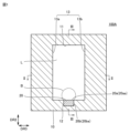
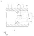
- FIG. 2 is a sectional view taken along line II-II in FIG. 1.
- FIG. 2 is a sectional view taken along III-III in FIG. 1.
- FIG. FIG. 2 is a cross-sectional view of a liquid flow generator 200.
- FIG. 3 is a cross-sectional view of a liquid flow generation device 100A according to modification 1.
- 6 is a sectional view taken along line VV in FIG. 5.
- FIG. 7 is a cross-sectional view of a liquid flow generating device 100A according to a second modification.
- FIG. 7 is a cross-sectional view of a liquid flow generation device 100A according to modification 3.
- FIG. 7 is a graph showing the relationship between the central position of the bubble generating section 20aa in the first direction and the speed of the liquid L flowing through the channel 11.
- FIG. 7 is a cross-sectional view of a liquid flow generating device 100A according to modification 4.
- FIG. 100A is a cross-sectional view of a liquid flow generation device 100A according to modification 5.
- FIG. 100A is a sectional view of a liquid flow generating device 100A according to modification 6.
- FIG. 100A is a cross-sectional view of a liquid flow generation device 100A according to Modification Example 7.
- FIG. 100A is a cross-sectional view of a liquid flow generation device 100A according to Modification 8.
- FIG. It is a sectional view of liquid flow generating device 100B. It is a sectional view of liquid flow generation device 100B concerning a modification.
- It is a sectional view of liquid flow generating device 100C. It is a sectional view of liquid flow generation device 100D.
- Embodiment 1 A liquid flow generation device according to Embodiment 1 will be described.
- the liquid flow generation device according to the first embodiment is referred to as a liquid flow generation device 100A.
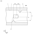
- FIG. 1 is a cross-sectional view of the liquid flow generator 100A.
- FIG. 1 shows a cross section of the liquid flow generator 100A orthogonal to the first direction DR1.
- FIG. 2 is a sectional view taken along line II-II in FIG.
- FIG. 3 is a sectional view taken along line III-III in FIG.
- the liquid flow generating device 100A includes a flow path structure 10 and a heating element 20.
- a flow path 11 is provided inside the flow path structure 10.
- the flow path 11 extends along the first direction DR1.
- a liquid L flows in the flow path 11 .
- the liquid L flows from one side (left side in FIG. 2) in the first direction DR1 toward the other side (right side in FIG. 2) in the first direction DR1.
- the liquid L may be, for example, water, alcohol, ammonia, oil, or a fluorocarbon-based refrigerant. However, the liquid L is not limited to these.
- a recess 12 is provided on the inner wall surface of the flow path 11.
- the inner wall surface of the flow path 11 is depressed in the recess 12 .
- the flow path structure 10 has a narrowed portion 13 .
- the flow path 11 is narrowed at a narrowed portion 13 . That is, in a cross section perpendicular to the first direction DR1, the cross-sectional area of the flow path 11 at the narrowed portion 13 is smaller than the cross-sectional area of the flow path 11 outside the narrowed portion 13.
- the cross-sectional area of the flow path 11 at the narrowed portion 13 is, for example, 0.8 times or less than the cross-sectional area of the flow path 11 outside the narrowed portion 13 .
- the normal direction of the first surface 20a which will be described later, is referred to as a second direction DR2.
- the second direction DR2 is orthogonal to the first direction DR1.
- a direction perpendicular to the first direction DR1 and the second direction DR2 is defined as a third direction DR3.
- the narrowed portion 13 has a first protrusion 13a and a second protrusion 13b.
- the first protrusion 13a and the second protrusion 13b protrude from the inner wall surface of the flow path 11 along the third direction DR3.
- the first protrusion 13a and the second protrusion 13b face each other with an interval in the third direction DR3.
- the width of the flow path 11 in the second direction DR2 is defined as a width W1.
- the width of the flow path 11 in the third direction DR3 is defined as a width W2.
- the width W1 is the distance between portions of the inner wall surface of the flow path 11 that are spaced apart and facing each other in the second direction DR2.
- the width W2 is the distance between inner wall surfaces of the flow path 11 facing each other with an interval in the third direction DR3. It is assumed that the width W1 and the width W2 are measured at a position other than the narrowed portion 13.
- the width W1 and the width W2 are, for example, 100 ⁇ m or less.
- Let the thickness of the channel structure 10 be the thickness T. It is assumed that the thickness T is measured at a position other than the narrowed portion 13.
- the thickness T is preferably 1000 ⁇ m or less from the viewpoint of reducing the thermal resistance of the flow path structure 10.
- the flow path structure 10 is made of a first material.
- the first material is preferably a material with excellent thermal conductivity.
- the first material is, for example, a metal material.
- Specific examples of the metal material include stainless steel, aluminum (Al), aluminum alloy, copper (Cu), copper alloy, and the like.
- the materials used for the channel structure 10 are not limited to these.
- the heating element 20 has a first surface 20a and a second surface 20b.
- the first surface 20a and the second surface 20b are end surfaces of the heating element 20 in the thickness direction.
- the second surface 20b is the opposite surface to the first surface 20a.
- the heating element 20 is arranged inside the channel structure 10 so that the first surface 20a is in contact with the liquid L flowing through the channel 11. More specifically, the heating element 20 is arranged inside the recess 12 so that the first surface 20a comes into contact with the liquid L flowing through the channel 11.
- the first surface 20a is preferably flush with the inner wall surface of the flow path 11.
- the first surface 20a has a bubble generating section 20aa and a high temperature section 20ab.
- the high temperature section 20ab is arranged on one side of the bubble generating section 20aa in the first direction DR1. To put this from another perspective, the high temperature section 20ab is adjacent to the bubble generating section 20aa from the upstream side in the flow direction of the liquid L flowing through the channel 11.
- the bubble generating portion 20aa is located at a position overlapping the narrowing portion 13 (first protrusion 13a, second protrusion 13b) in the first direction DR1.
- the second surface 20b has a heating part 20ba and a non-heating part 20bb.
- the heating section 20ba is located on the opposite side of the bubble generating section 20aa.
- Non-heated section 20bb is located on the opposite side of high temperature section 20ab. That is, the non-heating part 20bb is arranged on one side of the heating part 20ba in the first direction DR1.
- the heating part 20ba is heated by a heat source, but the non-heating part 20bb is not heated by a heat source. Therefore, the temperature in the high temperature section 20ab, which is located at a greater distance from the heating section 20ba, is lower than the temperature at the bubble generation section 20aa, which is located at a shorter distance from the heating section 20ba.
- the heating source is, for example, a laser beam.
- the heating source is not limited to laser light, and may be an electrode or the like.
- the heat source may be the semiconductor device.
- the amount of heating by the heating source is, for example, about 30 watts.
- the width of the heating element 20 in the third direction DR3 is defined as a width W3.
- the width W3 is, for example, 0.2 times or less of the width W1 and the width W2.
- the width W3 is preferably 0.1 times or less the widths W1 and W2.
- the heating element 20 is made of a second material.
- the second material is preferably a material with excellent thermal conductivity.
- the second material is, for example, a metal material.
- the second material has a higher thermal conductivity than the first material.
- specific examples of the second material include aluminum, aluminum alloy, copper, copper alloy, and the like.
- the heating section 20ba is heated by the heat source, and the temperature of the bubble generating section 20aa increases.
- bubbles B are generated in the liquid L that is in contact with the bubble generating section 20aa.
- a flow of the liquid L (indicated by an arrow in FIG. 2) from one side in the first direction DR1 to the other side in the first direction DR1 is generated due to the Marangoni effect.
- a shearing force called Marangoni force is generated due to the temperature gradient, and this shearing force causes A flow of liquid L occurs. Note that the temperature gradient described above occurs due to the distance from the high temperature section 20ab.
- the bubbles B tend to grow as the heating unit 20ba is heated by the heat source and the temperature of the bubble generating unit 20aa increases. However, if the bubbles B become too large, the temperature and pressure inside the bubbles B will decrease, causing the bubbles B to shrink. The flow of the liquid L also occurs due to repeated changes in the volume of the bubbles B. Note that as the heating by the heating source progresses, the temperature on the surface of bubble B increases and the Marangoni force increases, but the amount of liquid L carried near bubble B, that is, the cooling of the surface of bubble B by the flow of liquid L, becomes stronger. Therefore, the bubbles B do not separate from the bubble generation section 20aa, and the temperature gradient on the surface of the bubbles B and the size of the bubbles B are approximately constant on a time average basis.
- a liquid flow generation device according to a comparative example is referred to as a liquid flow generation device 200.
- FIG. 4 is a cross-sectional view of the liquid flow generating device 200.
- FIG. 4 shows a cross section of the liquid flow generating device 200 at a position corresponding to FIG. 2 .
- the liquid flow generating device 200 includes a flow path structure 10 and a heating element 20.
- the configuration of the liquid flow generation device 200 is common to the configuration of the liquid flow generation device 100A.
- the channel structure 10 does not have the narrowed portion 13.
- the configuration of the liquid flow generation device 200 is different from the configuration of the liquid flow generation device 100A.
- the liquid flow generation device 100A since the flow path structure 10 has the narrowed portion 13, the liquid flow passing through the narrowed portion 13 from one side in the first direction DR1 to the other side in the first direction DR1.
- the liquid L is less likely to return to the other side in the first direction DR1, and vortices are less likely to occur in the liquid L. Therefore, according to the liquid flow generation device 100A, it is possible to efficiently generate a unidirectional flow of the liquid L.
- a driving unit such as a diaphragm is not required, and there is no pulsation caused by driving the diaphragm or the like. According to the liquid flow generation device 100A, it is possible to efficiently generate a unidirectional flow of the liquid L from this viewpoint as well.
- the size of the bubble B is approximately the same as the width W3.
- the Marangoni force caused by the bubble B becomes smaller when the size of the bubble B becomes too large. Further, since a part of the flow path 11 is blocked by the air bubbles B, if the air bubbles B become too large, the flow path 11 cannot be widely used.
- the width W3 is 0.2 times or less than the widths W1 and W2
- the unidirectional flow of the liquid L can be made more efficient by ensuring the Marangoni force generated by the bubbles B and by making wide use of the flow path 11. This makes it possible to generate
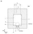
- FIG. 5 is a sectional view of a liquid flow generator 100A according to Modification 1.
- FIG. 5 shows a cross section of a liquid flow generating device 100A according to modification 1 at a position corresponding to FIG. 1.
- FIG. 6 is a sectional view taken along line VV in FIG.
- the narrowed portion 13 may further include a third protrusion 13c.
- the third protrusion 13c protrudes from the inner wall surface of the flow path 11 toward the heating element 20 along the second direction DR2.
- FIG. 7 is a sectional view of a liquid flow generating device 100A according to a second modification.
- FIG. 7 shows a cross section of a liquid flow generating device 100A according to modification 2 at a position corresponding to FIG. 2.
- FIG. 8 is a cross-sectional view of a liquid flow generating device 100A according to modification 3.
- FIG. 8 shows a cross section of a liquid flow generating device 100A according to modification 3 at a position corresponding to FIG. 2.
- the bubble generating section 20aa is located on one side of the narrowing section 13 in the first direction DR1.
- the bubble generating section 20aa is located on the other side of the narrowing section 13 in the first direction DR1.
- the distance between the narrowing part 13 and the bubble generating part 20aa in the first direction DR1 is defined as a distance DIS.
- the distance DIS is measured between the center of the narrowing portion 13 in the first direction DR1 and the center of the bubble generating portion 20aa in the first direction DR1.
- the distance DIS is preferably 0.4 times or less the width W2.
- it is further preferable that the distance DIS is 0.1 times or less the width W2.
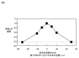
- FIG. 9 is a graph showing the relationship between the central position of the bubble generating section 20aa in the first direction and the speed of the liquid L flowing through the flow path 11.
- the horizontal axis in FIG. 9 is the center position of the bubble generating section 20aa in the first direction.
- the value on the horizontal axis is positive, it means that the center position of the bubble generating part 20aa in the first direction is on one side of the narrowing part 13 in the first direction DR1, and the value on the horizontal axis is positive.
- the vertical axis in FIG. 9 is the velocity of the liquid L, which is indicated by a magnification of the velocity of the liquid L when the value of the horizontal axis is 0.
- the graph shown in FIG. 9 was obtained by numerical analysis with the width W1 and the width W2 being 100 ⁇ m.
- the velocity of the liquid L in the case where the constriction part 13 is not provided is shown by a dotted line.
- the velocity of the liquid L was greater than the comparison value.
- the velocity of the liquid L was 0.8 times or more than when the value of the distance DIS was 0.
- FIG. 10 is a cross-sectional view of a liquid flow generating device 100A according to modification 4.
- FIG. 10 shows a cross section of a liquid flow generating device 100A according to modification 4 at a position corresponding to FIG. 2.
- the first protrusion 13a is located on one side in the first direction DR1 than the second protrusion 13b.
- FIG. 11 is a cross-sectional view of a liquid flow generation device 100A according to modification 5.
- FIG. 11 shows a cross section of a liquid flow generating device 100A according to modification 5 at a position corresponding to FIG. 2.
- the second protrusion 13b is located on one side in the first direction DR1 than the first protrusion 13a.
- the distance between the first protrusion 13a and the heat generating element 20 in the first direction DR1 is defined as a distance DIS1
- the distance between the second protrusion 13b and the heat generating element 20 in the first direction DR1 is defined as a distance DIS2.
- the distance DIS1 and the distance DIS2 are 0.1 times the width W2. According to the liquid flow generation device 100A according to the fourth modification and the liquid flow generation device 100A according to the fifth modification, even if the first protrusion 13a and the second protrusion 13b do not face each other, the liquid L can flow in one direction. can be generated efficiently.
- FIG. 12 is a cross-sectional view of a liquid flow generation device 100A according to modification 6.
- FIG. 12 shows a cross section of a liquid flow generating device 100A according to modification 6 at a position corresponding to FIG. 2.
- the tip of the first protrusion 13a is a flat surface in a cross-sectional view perpendicular to the second direction DR2, and the second protrusion The tip of 13b may be a flat surface.
- the first protrusion 13a and the second protrusion 13b have, for example, a trapezoidal shape in a cross-sectional view orthogonal to the second direction DR2.
- the tip of the first protrusion 13a and the tip of the second protrusion 13b are flat surfaces, so that the cross-sectional area of the flow path 11 in the narrowed portion 13 is reduced rapidly. Change is inhibited. Therefore, according to the liquid flow generating device 100A according to the sixth modification, the pressure loss caused by the liquid L passing through the constriction part 13 can be reduced.
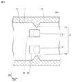
- FIG. 13 is a cross-sectional view of a liquid flow generation device 100A according to Modification Example 7.
- FIG. 13 shows a cross section of a liquid flow generating device 100A according to modification 8 at a position corresponding to FIG. 2.
- the number of heating elements 20 is plural.
- the plurality of heating elements 20 are lined up at intervals in the third direction DR3.
- FIG. 13 shows an example in which the number of heating elements 20 is two, in the liquid flow generation device 100A according to Modification Example 8, even if the number of heating elements 20 is three or more, good.
- the flow of the liquid L is generated by the plurality of bubbles B, so it is possible to increase the flow velocity of the liquid L. Note that when the distance between two adjacent bubbles B is small, vortices are less likely to occur between the two adjacent bubbles B.
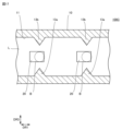
- FIG. 14 is a sectional view of a liquid flow generation device 100A according to Modification 8.
- FIG. 14 shows a cross section of a liquid flow generating device 100A according to modification 8 at a position corresponding to FIG. 2.
- the number of heating elements 20 is plural.
- the plurality of heating elements 20 are lined up at intervals in the third direction DR3.
- the narrowed portion 13 further includes a wedge portion 13d.
- the wedge portion 13d is arranged between two adjacent heating elements 20 in the third direction DR3.
- the interval between the first protrusion 13a and the second protrusion 13b is narrower than in the liquid flow generation device 100A according to the seventh modification, so that the flow velocity of the liquid L is reduced. It is possible to increase it further.
- FIG. 14 shows an example in which the number of heating elements 20 is two, in the liquid flow generation device 100A according to Modification 8, even if the number of heating elements 20 is three or more, good.
- Embodiment 2 A liquid flow generation device according to a second embodiment will be described.
- the liquid flow generation device according to the second embodiment is referred to as a liquid flow generation device 100B.
- the points different from the liquid flow generator 100A will be mainly explained, and duplicate explanations will not be repeated.
- FIG. 15 is a cross-sectional view of the liquid flow generator 100B.
- FIG. 15 shows a cross section of the liquid flow generating device 100B orthogonal to the second direction DR2.
- the liquid flow generating device 100B includes a flow path structure 10 and a heating element 20.
- a flow path 11 is provided in a flow path structure 10, and the flow path structure 10 has a narrowed portion 13.
- the configuration of the liquid flow generation device 100B is common to the configuration of the liquid flow generation device 100A.
- the flow path 11 includes a first flow path 11a, a connecting portion 11b, and a second flow path 11c.
- the second flow path 11c is connected in series to the first flow path 11a via the connecting portion 11b.
- the cross-sectional area of the first flow path 11a is smaller than the cross-sectional area of the second flow path 11c.
- the cross-sectional area of the connecting portion 11b becomes smaller from the second flow path 11c side toward the first flow path 11a side.
- the first flow path 11a is located on one side of the second flow path 11c in the first direction DR1.
- the narrowed portion 13 is configured by a connecting portion 11b. Regarding these points, the configuration of the liquid flow generation device 100B is common to the configuration of the liquid flow generation device 100A.
- the widths of the first flow path 11a, the connection portion 11b, and the second flow path 11c in the third direction DR3 are changed.
- the cross-sectional area of the passage 11c is changed.
- the widths of the first flow path 11a, the connecting portion 11b, and the second flow path 11c in the third direction DR3 may also be changed.
- the liquid flow generation device 100B since the bubble generation section 20aa is arranged at a position overlapping the connection section 11b (that is, the narrowed section 13) in the first direction DR1, the generation of vortices in the liquid L is suppressed, so that the liquid It is possible to efficiently generate a unidirectional flow of L. Furthermore, the liquid flow generating device 100B is effective when the cross-sectional area of the flow path 11 needs to be reduced in accordance with the size of a semiconductor device or the like to be cooled.
- FIG. 16 is a sectional view of a liquid flow generating device 100B according to a modification.
- FIG. 16 shows a cross section of a liquid flow generating device 100B according to a modified example at a position corresponding to FIG. 15.
- the first flow path 11a is arranged on the other side in the first direction DR1 than the second flow path 11c.
- the liquid flow generation device 100B according to the modified example can efficiently generate a unidirectional flow of the liquid L by suppressing the generation of vortices in the liquid L.
- the liquid flow generating device 100B according to the modified example is effective when the cross-sectional area of the flow path 11 needs to be increased in accordance with the size of a semiconductor device or the like to be cooled.
- Embodiment 3 A liquid flow generation device according to Embodiment 3 will be explained.
- the liquid flow generation device according to the third embodiment is referred to as a liquid flow generation device 100C.
- the points different from the liquid flow generator 100A will be mainly explained, and duplicate explanations will not be repeated.
- FIG. 17 is a cross-sectional view of the liquid flow generator 100C.
- FIG. 17 shows a cross section of the liquid flow generator 100C orthogonal to the second direction DR2.
- the liquid flow generating device 100C includes a flow path structure 10 and a heating element 20.
- a flow path 11 is provided in the flow path structure 10, and the flow path structure 10 has a narrowed portion 13.
- the configuration of the liquid flow generation device 100C is common to the configuration of the liquid flow generation device 100A.
- the number of constricted portions 13 is plural, and the number of heating elements 20 is plural.
- the plurality of narrowed portions 13 are lined up at intervals along the first direction DR1, and the plurality of heating elements 20 are lined up at intervals along the first direction DR1.
- the configuration of the liquid flow generation device 100C is different from the configuration of the liquid flow generation device 100A.
- the number of narrowed portions 13 and the number of heating elements 20 are two, but the number of narrowed portions 13 and the number of heating elements 20 may be three or more.
- the liquid flow generator 100C has a plurality of heating elements 20. Since bubbles B are generated in the bubble generation portions 20aa of each of the plurality of heating elements 20, the number of bubbles B generated inside the flow path 11 is also plural in the liquid flow generation device 100C. As a result, in the liquid flow generating device 100C, the pressure for flowing the liquid L is increased compared to the case where the number of heating elements 20 is one. Therefore, the liquid flow generating device 100C is effective when the flow path 11 is long and the pressure loss is large.
- Embodiment 4 A liquid flow generation device according to Embodiment 4 will be described.
- the liquid flow generation device according to the fourth embodiment is referred to as a liquid flow generation device 100D.
- the points different from the liquid flow generator 100A will be mainly explained, and duplicate explanations will not be repeated.
- FIG. 18 is a cross-sectional view of the liquid flow generator 100D.
- FIG. 18 shows a cross section of the liquid flow generating device 100D perpendicular to the second direction DR2.
- the liquid flow generating device 100D includes a flow path structure 10 and a heating element 20.
- a flow path 11 is provided in a flow path structure 10, and the flow path structure 10 has a narrowed portion 13.
- the configuration of the liquid flow generation device 100D is common to the configuration of the liquid flow generation device 100A.
- the flow path 11 has a plurality of parallel flow paths 11d connected in parallel.
- the number of constricted portions 13 is plural, and the number of heating elements 20 is plural.
- each of the plurality of narrowed portions 13 is arranged in each of the plurality of parallel channels 11d.
- the configuration of the liquid flow generation device 100D is different from the configuration of the liquid flow generation device 100A. Note that in the example shown in FIG. 18, the number of narrowed portions 13, the number of heating elements 20, and the number of parallel flow paths 11d are two; 11d may be three or more.
- each of the plurality of heating elements 20 is arranged in each of the plurality of parallel flow paths 11d.
- the flow rate of the liquid L is increased compared to the case where the number of heating elements 20 is one.
Landscapes
- Engineering & Computer Science (AREA)
- Mechanical Engineering (AREA)
- General Engineering & Computer Science (AREA)
- Structures Of Non-Positive Displacement Pumps (AREA)
- Particle Formation And Scattering Control In Inkjet Printers (AREA)
Priority Applications (2)
| Application Number | Priority Date | Filing Date | Title |
|---|---|---|---|
| JP2023541072A JP7459388B1 (ja) | 2022-05-20 | 2022-05-20 | 液流発生装置 |
| PCT/JP2022/021002 WO2023223556A1 (ja) | 2022-05-20 | 2022-05-20 | 液流発生装置 |
Applications Claiming Priority (1)
| Application Number | Priority Date | Filing Date | Title |
|---|---|---|---|
| PCT/JP2022/021002 WO2023223556A1 (ja) | 2022-05-20 | 2022-05-20 | 液流発生装置 |
Publications (1)
| Publication Number | Publication Date |
|---|---|
| WO2023223556A1 true WO2023223556A1 (ja) | 2023-11-23 |
Family
ID=88835032
Family Applications (1)
| Application Number | Title | Priority Date | Filing Date |
|---|---|---|---|
| PCT/JP2022/021002 Ceased WO2023223556A1 (ja) | 2022-05-20 | 2022-05-20 | 液流発生装置 |
Country Status (2)
| Country | Link |
|---|---|
| JP (1) | JP7459388B1 (https=) |
| WO (1) | WO2023223556A1 (https=) |
Citations (7)
| Publication number | Priority date | Publication date | Assignee | Title |
|---|---|---|---|---|
| JPS631773A (ja) * | 1986-06-23 | 1988-01-06 | Kenji Okayasu | 熱駆動ポンプ |
| JP2001062285A (ja) * | 1999-08-30 | 2001-03-13 | Japan Science & Technology Corp | 気泡搬送方法およびその装置 |
| JP2004098232A (ja) * | 2002-09-10 | 2004-04-02 | Canon Inc | 液体搬送装置 |
| JP2004218644A (ja) * | 2003-01-15 | 2004-08-05 | Samsung Electronics Co Ltd | 流体の相変化によって駆動されるマイクロポンプ |
| JP2008116381A (ja) * | 2006-11-07 | 2008-05-22 | Tokyo Univ Of Agriculture & Technology | マイクロポンプ |
| CN108725846A (zh) * | 2018-05-03 | 2018-11-02 | 北京工业大学 | 感应加热的液体蒸发型微推进器及其制备方法 |
| WO2021130934A1 (ja) * | 2019-12-25 | 2021-07-01 | 三菱電機株式会社 | 液流発生装置および熱交換器 |
-
2022
- 2022-05-20 JP JP2023541072A patent/JP7459388B1/ja active Active
- 2022-05-20 WO PCT/JP2022/021002 patent/WO2023223556A1/ja not_active Ceased
Patent Citations (7)
| Publication number | Priority date | Publication date | Assignee | Title |
|---|---|---|---|---|
| JPS631773A (ja) * | 1986-06-23 | 1988-01-06 | Kenji Okayasu | 熱駆動ポンプ |
| JP2001062285A (ja) * | 1999-08-30 | 2001-03-13 | Japan Science & Technology Corp | 気泡搬送方法およびその装置 |
| JP2004098232A (ja) * | 2002-09-10 | 2004-04-02 | Canon Inc | 液体搬送装置 |
| JP2004218644A (ja) * | 2003-01-15 | 2004-08-05 | Samsung Electronics Co Ltd | 流体の相変化によって駆動されるマイクロポンプ |
| JP2008116381A (ja) * | 2006-11-07 | 2008-05-22 | Tokyo Univ Of Agriculture & Technology | マイクロポンプ |
| CN108725846A (zh) * | 2018-05-03 | 2018-11-02 | 北京工业大学 | 感应加热的液体蒸发型微推进器及其制备方法 |
| WO2021130934A1 (ja) * | 2019-12-25 | 2021-07-01 | 三菱電機株式会社 | 液流発生装置および熱交換器 |
Also Published As
| Publication number | Publication date |
|---|---|
| JP7459388B1 (ja) | 2024-04-01 |
| JPWO2023223556A1 (https=) | 2023-11-23 |
Similar Documents
| Publication | Publication Date | Title |
|---|---|---|
| JP4907703B2 (ja) | マイクロチャネル熱交換器、熱源を冷却する方法 | |
| US12144147B2 (en) | Cooling apparatus for power module | |
| JP3857060B2 (ja) | 発熱体冷却装置 | |
| CN110637363A (zh) | 散热器和用于生产该散热器的方法 | |
| JP2005003355A (ja) | 乱れ発生部材 | |
| JP5539352B2 (ja) | チャンネルシステム | |
| JPWO2004076952A1 (ja) | ヒートシンク、レーザモジュール、レーザ装置及びレーザ加工装置 | |
| CN108886188A (zh) | 电池模块的调温装置、用于制造电池模块的方法以及电池模块 | |
| JPWO2014171095A1 (ja) | 熱交換器 | |
| WO2017002819A1 (ja) | 熱交換器のインナーフィン | |
| JP5498143B2 (ja) | 曲折ルーバー状放熱ユニットを用いたヒートシンク | |
| WO2023223556A1 (ja) | 液流発生装置 | |
| WO2020031753A1 (ja) | 冷却器、半導体モジュール | |
| CN116558330A (zh) | 热交换器 | |
| CN100544140C (zh) | 气体激光器振荡装置 | |
| JP7068574B2 (ja) | 伝熱管ユニットを有する熱交換器 | |
| CN119095332A (zh) | 一种射流冷板 | |
| KR102627492B1 (ko) | 전자 부품용 냉각 장치 | |
| JP2017044461A (ja) | 熱交換器 | |
| JP2019184129A (ja) | 熱交換器 | |
| JP7148118B2 (ja) | 伝熱装置 | |
| WO2020101628A1 (en) | Heat exchanger with movable blades | |
| WO2026038339A1 (ja) | 冷却装置 | |
| CN116847628B (en) | Jet flow micro-channel heat sink | |
| WO2026022919A1 (ja) | 冷却装置 |
Legal Events
| Date | Code | Title | Description |
|---|---|---|---|
| ENP | Entry into the national phase |
Ref document number: 2023541072 Country of ref document: JP Kind code of ref document: A |
|
| 121 | Ep: the epo has been informed by wipo that ep was designated in this application |
Ref document number: 22942760 Country of ref document: EP Kind code of ref document: A1 |
|
| NENP | Non-entry into the national phase |
Ref country code: DE |
|
| 122 | Ep: pct application non-entry in european phase |
Ref document number: 22942760 Country of ref document: EP Kind code of ref document: A1 |