WO2023223378A1 - Aerosol generating system and control method - Google Patents
Aerosol generating system and control method Download PDFInfo
- Publication number
- WO2023223378A1 WO2023223378A1 PCT/JP2022/020344 JP2022020344W WO2023223378A1 WO 2023223378 A1 WO2023223378 A1 WO 2023223378A1 JP 2022020344 W JP2022020344 W JP 2022020344W WO 2023223378 A1 WO2023223378 A1 WO 2023223378A1
- Authority
- WO
- WIPO (PCT)
- Prior art keywords
- temperature
- heating
- unit
- section
- difference
- Prior art date
Links
- 239000000443 aerosol Substances 0.000 title claims abstract description 94
- 238000000034 method Methods 0.000 title claims description 29
- 238000010438 heat treatment Methods 0.000 claims abstract description 412
- 230000008859 change Effects 0.000 claims abstract description 27
- 238000005070 sampling Methods 0.000 claims description 33
- 238000005259 measurement Methods 0.000 claims description 30
- 239000000463 material Substances 0.000 claims description 29
- 230000007704 transition Effects 0.000 claims description 15
- 230000007246 mechanism Effects 0.000 abstract description 5
- 230000006866 deterioration Effects 0.000 description 14
- 230000008569 process Effects 0.000 description 12
- 238000012545 processing Methods 0.000 description 9
- 238000004891 communication Methods 0.000 description 8
- 239000000796 flavoring agent Substances 0.000 description 7
- 235000019634 flavors Nutrition 0.000 description 7
- 238000010586 diagram Methods 0.000 description 5
- 230000007423 decrease Effects 0.000 description 4
- 230000006870 function Effects 0.000 description 4
- 230000000391 smoking effect Effects 0.000 description 4
- 239000000126 substance Substances 0.000 description 4
- DNIAPMSPPWPWGF-UHFFFAOYSA-N Propylene glycol Chemical compound CC(O)CO DNIAPMSPPWPWGF-UHFFFAOYSA-N 0.000 description 3
- 238000004364 calculation method Methods 0.000 description 3
- 230000005674 electromagnetic induction Effects 0.000 description 3
- PEDCQBHIVMGVHV-UHFFFAOYSA-N Glycerine Chemical compound OCC(O)CO PEDCQBHIVMGVHV-UHFFFAOYSA-N 0.000 description 2
- 241000208125 Nicotiana Species 0.000 description 2
- 235000002637 Nicotiana tabacum Nutrition 0.000 description 2
- 230000009471 action Effects 0.000 description 2
- 230000002542 deteriorative effect Effects 0.000 description 2
- 230000006698 induction Effects 0.000 description 2
- 239000011810 insulating material Substances 0.000 description 2
- 239000007788 liquid Substances 0.000 description 2
- BASFCYQUMIYNBI-UHFFFAOYSA-N platinum Chemical compound [Pt] BASFCYQUMIYNBI-UHFFFAOYSA-N 0.000 description 2
- 230000001007 puffing effect Effects 0.000 description 2
- 239000000779 smoke Substances 0.000 description 2
- 239000000758 substrate Substances 0.000 description 2
- 238000012546 transfer Methods 0.000 description 2
- XLYOFNOQVPJJNP-UHFFFAOYSA-N water Substances O XLYOFNOQVPJJNP-UHFFFAOYSA-N 0.000 description 2
- HBBGRARXTFLTSG-UHFFFAOYSA-N Lithium ion Chemical compound [Li+] HBBGRARXTFLTSG-UHFFFAOYSA-N 0.000 description 1
- 241000555745 Sciuridae Species 0.000 description 1
- 238000010521 absorption reaction Methods 0.000 description 1
- 238000013459 approach Methods 0.000 description 1
- 238000004590 computer program Methods 0.000 description 1
- 230000003247 decreasing effect Effects 0.000 description 1
- 239000003814 drug Substances 0.000 description 1
- 229940079593 drug Drugs 0.000 description 1
- 230000005611 electricity Effects 0.000 description 1
- 239000003571 electronic cigarette Substances 0.000 description 1
- 238000005516 engineering process Methods 0.000 description 1
- 235000011187 glycerol Nutrition 0.000 description 1
- 230000006872 improvement Effects 0.000 description 1
- 229910001416 lithium ion Inorganic materials 0.000 description 1
- 238000012986 modification Methods 0.000 description 1
- 230000004048 modification Effects 0.000 description 1
- 239000006199 nebulizer Substances 0.000 description 1
- 230000003287 optical effect Effects 0.000 description 1
- 229910052697 platinum Inorganic materials 0.000 description 1
- 230000009993 protective function Effects 0.000 description 1
- 239000007787 solid Substances 0.000 description 1
- 150000005846 sugar alcohols Polymers 0.000 description 1
- 239000013589 supplement Substances 0.000 description 1
Images


Classifications
-
- A—HUMAN NECESSITIES
- A24—TOBACCO; CIGARS; CIGARETTES; SIMULATED SMOKING DEVICES; SMOKERS' REQUISITES
- A24F—SMOKERS' REQUISITES; MATCH BOXES; SIMULATED SMOKING DEVICES
- A24F40/00—Electrically operated smoking devices; Component parts thereof; Manufacture thereof; Maintenance or testing thereof; Charging means specially adapted therefor
- A24F40/50—Control or monitoring
- A24F40/57—Temperature control
Definitions
- the present disclosure relates to an aerosol generation system and a control method.
- a suction device generates an aerosol to which a flavor component has been added using a base material that includes an aerosol source for generating an aerosol, a flavor source for imparting a flavor component to the generated aerosol, and the like.
- the user can enjoy the taste of smoking by inhaling the aerosol to which the flavor component is added, which is generated by the suction device.
- the action of the user inhaling an aerosol will also be referred to below as a puff or a puff action.
- Patent Document 1 listed below discloses that a component whose resistance changes with respect to temperature change is provided and used to control the temperature of the heated portion.
- the present disclosure has been made in view of the above problems, and the purpose of the present disclosure is to provide a mechanism that can further improve the quality of user experience.
- a power supply section a heating section that heats an aerosol source using electric power supplied from the power supply section, and a heating section that follows temperature changes of the heating section.
- a temperature changing part whose temperature changes by changing the temperature, a first measured value measured as a parameter corresponding to the temperature of the heating part, and a second measured value measured as a parameter corresponding to the temperature of the temperature changing part.
- An aerosol generation system comprising: a control section that controls the operation of the heating section based on the difference between the temperature of the heating section and the temperature of the temperature changing section.
- the control unit may switch a parameter used as a basis for controlling power supply to the heating unit based on a difference between the temperature of the heating unit and the temperature of the temperature changing unit.
- the control unit determines a parameter based on which the power supply to the heating unit is restarted after temporarily stopping the power supply to the heating unit, based on the difference between the temperature of the heating unit and the temperature of the temperature changing unit. You can also switch by
- the control unit may restart power supply to the heating unit based on the second measured value when the difference between the temperature of the heating unit and the temperature of the temperature changing unit is within a first range. good.
- the control section controls the elapsed time. Based on this, the power supply to the heating section may be restarted.
- the control unit stops power supply to the heating unit or prohibits power supply to the heating unit when the difference between the temperature of the heating unit and the temperature of the temperature change unit exceeds the second range. You may perform at least one of the following.
- the control unit determines the first range and the second range based on the difference between the temperature of the heating unit and the temperature of the temperature changing unit, which are obtained when heating by the heating unit is performed for the first time. may be set.
- the aerosol generation system includes a storage unit that stores information, and the control unit controls the operation of the heating unit based on control information that defines a time series transition of a target temperature for heating the aerosol source. , acquiring a difference between the temperature of the heating section and the temperature of the temperature changing section during a sampling period that is a part of a period in which the time-series transition of the target value is defined by the control information, and storing it in the storage section.
- the operation of the heating section may be controlled based on a difference between the temperature of the heating section and the temperature of the temperature changing section stored in the storage section.
- the control unit acquires the difference between the temperature of the heating unit and the temperature of the temperature changing unit multiple times during the sampling period, and calculates a statistical value of the difference between the temperature of the plurality of heating units and the temperature of the temperature changing unit.
- the period in which the time-series transition of the target value is defined by the control information includes a period in which the temperature of the heating section is temporarily lowered, and the control section is configured to
- the sampling period may be a period after a period in which power supply to the heating section is stopped and the temperature of the heating section is lowered.
- the control unit may set the sampling period based on the first measurement value when starting heating by the heating unit based on the control information.
- the control unit sets the timing to start the sampling period earlier, as the temperature of the heating unit indicated by the first measurement value when starting heating by the heating unit based on the control information is higher. It's okay.
- the heating section is a resistance heating element that generates heat when a current is applied
- the first measurement value is an electrical resistance value of the resistance heating element
- the temperature changing section changes electricity according to temperature changes.
- the resistor may be a resistor whose resistance value changes
- the second measurement value may be an electrical resistance value of the resistor.
- the aerosol generation system may further include a base material containing the aerosol source.
- a control method for controlling an aerosol generation system wherein the aerosol generation system includes a power supply unit and a power supply unit that is supplied from the power supply unit. a heating section that heats the aerosol source using the electric power generated by the heating section; and a temperature changing section that changes the temperature in accordance with the temperature change of the heating section, and the control method includes: The difference between the temperature of the heating part and the temperature of the temperature changing part, which is indicated by a first measured value measured as a value corresponding to the temperature of the temperature changing part and a second measured value measured as a value corresponding to the temperature of the temperature changing part. Based on the invention, a control method is provided, including controlling an operation of the heating section.
- FIG. 2 is a schematic diagram schematically showing a configuration example of a suction device.
- 2 is a graph showing an example of a change in temperature of a heating section when temperature control is performed based on the heating profile shown in Table 1.
- FIG. 3 is a diagram for explaining an example of control details of the operation of the heating unit according to the present embodiment. It is a flowchart which shows an example of the flow of processing performed by the suction device concerning this embodiment.
- a suction device is a device that produces a substance that is inhaled by a user.
- the substance generated by the suction device is an aerosol.
- the substance produced by the suction device may be a gas.
- FIG. 1 is a schematic diagram schematically showing a configuration example of a suction device.
- the suction device 100 according to the present configuration example includes a power supply section 111, a sensor section 112, a notification section 113, a storage section 114, a communication section 115, a control section 116, a heating section 121, a holding section 140, and A heat insulating section 144 is included.
- the power supply unit 111 stores power. Then, the power supply unit 111 supplies power to each component of the suction device 100 based on control by the control unit 116.
- the power supply unit 111 may be configured with a rechargeable battery such as a lithium ion secondary battery, for example.
- the sensor unit 112 acquires various information regarding the suction device 100.
- the sensor unit 112 includes a pressure sensor such as a condenser microphone, a flow rate sensor, a temperature sensor, etc., and acquires a value associated with suction by the user.
- the sensor unit 112 is configured with an input device such as a button or a switch that receives information input from the user.
- the sensor section 112 includes a thermistor 117 for detecting the temperature of the heating section 121 from outside the heating section 121.
- the thermistor 117 is an example of a temperature changing section whose temperature changes following the temperature change of the heating section 121.
- the thermistor 117 is disposed near the heating section 121, such as in close contact with the heating section 121, and its temperature changes due to heat transfer from the heating section 121.
- the temperature of the thermistor 117 is then detected as the temperature of the heating section 121.
- Thermistor 117 includes a resistor whose electrical resistance value changes according to temperature changes. Then, the temperature of the thermistor 117 is calculated based on the electrical resistance value of the resistor.
- the thermistor 117 may be configured as, for example, a negative temperature coefficient (NTC) thermistor, a positive temperature coefficient (PTC) thermistor, or a critical temperature resistor (CTR) thermistor.
- NTC negative temperature coefficient
- PTC positive temperature coefficient
- CTR critical temperature resistor
- a temperature measuring resistor made of platinum or the like may be used as the temperature change section.
- a resistance temperature detector may also be referred to as an RTD (Resistance Temperature Detector).
- the notification unit 113 notifies the user of information.
- the notification unit 113 includes, for example, a light emitting device that emits light, a display device that displays an image, a sound output device that outputs sound, a vibration device that vibrates, or the like.
- the storage unit 114 stores various information for the operation of the suction device 100.
- the storage unit 114 is configured by, for example, a nonvolatile storage medium such as a flash memory.
- the communication unit 115 is a communication interface that can perform communication compliant with any wired or wireless communication standard.
- a communication standard for example, a standard using Wi-Fi (registered trademark), Bluetooth (registered trademark), or LPWA (Low Power Wide Area) may be adopted.
- the control unit 116 functions as an arithmetic processing device and a control device, and controls overall operations within the suction device 100 according to various programs.
- the control unit 116 is realized by, for example, an electronic circuit such as a CPU (Central Processing Unit) and a microprocessor.
- the holding part 140 has an internal space 141 and holds the stick-type base material 150 while accommodating a part of the stick-type base material 150 in the internal space 141.
- the holding part 140 has an opening 142 that communicates the internal space 141 with the outside, and holds the stick-shaped base material 150 inserted into the internal space 141 through the opening 142.
- the holding part 140 is a cylindrical body having an opening 142 and a bottom part 143 as the bottom surface, and defines a columnar internal space 141.
- An air flow path that supplies air to the internal space 141 is connected to the holding portion 140 .
- An air inflow hole which is an inlet of air to the air flow path, is arranged on a side surface of the suction device 100, for example.
- An air outlet hole which is an outlet for air from the air flow path to the internal space 141, is arranged at the bottom 143, for example.
- the stick-type base material 150 includes a base portion 151 and a mouthpiece portion 152.
- Base portion 151 includes an aerosol source.
- Aerosol sources are, for example, polyhydric alcohols such as glycerin and propylene glycol, and liquids such as water.
- the aerosol source may include flavor components of tobacco or non-tobacco origin. If the suction device 100 is a medical inhaler, such as a nebulizer, the aerosol source may include a drug. Note that in this configuration example, the aerosol source is not limited to a liquid, and may be a solid.
- the heating unit 121 atomizes the aerosol source to generate aerosol by heating the aerosol source.
- the heating unit 121 uses the power supplied from the power supply unit 111 to heat the aerosol source.
- the heating section 121 is configured as a resistance heating element that generates heat due to electrical resistance when a current is applied.
- the heating section 121 is formed into a film shape and is arranged to cover the outer periphery of the holding section 140.
- the heating part 121 generates heat
- the base material part 151 of the stick-type base material 150 is heated from the outer periphery, and an aerosol is generated.
- the heating unit 121 generates heat when supplied with power from the power supply unit 111 .
- power may be supplied when the sensor unit 112 detects that the user has started suctioning and/or that predetermined information has been input. Then, when the sensor unit 112 detects that the user has finished suctioning and/or that predetermined information has been input, the power supply may be stopped.
- the heat insulating section 144 prevents heat transfer from the heating section 121 to other components.
- the heat insulating section 144 is made of a vacuum heat insulating material, an airgel heat insulating material, or the like.
- suction device 100 has been described above.
- the configuration of the suction device 100 is not limited to the above, and may take various configurations as exemplified below.
- the heating unit 121 may be configured in a blade shape and arranged to protrude from the bottom 143 of the holding unit 140 into the internal space 141. In that case, the blade-shaped heating unit 121 is inserted into the base portion 151 of the stick-type base material 150 and heats the base portion 151 of the stick-type base material 150 from inside.
- the heating part 121 may be arranged to cover the bottom part 143 of the holding part 140.
- the heating section 121 is a combination of two or more of a first heating section that covers the outer periphery of the holding section 140 , a second heating section shaped like a blade, and a third heating section that covers the bottom 143 of the holding section 140 . It may be configured as
- the holding part 140 may include an opening/closing mechanism such as a hinge that opens and closes a part of the outer shell that forms the internal space 141.
- the holding part 140 may hold the stick-shaped base material 150 inserted into the internal space 141 by opening and closing the outer shell.
- the heating unit 121 may be provided at the relevant clamping location in the holding unit 140 and may heat the stick-shaped base material 150 while pressing it.
- the stick-type base material 150 is an example of a base material that contains an aerosol source and contributes to the generation of aerosol.
- the suction device 100 is an example of an aerosol generation device that generates an aerosol by heating a stick-type base material 150.
- the combination of the suction device 100 and the stick-type base material 150 generates an aerosol. Therefore, the combination of the suction device 100 and the stick-type base material 150 may be regarded as an aerosol generation system.
- the heating profile is control information for controlling the temperature at which the aerosol source is heated.
- the heating profile may be control information for controlling the temperature of the heating section 121.
- the heating profile may include a target value for the temperature at which the aerosol source is heated (hereinafter also referred to as target temperature).
- target temperature may change according to the elapsed time from the start of heating, and in that case, the heating profile includes information that defines the time series transition of the target temperature.
- the heating profile may include parameters (hereinafter also referred to as power supply parameters) that define a method of supplying power to the heating unit 121.
- the power supply parameters include, for example, the voltage applied to the heating unit 121, ON/OFF of power supply to the heating unit 121, the feedback control method to be adopted, and the like. Turning on/off the power supply to the heating unit 121 may be regarded as turning the heating unit 121 on/off.
- the control unit 116 controls the operation of the heating unit 121 so that the temperature of the heating unit 121 (hereinafter also referred to as actual temperature) changes in the same manner as the target temperature defined in the heating profile.
- the heating profile is typically designed to optimize the flavor experienced by the user when the user inhales the aerosol generated from the stick-shaped substrate 150. Therefore, by controlling the operation of the heating unit 121 based on the heating profile, the flavor that the user enjoys can be optimized.
- Temperature control of the heating section 121 can be realized, for example, by known feedback control.
- the feedback control may be, for example, PID control (Proportional-Integral-Differential Controller).
- the control unit 116 can cause the power from the power supply unit 111 to be supplied to the heating unit 121 in the form of pulses using pulse width modulation (PWM) or pulse frequency modulation (PFM). In that case, the control unit 116 can control the temperature of the heating unit 121 by adjusting the duty ratio or frequency of the power pulse in feedback control. Alternatively, the control unit 116 may perform simple on/off control in feedback control.
- control unit 116 causes the heating unit 121 to perform heating until the actual temperature reaches the target temperature, and when the actual temperature reaches the target temperature, interrupts the heating by the heating unit 121 so that the actual temperature is lower than the target temperature. When the temperature becomes low, heating by the heating unit 121 may be restarted.
- the temperature of the heating section 121 can be quantified by measuring or estimating the electrical resistance value of the heating section 121 (more precisely, the resistance heating element that constitutes the heating section 121). This is because the electrical resistance value of the resistance heating element changes depending on the temperature.
- the electrical resistance value of the resistance heating element can be estimated, for example, by measuring the amount of voltage drop across the resistance heating element.
- the amount of voltage drop across the resistive heating element can be measured by a voltage sensor that measures the potential difference applied to the resistive heating element.
- the electrical resistance value of the resistance heating element constituting the heating section 121 is an example of a first measured value measured as a value corresponding to the temperature of the heating section 121.
- the temperature of the heating unit 121 calculated based on the first measured value is hereinafter also referred to as heater temperature.
- the temperature of the heating section 121 can be quantified by measuring or estimating the electrical resistance value of the thermistor 117 (more precisely, the resistor that constitutes the thermistor 117). This is because the temperature of the thermistor 117 changes depending on the temperature change of the heating section 121, and the electric resistance value of the resistor forming the thermistor 117 changes depending on the temperature.
- the electrical resistance value of the resistor can be estimated, for example, by measuring the amount of voltage drop across the resistor. The amount of voltage drop across the resistor can be measured by a voltage sensor that measures the potential difference applied to the resistor.
- the electrical resistance value of the resistor constituting the thermistor 117 is an example of a second measurement value that is measured as a value corresponding to the temperature of the thermistor 117.
- the temperature of the thermistor 117 calculated based on the second measurement value will also be referred to below as the thermistor temperature.
- a heating session is a period during which the operation of the heating section 121 is controlled based on the heating profile.
- the beginning of a heating session is the timing at which heating based on the heating profile is started.
- the end of the heating session is when a sufficient amount of aerosol is no longer generated.
- the heating session includes a preheating period and a puffable period following the preheating period.
- the puffable period is a period during which a sufficient amount of aerosol is expected to be generated.
- the preheating period is the period from when heating starts until the puffable period starts.
- the heating performed during the preheating period is also referred to as preheating.
- the heating profile may be divided into a plurality of periods, and a time-series transition of the target temperature and a time-series transition of the power supply parameters may be defined in each period.
- the heating profile is divided into a total of eight periods, STEP0 to STEP7.
- STEP a time-series transition of the target temperature and a time-series transition of the power supply parameter are defined.
- STEP defined in the heating profile is an example of a unit period in this embodiment.
- Time control may be implemented in each STEP.
- Time control is control that terminates a STEP using the passage of a predetermined time (that is, the duration set for each STEP) as a trigger.
- a predetermined time that is, the duration set for each STEP
- the rate of change in the temperature of the heating unit 121 may be controlled so that the temperature of the heating unit 121 reaches the target temperature at the end of the duration.
- heating is performed such that the temperature of the heating unit 121 reaches the target temperature in the middle of the duration time and then maintains the temperature of the heating unit 121 at the target temperature until the duration time elapses.
- the temperature of section 121 may be controlled. In the example shown in Table 1 above, time control is performed in STEP 1 and STEP 4 to 7.
- Time control may not be implemented in each STEP. If time control is not implemented, the STEP ends with the temperature of the heating section 121 reaching a predetermined temperature (that is, the target temperature set for each STEP) as a trigger. Therefore, the duration of STEP in which time control is not performed expands or contracts depending on the rate of temperature change. In the example shown in Table 1 above, time control is not performed in STEP 0, 2, and 3.
- FIG. 2 is a graph showing an example of a change in temperature of the heating section 121 when temperature control is performed based on the heating profile shown in Table 1.
- the horizontal axis of the graph 20 is time (seconds).
- the vertical axis of the graph 20 is the temperature of the heating section 121.
- a line 21 indicates the change in temperature of the heating section 121.
- the temperature of the heating section 121 changes in the same way as the target temperature defined in the heating profile.
- An example of a heating profile will be described below with reference to Table 1 and FIG. 2.
- the temperature of the heating section 121 rises from the initial temperature to 300°C.
- the initial temperature is the temperature of the heating section 121 at the start of heating.
- time control is not performed. Therefore, STEP0 ends when the temperature of the heating section 121 reaches 300° C. as a trigger. In the example shown in FIG. 2, STEP0 ends in 20 seconds.
- the temperature of the heating section 121 is maintained at 300°C.
- the preheating period ends with the end of STEP 1, and the puffable period begins with the start of STEP 2.
- the temperature of the heating section 121 be rapidly raised to 300° C. in STEP 0, and that the duration of STEP 1 be secured to some extent.
- the temperature of the heating section 121 decreases to 220°C.
- time control is not performed. Therefore, STEP 2 is terminated when the temperature of the heating section 121 reaches 220° C. as a trigger. In the example shown in FIG. 2, STEP 2 ends in 10 seconds.
- the power supply to the heating section 121 is turned off. Therefore, it is possible to reduce the temperature of the heating section 121 at the fastest speed. In this way, by lowering the temperature of the heating section 121 in the middle of a heating session, rapid consumption of the aerosol source can be prevented. As a result, it is possible to prevent depletion of the aerosol source during the heating session.
- STEP 3 the temperature of the heating section 121 rises to 230°C.
- time control is not performed. Therefore, STEP 3 is terminated when the temperature of the heating section 121 reaches 230° C. as a trigger.
- STEP3 ends in 5 seconds. In this way, by providing a period in which the temperature of the heating section 121 is lowered and then raised again, it is possible to prevent the temperature of the heating section 121 from excessively decreasing.
- the temperature of the heating section 121 increases stepwise to 260°C. In this way, by gradually increasing the temperature of the heating section 121, it is possible to maintain the amount of aerosol generated and to suppress power consumption during the entire heating session.
- the temperature of the heating section 121 decreases.
- the power supply to the heating section 121 is turned off.
- the duration is defined, the target temperature is not defined. Therefore, STEP7 ends using the end of the duration as a trigger.
- a sufficient amount of aerosol can be generated by the residual heat of the stick-type base material 150. Therefore, in this example, the puffable period, that is, the heating session ends at the end of STEP7.
- the notification unit 113 may notify the user of information indicating the timing at which preheating ends. For example, the notification unit 113 may notify information that foretells the end of preheating before the end of preheating, or may notify information indicating that preheating has ended at the timing when preheating has ended. The user may be notified by, for example, lighting an LED or vibrating. The user can refer to this notification and start puffing immediately after the end of preheating.
- the notification unit 113 may notify the user of information indicating the timing at which the puffable period ends. For example, the notification unit 113 may notify information foretelling the end of the puffable period before the puffable period ends, or notify information indicating that the puffable period has ended at the timing when the puffable period has ended. or The user may be notified by, for example, lighting an LED or vibrating. The user is able to puff until the puffing period ends with reference to this notification.
- the heating profile described above is just an example, and various other examples are possible.
- the number of STEPs, the duration of each STEP, and the target temperature may be changed as appropriate.
- the control unit 116 can control the operation of the heating unit 121 by comparing the heater temperature with the target temperature.
- the control unit 116 can control the operation of the heating unit 121 by comparing the thermistor temperature and the target temperature.
- the measurement accuracy of the electrical resistance value of the thermistor 117 may deteriorate.
- One example of the cause is deterioration of the thermistor 117 over time. In that case, it becomes difficult to appropriately control the operation of the heating section 121 during a period in which the operation of the heating section 121 is controlled based on the thermistor temperature as in STEP2.
- the thermistor temperature can be used for a protective function such as stopping heating by the heating unit 121 when thermal runaway, which is a phenomenon in which the temperature of the heating unit 121 rises excessively, occurs. If the measurement accuracy of the electrical resistance value of the thermistor 117 deteriorates, it may become difficult to properly apply the protection function. In this manner, deterioration in the measurement accuracy of the electrical resistance value of the thermistor 117 may cause deterioration in the quality of the user experience.
- a mechanism is provided to prevent the quality of the user experience from deteriorating due to the deterioration of the measurement accuracy of the electrical resistance value of the thermistor 117.
- Operation control of heating section 121> (1) Control based on the difference between heater temperature and thermistor temperature
- the control unit 116 performs heating based on the difference between the heater temperature and thermistor temperature indicated by the electrical resistance value of the heating section 121 and the electrical resistance value of the thermistor 117.
- the operation of the unit 121 is controlled. Specifically, first, the control unit 116 calculates the heater temperature based on the electrical resistance value of the heating unit 121 and calculates the thermistor temperature based on the electrical resistance value of the thermistor 117. Next, the control unit 116 determines deterioration in the measurement accuracy of the electrical resistance value of the thermistor 117 based on the difference between the heater temperature and the thermistor temperature.
- control unit 116 controls the operation of the heating unit 121 according to the degree of deterioration in the measurement accuracy of the electrical resistance value of the thermistor 117. According to this configuration, it is possible to prevent the quality of the user experience from deteriorating due to deterioration in the accuracy of measuring the electrical resistance value of the thermistor 117.
- the control unit 116 may switch the parameter used as the basis for controlling the power supply to the heating unit 121 based on the difference between the heater temperature and the thermistor temperature. According to this configuration, it is possible to control the operation of the heating section 121 based on appropriate parameters.
- the control unit 116 switches the parameter used as the basis for restarting the power supply to the heating unit 121 after temporarily stopping the power supply to the heating unit 121, based on the difference between the heater temperature and the thermistor temperature. Good too.
- the heating session includes a period during which the temperature of the heating unit 121 is temporarily lowered, as in STEP 2. Then, the control unit 116 stops power supply to the heating unit 121 during a period in which the temperature of the heating unit 121 is temporarily lowered. After that, the control unit 116 restarts power supply to the heating unit 121.
- control unit 116 restarts power supply to the heating unit 121 at a timing based on a parameter selected based on the difference between the heater temperature and the thermistor temperature. According to this configuration, it becomes possible to appropriately control the temperature drop of the heating section 121.
- FIG. 3 is a diagram for explaining an example of the control content of the operation of the heating section 121 according to the present embodiment.
- the vertical axis represents the difference between the heater temperature and the thermistor temperature
- the control contents according to the difference between the heater temperature and the thermistor temperature are written along the vertical axis.
- the control unit 116 may restart power supply to the heating unit 121 based on the thermistor temperature.
- the first range is set as a range in which the heater temperature and the thermistor temperature may be considered to be the same if the difference between the heater temperature and the thermistor temperature is included in the first range.
- the first range is a range of ⁇ 3°C.
- the control unit 116 uses the thermistor temperature as a trigger to decrease to the target temperature at the end of STEP 2 specified in the heating profile, and controls the heating unit Restart power supply to 121. According to this configuration, even during a period where it is difficult to obtain the heater temperature as in STEP 2, by referring to the thermistor temperature instead, it is possible to make the temperature of the heating section 121 change as specified in the heating profile. Become.
- the control unit 116 controls the difference based on the elapsed time.
- the power supply to the heating unit 121 may be restarted.
- the second range is set as a range in which it is assumed that problems such as thermal runaway will not occur if the difference between the heater temperature and the thermistor temperature is included in the second range.
- the second range is a range of ⁇ 10°C.
- the control unit 116 triggers the heating unit 121 when a predetermined time has elapsed since STEP 2 was started. Resume power supply to.
- the predetermined time can be defined in the heating profile. Alternatively, the predetermined time may be calculated based on the range of decrease in the target temperature in STEP2. According to this configuration, even if there is an error between the heater temperature and the thermistor temperature and it is difficult to control based on the thermistor temperature, the heating section can be adjusted within a range that does not significantly deviate from the target temperature specified in the heating profile. It becomes possible to change the temperature of 121.
- the control unit 116 prohibits power supply to the heating unit 121 or stops power supply to the heating unit 121.
- Stopping the power supply to the heating unit 121 is a concept that refers to stopping the power supply to the heating unit 121 during execution.
- Prohibiting power supply to heating unit 121 is a concept that includes not executing power supply to heating unit 121 in addition to stopping power supply to heating unit 121 . According to this configuration, even if the protection function does not work well due to deterioration in the measurement accuracy of the electrical resistance value of the thermistor 117, it is possible to prevent problems such as thermal runaway from occurring.
- the control unit 116 acquires the difference between the heater temperature and the thermistor temperature during a sampling period, which is a part of the heating session, and stores it in the storage unit 114. It's okay. Then, the control unit 116 may control the operation of the heating unit 121 based on the difference between the heater temperature and the thermistor temperature stored in the storage unit 114. Typically, the control unit 116 uses the difference between the heater temperature and thermistor temperature acquired in a certain heating session to control the operation of the heating unit 121 in the next heating session and thereafter.
- control unit 116 acquires the difference between the heater temperature and the thermistor temperature by setting a sampling period once in a plurality of heating sessions, and calculates the difference between the acquired heater temperature and thermistor temperature in subsequent heating sessions. It may also be used in According to this configuration, it is possible to reduce the processing load on the suction device 100. Of course, the difference between the heater temperature and thermistor temperature obtained in a certain heating session may be used to control the operation of the heating unit 121 in the same heating session.
- the control unit 116 may obtain the difference between the heater temperature and the thermistor temperature multiple times during the sampling period, and store the statistical values of the differences between the multiple heater temperatures and the thermistor temperature in the storage unit 114.
- the control unit 116 may control the operation of the heating unit 121 based on the statistical value of the difference between the heater temperature and the thermistor temperature stored in the storage unit 114.
- Statistics can be calculated by various statistical techniques, such as an average, a weighted average, or a median. According to this configuration, it becomes possible to more accurately determine the deterioration in the measurement accuracy of the electrical resistance value of the thermistor 117.
- the sampling period be a period after the period in which the temperature of the heating section 121 is temporarily lowered.
- the sampling period is preferably the period after STEP 3.
- the heater temperature is rapidly increasing or has just risen rapidly, so a large difference naturally occurs between the heater temperature and the thermistor temperature. This is because the thermistor temperature follows the heater temperature but increases with a delay. That is, the difference between the heater temperature and the thermistor temperature in STEP 0 and STEP 1 is the sum of the value caused by the deterioration in measurement accuracy of the electrical resistance value of the thermistor 117 and the value caused by the delay in the temperature rise of the thermistor temperature. .
- the thermistor temperature is considered to have risen sufficiently until it asymptotically approaches the heater temperature. That is, the difference between the heater temperature and the thermistor temperature after STEP 3 does not include the value caused by the delay in the temperature rise of the thermistor temperature, but only includes the value caused by the deterioration in the measurement accuracy of the electrical resistance value of the thermistor 117. It seems to be converging. Therefore, with this configuration, it is possible to more accurately determine the deterioration in the measurement accuracy of the electrical resistance value of the thermistor 117.
- so-called chain smoking may be performed, in which the stick-shaped base material 150 is heated multiple times while being replaced at short intervals.
- the initial temperature of the heating unit 121 during the second and subsequent heating is higher than the initial temperature of the heating unit 121 during the first heating. The higher the initial temperature, the earlier the timing at which the difference between the heater temperature and thermistor temperature converges.
- the control unit 116 may set the sampling period based on the initial temperature of the heating unit 121. In particular, the control unit 116 may set the timing to start the sampling period earlier as the initial temperature of the heating unit 121 is higher.
- the initial temperature of the heating section 121 the heater temperature at the time of starting heating, that is, when the heating section 121 starts heating based on the heating profile may be used. For example, if the heater temperature at the start of heating is less than a predetermined threshold, the control unit 116 may set STEP 5 and STEP 6 as the sampling period. On the other hand, if the heater temperature at the start of heating is equal to or higher than a predetermined threshold, the control unit 116 may set STEP 3 to STEP 6 as the sampling period.
- the control unit 116 may set the sampling period based on the heater temperature at the start of heating, or instead, based on other information affected by the presence or absence of chain smoke. As an example, the control unit 116 may set the sampling period based on the thermistor temperature at the start of heating. In that case, the control unit 116 may set the timing at which the sampling period starts earlier as the thermistor temperature at the start of heating is higher. As another example, the control unit 116 may set the sampling period based on the elapsed time from the previous execution of heating based on the heating profile until the current execution. In that case, the control unit 116 may set the timing at which the sampling period starts earlier as the elapsed time from the previous execution of heating based on the heating profile to the current execution is shorter. In either configuration, when chain smoke is performed and the difference between the heater temperature and the thermistor temperature converges quickly, a long sampling period can be ensured, making it possible to accurately determine the deterioration of the thermistor 117.
- the control unit 116 sets the first range and the second range based on the difference between the heater temperature and thermistor temperature obtained when heating by the heating unit 121 is performed for the first time. You may. For example, the control unit 116 sets a range of ⁇ 3° C. as a first range, which is the reference for the difference between the heater temperature and thermistor temperature obtained when heating by the heating unit 121 is performed for the first time, and A range of 10°C is set as the second range.
- the first time heating by the heating unit 121 is performed refers to, for example, the timing when heating is performed for the first time after the suction device 100 is shipped and purchased.
- the difference between the heater temperature and the thermistor temperature obtained when heating by the heating section 121 is performed for the first time corresponds to the individual difference between the heating section 121 or the thermistor 117. According to this configuration, it is possible to absorb individual differences between the heating section 121 or the thermistor 117 and appropriately control the operation of the heating section 121.
- Another option for absorbing individual differences in the heating section 121 or thermistor 117 is to make sure that the heater temperature and thermistor temperature match or that the difference between the heater temperature and thermistor temperature falls within a predetermined range before shipment from the factory.
- the method for calculating the heater temperature or thermistor temperature may be calibrated to include the above.
- Calibrating the heater temperature calculation method refers to setting a correspondence between the electrical resistance value of the heating section 121 and the heater temperature calculated from the electrical resistance value.
- Calibrating the thermistor temperature calculation method refers to setting a correspondence between the electrical resistance value of the thermistor 117 and the thermistor temperature calculated from the electrical resistance value.
- the heater temperature is adjusted so that the heater temperature and the thermistor temperature match or the difference between the heater temperature and the thermistor temperature is within a predetermined range.
- the temperature or thermistor temperature calculation method is calibrated. Calibration may be performed for multiple target temperatures defined in the heating profile.
- FIG. 4 is a flowchart illustrating an example of the flow of processing executed by the suction device 100 according to the present embodiment.
- the control unit 116 obtains a user operation instructing to start heating (step S102).
- a user operation to instruct the start of heating is an operation on the suction device 100, such as operating a switch provided on the suction device 100.
- Another example of a user operation to instruct the start of heating is to insert the stick-shaped base material 150 into the suction device 100.
- control unit 116 determines whether the difference between the heater temperature and thermistor temperature acquired in the previous heating session is included in the second range (step S104). For example, the control unit 116 makes this determination by referring to the difference between the heater temperature and the thermistor temperature acquired in the previous heating session, which is stored in the storage unit 114.
- step S104 If it is determined that the difference between the heater temperature and thermistor temperature acquired in the previous heating session is not included in the second range (step S104: NO), the control unit 116 prohibits heating (step S108). . That is, the control unit 116 ends the process without supplying power to the heating unit 121.
- step S104 YES
- the control unit 116 starts heating. That is, the control unit 116 starts supplying power to the heating unit 121.
- control unit 116 obtains the initial temperature of the heating unit 121 (step S110). For example, the control unit 116 acquires the heater temperature at the time when power supply to the heating unit 121 is started.
- control unit 116 sets a sampling period based on the initial temperature of the heating unit 121 (step S112).
- control unit 116 determines whether to temporarily turn off the heating (step S114). For example, when STEP 2 in the heating profile shown in Table 1 starts, the control unit 116 determines to temporarily stop the power supply to the heating unit 121 and temporarily turn off the heating.
- step S114 If it is determined that the heating is not to be temporarily turned off (step S114: NO), the process proceeds to step S126.
- step S114 If it is determined that the heating should be temporarily turned off (step S114: YES), the control unit 116 stops power supply to the heating unit 121 and turns off the heating (step S116).
- control unit 116 determines whether the difference between the heater temperature and the thermistor temperature acquired in the previous heating session is included in the first range (step S118). For example, the control unit 116 makes this determination by referring to the difference between the heater temperature and the thermistor temperature acquired in the previous heating session, which is stored in the storage unit 114.
- step S118 If it is determined that the difference between the heater temperature and thermistor temperature acquired in the previous heating session is within the first range (step S118: YES), the control unit 116 restarts heating based on the thermistor temperature. (Step S120). For example, when heating is temporarily turned off in STEP 2, STEP 2 is terminated and power supply to the heating unit 121 is restarted using the thermistor temperature falling to the target temperature set at the end of STEP 2 as a trigger. After that, the process proceeds to step S124.
- step S118 If it is determined that the difference between the heater temperature and thermistor temperature acquired in the previous heating session is not included in the first range (step S118: NO), the control unit 116 restarts heating based on the passage of time. (Step S122). For example, when the elapsed time after heating is temporarily turned off in STEP 2 reaches a predetermined time, as a trigger, STEP 2 is ended and power supply to the heating unit 121 is restarted. After that, the process proceeds to step S124.
- step S124 the control unit 116 acquires the difference between the heater temperature and the thermistor temperature during the sampling period, and stores it in the storage unit 114 (step S124).
- control unit 116 determines whether the termination condition is satisfied (step S126).
- An example of the termination condition is that the duration of STEP 7 has elapsed.
- Another example of the termination condition is that the number of puffs since the start of heating has reached a predetermined number.
- step S126 NO
- the process returns to step S114.
- step S126 YES
- the control unit 116 terminates the heating based on the heating profile (step S128). The process then ends.
- the heating profile includes the target value of the temperature of the heating section 121, but the present disclosure is not limited to such an example.
- the heating profile only needs to include target values of parameters corresponding to the temperature of the heating section 121.
- Parameters corresponding to the temperature of the heating section 121 include the electrical resistance value of the heating section 121 or the electrical resistance value of the thermistor 117.
- the heating section 121 is configured as a resistance heating element and generates heat by electric resistance, but the present disclosure is not limited to such an example.
- the heating unit 121 may include an electromagnetic induction source such as a coil that generates a magnetic field, and a susceptor that generates heat by induction heating, and the stick-shaped base material 150 may be heated by the susceptor.
- the control unit 116 applies an alternating current to the electromagnetic induction source to generate an alternating magnetic field, and causes the alternating magnetic field to enter the susceptor, thereby causing the susceptor to generate heat.
- a susceptor that generates heat by induction heating may be provided in the suction device 100.
- the temperature at which the aerosol source is heated which is controlled based on the heating profile, will be the temperature of the susceptor.
- the temperature of the susceptor can be estimated based on the electrical resistance value of the electromagnetic induction source.
- each device described in this specification may be realized using software, hardware, or a combination of software and hardware.
- a program constituting the software is stored in advance, for example, in a recording medium (specifically, a computer-readable non-temporary storage medium) provided inside or outside each device.
- each program is read into the RAM when executed by a computer that controls each device described in this specification, and is executed by a processing circuit such as a CPU.
- the recording medium is, for example, a magnetic disk, an optical disk, a magneto-optical disk, a flash memory, or the like.
- the above computer program may be distributed, for example, via a network, without using a recording medium.
- the above-mentioned computer may be an application-specific integrated circuit such as an ASIC, a general-purpose processor that executes functions by loading a software program, or a computer on a server used for cloud computing. Furthermore, a series of processes performed by each device described in this specification may be distributed and processed by multiple computers.
- (1) power supply section a heating section that heats the aerosol source using the electric power supplied from the power supply section; a temperature changing part whose temperature changes in accordance with the temperature change of the heating part; the temperature of the heating section and the a control unit that controls the operation of the heating unit based on the difference from the temperature of the temperature change unit;
- An aerosol generation system comprising: (2) The control unit switches a parameter used as a basis for controlling power supply to the heating unit based on a difference between a temperature of the heating unit and a temperature of the temperature changing unit.
- the control unit determines a parameter based on which the power supply to the heating unit is restarted after temporarily stopping the power supply to the heating unit, based on the difference between the temperature of the heating unit and the temperature of the temperature changing unit. to switch, The aerosol generation system according to (2) above.
- the control unit restarts power supply to the heating unit based on the second measurement value when the difference between the temperature of the heating unit and the temperature of the temperature changing unit is within a first range.
- (5) When the difference between the temperature of the heating section and the temperature of the temperature changing section exceeds the first range and is included in a second range wider than the first range, the control section controls the elapsed time.
- the control unit stops power supply to the heating unit or prohibits power supply to the heating unit when the difference between the temperature of the heating unit and the temperature of the temperature change unit exceeds the second range. do at least one of the following things, The aerosol generation system according to (5) above.
- the control unit determines the first range and the second range based on the difference between the temperature of the heating unit and the temperature of the temperature changing unit, which are obtained when heating by the heating unit is performed for the first time. set, The aerosol generation system according to (5) or (6) above.
- the aerosol generation system includes a storage unit that stores information
- the control unit includes: controlling the operation of the heating unit based on control information that defines a time-series transition of a target temperature value for heating the aerosol source; acquiring a difference between the temperature of the heating section and the temperature of the temperature changing section during a sampling period that is part of a period in which the time-series transition of the target value is defined by the control information, and storing it in the storage section; controlling the operation of the heating unit based on the difference between the temperature of the heating unit and the temperature of the temperature changing unit stored in the storage unit;
- the aerosol generation system according to any one of (1) to (7) above.
- the control unit acquires the difference between the temperature of the heating unit and the temperature of the temperature changing unit multiple times during the sampling period, and calculates a statistical value of the difference between the temperature of the plurality of heating units and the temperature of the temperature changing unit. is stored in the storage unit, controlling the operation of the heating unit based on the statistical value of the difference between the temperature of the heating unit and the temperature of the temperature changing unit stored in the storage unit;
- the aerosol generation system according to (8) above.
- the period in which the time-series transition of the target value is defined by the control information includes a period in the middle of which the temperature of the heating section is temporarily lowered,
- the control unit stops power supply to the heating unit during a period in which the temperature of the heating unit is lowered,
- the sampling period is a period after a period in which the temperature of the heating section is lowered,
- the aerosol generation system according to (8) or (9) above.
- the control unit sets the sampling period based on the first measurement value when starting heating by the heating unit based on the control information.
- the aerosol generation system according to (10) above.
- the control unit sets the timing to start the sampling period earlier as the temperature of the heating unit indicated by the first measurement value when starting heating by the heating unit based on the control information is higher.
- the aerosol generation system according to (11) above.
- the heating part is a resistance heating element that generates heat when a current is applied,
- the first measurement value is an electrical resistance value of the resistance heating element,
- the temperature change part is a resistor whose electrical resistance value changes according to temperature change,
- the second measured value is the electrical resistance value of the resistor,
- the aerosol generation system according to any one of (1) to (12) above.
- the aerosol generation system further includes a base material containing the aerosol source.
- the aerosol generation system according to any one of (1) to (13) above.
- a control method for controlling an aerosol generation system comprising: The aerosol generation system includes: power supply section, a heating section that heats the aerosol source using the electric power supplied from the power supply section; a temperature changing part whose temperature changes in accordance with the temperature change of the heating part; Equipped with The control method includes: The temperature of the heating section and the temperature of the heating section indicated by a first measurement value measured as a value corresponding to the temperature of the heating section and a second measurement value measured as a value corresponding to the temperature of the temperature changing section. controlling the operation of the heating section based on the difference from the temperature of the temperature changing section; including control methods.
- suction device 111 power supply portion 112 sensor portion 113 notification portion 114 memory portion 115 communication portion 115 Communication portion 116 control unit 117 thermistor 1410140 Interior space 1411142 ⁇ 143 bottom opening 142 bottom 144 squirrel portion 150 Stock type substrate 151 Department
Abstract
[Problem] To provide a mechanism capable of further improving the quality of user experience. [Solution] An aerosol generating system comprising: a power source unit; a heating unit that heats an aerosol source by using power supplied from the power source unit; a temperature changing unit that changes the temperature in following with a temperature change of the heating unit; and a control unit that controls operation of the heating unit on the basis of the difference between the temperature of the heating unit and the temperature of the temperature changing unit, the difference therebetween being indicated by a first measured value measured as a parameter corresponding to the temperature of the heating unit and a second measured value measured as a parameter corresponding to the temperature of the temperature changing unit.
Description
本開示は、エアロゾル生成システム、及び制御方法に関する。
The present disclosure relates to an aerosol generation system and a control method.
電子タバコ及びネブライザ等の、ユーザに吸引される物質を生成する吸引装置が広く普及している。例えば、吸引装置は、エアロゾルを生成するためのエアロゾル源、及び生成されたエアロゾルに香味成分を付与するための香味源等を含む基材を用いて、香味成分が付与されたエアロゾルを生成する。ユーザは、吸引装置により生成された、香味成分が付与されたエアロゾルを吸引することで、喫味を味わうことができる。ユーザがエアロゾルを吸引する動作を、以下ではパフ又はパフ動作とも称する。
Inhalation devices, such as electronic cigarettes and nebulizers, that produce substances that are inhaled by a user are widespread. For example, a suction device generates an aerosol to which a flavor component has been added using a base material that includes an aerosol source for generating an aerosol, a flavor source for imparting a flavor component to the generated aerosol, and the like. The user can enjoy the taste of smoking by inhaling the aerosol to which the flavor component is added, which is generated by the suction device. The action of the user inhaling an aerosol will also be referred to below as a puff or a puff action.
ユーザが味わう喫味は、エアロゾル源を加熱する温度から大きな影響を受ける。そのため、エアロゾル源を適切な温度で加熱することが望ましい。この点、下記特許文献1には、温度変化に対して抵抗が変化する構成要素を設け、加熱部分の温度を制御するために用いることが開示されている。
The taste experienced by the user is greatly influenced by the temperature at which the aerosol source is heated. Therefore, it is desirable to heat the aerosol source to an appropriate temperature. In this regard, Patent Document 1 listed below discloses that a component whose resistance changes with respect to temperature change is provided and used to control the temperature of the heated portion.
しかし、上記特許文献に開示された技術は、開発されてから未だ日が浅く、様々な観点で向上の余地があった。
However, the technology disclosed in the above-mentioned patent document has not yet been developed, and there is room for improvement from various viewpoints.
そこで、本開示は、上記問題に鑑みてなされたものであり、本開示の目的とするところは、ユーザ体験の質をより向上させることが可能な仕組みを提供することにある。
Therefore, the present disclosure has been made in view of the above problems, and the purpose of the present disclosure is to provide a mechanism that can further improve the quality of user experience.
上記課題を解決するために、本開示のある観点によれば、電源部と、前記電源部から供給された電力を使用してエアロゾル源を加熱する加熱部と、前記加熱部の温度変化に追随して温度変化する温度変化部と、前記加熱部の温度に対応するパラメータとして測定された第1の測定値と前記温度変化部の温度に対応するパラメータとして測定された第2の測定値とにより示される、前記加熱部の温度と前記温度変化部の温度との差分に基づいて、前記加熱部の動作を制御する制御部と、を備えるエアロゾル生成システムが提供される。
In order to solve the above problems, according to one aspect of the present disclosure, there is provided a power supply section, a heating section that heats an aerosol source using electric power supplied from the power supply section, and a heating section that follows temperature changes of the heating section. a temperature changing part whose temperature changes by changing the temperature, a first measured value measured as a parameter corresponding to the temperature of the heating part, and a second measured value measured as a parameter corresponding to the temperature of the temperature changing part. An aerosol generation system is provided, comprising: a control section that controls the operation of the heating section based on the difference between the temperature of the heating section and the temperature of the temperature changing section.
前記制御部は、前記加熱部への給電を制御するための根拠とするパラメータを、前記加熱部の温度と前記温度変化部の温度との差分に基づいて切り替えてもよい。
The control unit may switch a parameter used as a basis for controlling power supply to the heating unit based on a difference between the temperature of the heating unit and the temperature of the temperature changing unit.
前記制御部は、前記加熱部への給電を一時的に停止した後に前記加熱部への給電を再開する根拠とするパラメータを、前記加熱部の温度と前記温度変化部の温度との差分に基づいて切り替えてもよい。
The control unit determines a parameter based on which the power supply to the heating unit is restarted after temporarily stopping the power supply to the heating unit, based on the difference between the temperature of the heating unit and the temperature of the temperature changing unit. You can also switch by
前記制御部は、前記加熱部の温度と前記温度変化部の温度との差分が第1の範囲に含まれる場合、前記第2の測定値に基づいて前記加熱部への給電を再開してもよい。
The control unit may restart power supply to the heating unit based on the second measured value when the difference between the temperature of the heating unit and the temperature of the temperature changing unit is within a first range. good.
前記制御部は、前記加熱部の温度と前記温度変化部の温度との差分が前記第1の範囲を超え、且つ前記第1の範囲よりも広い第2の範囲に含まれる場合、経過時間に基づいて前記加熱部への給電を再開してもよい。
When the difference between the temperature of the heating section and the temperature of the temperature changing section exceeds the first range and is included in a second range wider than the first range, the control section controls the elapsed time. Based on this, the power supply to the heating section may be restarted.
前記制御部は、前記加熱部の温度と前記温度変化部の温度との差分が前記第2の範囲を超える場合、前記加熱部への給電を停止すること又は前記加熱部への給電を禁止することの少なくともいずれかひとつを実行してもよい。
The control unit stops power supply to the heating unit or prohibits power supply to the heating unit when the difference between the temperature of the heating unit and the temperature of the temperature change unit exceeds the second range. You may perform at least one of the following.
前記制御部は、前記加熱部による加熱が初めて実行された際に取得された前記加熱部の温度と前記温度変化部の温度との差分に基づいて、前記第1の範囲及び前記第2の範囲を設定してもよい。
The control unit determines the first range and the second range based on the difference between the temperature of the heating unit and the temperature of the temperature changing unit, which are obtained when heating by the heating unit is performed for the first time. may be set.
前記エアロゾル生成システムは、情報を記憶する記憶部を備え、前記制御部は、前記エアロゾル源を加熱する温度の目標値の時系列推移を規定した制御情報に基づいて前記加熱部の動作を制御し、前記制御情報により前記目標値の時系列推移が規定される期間の一部であるサンプリング期間において前記加熱部の温度と前記温度変化部の温度との差分を取得して前記記憶部に記憶させ、前記記憶部に記憶された前記加熱部の温度と前記温度変化部の温度との差分に基づいて、前記加熱部の動作を制御してもよい。
The aerosol generation system includes a storage unit that stores information, and the control unit controls the operation of the heating unit based on control information that defines a time series transition of a target temperature for heating the aerosol source. , acquiring a difference between the temperature of the heating section and the temperature of the temperature changing section during a sampling period that is a part of a period in which the time-series transition of the target value is defined by the control information, and storing it in the storage section. The operation of the heating section may be controlled based on a difference between the temperature of the heating section and the temperature of the temperature changing section stored in the storage section.
前記制御部は、前記サンプリング期間において前記加熱部の温度と前記温度変化部の温度との差分を複数回取得し、複数の前記加熱部の温度と前記温度変化部の温度との差分の統計値を前記記憶部に記憶させ、前記記憶部に記憶された前記加熱部の温度と前記温度変化部の温度との差分の前記統計値に基づいて、前記加熱部の動作を制御してもよい。
The control unit acquires the difference between the temperature of the heating unit and the temperature of the temperature changing unit multiple times during the sampling period, and calculates a statistical value of the difference between the temperature of the plurality of heating units and the temperature of the temperature changing unit. may be stored in the storage unit, and the operation of the heating unit may be controlled based on the statistical value of the difference between the temperature of the heating unit and the temperature of the temperature changing unit stored in the storage unit.
前記制御情報により前記目標値の時系列推移が規定される期間は、前記加熱部の温度を一時的に低下させる期間を途中に含み、前記制御部は、前記加熱部の温度を低下させる期間において前記加熱部への給電を停止し、前記サンプリング期間は、前記加熱部の温度を低下させる期間よりも後の期間であってもよい。
The period in which the time-series transition of the target value is defined by the control information includes a period in which the temperature of the heating section is temporarily lowered, and the control section is configured to The sampling period may be a period after a period in which power supply to the heating section is stopped and the temperature of the heating section is lowered.
前記制御部は、前記制御情報に基づく前記加熱部による加熱を開始する際の前記第1の測定値に基づいて、前記サンプリング期間を設定してもよい。
The control unit may set the sampling period based on the first measurement value when starting heating by the heating unit based on the control information.
前記制御部は、前記制御情報に基づく前記加熱部による加熱を開始する際の前記第1の測定値により示される前記加熱部の温度が高いほど、前記サンプリング期間を開始するタイミングを早くに設定してもよい。
The control unit sets the timing to start the sampling period earlier, as the temperature of the heating unit indicated by the first measurement value when starting heating by the heating unit based on the control information is higher. It's okay.
前記加熱部は、電流が印可された場合に発熱する抵抗発熱体であり、第1の測定値は、前記抵抗発熱体の電気抵抗値であり、前記温度変化部は、温度変化に応じて電気抵抗値が変化する抵抗体であり、第2の測定値は、前記抵抗体の電気抵抗値であってもよい。
The heating section is a resistance heating element that generates heat when a current is applied, the first measurement value is an electrical resistance value of the resistance heating element, and the temperature changing section changes electricity according to temperature changes. The resistor may be a resistor whose resistance value changes, and the second measurement value may be an electrical resistance value of the resistor.
前記エアロゾル生成システムは、前記エアロゾル源を含有した基材をさらに備えてもよい。
The aerosol generation system may further include a base material containing the aerosol source.
また、上記課題を解決するために、本開示の別の観点によれば、エアロゾル生成システムを制御するための制御方法であって、前記エアロゾル生成システムは、電源部と、前記電源部から供給された電力を使用してエアロゾル源を加熱する加熱部と、前記加熱部の温度変化に追随して温度変化する温度変化部と、を備え、前記制御方法は、前記加熱部の温度に対応する値として測定された第1の測定値と前記温度変化部の温度に対応する値として測定された第2の測定値とにより示される、前記加熱部の温度と前記温度変化部の温度との差分に基づいて、前記加熱部の動作を制御すること、を含む、制御方法が提供される。
Further, in order to solve the above problems, according to another aspect of the present disclosure, there is provided a control method for controlling an aerosol generation system, wherein the aerosol generation system includes a power supply unit and a power supply unit that is supplied from the power supply unit. a heating section that heats the aerosol source using the electric power generated by the heating section; and a temperature changing section that changes the temperature in accordance with the temperature change of the heating section, and the control method includes: The difference between the temperature of the heating part and the temperature of the temperature changing part, which is indicated by a first measured value measured as a value corresponding to the temperature of the temperature changing part and a second measured value measured as a value corresponding to the temperature of the temperature changing part. Based on the invention, a control method is provided, including controlling an operation of the heating section.
以上説明したように本開示によれば、ユーザ体験の質をより向上させることが可能な仕組みが提供される。
As explained above, according to the present disclosure, a mechanism that can further improve the quality of user experience is provided.
以下に添付図面を参照しながら、本開示の好適な実施の形態について詳細に説明する。なお、本明細書及び図面において、実質的に同一の機能構成を有する構成要素については、同一の符号を付することにより重複説明を省略する。
Preferred embodiments of the present disclosure will be described in detail below with reference to the accompanying drawings. Note that, in this specification and the drawings, components having substantially the same functional configurations are designated by the same reference numerals and redundant explanation will be omitted.
<1.吸引装置の構成例>
吸引装置は、ユーザにより吸引される物質を生成する装置である。以下では、吸引装置により生成される物質が、エアロゾルであるものとして説明する。他に、吸引装置により生成される物質は、気体であってもよい。 <1. Configuration example of suction device>
A suction device is a device that produces a substance that is inhaled by a user. In the following description, it is assumed that the substance generated by the suction device is an aerosol. Alternatively, the substance produced by the suction device may be a gas.
図1は、吸引装置の構成例を模式的に示す模式図である。図1に示すように、本構成例に係る吸引装置100は、電源部111、センサ部112、通知部113、記憶部114、通信部115、制御部116、加熱部121、保持部140、及び断熱部144を含む。
FIG. 1 is a schematic diagram schematically showing a configuration example of a suction device. As shown in FIG. 1, the suction device 100 according to the present configuration example includes a power supply section 111, a sensor section 112, a notification section 113, a storage section 114, a communication section 115, a control section 116, a heating section 121, a holding section 140, and A heat insulating section 144 is included.
電源部111は、電力を蓄積する。そして、電源部111は、制御部116による制御に基づいて、吸引装置100の各構成要素に電力を供給する。電源部111は、例えば、リチウムイオン二次電池等の充電式バッテリにより構成され得る。
The power supply unit 111 stores power. Then, the power supply unit 111 supplies power to each component of the suction device 100 based on control by the control unit 116. The power supply unit 111 may be configured with a rechargeable battery such as a lithium ion secondary battery, for example.
センサ部112は、吸引装置100に関する各種情報を取得する。一例として、センサ部112は、コンデンサマイクロホン等の圧力センサ、流量センサ又は温度センサ等により構成され、ユーザによる吸引に伴う値を取得する。他の一例として、センサ部112は、ボタン又はスイッチ等の、ユーザからの情報の入力を受け付ける入力装置により構成される。
The sensor unit 112 acquires various information regarding the suction device 100. As an example, the sensor unit 112 includes a pressure sensor such as a condenser microphone, a flow rate sensor, a temperature sensor, etc., and acquires a value associated with suction by the user. As another example, the sensor unit 112 is configured with an input device such as a button or a switch that receives information input from the user.
とりわけ、センサ部112は、加熱部121の温度を加熱部121の外から検出するためのサーミスタ117を有する。サーミスタ117は、加熱部121の温度変化に追随して温度変化する温度変化部の一例である。サーミスタ117は、加熱部121に密着して配置される等、加熱部121の近傍に配置され、加熱部121からの伝熱により温度変化する。そして、サーミスタ117の温度が、加熱部121の温度として検出される。サーミスタ117は、温度変化に応じて電気抵抗値が変化する抵抗体を含む。そして、抵抗体の電気抵抗値に基づいて、サーミスタ117の温度が計算される。サーミスタ117は、例えば、NTC(negative temperature coefficient)サーミスタ、PTC(positive temperature coefficient)サーミスタ、又はCTR(critical temperature resistor)サーミスタとして構成され得る。他に、温度変化部として、白金等により構成される測温抵抗体が用いられてもよい。測温抵抗体は、RTD(Resistance Temperature Detector)とも称される場合がある。
In particular, the sensor section 112 includes a thermistor 117 for detecting the temperature of the heating section 121 from outside the heating section 121. The thermistor 117 is an example of a temperature changing section whose temperature changes following the temperature change of the heating section 121. The thermistor 117 is disposed near the heating section 121, such as in close contact with the heating section 121, and its temperature changes due to heat transfer from the heating section 121. The temperature of the thermistor 117 is then detected as the temperature of the heating section 121. Thermistor 117 includes a resistor whose electrical resistance value changes according to temperature changes. Then, the temperature of the thermistor 117 is calculated based on the electrical resistance value of the resistor. The thermistor 117 may be configured as, for example, a negative temperature coefficient (NTC) thermistor, a positive temperature coefficient (PTC) thermistor, or a critical temperature resistor (CTR) thermistor. Alternatively, a temperature measuring resistor made of platinum or the like may be used as the temperature change section. A resistance temperature detector may also be referred to as an RTD (Resistance Temperature Detector).
通知部113は、情報をユーザに通知する。通知部113は、例えば、発光する発光装置、画像を表示する表示装置、音を出力する音出力装置、又は振動する振動装置等により構成される。
The notification unit 113 notifies the user of information. The notification unit 113 includes, for example, a light emitting device that emits light, a display device that displays an image, a sound output device that outputs sound, a vibration device that vibrates, or the like.
記憶部114は、吸引装置100の動作のための各種情報を記憶する。記憶部114は、例えば、フラッシュメモリ等の不揮発性の記憶媒体により構成される。
The storage unit 114 stores various information for the operation of the suction device 100. The storage unit 114 is configured by, for example, a nonvolatile storage medium such as a flash memory.
通信部115は、有線又は無線の任意の通信規格に準拠した通信を行うことが可能な通信インタフェースである。かかる通信規格としては、例えば、Wi-Fi(登録商標)、Bluetooth(登録商標)、又はLPWA(Low Power Wide Area)を用いる規格等が採用され得る。
The communication unit 115 is a communication interface that can perform communication compliant with any wired or wireless communication standard. As such a communication standard, for example, a standard using Wi-Fi (registered trademark), Bluetooth (registered trademark), or LPWA (Low Power Wide Area) may be adopted.
制御部116は、演算処理装置及び制御装置として機能し、各種プログラムに従って吸引装置100内の動作全般を制御する。制御部116は、例えばCPU(Central Processing Unit)、及びマイクロプロセッサ等の電子回路によって実現される。
The control unit 116 functions as an arithmetic processing device and a control device, and controls overall operations within the suction device 100 according to various programs. The control unit 116 is realized by, for example, an electronic circuit such as a CPU (Central Processing Unit) and a microprocessor.
保持部140は、内部空間141を有し、内部空間141にスティック型基材150の一部を収容しながらスティック型基材150を保持する。保持部140は、内部空間141を外部に連通する開口142を有し、開口142から内部空間141に挿入されたスティック型基材150を保持する。例えば、保持部140は、開口142及び底部143を底面とする筒状体であり、柱状の内部空間141を画定する。保持部140には、内部空間141に空気を供給する空気流路が接続される。空気流路への空気の入口である空気流入孔は、例えば、吸引装置100の側面に配置される。空気流路から内部空間141への空気の出口である空気流出孔は、例えば、底部143に配置される。
The holding part 140 has an internal space 141 and holds the stick-type base material 150 while accommodating a part of the stick-type base material 150 in the internal space 141. The holding part 140 has an opening 142 that communicates the internal space 141 with the outside, and holds the stick-shaped base material 150 inserted into the internal space 141 through the opening 142. For example, the holding part 140 is a cylindrical body having an opening 142 and a bottom part 143 as the bottom surface, and defines a columnar internal space 141. An air flow path that supplies air to the internal space 141 is connected to the holding portion 140 . An air inflow hole, which is an inlet of air to the air flow path, is arranged on a side surface of the suction device 100, for example. An air outlet hole, which is an outlet for air from the air flow path to the internal space 141, is arranged at the bottom 143, for example.
スティック型基材150は、基材部151、及び吸口部152を含む。基材部151は、エアロゾル源を含む。エアロゾル源は、例えば、グリセリン及びプロピレングリコール等の多価アルコール、並びに水等の液体である。エアロゾル源は、たばこ由来又は非たばこ由来の香味成分を含んでいてもよい。吸引装置100がネブライザ等の医療用吸入器である場合、エアロゾル源は、薬剤を含んでもよい。なお、本構成例において、エアロゾル源は液体に限られるものではなく、固体であってもよい。スティック型基材150が保持部140に保持された状態において、基材部151の少なくとも一部は内部空間141に収容され、吸口部152の少なくとも一部は開口142から突出する。そして、開口142から突出した吸口部152をユーザが咥えて吸引すると、図示しない空気流路を経由して内部空間141に空気が流入し、基材部151から発生するエアロゾルと共にユーザの口内に到達する。
The stick-type base material 150 includes a base portion 151 and a mouthpiece portion 152. Base portion 151 includes an aerosol source. Aerosol sources are, for example, polyhydric alcohols such as glycerin and propylene glycol, and liquids such as water. The aerosol source may include flavor components of tobacco or non-tobacco origin. If the suction device 100 is a medical inhaler, such as a nebulizer, the aerosol source may include a drug. Note that in this configuration example, the aerosol source is not limited to a liquid, and may be a solid. In a state where the stick-shaped base material 150 is held by the holding part 140, at least a portion of the base material part 151 is accommodated in the internal space 141, and at least a part of the mouthpiece part 152 protrudes from the opening 142. When the user holds the mouthpiece 152 protruding from the opening 142 and sucks it, air flows into the internal space 141 via an air flow path (not shown) and reaches the user's mouth together with the aerosol generated from the base member 151. do.
加熱部121は、エアロゾル源を加熱することで、エアロゾル源を霧化してエアロゾルを生成する。加熱部121は、電源部111から供給された電力を使用してエアロゾル源を加熱する。とりわけ、加熱部121は、電流が印可された場合に電気抵抗により発熱する抵抗発熱体として構成される。図1に示した例では、加熱部121は、フィルム状に構成され、保持部140の外周を覆うように配置される。そして、加熱部121が発熱すると、スティック型基材150の基材部151が外周から加熱され、エアロゾルが生成される。加熱部121は、電源部111から給電されると発熱する。一例として、ユーザが吸引を開始したこと、及び/又は所定の情報が入力されたことが、センサ部112により検出された場合に、給電されてもよい。そして、ユーザが吸引を終了したこと、及び/又は所定の情報が入力されたことが、センサ部112により検出された場合に、給電が停止されてもよい。
The heating unit 121 atomizes the aerosol source to generate aerosol by heating the aerosol source. The heating unit 121 uses the power supplied from the power supply unit 111 to heat the aerosol source. In particular, the heating section 121 is configured as a resistance heating element that generates heat due to electrical resistance when a current is applied. In the example shown in FIG. 1, the heating section 121 is formed into a film shape and is arranged to cover the outer periphery of the holding section 140. When the heating part 121 generates heat, the base material part 151 of the stick-type base material 150 is heated from the outer periphery, and an aerosol is generated. The heating unit 121 generates heat when supplied with power from the power supply unit 111 . As an example, power may be supplied when the sensor unit 112 detects that the user has started suctioning and/or that predetermined information has been input. Then, when the sensor unit 112 detects that the user has finished suctioning and/or that predetermined information has been input, the power supply may be stopped.
断熱部144は、加熱部121から他の構成要素への伝熱を防止する。例えば、断熱部144は、真空断熱材、又はエアロゲル断熱材等により構成される。
The heat insulating section 144 prevents heat transfer from the heating section 121 to other components. For example, the heat insulating section 144 is made of a vacuum heat insulating material, an airgel heat insulating material, or the like.
以上、吸引装置100の構成例を説明した。もちろん吸引装置100の構成は上記に限定されず、以下に例示する多様な構成をとり得る。
The configuration example of the suction device 100 has been described above. Of course, the configuration of the suction device 100 is not limited to the above, and may take various configurations as exemplified below.
一例として、加熱部121は、ブレード状に構成され、保持部140の底部143から内部空間141に突出するように配置されてもよい。その場合、ブレード状の加熱部121は、スティック型基材150の基材部151に挿入され、スティック型基材150の基材部151を内部から加熱する。他の一例として、加熱部121は、保持部140の底部143を覆うように配置されてもよい。また、加熱部121は、保持部140の外周を覆う第1の加熱部、ブレード状の第2の加熱部、及び保持部140の底部143を覆う第3の加熱部のうち、2以上の組み合わせとして構成されてもよい。
As an example, the heating unit 121 may be configured in a blade shape and arranged to protrude from the bottom 143 of the holding unit 140 into the internal space 141. In that case, the blade-shaped heating unit 121 is inserted into the base portion 151 of the stick-type base material 150 and heats the base portion 151 of the stick-type base material 150 from inside. As another example, the heating part 121 may be arranged to cover the bottom part 143 of the holding part 140. In addition, the heating section 121 is a combination of two or more of a first heating section that covers the outer periphery of the holding section 140 , a second heating section shaped like a blade, and a third heating section that covers the bottom 143 of the holding section 140 . It may be configured as
他の一例として、保持部140は、内部空間141を形成する外殻の一部を開閉する、ヒンジ等の開閉機構を含んでいてもよい。そして、保持部140は、外殻を開閉することで、内部空間141に挿入されたスティック型基材150を挟持してもよい。その場合、加熱部121は、保持部140における当該挟持箇所に設けられ、スティック型基材150を押圧しながら加熱してもよい。
As another example, the holding part 140 may include an opening/closing mechanism such as a hinge that opens and closes a part of the outer shell that forms the internal space 141. The holding part 140 may hold the stick-shaped base material 150 inserted into the internal space 141 by opening and closing the outer shell. In that case, the heating unit 121 may be provided at the relevant clamping location in the holding unit 140 and may heat the stick-shaped base material 150 while pressing it.
スティック型基材150は、エアロゾル源を含有し、エアロゾルの生成に寄与する基材の一例である。吸引装置100は、スティック型基材150を加熱してエアロゾルを生成する、エアロゾル生成装置の一例である。吸引装置100とスティック型基材150との組み合わせにより、エアロゾルが生成される。そのため、吸引装置100とスティック型基材150との組み合わせは、エアロゾル生成システムとして捉えられてもよい。
The stick-type base material 150 is an example of a base material that contains an aerosol source and contributes to the generation of aerosol. The suction device 100 is an example of an aerosol generation device that generates an aerosol by heating a stick-type base material 150. The combination of the suction device 100 and the stick-type base material 150 generates an aerosol. Therefore, the combination of the suction device 100 and the stick-type base material 150 may be regarded as an aerosol generation system.
<2.技術的特徴>
<2.1.加熱プロファイル>
制御部116は、加熱プロファイルに基づいて、加熱部121の動作を制御する。加熱部121の動作の制御は、電源部111から加熱部121への給電を制御することにより、実現される。加熱部121は、電源部111から供給された電力を使用してスティック型基材150を加熱する。 <2. Technical features>
<2.1. Heating profile>
Thecontrol unit 116 controls the operation of the heating unit 121 based on the heating profile. Control of the operation of the heating section 121 is achieved by controlling power supply from the power supply section 111 to the heating section 121. The heating unit 121 heats the stick-shaped base material 150 using the electric power supplied from the power supply unit 111.
<2.1.加熱プロファイル>
制御部116は、加熱プロファイルに基づいて、加熱部121の動作を制御する。加熱部121の動作の制御は、電源部111から加熱部121への給電を制御することにより、実現される。加熱部121は、電源部111から供給された電力を使用してスティック型基材150を加熱する。 <2. Technical features>
<2.1. Heating profile>
The
加熱プロファイルとは、エアロゾル源を加熱する温度を制御するための制御情報である。加熱プロファイルは、加熱部121の温度を制御するための制御情報であってよい。一例として、加熱プロファイルは、エアロゾル源を加熱する温度の目標値(以下、目標温度とも称する)を含み得る。目標温度は加熱開始からの経過時間に応じて変化してもよく、その場合、加熱プロファイルは、目標温度の時系列推移を規定する情報を含む。他の一例として、加熱プロファイルは、加熱部121への電力の供給方式を規定するパラメータ(以下、給電パラメータとも称する)を含み得る。給電パラメータは、例えば、加熱部121に印可される電圧、加熱部121への給電のON/OFF、又は採用すべきフィードバック制御の方式等を含む。加熱部121への給電ON/OFFは、加熱部121のON/OFFとして捉えられてもよい。
The heating profile is control information for controlling the temperature at which the aerosol source is heated. The heating profile may be control information for controlling the temperature of the heating section 121. As an example, the heating profile may include a target value for the temperature at which the aerosol source is heated (hereinafter also referred to as target temperature). The target temperature may change according to the elapsed time from the start of heating, and in that case, the heating profile includes information that defines the time series transition of the target temperature. As another example, the heating profile may include parameters (hereinafter also referred to as power supply parameters) that define a method of supplying power to the heating unit 121. The power supply parameters include, for example, the voltage applied to the heating unit 121, ON/OFF of power supply to the heating unit 121, the feedback control method to be adopted, and the like. Turning on/off the power supply to the heating unit 121 may be regarded as turning the heating unit 121 on/off.
制御部116は、加熱部121の温度(以下、実温度とも称する)が、加熱プロファイルにおいて規定された目標温度と同様に推移するように、加熱部121の動作を制御する。加熱プロファイルは、典型的には、スティック型基材150から生成されるエアロゾルをユーザが吸引した際にユーザが味わう香味が最適になるように設計される。よって、加熱プロファイルに基づいて加熱部121の動作を制御することにより、ユーザが味わう香味を最適にすることができる。
The control unit 116 controls the operation of the heating unit 121 so that the temperature of the heating unit 121 (hereinafter also referred to as actual temperature) changes in the same manner as the target temperature defined in the heating profile. The heating profile is typically designed to optimize the flavor experienced by the user when the user inhales the aerosol generated from the stick-shaped substrate 150. Therefore, by controlling the operation of the heating unit 121 based on the heating profile, the flavor that the user enjoys can be optimized.
加熱部121の温度制御は、例えば公知のフィードバック制御によって実現できる。フィードバック制御は、例えばPID制御(Proportional-Integral-Differential Controller)であってよい。制御部116は、電源部111からの電力を、パルス幅変調(PWM)又はパルス周波数変調(PFM)によるパルスの形態で、加熱部121に供給させ得る。その場合、制御部116は、フィードバック制御において、電力パルスのデューティ比、又は周波数を調整することによって、加熱部121の温度制御を行うことができる。若しくは、制御部116は、フィードバック制御において、単純なオン/オフ制御を行ってもよい。例えば、制御部116は、実温度が目標温度に到達するまで加熱部121による加熱を実行し、実温度が目標温度に到達した場合に加熱部121による加熱を中断し、実温度が目標温度より低くなると加熱部121による加熱を再開してもよい。
Temperature control of the heating section 121 can be realized, for example, by known feedback control. The feedback control may be, for example, PID control (Proportional-Integral-Differential Controller). The control unit 116 can cause the power from the power supply unit 111 to be supplied to the heating unit 121 in the form of pulses using pulse width modulation (PWM) or pulse frequency modulation (PFM). In that case, the control unit 116 can control the temperature of the heating unit 121 by adjusting the duty ratio or frequency of the power pulse in feedback control. Alternatively, the control unit 116 may perform simple on/off control in feedback control. For example, the control unit 116 causes the heating unit 121 to perform heating until the actual temperature reaches the target temperature, and when the actual temperature reaches the target temperature, interrupts the heating by the heating unit 121 so that the actual temperature is lower than the target temperature. When the temperature becomes low, heating by the heating unit 121 may be restarted.
一例として、加熱部121の温度は、加熱部121(より正確には、加熱部121を構成する抵抗発熱体)の電気抵抗値を測定又は推定することによって定量できる。これは、抵抗発熱体の電気抵抗値が、温度に応じて変化するためである。抵抗発熱体の電気抵抗値は、例えば、抵抗発熱体での電圧低下量を測定することによって推定できる。抵抗発熱体での電圧低下量は、抵抗発熱体に印加される電位差を測定する電圧センサによって測定できる。加熱部121を構成する抵抗発熱体の電気抵抗値は、加熱部121の温度に対応する値として測定される第1の測定値の一例である。測定された第1の測定値に基づいて計算される加熱部121の温度を、以下ではヒータ温度とも称する。
As an example, the temperature of the heating section 121 can be quantified by measuring or estimating the electrical resistance value of the heating section 121 (more precisely, the resistance heating element that constitutes the heating section 121). This is because the electrical resistance value of the resistance heating element changes depending on the temperature. The electrical resistance value of the resistance heating element can be estimated, for example, by measuring the amount of voltage drop across the resistance heating element. The amount of voltage drop across the resistive heating element can be measured by a voltage sensor that measures the potential difference applied to the resistive heating element. The electrical resistance value of the resistance heating element constituting the heating section 121 is an example of a first measured value measured as a value corresponding to the temperature of the heating section 121. The temperature of the heating unit 121 calculated based on the first measured value is hereinafter also referred to as heater temperature.
他の一例として、加熱部121の温度は、サーミスタ117(より正確には、サーミスタ117を構成する抵抗体)の電気抵抗値を測定又は推定することによって定量できる。これは、サーミスタ117の温度が加熱部121の温度変化に応じて変化し、且つ、サーミスタ117を構成する抵抗体の電気抵抗値が、温度に応じて変化するためである。抵抗体の電気抵抗値は、例えば、抵抗体での電圧低下量を測定することによって推定できる。抵抗体での電圧低下量は、抵抗体に印加される電位差を測定する電圧センサによって測定できる。サーミスタ117を構成する抵抗体の電気抵抗値は、サーミスタ117の温度に対応する値として測定される第2の測定値の一例である。第2の測定値に基づいて計算されるサーミスタ117の温度を、以下ではサーミスタ温度とも称する。
As another example, the temperature of the heating section 121 can be quantified by measuring or estimating the electrical resistance value of the thermistor 117 (more precisely, the resistor that constitutes the thermistor 117). This is because the temperature of the thermistor 117 changes depending on the temperature change of the heating section 121, and the electric resistance value of the resistor forming the thermistor 117 changes depending on the temperature. The electrical resistance value of the resistor can be estimated, for example, by measuring the amount of voltage drop across the resistor. The amount of voltage drop across the resistor can be measured by a voltage sensor that measures the potential difference applied to the resistor. The electrical resistance value of the resistor constituting the thermistor 117 is an example of a second measurement value that is measured as a value corresponding to the temperature of the thermistor 117. The temperature of the thermistor 117 calculated based on the second measurement value will also be referred to below as the thermistor temperature.
スティック型基材150を用いてエアロゾルを生成する処理が開始してから終了するまでの期間を、以下では加熱セッションとも称する。換言すると、加熱セッションとは、加熱プロファイルに基づいて加熱部121の動作が制御される期間である。加熱セッションの始期は、加熱プロファイルに基づく加熱が開始されるタイミングである。加熱セッションの終期は、十分な量のエアロゾルが生成されなくなったタイミングである。加熱セッションは、予備加熱期間、及び予備加熱期間に後続するパフ可能期間を含む。パフ可能期間とは、十分な量のエアロゾルが発生すると想定される期間である。予備加熱期間とは、加熱が開始されてからパフ可能期間が開始されるまでの期間である。予備加熱期間において行われる加熱は、予備加熱とも称される。
The period from the start to the end of the process of generating an aerosol using the stick-type base material 150 is hereinafter also referred to as a heating session. In other words, a heating session is a period during which the operation of the heating section 121 is controlled based on the heating profile. The beginning of a heating session is the timing at which heating based on the heating profile is started. The end of the heating session is when a sufficient amount of aerosol is no longer generated. The heating session includes a preheating period and a puffable period following the preheating period. The puffable period is a period during which a sufficient amount of aerosol is expected to be generated. The preheating period is the period from when heating starts until the puffable period starts. The heating performed during the preheating period is also referred to as preheating.
加熱プロファイルの一例を、下記の表1に示す。
An example of the heating profile is shown in Table 1 below.
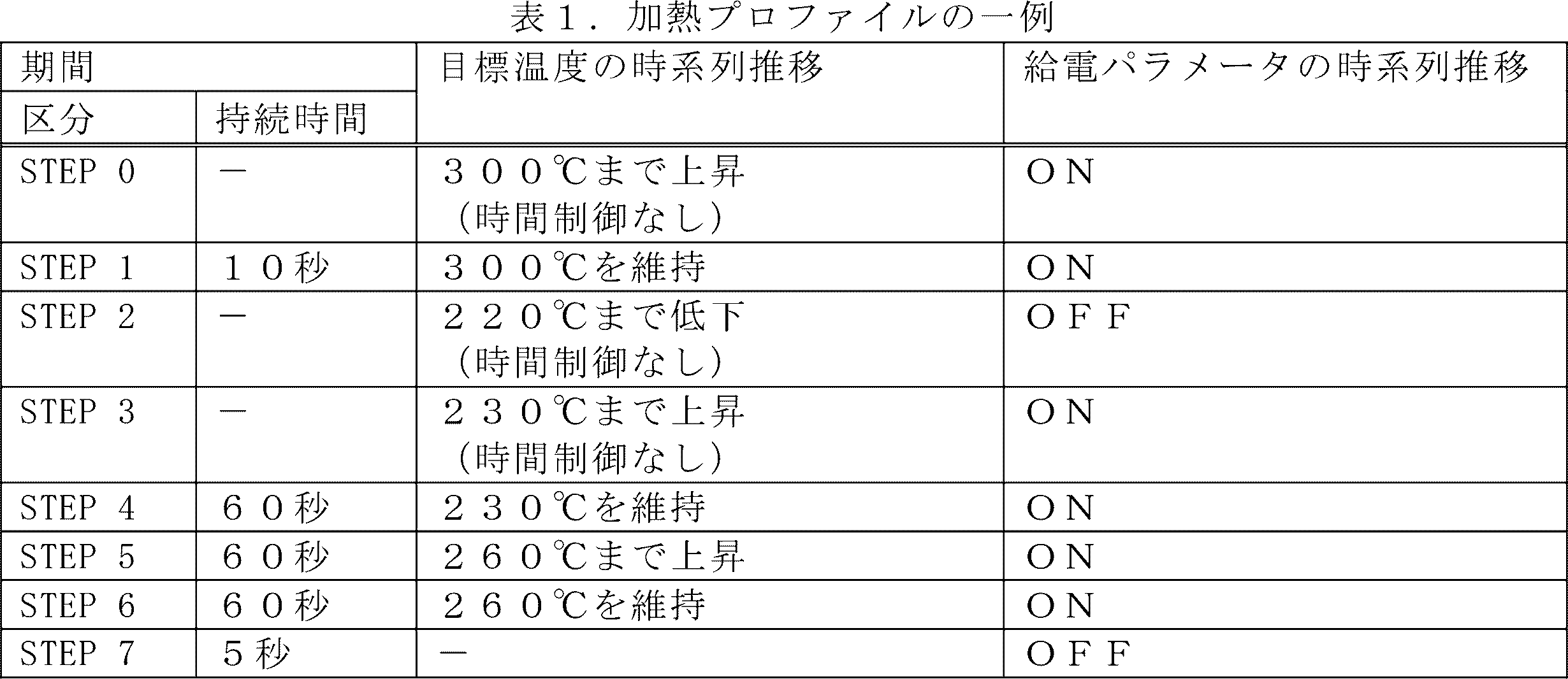
表1に示すように、加熱プロファイルは、複数の期間に区分され、各期間において目標温度の時系列推移、及び給電パラメータの時系列推移が規定されてよい。表1に示した例では、加熱プロファイルは、STEP0~STEP7の計8個の期間に区分されている。各STEPにおいて、目標温度の時系列推移、及び給電パラメータの時系列推移が規定される。加熱プロファイルに規定されたSTEPは、本実施形態における単位期間の一例である。
As shown in Table 1, the heating profile may be divided into a plurality of periods, and a time-series transition of the target temperature and a time-series transition of the power supply parameters may be defined in each period. In the example shown in Table 1, the heating profile is divided into a total of eight periods, STEP0 to STEP7. In each STEP, a time-series transition of the target temperature and a time-series transition of the power supply parameter are defined. STEP defined in the heating profile is an example of a unit period in this embodiment.
各STEPにおいて、時間制御が実施される場合がある。時間制御とは、所定の時間(即ち、各STEPに設定された持続時間)の経過をトリガとしてSTEPを終了する制御である。なお、時間制御が実施される場合、持続時間の終期に加熱部121の温度が目標温度に到達するよう、加熱部121の温度の変化速度が制御されてよい。他にも、時間制御が実施される場合、持続時間の途中で加熱部121の温度が目標温度に到達し、その後持続時間が経過するまで加熱部121の温度が目標温度を維持するよう、加熱部121の温度が制御されてよい。上記表1に示した例では、STEP1、及び4~7において時間制御が実施される。
Time control may be implemented in each STEP. Time control is control that terminates a STEP using the passage of a predetermined time (that is, the duration set for each STEP) as a trigger. Note that when time control is implemented, the rate of change in the temperature of the heating unit 121 may be controlled so that the temperature of the heating unit 121 reaches the target temperature at the end of the duration. In addition, when time control is implemented, heating is performed such that the temperature of the heating unit 121 reaches the target temperature in the middle of the duration time and then maintains the temperature of the heating unit 121 at the target temperature until the duration time elapses. The temperature of section 121 may be controlled. In the example shown in Table 1 above, time control is performed in STEP 1 and STEP 4 to 7.
各STEPにおいて、時間制御が実施されない場合がある。時間制御が実施されない場合、加熱部121の温度が所定の温度(即ち、各STEPに設定された目標温度)に到達したことをトリガとしてSTEPが終了する。そのため、時間制御が実施されないSTEPの持続時間は、温度変化速度に応じて拡縮する。上記表1に示した例では、STEP0、2及び3において時間制御が実施されない。
Time control may not be implemented in each STEP. If time control is not implemented, the STEP ends with the temperature of the heating section 121 reaching a predetermined temperature (that is, the target temperature set for each STEP) as a trigger. Therefore, the duration of STEP in which time control is not performed expands or contracts depending on the rate of temperature change. In the example shown in Table 1 above, time control is not performed in STEP 0, 2, and 3.
制御部116が表1に示した加熱プロファイルに従い温度制御を行った場合の、加熱部121の温度の推移について、図2を参照しながら説明する。図2は、表1に示した加熱プロファイルに基づき温度制御を行った場合の加熱部121の温度の推移の一例を示すグラフである。グラフ20の横軸は、時間(秒)である。グラフ20の縦軸は、加熱部121の温度である。線21は、加熱部121の温度の推移を示している。図2に示すように、加熱部121の温度は、加熱プロファイルにおいて規定された目標温度の推移と同様に推移している。以下、表1及び図2を参照しながら、加熱プロファイルの一例について説明する。
The transition of the temperature of the heating unit 121 when the control unit 116 performs temperature control according to the heating profile shown in Table 1 will be described with reference to FIG. 2. FIG. 2 is a graph showing an example of a change in temperature of the heating section 121 when temperature control is performed based on the heating profile shown in Table 1. The horizontal axis of the graph 20 is time (seconds). The vertical axis of the graph 20 is the temperature of the heating section 121. A line 21 indicates the change in temperature of the heating section 121. As shown in FIG. 2, the temperature of the heating section 121 changes in the same way as the target temperature defined in the heating profile. An example of a heating profile will be described below with reference to Table 1 and FIG. 2.
表1及び図2に示すように、STEP0において、加熱部121の温度は初期温度から300℃まで上昇する。初期温度とは、加熱開始時の加熱部121の温度である。STEP0においては、時間制御が実施されない。そのため、STEP0は、加熱部121の温度が300℃に到達したことをトリガとして、終了する。図2に示した例では、STEP0は、20秒で終了している。その後、STEP1において、加熱部121の温度は300℃に維持される。STEP1の終了をもって予備加熱期間が終了し、STEP2の開始と共にパフ可能期間が開始する。
As shown in Table 1 and FIG. 2, in STEP 0, the temperature of the heating section 121 rises from the initial temperature to 300°C. The initial temperature is the temperature of the heating section 121 at the start of heating. In STEP0, time control is not performed. Therefore, STEP0 ends when the temperature of the heating section 121 reaches 300° C. as a trigger. In the example shown in FIG. 2, STEP0 ends in 20 seconds. Thereafter, in STEP 1, the temperature of the heating section 121 is maintained at 300°C. The preheating period ends with the end of STEP 1, and the puffable period begins with the start of STEP 2.
ユーザにとっては、予備加熱時間が短い方が望ましい。ただし、スティック型基材150が十分に加熱されていない場合、スティック型基材150の内部に水分が蒸発しきれずに残ってしまう場合がある。その状態でユーザがパフを行うと、ユーザの口内に熱い水蒸気が送達されてしまうおそれがある。そのため、STEP0において加熱部121の温度を300℃に到達するまで急速に上昇させること、及びSTEP1の持続時間がある程度確保されることが望ましい。
For the user, a shorter preheating time is desirable. However, if the stick-type base material 150 is not heated sufficiently, the moisture may not completely evaporate and remain inside the stick-type base material 150. If the user puffs in this state, there is a risk that hot water vapor will be delivered into the user's mouth. Therefore, it is desirable that the temperature of the heating section 121 be rapidly raised to 300° C. in STEP 0, and that the duration of STEP 1 be secured to some extent.
表1及び図2に示すように、STEP2において、加熱部121の温度は220℃まで低下する。STEP2においては、時間制御が実施されない。そのため、STEP2は、加熱部121の温度が220℃に到達したことをトリガとして、終了する。図2に示した例では、STEP2は、10秒で終了している。STEP2においては、加熱部121への給電がOFFにされる。そのため、加熱部121の温度を最速で低下させることが可能となる。このように、加熱セッションの途中で加熱部121の温度を低下させることで、エアロゾル源の急速な消費を防止することができる。その結果、加熱セッションの途中でのエアロゾル源の枯渇を防止することが可能となる。
As shown in Table 1 and FIG. 2, in STEP 2, the temperature of the heating section 121 decreases to 220°C. In STEP2, time control is not performed. Therefore, STEP 2 is terminated when the temperature of the heating section 121 reaches 220° C. as a trigger. In the example shown in FIG. 2, STEP 2 ends in 10 seconds. In STEP2, the power supply to the heating section 121 is turned off. Therefore, it is possible to reduce the temperature of the heating section 121 at the fastest speed. In this way, by lowering the temperature of the heating section 121 in the middle of a heating session, rapid consumption of the aerosol source can be prevented. As a result, it is possible to prevent depletion of the aerosol source during the heating session.
表1及び図2に示すように、次に、STEP3において、加熱部121の温度は230℃まで上昇する。STEP3においては、時間制御が実施されない。そのため、STEP3は、加熱部121の温度が230℃に到達したことをトリガとして、終了する。図2に示した例では、STEP3は、5秒で終了している。このように、加熱部121の温度を低下させた後に再度上昇させる期間を設けることで、加熱部121の過度な降温を防止することが可能となる。
As shown in Table 1 and FIG. 2, next, in STEP 3, the temperature of the heating section 121 rises to 230°C. In STEP3, time control is not performed. Therefore, STEP 3 is terminated when the temperature of the heating section 121 reaches 230° C. as a trigger. In the example shown in FIG. 2, STEP3 ends in 5 seconds. In this way, by providing a period in which the temperature of the heating section 121 is lowered and then raised again, it is possible to prevent the temperature of the heating section 121 from excessively decreasing.
表1及び図2に示すように、次に、STEP4~STEP6にかけて、加熱部121の温度は260℃まで段階的に上昇する。このように、加熱部121の温度を緩やかに上昇させることで、エアロゾルの生成量を維持しつつ、加熱セッション全体における消費電力を抑制することが可能となる。
As shown in Table 1 and FIG. 2, next, from STEP 4 to STEP 6, the temperature of the heating section 121 increases stepwise to 260°C. In this way, by gradually increasing the temperature of the heating section 121, it is possible to maintain the amount of aerosol generated and to suppress power consumption during the entire heating session.
表1及び図2に示すように、STEP7において、加熱部121の温度は低下する。STEP7においては、加熱部121への給電がOFFにされる。STEP7では、持続時間が規定される一方で、目標温度は規定されない。そのため、STEP7は、持続時間終了をトリガとして終了する。STEP7においては、スティック型基材150の余熱により、十分な量のエアロゾルが生成され得る。そのため、本例では、STEP7の終了と共に、パフ可能期間、即ち加熱セッションが終了する。
As shown in Table 1 and FIG. 2, in STEP 7, the temperature of the heating section 121 decreases. In STEP7, the power supply to the heating section 121 is turned off. In STEP 7, while the duration is defined, the target temperature is not defined. Therefore, STEP7 ends using the end of the duration as a trigger. In STEP 7, a sufficient amount of aerosol can be generated by the residual heat of the stick-type base material 150. Therefore, in this example, the puffable period, that is, the heating session ends at the end of STEP7.
通知部113は、予備加熱が終了するタイミングを示す情報をユーザに通知してもよい。例えば、通知部113は、予備加熱が終了する前に予備加熱の終了を予告する情報を通知したり、予備加熱が終了したタイミングで予備加熱が終了したことを示す情報を通知したりする。ユーザへの通知は、例えば、LEDの点灯又は振動等により行われ得る。ユーザは、かかる通知を参考に、予備加熱の終了直後からパフを行うことが可能となる。
The notification unit 113 may notify the user of information indicating the timing at which preheating ends. For example, the notification unit 113 may notify information that foretells the end of preheating before the end of preheating, or may notify information indicating that preheating has ended at the timing when preheating has ended. The user may be notified by, for example, lighting an LED or vibrating. The user can refer to this notification and start puffing immediately after the end of preheating.
同様に、通知部113は、パフ可能期間が終了するタイミングを示す情報をユーザに通知してもよい。例えば、通知部113は、パフ可能期間が終了する前にパフ可能期間の終了を予告する情報を通知したり、パフ可能期間が終了したタイミングでパフ可能期間が終了したことを示す情報を通知したりする。ユーザへの通知は、例えば、LEDの点灯又は振動等により行われ得る。ユーザは、かかる通知を参考に、パフ可能期間が終了するまでパフを行うことが可能となる。
Similarly, the notification unit 113 may notify the user of information indicating the timing at which the puffable period ends. For example, the notification unit 113 may notify information foretelling the end of the puffable period before the puffable period ends, or notify information indicating that the puffable period has ended at the timing when the puffable period has ended. or The user may be notified by, for example, lighting an LED or vibrating. The user is able to puff until the puffing period ends with reference to this notification.
なお、上記説明した加熱プロファイルはあくまで一例であって、他の様々な例が考えられる。一例として、STEPの数、各STEPの持続時間、及び目標温度は、適宜変更されてよい。
Note that the heating profile described above is just an example, and various other examples are possible. As an example, the number of STEPs, the duration of each STEP, and the target temperature may be changed as appropriate.
<2.2.技術的課題>
上記表1及び図2に示した例において、加熱部121への給電が実施されるSTEPでは、制御部116は、ヒータ温度と目標温度とを照らし合わせて、加熱部121の動作を制御し得る。他方、STEP2のように、加熱部121への給電が実施されないSTEPでは、ヒータ温度の取得は困難である。そこで、制御部116は、サーミスタ温度と目標温度とを照らし合わせて、加熱部121の動作を制御し得る。 <2.2. Technical issues>
In the example shown in Table 1 and FIG. 2 above, in STEP where power is supplied to theheating unit 121, the control unit 116 can control the operation of the heating unit 121 by comparing the heater temperature with the target temperature. . On the other hand, in STEP 2, where power is not supplied to the heating unit 121, it is difficult to obtain the heater temperature. Therefore, the control unit 116 can control the operation of the heating unit 121 by comparing the thermistor temperature and the target temperature.
上記表1及び図2に示した例において、加熱部121への給電が実施されるSTEPでは、制御部116は、ヒータ温度と目標温度とを照らし合わせて、加熱部121の動作を制御し得る。他方、STEP2のように、加熱部121への給電が実施されないSTEPでは、ヒータ温度の取得は困難である。そこで、制御部116は、サーミスタ温度と目標温度とを照らし合わせて、加熱部121の動作を制御し得る。 <2.2. Technical issues>
In the example shown in Table 1 and FIG. 2 above, in STEP where power is supplied to the
ここで、サーミスタ117の電気抵抗値の測定精度が劣化する場合がある。原因の一例は、サーミスタ117の経年劣化である。その場合、STEP2のようにサーミスタ温度に基づいて加熱部121の動作を制御する期間において、加熱部121の動作を適切に制御することが困難になる。また、サーミスタ温度は、加熱部121の温度が過度に上昇する現象である熱暴走が発生した際に加熱部121による加熱を停止する等の保護機能のために使用され得る。サーミスタ117の電気抵抗値の測定精度が劣化した場合には、保護機能を適切に効かせることが困難になるおそれがある。このように、サーミスタ117の電気抵抗値の測定精度の劣化は、ユーザ体験の質の劣化を引き起こし得る。
Here, the measurement accuracy of the electrical resistance value of the thermistor 117 may deteriorate. One example of the cause is deterioration of the thermistor 117 over time. In that case, it becomes difficult to appropriately control the operation of the heating section 121 during a period in which the operation of the heating section 121 is controlled based on the thermistor temperature as in STEP2. Further, the thermistor temperature can be used for a protective function such as stopping heating by the heating unit 121 when thermal runaway, which is a phenomenon in which the temperature of the heating unit 121 rises excessively, occurs. If the measurement accuracy of the electrical resistance value of the thermistor 117 deteriorates, it may become difficult to properly apply the protection function. In this manner, deterioration in the measurement accuracy of the electrical resistance value of the thermistor 117 may cause deterioration in the quality of the user experience.
そこで、本実施形態では、サーミスタ117の電気抵抗値の測定精度の劣化に起因する、ユーザ体験の質の劣化を防止する仕組みを提供する。
Therefore, in this embodiment, a mechanism is provided to prevent the quality of the user experience from deteriorating due to the deterioration of the measurement accuracy of the electrical resistance value of the thermistor 117.
<2.3.加熱部121の動作制御>
(1)ヒータ温度とサーミスタ温度との差分に基づく制御
制御部116は、加熱部121の電気抵抗値とサーミスタ117の電気抵抗値とにより示されるヒータ温度とサーミスタ温度との差分に基づいて、加熱部121の動作を制御する。詳しくは、まず、制御部116は、加熱部121の電気抵抗値に基づいてヒータ温度を計算し、サーミスタ117の電気抵抗値に基づいてサーミスタ温度を計算する。次いで、制御部116は、ヒータ温度とサーミスタ温度との差分に基づいて、サーミスタ117の電気抵抗値の測定精度の劣化を判定する。そして、制御部116は、サーミスタ117の電気抵抗値の測定精度の劣化度合いに応じて、加熱部121の動作を制御する。かかる構成によれば、サーミスタ117の電気抵抗値の測定精度の劣化に起因するユーザ体験の質の劣化を、防止することが可能となる。 <2.3. Operation control ofheating section 121>
(1) Control based on the difference between heater temperature and thermistor temperature Thecontrol unit 116 performs heating based on the difference between the heater temperature and thermistor temperature indicated by the electrical resistance value of the heating section 121 and the electrical resistance value of the thermistor 117. The operation of the unit 121 is controlled. Specifically, first, the control unit 116 calculates the heater temperature based on the electrical resistance value of the heating unit 121 and calculates the thermistor temperature based on the electrical resistance value of the thermistor 117. Next, the control unit 116 determines deterioration in the measurement accuracy of the electrical resistance value of the thermistor 117 based on the difference between the heater temperature and the thermistor temperature. Then, the control unit 116 controls the operation of the heating unit 121 according to the degree of deterioration in the measurement accuracy of the electrical resistance value of the thermistor 117. According to this configuration, it is possible to prevent the quality of the user experience from deteriorating due to deterioration in the accuracy of measuring the electrical resistance value of the thermistor 117.
(1)ヒータ温度とサーミスタ温度との差分に基づく制御
制御部116は、加熱部121の電気抵抗値とサーミスタ117の電気抵抗値とにより示されるヒータ温度とサーミスタ温度との差分に基づいて、加熱部121の動作を制御する。詳しくは、まず、制御部116は、加熱部121の電気抵抗値に基づいてヒータ温度を計算し、サーミスタ117の電気抵抗値に基づいてサーミスタ温度を計算する。次いで、制御部116は、ヒータ温度とサーミスタ温度との差分に基づいて、サーミスタ117の電気抵抗値の測定精度の劣化を判定する。そして、制御部116は、サーミスタ117の電気抵抗値の測定精度の劣化度合いに応じて、加熱部121の動作を制御する。かかる構成によれば、サーミスタ117の電気抵抗値の測定精度の劣化に起因するユーザ体験の質の劣化を、防止することが可能となる。 <2.3. Operation control of
(1) Control based on the difference between heater temperature and thermistor temperature The
制御部116は、加熱部121への給電を制御するための根拠とするパラメータを、ヒータ温度とサーミスタ温度との差分に基づいて切り替えてもよい。かかる構成によれば、適切なパラメータを根拠にして、加熱部121の動作を制御することが可能となる。
The control unit 116 may switch the parameter used as the basis for controlling the power supply to the heating unit 121 based on the difference between the heater temperature and the thermistor temperature. According to this configuration, it is possible to control the operation of the heating section 121 based on appropriate parameters.
とりわけ、制御部116は、加熱部121への給電を一時的に停止した後に加熱部121への給電を再開するための根拠とするパラメータを、ヒータ温度とサーミスタ温度との差分に基づいて切り替えてもよい。表1及び図2を参照しながら上記説明したように、加熱セッションは、STEP2のように加熱部121の温度を一時的に低下させる期間を途中に含む。そして、制御部116は、加熱部121の温度を一時的に低下させる期間において、加熱部121への給電を停止する。その後、制御部116は、加熱部121への給電を再開する。とりわけ、制御部116は、ヒータ温度とサーミスタ温度との差分に基づいて選択したパラメータに基づくタイミングで、加熱部121への給電を再開する。かかる構成によれば、加熱部121の温度低下を、適切に制御することが可能となる。
In particular, the control unit 116 switches the parameter used as the basis for restarting the power supply to the heating unit 121 after temporarily stopping the power supply to the heating unit 121, based on the difference between the heater temperature and the thermistor temperature. Good too. As described above with reference to Table 1 and FIG. 2, the heating session includes a period during which the temperature of the heating unit 121 is temporarily lowered, as in STEP 2. Then, the control unit 116 stops power supply to the heating unit 121 during a period in which the temperature of the heating unit 121 is temporarily lowered. After that, the control unit 116 restarts power supply to the heating unit 121. In particular, the control unit 116 restarts power supply to the heating unit 121 at a timing based on a parameter selected based on the difference between the heater temperature and the thermistor temperature. According to this configuration, it becomes possible to appropriately control the temperature drop of the heating section 121.
以下、具体的な制御内容の一例を、図3を参照しながら説明する。図3は、本実施形態に係る加熱部121の動作の制御内容の一例を説明するための図である。図3では、ヒータ温度とサーミスタ温度との差分を縦軸とし、ヒータ温度とサーミスタ温度との差分に応じた制御内容が縦軸に沿って記載されている。
Hereinafter, an example of specific control contents will be explained with reference to FIG. 3. FIG. 3 is a diagram for explaining an example of the control content of the operation of the heating section 121 according to the present embodiment. In FIG. 3, the vertical axis represents the difference between the heater temperature and the thermistor temperature, and the control contents according to the difference between the heater temperature and the thermistor temperature are written along the vertical axis.
図3に示すように、制御部116は、ヒータ温度とサーミスタ温度との差分が第1の範囲に含まれる場合、サーミスタ温度に基づいて加熱部121への給電を再開してもよい。第1の範囲は、ヒータ温度とサーミスタ温度との差分が第1の範囲に含まれる場合に、ヒータ温度とサーミスタ温度とが同一であるとみなしてもよい範囲として設定される。一例として、第1の範囲は、±3℃の範囲である。例えば、制御部116は、ヒータ温度とサーミスタ温度との差分が第1の範囲に含まれる場合、加熱プロファイルに規定されたSTEP2の終期における目標温度までサーミスタ温度が低下したことをトリガとして、加熱部121への給電を再開する。かかる構成によれば、STEP2のようにヒータ温度を取得困難な期間においても、サーミスタ温度を代わりに参照することで、加熱プロファイルに規定された通りに加熱部121の温度を推移させることが可能となる。
As shown in FIG. 3, if the difference between the heater temperature and the thermistor temperature is within the first range, the control unit 116 may restart power supply to the heating unit 121 based on the thermistor temperature. The first range is set as a range in which the heater temperature and the thermistor temperature may be considered to be the same if the difference between the heater temperature and the thermistor temperature is included in the first range. As an example, the first range is a range of ±3°C. For example, when the difference between the heater temperature and the thermistor temperature is within the first range, the control unit 116 uses the thermistor temperature as a trigger to decrease to the target temperature at the end of STEP 2 specified in the heating profile, and controls the heating unit Restart power supply to 121. According to this configuration, even during a period where it is difficult to obtain the heater temperature as in STEP 2, by referring to the thermistor temperature instead, it is possible to make the temperature of the heating section 121 change as specified in the heating profile. Become.
図3に示すように、制御部116は、ヒータ温度とサーミスタ温度との差分が第1の範囲を超え、且つ第1の範囲よりも広い第2の範囲に含まれる場合、経過時間に基づいて加熱部121への給電を再開してもよい。第2の範囲は、ヒータ温度とサーミスタ温度との差分が第2の範囲に含まれる場合に、熱暴走等の不具合が発生し得ないと想定される範囲として設定される。一例として、第2の範囲は、±10℃の範囲である。例えば、制御部116は、ヒータ温度とサーミスタ温度との差分が第1の範囲を超え第2の範囲に含まれる場合、STEP2が開始されてから所定時間が経過したことをトリガとして、加熱部121への給電を再開する。当該所定時間は、加熱プロファイルに規定され得る。若しくは、当該所定時間は、STEP2における目標温度の低下幅に基づいて計算されてもよい。かかる構成によれば、ヒータ温度とサーミスタ温度とに誤差が生じており、サーミスタ温度に基づく制御が困難な場合であっても、加熱プロファイルに規定された目標温度から大幅に乖離しない範囲で加熱部121の温度を推移させることが可能となる。
As shown in FIG. 3, when the difference between the heater temperature and the thermistor temperature exceeds the first range and is included in a second range wider than the first range, the control unit 116 controls the difference based on the elapsed time. The power supply to the heating unit 121 may be restarted. The second range is set as a range in which it is assumed that problems such as thermal runaway will not occur if the difference between the heater temperature and the thermistor temperature is included in the second range. As an example, the second range is a range of ±10°C. For example, when the difference between the heater temperature and the thermistor temperature exceeds the first range and is included in the second range, the control unit 116 triggers the heating unit 121 when a predetermined time has elapsed since STEP 2 was started. Resume power supply to. The predetermined time can be defined in the heating profile. Alternatively, the predetermined time may be calculated based on the range of decrease in the target temperature in STEP2. According to this configuration, even if there is an error between the heater temperature and the thermistor temperature and it is difficult to control based on the thermistor temperature, the heating section can be adjusted within a range that does not significantly deviate from the target temperature specified in the heating profile. It becomes possible to change the temperature of 121.
図3に示すように、制御部116は、ヒータ温度とサーミスタ温度との差分が第2の範囲を超える場合、加熱部121への給電を禁止すること又は加熱部121への給電を停止することの少なくともいずれかひとつを実行してもよい。加熱部121への給電を停止することは、実行中の加熱部121への給電を停止することを指す概念である。加熱部121への給電を禁止することは、加熱部121への給電を停止することの他に、加熱部121への給電を実行しないことを含む概念である。かかる構成によれば、サーミスタ117の電気抵抗値の測定精度の劣化により保護機能がうまく効かない場合であっても、熱暴走等の不具合の発生を防止することが可能となる。
As shown in FIG. 3, when the difference between the heater temperature and the thermistor temperature exceeds the second range, the control unit 116 prohibits power supply to the heating unit 121 or stops power supply to the heating unit 121. You may perform at least one of the following. Stopping the power supply to the heating unit 121 is a concept that refers to stopping the power supply to the heating unit 121 during execution. Prohibiting power supply to heating unit 121 is a concept that includes not executing power supply to heating unit 121 in addition to stopping power supply to heating unit 121 . According to this configuration, even if the protection function does not work well due to deterioration in the measurement accuracy of the electrical resistance value of the thermistor 117, it is possible to prevent problems such as thermal runaway from occurring.
(2)ヒータ温度とサーミスタ温度との差分の取得タイミング
制御部116は、加熱セッションのうち一部の期間であるサンプリング期間においてヒータ温度とサーミスタ温度との差分を取得して記憶部114に記憶させてもよい。そして、制御部116は、記憶部114に記憶されたヒータ温度とサーミスタ温度との差分に基づいて、加熱部121の動作を制御してもよい。典型的には、制御部116は、ある加熱セッションにおいて取得したヒータ温度とサーミスタ温度との差分を、次回以降の加熱セッションにおける加熱部121の動作の制御に使用する。例えば、制御部116は、複数回の加熱セッションに1回の割合でサンプリング期間を設けてヒータ温度とサーミスタ温度との差分を取得し、取得したヒータ温度とサーミスタ温度との差分をその後の加熱セッションにおいて流用してもよい。かかる構成によれば、吸引装置100の処理負荷を軽減することが可能となる。もちろん、ある加熱セッションにおいて取得したヒータ温度とサーミスタ温度との差分が、同一の加熱セッションにおける加熱部121の動作の制御に使用されてもよい。 (2) Timing for acquiring the difference between the heater temperature and thermistor temperature Thecontrol unit 116 acquires the difference between the heater temperature and the thermistor temperature during a sampling period, which is a part of the heating session, and stores it in the storage unit 114. It's okay. Then, the control unit 116 may control the operation of the heating unit 121 based on the difference between the heater temperature and the thermistor temperature stored in the storage unit 114. Typically, the control unit 116 uses the difference between the heater temperature and thermistor temperature acquired in a certain heating session to control the operation of the heating unit 121 in the next heating session and thereafter. For example, the control unit 116 acquires the difference between the heater temperature and the thermistor temperature by setting a sampling period once in a plurality of heating sessions, and calculates the difference between the acquired heater temperature and thermistor temperature in subsequent heating sessions. It may also be used in According to this configuration, it is possible to reduce the processing load on the suction device 100. Of course, the difference between the heater temperature and thermistor temperature obtained in a certain heating session may be used to control the operation of the heating unit 121 in the same heating session.
制御部116は、加熱セッションのうち一部の期間であるサンプリング期間においてヒータ温度とサーミスタ温度との差分を取得して記憶部114に記憶させてもよい。そして、制御部116は、記憶部114に記憶されたヒータ温度とサーミスタ温度との差分に基づいて、加熱部121の動作を制御してもよい。典型的には、制御部116は、ある加熱セッションにおいて取得したヒータ温度とサーミスタ温度との差分を、次回以降の加熱セッションにおける加熱部121の動作の制御に使用する。例えば、制御部116は、複数回の加熱セッションに1回の割合でサンプリング期間を設けてヒータ温度とサーミスタ温度との差分を取得し、取得したヒータ温度とサーミスタ温度との差分をその後の加熱セッションにおいて流用してもよい。かかる構成によれば、吸引装置100の処理負荷を軽減することが可能となる。もちろん、ある加熱セッションにおいて取得したヒータ温度とサーミスタ温度との差分が、同一の加熱セッションにおける加熱部121の動作の制御に使用されてもよい。 (2) Timing for acquiring the difference between the heater temperature and thermistor temperature The
制御部116は、サンプリング期間においてヒータ温度とサーミスタ温度との差分を複数回取得し、複数のヒータ温度とサーミスタ温度との差分の統計値を記憶部114に記憶させてもよい。そして、制御部116は、記憶部114に記憶されたヒータ温度とサーミスタ温度との差分の統計値に基づいて、加熱部121の動作を制御してもよい。統計値は、平均値、重み付き平均値、又は中央値等、多様な統計手法により計算され得る。かかる構成によれば、サーミスタ117の電気抵抗値の測定精度の劣化をより精度よく判定することが可能となる。
The control unit 116 may obtain the difference between the heater temperature and the thermistor temperature multiple times during the sampling period, and store the statistical values of the differences between the multiple heater temperatures and the thermistor temperature in the storage unit 114. The control unit 116 may control the operation of the heating unit 121 based on the statistical value of the difference between the heater temperature and the thermistor temperature stored in the storage unit 114. Statistics can be calculated by various statistical techniques, such as an average, a weighted average, or a median. According to this configuration, it becomes possible to more accurately determine the deterioration in the measurement accuracy of the electrical resistance value of the thermistor 117.
サンプリング期間は、加熱部121の温度を一時的に低下させる期間よりも後の期間であることが望ましい。表1及び図2を参照しながら説明した例では、サンプリング期間は、STEP3以降の期間であることが望ましい。STEP0及びSTEP1においては、ヒータ温度が急激に上昇している、又は急激に上昇した直後であるから、ヒータ温度とサーミスタ温度との間に大きな差分が自然に発生する。サーミスタ温度は、ヒータ温度に追随しつつも遅れて上昇するためである。即ち、STEP0及びSTEP1におけるヒータ温度とサーミスタ温度との差分は、サーミスタ117の電気抵抗値の測定精度の劣化に起因する値と、サーミスタ温度の昇温の遅れに起因する値と、の和となる。他方、STEP3以降では、サーミスタ温度はヒータ温度に漸近するまで十分に上昇していると考えられる。即ち、STEP3以降におけるヒータ温度とサーミスタ温度との差分は、サーミスタ温度の昇温の遅れに起因する値を含まず、サーミスタ117の電気抵抗値の測定精度の劣化に起因する値のみを含むものに収束していると考えらえる。従って、かかる構成によれば、サーミスタ117の電気抵抗値の測定精度の劣化をより精度よく判定することが可能となる。
It is desirable that the sampling period be a period after the period in which the temperature of the heating section 121 is temporarily lowered. In the example described with reference to Table 1 and FIG. 2, the sampling period is preferably the period after STEP 3. In STEP 0 and STEP 1, the heater temperature is rapidly increasing or has just risen rapidly, so a large difference naturally occurs between the heater temperature and the thermistor temperature. This is because the thermistor temperature follows the heater temperature but increases with a delay. That is, the difference between the heater temperature and the thermistor temperature in STEP 0 and STEP 1 is the sum of the value caused by the deterioration in measurement accuracy of the electrical resistance value of the thermistor 117 and the value caused by the delay in the temperature rise of the thermistor temperature. . On the other hand, after STEP 3, the thermistor temperature is considered to have risen sufficiently until it asymptotically approaches the heater temperature. That is, the difference between the heater temperature and the thermistor temperature after STEP 3 does not include the value caused by the delay in the temperature rise of the thermistor temperature, but only includes the value caused by the deterioration in the measurement accuracy of the electrical resistance value of the thermistor 117. It seems to be converging. Therefore, with this configuration, it is possible to more accurately determine the deterioration in the measurement accuracy of the electrical resistance value of the thermistor 117.
ここで、短い間隔でスティック型基材150を差し替えながら複数回加熱する、いわゆるチェーンスモークが行われる場合がある。チェーンスモークが行われる場合、2回目以降の加熱時の加熱部121の初期温度は、1回目の加熱時の加熱部121の初期温度と比較して高くなる。そして、初期温度が高いほど、ヒータ温度とサーミスタ温度との差分が収束するタイミングは早まる。
Here, so-called chain smoking may be performed, in which the stick-shaped base material 150 is heated multiple times while being replaced at short intervals. When chain smoking is performed, the initial temperature of the heating unit 121 during the second and subsequent heating is higher than the initial temperature of the heating unit 121 during the first heating. The higher the initial temperature, the earlier the timing at which the difference between the heater temperature and thermistor temperature converges.
そこで、制御部116は、加熱部121の初期温度に基づいて、サンプリング期間を設定してもよい。とりわけ、制御部116は、加熱部121の初期温度が高いほど、サンプリング期間を開始するタイミングを早くに設定してもよい。加熱部121の初期温度としては、加熱開始時、即ち加熱プロファイルに基づく加熱部121による加熱を開始する際の、ヒータ温度が使用されてよい。例えば、制御部116は、加熱開始時のヒータ温度が所定の閾値未満である場合、STEP5及びSTEP6を、サンプリング期間として設定してもよい。他方、制御部116は、加熱開始時のヒータ温度が所定の閾値以上である場合、STEP3~STEP6を、サンプリング期間として設定してもよい。かかる構成によれば、チェーンスモークが行われヒータ温度とサーミスタ温度との差分が早くに収束する場合に長いサンプリング期間を確保して、サーミスタ117の電気抵抗値の測定精度の劣化を精度よく判定することが可能となる。
Therefore, the control unit 116 may set the sampling period based on the initial temperature of the heating unit 121. In particular, the control unit 116 may set the timing to start the sampling period earlier as the initial temperature of the heating unit 121 is higher. As the initial temperature of the heating section 121, the heater temperature at the time of starting heating, that is, when the heating section 121 starts heating based on the heating profile may be used. For example, if the heater temperature at the start of heating is less than a predetermined threshold, the control unit 116 may set STEP 5 and STEP 6 as the sampling period. On the other hand, if the heater temperature at the start of heating is equal to or higher than a predetermined threshold, the control unit 116 may set STEP 3 to STEP 6 as the sampling period. According to this configuration, when chain smoking is performed and the difference between the heater temperature and the thermistor temperature converges quickly, a long sampling period is ensured to accurately determine the deterioration in the measurement accuracy of the electrical resistance value of the thermistor 117. becomes possible.
制御部116は、加熱開始時のヒータ温度と共に、又は代えて、チェーンスモークの有無に影響を受ける他の情報に基づいて、サンプリング期間を設定してもよい。一例として、制御部116は、加熱開始時のサーミスタ温度に基づいて、サンプリング期間を設定してもよい。その場合、制御部116は、加熱開始時のサーミスタ温度が高いほど、サンプリング期間が開始するタイミングを早くに設定してもよい。他の一例として、制御部116は、加熱プロファイルに基づく加熱を前回実行してから今回実行するまでの経過時間に基づいて、サンプリング期間を設定してもよい。その場合、制御部116は、加熱プロファイルに基づく加熱を前回実行してから今回実行するまでの経過時間が短いほど、サンプリング期間が開始するタイミングを早くに設定してもよい。いずれの構成も、チェーンスモークが行われヒータ温度とサーミスタ温度との差分が早くに収束する場合に長いサンプリング期間を確保して、サーミスタ117の劣化を精度よく判定することが可能となる。
The control unit 116 may set the sampling period based on the heater temperature at the start of heating, or instead, based on other information affected by the presence or absence of chain smoke. As an example, the control unit 116 may set the sampling period based on the thermistor temperature at the start of heating. In that case, the control unit 116 may set the timing at which the sampling period starts earlier as the thermistor temperature at the start of heating is higher. As another example, the control unit 116 may set the sampling period based on the elapsed time from the previous execution of heating based on the heating profile until the current execution. In that case, the control unit 116 may set the timing at which the sampling period starts earlier as the elapsed time from the previous execution of heating based on the heating profile to the current execution is shorter. In either configuration, when chain smoke is performed and the difference between the heater temperature and the thermistor temperature converges quickly, a long sampling period can be ensured, making it possible to accurately determine the deterioration of the thermistor 117.
(3)個体差の吸収
制御部116は、加熱部121による加熱が初めて実行された際に取得されたヒータ温度とサーミスタ温度との差分に基づいて、第1の範囲及び第2の範囲を設定してもよい。
例えば、制御部116は、加熱部121による加熱が初めて実行された際に取得されたヒータ温度とサーミスタ温度との差分の基準とする、±3℃の範囲を第1の範囲として設定し、±10℃の範囲を第2の範囲として設定する。加熱部121による加熱が初めて実行された際とは、例えば、吸引装置100が出荷され購入された後に初めて加熱が実行されたタイミングを指す。加熱部121による加熱が初めて実行された際に取得されたヒータ温度とサーミスタ温度との差分は、加熱部121又はサーミスタ117の個体差に対応する。かかる構成によれば、加熱部121又はサーミスタ117の個体差を吸収して、加熱部121の動作を適切に制御することが可能となる。 (3) Absorption of individual differences Thecontrol unit 116 sets the first range and the second range based on the difference between the heater temperature and thermistor temperature obtained when heating by the heating unit 121 is performed for the first time. You may.
For example, thecontrol unit 116 sets a range of ±3° C. as a first range, which is the reference for the difference between the heater temperature and thermistor temperature obtained when heating by the heating unit 121 is performed for the first time, and A range of 10°C is set as the second range. The first time heating by the heating unit 121 is performed refers to, for example, the timing when heating is performed for the first time after the suction device 100 is shipped and purchased. The difference between the heater temperature and the thermistor temperature obtained when heating by the heating section 121 is performed for the first time corresponds to the individual difference between the heating section 121 or the thermistor 117. According to this configuration, it is possible to absorb individual differences between the heating section 121 or the thermistor 117 and appropriately control the operation of the heating section 121.
制御部116は、加熱部121による加熱が初めて実行された際に取得されたヒータ温度とサーミスタ温度との差分に基づいて、第1の範囲及び第2の範囲を設定してもよい。
例えば、制御部116は、加熱部121による加熱が初めて実行された際に取得されたヒータ温度とサーミスタ温度との差分の基準とする、±3℃の範囲を第1の範囲として設定し、±10℃の範囲を第2の範囲として設定する。加熱部121による加熱が初めて実行された際とは、例えば、吸引装置100が出荷され購入された後に初めて加熱が実行されたタイミングを指す。加熱部121による加熱が初めて実行された際に取得されたヒータ温度とサーミスタ温度との差分は、加熱部121又はサーミスタ117の個体差に対応する。かかる構成によれば、加熱部121又はサーミスタ117の個体差を吸収して、加熱部121の動作を適切に制御することが可能となる。 (3) Absorption of individual differences The
For example, the
なお、加熱部121又はサーミスタ117の個体差を吸収するための他の一案として、工場出荷前に、ヒータ温度とサーミスタ温度とが一致する又はヒータ温度とサーミスタ温度との差分が所定の範囲に含まれるよう、ヒータ温度又はサーミスタ温度の算出方法がキャリブレーションされてもよい。ヒータ温度の算出方法をキャリブレーションすることは、加熱部121の電気抵抗値と当該電気抵抗値から計算されるヒータ温度との対応関係を設定することを指す。サーミスタ温度の算出方法をキャリブレーションすることは、サーミスタ117の電気抵抗値と当該電気抵抗値から計算されるサーミスタ温度との対応関係を設定することを指す。一例として、加熱プロファイルに規定された任意の目標温度にヒータ温度が達したタイミングにおいて、ヒータ温度とサーミスタ温度とが一致する又はヒータ温度とサーミスタ温度との差分が所定の範囲に含まれるよう、ヒータ温度又はサーミスタ温度の算出方法がキャリブレーションされる。キャリブレーションは、加熱プロファイルに規定された複数の目標温度に関し行われてもよい。
Another option for absorbing individual differences in the heating section 121 or thermistor 117 is to make sure that the heater temperature and thermistor temperature match or that the difference between the heater temperature and thermistor temperature falls within a predetermined range before shipment from the factory. The method for calculating the heater temperature or thermistor temperature may be calibrated to include the above. Calibrating the heater temperature calculation method refers to setting a correspondence between the electrical resistance value of the heating section 121 and the heater temperature calculated from the electrical resistance value. Calibrating the thermistor temperature calculation method refers to setting a correspondence between the electrical resistance value of the thermistor 117 and the thermistor temperature calculated from the electrical resistance value. As an example, at the timing when the heater temperature reaches an arbitrary target temperature specified in the heating profile, the heater temperature is adjusted so that the heater temperature and the thermistor temperature match or the difference between the heater temperature and the thermistor temperature is within a predetermined range. The temperature or thermistor temperature calculation method is calibrated. Calibration may be performed for multiple target temperatures defined in the heating profile.
(4)処理の流れ
以下では、図4を参照しながら、本実施形態に係る吸引装置100により実行される処理の流れを説明する。図4は、本実施形態に係る吸引装置100により実行される処理の流れの一例を示すフローチャートである。 (4) Process Flow Below, the process flow executed by thesuction device 100 according to the present embodiment will be described with reference to FIG. FIG. 4 is a flowchart illustrating an example of the flow of processing executed by the suction device 100 according to the present embodiment.
以下では、図4を参照しながら、本実施形態に係る吸引装置100により実行される処理の流れを説明する。図4は、本実施形態に係る吸引装置100により実行される処理の流れの一例を示すフローチャートである。 (4) Process Flow Below, the process flow executed by the
図4に示すように、まず、制御部116は、加熱開始を指示するユーザ操作を取得する(ステップS102)。加熱開始を指示するユーザ操作の一例は、吸引装置100に設けられたスイッチ等を操作すること等の、吸引装置100に対する操作である。加熱開始を指示するユーザ操作の他の一例は、吸引装置100にスティック型基材150を挿入することである。
As shown in FIG. 4, first, the control unit 116 obtains a user operation instructing to start heating (step S102). An example of a user operation to instruct the start of heating is an operation on the suction device 100, such as operating a switch provided on the suction device 100. Another example of a user operation to instruct the start of heating is to insert the stick-shaped base material 150 into the suction device 100.
次いで、制御部116は、前回の加熱セッションにおいて取得されたヒータ温度とサーミスタ温度との差分が第2の範囲に含まれるか否かを判定する(ステップS104)。例えば、制御部116は、記憶部114に記憶された、前回の加熱セッションにおいて取得されたヒータ温度とサーミスタ温度との差分を参照して、かかる判定を行う。
Next, the control unit 116 determines whether the difference between the heater temperature and thermistor temperature acquired in the previous heating session is included in the second range (step S104). For example, the control unit 116 makes this determination by referring to the difference between the heater temperature and the thermistor temperature acquired in the previous heating session, which is stored in the storage unit 114.
前回の加熱セッションにおいて取得されたヒータ温度とサーミスタ温度との差分が第2の範囲に含まれないと判定された場合(ステップS104:NO)、制御部116は、加熱を禁止する(ステップS108)。即ち、制御部116は、加熱部121への給電を実行せずに処理を終了する。
If it is determined that the difference between the heater temperature and thermistor temperature acquired in the previous heating session is not included in the second range (step S104: NO), the control unit 116 prohibits heating (step S108). . That is, the control unit 116 ends the process without supplying power to the heating unit 121.
他方、前回の加熱セッションにおいて取得されたヒータ温度とサーミスタ温度との差分が第2の範囲に含まれると判定された場合(ステップS104:YES)、制御部116は、加熱を開始する。即ち、制御部116は、加熱部121への給電を開始する。
On the other hand, if it is determined that the difference between the heater temperature and thermistor temperature acquired in the previous heating session is within the second range (step S104: YES), the control unit 116 starts heating. That is, the control unit 116 starts supplying power to the heating unit 121.
次いで、制御部116は、加熱部121の初期温度を取得する(ステップS110)。例えば、制御部116は、加熱部121への給電開始時のヒータ温度を取得する。
Next, the control unit 116 obtains the initial temperature of the heating unit 121 (step S110). For example, the control unit 116 acquires the heater temperature at the time when power supply to the heating unit 121 is started.
次に、制御部116は、加熱部121の初期温度に基づいて、サンプリング期間を設定する(ステップS112)。
Next, the control unit 116 sets a sampling period based on the initial temperature of the heating unit 121 (step S112).
次いで、制御部116は、加熱を一時的にOFFにするか否かを判定する(ステップS114)。例えば、制御部116は、表1に示した加熱プロファイルにおけるSTEP2が開始した場合に、加熱部121への給電を一時的停止し、加熱を一時的にOFFにすると判定する。
Next, the control unit 116 determines whether to temporarily turn off the heating (step S114). For example, when STEP 2 in the heating profile shown in Table 1 starts, the control unit 116 determines to temporarily stop the power supply to the heating unit 121 and temporarily turn off the heating.
加熱を一時的にOFFにしないと判定された場合(ステップS114:NO)、処理はステップS126に進む。
If it is determined that the heating is not to be temporarily turned off (step S114: NO), the process proceeds to step S126.
加熱を一時的にOFFにすると判定された場合(ステップS114:YES)、制御部116は、加熱部121への給電を停止し、加熱をOFFにする(ステップS116)。
If it is determined that the heating should be temporarily turned off (step S114: YES), the control unit 116 stops power supply to the heating unit 121 and turns off the heating (step S116).
次いで、制御部116は、前回の加熱セッションにおいて取得されたヒータ温度とサーミスタ温度との差分が第1の範囲に含まれるか否かを判定する(ステップS118)。例えば、制御部116は、記憶部114に記憶された、前回の加熱セッションにおいて取得されたヒータ温度とサーミスタ温度との差分を参照して、かかる判定を行う。
Next, the control unit 116 determines whether the difference between the heater temperature and the thermistor temperature acquired in the previous heating session is included in the first range (step S118). For example, the control unit 116 makes this determination by referring to the difference between the heater temperature and the thermistor temperature acquired in the previous heating session, which is stored in the storage unit 114.
前回の加熱セッションにおいて取得されたヒータ温度とサーミスタ温度との差分が第1の範囲に含まれると判定された場合(ステップS118:YES)、制御部116は、サーミスタ温度に基づいて加熱を再開する(ステップS120)。例えば、STEP2において加熱を一時的にOFFにした場合、STEP2の終期に設定された目標温度までサーミスタ温度が低下したことをトリガとして、STEP2を終了し、加熱部121への給電を再開する。その後、処理はステップS124に進む。
If it is determined that the difference between the heater temperature and thermistor temperature acquired in the previous heating session is within the first range (step S118: YES), the control unit 116 restarts heating based on the thermistor temperature. (Step S120). For example, when heating is temporarily turned off in STEP 2, STEP 2 is terminated and power supply to the heating unit 121 is restarted using the thermistor temperature falling to the target temperature set at the end of STEP 2 as a trigger. After that, the process proceeds to step S124.
前回の加熱セッションにおいて取得されたヒータ温度とサーミスタ温度との差分が第1の範囲に含まれないと判定された場合(ステップS118:NO)、制御部116は、時間経過に基づいて加熱を再開する(ステップS122)。例えば、STEP2において加熱を一時的にOFFにしてからの経過時間が所定時間に達したことをトリガとして、STEP2を終了し、加熱部121への給電を再開する。その後、処理はステップS124に進む。
If it is determined that the difference between the heater temperature and thermistor temperature acquired in the previous heating session is not included in the first range (step S118: NO), the control unit 116 restarts heating based on the passage of time. (Step S122). For example, when the elapsed time after heating is temporarily turned off in STEP 2 reaches a predetermined time, as a trigger, STEP 2 is ended and power supply to the heating unit 121 is restarted. After that, the process proceeds to step S124.
ステップS124において、制御部116は、サンプリング期間においてヒータ温度とサーミスタ温度との差分を取得して、記憶部114に記憶させる(ステップS124)。
In step S124, the control unit 116 acquires the difference between the heater temperature and the thermistor temperature during the sampling period, and stores it in the storage unit 114 (step S124).
次いで、制御部116は、終了条件が満たされたか否かを判定する(ステップS126)。終了条件の一例は、STEP7の持続時間が経過したことである。終了条件の他の一例は、加熱開始からのパフ回数が所定回数に達したことである。
Next, the control unit 116 determines whether the termination condition is satisfied (step S126). An example of the termination condition is that the duration of STEP 7 has elapsed. Another example of the termination condition is that the number of puffs since the start of heating has reached a predetermined number.
終了条件が満たされていないと判定された場合(ステップS126:NO)、処理はステップS114に戻る。
If it is determined that the termination condition is not satisfied (step S126: NO), the process returns to step S114.
他方、終了条件が満たされたと判定された場合(ステップS126:YES)、制御部116は、加熱プロファイルに基づく加熱を終了する(ステップS128)。その後、処理は終了する。
On the other hand, if it is determined that the termination condition is satisfied (step S126: YES), the control unit 116 terminates the heating based on the heating profile (step S128). The process then ends.
<3.補足>
以上、添付図面を参照しながら本開示の好適な実施形態について詳細に説明したが、本開示はかかる例に限定されない。本開示の属する技術の分野における通常の知識を有する者であれば、請求の範囲に記載された技術的思想の範疇内において、各種の変更例または修正例に想到し得ることは明らかであり、これらについても、当然に本開示の技術的範囲に属するものと了解される。 <3. Supplement>
Although preferred embodiments of the present disclosure have been described above in detail with reference to the accompanying drawings, the present disclosure is not limited to such examples. It is clear that a person with ordinary knowledge in the technical field to which this disclosure pertains can come up with various changes or modifications within the scope of the technical idea described in the claims. It is understood that these also naturally fall within the technical scope of the present disclosure.
上記実施形態では、加熱プロファイルが、加熱部121の温度の目標値を含む例を説明したが、本開示はかかる例に限定されない。加熱プロファイルは、加熱部121の温度に対応するパラメータの目標値を含んでいればよい。加熱部121の温度に対応するパラメータとしては、加熱部121の電気抵抗値又はサーミスタ117の電気抵抗値が挙げられる。
In the above embodiment, an example has been described in which the heating profile includes the target value of the temperature of the heating section 121, but the present disclosure is not limited to such an example. The heating profile only needs to include target values of parameters corresponding to the temperature of the heating section 121. Parameters corresponding to the temperature of the heating section 121 include the electrical resistance value of the heating section 121 or the electrical resistance value of the thermistor 117.
上記実施形態では、加熱部121が抵抗発熱体として構成され、電気抵抗により発熱する例を説明したが、本開示はかかる例に限定されない。例えば、加熱部121は、磁場を発生させるコイル等の電磁誘導源と、誘導加熱により発熱するサセプタと、を含んでいてもよく、サセプタによりスティック型基材150が加熱されてもよい。この場合、制御部116は、電磁誘導源に交流電流を印可して交番磁場を発生させ、サセプタに交番磁場を侵入させることで、サセプタを発熱させる。誘導加熱により発熱するサセプタは、吸引装置100に設けられ得る。この場合、加熱プロファイルに基づいて制御されるエアロゾル源を加熱する温度は、サセプタの温度となる。サセプタの温度は、電磁誘導源の電気抵抗値に基づいて推定可能である。
In the above embodiment, an example has been described in which the heating section 121 is configured as a resistance heating element and generates heat by electric resistance, but the present disclosure is not limited to such an example. For example, the heating unit 121 may include an electromagnetic induction source such as a coil that generates a magnetic field, and a susceptor that generates heat by induction heating, and the stick-shaped base material 150 may be heated by the susceptor. In this case, the control unit 116 applies an alternating current to the electromagnetic induction source to generate an alternating magnetic field, and causes the alternating magnetic field to enter the susceptor, thereby causing the susceptor to generate heat. A susceptor that generates heat by induction heating may be provided in the suction device 100. In this case, the temperature at which the aerosol source is heated, which is controlled based on the heating profile, will be the temperature of the susceptor. The temperature of the susceptor can be estimated based on the electrical resistance value of the electromagnetic induction source.
なお、本明細書において説明した各装置による一連の処理は、ソフトウェア、ハードウェア、及びソフトウェアとハードウェアとの組合せのいずれを用いて実現されてもよい。ソフトウェアを構成するプログラムは、例えば、各装置の内部又は外部に設けられる記録媒体(詳しくは、コンピュータにより読み取り可能な非一時的な記憶媒体)に予め格納される。そして、各プログラムは、例えば、本明細書において説明した各装置を制御するコンピュータによる実行時にRAMに読み込まれ、CPUなどの処理回路により実行される。上記記録媒体は、例えば、磁気ディスク、光ディスク、光磁気ディスク、フラッシュメモリ等である。また、上記のコンピュータプログラムは、記録媒体を用いずに、例えばネットワークを介して配信されてもよい。また、上記のコンピュータは、ASICのような特定用途向け集積回路、ソフトウエアプログラムを読み込むことで機能を実行する汎用プロセッサ、又はクラウドコンピューティングに使用されるサーバ上のコンピュータ等であってよい。また、本明細書において説明した各装置による一連の処理は、複数のコンピュータにより分散して処理されてもよい。
Note that the series of processes performed by each device described in this specification may be realized using software, hardware, or a combination of software and hardware. A program constituting the software is stored in advance, for example, in a recording medium (specifically, a computer-readable non-temporary storage medium) provided inside or outside each device. For example, each program is read into the RAM when executed by a computer that controls each device described in this specification, and is executed by a processing circuit such as a CPU. The recording medium is, for example, a magnetic disk, an optical disk, a magneto-optical disk, a flash memory, or the like. Furthermore, the above computer program may be distributed, for example, via a network, without using a recording medium. Further, the above-mentioned computer may be an application-specific integrated circuit such as an ASIC, a general-purpose processor that executes functions by loading a software program, or a computer on a server used for cloud computing. Furthermore, a series of processes performed by each device described in this specification may be distributed and processed by multiple computers.
また、本明細書においてフローチャート及びシーケンス図を用いて説明した処理は、必ずしも図示された順序で実行されなくてもよい。いくつかの処理ステップは、並列的に実行されてもよい。また、追加的な処理ステップが採用されてもよく、一部の処理ステップが省略されてもよい。
Furthermore, the processes described using flowcharts and sequence diagrams in this specification do not necessarily have to be executed in the order shown. Some processing steps may be performed in parallel. Also, additional processing steps may be employed or some processing steps may be omitted.
なお、以下のような構成も本開示の技術的範囲に属する。
(1)
電源部と、
前記電源部から供給された電力を使用してエアロゾル源を加熱する加熱部と、
前記加熱部の温度変化に追随して温度変化する温度変化部と、
前記加熱部の温度に対応するパラメータとして測定された第1の測定値と前記温度変化部の温度に対応するパラメータとして測定された第2の測定値とにより示される、前記加熱部の温度と前記温度変化部の温度との差分に基づいて、前記加熱部の動作を制御する制御部と、
を備えるエアロゾル生成システム。
(2)
前記制御部は、前記加熱部への給電を制御するための根拠とするパラメータを、前記加熱部の温度と前記温度変化部の温度との差分に基づいて切り替える、
前記(1)に記載のエアロゾル生成システム。
(3)
前記制御部は、前記加熱部への給電を一時的に停止した後に前記加熱部への給電を再開する根拠とするパラメータを、前記加熱部の温度と前記温度変化部の温度との差分に基づいて切り替える、
前記(2)に記載のエアロゾル生成システム。
(4)
前記制御部は、前記加熱部の温度と前記温度変化部の温度との差分が第1の範囲に含まれる場合、前記第2の測定値に基づいて前記加熱部への給電を再開する、
前記(3)に記載のエアロゾル生成システム。
(5)
前記制御部は、前記加熱部の温度と前記温度変化部の温度との差分が前記第1の範囲を超え、且つ前記第1の範囲よりも広い第2の範囲に含まれる場合、経過時間に基づいて前記加熱部への給電を再開する、
前記(4)に記載のエアロゾル生成システム。
(6)
前記制御部は、前記加熱部の温度と前記温度変化部の温度との差分が前記第2の範囲を超える場合、前記加熱部への給電を停止すること又は前記加熱部への給電を禁止することの少なくともいずれかひとつを実行する、
前記(5)に記載のエアロゾル生成システム。
(7)
前記制御部は、前記加熱部による加熱が初めて実行された際に取得された前記加熱部の温度と前記温度変化部の温度との差分に基づいて、前記第1の範囲及び前記第2の範囲を設定する、
前記(5)又は(6)に記載のエアロゾル生成システム。
(8)
前記エアロゾル生成システムは、情報を記憶する記憶部を備え、
前記制御部は、
前記エアロゾル源を加熱する温度の目標値の時系列推移を規定した制御情報に基づいて前記加熱部の動作を制御し、
前記制御情報により前記目標値の時系列推移が規定される期間の一部であるサンプリング期間において前記加熱部の温度と前記温度変化部の温度との差分を取得して前記記憶部に記憶させ、
前記記憶部に記憶された前記加熱部の温度と前記温度変化部の温度との差分に基づいて、前記加熱部の動作を制御する、
前記(1)~(7)のいずれか一項に記載のエアロゾル生成システム。
(9)
前記制御部は、前記サンプリング期間において前記加熱部の温度と前記温度変化部の温度との差分を複数回取得し、複数の前記加熱部の温度と前記温度変化部の温度との差分の統計値を前記記憶部に記憶させ、
前記記憶部に記憶された前記加熱部の温度と前記温度変化部の温度との差分の前記統計値に基づいて、前記加熱部の動作を制御する、
前記(8)に記載のエアロゾル生成システム。
(10)
前記制御情報により前記目標値の時系列推移が規定される期間は、前記加熱部の温度を一時的に低下させる期間を途中に含み、
前記制御部は、前記加熱部の温度を低下させる期間において前記加熱部への給電を停止し、
前記サンプリング期間は、前記加熱部の温度を低下させる期間よりも後の期間である、
前記(8)又は(9)に記載のエアロゾル生成システム。
(11)
前記制御部は、前記制御情報に基づく前記加熱部による加熱を開始する際の前記第1の測定値に基づいて、前記サンプリング期間を設定する、
前記(10)に記載のエアロゾル生成システム。
(12)
前記制御部は、前記制御情報に基づく前記加熱部による加熱を開始する際の前記第1の測定値により示される前記加熱部の温度が高いほど、前記サンプリング期間を開始するタイミングを早くに設定する、
前記(11)に記載のエアロゾル生成システム。
(13)
前記加熱部は、電流が印可された場合に発熱する抵抗発熱体であり、
第1の測定値は、前記抵抗発熱体の電気抵抗値であり、
前記温度変化部は、温度変化に応じて電気抵抗値が変化する抵抗体であり、
第2の測定値は、前記抵抗体の電気抵抗値である、
前記(1)~(12)のいずれか一項に記載のエアロゾル生成システム。
(14)
前記エアロゾル生成システムは、前記エアロゾル源を含有した基材をさらに備える、
前記(1)~(13)のいずれか一項に記載のエアロゾル生成システム。
(15)
エアロゾル生成システムを制御するための制御方法であって、
前記エアロゾル生成システムは、
電源部と、
前記電源部から供給された電力を使用してエアロゾル源を加熱する加熱部と、
前記加熱部の温度変化に追随して温度変化する温度変化部と、
を備え、
前記制御方法は、
前記加熱部の温度に対応する値として測定された第1の測定値と前記温度変化部の温度に対応する値として測定された第2の測定値とにより示される、前記加熱部の温度と前記温度変化部の温度との差分に基づいて、前記加熱部の動作を制御すること、
を含む、制御方法。 Note that the following configurations also belong to the technical scope of the present disclosure.
(1)
power supply section,
a heating section that heats the aerosol source using the electric power supplied from the power supply section;
a temperature changing part whose temperature changes in accordance with the temperature change of the heating part;
the temperature of the heating section and the a control unit that controls the operation of the heating unit based on the difference from the temperature of the temperature change unit;
An aerosol generation system comprising:
(2)
The control unit switches a parameter used as a basis for controlling power supply to the heating unit based on a difference between a temperature of the heating unit and a temperature of the temperature changing unit.
The aerosol generation system according to (1) above.
(3)
The control unit determines a parameter based on which the power supply to the heating unit is restarted after temporarily stopping the power supply to the heating unit, based on the difference between the temperature of the heating unit and the temperature of the temperature changing unit. to switch,
The aerosol generation system according to (2) above.
(4)
The control unit restarts power supply to the heating unit based on the second measurement value when the difference between the temperature of the heating unit and the temperature of the temperature changing unit is within a first range.
The aerosol generation system according to (3) above.
(5)
When the difference between the temperature of the heating section and the temperature of the temperature changing section exceeds the first range and is included in a second range wider than the first range, the control section controls the elapsed time. restarting the power supply to the heating section based on the
The aerosol generation system according to (4) above.
(6)
The control unit stops power supply to the heating unit or prohibits power supply to the heating unit when the difference between the temperature of the heating unit and the temperature of the temperature change unit exceeds the second range. do at least one of the following things,
The aerosol generation system according to (5) above.
(7)
The control unit determines the first range and the second range based on the difference between the temperature of the heating unit and the temperature of the temperature changing unit, which are obtained when heating by the heating unit is performed for the first time. set,
The aerosol generation system according to (5) or (6) above.
(8)
The aerosol generation system includes a storage unit that stores information,
The control unit includes:
controlling the operation of the heating unit based on control information that defines a time-series transition of a target temperature value for heating the aerosol source;
acquiring a difference between the temperature of the heating section and the temperature of the temperature changing section during a sampling period that is part of a period in which the time-series transition of the target value is defined by the control information, and storing it in the storage section;
controlling the operation of the heating unit based on the difference between the temperature of the heating unit and the temperature of the temperature changing unit stored in the storage unit;
The aerosol generation system according to any one of (1) to (7) above.
(9)
The control unit acquires the difference between the temperature of the heating unit and the temperature of the temperature changing unit multiple times during the sampling period, and calculates a statistical value of the difference between the temperature of the plurality of heating units and the temperature of the temperature changing unit. is stored in the storage unit,
controlling the operation of the heating unit based on the statistical value of the difference between the temperature of the heating unit and the temperature of the temperature changing unit stored in the storage unit;
The aerosol generation system according to (8) above.
(10)
The period in which the time-series transition of the target value is defined by the control information includes a period in the middle of which the temperature of the heating section is temporarily lowered,
The control unit stops power supply to the heating unit during a period in which the temperature of the heating unit is lowered,
The sampling period is a period after a period in which the temperature of the heating section is lowered,
The aerosol generation system according to (8) or (9) above.
(11)
The control unit sets the sampling period based on the first measurement value when starting heating by the heating unit based on the control information.
The aerosol generation system according to (10) above.
(12)
The control unit sets the timing to start the sampling period earlier as the temperature of the heating unit indicated by the first measurement value when starting heating by the heating unit based on the control information is higher. ,
The aerosol generation system according to (11) above.
(13)
The heating part is a resistance heating element that generates heat when a current is applied,
The first measurement value is an electrical resistance value of the resistance heating element,
The temperature change part is a resistor whose electrical resistance value changes according to temperature change,
The second measured value is the electrical resistance value of the resistor,
The aerosol generation system according to any one of (1) to (12) above.
(14)
The aerosol generation system further includes a base material containing the aerosol source.
The aerosol generation system according to any one of (1) to (13) above.
(15)
A control method for controlling an aerosol generation system, the method comprising:
The aerosol generation system includes:
power supply section,
a heating section that heats the aerosol source using the electric power supplied from the power supply section;
a temperature changing part whose temperature changes in accordance with the temperature change of the heating part;
Equipped with
The control method includes:
The temperature of the heating section and the temperature of the heating section indicated by a first measurement value measured as a value corresponding to the temperature of the heating section and a second measurement value measured as a value corresponding to the temperature of the temperature changing section. controlling the operation of the heating section based on the difference from the temperature of the temperature changing section;
including control methods.
(1)
電源部と、
前記電源部から供給された電力を使用してエアロゾル源を加熱する加熱部と、
前記加熱部の温度変化に追随して温度変化する温度変化部と、
前記加熱部の温度に対応するパラメータとして測定された第1の測定値と前記温度変化部の温度に対応するパラメータとして測定された第2の測定値とにより示される、前記加熱部の温度と前記温度変化部の温度との差分に基づいて、前記加熱部の動作を制御する制御部と、
を備えるエアロゾル生成システム。
(2)
前記制御部は、前記加熱部への給電を制御するための根拠とするパラメータを、前記加熱部の温度と前記温度変化部の温度との差分に基づいて切り替える、
前記(1)に記載のエアロゾル生成システム。
(3)
前記制御部は、前記加熱部への給電を一時的に停止した後に前記加熱部への給電を再開する根拠とするパラメータを、前記加熱部の温度と前記温度変化部の温度との差分に基づいて切り替える、
前記(2)に記載のエアロゾル生成システム。
(4)
前記制御部は、前記加熱部の温度と前記温度変化部の温度との差分が第1の範囲に含まれる場合、前記第2の測定値に基づいて前記加熱部への給電を再開する、
前記(3)に記載のエアロゾル生成システム。
(5)
前記制御部は、前記加熱部の温度と前記温度変化部の温度との差分が前記第1の範囲を超え、且つ前記第1の範囲よりも広い第2の範囲に含まれる場合、経過時間に基づいて前記加熱部への給電を再開する、
前記(4)に記載のエアロゾル生成システム。
(6)
前記制御部は、前記加熱部の温度と前記温度変化部の温度との差分が前記第2の範囲を超える場合、前記加熱部への給電を停止すること又は前記加熱部への給電を禁止することの少なくともいずれかひとつを実行する、
前記(5)に記載のエアロゾル生成システム。
(7)
前記制御部は、前記加熱部による加熱が初めて実行された際に取得された前記加熱部の温度と前記温度変化部の温度との差分に基づいて、前記第1の範囲及び前記第2の範囲を設定する、
前記(5)又は(6)に記載のエアロゾル生成システム。
(8)
前記エアロゾル生成システムは、情報を記憶する記憶部を備え、
前記制御部は、
前記エアロゾル源を加熱する温度の目標値の時系列推移を規定した制御情報に基づいて前記加熱部の動作を制御し、
前記制御情報により前記目標値の時系列推移が規定される期間の一部であるサンプリング期間において前記加熱部の温度と前記温度変化部の温度との差分を取得して前記記憶部に記憶させ、
前記記憶部に記憶された前記加熱部の温度と前記温度変化部の温度との差分に基づいて、前記加熱部の動作を制御する、
前記(1)~(7)のいずれか一項に記載のエアロゾル生成システム。
(9)
前記制御部は、前記サンプリング期間において前記加熱部の温度と前記温度変化部の温度との差分を複数回取得し、複数の前記加熱部の温度と前記温度変化部の温度との差分の統計値を前記記憶部に記憶させ、
前記記憶部に記憶された前記加熱部の温度と前記温度変化部の温度との差分の前記統計値に基づいて、前記加熱部の動作を制御する、
前記(8)に記載のエアロゾル生成システム。
(10)
前記制御情報により前記目標値の時系列推移が規定される期間は、前記加熱部の温度を一時的に低下させる期間を途中に含み、
前記制御部は、前記加熱部の温度を低下させる期間において前記加熱部への給電を停止し、
前記サンプリング期間は、前記加熱部の温度を低下させる期間よりも後の期間である、
前記(8)又は(9)に記載のエアロゾル生成システム。
(11)
前記制御部は、前記制御情報に基づく前記加熱部による加熱を開始する際の前記第1の測定値に基づいて、前記サンプリング期間を設定する、
前記(10)に記載のエアロゾル生成システム。
(12)
前記制御部は、前記制御情報に基づく前記加熱部による加熱を開始する際の前記第1の測定値により示される前記加熱部の温度が高いほど、前記サンプリング期間を開始するタイミングを早くに設定する、
前記(11)に記載のエアロゾル生成システム。
(13)
前記加熱部は、電流が印可された場合に発熱する抵抗発熱体であり、
第1の測定値は、前記抵抗発熱体の電気抵抗値であり、
前記温度変化部は、温度変化に応じて電気抵抗値が変化する抵抗体であり、
第2の測定値は、前記抵抗体の電気抵抗値である、
前記(1)~(12)のいずれか一項に記載のエアロゾル生成システム。
(14)
前記エアロゾル生成システムは、前記エアロゾル源を含有した基材をさらに備える、
前記(1)~(13)のいずれか一項に記載のエアロゾル生成システム。
(15)
エアロゾル生成システムを制御するための制御方法であって、
前記エアロゾル生成システムは、
電源部と、
前記電源部から供給された電力を使用してエアロゾル源を加熱する加熱部と、
前記加熱部の温度変化に追随して温度変化する温度変化部と、
を備え、
前記制御方法は、
前記加熱部の温度に対応する値として測定された第1の測定値と前記温度変化部の温度に対応する値として測定された第2の測定値とにより示される、前記加熱部の温度と前記温度変化部の温度との差分に基づいて、前記加熱部の動作を制御すること、
を含む、制御方法。 Note that the following configurations also belong to the technical scope of the present disclosure.
(1)
power supply section,
a heating section that heats the aerosol source using the electric power supplied from the power supply section;
a temperature changing part whose temperature changes in accordance with the temperature change of the heating part;
the temperature of the heating section and the a control unit that controls the operation of the heating unit based on the difference from the temperature of the temperature change unit;
An aerosol generation system comprising:
(2)
The control unit switches a parameter used as a basis for controlling power supply to the heating unit based on a difference between a temperature of the heating unit and a temperature of the temperature changing unit.
The aerosol generation system according to (1) above.
(3)
The control unit determines a parameter based on which the power supply to the heating unit is restarted after temporarily stopping the power supply to the heating unit, based on the difference between the temperature of the heating unit and the temperature of the temperature changing unit. to switch,
The aerosol generation system according to (2) above.
(4)
The control unit restarts power supply to the heating unit based on the second measurement value when the difference between the temperature of the heating unit and the temperature of the temperature changing unit is within a first range.
The aerosol generation system according to (3) above.
(5)
When the difference between the temperature of the heating section and the temperature of the temperature changing section exceeds the first range and is included in a second range wider than the first range, the control section controls the elapsed time. restarting the power supply to the heating section based on the
The aerosol generation system according to (4) above.
(6)
The control unit stops power supply to the heating unit or prohibits power supply to the heating unit when the difference between the temperature of the heating unit and the temperature of the temperature change unit exceeds the second range. do at least one of the following things,
The aerosol generation system according to (5) above.
(7)
The control unit determines the first range and the second range based on the difference between the temperature of the heating unit and the temperature of the temperature changing unit, which are obtained when heating by the heating unit is performed for the first time. set,
The aerosol generation system according to (5) or (6) above.
(8)
The aerosol generation system includes a storage unit that stores information,
The control unit includes:
controlling the operation of the heating unit based on control information that defines a time-series transition of a target temperature value for heating the aerosol source;
acquiring a difference between the temperature of the heating section and the temperature of the temperature changing section during a sampling period that is part of a period in which the time-series transition of the target value is defined by the control information, and storing it in the storage section;
controlling the operation of the heating unit based on the difference between the temperature of the heating unit and the temperature of the temperature changing unit stored in the storage unit;
The aerosol generation system according to any one of (1) to (7) above.
(9)
The control unit acquires the difference between the temperature of the heating unit and the temperature of the temperature changing unit multiple times during the sampling period, and calculates a statistical value of the difference between the temperature of the plurality of heating units and the temperature of the temperature changing unit. is stored in the storage unit,
controlling the operation of the heating unit based on the statistical value of the difference between the temperature of the heating unit and the temperature of the temperature changing unit stored in the storage unit;
The aerosol generation system according to (8) above.
(10)
The period in which the time-series transition of the target value is defined by the control information includes a period in the middle of which the temperature of the heating section is temporarily lowered,
The control unit stops power supply to the heating unit during a period in which the temperature of the heating unit is lowered,
The sampling period is a period after a period in which the temperature of the heating section is lowered,
The aerosol generation system according to (8) or (9) above.
(11)
The control unit sets the sampling period based on the first measurement value when starting heating by the heating unit based on the control information.
The aerosol generation system according to (10) above.
(12)
The control unit sets the timing to start the sampling period earlier as the temperature of the heating unit indicated by the first measurement value when starting heating by the heating unit based on the control information is higher. ,
The aerosol generation system according to (11) above.
(13)
The heating part is a resistance heating element that generates heat when a current is applied,
The first measurement value is an electrical resistance value of the resistance heating element,
The temperature change part is a resistor whose electrical resistance value changes according to temperature change,
The second measured value is the electrical resistance value of the resistor,
The aerosol generation system according to any one of (1) to (12) above.
(14)
The aerosol generation system further includes a base material containing the aerosol source.
The aerosol generation system according to any one of (1) to (13) above.
(15)
A control method for controlling an aerosol generation system, the method comprising:
The aerosol generation system includes:
power supply section,
a heating section that heats the aerosol source using the electric power supplied from the power supply section;
a temperature changing part whose temperature changes in accordance with the temperature change of the heating part;
Equipped with
The control method includes:
The temperature of the heating section and the temperature of the heating section indicated by a first measurement value measured as a value corresponding to the temperature of the heating section and a second measurement value measured as a value corresponding to the temperature of the temperature changing section. controlling the operation of the heating section based on the difference from the temperature of the temperature changing section;
including control methods.
100 吸引装置
111 電源部
112 センサ部
113 通知部
114 記憶部
115 通信部
116 制御部
117 サーミスタ
121 加熱部
140 保持部
141 内部空間
142 開口
143 底部
144 断熱部
150 スティック型基材
151 基材部
152 吸口部 100suction device 111 power supply portion 112 sensor portion 113 notification portion 114 memory portion 115 communication portion 115 Communication portion 116 control unit 117 thermistor 1410140 Interior space 1411142 開 143 bottom opening 142 bottom 144 squirrel portion 150 Stock type substrate 151 Department
111 電源部
112 センサ部
113 通知部
114 記憶部
115 通信部
116 制御部
117 サーミスタ
121 加熱部
140 保持部
141 内部空間
142 開口
143 底部
144 断熱部
150 スティック型基材
151 基材部
152 吸口部 100
Claims (15)
- 電源部と、
前記電源部から供給された電力を使用してエアロゾル源を加熱する加熱部と、
前記加熱部の温度変化に追随して温度変化する温度変化部と、
前記加熱部の温度に対応するパラメータとして測定された第1の測定値と前記温度変化部の温度に対応するパラメータとして測定された第2の測定値とにより示される、前記加熱部の温度と前記温度変化部の温度との差分に基づいて、前記加熱部の動作を制御する制御部と、
を備えるエアロゾル生成システム。 power supply section,
a heating section that heats the aerosol source using the electric power supplied from the power supply section;
a temperature changing part whose temperature changes in accordance with the temperature change of the heating part;
the temperature of the heating section and the a control unit that controls the operation of the heating unit based on the difference from the temperature of the temperature change unit;
An aerosol generation system comprising: - 前記制御部は、前記加熱部への給電を制御するための根拠とするパラメータを、前記加熱部の温度と前記温度変化部の温度との差分に基づいて切り替える、
請求項1に記載のエアロゾル生成システム。 The control unit switches a parameter used as a basis for controlling power supply to the heating unit based on a difference between a temperature of the heating unit and a temperature of the temperature changing unit.
The aerosol generation system according to claim 1. - 前記制御部は、前記加熱部への給電を一時的に停止した後に前記加熱部への給電を再開する根拠とするパラメータを、前記加熱部の温度と前記温度変化部の温度との差分に基づいて切り替える、
請求項2に記載のエアロゾル生成システム。 The control unit determines a parameter based on which the power supply to the heating unit is restarted after temporarily stopping the power supply to the heating unit, based on the difference between the temperature of the heating unit and the temperature of the temperature changing unit. to switch,
The aerosol generation system according to claim 2. - 前記制御部は、前記加熱部の温度と前記温度変化部の温度との差分が第1の範囲に含まれる場合、前記第2の測定値に基づいて前記加熱部への給電を再開する、
請求項3に記載のエアロゾル生成システム。 The control unit restarts power supply to the heating unit based on the second measurement value when the difference between the temperature of the heating unit and the temperature of the temperature changing unit is within a first range.
The aerosol generation system according to claim 3. - 前記制御部は、前記加熱部の温度と前記温度変化部の温度との差分が前記第1の範囲を超え、且つ前記第1の範囲よりも広い第2の範囲に含まれる場合、経過時間に基づいて前記加熱部への給電を再開する、
請求項4に記載のエアロゾル生成システム。 When the difference between the temperature of the heating section and the temperature of the temperature changing section exceeds the first range and is included in a second range wider than the first range, the control section controls the elapsed time. restarting the power supply to the heating section based on the
The aerosol generation system according to claim 4. - 前記制御部は、前記加熱部の温度と前記温度変化部の温度との差分が前記第2の範囲を超える場合、前記加熱部への給電を停止すること又は前記加熱部への給電を禁止することの少なくともいずれかひとつを実行する、
請求項5に記載のエアロゾル生成システム。 The control unit stops power supply to the heating unit or prohibits power supply to the heating unit when the difference between the temperature of the heating unit and the temperature of the temperature change unit exceeds the second range. do at least one of the following things,
The aerosol generation system according to claim 5. - 前記制御部は、前記加熱部による加熱が初めて実行された際に取得された前記加熱部の温度と前記温度変化部の温度との差分に基づいて、前記第1の範囲及び前記第2の範囲を設定する、
請求項5又は6に記載のエアロゾル生成システム。 The control unit determines the first range and the second range based on the difference between the temperature of the heating unit and the temperature of the temperature changing unit, which are obtained when heating by the heating unit is performed for the first time. set,
The aerosol generation system according to claim 5 or 6. - 前記エアロゾル生成システムは、情報を記憶する記憶部を備え、
前記制御部は、
前記エアロゾル源を加熱する温度の目標値の時系列推移を規定した制御情報に基づいて前記加熱部の動作を制御し、
前記制御情報により前記目標値の時系列推移が規定される期間の一部であるサンプリング期間において前記加熱部の温度と前記温度変化部の温度との差分を取得して前記記憶部に記憶させ、
前記記憶部に記憶された前記加熱部の温度と前記温度変化部の温度との差分に基づいて、前記加熱部の動作を制御する、
請求項1~7のいずれか一項に記載のエアロゾル生成システム。 The aerosol generation system includes a storage unit that stores information,
The control unit includes:
controlling the operation of the heating unit based on control information that defines a time-series transition of a target temperature value for heating the aerosol source;
acquiring a difference between the temperature of the heating section and the temperature of the temperature changing section during a sampling period that is part of a period in which the time-series transition of the target value is defined by the control information, and storing it in the storage section;
controlling the operation of the heating unit based on the difference between the temperature of the heating unit and the temperature of the temperature changing unit stored in the storage unit;
The aerosol generation system according to any one of claims 1 to 7. - 前記制御部は、前記サンプリング期間において前記加熱部の温度と前記温度変化部の温度との差分を複数回取得し、複数の前記加熱部の温度と前記温度変化部の温度との差分の統計値を前記記憶部に記憶させ、
前記記憶部に記憶された前記加熱部の温度と前記温度変化部の温度との差分の前記統計値に基づいて、前記加熱部の動作を制御する、
請求項8に記載のエアロゾル生成システム。 The control unit acquires the difference between the temperature of the heating unit and the temperature of the temperature changing unit multiple times during the sampling period, and calculates a statistical value of the difference between the temperature of the plurality of heating units and the temperature of the temperature changing unit. is stored in the storage unit,
controlling the operation of the heating unit based on the statistical value of the difference between the temperature of the heating unit and the temperature of the temperature changing unit stored in the storage unit;
The aerosol generation system according to claim 8. - 前記制御情報により前記目標値の時系列推移が規定される期間は、前記加熱部の温度を一時的に低下させる期間を途中に含み、
前記制御部は、前記加熱部の温度を低下させる期間において前記加熱部への給電を停止し、
前記サンプリング期間は、前記加熱部の温度を低下させる期間よりも後の期間である、
請求項8又は9に記載のエアロゾル生成システム。 The period in which the time-series transition of the target value is defined by the control information includes a period in the middle of which the temperature of the heating section is temporarily lowered,
The control unit stops power supply to the heating unit during a period in which the temperature of the heating unit is lowered,
The sampling period is a period after a period in which the temperature of the heating section is lowered,
The aerosol generation system according to claim 8 or 9. - 前記制御部は、前記制御情報に基づく前記加熱部による加熱を開始する際の前記第1の測定値に基づいて、前記サンプリング期間を設定する、
請求項10に記載のエアロゾル生成システム。 The control unit sets the sampling period based on the first measurement value when starting heating by the heating unit based on the control information.
The aerosol generation system according to claim 10. - 前記制御部は、前記制御情報に基づく前記加熱部による加熱を開始する際の前記第1の測定値により示される前記加熱部の温度が高いほど、前記サンプリング期間を開始するタイミングを早くに設定する、
請求項11に記載のエアロゾル生成システム。 The control unit sets the timing to start the sampling period earlier as the temperature of the heating unit indicated by the first measurement value when starting heating by the heating unit based on the control information is higher. ,
The aerosol generation system according to claim 11. - 前記加熱部は、電流が印可された場合に発熱する抵抗発熱体であり、
第1の測定値は、前記抵抗発熱体の電気抵抗値であり、
前記温度変化部は、温度変化に応じて電気抵抗値が変化する抵抗体であり、
第2の測定値は、前記抵抗体の電気抵抗値である、
請求項1~12のいずれか一項に記載のエアロゾル生成システム。 The heating part is a resistance heating element that generates heat when a current is applied,
The first measurement value is an electrical resistance value of the resistance heating element,
The temperature change part is a resistor whose electrical resistance value changes according to temperature change,
The second measured value is the electrical resistance value of the resistor,
The aerosol generation system according to any one of claims 1 to 12. - 前記エアロゾル生成システムは、前記エアロゾル源を含有した基材をさらに備える、
請求項1~13のいずれか一項に記載のエアロゾル生成システム。 The aerosol generation system further includes a base material containing the aerosol source.
The aerosol generation system according to any one of claims 1 to 13. - エアロゾル生成システムを制御するための制御方法であって、
前記エアロゾル生成システムは、
電源部と、
前記電源部から供給された電力を使用してエアロゾル源を加熱する加熱部と、
前記加熱部の温度変化に追随して温度変化する温度変化部と、
を備え、
前記制御方法は、
前記加熱部の温度に対応する値として測定された第1の測定値と前記温度変化部の温度に対応する値として測定された第2の測定値とにより示される、前記加熱部の温度と前記温度変化部の温度との差分に基づいて、前記加熱部の動作を制御すること、
を含む、制御方法。 A control method for controlling an aerosol generation system, the method comprising:
The aerosol generation system includes:
power supply section,
a heating section that heats the aerosol source using the electric power supplied from the power supply section;
a temperature changing part whose temperature changes in accordance with the temperature change of the heating part;
Equipped with
The control method includes:
The temperature of the heating section and the temperature of the heating section indicated by a first measurement value measured as a value corresponding to the temperature of the heating section and a second measurement value measured as a value corresponding to the temperature of the temperature changing section. controlling the operation of the heating section based on the difference from the temperature of the temperature changing section;
including control methods.
Priority Applications (1)
| Application Number | Priority Date | Filing Date | Title |
|---|---|---|---|
| PCT/JP2022/020344 WO2023223378A1 (en) | 2022-05-16 | 2022-05-16 | Aerosol generating system and control method |
Applications Claiming Priority (1)
| Application Number | Priority Date | Filing Date | Title |
|---|---|---|---|
| PCT/JP2022/020344 WO2023223378A1 (en) | 2022-05-16 | 2022-05-16 | Aerosol generating system and control method |
Publications (1)
| Publication Number | Publication Date |
|---|---|
| WO2023223378A1 true WO2023223378A1 (en) | 2023-11-23 |
Family
ID=88834799
Family Applications (1)
| Application Number | Title | Priority Date | Filing Date |
|---|---|---|---|
| PCT/JP2022/020344 WO2023223378A1 (en) | 2022-05-16 | 2022-05-16 | Aerosol generating system and control method |
Country Status (1)
| Country | Link |
|---|---|
| WO (1) | WO2023223378A1 (en) |
Citations (3)
| Publication number | Priority date | Publication date | Assignee | Title |
|---|---|---|---|---|
| EP3357359A2 (en) * | 2017-05-10 | 2018-08-08 | Shenzhen First Union Technology Co., Ltd. | Electronic cigarette of electromagnetic induction heating capable of calibrating temperature |
| JP2020195298A (en) * | 2019-05-31 | 2020-12-10 | 日本たばこ産業株式会社 | Aerosol suction tool, control device and control method therefor, and program |
| JP2021510504A (en) * | 2018-01-12 | 2021-04-30 | フィリップ・モーリス・プロダクツ・ソシエテ・アノニム | Aerosol generator with multiple sensors |
-
2022
- 2022-05-16 WO PCT/JP2022/020344 patent/WO2023223378A1/en unknown
Patent Citations (3)
| Publication number | Priority date | Publication date | Assignee | Title |
|---|---|---|---|---|
| EP3357359A2 (en) * | 2017-05-10 | 2018-08-08 | Shenzhen First Union Technology Co., Ltd. | Electronic cigarette of electromagnetic induction heating capable of calibrating temperature |
| JP2021510504A (en) * | 2018-01-12 | 2021-04-30 | フィリップ・モーリス・プロダクツ・ソシエテ・アノニム | Aerosol generator with multiple sensors |
| JP2020195298A (en) * | 2019-05-31 | 2020-12-10 | 日本たばこ産業株式会社 | Aerosol suction tool, control device and control method therefor, and program |
Similar Documents
| Publication | Publication Date | Title |
|---|---|---|
| US20170135401A1 (en) | Electronic vapour provision system | |
| TW202126199A (en) | Electronic cigarette device with heater control | |
| US11896059B2 (en) | Method of controlling heating in an aerosol-generating system | |
| KR20210033980A (en) | Aerosol-generating device with improved power supply controller | |
| WO2021260894A1 (en) | Inhaling device, control method, and program | |
| WO2023223378A1 (en) | Aerosol generating system and control method | |
| TW202214128A (en) | Inhalation device , control method and program | |
| TW202214132A (en) | Inhaler,control method and program | |
| WO2023181282A1 (en) | Aerosol generation system, control method, and program | |
| WO2023181280A1 (en) | Aerosol generation system, control method, and program | |
| WO2021220384A1 (en) | Inhalation device, control method, and program | |
| WO2023181279A1 (en) | Aerosol generation system, control method, and program | |
| WO2024024003A1 (en) | Aerosol generation system, control method, and program | |
| WO2024024004A1 (en) | Aerosol generation system, control method, and program | |
| KR20220066323A (en) | Electronic Aerosol Delivery Systems and Methods | |
| WO2023181281A1 (en) | Aerosol generation system, control method, and program | |
| WO2023073931A1 (en) | Inhalation device, base material, and control method | |
| US20240108823A1 (en) | Inhalation device, base material, and control method | |
| WO2023037445A1 (en) | Inhalation device, substrate, and control method | |
| WO2023073920A1 (en) | Suction device, substrate, and control method of suction device | |
| WO2023112248A1 (en) | Aerosol generation system and terminal device | |
| KR20240056732A (en) | Suction devices, substrates, and control methods | |
| WO2023181180A1 (en) | Information processing device, information processing method, and program | |
| WO2023170958A1 (en) | Aerosol generation system, control method, and program | |
| WO2023181179A1 (en) | Information processing device, information processing method, and program |
Legal Events
| Date | Code | Title | Description |
|---|---|---|---|
| 121 | Ep: the epo has been informed by wipo that ep was designated in this application |
Ref document number: 22942583 Country of ref document: EP Kind code of ref document: A1 |