WO2023219054A1 - Acoustic lens and speaker system - Google Patents
Acoustic lens and speaker system Download PDFInfo
- Publication number
- WO2023219054A1 WO2023219054A1 PCT/JP2023/017255 JP2023017255W WO2023219054A1 WO 2023219054 A1 WO2023219054 A1 WO 2023219054A1 JP 2023017255 W JP2023017255 W JP 2023017255W WO 2023219054 A1 WO2023219054 A1 WO 2023219054A1
- Authority
- WO
- WIPO (PCT)
- Prior art keywords
- acoustic lens
- sound wave
- partition plates
- speaker
- sound
- Prior art date
Links
- 238000005192 partition Methods 0.000 claims abstract description 124
- 230000007423 decrease Effects 0.000 claims description 10
- 230000004048 modification Effects 0.000 description 38
- 238000012986 modification Methods 0.000 description 38
- 238000010586 diagram Methods 0.000 description 17
- 230000000052 comparative effect Effects 0.000 description 10
- 239000000470 constituent Substances 0.000 description 5
- 230000003247 decreasing effect Effects 0.000 description 3
- 230000014509 gene expression Effects 0.000 description 3
- 239000000463 material Substances 0.000 description 3
- 239000000919 ceramic Substances 0.000 description 2
- 230000000694 effects Effects 0.000 description 2
- 239000011159 matrix material Substances 0.000 description 2
- 239000002184 metal Substances 0.000 description 2
- 239000011347 resin Substances 0.000 description 2
- 229920005989 resin Polymers 0.000 description 2
- 125000006850 spacer group Chemical group 0.000 description 2
- 239000002023 wood Substances 0.000 description 2
- 239000012141 concentrate Substances 0.000 description 1
- 230000005520 electrodynamics Effects 0.000 description 1
- 239000000203 mixture Substances 0.000 description 1
- 230000000149 penetrating effect Effects 0.000 description 1
- 230000005236 sound signal Effects 0.000 description 1
Images


Classifications
-
- G—PHYSICS
- G10—MUSICAL INSTRUMENTS; ACOUSTICS
- G10K—SOUND-PRODUCING DEVICES; METHODS OR DEVICES FOR PROTECTING AGAINST, OR FOR DAMPING, NOISE OR OTHER ACOUSTIC WAVES IN GENERAL; ACOUSTICS NOT OTHERWISE PROVIDED FOR
- G10K11/00—Methods or devices for transmitting, conducting or directing sound in general; Methods or devices for protecting against, or for damping, noise or other acoustic waves in general
- G10K11/18—Methods or devices for transmitting, conducting or directing sound
- G10K11/26—Sound-focusing or directing, e.g. scanning
- G10K11/30—Sound-focusing or directing, e.g. scanning using refraction, e.g. acoustic lenses
-
- H—ELECTRICITY
- H04—ELECTRIC COMMUNICATION TECHNIQUE
- H04R—LOUDSPEAKERS, MICROPHONES, GRAMOPHONE PICK-UPS OR LIKE ACOUSTIC ELECTROMECHANICAL TRANSDUCERS; DEAF-AID SETS; PUBLIC ADDRESS SYSTEMS
- H04R1/00—Details of transducers, loudspeakers or microphones
- H04R1/20—Arrangements for obtaining desired frequency or directional characteristics
- H04R1/32—Arrangements for obtaining desired frequency or directional characteristics for obtaining desired directional characteristic only
- H04R1/34—Arrangements for obtaining desired frequency or directional characteristics for obtaining desired directional characteristic only by using a single transducer with sound reflecting, diffracting, directing or guiding means
Abstract
An acoustic lens (1) comprises a plurality of first partition plates (11) arranged at intervals in the traveling direction of sound waves emitted from a speaker. The plurality of first partition plates (11) each have a plurality of holes (110) through which the sound waves pass. The plurality of first partition plates (11) differ from each other in length (l1) in a first direction (d1).
Description
本開示は、音の指向性を制御する音響レンズ、及びスピーカシステムに関する。
The present disclosure relates to an acoustic lens that controls the directivity of sound, and a speaker system.
特許文献1には、平行進行波の音波を球面波に指向性を改善する音響レンズが開示されている。
Patent Document 1 discloses an acoustic lens that improves the directivity of parallel traveling wave sound waves into spherical waves.
本開示は、音波の指向性を制御しやすい音響レンズ等を提供することを目的とする。
An object of the present disclosure is to provide an acoustic lens and the like that can easily control the directivity of sound waves.
本開示の一態様に係る音響レンズは、スピーカから発せられる音波の進行方向において間隔を空けて並ぶ複数の第1仕切り板を備える。前記複数の第1仕切り板の各々は、前記音波が通過する複数の孔を有している。前記複数の第1仕切り板は、それぞれ第1方向の長さが互いに異なっている。
An acoustic lens according to one aspect of the present disclosure includes a plurality of first partition plates arranged at intervals in a traveling direction of sound waves emitted from a speaker. Each of the plurality of first partition plates has a plurality of holes through which the sound waves pass. The plurality of first partition plates have different lengths in the first direction.
また、本開示の一態様に係るスピーカシステムは、前記音響レンズと、前記音響レンズに対して前記音波を発する前記スピーカと、を備える。
Further, a speaker system according to an aspect of the present disclosure includes the acoustic lens and the speaker that emits the sound wave to the acoustic lens.
本開示によれば、音波の指向性を制御しやすい、という利点がある。
According to the present disclosure, there is an advantage that the directivity of sound waves can be easily controlled.
(本開示の基礎となった知見)
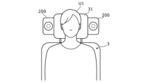
従来、自動車、航空機、又は列車等の移動体の座席に設置され、座席に着座したユーザに対して音声又は音楽等を再生するスピーカシステムが知られている。図1は、比較例のスピーカシステム200を示す概要図である。比較例のスピーカシステム200は、座席3のヘッドレスト31に設置されている。図1に示す例では、座席3に着座したユーザU1の左耳の近傍、及び右耳の近傍にそれぞれ比較例のスピーカシステム200が設置されている。 (Findings that formed the basis of this disclosure)
2. Description of the Related Art Conventionally, speaker systems are known that are installed in seats of moving objects such as automobiles, airplanes, or trains, and that reproduce audio, music, etc. to users seated in the seats. FIG. 1 is a schematic diagram showing aspeaker system 200 of a comparative example. The speaker system 200 of the comparative example is installed on the headrest 31 of the seat 3. In the example shown in FIG. 1, the speaker system 200 of the comparative example is installed near the left ear and near the right ear of the user U1 seated on the seat 3, respectively.
従来、自動車、航空機、又は列車等の移動体の座席に設置され、座席に着座したユーザに対して音声又は音楽等を再生するスピーカシステムが知られている。図1は、比較例のスピーカシステム200を示す概要図である。比較例のスピーカシステム200は、座席3のヘッドレスト31に設置されている。図1に示す例では、座席3に着座したユーザU1の左耳の近傍、及び右耳の近傍にそれぞれ比較例のスピーカシステム200が設置されている。 (Findings that formed the basis of this disclosure)
2. Description of the Related Art Conventionally, speaker systems are known that are installed in seats of moving objects such as automobiles, airplanes, or trains, and that reproduce audio, music, etc. to users seated in the seats. FIG. 1 is a schematic diagram showing a
ここで、比較例のスピーカシステム200では、スピーカから発せられる音波の指向性が、スピーカの正面方向に対して一様である。このため、比較例のスピーカシステム200では、スピーカで再生される音声又は音楽等が、座席3の隣りの座席に着座する人、及び座席3の後方に位置する座席に着座する人へと漏れやすい。つまり、比較例のスピーカシステム200では、対象となるユーザU1以外に音が漏れやすい、という課題がある。
Here, in the speaker system 200 of the comparative example, the directivity of the sound waves emitted from the speaker is uniform in the front direction of the speaker. Therefore, in the speaker system 200 of the comparative example, the sound or music played by the speaker is likely to leak to the person sitting in the seat next to seat 3 and the person sitting in the seat located behind seat 3. . In other words, the speaker system 200 of the comparative example has a problem in that sound tends to leak to users other than the target user U1.
本開示では、上記に鑑みて、音響レンズの構造を工夫することにより、音波の指向性を制御しやすくすることで、対象となるユーザU1以外に漏れる音を抑制しやすい音響レンズ等を提供することを目的とする。
In view of the above, the present disclosure provides an acoustic lens, etc. that easily suppresses sound leaking to users other than the target user U1 by making it easier to control the directivity of sound waves by devising the structure of the acoustic lens. The purpose is to
より具体的には、本開示の第1の態様に係る音響レンズは、スピーカから発せられる音波の進行方向において間隔を空けて並ぶ複数の第1仕切り板を備える。複数の第1仕切り板の各々は、音波が通過する複数の孔を有している。複数の第1仕切り板は、それぞれ第1方向の長さが互いに異なっている。
More specifically, the acoustic lens according to the first aspect of the present disclosure includes a plurality of first partition plates arranged at intervals in a traveling direction of sound waves emitted from a speaker. Each of the plurality of first partition plates has a plurality of holes through which sound waves pass. The plurality of first partition plates have different lengths in the first direction.
これによれば、第1方向において音波が通過する孔の多寡に応じて音波の通過する経路の長さを調整することができるので、音波の指向性を制御しやすい、という利点がある。
According to this, since the length of the path through which the sound waves pass can be adjusted depending on the number of holes through which the sound waves pass in the first direction, there is an advantage that the directivity of the sound waves can be easily controlled.
また、例えば、本開示の第2の態様に係る音響レンズでは、第1の態様において、複数の第1仕切り板は、第1方向の一方から他方に向かうにつれて音波の進行方向において重なる数が少なくなるように配置されている。
Furthermore, for example, in the acoustic lens according to the second aspect of the present disclosure, in the first aspect, the number of the plurality of first partition plates that overlap in the traveling direction of the sound wave decreases from one side to the other in the first direction. It is arranged so that
これによれば、第1方向のいずれの側に音波の指向性をもたせるかを制御しやすくなる、という利点がある。
According to this, there is an advantage that it becomes easier to control which side in the first direction the sound waves are to have directivity.
また、例えば、本開示の第3の態様に係る音響レンズは、第1又は第2の態様において、音波の進行方向において複数の第1仕切り板と重なっており、かつ、間隔を空けて並ぶ複数の第2仕切り板を更に備える。複数の第2仕切り板の各々は、音波が通過する複数の孔を有している。複数の第2仕切り板は、それぞれ第1方向と交差する第2方向の長さが互いに異なっている。
Further, for example, in the first or second aspect, the acoustic lens according to the third aspect of the present disclosure overlaps with the plurality of first partition plates in the propagation direction of the sound wave, and has a plurality of first partition plates arranged at intervals. It further includes a second partition plate. Each of the plurality of second partition plates has a plurality of holes through which sound waves pass. The plurality of second partition plates have different lengths in the second direction intersecting the first direction.
これによれば、複数の第1仕切り板により音波の第1方向における指向性を制御し、かつ、複数の第2仕切り板により音波の第2方向における指向性を制御するので、互いに交差する2方向の各々で音波の指向性を制御しやすい、という利点がある。
According to this, the directivity of the sound waves in the first direction is controlled by the plurality of first partition plates, and the directivity of the sound waves in the second direction is controlled by the plurality of second partition plates. This has the advantage that the directivity of the sound waves can be easily controlled in each direction.
また、例えば、本開示の第4の態様に係る音響レンズでは、第3の態様において、複数の第2仕切り板は、第2方向の中央から離れるにつれて音波の進行方向において重なる数が少なくなるように配置されている。
Further, for example, in the acoustic lens according to the fourth aspect of the present disclosure, in the third aspect, the plurality of second partition plates are such that the number of the second partition plates that overlap in the traveling direction of the sound wave decreases as the distance from the center in the second direction increases. It is located in
これによれば、第2方向の中央側に音波の指向性をもたせやすくなる、という利点がある。
According to this, there is an advantage that the directivity of the sound waves can be easily imparted to the center side in the second direction.
また、例えば、本開示の第5の態様に係る音響レンズでは、第3又は第4の態様において、第1方向及び第2方向は、互いに直交している。
Furthermore, for example, in the acoustic lens according to the fifth aspect of the present disclosure, the first direction and the second direction are orthogonal to each other in the third or fourth aspect.
これによれば、例えば第1方向を水平方向、第2方向を鉛直方向とすれば、水平方向及び鉛直方向の各々で音波の指向性を制御しやすい、という利点がある。
According to this, for example, if the first direction is the horizontal direction and the second direction is the vertical direction, there is an advantage that the directivity of the sound waves can be easily controlled in each of the horizontal direction and the vertical direction.
また、例えば、本開示の第6の態様に係る音響レンズでは、第1~第5のいずれか1つの態様において、複数の孔は、音波の進行方向において、スピーカから離れるにつれて直径が小さくなっている。
Further, for example, in the acoustic lens according to the sixth aspect of the present disclosure, in any one of the first to fifth aspects, the diameter of the plurality of holes becomes smaller as the distance from the speaker increases in the direction of propagation of the sound wave. There is.
これによれば、複数の孔の各々の直径が同じである場合と比較して、音波の通過する経路の長さが、通過する孔の数が多ければ多い程、より長くなるので、音波の指向性が鋭くなりやすい、という利点がある。
According to this, the length of the path through which the sound wave passes becomes longer as the number of holes through which the sound wave passes increases, compared to the case where the diameters of each of the multiple holes are the same. It has the advantage that the directivity tends to become sharper.
また、例えば、本開示の第7の態様に係る音響レンズでは、第1~第6のいずれか1つの態様において、複数の孔は、少なくとも一部が音波の進行方向において互いに重なり合っていない。
Furthermore, for example, in the acoustic lens according to the seventh aspect of the present disclosure, in any one of the first to sixth aspects, at least some of the holes do not overlap each other in the direction of propagation of the sound wave.
これによれば、複数の孔がいずれも音波の進行方向において互いに重なり合っている場合と比較して、音波が通過する経路を長くすることができるので、音波の指向性が鋭くなりやすい、という利点がある。
According to this, compared to the case where multiple holes all overlap each other in the direction of propagation of sound waves, the path through which the sound waves pass can be made longer, so the directivity of the sound waves tends to become sharper, which is an advantage. There is.
また、例えば、本開示の第8の態様に係るスピーカシステムは、第1~第7のいずれか1つの態様の音響レンズと、音響レンズに対して音波を発するスピーカと、を備える。
Furthermore, for example, a speaker system according to an eighth aspect of the present disclosure includes the acoustic lens according to any one of the first to seventh aspects, and a speaker that emits sound waves to the acoustic lens.
これによれば、上記の音響レンズと同様の効果を奏することができる、という利点がある。
According to this, there is an advantage that the same effect as the above-mentioned acoustic lens can be achieved.
以下、実施の形態について、図面を参照しながら具体的に説明する。なお、以下で説明する実施の形態は、いずれも包括的又は具体的な例を示すものである。以下の実施の形態で示される数値、形状、材料、構成要素、構成要素の配置位置及び接続形態、ステップ、又はステップの順序等は、一例であり、本開示を限定する主旨ではない。また、平行又は直交等の幾何学的な表現を用いる場合があるが、これらの表現は、数学的な厳密さを示すものではなく、実質的に許容される誤差又はずれ等が含まれる。例えば、以下の説明において、互いに交差する2方向が為す角度が90度±1~5%であれば、これらの2方向は直交している、と言える。また、同時又は同一等の表現も、実質的に許容される範囲を含んでいる。
Hereinafter, embodiments will be specifically described with reference to the drawings. Note that the embodiments described below are all inclusive or specific examples. Numerical values, shapes, materials, constituent elements, arrangement positions and connection forms of constituent elements, steps, or order of steps, etc. shown in the following embodiments are merely examples, and do not limit the present disclosure. Further, although geometric expressions such as parallel or perpendicular are sometimes used, these expressions do not indicate mathematical rigor and include substantially permissible errors or deviations. For example, in the following description, if the angle formed by two directions that intersect with each other is 90 degrees ±1 to 5%, it can be said that these two directions are orthogonal. In addition, expressions such as "simultaneous" or "same" also include a substantially permissible range.
また、以下の実施の形態における構成要素のうち、独立請求項に記載されていない構成要素については、任意の構成要素として説明される。なお、各図は模式図であり、必ずしも厳密に図示されたものではない。また、各図において、実質的に同一の構成に対しては同一の符号を付し、重複する説明は省略又は簡略化される場合がある。
Further, among the constituent elements in the following embodiments, constituent elements that are not described in the independent claims will be described as arbitrary constituent elements. Note that each figure is a schematic diagram and is not necessarily strictly illustrated. Further, in each figure, substantially the same configurations are denoted by the same reference numerals, and overlapping explanations may be omitted or simplified.
(実施の形態)
[1.構成]
以下、実施の形態に係る音響レンズ1、及び音響レンズ1を備えたスピーカシステム100について説明する。図2は、実施の形態に係る音響レンズ1を備えたスピーカシステム100の使用事例を示す概要図である。図2では、スピーカ2の図示を省略している。図3は、実施の形態に係る音響レンズ1の構成を示す概要図である。図4は、実施の形態に係る音響レンズ1の指向性の説明図である。 (Embodiment)
[1. composition]
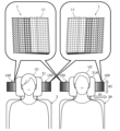
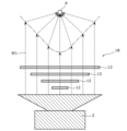
Hereinafter, anacoustic lens 1 according to an embodiment and a speaker system 100 including the acoustic lens 1 will be described. FIG. 2 is a schematic diagram showing an example of use of the speaker system 100 including the acoustic lens 1 according to the embodiment. In FIG. 2, illustration of the speaker 2 is omitted. FIG. 3 is a schematic diagram showing the configuration of the acoustic lens 1 according to the embodiment. FIG. 4 is an explanatory diagram of the directivity of the acoustic lens 1 according to the embodiment.
[1.構成]
以下、実施の形態に係る音響レンズ1、及び音響レンズ1を備えたスピーカシステム100について説明する。図2は、実施の形態に係る音響レンズ1を備えたスピーカシステム100の使用事例を示す概要図である。図2では、スピーカ2の図示を省略している。図3は、実施の形態に係る音響レンズ1の構成を示す概要図である。図4は、実施の形態に係る音響レンズ1の指向性の説明図である。 (Embodiment)
[1. composition]
Hereinafter, an
スピーカシステム100は、図2に示すように、音響レンズ1と、スピーカ2(図4参照)と、を備えている。スピーカシステム100は、スピーカ2から発せられて音響レンズ1を介して放射される音波W1(図4参照)を、対象となるユーザU1に聴かせるためのシステムである。
As shown in FIG. 2, the speaker system 100 includes an acoustic lens 1 and a speaker 2 (see FIG. 4). The speaker system 100 is a system for making a target user U1 listen to sound waves W1 (see FIG. 4) emitted from the speaker 2 and radiated through the acoustic lens 1.
実施の形態では、スピーカシステム100は、自動車等の移動体の座席3,3Aに設置されている。以下では、座席3は自動車の運転席であり、座席3Aは自動車の助手席であることとして説明する。座席3,3Aは、自動車の前側において、自動車の左右方向(水平方向)に並んでいる。以下では、特に断りの無い限り、自動車の左右方向(水平方向)を「第1方向d1」として説明する。また、以下では、特に断りの無い限り、自動車の高さ方向(鉛直方向)を「第2方向d2」として説明する。
In the embodiment, the speaker system 100 is installed in seats 3 and 3A of a moving body such as a car. In the following explanation, it is assumed that the seat 3 is the driver's seat of the automobile, and the seat 3A is the passenger seat of the automobile. The seats 3 and 3A are lined up in the left-right direction (horizontal direction) of the vehicle on the front side of the vehicle. In the following description, the left-right direction (horizontal direction) of the vehicle will be referred to as a "first direction d1" unless otherwise specified. Further, in the following description, unless otherwise specified, the height direction (vertical direction) of the vehicle will be referred to as a "second direction d2."
スピーカシステム100は、座席3のヘッドレスト31の第1方向d1における両端にそれぞれ設置されている。つまり、座席3に着座したユーザU1の左耳の近傍と、右耳の近傍とにそれぞれスピーカシステム100が設置されている。また、スピーカシステム100は、座席3Aのヘッドレスト31Aの第1方向d1における両端にそれぞれ設置されている。つまり、座席3Aに着座したユーザU2の左耳の近傍と、右耳の近傍とにそれぞれスピーカシステム100が設置されている。
The speaker system 100 is installed at both ends of the headrest 31 of the seat 3 in the first direction d1. That is, the speaker system 100 is installed near the left ear and near the right ear of the user U1 seated on the seat 3, respectively. Further, the speaker system 100 is installed at both ends of the headrest 31A of the seat 3A in the first direction d1. That is, the speaker system 100 is installed near the left ear and near the right ear of the user U2 seated on the seat 3A.
スピーカ2は、音声信号等の電気信号を振動板の振動に変換することで、音波W1を出力する装置である。スピーカ2を構成する振動板、磁気回路、又はフレーム等の大きさ、形状、又は構造は、特に限定されない。実施の形態では、スピーカ2は、コーン形状の振動板を備えた動電型のスピーカである。スピーカ2は、音響レンズ1に対して音波W1を発する。これにより、スピーカ2から発せられた音波W1は、音響レンズ1を通過して外部(大気)へと放射される。
The speaker 2 is a device that outputs a sound wave W1 by converting an electrical signal such as an audio signal into vibration of a diaphragm. The size, shape, or structure of the diaphragm, magnetic circuit, frame, etc. that constitute the speaker 2 is not particularly limited. In the embodiment, the speaker 2 is an electrodynamic speaker equipped with a cone-shaped diaphragm. The speaker 2 emits a sound wave W1 to the acoustic lens 1. Thereby, the sound wave W1 emitted from the speaker 2 passes through the acoustic lens 1 and is radiated to the outside (atmosphere).
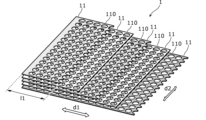
音響レンズ1は、図3に示すように、複数(ここでは、5つ)の第1仕切り板11を備えている。各第1仕切り板11は、平板状であって、それ自体が振動しにくい部材である。各第1仕切り板11を構成する材料は、例えば木材、樹脂、金属、又はセラミックス等であり、特に限定されない。
As shown in FIG. 3, the acoustic lens 1 includes a plurality (here, five) of first partition plates 11. Each first partition plate 11 has a flat plate shape, and is a member that itself does not easily vibrate. The material constituting each first partition plate 11 is, for example, wood, resin, metal, ceramics, or the like, and is not particularly limited.
複数の第1仕切り板11は、図3及び図4に示すように、スピーカ2から発せられる音波W1の進行方向において間隔を空けて並ぶように配置されている。なお、図示していないが、各第1仕切り板11は、例えば各第1仕切り板11の外周縁に設けられた枠状の部材により支持されてもよいし、隣り合う第1仕切り板11の間に設けられたスペーサにより支持されてもよい。
As shown in FIGS. 3 and 4, the plurality of first partition plates 11 are arranged at intervals in the traveling direction of the sound wave W1 emitted from the speaker 2. Although not shown, each first partition plate 11 may be supported, for example, by a frame-shaped member provided on the outer periphery of each first partition plate 11, or by supporting the adjacent first partition plates 11. It may be supported by a spacer provided therebetween.
ここで、「音波W1の進行方向」とは、スピーカ2から発せられる音波W1の進行方向であって、音響レンズ1を通過している音波W1の進行方向ではない。実施の形態では、音波W1の進行方向は、第1方向d1及び第2方向d2の両方に直交する方向に相当する。
Here, "the traveling direction of the sound wave W1" is the traveling direction of the sound wave W1 emitted from the speaker 2, and is not the traveling direction of the sound wave W1 passing through the acoustic lens 1. In the embodiment, the traveling direction of the sound wave W1 corresponds to a direction perpendicular to both the first direction d1 and the second direction d2.
ここで、既に述べたように、実施の形態では、第1方向d1は水平方向であり、第2方向d2は鉛直方向である。したがって、実施の形態では、第1方向d1及び第2方向d2は、互いに直交している。なお、第1方向d1及び第2方向d2は、互いに交差していればよく、互いに直交していなくてもよい。
Here, as already mentioned, in the embodiment, the first direction d1 is the horizontal direction, and the second direction d2 is the vertical direction. Therefore, in the embodiment, the first direction d1 and the second direction d2 are orthogonal to each other. Note that the first direction d1 and the second direction d2 only need to intersect with each other, and do not need to be orthogonal to each other.
複数の第1仕切り板11の各々は、図3に示すように、音波W1が通過する複数の孔110を有している。実施の形態では、孔110は、平面視で(つまり、音波W1の進行方向から見て)円形状であって、第1仕切り板11を厚さ方向(つまり、音波W1の進行方向)に貫通している。また、実施の形態では、各第1仕切り板11において、複数の孔110は、第1方向d1にm(mは自然数)個、第2方向d2にn(nは自然数)個が並ぶ行列をなすように設けられている。
As shown in FIG. 3, each of the plurality of first partition plates 11 has a plurality of holes 110 through which the sound waves W1 pass. In the embodiment, the hole 110 has a circular shape in a plan view (that is, viewed from the direction of propagation of the sound wave W1), and penetrates the first partition plate 11 in the thickness direction (that is, the direction of propagation of the sound wave W1). are doing. In the embodiment, in each first partition plate 11, the plurality of holes 110 are arranged in a matrix in which m (m is a natural number) holes are arranged in the first direction d1 and n (where n is a natural number) in the second direction d2. It is set up so that
ここで、「m」は、第1仕切り板11の第1方向d1の長さに応じて変化し、「n」は、第1仕切り板11の第2方向d2の長さに応じて変化し得る。実施の形態では、後述するように、各第1仕切り板11の第1方向d1の長さは互いに異なっているので、各第1仕切り板11において第1方向d1に並ぶ孔110の数は互いに異なっている。一方、実施の形態では、各第1仕切り板11の第2方向d2の長さはいずれも同じであるので、各第1仕切り板11において第2方向d2に並ぶ孔110の数はいずれも同じである。
Here, "m" changes according to the length of the first partition plate 11 in the first direction d1, and "n" changes according to the length of the first partition plate 11 in the second direction d2. obtain. In the embodiment, as will be described later, since the lengths of the first partition plates 11 in the first direction d1 are different from each other, the number of holes 110 lined up in the first direction d1 in each of the first partition plates 11 is different from each other. It's different. On the other hand, in the embodiment, since the lengths in the second direction d2 of each first partition plate 11 are the same, the number of holes 110 lined up in the second direction d2 in each first partition plate 11 is the same. It is.
実施の形態では、図3に示すように、複数の第1仕切り板11は、それぞれ第1方向d1の長さl1が互いに異なっている。ここでは、第1方向d1は、音波W1の指向性を制御する方向である。そして、複数の第1仕切り板11は、第1方向d1の一方(図3における左側)から他方(図3における右側)に向かうにつれて音波W1の進行方向において重なる数が少なくなるように配置されている。言い換えれば、音波W1の第1方向d1において指向性をもたせたい側ほど、音波W1の進行方向において重なる数が少なくなるように、複数の第1仕切り板11が配置されている。さらに言い換えれば、複数の第1仕切り板11は、音波W1の進行方向における上方から下方に向かうにつれて、第1方向d1の長さl1が長くなるように配置されている。つまり、複数の第1仕切り板11のうち、音波W1の進行方向において最も上方に位置する第1仕切り板11の第1方向d1の長さl1が最も短く、最も下方に位置する第1仕切り板11の第1方向d1の長さl1が最も長くなっている。
In the embodiment, as shown in FIG. 3, the plurality of first partition plates 11 have different lengths l1 in the first direction d1. Here, the first direction d1 is a direction for controlling the directivity of the sound wave W1. The plurality of first partition plates 11 are arranged such that the number of the first partition plates 11 that overlap in the traveling direction of the sound wave W1 decreases from one side (the left side in FIG. 3) to the other side (the right side in FIG. 3) in the first direction d1. There is. In other words, the plurality of first partition plates 11 are arranged such that the side on which the sound wave W1 is desired to have more directivity in the first direction d1 has a smaller number of overlapping plates in the traveling direction of the sound wave W1. In other words, the plurality of first partition plates 11 are arranged such that the length l1 in the first direction d1 increases from the top to the bottom in the traveling direction of the sound wave W1. That is, among the plurality of first partition plates 11, the first partition plate 11 located at the uppermost position in the traveling direction of the sound wave W1 has the shortest length l1 in the first direction, and the first partition plate located at the lowermost position has the shortest length l1. The length l1 in the first direction d1 of No. 11 is the longest.
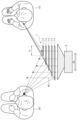
ここで、音響レンズ1による、音波W1の第1方向d1における指向性の制御について図4を用いて説明する。図4では、各孔110の図示を省略している。また、図4において、各第1仕切り板11を通過する音波W1は、実際には各孔110を通過している。図4に示すように、音波W1は、各第1仕切り板11の各孔110を通過して外部(大気)へと放射される。
Here, control of the directivity of the sound wave W1 in the first direction d1 by the acoustic lens 1 will be explained using FIG. 4. In FIG. 4, illustration of each hole 110 is omitted. Further, in FIG. 4, the sound waves W1 passing through each first partition plate 11 actually pass through each hole 110. As shown in FIG. 4, the sound wave W1 passes through each hole 110 of each first partition plate 11 and is radiated to the outside (atmosphere).
ここで、図4に示すように、音響レンズ1では、音波W1の通過する経路の長さを変えることで、第1方向d1における指向性を制御している。
Here, as shown in FIG. 4, in the acoustic lens 1, the directivity in the first direction d1 is controlled by changing the length of the path through which the sound wave W1 passes.
具体的には、スピーカ2から放射されて座席3Aに着座したユーザU2の耳に到達する音波W1は、一点鎖線で示されるように、第1仕切り板11の重なりが多いほど、つまり第1方向d1における一方(図4における右側)に近いほど、音波W1の経路が長くなる。このため、第1方向d1における一方での音波W1の経路の長さと、第1仕切り板11の重なりが少ない側、つまり第1方向d1における他方(図4における左側)での音波W1の経路の長さとの差が大きくなり、ユーザU2の耳に到達する音波W1の到達時間の差が大きく、音波W1の打消しが大きくなる。
Specifically, as shown by the dashed line, the more the first partition plates 11 overlap, the more the sound wave W1 emitted from the speaker 2 and reaching the ear of the user U2 seated on the seat 3A, the more the sound wave W1 is emitted from the speaker 2 and reaches the ear of the user U2 seated on the seat 3A. The closer to one side (the right side in FIG. 4) in d1, the longer the path of the sound wave W1 becomes. Therefore, the length of the path of the sound wave W1 on one side in the first direction d1 and the path of the sound wave W1 on the other side (the left side in FIG. 4) in the first direction d1, which is the side where the first partition plate 11 overlaps less, are The difference in the arrival time of the sound wave W1 to the ear of the user U2 becomes large, and the cancellation of the sound wave W1 becomes large.
これに対して、スピーカ2から放射されて座席3に着座したユーザU1の耳に到達する音波W1は、破線で示されるように、ユーザU1が第1仕切り板11の重なりが多い第1方向d1における一方側に位置するため、第1仕切り板11の重なりが音波W1の経路に影響を殆ど与えない。このため、第1方向d1における一方での音波W1の経路の長さと、第1方向d1における他方での音波W1の経路の長さとの差が殆どないため、ユーザU1の耳に到達する音波W1の到達時間の差が小さく、音波W1の打消しの影響が少ない。
On the other hand, the sound wave W1 emitted from the speaker 2 and reaching the ear of the user U1 seated on the seat 3 is transmitted in the first direction d1 where the user U1 has more overlap with the first partition plate 11, as shown by the broken line. Since the first partition plate 11 is located on one side of the first partition plate 11, the overlapping of the first partition plates 11 hardly affects the path of the sound wave W1. Therefore, since there is almost no difference between the length of the path of the sound wave W1 on one side in the first direction d1 and the length of the path of the sound wave W1 on the other side in the first direction d1, the sound wave W1 reaching the ear of the user U1 The difference in arrival time is small, and the influence of cancellation of the sound wave W1 is small.
したがって、ユーザU1の耳に到達する音波W1の音圧レベルに対して、ユーザU2の耳に到達する音波W1の音圧レベルが抑制されるため、第1方向d1における一方に偏向した指向性となる。
Therefore, the sound pressure level of the sound wave W1 reaching the ear of the user U2 is suppressed relative to the sound pressure level of the sound wave W1 reaching the ear of the user U1. Become.
[2.利点]
以下、実施の形態に係る音響レンズ1及びスピーカシステム100の利点について説明する。上述のように、実施の形態に係る音響レンズ1では、音波W1の進行方向において間隔を空けて並ぶ複数の第1仕切り板11を、それぞれ第1方向d1の長さを互いに異ならせている。このため、実施の形態に係る音響レンズ1では、音波W1が通過する孔110の多寡に応じて音波W1の通過する経路の長さを調整することができるので、音波W1の指向性(ここでは、音波W1の第1方向d1における指向性)を制御しやすい、という利点がある。 [2. advantage]
Advantages of theacoustic lens 1 and speaker system 100 according to the embodiment will be described below. As described above, in the acoustic lens 1 according to the embodiment, the plurality of first partition plates 11 arranged at intervals in the traveling direction of the sound wave W1 are made to have different lengths in the first direction d1. Therefore, in the acoustic lens 1 according to the embodiment, the length of the path through which the sound wave W1 passes can be adjusted depending on the number of holes 110 through which the sound wave W1 passes. , the directivity of the sound wave W1 in the first direction d1) can be easily controlled.
以下、実施の形態に係る音響レンズ1及びスピーカシステム100の利点について説明する。上述のように、実施の形態に係る音響レンズ1では、音波W1の進行方向において間隔を空けて並ぶ複数の第1仕切り板11を、それぞれ第1方向d1の長さを互いに異ならせている。このため、実施の形態に係る音響レンズ1では、音波W1が通過する孔110の多寡に応じて音波W1の通過する経路の長さを調整することができるので、音波W1の指向性(ここでは、音波W1の第1方向d1における指向性)を制御しやすい、という利点がある。 [2. advantage]
Advantages of the
実施の形態では、第1方向d1を水平方向として、音響レンズ1は、音波W1の水平方向の指向性を制御することが可能である。このため、実施の形態に係る音響レンズ1、及び音響レンズ1を用いたスピーカシステム100は、比較例のスピーカシステム200が有していた課題を解消し得る。
In the embodiment, the acoustic lens 1 can control the horizontal directivity of the sound wave W1, with the first direction d1 being the horizontal direction. Therefore, the acoustic lens 1 according to the embodiment and the speaker system 100 using the acoustic lens 1 can solve the problems that the speaker system 200 of the comparative example had.
例えば、図2に示すように、座席3に着座したユーザU1の左耳の近傍、及び右耳の近傍にそれぞれスピーカシステム100を配置し、かつ、音波W1が水平方向(第1方向d1)においてユーザU1に偏向した指向性となるように音響レンズ1を配置する。この場合、スピーカ2が発する音波W1が、音響レンズ1を介して水平方向においてユーザU1に偏向した指向性となるように放射されるので、座席3の隣りの座席3Aに着座するユーザU2へと音が漏れにくい。
For example, as shown in FIG. 2, the speaker system 100 is arranged near the left ear and the right ear of the user U1 seated on the seat 3, and the sound wave W1 is arranged in the horizontal direction (first direction d1). The acoustic lens 1 is arranged so that the directivity is biased toward the user U1. In this case, the sound wave W1 emitted by the speaker 2 is radiated through the acoustic lens 1 so as to have a directionality deflected toward the user U1 in the horizontal direction, so that the sound wave W1 is directed toward the user U2 who is seated on the seat 3A next to the seat 3. Sound doesn't easily leak out.
同様に、座席3の隣りの座席3Aに着座したユーザU2の左耳の近傍、及び右耳の近傍にそれぞれスピーカシステム100を配置し、かつ、音波W1が水平方向(第1方向d1)においてユーザU2に偏向した指向性となるように音響レンズ1を配置する。この場合、スピーカ2が発する音波W1が、音響レンズ1を介して水平方向においてユーザU2に偏向した指向性となるように放射されるので、座席3に着座するユーザU1へと音が漏れにくい。
Similarly, the speaker system 100 is placed near the left ear and near the right ear of the user U2 who is seated on the seat 3A next to the seat 3, and the sound wave W1 is directed toward the user U2 in the horizontal direction (first direction d1). The acoustic lens 1 is arranged so that the directivity is deflected toward U2. In this case, the sound wave W1 emitted by the speaker 2 is radiated through the acoustic lens 1 so as to have a directionality deflected toward the user U2 in the horizontal direction, so that the sound is less likely to leak to the user U1 seated on the seat 3.
上述のように、実施の形態に係る音響レンズ1、及び音響レンズ1を用いたスピーカシステム100では、対象となるユーザU1(又はユーザU2)以外に漏れる音を抑制しやすい、という利点がある。
As described above, the acoustic lens 1 according to the embodiment and the speaker system 100 using the acoustic lens 1 have the advantage that it is easy to suppress sound leaking to users other than the target user U1 (or user U2).
(その他の実施の形態)
以上、実施の形態について説明したが、本開示は、上記の実施の形態に限定されるものではない。 (Other embodiments)
Although the embodiments have been described above, the present disclosure is not limited to the above embodiments.
以上、実施の形態について説明したが、本開示は、上記の実施の形態に限定されるものではない。 (Other embodiments)
Although the embodiments have been described above, the present disclosure is not limited to the above embodiments.
<第1変形例>
図5は、実施の形態の第1変形例に係る音響レンズ1Aの構成を示す概要図である。第1変形例に係る音響レンズ1Aは、複数の孔110が、音波W1の進行方向(言い換えれば、第1仕切り板11の厚さ方向)において、スピーカ2から離れるにつれて直径R1が小さくなっている点で、実施の形態に係る音響レンズ1と相違する。 <First modification example>
FIG. 5 is a schematic diagram showing the configuration of anacoustic lens 1A according to a first modification of the embodiment. In the acoustic lens 1A according to the first modification, the diameter R1 of the plurality of holes 110 becomes smaller as the distance from the speaker 2 increases in the traveling direction of the sound wave W1 (in other words, the thickness direction of the first partition plate 11). This is different from the acoustic lens 1 according to the embodiment.
図5は、実施の形態の第1変形例に係る音響レンズ1Aの構成を示す概要図である。第1変形例に係る音響レンズ1Aは、複数の孔110が、音波W1の進行方向(言い換えれば、第1仕切り板11の厚さ方向)において、スピーカ2から離れるにつれて直径R1が小さくなっている点で、実施の形態に係る音響レンズ1と相違する。 <First modification example>
FIG. 5 is a schematic diagram showing the configuration of an
具体的には、音波W1の進行方向において最も下方に位置する第1仕切り板11が有する各孔110の直径R1が最も大きく、最も上方に位置する第1仕切り板11が有する各孔110の直径R1が最も小さくなっている。ここで、任意の第1仕切り板11において、第1仕切り板11の面積に対する複数の孔110の総面積の割合を開口率と定義する。すると、第1変形例に係る音響レンズ1Aでは、複数の第1仕切り板11は、それぞれ音波W1の進行方向において、スピーカ2から離れるにつれて開口率が小さくなっている、と言える。
Specifically, in the traveling direction of the sound wave W1, the diameter R1 of each hole 110 of the first partition plate 11 located at the lowest position is the largest, and the diameter R1 of each hole 110 of the first partition plate 11 located at the highest position is the largest. R1 is the smallest. Here, in any first partition plate 11, the ratio of the total area of the plurality of holes 110 to the area of the first partition plate 11 is defined as the aperture ratio. Then, in the acoustic lens 1A according to the first modification, it can be said that the aperture ratio of each of the plurality of first partition plates 11 becomes smaller as the distance from the speaker 2 increases in the traveling direction of the sound wave W1.
上述のように、第1変形例に係る音響レンズ1Aでは、複数の第1仕切り板11が、それぞれ音波W1の進行方向においてスピーカ2から離れるにつれて開口率が小さくなっている。このため、第1変形例に係る音響レンズ1Aでは、音波W1の通過する経路の長さは、通過する孔110の数が多ければ多い程、より長くなる。したがって、第1変形例に係る音響レンズ1Aでは、実施の形態に係る音響レンズ1と比較して、音波W1が第1方向d1における一方(図5における左側)により偏向した指向性となるように制御されることになり、音波W1の指向性が鋭くなりやすい、という利点がある。
As described above, in the acoustic lens 1A according to the first modification, the aperture ratio of each of the plurality of first partition plates 11 becomes smaller as the distance from the speaker 2 increases in the traveling direction of the sound wave W1. Therefore, in the acoustic lens 1A according to the first modification, the length of the path through which the sound wave W1 increases as the number of holes 110 through which it passes increases. Therefore, in the acoustic lens 1A according to the first modification, compared to the acoustic lens 1 according to the embodiment, the sound wave W1 has a directivity that is deflected to one side (the left side in FIG. 5) in the first direction d1. This has the advantage that the directivity of the sound wave W1 tends to become sharper.
<第2変形例>
図6は、実施の形態の第2変形例に係る音響レンズ1Bの構成を示す概要図である。第2変形例に係る音響レンズ1Bは、複数の第2仕切り板12を更に備えている点で、実施の形態に係る音響レンズ1と相違する。 <Second modification example>
FIG. 6 is a schematic diagram showing the configuration of anacoustic lens 1B according to a second modification of the embodiment. The acoustic lens 1B according to the second modification differs from the acoustic lens 1 according to the embodiment in that it further includes a plurality of second partition plates 12.
図6は、実施の形態の第2変形例に係る音響レンズ1Bの構成を示す概要図である。第2変形例に係る音響レンズ1Bは、複数の第2仕切り板12を更に備えている点で、実施の形態に係る音響レンズ1と相違する。 <Second modification example>
FIG. 6 is a schematic diagram showing the configuration of an
各第2仕切り板12は、平板状であって、それ自体が振動しにくい部材である。各第2仕切り板12を構成する材料は、例えば木材、樹脂、金属、又はセラミックス等であり、特に限定されない。複数の第2仕切り板12は、図6に示すように、音波W1の進行方向において複数の第1仕切り板11と重なっており、かつ、間隔を空けて並ぶように配置されている。具体的には、複数の第2仕切り板12は、音波W1の進行方向において、第1仕切り板11と第2仕切り板12とが交互に間隔を空けて並ぶように配置されている。なお、各第2仕切り板12は、各第1仕切り板11と同様に、図示しない枠状の部材又はスペーサにより支持されてもよい。
Each of the second partition plates 12 has a flat plate shape, and is a member that itself is difficult to vibrate. The material constituting each second partition plate 12 is, for example, wood, resin, metal, ceramics, or the like, and is not particularly limited. As shown in FIG. 6, the plurality of second partition plates 12 overlap with the plurality of first partition plates 11 in the traveling direction of the sound wave W1, and are arranged so as to be spaced apart from each other. Specifically, the plurality of second partition plates 12 are arranged such that the first partition plates 11 and the second partition plates 12 are alternately lined up at intervals in the traveling direction of the sound wave W1. Note that, like each first partition plate 11, each second partition plate 12 may be supported by a frame-shaped member or a spacer (not shown).
複数の第2仕切り板12の各々は、図6に示すように、音波W1が通過する複数の孔120を有している。なお、図6では、音波W1の進行方向(言い換えれば、第2仕切り板12の厚さ方向)において最も上方に位置する第2仕切り板12の複数の孔120のみを図示しており、他の第2仕切り板12の複数の孔120の図示は省略している。また、図6では、各第1仕切り板11の複数の孔110の図示を省略している。
As shown in FIG. 6, each of the plurality of second partition plates 12 has a plurality of holes 120 through which the sound waves W1 pass. In addition, in FIG. 6, only the plurality of holes 120 of the second partition plate 12 located at the uppermost position in the traveling direction of the sound wave W1 (in other words, the thickness direction of the second partition plate 12) are illustrated, and the other holes 120 are illustrated. Illustration of the plurality of holes 120 of the second partition plate 12 is omitted. Further, in FIG. 6, illustration of the plurality of holes 110 of each first partition plate 11 is omitted.
第2変形例では、孔120は、平面視で(つまり、音波W1の進行方向から見て)円形状であって、第2仕切り板12を厚さ方向(つまり、音波W1の進行方向)に貫通している。また、第2変形例では、各第2仕切り板12において、複数の孔120は、第1方向d1にp(pは自然数)個、第2方向d2にq(qは自然数)個が並ぶ行列をなすように設けられている。
In the second modification, the hole 120 has a circular shape in a plan view (that is, when viewed from the traveling direction of the sound wave W1), and extends through the second partition plate 12 in the thickness direction (that is, in the traveling direction of the sound wave W1). Penetrating. In the second modification, in each second partition plate 12, the plurality of holes 120 are arranged in a matrix in which p (p is a natural number) holes are arranged in the first direction d1 and q (q is a natural number) holes are arranged in the second direction d2. It is set up so that
ここで、「p」は、第2仕切り板12の第1方向d1の長さに応じて変化し、「q」は、第2仕切り板12の第2方向d2の長さに応じて変化し得る。第2変形例では、後述するように、各第2仕切り板12の第1方向d1の長さ及び第2方向d2の長さはそれぞれ互いに異なっているので、各第2仕切り板12において第1方向d1に並ぶ孔120の数は互いに異なっており、第2方向d2に並ぶ孔120の数も互いに異なっている。
Here, "p" changes according to the length of the second partition plate 12 in the first direction d1, and "q" changes according to the length of the second partition plate 12 in the second direction d2. obtain. In the second modification, as will be described later, the lengths in the first direction d1 and the lengths in the second direction d2 of each of the second partition plates 12 are different from each other. The number of holes 120 lined up in the direction d1 is different from each other, and the number of holes 120 lined up in the second direction d2 is also different from each other.
第2変形例では、図6に示すように、複数の第2仕切り板12は、それぞれ第1方向d1の長さl1が互いに異なっている。また、複数の第2仕切り板12は、それぞれ第1方向d1と交差する第2方向d2の長さl2が互いに異なっている。ここで、第2方向d2は、第1方向d1と同様に、音波W1の指向性を制御する方向である。そして、複数の第2仕切り板12は、第2方向d2の中央から離れるにつれて音波W1の進行方向において重なる数が少なくなるように配置されている。言い換えれば、音波W1の第2方向d2において指向性をもたせたい側ほど、音波W1の進行方向において重なる数が多くなるように、複数の第2仕切り板12が配置されている。さらに言い換えれば、複数の第2仕切り板12は、音波W1の進行方向における上方から下方に向かうにつれて、第2方向d2の長さl2が短くなるように配置されている。つまり、複数の第2仕切り板12のうち、音波W1の進行方向において最も上方に位置する第2仕切り板12の第2方向d2の長さl2が最も長く、最も下方に位置する第2仕切り板12の第2方向d2の長さl2が最も短くなっている。
In the second modification, as shown in FIG. 6, the plurality of second partition plates 12 have different lengths l1 in the first direction d1. Further, the plurality of second partition plates 12 have different lengths l2 in the second direction d2 intersecting the first direction d1. Here, the second direction d2 is a direction for controlling the directivity of the sound wave W1, similar to the first direction d1. The plurality of second partition plates 12 are arranged such that the number of the second partition plates 12 that overlap in the traveling direction of the sound wave W1 decreases as the distance from the center in the second direction d2 decreases. In other words, the plurality of second partition plates 12 are arranged such that the side on which the sound wave W1 is desired to have directivity in the second direction d2 has a larger number of overlapping plates in the traveling direction of the sound wave W1. In other words, the plurality of second partition plates 12 are arranged such that the length l2 in the second direction d2 becomes shorter from the top to the bottom in the traveling direction of the sound wave W1. That is, among the plurality of second partition plates 12, the second partition plate 12 located at the uppermost position in the traveling direction of the sound wave W1 has the longest length l2 in the second direction, and the second partition plate located at the lowermost position has the longest length l2. The length l2 in the second direction d2 of No. 12 is the shortest.
ここで、第2変形例に係る音響レンズ1Bによる、音波W1の第2方向d2における指向性の制御について図7を用いて説明する。図7は、実施の形態の第2変形例に係る音響レンズ1Bの指向性の説明図である。図7では、各第1仕切り板11の図示、及び各第2仕切り板12の各孔120の図示を省略している。また、図7において、各第2仕切り板12を通過する音波W1は、実際には各第1仕切り板11の各孔110、及び各第2仕切り板12の各孔120を通過している。
Here, control of the directivity of the sound wave W1 in the second direction d2 by the acoustic lens 1B according to the second modification will be described using FIG. 7. FIG. 7 is an explanatory diagram of the directivity of the acoustic lens 1B according to the second modification of the embodiment. In FIG. 7, illustration of each first partition plate 11 and illustration of each hole 120 of each second partition plate 12 are omitted. Further, in FIG. 7, the sound waves W1 passing through each second partition plate 12 actually pass through each hole 110 of each first partition plate 11 and each hole 120 of each second partition plate 12.
ここで、図7に示すように、音響レンズ1Bでは、音波W1の通過する経路の長さを変えることで、第2方向d2における指向性を制御している。
Here, as shown in FIG. 7, in the acoustic lens 1B, the directivity in the second direction d2 is controlled by changing the length of the path through which the sound wave W1 passes.
具体的には、スピーカ2から放射された音波W1の通過する経路は、第2仕切り板12の重なりが多い第2方向d2における中央ほど長くなり、第2仕切り板12の重なりが少ない第2方向d2における端部(図7における右端及び左端)ほど短くなる。このため、音波W1の波面は、図7の一点鎖線で示すような凹状の波面と仮想的にみなすことができる。
Specifically, the path that the sound wave W1 emitted from the speaker 2 passes becomes longer in the middle in the second direction d2 where the second partition plates 12 overlap more, and in the second direction where the second partition plates 12 overlap less. The end portions at d2 (right end and left end in FIG. 7) become shorter. Therefore, the wavefront of the sound wave W1 can be virtually regarded as a concave wavefront as shown by the dashed line in FIG.
これにより、音響レンズ1Bは、あたかもパラボラアンテナで焦点に電波を集中させるように、仮想点pに音波W1を集中させるような効果を奏する。したがって、音響レンズ1Bの中心軸上にある仮想点pでの音圧レベルが高くなり、中心軸を外れた位置で音圧レベルが抑制されるので、第2方向d2における中央に偏向した指向性となる。上述のように、第2変形例に係る音響レンズ1Bでは、音波W1の進行方向において間隔を空けて並ぶ複数の第2仕切り板12を、それぞれ第2方向d2の長さを互いに異ならせることで、音波W1の指向性(ここでは、音波W1の第2方向d2における指向性)を制御しやすい、という利点がある。
Thereby, the acoustic lens 1B has the effect of concentrating the sound wave W1 on the virtual point p, just as a parabolic antenna concentrates radio waves on the focal point. Therefore, the sound pressure level at the virtual point p on the central axis of the acoustic lens 1B increases, and the sound pressure level is suppressed at positions off the central axis, so that the directivity is deflected toward the center in the second direction d2. becomes. As described above, in the acoustic lens 1B according to the second modification, the plurality of second partition plates 12 arranged at intervals in the traveling direction of the sound wave W1 are made to have different lengths in the second direction d2. , there is an advantage that the directivity of the sound wave W1 (here, the directivity of the sound wave W1 in the second direction d2) can be easily controlled.
第2変形例では、第2方向d2を鉛直方向として、音響レンズ1Bは、音波W1の鉛直方向の指向性を制御することが可能である。このため、第2変形例に係る音響レンズ1B、及び音響レンズ1Bを用いたスピーカシステム100は、比較例のスピーカシステム200が有していた課題を解消し得る。
In the second modification, the acoustic lens 1B can control the directivity of the sound wave W1 in the vertical direction, with the second direction d2 being the vertical direction. Therefore, the acoustic lens 1B according to the second modification and the speaker system 100 using the acoustic lens 1B can solve the problem that the speaker system 200 of the comparative example had.
例えば、図2に示す使用例と同様に、座席3に着座したユーザU1の左耳の近傍、及び右耳の近傍に、それぞれ音響レンズ1Bを用いたスピーカシステム100を配置する。この場合、スピーカ2が発する音波W1が、音響レンズ1Bを介して鉛直方向に拡散せずにユーザU1の正面に偏向した指向性となるように放射されるので、座席3の後方へと音波W1が回り込みにくく、座席3の後方に位置する座席に着座するユーザへと音が漏れにくい。
For example, similarly to the usage example shown in FIG. 2, the speaker system 100 using the acoustic lens 1B is placed near the left ear and near the right ear of the user U1 seated on the seat 3, respectively. In this case, the sound wave W1 emitted by the speaker 2 is not diffused in the vertical direction through the acoustic lens 1B, but is radiated with a directivity deflected toward the front of the user U1, so that the sound wave W1 is directed toward the rear of the seat 3. It is difficult for sound to go around, and the sound is difficult to leak to a user sitting on a seat located behind the seat 3.
なお、第2変形例に係る音響レンズ1Bでは、第1変形例と同様に、音波W1の進行方向において、スピーカ2から離れるにつれて各第1仕切り板11の開口率を小さくしてもよい。同様に、音波W1の進行方向において、スピーカ2から離れるにつれて各第2仕切り板12の開口率を小さくしてもよい。第2仕切り板12の開口率は、任意の第2仕切り板12において、第2仕切り板12の面積に対する複数の孔120の総面積の割合で定義される。この構成では、各第1仕切り板11及び各第2仕切り板12の開口率を変化させない場合と比較して、音波W1の指向性が鋭くなりやすい、という利点がある。
Note that in the acoustic lens 1B according to the second modification, the aperture ratio of each first partition plate 11 may be decreased as the distance from the speaker 2 increases in the traveling direction of the sound wave W1, similarly to the first modification. Similarly, the aperture ratio of each second partition plate 12 may be decreased as the distance from the speaker 2 increases in the traveling direction of the sound wave W1. The aperture ratio of the second partition plate 12 is defined as the ratio of the total area of the plurality of holes 120 to the area of the second partition plate 12 in any second partition plate 12. This configuration has an advantage in that the directivity of the sound wave W1 tends to become sharper than when the aperture ratio of each first partition plate 11 and each second partition plate 12 is not changed.
<第3変形例>
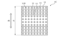
図8は、実施の形態の第3変形例に係る音響レンズ1Cの構成を示す概要図である。第3変形例に係る音響レンズ1Cは、第1方向d1を鉛直方向としており、かつ、第1方向d1における中央から離れるにつれて音波W1の進行方向において重なる数が少なくなるように配置されている点で、実施の形態に係る音響レンズ1と相違する。つまり、第3変形例に係る音響レンズ1Cは、音波W1の鉛直方向における指向性を主として制御するように構成されている点で、音波W1の水平方向における指向性を主として制御するように構成されている実施の形態に係る音響レンズ1と相違する。 <Third modification example>
FIG. 8 is a schematic diagram showing the configuration of anacoustic lens 1C according to a third modification of the embodiment. The acoustic lens 1C according to the third modification is arranged so that the first direction d1 is the vertical direction, and the number of overlapping waves in the traveling direction of the sound waves W1 decreases as the distance from the center in the first direction d1 increases. This is different from the acoustic lens 1 according to the embodiment. That is, the acoustic lens 1C according to the third modification is configured to mainly control the directivity of the sound wave W1 in the vertical direction, and is configured to mainly control the directivity of the sound wave W1 in the horizontal direction. This is different from the acoustic lens 1 according to the embodiment shown in FIG.
図8は、実施の形態の第3変形例に係る音響レンズ1Cの構成を示す概要図である。第3変形例に係る音響レンズ1Cは、第1方向d1を鉛直方向としており、かつ、第1方向d1における中央から離れるにつれて音波W1の進行方向において重なる数が少なくなるように配置されている点で、実施の形態に係る音響レンズ1と相違する。つまり、第3変形例に係る音響レンズ1Cは、音波W1の鉛直方向における指向性を主として制御するように構成されている点で、音波W1の水平方向における指向性を主として制御するように構成されている実施の形態に係る音響レンズ1と相違する。 <Third modification example>
FIG. 8 is a schematic diagram showing the configuration of an
具体的には、第3変形例では、図8に示すように、複数の第1仕切り板11は、それぞれ第1方向d1の長さl1が互いに異なっている。そして、複数の第1仕切り板11は、第1方向d1の中央から離れるにつれて音波W1の進行方向において重なる数が少なくなるように配置されている。言い換えれば、音波W1の第1方向d1において指向性をもたせたい側ほど、音波W1の進行方向において重なる数が多くなるように、複数の第1仕切り板11が配置されている。さらに言い換えれば、複数の第1仕切り板11は、音波W1の進行方向における上方から下方に向かうにつれて、第1方向d1の長さl1が長くなるように配置されている。つまり、複数の第1仕切り板11のうち、音波W1の進行方向において最も上方に位置する第1仕切り板11の第1方向d1の長さl1が最も短く、最も下方に位置する第1仕切り板11の第1方向d1の長さl1が最も長くなっている。
Specifically, in the third modification, as shown in FIG. 8, the plurality of first partition plates 11 have different lengths l1 in the first direction d1. The plurality of first partition plates 11 are arranged such that the number of the first partition plates 11 that overlap in the traveling direction of the sound wave W1 decreases as the distance from the center in the first direction d1 increases. In other words, the plurality of first partition plates 11 are arranged such that the side on which the sound wave W1 is desired to have directivity in the first direction d1 has a larger number of overlapping plates in the traveling direction of the sound wave W1. In other words, the plurality of first partition plates 11 are arranged such that the length l1 in the first direction d1 increases from the top to the bottom in the traveling direction of the sound wave W1. That is, among the plurality of first partition plates 11, the first partition plate 11 located at the uppermost position in the traveling direction of the sound wave W1 has the shortest length l1 in the first direction, and the first partition plate located at the lowermost position has the shortest length l1. The length l1 in the first direction d1 of No. 11 is the longest.
上述のように、第3変形例では、第1方向d1を鉛直方向として、音響レンズ1Cは、音波W1の鉛直方向の指向性を制御することが可能である。
As described above, in the third modification, the acoustic lens 1C can control the directivity of the sound wave W1 in the vertical direction, with the first direction d1 being the vertical direction.
なお、第3変形例に係る音響レンズ1Cでは、第1変形例と同様に、音波W1の進行方向において、スピーカ2から離れるにつれて各第1仕切り板11の開口率を小さくしてもよい。この構成では、各第1仕切り板11の開口率を変化させない場合と比較して、音波W1の指向性が鋭くなりやすい、という利点がある。
Note that in the acoustic lens 1C according to the third modification, the aperture ratio of each first partition plate 11 may be decreased as the distance from the speaker 2 increases in the traveling direction of the sound wave W1, similarly to the first modification. This configuration has an advantage in that the directivity of the sound waves W1 tends to become sharper than when the aperture ratio of each first partition plate 11 is not changed.
<その他の変形例>
上記実施の形態、及び上記各変形例において、音波W1の進行方向において隣り合う孔110,120は、音波W1の進行方向から見て互いに重なり合わないように配置されていてもよい。言い換えれば、複数の孔110,120は、少なくとも一部が音波W1の進行方向において互いに重なり合っていなくてもよい。この構成では、音波W1が通過する経路を長くすることができるので、音波W1の指向性が鋭くなりやすい、という利点がある。 <Other variations>
In the above-mentioned embodiment and each modification, the holes 110 and 120 that are adjacent to each other in the traveling direction of the sound wave W1 may be arranged so as not to overlap each other when viewed from the traveling direction of the sound wave W1. In other words, at least some of the holes 110 and 120 do not need to overlap each other in the direction of travel of the sound wave W1. This configuration has the advantage that since the path through which the sound wave W1 passes can be made longer, the directivity of the sound wave W1 tends to become sharper.
上記実施の形態、及び上記各変形例において、音波W1の進行方向において隣り合う孔110,120は、音波W1の進行方向から見て互いに重なり合わないように配置されていてもよい。言い換えれば、複数の孔110,120は、少なくとも一部が音波W1の進行方向において互いに重なり合っていなくてもよい。この構成では、音波W1が通過する経路を長くすることができるので、音波W1の指向性が鋭くなりやすい、という利点がある。 <Other variations>
In the above-mentioned embodiment and each modification, the
また、上記実施の形態、及び上記各変形例において、孔110,120の平面視での形状は、円形状に限らず、例えば矩形状又は多角形状であってもよい。
Furthermore, in the above embodiment and each of the above modifications, the shape of the holes 110 and 120 in plan view is not limited to a circular shape, and may be, for example, a rectangular shape or a polygonal shape.
その他、実施の形態及び各変形例に対して当業者が思いつく各種変形を施して得られる形態、又は、本開示の趣旨を逸脱しない範囲で実施の形態及び各変形例で説明された構成要素及び機能を任意に組み合わせることで実現される形態も本開示に含まれる。
In addition, forms obtained by applying various modifications to the embodiment and each modification example that a person skilled in the art can think of, or components and elements described in the embodiment and each modification example without departing from the spirit of the present disclosure. The present disclosure also includes forms realized by arbitrarily combining functions.
本開示は、スピーカから発せられる音波の指向性を制御する部材として有用である。
The present disclosure is useful as a member that controls the directivity of sound waves emitted from a speaker.
1,1A,1B,1C 音響レンズ
11 第1仕切り板
110 孔
12 第2仕切り板
120 孔
2 スピーカ
3,3A 座席
31,31A ヘッドレスト
100 スピーカシステム
200 比較例のスピーカシステム
d1 第1方向
d2 第2方向
l1,l2 長さ
p 仮想点
R1 直径
U1,U2 ユーザ
W1 音波 1, 1A, 1B,1C Acoustic lens 11 First partition plate 110 hole 12 Second partition plate 120 hole 2 Speaker 3, 3A Seat 31, 31A Headrest 100 Speaker system 200 Comparative example speaker system d1 First direction d2 Second direction l1, l2 Length p Virtual point R1 Diameter U1, U2 User W1 Sound wave
11 第1仕切り板
110 孔
12 第2仕切り板
120 孔
2 スピーカ
3,3A 座席
31,31A ヘッドレスト
100 スピーカシステム
200 比較例のスピーカシステム
d1 第1方向
d2 第2方向
l1,l2 長さ
p 仮想点
R1 直径
U1,U2 ユーザ
W1 音波 1, 1A, 1B,
Claims (8)
- スピーカから発せられる音波の進行方向において間隔を空けて並ぶ複数の第1仕切り板を備え、
前記複数の第1仕切り板の各々は、前記音波が通過する複数の孔を有しており、
前記複数の第1仕切り板は、それぞれ第1方向の長さが互いに異なっている、
音響レンズ。 comprising a plurality of first partition plates arranged at intervals in the direction of propagation of sound waves emitted from the speaker;
Each of the plurality of first partition plates has a plurality of holes through which the sound waves pass,
The plurality of first partition plates each have different lengths in the first direction,
acoustic lens. - 前記複数の第1仕切り板は、前記第1方向の一方から他方に向かうにつれて前記音波の進行方向において重なる数が少なくなるように配置されている、
請求項1に記載の音響レンズ。 The plurality of first partition plates are arranged so that the number of overlapping plates in the direction of propagation of the sound wave decreases from one side to the other side in the first direction.
The acoustic lens according to claim 1. - 前記音波の進行方向において前記複数の第1仕切り板と重なっており、かつ、間隔を空けて並ぶ複数の第2仕切り板を更に備え、
前記複数の第2仕切り板の各々は、前記音波が通過する複数の孔を有しており、
前記複数の第2仕切り板は、それぞれ前記第1方向と交差する第2方向の長さが互いに異なっている、
請求項1又は2に記載の音響レンズ。 further comprising a plurality of second partition plates that overlap with the plurality of first partition plates in the traveling direction of the sound wave and are arranged at intervals,
Each of the plurality of second partition plates has a plurality of holes through which the sound waves pass,
The plurality of second partition plates each have different lengths in a second direction intersecting the first direction,
The acoustic lens according to claim 1 or 2. - 前記複数の第2仕切り板は、前記第2方向の中央から離れるにつれて前記音波の進行方向において重なる数が少なくなるように配置されている、
請求項3に記載の音響レンズ。 The plurality of second partition plates are arranged such that the number of overlapping plates in the traveling direction of the sound wave decreases as the distance from the center in the second direction increases.
The acoustic lens according to claim 3. - 前記第1方向及び前記第2方向は、互いに直交している、
請求項3に記載の音響レンズ。 the first direction and the second direction are orthogonal to each other,
The acoustic lens according to claim 3. - 前記複数の孔は、前記音波の進行方向において、前記スピーカから離れるにつれて直径が小さくなっている、
請求項1又は2に記載の音響レンズ。 The diameter of the plurality of holes decreases as the distance from the speaker increases in the direction of propagation of the sound wave.
The acoustic lens according to claim 1 or 2. - 前記複数の孔は、少なくとも一部が前記音波の進行方向において互いに重なり合っていない、
請求項1又は2に記載の音響レンズ。 At least some of the plurality of holes do not overlap each other in the traveling direction of the sound wave.
The acoustic lens according to claim 1 or 2. - 請求項1又は2に記載の音響レンズと、
前記音響レンズに対して前記音波を発する前記スピーカと、を備える、
スピーカシステム。 The acoustic lens according to claim 1 or 2,
the speaker that emits the sound wave to the acoustic lens;
speaker system.
Applications Claiming Priority (4)
| Application Number | Priority Date | Filing Date | Title |
|---|---|---|---|
| US202263340653P | 2022-05-11 | 2022-05-11 | |
| US63/340,653 | 2022-05-11 | ||
| JP2023073692 | 2023-04-27 | ||
| JP2023-073692 | 2023-04-27 |
Publications (1)
| Publication Number | Publication Date |
|---|---|
| WO2023219054A1 true WO2023219054A1 (en) | 2023-11-16 |
Family
ID=88730477
Family Applications (1)
| Application Number | Title | Priority Date | Filing Date |
|---|---|---|---|
| PCT/JP2023/017255 WO2023219054A1 (en) | 2022-05-11 | 2023-05-08 | Acoustic lens and speaker system |
Country Status (1)
| Country | Link |
|---|---|
| WO (1) | WO2023219054A1 (en) |
Citations (2)
| Publication number | Priority date | Publication date | Assignee | Title |
|---|---|---|---|---|
| JPS4984017U (en) * | 1972-11-07 | 1974-07-20 | ||
| JPS49115310A (en) * | 1973-03-06 | 1974-11-05 |
-
2023
- 2023-05-08 WO PCT/JP2023/017255 patent/WO2023219054A1/en unknown
Patent Citations (2)
| Publication number | Priority date | Publication date | Assignee | Title |
|---|---|---|---|---|
| JPS4984017U (en) * | 1972-11-07 | 1974-07-20 | ||
| JPS49115310A (en) * | 1973-03-06 | 1974-11-05 |
Similar Documents
| Publication | Publication Date | Title |
|---|---|---|
| US8750540B2 (en) | Omnidirectional speaker | |
| JP6286583B2 (en) | Loudspeaker system | |
| CN111492666B (en) | Dipole loudspeaker for producing bass frequency sound | |
| CN112313967B (en) | Speaker unit | |
| CA2515281C (en) | Vehicle loudspeaker array | |
| US7920712B2 (en) | Coaxial mid-frequency and high-frequency loudspeaker | |
| JP2011091645A (en) | Speaker diaphragm, and speaker device | |
| JP7310970B2 (en) | speaker | |
| US8249268B2 (en) | Woofer-less and enclosure-less loudspeaker system | |
| WO2021049165A1 (en) | Vehicle onboard speaker system | |
| KR20130069462A (en) | Speaker system | |
| US8917881B2 (en) | Enclosure-less loudspeaker system | |
| WO2019130790A1 (en) | Loudspeaker, loudspeaker system, stereo loudspeaker system, and on-board stereo loudspeaker system | |
| WO2023219054A1 (en) | Acoustic lens and speaker system | |
| US20150172822A1 (en) | Loudspeaker driver with dual electromagnet assemblies and loudspeaker system | |
| JPH10224877A (en) | On-vehicle speaker system | |
| KR102097891B1 (en) | Three-Dimensional Sound Guide for Speaker and Speaker Having the Same | |
| JP5720158B2 (en) | Binaural recorded sound signal playback method and playback device | |
| KR101634279B1 (en) | Three-Dimensional Sound Guide for Speaker, and Speaker Having the Same | |
| EP1445979A2 (en) | Speaker system with a main and a subordinate speaker | |
| JP2606441B2 (en) | In-vehicle speaker device | |
| WO2023219053A1 (en) | Acoustic lens and speaker system | |
| JP7066931B2 (en) | Vehicle speaker system | |
| EP3420738B1 (en) | Planar loudspeaker manifold for improved sound dispersion | |
| JPH0336896A (en) | Built-in type on-vehicle speaker |
Legal Events
| Date | Code | Title | Description |
|---|---|---|---|
| 121 | Ep: the epo has been informed by wipo that ep was designated in this application |
Ref document number: 23803531 Country of ref document: EP Kind code of ref document: A1 |