WO2023219043A1 - ビットレート選択装置、ビットレート選択方法及びプログラム - Google Patents
ビットレート選択装置、ビットレート選択方法及びプログラム Download PDFInfo
- Publication number
- WO2023219043A1 WO2023219043A1 PCT/JP2023/017171 JP2023017171W WO2023219043A1 WO 2023219043 A1 WO2023219043 A1 WO 2023219043A1 JP 2023017171 W JP2023017171 W JP 2023017171W WO 2023219043 A1 WO2023219043 A1 WO 2023219043A1
- Authority
- WO
- WIPO (PCT)
- Prior art keywords
- terminals
- bit rate
- video
- combination
- selection
- Prior art date
- Legal status (The legal status is an assumption and is not a legal conclusion. Google has not performed a legal analysis and makes no representation as to the accuracy of the status listed.)
- Ceased
Links
Images


Classifications
-
- H—ELECTRICITY
- H04—ELECTRIC COMMUNICATION TECHNIQUE
- H04N—PICTORIAL COMMUNICATION, e.g. TELEVISION
- H04N19/00—Methods or arrangements for coding, decoding, compressing or decompressing digital video signals
- H04N19/10—Methods or arrangements for coding, decoding, compressing or decompressing digital video signals using adaptive coding
- H04N19/169—Methods or arrangements for coding, decoding, compressing or decompressing digital video signals using adaptive coding characterised by the coding unit, i.e. the structural portion or semantic portion of the video signal being the object or the subject of the adaptive coding
- H04N19/184—Methods or arrangements for coding, decoding, compressing or decompressing digital video signals using adaptive coding characterised by the coding unit, i.e. the structural portion or semantic portion of the video signal being the object or the subject of the adaptive coding the unit being bits, e.g. of the compressed video stream
-
- H—ELECTRICITY
- H04—ELECTRIC COMMUNICATION TECHNIQUE
- H04L—TRANSMISSION OF DIGITAL INFORMATION, e.g. TELEGRAPHIC COMMUNICATION
- H04L65/00—Network arrangements, protocols or services for supporting real-time applications in data packet communication
- H04L65/40—Support for services or applications
- H04L65/403—Arrangements for multi-party communication, e.g. for conferences
-
- H—ELECTRICITY
- H04—ELECTRIC COMMUNICATION TECHNIQUE
- H04L—TRANSMISSION OF DIGITAL INFORMATION, e.g. TELEGRAPHIC COMMUNICATION
- H04L65/00—Network arrangements, protocols or services for supporting real-time applications in data packet communication
- H04L65/80—Responding to QoS
-
- H—ELECTRICITY
- H04—ELECTRIC COMMUNICATION TECHNIQUE
- H04N—PICTORIAL COMMUNICATION, e.g. TELEVISION
- H04N19/00—Methods or arrangements for coding, decoding, compressing or decompressing digital video signals
- H04N19/10—Methods or arrangements for coding, decoding, compressing or decompressing digital video signals using adaptive coding
- H04N19/102—Methods or arrangements for coding, decoding, compressing or decompressing digital video signals using adaptive coding characterised by the element, parameter or selection affected or controlled by the adaptive coding
- H04N19/115—Selection of the code volume for a coding unit prior to coding
-
- H—ELECTRICITY
- H04—ELECTRIC COMMUNICATION TECHNIQUE
- H04N—PICTORIAL COMMUNICATION, e.g. TELEVISION
- H04N19/00—Methods or arrangements for coding, decoding, compressing or decompressing digital video signals
- H04N19/10—Methods or arrangements for coding, decoding, compressing or decompressing digital video signals using adaptive coding
- H04N19/134—Methods or arrangements for coding, decoding, compressing or decompressing digital video signals using adaptive coding characterised by the element, parameter or criterion affecting or controlling the adaptive coding
- H04N19/164—Feedback from the receiver or from the transmission channel
-
- H—ELECTRICITY
- H04—ELECTRIC COMMUNICATION TECHNIQUE
- H04N—PICTORIAL COMMUNICATION, e.g. TELEVISION
- H04N7/00—Television systems
- H04N7/14—Systems for two-way working
- H04N7/15—Conference systems
Definitions
- the present invention relates to a bit rate selection device, a bit rate selection method, and a program.
- WebRTC is a technology standardized by the World Wide Web Consortium and the Internet Engineering Task Force.
- P2P which connects participating terminals in full mesh
- Multi-point Control Unit in which each client sends video data to the server, transcodes it on the server side, and distributes it to participating clients
- SFU Selective Forwarding Unit
- a source client transmits video with multiple levels of quality (bit rate, resolution, frame rate) to a server.
- the server side selects the quality that matches each client's network situation and performs distribution at the selected quality.
- the source client encodes high quality (1 Mbps/720p/30fps), medium quality (480 kbps/480p/30 fps), and low quality (128 kbps/180p/15 fps) video and sends it to the distribution server.
- the distribution server distributes high quality to destination clients whose download bandwidth is sufficiently wide, and low quality to clients whose download bandwidth is narrow.
- Non-Patent Document 1 It is conceivable that the quality level in Simulcast can be set manually. In addition, it is conceivable to change the selectable quality (bit rate, resolution, frame rate) as appropriate depending on the network state of the receiving client (Non-Patent Document 1).
- the quality (video bit rate, resolution, frame rate) level is set according to the knowledge of the setter and the network situation. Therefore, there is a possibility that encoding is set to be performed at an excessively high bit rate. At that time, if the network condition is very good, an excessive bit rate may be selected, and a high bit rate may be selected even though the QoE does not improve much, causing the service provider to There is a risk of increased operating costs for equipment and server equipment.
- Non-patent document 2 a video bit rate control technology (non-patent document 2) has been proposed to reduce the amount of transferred data, but this technology is aimed at video distribution services.
- the technology does not take into account the web conferencing service Simulcast. Under these circumstances, in order to suppress excessive quality in the Simulcast method, a method is required to appropriately control the bit rate of multiple patterns uploaded by each terminal.
- the present invention has been made in view of the above points, and aims to reduce the possibility that an excessive bit rate will be selected when encoding video.
- the bit rate selection device provides a bit rate selection device for each of the users of each of the plurality of second terminals that receives the video transmitted from each of the plurality of first terminals via the distribution device regarding online real-time communication.
- the perceived quality of the video is equal to or higher than a threshold, for each combination such that the sum of the bit rates of the video for each combination of the plurality of first terminals and the plurality of second terminals is minimized.
- a selection unit configured to select the bit rate of the video from a plurality of values; and a selection unit configured to select the bit rate of the video from a plurality of values; and an instruction unit configured to transmit an instruction for encoding at the above bit rate.
- FIG. 1 is a diagram showing a configuration example of an online real-time communication system according to a first embodiment
- FIG. It is a diagram showing an example of the hardware configuration of the control server 10 in the first embodiment.
- the QoE (perceived quality of ) is brought closer to the target QoE by controlling the upload bit rate for each source x destination. Thereby, the amount of data communication can be suppressed while maintaining the necessary QoE.
- FIG. 1 is a diagram showing an example of the configuration of an online real-time communication system according to the first embodiment.
- a plurality of client terminals 20 are connected to a distribution server 30 and a control server 10 via a network such as the Internet.
- Each of the plurality of client terminals 20 is a communication terminal such as a PC (Personal Computer), a smartphone, or a tablet terminal used by a user participating in online real-time communication such as a web conference.
- the client terminal 20 transmits various logs to the control server 10, and encodes and transmits data related to media (video, audio, etc.) (hereinafter referred to as "media data") according to instructions from the control server 10. , receive and play media data from other participants.
- Each client terminal 20 transmits, for example, media data of the user of its own terminal.
- Each client terminal 20 also receives media data from other terminals and displays a screen containing the respective media data.
- the control server 10 is one or more computers that instruct each client terminal 20 about the upload bit rate.
- the distribution server 30 is one or more computers that distributes media data transmitted (uploaded) from each client terminal 20 to other client terminals 20. Regarding distribution to other client terminals 20, the distribution server 30 performs distribution at an optimal bit rate according to the download band of the other client terminals 20. That is, the distribution server 30 distributes media data at a bit rate according to the download bandwidth of each client terminal 20 using Simulcast of WebRTC.
- FIG. 2 is a diagram showing an example of the hardware configuration of the control server 10 in the first embodiment.
- the control server 10 in FIG. 2 includes a drive device 100, an auxiliary storage device 102, a memory device 103, a CPU 104, an interface device 105, etc., which are interconnected via a bus B.
- a program that realizes the processing in the control server 10 is provided by a recording medium 101 such as a CD-ROM.
- a recording medium 101 such as a CD-ROM.
- the program is installed from the recording medium 101 to the auxiliary storage device 102 via the drive device 100.
- the program does not necessarily need to be installed from the recording medium 101, and may be downloaded from another computer via a network.
- the auxiliary storage device 102 stores installed programs as well as necessary files, data, and the like.
- the memory device 103 reads and stores the program from the auxiliary storage device 102 when there is an instruction to start the program.
- the CPU 104 executes functions related to the control server 10 according to programs stored in the memory device 103.
- the interface device 105 is used as an interface for connecting to a network.
- the client terminal 20 and the distribution server 30 may also have the same hardware configuration as in FIG. 2.
- the client terminal 20 includes a display device and a speaker for outputting media data, a camera and a microphone for inputting media data, and the like.
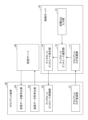
- FIG. 3 is a diagram showing an example of the functional configuration of the client terminal 20 and the control server 10 in the first embodiment.
- the client terminal 20 includes a client log transmitter 21, an upload bit rate controller 22, a transmit data encoder 23, and a receive data decoder 24. Each of these units is realized by one or more programs installed on the client terminal 20 causing the CPU of the client terminal 20 to execute the processing.
- the control server 10 includes a client log collection section 11, a target QoE input section 12, an upload bit rate selection section 13, and an upload bit rate instruction section 14. Each of these units is realized by one or more programs installed in the control server 10 causing the CPU 104 to execute the process.
- the client log transmitting unit 21 of each client terminal 20 periodically (for example, every 1 second) transmits information necessary for quality estimation (information in this cycle) and information necessary for estimating the upload bit rate.
- a log (hereinafter referred to as "client log") including (information in the period) is collected from the client terminal 20 after the start of the web conference, and the collected client log is transmitted to the control server 10.
- the information necessary for quality estimation includes, for example, information regarding the quality of each received video (bit rate, playback stop information (playback stop time, number of times, interval, etc.), frame rate, resolution), information about the client terminal 20 ( Information that can identify the type of terminal being used (own terminal), display size (display area)).
- information regarding the quality of each received video bit rate, playback stop information (playback stop time, number of times, interval, etc.), frame rate, resolution
- For each received video has the same meaning as for each other client terminal 20 (video from).
- each video received by A's client terminal 20 refers to each video of B and C.
- the display size is collected for each received video because it is assumed that the display size (that is, the size on the screen in which other participants are displayed) may differ for each received video.
- the present embodiment allows a situation where the display size of person B and the display size of person C are different on person A's client terminal 20.
- the information necessary for estimating the upload bit rate is, for example, the available upload bandwidth and available download bandwidth of each user (each client terminal 20).
- the client log collection unit 11 of the control server 10 receives the client log transferred from the client log transmission unit 21. Note that if the information included in the client log can be collected on the control server 10 side, the information may be collected on the control server 10 side.
- the control server 10 basically executes the following processing in response to receiving the client log. However, the following process does not have to be executed every time a client log is received.
- the upload bit rate selection unit 13 of the control server 10 selects the bit rate for each source x each destination so as to minimize the amount of transferred data (the sum of bit rates for each source x each destination). Calculate upload bitrate.
- each symbol is as follows.
- U Participating user group BR i,u (t): Bit rate of user i's video received by user u at time t (upload bit rate for i (sender), reception bit rate for u (destination) )
- L Bit rate group with multiple selectable levels
- the upload bit rate for a certain source and destination pair is the bit rate for uploading to the distribution server 30 for the source
- the upload bit rate for the destination is the bit rate (reception bit rate) of the received video distributed from the distribution server 30.
- time t is a preset timing for changing the upload bit rate
- the interval is, for example, the same as the client log collection cycle.
- the upload bit rate selection unit 13 performs the calculation of equation (1) so as to satisfy the following three constraints 1 to 3.
- Constraint 1 is expressed by the following equation (2).
- TargetQoE Target QoE set as a threshold That is, constraint 1 is that each user's estimated QoE needs to be equal to or higher than a target QoE (TargetQoE).
- Constraint 2 is expressed by the following equation (3).
- BR i,u (t) Bit rate of user i's video received by user u at time t
- ULBW i (t) Estimated uploadable bandwidth ⁇ of user i at time t: Safety factor (0- (takes a value of 1) That is, constraint 2 is that the total upload bit rate of each user needs to be less than or equal to the available upload bandwidth. However, there is no need to add up duplicates of the same upload bitrates from the same source (that is, duplicates of the same upload bitrates from the same source are removed and added together).
- Constraint 3 is expressed by the following equation (4).
- BR i,u (t) Bit rate of user i's video received by user u at time t
- Equations (2) to (4) indicate constraint conditions for the optimization problem indicated by Equation (1).
- the upload bit rate selection unit 13 selects the upload bit rate from the bit rate group (L) in multiple stages.
- the bit rate group (L) is given in advance.
- N the number of bit rates (N) that can be selected between the minimum QoE that the service provider should guarantee (hereinafter referred to as "QoE lower ”) and the maximum QoE that the service provider wants to achieve
- QoE upper the number of bit rates (N) that can be selected between the minimum QoE that the service provider should guarantee
- QoE upper the maximum QoE that the service provider wants to achieve
- Equation (5) shows a bit rate calculation formula when QoE is set at regular intervals using the QoE estimation model.
- BR n nth estimated bit rate n: integer between 0-N-1
- N number of selectable bit rates
- QoE upper maximum QoE you want to achieve (e.g., 5)
- QoE lower QoE that should be guaranteed at least (e.g., 3)
- the QoE at fixed intervals is [3, 3.25, 3.5, 3.75, 4, 4.25, 4.5, 4.75 , 5] and BR n is calculated for each of these QoEs.
- QoE u of each user in equation (2) is calculated from the transmitted video of other users. Specifically, QoE u is a QoE value estimated for an interval from T1 seconds before to T2 seconds after the current time using the following equation (6).
- DS i,u (t) Display size of user i displayed on user u's screen at time t BR i,u (t): Bit rate FR i of user i's video received by user u at time t , u (t): Frame rate of user i's video received by user u at time t RES i,u (t): Resolution of user i's video received by user u at time t STOP i,u (t) : Playback stop information of user i's video received by user u at time t
- f QoE is a QoE estimation model for estimating QoE from bit rate, resolution, frame rate, and playback stop information. The one disclosed in Patent Document 3 is used.
- the outermost f() on the right side of equation (6) indicates an equation for estimating long-term QoE.
- the QoE value is calculated every t (for example, every second) within this period, and the QoE value for a certain period is estimated by integrating them.
- the QoE value every t (eg, 1 second) is calculated in f( ) of equation (6).
- the upload bit rate selection unit 13 uses the contents of f() in equation (6) to calculate the QoE value of each u from the client log for each t in the interval from T1 seconds ago to the current time. calculate.
- Step 2 The upload bit rate selection unit 13 uses the contents of f() in equation (6) to calculate the QoE value of each u for every t in the interval T2 seconds after the current time. At this time, the bit rate (BR i,u (t)) is selected from L.
- the value of BR i,u (t) may be selected to decrease from a relatively high bit rate to a low bit rate as t progresses, or from a relatively low bit rate to a high bit rate.
- the value of BR i,u (t) may be selected such that A bit rate may be selected from L based on other rules.
- the latest values of the client log are used for the frame rate, resolution, and display size (FR i,u (t), RES i,u (t), DS i,u (t)), and the playback stop information (STOP i ,u (t)) is , u (t)) may be set to 0.
- the frame rate and resolution may be determined depending on the selected bit rate.
- the resolution and frame rate may be calculated according to the correspondence formula between bit rate, frame rate, and resolution used by the client application.
- the upload bit rate selection unit 13 integrates the QoE value for each t calculated in step 1 and the QoE value for each t calculated in step 2 for each u using f() in equation (6).
- QoE u which is a QoE value for a certain period (T1 to T2), is calculated (estimated) for u .
- the upload bit rate selection unit 13 selects BR i,u (t) from L.
- ULBW i (t) and DLBW u (t) in equations (3) and (4) assume that the upload available bandwidth included in the client log from the client log transmitter 21 continues for T2 seconds. do. That is, the latest client log values may be substituted for ULBW i (t) and DLBW u (t). Note that ULBW i (t) and DLBW u (t) may be estimated using existing band estimation techniques.
- the upload bit rate instruction unit 14 determines the upload bit rate (BR i, u (t)) for each source (i) x destination (u) received from the upload bit rate selector 13 from the client terminal associated with each i. 20 instructs each client terminal 20 to encode at the upload bit rate.
- a certain source terminal i has all (that is, 1 or more) upload bit rate values for the source (i) x destination (u) among the upload bit rates for each source (i) x destination (u). Sent.
- the client upload bit rate control unit 22 of the client terminal 20 sets all upload bit rates received from the upload bit rate instruction unit 14 of the control server 10 to the transmission data encoding unit 23.
- the transmission data encoding unit 23 encodes media data based on the set upload bit rate, and transmits (uploads) the encoded media data to the distribution server 30.
- the distribution server 30 distributes media data uploaded from each client terminal 20 at one or more levels of upload bit rate to client terminals 20 other than the client terminal 20 concerned. At this time, the distribution server 30 does not necessarily need to know the calculation result (selection result) of BR i,u (t) according to equation (1). Basically, in Simulcast, the distribution server 30 determines an appropriate rate according to the download bandwidth of the client terminal 20 and distributes the data, but in this embodiment, information on the download bandwidth is not available at the time of calculating BR i,u (t). This is because it is considered that the bit rate selected by the distribution server 30 will naturally match the calculation result of BR i,u (t) because it is being utilized.
- the calculation result (selection result) of BR i,u (t) may be transmitted from the control server 10 or the client terminal 20 to the distribution server 30.
- the video bit rate for each combination of source and destination is selected so that the amount of data transfer is minimized within the range that achieves the target QoE. Therefore, it is possible to reduce the possibility that an excessive bit rate will be selected when encoding a video. As a result, for example, it is possible to suppress the cost of equipment of the service provider.
- n(BR i (t)) of upload bit rates BR i (t) of each transmission source i in equation (1) is equal to or less than R.
- BR i (t) means the type (list) of upload bit rates from user i as an arbitrary source to all destinations.
- n(X) means the number of X. Due to this constraint, the number of upload bit rates is limited to R for each source i, and each destination user u selects one bit rate from R bit rates for the video from each source i.
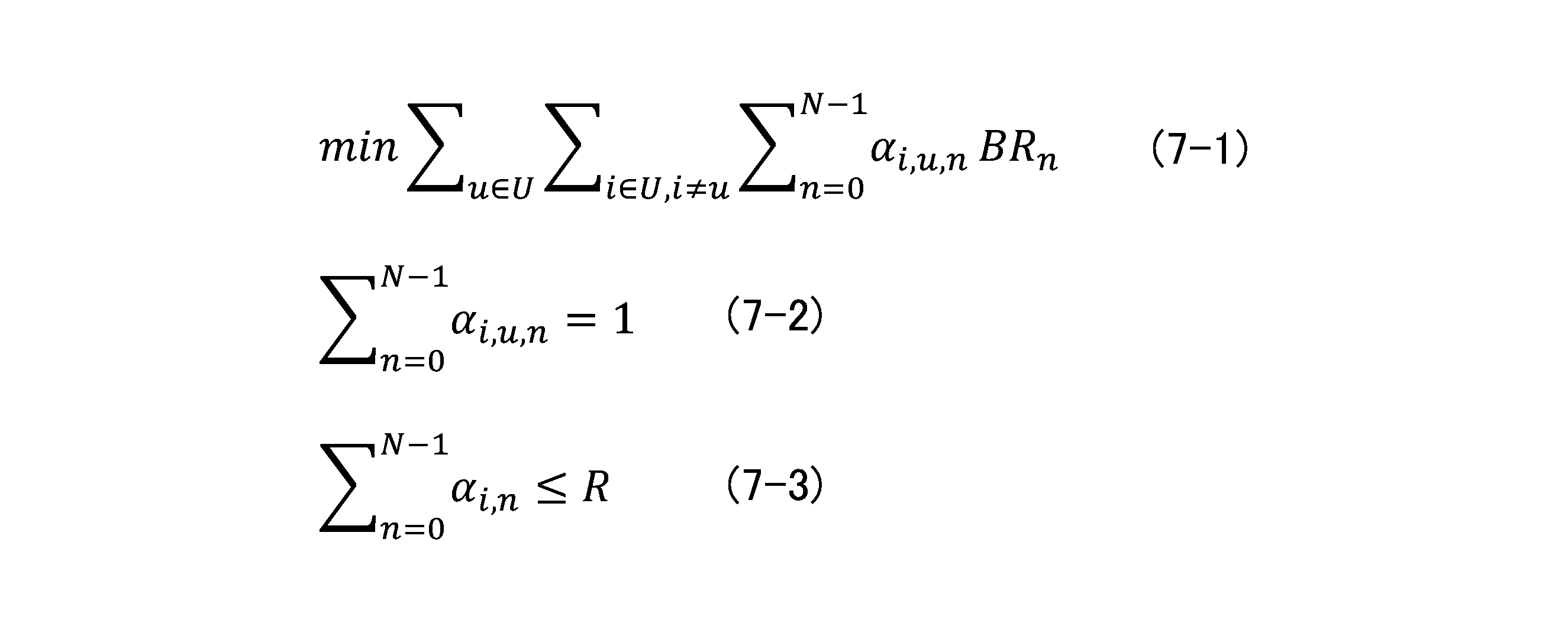
- the upload bit rate selection unit 13 determines the amount of data to be transferred based on the following formula (7-1) instead of formula (1). Calculate the upload bit rate for each source x destination so as to minimize (sum of bit rates for each source x destination). At this time, the constraints of equations (2) to (6) are also valid.
- Equation (7-2) is a constraint that indicates that only one n is adopted for a certain pair of i and u.
- Equation (7-3) indicates a constraint that the number of upload bit rates from any source user i is equal to or less than R. That is, ⁇ i, n is a variable that becomes 1 if ⁇ i, u, n for any u is 1, and becomes 0 if ⁇ i, u, n for all u is 0. .
- control server 10 is an example of a bit rate selection device.
- the client terminal 20 is an example of a first terminal and a second terminal.
- the upload bit rate selection unit 13 is an example of a selection unit.
- the upload bit rate instruction section 14 is an example of an instruction section.
- Distribution server 30 is an example of a distribution device.
- Control server 11 Client log collection unit 12 Target QoE input unit 13 Upload bit rate selection unit 14 Upload bit rate instruction unit 20 Client terminal 21 Client log transmission unit 22 Upload bit rate control unit 23 Transmission data encoding unit 24 Received data decoding Part 30 Distribution server 100 Drive device 101 Recording medium 102 Auxiliary storage device 103 Memory device 104 CPU 105 Interface device B bus
Landscapes
- Engineering & Computer Science (AREA)
- Multimedia (AREA)
- Signal Processing (AREA)
- Computer Networks & Wireless Communication (AREA)
- Two-Way Televisions, Distribution Of Moving Picture Or The Like (AREA)
- Information Transfer Between Computers (AREA)
Abstract
Description

但し、各記号の意味は以下の通りである。
U:参加ユーザ群
BRi,u(t):時刻tにユーザuが受信するユーザiの映像のビットレート(i(送信元)にとってはアップロードビットレート、u(送信先)にとっては受信ビットレート)
L:選択可能な複数段階のビットレート群
なお、送信元×送信先毎のアップロードビットレートとは、例えば、参加者が5人であれば、5×4=20通りのビットレートをいう。なお、送信元×送信先毎のアップロードビットレートのうち、或る送信元及び送信先の組に対するアップロードビットレートは、当該送信元にとっては配信サーバ30へアップロードするビットレートであり、当該送信先にとっては配信サーバ30から配信される受信映像のビットレート(受信ビットレート)である。
制約1は、以下の式(2)で表される。

U:参加ユーザ群
TargetQoE:閾値として設定された目標QoE
すなわち、制約1は、各ユーザの推定されたQoEは目標QoE(TargetQoE)以上である必要があることである。
制約2は、以下の式(3)で表される。

BRi,u(t):時刻tにユーザuが受信するユーザiの映像のビットレート
ULBWi(t)時刻tのユーザiの推定アップロード可能帯域
α:推定誤差を加味した安全係数(0-1の値をとる)
すなわち、制約2は、各ユーザのアップロードビットレートの合計はアップロード可用帯域以下である必要があることである。但し、同一送信元で同一アップロードビットレートは重複して合算する必要はない(すなわち、同一送信元で同一アップロードビットレートの重複は除かれて合算される)。
制約3は、以下の式(4)で表される。

BRi,u(t):時刻tにユーザuが受信するユーザiの映像のビットレート
DLBWu(t):時刻tのユーザuの推定ダウンロード可能帯域
α:推定誤差を加味した安全係数(0-1の値をとる)
すなわち、制約3は、各ユーザのダウンロードビットレート(=受信ビットレート)の合計はダウンロード可用帯域以下の値である必要があることである。

BRn:n番目の推定ビットレート
n:0-N-1の間の整数
N:選択可能ビットレート数
QoEupper:達成したい最大のQoE(e.g.,5)
QoElower:最低でも担保すべきQoE(e.g.,3)
QoElower=3、QoEupper=5、N=9の場合の一定間隔のQoEは、[3、3.25、3.5、3.75、4、4.25、4.5、4.75、5]であり、これらの各QoEに対してBRnが計算される。Nの値を大きくすることで柔軟な制御が可能となるが、アップロードビットレートの種類数が増加する可能性が高まり、クライアント端末20の負荷が増加するリスクがある。

DSi,u(t):時刻tのユーザuの画面に表示されているユーザiの表示サイズ
BRi,u(t):時刻tのユーザuが受信したユーザiの映像のビットレート
FRi,u(t):時刻tのユーザuが受信したユーザiの映像のフレームレート
RESi,u(t):時刻tのユーザuが受信したユーザiの映像の解像度
STOPi,u(t):時刻tのユーザuが受信したユーザiの映像の再生停止情報
また、fQoEは、ビットレート、解像度、フレームレート及び再生停止情報からQoEを推定するためのQoE推定モデルであり、例えば、非特許文献3に開示されたものが利用される。
(step1)アップロードビットレート選択部13は、式(6)のf()の中身を利用して、T1秒前から現在時刻の区間の各tにおけるクライアントログからtごとに各uのQoE値を計算する。
(step2)アップロードビットレート選択部13は、式(6)のf()の中身を利用して、現在時刻からT2秒後の区間のtごとに各uのQoE値を計算する。この際に、ビットレート(BRi,u(t))はLの中から選択される。例えば、tの進行に応じて相対的に高いビットレートから低いビットレートへ下かるようにBRi,u(t)の値が選択されてもよいし、相対的に低いビットレートから高いビットレートへ上があるようにBRi,u(t)の値が選択されるようにしてもよい。その他の規則に基づいてLの中からビットレートが選択されてもよい。また、フレームレート、解像度、表示サイズ(FRi,u(t)、RESi,u(t)、DSi,u(t))はクライアントログの最新値を利用し、再生停止情報(STOPi,u(t))は、0とすることが考えられる。また、クライアントアプリによっては選択ビットレートに応じてフレームレートや解像度を決定する場合がある。そのような場合は、クライアントアプリで利用されているビットレートとフレームレート、解像度の対応式に応じて解像度及びフレームレートを計算してもよい。
(step3)アップロードビットレート選択部13は、step1で計算したtごとのQoE値と、step2で計算したtごとのQoE値とを式(6)のf()でuごとに統合して、各uについて一定期間(T1~T2)のQoE値であるQoEuを計算(推定)する。
11 クライアントログ収集部
12 目標QoE入力部
13 アップロードビットレート選択部
14 アップロードビットレート指示部
20 クライアント端末
21 クライアントログ送信部
22 アップロードビットレート制御部
23 送信データ符号化部
24 受信データ復号化部
30 配信サーバ
100 ドライブ装置
101 記録媒体
102 補助記憶装置
103 メモリ装置
104 CPU
105 インタフェース装置
B バス
Claims (8)
- オンラインリアルタイムコミュニケーションに関して複数の第1の端末のそれぞれから送信される映像を配信装置を介して受信する複数の第2の端末それぞれのユーザの前記映像に関する体感品質が閾値以上であるという制約において、前記複数の第1の端末と前記複数の第2の端末との組み合わせごとの前記映像のビットレートの総和が最小となるように、前記組み合わせごとの前記映像のビットレートを複数段階の値から選択するように構成されている選択部と、
前記第1の端末それぞれに対して、当該第1の端末に係る組み合わせについて前記選択部が選択した1以上のビットレートでの符号化の指示を送信するように構成されている指示部と、
を有することを特徴とするビットレート選択装置。 - 前記選択部は、更に、前記組み合わせごとのビットレートのうち重複を除くビットレートの合計が前記複数の第1の端末から前記配信装置へのアップロードの可用帯域以下であるという制約において、前記組み合わせごとの前記映像のビットレートを選択するように構成されている、
ことを特徴とする請求項1記載のビットレート選択装置。 - 前記選択部は、更に、前記組み合わせごとのビットレートの合計が前記配信装置から前記複数の第2の端末へのダウンロードの可用帯域以下であるという制約において、前記組み合わせごとの前記映像のビットレートを選択するように構成されている、
ことを特徴とする請求項1又は2記載のビットレート選択装置。 - 前記選択部は、更に、前記映像についてそれぞれの前記第1の端末が送信可能なビットレート数が所定数以下であるという制限において、前記組み合わせごとの前記映像のビットレートを選択するように構成されている、
ことを特徴とする請求項1記載のビットレート選択装置。 - オンラインリアルタイムコミュニケーションに関して複数の第1の端末のそれぞれから送信される映像を配信装置を介して受信する複数の第2の端末それぞれのユーザの前記映像に関する体感品質が閾値以上であるという制約において、前記複数の第1の端末と前記複数の第2の端末との組み合わせごとの前記映像のビットレートの総和が最小となるように、前記組み合わせごとの前記映像のビットレートを複数段階の値から選択する選択手順と、
前記第1の端末それぞれに対して、当該第1の端末に係る組み合わせについて前記選択手順が選択した1以上のビットレートでの符号化の指示を送信する指示手順と、
をコンピュータが実行することを特徴とするビットレート選択方法。 - 前記選択手順は、更に、前記組み合わせごとのビットレートのうち重複を除くビットレートの合計が前記複数の第1の端末から前記配信装置へのアップロードの可用帯域以下であるという制約において、前記組み合わせごとの前記映像のビットレートを選択する、
ことを特徴とする請求項5記載のビットレート選択方法。 - 前記選択手順は、更に、前記組み合わせごとのビットレートの合計が前記配信装置から前記複数の第2の端末へのダウンロードの可用帯域以下であるという制約において、前記組み合わせごとの前記映像のビットレートを選択する、
ことを特徴とする請求項5又は6記載のビットレート選択方法。 - オンラインリアルタイムコミュニケーションに関して複数の第1の端末のそれぞれから送信される映像を配信装置を介して受信する複数の第2の端末それぞれのユーザの前記映像に関する体感品質が閾値以上であるという制約において、前記複数の第1の端末と前記複数の第2の端末との組み合わせごとの前記映像のビットレートの総和が最小となるように、前記組み合わせごとの前記映像のビットレートを複数段階の値から選択する選択手順と、
前記第1の端末それぞれに対して、当該第1の端末に係る組み合わせについて前記選択手順が選択した1以上のビットレートでの符号化の指示を送信する指示手順と、
をコンピュータに実行させることを特徴とするプログラム。
Priority Applications (2)
| Application Number | Priority Date | Filing Date | Title |
|---|---|---|---|
| US18/860,843 US20250301033A1 (en) | 2022-05-11 | 2023-05-02 | Bit-rate selection apparatus, bit-rate selection method and program |
| JP2024520432A JP7720009B2 (ja) | 2022-05-11 | 2023-05-02 | ビットレート選択装置、ビットレート選択方法及びプログラム |
Applications Claiming Priority (2)
| Application Number | Priority Date | Filing Date | Title |
|---|---|---|---|
| JPPCT/JP2022/019985 | 2022-05-11 | ||
| PCT/JP2022/019985 WO2023218572A1 (ja) | 2022-05-11 | 2022-05-11 | ビットレート選択装置、ビットレート選択方法及びプログラム |
Publications (1)
| Publication Number | Publication Date |
|---|---|
| WO2023219043A1 true WO2023219043A1 (ja) | 2023-11-16 |
Family
ID=88730062
Family Applications (2)
| Application Number | Title | Priority Date | Filing Date |
|---|---|---|---|
| PCT/JP2022/019985 Ceased WO2023218572A1 (ja) | 2022-05-11 | 2022-05-11 | ビットレート選択装置、ビットレート選択方法及びプログラム |
| PCT/JP2023/017171 Ceased WO2023219043A1 (ja) | 2022-05-11 | 2023-05-02 | ビットレート選択装置、ビットレート選択方法及びプログラム |
Family Applications Before (1)
| Application Number | Title | Priority Date | Filing Date |
|---|---|---|---|
| PCT/JP2022/019985 Ceased WO2023218572A1 (ja) | 2022-05-11 | 2022-05-11 | ビットレート選択装置、ビットレート選択方法及びプログラム |
Country Status (3)
| Country | Link |
|---|---|
| US (1) | US20250301033A1 (ja) |
| JP (1) | JP7720009B2 (ja) |
| WO (2) | WO2023218572A1 (ja) |
Citations (2)
| Publication number | Priority date | Publication date | Assignee | Title |
|---|---|---|---|---|
| US20080101410A1 (en) * | 2006-10-25 | 2008-05-01 | Microsoft Corporation | Techniques for managing output bandwidth for a conferencing server |
| US20210258364A1 (en) * | 2020-01-06 | 2021-08-19 | Dialogic Corporation | Dynamically Changing Characteristics of Simulcast Video Streams in Selective Forwarding |
-
2022
- 2022-05-11 WO PCT/JP2022/019985 patent/WO2023218572A1/ja not_active Ceased
-
2023
- 2023-05-02 JP JP2024520432A patent/JP7720009B2/ja active Active
- 2023-05-02 WO PCT/JP2023/017171 patent/WO2023219043A1/ja not_active Ceased
- 2023-05-02 US US18/860,843 patent/US20250301033A1/en active Pending
Patent Citations (2)
| Publication number | Priority date | Publication date | Assignee | Title |
|---|---|---|---|---|
| US20080101410A1 (en) * | 2006-10-25 | 2008-05-01 | Microsoft Corporation | Techniques for managing output bandwidth for a conferencing server |
| US20210258364A1 (en) * | 2020-01-06 | 2021-08-19 | Dialogic Corporation | Dynamically Changing Characteristics of Simulcast Video Streams in Selective Forwarding |
Also Published As
| Publication number | Publication date |
|---|---|
| JPWO2023219043A1 (ja) | 2023-11-16 |
| JP7720009B2 (ja) | 2025-08-07 |
| WO2023218572A1 (ja) | 2023-11-16 |
| US20250301033A1 (en) | 2025-09-25 |
Similar Documents
| Publication | Publication Date | Title |
|---|---|---|
| US11190570B2 (en) | Video encoding using starve mode | |
| CN104247368B (zh) | 用于提供多个经译码的内容流的方法和设备 | |
| EP1622385B1 (en) | Media transrating over a bandwidth-limited network | |
| US6453336B1 (en) | Video conferencing with adaptive client-controlled resource utilization | |
| JP6308718B2 (ja) | マルチパス環境におけるアダプティブストリーミングのためのシステムと方法 | |
| JP5069240B2 (ja) | 複数のデータチャネル転送システム及び方法 | |
| US20210127154A1 (en) | Edge optimized transrating system | |
| EP3127285B1 (en) | Method and systems for optimizing bandwidth utilization in a multi-participant full mesh peer-to-peer video session | |
| JP5147950B2 (ja) | 可変帯域幅のチャンネルを介してサイマル放送を行う装置および方法 | |
| US12574581B2 (en) | Video stream bitrate adjustment method and apparatus, computer device, and storage medium | |
| US11290680B1 (en) | High-fidelity freeze-frame for precision video communication applications | |
| TW202143740A (zh) | 可調適視訊串流系統與方法 | |
| JP2020507235A (ja) | データバッファリング方法、ネットワーク機器、及び記憶媒体 | |
| US10218757B2 (en) | System and methods for dynamic transcoder rate adaption for adaptive bit rate streaming | |
| CN110956683A (zh) | 信息处理系统、终端装置及计算机可读介质 | |
| JP6793526B2 (ja) | 動画配信システム、配信サーバ、及びプログラム | |
| JP7720009B2 (ja) | ビットレート選択装置、ビットレート選択方法及びプログラム | |
| JP7448091B2 (ja) | 制御装置、制御方法及びプログラム | |
| Yokota et al. | Quality-based video bitrate control for WebRTC-based teleconference services | |
| WO2024214216A1 (ja) | 通信システム、ビットレート選択装置、ビットレート選択方法及びプログラム | |
| Mvumbi et al. | An online meeting tool for low bandwidth environments | |
| Chakareski et al. | Delay-based overlay construction in P2P video broadcast | |
| Chakareski et al. | Distributed sender-driven video streaming | |
| HK40097736A (zh) | 视频流码率调整方法、装置、计算机设备和存储介质 | |
| JP2012004970A (ja) | コンテンツ配信装置、配信サーバー装置及びプログラム |
Legal Events
| Date | Code | Title | Description |
|---|---|---|---|
| 121 | Ep: the epo has been informed by wipo that ep was designated in this application |
Ref document number: 23803520 Country of ref document: EP Kind code of ref document: A1 |
|
| ENP | Entry into the national phase |
Ref document number: 2024520432 Country of ref document: JP Kind code of ref document: A |
|
| WWE | Wipo information: entry into national phase |
Ref document number: 18860843 Country of ref document: US |
|
| NENP | Non-entry into the national phase |
Ref country code: DE |
|
| 122 | Ep: pct application non-entry in european phase |
Ref document number: 23803520 Country of ref document: EP Kind code of ref document: A1 |
|
| WWP | Wipo information: published in national office |
Ref document number: 18860843 Country of ref document: US |