WO2023218731A1 - Steel sheet, member, and method for producing same - Google Patents
Steel sheet, member, and method for producing same Download PDFInfo
- Publication number
- WO2023218731A1 WO2023218731A1 PCT/JP2023/006925 JP2023006925W WO2023218731A1 WO 2023218731 A1 WO2023218731 A1 WO 2023218731A1 JP 2023006925 W JP2023006925 W JP 2023006925W WO 2023218731 A1 WO2023218731 A1 WO 2023218731A1
- Authority
- WO
- WIPO (PCT)
- Prior art keywords
- less
- steel plate
- bending
- layer
- content
- Prior art date
Links
- 229910000831 Steel Inorganic materials 0.000 title claims abstract description 319
- 239000010959 steel Substances 0.000 title claims abstract description 319
- 238000004519 manufacturing process Methods 0.000 title claims description 37
- 229910001563 bainite Inorganic materials 0.000 claims abstract description 168
- 229910000734 martensite Inorganic materials 0.000 claims abstract description 136
- 229910001566 austenite Inorganic materials 0.000 claims abstract description 89
- 230000000717 retained effect Effects 0.000 claims abstract description 67
- 229910000859 α-Fe Inorganic materials 0.000 claims abstract description 42
- 150000001247 metal acetylides Chemical class 0.000 claims abstract description 39
- 239000000203 mixture Substances 0.000 claims abstract description 20
- UFHFLCQGNIYNRP-UHFFFAOYSA-N Hydrogen Chemical compound [H][H] UFHFLCQGNIYNRP-UHFFFAOYSA-N 0.000 claims abstract description 19
- 229910052739 hydrogen Inorganic materials 0.000 claims abstract description 19
- 239000001257 hydrogen Substances 0.000 claims abstract description 19
- 239000010410 layer Substances 0.000 claims description 167
- 238000000034 method Methods 0.000 claims description 116
- 238000000137 annealing Methods 0.000 claims description 87
- 238000001816 cooling Methods 0.000 claims description 86
- 238000007747 plating Methods 0.000 claims description 85
- 238000005096 rolling process Methods 0.000 claims description 61
- 229910052751 metal Inorganic materials 0.000 claims description 52
- 239000002184 metal Substances 0.000 claims description 52
- 238000005098 hot rolling Methods 0.000 claims description 29
- 238000005246 galvanizing Methods 0.000 claims description 27
- 238000005097 cold rolling Methods 0.000 claims description 24
- 239000013078 crystal Substances 0.000 claims description 21
- 239000002344 surface layer Substances 0.000 claims description 21
- 239000012535 impurity Substances 0.000 claims description 19
- 238000005259 measurement Methods 0.000 claims description 19
- 229910052742 iron Inorganic materials 0.000 claims description 15
- 239000010960 cold rolled steel Substances 0.000 claims description 10
- 238000005304 joining Methods 0.000 claims description 7
- 239000000126 substance Substances 0.000 abstract description 3
- 238000005452 bending Methods 0.000 description 257
- 238000012360 testing method Methods 0.000 description 210
- XEEYBQQBJWHFJM-UHFFFAOYSA-N iron Substances [Fe] XEEYBQQBJWHFJM-UHFFFAOYSA-N 0.000 description 71
- 239000002585 base Substances 0.000 description 54
- 238000009713 electroplating Methods 0.000 description 31
- 239000011701 zinc Substances 0.000 description 31
- 229910001335 Galvanized steel Inorganic materials 0.000 description 25
- 239000008397 galvanized steel Substances 0.000 description 25
- 238000011282 treatment Methods 0.000 description 25
- 238000003303 reheating Methods 0.000 description 24
- 230000007423 decrease Effects 0.000 description 23
- 239000002244 precipitate Substances 0.000 description 22
- 230000000694 effects Effects 0.000 description 19
- 229910052748 manganese Inorganic materials 0.000 description 16
- 238000005336 cracking Methods 0.000 description 15
- 229910052761 rare earth metal Inorganic materials 0.000 description 15
- 229910052799 carbon Inorganic materials 0.000 description 14
- 238000010438 heat treatment Methods 0.000 description 14
- 125000006850 spacer group Chemical group 0.000 description 14
- 229910052725 zinc Inorganic materials 0.000 description 14
- 238000005275 alloying Methods 0.000 description 12
- 238000005498 polishing Methods 0.000 description 12
- 229910052710 silicon Inorganic materials 0.000 description 12
- 230000009466 transformation Effects 0.000 description 12
- 229910052745 lead Inorganic materials 0.000 description 11
- 239000000463 material Substances 0.000 description 11
- 229910052797 bismuth Inorganic materials 0.000 description 10
- 230000001276 controlling effect Effects 0.000 description 10
- HCHKCACWOHOZIP-UHFFFAOYSA-N Zinc Chemical group [Zn] HCHKCACWOHOZIP-UHFFFAOYSA-N 0.000 description 9
- 229910052782 aluminium Inorganic materials 0.000 description 9
- 229910003460 diamond Inorganic materials 0.000 description 9
- 239000010432 diamond Substances 0.000 description 9
- 238000000465 moulding Methods 0.000 description 9
- 238000009864 tensile test Methods 0.000 description 9
- VEXZGXHMUGYJMC-UHFFFAOYSA-N Hydrochloric acid Chemical compound Cl VEXZGXHMUGYJMC-UHFFFAOYSA-N 0.000 description 8
- 229910052785 arsenic Inorganic materials 0.000 description 8
- 238000005554 pickling Methods 0.000 description 8
- 229910052718 tin Inorganic materials 0.000 description 8
- 238000003466 welding Methods 0.000 description 8
- 229910052792 caesium Inorganic materials 0.000 description 7
- 229910052804 chromium Inorganic materials 0.000 description 7
- 229910052732 germanium Inorganic materials 0.000 description 7
- 229910052735 hafnium Inorganic materials 0.000 description 7
- 229910052759 nickel Inorganic materials 0.000 description 7
- 150000004767 nitrides Chemical class 0.000 description 7
- 229910052757 nitrogen Inorganic materials 0.000 description 7
- 229910052698 phosphorus Inorganic materials 0.000 description 7
- 229910052714 tellurium Inorganic materials 0.000 description 7
- QAOWNCQODCNURD-UHFFFAOYSA-N Sulfuric acid Chemical compound OS(O)(=O)=O QAOWNCQODCNURD-UHFFFAOYSA-N 0.000 description 6
- 229910052787 antimony Inorganic materials 0.000 description 6
- 229910052711 selenium Inorganic materials 0.000 description 6
- 229910052712 strontium Inorganic materials 0.000 description 6
- 229910052719 titanium Inorganic materials 0.000 description 6
- 229910045601 alloy Inorganic materials 0.000 description 5
- 239000000956 alloy Substances 0.000 description 5
- PNEYBMLMFCGWSK-UHFFFAOYSA-N aluminium oxide Inorganic materials [O-2].[O-2].[O-2].[Al+3].[Al+3] PNEYBMLMFCGWSK-UHFFFAOYSA-N 0.000 description 5
- 230000015572 biosynthetic process Effects 0.000 description 5
- 229910052802 copper Inorganic materials 0.000 description 5
- 238000010586 diagram Methods 0.000 description 5
- 238000000227 grinding Methods 0.000 description 5
- 229910001562 pearlite Inorganic materials 0.000 description 5
- 238000012545 processing Methods 0.000 description 5
- 238000001878 scanning electron micrograph Methods 0.000 description 5
- 238000010008 shearing Methods 0.000 description 5
- 229910052717 sulfur Inorganic materials 0.000 description 5
- 238000010998 test method Methods 0.000 description 5
- 229910052720 vanadium Inorganic materials 0.000 description 5
- VYPSYNLAJGMNEJ-UHFFFAOYSA-N Silicium dioxide Chemical compound O=[Si]=O VYPSYNLAJGMNEJ-UHFFFAOYSA-N 0.000 description 4
- 238000010521 absorption reaction Methods 0.000 description 4
- 239000011248 coating agent Substances 0.000 description 4
- 238000000576 coating method Methods 0.000 description 4
- 239000008119 colloidal silica Substances 0.000 description 4
- 238000007796 conventional method Methods 0.000 description 4
- 238000005516 engineering process Methods 0.000 description 4
- 150000002500 ions Chemical class 0.000 description 4
- 229910052758 niobium Inorganic materials 0.000 description 4
- 238000004080 punching Methods 0.000 description 4
- 239000011800 void material Substances 0.000 description 4
- 238000005406 washing Methods 0.000 description 4
- XLYOFNOQVPJJNP-UHFFFAOYSA-N water Substances O XLYOFNOQVPJJNP-UHFFFAOYSA-N 0.000 description 4
- MUBZPKHOEPUJKR-UHFFFAOYSA-N Oxalic acid Chemical compound OC(=O)C(O)=O MUBZPKHOEPUJKR-UHFFFAOYSA-N 0.000 description 3
- 229910052796 boron Inorganic materials 0.000 description 3
- 229910052791 calcium Inorganic materials 0.000 description 3
- 239000007789 gas Substances 0.000 description 3
- 229910052749 magnesium Inorganic materials 0.000 description 3
- 238000002844 melting Methods 0.000 description 3
- 230000008018 melting Effects 0.000 description 3
- 229910052750 molybdenum Inorganic materials 0.000 description 3
- 239000000243 solution Substances 0.000 description 3
- 229910052715 tantalum Inorganic materials 0.000 description 3
- 150000003568 thioethers Chemical class 0.000 description 3
- 229910052721 tungsten Inorganic materials 0.000 description 3
- GRYLNZFGIOXLOG-UHFFFAOYSA-N Nitric acid Chemical compound O[N+]([O-])=O GRYLNZFGIOXLOG-UHFFFAOYSA-N 0.000 description 2
- NBIIXXVUZAFLBC-UHFFFAOYSA-N Phosphoric acid Chemical compound OP(O)(O)=O NBIIXXVUZAFLBC-UHFFFAOYSA-N 0.000 description 2
- 239000002253 acid Substances 0.000 description 2
- XAGFODPZIPBFFR-UHFFFAOYSA-N aluminium Chemical compound [Al] XAGFODPZIPBFFR-UHFFFAOYSA-N 0.000 description 2
- 229910052790 beryllium Inorganic materials 0.000 description 2
- 229910052793 cadmium Inorganic materials 0.000 description 2
- 238000006243 chemical reaction Methods 0.000 description 2
- 238000009749 continuous casting Methods 0.000 description 2
- 230000002596 correlated effect Effects 0.000 description 2
- 230000001186 cumulative effect Effects 0.000 description 2
- 238000005238 degreasing Methods 0.000 description 2
- 238000009792 diffusion process Methods 0.000 description 2
- 239000000446 fuel Substances 0.000 description 2
- 229910052733 gallium Inorganic materials 0.000 description 2
- 229910052737 gold Inorganic materials 0.000 description 2
- 229910052738 indium Inorganic materials 0.000 description 2
- 239000003112 inhibitor Substances 0.000 description 2
- 229910052741 iridium Inorganic materials 0.000 description 2
- 239000007788 liquid Substances 0.000 description 2
- 229910052744 lithium Inorganic materials 0.000 description 2
- 230000014759 maintenance of location Effects 0.000 description 2
- 229910052753 mercury Inorganic materials 0.000 description 2
- 229910017604 nitric acid Inorganic materials 0.000 description 2
- 229910052762 osmium Inorganic materials 0.000 description 2
- 229910052760 oxygen Inorganic materials 0.000 description 2
- 229910052763 palladium Inorganic materials 0.000 description 2
- 239000002994 raw material Substances 0.000 description 2
- 229910052703 rhodium Inorganic materials 0.000 description 2
- 229910052707 ruthenium Inorganic materials 0.000 description 2
- 229910052706 scandium Inorganic materials 0.000 description 2
- 229910052709 silver Inorganic materials 0.000 description 2
- 238000005728 strengthening Methods 0.000 description 2
- 238000005496 tempering Methods 0.000 description 2
- 229910052727 yttrium Inorganic materials 0.000 description 2
- YKCSYIYQRSVLAK-UHFFFAOYSA-N 3,5-dimethyl-2-phenylmorpholine Chemical compound CC1NC(C)COC1C1=CC=CC=C1 YKCSYIYQRSVLAK-UHFFFAOYSA-N 0.000 description 1
- 229910000521 B alloy Inorganic materials 0.000 description 1
- 229910001339 C alloy Inorganic materials 0.000 description 1
- OKTJSMMVPCPJKN-UHFFFAOYSA-N Carbon Chemical compound [C] OKTJSMMVPCPJKN-UHFFFAOYSA-N 0.000 description 1
- 229910052684 Cerium Inorganic materials 0.000 description 1
- 229910002551 Fe-Mn Inorganic materials 0.000 description 1
- 229910017112 Fe—C Inorganic materials 0.000 description 1
- 229910017135 Fe—O Inorganic materials 0.000 description 1
- 229910001030 Iron–nickel alloy Inorganic materials 0.000 description 1
- 229910052765 Lutetium Inorganic materials 0.000 description 1
- 229910001182 Mo alloy Inorganic materials 0.000 description 1
- 229910001199 N alloy Inorganic materials 0.000 description 1
- 229910001096 P alloy Inorganic materials 0.000 description 1
- PMZURENOXWZQFD-UHFFFAOYSA-L Sodium Sulfate Chemical compound [Na+].[Na+].[O-]S([O-])(=O)=O PMZURENOXWZQFD-UHFFFAOYSA-L 0.000 description 1
- UCKMPCXJQFINFW-UHFFFAOYSA-N Sulphide Chemical compound [S-2] UCKMPCXJQFINFW-UHFFFAOYSA-N 0.000 description 1
- 229910001080 W alloy Inorganic materials 0.000 description 1
- 238000002441 X-ray diffraction Methods 0.000 description 1
- 230000002159 abnormal effect Effects 0.000 description 1
- 239000002250 absorbent Substances 0.000 description 1
- 230000002745 absorbent Effects 0.000 description 1
- 150000007513 acids Chemical class 0.000 description 1
- 239000003513 alkali Substances 0.000 description 1
- 229910000147 aluminium phosphate Inorganic materials 0.000 description 1
- 238000004458 analytical method Methods 0.000 description 1
- 239000002518 antifoaming agent Substances 0.000 description 1
- 239000007864 aqueous solution Substances 0.000 description 1
- 230000033228 biological regulation Effects 0.000 description 1
- KGBXLFKZBHKPEV-UHFFFAOYSA-N boric acid Chemical compound OB(O)O KGBXLFKZBHKPEV-UHFFFAOYSA-N 0.000 description 1
- 239000004327 boric acid Substances 0.000 description 1
- 238000005266 casting Methods 0.000 description 1
- 239000002738 chelating agent Substances 0.000 description 1
- 230000000052 comparative effect Effects 0.000 description 1
- 239000002131 composite material Substances 0.000 description 1
- 239000000470 constituent Substances 0.000 description 1
- 230000007797 corrosion Effects 0.000 description 1
- 238000005260 corrosion Methods 0.000 description 1
- 238000005261 decarburization Methods 0.000 description 1
- 230000003247 decreasing effect Effects 0.000 description 1
- 230000007547 defect Effects 0.000 description 1
- 230000002950 deficient Effects 0.000 description 1
- 230000008021 deposition Effects 0.000 description 1
- 238000003795 desorption Methods 0.000 description 1
- 238000011156 evaluation Methods 0.000 description 1
- 239000012467 final product Substances 0.000 description 1
- 230000005484 gravity Effects 0.000 description 1
- 238000009499 grossing Methods 0.000 description 1
- 238000007542 hardness measurement Methods 0.000 description 1
- 230000006698 induction Effects 0.000 description 1
- 238000013101 initial test Methods 0.000 description 1
- 229910000358 iron sulfate Inorganic materials 0.000 description 1
- BAUYGSIQEAFULO-UHFFFAOYSA-L iron(2+) sulfate (anhydrous) Chemical compound [Fe+2].[O-]S([O-])(=O)=O BAUYGSIQEAFULO-UHFFFAOYSA-L 0.000 description 1
- 230000001788 irregular Effects 0.000 description 1
- 229910052747 lanthanoid Inorganic materials 0.000 description 1
- 150000002602 lanthanoids Chemical class 0.000 description 1
- 229910052746 lanthanum Inorganic materials 0.000 description 1
- FZLIPJUXYLNCLC-UHFFFAOYSA-N lanthanum atom Chemical compound [La] FZLIPJUXYLNCLC-UHFFFAOYSA-N 0.000 description 1
- OHSVLFRHMCKCQY-UHFFFAOYSA-N lutetium atom Chemical compound [Lu] OHSVLFRHMCKCQY-UHFFFAOYSA-N 0.000 description 1
- 239000000155 melt Substances 0.000 description 1
- 229910021645 metal ion Inorganic materials 0.000 description 1
- 239000003595 mist Substances 0.000 description 1
- 229910052755 nonmetal Inorganic materials 0.000 description 1
- 150000007524 organic acids Chemical class 0.000 description 1
- 235000006408 oxalic acid Nutrition 0.000 description 1
- 230000003647 oxidation Effects 0.000 description 1
- 238000007254 oxidation reaction Methods 0.000 description 1
- 239000006174 pH buffer Substances 0.000 description 1
- OTYBMLCTZGSZBG-UHFFFAOYSA-L potassium sulfate Chemical compound [K+].[K+].[O-]S([O-])(=O)=O OTYBMLCTZGSZBG-UHFFFAOYSA-L 0.000 description 1
- 229910052939 potassium sulfate Inorganic materials 0.000 description 1
- 235000011151 potassium sulphates Nutrition 0.000 description 1
- 238000001556 precipitation Methods 0.000 description 1
- 238000003825 pressing Methods 0.000 description 1
- 238000002203 pretreatment Methods 0.000 description 1
- 230000002265 prevention Effects 0.000 description 1
- 238000003672 processing method Methods 0.000 description 1
- 239000000047 product Substances 0.000 description 1
- 238000000988 reflection electron microscopy Methods 0.000 description 1
- 230000003014 reinforcing effect Effects 0.000 description 1
- 239000011347 resin Substances 0.000 description 1
- 229920005989 resin Polymers 0.000 description 1
- SIXSYDAISGFNSX-UHFFFAOYSA-N scandium atom Chemical compound [Sc] SIXSYDAISGFNSX-UHFFFAOYSA-N 0.000 description 1
- 238000005204 segregation Methods 0.000 description 1
- 230000035939 shock Effects 0.000 description 1
- 229910052938 sodium sulfate Inorganic materials 0.000 description 1
- 235000011152 sodium sulphate Nutrition 0.000 description 1
- 239000006104 solid solution Substances 0.000 description 1
- 238000010301 surface-oxidation reaction Methods 0.000 description 1
- 230000037303 wrinkles Effects 0.000 description 1
- VWQVUPCCIRVNHF-UHFFFAOYSA-N yttrium atom Chemical compound [Y] VWQVUPCCIRVNHF-UHFFFAOYSA-N 0.000 description 1
- 229910052726 zirconium Inorganic materials 0.000 description 1
Images


Classifications
-
- C—CHEMISTRY; METALLURGY
- C21—METALLURGY OF IRON
- C21D—MODIFYING THE PHYSICAL STRUCTURE OF FERROUS METALS; GENERAL DEVICES FOR HEAT TREATMENT OF FERROUS OR NON-FERROUS METALS OR ALLOYS; MAKING METAL MALLEABLE, e.g. BY DECARBURISATION OR TEMPERING
- C21D9/00—Heat treatment, e.g. annealing, hardening, quenching or tempering, adapted for particular articles; Furnaces therefor
- C21D9/46—Heat treatment, e.g. annealing, hardening, quenching or tempering, adapted for particular articles; Furnaces therefor for sheet metals
-
- C—CHEMISTRY; METALLURGY
- C22—METALLURGY; FERROUS OR NON-FERROUS ALLOYS; TREATMENT OF ALLOYS OR NON-FERROUS METALS
- C22C—ALLOYS
- C22C38/00—Ferrous alloys, e.g. steel alloys
-
- C—CHEMISTRY; METALLURGY
- C22—METALLURGY; FERROUS OR NON-FERROUS ALLOYS; TREATMENT OF ALLOYS OR NON-FERROUS METALS
- C22C—ALLOYS
- C22C38/00—Ferrous alloys, e.g. steel alloys
- C22C38/06—Ferrous alloys, e.g. steel alloys containing aluminium
-
- C—CHEMISTRY; METALLURGY
- C22—METALLURGY; FERROUS OR NON-FERROUS ALLOYS; TREATMENT OF ALLOYS OR NON-FERROUS METALS
- C22C—ALLOYS
- C22C38/00—Ferrous alloys, e.g. steel alloys
- C22C38/60—Ferrous alloys, e.g. steel alloys containing lead, selenium, tellurium, or antimony, or more than 0.04% by weight of sulfur
-
- C—CHEMISTRY; METALLURGY
- C22—METALLURGY; FERROUS OR NON-FERROUS ALLOYS; TREATMENT OF ALLOYS OR NON-FERROUS METALS
- C22C—ALLOYS
- C22C18/00—Alloys based on zinc
Definitions
- the present invention relates to steel plates, members made from the steel plates, and methods of manufacturing them.
- high-strength steel plates are used for the main structural members and reinforcing members (hereinafter also referred to as automobile frame structural members) that are assembled into the frame of the car cabin.
- the number of applications of high-strength steel plates of 780 MPa or higher is increasing.
- high-strength steel plates used for automobile frame structural members and the like are required to have high member strength when press-formed.
- YR yield ratio
- YS yield stress
- TS yield stress
- impact absorption energy the impact absorption energy at the time of a car collision increases.
- a crash box has a bent portion. Therefore, from the viewpoint of press formability, it is preferable to use a steel plate having high bendability for such parts.
- steel plates that are used as raw materials for automobile parts are often galvanized. Therefore, it is desired to develop a hot-dip galvanized steel sheet that not only has high strength but also has excellent press formability and impact resistance.
- Patent Document 1 as a steel plate that is a material for such automobile parts, C is 0.04 to 0.22%, Si is 1.0% or less, and Mn is 3.0%. % or less, P is 0.05% or less, S is 0.01% or less, Al is 0.01-0.1%, and N is 0.001-0.005%, with the balance being Fe and unavoidable impurities. It is composed of a ferrite phase as a main phase and a martensite phase as a second phase, and the maximum grain size of the martensite phase is 2 ⁇ m or less and its area ratio is 5% or more.
- a high-strength steel plate with excellent stretch flangeability and collision resistance characteristics is disclosed.
- Patent Document 2 describes a cold-rolled steel sheet whose surface layer has been polished to a thickness of 0.1 ⁇ m or more and which is pre-plated with Ni at 0.2 g/m2 or more and 2.0 g/m2 or less .
- Containing two or more types of martensite [3] of three types of martensite [1], [2], and [3], 1% or more of bainite, and 0 to 10% of pearlite, and containing the three types of martensite [1], [2], and [3] are volume fractions, respectively: martensite [1]: 0% or more, 50% or less, martensite [2]: 0% or more, less than 20%, martensite [3] : 1% or more and 30% or less, and has a hot-dip galvanized layer containing less than 7% Fe, with the remainder consisting of Zn, Al and inevitable impurities, and has a tensile strength TS (MPa), Plating adhesion characterized by having a total elongation rate EL (%) and a hole expansion rate ⁇ (%) of TS x EL of 18000 MPa % or more, TS x ⁇ of 35000 MPa % or more, and a tensile strength of 980 MP
- High-strength hot-dip galvanized steel sheet with excellent formability (martensite [1]: C concentration (CM1) is less than 0.8%, hardness Hv1 is Hv1/(-982.1 ⁇ CM1 2 +1676 ⁇ CM1+189) ⁇ 0.60, martensite [2]: C concentration (CM2) is 0.8% or more, hardness Hv2 is Hv2/(-982.1 ⁇ CM2 2 +1676 ⁇ CM2+189) ⁇ 0.60, martensite [3]: It is disclosed that the C concentration (CM3) is 0.8% or more and the hardness Hv3 is Hv3/(-982.1 ⁇ CM3 2 +1676 ⁇ CM3+189) ⁇ 0.80.
- Patent Document 3 in mass %, C: 0.15% or more and 0.25% or less, Si: 0.50% or more and 2.5% or less, Mn: 2.3% or more and 4.0% or less. , P: 0.100% or less, S: 0.02% or less, Al: 0.01% or more and 2.5% or less, with the balance consisting of Fe and unavoidable impurities.
- Martensite phase 30% or more and 73% or less, ferrite phase: 25% or more and 68% or less, retained austenite phase: 2% or more and 20% or less, other phases: 10% or less (including 0%), and The other phases include martensitic phase: 3% or less (including 0%), bainitic ferrite phase: less than 5% (including 0%), and the average grain size of the tempered martensitic phase is 8 ⁇ m.
- Patent Document 4 discloses an alloyed hot-dip galvanized steel sheet having an alloyed hot-dip galvanized layer on the surface of the steel sheet, in which the steel sheet has a carbon content of 0.03% or more and 0.35% or less in mass %. , Si: 0.005% or more and 2.0% or less, Mn: 1.0% or more and 4.0% or less, P: 0.0004% or more and 0.1% or less, S: 0.02% or less, sol. It has a chemical composition consisting of Al: 0.0002% or more and 2.0% or less, N: 0.01% or less, and the balance is Fe and impurities, and is stretched in the rolling direction at a depth of 50 ⁇ m from the surface of the steel plate.
- the average spacing in the direction perpendicular to the rolling direction of the enriched regions where Mn and/or Si are concentrated is 1000 ⁇ m or less, and the number density of cracks with a depth of 3 ⁇ m or more and 10 ⁇ m or less on the surface of the steel sheet is 3 pieces/mm or more and 1000 pieces/mm or less, and contains bainite: 60% or more, retained austenite: 1% or more, martensite: 1% or more, and ferrite: 2% or more and less than 20%, and
- the alloyed hot-dip galvanized steel sheet has a steel structure in which the average distance between the ultrahard phases, which is the average value of the closest distance between martensite and retained austenite, is 20 ⁇ m or less, and the alloyed hot-dip galvanized steel sheet has a tensile strength (TS) of 780 MPa or more.
- TS tensile strength
- steel plates with a tensile strength TS (hereinafter sometimes simply referred to as TS) exceeding 590 MPa are increasingly being used in automobile frame members such as center pillars, but they are not suitable for front side members and rear side members.
- TS tensile strength
- the impact energy absorbing members of typical automobiles are limited to steel plates with a TS of 590 MPa.
- the yield stress YS (hereinafter sometimes simply referred to as YS) and the yield ratio YR (hereinafter simply referred to as YR) are ) is effective.
- YS and YR of a steel sheet are increased, press formability, particularly properties such as ductility, hole expandability, and bendability are generally reduced.
- the steel sheets disclosed in Patent Documents 1 to 4 also have a TS of 1180 MPa or more, high YS and YR, excellent press formability (ductility, hole expandability, and bendability), and impact resistance. It cannot be said that it has rupture properties (bending rupture properties and axial crush properties).
- the present invention was developed in view of the above-mentioned current situation, and has a tensile strength TS of 1180 MPa or more, high yield stress YS, high yield ratio YR, and excellent press formability (ductility, hole expansion).
- the object of the present invention is to provide a steel plate having good strength (flexural strength and bendability) and fracture resistance upon collision (bending fracture properties and axial crushing properties), and a method for manufacturing the same.
- Another object of the present invention is to provide a member made of the above-mentioned steel plate and a method for manufacturing the same.
- the steel sheet referred to here also includes a galvanized steel sheet
- the galvanized steel sheet is a hot-dip galvanized steel sheet (hereinafter also referred to as GI) or an alloyed hot-dip galvanized steel sheet (hereinafter also referred to as GA).
- GI hot-dip galvanized steel sheet
- GA alloyed hot-dip galvanized steel sheet
- the tensile strength TS is measured by a tensile test based on JIS Z 2241 (2011).
- high yield stress YS and yield ratio YR means that YS measured in a tensile test based on JIS Z 2241 (2011) is either (A) or Indicates that formula (B) is satisfied.
- B When 1320MPa ⁇ TS, 850MPa ⁇ YS and 0.64 ⁇ YR
- the total elongation (El) measured in a tensile test based on JIS Z 2241 (2011) is the following (A) or (B) depending on the TS measured in the tensile test. ) refers to satisfying the formula.
- excellent hole expansion property refers to a critical hole expansion rate ( ⁇ ) of 25% or more measured in a hole expansion test based on JIS Z 2256 (2020).
- R (limit bending radius)/t (plate thickness) measured in the V-bending test based on JIS Z 2248 (2014) is either (A) or ( B) Refers to satisfying the formula.
- excellent axial crushing properties means that the critical spacer thickness (ST) in the U-bending + close-contact bending test satisfies the following formula (A) or (B) depending on TS.
- ST critical spacer thickness
- having excellent axial crushing characteristics means that the stroke at maximum load (SFmax) measured in the V-bending + orthogonal VDA bending test satisfies the following formula (A) or (B) depending on the TS. Point.
- SFmax stroke at maximum load measured in the V-bending + orthogonal VDA bending test satisfies the following formula (A) or (B) depending on the TS. Point.
- having excellent bending rupture properties means that the critical spacer thickness (ST) in the above U-bending + close-contact bending test satisfies the above formula (A) or (B) depending on the TS, and It means that the stroke at maximum load (SFmax) measured in the bending + orthogonal VDA bending test satisfies the above formula (A) or (B) depending on the TS.
- the above El (ductility), ⁇ (stretch flangeability), and R/t (bendability) are characteristics that indicate the ease of forming a steel plate during press forming (the degree of freedom in forming for press forming without cracking). It is.
- the U-bending + close bending test is a test that simulates the deformation and fracture behavior of the vertical wall part in a collision test, and the critical spacer thickness (ST) measured in the U-bending + close bending test is It is an index showing the resistance to cracking (impact resistance properties for absorbing impact energy without breaking) of steel plates and components of automobile bodies.
- V-bending + orthogonal VDA bending test is a test that simulates the deformation and fracture behavior of the bending ridge line part in a collision test
- stroke (SFmax) at the maximum load measured in the V-bending + orthogonal VDA bending test is the energy This is an index that shows how hard the absorbent member is to crack.
- ⁇ which is an index of hole expandability that is correlated with stretch flangeability, which is one mode of press formability.
- the area ratio of fresh martensite is controlled to 15.0% or less, and the average crystal grain size of isolated island martensite in bainite grains and tempered bainite grains is 2.00 ⁇ m or less.
- the index of bendability which is one mode of press formability. A certain improvement in R/t can be achieved.
- the critical spacer thickness (ST) measured in a U-bending + close bending test that simulates the deformation and fracture behavior of the vertical wall part in a collision test, which is an index of impact properties, and the deformation of the bending ridge line part in the collision test and It is possible to improve the stroke at maximum load (SFmax) measured by a V-bending + orthogonal VDA bending test that simulates fracture behavior.
- a steel plate comprising a base steel plate, the base steel plate comprising: In mass%, C: 0.030% or more and 0.250% or less, Si: 0.01% or more and 0.75% or less, Mn: 2.00% or more and less than 3.50%, P: 0.001% or more and 0.100% or less, S: 0.0200% or less, Al: 0.010% or more and 2.000% or less, N: 0.0100% or less, , with the remainder consisting of Fe and unavoidable impurities;
- Ferrite area ratio less than 20.0%
- Fresh martensite area ratio 15.0% or less
- Area ratio of retained austenite 3.0% or less
- Area ratio of bainite and tempered bainite more than 10.0% and not more than 70.0%
- Area ratio of tempered martensite 30.0% or more and 80.0% or less
- the component composition further includes, in mass%, Nb: 0.200% or less, Ti: 0.200% or less, V: 0.200% or less, B: 0.0100% or less, Cr: 1.000% or less, Ni: 1.000% or less, Mo: 1.000% or less, Sb: 0.200% or less, Sn: 0.200% or less, Cu: 1.000% or less, Ta: 0.100% or less, W: 0.500% or less, Mg: 0.0200% or less, Zn: 0.0200% or less, Co: 0.0200% or less, Zr: 0.1000% or less, Ca: 0.0200% or less, Se: 0.0200% or less, Te: 0.0200% or less, Ge: 0.0200% or less, As: 0.0500% or less, Sr: 0.0200% or less, Cs: 0.0200% or less, Hf: 0.0200% or less, Pb: 0.0200% or less, The steel plate according to [1] above, containing at least one element selected from Bi
- the surface layer has a soft surface layer whose Vickers hardness is 85% or less with respect to the Vickers hardness at the 1/4 position of the plate thickness, Nano hardness of 300 points or more in a 50 ⁇ m x 50 ⁇ m area of the plate surface at 1/4 position and 1/2 depth in the plate thickness direction of the surface soft layer from the surface of the base steel plate, respectively.
- the proportion of measurements where the nano-hardness of the plate surface at 1/4 of the depth in the thickness direction of the soft surface layer from the surface of the base steel sheet is 7.0 GPa or more is 1/4 of the depth in the thickness direction of the soft surface layer. 0.10 or less for the total number of measurements at 4 positions, Furthermore, the standard deviation ⁇ of the nano-hardness of the plate surface at a position 1/4 of the thickness direction depth of the surface soft layer from the base steel plate surface is 1.8 GPa or less, Further, any one of [1] to [3] above, wherein the standard deviation ⁇ of the nano-hardness of the plate surface at a position 1/2 the thickness direction depth of the surface soft layer from the base steel plate surface is 2.2 GPa or less. Steel plate described in Crab.
- [5] The steel plate according to any one of [1] to [4], which has a metal plating layer formed on the base steel plate on one or both sides of the steel plate.
- [6] A member using the steel plate according to any one of [1] to [5] above.
- [7] A steel slab having the composition described in [1] or [2] above, A hot rolling process in which hot rolling is performed at a finish rolling temperature of 820°C or higher to obtain a hot rolled steel plate; An annealing step in which the steel plate after the hot rolling step is annealed at an annealing temperature of (Ac 1 + (Ac 3 - Ac 1 ) ⁇ 5/8)° C. or higher and 950° C. or lower and an annealing time of 20 seconds or more.
- the steel plate is passed through 5 passes or more while contacting a roll with a diameter of 500 mm or more and 1500 mm or less for 1/4 rotation of the roll per pass, Then, a second cooling step of cooling to a cooling stop temperature of less than 300°C; After the second cooling step, the steel plate is reheated to a temperature range from the cooling stop temperature to 440° C. and held for 20 seconds or more, or further after the hot rolling step, and A method for manufacturing a steel plate, comprising a cold rolling process, in which the steel plate before the annealing process is subjected to cold rolling at a rolling reduction of 20% or more and 80% or less to obtain a cold rolled steel plate.
- the above [7] to [9] includes a metal plating step of applying metal plating to form a metal plating layer on one or both sides of the steel sheet.
- the tensile strength TS is 1180 MPa or more, high yield stress YS and yield ratio YR, excellent press formability (ductility, hole expandability, and bendability), and rupture resistance at the time of collision.
- a steel plate having the following properties is obtained.
- members made of the steel plate of the present invention have high strength, excellent press formability and impact resistance, and therefore can be extremely advantageously applied to automobile frame members, impact energy absorbing members, etc. Can be done.
- FIG. 1 is an example of a SEM image of the present invention (Example No. 13 of the present invention).
- FIG. 2A is a diagram for explaining the U-bending process (primary bending process) in the U-bending + close contact bending test of the example.
- FIG. 2(b) is a diagram for explaining the close bending process (secondary bending process) in the U-bending + close bending test of the example.
- FIG. 3A is a diagram for explaining the V-bending process (primary bending process) in the V-bending + orthogonal VDA bending test of the example.
- FIG. 3(b) is a diagram for explaining the orthogonal VDA bending process (secondary bending process) in the V-bending + orthogonal VDA bending test of the example.
- FIG. 1 is an example of a SEM image of the present invention (Example No. 13 of the present invention).
- FIG. 2A is a diagram for explaining the U-bending process (primary bending process) in the U
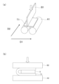
- FIG. 4(a) is a front view of a test member made by spot welding a hat-shaped member and a steel plate, which was manufactured for the axial crush test of the example.
- FIG. 4(b) is a perspective view of the test member shown in FIG. 4(a).
- FIG. 4(c) is a schematic diagram for explaining the axial crush test of the example.
- the steel plate of the present invention is a steel plate comprising a base steel plate, in which the base steel plate includes, in mass %, C: 0.030% or more and 0.250% or less, Si: 0.01% or more and 0.75% or less, and Mn. : 2.00% or more and less than 3.50%, P: 0.001% or more and 0.100% or less, S: 0.0200% or less, Al: 0.010% or more and 2.000% or less, N: 0. 0100% or less, with the balance consisting of Fe and unavoidable impurities, and the structure at the 1/4th thickness position of the base steel plate has a ferrite area ratio of less than 20.0%, and fresh martensite.
- area ratio of retained austenite 3.0% or less; area ratio of bainite and tempered bainite: more than 10.0% and 70.0% or less; area ratio: 30.0% or more and 80.0% or less, and furthermore, the average crystal grain size of island-like fresh martensite and island-like retained austenite in the bainite grains and tempered bainite grains is 2.00 ⁇ m or less.
- the average crystal grain size of carbides in bainite grains and tempered bainite grains is 500 nm or less, and the number density of carbides with a grain size of 300 nm or more in bainite grains and tempered bainite grains is 3.0 pieces/ ⁇ m 2 or less, the amount of diffusible hydrogen contained in the base steel sheet is 0.50 mass ppm or less, and the tensile strength is 1180 MPa or more.
- the steel plate may have a galvanized layer as the outermost layer on one or both sides of the steel plate.
- the steel sheet having a galvanized layer may be a galvanized steel sheet.
- compositions First, the composition of the base steel sheet of the steel sheet according to one embodiment of the present invention will be described. Note that the units in the component compositions are all “mass %”, but hereinafter, unless otherwise specified, they will simply be expressed as "%".
- C 0.030% or more and 0.250% or less C is an effective element for generating an appropriate amount of tempered martensite, bainite, tempered bainite, etc., and ensuring a TS of 1180 MPa or more, high YS, and high YR. It is.
- the C content is less than 0.030%, the area ratio of ferrite increases, making it difficult to increase the TS to 1180 MPa or more. It also causes a decrease in YS and YR.
- the C content exceeds 0.250%, the area ratio of fresh martensite increases, TS becomes excessively high, and El decreases.
- the C content is set to 0.030% or more and 0.250% or less.
- the C content is preferably 0.080% or more. Further, the C content is preferably 0.160% or less.
- Si 0.01% or more and 0.75% or less Si promotes ferrite transformation during annealing and during the cooling process after annealing. That is, Si is an element that affects the area ratio of ferrite. Here, if the Si content is less than 0.01%, the area ratio of ferrite decreases and ductility decreases.
- the Si content is set to 0.01% or more and 0.75% or less.
- the Si content is preferably 0.10% or more. Further, the Si content is preferably 0.70% or less.
- Mn 2.00% or more and less than 3.50%
- Mn is an element that adjusts the area ratio of tempered martensite, bainite, and further tempered bainite.
- the Mn content is less than 2.00%, the area ratio of ferrite increases and it becomes difficult to make the TS 1180 MPa or more. It also causes a decrease in YS and YR.
- the Mn content is 3.50% or more, the martensite transformation start temperature Ms (hereinafter also simply referred to as the Ms point or Ms) decreases, and the martensite generated in the first cooling step decreases.
- the Mn content is set to 2.00% or more and less than 3.50%.
- the Mn content is preferably 2.30% or more. Further, the Mn content is preferably 3.30% or less.
- P 0.001% or more and 0.100% or less
- P is an element that has a solid solution strengthening effect and increases the TS and YS of the steel sheet.
- the P content is set to 0.001% or more.
- P segregates at prior austenite grain boundaries and embrittles the grain boundaries. Therefore, during the V-bending test, voids are generated and cracks grow along the prior austenite grain boundaries, making it impossible to obtain the desired R/t.
- the P content is set to 0.001% or more and 0.100% or less.
- the P content is preferably 0.030% or less.
- S 0.0200% or less S exists as a sulfide in steel.
- the S content exceeds 0.0200%, voids are generated and cracks propagate starting from the sulfides during the V-bending test, making it impossible to obtain the desired R/t.
- the S content is set to 0.0200% or less.
- the S content is preferably 0.0080% or less. Note that although the lower limit of the S content is not particularly specified, it is preferable that the S content is 0.0001% or more due to constraints on production technology.
- Al 0.010% or more and 2.000% or less
- Al promotes ferrite transformation during annealing and during the cooling process after annealing. That is, Al is an element that affects the area ratio of ferrite.
- the Al content is set to 0.010% or more and 2.000% or less.
- Al content is preferably 0.015% or more. Further, the Al content is preferably 1.000% or less.
- N 0.0100% or less N exists as a nitride in steel.
- the N content exceeds 0.0100%, voids are generated and cracks propagate starting from the nitride during the V-bending test, making it impossible to obtain the desired R/t.
- the N content is set to 0.0100% or less.
- the N content is preferably 0.0050% or less. Note that, although the lower limit of the N content is not particularly specified, due to constraints on production technology, the N content is preferably 0.0005% or more.
- the basic component composition of the base steel plate of the steel plate according to one embodiment of the present invention has been described above.
- the base steel plate of the steel plate according to one embodiment of the present invention contains the above basic components, and the remainder other than the above basic components is Fe. (iron) and unavoidable impurities.
- the base steel sheet of the steel sheet according to one embodiment of the present invention contains the above-mentioned basic components, with the remainder consisting of Fe and inevitable impurities.
- the base steel sheet of the steel sheet according to an embodiment of the present invention may contain at least one selected from the following optional components.
- the effects of the present invention can be obtained for the optional components shown below as long as they are contained in amounts below the upper limit shown below, so no lower limit is set in particular.
- the following arbitrary elements are contained below the preferable lower limit value mentioned later, the said elements shall be contained as an unavoidable impurity.
- Nb 0.200% or less
- Ti 0.200% or less
- V 0.200% or less
- B 0.0100% or less
- Cr 1.000% or less
- Ni 1.000% or less
- Mo 1.000% or less
- Sb 0.200% or less
- Sn 0.200% or less
- Cu 1.000% or less
- Ta 0.100% or less
- W 0.500% or less
- Mg 0.200% or less
- Nb 0.200% or less
- Nb increases TS, YS, and YR by forming fine carbides, nitrides, or carbonitrides during hot rolling or annealing.
- the Nb content is 0.001% or more.
- the Nb content is more preferably 0.005% or more.
- the Nb content exceeds 0.200%, large amounts of coarse precipitates and inclusions may be formed. In such cases, coarse precipitates and inclusions become starting points for voids and cracks during hole expansion tests, V-bending tests, U-bending + close bending tests, or V-bending + orthogonal VDA bending tests. Desired ⁇ , R/t, ST and SFmax may not be obtained. Therefore, when Nb is contained, the Nb content is preferably 0.200% or less.
- the Nb content is more preferably 0.060% or less.
- Ti 0.200% or less Similar to Nb, Ti increases TS, YS, and YR by forming fine carbides, nitrides, or carbonitrides during hot rolling or annealing. In order to obtain such an effect, it is preferable that the Ti content is 0.001% or more. The Ti content is more preferably 0.005% or more. On the other hand, if the Ti content exceeds 0.200%, large amounts of coarse precipitates and inclusions may be generated. In such cases, coarse precipitates and inclusions become starting points for voids and cracks during hole expansion tests, V-bending tests, U-bending + close bending tests, or V-bending + orthogonal VDA bending tests. Desired ⁇ , R/t, ST and SFmax may not be obtained. Therefore, when containing Ti, the Ti content is preferably 0.200% or less. The Ti content is more preferably 0.060% or less.
- V 0.200% or less
- V increases TS and YS by forming fine carbides, nitrides, or carbonitrides during hot rolling or annealing.
- the V content is 0.001% or more.
- the V content is more preferably 0.005% or more.
- the V content is more preferably 0.010% or more, and even more preferably 0.030% or more.
- the V content exceeds 0.200%, large amounts of coarse precipitates and inclusions may be generated. In such cases, coarse precipitates and inclusions become starting points for voids and cracks during hole expansion tests, V-bending tests, U-bending + close bending tests, or V-bending + orthogonal VDA bending tests. Desired ⁇ , R/t, ST and SFmax may not be obtained. Therefore, when V is contained, the V content is preferably 0.200% or less.
- the V content is more preferably 0.060% or less.
- B 0.0100% or less
- B is an element that improves hardenability by segregating at austenite grain boundaries. Further, B is an element that controls the generation and grain growth of ferrite during cooling after annealing. In order to obtain such an effect, it is preferable that the B content is 0.0001% or more. The B content is more preferably 0.0002% or more. The B content is more preferably 0.0005% or more, and even more preferably 0.0007% or more. On the other hand, if the B content exceeds 0.0100%, cracks may occur inside the steel sheet during hot rolling.
- the B content is preferably 0.0100% or less.
- the B content is more preferably 0.0050% or less.
- the Cr content is preferably 0.0005% or more. Further, the Cr content is more preferably 0.010% or more. Cr is more preferably 0.030% or more, and even more preferably 0.050% or more. On the other hand, if the Cr content exceeds 1.000%, the area ratio of fresh martensite increases, hole expandability and V-bending test bendability decrease, and the desired ⁇ and R/t may not be obtained. There is. Therefore, when Cr is contained, the Cr content is preferably 1.000% or less. Further, the Cr content is more preferably 0.800% or less, still more preferably 0.700% or less.
- Ni 1.000% or less
- Ni is an element that improves hardenability, and the addition of Ni produces a large amount of tempered martensite, thereby increasing TS, YS, and YR.
- the Ni content be 0.005% or more.
- the Ni content is more preferably 0.020% or more.
- the Ni content is more preferably 0.040% or more, and even more preferably 0.060% or more.
- the Ni content exceeds 1.000%, the area ratio of fresh martensite increases, hole expandability and V-bending test bendability decrease, and the desired ⁇ and R/t may not be obtained. There is. Therefore, when Ni is contained, the Ni content is preferably 1.000% or less.
- the Ni content is more preferably 0.800% or less.
- the Ni content is more preferably 0.600% or less, and even more preferably 0.400% or less.
- Mo 1.000% or less
- Mo is an element that improves hardenability, and the addition of Mo generates a large amount of tempered martensite, thereby increasing TS, YS, and YR.
- the Mo content is 0.010% or more.
- Mo content is more preferably 0.030% or more.
- the Mo content exceeds 1.000%, the area ratio of fresh martensite increases, the hole expandability and the bendability in the V-bending test decrease, and the desired ⁇ and R/t may not be obtained. There is. Therefore, when Mo is contained, the Mo content is preferably 1.000% or less.
- the Mo content is more preferably 0.500% or less, still more preferably 0.450% or less, and even more preferably 0.400% or less.
- the Mo content is more preferably 0.350% or less, and even more preferably 0.300% or less.
- Sb 0.200% or less
- Sb is an effective element for suppressing the diffusion of C near the surface of the steel sheet during annealing and controlling the formation of a soft layer near the surface of the steel sheet. If the soft layer increases excessively near the surface of the steel sheet, it may be difficult to increase the TS to 1180 MPa or more. Furthermore, there is a possibility that YS will be lowered. Therefore, it is preferable that the Sb content is 0.002% or more. The Sb content is more preferably 0.005% or more. On the other hand, when the Sb content exceeds 0.200%, a soft layer is not formed near the surface of the steel sheet, which may lead to a decrease in ⁇ , R/t, ST, and SFmax. Therefore, when Sb is contained, the Sb content is preferably 0.200% or less. The Sb content is more preferably 0.020% or less.
- Sn 0.200% or less
- Sn is an effective element for suppressing the diffusion of C near the surface of the steel sheet during annealing and controlling the formation of a soft layer near the surface of the steel sheet. If the soft layer increases excessively near the surface of the steel sheet, it may be difficult to increase the TS to 1180 MPa or more. Furthermore, there is a possibility that YS will be lowered. Therefore, it is preferable that the Sn content is 0.002% or more. The Sn content is more preferably 0.005% or more. On the other hand, if the Sn content exceeds 0.200%, a soft layer will not be formed near the surface of the steel sheet, which may cause a decrease in ⁇ , R/t, ST, and SFmax. Therefore, when Sn is contained, the Sn content is preferably 0.200% or less. The Sn content is more preferably 0.020% or less.
- Cu 1.000% or less
- Cu is an element that improves hardenability, and the addition of Cu generates a large amount of tempered martensite, thereby increasing TS, YS, and YR.
- the Cu content is 0.005% or more.
- the Cu content is more preferably 0.008% or more, and even more preferably 0.010% or more.
- the Cu content is more preferably 0.020% or more.
- the area ratio of fresh martensite may increase excessively. Further, a large amount of coarse precipitates and inclusions may be generated.
- the Cu content is preferably 1.000% or less.
- the Cu content is more preferably 0.200% or less.
- Ta 0.100% or less Like Ti, Nb, and V, Ta increases TS, YS, and YR by forming fine carbides, nitrides, or carbonitrides during hot rolling and annealing. let In addition, Ta is partially dissolved in Nb carbides and Nb carbonitrides to form composite precipitates such as (Nb, Ta) (C, N). This suppresses coarsening of precipitates and stabilizes precipitation strengthening. This further improves TS and YS. In order to obtain such an effect, the Ta content is preferably 0.001% or more. The Ta content is more preferably 0.002% or more, and even more preferably 0.004% or more.
- the Ta content is preferably 0.100% or less.
- the Ta content is more preferably 0.090% or less, and even more preferably 0.080% or less.
- W 0.500% or less
- W is an element that improves hardenability, and the addition of W generates a large amount of tempered martensite, thereby increasing TS, YS, and YR.
- the W content is 0.001% or more.
- the W content is more preferably 0.030% or more.
- the W content exceeds 0.500%, the area ratio of fresh martensite increases, hole expandability and V-bending test bendability decrease, and the desired ⁇ and R/t may not be obtained. There is. Therefore, when W is contained, the W content is preferably 0.500% or less.
- the W content is more preferably 0.450% or less, still more preferably 0.400% or less. It is even more preferable that the W content is 0.300% or less.
- Mg 0.0200% or less
- Mg is an effective element for making inclusions such as sulfides and oxides spheroidal and improving the hole expandability and bendability of the steel sheet.
- the Mg content is 0.0001% or more.
- the Mg content is more preferably 0.0005% or more, and even more preferably 0.0010% or more.
- the Mg content exceeds 0.0200%, large amounts of coarse precipitates and inclusions may be formed. In such cases, excessively coarse precipitates and inclusions become starting points for voids and cracks during hole expansion tests, V-bending tests, U-bending + close bending tests, or V-bending + orthogonal VDA bending tests.
- the Mg content is preferably 0.0200% or less.
- the Mg content is more preferably 0.0180% or less, and even more preferably 0.0150% or less.
- Zn 0.0200% or less
- Zn is an effective element for spheroidizing the shape of inclusions and improving the hole expandability and bendability of the steel sheet.
- the Zn content is preferably 0.0010% or more.
- the Zn content is more preferably 0.0020% or more, and even more preferably 0.0030% or more.
- the Zn content exceeds 0.0200%, large amounts of coarse precipitates and inclusions may be formed. In such cases, excessively coarse precipitates and inclusions become starting points for voids and cracks during hole expansion tests, V-bending tests, U-bending + close bending tests, or V-bending + orthogonal VDA bending tests.
- the Zn content is preferably 0.0200% or less.
- the Zn content is more preferably 0.0180% or less, and even more preferably 0.0150% or less.
- Co 0.0200% or less
- Co is an effective element for spheroidizing the shape of inclusions and improving the hole expandability and bendability of the steel sheet.
- the Co content is preferably 0.0010% or more.
- the Co content is more preferably 0.0020% or more, and even more preferably 0.0030% or more.
- the Co content exceeds 0.0200%, large amounts of coarse precipitates and inclusions may be formed. In such cases, excessively coarse precipitates and inclusions become starting points for voids and cracks during hole expansion tests, V-bending tests, U-bending + close bending tests, or V-bending + orthogonal VDA bending tests.
- the Co content is preferably 0.0200% or less.
- the Co content is more preferably 0.0180% or less, and even more preferably 0.0150% or less.
- Zr 0.1000% or less
- Zr is an effective element for spheroidizing the shape of inclusions and improving the hole expandability and bendability of the steel sheet.
- the Zr content is preferably 0.0010% or more.
- the Zr content exceeds 0.1000%, excessively coarse precipitates and inclusions may occur during the hole expansion test, V-bending test, U-bending + close bending test, or V-bending + During the orthogonal VDA bending test, the desired ⁇ , R/t, ST and SFmax may not be obtained because it becomes a starting point for voids and cracks. Therefore, when Zr is contained, the Zr content is preferably 0.1000% or less.
- the Zr content is more preferably 0.0300% or less, and even more preferably 0.0100% or less.
- Ca 0.0200% or less Ca exists as inclusions in steel.
- the Ca content is preferably 0.0200% or less.
- the Ca content is preferably 0.0020% or less.
- the Ca content is more preferably 0.0019% or less, and even more preferably 0.0018% or less.
- the lower limit of the Ca content is not particularly limited, but the Ca content is preferably 0.0005% or more.
- the Ca content is more preferably 0.0010% or more.
- Se 0.0200% or less, Te: 0.0200% or less, Ge: 0.0200% or less, As: 0.0500% or less, Sr: 0.0200% or less, Cs: 0.0200% or less, Hf: 0.0200% or less, Pb: 0.0200% or less, Bi: 0.0200% or less, and REM: 0.0200% or less Se, Te, Ge, As, Sr, Cs, Hf, Pb, Bi, and REM are all is also an effective element for improving the hole expandability and bendability of steel sheets. In order to obtain such an effect, it is preferable that the content of Se, Te, Ge, As, Sr, Cs, Hf, Pb, Bi, and REM is each 0.0001% or more.
- the REM content is preferably 0.0200% or less, and the As content is preferably 0.0500% or less.
- the Se content is more preferably 0.0005% or more, and even more preferably 0.0008% or more.
- the Se content is more preferably 0.0180% or less, and even more preferably 0.0150% or less.
- the Te content is more preferably 0.0005% or more, and even more preferably 0.0008% or more.
- the Te content is more preferably 0.0180% or less, and even more preferably 0.0150% or less.
- the Ge content is more preferably 0.0005% or more, and even more preferably 0.0008% or more.
- the Ge content is more preferably 0.0180% or less, and even more preferably 0.0150% or less.
- As content it is more preferred that it is 0.0010% or more, and it is still more preferred that it is 0.0015% or more.
- As content it is more preferred that it is 0.0400% or less, and it is still more preferred that it is 0.0300% or less.
- the Sr content is more preferably 0.0005% or more, and even more preferably 0.0008% or more.
- the Sr content is more preferably 0.0180% or less, and even more preferably 0.0150% or less.
- the Cs content is more preferably 0.0005% or more, and even more preferably 0.0008% or more.
- the Cs content is more preferably 0.0180% or less, and even more preferably 0.0150% or less.
- the Hf content is more preferably 0.0005% or more, and even more preferably 0.0008% or more.
- the Hf content is more preferably 0.0180% or less, and even more preferably 0.0150% or less.
- the Pb content is more preferably 0.0005% or more, and even more preferably 0.0008% or more.
- the Pb content is more preferably 0.0180% or less, and even more preferably 0.0150% or less.
- the Bi content is more preferably 0.0005% or more, and even more preferably 0.0008% or more.
- Bi is more preferably 0.0180% or less, and even more preferably 0.0150% or less.
- REM is more preferably 0.0005% or more, and even more preferably 0.0008% or more.
- REM is more preferably 0.0180% or less, and even more preferably 0.0150% or less.
- REM as used in the present invention refers to scandium (Sc) with atomic number 21, yttrium (Y) with atomic number 39, and lanthanum (La) with atomic number 57 to lutetium (Lu) with atomic number 71. Refers to lanthanoids.
- the REM concentration in the present invention is the total content of one or more elements selected from the above-mentioned REMs.
- REM is not particularly limited, but is preferably Sc, Y, Ce, or La.
- Ferrite area ratio less than 20.0% (including 0.0%) If the area ratio of ferrite increases excessively, it becomes difficult to increase the TS to 1180 MPa or more. It also causes a decrease in YS and YR. Therefore, the area ratio of ferrite is less than 20.0% (including 0.0%). Further, the area ratio of ferrite is preferably 15.0% or less.
- Fresh martensite area ratio 15.0% or less (including 0.0%)
- the area ratio of fresh martensite is set to 15.0% or less.
- the area ratio of fresh martensite is preferably 10.0% or less. Note that the lower limit of the area ratio of fresh martensite is not particularly limited, and may be 0.0%.
- the fresh martensite referred to here is martensite that is still quenched (not tempered).
- the fresh martensite referred to herein also includes (isolated) island-like fresh martensite within bainite grains and tempered bainite grains, which will be described later.
- Area ratio of retained austenite 3.0% or less (including 0.0%)
- the area ratio of retained austenite is set to 3.0% or less.
- the area ratio of retained austenite is preferably 2.5% or less, more preferably 2.0% or less.
- the lower limit of the area ratio of retained austenite is not particularly limited, but is preferably 0.1% or more, more preferably 0.2% or more.
- the retained austenite herein also includes (isolated) island-like retained austenite within bainite grains and tempered bainite grains, which will be described later.
- a tension of 2.0 kgf/mm 2 or more is applied to the steel plate in a temperature range of 300°C or more and 450°C or less, and then the steel plate is heated to a diameter of 500 mm or more per pass.
- untransformed austenite undergoes deformation-induced transformation and becomes fresh martensite, and in the subsequent reheating process, the fresh martensite is transformed into fresh martensite.
- the desired area ratio of tempered martensite can be secured. It becomes possible.
- Bainite is a structure generated in the first cooling step and intermediate holding step, as shown in FIG.
- the tempered bainite (BT) referred to here is a structure in which the bainite generated in the reheating process has been tempered, as shown in FIG.
- F ferrite
- M martensite
- RA retained austenite
- TM tempered martensite
- ⁇ carbide.
- the area ratio of bainite and tempered bainite is made to be more than 10.0%.
- the area ratio of bainite and tempered bainite increases excessively to more than 70.0%, it becomes difficult to secure a TS of 1180 MPa or more. Therefore, the area ratio of bainite and tempered bainite is 70.0% or less. Further, the area ratio of bainite and tempered bainite is preferably 15.0% or more. Further, the area ratio of bainite and tempered bainite is preferably 65.0% or less.
- Tempered martensite is a structure obtained in a reheating process.
- the hard second phase fresh martensite + retained austenite
- the area ratio of martensite must be 15.0% or less, and the volume ratio of retained austenite must be 3.0% or less.
- a tension of 2.0 kgf/mm2 or more is applied in a temperature range of 300°C or more and 450°C or less, and then the steel plate is By passing 5 or more passes while contacting the roll for 1/4 rotation of the roll, untransformed austenite undergoes deformation-induced transformation and becomes fresh martensite, and in the subsequent reheating process, the fresh martensite is tempered and tempered. It becomes martensite. That is, the above-mentioned tempered martensite has a structure necessary to obtain desired ⁇ , R/t, ST and SFmax. Therefore, the area ratio of tempered martensite is set to 30.0% or more.
- the area ratio of tempered martensite is preferably 35.0% or more.
- the area ratio of tempered martensite increases too much, the desired area ratio of bainite and tempered bainite cannot be obtained, and it becomes difficult to ensure good ductility, that is, to obtain the desired El. Therefore, the area ratio of tempered martensite is 70.0% or less.
- the area ratio of tempered martensite is preferably 60.0% or less.
- Average grain size of island-like fresh martensite and island-like retained austenite in bainite grains and tempered bainite grains 2.00 ⁇ m or less
- isolated island-like fresh martensite in bainite grains and tempered bainite grains When the average grain size of the isolated island-like retained austenite is small, it is possible to further suppress the generation of voids while ensuring a TS of 1180 MPa or more, and to obtain better ⁇ , R/t, ST and SFmax. Therefore, the average crystal grain size of isolated island-like fresh martensite and isolated island-like retained austenite in bainite grains and tempered bainite grains is set to 2.00 ⁇ m or less.
- the average crystal grain size of isolated island-like fresh martensite in bainite grains and tempered bainite grains and isolated island-like retained austenite is the same as that of island-like fresh martensite in bainite grains and tempered bainite grains. and the average grain size of the island-like retained austenite. That is, in the present invention, the average crystal grain size of island-like fresh martensite and island-like retained austenite in bainite grains and tempered bainite grains is set to 2.00 ⁇ m or less. Further, the average crystal grain size of the island-like fresh martensite and the island-like retained austenite in the bainite grains and in the tempered bainite grains is preferably 1.00 ⁇ m or less.
- the average crystal grain size of island-like fresh martensite and island-like retained austenite in bainite grains and tempered bainite grains is preferably 0.10 ⁇ m or more, more preferably 0.20 ⁇ m or more. be.
- Average grain size of carbides in bainite grains and tempered bainite grains 500 nm or less
- the average crystal grain size of carbides within the bainite grains and within the tempered bainite grains is set to 500 nm or less.
- the average crystal grain size of carbides within the bainite grains and within the tempered bainite grains is preferably 300 nm or less.
- the average crystal grain size of carbides in bainite grains and tempered bainite grains is preferably 50 nm or more, more preferably 80 nm or more.
- Number density of carbides with a grain size of 300 nm or more in bainite grains and tempered bainite grains 3.0 pieces/ ⁇ m 2 or less
- the number of carbides with a grain size of 300 nm or more in bainite grains and tempered bainite grains is set to 3.0 pieces/ ⁇ m 2 or less.
- the number density of carbides having a grain size of 300 nm or more in the bainite grains and tempered bainite grains is preferably 2.5 carbides/ ⁇ m 2 or less.
- the lower limit is not particularly limited, the number density of carbides within the bainite grains and within the tempered bainite grains is preferably 0.2 pieces/ ⁇ m 2 or more, more preferably 0.5 pieces/ ⁇ m 2 or more.
- the area ratio of the remaining structures other than the aforementioned ferrite, fresh martensite, retained austenite, bainite, tempered bainite, and tempered martensite is preferably 10.0% or less.
- the area ratio of the remaining tissue is more preferably 5.0% or less. Further, the area ratio of the remaining tissue may be 0.0%.
- the residual structure is not particularly limited, and examples thereof include unrecrystallized ferrite and pearlite.
- the type of residual tissue can be confirmed, for example, by observation using a scanning electron microscope (SEM).
- the area ratio of ferrite, bainite, tempered bainite, tempered martensite, and hard second phase is measured as follows at the 1/4 thickness position of the base steel plate. That is, the sample is cut out so that the plate thickness cross section (L cross section) parallel to the rolling direction of the steel plate serves as the observation surface. Next, the observation surface of the sample is polished with diamond paste, and then final polished with alumina. Next, the observation surface of the sample was exposed to 3 vol. % nital to reveal the tissue. Next, the observation position is set at 1/4 of the thickness of the steel plate, and 5 fields of view are observed using an SEM at a magnification of 3000 times.
- the area of each constituent structure (ferrite, bainite, tempered bainite, tempered martensite, and hard second phase (fresh martensite + retained austenite)) was measured using Adobe Photoshop from Adobe Systems. The area ratio divided by is calculated for five fields of view, and these values are averaged to determine the area ratio of each tissue.
- Ferrite A black region with a block-like shape. In addition, it contains almost no carbide. Furthermore, isolated island-like fresh martensite and isolated island-like retained austenite within the ferrite grains are not included in the area ratio of ferrite.
- Bainite and tempered bainite A black to dark gray area, with a lumpy or irregular shape. It also contains a relatively small amount of carbide.
- Tempered martensite A gray area with an amorphous shape. It also contains a relatively large number of carbides. Hard second phase (retained austenite + fresh martensite): This is a white to light gray region with an amorphous shape. Also, it does not contain carbide. Carbide: A white region with a dotted or linear shape. It is included in bainite, tempered bainite, and tempered martensite. Residual structure: Examples include the above-mentioned unrecrystallized ferrite and pearlite, and their forms are known.
- isolated island-like fresh martensite and isolated island-like retained austenite inside bainite grains and tempered bainite grains were extracted by hand, and the images were extracted using open source ImageJ.
- the average grain size of isolated island-like fresh martensite and isolated island-like retained austenite in bainite grains and tempered bainite grains is determined.
- the above average grain size is determined by dividing the total area of island-like fresh martensite and island-like retained austenite by the number of island-like fresh martensite and island-like retained austenite to find the average area, and then dividing the above average area into a circle.
- the equivalent circle diameter obtained by dividing by the periodicity ⁇ and multiplying the square root by 2 is defined as the average crystal grain size.
- the outer periphery is surrounded by bainite and/or tempered bainite, and the island-like region is formed integrally without interruption. Measure as one piece.
- the carbides inside the bainite grains and tempered bainite grains were extracted by hand, and using open source ImageJ, the inside of the bainite grains and tempered bainite grains were extracted.
- the average grain size of carbides and the number density of carbides with a grain size of 300 nm or more among the carbides in the bainite grains and tempered bainite grains are determined.
- the above average grain size is calculated by dividing the total area of carbides by the number of carbides to find the average area, dividing the above average area by pi, and multiplying the square root of the circle by 2.
- the equivalent diameter is taken as the average grain size.
- an island-like region whose outer periphery is surrounded by bainite and/or tempered bainite and is integrally formed without interruption is measured as one.
- the area ratio of retained austenite is measured as follows. That is, the base steel plate is mechanically ground in the thickness direction (depth direction) to a position of 1/4 of the plate thickness, and then chemically polished with oxalic acid to form an observation surface. Then, the observation surface is observed by X-ray diffraction. MoK ⁇ rays were used for the incident X-rays, and the diffraction intensity of the (200), (211) and (220) planes of BCC iron was compared with the (200), (220) and (311) planes of FCC iron (austenite). The ratio of the diffraction intensities of each surface is determined, and the volume fraction of retained austenite is calculated from the ratio of the diffraction intensities of each surface. Then, assuming that the retained austenite is three-dimensionally homogeneous, the volume fraction of the retained austenite is defined as the area fraction of the retained austenite.
- the area ratio of fresh martensite is determined by subtracting the area ratio of retained austenite from the area ratio of the hard second phase determined as described above.
- [Area ratio of fresh martensite (%)] [Area ratio of hard second phase (%)] - [Area ratio of retained austenite (%)]
- Amount of diffusible hydrogen (in steel) contained in the base steel sheet 0.50 mass ppm or less
- the amount of diffusible hydrogen in the steel sheet exceeds 0.50 mass ppm, the desired ⁇ , R/t, ST and SFmax I can't get it.
- the amount of diffusible hydrogen in the steel sheet is preferably 0.25 mass ppm or less.
- the lower limit of the amount of diffusible hydrogen in the steel sheet is not particularly specified, it is preferable that the amount of diffusible hydrogen in the steel sheet is 0.01 mass ppm or more due to constraints on production technology.
- the base steel plate for measuring the amount of diffusible hydrogen may be a high-strength steel plate before plating treatment, or a base steel plate of high-strength galvanized steel sheet after galvanizing treatment and before processing.
- it may be a base steel plate of a steel plate that has been subjected to processes such as punching and stretch flange forming after galvanizing, or it may be a base part of a product manufactured by welding the processed steel plate. I don't mind.
- the method for measuring the amount of diffusible hydrogen in a steel sheet is as follows. A test piece with a length of 30 mm and a width of 5 mm is taken, and if a galvanized layer is formed on the steel sheet, the hot-dip galvanized layer or the alloyed hot-dip galvanized layer is removed with alkali. Thereafter, the amount of hydrogen released from the test piece is measured by temperature programmed desorption analysis. Specifically, after continuously heating from room temperature (-5 to 55°C) to 300°C at a heating rate of 200°C/h, cooling to room temperature, and measuring the cumulative amount of hydrogen released from the test piece from room temperature to 210°C. The amount is measured and taken as the amount of diffusible hydrogen in the steel sheet.
- the room temperature should be within the range of local temperature changes over a one-year period, taking into account production in various countries around the world. Generally, the temperature is preferably in the range of 10 to 50°C.
- the base steel sheet of the steel plate according to one embodiment of the present invention preferably has a soft surface layer on the surface of the base steel sheet.
- the soft surface layer contributes to suppressing the propagation of bending cracks during press molding and car body collisions, further improving the bending fracture resistance.
- the surface soft layer means a decarburized layer, and is a surface layer region having a Vickers hardness of 85% or less of the Vickers hardness of the cross section at the 1/4 thickness position.
- the surface soft layer is formed in an area of 200 ⁇ m or less in the thickness direction from the surface of the base steel sheet.
- the area where the surface soft layer is formed is preferably 150 ⁇ m or less, more preferably 120 ⁇ m or less in the thickness direction from the base steel plate surface.
- the lower limit of the thickness of the surface soft layer is not particularly determined, it is preferably 7 ⁇ m or more, and more preferably more than 14 ⁇ m.
- the surface soft layer preferably has a thickness of 30 ⁇ m or more, more preferably 40 ⁇ m or more.
- the position of 1/4 of the thickness of the base steel plate at which the Vickers hardness is measured is a non-surface soft layer (a layer that does not satisfy the hardness conditions of the surface soft layer defined in the present invention). Vickers hardness is measured based on JIS Z 2244-1 (2020) with a load of 10 gf.
- Nano-hardness of surface soft layer 300 points in an area of 50 ⁇ m x 50 ⁇ m on the plate surface at 1/4 position and 1/2 depth in the thickness direction of the surface soft layer from the surface of the base steel plate, respectively.
- the proportion of measurements where the nanohardness of the plate surface at 1/4 of the depth in the thickness direction of the surface soft layer from the surface of the base steel sheet was 7.0 GPa or more was determined by the thickness of the surface soft layer.
- the present invention in order to obtain excellent bendability during press forming and excellent bending rupture characteristics during collision, it is necessary to When nanohardness was measured at 300 points or more in an area of 50 ⁇ m x 50 ⁇ m on the board surface at 1/4 depth in the thickness direction and 1/2 depth in the thickness direction of the surface soft layer, The percentage of measurements where the nanohardness of the sheet surface at 1/4 of the depth in the thickness direction of the surface soft layer from the steel sheet surface is 7.0 GPa or more is It is preferable that it is 0.10 or less with respect to the number of measurements.
- the ratio of nanohardness of 7.0 GPa or more is 0.10 or less, it means that the ratio of hard structures (martensite, etc.), inclusions, etc. is small; It becomes possible to further suppress the generation and connection of voids during press molding and collision, as well as the propagation of cracks, resulting in excellent R/t and SFmax.
- the standard deviation ⁇ of the nano-hardness of the plate surface at a position 1/4 of the depth in the thickness direction of the surface soft layer from the steel plate surface is 1.8 GPa or less, and The standard deviation ⁇ of the nanohardness of the plate surface at the 1/2 position is 2.2 GPa or less.
- the standard deviation ⁇ of the nano-hardness of the plate surface at 1/4 of the depth in the thickness direction of the soft layer is 1.8 GPa or less, and furthermore, the standard deviation ⁇ of the nanohardness of the plate surface at 1/4 of the depth in the thickness direction of the surface soft layer from the steel plate surface is 1/2 of the depth in the thickness direction of the surface soft layer.
- the standard deviation ⁇ of the nanohardness of the plate surface is 2.2 GPa or less.
- the standard deviation ⁇ of the nano-hardness of the plate surface at a position 1/4 of the depth in the thickness direction of the surface soft layer from the steel plate surface is 1.8 GPa or less, and If the standard deviation ⁇ of the nanohardness of the plate surface at the 1/2 position is 2.2 GPa or less, it means that the difference in microstructure hardness in the micro region is small, and it is difficult to prevent the formation and connection of voids during press forming and collision. It becomes possible to further suppress the propagation of cracks, and excellent R/t and SFmax can be obtained.
- a preferable range of the standard deviation ⁇ of the nanohardness of the plate surface at a position 1/4 of the thickness direction depth of the surface soft layer from the base steel plate surface is preferably 1.7 GPa or less.
- the standard deviation ⁇ of the nanohardness of the plate surface at a position of 1/4 of the thickness direction depth of the surface soft layer from the base steel plate surface is more preferably 1.3 GPa or less.
- the standard deviation ⁇ of the nanohardness of the plate surface at a position 1/4 of the thickness direction depth of the surface soft layer from the base steel plate surface may be 0.5 GPa or more.
- a more preferable range of the standard deviation ⁇ of the nano-hardness of the plate surface at 1/2 the thickness direction depth of the surface soft layer from the base steel plate surface is 2.1 GPa or less.
- the standard deviation ⁇ of the nanohardness of the plate surface at a position 1/2 the thickness direction depth of the surface soft layer from the base steel plate surface is more preferably 1.7 GPa or less.
- the lower limit is not particularly limited, the standard deviation ⁇ of the nanohardness of the plate surface at a position 1/2 the thickness direction depth of the surface soft layer from the base steel plate surface may be 0.6 GPa or more.
- the nanohardness of the plate surface at the 1/4 position and 1/2 position of the depth in the thickness direction is the hardness measured by the following method.
- the plating layer to be peeled off is a galvanized layer if a galvanized layer is formed, a metal plating layer if a metal plating layer is formed, and a galvanized layer and a metal plating layer. If it is formed, it is a zinc plating layer and a metal plating layer.
- Nanohardness is measured using Hysitron's tribo-950 with a Berkovich-shaped diamond indenter under the conditions of load: 500 ⁇ N, measurement area: 50 ⁇ m ⁇ 50 ⁇ m, and dot spacing: 2 ⁇ m. Further, mechanical polishing is performed to 1/2 the depth in the thickness direction of the surface soft layer, buff polishing with diamond and alumina, and further colloidal silica polishing.
- Nanohardness is measured using Hysitron's tribo-950 with a Berkovich-shaped diamond indenter under the conditions of load: 500 ⁇ N, measurement area: 50 ⁇ m ⁇ 50 ⁇ m, and dot spacing: 2 ⁇ m.
- Nanohardness is measured at 300 or more points at a position of 1/4 of the depth in the thickness direction, and nanohardness at 300 or more points is also measured at a position of 1/2 of the depth in the thickness direction. For example, when the soft surface layer thickness is 100 ⁇ m, the 1/4 position is 25 ⁇ m from the surface of the soft surface layer, and the 1/2 position is 50 ⁇ m from the surface of the soft surface layer. Nanohardness is measured at 300 or more points at this 25 ⁇ m position, and nanohardness at 300 or more points is also measured at the 50 ⁇ m position.
- the steel sheet according to an embodiment of the present invention has a metal plating layer (first plating layer, pre-plating layer) (note that the metal plating layer (first plating layer) is , a hot-dip galvanized layer, and an alloyed hot-dip galvanized layer (excluding the galvanized layer).
- the metal plating layer is preferably a metal electroplating layer, and below, the metal electroplating layer will be explained as an example.
- the thickness of the soft layer can be increased, and the axial crushing properties can be made very excellent.
- the present invention by having a metal plating layer, even if the dew point is ⁇ 20° C. or lower and the soft layer thickness is small, the same axial crushing characteristics as when the soft layer thickness is large can be obtained.
- the metal species of the metal electroplating layer include Cr, Mn, Fe, Co, Ni, Cu, Ga, Ge, As, Ru, Rh, Pd, Ag, Cd, In, Sn, Sb, Os, Ir, Rt, Any of Au, Hg, Ti, Pb, and Bi may be used, but Fe is more preferable.
- an Fe-based electroplated layer will be explained as an example, but the following conditions for Fe can be similarly adopted for other metal types.
- the amount of the Fe-based electroplated layer deposited is more than 0 g/m 2 , preferably 2.0 g/m 2 or more.
- the upper limit of the amount of the Fe-based electroplated layer per side is not particularly limited, but from the viewpoint of cost, it is preferable that the amount of the Fe-based electroplated layer applied per side is 60 g/m 2 or less.
- the amount of the Fe-based electroplated layer deposited is preferably 50 g/m 2 or less, more preferably 40 g/m 2 or less, and even more preferably 30 g/m 2 or less.
- the adhesion amount of the Fe-based electroplating layer is measured as follows. A sample with a size of 10 x 15 mm is taken from a Fe-based electroplated steel plate and embedded in resin to form a cross-sectional embedded sample. Three arbitrary points on the same cross section were observed using a scanning electron microscope (SEM) at an accelerating voltage of 15 kV and a magnification of 2,000 to 10,000 times depending on the thickness of the Fe-based plating layer. By multiplying the average value by the specific gravity of iron, it is converted into the amount of Fe-based electroplating layer deposited on one side.
- SEM scanning electron microscope
- Fe-based electroplating layers include Fe-B alloy, Fe-C alloy, Fe-P alloy, Fe-N alloy, Fe-O alloy, Fe-Ni alloy, Fe-Mn alloy, Fe- An alloy plating layer such as Mo alloy or Fe-W alloy can be used.
- the composition of the Fe-based electroplated layer is not particularly limited, but 1 selected from the group consisting of B, C, P, N, O, Ni, Mn, Mo, Zn, W, Pb, Sn, Cr, V, and Co.
- the composition contains two or more elements in a total of 10% by mass or less, with the remainder consisting of Fe and unavoidable impurities.
- the C content is preferably 0.08% by mass or less.
- Tensile strength (TS) 1180 MPa or more
- the tensile strength of the steel plate according to one embodiment of the present invention is 1180 MPa or more.
- the yield stress (YS), yield ratio (YR), total elongation (El), critical hole expansion rate ( ⁇ ), critical spacer thickness in U bending + close contact bending test ( The reference value of the stroke at maximum load (SFmax) in the ST) and V-bending + orthogonal VDA bending tests, and the presence or absence of fracture (appearance cracking) in the axial crushing test are as described above.
- tensile strength (TS), yield stress (YS), yield ratio (YR), and total elongation (El) are measured by a tensile test in accordance with JIS Z 2241 (2011) described later in Examples.
- the critical hole expansion rate ( ⁇ ) is measured by a hole expansion test based on JIS Z 2256 (2020), which will be described later in Examples.
- the critical spacer thickness (ST) is measured by the U-bending + close-contact bending test described later in Examples.
- the stroke (SFmax) at maximum load in the V-bending + orthogonal VDA bending test is measured by the V-bending + orthogonal VDA bending test described later in the Examples.
- the presence or absence of fracture (appearance cracking) in the axial crushing test is determined by the axial crushing test described later in Examples.
- Galvanized layer (second plating layer)
- a steel sheet according to an embodiment of the present invention has a galvanized layer formed on the base steel sheet (on the surface of the base steel sheet or on the surface of the metal plating layer if a metal plating layer is formed) as the outermost layer.
- this galvanized layer may be provided only on one surface of the base steel sheet, or may be provided on both surfaces.
- the steel sheet having a galvanized layer may be a galvanized steel sheet. That is, the steel sheet of the present invention has a base steel plate, and a second plating layer (a galvanized layer, an aluminum plating layer, etc.) may be formed on the base steel plate.
- a metal plating layer (a first plating layer (excluding the second plating layer of the galvanized layer)) and a second plating layer (a zinc plating layer, an aluminum plating layer, etc.) may be formed in this order on the base steel sheet.
- the galvanized layer here refers to a plating layer containing Zn as a main component (Zn content is 50.0% or more), and includes, for example, a hot-dip galvanized layer and an alloyed hot-dip galvanized layer.
- the hot-dip galvanized layer is preferably composed of, for example, Zn, 20.0% by mass or less of Fe, and 0.001% by mass or more and 1.0% by mass or less of Al.
- the hot-dip galvanized layer may optionally include one selected from the group consisting of Pb, Sb, Si, Sn, Mg, Mn, Ni, Cr, Co, Ca, Cu, Li, Ti, Be, Bi, and REM.
- the total content of a species or two or more elements may be 0.0% by mass or more and 3.5% by mass or less.
- the Fe content of the hot-dip galvanized layer is more preferably less than 7.0% by mass. Note that the remainder other than the above elements are unavoidable impurities.
- the alloyed hot-dip galvanized layer is preferably composed of, for example, Zn, 20.0% by mass or less of Fe, and 0.001% by mass or more and 1.0% by mass or less of Al. Additionally, the alloyed hot-dip galvanized layer may optionally be selected from the group consisting of Pb, Sb, Si, Sn, Mg, Mn, Ni, Cr, Co, Ca, Cu, Li, Ti, Be, Bi, and REM. One or more types of elements may be contained in a total amount of 0.0% by mass or more and 3.5% by mass or less.
- the Fe content of the alloyed hot-dip galvanized layer is more preferably 7.0% by mass or more, and still more preferably 8.0% by mass or more. Further, the Fe content of the alloyed hot-dip galvanized layer is more preferably 15.0% by mass or less, still more preferably 12.0% by mass or less. Note that the remainder other than the above elements are unavoidable impurities.
- the amount of plating deposited on one side of the galvanized layer is not particularly limited, but is preferably 20 g/m 2 or more. Further, the amount of plating deposited on one side of the galvanized layer is preferably 80 g/m 2 or less.
- the plating adhesion amount of the galvanized layer is measured as follows. That is, a treatment solution is prepared by adding 0.6 g of a corrosion inhibitor for Fe (Ivit 700BK (registered trademark) manufactured by Asahi Chemical Co., Ltd.) to 1 L of a 10% by mass hydrochloric acid aqueous solution. Next, a steel plate serving as a test material is immersed in the treatment liquid to dissolve the galvanized layer. Then, by measuring the amount of mass loss of the test material before and after melting, and dividing that value by the surface area of the base steel sheet (the surface area of the part covered with plating), the amount of plating coating (g/m 2 ) is calculated.
- a corrosion inhibitor for Fe Ivit 700BK (registered trademark) manufactured by Asahi Chemical Co., Ltd.
- the thickness of the steel plate according to an embodiment of the present invention is not particularly limited, but is preferably 0.5 mm or more.
- the plate thickness is more preferably over 0.8 mm.
- the plate thickness is more preferably 0.9 mm or more.
- the plate thickness is more preferably 1.0 mm or more.
- the plate thickness is more preferably 1.2 mm or more.
- the thickness of the steel plate is preferably 3.5 mm or less.
- the plate thickness is more preferably 2.3 mm or less.
- the width of the steel plate of the present invention is not particularly limited, but is preferably 500 mm or more, more preferably 750 mm or more.
- the width of the steel plate is preferably 1600 mm or less, more preferably 1450 mm or less.
- the method for manufacturing a steel plate of the present invention includes a hot rolling process in which a steel slab having the above-mentioned composition is hot rolled at a finish rolling temperature of 820°C or higher to obtain a hot rolled steel plate; An annealing process in which the steel plate after the rolling process is annealed at an annealing temperature of (Ac 1 + (Ac 3 - Ac 1 ) ⁇ 5/8)°C or higher and 950°C or lower and an annealing time of 20 seconds or more; After that, a first cooling step of cooling to a temperature range of 300° C. or more and 550° C.
- the steel plate After the second cooling process, the steel plate is cooled from room temperature to A reheating step of cooling to a cooling stop temperature of less than 300 ° C., then reheating to a temperature range from the cooling stop temperature to 440 ° C. and holding for 20 seconds or more, or further after a hot rolling step,
- the method also includes a cold rolling process in which the steel plate before the annealing process is subjected to cold rolling at a rolling reduction of 20% or more and 80% or less to obtain a cold rolled steel plate.
- the method of melting the steel material is not particularly limited, and any known melting method such as a converter or an electric furnace is suitable.
- the steel slab (slab) is preferably manufactured by a continuous casting method, but it is also possible to manufacture it by an ingot method, a thin slab casting method, or the like.
- the steel slab is charged into a heating furnace as a hot piece without being cooled to room temperature, or it is slightly heat-retained. Energy-saving processes such as direct rolling and direct rolling, which involve rolling immediately after rolling, can also be applied without problems.
- the slab heating temperature is preferably 1100° C. or higher from the viewpoint of dissolving carbides and reducing rolling load. Further, in order to prevent an increase in scale loss, the slab heating temperature is preferably 1300° C. or lower. Note that the slab heating temperature is the temperature of the slab surface. In addition, slabs are roughly rolled into sheet bars under normal conditions, but if the heating temperature is lower, from the perspective of preventing trouble during hot rolling, a bar heater etc. is used to roll the slabs into sheets before finishing rolling. Preferably, the bar is heated.
- Finish rolling temperature 820°C or higher Finish rolling increases the rolling load and the reduction rate in the unrecrystallized state of austenite, which develops an abnormal structure that is elongated in the rolling direction, resulting in poor ductility and holes in the final material. Decreases spreadability and bendability. For this reason, the finish rolling temperature is set to 820°C or higher.
- the finish rolling temperature is preferably 830°C or higher, more preferably 850°C or higher. Further, the finish rolling temperature is preferably 1080°C or lower, more preferably 1050°C or lower.
- the coiling temperature after hot rolling is not particularly limited, but it is necessary to consider the case where the ductility, hole expandability, and bendability of the final material are reduced. For this reason, the coiling temperature after hot rolling is preferably 300°C or higher. Further, the coiling temperature after hot rolling is preferably 700°C or less.
- the rough rolled plates may be joined together during hot rolling and finish rolling may be performed continuously. Alternatively, the rough rolled plate may be wound up once. Further, in order to reduce the rolling load during hot rolling, part or all of the finish rolling may be performed as lubricated rolling. Performing lubricated rolling is also effective from the viewpoint of uniformity of the shape of the steel sheet and uniformity of material quality.
- the friction coefficient during lubricated rolling is preferably 0.10 or more. Further, the friction coefficient during lubricated rolling is preferably 0.25 or less.
- pickling process The hot rolled steel sheet produced as described above may be pickled. Since pickling can remove oxides on the surface of the steel sheet, it can be carried out to ensure good chemical conversion treatment properties and plating quality in the final high-strength steel sheet. Moreover, pickling may be carried out once or may be divided into multiple times.
- the hot-rolled pickled plate or hot-rolled steel plate obtained as described above is subjected to cold rolling, if necessary.
- the pickled plate may be cold rolled after hot rolling, or cold rolling may be performed after heat treatment. Further, optionally, the cold rolled steel sheet obtained after cold rolling may be pickled.
- Cold rolling is performed, for example, by multi-pass rolling that requires two or more passes, such as tandem multi-stand rolling or reverse rolling.
- cold rolling reduction rate 20% or more and 80% or less
- the cold rolling reduction rate (cumulative reduction rate) is not particularly limited, but should be 20% or more and 80% or less. It is preferable. If the rolling reduction ratio in cold rolling is less than 20%, the steel structure tends to become coarse and non-uniform in the annealing process, and there is a risk that the TS and bendability of the final product will deteriorate. Therefore, the reduction ratio in cold rolling is preferably 20% or more. On the other hand, if the rolling reduction ratio in cold rolling exceeds 80%, the steel sheet tends to be defective in shape, and the amount of zinc plating deposited may become uneven. Therefore, the reduction ratio in cold rolling is preferably 80% or less.
- metal plating is applied to one or both sides of the steel plate after the hot rolling process (or after the cold rolling process if cold rolling is performed) and before the annealing process. It may include a first plating step of forming a layer (first plating layer).
- first plating layer the surface of the hot-rolled steel sheet or cold-rolled steel sheet obtained as described above may be subjected to a metal electroplating treatment to obtain a pre-annealed metal electroplated steel sheet in which a pre-annealed metal electroplating layer is formed on at least one side.
- the metal plating mentioned here excludes zinc plating (secondary plating).
- the metal electroplating method is not particularly limited, but as described above, it is preferable that the metal electroplating layer is formed on the base steel sheet, so it is preferable to perform the metal electroplating process.
- a sulfuric acid bath, a hydrochloric acid bath, or a mixture of both can be used in the Fe-based electroplating bath.
- the amount of deposited metal electroplating layer before annealing can be adjusted by adjusting the current application time and the like.
- pre-annealed metal electroplated steel sheet means that the metal electroplated layer has not undergone an annealing process, and refers to a hot rolled steel sheet before metal electroplating, a pickled sheet after hot rolling, or a cold rolled steel sheet that has been annealed in advance. This does not exclude such aspects.
- the metal species of the electroplating layer include Cr, Mn, Fe, Co, Ni, Cu, Ga, Ge, As, Ru, Rh, Pd, Ag, Cd, In, Sn, Sb, Os, Ir, Any of Rt, Au, Hg, Ti, Pb, and Bi may be used, but Fe is more preferable.
- Fe-based electroplating will be described below as an example, the following conditions for Fe-based electroplating can be similarly adopted for other metal-based electroplating.
- the Fe ion content in the Fe-based electroplating bath before the start of current application is preferably 0.5 mol/L or more as Fe 2+ . If the Fe ion content in the Fe-based electroplating bath is 0.5 mol/L or more as Fe 2+ , a sufficient amount of Fe deposition can be obtained. Further, in order to obtain a sufficient amount of Fe deposited, it is preferable that the Fe ion content in the Fe-based electroplating bath before the start of current application is 2.0 mol/L or less.
- the Fe-based electroplating bath contains Fe ions and at least one selected from the group consisting of B, C, P, N, O, Ni, Mn, Mo, Zn, W, Pb, Sn, Cr, V, and Co. It can contain one kind of element.
- the total content of these elements in the Fe-based electroplating bath is preferably such that the total content of these elements in the Fe-based electroplated layer before annealing is 10% by mass or less.
- the metal element may be contained as a metal ion, and the non-metal element may be contained as a part of boric acid, phosphoric acid, nitric acid, organic acid, or the like.
- the iron sulfate plating solution may contain a conductivity aid such as sodium sulfate or potassium sulfate, a chelating agent, or a pH buffer.
- the temperature of the Fe-based electroplating solution is preferably 30°C or higher, and preferably 85°C or lower, in view of constant temperature retention.
- the pH of the Fe-based electroplating bath is not particularly specified, it is preferably 1.0 or higher from the viewpoint of preventing a decrease in current efficiency due to hydrogen generation. .0 or less is preferable.
- the current density is preferably 10 A/dm 2 or more from the viewpoint of productivity, and preferably 150 A/dm 2 or less from the viewpoint of facilitating control of the amount of Fe-based electroplated layer deposited.
- the plate passing speed is preferably 5 mpm or more from the viewpoint of productivity, and preferably 150 mpm or less from the viewpoint of stably controlling the amount of adhesion.
- degreasing treatment and water washing can be performed to clean the steel plate surface, and furthermore, pickling treatment and water washing can be performed to activate the steel plate surface. Following these pre-treatments, Fe-based electroplating treatment is performed.
- the methods of degreasing and washing with water are not particularly limited, and ordinary methods can be used.
- pickling treatment various acids such as sulfuric acid, hydrochloric acid, nitric acid, and mixtures thereof can be used. Among these, sulfuric acid, hydrochloric acid, or a mixture thereof is preferred.
- the concentration of acid is not particularly specified, it is preferably 1 to 20 mass% in consideration of the ability to remove an oxide film and the prevention of rough skin (surface defects) due to overacid washing.
- the pickling treatment liquid may contain an antifoaming agent, a pickling accelerator, a pickling inhibitor, and the like.
- the annealing temperature for the steel plate is: (Ac 1 + (Ac 3 - Ac 1 ) x 5/8) °C or more and 950 °C or less, Holding time: Includes an annealing step of 20 seconds or more.
- Annealing temperature (Ac 1 + (Ac 3 - Ac 1 ) x 5/8) °C or more and 950 °C or less
- the annealing temperature is less than (Ac 1 + (Ac 3 - Ac 1 ) x 5/8) °C, ferrite and The rate of austenite formation during heating in the austenite two-phase region becomes insufficient. Therefore, the area ratio of ferrite increases excessively after annealing, making it impossible to obtain desired TS, YS, and YR.
- the annealing temperature is set to be at least (Ac 1 +(Ac 3 -Ac 1 ) ⁇ 5/8)°C and at most 950°C.
- the annealing temperature is preferably 900°C or lower. Note that the annealing temperature is the highest temperature reached in the annealing step.
- Ac 1 point (°C) and Ac 3 point (°C) can be calculated using the following formula.
- Ac 1 point (°C) 727.0-32.7 ⁇ [%C]+14.9 ⁇ [%Si]+2.0 ⁇ [%Mn]
- Ac 3 points (°C) 912.0-230 ⁇ [%C]+31.6 ⁇ [%Si]-20.4 ⁇ [%Mn]
- [%C] C content (mass %)
- [%Si] Si content (mass %)
- [%Mn] Mn content (mass %).
- Annealing time 20 seconds or more
- the annealing time is set to 20 seconds or more.
- the annealing time is preferably 30 seconds or more, more preferably 50 seconds or more.
- the upper limit of the annealing time is not particularly limited, the annealing time is preferably 900 seconds or less, more preferably 800 seconds or less.
- the annealing time is more preferably 300 seconds or less, and even more preferably 220 seconds or less.
- the annealing time is the holding time in a temperature range of (annealing temperature -40° C.) or higher and lower than the annealing temperature. That is, in addition to the holding time at the annealing temperature, the annealing time also includes the residence time in the temperature range from (annealing temperature -40°C) to below the annealing temperature during heating and cooling before and after reaching the annealing temperature.
- the number of times of annealing may be two or more times, but from the viewpoint of energy efficiency, one time is preferable.
- Dew point of annealing process atmosphere ⁇ 30° C. or higher
- the dew point of the annealing step atmosphere is ⁇ 30° C. or higher.
- the dew point of the annealing atmosphere in the annealing step is more preferably -25°C or higher, still more preferably higher than -20°C, even more preferably -15°C or higher, and most preferably -5°C or higher.
- the annealing atmosphere in the annealing process should be set.
- the dew point is preferably 30°C or lower.
- the dew point of the annealing atmosphere in the annealing step is more preferably 25°C or lower, and even more preferably 20°C or lower.
- the first cooling stop temperature is set to 300° C. or more and 550° C. or less, and includes a first cooling step of cooling to the first cooling stop temperature.
- First cooling stop temperature 300°C or more and 550°C or less
- the area ratio of bainite and tempered bainite becomes 10.0% or less, ensuring good ductility, i.e. , it becomes difficult to obtain the desired El.
- the average crystal grain size of isolated island-like fresh martensite and isolated island-like retained austenite in the bainite grains and tempered bainite grains is more than 2.00 ⁇ m.
- the average crystal grain size of carbides in bainite grains and tempered bainite grains is more than 500 nm, and the number density of carbides with a grain size of 300 nm or more in bainite grains and tempered bainite grains is 3.0 pieces/ ⁇ m. It may exceed 2 in some cases. This makes it difficult to obtain good ⁇ , R/t, ST and SFmax. Therefore, in the present invention, after the annealing step, the first cooling stop temperature is set to 300° C. or more and 550° C. or less, and the material is cooled to this first cooling stop temperature.
- Intermediate holding temperature 300°C or more and 550°C or less
- intermediate holding time 20 seconds or more
- holding time 20 seconds or more Retention is performed under the following conditions.
- the intermediate holding temperature is less than 300°C or more than 550°C, or when the holding time (intermediate holding time) is 20 seconds or more, the area ratio of bainite and tempered bainite becomes 10.0% or less, ensuring good ductility. That is, it becomes difficult to obtain the desired El.
- the average crystal grain size of isolated island-like fresh martensite and isolated island-like retained austenite in the bainite grains and tempered bainite grains is more than 2.00 ⁇ m. Further, the average crystal grain size of carbides in bainite grains and tempered bainite grains is more than 500 nm, and the number density of carbides with a grain size of 300 nm or more in bainite grains and tempered bainite grains is 3.0 pieces/ ⁇ m. It may exceed 2 in some cases. This makes it difficult to obtain good ⁇ , R/t, ST and SFmax. Therefore, in the present invention, in the intermediate holding step, holding is performed under conditions of intermediate holding temperature: 300° C. or higher and 550° C. or lower, and holding time (intermediate holding time): 20 seconds or more.
- the steel plate may be galvanized after the intermediate holding step.
- a galvanized steel sheet can be obtained by performing galvanizing treatment. Examples of the galvanizing treatment include hot dip galvanizing and alloyed galvanizing.
- hot-dip galvanizing it is preferable to immerse the steel sheet in a galvanizing bath at a temperature of 440° C. or higher and 500° C. or lower, and then adjust the coating amount by gas wiping or the like.
- the hot-dip galvanizing bath is not particularly limited as long as it has the composition of the galvanized layer described above, but for example, the bath has an Al content of 0.10% by mass or more, and the remainder consists of Zn and inevitable impurities. It is preferable to use a plating bath having the same composition.
- the above Al content is preferably 0.23% by mass or less.
- alloyed galvanizing treatment it is preferable to perform the hot-dip galvanizing treatment in the manner described above, and then heat the hot-dip galvanized steel sheet to an alloying temperature of 450° C. or higher to perform the alloying treatment.
- the above alloying temperature is preferably 600°C or less. If the alloying temperature is less than 450° C., the Zn--Fe alloying speed becomes slow and alloying may become difficult. On the other hand, when the alloying temperature exceeds 600°C, untransformed austenite transforms into pearlite, making it difficult to make the TS 1180 MPa or higher.
- the alloying temperature is more preferably 500°C or higher, and still more preferably 510°C or higher. Further, the alloying temperature is more preferably 570°C or lower.
- the coating weight of both the hot-dip galvanized steel sheet (GI) and the alloyed hot-dip galvanized steel sheet (GA) be 20 g/m 2 or more per side. Further, the amount of plating deposited on one side of the galvanized layer is preferably 80 g/m 2 or less. Note that the amount of plating deposited can be adjusted by gas wiping or the like.
- a tension of 2.0 kgf/mm 2 or more is applied to the steel plate in a temperature range of 300°C or higher and 450°C or lower. Then, the steel plate is passed through 5 passes or more while being in contact with a roll having a diameter of 500 mm or more and 1500 mm or less for 1/4 rotation of the roll per pass, and then cooled to a cooling stop temperature (second cooling stop temperature) of less than 300 ° C. A second cooling step is included.
- Tension applied in a temperature range of 300°C to 450°C: 2.0 kgf/mm 2 or more by applying a tension of 2.0 kgf/mm 2 or more to the steel plate one or more times as described above, , the majority of austenite becomes martensite through deformation (stress/strain)-induced transformation, and then undergoes tempering in the reheating process, so the area ratio of fresh martensite in the final structure can be reduced, and the appropriate amount of tempered martensite can be reduced. Can be secured. Moreover, the amount of austenite immediately after the second cooling process can be reduced, and the volume fraction of retained austenite in the final structure can be reduced. As a result, desired ⁇ , R/t, ST and SFmax are obtained.
- the load cell must be placed parallel to the tension direction.
- the load cell is preferably arranged at a position 200 mm from both ends of the roll.
- the body length of the roll used is 1500 mm or more.
- the body length of the roll used is 2500 mm or less.
- this tension is preferably 2.2 kgf/mm 2 or more, more preferably 2.4 kgf/mm 2 or more.
- this tension is preferably 15.0 kgf/mm 2 or less, more preferably 10.0 kgf/mm 2 or less. This tension is more preferably 7.0 kgf/mm 2 or less, even more preferably 4.0 kgf/mm 2 or less.
- the number of passes in which the steel plate is passed through a roll having a diameter of 500 mm or more and 1500 mm or less per pass while contacting the roll for 1/4 of the roll 5 passes or more
- the steel plate is passed through a roll having a diameter of 500 mm or more and 1500 mm or less per pass.
- the number of passes is preferably 6 passes or more, more preferably 7 passes or more. Although the upper limit is not particularly limited, the number of passes is preferably 10 passes or less, more preferably 9 passes or less.
- Second cooling stop temperature less than 300°C
- the cooling conditions for the second cooling step are not particularly limited, and may be according to a conventional method.
- the cooling method for example, gas jet cooling, mist cooling, roll cooling, water cooling, air cooling, etc. can be applied.
- an appropriate amount of austenite transforms into martensite and is then tempered in the reheating process, which reduces the area ratio of fresh martensite in the final structure. , it is possible to secure an appropriate amount of tempered martensite.
- the amount of austenite immediately after the second cooling step can be reduced, and the volume fraction of retained austenite in the final structure can be reduced. As a result, desired ⁇ , R/t, ST and SFmax are obtained.
- the average cooling rate is, for example, 1° C./second or more. Further, the average cooling rate is preferably 50° C./second or less.
- the average cooling rate (°C/s) is calculated from (cooling start temperature (°C) ⁇ cooling stop temperature (°C))/cooling time (s).
- the steel plate is reheated to a temperature range from the cooling stop temperature (second cooling stop temperature) to 440° C. and held for 20 seconds or more.
- Reheating temperature Temperature range above the above cooling stop temperature (second cooling stop temperature) and below 440°C Reheating holding time: 20 seconds or more
- reheating to above the cooling stop temperature (second cooling stop temperature) By holding the temperature for 20 seconds or more, diffusible hydrogen in the steel is released. Furthermore, the area ratio of fresh martensite in the final structure can be reduced, and an appropriate amount of tempered martensite can be secured. Moreover, the amount of austenite immediately after the second cooling process can be reduced, and the volume fraction of retained austenite in the final structure can be reduced. As a result, desired ⁇ , R/t, ST and SFmax are obtained.
- the temperature is reheated to a temperature range from the second cooling stop temperature to 440° C. and held for 20 seconds or more.
- the reheating temperature is preferably 40°C or higher, more preferably 160°C or higher.
- the reheating temperature is preferably 420°C or lower, more preferably 320°C or lower.
- the reheating holding time is preferably 25 seconds or more, more preferably 30 seconds or more. Further, the reheating holding time is preferably 300 seconds or less, more preferably 200 seconds or less.
- the steel plate obtained as described above may be further subjected to temper rolling.
- the reduction ratio in temper rolling is preferably 2.00% or less.
- the lower limit of the rolling reduction in skin pass rolling is not particularly limited, but from the viewpoint of productivity, it is preferably 0.05% or more.
- skin pass rolling may be performed on equipment that is continuous with the annealing equipment for performing each process mentioned above (online), or on equipment that is discontinuous with the annealing equipment for performing each process (offline). You may go.
- the number of times of temper rolling may be one, or two or more times. Note that rolling with a leveler or the like may be used as long as it can provide an elongation rate equivalent to that of temper rolling.
- Conditions for other manufacturing methods are not particularly limited, but from the viewpoint of productivity, a series of treatments such as annealing, hot-dip galvanizing, and alloying treatment of galvanizing are performed on a CGL (Continuous Galvanizing Line), which is a hot-dip galvanizing line. It is preferable to carry out the process using Line). After hot-dip galvanizing, wiping can be performed to adjust the coating weight. Note that the conditions for plating and the like other than the above-mentioned conditions can be based on a conventional method for hot-dip galvanizing.
- a member according to an embodiment of the present invention is a member made of (made of) the above-mentioned steel plate.
- a steel plate as a raw material is subjected to at least one of a forming process and a bonding process to produce a member.
- the above steel plate has a TS: 1180 MPa or more, high YS and YR, excellent press formability (ductility, hole expandability, and bendability), and rupture resistance properties at the time of collision (bending rupture properties). and axial crushing properties). Therefore, the member according to one embodiment of the present invention has high strength and excellent impact resistance. Therefore, a member according to an embodiment of the present invention is particularly suitable for application as an impact energy absorbing member used in the automotive field.
- a method for manufacturing a member according to an embodiment of the present invention includes a step of subjecting the above steel plate (for example, a steel plate manufactured by the above steel plate manufacturing method) to at least one of forming processing and joining processing to produce a member.
- the molding method is not particularly limited, and for example, a general processing method such as press working can be used.
- the joining method is not particularly limited, and for example, common welding such as spot welding, laser welding, arc welding, rivet joining, caulking joining, etc. can be used.
- the molding conditions and bonding conditions are not particularly limited, and conventional methods may be followed.
- a steel material having the component composition shown in Table 1 (the remainder being Fe and unavoidable impurities) was melted in a converter and made into a steel slab by continuous casting.
- Table 1 - indicates the content at the inevitable impurity level.
- the calculated transformation points Ac 1 point (°C) and Ac 3 point (°C) shown in Table 1 were calculated using the following formula.
- Ac 1 point (°C) 727.0-32.7 ⁇ [%C]+14.9 ⁇ [%Si]+2.0 ⁇ [%Mn]
- Ac 3 points (°C) 912.0-230 ⁇ [%C]+31.6 ⁇ [%Si]-20.4 ⁇ [%Mn]
- [%C] C content
- [%Si] Si content
- [%Mn] Mn content.
- the obtained steel slab was heated to 1200° C., and after heating, the steel slab was subjected to rough rolling and hot rolling to obtain a hot rolled steel plate. Then, the obtained hot rolled steel sheet No. 1 ⁇ No. 56, No. 60 ⁇ No. 83, No. 92 ⁇ No. 106, No. 112 ⁇ No. No. 117 was pickled and cold rolled to obtain cold rolled steel sheets having the thicknesses shown in Table 3, Table 5, and Table 7. Moreover, No. of the obtained hot-rolled steel sheet. 57 ⁇ No. 59, No. 84 ⁇ No. 91, No. 107 ⁇ No. No. 111 was pickled to obtain hot rolled steel sheets (white skin) having the thicknesses shown in Table 3, Table 5, and Table 7.
- the obtained cold-rolled steel sheet or hot-rolled steel sheet (white skin) is subjected to an annealing process, a first cooling process, an intermediate holding process, a galvanizing process, a second cooling process, and a reheating process under the conditions shown in Table 2.
- the first plating process metal plating process
- annealing process first cooling process, intermediate holding process, second plating process (zinc plating process), second cooling process, and reheating process
- the treatment was carried out to obtain a steel plate (galvanized steel plate).
- the first plating step metal plating step
- annealing step first cooling step
- intermediate holding step intermediate holding step
- second cooling step and reheating step
- hot-dip galvanizing treatment or alloyed galvanizing treatment was performed to obtain a hot-dip galvanized steel sheet (hereinafter also referred to as GI) or an alloyed hot-dip galvanized steel sheet (hereinafter also referred to as GA).
- GI hot-dip galvanized steel sheet
- GA alloyed hot-dip galvanized steel sheet
- the types of plating processes are also indicated as "GI” and "GA”.
- the alloying temperature is indicated as - because no alloying treatment is performed in the case of GI steel sheets.
- no galvanizing treatment was performed, and the sheets are indicated as CR (cold rolled steel sheet (no plating)) or HR (hot rolled steel sheet (no plating)).
- the zinc plating bath temperature was 470° C. in both GI and GA production.
- the amount of zinc plating deposited was 45 to 72 g/m 2 per side when manufacturing GI, and 45 g/m 2 per side when manufacturing GA.
- the composition of the galvanized layer of the finally obtained hot-dip galvanized steel sheet contains, in GI, Fe: 0.1 to 1.0 mass%, Al: 0.2 to 0.33 mass%, The remainder was Zn and unavoidable impurities.
- GA contained Fe: 8.0 to 12.0% by mass, Al: 0.1 to 0.23% by mass, and the remainder was Zn and inevitable impurities.
- all galvanized layers were formed on both sides of the base steel sheet.
- the method for measuring the surface soft layer is as follows. After smoothing the plate thickness cross section (L cross section) parallel to the rolling direction of the steel plate by wet polishing, the plate thickness was measured from the steel plate surface using a Vickers hardness tester at a load of 10gf based on JIS Z 2244-1 (2020). Measurements were performed at 1 ⁇ m intervals from a position of 1 ⁇ m in the direction to a position of 100 ⁇ m in the plate thickness direction. Thereafter, measurements were taken at intervals of 20 ⁇ m up to the center of the plate thickness. The area where the hardness has decreased to 85% or less compared to the hardness at 1/4 of the plate thickness is defined as a soft layer (surface soft layer), and the thickness of this area in the plate thickness direction is defined as the thickness of the soft layer. .
- yield stress (YS), yield ratio (YR), total elongation (El), critical hole expansion rate ( ⁇ ), R/t in V-bending test, critical spacer thickness in U-bending + close bending test ( ST), the stroke at maximum load (SFmax) measured in the V-bending + orthogonal VDA bending test, and the presence or absence of fracture (appearance cracking) in the axial crushing test were evaluated.
- ⁇ R/t ⁇ (Passed) (A) When 1180MPa ⁇ TS ⁇ 1320MPa, 2.5 ⁇ R/t (B) If 1320MPa ⁇ TS, 3.0 ⁇ R/t ⁇ (fail): (A) When 1180MPa ⁇ TS ⁇ 1320MPa, 2.5 ⁇ R/t (B) If 1320MPa ⁇ TS, 3.0 ⁇ R/t
- ⁇ ST ⁇ (Passed) (A) When 1180MPa ⁇ TS ⁇ 1320MPa, 5.5mm ⁇ ST (B) If 1320MPa ⁇ TS, 6.0mm ⁇ ST ⁇ (fail): (A) When 1180MPa ⁇ TS ⁇ 1320MPa, 5.5mm ⁇ ST (B) When 1320MPa ⁇ TS, 6.0mm ⁇ ST
- ⁇ is an index for evaluating stretch flangeability.
- the results are shown in Table 3, Table 5, and Table 7.
- ⁇ (%) ⁇ (D f - D 0 )/D 0 ⁇ 100 here, D f : Diameter of hole in test piece at the time of crack occurrence (mm) D 0 : Diameter of hole in initial test piece (mm) It is.
- V bending test The V (90°) bending test was conducted in accordance with JIS Z 2248 (2014). A 100 mm x 35 mm test piece was taken from the obtained steel plate by shearing and end face grinding. Here, the 100 mm side is parallel to the width (C) direction.
- Bending radius R Changes at 0.5mm pitch
- Test method Die support, punch press molding load: 10 tons
- Test speed 30mm/min Holding time: 5s
- Bending direction Evaluation was performed three times in the direction perpendicular to rolling (C), and R/t was calculated by dividing the minimum bending radius (limit bending radius) R without cracking by the plate thickness t.
- U-bending + close-contact bending test was conducted as follows. A 60 mm x 30 mm test piece was taken from the obtained steel plate by shearing and end face grinding. Here, the 60 mm side is parallel to the width (C) direction. A test piece was prepared by U-bending (primary bending) in the width (C) direction with the rolling (L) direction as the axis at a radius of curvature/plate thickness of 4.2. In the U-bending process (primary bending process), as shown in FIG. 2(a), a punch B1 was pushed into a steel plate placed on a roll A1 to obtain a test piece T1. Next, as shown in FIG.
- test piece T1 placed on the lower mold A2 was subjected to close bending (secondary bending) by crushing it with the upper mold B2.
- D1 indicates the width (C) direction
- D2 indicates the rolling (L) direction. Note that a spacer S, which will be described later, was inserted between the test pieces.
- the U-bending conditions in the U-bending + close contact bending test are as follows.
- Test method Roll support, punch pushing Punch tip R: 5.0mm Clearance between roll and punch: plate thickness + 0.1mm Stroke speed: 10mm/min Bending direction: rolling perpendicular (C) direction
- the conditions for close bending in the U-bending + close bending test are as follows.
- Spacer thickness Changes at 0.5mm pitch
- Test method Die support, punch press molding load: 10 tons
- V-bending + orthogonal VDA bending test The V-bending + orthogonal VDA bending test is performed as follows. A test piece of 60 mm x 65 mm was taken from the obtained steel plate by shearing and end face grinding. Here, the 60 mm side is parallel to the rolling (L) direction. A test piece was prepared by performing 90° bending (primary bending) in the rolling (L) direction with the width (C) direction as the axis at a radius of curvature/plate thickness of 4.2. In the 90° bending process (primary bending process), as shown in FIG. 3(a), a punch B3 was pressed into a steel plate placed on a die A3 having a V-groove to obtain a test piece T1.
- the punch B4 is pushed into the test piece T1 placed on the support roll A4 so that the bending direction is perpendicular to the rolling direction (secondary bending). bending process).
- D1 indicates the width (C) direction
- D2 indicates the rolling (L) direction.
- V-bending conditions in the V-bending + orthogonal VDA bending test are as follows. Test method: die support, punch press molding load: 10 tons Test speed: 30mm/min Holding time: 5s Bending direction: rolling (L) direction
- VDA bending conditions in the V-bending + orthogonal VDA bending test are as follows. Test method: Roll support, punch pushing Roll diameter: ⁇ 30mm Punch tip R: 0.4mm Distance between rolls: (plate thickness x 2) + 0.5mm Stroke speed: 20mm/min Test piece size: 60mm x 60mm Bending direction: rolling right angle (C) direction
- SFmax is an index for evaluating the fracture resistance at the time of a collision (the fracture resistance of a bending ridgeline portion in an axial crush test). The results are shown in Table 3, Table 5, and Table 7.
- Axial crush test A 160 mm x 200 mm test piece was taken from the obtained steel plate by shearing. Here, the 160 mm side is parallel to the rolling (L) direction. Using a mold with a punch shoulder radius of 5.0 mm and a die shoulder radius of 5.0 mm, the molding process (bending process) was performed to a depth of 40 mm. A hat-shaped member 10 shown in b) was produced. Further, a steel plate used as a material for the hat-shaped member was separately cut into a size of 80 mm x 100 mm. Next, the cut steel plate 20 and the hat-shaped member 10 were spot welded to produce a test member 30 as shown in FIGS. 4(a) and 4(b). FIG.
- FIG. 4A is a front view of a test member 30 produced by spot welding the hat-shaped member 10 and the steel plate 20.
- FIG. 4(b) is a perspective view of the test member 30.
- the spot welds 40 were positioned so that the distance between the end of the steel plate and the weld was 10 mm, and the distance between the welds was 45 mm.
- the test member 30 was joined to the base plate 50 by TIG welding to prepare a sample for an axial crush test.
- the impactor 60 was made to collide at a constant velocity of 10 mm/min to the produced sample for the axial crush test, and the sample for the axial crush test was crushed by 70 mm.
- the crushing direction D3 was parallel to the longitudinal direction of the test member 30. The results are shown in Table 3, Table 5, and Table 7.
- the ground surface is the inside of the bend (valley side)
- the ground surface is was set as the outside of the bend (peak side)
- the ground surface was set as the inside of the bend (valley side) during the subsequent VDA bending test.
- the U-bending + close bending test V-bending + orthogonal VDA bending test, and axial crushing test of steel plates with a thickness of 1.2 mm or less, the effects of the plate thickness were small, so the tests were conducted without grinding.
- ⁇ Nano hardness measurement> In order to obtain excellent bending properties during press forming and excellent bending rupture properties during collision, it is necessary to set the position from the surface layer of the base material to the surface soft layer at 1/4 of the depth in the thickness direction and 1/2 of the depth in the thickness direction.
- nanohardness was measured at 300 or more points in a 50 ⁇ m x 50 ⁇ m area of the plate surface at each position, the nanohardness of the plate surface at a position 1/4 of the thickness direction depth of the surface soft layer from the base steel plate surface was It is more preferable that the number of measurements of 7.0 GPa or more is 0.10 or less with respect to the total number of measurements at 1/4 position of the depth in the plate thickness direction.
- the ratio of nanohardness of 7.0 GPa or more is 0.10 or less, it means that the ratio of hard structures (such as martensite) and inclusions is small. It became possible to further suppress the generation and connection of voids and the propagation of cracks during press molding and collision, and excellent R/t and SFmax were obtained.
- Table 5 Table 5, and Table 7, the invention examples all have tensile strength (TS), yield stress (YS), yield ratio (YR), total elongation (El), and critical hole expansion rate ( ⁇ ), R/t in V-bending test, critical spacer thickness (ST) in U-bending + close bending test, and stroke at maximum load measured in V-bending + orthogonal VDA bending test (SFmax) All of the tests passed, and there was no breakage (appearance cracking) in the axial crush test.
- TS tensile strength
- YiS yield stress
- YiR yield ratio
- El total elongation
- ⁇ critical hole expansion rate
- the members obtained by forming or joining the steel sheets of the present invention example have tensile strength (TS), yield stress (YS), yield ratio (YR), Elongation (El), critical hole expansion rate ( ⁇ ), R/t in V-bending test, critical spacer thickness (ST) in U-bending + close bending test, and measured in V-bending + orthogonal VDA bending test
- TS tensile strength
- Yield stress Yield stress
- YiR yield ratio
- El Elongation
- ⁇ critical hole expansion rate
- ST critical spacer thickness
- All of the strokes (SFmax) at the maximum load applied have the excellent characteristics characterized by the present invention, and there is no breakage (appearance cracking) in the axial crush test, and the excellent characteristics characterized by the present invention. I understand.
- TS 1180 MPa or more, high YS and YR, excellent press formability (ductility, hole expandability, and bendability), and rupture resistance properties at the time of collision (bending rupture properties and axial). Further, by applying the steel plates and members obtained according to the method of the present invention to, for example, automobile structural members, it is possible to improve fuel efficiency by reducing the weight of the vehicle body, and the industrial value thereof is extremely large.
Abstract
The purpose of the present invention is to achieve a TS of at least 1180 MPa, high YS and YR, excellent press formability (ductility, hole expandability, and bendability), and rupture resistance at impact (flexural rupture properties and axial crush properties). A base steel plate is made to have a predetermined chemical composition. In a steel microstructure at 1/4 of the thickness of the base steel plate, the amounts of ferrite, fresh martensite, retained austenite, bainite, tempered bainite, and tempered martensite are within predetermined ranges, the average grain size of island-like fresh martensite and island-like retained austenite in bainite grains and tempered bainite grains is 2.00 μm or less, the average grain size of carbides in the bainite grains and the tempered bainite grains is 500 nm or less, and the number density of carbides having a grain size of at least 300 nm in the bainite grains and the tempered bainite grains is 3.0/μm2 or less. The amount of diffusible hydrogen contained in the base steel plate is 0.50 ppm by mass or less.
Description
本発明は、鋼板、該鋼板を素材とする部材およびそれらの製造方法に関する。
The present invention relates to steel plates, members made from the steel plates, and methods of manufacturing them.
自動車車体に使用される鋼板の薄肉軽量化での燃費向上によるCO2排出量の削減と、衝突安全性向上の両立を目的に、自動車用鋼板の高強度化が進められている。また、新たな法規制の導入も相次いでいる。そのため、車体強度の増加を目的として、自動車キャビンの骨格に組み付ける主要な構造部材や補強部材(以下、自動車の骨格構造部材などともいう)に対する高強度鋼板、とくに、引張強さ(以下、単にTSともいう)で780MPa以上の高強度鋼板の適用事例が増加している。また、自動車の骨格構造部材などに用いられる高強度鋼板には、プレス成形した際に、高い部材強度を有することが要求される。部品強度の上昇については、例えば、鋼板の降伏応力(以下、単にYSともいう)をTSで除した値の降伏比(以下、単にYRともいう)を高めることが有効である。これにより、自動車衝突時の衝撃吸収エネルギー(以下、単に衝撃吸収エネルギーともいう)が上昇する。さらに、自動車の骨格構造部材などのうち、例えば、クラッシュボックスなどは、曲げ加工部を有する。そのため、このような部品には、プレス成形性の観点から、高い曲げ性を有する鋼板を適用することが好ましい。また、車体防錆性能の観点から、自動車部材の素材となる鋼板には、亜鉛めっきが施されることが多い。そのため、高い強度を有することに加え、プレス成形性と耐衝撃特性に優れた溶融亜鉛めっき鋼板の開発が望まれている。
2. Description of the Related Art Progress is being made in increasing the strength of steel plates for automobiles, with the aim of reducing CO2 emissions by improving fuel efficiency by making the steel plates used in automobile bodies thinner and lighter, and improving collision safety. Additionally, new laws and regulations are being introduced one after another. Therefore, for the purpose of increasing the strength of the car body, high-strength steel plates are used for the main structural members and reinforcing members (hereinafter also referred to as automobile frame structural members) that are assembled into the frame of the car cabin. The number of applications of high-strength steel plates of 780 MPa or higher is increasing. Furthermore, high-strength steel plates used for automobile frame structural members and the like are required to have high member strength when press-formed. In order to increase the strength of parts, it is effective, for example, to increase the yield ratio (hereinafter also simply referred to as YR), which is the value obtained by dividing the yield stress (hereinafter also simply referred to as YS) of the steel plate by TS. As a result, the impact absorption energy (hereinafter also simply referred to as impact absorption energy) at the time of a car collision increases. Further, among automobile frame structural members, for example, a crash box has a bent portion. Therefore, from the viewpoint of press formability, it is preferable to use a steel plate having high bendability for such parts. In addition, from the viewpoint of anticorrosion performance of the car body, steel plates that are used as raw materials for automobile parts are often galvanized. Therefore, it is desired to develop a hot-dip galvanized steel sheet that not only has high strength but also has excellent press formability and impact resistance.
このような自動車部材の素材となる鋼板として、例えば、特許文献1には、質量%で表して、Cを0.04~0.22%、Siを1.0%以下、Mnを3.0%以下、Pを0.05%以下、Sを0.01%以下、Alを0.01~0.1%及びNを0.001~0.005%含有し、残部Fe及び不可避的不純物からなる成分組成を有するとともに、主相であるフェライト相と、第二相であるマルテンサイト相から構成され、かつマルテンサイト相の最大粒径が2μm以下で、その面積率が5%以上であることを特徴とする伸びフランジ性と耐衝突特性に優れた高強度鋼板が開示されている。
For example, in Patent Document 1, as a steel plate that is a material for such automobile parts, C is 0.04 to 0.22%, Si is 1.0% or less, and Mn is 3.0%. % or less, P is 0.05% or less, S is 0.01% or less, Al is 0.01-0.1%, and N is 0.001-0.005%, with the balance being Fe and unavoidable impurities. It is composed of a ferrite phase as a main phase and a martensite phase as a second phase, and the maximum grain size of the martensite phase is 2 μm or less and its area ratio is 5% or more. A high-strength steel plate with excellent stretch flangeability and collision resistance characteristics is disclosed.
また、特許文献2には、表面層を厚さ0.1μm以上研削除去された冷延鋼板上にNiを0.2g/m2以上2.0g/m2以下プレめっきされた冷延鋼板の表面に溶融亜鉛めっき層を有する溶融亜鉛めっき鋼板であって、質量%で、C:0.05%以上、0.4%以下、Si:0.01%以上、3.0%以下、Mn:0.1%以上、3.0%以下、P:0.04%以下、S:0.05%以下、N:0.01%以下、Al:0.01%以上、2.0%以下、Si+Al>0.5%、を含有し、残部Fe及び不可避的不純物からなり、ミクロ組織が、体積分率で主相としてフェライトを40%以上含有し、残留オーステナイトを8%以上、下記に規定する3種類のマルテンサイト[1][2][3]のマルテンサイト[3]を含む2種以上と1%以上のベイナイト及び0~10%のパーライトを含有し、且つ、前記3種類のマルテンサイト[1][2][3]がそれぞれ、体積分率で、マルテンサイト[1]:0%以上、50%以下、マルテンサイト[2]:0%以上、20%未満、マルテンサイト[3]:1%以上、30%以下、である鋼板の表面に、Feを7%未満含有し、残部がZn、Alおよび不可避的不純物からなる溶融亜鉛めっき層を有し、引張強度TS(MPa)、全伸び率EL(%)、穴拡げ率λ(%)としてTS×ELが18000MPa・%以上、TS×λが35000MPa・%以上であり、引張強度980MPa以上有することを特徴とするめっき密着性と成形性に優れた高強度溶融亜鉛めっき鋼板(マルテンサイト[1]:C濃度(CM1)が0.8%未満で、硬さHv1が、Hv1/(-982.1×CM12+1676×CM1+189)≦0.60、マルテンサイト[2]:C濃度(CM2)が0.8%以上で、硬さHv2が、Hv2/(-982.1×CM22+1676×CM2+189)≦0.60、マルテンサイト[3]:C濃度(CM3)が0.8%以上で、硬さHv3が、Hv3/(-982.1×CM32+1676×CM3+189)≧0.80が開示されている。
Furthermore, Patent Document 2 describes a cold-rolled steel sheet whose surface layer has been polished to a thickness of 0.1 μm or more and which is pre-plated with Ni at 0.2 g/m2 or more and 2.0 g/m2 or less . A hot-dip galvanized steel sheet having a hot-dip galvanized layer on the surface, in mass %, C: 0.05% or more and 0.4% or less, Si: 0.01% or more and 3.0% or less, Mn: 0.1% or more, 3.0% or less, P: 0.04% or less, S: 0.05% or less, N: 0.01% or less, Al: 0.01% or more, 2.0% or less, Contains Si + Al > 0.5%, the remainder consists of Fe and unavoidable impurities, the microstructure contains 40% or more of ferrite as the main phase in volume fraction, and 8% or more of retained austenite, as specified below. Containing two or more types of martensite [3] of three types of martensite [1], [2], and [3], 1% or more of bainite, and 0 to 10% of pearlite, and containing the three types of martensite [1], [2], and [3] are volume fractions, respectively: martensite [1]: 0% or more, 50% or less, martensite [2]: 0% or more, less than 20%, martensite [3] : 1% or more and 30% or less, and has a hot-dip galvanized layer containing less than 7% Fe, with the remainder consisting of Zn, Al and inevitable impurities, and has a tensile strength TS (MPa), Plating adhesion characterized by having a total elongation rate EL (%) and a hole expansion rate λ (%) of TS x EL of 18000 MPa % or more, TS x λ of 35000 MPa % or more, and a tensile strength of 980 MPa or more. High-strength hot-dip galvanized steel sheet with excellent formability (martensite [1]: C concentration (CM1) is less than 0.8%, hardness Hv1 is Hv1/(-982.1×CM1 2 +1676×CM1+189) ≦0.60, martensite [2]: C concentration (CM2) is 0.8% or more, hardness Hv2 is Hv2/(-982.1×CM2 2 +1676×CM2+189)≦0.60, martensite [3]: It is disclosed that the C concentration (CM3) is 0.8% or more and the hardness Hv3 is Hv3/(-982.1×CM3 2 +1676×CM3+189)≧0.80.
また、特許文献3には、質量%で、C:0.15%以上0.25%以下、Si:0.50%以上2.5%以下、Mn:2.3%以上4.0%以下、P:0.100%以下、S:0.02%以下、Al:0.01%以上2.5%以下、残部がFeおよび不可避的不純物からなる成分組成を有し、面積率で、焼戻しマルテンサイト相:30%以上73%以下、フェライト相:25%以上68%以下、残留オーステナイト相:2%以上20%以下、他の相:10%以下(0%を含む)であり、かつ、該他の相としてマルテンサイト相:3%以下(0%を含む)、ベイニティックフェライト相:5%未満(0%を含む)を有し、前記焼戻しマルテンサイト相の平均結晶粒径が8μm以下、前記残留オーステナイト相中のC量が0.7質量%未満である鋼板組織を有する高強度溶融亜鉛めっき鋼板が開示されている。
Furthermore, in Patent Document 3, in mass %, C: 0.15% or more and 0.25% or less, Si: 0.50% or more and 2.5% or less, Mn: 2.3% or more and 4.0% or less. , P: 0.100% or less, S: 0.02% or less, Al: 0.01% or more and 2.5% or less, with the balance consisting of Fe and unavoidable impurities. Martensite phase: 30% or more and 73% or less, ferrite phase: 25% or more and 68% or less, retained austenite phase: 2% or more and 20% or less, other phases: 10% or less (including 0%), and The other phases include martensitic phase: 3% or less (including 0%), bainitic ferrite phase: less than 5% (including 0%), and the average grain size of the tempered martensitic phase is 8 μm. The following discloses a high-strength hot-dip galvanized steel sheet having a steel sheet structure in which the amount of C in the retained austenite phase is less than 0.7% by mass.
また、特許文献4には、鋼板の表面に合金化溶融亜鉛めっき層を備える合金化溶融亜鉛めっき鋼板であって、前記鋼板は、質量%で、C:0.03%以上0.35%以下、Si:0.005%以上2.0%以下、Mn:1.0%以上4.0%以下、P:0.0004%以上0.1%以下、S:0.02%以下、sol.Al:0.0002%以上2.0%以下、N:0.01%以下、残部Feおよび不純物からなる化学組成を有し、鋼板の表面から50μmの深さの位置における、圧延方向に展伸したMnおよび/またはSiが濃化した濃化部の圧延直角方向の平均間隔である濃化部平均間隔が1000μm以下であり、鋼板の表面における深さ3μm以上10μm以下のクラックの数密度が3個/mm以上1000個/mm以下であり、面積%で、ベイナイト:60%以上、残留オーステナイト:1%以上、マルテンサイト:1%以上、およびフェライト:2%以上20%未満を含有するとともに、マルテンサイトおよび残留オーステナイトの最近接距離の平均値である超硬質相平均間隔が20μm以下である鋼組織を有し、前記合金化溶融亜鉛めっき鋼板は、引張強さ(TS)が780MPa以上である機械特性を有することを特徴とする、合金化溶融亜鉛めっき鋼板が開示されている。
Further, Patent Document 4 discloses an alloyed hot-dip galvanized steel sheet having an alloyed hot-dip galvanized layer on the surface of the steel sheet, in which the steel sheet has a carbon content of 0.03% or more and 0.35% or less in mass %. , Si: 0.005% or more and 2.0% or less, Mn: 1.0% or more and 4.0% or less, P: 0.0004% or more and 0.1% or less, S: 0.02% or less, sol. It has a chemical composition consisting of Al: 0.0002% or more and 2.0% or less, N: 0.01% or less, and the balance is Fe and impurities, and is stretched in the rolling direction at a depth of 50 μm from the surface of the steel plate. The average spacing in the direction perpendicular to the rolling direction of the enriched regions where Mn and/or Si are concentrated is 1000 μm or less, and the number density of cracks with a depth of 3 μm or more and 10 μm or less on the surface of the steel sheet is 3 pieces/mm or more and 1000 pieces/mm or less, and contains bainite: 60% or more, retained austenite: 1% or more, martensite: 1% or more, and ferrite: 2% or more and less than 20%, and The alloyed hot-dip galvanized steel sheet has a steel structure in which the average distance between the ultrahard phases, which is the average value of the closest distance between martensite and retained austenite, is 20 μm or less, and the alloyed hot-dip galvanized steel sheet has a tensile strength (TS) of 780 MPa or more. An alloyed hot-dip galvanized steel sheet is disclosed that is characterized by mechanical properties.
ところで、センターピラーに代表される自動車の骨格部材では、引張強さTS(以下単にTSとだけ記すこともある。)が590MPaを超える鋼板の適用が進んでいるが、フロントサイドメンバーやリアサイドメンバーに代表される自動車の衝撃エネルギー吸収部材は、TSが590MPa級の鋼板の適用に留まっているのが現状である。
Incidentally, steel plates with a tensile strength TS (hereinafter sometimes simply referred to as TS) exceeding 590 MPa are increasingly being used in automobile frame members such as center pillars, but they are not suitable for front side members and rear side members. Currently, the impact energy absorbing members of typical automobiles are limited to steel plates with a TS of 590 MPa.
すなわち、衝突時の吸収エネルギー(以下、衝撃吸収エネルギーともいう。)を高めるには、降伏応力YS(以下単にYSとだけ記すこともある。)および降伏比YR(以下単にYRとだけ記すこともある。)の向上が有効である。しかしながら、鋼板のYSおよびYRを高めると、一般的に、プレス成形性、特には、延性や穴広げ性、曲げ性といった特性が低下する。そのため、このようなTSおよびYSを高めた鋼板を前記した自動車の衝撃エネルギー吸収部材への適用を想定すると、単にプレス成形が難しくなるのみならず、衝突試験を模擬した軸圧壊試験で当該部材が割れてしまう、換言すれば、YSの値から想定されるほどには実際の衝撃吸収エネルギーが高くならない。そのため、前記の衝撃エネルギー吸収部材は、TSが590MPa級の鋼板の適用に留まっているのが現状である。
In other words, in order to increase the absorbed energy at the time of a collision (hereinafter also referred to as shock absorption energy), the yield stress YS (hereinafter sometimes simply referred to as YS) and the yield ratio YR (hereinafter simply referred to as YR) are ) is effective. However, when the YS and YR of a steel sheet are increased, press formability, particularly properties such as ductility, hole expandability, and bendability are generally reduced. Therefore, if we assume that a steel plate with high TS and YS is to be applied to the above-mentioned impact energy absorbing member of an automobile, it will not only be difficult to press-form, but also the member will be difficult to perform in an axial crush test simulating a crash test. In other words, the actual impact absorption energy is not as high as expected from the value of YS. Therefore, the current situation is that steel plates with a TS of 590 MPa are used as the above-mentioned impact energy absorbing members.
実際、特許文献1~4に開示される鋼板も、TS:1180MPa以上であり、かつ、高いYSおよびYRと、優れたプレス成形性(延性、穴広げ性および曲げ性)と、衝突時の耐破断特性(曲げ破断特性および軸圧壊特性)を有するものとは言えない。
In fact, the steel sheets disclosed in Patent Documents 1 to 4 also have a TS of 1180 MPa or more, high YS and YR, excellent press formability (ductility, hole expandability, and bendability), and impact resistance. It cannot be said that it has rupture properties (bending rupture properties and axial crush properties).
本発明は、前記の現状に鑑み開発されたものであって、引張強さTSが1180MPa以上であり、かつ、高い降伏応力YSおよび高い降伏比YRと、優れたプレス成形性(延性、穴広げ性および曲げ性)と、衝突時の耐破断特性(曲げ破断特性および軸圧壊特性)を有する鋼板およびその製造方法を提供することを目的とする。
また、本発明は、前記の鋼板を素材とする部材およびその製造方法を提供することを目的とする。 The present invention was developed in view of the above-mentioned current situation, and has a tensile strength TS of 1180 MPa or more, high yield stress YS, high yield ratio YR, and excellent press formability (ductility, hole expansion). The object of the present invention is to provide a steel plate having good strength (flexural strength and bendability) and fracture resistance upon collision (bending fracture properties and axial crushing properties), and a method for manufacturing the same.
Another object of the present invention is to provide a member made of the above-mentioned steel plate and a method for manufacturing the same.
なお、ここでいう鋼板には亜鉛めっき鋼板も含まれており、亜鉛めっき鋼板とは、溶融亜鉛めっき鋼板(以下、GIともいう)または合金化溶融亜鉛めっき鋼板(以下、GAともいう)である。
Note that the steel sheet referred to here also includes a galvanized steel sheet, and the galvanized steel sheet is a hot-dip galvanized steel sheet (hereinafter also referred to as GI) or an alloyed hot-dip galvanized steel sheet (hereinafter also referred to as GA). .
また、ここで、引張強さTSは、JIS Z 2241(2011)に準拠する引張試験で測定される。
また、降伏応力YSおよび降伏比YRが高いとは、JIS Z 2241(2011)に準拠する引張試験で測定されるYSが、当該引張試験で測定されるTSに応じて、以下の(A)または(B)式を満足することを指す。
(A)1180MPa≦TS<1320MPaの場合、750MPa≦YS、且つ0.64≦YR
(B)1320MPa≦TSの場合、850MPa≦YS、且つ0.64≦YR Moreover, here, the tensile strength TS is measured by a tensile test based on JIS Z 2241 (2011).
In addition, high yield stress YS and yield ratio YR means that YS measured in a tensile test based on JIS Z 2241 (2011) is either (A) or Indicates that formula (B) is satisfied.
(A) When 1180MPa≦TS<1320MPa, 750MPa≦YS and 0.64≦YR
(B) When 1320MPa≦TS, 850MPa≦YS and 0.64≦YR
また、延性に優れるとは、JIS Z 2241(2011)に準拠する引張試験で測定される全伸び(El)が、当該引張試験で測定されるTSに応じて、以下の(A)または(B)式を満足することを指す。
(A)1180MPa≦TS<1320MPaの場合、8.0%≦El
(B)1320MPa≦TSの場合、7.0%≦El Furthermore, having excellent ductility means that the total elongation (El) measured in a tensile test based on JIS Z 2241 (2011) is the following (A) or (B) depending on the TS measured in the tensile test. ) refers to satisfying the formula.
(A) When 1180MPa≦TS<1320MPa, 8.0%≦El
(B) When 1320MPa≦TS, 7.0%≦El
また、穴広げ性に優れるとは、JIS Z 2256(2020)に準拠する穴広げ試験で測定される限界穴広げ率(λ)が25%以上であることを指す。
In addition, "excellent hole expansion property" refers to a critical hole expansion rate (λ) of 25% or more measured in a hole expansion test based on JIS Z 2256 (2020).
また、曲げ性に優れるとは、JIS Z 2248(2014)に準拠するV曲げ試験で測定されるR(限界曲げ半径)/t(板厚)がTSに応じて、以下の(A)または(B)式を満足することを指す。
(A)1180MPa≦TS<1320MPaの場合、2.5≧R/t
(B)1320MPa≦TSの場合、3.0≧R/t In addition, excellent bendability means that R (limit bending radius)/t (plate thickness) measured in the V-bending test based on JIS Z 2248 (2014) is either (A) or ( B) Refers to satisfying the formula.
(A) When 1180MPa≦TS<1320MPa, 2.5≧R/t
(B) If 1320MPa≦TS, 3.0≧R/t
また、軸圧壊特性に優れるとは、U曲げ+密着曲げ曲げ試験での限界スペーサー厚さ(ST)がTSに応じて、以下の(A)または(B)式を満足することを指す。
(A)1180MPa≦TS<1320MPaの場合、5.5mm≧ST
(B)1320MPa≦TSの場合、6.0mm≧ST In addition, "excellent axial crushing properties" means that the critical spacer thickness (ST) in the U-bending + close-contact bending test satisfies the following formula (A) or (B) depending on TS.
(A) When 1180MPa≦TS<1320MPa, 5.5mm≧ST
(B) If 1320MPa≦TS, 6.0mm≧ST
さらに、軸圧壊特性に優れるとは、V曲げ+直交VDA曲げ試験で測定される荷重最大時のストローク(SFmax)がTSに応じて、以下の(A)または(B)式を満足することを指す。
(A)1180MPa≦TS<1320MPaの場合、25.5mm≦SFmax
(B)1320MPa≦TSの場合、24.5mm≦SFmax Furthermore, having excellent axial crushing characteristics means that the stroke at maximum load (SFmax) measured in the V-bending + orthogonal VDA bending test satisfies the following formula (A) or (B) depending on the TS. Point.
(A) When 1180MPa≦TS<1320MPa, 25.5mm≦SFmax
(B) If 1320MPa≦TS, 24.5mm≦SFmax
さらに、軸圧壊特性に優れるとは、軸圧壊試験後に破断(外観割れ)が、図4(b)の下部2箇所の曲げ稜線部のR=5.0mm、200mmの範囲内(図4(a)、(b)中、領域Cx参照)で1箇所以下であることを指す。
Furthermore, having excellent axial crushing properties means that the fracture (appearance cracking) after the axial crushing test is within the range of R = 5.0 mm and 200 mm at the lower two bending ridges in Figure 4(b) (Figure 4(a) ), (b), refer to area Cx) in one or less locations.
また、曲げ破断特性に優れるとは、上記のU曲げ+密着曲げ曲げ試験での限界スペーサー厚さ(ST)がTSに応じて、上記の(A)または(B)式を満足すると共に、V曲げ+直交VDA曲げ試験で測定される荷重最大時のストローク(SFmax)がTSに応じて、上記の(A)または(B)式を満足することを指す。
Also, having excellent bending rupture properties means that the critical spacer thickness (ST) in the above U-bending + close-contact bending test satisfies the above formula (A) or (B) depending on the TS, and It means that the stroke at maximum load (SFmax) measured in the bending + orthogonal VDA bending test satisfies the above formula (A) or (B) depending on the TS.
上記のEl(延性)、λ(伸びフランジ性)およびR/t(曲げ性)はプレス成形時の鋼板の成形のしやすさ(割れずにプレス成形するための成形の自由度)を示す特性である。一方、U曲げ+密着曲げ試験は衝突試験での縦壁部の変形および破断挙動を模擬した試験であり、U曲げ+密着曲げ試験で測定される限界スペーサー厚さ(ST)は、衝突時の自動車車体の鋼板および部材の割れにくさ(破断せずに衝撃エネルギーを吸収するための耐衝撃特性)を示す指標である。
また、V曲げ+直交VDA曲げ試験は衝突試験での曲げ稜線部の変形および破断挙動を模擬した試験であり、V曲げ+直交VDA曲げ試験で測定される荷重最大時のストローク(SFmax)はエネルギー吸収部材の割れにくさを示す指標である。 The above El (ductility), λ (stretch flangeability), and R/t (bendability) are characteristics that indicate the ease of forming a steel plate during press forming (the degree of freedom in forming for press forming without cracking). It is. On the other hand, the U-bending + close bending test is a test that simulates the deformation and fracture behavior of the vertical wall part in a collision test, and the critical spacer thickness (ST) measured in the U-bending + close bending test is It is an index showing the resistance to cracking (impact resistance properties for absorbing impact energy without breaking) of steel plates and components of automobile bodies.
In addition, the V-bending + orthogonal VDA bending test is a test that simulates the deformation and fracture behavior of the bending ridge line part in a collision test, and the stroke (SFmax) at the maximum load measured in the V-bending + orthogonal VDA bending test is the energy This is an index that shows how hard the absorbent member is to crack.
本発明者らは、上記した課題を達成するために、鋭意検討を重ねた結果、以下の知見を得た。
(1)所定の成分で、フェライトの面積率を20.0%未満、ベイナイトおよび焼戻しベイナイトの面積率を10.0%超、焼戻しマルテンサイトの面積率を30.0%以上に制御することで、1180MPa以上のTSの確保が実現できる。
(2)所定の成分で、フェライトの面積率を20.0%未満、ベイナイトおよび焼戻しベイナイトの面積率を10.0%超、焼戻しマルテンサイトの面積率を30.0%以上に制御することで、高いYSおよびYRの確保が実現できる。
(3)所定の成分で、ベイナイトおよび焼戻しベイナイトの面積率を10.0%超に制御することで、プレス成形性の一つのモードである張出し成形性と相関のある延性の指標であるElの向上が実現できる。
(4)所定の成分で、フレッシュマルテンサイトの面積率を15.0%以下、残留オーステナイトの面積率を3.0%以下に制御し、ベイナイト粒内および焼戻しベイナイト粒内の孤立した島状硬質第二相(マルテンサイト+残留オーステナイト)の平均結晶粒径を2.00μm以下とし、さらに、ベイナイト粒内および焼戻しベイナイト粒内の粒径が300nm以上の炭化物の個数密度を3.0個/μm2以下とすることで、プレス成形性の一つのモードである伸びフランジ性と相関のある穴広げ性の指標であるλの向上が実現できる。
(5)所定の成分で、フレッシュマルテンサイトの面積率を15.0%以下に制御し、ベイナイト粒内および焼戻しベイナイト粒内の孤立した島状マルテンサイトの平均結晶粒径を2.00μm以下とし、さらに、ベイナイト粒内および焼戻しベイナイト粒内の粒径が300nm以上の炭化物の個数密度を3.0個/μm2以下とすることで、プレス成形性の一つのモードである曲げ性の指標であるR/tの向上が実現できる。
(6)Si:0.75質量%以下および所定の成分で、残留オーステナイトの面積率を3.0%以下に制御することで、打ち抜き加工およびプレス成形などの一次加工時に生じる残留オーステナイトの加工誘起変態によって生成した硬いフレッシュマルテンサイトの生成を抑制し、その後の試験でボイドの生成および亀裂の進展を抑止することが可能である。さらに、フレッシュマルテンサイトの面積率を15.0%以下に制御し、ベイナイト粒内および焼戻しベイナイト粒内の孤立した島状硬質第二相(マルテンサイト+残留オーステナイト)の平均結晶粒径を2.00μm以下とし、さらに、ベイナイト粒内および焼戻しベイナイト粒内の粒径が300nm以上の炭化物の個数密度を3.0個/μm2以下とすることで、衝突時の自動車車体の鋼板および部材の耐衝撃特性の指標である、衝突試験での縦壁部の変形および破断挙動を模擬したU曲げ+密着曲げ試験で測定される限界スペーサー厚さ(ST)、衝突試験での曲げ稜線部の変形および破断挙動を模擬したV曲げ+直交VDA曲げ試験で測定される荷重最大時のストローク(SFmax)の向上が実現できる。 In order to achieve the above-described problems, the present inventors have made extensive studies and have obtained the following knowledge.
(1) By controlling the area ratio of ferrite to less than 20.0%, the area ratio of bainite and tempered bainite to more than 10.0%, and the area ratio of tempered martensite to 30.0% or more using predetermined components. , it is possible to secure a TS of 1180 MPa or more.
(2) By controlling the area ratio of ferrite to less than 20.0%, the area ratio of bainite and tempered bainite to more than 10.0%, and the area ratio of tempered martensite to 30.0% or more using a predetermined component. , high YS and YR can be secured.
(3) By controlling the area ratio of bainite and tempered bainite to more than 10.0% with a predetermined component, El, an index of ductility that is correlated with stretch formability, which is one mode of press formability, can be improved. Improvements can be made.
(4) By controlling the area ratio of fresh martensite to 15.0% or less and the area ratio of retained austenite to 3.0% or less using a predetermined component, isolated hard islands within bainite grains and tempered bainite grains are formed. The average grain size of the second phase (martensite + retained austenite) is 2.00 μm or less, and the number density of carbides with a grain size of 300 nm or more in bainite grains and tempered bainite grains is 3.0 pieces/μm. By setting it to 2 or less, it is possible to improve λ, which is an index of hole expandability that is correlated with stretch flangeability, which is one mode of press formability.
(5) With a predetermined component, the area ratio of fresh martensite is controlled to 15.0% or less, and the average crystal grain size of isolated island martensite in bainite grains and tempered bainite grains is 2.00 μm or less. Furthermore, by setting the number density of carbides with a grain size of 300 nm or more in bainite grains and tempered bainite grains to 3.0 pieces/ μm2 or less, the index of bendability, which is one mode of press formability. A certain improvement in R/t can be achieved.
(6) Si: By controlling the area ratio of retained austenite to 3.0% or less with 0.75% by mass or less and a predetermined component, processing induction of retained austenite that occurs during primary processing such as punching and press forming is induced. It is possible to suppress the generation of hard fresh martensite generated by transformation, and to suppress the generation of voids and the propagation of cracks in subsequent tests. Furthermore, the area ratio of fresh martensite is controlled to 15.0% or less, and the average grain size of isolated island-like hard second phases (martensite + retained austenite) in bainite grains and tempered bainite grains is 2.0%. By setting the number density of carbides with a grain size of 300 nm or more in bainite grains and tempered bainite grains to 3.0 pieces/μm or less, the durability of steel plates and components of automobile bodies in the event of a collision is improved. The critical spacer thickness (ST) measured in a U-bending + close bending test that simulates the deformation and fracture behavior of the vertical wall part in a collision test, which is an index of impact properties, and the deformation of the bending ridge line part in the collision test and It is possible to improve the stroke at maximum load (SFmax) measured by a V-bending + orthogonal VDA bending test that simulates fracture behavior.
本開示は、上記知見に基づいてなされたものである。すなわち、本開示の要旨構成は以下のとおりである。
[1]素地鋼板を備える鋼板であって、前記素地鋼板は、
質量%で、
C:0.030%以上0.250%以下、
Si:0.01%以上0.75%以下、
Mn:2.00%以上3.50%未満、
P:0.001%以上0.100%以下、
S:0.0200%以下、
Al:0.010%以上2.000%以下、
N:0.0100%以下、
を含有し、残部がFeおよび不可避的不純物からなる成分組成と、
前記素地鋼板の板厚1/4位置の組織として、
フェライトの面積率:20.0%未満、
フレッシュマルテンサイトの面積率:15.0%以下であり、
残留オーステナイトの面積率:3.0%以下であり、
ベイナイトおよび焼戻しベイナイトの面積率:10.0%超70.0%以下であり、
焼戻しマルテンサイトの面積率:30.0%以上80.0%以下であり、
さらに、ベイナイト粒内および焼戻しベイナイト粒内の島状フレッシュマルテンサイトと島状残留オーステナイトの平均結晶粒径が2.00μm以下であり、
ベイナイト粒内および焼戻しベイナイト粒内の炭化物の平均結晶粒径が500nm以下であり、
さらに、ベイナイト粒内および焼戻しベイナイト粒内の粒径が300nm以上の炭化物の個数密度が3.0個/μm2以下である鋼組織と、
を有し、
前記素地鋼板に含まれる拡散性水素量が0.50質量ppm以下であり、引張強さが1180MPa以上である、鋼板。
[2]前記成分組成は、さらに、質量%で、
Nb:0.200%以下、
Ti:0.200%以下、
V:0.200%以下、
B:0.0100%以下、
Cr:1.000%以下、
Ni:1.000%以下、
Mo:1.000%以下、
Sb:0.200%以下、
Sn:0.200%以下、
Cu:1.000%以下、
Ta:0.100%以下、
W:0.500%以下、
Mg:0.0200%以下、
Zn:0.0200%以下、
Co:0.0200%以下、
Zr:0.1000%以下、
Ca:0.0200%以下、
Se:0.0200%以下、
Te:0.0200%以下、
Ge:0.0200%以下、
As:0.0500%以下、
Sr:0.0200%以下、
Cs:0.0200%以下、
Hf:0.0200%以下、
Pb:0.0200%以下、
Bi:0.0200%以下および
REM:0.0200%以下
のうちから選ばれる少なくとも1種の元素を含有する、前記[1]に記載の鋼板。
[3]前記鋼板の片面または両面において最表層として亜鉛めっき層を備える、前記[1]または[2]に記載の鋼板。
[4]前記素地鋼板は、素地鋼板表面から板厚方向に200μm以下の領域を表層とした際、
前記表層に、板厚1/4位置のビッカース硬さに対して、ビッカース硬さが85%以下である表層軟質層を有し、
前記素地鋼板表面から前記表層軟質層の板厚方向深さの1/4位置および板厚方向深さの1/2位置の夫々における板面の50μm×50μmの領域において、300点以上のナノ硬度を測定したとき、
前記素地鋼板表面から前記表層軟質層の板厚方向深さの1/4位置の板面のナノ硬度が7.0GPa以上の測定数割合が、前記表層軟質層の板厚方向深さの1/4位置の全測定数に対して0.10以下であり、
さらに、前記素地鋼板表面から前記表層軟質層の板厚方向深さの1/4位置の板面のナノ硬度の標準偏差σが1.8GPa以下であり、
さらに、前記素地鋼板表面から前記表層軟質層の板厚方向深さの1/2位置の板面のナノ硬度の標準偏差σが2.2GPa以下である、前記[1]~[3]のいずれかに記載の鋼板。
[5]前記鋼板の片面または両面において、前記素地鋼板の上に形成された金属めっき層を有する、前記[1]~[4]のいずれかに記載の鋼板。
[6]前記[1]~[5]のいずれかに記載の鋼板を用いてなる、部材。
[7]前記[1]または[2]に記載の成分組成を有する鋼スラブに、
仕上げ圧延温度:820℃以上の条件で熱間圧延を施し、熱延鋼板を得る、熱間圧延工程と、
該熱間圧延工程後の鋼板を、焼鈍温度:(Ac1+(Ac3-Ac1)×5/8)℃以上950℃以下、焼鈍時間:20秒以上の条件で焼鈍する、焼鈍工程と、
該焼鈍工程後、300℃以上550℃以下の温度域まで冷却する、第一冷却工程と、
該第一冷却工程後、中間保持温度:300℃以上550℃以下、保持時間:20秒以上の条件で保持する、中間保持工程と、
該中間保持工程後の鋼板に対して、300℃以上450℃以下の温度域で2.0kgf/mm2以上の張力を付与し、
その後、前記鋼板を、1パス当たり直径500mm以上1500mm以下のロールにロール1/4周分接触させながら、5パス以上通過させ、
ついで、300℃未満の冷却停止温度まで冷却する、第二冷却工程と、
該第二冷却工程後、鋼板を、前記冷却停止温度以上440℃以下の温度域まで再加熱して20秒以上保持する、再加熱工程と、を含み、あるいはさらに
前記熱間圧延工程後、かつ前記焼鈍工程前の鋼板に、圧下率が20%以上80%以下である冷間圧延を施し、冷延鋼板を得る、冷間圧延工程を含む、鋼板の製造方法。
[8]前記中間保持工程後、かつ前記第二冷却工程前の前記鋼板に亜鉛めっき処理を施し、前記鋼板に亜鉛めっき層を形成する亜鉛めっき工程を含む、前記[7]に記載の鋼板の製造方法。
[9]前記焼鈍工程における焼鈍を、露点:-30℃以上の雰囲気下で行う、前記[7]または[8]に記載の亜鉛めっき鋼板の製造方法。
[10]前記熱間圧延工程の後、かつ前記焼鈍工程の前に、前記鋼板の片面もしくは両面において、金属めっきを施し金属めっき層を形成する金属めっき工程を含む、前記[7]~[9]のいずれかに記載の鋼板の製造方法。
[11]前記[1]~[5]のいずれかに記載の鋼板に、成形加工、接合加工の少なくとも一方を施して部材とする工程を含む、部材の製造方法。 The present disclosure has been made based on the above findings. That is, the gist of the present disclosure is as follows.
[1] A steel plate comprising a base steel plate, the base steel plate comprising:
In mass%,
C: 0.030% or more and 0.250% or less,
Si: 0.01% or more and 0.75% or less,
Mn: 2.00% or more and less than 3.50%,
P: 0.001% or more and 0.100% or less,
S: 0.0200% or less,
Al: 0.010% or more and 2.000% or less,
N: 0.0100% or less,
, with the remainder consisting of Fe and unavoidable impurities;
As the structure at the 1/4 plate thickness position of the base steel plate,
Ferrite area ratio: less than 20.0%,
Fresh martensite area ratio: 15.0% or less,
Area ratio of retained austenite: 3.0% or less,
Area ratio of bainite and tempered bainite: more than 10.0% and not more than 70.0%,
Area ratio of tempered martensite: 30.0% or more and 80.0% or less,
Furthermore, the average crystal grain size of island-like fresh martensite and island-like retained austenite in the bainite grains and tempered bainite grains is 2.00 μm or less,
The average crystal grain size of carbides in bainite grains and tempered bainite grains is 500 nm or less,
Furthermore, a steel structure in which the number density of carbides with a grain size of 300 nm or more in bainite grains and tempered bainite grains is 3.0 pieces/μm 2 or less,
has
A steel plate, wherein the amount of diffusible hydrogen contained in the base steel plate is 0.50 mass ppm or less, and the tensile strength is 1180 MPa or more.
[2] The component composition further includes, in mass%,
Nb: 0.200% or less,
Ti: 0.200% or less,
V: 0.200% or less,
B: 0.0100% or less,
Cr: 1.000% or less,
Ni: 1.000% or less,
Mo: 1.000% or less,
Sb: 0.200% or less,
Sn: 0.200% or less,
Cu: 1.000% or less,
Ta: 0.100% or less,
W: 0.500% or less,
Mg: 0.0200% or less,
Zn: 0.0200% or less,
Co: 0.0200% or less,
Zr: 0.1000% or less,
Ca: 0.0200% or less,
Se: 0.0200% or less,
Te: 0.0200% or less,
Ge: 0.0200% or less,
As: 0.0500% or less,
Sr: 0.0200% or less,
Cs: 0.0200% or less,
Hf: 0.0200% or less,
Pb: 0.0200% or less,
The steel plate according to [1] above, containing at least one element selected from Bi: 0.0200% or less and REM: 0.0200% or less.
[3] The steel sheet according to [1] or [2], wherein one or both surfaces of the steel sheet include a galvanized layer as the outermost layer.
[4] When the base steel plate has an area of 200 μm or less in the thickness direction from the surface of the base steel plate as the surface layer,
The surface layer has a soft surface layer whose Vickers hardness is 85% or less with respect to the Vickers hardness at the 1/4 position of the plate thickness,
Nano hardness of 300 points or more in a 50 μm x 50 μm area of the plate surface at 1/4 position and 1/2 depth in the plate thickness direction of the surface soft layer from the surface of the base steel plate, respectively. When measuring,
The proportion of measurements where the nano-hardness of the plate surface at 1/4 of the depth in the thickness direction of the soft surface layer from the surface of the base steel sheet is 7.0 GPa or more is 1/4 of the depth in the thickness direction of the soft surface layer. 0.10 or less for the total number of measurements at 4 positions,
Furthermore, the standard deviation σ of the nano-hardness of the plate surface at a position 1/4 of the thickness direction depth of the surface soft layer from the base steel plate surface is 1.8 GPa or less,
Further, any one of [1] to [3] above, wherein the standard deviation σ of the nano-hardness of the plate surface at a position 1/2 the thickness direction depth of the surface soft layer from the base steel plate surface is 2.2 GPa or less. Steel plate described in Crab.
[5] The steel plate according to any one of [1] to [4], which has a metal plating layer formed on the base steel plate on one or both sides of the steel plate.
[6] A member using the steel plate according to any one of [1] to [5] above.
[7] A steel slab having the composition described in [1] or [2] above,
A hot rolling process in which hot rolling is performed at a finish rolling temperature of 820°C or higher to obtain a hot rolled steel plate;
An annealing step in which the steel plate after the hot rolling step is annealed at an annealing temperature of (Ac 1 + (Ac 3 - Ac 1 )×5/8)° C. or higher and 950° C. or lower and an annealing time of 20 seconds or more. ,
After the annealing step, a first cooling step of cooling to a temperature range of 300° C. or higher and 550° C. or lower;
After the first cooling step, an intermediate holding step of holding at an intermediate holding temperature of 300° C. or more and 550° C. or less and a holding time of 20 seconds or more;
Applying a tension of 2.0 kgf/mm 2 or more to the steel plate after the intermediate holding step in a temperature range of 300 ° C. or higher and 450 ° C. or lower,
After that, the steel plate is passed through 5 passes or more while contacting a roll with a diameter of 500 mm or more and 1500 mm or less for 1/4 rotation of the roll per pass,
Then, a second cooling step of cooling to a cooling stop temperature of less than 300°C;
After the second cooling step, the steel plate is reheated to a temperature range from the cooling stop temperature to 440° C. and held for 20 seconds or more, or further after the hot rolling step, and A method for manufacturing a steel plate, comprising a cold rolling process, in which the steel plate before the annealing process is subjected to cold rolling at a rolling reduction of 20% or more and 80% or less to obtain a cold rolled steel plate.
[8] The steel sheet according to [7], which includes a galvanizing step of subjecting the steel sheet after the intermediate holding step and before the second cooling step to form a galvanized layer on the steel sheet. Production method.
[9] The method for producing a galvanized steel sheet according to [7] or [8], wherein the annealing in the annealing step is performed in an atmosphere with a dew point of -30°C or higher.
[10] After the hot rolling step and before the annealing step, the above [7] to [9] includes a metal plating step of applying metal plating to form a metal plating layer on one or both sides of the steel sheet. ] The method for producing a steel plate according to any one of the above.
[11] A method for producing a member, comprising the step of subjecting the steel plate according to any one of [1] to [5] to at least one of forming and joining to produce a member.
本発明によれば、引張強さTSが1180MPa以上であり、かつ、高い降伏応力YSおよび降伏比YRと、優れたプレス成形性(延性、穴広げ性および曲げ性)と、衝突時の耐破断特性(曲げ破断特性および軸圧壊特性)を有する鋼板が得られる。
また、本発明の鋼板を素材とする部材は、高強度であり、かつ、優れたプレス成形性と耐衝撃特性を有するため、自動車の骨格部材および衝撃エネルギー吸収部材などに極めて有利に適用することができる。 According to the present invention, the tensile strength TS is 1180 MPa or more, high yield stress YS and yield ratio YR, excellent press formability (ductility, hole expandability, and bendability), and rupture resistance at the time of collision. A steel plate having the following properties (bending fracture properties and axial crush properties) is obtained.
In addition, members made of the steel plate of the present invention have high strength, excellent press formability and impact resistance, and therefore can be extremely advantageously applied to automobile frame members, impact energy absorbing members, etc. Can be done.
本発明を、以下の実施形態に基づき説明する。
The present invention will be explained based on the following embodiments.
[1.鋼板]
本発明の鋼板は、素地鋼板を備える鋼板であって、素地鋼板は、質量%で、C:0.030%以上0.250%以下、Si:0.01%以上0.75%以下、Mn:2.00%以上3.50%未満、P:0.001%以上0.100%以下、S:0.0200%以下、Al:0.010%以上2.000%以下、N:0.0100%以下、を含有し、残部がFeおよび不可避的不純物からなる成分組成と、素地鋼板の板厚1/4位置の組織として、フェライトの面積率:20.0%未満であり、フレッシュマルテンサイトの面積率:15.0%以下であり、残留オーステナイトの面積率:3.0%以下であり、ベイナイトおよび焼戻しベイナイトの面積率:10.0%超70.0%以下であり、焼戻しマルテンサイトの面積率:30.0%以上80.0%以下であり、さらに、ベイナイト粒内および焼戻しベイナイト粒内の島状フレッシュマルテンサイトと島状残留オーステナイトの平均結晶粒径が2.00μm以下であり、ベイナイト粒内および焼戻しベイナイト粒内の炭化物の平均結晶粒径が500nm以下であり、さらに、ベイナイト粒内および焼戻しベイナイト粒内の粒径が300nm以上の炭化物の個数密度が3.0個/μm2以下である鋼組織と、を有し、素地鋼板に含まれる拡散性水素量が0.50質量ppm以下であり、引張強さが1180MPa以上である。
鋼板は、該鋼板の片面または両面において最表層として亜鉛めっき層を有していてもよい。亜鉛めっき層を有する鋼板は、亜鉛めっき鋼板としてもよい。 [1. steel plate]
The steel plate of the present invention is a steel plate comprising a base steel plate, in which the base steel plate includes, in mass %, C: 0.030% or more and 0.250% or less, Si: 0.01% or more and 0.75% or less, and Mn. : 2.00% or more and less than 3.50%, P: 0.001% or more and 0.100% or less, S: 0.0200% or less, Al: 0.010% or more and 2.000% or less, N: 0. 0100% or less, with the balance consisting of Fe and unavoidable impurities, and the structure at the 1/4th thickness position of the base steel plate has a ferrite area ratio of less than 20.0%, and fresh martensite. area ratio of retained austenite: 3.0% or less; area ratio of bainite and tempered bainite: more than 10.0% and 70.0% or less; area ratio: 30.0% or more and 80.0% or less, and furthermore, the average crystal grain size of island-like fresh martensite and island-like retained austenite in the bainite grains and tempered bainite grains is 2.00 μm or less. , the average crystal grain size of carbides in bainite grains and tempered bainite grains is 500 nm or less, and the number density of carbides with a grain size of 300 nm or more in bainite grains and tempered bainite grains is 3.0 pieces/μm 2 or less, the amount of diffusible hydrogen contained in the base steel sheet is 0.50 mass ppm or less, and the tensile strength is 1180 MPa or more.
The steel plate may have a galvanized layer as the outermost layer on one or both sides of the steel plate. The steel sheet having a galvanized layer may be a galvanized steel sheet.
成分組成
まず、本発明の一実施形態に従う鋼板の素地鋼板の成分組成について説明する。なお、成分組成における単位はいずれも「質量%」であるが、以下、特に断らない限り、単に「%」で示す。 Composition First, the composition of the base steel sheet of the steel sheet according to one embodiment of the present invention will be described. Note that the units in the component compositions are all "mass %", but hereinafter, unless otherwise specified, they will simply be expressed as "%".
まず、本発明の一実施形態に従う鋼板の素地鋼板の成分組成について説明する。なお、成分組成における単位はいずれも「質量%」であるが、以下、特に断らない限り、単に「%」で示す。 Composition First, the composition of the base steel sheet of the steel sheet according to one embodiment of the present invention will be described. Note that the units in the component compositions are all "mass %", but hereinafter, unless otherwise specified, they will simply be expressed as "%".
C:0.030%以上0.250%以下
Cは、焼戻しマルテンサイトやベイナイトおよび焼戻しベイナイトなどを適正量生成させて、1180MPa以上のTSと、高いYSおよび高いYRを確保するために有効な元素である。ここで、C含有量が0.030%未満では、フェライトの面積率が増加して、TSを1180MPa以上とすることが困難になる。また、YSおよびYRの低下も招く。
一方、C含有量が0.250%を超えると、フレッシュマルテンサイトの面積率が増加し、TSが過度に高くなり、Elが低下する。また、フレッシュマルテンサイトの面積率が増加し、V曲げ試験の曲げ性が低下し、所望のR/t(プレス成形性)が得られない。さらに、残留オーステナイトの面積率が増加し、穴広げ試験で鋼板に打抜き加工を受けた時、U曲げ+密着曲げ試験でU曲げ加工を受けた時、またはV曲げ+直交VDA試験でV曲げ加工を受けた時、残留オーステナイトの加工誘起変態によって生成した硬いフレッシュマルテンサイトが生成され、その後の試験でボイドの生成および亀裂の進展が生じ、所望のλ(プレス成形性)、ST(衝突時の耐破断特性)およびSFmax(衝突時の耐破断特性)が得られない。したがって、C含有量は、0.030%以上0.250%以下とする。C含有量は、好ましくは0.080%以上である。また、C含有量は、好ましくは0.160%以下である。 C: 0.030% or more and 0.250% or less C is an effective element for generating an appropriate amount of tempered martensite, bainite, tempered bainite, etc., and ensuring a TS of 1180 MPa or more, high YS, and high YR. It is. Here, if the C content is less than 0.030%, the area ratio of ferrite increases, making it difficult to increase the TS to 1180 MPa or more. It also causes a decrease in YS and YR.
On the other hand, when the C content exceeds 0.250%, the area ratio of fresh martensite increases, TS becomes excessively high, and El decreases. Furthermore, the area ratio of fresh martensite increases, the bendability in the V-bending test decreases, and the desired R/t (press formability) cannot be obtained. Furthermore, the area ratio of retained austenite increases when the steel plate undergoes punching in the hole expansion test, U-bending in the U-bending + close bending test, or V-bending in the V-bending + orthogonal VDA test. During the test, hard fresh martensite is generated due to deformation-induced transformation of retained austenite, and in subsequent tests, void formation and crack propagation occur, resulting in desired λ (press formability) and ST (impact fracture resistance) and SFmax (fracture resistance at the time of collision) cannot be obtained. Therefore, the C content is set to 0.030% or more and 0.250% or less. The C content is preferably 0.080% or more. Further, the C content is preferably 0.160% or less.
Si:0.01%以上0.75%以下
Siは、焼鈍中および焼鈍後の冷却過程におけるフェライト変態を促進させる。すなわち、Siは、フェライトの面積率に影響する元素である。ここで、Si含有量が0.01%未満では、フェライトの面積率が減少し、延性が低下する。
一方、Si含有量が0.75%超では、残留オーステナイトの体積率が増加し、穴広げ試験で鋼板に打抜き加工を受けた時、U曲げ+密着曲げ試験でU曲げ加工を受けた時、またはV曲げ+直交VDA試験でV曲げ加工を受けた時、残留オーステナイトの加工誘起変態によって生成した硬いフレッシュマルテンサイトが生成され、その後の試験でボイドの生成および亀裂の進展が生じ、所望のλ、STおよびSFmaxが得られない。したがって、Si含有量は、0.01%以上0.75%以下とする。Si含有量は、好ましくは0.10%以上である。また、Si含有量は、好ましくは0.70%以下である。 Si: 0.01% or more and 0.75% or less Si promotes ferrite transformation during annealing and during the cooling process after annealing. That is, Si is an element that affects the area ratio of ferrite. Here, if the Si content is less than 0.01%, the area ratio of ferrite decreases and ductility decreases.
On the other hand, when the Si content exceeds 0.75%, the volume fraction of retained austenite increases, and when the steel plate is subjected to punching in the hole expansion test or U-bending in the U-bending + contact bending test, Alternatively, when V-bending is performed in a V-bending + orthogonal VDA test, hard fresh martensite is generated due to deformation-induced transformation of retained austenite, and in subsequent tests, voids are formed and cracks grow, resulting in the desired λ , ST and SFmax cannot be obtained. Therefore, the Si content is set to 0.01% or more and 0.75% or less. The Si content is preferably 0.10% or more. Further, the Si content is preferably 0.70% or less.
Mn:2.00%以上3.50%未満
Mnは、焼戻しマルテンサイト、ベイナイト、さらに焼戻しベイナイトなどの面積率を調整する元素である。ここで、Mn含有量が2.00%未満では、フェライトの面積率が増加して、TSを1180MPa以上とすることが困難になる。また、YSおよびYRの低下も招く。
一方、Mn含有量が3.50%以上となると、マルテンサイト変態開始温度Ms(以下単に、Ms点又はMsともいう。)が低下し、第一冷却工程で生成するマルテンサイトが減少する。その結果、第二冷却工程で生成するフレッシュマルテンサイトが増加し、その後の再加熱工程で前記フレッシュマルテンサイトが十分に焼戻されず、フレッシュマルテンサイトの面積率が増加し、V曲げ試験の曲げ性が低下し、所望のR/tが得られない。したがって、Mn含有量は、2.00%以上3.50%未満とする。Mn含有量は、好ましくは、2.30%以上である。また、Mn含有量は、好ましくは3.30%以下である。 Mn: 2.00% or more and less than 3.50% Mn is an element that adjusts the area ratio of tempered martensite, bainite, and further tempered bainite. Here, if the Mn content is less than 2.00%, the area ratio of ferrite increases and it becomes difficult to make the TS 1180 MPa or more. It also causes a decrease in YS and YR.
On the other hand, when the Mn content is 3.50% or more, the martensite transformation start temperature Ms (hereinafter also simply referred to as the Ms point or Ms) decreases, and the martensite generated in the first cooling step decreases. As a result, the amount of fresh martensite generated in the second cooling process increases, and the fresh martensite is not sufficiently tempered in the subsequent reheating process, resulting in an increase in the area ratio of fresh martensite and the bending property of the V-bending test. decreases, and the desired R/t cannot be obtained. Therefore, the Mn content is set to 2.00% or more and less than 3.50%. The Mn content is preferably 2.30% or more. Further, the Mn content is preferably 3.30% or less.
P:0.001%以上0.100%以下
Pは、固溶強化の作用を有し、鋼板のTSおよびYSを上昇させる元素である。このような効果を得るため、P含有量を0.001%以上にする。
一方、P含有量が0.100%を超えると、Pが旧オーステナイト粒界に偏析して粒界を脆化させる。そのため、V曲げ試験時、旧オーステナイト粒界に沿ってボイドの生成および亀裂の進展が生じ、所望のR/tが得られない。また、穴広げ試験で鋼板に打抜き加工を受けた時、U曲げ+密着曲げ試験でU曲げ加工を受けた時、またはV曲げ+直交VDA試験でV曲げ加工を受けた時、旧オーステナイト粒界に沿ってボイドの生成および亀裂の進展が生じ、所望のλ、STおよびSFmaxが得られない。したがって、P含有量は、0.001%以上0.100%以下とする。P含有量は、好ましくは0.030%以下である。 P: 0.001% or more and 0.100% or less P is an element that has a solid solution strengthening effect and increases the TS and YS of the steel sheet. In order to obtain such an effect, the P content is set to 0.001% or more.
On the other hand, when the P content exceeds 0.100%, P segregates at prior austenite grain boundaries and embrittles the grain boundaries. Therefore, during the V-bending test, voids are generated and cracks grow along the prior austenite grain boundaries, making it impossible to obtain the desired R/t. In addition, when a steel plate is punched in a hole expansion test, when it is subjected to U bending in a U bending + close bending test, or when it is subjected to V bending in a V bending + orthogonal VDA test, prior austenite grain boundaries Void generation and crack propagation occur along the curve, making it impossible to obtain the desired λ, ST, and SFmax. Therefore, the P content is set to 0.001% or more and 0.100% or less. The P content is preferably 0.030% or less.
S:0.0200%以下
Sは、鋼中で硫化物として存在する。とくに、S含有量が0.0200%を超えるとV曲げ試験時、前記硫化物を起点にボイドの生成および亀裂の進展が生じ、所望のR/tが得られない。また、穴広げ試験で鋼板に打抜き加工を受けた時、U曲げ+密着曲げ試験でU曲げ加工を受けた時、またはV曲げ+直交VDA試験でV曲げ加工を受けた時、前記硫化物を起点にボイドの生成および亀裂の進展が生じ、所望のλ、STおよびSFmaxが得られない。したがって、S含有量は0.0200%以下とする。S含有量は、好ましくは0.0080%以下である。
なお、S含有量の下限は特に規定しないが、生産技術上の制約から、S含有量は0.0001%以上とすることが好ましい。 S: 0.0200% or less S exists as a sulfide in steel. In particular, when the S content exceeds 0.0200%, voids are generated and cracks propagate starting from the sulfides during the V-bending test, making it impossible to obtain the desired R/t. In addition, when a steel plate is punched in a hole expansion test, when it is subjected to a U-bending process in a U-bending + close bending test, or when it is subjected to a V-bending process in a V-bending + orthogonal VDA test, the sulfides are Void generation and crack growth occur at the starting point, making it impossible to obtain the desired λ, ST, and SFmax. Therefore, the S content is set to 0.0200% or less. The S content is preferably 0.0080% or less.
Note that although the lower limit of the S content is not particularly specified, it is preferable that the S content is 0.0001% or more due to constraints on production technology.
Al:0.010%以上2.000%以下
Alは、焼鈍中および焼鈍後の冷却過程におけるフェライト変態を促進させる。すなわち、Alは、フェライトの面積率に影響する元素である。ここで、Al含有量が0.010%未満では、フェライトの面積率が減少し、延性が低下する。
一方、Al含有量が2.000%を超えると、フェライトの面積率が過度に増加して、TSを1180MPa以上とすることが困難になる。また、YSおよびYRの低下も招く。したがって、Al含有量は、0.010%以上2.000%以下とする。Al含有量は、好ましくは、0.015%以上である。また、Al含有量は、好ましくは1.000%以下である。 Al: 0.010% or more and 2.000% or less Al promotes ferrite transformation during annealing and during the cooling process after annealing. That is, Al is an element that affects the area ratio of ferrite. Here, if the Al content is less than 0.010%, the area ratio of ferrite decreases and ductility decreases.
On the other hand, when the Al content exceeds 2.000%, the area ratio of ferrite increases excessively, making it difficult to increase the TS to 1180 MPa or more. It also causes a decrease in YS and YR. Therefore, the Al content is set to 0.010% or more and 2.000% or less. Al content is preferably 0.015% or more. Further, the Al content is preferably 1.000% or less.
N:0.0100%以下
Nは、鋼中で窒化物として存在する。特に、N含有量が0.0100%を超えるとV曲げ試験時、上記窒化物を起点にボイドの生成および亀裂の進展が生じ、所望のR/tが得られない。また、穴広げ試験で鋼板に打抜き加工を受けた時、U曲げ+密着曲げ試験でU曲げ加工を受けた時、またはV曲げ+直交VDA試験でV曲げ加工を受けた時、上記窒化物を起点にボイドの生成および亀裂の進展が生じ、所望のλ、STおよびSFmaxが得られない。したがって、N含有量は0.0100%以下とする。また、N含有量は、好ましくは0.0050%以下である。
なお、N含有量の下限は特に規定しないが、生産技術上の制約から、N含有量は0.0005%以上が好ましい。 N: 0.0100% or less N exists as a nitride in steel. In particular, if the N content exceeds 0.0100%, voids are generated and cracks propagate starting from the nitride during the V-bending test, making it impossible to obtain the desired R/t. In addition, when the steel plate was punched in the hole expansion test, when it was subjected to U bending in the U bending + close contact bending test, or when it was subjected to V bending in the V bending + orthogonal VDA test, the above nitrides were Voids are generated and cracks grow at the starting point, making it impossible to obtain the desired λ, ST, and SFmax. Therefore, the N content is set to 0.0100% or less. Further, the N content is preferably 0.0050% or less.
Note that, although the lower limit of the N content is not particularly specified, due to constraints on production technology, the N content is preferably 0.0005% or more.
以上、本発明の一実施形態に従う鋼板の素地鋼板の基本成分組成について説明したが、本発明の一実施形態に従う鋼板の素地鋼板は、上記基本成分を含有し、上記基本成分以外の残部はFe(鉄)および不可避的不純物を含む成分組成を有する。ここで、本発明の一実施形態に従う鋼板の素地鋼板は、上記基本成分を含有し、残部はFeおよび不可避的不純物からなる成分組成を有することが好ましい。
The basic component composition of the base steel plate of the steel plate according to one embodiment of the present invention has been described above. The base steel plate of the steel plate according to one embodiment of the present invention contains the above basic components, and the remainder other than the above basic components is Fe. (iron) and unavoidable impurities. Here, it is preferable that the base steel sheet of the steel sheet according to one embodiment of the present invention contains the above-mentioned basic components, with the remainder consisting of Fe and inevitable impurities.
本発明の一実施形態に従う鋼板の素地鋼板には、上記基本成分に加え、以下に示す任意成分のうちから選択される少なくとも一種を含有させてもよい。なお、以下に示す任意成分は、以下で示す上限量以下で含有していれば、本発明の効果が得られるため、下限は特に設けない。なお、下記の任意元素を後述する好適な下限値未満で含む場合、当該元素は不可避的不純物として含まれるものとする。
In addition to the above-mentioned basic components, the base steel sheet of the steel sheet according to an embodiment of the present invention may contain at least one selected from the following optional components. Note that the effects of the present invention can be obtained for the optional components shown below as long as they are contained in amounts below the upper limit shown below, so no lower limit is set in particular. In addition, when the following arbitrary elements are contained below the preferable lower limit value mentioned later, the said elements shall be contained as an unavoidable impurity.
Nb:0.200%以下、Ti:0.200%以下、V:0.200%以下、B:0.0100%以下、Cr:1.000%以下、Ni:1.000%以下、Mo:1.000%以下、Sb:0.200%以下、Sn:0.200%以下、Cu:1.000%以下、Ta:0.100%以下、W:0.500%以下、Mg:0.0200%以下、Zn:0.0200%以下、Co:0.0200%以下、Zr:0.1000%以下、Ca:0.0200%以下、Se:0.0200%以下、Te:0.0200%以下、Ge:0.0200%以下、As:0.0500%以下、Sr:0.0200%以下、Cs:0.0200%以下、Hf:0.0200%以下、Pb:0.0200%以下、Bi:0.0200%以下およびREM:0.0200%以下のうちから選ばれる少なくとも1種
Nb: 0.200% or less, Ti: 0.200% or less, V: 0.200% or less, B: 0.0100% or less, Cr: 1.000% or less, Ni: 1.000% or less, Mo: 1.000% or less, Sb: 0.200% or less, Sn: 0.200% or less, Cu: 1.000% or less, Ta: 0.100% or less, W: 0.500% or less, Mg: 0. 0200% or less, Zn: 0.0200% or less, Co: 0.0200% or less, Zr: 0.1000% or less, Ca: 0.0200% or less, Se: 0.0200% or less, Te: 0.0200% Below, Ge: 0.0200% or less, As: 0.0500% or less, Sr: 0.0200% or less, Cs: 0.0200% or less, Hf: 0.0200% or less, Pb: 0.0200% or less, At least one type selected from Bi: 0.0200% or less and REM: 0.0200% or less
Nb:0.200%以下
Nbは、熱間圧延時や焼鈍時に、微細な炭化物、窒化物または炭窒化物を形成することによって、TS、YSおよびYRを上昇させる。このような効果を得るためには、Nb含有量を0.001%以上とすることが好ましい。Nb含有量は、より好ましくは0.005%以上である。
一方、Nb含有量が0.200%を超えると、粗大な析出物や介在物が多量に生成する場合がある。このような場合に、粗大な析出物や介在物が穴広げ試験時、V曲げ試験時、U曲げ+密着曲げ試験時またはV曲げ+直交VDA曲げ試験時に、ボイドおよび亀裂の起点となるため、所望のλ、R/t、STおよびSFmaxが得られない場合がある。したがって、Nbを含有させる場合、Nb含有量は0.200%以下が好ましい。Nb含有量は、より好ましくは0.060%以下である。 Nb: 0.200% or less Nb increases TS, YS, and YR by forming fine carbides, nitrides, or carbonitrides during hot rolling or annealing. In order to obtain such an effect, it is preferable that the Nb content is 0.001% or more. The Nb content is more preferably 0.005% or more.
On the other hand, if the Nb content exceeds 0.200%, large amounts of coarse precipitates and inclusions may be formed. In such cases, coarse precipitates and inclusions become starting points for voids and cracks during hole expansion tests, V-bending tests, U-bending + close bending tests, or V-bending + orthogonal VDA bending tests. Desired λ, R/t, ST and SFmax may not be obtained. Therefore, when Nb is contained, the Nb content is preferably 0.200% or less. The Nb content is more preferably 0.060% or less.
Ti:0.200%以下
Tiは、Nbと同様、熱間圧延時や焼鈍時に、微細な炭化物、窒化物または炭窒化物を形成することによって、TS、YSおよびYRを上昇させる。このような効果を得るためには、Ti含有量を0.001%以上とすることが好ましい。Ti含有量は、より好ましくは0.005%以上である。
一方、Ti含有量が0.200%を超えると、粗大な析出物や介在物が多量に生成する場合がある。このような場合に、粗大な析出物や介在物が穴広げ試験時、V曲げ試験時、U曲げ+密着曲げ試験時またはV曲げ+直交VDA曲げ試験時に、ボイドおよび亀裂の起点となるため、所望のλ、R/t、STおよびSFmaxが得られない場合がある。したがって、Tiを含有させる場合、Ti含有量は0.200%以下が好ましい。Ti含有量は、より好ましくは0.060%以下である。 Ti: 0.200% or less Similar to Nb, Ti increases TS, YS, and YR by forming fine carbides, nitrides, or carbonitrides during hot rolling or annealing. In order to obtain such an effect, it is preferable that the Ti content is 0.001% or more. The Ti content is more preferably 0.005% or more.
On the other hand, if the Ti content exceeds 0.200%, large amounts of coarse precipitates and inclusions may be generated. In such cases, coarse precipitates and inclusions become starting points for voids and cracks during hole expansion tests, V-bending tests, U-bending + close bending tests, or V-bending + orthogonal VDA bending tests. Desired λ, R/t, ST and SFmax may not be obtained. Therefore, when containing Ti, the Ti content is preferably 0.200% or less. The Ti content is more preferably 0.060% or less.
V:0.200%以下
Vは、NbやTiと同様、熱間圧延時や焼鈍時に、微細な炭化物、窒化物または炭窒化物を形成することによって、TSおよびYSを上昇させる。このような効果を得るためには、V含有量を0.001%以上とすることが好ましい。V含有量は、より好ましくは0.005%以上である。V含有量は、0.010%以上であることがさらに好ましく、0.030%以上であることがさらにより好ましい。
一方、V含有量が0.200%超えると、粗大な析出物や介在物が多量に生成する場合がある。このような場合に、粗大な析出物や介在物が穴広げ試験時、V曲げ試験時、U曲げ+密着曲げ試験時またはV曲げ+直交VDA曲げ試験時に、ボイドおよび亀裂の起点となるため、所望のλ、R/t、STおよびSFmaxが得られない場合がある。したがって、Vを含有させる場合、V含有量は0.200%以下が好ましい。V含有量は、より好ましくは0.060%以下である。 V: 0.200% or less Like Nb and Ti, V increases TS and YS by forming fine carbides, nitrides, or carbonitrides during hot rolling or annealing. In order to obtain such an effect, it is preferable that the V content is 0.001% or more. The V content is more preferably 0.005% or more. The V content is more preferably 0.010% or more, and even more preferably 0.030% or more.
On the other hand, when the V content exceeds 0.200%, large amounts of coarse precipitates and inclusions may be generated. In such cases, coarse precipitates and inclusions become starting points for voids and cracks during hole expansion tests, V-bending tests, U-bending + close bending tests, or V-bending + orthogonal VDA bending tests. Desired λ, R/t, ST and SFmax may not be obtained. Therefore, when V is contained, the V content is preferably 0.200% or less. The V content is more preferably 0.060% or less.
B:0.0100%以下
Bは、オーステナイト粒界に偏析することにより、焼入れ性を高める元素である。また、Bは、焼鈍後の冷却時に、フェライトの生成および粒成長を制御する元素である。このような効果を得るためには、B含有量を0.0001%以上にすることが好ましい。B含有量は、より好ましくは0.0002%以上である。
B含有量は、0.0005%以上であることがさらに好ましく、0.0007%以上であることがさらにより好ましい。
一方、B含有量が0.0100%を超えると、熱間圧延時に鋼板内部に割れが生じるおそれがある。また、穴広げ試験時、V曲げ試験時、U曲げ+密着曲げ試験時またはV曲げ+直交VDA曲げ試験時に、前記内部割れが亀裂の起点となるため、所望のλ、R/t、STおよびSFmaxが得られない場合がある。したがって、Bを含有させる場合、B含有量は0.0100%以下とすることが好ましい。B含有量は、より好ましくは0.0050%以下である。 B: 0.0100% or less B is an element that improves hardenability by segregating at austenite grain boundaries. Further, B is an element that controls the generation and grain growth of ferrite during cooling after annealing. In order to obtain such an effect, it is preferable that the B content is 0.0001% or more. The B content is more preferably 0.0002% or more.
The B content is more preferably 0.0005% or more, and even more preferably 0.0007% or more.
On the other hand, if the B content exceeds 0.0100%, cracks may occur inside the steel sheet during hot rolling. In addition, since the internal crack becomes the starting point of the crack during the hole expansion test, V-bending test, U-bending + close bending test, or V-bending + orthogonal VDA bending test, the desired λ, R/t, ST and SFmax may not be obtained. Therefore, when B is included, the B content is preferably 0.0100% or less. The B content is more preferably 0.0050% or less.
Cr:1.000%以下
Crは、焼入れ性を高める元素であるため、Crの添加により焼戻しマルテンサイトが適正量生成するため、TS、YSおよびYRを上昇させる。このような効果を得るためには、Cr含有量は0.0005%以上にすることが好ましい。また、Cr含有量は、より好ましくは0.010%以上である。
Crは、0.030%以上であることがさらに好ましく、0.050%以上であることがさらにより好ましい。
一方、Cr含有量が1.000%を超えると、フレッシュマルテンサイトの面積率が増加し、穴広げ性やV曲げ試験の曲げ性が低下し、所望のλおよびR/tが得られない場合がある。したがって、Crを含有させる場合、Cr含有量は1.000%以下にすることが好ましい。また、Cr含有量は、より好ましくは0.800%以下、さらに好ましくは0.700%以下である。 Cr: 1.000% or less Since Cr is an element that improves hardenability, addition of Cr generates an appropriate amount of tempered martensite, thereby increasing TS, YS, and YR. In order to obtain such effects, the Cr content is preferably 0.0005% or more. Further, the Cr content is more preferably 0.010% or more.
Cr is more preferably 0.030% or more, and even more preferably 0.050% or more.
On the other hand, if the Cr content exceeds 1.000%, the area ratio of fresh martensite increases, hole expandability and V-bending test bendability decrease, and the desired λ and R/t may not be obtained. There is. Therefore, when Cr is contained, the Cr content is preferably 1.000% or less. Further, the Cr content is more preferably 0.800% or less, still more preferably 0.700% or less.
Ni:1.000%以下
Niは、焼入れ性を高める元素であるため、Niの添加により焼戻しマルテンサイトが多量に生成するため、TS、YSおよびYRを上昇させる。このような効果を得るためには、Ni含有量を0.005%以上にすることが好ましい。Ni含有量は、より好ましくは、0.020%以上である。Ni含有量は、0.040%以上であることがさらに好ましく、0.060%以上であることがさらにより好ましい。
一方、Ni含有量が1.000%を超えると、フレッシュマルテンサイトの面積率が増加し、穴広げ性やV曲げ試験の曲げ性が低下し、所望のλおよびR/tが得られない場合がある。したがって、Niを含有させる場合、Ni含有量は1.000%以下とすることが好ましい。Ni含有量は、より好ましくは0.800%以下である。
Ni含有量は、0.600%以下であることがさらに好ましく、0.400%以下であることがさらにより好ましい。 Ni: 1.000% or less Ni is an element that improves hardenability, and the addition of Ni produces a large amount of tempered martensite, thereby increasing TS, YS, and YR. In order to obtain such an effect, it is preferable that the Ni content be 0.005% or more. The Ni content is more preferably 0.020% or more. The Ni content is more preferably 0.040% or more, and even more preferably 0.060% or more.
On the other hand, if the Ni content exceeds 1.000%, the area ratio of fresh martensite increases, hole expandability and V-bending test bendability decrease, and the desired λ and R/t may not be obtained. There is. Therefore, when Ni is contained, the Ni content is preferably 1.000% or less. The Ni content is more preferably 0.800% or less.
The Ni content is more preferably 0.600% or less, and even more preferably 0.400% or less.
Mo:1.000%以下
Moは、焼入れ性を高める元素であるため、Moの添加により焼戻しマルテンサイトが多量に生成するため、TS、YSおよびYRを上昇させる。このような効果を得るためには、Mo含有量を0.010%以上にすることが好ましい。Mo含有量は、より好ましくは、0.030%以上である。
一方、Mo含有量が1.000%を超えると、フレッシュマルテンサイトの面積率が増加し、穴広げ性やV曲げ試験の曲げ性が低下し、所望のλおよびR/tが得られない場合がある。したがって、Moを含有させる場合、Mo含有量は1.000%以下にすることが好ましい。Mo含有量は、より好ましくは0.500%以下であり、さらに好ましくは0.450%以下であり、さらにより好ましくは0.400%以下である。Mo含有量は、0.350%以下であることがより好ましく、0.300%以下であることがさらにより好ましい。 Mo: 1.000% or less Mo is an element that improves hardenability, and the addition of Mo generates a large amount of tempered martensite, thereby increasing TS, YS, and YR. In order to obtain such an effect, it is preferable that the Mo content is 0.010% or more. Mo content is more preferably 0.030% or more.
On the other hand, when the Mo content exceeds 1.000%, the area ratio of fresh martensite increases, the hole expandability and the bendability in the V-bending test decrease, and the desired λ and R/t may not be obtained. There is. Therefore, when Mo is contained, the Mo content is preferably 1.000% or less. The Mo content is more preferably 0.500% or less, still more preferably 0.450% or less, and even more preferably 0.400% or less. The Mo content is more preferably 0.350% or less, and even more preferably 0.300% or less.
Sb:0.200%以下
Sbは、焼鈍中の鋼板表面近傍でのCの拡散を抑制し、鋼板表面近傍における軟質層の形成を制御するために有効な元素である。鋼板表面近傍に軟質層が過度に増加すると、TSを1180MPa以上とすることが困難な場合がある。また、YSの低下を招く可能性もある。そのため、Sb含有量を0.002%以上とすることが好ましい。Sb含有量は、より好ましくは0.005%以上である。
一方、Sb含有量が0.200%を超えると、鋼板表面近傍に軟質層が形成されず、λ、R/t、STおよびSFmaxの低下を招くおそれがある。したがって、Sbを含有させる場合、Sb含有量は0.200%以下にすることが好ましい。Sb含有量は、より好ましくは0.020%以下である。 Sb: 0.200% or less Sb is an effective element for suppressing the diffusion of C near the surface of the steel sheet during annealing and controlling the formation of a soft layer near the surface of the steel sheet. If the soft layer increases excessively near the surface of the steel sheet, it may be difficult to increase the TS to 1180 MPa or more. Furthermore, there is a possibility that YS will be lowered. Therefore, it is preferable that the Sb content is 0.002% or more. The Sb content is more preferably 0.005% or more.
On the other hand, when the Sb content exceeds 0.200%, a soft layer is not formed near the surface of the steel sheet, which may lead to a decrease in λ, R/t, ST, and SFmax. Therefore, when Sb is contained, the Sb content is preferably 0.200% or less. The Sb content is more preferably 0.020% or less.
Sn:0.200%以下
Snは、Sbと同様、焼鈍中の鋼板表面近傍でのCの拡散を抑制し、鋼板表面近傍における軟質層の形成を制御するために有効な元素である。鋼板表面近傍に軟質層が過度に増加すると、TSを1180MPa以上とすることが困難な場合がある。また、YSの低下を招く可能性もある。そのため、Sn含有量を0.002%以上とすることが好ましい。Sn含有量は、より好ましくは0.005%以上である。
一方、Sn含有量が0.200%を超えると、鋼板表面近傍に軟質層が形成されず、λ、R/t、STおよびSFmaxの低下を招くおそれがある。したがって、Snを含有させる場合、Sn含有量は0.200%以下にすることが好ましい。Sn含有量は、より好ましくは0.020%以下である。 Sn: 0.200% or less Like Sb, Sn is an effective element for suppressing the diffusion of C near the surface of the steel sheet during annealing and controlling the formation of a soft layer near the surface of the steel sheet. If the soft layer increases excessively near the surface of the steel sheet, it may be difficult to increase the TS to 1180 MPa or more. Furthermore, there is a possibility that YS will be lowered. Therefore, it is preferable that the Sn content is 0.002% or more. The Sn content is more preferably 0.005% or more.
On the other hand, if the Sn content exceeds 0.200%, a soft layer will not be formed near the surface of the steel sheet, which may cause a decrease in λ, R/t, ST, and SFmax. Therefore, when Sn is contained, the Sn content is preferably 0.200% or less. The Sn content is more preferably 0.020% or less.
Cu:1.000%以下
Cuは、焼入れ性を高める元素であるため、Cuの添加により焼戻しマルテンサイトが多量に生成するため、TS、YSおよびYRを上昇させる。このような効果を得るためには、Cu含有量を0.005%以上にすることが好ましい。Cu含有量は、0.008%以上であることがさらに好ましく、0.010%以上であることがさらにより好ましい。Cu含有量は、より好ましくは0.020%以上である。
一方、Cu含有量が1.000%を超えると、フレッシュマルテンサイトの面積率が過度に増加する場合がある。また、粗大な析出物や介在物が多量に生成する場合がある。このような場合に、過度に生成したフレッシュマルテンサイトと粗大な析出物や介在物が穴広げ試験時、V曲げ試験時、U曲げ+密着曲げ試験時またはV曲げ+直交VDA曲げ試験時に、ボイドおよび亀裂の起点となるため、所望のλ、R/t、STおよびSFmaxが得られない場合がある。したがって、Cuを含有させる場合、Cu含有量は1.000%以下とすることが好ましい。Cuの含有量は、より好ましくは0.200%以下である。 Cu: 1.000% or less Cu is an element that improves hardenability, and the addition of Cu generates a large amount of tempered martensite, thereby increasing TS, YS, and YR. In order to obtain such an effect, it is preferable that the Cu content is 0.005% or more. The Cu content is more preferably 0.008% or more, and even more preferably 0.010% or more. The Cu content is more preferably 0.020% or more.
On the other hand, if the Cu content exceeds 1.000%, the area ratio of fresh martensite may increase excessively. Further, a large amount of coarse precipitates and inclusions may be generated. In such cases, excessively generated fresh martensite and coarse precipitates and inclusions may cause voids during hole expansion tests, V-bending tests, U-bending + close bending tests, or V-bending + orthogonal VDA bending tests. In addition, the desired λ, R/t, ST and SFmax may not be obtained because the cracks become the starting point of cracks. Therefore, when Cu is contained, the Cu content is preferably 1.000% or less. The Cu content is more preferably 0.200% or less.
Ta:0.100%以下
Taは、Ti、NbおよびVと同様に、熱間圧延時や焼鈍時に、微細な炭化物、窒化物または炭窒化物を形成することによって、TS、YSおよびYRを上昇させる。加えて、Taは、Nb炭化物やNb炭窒化物に一部固溶し、(Nb,Ta)(C,N)のような複合析出物を生成する。これにより、析出物の粗大化を抑制し、析出強化を安定化させる。これにより、TS、YSをさらに向上させる。このような効果を得るためには、Ta含有量を0.001%以上とすることが好ましい。Ta含有量は、0.002%以上であることがさらに好ましく、0.004%以上であることがさらにより好ましい。
一方、Ta含有量が0.100%を超えると、粗大な析出物や介在物が多量に生成する場合がある。このような場合に、過粗大な析出物や介在物が穴広げ試験時、V曲げ試験時、U曲げ+密着曲げ試験時またはV曲げ+直交VDA曲げ試験時に、ボイドおよび亀裂の起点となるため、所望のλ、R/t、STおよびSFmaxが得られない場合がある。したがって、Taを含有させる場合、Ta含有量は0.100%以下が好ましい。
Ta含有量は、0.090%以下であることがさらに好ましく、0.080%以下であることがさらにより好ましい。 Ta: 0.100% or less Like Ti, Nb, and V, Ta increases TS, YS, and YR by forming fine carbides, nitrides, or carbonitrides during hot rolling and annealing. let In addition, Ta is partially dissolved in Nb carbides and Nb carbonitrides to form composite precipitates such as (Nb, Ta) (C, N). This suppresses coarsening of precipitates and stabilizes precipitation strengthening. This further improves TS and YS. In order to obtain such an effect, the Ta content is preferably 0.001% or more. The Ta content is more preferably 0.002% or more, and even more preferably 0.004% or more.
On the other hand, if the Ta content exceeds 0.100%, large amounts of coarse precipitates and inclusions may be produced. In such cases, excessively coarse precipitates and inclusions become starting points for voids and cracks during hole expansion tests, V-bending tests, U-bending + close bending tests, or V-bending + orthogonal VDA bending tests. , desired λ, R/t, ST and SFmax may not be obtained. Therefore, when Ta is contained, the Ta content is preferably 0.100% or less.
The Ta content is more preferably 0.090% or less, and even more preferably 0.080% or less.
W:0.500%以下
Wは、焼入れ性を高める元素であるため、Wの添加により焼戻しマルテンサイトが多量に生成するため、TS、YSおよびYRを上昇させる。このような効果を得るためには、W含有量を0.001%以上とすることが好ましい。W含有量は、より好ましくは0.030%以上である。
一方、W含有量が0.500%を超えると、フレッシュマルテンサイトの面積率が増加し、穴広げ性やV曲げ試験の曲げ性が低下し、所望のλおよびR/tが得られない場合がある。したがって、Wを含有させる場合、W含有量は0.500%以下にすることが好ましい。W含有量は、より好ましくは0.450%以下、さらに好ましくは0.400%以下である。W含有量は、0.300%以下であることがさらにより好ましい。 W: 0.500% or less W is an element that improves hardenability, and the addition of W generates a large amount of tempered martensite, thereby increasing TS, YS, and YR. In order to obtain such an effect, it is preferable that the W content is 0.001% or more. The W content is more preferably 0.030% or more.
On the other hand, when the W content exceeds 0.500%, the area ratio of fresh martensite increases, hole expandability and V-bending test bendability decrease, and the desired λ and R/t may not be obtained. There is. Therefore, when W is contained, the W content is preferably 0.500% or less. The W content is more preferably 0.450% or less, still more preferably 0.400% or less. It is even more preferable that the W content is 0.300% or less.
Mg:0.0200%以下
Mgは、硫化物や酸化物などの介在物の形状を球状化し、鋼板の穴広げ性および曲げ性を向上させるために有効な元素である。このような効果を得るためには、Mg含有量を0.0001%以上とすることが好ましい。Mg含有量は、0.0005%以上であることがより好ましく、0.0010%以上であることがさらに好ましい。
一方、Mg含有量が0.0200%を超えると、粗大な析出物や介在物が多量に生成する場合がある。このような場合に、過粗大な析出物や介在物が穴広げ試験時、V曲げ試験時、U曲げ+密着曲げ試験時またはV曲げ+直交VDA曲げ試験時に、ボイドおよび亀裂の起点となるため、所望のλ、R/t、STおよびSFmaxが得られない場合がある。したがって、Mgを含有させる場合、Mg含有量は0.0200%以下とすることが好ましい。Mg含有量は、0.0180%以下であることがより好ましく、0.0150%以下であることがさらに好ましい。 Mg: 0.0200% or less Mg is an effective element for making inclusions such as sulfides and oxides spheroidal and improving the hole expandability and bendability of the steel sheet. In order to obtain such an effect, it is preferable that the Mg content is 0.0001% or more. The Mg content is more preferably 0.0005% or more, and even more preferably 0.0010% or more.
On the other hand, if the Mg content exceeds 0.0200%, large amounts of coarse precipitates and inclusions may be formed. In such cases, excessively coarse precipitates and inclusions become starting points for voids and cracks during hole expansion tests, V-bending tests, U-bending + close bending tests, or V-bending + orthogonal VDA bending tests. , desired λ, R/t, ST and SFmax may not be obtained. Therefore, when Mg is contained, the Mg content is preferably 0.0200% or less. The Mg content is more preferably 0.0180% or less, and even more preferably 0.0150% or less.
Zn:0.0200%以下
Znは、介在物の形状を球状化し、鋼板の穴広げ性および曲げ性を向上させるために有効な元素である。このような効果を得るためには、Zn含有量は、0.0010%以上にすることが好ましい。Zn含有量は、0.0020%以上であることがより好ましく、0.0030%以上であることがさらに好ましい。
一方、Zn含有量が0.0200%を超えると、粗大な析出物や介在物が多量に生成する場合がある。このような場合に、過粗大な析出物や介在物が穴広げ試験時、V曲げ試験時、U曲げ+密着曲げ試験時またはV曲げ+直交VDA曲げ試験時に、ボイドおよび亀裂の起点となるため、所望のλ、R/t、STおよびSFmaxが得られない場合がある。したがって、Znを含有させる場合、Zn含有量は0.0200%以下とすることが好ましい。Zn含有量は、0.0180%以下であることがより好ましく、0.0150%以下であることがさらに好ましい。 Zn: 0.0200% or less Zn is an effective element for spheroidizing the shape of inclusions and improving the hole expandability and bendability of the steel sheet. In order to obtain such an effect, the Zn content is preferably 0.0010% or more. The Zn content is more preferably 0.0020% or more, and even more preferably 0.0030% or more.
On the other hand, if the Zn content exceeds 0.0200%, large amounts of coarse precipitates and inclusions may be formed. In such cases, excessively coarse precipitates and inclusions become starting points for voids and cracks during hole expansion tests, V-bending tests, U-bending + close bending tests, or V-bending + orthogonal VDA bending tests. , desired λ, R/t, ST and SFmax may not be obtained. Therefore, when Zn is contained, the Zn content is preferably 0.0200% or less. The Zn content is more preferably 0.0180% or less, and even more preferably 0.0150% or less.
Co:0.0200%以下
Coは、Znと同様、介在物の形状を球状化し、鋼板の穴広げ性および曲げ性を向上させるために有効な元素である。このような効果を得るためには、Co含有量は、0.0010%以上にすることが好ましい。Co含有量は、0.0020%以上であることがより好ましく、0.0030%以上であることがさらに好ましい。
一方、Co含有量が0.0200%を超えると、粗大な析出物や介在物が多量に生成する場合がある。このような場合に、過粗大な析出物や介在物が穴広げ試験時、V曲げ試験時、U曲げ+密着曲げ試験時またはV曲げ+直交VDA曲げ試験時に、ボイドおよび亀裂の起点となるため、所望のλ、R/t、STおよびSFmaxが得られない場合がある。したがって、Coを含有させる場合、Co含有量は0.0200%以下とすることが好ましい。Co含有量は、0.0180%以下であることがより好ましく、0.0150%以下であることがさらに好ましい。 Co: 0.0200% or less Co, like Zn, is an effective element for spheroidizing the shape of inclusions and improving the hole expandability and bendability of the steel sheet. In order to obtain such an effect, the Co content is preferably 0.0010% or more. The Co content is more preferably 0.0020% or more, and even more preferably 0.0030% or more.
On the other hand, if the Co content exceeds 0.0200%, large amounts of coarse precipitates and inclusions may be formed. In such cases, excessively coarse precipitates and inclusions become starting points for voids and cracks during hole expansion tests, V-bending tests, U-bending + close bending tests, or V-bending + orthogonal VDA bending tests. , desired λ, R/t, ST and SFmax may not be obtained. Therefore, when Co is contained, the Co content is preferably 0.0200% or less. The Co content is more preferably 0.0180% or less, and even more preferably 0.0150% or less.
Zr:0.1000%以下
Zrは、ZnおよびCoと同様、介在物の形状を球状化し、鋼板の穴広げ性および曲げ性を向上させるために有効な元素である。このような効果を得るためには、Zr含有量は、0.0010%以上にすることが好ましい。一方、Zr含有量が0.1000%を超えると、このような場合に、過粗大な析出物や介在物が穴広げ試験時、V曲げ試験時、U曲げ+密着曲げ試験時またはV曲げ+直交VDA曲げ試験時に、ボイドおよび亀裂の起点となるため、所望のλ、R/t、STおよびSFmaxが得られない場合がある。したがって、Zrを含有させる場合、Zr含有量は0.1000%以下とすることが好ましい。
Zr含有量は、0.0300%以下であることがより好ましく、0.0100%以下であることがさらに好ましい。 Zr: 0.1000% or less Zr, like Zn and Co, is an effective element for spheroidizing the shape of inclusions and improving the hole expandability and bendability of the steel sheet. In order to obtain such an effect, the Zr content is preferably 0.0010% or more. On the other hand, if the Zr content exceeds 0.1000%, excessively coarse precipitates and inclusions may occur during the hole expansion test, V-bending test, U-bending + close bending test, or V-bending + During the orthogonal VDA bending test, the desired λ, R/t, ST and SFmax may not be obtained because it becomes a starting point for voids and cracks. Therefore, when Zr is contained, the Zr content is preferably 0.1000% or less.
The Zr content is more preferably 0.0300% or less, and even more preferably 0.0100% or less.
Ca:0.0200%以下
Caは、鋼中で介在物として存在する。ここで、Ca含有量が0.0200%を超えると、粗大な介在物が多量に生成する場合がある。このような場合に、過粗大な析出物や介在物が穴広げ試験時、V曲げ試験時、U曲げ+密着曲げ試験時またはV曲げ+直交VDA曲げ試験時に、ボイドおよび亀裂の起点となるため、所望のλ、R/t、STおよびSFmaxが得られない場合がある。したがって、Caを含有させる場合、Ca含有量は0.0200%以下にすることが好ましい。Ca含有量は、好ましくは0.0020%以下である。Ca含有量は、0.0019%以下であることがより好ましく、0.0018%以下であることがさらに好ましい。なお、Ca含有量の下限は特に限定されるものではないが、Ca含有量は0.0005%以上が好ましい。また、生産技術上の制約から、Ca含有量は0.0010%以上がより好ましい。 Ca: 0.0200% or less Ca exists as inclusions in steel. Here, if the Ca content exceeds 0.0200%, a large amount of coarse inclusions may be generated. In such cases, excessively coarse precipitates and inclusions become starting points for voids and cracks during hole expansion tests, V-bending tests, U-bending + close bending tests, or V-bending + orthogonal VDA bending tests. , desired λ, R/t, ST and SFmax may not be obtained. Therefore, when Ca is contained, the Ca content is preferably 0.0200% or less. The Ca content is preferably 0.0020% or less. The Ca content is more preferably 0.0019% or less, and even more preferably 0.0018% or less. Note that the lower limit of the Ca content is not particularly limited, but the Ca content is preferably 0.0005% or more. Furthermore, due to production technology constraints, the Ca content is more preferably 0.0010% or more.
Caは、鋼中で介在物として存在する。ここで、Ca含有量が0.0200%を超えると、粗大な介在物が多量に生成する場合がある。このような場合に、過粗大な析出物や介在物が穴広げ試験時、V曲げ試験時、U曲げ+密着曲げ試験時またはV曲げ+直交VDA曲げ試験時に、ボイドおよび亀裂の起点となるため、所望のλ、R/t、STおよびSFmaxが得られない場合がある。したがって、Caを含有させる場合、Ca含有量は0.0200%以下にすることが好ましい。Ca含有量は、好ましくは0.0020%以下である。Ca含有量は、0.0019%以下であることがより好ましく、0.0018%以下であることがさらに好ましい。なお、Ca含有量の下限は特に限定されるものではないが、Ca含有量は0.0005%以上が好ましい。また、生産技術上の制約から、Ca含有量は0.0010%以上がより好ましい。 Ca: 0.0200% or less Ca exists as inclusions in steel. Here, if the Ca content exceeds 0.0200%, a large amount of coarse inclusions may be generated. In such cases, excessively coarse precipitates and inclusions become starting points for voids and cracks during hole expansion tests, V-bending tests, U-bending + close bending tests, or V-bending + orthogonal VDA bending tests. , desired λ, R/t, ST and SFmax may not be obtained. Therefore, when Ca is contained, the Ca content is preferably 0.0200% or less. The Ca content is preferably 0.0020% or less. The Ca content is more preferably 0.0019% or less, and even more preferably 0.0018% or less. Note that the lower limit of the Ca content is not particularly limited, but the Ca content is preferably 0.0005% or more. Furthermore, due to production technology constraints, the Ca content is more preferably 0.0010% or more.
Se:0.0200%以下、Te:0.0200%以下、Ge:0.0200%以下、As:0.0500%以下、Sr:0.0200%以下、Cs:0.0200%以下、Hf:0.0200%以下、Pb:0.0200%以下、Bi:0.0200%以下およびREM:0.0200%以下
Se、Te、Ge、As、Sr、Cs、Hf、Pb、BiおよびREMはいずれも、鋼板の穴広げ性および曲げ性を向上させるために有効な元素である。このような効果を得るためには、Se、Te、Ge、As、Sr、Cs、Hf、Pb、BiおよびREMの含有量はそれぞれ0.0001%以上にすることが好ましい。
一方、Se、Te、Ge、Sr、Cs、Hf、Pb、BiおよびREMの含有量がそれぞれ0.0200%を超えると、または、Asの含有量がそれぞれ0.0500%を超えると、粗大な析出物や介在物が多量に生成する場合がある。このような場合に、過粗大な析出物や介在物が穴広げ試験、V曲げ試験、U曲げ+密着曲げ試験およびV曲げ+直交VDA曲げ試験時に、ボイドおよび亀裂の起点となるため、所望のλ、R/t、STおよびSFmaxが得られない場合がある。したがって、Se、Te、Ge、As、Sr、Cs、Hf、Pb、BiおよびREMのうちの少なくとも1種を含有させる場合、Se、Te、Ge、As、Sr、Cs、Hf、Pb、BiおよびREMの含有量はそれぞれ0.0200%以下、As含有量は0.0500%以下とすることが好ましい。
Se含有量は、0.0005%以上であることがより好ましく、0.0008%以上であることがさらに好ましい。Se含有量は、0.0180%以下であることがより好ましく、0.0150%以下であることがさらに好ましい。
Te含有量は、0.0005%以上であることがより好ましく、0.0008%以上であることがさらに好ましい。Te含有量は、0.0180%以下であることがより好ましく、0.0150%以下であることがさらに好ましい。
Ge含有量は、0.0005%以上であることがより好ましく、0.0008%以上であることがさらに好ましい。Ge含有量は、0.0180%以下であることがより好ましく、0.0150%以下であることがさらに好ましい。
As含有量は、0.0010%以上であることがより好ましく、0.0015%以上であることがさらに好ましい。As含有量は、0.0400%以下であることがより好ましく、0.0300%以下であることがさらに好ましい。
Sr含有量は、0.0005%以上であることがより好ましく、0.0008%以上であることがさらに好ましい。Sr含有量は、0.0180%以下であることがより好ましく、0.0150%以下であることがさらに好ましい。
Cs含有量は、0.0005%以上であることがより好ましく、0.0008%以上であることがさらに好ましい。Cs含有量は、0.0180%以下であることがより好ましく、0.0150%以下であることがさらに好ましい。
Hf含有量は、0.0005%以上であることがより好ましく、0.0008%以上であることがさらに好ましい。Hf含有量は、0.0180%以下であることがより好ましく、0.0150%以下であることがさらに好ましい。
Pb含有量は、0.0005%以上であることがより好ましく、0.0008%以上であることがさらに好ましい。Pb含有量は、0.0180%以下であることがより好ましく、0.0150%以下であることがさらに好ましい。
Bi含有量は、0.0005%以上であることがより好ましく、0.0008%以上であることがさらに好ましい。Biは、0.0180%以下であることがより好ましく、0.0150%以下であることがさらに好ましい。
REMは、0.0005%以上であることがより好ましく、0.0008%以上であることがさらに好ましい。REMは、0.0180%以下であることがより好ましく、0.0150%以下であることがさらに好ましい。
なお、本発明でいうREMとは、原子番号21番のスカンジウム(Sc)と原子番号39番のイットリウム(Y)、および原子番号57番のランタン(La)から71番のルテチウム(Lu)までのランタノイドのことを指す。本発明におけるREM濃度とは、上述のREMから選択された1種または2種以上の元素の総含有量である。
REMとしては、特に限定されないが、Sc、Y、Ce、Laであることが好ましい。 Se: 0.0200% or less, Te: 0.0200% or less, Ge: 0.0200% or less, As: 0.0500% or less, Sr: 0.0200% or less, Cs: 0.0200% or less, Hf: 0.0200% or less, Pb: 0.0200% or less, Bi: 0.0200% or less, and REM: 0.0200% or less Se, Te, Ge, As, Sr, Cs, Hf, Pb, Bi, and REM are all is also an effective element for improving the hole expandability and bendability of steel sheets. In order to obtain such an effect, it is preferable that the content of Se, Te, Ge, As, Sr, Cs, Hf, Pb, Bi, and REM is each 0.0001% or more.
On the other hand, if the content of Se, Te, Ge, Sr, Cs, Hf, Pb, Bi and REM exceeds 0.0200% each, or if the content of As exceeds 0.0500% each, coarse A large amount of precipitates and inclusions may be generated. In such cases, excessively coarse precipitates and inclusions become starting points for voids and cracks during hole expansion tests, V-bending tests, U-bending + close bending tests, and V-bending + orthogonal VDA bending tests. λ, R/t, ST and SFmax may not be obtained. Therefore, when containing at least one of Se, Te, Ge, As, Sr, Cs, Hf, Pb, Bi and REM, Se, Te, Ge, As, Sr, Cs, Hf, Pb, Bi and The REM content is preferably 0.0200% or less, and the As content is preferably 0.0500% or less.
The Se content is more preferably 0.0005% or more, and even more preferably 0.0008% or more. The Se content is more preferably 0.0180% or less, and even more preferably 0.0150% or less.
The Te content is more preferably 0.0005% or more, and even more preferably 0.0008% or more. The Te content is more preferably 0.0180% or less, and even more preferably 0.0150% or less.
The Ge content is more preferably 0.0005% or more, and even more preferably 0.0008% or more. The Ge content is more preferably 0.0180% or less, and even more preferably 0.0150% or less.
As for As content, it is more preferred that it is 0.0010% or more, and it is still more preferred that it is 0.0015% or more. As for As content, it is more preferred that it is 0.0400% or less, and it is still more preferred that it is 0.0300% or less.
The Sr content is more preferably 0.0005% or more, and even more preferably 0.0008% or more. The Sr content is more preferably 0.0180% or less, and even more preferably 0.0150% or less.
The Cs content is more preferably 0.0005% or more, and even more preferably 0.0008% or more. The Cs content is more preferably 0.0180% or less, and even more preferably 0.0150% or less.
The Hf content is more preferably 0.0005% or more, and even more preferably 0.0008% or more. The Hf content is more preferably 0.0180% or less, and even more preferably 0.0150% or less.
The Pb content is more preferably 0.0005% or more, and even more preferably 0.0008% or more. The Pb content is more preferably 0.0180% or less, and even more preferably 0.0150% or less.
The Bi content is more preferably 0.0005% or more, and even more preferably 0.0008% or more. Bi is more preferably 0.0180% or less, and even more preferably 0.0150% or less.
REM is more preferably 0.0005% or more, and even more preferably 0.0008% or more. REM is more preferably 0.0180% or less, and even more preferably 0.0150% or less.
In addition, REM as used in the present invention refers to scandium (Sc) with atomic number 21, yttrium (Y) with atomic number 39, and lanthanum (La) with atomic number 57 to lutetium (Lu) with atomic number 71. Refers to lanthanoids. The REM concentration in the present invention is the total content of one or more elements selected from the above-mentioned REMs.
REM is not particularly limited, but is preferably Sc, Y, Ce, or La.
鋼組織
つぎに、本発明の一実施形態に従う鋼板の素地鋼板の鋼組織について説明する。 Steel Structure Next, the steel structure of the base steel plate of the steel plate according to one embodiment of the present invention will be described.
つぎに、本発明の一実施形態に従う鋼板の素地鋼板の鋼組織について説明する。 Steel Structure Next, the steel structure of the base steel plate of the steel plate according to one embodiment of the present invention will be described.
フェライトの面積率:20.0%未満(0.0%を含む)
フェライトの面積率が過度に増加すると、TSを1180MPa以上とすることが困難になる。また、YSおよびYRの低下も招く。そのため、フェライトの面積率は20.0%未満(0.0%を含む)とする。また、フェライトの面積率は、好ましくは15.0%以下である。 Ferrite area ratio: less than 20.0% (including 0.0%)
If the area ratio of ferrite increases excessively, it becomes difficult to increase the TS to 1180 MPa or more. It also causes a decrease in YS and YR. Therefore, the area ratio of ferrite is less than 20.0% (including 0.0%). Further, the area ratio of ferrite is preferably 15.0% or less.
フレッシュマルテンサイトの面積率:15.0%以下(0.0%を含む)
本発明において、フレッシュマルテンサイトの面積率が過度に増加すると、穴広げ試験の穴広げ加工時またはV曲げ試験の曲げ加工時、フレッシュマルテンサイトがボイド生成起点となるため、所望のλおよびR/tが得られない。そのため、フレッシュマルテンサイトの面積率は15.0%以下とする。また、フレッシュマルテンサイトの面積率は、好ましくは10.0%以下である。
なお、フレッシュマルテンサイトの面積率の下限についてはとくに限定されず、0.0%であってもよい。ここで云うフレッシュマルテンサイトとは、焼入れままの(焼戻しを受けていない)マルテンサイトである。また、ここでいうフレッシュマルテンサイトには、後述のベイナイト粒内および焼戻しベイナイト粒内の(孤立した)島状フレッシュマルテンサイトも含まれる。 Fresh martensite area ratio: 15.0% or less (including 0.0%)
In the present invention, if the area ratio of fresh martensite increases excessively, fresh martensite becomes the starting point for void generation during hole expansion in the hole expansion test or bending in the V-bending test, so that the desired λ and R/ t cannot be obtained. Therefore, the area ratio of fresh martensite is set to 15.0% or less. Further, the area ratio of fresh martensite is preferably 10.0% or less.
Note that the lower limit of the area ratio of fresh martensite is not particularly limited, and may be 0.0%. The fresh martensite referred to here is martensite that is still quenched (not tempered). Furthermore, the fresh martensite referred to herein also includes (isolated) island-like fresh martensite within bainite grains and tempered bainite grains, which will be described later.
残留オーステナイトの面積率:3.0%以下(0.0%を含む)
本発明において、残留オーステナイトの面積率が過度に増加すると、穴広げ試験で鋼板に打抜き加工を受けた時、U曲げ+密着曲げ試験でU曲げ加工を受けた時、またはV曲げ+直交VDA試験でV曲げ加工を受けた時、残留オーステナイトの加工誘起変態によって生成した硬いフレッシュマルテンサイトが生成され、その後の試験でボイドの生成および亀裂の進展が生じ、所望のλ、STおよびSFmaxが得られない。そのため、残留オーステナイトの面積率を3.0%以下とする。残留オーステナイトの面積率は、好ましくは2.5%以下であり、より好ましくは2.0%以下である。
残留オーステナイトの面積率の下限は特に限定されないが、好ましくは0.1%以上であり、より好ましくは0.2%以上である。
ここでいう残留オーステナイトには、後述のベイナイト粒内および焼戻しベイナイト粒内の(孤立した)島状残留オーステナイトも含まれる。 Area ratio of retained austenite: 3.0% or less (including 0.0%)
In the present invention, when the area ratio of retained austenite increases excessively, when the steel plate is punched in the hole expansion test, when the steel plate is subjected to U bending in the U-bending + close bending test, or when the steel plate is subjected to U-bending in the V-bending + orthogonal VDA test, When subjected to V-bending, hard fresh martensite is generated due to deformation-induced transformation of retained austenite, and in subsequent tests, voids are formed and cracks grow, and the desired λ, ST, and SFmax are not obtained. do not have. Therefore, the area ratio of retained austenite is set to 3.0% or less. The area ratio of retained austenite is preferably 2.5% or less, more preferably 2.0% or less.
The lower limit of the area ratio of retained austenite is not particularly limited, but is preferably 0.1% or more, more preferably 0.2% or more.
The retained austenite herein also includes (isolated) island-like retained austenite within bainite grains and tempered bainite grains, which will be described later.
ここで、後述する製造方法における第二冷却工程時に、300℃以上450℃以下の温度域で2.0kgf/mm2以上の張力を鋼板に付与し、その後、鋼板を、1パス当たり直径500mm以上1500mm以下のロールにロール1/4周分接触させながら、鋼板を5パス以上通過させることで、未変態オーステナイトが加工誘起変態し、フレッシュマルテンサイトとなり、その後の再加熱工程で前記フレッシュマルテンサイトが焼戻され、最終的にフレッシュマルテンサイトの面積率が15.0%以下、残留オーステナイトの面積率が3.0%以下になるよう制御することにより、所望の焼戻しマルテンサイトの面積率の確保が可能となる。
Here, during the second cooling step in the manufacturing method described below, a tension of 2.0 kgf/mm 2 or more is applied to the steel plate in a temperature range of 300°C or more and 450°C or less, and then the steel plate is heated to a diameter of 500 mm or more per pass. By passing the steel plate through 5 passes or more while contacting a roll of 1500 mm or less for 1/4 of the roll, untransformed austenite undergoes deformation-induced transformation and becomes fresh martensite, and in the subsequent reheating process, the fresh martensite is transformed into fresh martensite. By controlling the area ratio of fresh martensite to 15.0% or less and the area ratio of retained austenite to 3.0% or less after tempering, the desired area ratio of tempered martensite can be secured. It becomes possible.
ベイナイトおよび焼戻しベイナイトの面積率:10.0%超70.0%以下
ベイナイト(B)とは、図1に示すとおり、第一冷却工程および中間保持工程で生成する組織である。また、ここで云う焼戻しベイナイト(BT)とは、図1に示すとおり、再加熱工程で生成する前記ベイナイトが焼戻しを受けた組織である。なお、図1中、F:フェライト、M:マルテンサイト、RA:残留オーステナイト、TM:焼戻しマルテンサイト、θ:炭化物である。
ベイナイトおよび焼戻しベイナイトの面積率が10.0%以下の場合、良好な延性の確保、すなわち、所望のElを得ることが困難となる。そのため、ベイナイトおよび焼戻しベイナイトの面積率は10.0%超とする。
一方、ベイナイトおよび焼戻しベイナイトの面積率が70.0%を超えて過度に増加すると、1180MPa以上のTSの確保が困難となる。そのため、ベイナイトおよび焼戻しベイナイトの面積率は70.0%以下とする。また、ベイナイトおよび焼戻しベイナイトの面積率は、好ましくは15.0%以上である。また、ベイナイトおよび焼戻しベイナイトの面積率は、好ましくは65.0%以下である。 Area ratio of bainite and tempered bainite: more than 10.0% and not more than 70.0% Bainite (B) is a structure generated in the first cooling step and intermediate holding step, as shown in FIG. Moreover, the tempered bainite (BT) referred to here is a structure in which the bainite generated in the reheating process has been tempered, as shown in FIG. In FIG. 1, F: ferrite, M: martensite, RA: retained austenite, TM: tempered martensite, θ: carbide.
When the area ratio of bainite and tempered bainite is 10.0% or less, it becomes difficult to ensure good ductility, that is, to obtain a desired El. Therefore, the area ratio of bainite and tempered bainite is made to be more than 10.0%.
On the other hand, if the area ratio of bainite and tempered bainite increases excessively to more than 70.0%, it becomes difficult to secure a TS of 1180 MPa or more. Therefore, the area ratio of bainite and tempered bainite is 70.0% or less. Further, the area ratio of bainite and tempered bainite is preferably 15.0% or more. Further, the area ratio of bainite and tempered bainite is preferably 65.0% or less.
焼戻しマルテンサイトの面積率:30.0%以上80.0%以下
焼戻しマルテンサイトは再加熱工程で得られる組織である。ここで、硬質第二相(フレッシュマルテンサイト+残留オーステナイト)は、所望のTS確保に有効な組織ではあるが、プレス成形時および衝突時にボイドの生成および亀裂の進展を助長する組織のため、フレッシュマルテンサイトの面積率は15.0%以下、残留オーステナイトの体積率は3.0%以下である必要がある。とくに、後述する製造方法における第二冷却工程時に、300℃以上450℃以下の温度域で2.0kgf/mm2以上の張力を付与し、その後、鋼板を、1パス当たり直径500mm以上1500mm以下のロールにロール1/4周分接触させながら、5パス以上通過させることで、未変態オーステナイトが加工誘起変態し、フレッシュマルテンサイトとなり、その後の再加熱工程で上記フレッシュマルテンサイトが焼戻され、焼戻しマルテンサイトとなる。すなわち、上記焼戻しマルテンサイトは、所望のλ、R/t、STおよびSFmaxを得るのに必要な組織である。そのため、焼戻しマルテンサイトの面積率は30.0%以上とする。焼戻しマルテンサイトの面積率は、好ましくは35.0%以上である。
一方、焼戻しマルテンサイトの面積率は過度に増加した場合、所望のベイナイトおよび焼戻しベイナイトの面積率が得られず、良好な延性の確保、すなわち、所望のElを得ることが困難となる。そのため、焼戻しマルテンサイトの面積率は70.0%以下とする。焼戻しマルテンサイトの面積率は、好ましくは60.0%以下である。 Area ratio of tempered martensite: 30.0% or more and 80.0% or less Tempered martensite is a structure obtained in a reheating process. Here, the hard second phase (fresh martensite + retained austenite) is an effective structure for securing the desired TS, but since it is a structure that promotes the generation of voids and the propagation of cracks during press forming and collision, The area ratio of martensite must be 15.0% or less, and the volume ratio of retained austenite must be 3.0% or less. In particular, during the second cooling step in the manufacturing method described below, a tension of 2.0 kgf/mm2 or more is applied in a temperature range of 300°C or more and 450°C or less, and then the steel plate is By passing 5 or more passes while contacting the roll for 1/4 rotation of the roll, untransformed austenite undergoes deformation-induced transformation and becomes fresh martensite, and in the subsequent reheating process, the fresh martensite is tempered and tempered. It becomes martensite. That is, the above-mentioned tempered martensite has a structure necessary to obtain desired λ, R/t, ST and SFmax. Therefore, the area ratio of tempered martensite is set to 30.0% or more. The area ratio of tempered martensite is preferably 35.0% or more.
On the other hand, when the area ratio of tempered martensite increases too much, the desired area ratio of bainite and tempered bainite cannot be obtained, and it becomes difficult to ensure good ductility, that is, to obtain the desired El. Therefore, the area ratio of tempered martensite is 70.0% or less. The area ratio of tempered martensite is preferably 60.0% or less.
ベイナイト粒内および焼戻しベイナイト粒内の島状フレッシュマルテンサイトと島状残留オーステナイトの平均結晶粒径:2.00μm以下
本発明において、ベイナイト粒内および焼戻しベイナイト粒内の孤立した島状フレッシュマルテンサイトと孤立した島状残留オーステナイトの平均結晶粒径が小さい場合、1180MPa以上のTSを確保しつつ、よりボイドの生成を抑制でき、より良好なλ、R/t、STおよびSFmaxを得ることができる。そのため、ベイナイト粒内および焼戻しベイナイト粒内の孤立した島状フレッシュマルテンサイトと孤立した島状残留オーステナイトの平均結晶粒径は2.00μm以下とする。
なお、本発明において、ベイナイト粒内および焼戻しベイナイト粒内の孤立した島状フレッシュマルテンサイトと孤立した島状残留オーステナイトの平均結晶粒径は、ベイナイト粒内および焼戻しベイナイト粒内の島状フレッシュマルテンサイトと島状残留オーステナイトの平均結晶粒径とすることができる。すなわち、本発明では、ベイナイト粒内および焼戻しベイナイト粒内の島状フレッシュマルテンサイトと島状残留オーステナイトの平均結晶粒径を2.00μm以下とする。
また、ベイナイト粒内および焼戻しベイナイト粒内の島状フレッシュマルテンサイトと島状残留オーステナイトの平均結晶粒径は、好ましくは1.00μm以下である。
下限は特に限定されないが、ベイナイト粒内および焼戻しベイナイト粒内の島状フレッシュマルテンサイトと島状残留オーステナイトの平均結晶粒径は、好ましくは0.10μm以上であり、より好ましくは0.20μm以上である。 Average grain size of island-like fresh martensite and island-like retained austenite in bainite grains and tempered bainite grains: 2.00 μm or less In the present invention, isolated island-like fresh martensite in bainite grains and tempered bainite grains When the average grain size of the isolated island-like retained austenite is small, it is possible to further suppress the generation of voids while ensuring a TS of 1180 MPa or more, and to obtain better λ, R/t, ST and SFmax. Therefore, the average crystal grain size of isolated island-like fresh martensite and isolated island-like retained austenite in bainite grains and tempered bainite grains is set to 2.00 μm or less.
In the present invention, the average crystal grain size of isolated island-like fresh martensite in bainite grains and tempered bainite grains and isolated island-like retained austenite is the same as that of island-like fresh martensite in bainite grains and tempered bainite grains. and the average grain size of the island-like retained austenite. That is, in the present invention, the average crystal grain size of island-like fresh martensite and island-like retained austenite in bainite grains and tempered bainite grains is set to 2.00 μm or less.
Further, the average crystal grain size of the island-like fresh martensite and the island-like retained austenite in the bainite grains and in the tempered bainite grains is preferably 1.00 μm or less.
Although the lower limit is not particularly limited, the average crystal grain size of island-like fresh martensite and island-like retained austenite in bainite grains and tempered bainite grains is preferably 0.10 μm or more, more preferably 0.20 μm or more. be.
ベイナイト粒内および焼戻しベイナイト粒内の炭化物の平均結晶粒径:500nm以下
本発明において、ベイナイト粒内および焼戻しベイナイト粒内の炭化物の平均結晶粒径が小さい場合、1180MPa以上のTSを確保しつつ、よりボイドの生成を抑制でき、より良好なλ、R/t、STおよびSFmaxを得ることができる。そのため、ベイナイト粒内および焼戻しベイナイト粒内の炭化物の平均結晶粒径は500nm以下とする。なお、ベイナイト粒内および焼戻しベイナイト粒内の炭化物の平均結晶粒径は、好ましくは300nm以下である。
下限は特に限定されないが、ベイナイト粒内および焼戻しベイナイト粒内の炭化物の平均結晶粒径は、好ましくは50nm以上であり、より好ましくは80nm以上である。 Average grain size of carbides in bainite grains and tempered bainite grains: 500 nm or less In the present invention, when the average grain size of carbides in bainite grains and tempered bainite grains is small, while securing a TS of 1180 MPa or more, The generation of voids can be further suppressed, and better λ, R/t, ST and SFmax can be obtained. Therefore, the average crystal grain size of carbides within the bainite grains and within the tempered bainite grains is set to 500 nm or less. Note that the average crystal grain size of carbides within the bainite grains and within the tempered bainite grains is preferably 300 nm or less.
Although the lower limit is not particularly limited, the average crystal grain size of carbides in bainite grains and tempered bainite grains is preferably 50 nm or more, more preferably 80 nm or more.
ベイナイト粒内および焼戻しベイナイト粒内の粒径が300nm以上の炭化物の個数密度:3.0個/μm2以下
本発明において、ベイナイト粒内および焼戻しベイナイト粒内の粒径が300nm以上の炭化物の個数密度が小さい場合、1180MPa以上のTSを確保しつつ、よりボイドの生成を抑制でき、より良好なλ、R/t、STおよびSFmaxを得ることができる。そのため、ベイナイト粒内および焼戻しベイナイト粒内の粒径が300nm以上の炭化物の個数密度は3.0個/μm2以下とする。なお、ベイナイト粒内および焼戻しベイナイト粒内の粒径が300nm以上の炭化物の個数密度は、好ましくは2.5個/μm2以下である。
下限は特に限定されないが、ベイナイト粒内および焼戻しベイナイト粒内の炭化物の個数密度は、好ましくは0.2個/μm2以上であり、より好ましくは0.5個/μm2以上である。 Number density of carbides with a grain size of 300 nm or more in bainite grains and tempered bainite grains: 3.0 pieces/μm 2 or less In the present invention, the number of carbides with a grain size of 300 nm or more in bainite grains and tempered bainite grains When the density is small, while ensuring a TS of 1180 MPa or more, the generation of voids can be further suppressed, and better λ, R/t, ST and SFmax can be obtained. Therefore, the number density of carbides with a grain size of 300 nm or more in bainite grains and tempered bainite grains is set to 3.0 pieces/μm 2 or less. The number density of carbides having a grain size of 300 nm or more in the bainite grains and tempered bainite grains is preferably 2.5 carbides/μm 2 or less.
Although the lower limit is not particularly limited, the number density of carbides within the bainite grains and within the tempered bainite grains is preferably 0.2 pieces/μm 2 or more, more preferably 0.5 pieces/μm 2 or more.
なお、前述したフェライト、フレッシュマルテンサイト、残留オーステナイト、ベイナイト、焼戻しベイナイト、焼戻しマルテンサイト以外の残部組織の面積率は10.0%以下とすることが好ましい。残部組織の面積率は、より好ましくは5.0%以下である。また、残部組織の面積率は0.0%であってもよい。
Note that the area ratio of the remaining structures other than the aforementioned ferrite, fresh martensite, retained austenite, bainite, tempered bainite, and tempered martensite is preferably 10.0% or less. The area ratio of the remaining tissue is more preferably 5.0% or less. Further, the area ratio of the remaining tissue may be 0.0%.
残部組織としては、とくに限定されず、例えば、未再結晶フェライトやパーライトなどが挙げられる。なお、残部組織の種類は、例えば、SEM(Scanning Electron Microscope;走査電子顕微鏡)による観察で確認することができる。
The residual structure is not particularly limited, and examples thereof include unrecrystallized ferrite and pearlite. The type of residual tissue can be confirmed, for example, by observation using a scanning electron microscope (SEM).
ここで、フェライト、ベイナイト、焼戻しベイナイト、焼戻しマルテンサイトおよび硬質第二相(フレッシュマルテンサイト+残留オーステナイト)の面積率は、素地鋼板の板厚1/4位置において、以下のように測定する。
すなわち、鋼板の圧延方向に平行な板厚断面(L断面)が観察面となるよう試料を切り出す。ついで、試料の観察面に、ダイヤモンドペーストによる研磨を施し、ついで、アルミナを用いて仕上げ研磨を施す。ついで、試料の観察面を3vol.%ナイタールでエッチングし、組織を現出させる。ついで、鋼板の板厚の1/4位置を観察位置とし、SEMにより、倍率:3000倍で5視野観察する。得られた組織画像から、Adobe Systems社のAdobe Photoshopを用いて、各構成組織(フェライト、ベイナイト、焼戻しベイナイト、焼戻しマルテンサイトおよび硬質第二相(フレッシュマルテンサイト+残留オーステナイト))の面積を測定面積で除した面積率を5視野分算出し、それらの値を平均して各組織の面積率とする。
フェライト:黒色を呈した領域であり、形態は塊状である。また、炭化物を殆ど内包しない。また、フェライト粒内の孤立した島状フレッシュマルテンサイトと孤立した島状残留オーステナイトは、フェライトの面積率に含まない。
ベイナイトおよび焼戻しベイナイト:黒色から濃い灰色を呈した領域であり、形態は塊状や不定形などである。また、比較的少数の炭化物を内包する。
焼戻しマルテンサイト:灰色を呈した領域であり、形態は不定形である。また、炭化物を比較的多数内包する。
硬質第二相(残留オーステナイト+フレッシュマルテンサイト):白色から薄い灰色を呈する領域であり、形態は不定形である。また、炭化物を内包しない。
炭化物:白色を呈する領域であり、形態は点状や線状である。ベイナイト、焼戻しベイナイトおよび焼戻しマルテンサイトに内包される。
残部組織:上述した未再結晶フェライトやパーライトなどが挙げられ、これらの形態等は公知のとおりである。 Here, the area ratio of ferrite, bainite, tempered bainite, tempered martensite, and hard second phase (fresh martensite + retained austenite) is measured as follows at the 1/4 thickness position of the base steel plate.
That is, the sample is cut out so that the plate thickness cross section (L cross section) parallel to the rolling direction of the steel plate serves as the observation surface. Next, the observation surface of the sample is polished with diamond paste, and then final polished with alumina. Next, the observation surface of the sample was exposed to 3 vol. % nital to reveal the tissue. Next, the observation position is set at 1/4 of the thickness of the steel plate, and 5 fields of view are observed using an SEM at a magnification of 3000 times. From the obtained structure image, the area of each constituent structure (ferrite, bainite, tempered bainite, tempered martensite, and hard second phase (fresh martensite + retained austenite)) was measured using Adobe Photoshop from Adobe Systems. The area ratio divided by is calculated for five fields of view, and these values are averaged to determine the area ratio of each tissue.
Ferrite: A black region with a block-like shape. In addition, it contains almost no carbide. Furthermore, isolated island-like fresh martensite and isolated island-like retained austenite within the ferrite grains are not included in the area ratio of ferrite.
Bainite and tempered bainite: A black to dark gray area, with a lumpy or irregular shape. It also contains a relatively small amount of carbide.
Tempered martensite: A gray area with an amorphous shape. It also contains a relatively large number of carbides.
Hard second phase (retained austenite + fresh martensite): This is a white to light gray region with an amorphous shape. Also, it does not contain carbide.
Carbide: A white region with a dotted or linear shape. It is included in bainite, tempered bainite, and tempered martensite.
Residual structure: Examples include the above-mentioned unrecrystallized ferrite and pearlite, and their forms are known.
上記の組織分率測定に用いたSEM像から、ベイナイト粒内および焼戻しベイナイト粒内の孤立した島状フレッシュマルテンサイトと孤立した島状残留オーステナイトを手塗りで抽出し、オープンソースのImageJを用いて、ベイナイト粒内および焼戻しベイナイト粒内の孤立した島状フレッシュマルテンサイトと孤立した島状残留オーステナイトの平均結晶粒径を求める。
上記の平均結晶粒径は、島状フレッシュマルテンサイト、島状残留オーステナイトの面積の合計を、島状フレッシュマルテンサイト、島状残留オーステナイトの個数で割って、平均面積を求め、上記平均面積を円周率πで除し、その平方根に2を掛けることにより得られる円相当径を平均結晶粒径とする。
なお、1個の孤立した島状フレッシュマルテンサイトまたは孤立した島状残留オーステナイトについては、SEM像において、外周がベイナイトおよび/または焼戻しベイナイトに囲まれて、途切れることなく一体形成された島状の領域を1個として測定する。
また、前記の組織分率測定に用いたSEM像から、ベイナイト粒内および焼戻しベイナイト粒内の炭化物のみを手塗りで抽出し、オープンソースのImageJを用いて、ベイナイト粒内および焼戻しベイナイト粒内の炭化物の平均結晶粒径、および、前記ベイナイト粒内および焼戻しベイナイト粒内の炭化物の内、粒径が300nm以上の炭化物の個数密度を求める。
上記の平均結晶粒径は、炭化物の面積の合計を、炭化物の個数でわって、平均面積を求め、上記平均面積を円周率πで除し、その平方根に2を掛けることにより得られる円相当径を平均結晶粒径とする。
なお、1個の炭化物については、SEM像において、外周がベイナイトおよび/または焼戻しベイナイトに囲まれて、途切れることなく一体形成された島状の領域を1個として測定する。 From the SEM image used for the above-mentioned structure fraction measurement, isolated island-like fresh martensite and isolated island-like retained austenite inside bainite grains and tempered bainite grains were extracted by hand, and the images were extracted using open source ImageJ. , the average grain size of isolated island-like fresh martensite and isolated island-like retained austenite in bainite grains and tempered bainite grains is determined.
The above average grain size is determined by dividing the total area of island-like fresh martensite and island-like retained austenite by the number of island-like fresh martensite and island-like retained austenite to find the average area, and then dividing the above average area into a circle. The equivalent circle diameter obtained by dividing by the periodicity π and multiplying the square root by 2 is defined as the average crystal grain size.
Regarding an isolated island-like fresh martensite or an isolated island-like retained austenite, in the SEM image, the outer periphery is surrounded by bainite and/or tempered bainite, and the island-like region is formed integrally without interruption. Measure as one piece.
In addition, from the SEM image used for the above-mentioned structure fraction measurement, only the carbides inside the bainite grains and tempered bainite grains were extracted by hand, and using open source ImageJ, the inside of the bainite grains and tempered bainite grains were extracted. The average grain size of carbides and the number density of carbides with a grain size of 300 nm or more among the carbides in the bainite grains and tempered bainite grains are determined.
The above average grain size is calculated by dividing the total area of carbides by the number of carbides to find the average area, dividing the above average area by pi, and multiplying the square root of the circle by 2. The equivalent diameter is taken as the average grain size.
In addition, regarding one carbide, in the SEM image, an island-like region whose outer periphery is surrounded by bainite and/or tempered bainite and is integrally formed without interruption is measured as one.
また、残留オーステナイトの面積率は、以下のように測定する。
すなわち、素地鋼板を板厚方向(深さ方向)に板厚の1/4位置まで機械研削した後、シュウ酸による化学研磨を行い、観察面とする。ついで、観察面を、X線回折法により観察する。入射X線にはMoKα線を使用し、bcc鉄の(200)、(211)および(220)各面の回折強度に対するfcc鉄(オーステナイト)の(200)、(220)および(311)各面の回折強度の比を求め、各面の回折強度の比から、残留オーステナイトの体積率を算出する。そして、残留オーステナイトが三次元的に均質であるとみなして、残留オーステナイトの体積率を、残留オーステナイトの面積率とする。 Moreover, the area ratio of retained austenite is measured as follows.
That is, the base steel plate is mechanically ground in the thickness direction (depth direction) to a position of 1/4 of the plate thickness, and then chemically polished with oxalic acid to form an observation surface. Then, the observation surface is observed by X-ray diffraction. MoKα rays were used for the incident X-rays, and the diffraction intensity of the (200), (211) and (220) planes of BCC iron was compared with the (200), (220) and (311) planes of FCC iron (austenite). The ratio of the diffraction intensities of each surface is determined, and the volume fraction of retained austenite is calculated from the ratio of the diffraction intensities of each surface. Then, assuming that the retained austenite is three-dimensionally homogeneous, the volume fraction of the retained austenite is defined as the area fraction of the retained austenite.
また、フレッシュマルテンサイトの面積率は、前記のようにして求めた硬質第二相の面積率から、残留オーステナイトの面積率を減じることにより求める。
[フレッシュマルテンサイトの面積率(%)]=[硬質第二相の面積率(%)]-[残留オーステナイトの面積率(%)] Further, the area ratio of fresh martensite is determined by subtracting the area ratio of retained austenite from the area ratio of the hard second phase determined as described above.
[Area ratio of fresh martensite (%)] = [Area ratio of hard second phase (%)] - [Area ratio of retained austenite (%)]
また、残部組織の面積率は、100.0%から前記のようにして求めたフェライトの面積率、ベイナイトおよび焼戻しベイナイトの面積率、焼戻しマルテンサイトの面積率、硬質第二相の面積率を減じることにより求める。
[残部組織の面積率(%)]=100.0-[フェライトの面積率(%)]-[ベイナイトおよび焼戻しベイナイトの面積率(%)]-[焼戻しマルテンサイトの面積率(%)]-[硬質第二相の面積率(%)] In addition, the area ratio of the residual structure is obtained by subtracting the area ratio of ferrite, the area ratio of bainite and tempered bainite, the area ratio of tempered martensite, and the area ratio of the hard second phase obtained as described above from 100.0%. Find by.
[Area ratio of residual structure (%)] = 100.0 - [Area ratio of ferrite (%)] - [Area ratio of bainite and tempered bainite (%)] - [Area ratio of tempered martensite (%)] - [Hard second phase area ratio (%)]
素地鋼板に含まれる(鋼中の)拡散性水素量:0.50質量ppm以下
鋼板中の拡散性水素量を0.50質量ppm超の場合、所望のλ、R/t、STおよびSFmaxが得られない。
なお、鋼板中の拡散性水素量は、好ましくは0.25質量ppm以下とする。また、鋼板中の拡散性水素量の下限は特に規定しないが、生産技術上の制約から、鋼板中の拡散性水素量は0.01質量ppm以上とすることが好ましい。
なお、拡散性水素量を測定する素地鋼板は、めっき処理前の高強度鋼板のほか、亜鉛めっき処理後加工前の高強度亜鉛めっき鋼板の素地鋼板であってもよい。また、亜鉛めっき処理後、打ち抜き加工および伸びフランジ成形等の加工を施された鋼板の素地鋼板であってもよく、さらに加工後の鋼板を溶接して製造された製品の素地部分であってもかまわない。 Amount of diffusible hydrogen (in steel) contained in the base steel sheet: 0.50 mass ppm or less When the amount of diffusible hydrogen in the steel sheet exceeds 0.50 mass ppm, the desired λ, R/t, ST and SFmax I can't get it.
Note that the amount of diffusible hydrogen in the steel sheet is preferably 0.25 mass ppm or less. Further, although the lower limit of the amount of diffusible hydrogen in the steel sheet is not particularly specified, it is preferable that the amount of diffusible hydrogen in the steel sheet is 0.01 mass ppm or more due to constraints on production technology.
Note that the base steel plate for measuring the amount of diffusible hydrogen may be a high-strength steel plate before plating treatment, or a base steel plate of high-strength galvanized steel sheet after galvanizing treatment and before processing. In addition, it may be a base steel plate of a steel plate that has been subjected to processes such as punching and stretch flange forming after galvanizing, or it may be a base part of a product manufactured by welding the processed steel plate. I don't mind.
ここで、鋼板中の拡散性水素量の測定方法は、以下の通りである。長さが30mm、幅が5mmの試験片を採取し、鋼板に亜鉛めっき層が形成されている場合には、溶融亜鉛めっき層または合金化溶融亜鉛めっき層をアルカリ除去する。その後、試験片から放出される水素量を昇温脱離分析法によって測定する。具体的には、室温(-5~55℃)から300℃までを昇温速度200℃/hで連続加熱した後、室温まで冷却し、室温から210℃までに試験片から放出された積算水素量を測定して、鋼板中の拡散性水素量とする。拡散性水素量の測定は、鋼板の製造完了後に行うことが好ましい。なお、水素量の測定は、鋼板の製造完了後1週間以内に行うことがより好ましい。
なお、室温は世界各国での生産を踏まえた場合、現地での1年間での気温の変化の範囲内とする。一般的には、10~50℃の範囲であることが好ましい。 Here, the method for measuring the amount of diffusible hydrogen in a steel sheet is as follows. A test piece with a length of 30 mm and a width of 5 mm is taken, and if a galvanized layer is formed on the steel sheet, the hot-dip galvanized layer or the alloyed hot-dip galvanized layer is removed with alkali. Thereafter, the amount of hydrogen released from the test piece is measured by temperature programmed desorption analysis. Specifically, after continuously heating from room temperature (-5 to 55°C) to 300°C at a heating rate of 200°C/h, cooling to room temperature, and measuring the cumulative amount of hydrogen released from the test piece from room temperature to 210°C. The amount is measured and taken as the amount of diffusible hydrogen in the steel sheet. It is preferable to measure the amount of diffusible hydrogen after the production of the steel sheet is completed. In addition, it is more preferable to measure the amount of hydrogen within one week after the completion of manufacturing the steel plate.
In addition, the room temperature should be within the range of local temperature changes over a one-year period, taking into account production in various countries around the world. Generally, the temperature is preferably in the range of 10 to 50°C.
表層軟質層
本発明の一実施形態に伴う鋼板の素地鋼板では、素地鋼板表面に表層軟質層を有することが好ましい。プレス成形時および車体衝突時に表層軟質層が曲げ割れ進展の抑制に寄与するため、耐曲げ破断特性がさらに向上する。なお、表層軟質層とは、脱炭層を意味し、板厚1/4位置の断面のビッカース硬さに対して、85%以下のビッカース硬さの表層領域のことである。
ここで、表層軟質層は、素地鋼板表面から板厚方向に200μm以下の領域で形成されている。表層軟質層の形成される領域は、素地鋼板表面から板厚方向に、好ましくは150μm以下であり、より好ましくは120μm以下である。なお、表層軟質層の厚さの下限については、特に定めないが、7μm以上が好ましく、14μm超がより好ましい。また、表層軟質層は、好ましくは30μm以上であり、より好ましくは40μm以上である。
また、上記のビッカース硬さを測定する素地鋼板の板厚1/4位置は、非表層軟質層(本発明で規定される表層軟質層の硬さの条件を満たさない層)である。
ビッカース硬さは、JIS Z 2244-1(2020)に基づいて、荷重を10gfとして測定する。 Soft Surface Layer The base steel sheet of the steel plate according to one embodiment of the present invention preferably has a soft surface layer on the surface of the base steel sheet. The soft surface layer contributes to suppressing the propagation of bending cracks during press molding and car body collisions, further improving the bending fracture resistance. Note that the surface soft layer means a decarburized layer, and is a surface layer region having a Vickers hardness of 85% or less of the Vickers hardness of the cross section at the 1/4 thickness position.
Here, the surface soft layer is formed in an area of 200 μm or less in the thickness direction from the surface of the base steel sheet. The area where the surface soft layer is formed is preferably 150 μm or less, more preferably 120 μm or less in the thickness direction from the base steel plate surface. Although the lower limit of the thickness of the surface soft layer is not particularly determined, it is preferably 7 μm or more, and more preferably more than 14 μm. Moreover, the surface soft layer preferably has a thickness of 30 μm or more, more preferably 40 μm or more.
Further, the position of 1/4 of the thickness of the base steel plate at which the Vickers hardness is measured is a non-surface soft layer (a layer that does not satisfy the hardness conditions of the surface soft layer defined in the present invention).
Vickers hardness is measured based on JIS Z 2244-1 (2020) with a load of 10 gf.
表層軟質層のナノ硬度
素地鋼板表面から表層軟質層の板厚方向深さの1/4位置および板厚方向深さの1/2位置の夫々における板面の50μm×50μmの領域において、300点以上のナノ硬度を測定したとき、素地鋼板表面から表層軟質層の板厚方向深さの1/4位置の板面のナノ硬度が7.0GPa以上の測定数割合が、表層軟質層の板厚方向深さの1/4位置の全測定数に対して0.10以下
本発明において、プレス成形時の優れた曲げ性と衝突時の優れた曲げ破断特性を得るためには、素地鋼板表面から表層軟質層の板厚方向深さの1/4位置及び板厚方向深さの1/2位置の夫々における板面の50μm×50μmの領域において、300点以上のナノ硬度を測定したとき、素地鋼板表面から表層軟質層の板厚方向深さの1/4位置の板面のナノ硬度が7.0GPa以上の測定数割合が、表層軟質層の板厚方向深さの1/4位置の全測定数に対して0.10以下であることが好ましい。ナノ硬度が7.0GPa以上の割合が0.10以下の場合、硬質な組織(マルテンサイトなど)、介在物などの割合が小さいことを意味し、硬質な組織(マルテンサイトなど)、介在物などのプレス成形時および衝突時のボイドの生成や連結、さらには亀裂の進展をより抑制することが可能となり、優れたR/tおよびSFmaxが得られる。 Nano-hardness of surface soft layer 300 points in an area of 50 μm x 50 μm on the plate surface at 1/4 position and 1/2 depth in the thickness direction of the surface soft layer from the surface of the base steel plate, respectively. When the above nanohardness was measured, the proportion of measurements where the nanohardness of the plate surface at 1/4 of the depth in the thickness direction of the surface soft layer from the surface of the base steel sheet was 7.0 GPa or more was determined by the thickness of the surface soft layer. 0.10 or less for the total number of measurements at 1/4 position of the directional depth In the present invention, in order to obtain excellent bendability during press forming and excellent bending rupture characteristics during collision, it is necessary to When nanohardness was measured at 300 points or more in an area of 50 μm x 50 μm on the board surface at 1/4 depth in the thickness direction and 1/2 depth in the thickness direction of the surface soft layer, The percentage of measurements where the nanohardness of the sheet surface at 1/4 of the depth in the thickness direction of the surface soft layer from the steel sheet surface is 7.0 GPa or more is It is preferable that it is 0.10 or less with respect to the number of measurements. If the ratio of nanohardness of 7.0 GPa or more is 0.10 or less, it means that the ratio of hard structures (martensite, etc.), inclusions, etc. is small; It becomes possible to further suppress the generation and connection of voids during press molding and collision, as well as the propagation of cracks, resulting in excellent R/t and SFmax.
鋼板表面から表層軟質層の板厚方向深さの1/4位置の板面のナノ硬度の標準偏差σが1.8GPa以下であり、さらに、鋼板表面から表層軟質層の板厚方向深さの1/2位置の板面のナノ硬度の標準偏差σが2.2GPa以下
本発明において、プレス成形時の優れた曲げ性と衝突時の優れた曲げ破断特性を得るためには、鋼板表面から表層軟質層の板厚方向深さの1/4位置の板面のナノ硬度の標準偏差σが1.8GPa以下であり、さらに、鋼板表面から表層軟質層の板厚方向深さの1/2位置の板面のナノ硬度の標準偏差σが2.2GPa以下であることが好ましい。鋼板表面から表層軟質層の板厚方向深さの1/4位置の板面のナノ硬度の標準偏差σが1.8GPa以下であり、さらに、鋼板表面から表層軟質層の板厚方向深さの1/2位置の板面のナノ硬度の標準偏差σが2.2GPa以下の場合、ミクロ領域における組織硬度差が小さいことを意味し、プレス成形時および衝突時のボイドの生成や連結、さらには亀裂の進展をより抑制することが可能となり、優れたR/tおよびSFmaxが得られる。
また、素地鋼板表面から表層軟質層の板厚方向深さの1/4位置の板面のナノ硬度の標準偏差σの好ましい範囲は、1.7GPa以下であることが好ましい。素地鋼板表面から表層軟質層の板厚方向深さの1/4位置の板面のナノ硬度の標準偏差σは、より好ましくは、1.3GPa以下である。下限は特に限定されないが、素地鋼板表面から表層軟質層の板厚方向深さの1/4位置の板面のナノ硬度の標準偏差σは、0.5GPa以上としてもよい。
素地鋼板表面から表層軟質層の板厚方向深さの1/2位置の板面のナノ硬度の標準偏差σのより好ましい範囲は、2.1GPa以下である。素地鋼板表面から表層軟質層の板厚方向深さの1/2位置の板面のナノ硬度の標準偏差σは、より好ましくは、1.7GPa以下である。下限は特に限定されないが、素地鋼板表面から表層軟質層の板厚方向深さの1/2位置の板面のナノ硬度の標準偏差σは、0.6GPa以上としてもよい。 The standard deviation σ of the nano-hardness of the plate surface at a position 1/4 of the depth in the thickness direction of the surface soft layer from the steel plate surface is 1.8 GPa or less, and The standard deviation σ of the nanohardness of the plate surface at the 1/2 position is 2.2 GPa or less. In the present invention, in order to obtain excellent bendability during press forming and excellent bending rupture properties during collision, it is necessary to The standard deviation σ of the nano-hardness of the plate surface at 1/4 of the depth in the thickness direction of the soft layer is 1.8 GPa or less, and furthermore, the standard deviation σ of the nanohardness of the plate surface at 1/4 of the depth in the thickness direction of the surface soft layer from the steel plate surface is 1/2 of the depth in the thickness direction of the surface soft layer. It is preferable that the standard deviation σ of the nanohardness of the plate surface is 2.2 GPa or less. The standard deviation σ of the nano-hardness of the plate surface at a position 1/4 of the depth in the thickness direction of the surface soft layer from the steel plate surface is 1.8 GPa or less, and If the standard deviation σ of the nanohardness of the plate surface at the 1/2 position is 2.2 GPa or less, it means that the difference in microstructure hardness in the micro region is small, and it is difficult to prevent the formation and connection of voids during press forming and collision. It becomes possible to further suppress the propagation of cracks, and excellent R/t and SFmax can be obtained.
Further, a preferable range of the standard deviation σ of the nanohardness of the plate surface at a position 1/4 of the thickness direction depth of the surface soft layer from the base steel plate surface is preferably 1.7 GPa or less. The standard deviation σ of the nanohardness of the plate surface at a position of 1/4 of the thickness direction depth of the surface soft layer from the base steel plate surface is more preferably 1.3 GPa or less. Although the lower limit is not particularly limited, the standard deviation σ of the nanohardness of the plate surface at a position 1/4 of the thickness direction depth of the surface soft layer from the base steel plate surface may be 0.5 GPa or more.
A more preferable range of the standard deviation σ of the nano-hardness of the plate surface at 1/2 the thickness direction depth of the surface soft layer from the base steel plate surface is 2.1 GPa or less. The standard deviation σ of the nanohardness of the plate surface at a position 1/2 the thickness direction depth of the surface soft layer from the base steel plate surface is more preferably 1.7 GPa or less. Although the lower limit is not particularly limited, the standard deviation σ of the nanohardness of the plate surface at a position 1/2 the thickness direction depth of the surface soft layer from the base steel plate surface may be 0.6 GPa or more.
ここで、板厚方向深さの1/4位置、1/2位置の板面のナノ硬度とは、以下の方法により測定される硬度である。
まず、めっき層が形成されている場合は、めっき層剥離後、素地鋼板の表面から表層軟質層の板厚方向深さの1/4の位置-5μmの位置まで機械研磨を実施し、素地鋼板の表面から表層軟質層の板厚方向深さの1/4位置までダイヤモンドおよびアルミナでのバフ研磨を実施し、さらにコロイダルシリカ研磨を実施する。ここで、剥離するめっき層は、亜鉛めっき層が形成されている場合は、亜鉛めっき層であり、金属めっき層が形成されている場合は、金属めっき層であり、亜鉛めっき層および金属めっき層が形成されている場合は、亜鉛めっき層および金属めっき層である。
Hysitron社のtribo-950を用い、バーコビッチ形状のダイヤモンド圧子により、荷重:500μN、測定領域:50μm×50μm、打点間隔:2μmの条件でナノ硬度を測定する。
また、表層軟質層の板厚方向深さの1/2位置まで機械研磨を実施し、ダイヤモンドおよびアルミナでのバフ研磨を実施、さらにコロイダルシリカ研磨を実施する。そして、Hysitron社のtribo-950を用い、バーコビッチ形状のダイヤモンド圧子により、荷重:500μN、測定領域:50μm×50μm、打点間隔:2μmの条件でナノ硬度を測定する。
板厚方向深さの1/4位置で300点以上のナノ硬度を測定し、また、板厚方向深さの1/2位置でも300点以上のナノ硬度を測定する。
例えば、表層軟質層厚さが100μmの場合、1/4位置は表層軟質層の表面から25μm位置となり、1/2位置は表層軟質層の表面から50μm位置となる。この25μm位置で300点以上のナノ硬度を測定し、また、50μm位置でも300点以上のナノ硬度を測定する。 Here, the nanohardness of the plate surface at the 1/4 position and 1/2 position of the depth in the thickness direction is the hardness measured by the following method.
First, if a plating layer is formed, after peeling off the plating layer, mechanical polishing is performed from the surface of the base steel sheet to a position 1/4 of the thickness direction depth of the surface soft layer - 5 μm, and the base steel plate is Buff polishing with diamond and alumina is performed from the surface to 1/4 of the depth in the board thickness direction of the surface soft layer, and further polishing is performed with colloidal silica. Here, the plating layer to be peeled off is a galvanized layer if a galvanized layer is formed, a metal plating layer if a metal plating layer is formed, and a galvanized layer and a metal plating layer. If it is formed, it is a zinc plating layer and a metal plating layer.
Nanohardness is measured using Hysitron's tribo-950 with a Berkovich-shaped diamond indenter under the conditions of load: 500 μN, measurement area: 50 μm×50 μm, and dot spacing: 2 μm.
Further, mechanical polishing is performed to 1/2 the depth in the thickness direction of the surface soft layer, buff polishing with diamond and alumina, and further colloidal silica polishing. Then, the nanohardness is measured using Hysitron's tribo-950 with a Berkovich-shaped diamond indenter under the conditions of load: 500 μN, measurement area: 50 μm×50 μm, and dot spacing: 2 μm.
Nanohardness is measured at 300 or more points at a position of 1/4 of the depth in the thickness direction, and nanohardness at 300 or more points is also measured at a position of 1/2 of the depth in the thickness direction.
For example, when the soft surface layer thickness is 100 μm, the 1/4 position is 25 μm from the surface of the soft surface layer, and the 1/2 position is 50 μm from the surface of the soft surface layer. Nanohardness is measured at 300 or more points at this 25 μm position, and nanohardness at 300 or more points is also measured at the 50 μm position.
金属めっき層(第一めっき層)
さらに、本発明の一実施形態に伴う鋼板は、素地鋼板の片面または両面の表面上において、金属めっき層(第一めっき層、プレめっき層)(なお、金属めっき層(第一めっき層)は、溶融亜鉛めっき層、合金化溶融亜鉛めっき層の亜鉛めっき層を除く)を有することが好ましい。金属めっき層は金属電気めっき層とすることが好ましく、以下では、金属電気めっき層を例に説明する。
金属電気めっき層が鋼板表面に形成されることで、プレス成形時および車体衝突時に最表層の前記金属電気めっき層が曲げ割れ発生の抑制に寄与するため、耐曲げ破断特性がさらに向上する。
本発明では、露点を-20℃超えとすることで、軟質層の厚みをより大きくすることができ、軸圧壊特性を非常に優れたものとすることが可能になる。この点、本発明では、金属めっき層を有することで、露点が-20℃以下で、軟質層厚みが小さくても、軟質層厚みが大きい場合と同等の軸圧壊特性を得られる。 Metal plating layer (first plating layer)
Furthermore, the steel sheet according to an embodiment of the present invention has a metal plating layer (first plating layer, pre-plating layer) (note that the metal plating layer (first plating layer) is , a hot-dip galvanized layer, and an alloyed hot-dip galvanized layer (excluding the galvanized layer). The metal plating layer is preferably a metal electroplating layer, and below, the metal electroplating layer will be explained as an example.
By forming a metal electroplating layer on the surface of the steel sheet, the metal electroplating layer on the outermost layer contributes to suppressing the occurrence of bending cracks during press forming and when a vehicle body collides, so that the bending rupture resistance is further improved.
In the present invention, by setting the dew point to more than -20°C, the thickness of the soft layer can be increased, and the axial crushing properties can be made very excellent. In this regard, in the present invention, by having a metal plating layer, even if the dew point is −20° C. or lower and the soft layer thickness is small, the same axial crushing characteristics as when the soft layer thickness is large can be obtained.
金属電気めっき層の金属種としては、Cr、Mn、Fe、Co、Ni、Cu、Ga、Ge、As、Ru、Rh、Pd、Ag、Cd、In、Sn、Sb、Os、Ir、Rt、Au、Hg、Ti、Pb、Biのいずれでもかまわないが、Feであることがより好ましい。以下では、Fe系電気めっき層を例に説明するが、他の金属種でも以下のFeにおける条件を同様に採用し得る。
The metal species of the metal electroplating layer include Cr, Mn, Fe, Co, Ni, Cu, Ga, Ge, As, Ru, Rh, Pd, Ag, Cd, In, Sn, Sb, Os, Ir, Rt, Any of Au, Hg, Ti, Pb, and Bi may be used, but Fe is more preferable. In the following description, an Fe-based electroplated layer will be explained as an example, but the following conditions for Fe can be similarly adopted for other metal types.
Fe系電気めっき層の付着量は、0g/m2超とし、好ましくは2.0g/m2以上とする。Fe系電気めっき層の片面あたりの付着量の上限は特に限定されないが、コストの観点から、Fe系電気めっき層の片面あたりの付着量を60g/m2以下とすることが好ましい。Fe系電気めっき層の付着量は、好ましくは50g/m2以下であり、より好ましくは40g/m2以下であり、さらに好ましくは30g/m2以下とする。
The amount of the Fe-based electroplated layer deposited is more than 0 g/m 2 , preferably 2.0 g/m 2 or more. The upper limit of the amount of the Fe-based electroplated layer per side is not particularly limited, but from the viewpoint of cost, it is preferable that the amount of the Fe-based electroplated layer applied per side is 60 g/m 2 or less. The amount of the Fe-based electroplated layer deposited is preferably 50 g/m 2 or less, more preferably 40 g/m 2 or less, and even more preferably 30 g/m 2 or less.
Fe系電気めっき層の付着量は、以下のとおり測定する。Fe系電気めっき鋼板から10×15mmサイズのサンプルを採取して樹脂に埋め込み、断面埋め込みサンプルとする。同断面の任意の3か所を走査型電子顕微鏡(ScanningElectron Microscope;SEM)を用いて加速電圧15kVで、Fe系めっき層の厚みに応じて倍率2000~10000倍で観察し、3視野の厚みの平均値に鉄の比重を乗じることによって、Fe系電気めっき層の片面あたりの付着量に換算する。
The adhesion amount of the Fe-based electroplating layer is measured as follows. A sample with a size of 10 x 15 mm is taken from a Fe-based electroplated steel plate and embedded in resin to form a cross-sectional embedded sample. Three arbitrary points on the same cross section were observed using a scanning electron microscope (SEM) at an accelerating voltage of 15 kV and a magnification of 2,000 to 10,000 times depending on the thickness of the Fe-based plating layer. By multiplying the average value by the specific gravity of iron, it is converted into the amount of Fe-based electroplating layer deposited on one side.
Fe系電気めっき層としては、純Feの他、Fe-B合金、Fe-C合金、Fe-P合金、Fe-N合金、Fe-O合金、Fe-Ni合金、Fe-Mn合金、Fe-Mo合金、Fe-W合金等の合金めっき層が使用できる。Fe系電気めっき層の成分組成は特に限定されないが、B、C、P、N、O、Ni、Mn、Mo、Zn、W、Pb、Sn、Cr、VおよびCoからなる群から選ばれる1または2以上の元素を合計で10質量%以下含み、残部はFeおよび不可避的不純物からなる成分組成とすることが好ましい。Fe以外の元素の量を合計で10質量%以下とすることで、電解効率の低下を防ぎ、低コストでFe系電気めっき層を形成することができる。Fe-C合金の場合、Cの含有量は0.08質量%以下とすることが好ましい。
In addition to pure Fe, Fe-based electroplating layers include Fe-B alloy, Fe-C alloy, Fe-P alloy, Fe-N alloy, Fe-O alloy, Fe-Ni alloy, Fe-Mn alloy, Fe- An alloy plating layer such as Mo alloy or Fe-W alloy can be used. The composition of the Fe-based electroplated layer is not particularly limited, but 1 selected from the group consisting of B, C, P, N, O, Ni, Mn, Mo, Zn, W, Pb, Sn, Cr, V, and Co. Alternatively, it is preferable that the composition contains two or more elements in a total of 10% by mass or less, with the remainder consisting of Fe and unavoidable impurities. By controlling the total amount of elements other than Fe to 10% by mass or less, a decrease in electrolytic efficiency can be prevented and an Fe-based electroplated layer can be formed at low cost. In the case of Fe--C alloy, the C content is preferably 0.08% by mass or less.
つぎに、本発明の一実施形態に従う鋼板の機械特性について、説明する。
Next, the mechanical properties of the steel plate according to one embodiment of the present invention will be explained.
引張強さ(TS):1180MPa以上
本発明の一実施形態に従う鋼板の引張強さは、1180MPa以上である。
なお、本発明の一実施形態に従う鋼板の降伏応力(YS)、降伏比(YR)、全伸び(El)、限界穴広げ率(λ)、U曲げ+密着曲げ試験での限界スペーサー厚さ(ST)およびV曲げ+直交VDA曲げ試験での荷重最大時のストローク(SFmax)の基準値、ならびに軸圧壊試験での破断(外観割れ)の有無については上述したとおりである。 Tensile strength (TS): 1180 MPa or more The tensile strength of the steel plate according to one embodiment of the present invention is 1180 MPa or more.
In addition, the yield stress (YS), yield ratio (YR), total elongation (El), critical hole expansion rate (λ), critical spacer thickness in U bending + close contact bending test ( The reference value of the stroke at maximum load (SFmax) in the ST) and V-bending + orthogonal VDA bending tests, and the presence or absence of fracture (appearance cracking) in the axial crushing test are as described above.
また、引張強さ(TS)、降伏応力(YS)、降伏比(YR)および全伸び(El)は、実施例において後述するJIS Z 2241(2011)に準拠する引張試験により、測定する。限界穴広げ率(λ)は、実施例において後述するJIS Z 2256(2020)に準拠する穴広げ試験により、測定する。限界スペーサー厚さ(ST)は、実施例において後述するU曲げ+密着曲げ試験により、測定する。V曲げ+直交VDA曲げ試験での荷重最大時のストローク(SFmax)は実施例において後述するV曲げ+直交VDA曲げ試験により、測定する。軸圧壊試験での破断(外観割れ)の有無は実施例において後述する軸圧壊試験により、測定する。
In addition, tensile strength (TS), yield stress (YS), yield ratio (YR), and total elongation (El) are measured by a tensile test in accordance with JIS Z 2241 (2011) described later in Examples. The critical hole expansion rate (λ) is measured by a hole expansion test based on JIS Z 2256 (2020), which will be described later in Examples. The critical spacer thickness (ST) is measured by the U-bending + close-contact bending test described later in Examples. The stroke (SFmax) at maximum load in the V-bending + orthogonal VDA bending test is measured by the V-bending + orthogonal VDA bending test described later in the Examples. The presence or absence of fracture (appearance cracking) in the axial crushing test is determined by the axial crushing test described later in Examples.
亜鉛めっき層(第二めっき層)
本発明の一実施形態に従う鋼板は、最表層として素地鋼板の上(素地鋼板表面上または金属めっき層が形成された場合は金属めっき層表面上)に形成された亜鉛めっき層を有していてもよく、この亜鉛めっき層は、素地鋼板の一方の表面の上のみに設けてもよく、両面の上に設けてもよい。亜鉛めっき層を有する鋼板は、亜鉛めっき鋼板としてもよい。
すなわち、本発明の鋼板は、素地鋼板を有し、該素地鋼板上に第二めっき層(亜鉛めっき層、アルミニウムめっき層等)が形成されていてもよく、また、素地鋼板を有し、該素地鋼板上に金属めっき層(第一めっき層(亜鉛めっき層の第二めっき層を除く))と第二めっき層(亜鉛めっき層、アルミニウムめっき層等)とが順に形成されていてもよい。 Galvanized layer (second plating layer)
A steel sheet according to an embodiment of the present invention has a galvanized layer formed on the base steel sheet (on the surface of the base steel sheet or on the surface of the metal plating layer if a metal plating layer is formed) as the outermost layer. Alternatively, this galvanized layer may be provided only on one surface of the base steel sheet, or may be provided on both surfaces. The steel sheet having a galvanized layer may be a galvanized steel sheet.
That is, the steel sheet of the present invention has a base steel plate, and a second plating layer (a galvanized layer, an aluminum plating layer, etc.) may be formed on the base steel plate. A metal plating layer (a first plating layer (excluding the second plating layer of the galvanized layer)) and a second plating layer (a zinc plating layer, an aluminum plating layer, etc.) may be formed in this order on the base steel sheet.
なお、ここでいう亜鉛めっき層は、Znを主成分(Zn含有量が50.0%以上)とするめっき層を指し、例えば、溶融亜鉛めっき層や合金化溶融亜鉛めっき層が挙げられる。
Note that the galvanized layer here refers to a plating layer containing Zn as a main component (Zn content is 50.0% or more), and includes, for example, a hot-dip galvanized layer and an alloyed hot-dip galvanized layer.
ここで、溶融亜鉛めっき層は、例えば、Znと、20.0質量%以下のFe、0.001質量%以上1.0質量%以下のAlにより構成することが好適である。また、溶融亜鉛めっき層には、任意に、Pb、Sb、Si、Sn、Mg、Mn、Ni、Cr、Co、Ca、Cu、Li、Ti、Be、BiおよびREMからなる群から選ばれる1種または2種以上の元素を合計で0.0質量%以上3.5質量%以下含有させてもよい。また、溶融亜鉛めっき層のFe含有量は、より好ましくは7.0質量%未満である。なお、上記の元素以外の残部は、不可避的不純物である。
Here, the hot-dip galvanized layer is preferably composed of, for example, Zn, 20.0% by mass or less of Fe, and 0.001% by mass or more and 1.0% by mass or less of Al. Further, the hot-dip galvanized layer may optionally include one selected from the group consisting of Pb, Sb, Si, Sn, Mg, Mn, Ni, Cr, Co, Ca, Cu, Li, Ti, Be, Bi, and REM. The total content of a species or two or more elements may be 0.0% by mass or more and 3.5% by mass or less. Further, the Fe content of the hot-dip galvanized layer is more preferably less than 7.0% by mass. Note that the remainder other than the above elements are unavoidable impurities.
また、合金化溶融亜鉛めっき層は、例えば、Znと、20.0質量%以下のFe、0.001質量%以上1.0質量%以下のAlにより構成することが好適である。また、合金化溶融亜鉛めっき層には、任意に、Pb、Sb、Si、Sn、Mg、Mn、Ni、Cr、Co、Ca、Cu、Li、Ti、Be、BiおよびREMからなる群から選ばれる1種または2種以上の元素を合計で0.0質量%以上3.5質量%以下含有させてもよい。合金化溶融亜鉛めっき層のFe含有量は、より好ましくは7.0質量%以上、さらに好ましくは8.0質量%以上である。また、合金化溶融亜鉛めっき層のFe含有量は、より好ましくは15.0質量%以下、さらに好ましくは12.0質量%以下である。なお、上記の元素以外の残部は、不可避的不純物である。
Further, the alloyed hot-dip galvanized layer is preferably composed of, for example, Zn, 20.0% by mass or less of Fe, and 0.001% by mass or more and 1.0% by mass or less of Al. Additionally, the alloyed hot-dip galvanized layer may optionally be selected from the group consisting of Pb, Sb, Si, Sn, Mg, Mn, Ni, Cr, Co, Ca, Cu, Li, Ti, Be, Bi, and REM. One or more types of elements may be contained in a total amount of 0.0% by mass or more and 3.5% by mass or less. The Fe content of the alloyed hot-dip galvanized layer is more preferably 7.0% by mass or more, and still more preferably 8.0% by mass or more. Further, the Fe content of the alloyed hot-dip galvanized layer is more preferably 15.0% by mass or less, still more preferably 12.0% by mass or less. Note that the remainder other than the above elements are unavoidable impurities.
加えて、亜鉛めっき層の片面あたりのめっき付着量は、特に限定されるものではないが、20g/m2以上とすることが好ましい。また、亜鉛めっき層の片面あたりのめっき付着量は、80g/m2以下とすることが好ましい。
In addition, the amount of plating deposited on one side of the galvanized layer is not particularly limited, but is preferably 20 g/m 2 or more. Further, the amount of plating deposited on one side of the galvanized layer is preferably 80 g/m 2 or less.
なお、亜鉛めっき層のめっき付着量は、以下のようにして測定する。
すなわち、10質量%塩酸水溶液1Lに対し、Feに対する腐食抑制剤(朝日化学工業(株)製「イビット700BK」(登録商標))を0.6g添加した処理液を調整する。ついで、該処理液に、供試材となる鋼板を浸漬し、亜鉛めっき層を溶解させる。そして、溶解前後での供試材の質量減少量を測定し、その値を、素地鋼板の表面積(めっきで被覆されていた部分の表面積)で除することにより、めっき付着量(g/m2)を算出する。 In addition, the plating adhesion amount of the galvanized layer is measured as follows.
That is, a treatment solution is prepared by adding 0.6 g of a corrosion inhibitor for Fe (Ivit 700BK (registered trademark) manufactured by Asahi Chemical Co., Ltd.) to 1 L of a 10% by mass hydrochloric acid aqueous solution. Next, a steel plate serving as a test material is immersed in the treatment liquid to dissolve the galvanized layer. Then, by measuring the amount of mass loss of the test material before and after melting, and dividing that value by the surface area of the base steel sheet (the surface area of the part covered with plating), the amount of plating coating (g/m 2 ) is calculated.
なお、本発明の一実施形態に従う鋼板の板厚は、特に限定されないが、好ましくは0.5mm以上である。
板厚は、より好ましくは0.8mm超である。板厚は、さらに好ましくは0.9mm以上である。板厚は、より好ましくは1.0mm以上である。板厚は、さらに好ましくは1.2mm以上である。
また、鋼板の板厚は、好ましくは3.5mm以下である。板厚は、より好ましくは2.3mm以下である。
また、本発明の鋼板の板幅は、特に限定されないが、500mm以上とすることが好ましく、750mm以上とすることがより好ましい。また、鋼板の板幅は、1600mm以下とすることが好ましく、1450mm以下とすることがより好ましい。 Note that the thickness of the steel plate according to an embodiment of the present invention is not particularly limited, but is preferably 0.5 mm or more.
The plate thickness is more preferably over 0.8 mm. The plate thickness is more preferably 0.9 mm or more. The plate thickness is more preferably 1.0 mm or more. The plate thickness is more preferably 1.2 mm or more.
Further, the thickness of the steel plate is preferably 3.5 mm or less. The plate thickness is more preferably 2.3 mm or less.
Further, the width of the steel plate of the present invention is not particularly limited, but is preferably 500 mm or more, more preferably 750 mm or more. Further, the width of the steel plate is preferably 1600 mm or less, more preferably 1450 mm or less.
[2.鋼板の製造方法]
つぎに、本発明の一実施形態に従う鋼板の製造方法について、説明する。
本発明の鋼板の製造方法は、上述した成分組成を有する鋼スラブに、仕上げ圧延温度:820℃以上の条件で熱間圧延を施し、熱延鋼板を得る、熱間圧延工程と、該熱間圧延工程後の鋼板を、焼鈍温度:(Ac1+(Ac3-Ac1)×5/8)℃以上950℃以下、焼鈍時間:20秒以上の条件で焼鈍する、焼鈍工程と、焼鈍工程後、300℃以上550℃以下の温度域まで冷却する、第一冷却工程と、第一冷却工程後、中間保持温度:300℃以上550℃以下、保持時間:20秒以上の条件で保持する、中間保持工程と、中間保持工程後、鋼板に対して、300℃以上450℃以下の温度域で2.0kgf/mm2以上の張力を付与し、その後、鋼板を、1パス当たり直径500mm以上1500mm以下のロールにロール1/4周分接触させながら、5パス以上通過させ、ついで、300℃未満の冷却停止温度まで冷却する、第二冷却工程と、第二冷却工程後、鋼板を、室温から300℃未満の冷却停止温度まで冷却し、ついで、冷却停止温度以上440℃以下の温度域まで再加熱して20秒以上保持する、再加熱工程と、を含み、あるいはさらに熱間圧延工程後、かつ焼鈍工程前の鋼板に、圧下率が20%以上80%以下である冷間圧延を施し、冷延鋼板を得る、冷間圧延工程を含む。 [2. Manufacturing method of steel plate]
Next, a method for manufacturing a steel plate according to an embodiment of the present invention will be described.
The method for manufacturing a steel plate of the present invention includes a hot rolling process in which a steel slab having the above-mentioned composition is hot rolled at a finish rolling temperature of 820°C or higher to obtain a hot rolled steel plate; An annealing process in which the steel plate after the rolling process is annealed at an annealing temperature of (Ac 1 + (Ac 3 - Ac 1 )×5/8)°C or higher and 950°C or lower and an annealing time of 20 seconds or more; After that, a first cooling step of cooling to a temperature range of 300° C. or more and 550° C. or less, and after the first cooling step, holding under the conditions of intermediate holding temperature: 300° C. or more and 550° C. or less, holding time: 20 seconds or more, After the intermediate holding step, a tension of 2.0 kgf/mm 2 or more is applied to the steel plate in a temperature range of 300°C or more and 450°C or less, and then the steel plate is heated to a diameter of 500 mm or more and 1500 mm per pass. A second cooling process in which the steel plate is passed through 5 passes or more while being in contact with the following roll for 1/4 rotation of the roll, and then cooled to a cooling stop temperature of less than 300°C. After the second cooling process, the steel plate is cooled from room temperature to A reheating step of cooling to a cooling stop temperature of less than 300 ° C., then reheating to a temperature range from the cooling stop temperature to 440 ° C. and holding for 20 seconds or more, or further after a hot rolling step, The method also includes a cold rolling process in which the steel plate before the annealing process is subjected to cold rolling at a rolling reduction of 20% or more and 80% or less to obtain a cold rolled steel plate.
本発明において、鋼素材(鋼スラブ)の溶製方法は特に限定されず、転炉や電気炉等、公知の溶製方法のいずれもが適合する。また、鋼スラブ(スラブ)は、マクロ偏析を防止するため、連続鋳造法で製造するのが好ましいが、造塊法や薄スラブ鋳造法などにより製造することも可能である。また、鋼スラブを製造した後、一旦室温まで冷却し、その後再度加熱する従来法に加え、室温まで冷却しないで、温片のままで加熱炉に装入する、あるいは、わずかの保熱を行った後に直ちに圧延する直送圧延・直接圧延などの省エネルギープロセスも問題なく適用できる。
In the present invention, the method of melting the steel material (steel slab) is not particularly limited, and any known melting method such as a converter or an electric furnace is suitable. Moreover, in order to prevent macro segregation, the steel slab (slab) is preferably manufactured by a continuous casting method, but it is also possible to manufacture it by an ingot method, a thin slab casting method, or the like. In addition to the conventional method of manufacturing a steel slab, cooling it to room temperature and then heating it again, there are also methods in which the steel slab is charged into a heating furnace as a hot piece without being cooled to room temperature, or it is slightly heat-retained. Energy-saving processes such as direct rolling and direct rolling, which involve rolling immediately after rolling, can also be applied without problems.
(熱間圧延工程)
スラブを加熱する場合は、炭化物の溶解や、圧延荷重の低減の観点から、スラブ加熱温度を1100℃以上とすることが好ましい。また、スケールロスの増大を防止するため、スラブ加熱温度は1300℃以下とすることが好ましい。
なお、スラブ加熱温度はスラブ表面の温度である。また、スラブは通常の条件で粗圧延によりシートバーとされるが、加熱温度を低めにした場合は、熱間圧延時のトラブルを防止する観点から、仕上げ圧延前にバーヒーターなどを用いてシートバーを加熱することが好ましい。 (Hot rolling process)
When heating the slab, the slab heating temperature is preferably 1100° C. or higher from the viewpoint of dissolving carbides and reducing rolling load. Further, in order to prevent an increase in scale loss, the slab heating temperature is preferably 1300° C. or lower.
Note that the slab heating temperature is the temperature of the slab surface. In addition, slabs are roughly rolled into sheet bars under normal conditions, but if the heating temperature is lower, from the perspective of preventing trouble during hot rolling, a bar heater etc. is used to roll the slabs into sheets before finishing rolling. Preferably, the bar is heated.
仕上げ圧延温度:820℃以上
仕上げ圧延は、圧延負荷の増大や、オーステナイトの未再結晶状態での圧下率が高くなり、圧延方向に伸長した異常な組織が発達した結果、最終材の延性、穴広げ性および曲げ性を低下させる。このため、仕上げ圧延温度は820℃以上とする。仕上げ圧延温度は、好ましくは830℃以上であり、より好ましくは850℃以上である。また、仕上げ圧延温度は、好ましくは1080℃以下であり、より好ましくは1050℃以下である。 Finish rolling temperature: 820°C or higher Finish rolling increases the rolling load and the reduction rate in the unrecrystallized state of austenite, which develops an abnormal structure that is elongated in the rolling direction, resulting in poor ductility and holes in the final material. Decreases spreadability and bendability. For this reason, the finish rolling temperature is set to 820°C or higher. The finish rolling temperature is preferably 830°C or higher, more preferably 850°C or higher. Further, the finish rolling temperature is preferably 1080°C or lower, more preferably 1050°C or lower.
仕上げ圧延は、圧延負荷の増大や、オーステナイトの未再結晶状態での圧下率が高くなり、圧延方向に伸長した異常な組織が発達した結果、最終材の延性、穴広げ性および曲げ性を低下させる。このため、仕上げ圧延温度は820℃以上とする。仕上げ圧延温度は、好ましくは830℃以上であり、より好ましくは850℃以上である。また、仕上げ圧延温度は、好ましくは1080℃以下であり、より好ましくは1050℃以下である。 Finish rolling temperature: 820°C or higher Finish rolling increases the rolling load and the reduction rate in the unrecrystallized state of austenite, which develops an abnormal structure that is elongated in the rolling direction, resulting in poor ductility and holes in the final material. Decreases spreadability and bendability. For this reason, the finish rolling temperature is set to 820°C or higher. The finish rolling temperature is preferably 830°C or higher, more preferably 850°C or higher. Further, the finish rolling temperature is preferably 1080°C or lower, more preferably 1050°C or lower.
また、熱間圧延後の巻取温度については、特に限定されないが、最終材の延性、穴広げ性および曲げ性を低下する場合を考慮する必要がある。このため、熱間圧延後の巻取温度は300℃以上とすることが好ましい。また、熱間圧延後の巻取温度は700℃以下とすることが好ましい。
Furthermore, the coiling temperature after hot rolling is not particularly limited, but it is necessary to consider the case where the ductility, hole expandability, and bendability of the final material are reduced. For this reason, the coiling temperature after hot rolling is preferably 300°C or higher. Further, the coiling temperature after hot rolling is preferably 700°C or less.
なお、熱間圧延時に粗圧延板同士を接合して連続的に仕上げ圧延を行ってもよい。また、粗圧延板を一旦巻き取っても構わない。また、熱間圧延時の圧延荷重を低減するために仕上げ圧延の一部または全部を潤滑圧延としてもよい。潤滑圧延を行うことは、鋼板形状の均一化、材質の均一化の観点からも有効である。なお、潤滑圧延時の摩擦係数は、0.10以上とすることが好ましい。また、潤滑圧延時の摩擦係数は、0.25以下とすることが好ましい。
Note that the rough rolled plates may be joined together during hot rolling and finish rolling may be performed continuously. Alternatively, the rough rolled plate may be wound up once. Further, in order to reduce the rolling load during hot rolling, part or all of the finish rolling may be performed as lubricated rolling. Performing lubricated rolling is also effective from the viewpoint of uniformity of the shape of the steel sheet and uniformity of material quality. Note that the friction coefficient during lubricated rolling is preferably 0.10 or more. Further, the friction coefficient during lubricated rolling is preferably 0.25 or less.
(酸洗工程)
上記のようにして製造した熱延鋼板に、酸洗を行ってよい。酸洗は鋼板表面の酸化物の除去が可能であることから、最終製品の高強度鋼板における良好な化成処理性やめっき品質の確保のために行うことができる。また、酸洗は、一回でも良いし、複数回に分けてもよい。 (pickling process)
The hot rolled steel sheet produced as described above may be pickled. Since pickling can remove oxides on the surface of the steel sheet, it can be carried out to ensure good chemical conversion treatment properties and plating quality in the final high-strength steel sheet. Moreover, pickling may be carried out once or may be divided into multiple times.
(冷間圧延工程)
上記のようにして得られた熱延後酸洗処理板または熱延鋼板に、必要に応じて、冷間圧延を施す。冷間圧延を施す場合、熱間圧延後、酸洗処理板のままで冷間圧延を施してもよいし、熱処理を施したのちに冷間圧延を施してもよい。また、任意に、冷間圧延後に得られた冷延鋼板に酸洗を施してもよい。
冷間圧延は、例えば、タンデム式の多スタンド圧延やリバース圧延等の、2パス以上のパス数を要する多パス圧延により行う。 (cold rolling process)
The hot-rolled pickled plate or hot-rolled steel plate obtained as described above is subjected to cold rolling, if necessary. When cold rolling is performed, the pickled plate may be cold rolled after hot rolling, or cold rolling may be performed after heat treatment. Further, optionally, the cold rolled steel sheet obtained after cold rolling may be pickled.
Cold rolling is performed, for example, by multi-pass rolling that requires two or more passes, such as tandem multi-stand rolling or reverse rolling.
必要に応じて、冷間圧延の圧下率:20%以上80%以下
冷間圧延を施す場合、冷間圧延の圧下率(累積圧下率)は特に限定されないが、20%以上80%以下とすることが好ましい。冷間圧延の圧下率が20%未満では、焼鈍工程において鋼組織の粗大化や不均一化が生じやすくなり、最終製品においてTSや曲げ性が低下するおそれがある。よって、冷間圧延の圧下率は、20%以上とすることが好ましい。一方、冷間圧延の圧下率が80%を超えると、鋼板の形状不良が生じやすくなり、亜鉛めっきの付着量が不均一になるおそれがある。よって、冷間圧延の圧下率は、80%以下とすることが好ましい。 If necessary, cold rolling reduction rate: 20% or more and 80% or less When cold rolling is performed, the cold rolling reduction rate (cumulative reduction rate) is not particularly limited, but should be 20% or more and 80% or less. It is preferable. If the rolling reduction ratio in cold rolling is less than 20%, the steel structure tends to become coarse and non-uniform in the annealing process, and there is a risk that the TS and bendability of the final product will deteriorate. Therefore, the reduction ratio in cold rolling is preferably 20% or more. On the other hand, if the rolling reduction ratio in cold rolling exceeds 80%, the steel sheet tends to be defective in shape, and the amount of zinc plating deposited may become uneven. Therefore, the reduction ratio in cold rolling is preferably 80% or less.
冷間圧延を施す場合、冷間圧延の圧下率(累積圧下率)は特に限定されないが、20%以上80%以下とすることが好ましい。冷間圧延の圧下率が20%未満では、焼鈍工程において鋼組織の粗大化や不均一化が生じやすくなり、最終製品においてTSや曲げ性が低下するおそれがある。よって、冷間圧延の圧下率は、20%以上とすることが好ましい。一方、冷間圧延の圧下率が80%を超えると、鋼板の形状不良が生じやすくなり、亜鉛めっきの付着量が不均一になるおそれがある。よって、冷間圧延の圧下率は、80%以下とすることが好ましい。 If necessary, cold rolling reduction rate: 20% or more and 80% or less When cold rolling is performed, the cold rolling reduction rate (cumulative reduction rate) is not particularly limited, but should be 20% or more and 80% or less. It is preferable. If the rolling reduction ratio in cold rolling is less than 20%, the steel structure tends to become coarse and non-uniform in the annealing process, and there is a risk that the TS and bendability of the final product will deteriorate. Therefore, the reduction ratio in cold rolling is preferably 20% or more. On the other hand, if the rolling reduction ratio in cold rolling exceeds 80%, the steel sheet tends to be defective in shape, and the amount of zinc plating deposited may become uneven. Therefore, the reduction ratio in cold rolling is preferably 80% or less.
(金属めっき(金属電気めっき、第一めっき)工程)
本発明の一実施形態においては、熱間圧延工程後(冷間圧延を施す場合は、冷間圧延工程後)、かつ焼鈍工程の前の鋼板の片面もしくは両面において、金属めっきを施し、金属めっき層(第一めっき層)を形成する第一めっき工程を含んでいてもよい。
例えば、上記のようにして得られた熱延鋼板または冷延鋼板の表面に金属電気めっき処理を施して、焼鈍前金属電気めっき層が少なくとも片面に形成された焼鈍前金属電気めっき鋼板としてもよい。なお、ここでいう金属めっきは、亜鉛めっき(第二めっき)を除く。
金属電気めっき処理方法は特に限定されないが、前述したように素地鋼板上に形成させる金属めっき層としては、金属電気めっき層とすることが好ましいため、金属電気めっき処理を施すことが好ましい。
例えば、Fe系電気めっき浴では硫酸浴、塩酸浴あるいは両者の混合などが適用できる。また、焼鈍前金属電気めっき層の付着量は、通電時間等によって調整することができる。なお、焼鈍前金属電気めっき鋼板とは、金属電気めっき層が焼鈍工程を経ていないことを意味し、金属電気めっき処理前の熱延鋼板、熱延後酸洗処理板または冷延鋼板について予め焼鈍された態様を除外するものではない。 (Metal plating (metal electroplating, first plating) process)
In one embodiment of the present invention, metal plating is applied to one or both sides of the steel plate after the hot rolling process (or after the cold rolling process if cold rolling is performed) and before the annealing process. It may include a first plating step of forming a layer (first plating layer).
For example, the surface of the hot-rolled steel sheet or cold-rolled steel sheet obtained as described above may be subjected to a metal electroplating treatment to obtain a pre-annealed metal electroplated steel sheet in which a pre-annealed metal electroplating layer is formed on at least one side. . Note that the metal plating mentioned here excludes zinc plating (secondary plating).
The metal electroplating method is not particularly limited, but as described above, it is preferable that the metal electroplating layer is formed on the base steel sheet, so it is preferable to perform the metal electroplating process.
For example, in the Fe-based electroplating bath, a sulfuric acid bath, a hydrochloric acid bath, or a mixture of both can be used. Furthermore, the amount of deposited metal electroplating layer before annealing can be adjusted by adjusting the current application time and the like. Note that "pre-annealed metal electroplated steel sheet" means that the metal electroplated layer has not undergone an annealing process, and refers to a hot rolled steel sheet before metal electroplating, a pickled sheet after hot rolling, or a cold rolled steel sheet that has been annealed in advance. This does not exclude such aspects.
ここで、電気めっき層の金属種としては、Cr、Mn、Fe、Co、Ni、Cu、Ga、Ge、As、Ru、Rh、Pd、Ag、Cd、In、Sn、Sb、Os、Ir、Rt、Au、Hg、Ti、Pb、Biのいずれでもかまわないが、Feであることがより好ましい。以下では、Fe系電気めっきを例に説明するが、他の金属系電気めっきでも以下のFe系電気めっきにおける条件を同様に採用し得る。
Here, the metal species of the electroplating layer include Cr, Mn, Fe, Co, Ni, Cu, Ga, Ge, As, Ru, Rh, Pd, Ag, Cd, In, Sn, Sb, Os, Ir, Any of Rt, Au, Hg, Ti, Pb, and Bi may be used, but Fe is more preferable. Although Fe-based electroplating will be described below as an example, the following conditions for Fe-based electroplating can be similarly adopted for other metal-based electroplating.
通電開始前のFe系電気めっき浴中のFeイオン含有量は、Fe2+として0.5mol/L以上とすることが好ましい。Fe系電気めっき浴中のFeイオン含有量が、Fe2+として0.5mol/L以上であれば、十分なFe付着量を得ることができる。また、十分なFe付着量を得るために、通電開始前のFe系電気めっき浴中のFeイオン含有量は、2.0mol/L以下とすることが好ましい。
The Fe ion content in the Fe-based electroplating bath before the start of current application is preferably 0.5 mol/L or more as Fe 2+ . If the Fe ion content in the Fe-based electroplating bath is 0.5 mol/L or more as Fe 2+ , a sufficient amount of Fe deposition can be obtained. Further, in order to obtain a sufficient amount of Fe deposited, it is preferable that the Fe ion content in the Fe-based electroplating bath before the start of current application is 2.0 mol/L or less.
また、Fe系電気めっき浴中にはFeイオンと、B、C、P、N、O、Ni、Mn、Mo、Zn、W、Pb、Sn、Cr、VおよびCoからなる群から選ばれる少なくとも一種の元素とを含有することができる。Fe系電気めっき浴中でのこれらの元素の合計含有量は、焼鈍前Fe系電気めっき層中でこれらの元素の合計含有量が10質量%以下となるようにすることが好ましい。なお、金属元素は金属イオンとして含有すればよく、非金属元素はホウ酸、リン酸、硝酸、有機酸等の一部として含有することができる。また、硫酸鉄めっき液中には、硫酸ナトリウム、硫酸カリウム等の伝導度補助剤や、キレート剤、pH緩衝剤が含まれていてもよい。
In addition, the Fe-based electroplating bath contains Fe ions and at least one selected from the group consisting of B, C, P, N, O, Ni, Mn, Mo, Zn, W, Pb, Sn, Cr, V, and Co. It can contain one kind of element. The total content of these elements in the Fe-based electroplating bath is preferably such that the total content of these elements in the Fe-based electroplated layer before annealing is 10% by mass or less. Note that the metal element may be contained as a metal ion, and the non-metal element may be contained as a part of boric acid, phosphoric acid, nitric acid, organic acid, or the like. Further, the iron sulfate plating solution may contain a conductivity aid such as sodium sulfate or potassium sulfate, a chelating agent, or a pH buffer.
Fe系電気めっき浴のその他の条件についても特に限定しない。Fe系電気めっき液の温度は、定温保持性を考えると、30℃以上とすることが好ましく、85℃以下が好ましい。Fe系電気めっき浴のpHも特に規定しないが、水素発生による電流効率の低下を防ぐ観点から1.0以上とすることが好ましく、また、Fe系電気めっき浴の電気伝導度を考慮すると、3.0以下が好ましい。電流密度は、生産性の観点から10A/dm2以上とすることが好ましく、Fe系電気めっき層の付着量制御を容易にする観点から150A/dm2以下とすることが好ましい。通板速度は、生産性の観点から5mpm以上とすることが好ましく、付着量を安定的に制御する観点から150mpm以下とすることが好ましい。
Other conditions for the Fe-based electroplating bath are not particularly limited either. The temperature of the Fe-based electroplating solution is preferably 30°C or higher, and preferably 85°C or lower, in view of constant temperature retention. Although the pH of the Fe-based electroplating bath is not particularly specified, it is preferably 1.0 or higher from the viewpoint of preventing a decrease in current efficiency due to hydrogen generation. .0 or less is preferable. The current density is preferably 10 A/dm 2 or more from the viewpoint of productivity, and preferably 150 A/dm 2 or less from the viewpoint of facilitating control of the amount of Fe-based electroplated layer deposited. The plate passing speed is preferably 5 mpm or more from the viewpoint of productivity, and preferably 150 mpm or less from the viewpoint of stably controlling the amount of adhesion.
なお、Fe系電気めっき処理を施す前の処理として、鋼板表面を清浄化するための脱脂処理および水洗、さらには、鋼板表面を活性化するための酸洗処理および水洗を施すことができる。これらの前処理に引き続いてFe系電気めっき処理を実施する。脱脂処理および水洗の方法は特に限定されず、通常の方法を用いることができる。酸洗処理においては、硫酸、塩酸、硝酸、およびこれらの混合物等各種の酸が使用できる。中でも、硫酸、塩酸あるいはこれらの混合が好ましい。酸の濃度は特に規定しないが、酸化皮膜の除去能力、および過酸洗による肌荒れ(表面欠陥)防止等を考慮すると、1~20mass%が好ましい。また、酸洗処理液には、消泡剤、酸洗促進剤、酸洗抑制剤等を含有してもよい。
Note that as treatments before performing the Fe-based electroplating treatment, degreasing treatment and water washing can be performed to clean the steel plate surface, and furthermore, pickling treatment and water washing can be performed to activate the steel plate surface. Following these pre-treatments, Fe-based electroplating treatment is performed. The methods of degreasing and washing with water are not particularly limited, and ordinary methods can be used. In the pickling treatment, various acids such as sulfuric acid, hydrochloric acid, nitric acid, and mixtures thereof can be used. Among these, sulfuric acid, hydrochloric acid, or a mixture thereof is preferred. Although the concentration of acid is not particularly specified, it is preferably 1 to 20 mass% in consideration of the ability to remove an oxide film and the prevention of rough skin (surface defects) due to overacid washing. Further, the pickling treatment liquid may contain an antifoaming agent, a pickling accelerator, a pickling inhibitor, and the like.
(焼鈍工程)
本発明の一実施形態においては、熱間圧延工程後(冷間圧延を施す場合は、冷間圧延工程後、金属めっき層(第一めっき層)を形成する金属めっきを施す場合は、金属めっき工程後、冷間圧延および金属めっきを施す場合は、金属めっき工程後)、鋼板に対して、焼鈍温度:(Ac1+(Ac3-Ac1)×5/8)℃以上950℃以下、保持時間:20秒以上の条件で焼鈍する焼鈍工程を含む。 (Annealing process)
In one embodiment of the present invention, after the hot rolling process (if cold rolling is performed, after the cold rolling process, if metal plating is performed to form a metal plating layer (first plating layer), metal plating is performed. If cold rolling and metal plating are performed after the process, after the metal plating process), the annealing temperature for the steel plate is: (Ac 1 + (Ac 3 - Ac 1 ) x 5/8) ℃ or more and 950 ℃ or less, Holding time: Includes an annealing step of 20 seconds or more.
焼鈍温度:(Ac1+(Ac3-Ac1)×5/8)℃以上950℃以下
焼鈍温度が(Ac1+(Ac3-Ac1)×5/8)℃未満の場合、フェライトとオーステナイトの二相域での加熱中におけるオーステナイトの生成割合が不十分になる。そのため、焼鈍後にフェライトの面積率が過度に増加して、所望のTS、YSおよびYRが得られない。
一方、焼鈍温度が950℃を超えると、オーステナイトの粒径が粗大となり、最終的にベイナイト粒内および焼戻しベイナイト粒内の孤立した島状フレッシュマルテンサイトと孤立した島状残留オーステナイトの平均結晶粒径が2.00μm超えとなり、良好なλ、R/t、STおよびSFmaxを得ることが困難となる。
したがって、焼鈍温度は(Ac1+(Ac3-Ac1)×5/8)℃以上950℃以下とする。焼鈍温度は、好ましくは900℃以下である。なお、焼鈍温度は、焼鈍工程での最高到達温度である。 Annealing temperature: (Ac 1 + (Ac 3 - Ac 1 ) x 5/8) ℃ or more and 950 ℃ or less When the annealing temperature is less than (Ac 1 + (Ac 3 - Ac 1 ) x 5/8) ℃, ferrite and The rate of austenite formation during heating in the austenite two-phase region becomes insufficient. Therefore, the area ratio of ferrite increases excessively after annealing, making it impossible to obtain desired TS, YS, and YR.
On the other hand, when the annealing temperature exceeds 950°C, the grain size of austenite becomes coarse, and finally the average crystal grain size of isolated island-like fresh martensite and isolated island-like residual austenite in bainite grains and tempered bainite grains. exceeds 2.00 μm, making it difficult to obtain good λ, R/t, ST, and SFmax.
Therefore, the annealing temperature is set to be at least (Ac 1 +(Ac 3 -Ac 1 )×5/8)°C and at most 950°C. The annealing temperature is preferably 900°C or lower. Note that the annealing temperature is the highest temperature reached in the annealing step.
Ac1点(℃)、Ac3点(℃)は以下の式により算出できる。
Ac1点(℃)=727.0-32.7×[%C]+14.9×[%Si]+2.0×[%Mn]
Ac3点(℃)=912.0-230×[%C]+31.6×[%Si]-20.4×[%Mn]
ここで、[%C]:C含有量(質量%)、[%Si]:Si含有量(質量%)、[%Mn]:Mn含有量(質量%)である。 Ac 1 point (°C) and Ac 3 point (°C) can be calculated using the following formula.
Ac 1 point (°C) = 727.0-32.7×[%C]+14.9×[%Si]+2.0×[%Mn]
Ac 3 points (°C) = 912.0-230×[%C]+31.6×[%Si]-20.4×[%Mn]
Here, [%C]: C content (mass %), [%Si]: Si content (mass %), and [%Mn]: Mn content (mass %).
焼鈍時間:20秒以上
焼鈍時間が20秒未満になると、フェライトとオーステナイトの二相域での加熱中におけるオーステナイトの生成割合が不十分になる。そのため、焼鈍後にフェライトの面積率が過度に増加して、TS、YSおよびYRが得られない。そのため、焼鈍時間は20秒以上とする。焼鈍時間は、好ましくは30秒以上であり、より好ましくは50秒以上である。
なお、焼鈍時間の上限は特に限定されないが、焼鈍時間は900秒以下とすることが好ましく、より好ましくは800秒以下である。焼鈍時間は300秒以下とすることがさらに好ましく、さらにより好ましくは220秒以下である。
なお、焼鈍時間とは、(焼鈍温度-40℃)以上焼鈍温度以下の温度域での保持時間である。すなわち、焼鈍時間には、焼鈍温度での保持時間に加え、焼鈍温度に到達する前後の加熱および冷却における(焼鈍温度-40℃)以上焼鈍温度以下の温度域での滞留時間も含まれる。
なお、焼鈍回数は2回以上でもよいが、エネルギー効率の観点から1回が好ましい。 Annealing time: 20 seconds or more When the annealing time is less than 20 seconds, the proportion of austenite produced during heating in the two-phase region of ferrite and austenite becomes insufficient. Therefore, the area ratio of ferrite increases excessively after annealing, making it impossible to obtain TS, YS, and YR. Therefore, the annealing time is set to 20 seconds or more. The annealing time is preferably 30 seconds or more, more preferably 50 seconds or more.
Although the upper limit of the annealing time is not particularly limited, the annealing time is preferably 900 seconds or less, more preferably 800 seconds or less. The annealing time is more preferably 300 seconds or less, and even more preferably 220 seconds or less.
Note that the annealing time is the holding time in a temperature range of (annealing temperature -40° C.) or higher and lower than the annealing temperature. That is, in addition to the holding time at the annealing temperature, the annealing time also includes the residence time in the temperature range from (annealing temperature -40°C) to below the annealing temperature during heating and cooling before and after reaching the annealing temperature.
The number of times of annealing may be two or more times, but from the viewpoint of energy efficiency, one time is preferable.
焼鈍工程の雰囲気(焼鈍雰囲気)の露点:-30℃以上
本発明の一実施形態においては、焼鈍工程の雰囲気(焼鈍雰囲気)の露点を-30℃以上とすることが好ましい。焼鈍工程における焼鈍雰囲気の露点を-30℃以上にして焼鈍を行うことで、脱炭反応が促進され、表層軟質層をより深く形成できる。焼鈍工程の焼鈍雰囲気の露点は、より好ましくは-25℃以上、さらに好ましくは-20℃超、さらにより好ましくは-15℃以上、最も好ましくは-5℃以上である。
焼鈍工程の焼鈍雰囲気の露点の上限は特に定めないが、Fe系電気めっき層表面の酸化を好適に防ぎ、亜鉛めっき層を設ける際のめっき密着性を良好にするため、焼鈍工程の焼鈍雰囲気の露点は30℃以下とすることが好ましい。焼鈍工程の焼鈍雰囲気の露点は25℃以下とすることがより好ましく、20℃以下とすることがさらに好ましい。 Dew point of annealing process atmosphere (annealing atmosphere): −30° C. or higher In an embodiment of the present invention, it is preferable that the dew point of the annealing step atmosphere (annealing atmosphere) is −30° C. or higher. By performing annealing at a dew point of the annealing atmosphere of −30° C. or higher in the annealing step, the decarburization reaction is promoted and a deeper soft surface layer can be formed. The dew point of the annealing atmosphere in the annealing step is more preferably -25°C or higher, still more preferably higher than -20°C, even more preferably -15°C or higher, and most preferably -5°C or higher.
Although there is no particular upper limit for the dew point of the annealing atmosphere in the annealing process, in order to suitably prevent oxidation of the surface of the Fe-based electroplated layer and improve plating adhesion when providing the galvanized layer, the annealing atmosphere in the annealing process should be set. The dew point is preferably 30°C or lower. The dew point of the annealing atmosphere in the annealing step is more preferably 25°C or lower, and even more preferably 20°C or lower.
(第一冷却工程)
本発明では、焼鈍工程後、第一冷却停止温度:300℃以上550℃以下として、この第一冷却停止温度まで冷却する第一冷却工程を含む。 (First cooling process)
In the present invention, after the annealing step, the first cooling stop temperature is set to 300° C. or more and 550° C. or less, and includes a first cooling step of cooling to the first cooling stop temperature.
第一冷却停止温度:300℃以上550℃以下
第一冷却停止温度が300℃未満または550℃超になると、ベイナイトおよび焼戻しベイナイトの面積率が10.0%以下となり、良好な延性の確保、すなわち、所望のElを得ることが困難となる。
また、ベイナイト粒内および焼戻しベイナイト粒内の孤立した島状フレッシュマルテンサイトと孤立した島状残留オーステナイトの平均結晶粒径が2.00μm超となる。また、さらに、ベイナイト粒内および焼戻しベイナイト粒内の炭化物の平均結晶粒径が500nm超となり、ベイナイト粒内および焼戻しベイナイト粒内の粒径が300nm以上の炭化物の個数密度が3.0個/μm2超となる場合もある。これにより、良好なλ、R/t、STおよびSFmaxを得ることが困難となる。よって、本発明では、焼鈍工程後、第一冷却停止温度:300℃以上550℃以下として、この第一冷却停止温度まで冷却する。 First cooling stop temperature: 300°C or more and 550°C or less When the first cooling stop temperature is less than 300°C or more than 550°C, the area ratio of bainite and tempered bainite becomes 10.0% or less, ensuring good ductility, i.e. , it becomes difficult to obtain the desired El.
Further, the average crystal grain size of isolated island-like fresh martensite and isolated island-like retained austenite in the bainite grains and tempered bainite grains is more than 2.00 μm. Further, the average crystal grain size of carbides in bainite grains and tempered bainite grains is more than 500 nm, and the number density of carbides with a grain size of 300 nm or more in bainite grains and tempered bainite grains is 3.0 pieces/μm. It may exceed 2 in some cases. This makes it difficult to obtain good λ, R/t, ST and SFmax. Therefore, in the present invention, after the annealing step, the first cooling stop temperature is set to 300° C. or more and 550° C. or less, and the material is cooled to this first cooling stop temperature.
(中間保持工程)
中間保持温度:300℃以上550℃以下、中間保持時間:20秒以上
本発明において、第一冷却工程後、中間保持工程において、中間保持温度:300℃以上550℃以下、保持時間:20秒以上の条件で保持を行う。
中間保持温度が300℃未満もしくは550℃超になると、または保持時間(中間保持時間)が20秒以上になると、ベイナイトおよび焼戻しベイナイトの面積率が10.0%以下となり、良好な延性の確保、すなわち、所望のElを得ることが困難となる。また、ベイナイト粒内および焼戻しベイナイト粒内の孤立した島状フレッシュマルテンサイトと孤立した島状残留オーステナイトの平均結晶粒径が2.00μm超となる。また、さらに、ベイナイト粒内および焼戻しベイナイト粒内の炭化物の平均結晶粒径が500nm超となり、ベイナイト粒内および焼戻しベイナイト粒内の粒径が300nm以上の炭化物の個数密度が3.0個/μm2超となる場合もある。これにより、良好なλ、R/t、STおよびSFmaxを得ることが困難となる。
よって、本発明では、中間保持工程において、中間保持温度:300℃以上550℃以下、保持時間(中間保持時間):20秒以上の条件で保持を行う。 (Intermediate holding process)
Intermediate holding temperature: 300°C or more and 550°C or less, intermediate holding time: 20 seconds or more In the present invention, after the first cooling step, in the intermediate holding step, intermediate holding temperature: 300°C or more and 550°C or less, holding time: 20 seconds or more Retention is performed under the following conditions.
When the intermediate holding temperature is less than 300°C or more than 550°C, or when the holding time (intermediate holding time) is 20 seconds or more, the area ratio of bainite and tempered bainite becomes 10.0% or less, ensuring good ductility. That is, it becomes difficult to obtain the desired El. Further, the average crystal grain size of isolated island-like fresh martensite and isolated island-like retained austenite in the bainite grains and tempered bainite grains is more than 2.00 μm. Further, the average crystal grain size of carbides in bainite grains and tempered bainite grains is more than 500 nm, and the number density of carbides with a grain size of 300 nm or more in bainite grains and tempered bainite grains is 3.0 pieces/μm. It may exceed 2 in some cases. This makes it difficult to obtain good λ, R/t, ST and SFmax.
Therefore, in the present invention, in the intermediate holding step, holding is performed under conditions of intermediate holding temperature: 300° C. or higher and 550° C. or lower, and holding time (intermediate holding time): 20 seconds or more.
(亜鉛めっき工程(第二めっき工程))
本発明では、中間保持工程後、鋼板に亜鉛めっき処理を施してもよい。亜鉛めっき処理を施すことにより、亜鉛めっき鋼板を得ることができる。
亜鉛めっき処理としては、例えば、溶融亜鉛めっき処理や合金化亜鉛めっき処理が挙げられる。 (Zinc plating process (second plating process))
In the present invention, the steel plate may be galvanized after the intermediate holding step. A galvanized steel sheet can be obtained by performing galvanizing treatment.
Examples of the galvanizing treatment include hot dip galvanizing and alloyed galvanizing.
溶融亜鉛めっき処理の場合、鋼板を440℃以上500℃以下の亜鉛めっき浴中に浸漬させた後、ガスワイピング等によって、めっき付着量を調整することが好ましい。溶融亜鉛めっき浴としては、前記した亜鉛めっき層の組成となれば特に限定されるものではないが、例えば、Al含有量が0.10質量%以上であり、残部がZnおよび不可避的不純物からなる組成のめっき浴を用いることが好ましい。上記のAl含有量は0.23質量%以下であることが好ましい。
In the case of hot-dip galvanizing, it is preferable to immerse the steel sheet in a galvanizing bath at a temperature of 440° C. or higher and 500° C. or lower, and then adjust the coating amount by gas wiping or the like. The hot-dip galvanizing bath is not particularly limited as long as it has the composition of the galvanized layer described above, but for example, the bath has an Al content of 0.10% by mass or more, and the remainder consists of Zn and inevitable impurities. It is preferable to use a plating bath having the same composition. The above Al content is preferably 0.23% by mass or less.
また、合金化亜鉛めっき処理の場合、前記の要領で溶融亜鉛めっき処理を施した後、溶融亜鉛めっき鋼板を450℃以上の合金化温度に加熱して合金化処理を施すことが好ましい。上記の合金化温度は、600℃以下とすることが好ましい。
合金化温度が450℃未満では、Zn-Fe合金化速度が遅くなり、合金化が困難となる場合がある。一方、合金化温度が600℃を超えると、未変態オーステナイトがパーライトへ変態し、TSを1180MPa以上とすることが困難となる。なお、合金化温度は、より好ましくは500℃以上であり、さらに好ましくは510℃以上である。また、合金化温度は、より好ましくは570℃以下である。 Further, in the case of alloyed galvanizing treatment, it is preferable to perform the hot-dip galvanizing treatment in the manner described above, and then heat the hot-dip galvanized steel sheet to an alloying temperature of 450° C. or higher to perform the alloying treatment. The above alloying temperature is preferably 600°C or less.
If the alloying temperature is less than 450° C., the Zn--Fe alloying speed becomes slow and alloying may become difficult. On the other hand, when the alloying temperature exceeds 600°C, untransformed austenite transforms into pearlite, making it difficult to make the TS 1180 MPa or higher. Note that the alloying temperature is more preferably 500°C or higher, and still more preferably 510°C or higher. Further, the alloying temperature is more preferably 570°C or lower.
また、溶融亜鉛めっき鋼板(GI)および合金化溶融亜鉛めっき鋼板(GA)のめっき付着量はいずれも、片面あたり20g/m2以上とすることが好ましい。また、亜鉛めっき層の片面あたりのめっき付着量は、80g/m2以下とすることが好ましい。なお、めっき付着量は、ガスワイピング等により調節することが可能である。
Further, it is preferable that the coating weight of both the hot-dip galvanized steel sheet (GI) and the alloyed hot-dip galvanized steel sheet (GA) be 20 g/m 2 or more per side. Further, the amount of plating deposited on one side of the galvanized layer is preferably 80 g/m 2 or less. Note that the amount of plating deposited can be adjusted by gas wiping or the like.
(第二冷却工程)
本発明では、中間保持工程後(亜鉛めっき工程を経る場合には、亜鉛めっき工程後)、鋼板に対して、300℃以上450℃以下の温度域で2.0kgf/mm2以上の張力を付与し、鋼板を、1パス当たり直径500mm以上1500mm以下のロールにロール1/4周分接触させながら、5パス以上通過させ、ついで、300℃未満の冷却停止温度(第二冷却停止温度)まで冷却する第二冷却工程を含む。 (Second cooling process)
In the present invention, after the intermediate holding step (or after the galvanizing step in the case of a galvanizing step), a tension of 2.0 kgf/mm 2 or more is applied to the steel plate in a temperature range of 300°C or higher and 450°C or lower. Then, the steel plate is passed through 5 passes or more while being in contact with a roll having a diameter of 500 mm or more and 1500 mm or less for 1/4 rotation of the roll per pass, and then cooled to a cooling stop temperature (second cooling stop temperature) of less than 300 ° C. A second cooling step is included.
300℃以上450℃以下の温度域で付与する張力:2.0kgf/mm2以上
本発明において、上記のように鋼板に対して2.0kgf/mm2以上の張力を一回以上付与することで、オーステナイトの大半が加工(応力・ひずみ)誘起変態によりマルテンサイトとなり、その後、再加熱工程で焼戻しを受けるため、最終組織のフレッシュマルテンサイトの面積率を低減でき、さらに、焼戻しマルテンサイトを適正量確保できる。また、第二冷却工程直後のオーステナイトの量を低減でき、最終組織の残留オーステナイトの体積率を低減できる。その結果、所望のλ、R/t、STおよびSFmaxが得られる。
ここで、張力は、ロール左右のロードセルの荷重(kgf)の合計値を、鋼板の断面積(=板厚(mm)×板幅(mm))(mm2)で割ることで得られる。なお、ロードセルの配置は、張力方向と平行にする必要がある。
ロードセルの配置位置は、ロール両端部から200mm位置とすることが好ましい。また、用いるロールの胴長は、1500mm以上とすることが好ましい。また、用いるロールの胴長は、2500mm以下とすることが好ましい。
また、この張力は、好ましくは2.2kgf/mm2以上であり、より好ましくは2.4kgf/mm2以上である。また、この張力は、好ましくは15.0kgf/mm2以下であり、より好ましくは10.0kgf/mm2以下である。この張力は、さらに好ましくは7.0kgf/mm2以下であり、さらにより好ましくは4.0kgf/mm2以下である。 Tension applied in a temperature range of 300°C to 450°C: 2.0 kgf/mm 2 or more In the present invention, by applying a tension of 2.0 kgf/mm 2 or more to the steel plate one or more times as described above, , the majority of austenite becomes martensite through deformation (stress/strain)-induced transformation, and then undergoes tempering in the reheating process, so the area ratio of fresh martensite in the final structure can be reduced, and the appropriate amount of tempered martensite can be reduced. Can be secured. Moreover, the amount of austenite immediately after the second cooling process can be reduced, and the volume fraction of retained austenite in the final structure can be reduced. As a result, desired λ, R/t, ST and SFmax are obtained.
Here, the tension is obtained by dividing the total value of the loads (kgf) of the load cells on the left and right sides of the roll by the cross-sectional area of the steel plate (=plate thickness (mm) x plate width (mm)) (mm 2 ). Note that the load cell must be placed parallel to the tension direction.
The load cell is preferably arranged at a position 200 mm from both ends of the roll. Moreover, it is preferable that the body length of the roll used is 1500 mm or more. Moreover, it is preferable that the body length of the roll used is 2500 mm or less.
Further, this tension is preferably 2.2 kgf/mm 2 or more, more preferably 2.4 kgf/mm 2 or more. Further, this tension is preferably 15.0 kgf/mm 2 or less, more preferably 10.0 kgf/mm 2 or less. This tension is more preferably 7.0 kgf/mm 2 or less, even more preferably 4.0 kgf/mm 2 or less.
鋼板を、1パス当たり直径500mm以上1500mm以下のロールにロール1/4周分接触させながら、通過させるパス数:5パス以上
本発明において、鋼板を、直径500mm以上1500mm以下のロールに1パス当たりロール1/4周分接触させながら、鋼板を5パス以上通過させることで、オーステナイトの大半が加工(応力・ひずみ)誘起変態によりマルテンサイトとなり、その後、再加熱工程で焼戻しを受けるため、最終組織のフレッシュマルテンサイトの面積率を低減でき、さらに、焼戻しマルテンサイトを適正量確保できる。また、第二冷却工程直後のオーステナイトの量を低減でき、最終組織の残留オーステナイトの体積率を低減できる。その結果、所望のλ、R/t、STおよびSFmaxが得られる。
このパス数は、好ましくは6パス以上であり、より好ましくは7パス以上である。
上限は特に限定されないが、このパス数は、好ましくは10パス以下であり、より好ましくは9パス以下である。 The number of passes in which the steel plate is passed through a roll having a diameter of 500 mm or more and 1500 mm or less per pass while contacting the roll for 1/4 of the roll: 5 passes or more In the present invention, the steel plate is passed through a roll having a diameter of 500 mm or more and 1500 mm or less per pass. By passing the steel plate through 5 or more passes while contacting the roll for 1/4 rotation, most of the austenite becomes martensite due to deformation (stress/strain)-induced transformation, and is then tempered in the reheating process, resulting in a final structure. The area ratio of fresh martensite can be reduced, and an appropriate amount of tempered martensite can be secured. Further, the amount of austenite immediately after the second cooling step can be reduced, and the volume fraction of retained austenite in the final structure can be reduced. As a result, desired λ, R/t, ST and SFmax are obtained.
The number of passes is preferably 6 passes or more, more preferably 7 passes or more.
Although the upper limit is not particularly limited, the number of passes is preferably 10 passes or less, more preferably 9 passes or less.
第二冷却停止温度:300℃未満
第二冷却工程の冷却条件は特定に限定されず、常法に従えばよい。冷却方法としては、例えば、ガスジェット冷却、ミスト冷却、ロール冷却、水冷および空冷などを適用することができる。第二冷却停止温度を300℃未満にすることにより、適正量のオーステナイトがマルテンサイトに変態し、その後、再加熱工程で焼戻しを受けるため、最終組織のフレッシュマルテンサイトの面積率を低減でき、さらに、焼戻しマルテンサイトを適正量確保できる。また、第二冷却工程直後のオーステナイトの量を低減でき、最終組織の残留オーステナイトの体積率を低減できる。その結果、所望のλ、R/t、STおよびSFmaxが得られる。なお、表面の酸化防止の観点から、250℃以下まで冷却することが好ましい。下限は特に限定されないが、室温(-5℃以上55℃以下)とすることが好ましい。平均冷却速度は、例えば、1℃/秒以上とすることが好適である。また、平均冷却速度は、50℃/秒以下とすることが好適である。ここで、平均冷却速度(℃/s)は、(冷却開始温度(℃)-冷却停止温度(℃))/冷却時間(s)より算出される。 Second cooling stop temperature: less than 300°C The cooling conditions for the second cooling step are not particularly limited, and may be according to a conventional method. As the cooling method, for example, gas jet cooling, mist cooling, roll cooling, water cooling, air cooling, etc. can be applied. By setting the second cooling stop temperature to less than 300°C, an appropriate amount of austenite transforms into martensite and is then tempered in the reheating process, which reduces the area ratio of fresh martensite in the final structure. , it is possible to secure an appropriate amount of tempered martensite. Further, the amount of austenite immediately after the second cooling step can be reduced, and the volume fraction of retained austenite in the final structure can be reduced. As a result, desired λ, R/t, ST and SFmax are obtained. In addition, from the viewpoint of preventing surface oxidation, it is preferable to cool to 250° C. or lower. The lower limit is not particularly limited, but it is preferably room temperature (-5°C or higher and 55°C or lower). It is preferable that the average cooling rate is, for example, 1° C./second or more. Further, the average cooling rate is preferably 50° C./second or less. Here, the average cooling rate (°C/s) is calculated from (cooling start temperature (°C)−cooling stop temperature (°C))/cooling time (s).
第二冷却工程の冷却条件は特定に限定されず、常法に従えばよい。冷却方法としては、例えば、ガスジェット冷却、ミスト冷却、ロール冷却、水冷および空冷などを適用することができる。第二冷却停止温度を300℃未満にすることにより、適正量のオーステナイトがマルテンサイトに変態し、その後、再加熱工程で焼戻しを受けるため、最終組織のフレッシュマルテンサイトの面積率を低減でき、さらに、焼戻しマルテンサイトを適正量確保できる。また、第二冷却工程直後のオーステナイトの量を低減でき、最終組織の残留オーステナイトの体積率を低減できる。その結果、所望のλ、R/t、STおよびSFmaxが得られる。なお、表面の酸化防止の観点から、250℃以下まで冷却することが好ましい。下限は特に限定されないが、室温(-5℃以上55℃以下)とすることが好ましい。平均冷却速度は、例えば、1℃/秒以上とすることが好適である。また、平均冷却速度は、50℃/秒以下とすることが好適である。ここで、平均冷却速度(℃/s)は、(冷却開始温度(℃)-冷却停止温度(℃))/冷却時間(s)より算出される。 Second cooling stop temperature: less than 300°C The cooling conditions for the second cooling step are not particularly limited, and may be according to a conventional method. As the cooling method, for example, gas jet cooling, mist cooling, roll cooling, water cooling, air cooling, etc. can be applied. By setting the second cooling stop temperature to less than 300°C, an appropriate amount of austenite transforms into martensite and is then tempered in the reheating process, which reduces the area ratio of fresh martensite in the final structure. , it is possible to secure an appropriate amount of tempered martensite. Further, the amount of austenite immediately after the second cooling step can be reduced, and the volume fraction of retained austenite in the final structure can be reduced. As a result, desired λ, R/t, ST and SFmax are obtained. In addition, from the viewpoint of preventing surface oxidation, it is preferable to cool to 250° C. or lower. The lower limit is not particularly limited, but it is preferably room temperature (-5°C or higher and 55°C or lower). It is preferable that the average cooling rate is, for example, 1° C./second or more. Further, the average cooling rate is preferably 50° C./second or less. Here, the average cooling rate (°C/s) is calculated from (cooling start temperature (°C)−cooling stop temperature (°C))/cooling time (s).
(再加熱工程)
第二冷却工程後、再加熱工程として、鋼板を、上記冷却停止温度(第二冷却停止温度)以上440℃以下の温度域まで再加熱して20秒以上保持する。 (Reheating process)
After the second cooling step, as a reheating step, the steel plate is reheated to a temperature range from the cooling stop temperature (second cooling stop temperature) to 440° C. and held for 20 seconds or more.
再加熱温度:上記冷却停止温度(第二冷却停止温度)以上440℃以下の温度域
再加熱保持時間:20秒以上
本発明において、冷却停止温度(第二冷却停止温度)以上まで再加熱することおよび20秒以上保持することにより、鋼中の拡散性水素が放出される。また、最終組織のフレッシュマルテンサイトの面積率を低減でき、焼戻しマルテンサイトを適正量確保できる。また、第二冷却工程直後のオーステナイトの量を低減でき、最終組織の残留オーステナイトの体積率を低減できる。その結果、所望のλ、R/t、STおよびSFmaxが得られる。
一方、再加熱温度が440℃を超える場合、亜鉛めっき処理を施す場合、亜鉛めっきが一部溶解し、ロールに付着してしまい、均一に亜鉛めっきされた溶融亜鉛めっき鋼板が得られない。また、再加熱保持時間が20秒未満の場合、鋼中の拡散性水素が所望量放出されない。
よって、本発明では、第二冷却停止温度以上440℃以下の温度域まで再加熱して、20秒以上保持する。
再加熱温度は、好ましくは40℃以上であり、より好ましくは160℃以上である。
また、再加熱温度は、好ましくは420℃以下であり、より好ましくは320℃以下である。
再加熱保持時間は、好ましくは25秒以上であり、より好ましくは30秒以上である。
また、再加熱保持時間は、好ましくは300秒以下であり、より好ましくは200秒以下である。 Reheating temperature: Temperature range above the above cooling stop temperature (second cooling stop temperature) and below 440°C Reheating holding time: 20 seconds or more In the present invention, reheating to above the cooling stop temperature (second cooling stop temperature) By holding the temperature for 20 seconds or more, diffusible hydrogen in the steel is released. Furthermore, the area ratio of fresh martensite in the final structure can be reduced, and an appropriate amount of tempered martensite can be secured. Moreover, the amount of austenite immediately after the second cooling process can be reduced, and the volume fraction of retained austenite in the final structure can be reduced. As a result, desired λ, R/t, ST and SFmax are obtained.
On the other hand, when the reheating temperature exceeds 440° C., some of the zinc plating melts and adheres to the roll when galvanizing is performed, making it impossible to obtain a uniformly galvanized hot-dip galvanized steel sheet. Moreover, when the reheating holding time is less than 20 seconds, the desired amount of diffusible hydrogen in the steel is not released.
Therefore, in the present invention, the temperature is reheated to a temperature range from the second cooling stop temperature to 440° C. and held for 20 seconds or more.
The reheating temperature is preferably 40°C or higher, more preferably 160°C or higher.
Further, the reheating temperature is preferably 420°C or lower, more preferably 320°C or lower.
The reheating holding time is preferably 25 seconds or more, more preferably 30 seconds or more.
Further, the reheating holding time is preferably 300 seconds or less, more preferably 200 seconds or less.
また、上記のようにして得た鋼板に、さらに、調質圧延を施してもよい。調質圧延の圧下率は2.00%を超えると、降伏応力が上昇し、鋼板を部材に成形する際の寸法精度が低下するおそれがある。そのため、調質圧延の圧下率は2.00%以下が好ましい。なお、調質圧延の圧下率の下限は特に限定されるものではないが、生産性の観点から0.05%以上が好ましい。また、調質圧延は上述した各工程を行うための焼鈍装置と連続した装置上(オンライン)で行ってもよいし、各工程を行うための焼鈍装置とは不連続な装置上(オフライン)で行ってもよい。また、調質圧延の圧延回数は、1回でもよく、2回以上であってもよい。なお、調質圧延と同等の伸長率を付与できれば、レベラー等による圧延であっても構わない。
Additionally, the steel plate obtained as described above may be further subjected to temper rolling. When the rolling reduction ratio in temper rolling exceeds 2.00%, yield stress increases and dimensional accuracy when forming a steel plate into a member may decrease. Therefore, the reduction ratio in temper rolling is preferably 2.00% or less. Note that the lower limit of the rolling reduction in skin pass rolling is not particularly limited, but from the viewpoint of productivity, it is preferably 0.05% or more. In addition, skin pass rolling may be performed on equipment that is continuous with the annealing equipment for performing each process mentioned above (online), or on equipment that is discontinuous with the annealing equipment for performing each process (offline). You may go. Further, the number of times of temper rolling may be one, or two or more times. Note that rolling with a leveler or the like may be used as long as it can provide an elongation rate equivalent to that of temper rolling.
その他の製造方法の条件は、とくに限定しないが、生産性の観点から、上記の焼鈍、溶融亜鉛めっき、亜鉛めっきの合金化処理などの一連の処理は、溶融亜鉛めっきラインであるCGL(Continuous Galvanizing Line)で行うのが好ましい。溶融亜鉛めっき後は、めっきの目付け量を調整するために、ワイピングが可能である。なお、上記した条件以外のめっき等の条件は、溶融亜鉛めっきの常法に依ることができる。
Conditions for other manufacturing methods are not particularly limited, but from the viewpoint of productivity, a series of treatments such as annealing, hot-dip galvanizing, and alloying treatment of galvanizing are performed on a CGL (Continuous Galvanizing Line), which is a hot-dip galvanizing line. It is preferable to carry out the process using Line). After hot-dip galvanizing, wiping can be performed to adjust the coating weight. Note that the conditions for plating and the like other than the above-mentioned conditions can be based on a conventional method for hot-dip galvanizing.
[3.部材]
つぎに、本発明の一実施形態に従う部材について、説明する。
本発明の一実施形態に従う部材は、上記の鋼板を用いてなる(素材とする)部材である。例えば、素材である鋼板に、成形加工または接合加工の少なくとも一方を施して部材とする。
ここで、上記の鋼板は、TS:1180MPa以上であり、かつ、高いYSおよびYRと、優れたプレス成形性(延性、穴広げ性および曲げ性)と、衝突時の耐破断特性(曲げ破断特性および軸圧壊特性)を有する。そのため、本発明の一実施形態に従う部材は、高強度であり、かつ、耐衝撃特性にも優れている。したがって、本発明の一実施形態に従う部材は、自動車分野で使用される衝撃エネルギー吸収部材に適用して特に好適である。 [3. Element]
Next, a member according to an embodiment of the present invention will be explained.
A member according to an embodiment of the present invention is a member made of (made of) the above-mentioned steel plate. For example, a steel plate as a raw material is subjected to at least one of a forming process and a bonding process to produce a member.
Here, the above steel plate has a TS: 1180 MPa or more, high YS and YR, excellent press formability (ductility, hole expandability, and bendability), and rupture resistance properties at the time of collision (bending rupture properties). and axial crushing properties). Therefore, the member according to one embodiment of the present invention has high strength and excellent impact resistance. Therefore, a member according to an embodiment of the present invention is particularly suitable for application as an impact energy absorbing member used in the automotive field.
[4.部材の製造方法]
つぎに、本発明の一実施形態に従う部材の製造方法について、説明する。
本発明の一実施形態に従う部材の製造方法は、上記の鋼板(例えば、上記の鋼板の製造方法により製造された鋼板)に、成形加工、接合加工の少なくとも一方を施して部材とする、工程を有する。
ここで、成形加工方法は、特に限定されず、例えば、プレス加工等の一般的な加工方法を用いることができる。また、接合加工方法も、特に限定されず、例えば、スポット溶接、レーザー溶接、アーク溶接等の一般的な溶接や、リベット接合、かしめ接合等を用いることができる。なお、成形条件および接合条件については特に限定されず、常法に従えばよい。 [4. Manufacturing method of parts]
Next, a method for manufacturing a member according to an embodiment of the present invention will be described.
A method for manufacturing a member according to an embodiment of the present invention includes a step of subjecting the above steel plate (for example, a steel plate manufactured by the above steel plate manufacturing method) to at least one of forming processing and joining processing to produce a member. have
Here, the molding method is not particularly limited, and for example, a general processing method such as press working can be used. Further, the joining method is not particularly limited, and for example, common welding such as spot welding, laser welding, arc welding, rivet joining, caulking joining, etc. can be used. Note that the molding conditions and bonding conditions are not particularly limited, and conventional methods may be followed.
表1に示す成分組成(残部はFeおよび不可避的不純物)を有する鋼素材を転炉にて溶製し、連続鋳造法にて鋼スラブとした。表1中、-は不可避的不純物レベルの含有量を示す。
表1に示す計算変態点Ac1点(℃)、Ac3点(℃)は次式により計算した。
Ac1点(℃)=727.0-32.7×[%C]+14.9×[%Si]+2.0×[%Mn]
Ac3点(℃)=912.0-230×[%C]+31.6×[%Si]-20.4×[%Mn]
ここで、[%C]:C含有量、[%Si]:Si含有量、[%Mn]:Mn含有量である。 A steel material having the component composition shown in Table 1 (the remainder being Fe and unavoidable impurities) was melted in a converter and made into a steel slab by continuous casting. In Table 1, - indicates the content at the inevitable impurity level.
The calculated transformation points Ac 1 point (°C) and Ac 3 point (°C) shown in Table 1 were calculated using the following formula.
Ac 1 point (°C) = 727.0-32.7×[%C]+14.9×[%Si]+2.0×[%Mn]
Ac 3 points (°C) = 912.0-230×[%C]+31.6×[%Si]-20.4×[%Mn]
Here, [%C]: C content, [%Si]: Si content, and [%Mn]: Mn content.
得られた鋼スラブを1200℃に加熱し、加熱後、鋼スラブに粗圧延と熱間圧延を施し、熱延鋼板とした。ついで、得られた熱延鋼板のNo.1~No.56、No.60~No.83、No.92~No.106、No.112~No.117に酸洗および冷間圧延を施し、表3、表5、表7に示す板厚の冷延鋼板とした。また、得られた熱延鋼板のNo.57~No.59、No.84~No.91、No.107~No.111に酸洗を施し、表3、表5、表7に示す板厚の熱延鋼板(白皮)とした。
ついで、得られた冷延鋼板または熱延鋼板(白皮)に、表2に示す条件で、焼鈍工程、第一冷却工程、中間保持工程、亜鉛めっき工程、第二冷却工程および再加熱工程における処理を行い、
また、表4に示す条件で、第一めっき工程(金属めっき工程)、焼鈍工程、第一冷却工程、中間保持工程、第二めっき工程(亜鉛めっき工程)、第二冷却工程および再加熱工程における処理を行い、鋼板(亜鉛めっき鋼板)を得た。
また、表6に示す条件で、第一めっき工程(金属めっき工程)、焼鈍工程、第一冷却工程、中間保持工程、第二冷却工程および再加熱工程における処理を行い、鋼板を得た。 The obtained steel slab was heated to 1200° C., and after heating, the steel slab was subjected to rough rolling and hot rolling to obtain a hot rolled steel plate. Then, the obtained hot rolled steel sheet No. 1~No. 56, No. 60~No. 83, No. 92~No. 106, No. 112~No. No. 117 was pickled and cold rolled to obtain cold rolled steel sheets having the thicknesses shown in Table 3, Table 5, and Table 7. Moreover, No. of the obtained hot-rolled steel sheet. 57~No. 59, No. 84~No. 91, No. 107~No. No. 111 was pickled to obtain hot rolled steel sheets (white skin) having the thicknesses shown in Table 3, Table 5, and Table 7.
Then, the obtained cold-rolled steel sheet or hot-rolled steel sheet (white skin) is subjected to an annealing process, a first cooling process, an intermediate holding process, a galvanizing process, a second cooling process, and a reheating process under the conditions shown in Table 2. process,
In addition, under the conditions shown in Table 4, the first plating process (metal plating process), annealing process, first cooling process, intermediate holding process, second plating process (zinc plating process), second cooling process, and reheating process were performed. The treatment was carried out to obtain a steel plate (galvanized steel plate).
Further, under the conditions shown in Table 6, the first plating step (metal plating step), annealing step, first cooling step, intermediate holding step, second cooling step, and reheating step were performed to obtain a steel plate.
ここで、亜鉛めっき工程では、溶融亜鉛めっき処理または合金化亜鉛めっき処理を行い、溶融亜鉛めっき鋼板(以下、GIともいう)または合金化溶融亜鉛めっき鋼板(以下、GAともいう)を得た。なお、表2では、めっき工程の種類についても、「GI」および「GA」と表示している。表2、表4中、GI鋼板の場合に合金化処理を行わないため合金化温度を-と示す。また、表6では、亜鉛めっき処理は行わず、CR(冷延鋼板(めっき無し))またはHR(熱延鋼板(めっき無し))と表示している。
Here, in the galvanizing process, hot-dip galvanizing treatment or alloyed galvanizing treatment was performed to obtain a hot-dip galvanized steel sheet (hereinafter also referred to as GI) or an alloyed hot-dip galvanized steel sheet (hereinafter also referred to as GA). In addition, in Table 2, the types of plating processes are also indicated as "GI" and "GA". In Tables 2 and 4, the alloying temperature is indicated as - because no alloying treatment is performed in the case of GI steel sheets. Further, in Table 6, no galvanizing treatment was performed, and the sheets are indicated as CR (cold rolled steel sheet (no plating)) or HR (hot rolled steel sheet (no plating)).
亜鉛めっき浴温は、GIおよびGAのいずれを製造する場合も、470℃とした。
亜鉛めっき付着量は、GIを製造する場合は、片面あたり45~72g/m2とし、GAを製造する場合は、片面あたり45g/m2とした。
なお、最終的に得られた溶融亜鉛めっき鋼板の亜鉛めっき層の組成は、GIでは、Fe:0.1~1.0質量%、Al:0.2~0.33質量%を含有し、残部がZnおよび不可避的不純物であった。また、GAでは、Fe:8.0~12.0質量%、Al:0.1~0.23質量%を含有し、残部がZnおよび不可避的不純物であった。
また、亜鉛めっき層はいずれも、素地鋼板の両面に形成した。 The zinc plating bath temperature was 470° C. in both GI and GA production.
The amount of zinc plating deposited was 45 to 72 g/m 2 per side when manufacturing GI, and 45 g/m 2 per side when manufacturing GA.
In addition, the composition of the galvanized layer of the finally obtained hot-dip galvanized steel sheet contains, in GI, Fe: 0.1 to 1.0 mass%, Al: 0.2 to 0.33 mass%, The remainder was Zn and unavoidable impurities. Furthermore, GA contained Fe: 8.0 to 12.0% by mass, Al: 0.1 to 0.23% by mass, and the remainder was Zn and inevitable impurities.
In addition, all galvanized layers were formed on both sides of the base steel sheet.
得られた鋼板を用いて、上述した要領により、素地鋼板の鋼組織の同定を行った。測定結果を表3、表5、表7に示す。表3、表5、表7中、Fはフェライト、Mはマルテンサイト、RAは残留オーステナイト、BおよびBTはベイナイトおよび焼戻しベイナイト、TMは焼戻しマルテンサイト、Pはパーライト、θは炭化物、F’は未再結晶フェライトである。
Using the obtained steel plate, the steel structure of the base steel plate was identified in the manner described above. The measurement results are shown in Table 3, Table 5, and Table 7. In Tables 3, 5, and 7, F is ferrite, M is martensite, RA is retained austenite, B and BT are bainite and tempered bainite, TM is tempered martensite, P is pearlite, θ is carbide, and F' is It is unrecrystallized ferrite.
表層軟質層の測定方法は、以下の通りである。鋼板の圧延方向に平行な板厚断面(L断面)を湿式研磨により平滑化した後、JIS Z 2244-1(2020)に基づき、ビッカース硬度計を用いて、荷重10gfで、鋼板表面から板厚方向に1μmの位置より、板厚方向100μmの位置まで、1μm間隔で測定を行った。その後は板厚中心まで20μm間隔で測定を行った。硬度が板厚1/4位置の硬度に比して85%以下に減少した領域を軟質層(表層軟質層)と定義し、当該領域の板厚方向の厚さを軟質層の厚さと定義する。
The method for measuring the surface soft layer is as follows. After smoothing the plate thickness cross section (L cross section) parallel to the rolling direction of the steel plate by wet polishing, the plate thickness was measured from the steel plate surface using a Vickers hardness tester at a load of 10gf based on JIS Z 2244-1 (2020). Measurements were performed at 1 μm intervals from a position of 1 μm in the direction to a position of 100 μm in the plate thickness direction. Thereafter, measurements were taken at intervals of 20 μm up to the center of the plate thickness. The area where the hardness has decreased to 85% or less compared to the hardness at 1/4 of the plate thickness is defined as a soft layer (surface soft layer), and the thickness of this area in the plate thickness direction is defined as the thickness of the soft layer. .
表1~7中下線部は本発明の適正範囲外を示す。
また、以下の要領により、引張試験、穴広げ試験、V曲げ試験、U曲げ+密着曲げ試験、V曲げ+直交VDA曲げ試験および軸圧壊試験を行い、以下の基準により、引張強さ(TS)、降伏応力(YS)、降伏比(YR)、全伸び(El)、限界穴広げ率(λ)、V曲げ試験でのR/t、U曲げ+密着曲げ曲げ試験での限界スペーサー厚さ(ST)、V曲げ+直交VDA曲げ試験で測定される荷重最大時のストローク(SFmax)、および軸圧壊試験での破断(外観割れ)有無を評価した。 The underlined portions in Tables 1 to 7 indicate outside the appropriate range of the present invention.
In addition, tensile tests, hole expansion tests, V-bending tests, U-bending + close-contact bending tests, V-bending + orthogonal VDA bending tests, and axial crushing tests were conducted according to the following procedures, and the tensile strength (TS) was determined according to the following criteria. , yield stress (YS), yield ratio (YR), total elongation (El), critical hole expansion rate (λ), R/t in V-bending test, critical spacer thickness in U-bending + close bending test ( ST), the stroke at maximum load (SFmax) measured in the V-bending + orthogonal VDA bending test, and the presence or absence of fracture (appearance cracking) in the axial crushing test were evaluated.
・TS
〇(合格):1180MPa以上
×(不合格):1180MPa未満 ・TS
〇 (Pass): 1180MPa or more × (Fail): Less than 1180MPa
〇(合格):1180MPa以上
×(不合格):1180MPa未満 ・TS
〇 (Pass): 1180MPa or more × (Fail): Less than 1180MPa
・YS
〇(合格):
(A)1180MPa≦TS<1320MPaの場合、750MPa≦YS
(B)1320MPa≦TSの場合、850MPa≦YS
×(不合格):
(A)1180MPa≦TS<1320MPaの場合、750MPa>YS
(B)1320MPa≦TSの場合、850MPa>YS ・YS
〇(Passed):
(A) When 1180MPa≦TS<1320MPa, 750MPa≦YS
(B) If 1320MPa≦TS, 850MPa≦YS
× (fail):
(A) If 1180MPa≦TS<1320MPa, 750MPa>YS
(B) If 1320MPa≦TS, 850MPa>YS
〇(合格):
(A)1180MPa≦TS<1320MPaの場合、750MPa≦YS
(B)1320MPa≦TSの場合、850MPa≦YS
×(不合格):
(A)1180MPa≦TS<1320MPaの場合、750MPa>YS
(B)1320MPa≦TSの場合、850MPa>YS ・YS
〇(Passed):
(A) When 1180MPa≦TS<1320MPa, 750MPa≦YS
(B) If 1320MPa≦TS, 850MPa≦YS
× (fail):
(A) If 1180MPa≦TS<1320MPa, 750MPa>YS
(B) If 1320MPa≦TS, 850MPa>YS
・YR
〇(合格):0.64≦YR
×(不合格):0.64>YR ・YR
〇(Pass): 0.64≦YR
× (fail): 0.64>YR
〇(合格):0.64≦YR
×(不合格):0.64>YR ・YR
〇(Pass): 0.64≦YR
× (fail): 0.64>YR
・El
〇(合格):
(A)1180MPa≦TS<1320MPaの場合、8.0%≦El
(B)1320MPa≦TSの場合、7.0%≦El
×(不合格):
(A)1180MPa≦TS<1320MPaの場合、8.0%>El
(B)1320MPa≦TSの場合、7.0%>El ・El
〇(Passed):
(A) When 1180MPa≦TS<1320MPa, 8.0%≦El
(B) When 1320MPa≦TS, 7.0%≦El
× (fail):
(A) When 1180MPa≦TS<1320MPa, 8.0%>El
(B) When 1320MPa≦TS, 7.0%>El
〇(合格):
(A)1180MPa≦TS<1320MPaの場合、8.0%≦El
(B)1320MPa≦TSの場合、7.0%≦El
×(不合格):
(A)1180MPa≦TS<1320MPaの場合、8.0%>El
(B)1320MPa≦TSの場合、7.0%>El ・El
〇(Passed):
(A) When 1180MPa≦TS<1320MPa, 8.0%≦El
(B) When 1320MPa≦TS, 7.0%≦El
× (fail):
(A) When 1180MPa≦TS<1320MPa, 8.0%>El
(B) When 1320MPa≦TS, 7.0%>El
・λ
〇(合格):25%以上
×(不合格):25%未満 ・λ
〇 (Pass): 25% or more × (Fail): Less than 25%
〇(合格):25%以上
×(不合格):25%未満 ・λ
〇 (Pass): 25% or more × (Fail): Less than 25%
・R/t
〇(合格):
(A)1180MPa≦TS<1320MPaの場合、2.5≧R/t
(B)1320MPa≦TSの場合、3.0≧R/t
×(不合格):
(A)1180MPa≦TS<1320MPaの場合、2.5<R/t
(B)1320MPa≦TSの場合、3.0<R/t ・R/t
〇(Passed):
(A) When 1180MPa≦TS<1320MPa, 2.5≧R/t
(B) If 1320MPa≦TS, 3.0≧R/t
× (fail):
(A) When 1180MPa≦TS<1320MPa, 2.5<R/t
(B) If 1320MPa≦TS, 3.0<R/t
〇(合格):
(A)1180MPa≦TS<1320MPaの場合、2.5≧R/t
(B)1320MPa≦TSの場合、3.0≧R/t
×(不合格):
(A)1180MPa≦TS<1320MPaの場合、2.5<R/t
(B)1320MPa≦TSの場合、3.0<R/t ・R/t
〇(Passed):
(A) When 1180MPa≦TS<1320MPa, 2.5≧R/t
(B) If 1320MPa≦TS, 3.0≧R/t
× (fail):
(A) When 1180MPa≦TS<1320MPa, 2.5<R/t
(B) If 1320MPa≦TS, 3.0<R/t
・ST
〇(合格):
(A)1180MPa≦TS<1320MPaの場合、5.5mm≧ST
(B)1320MPa≦TSの場合、6.0mm≧ST
×(不合格):
(A)1180MPa≦TS<1320MPaの場合、5.5mm<ST
(B)1320MPa≦TSの場合、6.0mm<ST ・ST
〇(Passed):
(A) When 1180MPa≦TS<1320MPa, 5.5mm≧ST
(B) If 1320MPa≦TS, 6.0mm≧ST
× (fail):
(A) When 1180MPa≦TS<1320MPa, 5.5mm<ST
(B) When 1320MPa≦TS, 6.0mm<ST
〇(合格):
(A)1180MPa≦TS<1320MPaの場合、5.5mm≧ST
(B)1320MPa≦TSの場合、6.0mm≧ST
×(不合格):
(A)1180MPa≦TS<1320MPaの場合、5.5mm<ST
(B)1320MPa≦TSの場合、6.0mm<ST ・ST
〇(Passed):
(A) When 1180MPa≦TS<1320MPa, 5.5mm≧ST
(B) If 1320MPa≦TS, 6.0mm≧ST
× (fail):
(A) When 1180MPa≦TS<1320MPa, 5.5mm<ST
(B) When 1320MPa≦TS, 6.0mm<ST
・SFmax
〇(合格):
(A)1180MPa≦TS<1320MPaの場合、25.5mm≦SFmax
(B)1320MPa≦TS、24.5mm≦SFmax
×(不合格):
(A)1180MPa≦TS<1320MPaの場合、25.5mm>SFmax
(B)1320MPa≦TSの場合、24.5mm>SFmax ・SFmax
〇(Passed):
(A) When 1180MPa≦TS<1320MPa, 25.5mm≦SFmax
(B) 1320MPa≦TS, 24.5mm≦SFmax
× (fail):
(A) When 1180MPa≦TS<1320MPa, 25.5mm>SFmax
(B) When 1320MPa≦TS, 24.5mm>SFmax
・軸圧壊破断(外観割れ)有無
◎(合格):軸圧壊試験後のサンプルに外観割れが観察されなかった。
〇(合格):軸圧壊試験後のサンプルに外観割れが1箇所以下観察された
×(不合格):軸圧壊試験後のサンプルに外観割れが2箇所以上観察された - Presence or absence of axial crushing fracture (external appearance cracking) ◎ (Pass): No external appearance cracking was observed in the sample after the axial crushing test.
〇 (Pass): One or less appearance cracks were observed in the sample after the axial crush test. × (Fail): Two or more appearance cracks were observed in the sample after the axial crush test.
(1)引張試験
引張試験は、JIS Z 2241(2011)に準拠して行った。すなわち、得られた鋼板から、長手方向が素地鋼板の圧延方向に対して直角となるようにJIS5号試験片を採取した。採取した試験片を用いて、クロスヘッド速度が10mm/minの条件で引張試験を行い、TS、YS、YRおよびElを測定した。結果を表3、表5、表7に示す。 (1) Tensile test The tensile test was conducted in accordance with JIS Z 2241 (2011). That is, a JIS No. 5 test piece was taken from the obtained steel plate so that the longitudinal direction was perpendicular to the rolling direction of the base steel plate. Using the sampled test piece, a tensile test was conducted at a crosshead speed of 10 mm/min, and TS, YS, YR, and El were measured. The results are shown in Table 3, Table 5, and Table 7.
引張試験は、JIS Z 2241(2011)に準拠して行った。すなわち、得られた鋼板から、長手方向が素地鋼板の圧延方向に対して直角となるようにJIS5号試験片を採取した。採取した試験片を用いて、クロスヘッド速度が10mm/minの条件で引張試験を行い、TS、YS、YRおよびElを測定した。結果を表3、表5、表7に示す。 (1) Tensile test The tensile test was conducted in accordance with JIS Z 2241 (2011). That is, a JIS No. 5 test piece was taken from the obtained steel plate so that the longitudinal direction was perpendicular to the rolling direction of the base steel plate. Using the sampled test piece, a tensile test was conducted at a crosshead speed of 10 mm/min, and TS, YS, YR, and El were measured. The results are shown in Table 3, Table 5, and Table 7.
(2)穴広げ試験
穴広げ試験は、JIS Z 2256(2020)に準拠して行った。すなわち、得られた鋼板から、100mm×100mmの試験片を剪断加工により採取した。該試験片に、クリアランスを12.5%として直径10mmの穴を打ち抜いた。ついで、内径:75mmのダイスを用いて穴の周囲にしわ押さえ力:9ton(88.26kN)を加え、頂角:60°の円錐ポンチを穴に押し込み、亀裂発生限界(亀裂発生時)における試験片の穴の直径を測定した。そして、次式により、限界穴広げ率:λ(%)を求めた。なお、λは、伸びフランジ性を評価する指標となるものである。結果を表3、表5、表7に示す。
λ(%)={(Df-D0)/D0}×100
ここで、
Df:亀裂発生時の試験片の穴の直径(mm)
D0:初期の試験片の穴の直径(mm)
である。 (2) Hole expansion test The hole expansion test was conducted in accordance with JIS Z 2256 (2020). That is, a 100 mm x 100 mm test piece was taken from the obtained steel plate by shearing. A hole with a diameter of 10 mm was punched into the test piece with a clearance of 12.5%. Next, using a die with an inner diameter of 75 mm, a wrinkle pressing force of 9 tons (88.26 kN) was applied around the hole, and a conical punch with an apex angle of 60° was pushed into the hole to perform a test at the crack generation limit (when a crack occurs). The diameter of the hole in the piece was measured. Then, the critical hole expansion rate: λ (%) was determined using the following formula. Note that λ is an index for evaluating stretch flangeability. The results are shown in Table 3, Table 5, and Table 7.
λ (%) = {(D f - D 0 )/D 0 }×100
here,
D f : Diameter of hole in test piece at the time of crack occurrence (mm)
D 0 : Diameter of hole in initial test piece (mm)
It is.
(3)V曲げ試験
V(90°)曲げ試験は、JIS Z 2248(2014)に準拠して行った。
得られた鋼板から、100mm×35mmの試験片を剪断・端面研削加工により採取した。ここで、100mmの辺は幅(C)方向に平行する。
曲げ半径R:0.5mmピッチで変化
試験方法:ダイ支持、パンチ押し込み
成型荷重:10ton
試験速度:30mm/min
保持時間:5s
曲げ方向:圧延直角(C)方向
3回評価を行い、いずれも割れが出ない最小の曲げ半径(限界曲げ半径)Rを板厚tで除したR/tを算出した。また、ライカ製実体顕微鏡を用いて、25倍の倍率で長さが200μm以上のき裂を割れと判断した。なお、R/tは、プレス成形性の曲げ性を評価する指標となるものである。結果を表3、表5、表7に示す。 (3) V bending test The V (90°) bending test was conducted in accordance with JIS Z 2248 (2014).
A 100 mm x 35 mm test piece was taken from the obtained steel plate by shearing and end face grinding. Here, the 100 mm side is parallel to the width (C) direction.
Bending radius R: Changes at 0.5mm pitch Test method: Die support, punch press molding load: 10 tons
Test speed: 30mm/min
Holding time: 5s
Bending direction: Evaluation was performed three times in the direction perpendicular to rolling (C), and R/t was calculated by dividing the minimum bending radius (limit bending radius) R without cracking by the plate thickness t. Furthermore, using a Leica stereomicroscope, cracks with a length of 200 μm or more at 25x magnification were determined to be cracks. Note that R/t is an index for evaluating bendability of press formability. The results are shown in Table 3, Table 5, and Table 7.
(4)U曲げ+密着曲げ試験
U曲げ+密着曲げ試験は以下のようにして行った。
得られた鋼板から、60mm×30mmの試験片を剪断・端面研削加工により採取した。ここで、60mmの辺は幅(C)方向に平行する。曲率半径/板厚:4.2で圧延(L)方向を軸に幅(C)方向にU曲げ加工(一次曲げ加工)を施し、試験片を準備した。U曲げ加工(一次曲げ加工)では、図2(a)に示すように、ロールA1の上に載せた鋼板に対して、パンチB1を押し込んで試験片T1を得た。次に、図2(b)に示すように、下金型A2の上に載せた試験片T1に対して、上金型B2で押し潰す密着曲げ(二次曲げ加工)を施した。図2(a)において、D1は幅(C)方向、D2は圧延(L)方向を示している。なお、試験片の間には、後述するスペーサーSを挿入している。 (4) U-bending + close-contact bending test The U-bending + close-contact bending test was conducted as follows.
A 60 mm x 30 mm test piece was taken from the obtained steel plate by shearing and end face grinding. Here, the 60 mm side is parallel to the width (C) direction. A test piece was prepared by U-bending (primary bending) in the width (C) direction with the rolling (L) direction as the axis at a radius of curvature/plate thickness of 4.2. In the U-bending process (primary bending process), as shown in FIG. 2(a), a punch B1 was pushed into a steel plate placed on a roll A1 to obtain a test piece T1. Next, as shown in FIG. 2(b), the test piece T1 placed on the lower mold A2 was subjected to close bending (secondary bending) by crushing it with the upper mold B2. In FIG. 2(a), D1 indicates the width (C) direction, and D2 indicates the rolling (L) direction. Note that a spacer S, which will be described later, was inserted between the test pieces.
U曲げ+密着曲げ試験におけるU曲げの条件は、以下のとおりである。
試験方法:ロール支持、パンチ押し込み
パンチ先端R:5.0mm
ロールとパンチのクリアランス:板厚+0.1mm
ストローク速度:10mm/min
曲げ方向:圧延直角(C)方向
U曲げ+密着曲げ試験における密着曲げの条件は、以下のとおりである。
スペーサー厚さ:0.5mmピッチで変化
試験方法:ダイ支持、パンチ押し込み
成型荷重:10ton
試験速度:10mm/min
保持時間:5s
曲げ方向:圧延直角(C)方向 The U-bending conditions in the U-bending + close contact bending test are as follows.
Test method: Roll support, punch pushing Punch tip R: 5.0mm
Clearance between roll and punch: plate thickness + 0.1mm
Stroke speed: 10mm/min
Bending direction: rolling perpendicular (C) direction The conditions for close bending in the U-bending + close bending test are as follows.
Spacer thickness: Changes at 0.5mm pitch Test method: Die support, punch press molding load: 10 tons
Test speed: 10mm/min
Holding time: 5s
Bending direction: rolling right angle (C) direction
上記U曲げ+密着曲げ試験を3回実施し、3回とも割れが発生しなかったときの限界スペーサー厚さ(ST)とした。また、ライカ製実体顕微鏡を用いて、25倍の倍率で長さが200μm以上のき裂を割れと判断した。なお、STは、衝突時の耐破断特性(軸圧壊試験における縦壁部の耐破断特性)を評価する指標となるものである。結果を表3、表5、表7に示す。
The above U-bending + close-contact bending test was performed three times, and the limit spacer thickness (ST) was determined when no cracking occurred all three times. Furthermore, using a Leica stereomicroscope, cracks with a length of 200 μm or more at 25x magnification were determined to be cracks. Note that ST serves as an index for evaluating the fracture resistance at the time of a collision (the fracture resistance of the vertical wall portion in an axial crush test). The results are shown in Table 3, Table 5, and Table 7.
(5)V曲げ+直交VDA曲げ試験
V曲げ+直交VDA曲げ試験は以下のようにして行う。
得られた鋼板から、60mm×65mmの試験片を剪断・端面研削加工により採取した。ここで、60mmの辺は圧延(L)方向に平行する。曲率半径/板厚:4.2で幅(C)方向を軸に圧延(L)方向に90°曲げ加工(一次曲げ加工)を施し、試験片を準備した。90°曲げ加工(一次曲げ加工)では、図3(a)に示すように、V溝を有するダイA3の上に載せた鋼板に対して、パンチB3を押し込んで試験片T1を得た。次に、図3(b)に示すように、支持ロールA4の上に載せた試験片T1に対して、曲げ方向が圧延直角方向となるようにして、パンチB4を押し込んで直交曲げ(二次曲げ加工)を施した。図3(a)および図3(b)において、D1は幅(C)方向、D2は圧延(L)方向を示している。 (5) V-bending + orthogonal VDA bending test The V-bending + orthogonal VDA bending test is performed as follows.
A test piece of 60 mm x 65 mm was taken from the obtained steel plate by shearing and end face grinding. Here, the 60 mm side is parallel to the rolling (L) direction. A test piece was prepared by performing 90° bending (primary bending) in the rolling (L) direction with the width (C) direction as the axis at a radius of curvature/plate thickness of 4.2. In the 90° bending process (primary bending process), as shown in FIG. 3(a), a punch B3 was pressed into a steel plate placed on a die A3 having a V-groove to obtain a test piece T1. Next, as shown in FIG. 3(b), the punch B4 is pushed into the test piece T1 placed on the support roll A4 so that the bending direction is perpendicular to the rolling direction (secondary bending). bending process). In FIGS. 3(a) and 3(b), D1 indicates the width (C) direction, and D2 indicates the rolling (L) direction.
V曲げ+直交VDA曲げ試験におけるV曲げの条件は、以下のとおりである。
試験方法:ダイ支持、パンチ押し込み
成型荷重:10ton
試験速度:30mm/min
保持時間:5s
曲げ方向:圧延(L)方向 The V-bending conditions in the V-bending + orthogonal VDA bending test are as follows.
Test method: die support, punch press molding load: 10 tons
Test speed: 30mm/min
Holding time: 5s
Bending direction: rolling (L) direction
試験方法:ダイ支持、パンチ押し込み
成型荷重:10ton
試験速度:30mm/min
保持時間:5s
曲げ方向:圧延(L)方向 The V-bending conditions in the V-bending + orthogonal VDA bending test are as follows.
Test method: die support, punch press molding load: 10 tons
Test speed: 30mm/min
Holding time: 5s
Bending direction: rolling (L) direction
V曲げ+直交VDA曲げ試験におけるVDA曲げの条件は、以下のとおりである。
試験方法:ロール支持、パンチ押し込み
ロール径:φ30mm
パンチ先端R:0.4mm
ロール間距離:(板厚×2)+0.5mm
ストローク速度:20mm/min
試験片サイズ:60mm×60mm
曲げ方向:圧延直角(C)方向 The VDA bending conditions in the V-bending + orthogonal VDA bending test are as follows.
Test method: Roll support, punch pushing Roll diameter: φ30mm
Punch tip R: 0.4mm
Distance between rolls: (plate thickness x 2) + 0.5mm
Stroke speed: 20mm/min
Test piece size: 60mm x 60mm
Bending direction: rolling right angle (C) direction
上記VDA曲げを施した際に得られるストローク-荷重曲線において、荷重最大時のストロークを求める。前記V曲げ+直交VDA曲げ試験を3回実施した際の当該荷重最大時のストロークの平均値をSFmax(mm)とした。なお、SFmaxは、衝突時の耐破断特性(軸圧壊試験における曲げ稜線部の耐破断特性)を評価する指標となるものである。結果を表3、表5、表7に示す。
In the stroke-load curve obtained when performing the above VDA bending, determine the stroke at the maximum load. The average value of the stroke at the maximum load when the V-bending + orthogonal VDA bending test was performed three times was defined as SFmax (mm). Note that SFmax is an index for evaluating the fracture resistance at the time of a collision (the fracture resistance of a bending ridgeline portion in an axial crush test). The results are shown in Table 3, Table 5, and Table 7.
(6)軸圧壊試験
得られた鋼板から、160mm×200mmの試験片を剪断加工により採取した。ここで、160mmの辺は圧延(L)方向に平行する。パンチ肩半径が5.0mmであり、ダイ肩半径が5.0mmである金型を用いて、深さ40mmとなるように成形加工(曲げ加工)して、図4(a)及び図4(b)に示すハット型部材10を作製した。また、ハット型部材の素材として用いた鋼板を、80mm×100mmの大きさに別途切り出した。次に、その切り出した後の鋼板20と、ハット型部材10とをスポット溶接し、図4(a)及び図4(b)に示すような試験用部材30を作製した。図4(a)は、ハット型部材10と鋼板20とをスポット溶接して作製した試験用部材30の正面図である。図4(b)は、試験用部材30の斜視図である。スポット溶接部40の位置は、図4(b)に示すように、鋼板の端部と溶接部が10mm、溶接部間が45mmの間隔となるようにした。次に、図4(c)に示すように、試験用部材30を地板50とTIG溶接により接合して軸圧壊試験用サンプルを作製した。次に、作製した軸圧壊試験用サンプルにインパクター60を衝突速度10mm/minで等速衝突させ、軸圧壊試験用のサンプルを70mm圧壊した。図4(c)に示すように、圧壊方向D3は、試験用部材30の長手方向と平行な方向とした。結果を表3、表5、表7に示す。 (6) Axial crush test A 160 mm x 200 mm test piece was taken from the obtained steel plate by shearing. Here, the 160 mm side is parallel to the rolling (L) direction. Using a mold with a punch shoulder radius of 5.0 mm and a die shoulder radius of 5.0 mm, the molding process (bending process) was performed to a depth of 40 mm. A hat-shapedmember 10 shown in b) was produced. Further, a steel plate used as a material for the hat-shaped member was separately cut into a size of 80 mm x 100 mm. Next, the cut steel plate 20 and the hat-shaped member 10 were spot welded to produce a test member 30 as shown in FIGS. 4(a) and 4(b). FIG. 4A is a front view of a test member 30 produced by spot welding the hat-shaped member 10 and the steel plate 20. FIG. 4(b) is a perspective view of the test member 30. As shown in FIG. 4(b), the spot welds 40 were positioned so that the distance between the end of the steel plate and the weld was 10 mm, and the distance between the welds was 45 mm. Next, as shown in FIG. 4(c), the test member 30 was joined to the base plate 50 by TIG welding to prepare a sample for an axial crush test. Next, the impactor 60 was made to collide at a constant velocity of 10 mm/min to the produced sample for the axial crush test, and the sample for the axial crush test was crushed by 70 mm. As shown in FIG. 4(c), the crushing direction D3 was parallel to the longitudinal direction of the test member 30. The results are shown in Table 3, Table 5, and Table 7.
得られた鋼板から、160mm×200mmの試験片を剪断加工により採取した。ここで、160mmの辺は圧延(L)方向に平行する。パンチ肩半径が5.0mmであり、ダイ肩半径が5.0mmである金型を用いて、深さ40mmとなるように成形加工(曲げ加工)して、図4(a)及び図4(b)に示すハット型部材10を作製した。また、ハット型部材の素材として用いた鋼板を、80mm×100mmの大きさに別途切り出した。次に、その切り出した後の鋼板20と、ハット型部材10とをスポット溶接し、図4(a)及び図4(b)に示すような試験用部材30を作製した。図4(a)は、ハット型部材10と鋼板20とをスポット溶接して作製した試験用部材30の正面図である。図4(b)は、試験用部材30の斜視図である。スポット溶接部40の位置は、図4(b)に示すように、鋼板の端部と溶接部が10mm、溶接部間が45mmの間隔となるようにした。次に、図4(c)に示すように、試験用部材30を地板50とTIG溶接により接合して軸圧壊試験用サンプルを作製した。次に、作製した軸圧壊試験用サンプルにインパクター60を衝突速度10mm/minで等速衝突させ、軸圧壊試験用のサンプルを70mm圧壊した。図4(c)に示すように、圧壊方向D3は、試験用部材30の長手方向と平行な方向とした。結果を表3、表5、表7に示す。 (6) Axial crush test A 160 mm x 200 mm test piece was taken from the obtained steel plate by shearing. Here, the 160 mm side is parallel to the rolling (L) direction. Using a mold with a punch shoulder radius of 5.0 mm and a die shoulder radius of 5.0 mm, the molding process (bending process) was performed to a depth of 40 mm. A hat-shaped
板厚1.2mm超の鋼板のU曲げ+密着曲げ試験、V曲げ+直交VDA曲げ試験および軸圧壊試験では板厚の影響を考慮し、全て板厚1.2mmの鋼板で実施した。板厚1.2mm超の鋼板は片面研削し、板厚を1.2mmにした。
研削加工により鋼板表面の曲げ性が影響されるおそれがあるため、U曲げ+密着曲げ曲げ試験では研削面を曲げ内側(谷側)とし、V曲げ+直交VDA曲げ試験ではV曲げ試験時に研削面を曲げ外側(山側)とし、その後のVDA曲げ試験時に研削面を曲げ内側(谷側)とした。一方、板厚1.2mm以下の鋼板のU曲げ+密着曲げ試験、V曲げ+直交VDA曲げ試験および軸圧壊試験では、板厚の影響が小さいため、研削処理無しで試験を行った。 U-bending + close bending tests, V-bending + orthogonal VDA bending tests, and axial crushing tests on steel plates with a thickness of over 1.2 mm were all conducted on steel plates with a thickness of 1.2 mm, taking into account the influence of the plate thickness. Steel plates with a thickness of more than 1.2 mm were ground on one side to a thickness of 1.2 mm.
Since the bendability of the steel plate surface may be affected by the grinding process, in the U-bending + close bending bending test, the ground surface is the inside of the bend (valley side), and in the V-bending + orthogonal VDA bending test, the ground surface is was set as the outside of the bend (peak side), and the ground surface was set as the inside of the bend (valley side) during the subsequent VDA bending test. On the other hand, in the U-bending + close bending test, V-bending + orthogonal VDA bending test, and axial crushing test of steel plates with a thickness of 1.2 mm or less, the effects of the plate thickness were small, so the tests were conducted without grinding.
<ナノ硬度測定>
プレス成形時の優れた曲げ性と衝突時の優れた曲げ破断特性を得るためには、素地表層から表層軟質層の板厚方向深さの1/4位置および板厚方向深さの1/2位置の夫々における板面の50μm×50μmの領域において、300点以上のナノ硬度を測定したとき、素地鋼板表面から表層軟質層の板厚方向深さの1/4位置の板面のナノ硬度が7.0GPa以上の測定数が、板厚方向深さの1/4位置の全測定数に対して0.10以下であることがより好ましい。ナノ硬度が7.0GPa以上の割合が0.10以下の場合、硬質な組織(マルテンサイトなど)、介在物などの割合が小さいことを意味するため、硬質な組織(マルテンサイトなど)、介在物などのプレス成形時および衝突時のボイドの生成・連結および亀裂の進展をより抑制することが可能となり、優れたR/tおよびSFmaxが得られた。 <Nano hardness measurement>
In order to obtain excellent bending properties during press forming and excellent bending rupture properties during collision, it is necessary to set the position from the surface layer of the base material to the surface soft layer at 1/4 of the depth in the thickness direction and 1/2 of the depth in the thickness direction. When nanohardness was measured at 300 or more points in a 50 μm x 50 μm area of the plate surface at each position, the nanohardness of the plate surface at a position 1/4 of the thickness direction depth of the surface soft layer from the base steel plate surface was It is more preferable that the number of measurements of 7.0 GPa or more is 0.10 or less with respect to the total number of measurements at 1/4 position of the depth in the plate thickness direction. If the ratio of nanohardness of 7.0 GPa or more is 0.10 or less, it means that the ratio of hard structures (such as martensite) and inclusions is small. It became possible to further suppress the generation and connection of voids and the propagation of cracks during press molding and collision, and excellent R/t and SFmax were obtained.
本実施例では、めっきを施した場合は、めっき層剥離後、素地鋼板の表面から表層軟質層の板厚方向深さの1/4位置-5μmまで機械研磨し、素地鋼板の表面から表層軟質層の板厚方向深さの1/4位置までダイヤモンドおよびアルミナでのバフ研磨後、コロイダルシリカ研磨を実施した。Hysitron社のtribo-950を用い、バーコビッチ形状のダイヤモンド圧子により、
荷重:500μN
測定領域:50μm×50μm
打点間隔:2μm
の条件で計512点のナノ硬度を測定した。 In this example, when plating is applied, after the plating layer is peeled off, mechanical polishing is performed from the surface of the base steel sheet to a depth of 1/4 of the thickness direction of the surface soft layer -5 μm. After buffing with diamond and alumina to 1/4 of the depth of the layer in the thickness direction, colloidal silica polishing was performed. Using Hysitron's tribo-950, with a Berkovich-shaped diamond indenter,
Load: 500μN
Measurement area: 50μm x 50μm
Dot spacing: 2μm
Nanohardness was measured at a total of 512 points under these conditions.
次いで、上記表層軟質層の板厚方向深さの1/2位置まで機械研磨、ダイヤモンドおよびアルミナでのバフ研磨およびコロイダルシリカ研磨を実施した。Hysitron社のtribo-950を用い、バーコビッチ形状のダイヤモンド圧子により、
荷重:500μN
測定領域:50μm×50μm
打点間隔:2μm
の条件で計512点のナノ硬度を測定した。 Next, mechanical polishing, buff polishing with diamond and alumina, and colloidal silica polishing were performed to a depth of 1/2 of the thickness of the surface soft layer. Using Hysitron's tribo-950, with a Berkovich-shaped diamond indenter,
Load: 500μN
Measurement area: 50μm x 50μm
Dot spacing: 2μm
Nanohardness was measured at a total of 512 points under the following conditions.


表3、表5、表7に示したように、発明例ではいずれも、引張強さ(TS)、降伏応力(YS)、降伏比(YR)、全伸び(El)、限界穴広げ率(λ)、V曲げ試験でのR/t、U曲げ+密着曲げ曲げ試験での限界スペーサー厚さ(ST)、および、V曲げ+直交VDA曲げ試験で測定される荷重最大時のストローク(SFmax)の全てが合格であり、軸圧壊試験での破断(外観割れ)はなかった。
一方、比較例では、引張強さ(TS)、降伏応力(YS)、降伏比(YR)、全伸び(El)、限界穴広げ率(λ)、V曲げ試験でのR/t、U曲げ+密着曲げ曲げ試験での限界スペーサー厚さ(ST)、V曲げ+直交VDA曲げ試験で測定される荷重最大時のストローク(SFmax)、および、軸圧壊試験での破断(外観割れ)有無の少なくとも1つが十分ではなかった。
なお、表5、表7において、露点が-30℃以上-20℃以下の範囲では、表層の軟質層厚さが14μm以下となり、軸圧壊試験での破断(外観割れ)の判定は「○」であるものもあるが、表層の軟質層厚さが14μm以下の場合でも金属めっき層を有する場合は、軸圧壊試験での破断(外観割れ)の判定は「◎」であった。 As shown in Table 3, Table 5, and Table 7, the invention examples all have tensile strength (TS), yield stress (YS), yield ratio (YR), total elongation (El), and critical hole expansion rate ( λ), R/t in V-bending test, critical spacer thickness (ST) in U-bending + close bending test, and stroke at maximum load measured in V-bending + orthogonal VDA bending test (SFmax) All of the tests passed, and there was no breakage (appearance cracking) in the axial crush test.
On the other hand, in the comparative example, tensile strength (TS), yield stress (YS), yield ratio (YR), total elongation (El), critical hole expansion rate (λ), R/t in V-bending test, and U-bending + Critical spacer thickness (ST) in close bending test, stroke at maximum load (SFmax) measured in V-bending + orthogonal VDA bending test, and presence or absence of fracture (appearance cracking) in axial crushing test. One wasn't enough.
In addition, in Tables 5 and 7, when the dew point is in the range of -30°C or more and -20°C or less, the soft layer thickness of the surface layer is 14 μm or less, and the judgment of fracture (appearance cracking) in the axial crush test is "○". However, even if the surface soft layer thickness was 14 μm or less, if the metal plating layer was present, the rupture (appearance cracking) in the axial crush test was evaluated as “◎”.
また、本発明例の鋼板を用いて、成形加工を施して得た部材または接合加工を施して得た部材は、引張強さ(TS)、降伏応力(YS)、降伏比(YR)、全伸び(El)、限界穴広げ率(λ)、V曲げ試験でのR/t、U曲げ+密着曲げ曲げ試験での限界スペーサー厚さ(ST)、および、V曲げ+直交VDA曲げ試験で測定される荷重最大時のストローク(SFmax)の全てが本発明で特徴とする優れた特性を有し、軸圧壊試験での破断(外観割れ)はなく、本発明で特徴とする優れた特性を有することがわかった。
In addition, the members obtained by forming or joining the steel sheets of the present invention example have tensile strength (TS), yield stress (YS), yield ratio (YR), Elongation (El), critical hole expansion rate (λ), R/t in V-bending test, critical spacer thickness (ST) in U-bending + close bending test, and measured in V-bending + orthogonal VDA bending test All of the strokes (SFmax) at the maximum load applied have the excellent characteristics characterized by the present invention, and there is no breakage (appearance cracking) in the axial crush test, and the excellent characteristics characterized by the present invention. I understand.
10 ハット型部材
20 鋼板
30 試験用部材
40 スポット溶接部
50 地板
60 インパクター
A1 ダイ
A2 支持ロール
A3 ダイ
A4 支持ロール
B1 パンチ
B2 パンチ
B3 パンチ
B4 パンチ
D1 幅(C)方向
D2 圧延(L)方向
D3 圧壊方向
S スペーサー
T1 試験片
F フェライト
M マルテンサイト
RA 残留オーステナイト
B ベイナイト
BT 焼戻しベイナイト
TM 焼戻しマルテンサイト
θ 炭化物 10 Hat-shapedmember 20 Steel plate 30 Test member 40 Spot weld 50 Base plate 60 Impactor A1 Die A2 Support roll A3 Die A4 Support roll B1 Punch B2 Punch B3 Punch B4 Punch D1 Width (C) direction D2 Rolling (L) direction D3 Crushing direction S Spacer T1 Test piece F Ferrite M Martensite RA Retained austenite B Bainite BT Tempered bainite TM Tempered martensite θ Carbide
20 鋼板
30 試験用部材
40 スポット溶接部
50 地板
60 インパクター
A1 ダイ
A2 支持ロール
A3 ダイ
A4 支持ロール
B1 パンチ
B2 パンチ
B3 パンチ
B4 パンチ
D1 幅(C)方向
D2 圧延(L)方向
D3 圧壊方向
S スペーサー
T1 試験片
F フェライト
M マルテンサイト
RA 残留オーステナイト
B ベイナイト
BT 焼戻しベイナイト
TM 焼戻しマルテンサイト
θ 炭化物 10 Hat-shaped
本発明によれば、TS:1180MPa以上であり、かつ、高いYSおよびYRと、優れたプレス成形性(延性、穴広げ性および曲げ性)と、衝突時の耐破断特性(曲げ破断特性および軸圧壊特性)を有する鋼板および部材の製造が可能になる。また、本発明の方法に従って得られた鋼板および部材を、例えば、自動車構造部材に適用することによって車体軽量化による燃費向上を図ることができ、産業上の利用価値は極めて大きい。
According to the present invention, TS: 1180 MPa or more, high YS and YR, excellent press formability (ductility, hole expandability, and bendability), and rupture resistance properties at the time of collision (bending rupture properties and axial It becomes possible to manufacture steel plates and members with high crushing properties). Further, by applying the steel plates and members obtained according to the method of the present invention to, for example, automobile structural members, it is possible to improve fuel efficiency by reducing the weight of the vehicle body, and the industrial value thereof is extremely large.
Claims (11)
- 素地鋼板を備える鋼板であって、前記素地鋼板は、
質量%で、
C:0.030%以上0.250%以下、
Si:0.01%以上0.75%以下、
Mn:2.00%以上3.50%未満、
P:0.001%以上0.100%以下、
S:0.0200%以下、
Al:0.010%以上2.000%以下、
N:0.0100%以下、
を含有し、残部がFeおよび不可避的不純物からなる成分組成と、
前記素地鋼板の板厚1/4位置の組織として、
フェライトの面積率:20.0%未満であり、
フレッシュマルテンサイトの面積率:15.0%以下であり、
残留オーステナイトの面積率:3.0%以下であり、
ベイナイトおよび焼戻しベイナイトの面積率:10.0%超70.0%以下であり、
焼戻しマルテンサイトの面積率:30.0%以上80.0%以下であり、
さらに、ベイナイト粒内および焼戻しベイナイト粒内の島状フレッシュマルテンサイトと島状残留オーステナイトの平均結晶粒径が2.00μm以下であり、
ベイナイト粒内および焼戻しベイナイト粒内の炭化物の平均結晶粒径が500nm以下であり、
さらに、ベイナイト粒内および焼戻しベイナイト粒内の粒径が300nm以上の炭化物の個数密度が3.0個/μm2以下である鋼組織と、
を有し、
前記素地鋼板に含まれる拡散性水素量が0.50質量ppm以下であり、引張強さが1180MPa以上である、鋼板。 A steel plate comprising a base steel plate, the base steel plate comprising:
In mass%,
C: 0.030% or more and 0.250% or less,
Si: 0.01% or more and 0.75% or less,
Mn: 2.00% or more and less than 3.50%,
P: 0.001% or more and 0.100% or less,
S: 0.0200% or less,
Al: 0.010% or more and 2.000% or less,
N: 0.0100% or less,
, with the remainder consisting of Fe and unavoidable impurities;
As the structure at the 1/4 plate thickness position of the base steel plate,
Ferrite area ratio: less than 20.0%,
Fresh martensite area ratio: 15.0% or less,
Area ratio of retained austenite: 3.0% or less,
Area ratio of bainite and tempered bainite: more than 10.0% and not more than 70.0%,
Area ratio of tempered martensite: 30.0% or more and 80.0% or less,
Furthermore, the average crystal grain size of island-like fresh martensite and island-like retained austenite in the bainite grains and tempered bainite grains is 2.00 μm or less,
The average crystal grain size of carbides in bainite grains and tempered bainite grains is 500 nm or less,
Furthermore, a steel structure in which the number density of carbides with a grain size of 300 nm or more in bainite grains and tempered bainite grains is 3.0 pieces/μm 2 or less,
has
A steel plate, wherein the amount of diffusible hydrogen contained in the base steel plate is 0.50 mass ppm or less, and the tensile strength is 1180 MPa or more. - 前記成分組成は、さらに、質量%で、
Nb:0.200%以下、
Ti:0.200%以下、
V:0.200%以下、
B:0.0100%以下、
Cr:1.000%以下、
Ni:1.000%以下、
Mo:1.000%以下、
Sb:0.200%以下、
Sn:0.200%以下、
Cu:1.000%以下、
Ta:0.100%以下、
W:0.500%以下、
Mg:0.0200%以下、
Zn:0.0200%以下、
Co:0.0200%以下、
Zr:0.1000%以下、
Ca:0.0200%以下、
Se:0.0200%以下、
Te:0.0200%以下、
Ge:0.0200%以下、
As:0.0500%以下、
Sr:0.0200%以下、
Cs:0.0200%以下、
Hf:0.0200%以下、
Pb:0.0200%以下、
Bi:0.0200%以下および
REM:0.0200%以下
のうちから選ばれる少なくとも1種の元素を含有する、請求項1に記載の鋼板。 The component composition further includes, in mass%,
Nb: 0.200% or less,
Ti: 0.200% or less,
V: 0.200% or less,
B: 0.0100% or less,
Cr: 1.000% or less,
Ni: 1.000% or less,
Mo: 1.000% or less,
Sb: 0.200% or less,
Sn: 0.200% or less,
Cu: 1.000% or less,
Ta: 0.100% or less,
W: 0.500% or less,
Mg: 0.0200% or less,
Zn: 0.0200% or less,
Co: 0.0200% or less,
Zr: 0.1000% or less,
Ca: 0.0200% or less,
Se: 0.0200% or less,
Te: 0.0200% or less,
Ge: 0.0200% or less,
As: 0.0500% or less,
Sr: 0.0200% or less,
Cs: 0.0200% or less,
Hf: 0.0200% or less,
Pb: 0.0200% or less,
The steel plate according to claim 1, containing at least one element selected from Bi: 0.0200% or less and REM: 0.0200% or less. - 前記鋼板の片面または両面において、最表層として亜鉛めっき層を備える、請求項1または2に記載の鋼板。 The steel plate according to claim 1 or 2, comprising a galvanized layer as the outermost layer on one or both sides of the steel plate.
- 前記素地鋼板は、素地鋼板表面から板厚方向に200μm以下の領域を表層とした際、
前記表層に、板厚1/4位置のビッカース硬さに対して、ビッカース硬さが85%以下である表層軟質層を有し、
前記素地鋼板表面から前記表層軟質層の板厚方向深さの1/4位置および板厚方向深さの1/2位置の夫々における板面の50μm×50μmの領域において、300点以上のナノ硬度を測定したとき、
前記素地鋼板表面から前記表層軟質層の板厚方向深さの1/4位置の板面のナノ硬度が7.0GPa以上の測定数割合が、前記表層軟質層の板厚方向深さの1/4位置の全測定数に対して0.10以下であり、
さらに、前記素地鋼板表面から前記表層軟質層の板厚方向深さの1/4位置の板面のナノ硬度の標準偏差σが1.8GPa以下であり、
さらに、前記素地鋼板表面から前記表層軟質層の板厚方向深さの1/2位置の板面のナノ硬度の標準偏差σが2.2GPa以下である、請求項1~3のいずれかに記載の鋼板。 When the base steel plate has an area of 200 μm or less in the thickness direction from the surface of the base steel plate as the surface layer,
The surface layer has a soft surface layer whose Vickers hardness is 85% or less with respect to the Vickers hardness at the 1/4 position of the plate thickness,
Nano hardness of 300 points or more in a 50 μm x 50 μm area of the plate surface at 1/4 position and 1/2 depth in the plate thickness direction of the surface soft layer from the surface of the base steel plate, respectively. When measuring
The proportion of measurements where the nano-hardness of the plate surface at 1/4 of the depth in the thickness direction of the soft surface layer from the surface of the base steel sheet is 7.0 GPa or more is 1/4 of the depth in the thickness direction of the soft surface layer. 0.10 or less for the total number of measurements at 4 positions,
Furthermore, the standard deviation σ of the nano-hardness of the plate surface at a position 1/4 of the thickness direction depth of the surface soft layer from the base steel plate surface is 1.8 GPa or less,
Further, according to any one of claims 1 to 3, the standard deviation σ of nanohardness of the plate surface at a position 1/2 the depth in the plate thickness direction of the surface soft layer from the surface of the base steel plate is 2.2 GPa or less. steel plate. - 前記鋼板の片面または両面において、前記素地鋼板の上に形成された金属めっき層を有する、請求項1~4のいずれかに記載の鋼板。 The steel plate according to any one of claims 1 to 4, having a metal plating layer formed on the base steel plate on one or both sides of the steel plate.
- 請求項1~5のいずれかに記載の鋼板を用いてなる、部材。 A member made of the steel plate according to any one of claims 1 to 5.
- 請求項1または2に記載の成分組成を有する鋼スラブに、
仕上げ圧延温度:820℃以上の条件で熱間圧延を施し、熱延鋼板を得る、熱間圧延工程と、
該熱間圧延工程後の鋼板を、焼鈍温度:(Ac1+(Ac3-Ac1)×5/8)℃以上950℃以下、焼鈍時間:20秒以上の条件で焼鈍する、焼鈍工程と、
該焼鈍工程後、300℃以上550℃以下の温度域まで冷却する、第一冷却工程と、
該第一冷却工程後、中間保持温度:300℃以上550℃以下、保持時間:20秒以上の条件で保持する、中間保持工程と、
該中間保持工程後の鋼板に対して、300℃以上450℃以下の温度域で2.0kgf/mm2以上の張力を付与し、
その後、前記鋼板を、1パス当たり直径500mm以上1500mm以下のロールにロール1/4周分接触させながら、5パス以上通過させ、
ついで、300℃未満の冷却停止温度まで冷却する、第二冷却工程と、
該第二冷却工程後、鋼板を、前記冷却停止温度以上440℃以下の温度域まで再加熱して20秒以上保持する、再加熱工程と、を含み、あるいはさらに
前記熱間圧延工程後、かつ前記焼鈍工程前の鋼板に、圧下率が20%以上80%以下である冷間圧延を施し、冷延鋼板を得る、冷間圧延工程を含む、鋼板の製造方法。 A steel slab having the composition according to claim 1 or 2,
A hot rolling process in which hot rolling is performed at a finish rolling temperature of 820°C or higher to obtain a hot rolled steel plate;
An annealing step in which the steel plate after the hot rolling step is annealed at an annealing temperature of (Ac 1 + (Ac 3 - Ac 1 )×5/8)° C. or higher and 950° C. or lower and an annealing time of 20 seconds or more. ,
After the annealing step, a first cooling step of cooling to a temperature range of 300° C. or higher and 550° C. or lower;
After the first cooling step, an intermediate holding step of holding at an intermediate holding temperature of 300° C. or more and 550° C. or less and a holding time of 20 seconds or more;
Applying a tension of 2.0 kgf/mm 2 or more to the steel plate after the intermediate holding step in a temperature range of 300 ° C. or higher and 450 ° C. or lower,
After that, the steel plate is passed through 5 passes or more while contacting a roll with a diameter of 500 mm or more and 1500 mm or less for 1/4 rotation of the roll per pass,
Then, a second cooling step of cooling to a cooling stop temperature of less than 300°C;
After the second cooling step, the steel plate is reheated to a temperature range from the cooling stop temperature to 440° C. and held for 20 seconds or more, or further after the hot rolling step, and A method for manufacturing a steel plate, comprising a cold rolling process, in which the steel plate before the annealing process is subjected to cold rolling at a rolling reduction of 20% or more and 80% or less to obtain a cold rolled steel plate. - 前記中間保持工程後、かつ前記第二冷却工程前の前記鋼板に亜鉛めっき処理を施し、前記鋼板に亜鉛めっき層を形成する亜鉛めっき工程を含む、請求項7に記載の鋼板の製造方法。 The method for manufacturing a steel sheet according to claim 7, comprising a galvanizing step of subjecting the steel sheet after the intermediate holding step and before the second cooling step to form a galvanized layer on the steel sheet.
- 前記焼鈍工程における焼鈍を、露点:-30℃以上の雰囲気下で行う、請求項7または8に記載の鋼板の製造方法。 The method for manufacturing a steel plate according to claim 7 or 8, wherein the annealing in the annealing step is performed in an atmosphere with a dew point of -30°C or higher.
- 前記熱間圧延工程の後、かつ前記焼鈍工程の前に、前記鋼板の片面または両面において、金属めっきを施し金属めっき層を形成する金属めっき工程を含む、請求項7~9のいずれかに記載の鋼板の製造方法。 After the hot rolling step and before the annealing step, the method includes a metal plating step of applying metal plating to one or both surfaces of the steel sheet to form a metal plating layer. manufacturing method of steel plate.
- 請求項1~5のいずれかに記載の鋼板に、成形加工、接合加工の少なくとも一方を施して部材とする工程を含む、部材の製造方法。 A method for producing a member, the method comprising the step of subjecting the steel plate according to any one of claims 1 to 5 to at least one of forming and joining to produce a member.
Applications Claiming Priority (2)
| Application Number | Priority Date | Filing Date | Title |
|---|---|---|---|
| JP2022078348 | 2022-05-11 | ||
| JP2022-078348 | 2022-05-11 |
Publications (1)
| Publication Number | Publication Date |
|---|---|
| WO2023218731A1 true WO2023218731A1 (en) | 2023-11-16 |
Family
ID=88729906
Family Applications (1)
| Application Number | Title | Priority Date | Filing Date |
|---|---|---|---|
| PCT/JP2023/006925 WO2023218731A1 (en) | 2022-05-11 | 2023-02-27 | Steel sheet, member, and method for producing same |
Country Status (1)
| Country | Link |
|---|---|
| WO (1) | WO2023218731A1 (en) |
Citations (6)
| Publication number | Priority date | Publication date | Assignee | Title |
|---|---|---|---|---|
| WO2011025042A1 (en) * | 2009-08-31 | 2011-03-03 | 新日本製鐵株式会社 | High-strength hot-dip galvanized steel sheet and process for producing same |
| JP2017507241A (en) * | 2013-12-11 | 2017-03-16 | アルセロールミタル | High strength steel and manufacturing method |
| WO2019106894A1 (en) * | 2017-11-29 | 2019-06-06 | Jfeスチール株式会社 | High-strength galvanized steel sheet and method for manufacturing same |
| WO2019189841A1 (en) * | 2018-03-30 | 2019-10-03 | Jfeスチール株式会社 | High-strength galvanized steel sheet, high-strength member, and manufacturing methods therefor |
| WO2020170542A1 (en) * | 2019-02-22 | 2020-08-27 | Jfeスチール株式会社 | High-strength hot-dip galvanized steel sheet and method for manufacturing same |
| WO2021024748A1 (en) * | 2019-08-06 | 2021-02-11 | Jfeスチール株式会社 | High-strength thin steel sheet and method for manufacturing same |
-
2023
- 2023-02-27 WO PCT/JP2023/006925 patent/WO2023218731A1/en unknown
Patent Citations (6)
| Publication number | Priority date | Publication date | Assignee | Title |
|---|---|---|---|---|
| WO2011025042A1 (en) * | 2009-08-31 | 2011-03-03 | 新日本製鐵株式会社 | High-strength hot-dip galvanized steel sheet and process for producing same |
| JP2017507241A (en) * | 2013-12-11 | 2017-03-16 | アルセロールミタル | High strength steel and manufacturing method |
| WO2019106894A1 (en) * | 2017-11-29 | 2019-06-06 | Jfeスチール株式会社 | High-strength galvanized steel sheet and method for manufacturing same |
| WO2019189841A1 (en) * | 2018-03-30 | 2019-10-03 | Jfeスチール株式会社 | High-strength galvanized steel sheet, high-strength member, and manufacturing methods therefor |
| WO2020170542A1 (en) * | 2019-02-22 | 2020-08-27 | Jfeスチール株式会社 | High-strength hot-dip galvanized steel sheet and method for manufacturing same |
| WO2021024748A1 (en) * | 2019-08-06 | 2021-02-11 | Jfeスチール株式会社 | High-strength thin steel sheet and method for manufacturing same |
Similar Documents
| Publication | Publication Date | Title |
|---|---|---|
| WO2021019947A1 (en) | High-strength steel sheet and method for manufacturing same | |
| JP6787535B1 (en) | High-strength steel sheet and its manufacturing method | |
| JP7044197B2 (en) | Steel sheet manufacturing method and member manufacturing method | |
| JP7294549B1 (en) | High-strength steel plate and its manufacturing method | |
| WO2022004818A1 (en) | Steel sheet, member, and methods for producing these | |
| WO2023218731A1 (en) | Steel sheet, member, and method for producing same | |
| WO2023218730A1 (en) | Steel sheet, member, and method for producing same | |
| WO2023188539A1 (en) | Steel sheet, member, and method for producing same | |
| WO2023218732A1 (en) | Steel sheet, member, and methods for producing same | |
| JP7473860B1 (en) | High-strength steel plate, its manufacturing method, components and automobile parts | |
| WO2023218729A1 (en) | Steel sheet, member, and method for manufacturing same | |
| JP7364119B1 (en) | Hot-dip galvanized steel sheets, members made of hot-dip galvanized steel sheets, automobile frame structural parts or automobile reinforcement parts made of the members, and methods for producing hot-dip galvanized steel sheets and members. | |
| WO2023191020A1 (en) | Galvanized steel sheet, member, and method for manufacturing same | |
| JP7367893B1 (en) | High-strength steel plates, members made of high-strength steel plates, automobile frame structural parts or reinforcing parts for automobiles made of the members, and methods for producing high-strength steel plates and members. | |
| WO2023188643A1 (en) | Galvanized steel sheet, member, and methods for producing these | |
| JP7195501B1 (en) | Hot-dip galvanized steel sheet, manufacturing method thereof, and member | |
| JP7193044B1 (en) | High-strength steel plate, manufacturing method thereof, and member | |
| JP7239078B1 (en) | High-strength steel sheets, high-strength plated steel sheets, their manufacturing methods and members | |
| JP7197062B1 (en) | Galvanized steel sheet and member, and manufacturing method thereof | |
| WO2023007833A1 (en) | Galvanized steel sheet and member, and method for manufacturing same | |
| JP7176666B1 (en) | Clad steel plate and member, and manufacturing method thereof | |
| WO2022202716A1 (en) | Galvanized steel sheet and member, and method for manufacturing same | |
| WO2023181641A1 (en) | High-strength steel sheet and method for producing same | |
| WO2023145146A1 (en) | Galvanized steel sheet and member, and method for producing same | |
| EP4316720A1 (en) | Clad steel sheet, member, and method for producing same |
Legal Events
| Date | Code | Title | Description |
|---|---|---|---|
| 121 | Ep: the epo has been informed by wipo that ep was designated in this application |
Ref document number: 23803218 Country of ref document: EP Kind code of ref document: A1 |