WO2023218595A1 - 制御装置、及び、制御方法 - Google Patents
制御装置、及び、制御方法 Download PDFInfo
- Publication number
- WO2023218595A1 WO2023218595A1 PCT/JP2022/020050 JP2022020050W WO2023218595A1 WO 2023218595 A1 WO2023218595 A1 WO 2023218595A1 JP 2022020050 W JP2022020050 W JP 2022020050W WO 2023218595 A1 WO2023218595 A1 WO 2023218595A1
- Authority
- WO
- WIPO (PCT)
- Prior art keywords
- radiation
- control device
- detector
- processing unit
- scintillators
- Prior art date
- Legal status (The legal status is an assumption and is not a legal conclusion. Google has not performed a legal analysis and makes no representation as to the accuracy of the status listed.)
- Ceased
Links
Images




Classifications
-
- B—PERFORMING OPERATIONS; TRANSPORTING
- B64—AIRCRAFT; AVIATION; COSMONAUTICS
- B64G—COSMONAUTICS; VEHICLES OR EQUIPMENT THEREFOR
- B64G1/00—Cosmonautic vehicles
- B64G1/22—Parts of, or equipment specially adapted for fitting in or to, cosmonautic vehicles
- B64G1/52—Protection, safety or emergency devices; Survival aids
- B64G1/54—Protection against radiation
-
- G—PHYSICS
- G01—MEASURING; TESTING
- G01T—MEASUREMENT OF NUCLEAR OR X-RADIATION
- G01T1/00—Measuring X-radiation, gamma radiation, corpuscular radiation, or cosmic radiation
- G01T1/29—Measurement performed on radiation beams, e.g. position or section of the beam; Measurement of spatial distribution of radiation
- G01T1/2907—Angle determination; Directional detectors; Telescopes
Definitions
- the present invention relates to a control device and a control method.
- Non-Patent Document 1 There are various types of radiation in outer space (e.g., protons, heavy particles, gamma), and the sources of radiation are various (e.g., the sun, the galaxy, supernova explosions, gamma bursts), so radiation comes from various directions. come flying Therefore, artificial satellites, communication satellites, probes, and living organisms including the human body in outer space are affected by radiation, causing problems such as equipment malfunctions, short lifespans, and radiation damage due to exposure. Therefore, a method has been proposed in which a solenoid coil of a solenoid-type magnetic field generator generates a strong magnetic field and a barrier created by the strong magnetic field reduces the effects of cosmic radiation on devices and living bodies (Non-Patent Document 1).
- the present invention has been made in view of the above circumstances, and an object of the present invention is to provide a technology that can more reliably protect equipment and living bodies from radiation coming from various directions.
- a control device includes a processing unit that identifies the direction of radiation incoming radiation using a detector using a scintillator, and a control unit that controls a solenoid coil so that a magnetic field null point does not face the direction in which the radiation comes in. , is provided.
- a control method is a control method performed by a control device, which includes the steps of: identifying the direction of radiation incoming radiation using a detector using a scintillator; controlling the coil.
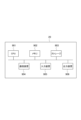
- FIG. 1 is a diagram showing an example of the configuration of a control system.
- FIG. 2 is a diagram showing an example of the configuration of a detector.
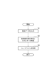
- FIG. 3 is a diagram showing the operation flow of the control device.
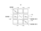
- FIG. 4 is a diagram showing an example of the direction in which radiation comes.
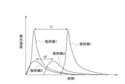
- FIG. 5 is a diagram illustrating an example of the time difference between emission peaks.
- FIG. 6 is a diagram showing an example of the direction in which radiation comes (including an erroneously specified route).
- FIG. 7 is a diagram showing an example of the number of times the radiation route is specified.
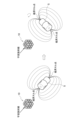
- FIG. 8 is a diagram showing an example of control of the solenoid type magnetic field generator.
- FIG. 9 is a diagram showing an example of the hardware configuration of the control device.
- FIG. 1 is a diagram showing a configuration example of a control system 1 according to the present embodiment.
- the control system 1 includes a detector 10 that detects radiation, and a control device 20 that controls the solenoid magnetic field generator S based on the detection result of the radiation detected by the detector 10.
- the control device 20 can communicate with each of the detector 10 and the solenoid-type magnetic field generator S.
- the control device 20 includes a processing unit 21 that uses the detector 10 to identify the direction and energy of the radiation, and a control unit that controls the solenoid coil of the solenoid-type magnetic field generator S so that the magnetic field null point does not face the direction in which the radiation comes. 22.
- the control device 20 may be configured outside the detector 10 or may be configured inside the detector 10.
- FIG. 2 is a diagram showing an example of the configuration of the detector 10.
- FIG. 2(a) is an external view of the detector 10.
- FIG. 2(b) is a cross-sectional view taken along line AB in FIG. 2(a).
- the detector 10 includes a plurality of rectangular parallelepiped sensors 11 that detect radiation.
- the detector 10 includes a 3 ⁇ 3 ⁇ 3 sensor group in which three sensors 11 are arranged in each of the horizontal direction (x-axis), depth direction (y-axis), and height direction (z-axis).
- the center of the sensor group is hollow, and the number of sensors in the sensor group is 26.
- Each sensor 11 includes a scintillator 101 that emits light due to a nuclear reaction upon incidence of radiation, a photomultiplier tube 102 that amplifies the emitted light of the scintillator 101, and a photomultiplier tube 102 that amplifies the emitted light from the other scintillators 101 in the detector 10.
- a light-shielding thin film 103 that removes the influence is provided.
- each sensor 11 has a function of individually emitting light when radiation is incident thereon and amplifying the emitted light.
- the 3 ⁇ 3 ⁇ 3 sensor group is an example of the detector 10.
- the detector 10 may be configured with a 3 ⁇ 4 ⁇ 5 sensor group, or may be configured with a 5 ⁇ 5 ⁇ 5 sensor group. As the number of sensors increases, the ability to capture radiation improves.
- FIG. 3 is a diagram showing the operation flow of the control device 20.
- Step S1 First, the processing unit 21 inputs light emission data detected by the sensor 11 of the detector 10.
- the processing unit 21 identifies the direction in which the radiation comes from the direction in which the line segment connecting the two sensors 11 that detected the light emission is extended. For example, as shown in FIG. 4, when the sensor 11A and the sensor 11H emit light at a certain timing, the processing unit 21 determines that the extending direction of the straight line passing through the position of the sensor 11A and the position of the sensor 11H is the incoming direction of the radiation 1. do. Similarly, when the sensor 11D and the sensor 11E emit light at different timings, the processing unit 21 sets the direction in which the radiation 2 comes in the direction of extension of the straight line passing through the position of the sensor 11D and the position of the sensor 11E.
- the processing unit 21 identifies the radiation energy based on the time difference between the light emission peaks of the two sensors 11 that detected the light emission. For example, as shown in FIG. 5, the processing unit 21 identifies the radiation 1 based on the time difference t1 between the light emission peak at the sensor 11A and the light emission peak at the sensor 11H. Similarly, the processing unit 21 identifies the radiation 2 based on the time difference t2 between the light emission peak at the sensor 11D and the light emission peak at the sensor 11E. The higher the energy of the radiation, the closer it approaches the speed of light, so the energy can be determined by determining how long it takes for the radiation to reach the known distance between the sensors 11.
- the processing unit 21 further specifies the type of radiation.
- the processing unit 21 discriminates the type of radiation by analyzing the emission characteristics (for example, temporal changes in emission intensity).
- the processing unit 21 specifies a radiation path that connects two of the four sensors 11 emitted by radiation with a straight line, and determines the direction in which the radiation comes from based on the number of times the path is specified.
- the processing unit 21 sets the straight path between the sensor 11A and the sensor 11H as the path of the radiation 1, the straight path between the sensor 11D and the sensor 11E as the path of the radiation 2, and the straight path between the sensor 11A and the sensor 11E as the path of the radiation 3.
- the straight path of the sensor 11D and the sensor 11H is defined as the path of the radiation 4, and the actual direction of the radiation is determined by calculating the number of route identification times (integrated value) of these paths and comparing them with each other.
- the number of times the route has been specified is extremely small, so it is determined that the route has been incorrectly specified.
- the control device 20 specifies the direction and energy of the radiation using the detector 10 using a scintillator, and controls the solenoid-type magnetic field generator S so that the magnetic field null point does not face the direction of the radiation. Since the solenoid coil is controlled, it is possible to provide technology that can more reliably protect equipment and living organisms from radiation coming from various directions.
- the control device 20 of the present embodiment described above includes, for example, as shown in FIG. 9, a CPU 901, a memory 902, a storage 903, a communication device 904, an input device 905, and an output device 906. It can be realized using a general-purpose computer system. Memory 902 and storage 903 are storage devices. In the computer system, each function of the control device 20 is realized by the CPU 901 executing a predetermined program loaded onto the memory 902.
- the control device 20 may be implemented by one computer.
- the control device 20 may be implemented by multiple computers.
- the control device 20 may be a virtual machine implemented in a computer.
- the program for the control device 20 can be stored in a computer-readable recording medium such as an HDD, SSD, USB memory, CD, or DVD.
- the program for the control device 20 can also be distributed via a communication network.
- Control system 10 Detector 11: Sensor 101: Scintillator 102: Photomultiplier tube 103: Light-shielding thin film 20: Control device 21: Processing section 22: Control section 901: CPU 902: Memory 903: Storage 904: Communication device 905: Input device 906: Output device
Landscapes
- Health & Medical Sciences (AREA)
- Engineering & Computer Science (AREA)
- General Health & Medical Sciences (AREA)
- Remote Sensing (AREA)
- Emergency Medicine (AREA)
- Critical Care (AREA)
- Toxicology (AREA)
- Aviation & Aerospace Engineering (AREA)
- Measurement Of Radiation (AREA)
- Physics & Mathematics (AREA)
- Life Sciences & Earth Sciences (AREA)
- General Physics & Mathematics (AREA)
- High Energy & Nuclear Physics (AREA)
- Molecular Biology (AREA)
- Spectroscopy & Molecular Physics (AREA)
Abstract
Description
まず、処理部21は、検出器10のセンサ11で検出された発光データを入力する。
次に、処理部21は、入力した発光データを用いて放射線の飛来方向とエネルギーを特定する。具体的には、処理部21は、発光を検出した2つのセンサ11の位置と当該2つのセンサ11の発光ピークの時間差を基に、検出器10に入射した放射線の飛来方向とエネルギーを特定する。
最後に、制御部22は、処理部21が特定した放射線の飛来方向とエネルギーと種別を基に、ソレノイド型磁界発生装置Sを制御する。例えば、制御部22は、図8に示すように、放射線の飛来方向を基に、その放射線の飛来方向に磁界ヌル点が向かないようにソレノイドコイルによる強磁界バリアの向きを変更する。制御部22は、放射線のエネルギーや種別を基に強磁界バリアの強度を変更する。制御部22は、強磁界バリアの向きや強度を最適化し、強磁界バリアによる効果を最大化する。
10:検出器
11:センサ
101:シンチレータ
102:光電子増倍管
103:遮光性薄膜
20:制御装置
21:処理部
22:制御部
901:CPU
902:メモリ
903:ストレージ
904:通信装置
905:入力装置
906:出力装置
Claims (6)
- シンチレータを用いた検出器により放射線の飛来方向を特定する処理部と、
前記放射線の飛来方向に磁界ヌル点が向かないようにソレノイドコイルを制御する制御部と、
を備える制御装置。 - 前記検出器は、複数のシンチレータを備え、
前記処理部は、
放射線により発光した2つのシンチレータの位置を基に前記放射線の飛来方向を特定する請求項1に記載の制御装置。 - 前記検出器は、複数のシンチレータを備え、
前記処理部は、
放射線により発光した2つのシンチレータの発光ピークの時間差を基に前記放射線のエネルギーを特定する請求項1に記載の制御装置。 - 前記検出器は、複数のシンチレータを備え、
前記処理部は、
放射線により発光した2つのシンチレータを直線で結ぶ放射線の経路を特定し、特定した経路特定回数を基に前記放射線の飛来方向を判定する請求項1に記載の制御装置。 - 前記検出器は、
複数のシンチレータが横方向と奥行き方向と高さ方向に配置され、内部が中空である請求項1乃至4のいずれかに記載の制御装置。 - 制御装置で行う制御方法において、
シンチレータを用いた検出器により放射線の飛来方向を特定するステップと、
前記放射線の飛来方向に磁界ヌル点が向かないようにソレノイドコイルを制御するステップと、
を含む制御方法。
Priority Applications (3)
| Application Number | Priority Date | Filing Date | Title |
|---|---|---|---|
| PCT/JP2022/020050 WO2023218595A1 (ja) | 2022-05-12 | 2022-05-12 | 制御装置、及び、制御方法 |
| JP2024520174A JP7807694B2 (ja) | 2022-05-12 | 2022-05-12 | 制御装置、及び、制御方法 |
| US18/858,815 US20250271583A1 (en) | 2022-05-12 | 2022-05-12 | Control device and control method |
Applications Claiming Priority (1)
| Application Number | Priority Date | Filing Date | Title |
|---|---|---|---|
| PCT/JP2022/020050 WO2023218595A1 (ja) | 2022-05-12 | 2022-05-12 | 制御装置、及び、制御方法 |
Publications (1)
| Publication Number | Publication Date |
|---|---|
| WO2023218595A1 true WO2023218595A1 (ja) | 2023-11-16 |
Family
ID=88730061
Family Applications (1)
| Application Number | Title | Priority Date | Filing Date |
|---|---|---|---|
| PCT/JP2022/020050 Ceased WO2023218595A1 (ja) | 2022-05-12 | 2022-05-12 | 制御装置、及び、制御方法 |
Country Status (3)
| Country | Link |
|---|---|
| US (1) | US20250271583A1 (ja) |
| JP (1) | JP7807694B2 (ja) |
| WO (1) | WO2023218595A1 (ja) |
Citations (2)
| Publication number | Priority date | Publication date | Assignee | Title |
|---|---|---|---|---|
| US20060169489A1 (en) * | 2005-01-28 | 2006-08-03 | Kinstler Gary A | Method and device for magnetic space radiation shield |
| US20110049303A1 (en) * | 2009-03-26 | 2011-03-03 | The Science And Technology Facilities Council | Spacecraft shield |
-
2022
- 2022-05-12 WO PCT/JP2022/020050 patent/WO2023218595A1/ja not_active Ceased
- 2022-05-12 JP JP2024520174A patent/JP7807694B2/ja active Active
- 2022-05-12 US US18/858,815 patent/US20250271583A1/en active Pending
Patent Citations (2)
| Publication number | Priority date | Publication date | Assignee | Title |
|---|---|---|---|---|
| US20060169489A1 (en) * | 2005-01-28 | 2006-08-03 | Kinstler Gary A | Method and device for magnetic space radiation shield |
| US20110049303A1 (en) * | 2009-03-26 | 2011-03-03 | The Science And Technology Facilities Council | Spacecraft shield |
Non-Patent Citations (4)
| Title |
|---|
| GHELMAN MAX, KOPEIKA NATAN, ROTMAN STANLEY, EDVABSKY TAL, VAX ERAN, OSOVIZKY ALON: "Design of 4 π High-Efficiency Directional Radiation Detector Based on Compton Scattering", IEEE TRANSACTIONS ON NUCLEAR SCIENCE, IEEE, USA, vol. 69, no. 4, 1 April 2022 (2022-04-01), USA, pages 832 - 839, XP093108555, ISSN: 0018-9499, DOI: 10.1109/TNS.2022.3159663 * |
| R. R. S. MENDONÇA, C. WANG, C. R. BRAGA, E. ECHER, A. DAL LAGO, J. E. R. COSTA, K. MUNAKATA, H. LI, Z. LIU, J.-P. RAULIN, T. KUWAB: "Analysis of cosmic rays' atmospheric effects and their relationships to cutoff rigidity and zenith angle using Global Muon Detector Network data", ARXIV.ORG, CORNELL UNIVERSITY LIBRARY, 201 OLIN LIBRARY CORNELL UNIVERSITY ITHACA, NY 14853, 14 October 2019 (2019-10-14), 201 Olin Library Cornell University Ithaca, NY 14853 , XP081512823, DOI: 10.1029/2019JA026651 * |
| SPILLANTINI, P. CASOLINO, M. DURANTE, M. MUELLER-MELLIN, R. REITZ, G. ROSSI, L. SHURSHAKOV, V. SORBI, M.: "Shielding from cosmic radiation for interplanetary missions: Active and passive methods", RADIATION MEASUREMENTS., ELSEVIER, AMSTERDAM., NL, vol. 42, no. 1, 28 November 2006 (2006-11-28), NL , pages 14 - 23, XP005782639, ISSN: 1350-4487, DOI: 10.1016/j.radmeas.2006.04.028 * |
| STADNICHUK E., ABRAMOVA T., ZELENYI M., IZVESTNYY A., NOZIK A., PALMIN V., ZIMOVETS I.: "Prototype of a segmented scintillator detector for particle flux measurements on spacecraft", JOURNAL OF INSTRUMENTATION, INSTITUTE OF PHYSICS PUBLISHING, BRISTOL, GB, vol. 15, no. 09, 14 September 2020 (2020-09-14), GB , pages T09006, XP093108551, ISSN: 1748-0221, DOI: 10.1088/1748-0221/15/09/T09006 * |
Also Published As
| Publication number | Publication date |
|---|---|
| JP7807694B2 (ja) | 2026-01-28 |
| US20250271583A1 (en) | 2025-08-28 |
| JPWO2023218595A1 (ja) | 2023-11-16 |
Similar Documents
| Publication | Publication Date | Title |
|---|---|---|
| KM3NeT Collaboration km3net-pc@ km3net. de et al. | Astronomy potential of KM3NeT/ARCA | |
| US9535177B2 (en) | Gamma-ray spectrometry | |
| CN102288982B (zh) | 基于闪烁体的二维位置探测系统 | |
| US9759823B1 (en) | Directional radiation detectors | |
| Abdurashitov et al. | Setup of Compton polarimeters for measuring entangled annihilation photons | |
| US7142625B2 (en) | Nuclear material detection apparatus and method | |
| CN105534542B (zh) | 一种pet系统的实现方法和装置 | |
| CN113376680B (zh) | 用于半导体探测器的读出电路和方法以及半导体探测系统 | |
| US7274020B1 (en) | Gamma vector camera | |
| JP7807694B2 (ja) | 制御装置、及び、制御方法 | |
| US20110068274A1 (en) | Using uv light source for self testing gas filled gamma and neutron detectors | |
| US10527561B2 (en) | Device and method for analysis of material by neutron interrogation | |
| CN119466758A (zh) | 一种随钻中子孔隙度密度测量装置及时钟标签方法 | |
| KR101094159B1 (ko) | 전 방향 감마 방사선 검출기를 통한 핵폭발 발생 및 방향 고속탐지 기능을 가진 핵폭 경보기 및 그 구현 방법 | |
| KR101686306B1 (ko) | 방사선 계수 방식 센서 신호 처리단의 신호 중첩으로 인한 손실 정보를 막고 에너지의 왜곡을 없애는 방법과 구조 | |
| JP2015010837A (ja) | 放射線計測装置 | |
| CN110333179B (zh) | 一种深空带电粒子探测器触发方法 | |
| EP3881103A1 (en) | Occlusion-based directionality and localization of radiation sources with modular detection systems and methods | |
| KR102621725B1 (ko) | 데이터 출력 장치 | |
| CN119758427B (zh) | 表面缪子束的束流强度测量系统、方法及存储介质 | |
| KR102844639B1 (ko) | 이온빔 측정장치 및 이를 포함하는 이온빔 측정 시스템 | |
| RU85679U1 (ru) | Широкоапертурный сцинтилляционный детектор для определения параметров нейтронного потока в нейтронном генераторе | |
| US20190285760A1 (en) | Methods and apparatus for directional detection of antineutrinos | |
| Vanier et al. | Thermal neutron imaging in an active interrogation environment | |
| US20240176034A1 (en) | Pulse shape discrimination techniques for dual-mode scintillator detectors |
Legal Events
| Date | Code | Title | Description |
|---|---|---|---|
| 121 | Ep: the epo has been informed by wipo that ep was designated in this application |
Ref document number: 22941675 Country of ref document: EP Kind code of ref document: A1 |
|
| WWE | Wipo information: entry into national phase |
Ref document number: 2024520174 Country of ref document: JP |
|
| WWE | Wipo information: entry into national phase |
Ref document number: 18858815 Country of ref document: US |
|
| NENP | Non-entry into the national phase |
Ref country code: DE |
|
| 122 | Ep: pct application non-entry in european phase |
Ref document number: 22941675 Country of ref document: EP Kind code of ref document: A1 |
|
| WWP | Wipo information: published in national office |
Ref document number: 18858815 Country of ref document: US |