WO2023218556A1 - 無線通信方法及び無線通信システム - Google Patents
無線通信方法及び無線通信システム Download PDFInfo
- Publication number
- WO2023218556A1 WO2023218556A1 PCT/JP2022/019929 JP2022019929W WO2023218556A1 WO 2023218556 A1 WO2023218556 A1 WO 2023218556A1 JP 2022019929 W JP2022019929 W JP 2022019929W WO 2023218556 A1 WO2023218556 A1 WO 2023218556A1
- Authority
- WO
- WIPO (PCT)
- Prior art keywords
- wireless communication
- rainfall
- communication system
- relay station
- relay
- Prior art date
- Legal status (The legal status is an assumption and is not a legal conclusion. Google has not performed a legal analysis and makes no representation as to the accuracy of the status listed.)
- Ceased
Links
Images









Classifications
-
- H—ELECTRICITY
- H04—ELECTRIC COMMUNICATION TECHNIQUE
- H04W—WIRELESS COMMUNICATION NETWORKS
- H04W40/00—Communication routing or communication path finding
- H04W40/02—Communication route or path selection, e.g. power-based or shortest path routing
- H04W40/12—Communication route or path selection, e.g. power-based or shortest path routing based on transmission quality or channel quality
-
- H—ELECTRICITY
- H04—ELECTRIC COMMUNICATION TECHNIQUE
- H04B—TRANSMISSION
- H04B7/00—Radio transmission systems, i.e. using radiation field
- H04B7/14—Relay systems
- H04B7/15—Active relay systems
- H04B7/185—Space-based or airborne stations; Stations for satellite systems
- H04B7/18502—Airborne stations
- H04B7/18506—Communications with or from aircraft, i.e. aeronautical mobile service
-
- H—ELECTRICITY
- H04—ELECTRIC COMMUNICATION TECHNIQUE
- H04B—TRANSMISSION
- H04B7/00—Radio transmission systems, i.e. using radiation field
- H04B7/14—Relay systems
- H04B7/15—Active relay systems
- H04B7/185—Space-based or airborne stations; Stations for satellite systems
- H04B7/1851—Systems using a satellite or space-based relay
- H04B7/18513—Transmission in a satellite or space-based system
-
- H—ELECTRICITY
- H04—ELECTRIC COMMUNICATION TECHNIQUE
- H04W—WIRELESS COMMUNICATION NETWORKS
- H04W16/00—Network planning, e.g. coverage or traffic planning tools; Network deployment, e.g. resource partitioning or cells structures
- H04W16/24—Cell structures
- H04W16/26—Cell enhancers or enhancement, e.g. for tunnels, building shadow
-
- H—ELECTRICITY
- H04—ELECTRIC COMMUNICATION TECHNIQUE
- H04W—WIRELESS COMMUNICATION NETWORKS
- H04W24/00—Supervisory, monitoring or testing arrangements
- H04W24/04—Arrangements for maintaining operational condition
-
- H—ELECTRICITY
- H04—ELECTRIC COMMUNICATION TECHNIQUE
- H04W—WIRELESS COMMUNICATION NETWORKS
- H04W84/00—Network topologies
- H04W84/02—Hierarchically pre-organised networks, e.g. paging networks, cellular networks, WLAN [Wireless Local Area Network] or WLL [Wireless Local Loop]
- H04W84/04—Large scale networks; Deep hierarchical networks
- H04W84/06—Airborne or Satellite Networks
Definitions
- the present invention relates to a wireless communication method and a wireless communication system.
- Super coverage refers to expanding the service area to places where it is expensive to install existing base stations or where it is difficult to install base stations, such as in the mountains, at sea, and in the air. There is also a need to strengthen national resilience against natural disasters, and it is hoped that a communication system that can withstand ground disasters will emerge.
- GEO geostationary orbit satellites
- MEO medium earth orbit satellites
- LEO low earth orbit satellites
- HAPS high altitude pseudosatellites
- NTN Non-terrestrial networks using high altitude platform stations, unmanned aerial vehicles (UAVs), and drones have been in the spotlight (for example, see Non-Patent Document 1).
- the above-mentioned satellites, HAPS, etc. connect communication links to each other to form a network, and are further connected to a terrestrial mobile network via a terrestrial base station. Satellites and HAPS are equipped with relay communication functions.
- the communication line in HAPS consists of a feeder link (FL) between HAPS and a terrestrial gateway station (ground station) on the terrestrial communication network side, and a service link (SL) between a communication relay device and a terminal.
- FL feeder link
- ground station terrestrial gateway station
- SL service link
- HAPS is located at an altitude of approximately 20 km, and the ground area (cell) radius is approximately 50 km.
- the HAPS service link is expected to use a frequency of 2 GHz, but the use of millimeter waves in a higher frequency band (eg, 38 GHz band) is being considered for the feeder link.
- the traffic packets transmitted by the terminal are forwarded to the HAPS connected to the ground station by the routing function, and sent to the Internet network. Similar processing is performed on packets sent from the Internet network to other terminals by the routing function.
- NTN uses radio waves in a high frequency band, and it is assumed that the quality of wireless communication will deteriorate due to the influence of rain. For example, if there is an influence of rain, there is a risk that the service of NTN's FL (feeder link), which uses a high frequency band, may be cut off due to the rain.
- NTN's FL feeder link
- Non-Patent Document 2 a method of switching feeder links within an area (cell) covered by one HAPS using rainfall prediction is being considered (e.g., Non-Patent Document 2). reference).
- FIGURE 1 shows the characteristics for each hourly rainfall intensity (mm/h) (for example, non-patent literature (See 3).
- FIGURE 1 shows the concept of rain propagation path length and elevation angle (for example, see Non-Patent Document 4).
- the present invention has been made in view of the above-mentioned problems, and is aimed at preventing deterioration of communication quality even when the entire area covered by one relay station moving in the sky in the NTN is affected by rain.
- the purpose of the present invention is to provide a wireless communication method and a wireless communication system that enable the following.
- a wireless communication method is a wireless communication method involving an NTN, in which a plurality of relay stations moving above the NTN and the relay An extraction step of extracting rainfall data at predetermined intervals between each cell formed by the station and a plurality of ground stations placed on the ground; a prediction step of predicting communication deterioration of each feeder link due to rainfall, and whether or not the feeder links of each of the plurality of relay stations satisfy a predetermined communication quality based on each of the predicted communication deteriorations of the feeder links. and a control step of controlling the feeder link so that it satisfies a predetermined communication quality when it is determined that the feeder link of the relay station to which the service link is connected does not satisfy a predetermined communication quality. It is characterized by including.
- a wireless communication system is capable of connecting a plurality of relay stations moving above the NTN based on rainfall prediction for each predetermined area based on observation data of a weather radar.
- an extraction unit that extracts rainfall data between each cell formed by the relay station and a plurality of ground stations placed on the ground at predetermined time intervals; a prediction unit that predicts the communication deterioration of the feeder links due to rain at the plurality of relay stations; and a prediction unit that predicts the communication deterioration of the feeder links due to rain at the plurality of relay stations, and the feeder link of each of the plurality of relay stations based on the communication deterioration of the feeder links predicted by the prediction unit.
- a determination unit that determines whether or not the relay station satisfies a predetermined communication quality;
- the present invention is characterized by comprising a control unit that controls the feeder link so that it satisfies predetermined communication quality.
- the present invention it is possible to prevent communication quality from deteriorating even when the entire area covered by one relay station moving in the sky in the NTN is affected by rain.
- FIG. 2 is a diagram illustrating a wireless communication system in which cells C2 to C9 are arranged around cell C1.
- FIG. 4 is a diagram illustrating a case where rain clouds cover a plurality of cells in the wireless communication system shown in FIG. 3.
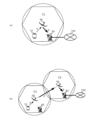
- FIG. 2 is a diagram illustrating the relationship between a ground station, a relay station, and a rain cloud in a wireless communication system according to an embodiment.
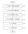
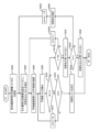
- 2 is a flowchart illustrating an example of overall processing of a wireless communication system. It is a flowchart which shows the details of the process which acquires FL frequency, 1-hour rainfall intensity, and attenuation amount.
- 12 is a flowchart showing details of processing for obtaining the latitude and longitude of the ground station of each cell. It is a flowchart which shows the details of the process which extracts the rainfall intensity data of each cell. It is a flowchart which shows the details of the process which extracts the predicted value of the rainfall intensity data of each cell. 12 is a flowchart showing details of processing for considering cell switching.
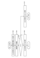
- FIG. 12 is a flowchart showing details of processing for considering a cell switching destination.
- FIG. 3 is a diagram showing the relationship between rainfall intensity (mm/h) and attenuation (dB).
- FIG. 3 is a diagram showing the relationship between rainfall intensity (mm/h) and attenuation amount (dB) for each frequency. It is a figure which shows the example of the predicted value of the rainfall intensity of the high-resolution precipitation nowcast of cell C1 point. It is a figure which shows the example of the predicted value of the rainfall intensity of the high-resolution precipitation nowcast of cell C2 point. It is a figure which shows the example of the predicted value of the rainfall intensity of the high-resolution precipitation nowcast of cell C3 point.
- FIG. 2 is a diagram schematically showing how rainfall intensity is converted into rainfall attenuation amount.
- FIG. 1 is a diagram illustrating a configuration example of a wireless communication system according to an embodiment including an NTN.
- FIG. 1A is a diagram showing an example of the configuration of a wireless communication system including a cell formed by one relay station moving in the sky.
- FIG. 1(b) is a diagram illustrating a configuration example of a wireless communication system including a cell formed by two relay stations moving in the sky. Note that the number of cells in the wireless communication system according to one embodiment is not limited.
- a terminal 10 and a ground station 20 perform wireless communication via a relay station 30 that moves in the sky, such as a HAPS.
- Relay station 30 forms an area (cell C1) that covers wireless communication.
- the relay station 30 may be a low orbit satellite (LEO) or the like.
- ground station 20 is placed on the ground and is connected to other base stations, other terminals 10, a control station, etc. (not shown) via the network 100.
- the terminal 10 transmits a signal to the relay station 30 using, for example, a service link of S-band radio waves.
- the relay station 30 transmits the signal to the ground station 20 using, for example, a Q/V band radio wave feeder link.
- the wireless communication system equipped with NTN transmits radio waves in the Q/V band, for example, from the relay station 30 forming the cell C1 to the relay station 30 forming the adjacent cell C2. Connections that transmit signals are made possible using .
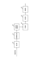
- FIG. 2 is a functional block diagram illustrating functions included in a wireless communication system according to an embodiment. Note that each function shown in FIG. 2 may be provided in whole or in part by any of the terminal 10, the ground station 20, the relay station 30, and a control station (not shown).
- the wireless communication system includes an extraction section 40, an interval calculation section 41, a loss amount calculation section 42, a prediction section 43, a determination section 44, and a control section 45.
- the extraction unit 40 calculates rainfall between the plurality of relay stations 30 and the plurality of ground stations 20 for each cell formed by the relay stations 30, based on rainfall prediction for each predetermined area based on observation data of a weather radar. Data is extracted at predetermined time intervals and output to the section calculation unit 41. For example, the extraction unit 40 obtains rainfall predictions such as high-resolution precipitation nowcasts and extracts rainfall data at predetermined intervals.
- the high-resolution precipitation nowcast provides rainfall mesh data predicted and analyzed by a supercomputer based on international rules (GRIB format).
- GPIB format international rules
- high-resolution precipitation nowcasts provide detailed analysis of rain clouds and predict their movement, development, weakening, and new occurrences.
- the analysis time is every 5 minutes
- the grid interval is 250 m
- the prediction time/time resolution is every 1 hour/5 minutes
- the prediction grid interval is 250 m up to 30 minutes
- the section calculation section 41 calculates each rainfall section between the relay station 30 and the ground station 20 based on the rainfall data extracted by the extraction section 40, and outputs it to the loss amount calculation section 42.
- the loss amount calculation section 42 calculates the amount of radio wave propagation loss caused by the rainy section calculated by the section calculation section 41, and outputs it to the prediction section 43.
- the prediction unit 43 predicts the communication deterioration of the feeder links caused by rain at the plurality of relay stations 30 based on each of the radio wave propagation losses calculated by the loss calculation unit 42, and outputs the prediction to the determination unit 44. do.
- the determining unit 44 determines whether the feeder links of each of the plurality of relay stations 30 satisfy a predetermined communication quality based on the communication deterioration of the feeder links predicted by the predicting unit 43, and transmits the determination result to the control unit. 45.
- the control unit 45 controls the feeder link so that the feeder link satisfies the predetermined communication quality. conduct.
- control unit 45 may control the feeder link of the relay station 30 to which the service link is connected. Control is performed to switch the propagation path so that one of the other relay stations 30, which the determination unit 44 has determined to satisfy a predetermined communication quality, relays to one of the ground stations 20.
- control unit 45 increases the transmission power of the relay station 30. control, or control may be performed to change the modulation method or coding rate of the relay station 30.
- the wireless communication system extracts rainfall intensity data in the NTN direction from the NTN ground station using the rainfall data of the high-resolution precipitation nowcast, and extracts rainfall intensity data in the NTN direction from the NTN ground station, and extracts rainfall intensity data in the NTN direction based on the current value and predicted value of the rainfall data. , predict communication degradation due to rain, compare communication quality within a cell with data from other cells, and consider and decide to switch the propagation path to a cell that is not affected by rain.
- FIG. 3 is a diagram illustrating a wireless communication system in which cells C2 to C9 are arranged around cell C1.
- a plurality of relay stations 30 forming cells C1 to C9 are each connectable to other relay stations 30 forming adjacent cells. Note that the configuration of each cell is the same as that shown in FIG.
- FIG. 4 is a diagram illustrating a case where rain clouds cover a plurality of cells in the wireless communication system shown in FIG. 3. In a cell covered with rain clouds, wireless communication may be affected as will be described later.
- FIG. 5 is a diagram illustrating the relationship between the ground station 20, the relay station 30, and rain clouds in the wireless communication system according to one embodiment.
- the altitude at which the raindrops are located and the assumed horizontal distance of the rain cloud radar are shown.
- the wireless communication system uses high-resolution precipitation nowcast data obtained from rain cloud radar and can select a cell to connect to based on rainfall prediction. Note that high-resolution precipitation nowcasts contain only data in the horizontal direction, so only the horizontal direction will be considered.
- a relay station 30 such as HAPS stays at an altitude of 20 km and has an area with a radius of about 50 km, so the elevation angle when viewing the relay station 30 from the ground station 20 is 90 degrees at the center of the area and 90 degrees at the edge of the area. It will be about 21.8 degrees.
- the horizontal distance affected by raindrops is 4 km, the same as the altitude, as shown in equations (1) and (2) below.
- the high-resolution precipitation nowcast uses 250m mesh rainfall data, so 16 meshes corresponds to 4km.
- FIG. 6 is a diagram showing the relationship between the altitude to be considered, the area, and the number of meshes.
- the altitude to be considered 2 km
- 2 km/tan (45°) 2 km
- the altitude to be considered 4 km
- 4 km/tan (45°) 4 km
- the altitude to be considered 7 km
- 7 km/tan (45°) 7 km, and there are 28 250 m meshes (c).
- the high-resolution precipitation nowcast data is a GRIB2 format file, but the necessary information can be extracted as a CSV file.
- CSV file based on the location (latitude and longitude) of the ground station 20 of the switching source cell C1 and the switching destination cells C2 to C4, 60 minutes after the current value of the target 16 meshes in the direction of the relay station 30 of each cell. (See Figures 16 to 19).
- the wireless communication system predicts rain attenuation based on rainfall intensity data, selects ground stations 20 of cells that are not affected by rain, and maintains communication, thereby achieving improved availability ( Figure 7 (See ⁇ 13).
- FIG. 7 is a flowchart showing an example of the overall processing of the wireless communication system.
- the wireless communication system acquires (A) the FL frequency, 1h rainfall intensity and attenuation amount (S100), and (B) acquires the latitude and longitude of the ground station of each cell as initial parameter settings. (S200).
- the wireless communication system extracts the rainfall intensity data of each cell (S300), and (D) extracts the predicted value of the rainfall intensity data of each cell (S400).
- the wireless communication system (E) considers cell switching (S500), and (F) considers the cell switching destination (S600).
- FIG. 8 is a flowchart showing details of the process for acquiring (A) FL frequency, 1-h rainfall intensity, and attenuation amount.
- the wireless communication system calculates the rainfall intensity for each hour of the set frequency (f) based on the frequency (GHz) characteristics of rainfall attenuation (dB/km) of CCIR Rep. 721-3 shown in Figure 14.
- Rain attenuation (dB/km) of (mm/h) is extracted (S104).
- the signal in the 38 GHz band, if it rains at 5 mm/h for 1 km, the signal will be attenuated by 1.5 dB. For example, in the 38 GHz band, if rain continues for 1 km at a rate of 25 mm/h, the signal will be attenuated by 6 dB.
- FIG. 9 is a flowchart showing the details of (B) the process of obtaining the latitude and longitude of the ground station of each cell.
- the wireless communication system sets the latitude and longitude of the ground station 20 of each cell of the relay station 30 (S204).
- the wireless communication system sets cell C1: (22.1625,121.75625), cell C2: (22.15833,122.8813), cell C3: (22.15625,124.0063), and cell C4: (22.15417,125.1313).
- the process of acquiring the latitude and longitude of the cell's ground station ends.
- FIG. 10 is a flowchart showing the details of (C) the process of extracting rainfall intensity data for each cell.
- the wireless communication system sets the latitude and longitude of the ground station 20 of the target cell as (22.1625, 121.75625) for the C1 cell, for example.
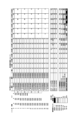
- FIG. 16 shows an example of predicted values of rainfall intensity from high-resolution precipitation nowcast (5 minutes) at cell C1 point. For example, attenuation of 5 dB/km in the 38 GHz band occurs when the rainfall intensity is approximately 20 mm/h. Therefore, considering 1 km, the time will come in 50 minutes, and the wireless communication system determines that it is necessary to switch to another relay station 30 by then.
- the time will come in 40 minutes
- the time will come in 35 minutes
- you think up to 4km in the above example, the time will come in 30 minutes.
- the wireless communication system extracts the current value of the rainfall intensity (mm/h) for a horizontal distance of X km (S312), and extracts the predicted value of the rainfall intensity for 60 minutes every 5 minutes. Extract (S314).
- the wireless communication system calculates the average of the current value and predicted value of the rainfall intensity (250 m mesh x 4) for each 1 km in the horizontal direction.
- the wireless communication system calculates the rainfall intensity for each 1 km and calculates the cumulative value of the rainfall intensity.
- 0 to 1 km is shown in row (1), up to 2 km is shown in (2), and the following are shown in rows (3) and (4).
- the wireless communication system calculates the cumulative value of rainfall intensity over a horizontal distance of X km. In FIG. 16, it is shown as "(1)+(2)+(3)+(4) equivalent to 4 km".
- the wireless communication system calculates the rainfall intensity in the rainy section.
- the actual rain section on the propagation path is (sin(El)) -1 times the horizontal distance Xkm using the elevation angle El.
- the rain section is multiplied by ⁇ 2 (see FIG. 16).
- FIG. 11 is a flowchart showing the details of (D) the process of extracting predicted values of rainfall intensity data for each cell.
- the wireless communication system determines whether the prediction target time (t) is equal to or greater than the final prediction target time (60 minutes), and if it is equal to or greater than the final prediction target time (S404: Yes). (D) ends the process of extracting the predicted rainfall intensity data value for each cell, and if it is not longer than the final prediction target time (S404: No), the process proceeds to S406.
- the prediction target time will be explained as 30 minutes.
- the wireless communication system extracts the rainfall intensity of each cell after t minutes.
- the wireless communication system extracts the rainfall intensity and actual rainfall section for each 250m mesh, for each 1km, and for the horizontal distance of Xkm.
- the wireless communication system calculates the predicted rainfall intensity (R) for each mesh after 30 minutes, 45 minutes, and 60 minutes for each cell by calculating the predicted value for each mesh during the t minutes of the actual rainfall period. Extract as post data. Furthermore, the wireless communication system simultaneously extracts predicted values of rainfall intensity (1) to (4). For example, as shown in FIG. 20, the wireless communication system extracts the predicted value of rainfall intensity of "4 km (1) + (2) + (3) + (4)" and the actual rain area.
- FIG. 21 for example, only predicted values of rainfall intensity in "actual rainfall sections" 30 minutes, 45 minutes, and 60 minutes after each cell are extracted.
- the wireless communication system extracts the amount of attenuation (dt) using the rainfall intensity (R) and FIG. 15. For example, the wireless communication system calculates the amount of rainfall attenuation in the 38 GHz band using the predicted rainfall intensity of "4 km (1) + (2) + (3) + (4)" for each cell and Figure 15. is extracted, and the result shown in FIG. 21 is obtained.
- FIG. 12 is a flowchart showing details of (E) processing for considering cell switching.
- the wireless communication system extracts the amount of attenuation (dt) of the actual rainfall section after the prediction target time (t minutes) of cell C1 from FIG. 21, and confirms the amount of attenuation.
- the wireless communication system determines whether the attenuation amount (dt) of the actual rainfall section after the prediction target time (t minutes) of cell C1 is larger than the threshold value (d), and determines whether dt>d If so (S506: Yes), the process advances to S508, and if dt>d does not hold (S506: No), the process advances to S510.
- the wireless communication system determines that the cell should be switched, and moves to (F) the process of considering the cell switch destination.
- the wireless communication system determines that cell switching will not be performed because the attenuation after t minutes exceeds the cell switching threshold (d), and performs (E) processing to consider cell switching. finish.
- FIG. 13 is a flowchart showing the details of (F) the process of considering the cell switching destination.
- the wireless communication system uses FIG. 21 to extract the predicted value dt of the Ci cell after t minutes (S608). At this time, the predicted value of cell C2 after 30 minutes is 4 dB.
- the wireless communication system determines whether the predicted value dt is larger than the threshold value d, and if it is larger (S610: Yes), the process proceeds to S618, and if it is not larger (S610: No), the wireless communication system proceeds to the process of S618.
- the process advances to step S612.
- d 5 dB
- the wireless communication system determines whether the predicted confirmation time t is greater than or equal to the safety confirmation time tt, and if it is greater than or equal to the safety confirmation time tt (S612: Yes), the wireless communication system proceeds to the process of S616, If it is not longer than the safety confirmation time tt (S612: No), the process advances to S614.
- the wireless communication system determines the switching destination to be the cell Cii.
- the wireless communication system determines that no switching destination that does not exceed the threshold d is found until after the safety confirmation time tt, and proceeds to the process of S624.
- the wireless communication system changes the safety confirmation time tt (15 minutes earlier) and considers a switching destination that does not exceed the threshold value d.
- the wireless communication system determines that the switching destination cell is not found, and ends the (F) switching destination cell consideration process.
- the wireless communication system is expected to experience attenuation of 5 dB or more after 30 minutes at the cell C1 location, so switching to another location is considered.
- the wireless communication system switches to point C4, which is less affected by rain (up to about 1.5 dB), after 30 minutes, 45 minutes, and 60 minutes.
- the feeder link of the relay station to which the service link is connected when it is determined that the feeder link of the relay station to which the service link is connected does not satisfy the predetermined communication quality, the feeder link satisfies the predetermined communication quality. Since such control is performed, deterioration in communication quality can be prevented even if the entire area covered by one relay station moving in the sky in the NTN is affected by rain.
- the wireless communication system uses transmitter power control (TCP) to amplify transmission power according to the amount of loss by using the estimation result of the amount of propagation loss such as rain attenuation. ) and AMC that adjusts the required CNIR (Carrier to Noise and Interference Ratio) by adaptively controlling the modulation and coding scheme (MCS) according to the loss. It also has an adaptive modulation and channel coding function.
- TCP transmitter power control
- AMC Carrier to Noise and Interference Ratio
- MCS modulation and coding scheme
- each function shown in FIG. 2 possessed by at least one of the terminal 10, the ground station 20, the relay station 30, and a control station may be partially or completely implemented using a PLD (Programmable Logic Device) or an FPGA (Field Programmable Device). Gate Array) or the like, or may be configured as a program executed by a processor such as a CPU.
- PLD Processable Logic Device
- FPGA Field Programmable Device
- Gate Array Gate Array
- the wireless communication system according to the present invention can be realized using a computer and a program, and the program can be recorded on a storage medium or provided through a network.
Landscapes
- Engineering & Computer Science (AREA)
- Computer Networks & Wireless Communication (AREA)
- Signal Processing (AREA)
- Physics & Mathematics (AREA)
- Astronomy & Astrophysics (AREA)
- Aviation & Aerospace Engineering (AREA)
- General Physics & Mathematics (AREA)
- Mobile Radio Communication Systems (AREA)
- Radio Relay Systems (AREA)
Abstract
Description


Claims (8)
- NTNをともなう無線通信方法において、
気象レーダーの観測データに基づく所定領域ごとの降雨予測から、NTNの上空で移動する複数の中継局と、前記中継局が形成するセルそれぞれに対して地上に配置された複数の地上局との間それぞれの降雨データを所定の時間ごとに抽出する抽出工程と、
抽出した降雨データに基づいて、複数の前記中継局の降雨に起因するフィーダリンクの通信劣化をそれぞれ予測する予測工程と、
予測したフィーダリンクの通信劣化それぞれに基づいて、複数の前記中継局それぞれのフィーダリンクが所定の通信品質を満たしているか否かを判定する判定工程と、
サービスリンクが接続された前記中継局のフィーダリンクが所定の通信品質を満たしていないと判定した場合に、当該フィーダリンクが所定の通信品質を満たすように制御する制御工程と
を含むことを特徴とする無線通信方法。 - 前記制御工程では、
サービスリンクが接続された前記中継局のフィーダリンクが所定の通信品質を満たしていないと判定した場合に、当該中継局のフィーダリンクを、フィーダリンクが所定の通信品質を満たしていると判定した他の前記中継局のいずれかが前記地上局のいずれかに中継するように伝搬路を切替える制御を行うこと
を特徴とする請求項1に記載の無線通信方法。 - 前記制御工程では、
サービスリンクが接続された前記中継局のフィーダリンクが所定の通信品質を満たしていないと判定した場合に、当該中継局の送信電力を増加させるように制御、又は、当該中継局の変調方式若しくは符号化率を変化させるように制御を行うこと
を特徴とする請求項1に記載の無線通信方法。 - 抽出した降雨データに基づいて、前記中継局と前記地上局との間それぞれの降雨区間を算出する区間算出工程と、
算出した降雨区間により生じる電波の伝搬損失量をそれぞれ算出する損失量算出工程と
を含み
前記予測工程では、
算出した電波の伝搬損失量それぞれに基づいて、複数の前記中継局の降雨に起因するフィーダリンクの通信劣化をそれぞれ予測すること
を特徴とする請求項1~3のいずれか1項に記載の無線通信方法。 - NTNを備えた無線通信システムにおいて、
気象レーダーの観測データに基づく所定領域ごとの降雨予測から、NTNの上空で移動する複数の中継局と、前記中継局が形成するセルそれぞれに対して地上に配置された複数の地上局との間それぞれの降雨データを所定の時間ごとに抽出する抽出部と、
前記抽出部が抽出した降雨データに基づいて、複数の前記中継局の降雨に起因するフィーダリンクの通信劣化をそれぞれ予測する予測部と、
前記予測部が予測したフィーダリンクの通信劣化それぞれに基づいて、複数の前記中継局それぞれのフィーダリンクが所定の通信品質を満たしているか否かを判定する判定部と、
サービスリンクが接続された前記中継局のフィーダリンクが所定の通信品質を満たしていないと前記判定部が判定した場合に、当該フィーダリンクが所定の通信品質を満たすように制御する制御部と
を有することを特徴とする無線通信システム。 - 前記制御部は、
サービスリンクが接続された前記中継局のフィーダリンクが所定の通信品質を満たしていないと前記判定部が判定した場合に、当該中継局のフィーダリンクを、フィーダリンクが所定の通信品質を満たしていると前記判定部が判定した他の前記中継局のいずれかが前記地上局のいずれかに中継するように伝搬路を切替える制御を行うこと
を特徴とする請求項5に記載の無線通信システム。 - 前記制御部は、
サービスリンクが接続された前記中継局のフィーダリンクが所定の通信品質を満たしていないと前記判定部が判定した場合に、当該中継局の送信電力を増加させるように制御、又は、当該中継局の変調方式若しくは符号化率を変化させるように制御を行うこと
を特徴とする請求項5に記載の無線通信システム。 - 前記抽出部が抽出した降雨データに基づいて、前記中継局と前記地上局との間それぞれの降雨区間を算出する区間算出部と、
前記区間算出部が算出した降雨区間により生じる電波の伝搬損失量をそれぞれ算出する損失量算出部と
を有し、
前記予測部は、
前記損失量算出部が算出した電波の伝搬損失量それぞれに基づいて、複数の前記中継局の降雨に起因するフィーダリンクの通信劣化をそれぞれ予測すること
を特徴とする請求項5~7のいずれか1項に記載の無線通信システム。
Priority Applications (3)
| Application Number | Priority Date | Filing Date | Title |
|---|---|---|---|
| US18/860,701 US20250293762A1 (en) | 2022-05-11 | 2022-05-11 | Wireless communication method and wireless communication system |
| JP2024520141A JP7816504B2 (ja) | 2022-05-11 | 2022-05-11 | 無線通信方法及び無線通信システム |
| PCT/JP2022/019929 WO2023218556A1 (ja) | 2022-05-11 | 2022-05-11 | 無線通信方法及び無線通信システム |
Applications Claiming Priority (1)
| Application Number | Priority Date | Filing Date | Title |
|---|---|---|---|
| PCT/JP2022/019929 WO2023218556A1 (ja) | 2022-05-11 | 2022-05-11 | 無線通信方法及び無線通信システム |
Publications (1)
| Publication Number | Publication Date |
|---|---|
| WO2023218556A1 true WO2023218556A1 (ja) | 2023-11-16 |
Family
ID=88729968
Family Applications (1)
| Application Number | Title | Priority Date | Filing Date |
|---|---|---|---|
| PCT/JP2022/019929 Ceased WO2023218556A1 (ja) | 2022-05-11 | 2022-05-11 | 無線通信方法及び無線通信システム |
Country Status (3)
| Country | Link |
|---|---|
| US (1) | US20250293762A1 (ja) |
| JP (1) | JP7816504B2 (ja) |
| WO (1) | WO2023218556A1 (ja) |
Cited By (1)
| Publication number | Priority date | Publication date | Assignee | Title |
|---|---|---|---|---|
| WO2025177513A1 (ja) * | 2024-02-22 | 2025-08-28 | Ntt株式会社 | 無線通信システム、リンク制御装置、リンク制御方法、及びリンク制御プログラム |
Citations (4)
| Publication number | Priority date | Publication date | Assignee | Title |
|---|---|---|---|---|
| JPH10190550A (ja) * | 1996-10-21 | 1998-07-21 | Globalstar Lp | 多重衛星フェード減衰制御システム |
| JP2008532361A (ja) * | 2005-02-22 | 2008-08-14 | エイティーシー・テクノロジーズ,リミテッド・ライアビリティ・カンパニー | 間接的なフィーダリンク経路を形成するために衛星間リンクを用いる衛星 |
| JP2021019335A (ja) * | 2019-07-23 | 2021-02-15 | Hapsモバイル株式会社 | Haps通信システムにおける動的サイトダイバーシチ |
| JP7019091B1 (ja) * | 2021-10-20 | 2022-02-14 | ソフトバンク株式会社 | 制御装置、プログラム、システム、及び制御方法 |
-
2022
- 2022-05-11 US US18/860,701 patent/US20250293762A1/en active Pending
- 2022-05-11 WO PCT/JP2022/019929 patent/WO2023218556A1/ja not_active Ceased
- 2022-05-11 JP JP2024520141A patent/JP7816504B2/ja active Active
Patent Citations (4)
| Publication number | Priority date | Publication date | Assignee | Title |
|---|---|---|---|---|
| JPH10190550A (ja) * | 1996-10-21 | 1998-07-21 | Globalstar Lp | 多重衛星フェード減衰制御システム |
| JP2008532361A (ja) * | 2005-02-22 | 2008-08-14 | エイティーシー・テクノロジーズ,リミテッド・ライアビリティ・カンパニー | 間接的なフィーダリンク経路を形成するために衛星間リンクを用いる衛星 |
| JP2021019335A (ja) * | 2019-07-23 | 2021-02-15 | Hapsモバイル株式会社 | Haps通信システムにおける動的サイトダイバーシチ |
| JP7019091B1 (ja) * | 2021-10-20 | 2022-02-14 | ソフトバンク株式会社 | 制御装置、プログラム、システム、及び制御方法 |
Non-Patent Citations (1)
| Title |
|---|
| HIROMU KITANOZOO, JUN SUZUKI, YOSHIHISA KISHIYAMA, YUKI HOKAZONO, TAKAYUKI SOTOYAMA, MIKIHIRO OUCHI, RYU MIURA, HIROYUKI TSUJI: "Development of HAPS Backhaul System using mmWave Frequency -- HAPS as a NTN System for 5G and Beyond --", IEICE TECHNICAL REPORT, IEICE, JP, vol. 121, no. 153 (RCS2021-105), 19 August 2021 (2021-08-19), JP , pages 14 - 19, XP009550498, ISSN: 2432-6380 * |
Cited By (1)
| Publication number | Priority date | Publication date | Assignee | Title |
|---|---|---|---|---|
| WO2025177513A1 (ja) * | 2024-02-22 | 2025-08-28 | Ntt株式会社 | 無線通信システム、リンク制御装置、リンク制御方法、及びリンク制御プログラム |
Also Published As
| Publication number | Publication date |
|---|---|
| JP7816504B2 (ja) | 2026-02-18 |
| US20250293762A1 (en) | 2025-09-18 |
| JPWO2023218556A1 (ja) | 2023-11-16 |
Similar Documents
| Publication | Publication Date | Title |
|---|---|---|
| JP7296236B2 (ja) | Haps通信システムにおけるマルチフィーダリンク構成及びその制御 | |
| CN111313956B (zh) | 用于移动平台的多调制解调器通信系统和方法 | |
| EP4007339B1 (en) | Dynamic site diversity in haps communication system | |
| US10212610B2 (en) | System for telecommunications by network of stationary high-altitude platforms and drifting balloons | |
| US20220182132A1 (en) | Detection of interference between mutlifeeder links in haps communication system | |
| JP2020072417A (ja) | 移動局、飛行体及び移動通信システム | |
| EP4195532A1 (en) | Delta coding for remote sensing | |
| Almalki | Comparative and QoS performance analysis of terrestrial-aerial platforms-satellites systems for temporary events | |
| JP7816504B2 (ja) | 無線通信方法及び無線通信システム | |
| JP7747208B2 (ja) | 無線通信システム、無線通信方法及び無線局 | |
| JP7819779B2 (ja) | 無線通信システム、中央制御装置、および無線通信方法 | |
| Fabbro et al. | Characterization and modelling of time diversity statistics for satellite communications from 12 to 50 GHz | |
| Almalki | Optimisation of a propagation model for last mile connectivity with low altitude platforms using machine learning | |
| JP7616357B2 (ja) | 無線通信システム、無線通信方法、及び通信経路決定装置 | |
| JP7582503B2 (ja) | 無線通信方法、無線通信システム、及び制御局 | |
| JP7740556B2 (ja) | 無線通信システム、無線中継局監視制御装置、および無線通信方法 | |
| WO2024202040A1 (ja) | サイトダイバーシチの切り替え制御装置、サイトダイバーシチの切り替え制御方法及びサイトダイバーシチの切り替え制御プログラム | |
| Afridi et al. | Load balancing in non-terrestrial networks using free space optical inter-satellite links | |
| WO2024202041A1 (ja) | サイトダイバーシチの切り替え制御装置、サイトダイバーシチの切り替え制御方法及びサイトダイバーシチの切り替え制御プログラム | |
| Wang | Performance comparison of Hierarchical Non-Terrestrial Networks for 6G | |
| Fujisaki¹ et al. | Reliability Evaluation of Predicted Precipitation Data Provided by AMEDAS and Its Applicability for Quality | |
| HK40032031A (en) | Multiple modem communication system and method for a mobile platform | |
| HK40032031B (en) | Multiple modem communication system and method for a mobile platform | |
| Dahman et al. | Attenuation forecasts model exploiting short range probabilistic weather forecasts | |
| Bernardo Puente | Implementation Aspects of UMTS 900 MHz/2100 MHz for High Altitude Platforms |
Legal Events
| Date | Code | Title | Description |
|---|---|---|---|
| 121 | Ep: the epo has been informed by wipo that ep was designated in this application |
Ref document number: 22941636 Country of ref document: EP Kind code of ref document: A1 |
|
| WWE | Wipo information: entry into national phase |
Ref document number: 2024520141 Country of ref document: JP |
|
| WWE | Wipo information: entry into national phase |
Ref document number: 18860701 Country of ref document: US |
|
| NENP | Non-entry into the national phase |
Ref country code: DE |
|
| 122 | Ep: pct application non-entry in european phase |
Ref document number: 22941636 Country of ref document: EP Kind code of ref document: A1 |
|
| WWP | Wipo information: published in national office |
Ref document number: 18860701 Country of ref document: US |