WO2023218545A1 - 表示制御装置および表示制御方法 - Google Patents
表示制御装置および表示制御方法 Download PDFInfo
- Publication number
- WO2023218545A1 WO2023218545A1 PCT/JP2022/019883 JP2022019883W WO2023218545A1 WO 2023218545 A1 WO2023218545 A1 WO 2023218545A1 JP 2022019883 W JP2022019883 W JP 2022019883W WO 2023218545 A1 WO2023218545 A1 WO 2023218545A1
- Authority
- WO
- WIPO (PCT)
- Prior art keywords
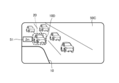
- vehicle
- display control
- speed
- information
- unit
- Prior art date
- Legal status (The legal status is an assumption and is not a legal conclusion. Google has not performed a legal analysis and makes no representation as to the accuracy of the status listed.)
- Ceased
Links
Images





Classifications
-
- B—PERFORMING OPERATIONS; TRANSPORTING
- B60—VEHICLES IN GENERAL
- B60R—VEHICLES, VEHICLE FITTINGS, OR VEHICLE PARTS, NOT OTHERWISE PROVIDED FOR
- B60R1/00—Optical viewing arrangements; Real-time viewing arrangements for drivers or passengers using optical image capturing systems, e.g. cameras or video systems specially adapted for use in or on vehicles
- B60R1/20—Real-time viewing arrangements for drivers or passengers using optical image capturing systems, e.g. cameras or video systems specially adapted for use in or on vehicles
- B60R1/22—Real-time viewing arrangements for drivers or passengers using optical image capturing systems, e.g. cameras or video systems specially adapted for use in or on vehicles for viewing an area outside the vehicle, e.g. the exterior of the vehicle
- B60R1/23—Real-time viewing arrangements for drivers or passengers using optical image capturing systems, e.g. cameras or video systems specially adapted for use in or on vehicles for viewing an area outside the vehicle, e.g. the exterior of the vehicle with a predetermined field of view
- B60R1/26—Real-time viewing arrangements for drivers or passengers using optical image capturing systems, e.g. cameras or video systems specially adapted for use in or on vehicles for viewing an area outside the vehicle, e.g. the exterior of the vehicle with a predetermined field of view to the rear of the vehicle
-
- G—PHYSICS
- G08—SIGNALLING
- G08G—TRAFFIC CONTROL SYSTEMS
- G08G1/00—Traffic control systems for road vehicles
- G08G1/16—Anti-collision systems
Definitions
- the present disclosure relates to a display control device and a display control method.
- the electronic mirror system displays on an in-vehicle monitor a side-rear image captured by an on-vehicle camera of the state of the area from the side to the rear of the vehicle, which the driver conventionally checked using a side mirror or visually.
- the driver of the vehicle can recognize the state of the vehicle from the side to the rear by looking at the image displayed on the in-vehicle monitor.
- Patent Document 1 discloses a warning display that acquires the relative position of a vehicle behind the side photographed by an in-vehicle camera, and sets the vehicle behind the side as the vehicle to be alerted.
- a caution ventilator is described that generates and displays information on a display. The driver can recognize the presence of the caution target vehicle by this display.
- the electronic mirror system displays captured images captured by imaging units provided at the left and right side mirrors of a vehicle on an in-vehicle monitor provided within the vehicle interior. Therefore, the driver who sees the captured image displayed on the in-vehicle monitor needs to correlate the situation behind the vehicle on the captured image with the situation behind the vehicle in real space, and must actually look in the side mirror. There was a problem in that it was difficult to intuitively understand the situation behind the vehicle in real space compared to the case where the vehicle was in use.
- the device described in Patent Document 1 uses a planar view image created separately from the image captured by the on-vehicle camera to show the driver information regarding the vehicle to the side and rear. For this reason, the planar view image does not provide a sense of realism during driving, and furthermore, it is difficult to intuitively grasp the situation behind the vehicle in real space.
- the present disclosure solves the above problems, and aims to provide a display control device and a display control method that can display information that helps grasp the situation behind the vehicle in real space.
- the display control device uses a side rear captured image in which a region to the side and rear of the first vehicle is captured to a second vehicle traveling in a region to the side or rear of the first vehicle.
- the speed of the second vehicle, the distance information between the second vehicle and the first vehicle, and the second vehicle are detected using the side rear vehicle detection unit that detects the vehicle and the detection information of the second vehicle.
- a side rear vehicle measurement unit that measures the estimated arrival time for the vehicle to reach the first vehicle
- a vehicle speed information acquisition unit that acquires the speed of the first vehicle
- a driving state determination unit that determines that the vehicle and the second vehicle are in the second driving state; and a driving state determining unit that determines that the vehicle and the second vehicle are in the second driving state;
- a display for generating display control information for superimposing display, and displaying the estimated arrival time superimposed on the side and rear captured image when the first vehicle and the second vehicle are in the second running state.
- a display control unit that generates control information.
- the first vehicle and the second vehicle when the speed of the first vehicle and the speed of the second vehicle traveling in a region to the side or rear of the first vehicle are less than a threshold value, the first vehicle and the second vehicle It is determined that the vehicle is in the first running state, and an image in which distance information between the first vehicle and the second vehicle is superimposed on the side and rear captured image is displayed.
- the speed of the first vehicle and the speed of the second vehicle are equal to or higher than the threshold values, it is determined that the first vehicle and the second vehicle are in the second driving state, and the second vehicle is in the first driving state.
- An image in which the estimated arrival time to reach the vehicle is superimposed on the side and rear captured image is displayed.
- the display control device can display information that helps the user understand the situation behind the vehicle in real space.
- FIG. 1 is a block diagram showing the configuration of a display control system according to Embodiment 1.
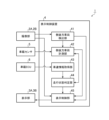
- FIG. 1 is a block diagram showing the configuration of a display control device according to Embodiment 1.
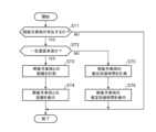
- FIG. 3 is a flowchart showing a display control method according to Embodiment 1.
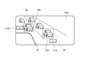
- FIG. 3 is a screen diagram showing an example (1) of a display screen in traffic jam driving mode.
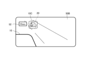
- FIG. 3 is a screen diagram showing an example (1) of a display screen in normal driving mode.
- 7 is a flowchart showing a modification of the display control method according to the first embodiment. It is a schematic diagram which shows typically the example (1) of the positional relationship between vehicles.
- FIG. 7 is a screen diagram showing an example (2) of a display screen in traffic jam driving mode.
- FIG. 1 is a block diagram showing the configuration of a display control system 1 according to the first embodiment.
- a display control system 1 displays an image (video) captured by an imaging unit 2A or 2B provided at the left and right side mirrors of a vehicle 10 on a display unit 3A or 3B provided in a vehicle interior.
- This is a system that displays
- the imaging unit 2A is provided at the position of the right side mirror, and images the right side and rear area of the vehicle 10.
- the image (video) captured by the imaging unit 2A is displayed on the display unit 3A.
- the imaging unit 2B is provided at the position of the left side mirror, and images the left side and rear area of the vehicle 10.
- the image (video) captured by the imaging section 2B is displayed on the display section 3B.
- the display unit 3A displays an image of the right side area of the vehicle 10, and the display unit 3B displays an image of the left side area of the vehicle 10.
- the display control device 4 generates display control information for displaying left, right, side, and rear images of the vehicle 10 (hereinafter referred to as side and rear images) captured by the imaging unit 2A or 2B.
- the display unit 3A or 3B displays a side and rear captured image of the vehicle 10 based on the display control information.
- the imaging units 2A and 2B function as electronic side mirrors.
- the display control device 4 generates display control information for displaying an image in which distance information between the vehicle 10 and the side rear vehicle is superimposed on the side rear captured image.
- the display unit 3A or 3B displays a side rear captured image on which distance information between the vehicle 10 and the side rear vehicle is superimposed, based on the display control information.
- the display control device 4 when the vehicle is normally traveling in real space, the movements of the vehicle 10 and the side rear vehicles change quickly, and the driver of the vehicle 10 approaches the vehicle 10 in the real space. This is a situation in which it is necessary to understand the movement of the vehicles behind and to the side.
- the display control device 4 generates display control information for displaying an image obtained by superimposing the estimated arrival time for the side rear vehicle to reach the vehicle 10 on the side rear captured image.
- the display unit 3A or 3B displays a side rear captured image on which an estimated arrival time for the side rear vehicle to reach the vehicle 10 is superimposed, based on the display control information. In this way, the display control device 4 presents the driver of the vehicle 10 with information (distance information or estimated arrival time) that helps the driver understand the situation behind the vehicle in real space.
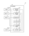
- FIG. 2 is a block diagram showing the configuration of the display control device 4 according to the first embodiment.
- the vehicle 10 shown in FIG. 1 is a first vehicle that includes an on-board sensor 5 and an on-board ECU 6 in addition to an imaging section 2A, an imaging section 2B, a display section 3A, and a display section 3B.
- Display control device 4 is mounted on vehicle 10.
- the on-vehicle sensor 5 is a sensor group composed of various sensors, and includes a GPS (Global Positioning System), a millimeter wave radar, a direction sensor, and the like.
- the on-vehicle ECU 6 is an electronic control unit that controls the running of the vehicle 10.
- the in-vehicle ECU 6 controls the speed of the vehicle 10 in response to an accelerator or brake operation by the driver.
- the display control device 4 includes a side rear vehicle detection section 41, a side rear vehicle measurement section 42, a vehicle speed information acquisition section 43, a driving state determination section 44, and a display control section 45.
- the side-rear vehicle detection unit 41 detects a side-rear vehicle traveling in a side or rear area of the vehicle 10 using a side-rear image in which the side and rear areas of the vehicle 10 are captured.
- the side rear vehicle detection unit 41 analyzes the side rear captured image captured by the imaging unit 2A or 2B frame by frame, and recognizes the side rear vehicle of the vehicle 10.
- image analysis techniques such as pattern matching are used for image analysis.
- the side rear vehicle is a second vehicle running on the side or rear of the vehicle 10.
- the side rear vehicle measurement unit 42 uses the detection information of the side rear vehicle by the on-vehicle sensor 5 to determine the speed of the side rear vehicle, the distance information between the side rear vehicle and the vehicle 10, and the estimated arrival time of the side rear vehicle reaching the vehicle 10. Measure time. For example, the side and rear vehicle measuring unit 42 measures the relative speed of the side and rear vehicle with respect to the vehicle 10 based on the time change in the distance to surrounding vehicles detected by the millimeter wave radar that is the in-vehicle sensor 5. When the relative speed of the side rear vehicle with respect to the vehicle 10 is a positive value, the side rear vehicle measuring unit 42 calculates the estimated arrival time for the side rear vehicle to reach the vehicle 10 using the relative speed of the side rear vehicle. do.
- the side rear vehicle measurement unit 42 receives information from the side rear vehicle through vehicle-to-vehicle communication, such as the speed of the side rear vehicle (ground speed), the distance information between the side rear vehicle and the vehicle 10, and the side rear vehicle reaching the vehicle 10. At least one of the estimated arrival times may be acquired. Further, the side rear vehicle measuring unit 42 measures the distance information between the side rear vehicle and the vehicle 10 from the time when the display control unit 45 determines the side rear vehicle for which distance information or estimated arrival time information is to be displayed, and measures the distance information between the side rear vehicle and the vehicle 10. The estimated arrival time for the rear vehicle to reach the vehicle 10 is measured.
- the vehicle speed information acquisition unit 43 acquires the speed of the vehicle 10. For example, the vehicle speed information acquisition unit 43 acquires the speed of the vehicle 10 from the in-vehicle ECU 6 that controls the traveling of the vehicle 10. The vehicle speed information of the vehicle 10 acquired by the vehicle speed information acquisition section 43 is output to the driving state determination section 44 . Further, the vehicle speed information acquisition unit 43 may acquire the speed of the vehicle 10 from a vehicle speed sensor mounted on the vehicle 10 instead of the on-vehicle ECU 6.
- the driving state determination unit 44 determines that the mode is traffic jam driving mode when the speed of the vehicle 10 and the speed of the side rear vehicle are less than the threshold value, and when the speed of the vehicle 10 and the speed of the side rear vehicle are equal to or higher than the threshold value. , it is determined that the vehicle is in normal driving mode.
- the traffic jam driving mode is a first driving state in which the speed of the vehicle 10 and the speed of the vehicles behind the vehicle are less than a threshold value. Note that the speed of the vehicle 10 and the speed of the side rear vehicle are absolute speeds, that is, ground speeds.
- the normal driving mode is a second driving state in which the speed of the vehicle 10 and the speed of the side rear vehicle are equal to or higher than a threshold value.
- the driving state determination unit 44 determines the speed of these vehicles. is compared with a threshold value (for example, 20 km/h). The driving state determining unit 44 determines that the vehicle is in traffic jam mode if both of these speeds are less than the threshold value, and determines that the vehicle is in the normal traveling mode if the speeds are equal to or higher than the threshold value. Information indicating the determination result of the driving condition is output from the driving condition determining section 44 to the display control section 45.
- the running state determination unit 44 uses the vehicle speed information of the vehicle 10 to determine whether the side rear vehicle Calculate the ground speed of
- the display control unit 45 generates display control information for superimposing and displaying distance information to the vehicle 10 on the side and rear captured images when the driving mode is in traffic congestion, and generates display control information for displaying distance information superimposed on the side and rear captured image when the driving mode is the normal driving mode. Display control information for superimposing and displaying the image on the side and rear captured image is generated.
- the display control unit 45 specifies the side rear vehicle detected by the side rear vehicle detection unit 41 from the side rear captured image based on the measurement information of the side rear vehicle measured by the side rear vehicle measurement unit 42.
- Display control information for displaying an image in which distance information or estimated arrival time information is superimposed near the side rear vehicle in the side rear captured image is generated.
- the display unit 3A or 3B displays a side and rear captured image on which distance information or estimated arrival time information is superimposed, based on the display control information.
- the display control device 4 displays the auxiliary information representing the distance or the estimated arrival time, which is at least one of the text and the image, superimposed on the side and rear captured image that is the live-action video.
- the driver who views the side-rear captured image displayed on the display unit 3A or 3B can intuitively grasp the situation behind the vehicle in real space without impairing the sense of realism during driving. .
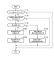
- FIG. 3 is a flowchart showing a display control method according to the first embodiment.
- the side and rear vehicle detection unit 41 detects a side and rear vehicle of the vehicle 10 using side and rear captured images continuously captured by the imaging unit 2A or 2B while the vehicle 10 is traveling. At this time, the side rear vehicle detection unit 41 enters a state of determining whether or not there is a side rear vehicle (step ST1). Note that the side and rear captured images captured by the imaging unit 2A or 2B are sequentially displayed on the display unit 3A or 3B. If a vehicle behind the vehicle 10 is not detected (step ST1; NO), the series of processes in FIG. 3 ends, and the processes starting from step ST1 are executed again.
- the vehicle measuring unit 42 measures the speed of the vehicle behind the vehicle using the detection information of the vehicle behind the vehicle.
- the vehicle speed information acquisition unit 43 acquires speed information of the vehicle 10.
- the driving state determination unit 44 uses the measurement information of the side rear vehicle by the side rear vehicle measurement unit 42 and the vehicle speed information of the vehicle 10 acquired by the vehicle speed information acquisition unit 43 to determine the speed of the vehicle 10 and the speed of the side rear vehicle. It is determined whether both are less than a certain speed (threshold value) (step ST2).
- the driving state determination unit 44 determines that the vehicle 10 and the side rear vehicle are in the traffic jam driving mode. In the traffic jam driving mode, the driving state determination unit 44 acquires distance information between the side rear vehicle and the vehicle 10 measured by the side rear vehicle measurement unit 42 (step ST3), and outputs the distance information to the display control unit 45. .
- the display control unit 45 When the display control unit 45 acquires the determination result information indicating that the mode is the traffic jam driving mode and the distance information between the side rear vehicle and the vehicle 10, the display control unit 45 adds the distance information to the side rear captured image that is being captured by the imaging unit 2A or 2B. Display control information for displaying the superimposed image is generated, and the generated display control information is output to the display section 3A or 3B. The display unit 3A or 3B displays the side and rear captured image on which the distance information is superimposed based on the display control information (step ST4).
- the display control unit 45 sequentially acquires the measurement information of the side rear vehicle by the side rear vehicle measurement unit 42 from the time when the distance information is superimposed and displayed on the side rear captured image, and the distance changes from time to time.
- the information may be displayed superimposed on the side and rear captured images.
- FIG. 4 is a screen diagram showing an example (1) of a display screen in traffic jam mode.
- the side and rear captured image 50A shown in FIG. 4 is an image captured by the imaging section 2B and displayed on the display section 3B.
- a plurality of side and rear vehicles including the vehicle 10A and the vehicle 10B are captured in the side and rear captured image 50A.
- the display control unit 45 When the distance information satisfies the first display condition, the display control unit 45 generates display control information for displaying the distance information superimposed on the side and rear captured image 50A. For example, when the distance indicated by the distance information is less than the threshold, the display control unit 45 generates display control information for superimposing and displaying the distance information on the side and rear captured image 50A.
- the display control unit 45 may highlight a vehicle displaying distance information in order to distinguish it from a vehicle displaying no distance information. For example, as shown in FIG. 4, frame line images 20 surrounding the vehicle 10A and the vehicle 10B are displayed. The driver of the vehicle 10 can intuitively understand that the vehicles 10A and 10B are running near the vehicle 10 by viewing the side rear captured image 50A. Note that, in addition to the frame line image 20, the highlighting may employ display processing such as changing the color of the vehicle, superimposing a blinking pattern on the vehicle, or making the frame line image 20 blink. Good too. In addition, the display control unit 45 may superimpose distance information from the vehicle 10 on all side rear vehicles shown in the side rear captured image 50A in the traffic jam driving mode.
- the driving state determination unit 44 determines that the vehicle 10 and the side rear vehicle are in the normal driving mode. In the normal driving mode, the driving state determination unit 44 acquires estimated arrival time information until the side rear vehicle reaches the vehicle 10 measured by the side rear vehicle measurement unit 42 (step ST5), and obtains the estimated arrival time information. is output to the display control section 45.
- the display control unit 45 When the display control unit 45 acquires the determination result information indicating that the mode is the normal driving mode and the estimated arrival time information for the side rear vehicle to reach the vehicle 10, the display control unit 45 displays the side rear captured image that the imaging unit 2A or 2B is currently capturing. Display control information for displaying an image on which estimated arrival time information is superimposed is generated, and the display control information is output to display section 3A or 3B. The display unit 3A or 3B displays the side and rear captured image on which the estimated arrival time information is superimposed, based on the display control information (step ST6).
- the display control unit 45 sequentially acquires the measurement information of the side rear vehicle by the side rear vehicle measurement unit 42 from the time when the estimated arrival time information is superimposed and displayed on the side rear captured image, and changes the information from time to time.
- the estimated arrival time may be superimposed and displayed on the side and rear captured images.
- FIG. 5 is a screen diagram showing an example (1) of the display screen in the normal driving mode.
- a side and rear captured image 50B shown in FIG. 5 is an image captured by the imaging section 2B and displayed on the display section 3B.
- the side-rear captured image 50B captures a vehicle 10C, which is a side-rear vehicle.
- the display control unit 45 When the estimated arrival time satisfies the second display condition, the display control unit 45 generates display control information for displaying the estimated arrival time superimposed on the side-rear captured image 50B. For example, when the time indicated by the estimated arrival time information is less than the threshold, the display control unit 45 generates display control information for displaying the estimated arrival time information in a superimposed manner on the side-rear captured image 50B.
- estimated arrival time information 52 is displayed in the side rear captured image 50B near the vehicle 10C for which the estimated arrival time of the vehicle 10 is "10 sec”. .
- the estimated arrival time information is displayed on a large number of side and rear vehicles, and it is possible to prevent the side and rear captured image 50B from becoming a complicated display.
- the display control unit 45 may highlight a vehicle displaying estimated arrival time information in order to distinguish it from a vehicle that does not display estimated arrival time information. For example, as shown in FIG. 5, a frame line image 20 surrounding the vehicle 10C is displayed. The driver of the vehicle 10 can intuitively understand that the vehicle 10C is approaching the vehicle 10 by looking at the side rear captured image 50B. Note that, in addition to the frame line image 20, the highlighting may employ display processing such as changing the color of the vehicle, superimposing a blinking pattern on the vehicle, or making the frame line image 20 blink. Good too. Further, the display control unit 45 may superimpose estimated arrival time information on all side rear vehicles shown in the side rear captured image 50B in the normal driving mode.
- the second display condition may specify a side rear vehicle for which the time indicated by the estimated arrival time information is equal to or greater than the threshold value.
- the display control unit 45 generates display control information for displaying the estimated arrival time information in the vicinity of the side rear vehicle whose time indicated by the estimated arrival time information is equal to or greater than the threshold value in the side rear captured image 50B. It turns out.
- FIG. 6 is a flowchart showing a modification of the display control method according to the first embodiment.
- the side and rear vehicle detection unit 41 detects a side and rear vehicle of the vehicle 10 using side and rear captured images continuously captured by the imaging unit 2A or 2B while the vehicle 10 is traveling. At this time, the side rear vehicle detection unit 41 enters a state of determining whether or not there is a rear vehicle in the same lane as the vehicle 10 (step ST1A). Note that the side and rear captured images captured by the imaging unit 2A or 2B are sequentially displayed on the display unit 3A or 3B. If a rear vehicle in the same lane is not detected (step ST1A; NO), the series of processes in FIG. 6 ends, and the processes starting from step ST1A are executed again.
- the side rear vehicle measurement unit 42 detects a rear vehicle traveling in the same lane as the vehicle 10 using the detection information of the side rear vehicle. Measure the speed of.
- the vehicle speed information acquisition unit 43 acquires speed information of the vehicle 10.
- the driving state determination unit 44 uses the measurement information of the rear vehicle by the side rear vehicle measurement unit 42 and the vehicle speed information of the vehicle 10 acquired by the vehicle speed information acquisition unit 43 to determine whether the speed of the vehicle 10 and the speed of the rear vehicle are both constant. It is determined whether the speed is less than the speed (threshold) (step ST2A).
- step ST2A If the speed of the vehicle 10 and the speed of the vehicle behind are both less than the certain speed (step ST2A; YES), the driving state determining unit 44 determines that the vehicle 10 and the vehicle behind are in the traffic jam driving mode. In the traffic jam driving mode, the driving state determination unit 44 acquires distance information between the vehicle 10 and a rear vehicle traveling in the same lane, and outputs the distance information to the display control unit 45.
- the display control unit 45 When the display control unit 45 acquires the determination result information indicating that the vehicle is in the traffic jam mode and the distance information between the rear vehicle and the vehicle 10, the display control unit 45 selects a rear image of the same lane that is being captured by the image capture unit 2A or 2B. Display control information is generated for displaying an image with distance information superimposed only on a rear vehicle that is running behind and is closest to the vehicle 10. The display unit 3A or 3B displays the side and rear captured image on which the distance information is superimposed based on the display control information (step ST3A).
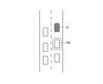
- FIG. 7 is a schematic diagram schematically showing an example (1) of the positional relationship between vehicles.
- the driver of the vehicle 10 wants to know whether the closest vehicle 10D traveling in the same lane is traveling at an appropriate distance. Therefore, distance information is displayed in the vicinity of the vehicle 10D that is in the congested traffic mode and is traveling in the same lane as the vehicle 10.
- the driving state determination unit 44 determines that the vehicle 10 and the side rear vehicle are in the normal driving mode. In the normal driving mode, the driving state determination unit 44 acquires estimated arrival time information until the side rear vehicle reaches the vehicle 10, which is measured by the side rear vehicle measurement unit 42 (step ST4A), and the estimated arrival time information. is output to the display control section 45.
- the display control unit 45 When the display control unit 45 acquires the determination result information indicating that the mode is the normal driving mode and the estimated arrival time information for the side rear vehicle to reach the vehicle 10, the display control unit 45 displays the side rear captured image that the imaging unit 2A or 2B is currently capturing. Display control information for displaying an image on which estimated arrival time information is superimposed is generated, and the generated display control information is output to display section 3A or 3B. The display unit 3A or 3B displays the side and rear captured image on which the estimated arrival time information is superimposed, based on the display control information (step ST5A).
- the display control unit 45 sequentially acquires the measurement information of the side rear vehicle by the side rear vehicle measurement unit 42 from the time when the estimated arrival time information is superimposed and displayed on the side rear captured image, and changes the information from time to time.
- the estimated arrival time may be superimposed and displayed on the side and rear captured images.
- the display control device 4 includes a processing circuit for executing the processing from step ST1 to step ST6 shown in FIG. 3.
- the processing circuit may be dedicated hardware, or may be a CPU (Central Processing Unit) that executes a program stored in memory.
- FIG. 9A is a block diagram showing the hardware configuration that realizes the functions of the display control device 4.
- FIG. 9B is a block diagram showing a hardware configuration that executes software that implements the functions of the display control device 4.
- an input interface 100 is an interface through which the display control device 4 relays information input from the imaging units 2A and 2B, the on-vehicle sensor 5, and the on-vehicle ECU 6.
- the output interface 101 is an interface that relays display control information output from the display control device 4 to the display units 3A and 3B.
- the processing circuit 102 may be, for example, a single circuit, a composite circuit, a programmed processor, a parallel programmed processor, or an ASIC (Application Specific Integrated Circuit). ), FPGA (Field-Programmable Gate Array), or a combination thereof.
- the functions of the side rear vehicle detection section 41, the side rear vehicle measurement section 42, the vehicle speed information acquisition section 43, the driving state determination section 44, and the display control section 45 included in the display control device 4 may be realized by separate processing circuits. , these functions may be realized by a single processing circuit.
- the display control device 4 includes a side rear vehicle detection section 41, a side rear vehicle measurement section 42, a vehicle speed information acquisition section 43, a running state determination section 44, and a display control section 45.
- the functions of are realized by software, firmware, or a combination of software and firmware. Note that software or firmware is written as a program and stored in the memory 104.
- the processor 103 reads out and executes the program stored in the memory 104 to detect the side and rear vehicle detection section 41, the side and rear vehicle measurement section 42, the vehicle speed information acquisition section 43, and the running state determination section that are included in the display control device 4. 44 and display control section 45.
- the display control device 4 includes a memory 104 for storing a program that, when executed by the processor 103, results in the processing from step ST1 to step ST6 shown in FIG. These programs cause the computer to execute the processing procedures or methods performed by the side and rear vehicle detection section 41, the side and rear vehicle measurement section 42, the vehicle speed information acquisition section 43, the driving state determination section 44, and the display control section 45.
- the memory 104 is a computer readable memory that stores programs for causing the computer to function as a side rear vehicle detection section 41, a side rear vehicle measurement section 42, a vehicle speed information acquisition section 43, a running state determination section 44, and a display control section 45. It may also be a storage medium.
- the memory 104 is, for example, RAM (Random Access Memory), ROM (Read Only Memory), flash memory, EPROM (Erasable Programmable Read Only Memory), Non-volatile or volatile semiconductor memory such as EEPROM (Electrically-EPROM), magnetic This includes discs, flexible discs, optical discs, compact discs, mini discs, DVDs, etc.
- the side rear vehicle detection section 41, side rear vehicle measurement section 42, vehicle speed information acquisition section 43, driving state determination section 44, and display control section 45 included in the display control device 4 are realized by dedicated hardware. , and other parts may be realized by software or firmware.
- the side rear vehicle detection section 41, the side rear vehicle measurement section 42, the vehicle speed information acquisition section 43, and the driving state determination section 44 realize their functions by the processing circuit 102, which is dedicated hardware, and the display control section 45, Functions are realized by the processor 103 reading and executing programs stored in the memory 104. In this way, the processing circuit can implement the above functions using hardware, software, firmware, or a combination thereof.
- the display control device 4 includes a side rear vehicle detection unit 41 that detects a side rear vehicle traveling at the side rear of the vehicle 10 using a side rear captured image of the vehicle 10; A side rear vehicle measurement unit 42 that measures the speed of the side rear vehicle, distance information from the vehicle 10, and estimated arrival time to the vehicle 10 using detection information of the side rear vehicle, and a vehicle speed that acquires the speed of the vehicle 10.
- the vehicle When the information acquisition unit 43 and the speed of the vehicle 10 and the speed of the side rear vehicle are less than a threshold value, it is determined that the mode is traffic jam driving mode, and if the speed of the vehicle 10 and the speed of the side rear vehicle are equal to or higher than the threshold value, The driving state determination unit 44 determines that the driving mode is normal, and generates display control information for displaying distance information to the vehicle 10 superimposed on the side and rear captured image when the driving mode is the traffic jam.
- the vehicle In the driving mode, the vehicle includes a display control unit 45 that generates display control information for displaying the estimated arrival time superimposed on the side and rear captured images.
- the display control device 4 In the congested traffic mode where the speed of the vehicle 10 and the speed of the vehicles behind it are less than the threshold, the movement of the vehicle 10 and surrounding vehicles changes slowly, and the driver of the vehicle 10 is unable to grasp the positional relationship between the vehicles in real space. This is a situation where it should be done.
- the display control device 4 generates display control information for displaying an image in which distance information between the vehicle 10 and surrounding vehicles is superimposed on a side and rear captured image.
- the display unit 3A or 3B displays a side and rear captured image on which distance information between the vehicle 10 and surrounding vehicles is superimposed, based on the display control information.
- the display control device 4 In the normal driving mode in which the speed of the vehicle 10 and the speed of the side rear vehicle are above the threshold values, the movement of the vehicle 10 and surrounding vehicles changes quickly, and the driver of the vehicle 10 approaches the vehicle 10 in real space. This is a situation in which it is necessary to understand the movements of approaching vehicles.
- the display control device 4 generates display control information for displaying an image obtained by superimposing the estimated arrival time of the surrounding vehicle to the vehicle 10 on the side-rear captured image.
- the display unit 3A or 3B displays a side-rear captured image on which the estimated arrival time of the surrounding vehicle to reach the vehicle 10 is superimposed, based on the display control information. In this way, the display control device 4 can display information (distance information or estimated arrival time) that helps the driver of the vehicle 10 understand the situation behind the vehicle in real space.
- the display control unit 45 when the vehicle 10D following the vehicle 10 in the same lane as the vehicle 10 and the vehicle 10 is in the congested traffic mode, the display control unit 45 is configured to display a vehicle that is closest to the vehicle 10 and that is the same as the vehicle 10. Display control information for superimposing and displaying distance information between vehicle 10D and vehicle 10 following on the same lane on side and rear captured image 50C is generated. The driver of the vehicle 10 can intuitively grasp the distance between the vehicle 10 and the vehicle 10D that is running following the vehicle 10 by viewing the side rear captured image 50C.
- a side rear vehicle detection unit 41 detects a side rear vehicle using a side rear captured image
- a side rear vehicle measurement unit 42 uses detection information of the side rear vehicle.
- the vehicle speed information acquisition unit 43 acquires the speed information of the vehicle 10
- the running state determination unit 44 measures the speed of the vehicle behind the vehicle 10, the distance information and estimated arrival time from the vehicle 10, and the driving state determination unit 44 measures the speed of the vehicle 10 and the estimated arrival time.
- the display control unit 45 If the speed of the vehicle behind is less than the threshold, it is determined that the driving mode is in traffic congestion, and if the speed of the vehicle 10 and the speed of the vehicle behind the vehicle are equal to or higher than the threshold, it is determined that the driving mode is normal, and the display control unit 45 generates display control information for superimposing and displaying distance information between the vehicle 10 and the side rear vehicle on the side rear captured image when the vehicle is in the traffic jam driving mode; Display control information for superimposing and displaying the estimated arrival time for the rear vehicle to reach the vehicle 10 on the side-rear captured image is generated.
- the display control device 4 executes the display control method, it is possible to display information that helps the user understand the situation behind the vehicle in real space.
- the display control unit 45 when the distance information satisfies the first display condition, the display control unit 45 generates display control information for superimposing and displaying the distance information on the side and rear captured images.
- display control information for displaying the estimated arrival time superimposed on the side and rear captured images is generated. Since only the information that satisfies the first display condition or the second display condition is displayed, the number of information superimposed on the side and rear captured images can be suppressed, and a complicated display can be prevented.
- FIG. 10 is a block diagram showing the configuration of a display control system 1A according to the second embodiment.
- the display control device 4A includes a side rear vehicle detection section 41A, a side rear vehicle measurement section 42, a vehicle speed information acquisition section 43, a driving state determination section 44A, a display control section 45A, and a blinker direction information acquisition section 46.
- the side and rear vehicle detection unit 41A uses the side and rear captured images in which the side and rear regions of the vehicle 10 are captured, and detects whether the vehicle is traveling in the side or rear region of the vehicle 10. Detects the vehicle behind you. Furthermore, the side rear vehicle detection unit 41A detects the lighting direction of a blinker mounted on the side rear vehicle. For example, the side rear vehicle detection unit 41A analyzes the side rear captured image captured by the imaging unit 2A or 2B frame by frame, and recognizes the side rear vehicle of the vehicle 10 and the lighting of the turn signal of the vehicle. For example, image analysis techniques such as pattern matching are used for image analysis.
- the driving state determination unit 44A determines that the vehicle 10 and the side rear vehicle are about to change lanes to the same lane. In this case, it is determined whether the vehicle 10 and the side rear vehicle are in the traffic jam driving mode or the normal driving mode based on whether the speed of the vehicle 10 and the speed of the side rear vehicle are less than a threshold value.
- the traffic jam driving mode is a first driving state in which the speed of the vehicle 10 and the speed of the side rear vehicle are less than a threshold value
- the normal driving mode is a second driving state in which the speed of the vehicle 10 and the speed of the side rear vehicle are equal to or higher than the threshold value. It is in running condition.
- the display control unit 45A generates display control information for superimposing and displaying distance information from the vehicle 10 on the side and rear captured images when the traffic jam driving mode is selected, and displays the estimated arrival time when the normal driving mode is used. Display control information to be displayed superimposed on the side-rear captured image is generated. For example, the display control unit 45A determines, based on the blinker direction information of the side rear vehicle detected by the side rear vehicle detection unit 41A, when there is a side rear vehicle that is about to change lanes to the same lane as the lane change destination of the vehicle 10. , generates display control information for displaying an image in which distance information or estimated arrival time information is superimposed in the vicinity of the side rear vehicle in the side rear captured image. The display unit 3A or 3B displays a side and rear captured image on which distance information or estimated arrival time information is superimposed, based on the display control information.
- the blinker direction information acquisition unit 46 acquires blinker direction information indicating the lighting direction of the blinkers mounted on the vehicle 10. For example, the blinker direction information acquisition unit 46 acquires blinker direction information of the vehicle 10 from the in-vehicle ECU 6 that controls traveling of the vehicle 10. The turn signal direction information acquired by the turn signal direction information acquisition section 46 is output to the driving state determination section 44A and the display control section 45A.
- the display control device 4A displays auxiliary information representing the distance or estimated arrival time in at least one of text and images only for the rear vehicle on the side that is about to change lanes to the same lane as the lane change destination of the vehicle 10. is displayed superimposed on the side-rear captured image.
- the driver who views the side-rear captured image displayed on the display unit 3A or 3B can intuitively grasp the situation behind the vehicle in real space without impairing the sense of realism during driving. .
- FIG. 11 is a flowchart showing a display control method according to the second embodiment.
- the driving state determination unit 44A determines whether the vehicle 10 is putting out the blinkers, that is, whether the vehicle 10 is turning on the blinkers, based on the blinker direction information acquired by the blinker direction information acquisition unit 46. (Step ST1B). If the vehicle 10 does not put out the turn signal (step ST1B; NO), the display control device 4A ends the series of processes shown in FIG. 11.
- the side and rear vehicle detection unit 41A uses the side and rear captured images continuously captured by the imaging unit 2A or 2B to determine whether the vehicle 10 is traveling. Detects a vehicle running in the lane two lanes next to the lane in which you are currently driving and a vehicle behind you that is using its blinker. At this time, the side rear vehicle detection unit 41A enters a state of determining whether or not the side rear vehicle exists (step ST2B). Note that the side and rear captured images captured by the imaging unit 2A or 2B are sequentially displayed on the display unit 3A or 3B.
- step ST2B If the vehicle 10 is traveling in the lane two lanes adjacent to the lane in which it is traveling and a rear vehicle on the side with its turn signal on is not detected (step ST2B; NO), the display control device 4A performs the series of processes shown in FIG. is finished once, and the process from step ST1B is repeated again.
- the side rear vehicle measurement unit 42 detects the side rear vehicle.
- the speed of the vehicle behind the vehicle is measured using the detected information.
- the vehicle speed information acquisition unit 43 acquires speed information of the vehicle 10.
- the driving state determination unit 44A uses the measurement information of the side rear vehicle by the side rear vehicle measurement unit 42 and the vehicle speed information of the vehicle 10 acquired by the vehicle speed information acquisition unit 43 to determine the speed of the vehicle 10 and the side rear vehicle. It is determined whether both speeds are less than a certain speed (threshold value) (step ST3B).
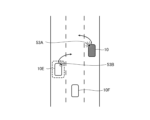
- FIG. 12 is a schematic diagram schematically showing example (2) of the positional relationship between vehicles.
- the driver of the vehicle 10 wants to know whether the vehicle 10E is traveling in a manner that may cause a collision with the vehicle 10. For example, in FIG. 12, the vehicle 10 is attempting to change to the center lane by turning on the left turn signal 53A.
- Vehicle 10F which is a side rear vehicle, is traveling in the center lane at a position far from vehicle 10. The vehicle 10E is about to turn on the right turn signal 53B and change to the center lane.
- the display control device 4A displays distance information or estimated arrival time for the vehicle 10E that is about to change lanes to the same lane as the lane to which the vehicle 10 is changing. By viewing this display, the driver of the vehicle 10 can intuitively grasp the presence of a vehicle behind or on the side with which there is a possibility of colliding when changing lanes.
- the driving state determination unit 44A determines that the vehicle 10 and the vehicle 10E are in the traffic jam driving mode. In the traffic jam driving mode, the driving state determination unit 44A acquires distance information between the vehicle 10E and the vehicle 10 measured by the side and rear vehicle measurement unit 42 (step ST4B), and outputs the distance information to the display control unit 45A.
- the display control unit 45A When the display control unit 45A acquires the determination result information indicating that the vehicle is in the congested traffic mode and the distance information between the vehicle 10E and the vehicle 10, the display control unit 45A superimposes the distance information on the side and rear captured image that is being captured by the imaging unit 2A or 2B. Display control information for displaying the image is generated, and the display control information is output to the display unit 3A or 3B. The display unit 3A or 3B displays the side and rear captured image on which the distance information is superimposed, based on the display control information (step ST5B).
- the display control unit 45A sequentially acquires the measurement information of the side rear vehicle by the side rear vehicle measurement unit 42 from the time when the distance information is superimposed and displayed on the side rear captured image, and displays the distance information that changes from time to time. It may be displayed superimposed on the side and rear captured images. By viewing this side rear captured image, the driver of the vehicle 10 can grasp the time change in the distance between the vehicle 10E and the vehicle 10 without losing the sense of realism of driving.
- the driving state determination unit 44A determines that the vehicle 10 and the vehicle 10E are in the normal driving mode. In the normal driving mode, the driving state determination unit 44A acquires estimated arrival time information until the vehicle 10E reaches the vehicle 10 measured by the side rear vehicle measurement unit 42 (step ST6B), and displays the estimated arrival time information. It is output to the control section 45A.
- the display control unit 45A When the display control unit 45A acquires the determination result information indicating that the vehicle is in the normal driving mode and the estimated arrival time information for the vehicle 10E to reach the vehicle 10, the display control unit 45A displays the side and rear captured image that the imaging unit 2A or 2B is currently capturing. Display control information for displaying an image on which estimated arrival time information is superimposed is generated, and the display control information is output to display section 3A or 3B. The display unit 3A or 3B displays the side and rear captured image on which the estimated arrival time information is superimposed, based on the display control information (step ST7B).
- the display control unit 45A sequentially acquires the measurement information of the side rear vehicle by the side rear vehicle measurement unit 42 from the time when the estimated arrival time information is superimposed and displayed on the side rear captured image, and changes the information from time to time.
- the estimated arrival time may be superimposed and displayed on the side and rear captured images.
- the display control unit 45A may also generate display control information for displaying the distance information superimposed on the side and rear captured images when the distance information satisfies the first display condition. For example, when the distance indicated by the distance information is less than the threshold value, the display control unit 45A generates display control information for displaying the distance information superimposed on the side and rear captured image. Based on this display control information, the display units 3A and 3B display distance information in a superimposed manner only for the side rear vehicle whose distance information satisfies the first display condition in the side rear captured image.
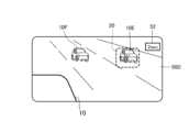
- FIG. 13 is a screen diagram showing an example (2) of the display screen in the normal driving mode.
- a side and rear captured image 50D shown in FIG. 13 is an image captured by the imaging section 2B and displayed on the display section 3B.
- Vehicle 10E and vehicle 10F are captured in side and rear captured image 50D.
- the display control unit 45A generates display control information for displaying the estimated arrival time information 52 in the side rear captured image 50D near the vehicle 10E that is about to change lanes to the same lane as the lane to which the vehicle 10 is changing. Based on this display control information, display units 3A and 3B display estimated arrival time information 52 in a superimposed manner near vehicle 10E in side-rear captured image 50D.
- the display control unit 45A may generate display control information for displaying the estimated arrival time superimposed on the side-rear captured image 50D. For example, the display control unit 45A generates display control information for superimposing and displaying the estimated arrival time information less than the threshold value on the side-rear captured image 50D.
- the display control unit 45A may highlight a vehicle displaying estimated arrival time information in order to distinguish it from a vehicle that does not display estimated arrival time information. For example, as shown in FIG. 13, a frame line image 20 surrounding the vehicle 10E is displayed. By looking at the side rear captured image 50D, the driver of the vehicle 10 can intuitively understand that there is a vehicle 10E that is about to change lanes into the same lane as the lane to which the vehicle 10 is changing. Note that, in addition to the frame line image 20, the highlighting may employ display processing such as changing the color of the vehicle, superimposing a blinking pattern on the vehicle, or making the frame line image 20 blink. Good too.
- the display control unit 45A may also superimpose estimated arrival time information on all side rear vehicles shown in the side rear captured image 50D in the normal driving mode. Furthermore, the second display condition may specify a side rear vehicle whose time indicated by the estimated arrival time information is equal to or greater than the threshold value. In this case, the display control unit 45A generates display control information for displaying the estimated arrival time information in the vicinity of the side rear vehicle whose time indicated by the estimated arrival time information is equal to or greater than the threshold value in the side rear captured image 50D. .
- FIG. 14 is a flowchart showing a modification of the display control method according to the second embodiment, and shows a case where both the vehicle 10 and the vehicle behind it are traveling at less than a certain speed, that is, in the traffic jam mode.
- the driving state determination unit 44A uses the measurement information of the side rear vehicle by the side rear vehicle measurement unit 42 and the vehicle speed information of the vehicle 10 acquired by the vehicle speed information acquisition unit 43 to determine the speed of the vehicle 10 and the speed of the side rear vehicle. It is determined that both of the speeds are less than a certain speed (threshold value) (step ST1C).
- the driving state determination unit 44A determines whether the vehicle 10 is putting out the blinkers, that is, whether the vehicle 10 is turning on the blinkers, based on the blinker direction information acquired by the blinker direction information acquisition unit 46. (Step ST2C). If the vehicle 10 does not put out the turn signal (step ST2C; NO), the display control device 4A ends the series of processes shown in FIG. 14.
- the side and rear vehicle detection unit 41A uses the side and rear captured images continuously captured by the imaging unit 2A or 2B to determine whether the vehicle 10 is traveling. Detects vehicles traveling in the lane adjacent to the lane in which you are currently driving. At this time, the side rear vehicle detection unit 41A enters a state of determining whether or not the side rear vehicle exists (step ST3C). Note that the side and rear captured images captured by the imaging unit 2A or 2B are sequentially displayed on the display unit 3A or 3B. If the side rear vehicle traveling in the adjacent lane is not detected (step ST3C; NO), the display control device 4A once ends the series of processes in FIG. 14 and repeats the process from step ST1C again.
- the driving state determination unit 44A detects the side rear vehicle running on the adjacent lane as measured by the side rear vehicle measurement unit 42. Among them, the side rear vehicle closest to the vehicle 10 is specified, distance information between the specified side rear vehicle and the vehicle 10 is acquired (step ST4C), and the distance information is output to the display control unit 45A.
- the display control unit 45A When the display control unit 45A acquires the determination result information indicating that the driving mode is in traffic jam mode and the distance information, the display control unit 45A displays the side rear vehicle closest to the vehicle 10 in the side rear captured image being captured by the imaging unit 2A or 2B. Display control information for displaying an image with distance information superimposed on the vicinity is generated, and the display control information is output to the display unit 3A or 3B.
- the display unit 3A or 3B displays a side rear captured image on which distance information is superimposed in the vicinity of the side rear vehicle closest to the vehicle 10, based on the display control information (step ST5C).
- FIG. 15 is a schematic diagram schematically showing an example (3) of the positional relationship between vehicles.
- the driver of the vehicle 10 wants to know whether there is enough space between the vehicles to avoid a collision with the vehicle 10G when the vehicle 10 changes lanes.
- the vehicle 10 turns on the left turn signal 53A and is about to change to the center lane.
- Vehicle 10G which is a rear vehicle on the side of the adjacent lane, is traveling at a position close to vehicle 10.
- the display control device 4A displays distance information for the vehicle 10G traveling in the adjacent lane and closest to the vehicle 10. By viewing this display, the driver of the vehicle 10 can intuitively grasp the presence of a vehicle behind or on the side with which there is a possibility of colliding when changing lanes.
- FIG. 16 is a screen diagram showing an example (3) of the display screen in traffic jam mode.
- a side and rear captured image 50E shown in FIG. 16 is an image captured by the imaging section 2B and displayed on the display section 3B.
- a plurality of side and rear vehicles including the vehicle 10G are captured in the side and rear captured image 50E.
- the display control unit 45A identifies a vehicle 10G that is running in the adjacent lane where the vehicle 10 is about to change lanes and is closest to the vehicle 10 among the plurality of side and rear vehicles, and displays distance information 51 in the vicinity of the vehicle 10G.
- Generate display control information for The display unit 3B displays the side and rear captured image 50E based on this display control information.
- the display control unit 45A may highlight a vehicle that displays distance information in order to distinguish it from a vehicle that does not display distance information. For example, as shown in FIG. 16, a frame line image 20 surrounding the vehicle 10G is displayed. By looking at the side rear captured image 50E, the driver of the vehicle 10 can intuitively determine the distance between the vehicle 10 and the vehicle 10G that is closest to the vehicle 10 while driving in the adjacent lane to which the vehicle 10 is changing lanes in the traffic jam mode. can be grasped. Note that, in addition to the frame line image 20, the highlighting may employ display processing such as changing the color of the vehicle, superimposing a blinking pattern on the vehicle, or making the frame line image 20 blink. Good too.
- the display control device 4A includes the blinker direction information acquisition unit 46 that acquires blinker direction information indicating the lighting direction of the blinkers mounted on the vehicle 10.
- the side rear vehicle detection unit 41A detects the lighting direction of the blinker mounted on the side rear vehicle.
- the driving state determination unit 44A determines that the vehicle 10 and the rear vehicle on the side are about to change lanes to the same lane based on the lighting direction of the turn signal of the vehicle 10 and the lighting direction of the blinker mounted on the side rear vehicle. If so, it is determined whether the vehicle 10 and the side rear vehicle are in the traffic jam driving mode or the normal driving mode based on whether the speed of the vehicle 10 and the speed of the side rear vehicle are less than a threshold value. Thereby, the driver of the vehicle 10 can intuitively grasp the presence of a vehicle on the side or rear with which there is a possibility of colliding when changing lanes.
- the driving state determination unit 44A determines whether the vehicle 10 is lit based on the lighting direction of the turn signal of the vehicle 10 indicated by the turn signal direction information and the lighting direction of the turn signal mounted on the vehicle 10E.
- the speed of the vehicle 10 and the speed of the vehicle 10E are less than the threshold value.
- the vehicle 10 and the vehicle 10E are in the traffic jam mode or the normal mode, it is determined whether the vehicle 10 or the vehicle 10E is in the traffic jam mode or the normal mode.
- a server that is an external device may include the display control device 4 or 4A
- the vehicle 10 may include a communication unit that communicates with the server instead of the display control device 4 or 4A.
- the communication unit acquires the display control information generated by the server, and the display units 3A and 3B display side and rear captured images based on the display control information acquired by the communication unit.
- an in-vehicle terminal mounted on the vehicle 10 includes some of the components of the display control device 4 or 4A, and the in-vehicle terminal and the display control device 4 or 4A cooperate to display the side and rear captured image. Good too.
- the display control device can be used, for example, in a vehicle electronic mirror system.
- 1, 1A display control system 2A, 2B imaging unit, 3A, 3B display unit, 4, 4A display control device, 5 in-vehicle sensor, 6 in-vehicle ECU, 10, 10A to 10G vehicle, 20 frame line image, 41, 41A side Rear vehicle detection unit, 42 Side rear vehicle measurement unit, 43 Vehicle speed information acquisition unit, 44, 44A Running state determination unit, 45, 45A Display control unit, 46 Turn signal direction information acquisition unit, 50A to 50E Side rear captured image, 51, 51A, 51B distance information, 52 estimated arrival time information, 53A, 53B blinker, 100 input interface, 101 output interface, 102 processing circuit, 103 processor, 104 memory.
Landscapes
- Engineering & Computer Science (AREA)
- Multimedia (AREA)
- Mechanical Engineering (AREA)
- Physics & Mathematics (AREA)
- General Physics & Mathematics (AREA)
- Traffic Control Systems (AREA)
Abstract
表示制御装置(4)は、車両(10)の側後方撮像画像を用いて、車両(10)の側後方を走行する側後方車両を検出する側後方車両検出部(41)と、側後方車両の検出情報を用いて、側後方車両の速度、車両(10)との距離情報および車両(10)に到達する推定到達時間を計測する側後方車両計測部(42)と、車両(10)の速度を取得する車速情報取得部(43)と、車両(10)の速度および側後方車両の速度が閾値未満である場合に、渋滞走行モードであると判定し、車両(10)の速度および側後方車両の速度が閾値以上である場合、通常走行モードであると判定する走行状態判定部(44)と、渋滞走行モードである場合、車両(10)との距離情報を側後方撮像画像に重畳して表示するための表示制御情報を生成し、通常走行モードである場合、推定到達時間を側後方撮像画像に重畳して表示するための表示制御情報を生成する表示制御部(45)を備える。
Description
本開示は、表示制御装置および表示制御方法に関する。
車載カメラを利用したシステムとして電子ミラーシステムがある。電子ミラーシステムは、従来、運転者がサイドミラーまたは目視で確認していた車両の側方から後方の領域の状態を車載カメラで撮像した側後方画像を車内モニタに表示するものである。車両の運転者は、車内モニタに表示された画像をみることにより、車両の側方から後方の状態を認識することが可能である。
電子ミラーシステムに関する従来の技術として、例えば、特許文献1には、車載カメラが撮像した側後方の車両との相対位置を取得し、側後方の車両を注意喚起対象車両とした注意喚起用の表示情報を生成して表示器に表示する注意換気装置が記載されている。運転者は、この表示により注意喚起対象車両の存在を認識することができる。
電子ミラーシステムは、車両の左右のサイドミラーの位置に設けられた撮像部によって撮像された撮像画像を車室内に設けられた車内モニタに表示するものである。このため、車内モニタに表示された撮像画像を見た運転者は、当該撮像画像上の車両側後方の状況と実空間の車両側後方の状況とを対応付ける必要があり、サイドミラーを実際に見る場合に比べて実空間の車両側後方の状況を直感的に把握しにくいという課題があった。
なお、特許文献1に記載された装置は、車載カメラが撮像した画像とは別に作成された平面視画像を用いて、側後方の車両に関する情報を運転者に示すものである。このため、当該平面視画像では、走行時の臨場感が得られず、さらに、実空間の車両側後方の状況も直感的に把握しにくい。
本開示は上記課題を解決するものであり、実空間の車両側後方の状況を把握する助けとなる情報を表示することができる、表示制御装置および表示制御方法を得ることを目的とする。
本開示に係る表示制御装置は、第1の車両の側方および後方の領域が撮像された側後方撮像画像を用いて、第1の車両の側方または後方の領域を走行している第2の車両を検出する側後方車両検出部と、第2の車両の検出情報を用いて、第2の車両の速度、第2の車両と第1の車両との間の距離情報および第2の車両が第1の車両に到達する推定到達時間を計測する側後方車両計測部と、第1の車両の速度を取得する車速情報取得部と、第1の車両の速度および第2の車両の速度が閾値未満である場合、第1の車両および第2の車両が第1の走行状態であると判定し、第1の車両の速度および第2の車両の速度が閾値以上である場合、第1の車両および第2の車両が第2の走行状態であると判定する走行状態判定部と、第1の車両および第2の車両が第1の走行状態である場合、距離情報を側後方撮像画像に重畳して表示するための表示制御情報を生成し、第1の車両および第2の車両が第2の走行状態である場合、推定到達時間を側後方撮像画像に重畳して表示するための表示制御情報を生成する表示制御部と、を備える。
本開示によれば、第1の車両の速度と、第1の車両の側方または後方の領域を走行する第2の車両の速度とが閾値未満である場合に、第1の車両および第2の車両が第1の走行状態であると判定されて、第1の車両と第2の車両との間の距離情報を側後方撮像画像に重畳した画像が表示される。第1の車両の速度および第2の車両の速度が閾値以上である場合、第1の車両および第2の車両が第2の走行状態であると判定されて、第2の車両が第1の車両に到達する推定到達時間を側後方撮像画像に重畳した画像が表示される。
このように、本開示に係る表示制御装置は、実空間の車両側後方の状況を把握する助けとなる情報を表示することができる。
このように、本開示に係る表示制御装置は、実空間の車両側後方の状況を把握する助けとなる情報を表示することができる。
実施の形態1.
図1は、実施の形態1に係る表示制御システム1の構成を示すブロック図である。図1において、表示制御システム1は、車両10が備える左右のサイドミラーの位置に設けられた撮像部2Aまたは2Bによって撮像された画像(映像)を、車室内に設けられた表示部3Aまたは3Bに表示するシステムである。撮像部2Aは、右側のサイドミラーの位置に設けられ、車両10の右側方および後方の領域を撮像する。撮像部2Aによって撮像された画像(映像)は、表示部3Aに表示される。撮像部2Bは、左側のサイドミラーの位置に設けられ、車両10の左側方および後方の領域を撮像する。撮像部2Bによって撮像された画像(映像)は、表示部3Bに表示される。表示部3Aは、車両10の右側の領域の画像を表示し、表示部3Bは、車両10の左側の領域の画像を表示する。
図1は、実施の形態1に係る表示制御システム1の構成を示すブロック図である。図1において、表示制御システム1は、車両10が備える左右のサイドミラーの位置に設けられた撮像部2Aまたは2Bによって撮像された画像(映像)を、車室内に設けられた表示部3Aまたは3Bに表示するシステムである。撮像部2Aは、右側のサイドミラーの位置に設けられ、車両10の右側方および後方の領域を撮像する。撮像部2Aによって撮像された画像(映像)は、表示部3Aに表示される。撮像部2Bは、左側のサイドミラーの位置に設けられ、車両10の左側方および後方の領域を撮像する。撮像部2Bによって撮像された画像(映像)は、表示部3Bに表示される。表示部3Aは、車両10の右側の領域の画像を表示し、表示部3Bは、車両10の左側の領域の画像を表示する。
表示制御装置4は、撮像部2Aまたは2Bにより撮像された車両10の左右側方および後方の撮像画像(以下、側後方撮像画像という。)を表示するための表示制御情報を生成する。表示部3Aまたは3Bは、表示制御情報に基づいて、車両10の側後方撮像画像を表示する。このように、表示制御システム1において、撮像部2Aおよび2Bは、電子化されたサイドミラーとして機能する。
ただし、表示部3Aまたは3Bに表示された画像では、サイドミラーを直接見る場合に比べて距離感が掴みにくく、車両10の運転者は、実空間における車両10の側方または後方の少なくとも一方(以下、側後方という。)の状況を直感的に把握しにくい。
そこで、表示制御システム1では、表示部3Aまたは3Bに表示される側後方撮像画像に対して、運転者が実空間における車両10の側後方の状況を把握する助けとなる情報を付与する。
そこで、表示制御システム1では、表示部3Aまたは3Bに表示される側後方撮像画像に対して、運転者が実空間における車両10の側後方の状況を把握する助けとなる情報を付与する。
例えば、実空間において車両の通行が渋滞している状況である場合は、車両10および車両10の側後方を走行する車両(以下、側後方車両という。)のそれぞれの動きの変化が遅く、車両10の運転者は、実空間における車両同士の位置関係を把握すべき状況である。この場合、表示制御装置4は、車両10と側後方車両との距離情報を側後方撮像画像に重畳した画像を表示するための表示制御情報を生成する。表示部3Aまたは3Bは、上記表示制御情報に基づいて、車両10と側後方車両との距離情報が重畳された側後方撮像画像を表示する。
一方、実空間において車両が通常走行している状況である場合は、車両10および側後方車両のそれぞれの動きの変化が速く、車両10の運転者は、実空間において車両10に接近してくる側後方車両の動きを把握すべき状況である。この場合、表示制御装置4は、側後方車両が車両10に到達する推定到達時間を側後方撮像画像に重畳した画像を表示するための表示制御情報を生成する。表示部3Aまたは3Bは、上記表示制御情報に基づいて、側後方車両が車両10に到達する推定到達時間が重畳された側後方撮像画像を表示する。このように、表示制御装置4は、実空間の車両側後方の状況を把握する助けとなる情報(距離情報または推定到達時間)を、車両10の運転者に提示するものである。
図2は、実施の形態1に係る表示制御装置4の構成を示すブロック図である。例えば、図1に示した車両10は、撮像部2A、撮像部2B、表示部3Aおよび表示部3Bに加えて、車載センサ5、および車載ECU6を備えた第1の車両である。表示制御装置4は、車両10に搭載される。車載センサ5は、各種のセンサから構成されるセンサ群であり、GPS(Global Positioning System)、ミリ波レーダおよび方位センサ等が含まれる。車載ECU6は、車両10の走行を制御する電子制御ユニットである。例えば、車載ECU6は、運転者によるアクセルまたはブレーキ操作に応じて、車両10の速度を制御する。
表示制御装置4は、側後方車両検出部41、側後方車両計測部42、車速情報取得部43、走行状態判定部44および表示制御部45を備える。側後方車両検出部41は、車両10の側方および後方の領域が撮像された側後方撮像画像を用いて、車両10の側方または後方の領域を走行している側後方車両を検出する。例えば、側後方車両検出部41は、撮像部2Aまたは2Bが撮像する側後方撮像画像をフレームごとに画像解析し、車両10の側後方車両を認識する。画像解析には、例えば、パターンマッチング等の画像解析技術が用いられる。なお、側後方車両は、車両10の側方または後方を走行している第2の車両である。
側後方車両計測部42は、車載センサ5による側後方車両の検出情報を用いて、側後方車両の速度、側後方車両と車両10との距離情報および側後方車両が車両10に到達する推定到達時間を計測する。例えば、側後方車両計測部42は、車載センサ5であるミリ波レーダが検出した周辺車両との距離の時間変化に基づいて、車両10に対する側後方車両の相対速度を計測する。車両10に対する側後方車両の相対速度が正の値である場合に、側後方車両計測部42は、側後方車両の相対速度を用いて、側後方車両が車両10に到達する推定到達時間を算出する。
また、側後方車両計測部42は、車車間通信で側後方車両から、側後方車両の速度(対地速度)、側後方車両と車両10との距離情報、および側後方車両が車両10に到達する推定到達時間の少なくとも一つを取得してもよい。
さらに、側後方車両計測部42は、表示制御部45により距離情報または推定到達時間情報を表示する側後方車両が決定された時点から、側後方車両と車両10との距離情報を計測し、側後方車両が車両10に到達する推定到達時間を計測する。
さらに、側後方車両計測部42は、表示制御部45により距離情報または推定到達時間情報を表示する側後方車両が決定された時点から、側後方車両と車両10との距離情報を計測し、側後方車両が車両10に到達する推定到達時間を計測する。
車速情報取得部43は、車両10の速度を取得する。例えば、車速情報取得部43は、車両10の走行を制御する車載ECU6から、車両10の速度を取得する。車速情報取得部43が取得した車両10の車速情報は、走行状態判定部44に出力される。また、車速情報取得部43は、車載ECU6ではなく、車両10に搭載された車速センサから、車両10の速度を取得してもよい。
走行状態判定部44は、車両10の速度および側後方車両の速度が閾値未満である場合に、渋滞走行モードであると判定し、車両10の速度および側後方車両の速度が閾値以上であれば、通常走行モードであると判定する。渋滞走行モードは、車両10の速度および側後方車両の速度が閾値未満である第1の走行状態である。なお、車両10の速度および側後方車両の速度は、絶対的な速度、すなわち対地速度である。通常走行モードは、車両10の速度および側後方車両の速度が閾値以上である第2の走行状態である。
例えば、走行状態判定部44は、車速情報取得部43から車両10の速度を示す車速情報を取得し、側後方車両計測部42から側後方車両の速度を示す計測情報を取得すると、これらの速度を閾値(例えば、20km/h)と比較する。走行状態判定部44は、これらの速度がともに閾値未満であれば、渋滞走行モードであると判定し、閾値以上であると通常走行モードであると判定する。この走行状態の判定結果を示す情報は、走行状態判定部44から表示制御部45に出力される。また、走行状態判定部44は、側後方車両計測部42が計測した側後方車両の速度が、車両10に対する側後方車両の相対速度であった場合、車両10の車速情報を用いて側後方車両の対地速度を算出する。
表示制御部45は、渋滞走行モードである場合に、車両10との距離情報を側後方撮像画像に重畳して表示するための表示制御情報を生成し、通常走行モードである場合、推定到達時間を側後方撮像画像に重畳して表示するための表示制御情報を生成する。例えば、表示制御部45は、側後方車両計測部42が計測した側後方車両の計測情報に基づいて、側後方車両検出部41が側後方撮像画像から検出した側後方車両を特定することにより、側後方撮像画像における側後方車両の近傍に距離情報または推定到達時間情報を重畳した画像を表示するための表示制御情報を生成する。表示部3Aまたは3Bは、表示制御情報に基づいて、距離情報または推定到達時間情報が重畳された側後方撮像画像を表示する。
このように、表示制御装置4は、テキストまたは画像の少なくとも一方で距離または推定到達時間を表した補助情報を、実写映像である側後方撮像画像に重畳させて表示する。これにより、表示部3Aまたは3Bに表示された側後方撮像画像を見た運転者は、走行時の臨場感を損なわずに、実空間の車両側後方の状況を直感的に把握することができる。
図3は、実施の形態1に係る表示制御方法を示すフローチャートである。
側後方車両検出部41は、車両10が走行している間、撮像部2Aまたは2Bによって連続的に撮像された側後方撮像画像を用いて、車両10の側後方車両の検出を行う。このとき、側後方車両検出部41は側後方車両が存在するか否かの判定状態となる(ステップST1)。なお、撮像部2Aまたは2Bにより撮像された側後方撮像画像は、表示部3Aまたは3Bに順次表示される。車両10の側後方車両が検出されない場合(ステップST1;NO)、図3の一連の処理が終了し、再びステップST1からの処理が実行される。
側後方車両検出部41は、車両10が走行している間、撮像部2Aまたは2Bによって連続的に撮像された側後方撮像画像を用いて、車両10の側後方車両の検出を行う。このとき、側後方車両検出部41は側後方車両が存在するか否かの判定状態となる(ステップST1)。なお、撮像部2Aまたは2Bにより撮像された側後方撮像画像は、表示部3Aまたは3Bに順次表示される。車両10の側後方車両が検出されない場合(ステップST1;NO)、図3の一連の処理が終了し、再びステップST1からの処理が実行される。
車両10の側後方車両が検出された場合(ステップST1;YES)、側後方車両計測部42が、側後方車両の検出情報を用いて側後方車両の速度を計測する。車速情報取得部43は、車両10の速度情報を取得する。走行状態判定部44は、側後方車両計測部42による側後方車両の計測情報と、車速情報取得部43が取得した車両10の車速情報とを用いて、車両10の速度および側後方車両の速度がともに一定速度(閾値)未満であるか否かを判定する(ステップST2)。
車両10の速度および側後方車両の速度がともに一定速度未満である場合(ステップST2;YES)、走行状態判定部44は、車両10および側後方車両が渋滞走行モードであると判定する。渋滞走行モードにおいて、走行状態判定部44は、側後方車両計測部42が計測した側後方車両と車両10との距離情報を取得し(ステップST3)、当該距離情報を表示制御部45に出力する。
表示制御部45は、渋滞走行モードであることを示す判定結果情報と、側後方車両と車両10との距離情報とを取得すると、撮像部2Aまたは2Bが撮像中の側後方撮像画像に距離情報を重畳した画像を表示するための表示制御情報を生成し、生成した表示制御情報を表示部3Aまたは3Bに出力する。表示部3Aまたは3Bは、表示制御情報に基づいて距離情報が重畳された側後方撮像画像を表示する(ステップST4)。
また、表示制御部45は、側後方撮像画像に距離情報を重畳して表示させた時点から、側後方車両計測部42による側後方車両の計測情報を順次取得して、時々刻々と変化する距離情報を側後方撮像画像に重畳して表示させてもよい。この側後方撮像画像を見ることにより、車両10の運転者は、走行の臨場感を損なうことなく、側後方車両と車両10との距離の時間変化を把握することができる。
図4は、渋滞走行モードの表示画面の例(1)を示す画面図である。図4に示す側後方撮像画像50Aは、撮像部2Bによって撮像されて表示部3Bに表示された画像である。側後方撮像画像50Aには、車両10Aおよび車両10Bを含む複数の側後方車両が撮像されている。表示制御部45は、距離情報が第1表示条件を満たす場合、距離情報を側後方撮像画像50Aに重畳して表示するための表示制御情報を生成する。例えば、距離情報が示す距離が閾値未満である場合、表示制御部45は、距離情報を側後方撮像画像50Aに重畳して表示するための表示制御情報を生成する。
上記閾値が「3m」である場合、図4に示すように、側後方撮像画像50Aにおいて、車両10との距離が「1m」である車両10Aの近傍に距離情報51Aが表示され、車両10との距離が「2m」である車両10Bの近傍に距離情報51Bが表示される。これにより、多数の側後方車両に距離情報が表示されて、側後方撮像画像50Aが煩雑な表示になることを防止できる。
また、表示制御部45は、距離情報を表示しない車両と区別するため、距離情報を表示した車両を強調表示させてもよい。例えば、図4に示すように、車両10Aおよび車両10Bをそれぞれ囲む枠線画像20を表示させる。車両10の運転者は、側後方撮像画像50Aを見ることにより、車両10の近くを車両10Aおよび10Bが走行していることを直感的に把握することができる。なお、強調表示には、枠線画像20以外に、例えば、車両の色を変更する、車両に対して点滅パターンを重畳する、あるいは、枠線画像20を点滅させる、といった表示処理を採用してもよい。
また、表示制御部45は、渋滞走行モードにおいて、側後方撮像画像50Aに映る全ての側後方車両に対して車両10との距離情報を重畳させてもよい。
また、表示制御部45は、渋滞走行モードにおいて、側後方撮像画像50Aに映る全ての側後方車両に対して車両10との距離情報を重畳させてもよい。
一方、車両10の速度および側後方車両の速度がともに一定速度以上である場合(ステップST2;NO)、走行状態判定部44は、車両10および側後方車両が通常走行モードであると判定する。通常走行モードにおいて、走行状態判定部44は、側後方車両計測部42が計測した、側後方車両が車両10に到達するまでの推定到達時間情報を取得し(ステップST5)、当該推定到達時間情報を表示制御部45に出力する。
表示制御部45は、通常走行モードであることを示す判定結果情報と、側後方車両が車両10に到達する推定到達時間情報とを取得すると、撮像部2Aまたは2Bが撮像中の側後方撮像画像に推定到達時間情報を重畳した画像を表示するための表示制御情報を生成して、表示制御情報を表示部3Aまたは3Bに出力する。
表示部3Aまたは3Bは、表示制御情報に基づいて、推定到達時間情報が重畳された側後方撮像画像を表示する(ステップST6)。
表示部3Aまたは3Bは、表示制御情報に基づいて、推定到達時間情報が重畳された側後方撮像画像を表示する(ステップST6)。
また、表示制御部45は、側後方撮像画像に推定到達時間情報を重畳して表示させた時点から、側後方車両計測部42による側後方車両の計測情報を順次取得して、時々刻々と変化する推定到達時間を側後方撮像画像に重畳して表示させてもよい。この側後方撮像画像を見ることにより、車両10の運転者は、走行の臨場感を損なうことなく、側後方車両が車両10に到達する時間の変化を把握することができる。
図5は、通常走行モードの表示画面の例(1)を示す画面図である。図5に示す側後方撮像画像50Bは、撮像部2Bによって撮像されて表示部3Bに表示された画像である。側後方撮像画像50Bには、側後方車両である車両10Cが撮像されている。表示制御部45は、推定到達時間が第2表示条件を満たす場合、推定到達時間を側後方撮像画像50Bに重畳して表示するための表示制御情報を生成する。例えば、推定到達情報が示す時間が閾値未満である場合、表示制御部45は、推定到達時間情報を側後方撮像画像50Bに重畳して表示するための表示制御情報を生成する。
上記閾値が「15sec」である場合、図5に示すように、側後方撮像画像50Bにおいて、車両10の推定到達時間が「10sec」である車両10Cの近傍に推定到達時間情報52が表示される。これにより、多数の側後方車両に推定到達時間情報が表示され、側後方撮像画像50Bが煩雑な表示になることを防止できる。
また、表示制御部45は、推定到達時間情報を表示しない車両と区別するため、推定到達時間情報を表示した車両を強調表示させてもよい。例えば、図5に示すように、車両10Cを囲む枠線画像20を表示させる。車両10の運転者は、側後方撮像画像50Bを見ることで、車両10に接近している車両10Cが存在することを、直感的に把握することができる。
なお、強調表示には、枠線画像20以外に、例えば、車両の色を変更する、車両に対して点滅パターンを重畳する、あるいは、枠線画像20を点滅させる、といった表示処理を採用してもよい。
また、表示制御部45は、通常走行モードにおいて、側後方撮像画像50Bに映る全ての側後方車両に対して推定到達時間情報を重畳させてもよい。
なお、強調表示には、枠線画像20以外に、例えば、車両の色を変更する、車両に対して点滅パターンを重畳する、あるいは、枠線画像20を点滅させる、といった表示処理を採用してもよい。
また、表示制御部45は、通常走行モードにおいて、側後方撮像画像50Bに映る全ての側後方車両に対して推定到達時間情報を重畳させてもよい。
また、第2表示条件は、推定到達時間情報が示す時間が上記閾値以上である側後方車両を特定するものであってもよい。この場合、表示制御部45は、側後方撮像画像50Bにおいて、推定到達時間情報が示す時間が上記閾値以上である側後方車両の近傍に推定到達時間情報を表示するための表示制御情報を生成することになる。
次に、実施の形態1に係る表示制御方法の変形例について説明する。
図6は、実施の形態1に係る表示制御方法の変形例を示すフローチャートである。
側後方車両検出部41は、車両10が走行している間、撮像部2Aまたは2Bによって連続的に撮像された側後方撮像画像を用いて、車両10の側後方車両の検出を行う。このとき、側後方車両検出部41は、車両10と同一車線に後方車両が存在するか否かの判定状態となる(ステップST1A)。なお、撮像部2Aまたは2Bにより撮像された側後方撮像画像は、表示部3Aまたは3Bに順次表示される。同一車線の後方車両が検出されない場合(ステップST1A;NO)、図6の一連の処理が終了し、再びステップST1Aからの処理が実行される。
図6は、実施の形態1に係る表示制御方法の変形例を示すフローチャートである。
側後方車両検出部41は、車両10が走行している間、撮像部2Aまたは2Bによって連続的に撮像された側後方撮像画像を用いて、車両10の側後方車両の検出を行う。このとき、側後方車両検出部41は、車両10と同一車線に後方車両が存在するか否かの判定状態となる(ステップST1A)。なお、撮像部2Aまたは2Bにより撮像された側後方撮像画像は、表示部3Aまたは3Bに順次表示される。同一車線の後方車両が検出されない場合(ステップST1A;NO)、図6の一連の処理が終了し、再びステップST1Aからの処理が実行される。
車両10と同一車線に後方車両が検出された場合(ステップST1A;YES)、側後方車両計測部42が、側後方車両の検出情報を用いて、車両10と同一車線を走行している後方車両の速度を計測する。車速情報取得部43は、車両10の速度情報を取得する。走行状態判定部44は、側後方車両計測部42による後方車両の計測情報と車速情報取得部43が取得した車両10の車速情報とを用いて、車両10の速度および後方車両の速度がともに一定速度(閾値)未満であるか否かが判定される(ステップST2A)。
車両10の速度および後方車両の速度がともに一定速度未満である場合(ステップST2A;YES)、走行状態判定部44は、車両10および後方車両が渋滞走行モードであると判定する。渋滞走行モードにおいて、走行状態判定部44は、同一車線を走行する後方車両と車両10との距離情報を取得し、距離情報を表示制御部45に出力する。
表示制御部45は、渋滞走行モードであることを示す判定結果情報と、後方車両と車両10との距離情報を取得すると、撮像部2Aまたは2Bが撮像中の後方撮像画像のうち、同一車線の後方を走行しかつ車両10に最も近い後方車両にのみ、距離情報を重畳した画像を表示するための表示制御情報を生成する。表示部3Aまたは3Bは、表示制御情報に基づいて、距離情報が重畳された側後方撮像画像を表示する(ステップST3A)。
また、表示制御部45は、側後方撮像画像に距離情報を重畳して表示させた時点から、側後方車両計測部42による側後方車両の計測情報を順次取得して、時々刻々と変化する距離情報を側後方撮像画像に重畳して表示させてもよい。この側後方撮像画像を見ることにより、車両10の運転者は、走行の臨場感を損なうことなく、側後方車両と車両10との距離の時間変化を把握することができる。
図7は、車両同士の位置関係の例(1)を模式的に示す模式図である。図7に示すように、渋滞走行モードである場合、車両10の運転者は、同一車線を走行する最も近い車両10Dが適切な車両間隔で走行しているかどうかを把握したい。そこで、渋滞走行モードで、かつ、車両10の同一車線を走行する車両10Dの近傍に距離情報を表示する。
図8は、渋滞走行モードの表示画面の例(2)を示す画面図である。図8に示す側後方撮像画像50Cは、撮像部2Bによって撮像されて表示部3Bに表示された画像である。側後方撮像画像50Cには、車両10Dを含む複数の側後方車両が撮像されている。表示制御部45は、複数の側後方車両のうち、車両10と同一車線を走行する車両10Dに対して、距離情報を表示するための表示制御情報を生成する。例えば、側後方撮像画像50Cにおいて、車両10と同一車線を走行し、かつ車両10に最も近い車両10Dの近傍に距離情報51が表示される。
また、表示制御部45は、距離情報を表示しない車両と区別するために距離情報を表示した車両を強調表示させてもよい。例えば、図8に示すように、車両10Dを囲む枠線画像20を表示させる。車両10の運転者は、側後方撮像画像50Cを見ることにより、車両10に後続して走行する車両10Dとの間隔を直感的に把握することができる。
なお、強調表示には、枠線画像20以外に、例えば、車両の色を変更する、車両に対して点滅パターンを重畳する、あるいは、枠線画像20を点滅させる、といった表示処理を採用してもよい。
なお、強調表示には、枠線画像20以外に、例えば、車両の色を変更する、車両に対して点滅パターンを重畳する、あるいは、枠線画像20を点滅させる、といった表示処理を採用してもよい。
一方、車両10の速度および後方車両の速度がともに一定速度以上である場合(ステップST2A;NO)、走行状態判定部44は、車両10および側後方車両が通常走行モードであると判定する。通常走行モードにおいて、走行状態判定部44は、側後方車両計測部42が計測した、側後方車両が車両10に到達するまでの推定到達時間情報を取得し(ステップST4A)、当該推定到達時間情報を表示制御部45に出力する。
表示制御部45は、通常走行モードであることを示す判定結果情報と、側後方車両が車両10に到達する推定到達時間情報を取得すると、撮像部2Aまたは2Bが撮像中の側後方撮像画像に推定到達時間情報を重畳した画像を表示するための表示制御情報を生成し、生成した表示制御情報を表示部3Aまたは3Bに出力する。表示部3Aまたは3Bは、表示制御情報に基づいて、推定到達時間情報が重畳された側後方撮像画像を表示する(ステップST5A)。
また、表示制御部45は、側後方撮像画像に推定到達時間情報を重畳して表示させた時点から、側後方車両計測部42による側後方車両の計測情報を順次取得して、時々刻々と変化する推定到達時間を側後方撮像画像に重畳して表示させてもよい。この側後方撮像画像を見ることにより、車両10の運転者は、走行の臨場感を損なうことなく、側後方車両が車両10に到達する時間の変化を把握することができる。
次に、表示制御装置の機能を実現するハードウェア構成について説明する。
表示制御装置4が備える、側後方車両検出部41、側後方車両計測部42、車速情報取得部43、走行状態判定部44および表示制御部45の機能は、処理回路により実現される。すなわち、表示制御装置4は、図3に示したステップST1からステップST6までの処理を実行するための処理回路を備える。処理回路は、専用のハードウェアであってもよいが、メモリに記憶されたプログラムを実行するCPU(Central Processing Unit)であってもよい。
表示制御装置4が備える、側後方車両検出部41、側後方車両計測部42、車速情報取得部43、走行状態判定部44および表示制御部45の機能は、処理回路により実現される。すなわち、表示制御装置4は、図3に示したステップST1からステップST6までの処理を実行するための処理回路を備える。処理回路は、専用のハードウェアであってもよいが、メモリに記憶されたプログラムを実行するCPU(Central Processing Unit)であってもよい。
図9Aは、表示制御装置4の機能を実現するハードウェア構成を示すブロック図である。図9Bは、表示制御装置4の機能を実現するソフトウェアを実行するハードウェア構成を示すブロック図である。図9Aおよび図9Bにおいて、入力インタフェース100は、表示制御装置4が、撮像部2Aおよび2B、車載センサ5および車載ECU6から入力する情報を中継するインタフェースである。出力インタフェース101は、表示制御装置4から表示部3Aおよび3Bへ出力される表示制御情報を中継するインタフェースである。
処理回路が図9Aに示す専用のハードウェアの処理回路102である場合、処理回路102は、例えば、単一回路、複合回路、プログラム化したプロセッサ、並列プログラム化したプロセッサ、ASIC(Application Specific Integrated Circuit)、FPGA(Field-Programmable Gate Array)またはこれらを組み合わせたものが該当する。
表示制御装置4が備える、側後方車両検出部41、側後方車両計測部42、車速情報取得部43、走行状態判定部44および表示制御部45の機能を別々の処理回路で実現してもよく、これらの機能をまとめて一つの処理回路で実現してもよい。
表示制御装置4が備える、側後方車両検出部41、側後方車両計測部42、車速情報取得部43、走行状態判定部44および表示制御部45の機能を別々の処理回路で実現してもよく、これらの機能をまとめて一つの処理回路で実現してもよい。
処理回路が図9Bに示すプロセッサ103である場合、表示制御装置4が備える、側後方車両検出部41、側後方車両計測部42、車速情報取得部43、走行状態判定部44および表示制御部45の機能は、ソフトウェア、ファームウェアまたはソフトウェアとファームウェアとの組み合わせにより実現される。なお、ソフトウェアまたはファームウェアは、プログラムとして記述されてメモリ104に記憶される。
プロセッサ103は、メモリ104に記憶されたプログラムを読み出して実行することにより、表示制御装置4が備える、側後方車両検出部41、側後方車両計測部42、車速情報取得部43、走行状態判定部44および表示制御部45の機能を実現する。
例えば、表示制御装置4は、プロセッサ103によって実行されるときに、図3に示したステップST1からステップST6までの処理が結果的に実行されるプログラムを記憶するためのメモリ104を備える。
これらのプログラムは、側後方車両検出部41、側後方車両計測部42、車速情報取得部43、走行状態判定部44、および表示制御部45が行う処理の手順または方法を、コンピュータに実行させる。
メモリ104は、コンピュータを、側後方車両検出部41、側後方車両計測部42、車速情報取得部43、走行状態判定部44、および表示制御部45として機能させるためのプログラムが記憶されたコンピュータ可読記憶媒体であってもよい。
例えば、表示制御装置4は、プロセッサ103によって実行されるときに、図3に示したステップST1からステップST6までの処理が結果的に実行されるプログラムを記憶するためのメモリ104を備える。
これらのプログラムは、側後方車両検出部41、側後方車両計測部42、車速情報取得部43、走行状態判定部44、および表示制御部45が行う処理の手順または方法を、コンピュータに実行させる。
メモリ104は、コンピュータを、側後方車両検出部41、側後方車両計測部42、車速情報取得部43、走行状態判定部44、および表示制御部45として機能させるためのプログラムが記憶されたコンピュータ可読記憶媒体であってもよい。
メモリ104は、例えば、RAM(Random Access Memory)、ROM(Read Only Memory)、フラッシュメモリ、EPROM(Erasable Programmable Read Only Memory)、EEPROM(Electrically-EPROM)などの不揮発性または揮発性の半導体メモリ、磁気ディスク、フレキシブルディスク、光ディスク、コンパクトディスク、ミニディスク、DVDなどが該当する。
表示制御装置4が備える側後方車両検出部41、側後方車両計測部42、車速情報取得部43、走行状態判定部44および表示制御部45の機能の一部を、専用のハードウェアで実現し、他の一部を、ソフトウェアまたはファームウェアで実現してもよい。
例えば、側後方車両検出部41、側後方車両計測部42、車速情報取得部43および走行状態判定部44は、専用のハードウェアである処理回路102によって機能を実現し、表示制御部45は、プロセッサ103がメモリ104に記憶されたプログラムを読み出して実行することによって機能を実現する。このように、処理回路は、ハードウェア、ソフトウェア、ファームウェアまたはこれらの組み合わせにより上記機能を実現することが可能である。
例えば、側後方車両検出部41、側後方車両計測部42、車速情報取得部43および走行状態判定部44は、専用のハードウェアである処理回路102によって機能を実現し、表示制御部45は、プロセッサ103がメモリ104に記憶されたプログラムを読み出して実行することによって機能を実現する。このように、処理回路は、ハードウェア、ソフトウェア、ファームウェアまたはこれらの組み合わせにより上記機能を実現することが可能である。
以上のように、実施の形態1に係る表示制御装置4は、車両10の側後方撮像画像を用いて、車両10の側後方を走行する側後方車両を検出する側後方車両検出部41と、側後方車両の検出情報を用いて、側後方車両の速度、車両10との距離情報および車両10に到達する推定到達時間を計測する側後方車両計測部42と、車両10の速度を取得する車速情報取得部43と、車両10の速度および側後方車両の速度が閾値未満である場合に、渋滞走行モードであると判定し、車両10の速度および側後方車両の速度が閾値以上であれば、通常走行モードであると判定する走行状態判定部44と、渋滞走行モードである場合に、車両10との距離情報を側後方撮像画像に重畳して表示するための表示制御情報を生成し、通常走行モードである場合、推定到達時間を側後方撮像画像に重畳して表示するための表示制御情報を生成する表示制御部45を備える。
車両10の速度および側後方車両の速度が閾値未満である渋滞走行モードでは、車両10およびその周辺車両の動きの変化が遅く、車両10の運転者が、実空間における車両同士の位置関係を把握すべき状況である。この場合、表示制御装置4は、車両10と周辺車両との距離情報を側後方撮像画像に重畳した画像を表示するための表示制御情報を生成する。表示部3Aまたは3Bは、上記表示制御情報に基づいて、車両10と周辺車両との距離情報が重畳された側後方撮像画像を表示する。
一方、車両10の速度および側後方車両の速度が閾値以上である通常走行モードでは、車両10およびその周辺車両の動きの変化は速く、車両10の運転者は、実空間において車両10に接近してくる車両の動きを把握すべき状況である。この場合、表示制御装置4は、周辺車両が車両10に到達する推定到達時間を側後方撮像画像に重畳した画像を表示するための表示制御情報を生成する。表示部3Aまたは3Bは、上記表示制御情報に基づいて、周辺車両が車両10に到達する推定到達時間が重畳された側後方撮像画像を表示する。このように、表示制御装置4は、車両10の運転者が、実空間の車両側後方の状況を把握する助けとなる情報(距離情報または推定到達時間)を表示することが可能である。
車両10の速度および側後方車両の速度が閾値未満である渋滞走行モードでは、車両10およびその周辺車両の動きの変化が遅く、車両10の運転者が、実空間における車両同士の位置関係を把握すべき状況である。この場合、表示制御装置4は、車両10と周辺車両との距離情報を側後方撮像画像に重畳した画像を表示するための表示制御情報を生成する。表示部3Aまたは3Bは、上記表示制御情報に基づいて、車両10と周辺車両との距離情報が重畳された側後方撮像画像を表示する。
一方、車両10の速度および側後方車両の速度が閾値以上である通常走行モードでは、車両10およびその周辺車両の動きの変化は速く、車両10の運転者は、実空間において車両10に接近してくる車両の動きを把握すべき状況である。この場合、表示制御装置4は、周辺車両が車両10に到達する推定到達時間を側後方撮像画像に重畳した画像を表示するための表示制御情報を生成する。表示部3Aまたは3Bは、上記表示制御情報に基づいて、周辺車両が車両10に到達する推定到達時間が重畳された側後方撮像画像を表示する。このように、表示制御装置4は、車両10の運転者が、実空間の車両側後方の状況を把握する助けとなる情報(距離情報または推定到達時間)を表示することが可能である。
実施の形態1に係る表示制御装置4において、表示制御部45は、車両10と同一の車線を後続する車両10Dおよび車両10が渋滞走行モードである場合、車両10に最も近く、かつ車両10と同一の車線を後続している車両10Dと車両10との間の距離情報を側後方撮像画像50Cに重畳して表示するための表示制御情報を生成する。車両10の運転者は、側後方撮像画像50Cを見ることで、車両10に後続して走行する車両10Dとの間隔を直感的に把握することができる。
実施の形態1に係る表示制御装方法は、側後方車両検出部41が、側後方撮像画像を用いて側後方車両を検出し、側後方車両計測部42が、側後方車両の検出情報を用いて側後方車両の速度、車両10との距離情報および推定到達時間を計測し、車速情報取得部43が、車両10の速度情報を取得し、走行状態判定部44が、車両10の速度および側後方車両の速度が閾値未満である場合、渋滞走行モードであると判定し、車両10の速度および側後方車両の速度が閾値以上である場合、通常走行モードであると判定し、表示制御部45が、渋滞走行モードである場合、車両10と側後方車両との間の距離情報を側後方撮像画像に重畳して表示するための表示制御情報を生成し、通常走行モードである場合に、側後方車両が車両10に到達する推定到達時間を側後方撮像画像に重畳して表示するための表示制御情報を生成する。表示制御装置4が当該表示制御方法を実行することにより、実空間の車両側後方の状況を把握する助けとなる情報を表示することができる。
実施の形態1に係る表示制御装置4において、表示制御部45は、距離情報が第1表示条件を満たす場合、距離情報を側後方撮像画像に重畳して表示するための表示制御情報を生成し、推定到達時間が第2表示条件を満たす場合に、推定到達時間を側後方撮像画像に重畳して表示するための表示制御情報を生成する。第1表示条件または第2表示条件を満たす情報のみが表示されるので、側後方撮像画像に重畳される情報の数が抑えられ、煩雑な表示となることを防止できる。
実施の形態2.
図10は、実施の形態2に係る表示制御システム1Aの構成を示すブロック図である。図10において、図1に記載した構成要素と同一の構成要素には同一の符号を付して説明を省略する。表示制御装置4Aは、側後方車両検出部41A、側後方車両計測部42、車速情報取得部43、走行状態判定部44A、表示制御部45A、およびウィンカ方向情報取得部46を備える。
図10は、実施の形態2に係る表示制御システム1Aの構成を示すブロック図である。図10において、図1に記載した構成要素と同一の構成要素には同一の符号を付して説明を省略する。表示制御装置4Aは、側後方車両検出部41A、側後方車両計測部42、車速情報取得部43、走行状態判定部44A、表示制御部45A、およびウィンカ方向情報取得部46を備える。
側後方車両検出部41Aは、実施の形態1と同様に、車両10の側方および後方の領域が撮像された側後方撮像画像を用いて、車両10の側方または後方の領域を走行している側後方車両を検出する。さらに、側後方車両検出部41Aは、側後方車両に搭載されたウィンカの点灯方向を検出する。例えば、側後方車両検出部41Aは、撮像部2Aまたは2Bが撮像する側後方撮像画像をフレームごとに画像解析し、車両10の側後方車両および当該車両のウィンカの点灯を認識する。画像解析には、例えば、パターンマッチング等の画像解析技術が用いられる。
走行状態判定部44Aは、車両10のウィンカの点灯方向と、側後方車両に搭載されたウィンカの点灯方向に基づいて、車両10および側後方車両が同一車線に車線変更しようとしていると判定された場合、車両10の速度および側後方車両の速度が閾値未満であるか否かに基づいて、車両10および側後方車両が渋滞走行モードまたは通常走行モードであるかを判定する。渋滞走行モードは、車両10の速度および側後方車両の速度が閾値未満である第1の走行状態であり、通常走行モードは、車両10の速度および側後方車両の速度が閾値以上である第2の走行状態である。
表示制御部45Aは、渋滞走行モードである場合、車両10との距離情報を側後方撮像画像に重畳して表示するための表示制御情報を生成し、通常走行モードである場合、推定到達時間を側後方撮像画像に重畳して表示するための表示制御情報を生成する。例えば、表示制御部45Aは、側後方車両検出部41Aによって検出された側後方車両のウィンカ方向情報に基づいて、車両10の車線変更先と同一車線に車線変更しようとしている側後方車両がある場合、側後方撮像画像における当該側後方車両の近傍に距離情報または推定到達時間情報を重畳した画像を表示するための表示制御情報を生成する。表示部3Aまたは3Bは、表示制御情報に基づいて、距離情報または推定到達時間情報が重畳された側後方撮像画像を表示する。
ウィンカ方向情報取得部46は、車両10に搭載されたウィンカの点灯方向を示すウィンカ方向情報を取得するものである。例えば、ウィンカ方向情報取得部46は、車両10の走行を制御する車載ECU6から、車両10のウィンカ方向情報を取得する。ウィンカ方向情報取得部46により取得されたウィンカ方向情報は、走行状態判定部44Aおよび表示制御部45Aに出力される。
このように、表示制御装置4Aは、車両10の車線変更先と同一車線に車線変更しようとしている側後方車両に対してのみ、テキストまたは画像の少なくとも一方で距離または推定到達時間を表した補助情報を側後方撮像画像に重畳させて表示する。これにより、表示部3Aまたは3Bに表示された側後方撮像画像を見た運転者は、走行時の臨場感を損なわずに、実空間の車両側後方の状況を直感的に把握することができる。
図11は、実施の形態2に係る表示制御方法を示すフローチャートである。
走行状態判定部44Aは、ウィンカ方向情報取得部46により取得されたウィンカ方向情報に基づいて、車両10がウィンカを出しているか否か、すなわち車両10がウィンカを点灯させているか否かを判定する(ステップST1B)。車両10がウィンカを出していない場合(ステップST1B;NO)、表示制御装置4Aは図11の一連の処理を終了する。
走行状態判定部44Aは、ウィンカ方向情報取得部46により取得されたウィンカ方向情報に基づいて、車両10がウィンカを出しているか否か、すなわち車両10がウィンカを点灯させているか否かを判定する(ステップST1B)。車両10がウィンカを出していない場合(ステップST1B;NO)、表示制御装置4Aは図11の一連の処理を終了する。
車両10がウィンカを出している場合(ステップST1B;YES)、側後方車両検出部41Aは、撮像部2Aまたは2Bにより連続的に撮像された側後方撮像画像を用いて、車両10が走行している車線の2車線隣の車線を走行しかつウィンカを出している側後方車両の検出を行う。このとき、側後方車両検出部41Aは、当該側後方車両が存在するか否かの判定状態となる(ステップST2B)。なお、撮像部2Aまたは2Bにより撮像された側後方撮像画像は、表示部3Aまたは3Bに順次表示される。車両10が走行している車線の2車線隣の車線を走行しかつウィンカを出している側後方車両が検出されなかった場合(ステップST2B;NO)、表示制御装置4Aは図11の一連の処理を一旦終了し、ステップST1Bからの処理を再度繰り返す。
車両10が走行している車線の2車線隣の車線を走行しかつウィンカを出している側後方車両が検出された場合(ステップST2B;YES)、側後方車両計測部42が、当該側後方車両の検出情報を用いて、当該側後方車両の速度を計測する。車速情報取得部43は、車両10の速度情報を取得する。走行状態判定部44Aは、側後方車両計測部42による上記側後方車両の計測情報と、車速情報取得部43が取得した車両10の車速情報とを用いて、車両10の速度および上記側後方車両の速度がともに一定速度(閾値)未満であるか否かを判定する(ステップST3B)。
図12は、車両同士の位置関係の例(2)を模式的に示す模式図である。車線変更先の車線と同一車線に車線変更しようとしている車両10Eが存在する場合、車両10の運転者は、車両10Eが車両10と衝突する虞のある走行をしているかどうかを把握したい。例えば、図12において、車両10は、左側のウィンカ53Aを点灯させて中央の車線に変更しようとしている。側後方車両である車両10Fは、車両10から遠い位置で中央の車線を走行している。車両10Eは、右側のウィンカ53Bを点灯させて中央の車線に変更しようとしている。
車両10が中央の車線に変更しようとしている状況において、中央の車線では、車両10Fが車両10から遠い位置を走行している場合、車両10が走行している車線から中央の車線を挟んで2車線隣の車線を走行している車両10Eが、中央の車線に車線変更すると、車両10と衝突する可能性がある。そこで、表示制御装置4Aは、車両10が車線変更しようとしている場合、車両10の車線変更先と同一車線に車線変更しようとしている車両10Eに対して距離情報または推定到達時間を表示する。この表示を見ることで、車両10の運転者は、車線変更に際して衝突する可能性がある側後方車両の存在を直感的に把握することができる。
車両10の速度および車両10Eの速度がともに一定速度未満である場合(ステップST3B;YES)、走行状態判定部44Aは、車両10および車両10Eが渋滞走行モードであると判定する。渋滞走行モードにおいて、走行状態判定部44Aは、側後方車両計測部42が計測した車両10Eと車両10との距離情報を取得し(ステップST4B)、当該距離情報を表示制御部45Aに出力する。
表示制御部45Aは、渋滞走行モードであることを示す判定結果情報と、車両10Eと車両10との距離情報を取得すると、撮像部2Aまたは2Bが撮像中の側後方撮像画像に距離情報を重畳した画像を表示するための表示制御情報を生成し、表示制御情報を表示部3Aまたは3Bに出力する。表示部3Aまたは3Bは、表示制御情報に基づいて、距離情報が重畳された側後方撮像画像を表示する(ステップST5B)。
表示制御部45Aは、側後方撮像画像に距離情報を重畳して表示させた時点から、側後方車両計測部42による側後方車両の計測情報を順次取得して、時々刻々と変化する距離情報を側後方撮像画像に重畳して表示させてもよい。この側後方撮像画像を見ることにより、車両10の運転者は、走行の臨場感を損なうことなく、車両10Eと車両10との距離の時間変化を把握することができる。
一方、車両10の速度および車両10Eの速度がともに一定速度以上である場合(ステップST3B;NO)、走行状態判定部44Aは、車両10および車両10Eが通常走行モードであると判定する。通常走行モードにおいて、走行状態判定部44Aは、側後方車両計測部42が計測した車両10Eが車両10に到達するまでの推定到達時間情報を取得し(ステップST6B)、当該推定到達時間情報を表示制御部45Aに出力する。
表示制御部45Aは、通常走行モードであることを示す判定結果情報と、車両10Eが車両10に到達する推定到達時間情報とを取得すると、撮像部2Aまたは2Bが撮像中の側後方撮像画像に推定到達時間情報を重畳した画像を表示するための表示制御情報を生成し、表示制御情報を表示部3Aまたは3Bに出力する。表示部3Aまたは3Bは、表示制御情報に基づいて、推定到達時間情報が重畳された側後方撮像画像を表示する(ステップST7B)。
また、表示制御部45Aは、側後方撮像画像に推定到達時間情報を重畳して表示させた時点から、側後方車両計測部42による側後方車両の計測情報を順次取得して、時々刻々と変化する推定到達時間を側後方撮像画像に重畳して表示させてもよい。この側後方撮像画像を見ることにより、車両10の運転者は、走行の臨場感を損なうことなく、車両10Eが車両10に到達する時間の変化を把握することができる。
また、表示制御部45Aは、距離情報が第1表示条件を満たす場合に、距離情報を側後方撮像画像に重畳して表示するための表示制御情報を生成してもよい。例えば、距離情報が示す距離が閾値未満である場合に、表示制御部45Aは、距離情報を側後方撮像画像に重畳して表示するための表示制御情報を生成する。表示部3Aおよび3Bは、この表示制御情報に基づいて、側後方撮像画像において距離情報が第1表示条件を満たす側後方車両にのみ、当該距離情報を重畳して表示する。
図13は、通常走行モードの表示画面の例(2)を示す画面図である。図13に示す側後方撮像画像50Dは、撮像部2Bによって撮像されて表示部3Bに表示された画像である。側後方撮像画像50Dには、車両10Eと車両10Fが撮像されている。
表示制御部45Aは、側後方撮像画像50Dにおいて、車両10の車線変更先と同一車線に車線変更しようとしている車両10Eの近傍に推定到達時間情報52を表示するための表示制御情報を生成する。表示部3Aおよび3Bは、この表示制御情報に基づいて、側後方撮像画像50Dにおける車両10Eの近傍に、推定到達時間情報52を重畳して表示する。
表示制御部45Aは、側後方撮像画像50Dにおいて、車両10の車線変更先と同一車線に車線変更しようとしている車両10Eの近傍に推定到達時間情報52を表示するための表示制御情報を生成する。表示部3Aおよび3Bは、この表示制御情報に基づいて、側後方撮像画像50Dにおける車両10Eの近傍に、推定到達時間情報52を重畳して表示する。
なお、表示制御部45Aは、推定到達時間が第2表示条件を満たす場合に、推定到達時間を側後方撮像画像50Dに重畳して表示するための表示制御情報を生成してもよい。
例えば、表示制御部45Aは、閾値未満の推定到達時間情報を側後方撮像画像50Dに重畳して表示するための表示制御情報を生成する。
例えば、表示制御部45Aは、閾値未満の推定到達時間情報を側後方撮像画像50Dに重畳して表示するための表示制御情報を生成する。
また、表示制御部45Aは、推定到達時間情報を表示しない車両と区別するため、推定到達時間情報を表示した車両を強調表示させてもよい。例えば、図13に示すように、車両10Eを囲む枠線画像20を表示させる。車両10の運転者は、側後方撮像画像50Dを見ることで、車両10の車線変更先と同一車線に車線変更しようとしている車両10Eが存在することを、直感的に把握することができる。
なお、強調表示には、枠線画像20以外に、例えば、車両の色を変更する、車両に対して点滅パターンを重畳する、あるいは、枠線画像20を点滅させる、といった表示処理を採用してもよい。
なお、強調表示には、枠線画像20以外に、例えば、車両の色を変更する、車両に対して点滅パターンを重畳する、あるいは、枠線画像20を点滅させる、といった表示処理を採用してもよい。
また、表示制御部45Aは、通常走行モードにおいて、側後方撮像画像50Dに映る全ての側後方車両に対して推定到達時間情報を重畳させてもよい。
さらに、第2表示条件は、推定到達時間情報が示す時間が上記閾値以上である側後方車両を特定するものであってもよい。この場合、表示制御部45Aは、側後方撮像画像50Dにおいて、推定到達時間情報が示す時間が上記閾値以上である側後方車両の近傍に推定到達時間情報を表示するための表示制御情報を生成する。
さらに、第2表示条件は、推定到達時間情報が示す時間が上記閾値以上である側後方車両を特定するものであってもよい。この場合、表示制御部45Aは、側後方撮像画像50Dにおいて、推定到達時間情報が示す時間が上記閾値以上である側後方車両の近傍に推定到達時間情報を表示するための表示制御情報を生成する。
次に、実施の形態2に係る表示制御方法の変形例について説明する。
図14は、実施の形態2に係る表示制御方法の変形例を示すフローチャートであって、車両10とその側後方車両がともに一定速度未満で走行、すなわち渋滞走行モードである場合を示している。走行状態判定部44Aは、側後方車両計測部42による側後方車両の計測情報と、車速情報取得部43が取得した車両10の車速情報とを用いて、車両10の速度および側後方車両の速度がともに一定速度(閾値)未満であると判定する(ステップST1C)。
図14は、実施の形態2に係る表示制御方法の変形例を示すフローチャートであって、車両10とその側後方車両がともに一定速度未満で走行、すなわち渋滞走行モードである場合を示している。走行状態判定部44Aは、側後方車両計測部42による側後方車両の計測情報と、車速情報取得部43が取得した車両10の車速情報とを用いて、車両10の速度および側後方車両の速度がともに一定速度(閾値)未満であると判定する(ステップST1C)。
走行状態判定部44Aは、ウィンカ方向情報取得部46により取得されたウィンカ方向情報に基づいて、車両10がウィンカを出しているか否か、すなわち車両10がウィンカを点灯させているか否かを判定する(ステップST2C)。車両10がウィンカを出していない場合(ステップST2C;NO)、表示制御装置4Aは図14の一連の処理を終了する。
車両10がウィンカを出している場合(ステップST2C;YES)、側後方車両検出部41Aは、撮像部2Aまたは2Bにより連続的に撮像された側後方撮像画像を用いて、車両10が走行している車線の隣接車線を走行している側後方車両の検出を行う。このとき、側後方車両検出部41Aは、当該側後方車両が存在するか否かの判定状態となる(ステップST3C)。なお、撮像部2Aまたは2Bにより撮像された側後方撮像画像は、表示部3Aまたは3Bに順次表示される。隣接車線を走行している側後方車両が検出されなかった場合(ステップST3C;NO)、表示制御装置4Aは図14の一連の処理を一旦終了し、ステップST1Cからの処理を再度繰り返す。
隣接車線を走行している側後方車両が検出された場合(ステップST3C;YES)、走行状態判定部44Aは、側後方車両計測部42により計測された、隣接車線を走行している側後方車両のうち、車両10に最も近い側後方車両を特定し、特定した側後方車両と車両10との距離情報を取得し(ステップST4C)、当該距離情報を表示制御部45Aに出力する。
表示制御部45Aは、渋滞走行モードであることを示す判定結果情報と、上記距離情報を取得すると、撮像部2Aまたは2Bが撮像中の側後方撮像画像における、車両10に最も近い側後方車両の近傍に距離情報を重畳した画像を表示するための表示制御情報を生成し、表示制御情報を表示部3Aまたは3Bに出力する。表示部3Aまたは3Bは、表示制御情報に基づいて、車両10に最も近い側後方車両の近傍に距離情報が重畳された側後方撮像画像を表示する(ステップST5C)。
図15は、車両同士の位置関係の例(3)を模式的に示す模式図である。隣接車線を走行している車両10Gが存在する場合、車両10の運転者は、車両10が車線変更するときに、車両10Gとの衝突が回避可能な車両間隔が空いているかどうかを把握したい。例えば、図15において、車両10は、左側のウィンカ53Aを点灯させて中央の車線に変更しようとしている。隣接車線の側後方車両である車両10Gは、車両10に近い位置を走行している。
車両10が中央の車線に変更しようとしている状況において、中央の車線では、車両10Gが車両10に近い位置を走行している場合、車両10が中央の車線に車線変更したときに、車両10Gと車両10とが衝突する可能性がある。そこで、表示制御装置4Aは、渋滞走行モードにおいて車両10が隣接車線に車線変更しようとしている場合、隣接車線を走行しかつ車両10に最も近い車両10Gに対して距離情報を表示する。この表示を見ることで、車両10の運転者は、車線変更に際して衝突する可能性がある側後方車両の存在を直感的に把握することができる。
図16は、渋滞走行モードの表示画面の例(3)を示す画面図である。図16に示す側後方撮像画像50Eは、撮像部2Bによって撮像されて表示部3Bに表示された画像である。側後方撮像画像50Eには、車両10Gを含む複数の側後方車両が撮像されている。表示制御部45Aは、複数の側後方車両のうち、車両10が車線変更しようとしている隣接車線を走行し、かつ車両10に最も近い車両10Gを特定し、車両10Gの近傍に距離情報51を表示するための表示制御情報を生成する。表示部3Bは、この表示制御情報に基づいて、側後方撮像画像50Eを表示する。
また、表示制御部45Aは、距離情報を表示しない車両と区別するために、距離情報を表示した車両を強調表示させてもよい。例えば、図16に示すように、車両10Gを囲む枠線画像20を表示させる。車両10の運転者は、側後方撮像画像50Eを見ることで、渋滞走行モードにおいて車両10が車線変更しようとしている隣接車線を走行しかつ車両10に最も近い車両10Gとの車両間隔を直感的に把握することができる。
なお、強調表示には、枠線画像20以外に、例えば、車両の色を変更する、車両に対して点滅パターンを重畳する、あるいは、枠線画像20を点滅させる、といった表示処理を採用してもよい。
なお、強調表示には、枠線画像20以外に、例えば、車両の色を変更する、車両に対して点滅パターンを重畳する、あるいは、枠線画像20を点滅させる、といった表示処理を採用してもよい。
以上のように、実施の形態2に係る表示制御装置4Aは、車両10に搭載されたウィンカの点灯方向を示すウィンカ方向情報を取得するウィンカ方向情報取得部46を備える。
側後方車両検出部41Aは、側後方車両に搭載されたウィンカの点灯方向を検出する。
走行状態判定部44Aは、車両10のウィンカの点灯方向と、側後方車両に搭載されたウィンカの点灯方向とに基づいて、車両10と側後方車両が同一の車線に車線変更しようとしていると判定された場合に、車両10の速度および側後方車両の速度が閾値未満であるか否かに基づいて、車両10および側後方車両が渋滞走行モードまたは通常走行モードであるかを判定する。これにより、車両10の運転者は、車線変更に際して衝突する可能性がある側後方車両の存在を直感的に把握することができる。
側後方車両検出部41Aは、側後方車両に搭載されたウィンカの点灯方向を検出する。
走行状態判定部44Aは、車両10のウィンカの点灯方向と、側後方車両に搭載されたウィンカの点灯方向とに基づいて、車両10と側後方車両が同一の車線に車線変更しようとしていると判定された場合に、車両10の速度および側後方車両の速度が閾値未満であるか否かに基づいて、車両10および側後方車両が渋滞走行モードまたは通常走行モードであるかを判定する。これにより、車両10の運転者は、車線変更に際して衝突する可能性がある側後方車両の存在を直感的に把握することができる。
実施の形態2に係る表示制御装置4Aにおいて、走行状態判定部44Aは、ウィンカ方向情報が示す車両10のウィンカの点灯方向と、車両10Eに搭載されたウィンカの点灯方向とに基づいて、車両10が走行している車線から2車線隣の車線を走行している車両10Eが同一の車線に車線変更しようとしていると判定された場合に、車両10の速度および車両10Eの速度が閾値未満であるか否かに基づいて、車両10および車両10Eが渋滞走行モードまたは通常走行モードであるかを判定する。これにより、車両10の運転者は、車線変更に際して衝突する可能性がある車両10Eの存在を直感的に把握することができる。
なお、実施の形態1に係る表示制御装置4および実施の形態2に係る表示制御装置4Aが、車両10に搭載されている場合を示したが、この構成に限定されるものではない。
例えば、外部装置であるサーバが表示制御装置4または4Aを備え、車両10が、表示制御装置4または4Aの代わりに当該サーバと通信する通信部を備えてもよい。車両10では、通信部がサーバで生成された表示制御情報を取得し、表示部3Aおよび3Bは、通信部が取得した表示制御情報に基づいて側後方撮像画像を表示する。
また、車両10に搭載された車載端末が表示制御装置4または4Aの構成要素の一部を備え、当該車載端末と表示制御装置4または4Aとが協働して側後方撮像画像を表示してもよい。
例えば、外部装置であるサーバが表示制御装置4または4Aを備え、車両10が、表示制御装置4または4Aの代わりに当該サーバと通信する通信部を備えてもよい。車両10では、通信部がサーバで生成された表示制御情報を取得し、表示部3Aおよび3Bは、通信部が取得した表示制御情報に基づいて側後方撮像画像を表示する。
また、車両10に搭載された車載端末が表示制御装置4または4Aの構成要素の一部を備え、当該車載端末と表示制御装置4または4Aとが協働して側後方撮像画像を表示してもよい。
なお、各実施の形態の組み合わせまたは実施の形態のそれぞれの任意の構成要素の変形もしくは実施の形態のそれぞれにおいて任意の構成要素の省略が可能である。
本開示に係る表示制御装置は、例えば、車両の電子ミラーシステムに利用可能である。
1,1A 表示制御システム、2A,2B 撮像部、3A,3B 表示部、4,4A 表示制御装置、5 車載センサ、6 車載ECU、10,10A~10G 車両、20 枠線画像、41,41A 側後方車両検出部、42 側後方車両計測部、43 車速情報取得部、44,44A 走行状態判定部、45,45A 表示制御部、46 ウィンカ方向情報取得部、50A~50E 側後方撮像画像、51,51A,51B 距離情報、52 推定到達時間情報、53A,53B ウィンカ、100 入力インタフェース、101 出力インタフェース、102 処理回路、103 プロセッサ、104 メモリ。
Claims (7)
- 第1の車両の側方および後方の領域が撮像された側後方撮像画像を用いて、前記第1の車両の側方または後方の領域を走行している第2の車両を検出する側後方車両検出部と、
前記第2の車両の検出情報を用いて、前記第2の車両の速度、前記第2の車両と前記第1の車両との間の距離情報および前記第2の車両が前記第1の車両に到達する推定到達時間を計測する側後方車両計測部と、
前記第1の車両の速度を取得する車速情報取得部と、
前記第1の車両の速度および前記第2の車両の速度が閾値未満である場合、前記第1の車両および前記第2の車両が第1の走行状態であると判定し、前記第1の車両の速度および前記第2の車両の速度が前記閾値以上である場合、前記第1の車両および前記第2の車両が第2の走行状態であると判定する走行状態判定部と、
前記第1の車両および前記第2の車両が前記第1の走行状態である場合、前記距離情報を前記側後方撮像画像に重畳して表示するための表示制御情報を生成し、前記第1の車両および前記第2の車両が前記第2の走行状態である場合、前記推定到達時間を前記側後方撮像画像に重畳して表示するための表示制御情報を生成する表示制御部と、を備えた
ことを特徴とする表示制御装置。 - 前記表示制御部は、前記第1の車両と同一の車線を後続する前記第2の車両と前記第1の車両とが前記第1の走行状態である場合、前記第1の車両に最も近く、かつ前記第1の車両と同一の車線を後続している前記第2の車両と前記第1の車両との間の前記距離情報を前記側後方撮像画像に重畳して表示するための表示制御情報を生成する
ことを特徴とする請求項1に記載の表示制御装置。 - 前記第1の車両に搭載されたウィンカの点灯方向を示すウィンカ方向情報を取得するウィンカ方向情報取得部を備え、
前記側後方車両検出部は、前記第2の車両に搭載されたウィンカの点灯方向を検出し、
前記走行状態判定部は、前記ウィンカ方向情報が示す前記第1の車両のウィンカの点灯方向と前記第2の車両に搭載されたウィンカの点灯方向とに基づいて、前記第1の車両と前記第2の車両が同一の車線に車線変更しようとしていると判定された場合に、前記第1の車両の速度および前記第2の車両の速度が前記閾値未満であるか否かに基づいて、前記第1の車両および前記第2の車両が前記第1の走行状態または前記第2の走行状態であるかを判定する
ことを特徴とする請求項1に記載の表示制御装置。 - 前記走行状態判定部は、前記ウィンカ方向情報が示す前記第1の車両のウィンカの点灯方向と前記第2の車両に搭載されたウィンカの点灯方向とに基づいて、前記第1の車両が走行している車線から2車線隣の車線を走行している前記第2の車両が同一の車線に車線変更しようとしていると判定された場合に、前記第1の車両の速度および前記第2の車両の速度が前記閾値未満であるか否かに基づいて、前記第1の車両および前記第2の車両が前記第1の走行状態または前記第2の走行状態であるかを判定する
ことを特徴とする請求項3に記載の表示制御装置。 - 前記走行状態判定部は、前記第1の車両に最も近く、かつ前記第1の車両が変更しようとしている車線を走行している前記第2の車両と前記第1の車両の速度とが前記閾値未満であるか否かに基づいて、前記第1の車両および前記第2の車両が前記第1の走行状態または前記第2の走行状態であるかを判定する
ことを特徴とする請求項3に記載の表示制御装置。 - 前記表示制御部は、前記距離情報が第1表示条件を満たす場合、前記距離情報を前記側後方撮像画像に重畳して表示するための表示制御情報を生成し、前記推定到達時間が第2表示条件を満たす場合、前記推定到達時間を前記側後方撮像画像に重畳して表示するための表示制御情報を生成する
ことを特徴とする請求項1から請求項5のいずれか1項に記載の表示制御装置。 - 表示制御装置による表示制御方法であって、
側後方車両検出部が、第1の車両の側方および後方の領域が撮像された側後方撮像画像を用いて、前記第1の車両の側方または後方の領域を走行している第2の車両を検出するステップと、
側後方車両計測部が、前記第2の車両の検出情報を用いて、前記第2の車両の速度、前記第2の車両と前記第1の車両との間の距離情報および前記第2の車両が前記第1の車両に到達する推定到達時間を計測するステップと、
車速情報取得部が、前記第1の車両の速度を取得するステップと、
走行状態判定部が、前記第1の車両の速度および前記第2の車両の速度が閾値未満である場合に、前記第1の車両および前記第2の車両が第1の走行状態であると判定し、前記第1の車両の速度および前記第2の車両の速度が前記閾値以上である場合、前記第1の車両および前記第2の車両が第2の走行状態であると判定するステップと、
表示制御部が、前記第1の車両および前記第2の車両が前記第1の走行状態である場合、前記距離情報を前記側後方撮像画像に重畳して表示するための表示制御情報を生成し、前記第1の車両および前記第2の車両が前記第2の走行状態である場合、前記推定到達時間を前記側後方撮像画像に重畳して表示するための表示制御情報を生成するステップと、を備えた
ことを特徴とする表示制御方法。
Priority Applications (2)
| Application Number | Priority Date | Filing Date | Title |
|---|---|---|---|
| JP2024519971A JP7504327B2 (ja) | 2022-05-11 | 2022-05-11 | 表示制御装置および表示制御方法 |
| PCT/JP2022/019883 WO2023218545A1 (ja) | 2022-05-11 | 2022-05-11 | 表示制御装置および表示制御方法 |
Applications Claiming Priority (1)
| Application Number | Priority Date | Filing Date | Title |
|---|---|---|---|
| PCT/JP2022/019883 WO2023218545A1 (ja) | 2022-05-11 | 2022-05-11 | 表示制御装置および表示制御方法 |
Publications (1)
| Publication Number | Publication Date |
|---|---|
| WO2023218545A1 true WO2023218545A1 (ja) | 2023-11-16 |
Family
ID=88729954
Family Applications (1)
| Application Number | Title | Priority Date | Filing Date |
|---|---|---|---|
| PCT/JP2022/019883 Ceased WO2023218545A1 (ja) | 2022-05-11 | 2022-05-11 | 表示制御装置および表示制御方法 |
Country Status (2)
| Country | Link |
|---|---|
| JP (1) | JP7504327B2 (ja) |
| WO (1) | WO2023218545A1 (ja) |
Citations (4)
| Publication number | Priority date | Publication date | Assignee | Title |
|---|---|---|---|---|
| JP2008193339A (ja) * | 2007-02-02 | 2008-08-21 | Toyota Motor Corp | 後方監視装置 |
| JP2016103249A (ja) * | 2014-11-28 | 2016-06-02 | 富士通株式会社 | 運転支援装置および運転支援方法 |
| JP2018116516A (ja) * | 2017-01-19 | 2018-07-26 | トヨタ自動車株式会社 | 車両の注意喚起装置 |
| JP2021106327A (ja) * | 2019-12-26 | 2021-07-26 | 三菱電機株式会社 | 映像表示装置 |
-
2022
- 2022-05-11 WO PCT/JP2022/019883 patent/WO2023218545A1/ja not_active Ceased
- 2022-05-11 JP JP2024519971A patent/JP7504327B2/ja active Active
Patent Citations (4)
| Publication number | Priority date | Publication date | Assignee | Title |
|---|---|---|---|---|
| JP2008193339A (ja) * | 2007-02-02 | 2008-08-21 | Toyota Motor Corp | 後方監視装置 |
| JP2016103249A (ja) * | 2014-11-28 | 2016-06-02 | 富士通株式会社 | 運転支援装置および運転支援方法 |
| JP2018116516A (ja) * | 2017-01-19 | 2018-07-26 | トヨタ自動車株式会社 | 車両の注意喚起装置 |
| JP2021106327A (ja) * | 2019-12-26 | 2021-07-26 | 三菱電機株式会社 | 映像表示装置 |
Also Published As
| Publication number | Publication date |
|---|---|
| JPWO2023218545A1 (ja) | 2023-11-16 |
| JP7504327B2 (ja) | 2024-06-21 |
Similar Documents
| Publication | Publication Date | Title |
|---|---|---|
| JP5070809B2 (ja) | 運転支援装置、運転支援方法、及び、プログラム | |
| US10163016B2 (en) | Parking space detection method and device | |
| CN102081861B (zh) | 车载装置及认知支援系统 | |
| US9576208B2 (en) | Emergency vehicle detection with digital image sensor | |
| JP6311646B2 (ja) | 画像処理装置、電子ミラーシステム、及び画像処理方法 | |
| WO2011043006A1 (ja) | 制御装置および車両周囲監視装置 | |
| US12141982B2 (en) | Image processing apparatus, image processing method, and computer-readable storage medium storing program | |
| CN108621943A (zh) | 用于在车辆电子显示器上动态显示图像的系统和方法 | |
| WO2017145549A1 (ja) | 脇見見落とし注意システム及びコンピュータプログラム | |
| US11858414B2 (en) | Attention calling device, attention calling method, and computer-readable medium | |
| JP6566067B2 (ja) | 画像処理装置 | |
| CN110481429A (zh) | 车辆用显示控制装置 | |
| CN113060156B (zh) | 车辆周围监视装置、车辆、车辆周围监视方法和程序 | |
| US10864856B2 (en) | Mobile body surroundings display method and mobile body surroundings display apparatus | |
| JP7432198B2 (ja) | 状況認識推定システム及び運転支援システム | |
| GB2521274A (en) | Emergency vehicle detection with digital image sensor | |
| CN112009398A (zh) | 车辆的控制方法、装置、车辆和存储介质 | |
| JP2022041286A (ja) | 表示制御装置、表示制御方法及び表示制御プログラム | |
| WO2020148957A1 (ja) | 車両制御装置及び方法 | |
| JP2025156531A (ja) | 車両用表示装置、車両用表示システム、車両用表示方法及びプログラム | |
| JP4826355B2 (ja) | 車両周囲表示装置 | |
| CN113538965A (zh) | 显示控制装置、显示控制方法及记录有程序的记录介质 | |
| JP7504327B2 (ja) | 表示制御装置および表示制御方法 | |
| CN118665470A (zh) | 具有遮挡减轻的车辆系统和碰撞检测方法 | |
| CN117940740A (zh) | 用于为车辆创建虚拟车道的方法和系统 |
Legal Events
| Date | Code | Title | Description |
|---|---|---|---|
| 121 | Ep: the epo has been informed by wipo that ep was designated in this application |
Ref document number: 22941626 Country of ref document: EP Kind code of ref document: A1 |
|
| ENP | Entry into the national phase |
Ref document number: 2024519971 Country of ref document: JP Kind code of ref document: A |
|
| NENP | Non-entry into the national phase |
Ref country code: DE |
|
| 122 | Ep: pct application non-entry in european phase |
Ref document number: 22941626 Country of ref document: EP Kind code of ref document: A1 |