WO2023210795A1 - 固定構造 - Google Patents
固定構造 Download PDFInfo
- Publication number
- WO2023210795A1 WO2023210795A1 PCT/JP2023/016792 JP2023016792W WO2023210795A1 WO 2023210795 A1 WO2023210795 A1 WO 2023210795A1 JP 2023016792 W JP2023016792 W JP 2023016792W WO 2023210795 A1 WO2023210795 A1 WO 2023210795A1
- Authority
- WO
- WIPO (PCT)
- Prior art keywords
- sheet body
- opening
- fixing structure
- suture
- radial
- Prior art date
- Legal status (The legal status is an assumption and is not a legal conclusion. Google has not performed a legal analysis and makes no representation as to the accuracy of the status listed.)
- Ceased
Links
Images












Classifications
-
- A—HUMAN NECESSITIES
- A61—MEDICAL OR VETERINARY SCIENCE; HYGIENE
- A61M—DEVICES FOR INTRODUCING MEDIA INTO, OR ONTO, THE BODY; DEVICES FOR TRANSDUCING BODY MEDIA OR FOR TAKING MEDIA FROM THE BODY; DEVICES FOR PRODUCING OR ENDING SLEEP OR STUPOR
- A61M25/00—Catheters; Hollow probes
- A61M25/01—Introducing, guiding, advancing, emplacing or holding catheters
- A61M25/02—Holding devices, e.g. on the body
-
- A—HUMAN NECESSITIES
- A61—MEDICAL OR VETERINARY SCIENCE; HYGIENE
- A61M—DEVICES FOR INTRODUCING MEDIA INTO, OR ONTO, THE BODY; DEVICES FOR TRANSDUCING BODY MEDIA OR FOR TAKING MEDIA FROM THE BODY; DEVICES FOR PRODUCING OR ENDING SLEEP OR STUPOR
- A61M39/00—Tubes, tube connectors, tube couplings, valves, access sites or the like, specially adapted for medical use
- A61M39/02—Access sites
-
- A—HUMAN NECESSITIES
- A61—MEDICAL OR VETERINARY SCIENCE; HYGIENE
- A61M—DEVICES FOR INTRODUCING MEDIA INTO, OR ONTO, THE BODY; DEVICES FOR TRANSDUCING BODY MEDIA OR FOR TAKING MEDIA FROM THE BODY; DEVICES FOR PRODUCING OR ENDING SLEEP OR STUPOR
- A61M60/00—Blood pumps; Devices for mechanical circulatory actuation; Balloon pumps for circulatory assistance
- A61M60/10—Location thereof with respect to the patient's body
- A61M60/122—Implantable pumps or pumping devices, i.e. the blood being pumped inside the patient's body
- A61M60/165—Implantable pumps or pumping devices, i.e. the blood being pumped inside the patient's body implantable in, on, or around the heart
- A61M60/178—Implantable pumps or pumping devices, i.e. the blood being pumped inside the patient's body implantable in, on, or around the heart drawing blood from a ventricle and returning the blood to the arterial system via a cannula external to the ventricle, e.g. left or right ventricular assist devices
-
- A—HUMAN NECESSITIES
- A61—MEDICAL OR VETERINARY SCIENCE; HYGIENE
- A61M—DEVICES FOR INTRODUCING MEDIA INTO, OR ONTO, THE BODY; DEVICES FOR TRANSDUCING BODY MEDIA OR FOR TAKING MEDIA FROM THE BODY; DEVICES FOR PRODUCING OR ENDING SLEEP OR STUPOR
- A61M60/00—Blood pumps; Devices for mechanical circulatory actuation; Balloon pumps for circulatory assistance
- A61M60/20—Type thereof
- A61M60/205—Non-positive displacement blood pumps
- A61M60/216—Non-positive displacement blood pumps including a rotating member acting on the blood, e.g. impeller
-
- A—HUMAN NECESSITIES
- A61—MEDICAL OR VETERINARY SCIENCE; HYGIENE
- A61M—DEVICES FOR INTRODUCING MEDIA INTO, OR ONTO, THE BODY; DEVICES FOR TRANSDUCING BODY MEDIA OR FOR TAKING MEDIA FROM THE BODY; DEVICES FOR PRODUCING OR ENDING SLEEP OR STUPOR
- A61M60/00—Blood pumps; Devices for mechanical circulatory actuation; Balloon pumps for circulatory assistance
- A61M60/80—Constructional details other than related to driving
- A61M60/855—Constructional details other than related to driving of implantable pumps or pumping devices
- A61M60/871—Energy supply devices; Converters therefor
- A61M60/88—Percutaneous cables
-
- A—HUMAN NECESSITIES
- A61—MEDICAL OR VETERINARY SCIENCE; HYGIENE
- A61M—DEVICES FOR INTRODUCING MEDIA INTO, OR ONTO, THE BODY; DEVICES FOR TRANSDUCING BODY MEDIA OR FOR TAKING MEDIA FROM THE BODY; DEVICES FOR PRODUCING OR ENDING SLEEP OR STUPOR
- A61M25/00—Catheters; Hollow probes
- A61M25/01—Introducing, guiding, advancing, emplacing or holding catheters
- A61M25/02—Holding devices, e.g. on the body
- A61M2025/024—Holding devices, e.g. on the body having a clip or clamp system
-
- A—HUMAN NECESSITIES
- A61—MEDICAL OR VETERINARY SCIENCE; HYGIENE
- A61M—DEVICES FOR INTRODUCING MEDIA INTO, OR ONTO, THE BODY; DEVICES FOR TRANSDUCING BODY MEDIA OR FOR TAKING MEDIA FROM THE BODY; DEVICES FOR PRODUCING OR ENDING SLEEP OR STUPOR
- A61M25/00—Catheters; Hollow probes
- A61M25/01—Introducing, guiding, advancing, emplacing or holding catheters
- A61M25/02—Holding devices, e.g. on the body
- A61M2025/028—Holding devices, e.g. on the body having a mainly rigid support structure
-
- A—HUMAN NECESSITIES
- A61—MEDICAL OR VETERINARY SCIENCE; HYGIENE
- A61M—DEVICES FOR INTRODUCING MEDIA INTO, OR ONTO, THE BODY; DEVICES FOR TRANSDUCING BODY MEDIA OR FOR TAKING MEDIA FROM THE BODY; DEVICES FOR PRODUCING OR ENDING SLEEP OR STUPOR
- A61M39/00—Tubes, tube connectors, tube couplings, valves, access sites or the like, specially adapted for medical use
- A61M39/02—Access sites
- A61M39/0247—Semi-permanent or permanent transcutaneous or percutaneous access sites to the inside of the body
- A61M2039/0261—Means for anchoring port to the body, or ports having a special shape or being made of a specific material to allow easy implantation/integration in the body
Definitions
- the present invention relates to a fixing structure.
- a skin button, a cuff member, etc. are used as a fixture to fix the penetrating member to the skin.
- Patent Document 1 discloses a cylindrical part into which a medical tube is inserted, a flange part to be fixed in the percutaneous part, and a fixing nut for fixing the flange part to the cylindrical part.
- a medical tube fixture is disclosed having the following.
- a fixture such as that disclosed in Patent Document 1 secures the flange portion to the cylindrical portion by holding the flange portion between a flange presser and a fixing nut.
- the flange portion is made of a flexible material such as PTFE
- the flange portion is bent when the fixing nut is tightened, and a gap is created between the flange retainer and the fixing nut. Therefore, it is difficult to handle as it requires measures to prevent bacteria from entering through the gaps.
- tissue is fixed to the skin by entering the flange, but it takes time until the flange is completely fixed to the skin. Therefore, if the flange moves relative to the skin in an unfixed state before the flange is completely fixed to the skin, healing will be delayed.
- an object of the present invention is to provide a fixing structure that can suppress the invasion of bacteria and suppress misalignment with respect to the target site.
- the fixing structure of the present invention includes a porous sheet body made of a non-absorbable material having biocompatibility and having an opening through which an insertion member led out from inside the living body can be inserted, and the insertion member a cylindrical insertion part having an insertion passage for guiding the material from inside the living body to outside the living body; a clamping part that clamps a portion around the opening of the sheet body in the thickness direction of the sheet body and is fixed to the insertion part; , a fixing filament formed by a filament sewn to the sheet body so as to fix the sheet body and the holding part, the fixing filament being configured in an extending direction of the sheet body;
- the insertion member is sewn onto the surface of the sheet body so as to form a concavo-convex structure that serves as resistance to relative movement with respect to the target region of the living body through which the insertion member is inserted.
- the fixing structure of the present invention it is possible to suppress the invasion of bacteria and to suppress positional deviation with respect to the target site, and it is possible to quickly fix the target site.
- FIG. 2 is a cross-sectional view showing a state in which the fixation structure of one embodiment of the present invention is embedded in a wall-like tissue.
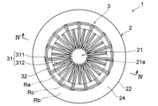
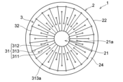
- FIG. 3 is a diagram showing one side of a fixing structure according to an embodiment of the present invention. It is a figure showing the other side of the fixed structure of one embodiment of the present invention. 3 is a schematic cross-sectional view taken along the line IV-IV in FIG. 2.
- FIG. FIG. 5 is a schematic diagram in which area A1 in FIG. 4 is enlarged.
- FIG. 5 is a schematic diagram in which area A2 in FIG. 4 is enlarged. It is an image of the cross section of the fixation structure of this embodiment which was removed together with the skin after a predetermined period of time after the fixation structure was implanted.
- FIG. 14 It is an image of a cross section of a fixed structure of a comparative example that was implanted and removed together with the skin after a predetermined period of time had elapsed. It is a schematic diagram showing the sewing pattern of the fixed structure of a 2nd embodiment. It is a schematic diagram showing the sewing pattern of the fixed structure of a 3rd embodiment. It is a schematic diagram showing the sewing pattern of the fixed structure of a 4th embodiment. It is a schematic diagram showing the sewing pattern of the fixed structure of a 5th embodiment. It is a perspective view which shows the fixation structure of 6th Embodiment before a thread-like body is sewn. 14 is a sectional view taken along the line XIV-XIV in FIG. 13. FIG.
- FIG. 16 is a schematic view showing a state in which the members of the fixing structure are assembled to each other and the filament is sewn from the state shown in FIG. 15.
- FIG. 17 is an enlarged view of a portion of the fixing structure of FIG. 16 to which the filament is sewn. It is a figure which shows the state in which the holding part was attached to the sheet body in 6th Embodiment. It is a top view which shows the 1st clamping member of the clamping part in 6th Embodiment. It is a top view of the sheet body in a 6th embodiment.
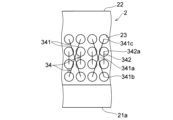
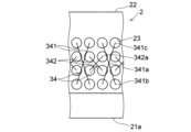
- FIG. 3 is a schematic diagram showing a simplified example of a sewing pattern in which a fixed thread-like body and a sheet body-side thread-like body are sewn. It is a schematic diagram showing the sewing pattern of the sheet body side filamentous body in the fixed structure of a 7th embodiment. It is a schematic diagram showing a modification of the fixing structure of a 7th embodiment. It is a schematic diagram showing the sewing pattern of the sheet body side filamentous body in the fixed structure of an 8th embodiment.
- perpendicular to A and similar expressions do not refer only to a direction completely perpendicular to A, but also include a direction substantially perpendicular to A. do.
- parallel to B and similar expressions do not refer only to a direction completely parallel to B, but also include a direction substantially parallel to B. do.
- C-shape and similar expressions do not refer only to a complete C-shape, but also include a shape that visually reminds one of a C-shape (approximately a C-shape).
- the fixing structure 1 of this embodiment is used when fixing the insertion member IS led out from inside the living body to the wall-like tissue T of the living body.
- the fixing structure 1 is embedded in a wall-like tissue T at a predetermined position and at a predetermined depth with the insertion member IS inserted therethrough, so that the fixation structure 1 can be inserted into the wall-like tissue T of the living body.
- Fixed to T The use of the fixing structure 1 is not particularly limited as long as it is used to fix the insertion member IS led out from the living body to the wall-like tissue T of the living body.
- the fixing structure 1 can be used for a skin button (cuff member) or the like through which the insertion member IS is inserted.
- living body refers to the body of humans and non-human animals.
- “Wall-like tissue” refers to any tissue such as a wall or membrane of a living body having a predetermined thickness, into which the insertion member IS is inserted.
- the wall-like tissue refers to various tissues in a living body, such as skin (epidermis, dermis, subcutaneous tissue), muscular layers, tissues constituting various organs, and layers in which these are combined.
- the wall-like tissue T through which the insertion member IS is inserted is a tissue that includes skin (epidermis, dermis, subcutaneous tissue) and muscle layer.
- the fixation position (buried position) in the wall-like tissue T to which the fixation structure 1 is fixed may be changed as appropriate depending on the body shape of the patient (living body) to which the fixation structure 1 is fixed.
- the fixing structure 1 connects a drive line (insertion member IS) used for a medical device (for example, an artificial organ such as an auxiliary heart (VAD) or an artificial lung) implanted in the human body to a wall of the abdomen. It is used to insert the driveline into the tissue T of the human body and lead out the driveline from inside the human body to outside the body.
- the driveline led out of the body is fixed at a predetermined position in the abdomen via a fixing structure 1, as shown in FIG.
- the insertion member IS is a linear member that has a predetermined length and is inserted into the wall-like tissue T of the living body.
- the "linear" of the insertion member IS means that the insertion member IS extends a predetermined length, regardless of whether the insertion member IS is hollow or solid.
- the insertion member IS is a medical elongated member that is placed so as to penetrate the wall-like tissue T of the living body. More specifically, the insertion member IS is a drive line for an artificial organ (artificial auxiliary heart). One end of the insertion member IS is connected to an unillustrated artificial organ placed at a predetermined position inside the body, and the other end is connected to equipment (such as a power source) placed outside the body.
- the internal structure of the insertion member IS is not particularly limited, for example, the insertion member IS includes a cooling water circulation passage that circulates cooling water between an artificial organ inside the body and a pressure pump outside the body, and a power supply between the artificial organ inside the body and a power source outside the body. It has a power cable that connects the
- the insertion member IS may be configured to include only a power cable, or may be configured to include only a cooling water circulation path.
- the insertion member IS may be configured to include a member having a function other than those described above, or may be configured as a hollow member (tube) having no internal member. When used as a hollow member that communicates between the inside and outside of the body, the insertion member IS may be used to deliver a drug from outside the body to a treatment site inside the body for treatment.
- the fixing device D shown in FIG. 1 is used to fix the insertion member IS to the wall-like tissue T while the insertion member IS is inserted through the wall-like tissue T.
- the fixing structure 1 (fixing device D) of this embodiment includes a connecting member C that (indirectly) connects the insertion member IS to the sheet body 2.
- the connection member C includes a first connection member C1 and a second connection member C2 that sandwich the sheet body 2, which will be described later, of the fixing structure 1 in the thickness direction of the sheet body 2.
- the first connecting member C1 and the second connecting member C2 are configured so that the insertion member IS can be inserted therethrough.
- the first connection member C1 and the second connection member C2 (in this embodiment, the first connection member C1) is inserted into the opening 21 of the sheet body 2.
- the portion around the opening 21 of the sheet body 2 is connected to the first connecting member C1 and the second connecting member C2. Get caught.
- the fixing structure 1 and the insertion member IS are connected via the connecting member C.
- the fixation structure 1 is embedded in the wall-like tissue T, so that the insertion member IS is inserted into the wall-like tissue T through the fixation structure 1 in a predetermined position. is fixed in position.
- connection method between the connection member C and the sheet body 2 is not limited to the connection method described above.
- the structure of the fixing structure 1 is not limited to the structure using the connecting member C shown in FIG. 2, as long as it can support the insertion member IS in the inserted state.
- the fixing structure 1 includes a cylindrical insertion part 4 and a clamping part 5, and even if the insertion part 4 and the clamping part 5 are fixed by a fixing thread-like body 33. good.
- the fixing structure 1 has an opening 21 through which an insertion member IS guided from inside the living body to outside the living body is inserted, and is made of a biocompatible non-absorbable material. It has a porous sheet body 2.
- the sheet body 2 is a portion that is embedded in the wall-like tissue T when the fixation structure 1 is fixed (fixed) to the wall-like tissue T with the insertion member IS inserted through the wall-like tissue T.
- the sheet body 2 is embedded in the wall-like tissue T so as to sneak under a part (for example, the skin) of the wall-like tissue T that is incised in order to insert the insertion member IS. Thereby, the sheet body 2 is fixed to a predetermined portion of the wall-like tissue T, as shown in FIG.
- the sheet body 2 is made of a biocompatible non-absorbable material.
- the biocompatible non-absorbable material constituting the sheet body 2 can be the same material as that used as a medical sheet inside the body or at a wound site. Further, it is preferable that the sheet body 2 is made of a flexible material before the thread-like bodies 3 described below are sewn thereon.
- materials constituting the sheet body 2 include polyurethane resins, polyamide resins, polylactic acid resins, polyolefin resins, polyester resins, fluororesins, urea resins, phenol resins, epoxy resins, polyimide resins, acrylic resins, methacrylic resins, and the like.
- the material may be at least one selected from the group consisting of derivatives of, and preferably, expanded polytetrafluoroethylene (ePTFE).
- the sheet body 2 is preferably constituted by a porous sheet in order to promote growth and settlement of the cells of the wall-like tissue T onto the sheet body 2.
- the pore diameter (average pore diameter) of the porous sheet body 2 is not particularly limited as long as it is a size that allows cells to easily grow and settle when the sheet body 2 is embedded in the wall-like tissue T.
- the average pore diameter of the sheet body 2 can be, for example, 10 to 100 ⁇ m.
- the shape of the sheet body 2 is not particularly limited as long as it is a shape that allows the insertion member IS to be inserted therethrough and is suitable for being embedded in the wall-like tissue T.
- the sheet body 2 is formed in a circular (substantially circular) shape with an opening 21 in the center, but may be formed in a shape other than circular, such as an ellipse or a polygon.
- the size of the sheet body 2 is not particularly limited, and may be changed as appropriate depending on the diameter of the insertion member IS inserted through the sheet body 2, the use of the fixing structure 1, and the fixing location.
- the sheet body 2 can have a size similar to that of a flange portion of a known skin button (cuff member) that is embedded in the wall-like tissue T, for example.
- the diameter of the sheet body 2 can be, for example, 5 to 80 mm.
- the thickness of the sheet body 2 is not particularly limited, but may be, for example, 0.5 to 5 mm.
- the longitudinal dimension of the sheet body 2 can be 10 mm to 80 mm.
- the major axis of the sheet body 2 can be 40 to 80 mm, and the minor axis can be 20 to 40 mm.
- the opening 21 provided in the sheet body 2 is provided in the central portion of the sheet body 2 so as to penetrate through the sheet body 2 in the thickness direction.
- the size of the opening 21 is appropriately set so that the insertion member IS can be inserted therethrough.
- the opening 21 is provided with a size that allows the connection member C (see FIG. 1) to be inserted therethrough (with a thread-like body described later provided therein).
- a predetermined area of the sheet body 2 is defined in a direction from the opening edge 21a of the opening 21 toward the outer peripheral edge 22 of the sheet body 2 (in the present embodiment, radially outward of the sheet body 2). It is called the central region Ra (see FIG. 2).
- a region around the outer circumferential edge 22 of the sheet body 2 that is, in a direction from the outer circumferential edge 22 of the sheet body 2 toward the opening 21 (in the present embodiment, the radially inner side of the sheet body 2).
- the predetermined region is called a peripheral region Rb (see FIG. 2).
- the region between the central region Ra and the peripheral region Rb is called an intermediate region Rc (see FIG. 2).
- the range of the central region Ra of the sheet body 2 is not particularly limited, but for example, the range from the opening edge 21a of the sheet body 2 to the distance (in the radial direction) between the opening edge 21a and the outer peripheral edge 22 of the sheet body 2.
- the range can be from 30% to 60%.
- the range of the peripheral edge region Rb of the sheet body 2 is not particularly limited, but it is the distance (in the radial direction) from the outer peripheral edge 22 of the sheet body 2 to the opening edge 21a of the sheet body 2 and the outer peripheral edge 22.
- the range can be from 20% to 60%.
- the range of the central region Ra and the intermediate region Rc is from the opening edge 21a of the sheet body 2 to 50% of the distance (in the radial direction) between the opening edge 21a of the sheet body 2 and the outer peripheral edge 22.
- the sheet body 2 has (a plurality of) through holes 23 (see FIG. 6) that pass through the sheet body 2 in the thickness direction and through which the filamentous body 3 is inserted.
- the through-hole 23 is formed at a predetermined position according to a predetermined uneven structure (by the thread-like body 3) formed on the sheet body 2 (described later) before the thread-like body 3 is sewn on. Since the through-hole 23 is provided in advance at a predetermined position on the sheet body 2 before the thread-like body 3 is sewn, the through-hole 23 serves as a mark as to where the thread-like body 3 should be sewn. , it is possible to easily form a concavo-convex structure by the thread-like bodies 3. Note that in this embodiment, four through holes 23 are provided in the radial direction and arranged side by side in the circumferential direction, but the number and arrangement of the through holes 23 may be changed as appropriate depending on the sewing pattern.
- the size of the through hole 23 through which the filamentous body 3 is inserted is not particularly limited as long as the filamentous body 3 can be inserted therethrough.
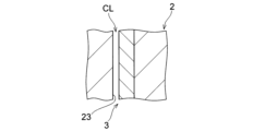
- the through hole 23 has a clearance CL (see FIG. 6) between the inner periphery of the portion of the sheet body 2 in which the through hole 23 is formed and the filament 3 of 1 mm or less, preferably 100 ⁇ m or more. It is formed to have a thickness of 300 ⁇ m. In this case, not only the gap between the filamentous body 3 and the surface of the sheet body 2, which will be described later, but also the clearance CL between the filamentous body 3 and the through hole 23 of the sheet body 2, body fluid flows toward the epidermis.
- the clearance CL is the maximum gap between the inner periphery (inner surface) of the portion of the sheet body 2 where the through hole 23 is formed and the outer periphery of the filamentous body 3 in the extending direction of the surface of the sheet body 2. be able to.
- the filamentous body 3 is inserted into one through hole 23 from one surface 2a (see FIG. 4) of the sheet body 2 to the other surface 2b (see FIG. 4), or from the other surface 2b to one surface 2a. , it may be inserted multiple times or multiple times.
- the clearance CL is defined as the difference between the inner periphery (opening edge) of the portion of the sheet body 2 where the through hole 23 is formed and the outer periphery of the filament 3 when the filament 3 is passed through the filament 3 multiple times or multiple times.
- the fixing structure 1 includes a thread-like body 3 sewn onto the surface of the sheet body 2, as shown in FIGS. 1 to 6.
- the filamentous body 3 forms a concavo-convex structure that provides resistance to relative movement of the sheet body 2 in the extending direction of the sheet body 2 with respect to the target site of the living body through which the insertion member IS is inserted.
- the target site of the living body is the peripheral portion of the wall-like tissue T through which the insertion member IS is inserted. More specifically, the target part of the living body is a part of the wall-like tissue T that is incised in order to install the fixing structure 1 through which the insertion member IS is inserted.
- the term "filamentous body” when it is possible to form a concavo-convex structure that provides resistance to relative movement with respect to the target area in the extending direction of the sheet body 2, it is possible to sew only the part of the sheet body 2.
- the present invention is not limited to the attached filament bodies (radial suture portions 31, circumferential suture portions 32, sheet body side filament bodies 34, etc., which will be described later).
- the "filamentous body” also includes a fixed filamentous body 33 that fixes the sheet body 2 and other members (for example, the holding portion 5 described below), as described later.
- the "uneven structure that provides resistance to relative movement with respect to the target area in the extending direction of the sheet body 2" constituted by the filamentous body 3 is defined by the thickness of the sheet body 2 in the direction in which the sheet body 2 extends, that is, the thickness of the sheet body 2. Relative movement between the two sheets and the target region (wall-like tissue T. Hereinafter, the target region is also referred to as wall-like tissue T) in any direction perpendicular to the direction is suppressed.
- the uneven structure is formed by sewing thread-like bodies 3 on the surface of sheet body 2 (one surface 2a and/or the other surface 2b in the thickness direction) in a predetermined pattern. It is provided by protruding from the surface in the thickness direction of the sheet body 2 (see FIGS.
- the portion where the filamentous body 3 is sewn to the sheet body 2 constitutes a convex portion with an uneven structure, and the portion where the filamentous body 3 is not provided, that is, the surface of the sheet body 2 constitutes a concave portion with an uneven structure. It consists of
- the fixing structure 1 is sewn onto the surface of the sheet body 2 so as to form an uneven structure that provides resistance to relative movement with respect to the target region in the extending direction of the sheet body 2. It has a filamentous body 3 which is attached to the filament 3. Thereby, when the fixation structure 1 is provided at the target site (wall-like tissue T), a part of the wall-like tissue T enters into the recess of the uneven structure.
- the contact area with the wall-like tissue T is larger than that of a fixing structure consisting only of a sheet body without thread-like bodies, so the uneven structure of the fixing structure 1 is The resistance when 1 moves against the wall-like tissue T also increases.
- the sheet body 2 and the wall-like tissue T move relative to each other in the extending direction of the sheet body 2 parallel to the surface of the sheet body 2 (in the present embodiment, the radial direction and the circumferential direction of the sheet body 2). Movement of the sheet body 2 relative to the wall-like tissue T or movement of the wall-like tissue T relative to the sheet body 2 is suppressed. Therefore, it is possible to suppress misalignment of the sheet body 2 relative to the target site, such as the skin, without suturing the sheet body 2 to the target site. Therefore, the fixation structure 1 can be fixed to the target site at an early stage with a simple treatment.
- the uneven structure formed by the filamentous body 3 suppresses the positional shift of the fixing structure 1 with respect to the wall-like tissue T of the living body. Therefore, the cells of the wall-like tissue T stably proliferate and enter the sheet body 2, and healing of the incision site (target site) through which the insertion member IS is inserted is promoted.
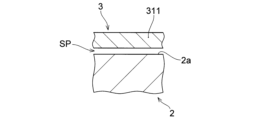
- a minute space SP ( In FIG. 5, the size of the space SP is exaggerated for ease of understanding).
- the fixed structure 1 is embedded in the wall-like tissue T and a predetermined period of time has elapsed, cells of the wall-like tissue T enter this minute space SP.
- This promotes healing of the wall-like tissue T at the incision site, and enables early fixation of the fixation structure 1 to the wall-like tissue T.
- the filamentous body 3 becomes restrained by the entering cells. Therefore, even if the entire fixed structure 1 attempts to move relative to the wall-like tissue T, the cells that have entered the minute space SP become entangled with the filament 3, and the relative movement of the fixed structure 1 to the wall-like tissue T is prevented. suppressed.
- FIG. 7 shows that after making an incision on the back of a rat and embedding the fixation structure 1, which has a filament 3 sewn to an ePTFE sheet body 2, under the skin for 30 days, the fixation structure 1 was inserted into the back including the skin.
- This is a hematoxylin and eosin stained (HE stained) image of a cross-section of the area removed from the body and enlarged 40 times.
- cells of the wall-like tissue T have entered between the filamentous bodies 3 and the sheet bodies 2, and between the filamentous bodies 3 and the filamentous bodies 3, making it difficult for the skin to peel off. It was observed that there were.
- FIG. 8 shows that the fixation structure of the comparative example was implanted under the same conditions as in FIG. 7 except that the fixation structure of the comparative example in which the filament 3 was not sewn was used. This is a hematoxylin and eosin stained (HE stained) image of the cross section of the removed portion enlarged 40 times.
- a porous ePTFE sheet similar to the image shown in FIG.
- the uneven structure may be provided on at least one surface of the sheet body 2, but in this embodiment, the uneven structure is provided on both surfaces of the sheet body 2.
- the uneven structure is provided on both surfaces of the sheet body 2
- relative movement between the fixing structure 1 and the wall-like tissue T can be further suppressed, and one surface 2a of the sheet body 2 and the other surface It becomes easier for cells of the wall-like tissue T to invade on both surfaces 2b, and healing of the incision site is further promoted.
- the filamentous body 3 is made of a biocompatible non-absorbable material.
- the biocompatible, non-absorbable material constituting the filament 3 can be the same material used as medical suture threads.
- the material constituting the filamentous body 3 include polyurethane resin, polyamide resin, polylactic acid resin, polyolefin resin, polyester resin, fluororesin, urea resin, phenol resin, epoxy resin, polyimide resin, acrylic resin, methacrylic resin, and the like.
- the material may be at least one selected from the group consisting of derivatives of, and preferably, expanded polytetrafluoroethylene (ePTFE).
- the filamentous body 3 is preferably porous in order to promote the growth and settlement of cells of the more wall-like tissue T.
- the thickness of the filamentous body 3 is not particularly limited as long as it can form a concavo-convex structure that provides resistance to relative movement with respect to the target area in the extending direction of the sheet body 2, but for example, the thickness may be 0.1 to 0.5 mm in diameter. Threads of 5 mm, preferably 0.1 to 0.3 mm, more preferably 0.2 mm can be used.
- the thread-like body 3 is sewn onto the sheet body 2 in a predetermined sewing pattern that will be described later.
- the sewing pattern of the filamentous body 3 is not particularly limited as long as it can form a concavo-convex structure that provides resistance to relative movement with respect to the target region in the extending direction of the sheet body 2.
- the entire sewing pattern of the thread-like body 3 may be sewn continuously using one thread-like body 3, or may be sewn separately using a plurality of thread-like bodies 3.
- the filament 3 may have one surface 2a and the other surface 2b sewn with the same sewing pattern, or one surface 2a and the other surface 2b may be sewn with a different sewing pattern.
- the filamentous body 3 has a plurality of radial seams 31 extending in a radial direction that connects the opening 21 and the outer peripheral edge 22 of the sheet body 2, as shown in FIGS. 2 and 3. ing. Further, the filamentous body 3 has a circumferential seam portion 32 extending in the circumferential direction of the sheet body 2 .
- the radial stitching portion 31 is a part of the stitching pattern of the filament 3 that extends radially.
- “extending radially” means that the filamentous body 3 extends in the direction connecting the opening 21 and the outer peripheral edge 22 (hereinafter referred to as the radial direction).
- the radial stitching portions 31 extend in the radial direction of the circular sheet body 2.
- the radial suture portion 31 may be inclined with respect to the radial direction of the sheet body 2 as long as it extends in the direction connecting the opening 21 and the outer peripheral edge 22 so as to radiate from the opening 21.
- the radial seam portions 31 extend radially from the opening edge 21a of the sheet body 2, but they do not necessarily need to extend from the opening edge 21a, and are located closer to the outer peripheral edge 22 than the opening edge 21a. It may extend from the position toward the outer peripheral edge 22 side (radially outward).
- the radial seam portions 31 extend in the radial direction from the opening 21 to a length that does not reach the outer peripheral edge 22, and as described later,
- the body 2 has a non-sewn portion 24 to which the filamentous body 3 is not sewn.
- the radial suture portion 31 constitutes a part of the uneven structure, and by extending radially, suppresses relative movement between the fixation structure 1 and the wall-like tissue T in a direction intersecting the radial direction.
- the radial suture portion 31 is constituted by a plurality of radial suture portions 311 and 312 extending in a plurality of radial directions at predetermined angular intervals from the opening edge 21a.
- the plurality of radial suture parts 311 and 312 are provided over the entire circumferential direction of the opening edge 21a.
- each radial suture portion 311, 312 acts as a resistance and can suppress rotation of the fixed structure 1.
- the plurality of radial suture parts 311 and 312 extending in the plurality of radial directions are provided with different lengths, but the plurality of radial suture parts extending in the plurality of radial directions are provided with the same length. It may be
- the radial suture portion 31 may have a plurality of radial suture portions 311 and 312 having different lengths.
- the radial suture section 31 includes a plurality of first radial suture sections 311 extending from the opening 21 by a predetermined length in the radial direction, as shown in FIGS. 2 and 3; It has a plurality of second radial suture parts 312 extending in the radial direction from the opening 21 with a length shorter than the length of the first radial suture part 311.
- the radial suture portion 31 has other radial suture portions (for example, a third radial suture portion, a fourth radial suture portion, etc.) that are different in length from the first radial suture portion 311 and the second radial suture portion 312. You may do so.
- some of the plurality of radial suture parts 31 may be adjacent to each other in the circumferential direction and extend in parallel to each other in one radial direction. In this case, a space is formed between the radial suture parts 31 adjacent to each other. When the cells of the wall-like tissue T enter this space, the cells that enter the space become entangled with the filamentous body 3, and the relative movement of the fixed structure 1 with respect to the wall-like tissue T is further suppressed.
- the circumferential seam portion 32 is a part of the sewing pattern of the filament 3 that extends in the circumferential direction.
- "extending in the circumferential direction” means extending in substantially the same direction as the direction along the outer peripheral edge 22 of the sheet body 2 or the opening edge 21a of the sheet body 2.
- the circumferential seam portion 32 extends in a direction intersecting the radial direction (radial direction of the sheet body 2). More specifically, the circumferential stitching section 32 connects one radial stitching section 31 (first radial stitching section 311) and another radial stitching section 31 (first radial stitching section 311) in the same radial direction. It extends so as to connect at a certain position.
- the circumferential seam 32 extends to intersect with the radial seam 31 (extends to connect the ends of the first radial seam 311 on the outer peripheral edge 22 side).
- the circumferential seam portion 32 does not necessarily need to intersect with the radial seam portion 31.
- the circumferential seam portion 32 is provided so as to be continuous in the circumferential direction and to make one revolution around the axis of the insertion member IS inserted through the opening 21.
- the circumferential seam portion 32 does not need to be provided continuously in the circumferential direction, and may be separated in the middle and provided intermittently in the circumferential direction.
- the circumferential suture portion 32 constitutes a part of the uneven structure, and by extending in the circumferential direction, prevents relative movement between the fixing structure 1 and the wall-like tissue T in a direction intersecting the circumferential direction. suppress.
- the fixing structure 1 embedded in the wall-like tissue T is suppressed from separating from the wall-like tissue T.
- the fixing structure 1 receives a force such that the central portion near the opening 21 is pulled upward. In this case, in FIG.
- the portion of the fixing structure 1 on the right side with respect to the insertion member IS receives a force to move to the left, and the portion on the left side with respect to the insertion member IS receives a force that tends to move to the right.
- the circumferential suture portion 32 acts as a resistance to this force by being hooked on the wall-like tissue T, thereby suppressing displacement of the fixing structure 1 and separation from the wall-like tissue T. Further, since the circumferential seam portion 32 extends continuously in the circumferential direction, it is possible to suppress bending of the sheet body 2 whose bending line is a direction intersecting the circumferential direction.
- the sheet body 2 does not have the filamentous body 3 sewn to the peripheral edge region Rb having a predetermined width from the outer peripheral edge 22 of the sheet body 2, as shown in FIGS. 2 and 3. It has a non-stitched part 24.
- the non-stitched section 24 is a section where neither the radial stitched section 31 nor the circumferential stitched section 32 is provided, and is a section composed only of the sheet body 2. Since the sheet body 2 has the non-sewn portion 24, the peripheral region Rb of the fixing structure 1 is in a flexible state with respect to the central region Ra. Therefore, in a state where the fixing structure 1 is embedded in the wall-like tissue T, it is possible to follow the movement of the wall-like tissue T such as the skin.
- the filamentous bodies 3 are arranged in a sheet such that the threads 3 become denser to coarser from the central region Ra side around the opening 21 of the sheet body 2 toward the outer peripheral edge 22 side (peripheral region Rb side) of the sheet body 2. Sewn onto body 2.
- the filament 3 (particularly the radial suture portion 31 in this embodiment) becomes dense in the central region Ra, thereby increasing the rigidity of the central region Ra of the fixing structure 1, and the fixing structure 1 deforms in the central region Ra. It becomes difficult. This suppresses deformation of the fixing structure 1 even if force is applied from the insertion member IS inserted into the fixing structure 1 to deform the portion around the opening 21 of the fixing structure 1 due to the weight of the inserting member IS.
- the insertion member IS inserted through the fixation structure 1 can be maintained at a predetermined angle with respect to the target site (wall-like tissue T). Therefore, cells that have grown between the fixation structure 1 and the wall-like tissue T are prevented from peeling off due to the fixation structure 1 deforming or tilting with respect to the wall-like tissue T. Therefore, cell growth is not inhibited, cell proliferation becomes active in the central region Ra, healing of the incision site is promoted, and downgrowth can be suppressed.
- the fixing structure 1 (sheet body 2) follows and conforms to the movement and shape of the target region such as the skin. Therefore, the patient who has had the fixation structure 1 implanted can feel less uncomfortable when the fixation structure 1 is implanted.
- the density becomes coarser from the central region Ra side to the outer peripheral edge 22 side of the sheet body 2 refers to the entire predetermined region of the filamentous body 3 on the central region Ra side (in FIG. 2, the central region Ra The amount per unit area in the entire area within) is larger than the amount per unit area in the entire predetermined area on the outer peripheral edge 22 side (in FIG. 2, the entire intermediate region Rc or the entire peripheral region Rb). It means.
- the density becomes coarser from the central region Ra side toward the outer peripheral edge 22 side of the sheet body 2 is a comparison between predetermined regions having a predetermined width in the radial direction, and Even if there is a part where the density of filamentous bodies 3 (the proportion occupied by filamentous bodies 3 per unit area of the fixed structure 1) increases locally toward the outside, the density is low when compared from area to area. It is fine as long as it is.
- the stitching pattern of the thread-like body 3 is not particularly limited as long as the thread-like body 3 is sewn to the sheet body 2 from the central region Ra side to the outer circumferential edge 22 side from densely to coarsely.
- the radial suture section 31 has a first radial suture section 311 and a second radial suture section 312, and the end of the first radial suture section 311 on the outer periphery side (hereinafter referred to as the outer end) is It is located outside the outer end of the second radial suture portion 312 in the radial direction. Thereby, the first radial stitching section 311 projects in the radial direction with respect to the second radial stitching section 312.
- the central region Ra where both the first radial stitching section 311 and the second radial stitching section 312 are provided is smaller than the middle region Rc where the second radial stitching section 312 is not provided.
- the density of the radial seams 31 is increased (in this embodiment, the circumferential seams 32 are provided in the intermediate region Rc, but even if the circumferential seams 32 are included, the central region Ra is not as dense as the intermediate region Rc).
- a predetermined region of the central region Ra may be sandwiched between the connecting member C or the like from the opening edge 21a of the opening 21, and in such a case, the filamentous bodies 3 may vary from dense to coarse.
- the portions that are not sandwiched by the connecting members C etc. may be from dense to coarse.
- the filamentous body 3 (particularly the radial suture portion 31) gradually becomes denser to coarser from the central region Ra side toward the outer peripheral edge 22 side.
- "Going from dense to coarse in stages” means that the filament 3 has regions with different densities of two or more stages, but preferably the filaments 3 have regions with different densities of three or more stages. It is preferable that the steps are provided in stages.
- the fixing structure 1 easily follows the movement of the target site, such as the skin, from the central region Ra to the peripheral region Rb of the sheet body 2. be able to. Therefore, the stiffness of the sheet body 2 was prevented from suddenly changing and stress was applied locally, the sheet body 2 was bent, and the surface of the sheet body 2 and the cells of the wall-like tissue T were fixed. Delay in healing of the incision site due to peeling of the part is suppressed.
- the fixing structure 1 of the second embodiment has a plurality of circumferential seams 32, as shown in FIG. Specifically, the fixing structure 1 of the second embodiment has a plurality of (three in FIG. 9) circumferential seams 32 having different distances from the opening edge 21a in the radial direction.
- the fixing structure 1 of this embodiment does not have a radial sutured portion, and has a non-stitched portion 24 that does not have a filamentous body 3 in the peripheral region Rb.
- by providing the plurality of circumferential sutures 32 by providing the plurality of circumferential sutures 32, relative movement in the radial direction between the fixing structure 1 and the wall-like tissue T is further suppressed.
- the fixing structure 1 of the third embodiment has a plurality of (three in FIG. 10) circumferential seams having different distances from the opening edge 21a in the radial direction, similarly to the second embodiment. It has 32.
- the fixing structure 1 of this embodiment has a non-stitched portion 24 that does not have the filamentous body 3 in the peripheral region Rb.
- a plurality of radial seams 31 are provided in the central region Ra and extend from a circumferential seam 32 closest to the opening 21 in the radial direction toward the opening edge 21a.
- the fixation structure 1 of the present embodiment is provided with a plurality of circumferential sutures 32, so that the fixation structure 1 and the wall-like tissue T can be fixed relative to each other in the radial direction. Movement is further restricted. Moreover, by having a plurality of radial suture parts, relative movement between the fixation structure 1 and the wall-like tissue T in a direction intersecting the radial direction can be suppressed. Moreover, since the plurality of radial suture parts 31 are provided over the entire circumferential direction of the opening edge 21a, rotation of the fixing structure 1 with respect to the wall-shaped tissue T can be suppressed.
- the central region Ra side is dense and the outer peripheral edge 22 side of the sheet body 2 is coarse, the rigidity of the central region Ra of the fixing structure 1 is increased, and the fixing structure 1 becomes difficult to deform in the central region Ra. Therefore, as described above, the insertion member IS inserted through the fixing structure 1 can be maintained at a predetermined angle with respect to the target region (wall-like tissue T). Therefore, cells that have grown between the fixation structure 1 and the wall-like tissue T are prevented from peeling off due to the fixation structure 1 deforming or tilting with respect to the wall-like tissue T. Therefore, cell growth is not inhibited, cell proliferation becomes active in the central region Ra, healing of the incision site is promoted, and downgrowth can be suppressed.
- the circumferential stitching portion 32 and the radial stitching portions 31 extending radially inward from the circumferential stitching portion 32 can be provided so as to be shifted toward the outer peripheral edge 22 in the radial direction from the portion sandwiched by the connecting members C and the like.
- the fixing structure 1 of the fourth embodiment has a plurality of different radial suture parts 31 extending from the central region Ra toward the outer peripheral edge 22 side.
- the plurality of radial suture parts 31 By having the plurality of radial suture parts 31, relative movement between the fixing structure 1 and the wall-like tissue T in a direction intersecting the radial direction can be suppressed.
- the plurality of radial suture parts 31 are provided over the entire circumferential direction of the opening edge 21a, rotation of the fixing structure 1 with respect to the wall-shaped tissue T can be suppressed.
- no circumferential seam portion is provided.
- the two-dot chain line in FIG. 11 indicates the boundary of the area of the fixed structure 1.
- the plurality of different radial suture parts 31 are sewn so that the positions of the outer ends 311a, 312a, and 313a, which are the ends on the outer peripheral edge 22 side, are at different positions.
- the positions of the outer ends 311a, 312a, and 313a of the radial suture portions 31 extending from the central region Ra toward the outer peripheral edge 22 are different from each other, so that the fixing structure 1 can be moved from the central region Ra toward the outer peripheral edge 22. It is structured so that it becomes progressively denser and coarser.
- the fixing structure 1 of the present embodiment includes a plurality of first radial seams 311, a plurality of second radial seams 312, and a portion closer to the outer peripheral edge 22 of the sheet body 2 than the first radial seams 311.
- a third radial suture portion 313 extending outward (in the radial direction) is provided. More specifically, in the first to third radial suture parts 311, 312, and 313, the outer end 312a of the second radial suture part 312 is the innermost position in the radial direction (opening 21 side), and the third radial suture part 312 is the innermost position in the radial direction (opening 21 side).
- the position of the outer end 313a of the sutured portion 313 is the outermost side in the radial direction (the outer peripheral edge 22 side), and the position of the outer end 311a of the first radial sutured portion 311 is the outermost end of the second radial sutured portion 312 in the radial direction. 312a and the outer end 312a of the third radial suture portion 313.
- the density of the radial sutures 31 is highest in the central region Ra, and the density of the radial sutures 31 gradually becomes coarser toward the outer peripheral edge 22 side. It's getting closer. More specifically, in this embodiment, as shown in FIG.
- the first to third radial suture parts 311, 312, and 313 are sewn, and the density of the radial suture part 31 is the highest.
- 2 region (first intermediate region) Rc1 a third region (second region) adjacent to the outer peripheral edge 22 side of the second region Rc1, where the third radial suture portion 313 is sewn, and which has the next highest density after the second region Rc1.
- the fixing structure 1 is configured to gradually become denser to coarser from the central region Ra side toward the outer peripheral edge 22 side. This increases the rigidity of the central region Ra of the fixed structure 1, and the fixed structure 1 becomes difficult to deform in the central region Ra. Therefore, as described above, the insertion member IS inserted through the fixing structure 1 can be maintained at a predetermined angle with respect to the target region (wall-like tissue T). Therefore, cells that have grown between the fixation structure 1 and the wall-like tissue T are prevented from peeling off due to the fixation structure 1 deforming or tilting with respect to the wall-like tissue T. Therefore, cell growth is not inhibited, cell proliferation becomes active in the central region Ra, healing of the incision site is promoted, and downgrowth can be suppressed.
- the filament 3 is stitched by a plurality of different radial stitches 31 in a stepwise manner from dense to coarse.
- the fixed structure 1 can easily follow the movement of the target site, such as the skin, from the central region Ra to the peripheral region Rb of the sheet body 2. Therefore, the stiffness of the sheet body 2 was prevented from suddenly changing and stress was applied locally, the sheet body 2 was bent, and the surface of the sheet body 2 and the cells of the wall-like tissue T were fixed. Delay in healing of the incision site due to peeling of the part is suppressed.
- the third radial suture portion 313 may extend to the opening edge 21a.
- the area around the opening 21 in the central region Ra may be sandwiched by the connecting member C (see FIG. 1), etc.
- the inner ends 311b and 312b of the first and second radial suture parts 311 and 312 are connected to the opening. 21 (for example, at the same radial position as the inner end 313b of the third radial suture portion 313).
- the fixing structure 1 of the fifth embodiment further includes a circumferential seam portion 32 compared to the fixing structure 1 of the fourth embodiment.
- a circumferential seam portion 32 compared to the fixing structure 1 of the fourth embodiment.
- the circumferential seam part 32 extends in the circumferential direction so as to connect the outer ends 313a of the plurality of third radial seam parts 313, but the position of the circumferential seam part 32 in the radial direction is , but not limited to the illustrated positions. Further, as shown in FIG. 9, a plurality of circumferential seams 32 may be provided at a plurality of different radial positions.
- the sheet body 2 gradually expands from the central region Ra around the opening 21 of the sheet body 2 toward the outer peripheral edge 22 of the sheet body 2. It may be configured to have increased flexibility. In this case, the sheet body 2 can easily follow the movement of the target area, such as the skin, from the central region Ra to the peripheral region Rb, and the rigidity of the sheet body 2 will not change suddenly and stress will be applied locally. suppressed. Therefore, problems such as the sheet body 2 being bent due to local stress and the portion where the surface of the sheet body 2 and the cells of the wall-like tissue T were fixed peeling off resulting in delayed healing are less likely to occur. .
- the configuration for gradually increasing the flexibility of the sheet body 2 from the central region Ra toward the outer peripheral edge 22 is not particularly limited;
- the flexibility of the sheet body 2 can be gradually increased from the central region Ra toward the outer peripheral edge 22 by changing the thickness or applying a coating to the sheet body 2.
- the fixing structure 1 of the sixth embodiment includes a cylindrical insertion part 4 that guides the insertion member IS, and a clamping part 5 that clamps the sheet body 2 and is fixed to the insertion part 4. This is different from the fixing structure of the first to fifth embodiments. Note that the points described below can also be applied to the fixing structures of the first to fifth embodiments and the seventh to ninth embodiments.
- FIG. 13 is a perspective view showing the fixing structure of the sixth embodiment before the filament is sewn.
- FIG. 14 is a sectional view taken along the line XIV-XIV in FIG. 13.
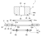
- FIG. 15 is an exploded view showing a simplified fixing structure of the sixth embodiment.
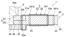
- FIG. 16 is a schematic diagram showing a state in which the members of the fixing structure are assembled to each other and the filament is sewn from the state shown in FIG. 15.
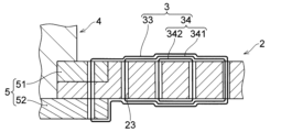
- FIG. 17 is an enlarged view of the portion of the fixing structure of FIG. 16 to which the filament is sewn. Note that FIGS. 15 to 17 conceptually simplify the fixing structure, and the number of through holes, the shape of the insertion part, etc. do not match the fixing structure shown in FIG. 14. .
- FIG. 15 to 17 conceptually simplify the fixing structure, and the number of through holes, the shape of the insertion part, etc. do not match the fixing structure shown in FIG. 14. .
- FIG. 15 to 17 conceptually simplify the fixing structure, and the number of through holes, the shape
- FIG. 18 is a diagram showing a state in which the holding portion is attached to the sheet body in the sixth embodiment.
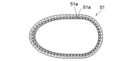
- FIG. 19 is a plan view showing the first holding member of the holding part in the sixth embodiment.
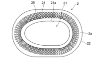
- FIG. 20 is a plan view of the sheet body in the sixth embodiment.
- FIG. 21 is a photograph showing a state in which the sheet body-side filamentous body is sewn to the sheet body in the sixth embodiment.
- FIG. 22 is a plan view showing the second holding member of the holding part in the sixth embodiment.
- FIG. 23 is a schematic view showing a simplified example of a sewing pattern in which the fixed filamentous body and the sheet body side filamentous body are sewn together.
- the fixation structure 1 of this embodiment includes a cylindrical insertion portion 4 having an insertion path 41 for guiding the insertion member IS (see FIG. 14) from inside the living body to outside the living body;
- a holding part 5 is provided which holds the opening peripheral portion of the sheet body 2 in the thickness direction of the sheet body 2 and is fixed to the insertion part 4.
- the insertion part 4 supports the insertion member IS with respect to the living body while being inserted into the insertion part 4.
- the insertion portion 4 is connected to the sheet body 2 as described later.
- the insertion part 4 is connected to the sheet body 2 via the clamping part 5.
- the insertion part 4 communicates between the inside of the living body and the outside of the living body.
- the insertion portion 4 is a portion through which an insertion member IS such as a drive line is inserted, and has a substantially cylindrical shape. As shown in FIGS. 14 to 16, the insertion portion 4 has a first opening 42 that is located inside the living body, and a second opening 43 that is located outside the living body.
- the insertion passage 41 is formed between the first opening 42 and the second opening 43.
- the shape and structure of the insertion part 4 are not particularly limited as long as the insertion part 4 can support the living body with the insertion member IS inserted into the insertion part 4.
- the insertion portion 4 is configured to protrude outside the living body.
- the insertion portion 4 is configured such that the axis of the insertion passage 41 is inclined with respect to the surface of the sheet body 2, as shown in FIG. is not particularly limited.
- the insertion passage 41 may be provided perpendicularly to the sheet body 2 (see the schematic diagram of FIG. 16, etc.).
- the insertion part 4 is arranged between the inner wall of the insertion passage 41 and the outer surface of the insertion member IS, and includes a chuck member that tightens and grips the outer peripheral surface of the insertion member IS, and the insertion part 4. 4 may include a sealing member or the like for holding the insertion member IS in a fluid-tight manner within the insertion passage 41.
- the chuck member, seal member, etc. provided between the inner wall of the insertion passage 41 and the outer surface of the insertion member IS can have a known configuration, and detailed description thereof will be omitted.
- the material forming the insertion portion 4 is biocompatible and has a predetermined rigidity.
- a metal material having biocompatibility and high corrosion resistance such as titanium or a titanium alloy, is used.
- the insertion part 4 has a mounting part 44 to which the peripheral part of the opening of the sheet body 2 and the inner peripheral part of the first holding member 51, which will be described later, are attached, as shown in FIGS. 15 to 17. are doing.
- the attachment part 44 has an engagement step part 44a that is configured to engage with a surface of the first holding member 51 opposite to the surface that contacts the sheet body 2 in the thickness direction of the sheet body 2. ing.
- the attachment part 44 is arranged such that a part of the opening periphery of the sheet body 2 and a part of the inner peripheral side of the first clamping member 51 are arranged. This is the part that The attachment portion 44 is configured such that the sheet body 2 and the first holding member 51 can be fitted onto the end portion of the insertion portion 4 where the first opening 42 is provided.
- the cylindrical portion provided with the attachment portion 44 is the cylindrical portion provided with the attachment portion 44 in the axial direction (thickness direction of the sheet body 2).
- the first cylindrical portion is configured to be one size smaller in the radial direction than the adjacent cylindrical portion (the second cylindrical portion). Due to the difference in radial size between the first cylindrical portion provided with the attachment portion 44 and the second cylindrical portion adjacent to the first cylindrical portion, the attachment portion 44 has an engagement step that is a step.
- a portion 44a is provided.
- the engagement stepped portion 44a is the surface of the first clamping member 51 that contacts the sheet body 2 when the sheet body 2 and the first clamping member 51 are attached to the insertion portion 4. It engages with the opposite surface (surface on the outside of the body) of the sheet body 2 in the thickness direction. As described later, when force is applied to the sheet body 2 from the second clamping member 52 side toward the first clamping member 51 side and the sheet body 2 is clamped, the first It engages with the holding member 51. As a result, the sheet body 2 is sandwiched under pressure and stably held against the insertion portion 4 .
- the shape and structure of the engagement step portion 44a are not particularly limited as long as the first holding member 51 and the engagement step portion 44a can engage with each other.
- the engagement step portion 44a is constituted by an annular flat portion that partially faces the surface of the first holding member 51 on the end side where the first opening portion 42 is provided.
- the length of the attachment part 44 in the thickness direction of the sheet body 2 from the engagement step part 44a to the end surface 4a of the insertion part 4 having the first opening 42 is the length of the attachment part 44 in the thickness direction of the sheet body 2. 1 and the thickness of the sheet body 2 (thickness of the sheet body 2 in the arrangement section 25 described later).
- the sheet body 2 is compressed by the first clamping member 51 and the second clamping member 52, and gaps are generated between the sheet body 2 and the first clamping member 51 and between the sheet body 2 and the second clamping member 52. is suppressed, and the sheet body 2 can be connected to the insertion portion 4 in a liquid-tight manner.
- the insertion part 4 has a fixing part 45 to which the clamping part 5 is fixed.
- the fixing part 45 is provided at the end of the insertion part 4 where the first opening 42 is provided (in this embodiment, the end surface 4a).
- the fixing means between the insertion part 4 and the clamping part 5 is not particularly limited as long as the clamping part 5 can be fixed to the insertion part 4 while the sheet body 2 is clamped by the clamping part 5.
- the fixing means between the insertion part 4 and the clamping part 5 is a fastening member SC such as a screw or a bolt, and the fixing part 45 is configured to be able to fasten the fastening member SC.
- the fixing part 45 is a screw hole provided in the end surface 4a of the insertion part 4, in which the first opening 42 is provided.
- the fastening member SC is fastened through the second clamping member 52, the second clamping member 52 moves in the direction approaching the first clamping member 51, and the sheet body 2 is compressed and clamped, and the clamping part 5 is fixed to the insertion portion 4.
- the sheet body 2 can be compressed uniformly, and a gap between the insertion part 4 and the sheet body 2 can be prevented. This makes it possible to increase the rigidity of the region of the sheet body 2 on the side of the opening edge 21a (arranging portion 25), and to prevent the sheet body 2 from coming off from the insertion portion 4.
- the holding portion 5 holds the portion around the opening of the sheet body 2 in the thickness direction of the sheet body 2. Further, as shown in FIG. 16, the holding part 5 is fixed to the insertion part 4, and indirectly fixes the sandwiched sheet body 2 to the insertion part 4.
- the holding part 5 includes a first annular holding member 51 that contacts one surface 2a of the sheet body 2 in the vicinity of the opening of the sheet body 2; An annular second holding member 52 that contacts the other surface 2b of the sheet body 2 is provided around the opening of the sheet body 2.
- the first clamping member 51 and the second clamping member 52 clamp the sheet body 2.
- One surface of the first clamping member 51 contacts and engages with the engagement stepped portion 44a of the insertion portion 4, and the other surface of the first clamping member 51 contacts one surface 2a of the sheet body 2.
- the first holding member 51 is made of a hard biocompatible material having a predetermined rigidity higher than that of the sheet body 2, and as shown in FIGS. arranged to surround the periphery.
- the material constituting the first holding member 51 is not particularly limited as long as it is biocompatible and has a predetermined rigidity higher than that of the sheet body 2.
- a metal material having biocompatibility and high corrosion resistance such as titanium or a titanium alloy
- titanium or a titanium alloy is used as the material for the first clamping member 51.
- bacteria are less likely to propagate than in the sheet body 2, and bacteria can be prevented from entering the living body along the first clamping member 51. can. More specifically, bacteria that reach the surface of the first clamping member 51 from the outer surface of the insertion portion 4 are difficult to propagate along the surface made of titanium or titanium alloy.
- the path toward the other surface 2b of the sheet body 2 is such that the mounting portion 44 and the arrangement portion 25 are shaped like steps, except for the through holes 23, 51a, etc. through which the filamentous body 3 passes.
- the intricate layout of the roads creates a detour route. Therefore, it is difficult for bacteria to propagate, and it is also difficult for bacteria to reach the other surface 2b of the sheet body 2. Therefore, healing of the incision site (target site) is promoted.
- the shape of the first clamping member 51 is not particularly limited as long as it can be attached to the insertion portion 4 and can sandwich the sheet body 2 together with the second clamping member 52.
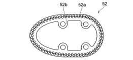
- the first holding member 51 is formed into a substantially elliptical (or substantially oval) shape with a space inside, as shown in FIGS. 13, 18, and 19. Further, the first holding member 51 is formed into a thin plate shape having one surface and the other surface. As shown in FIGS. 18 and 19, the first clamping member 51 has a plurality of through holes 51a formed in advance along the circumferential direction of the first clamping member 51 for sewing the fixed filament 33. are doing.
- the first holding member 51 is arranged in the arrangement part 25 provided around the opening of the sheet body 2, as shown in FIGS. 17 and 18.
- the arrangement portion 25 of the sheet body 2 is provided with a width corresponding to the width of the first holding member 51 in the direction connecting the opening edge 21a of the opening 21 and the outer peripheral edge 22 of the sheet body 2.
- the first holding member 51 and the opening edge 21a of the sheet body 2 are aligned, and the sheet body 2 can be attached to the attachment portion 44 of the insertion portion 4 without any gap.
- the thickness of the sheet body 2 at the placement portion 25 is configured to be thinner than the thickness of the sheet body 2 outside the placement portion 25 (on the outer peripheral edge 22 side of the sheet body 2).
- the difference between the thickness of the sheet body 2 at a portion other than the placement portion 25 and the thickness of the sheet body 2 at the placement portion 25 corresponds to the thickness of the first holding member 51.
- the second holding member 52 holds the sheet body 2 together with the first holding member 51.
- the second holding member 52 is fixed to the insertion portion 4, as shown in FIG. Thereby, the sheet body 2 sandwiched between the first clamping member 51 and the second clamping member 52 is indirectly fixed to the insertion portion 4.
- the second clamping member 52 is fastened to the insertion portion 4 so as to move in a direction approaching the first clamping member 51 in the thickness direction of the sheet body 2.
- the first clamping member 51 is compressed and clamped between the engagement step portion 44a and the second clamping member 52.
- the sheet body 2 is stably fixed to the insertion portion 4 via the first holding member 51 and the second holding member 52. Therefore, when the sheet body 2 is fixed to the target site of the living body, the insertion portion 4 is easily maintained at a predetermined angle with respect to the sheet body 2.
- the material constituting the second holding member 52 is not particularly limited as long as it is biocompatible and has a predetermined rigidity higher than that of the sheet body 2.
- a metal material having biocompatibility and high corrosion resistance such as titanium or a titanium alloy, is used as the material of the second clamping member 52.
- the shape of the second clamping member 52 is not particularly limited as long as it can be fixed to the insertion portion 4 and can sandwich the sheet body 2 together with the first clamping member 51.
- the second holding member 52 is formed into a substantially elliptical (or substantially oval) shape with a space inside, as shown in FIGS. 18 and 22. Further, the second holding member 52 is formed into a thin plate shape having one surface and the other surface. As shown in FIG. 22, the second clamping member 52 has a plurality of through holes 52a formed in advance along the circumferential direction of the second clamping member 52 for sewing the fixed filament 33. .
- the through hole 52a of the second clamping member 52 is provided at a position corresponding to the position of the through hole 51a of the first clamping member 51.
- the second holding member 52 has an insertion portion 52b into which a fastening member SC such as a screw or bolt is inserted, as shown in FIG. 22.
- the plurality of insertion portions 52b protrude inward from the annular portion of the second holding member 52.
- the second clamping member 52 is attached to the insertion part 4 by the fastening member SC inserted into the insertion part 52b. Fixed.
- the surface of the second clamping member 52 that faces the other surface 2b of the sheet body 2 presses the sheet body 2 toward the first clamping member 51, and the sheet body 2 is compressed and pressed against the clamping part 5. Retained.
- the fixing structure 1 is a fixing thread-like body sewn to the sheet body 2 so as to fix the sheet body 2 and the holding part 5. It has 33.
- the fixed thread-like body 33 is arranged so that the sheet body 2 forms an uneven structure that provides resistance to relative movement in the extending direction of the sheet body 2 with respect to the target region of the living body through which the insertion member IS is inserted. sewn onto the surface of the As described above, the fixing filament 33 forms an uneven structure that acts as a resistance to relative movement with respect to the target site, so that when the fixing structure 1 is provided at the target site (wall-like tissue T), the wall-like structure A portion of the tissue T enters the recessed portion of the uneven structure.
- the fixation structure 1 can be fixed to the target site at an early stage with a simple treatment.
- the fixing structure 1 has the sheet body side filamentous body 34 in addition to the fixed filamentous body 33, but it has only the fixed filamentous body 33 without having the sheet body side filamentous body 34. You can leave it there.
- the fixing structure 1 may have only the sheet body side filamentous body 34 without having the fixing filamentous body 33.
- the filamentous body constituting the fixed filamentous body 33 can be the same filamentous body as in the first embodiment.
- the fixing thread-like body 33 is sewn to the sheet body 2 and the clamping part 5 in order to fix the sheet body 2 and the clamping part 5.
- the outer end 33a of the fixed filament 33 is inserted into the through hole 23 of the sheet body 2 located outside the placement part 25 of the sheet body 2, and
- the inner end 33b of the thread-like body 33 is inserted into the through-hole 23 provided in the sheet body 2 and the through-holes 51a and 52a provided in the holding part 5, and the fixed thread-like body 33 is sewn to the sheet body 2. ing.
- the through hole 23 through which the fixed thread-like body 33 is inserted is sufficient as long as the fixed thread-like body 33 can be inserted therethrough, and may be formed when the fixed thread-like body 33 is sewn onto the sheet body 2 with a sewing needle, or may be formed in advance.
- Through holes 23 can be formed in the sheet body 2.
- the through hole 23 through which the fixed filament 33 is inserted may be a common through hole with the sheet body side filament 34, or may be a separate through hole, depending on the size of the filament and the size of the sheet body.
- the fixed filament 33 is sewn radially, as shown in FIGS. 17 and 23.
- the length of the fixed filament 33 in the radial direction is not particularly limited.
- the fixed filament 33 has an outer end 33a extending from the opening edge 21a of the sheet body 2 to an area up to 50% of the distance between the opening edge 21a and the outer peripheral edge 22 (for example, from 20 to 50%). 50% area).
- the fixed filament 33 is preferably sewn so as to straddle the sheet body side filament 34 sewn to the sheet body 2 (so as to overlap the sheet body side filament 34).
- a small space is also created between the fixed filamentous body 33 and the sheet body side filamentous body 34. Therefore, cells of the wall-like tissue T enter these minute spaces, promoting healing at the incision site of the wall-like tissue T, and enabling early fixation of the fixation structure 1 to the wall-like tissue T. Further, when the cells of the wall-like tissue T enter these minute spaces, the fixed filament 33 and the sheet-side filament 34 are restrained by the cells that have entered. Therefore, even if the entire fixed structure 1 attempts to move relative to the wall-like tissue T, the cells that have entered the minute space become entangled with the fixed filaments 33 and the sheet-side filaments 34, causing the wall-like tissue T of the fixed structure 1 to move. Movement relative to tissue T is suppressed.
- the fixing structure 1 further moves relative to the target region in the extending direction of the sheet body 2 on the outside of the holding part 5.
- the sheet body side filamentous body 34 is sewn onto the surface of the sheet body 2 so as to form a concavo-convex structure that provides resistance.
- the sheet body-side filamentous body 34 forms an uneven structure that provides resistance to relative movement with respect to the target region, similarly to the filamentous body 3 of the first to fifth embodiments.
- the fixation structure 1 can be fixed to the target site at an early stage with a simple treatment.
- the sheet body side filament 34 a filament similar to the filament 3 or fixed filament 33 described in the first to fifth embodiments can be used.
- the sheet body side filamentous body 34 is a filamentous body sewn only to the sheet body 2, and is not sewn to the clamping portion 5 (the first clamping member 51 and the second clamping member 52).
- the extending direction of the sheet body side filamentous body 34 is not particularly limited as long as the sheet body side filamentous body 34 can form the above-described uneven structure.
- the sheet body side filamentous bodies 34 may extend in the radial direction, may extend in the circumferential direction, or may extend at an angle with respect to the radial direction or the circumferential direction.
- the region in which the sheet body side filamentous bodies 34 extend is not particularly limited as long as the sheet body side filamentous bodies 34 can form the above-described uneven structure.
- the sheet body side filamentous body 34 is located outside the holding part 5 and extends from the opening edge 21a of the sheet body 2 to 50% of the distance between the opening edge 21a and the outer peripheral edge 22 (for example, from 20 to 50%). 50% of the area). Further, in this embodiment, the sheet body side filamentous body 34 is shown as a cross-stitched portion 341 (see FIG. 23), which will be described later.
- the sheet body side thread-like bodies 34 are not limited to the sewing pattern shown in FIG. 23, and may be the thread-like bodies 3 described in the first to fifth embodiments, or may have other sewing patterns. .
- the sheet body side filamentous bodies 34 have cross stitching portions 341 that intersect so as to overlap in the thickness direction of the sheet body 2.
- the cross suture portion 341 is a suture portion having a structure in which at least two filamentous bodies extending in different directions cross each other.
- the sheet body side filamentous body 34 has the cross stitched portion 341, one of the filamentous bodies that intersect with each other overlaps and rides on the other filamentous body. Therefore, at the intersection of the cross-stitched portions 341, the height of the uneven structure formed by the cross-stitched portions 341 increases in the direction perpendicular to the surface of the sheet body 2 (thickness direction of the sheet body 2).
- the fixing structure 1 when the fixing structure 1 is placed on the target part of the living body, the frictional force between the fixing structure 1 and the target part of the living body can be made higher, and the fixing structure 1 can be applied to the target part such as the skin. Misalignment can be further suppressed. Furthermore, a small space is created between the filamentous bodies that intersect with each other at the cross-sewn portion 341 . Therefore, the fixed structure 1 forms a more complex three-dimensional structure, which makes it easier for cells to enter and settle therein.
- the cross-stitched portion 341 is formed by two filament portions that extend from the inside of the sheet body 2 toward the outside at a slight angle with respect to the radial direction and intersect with each other. It is formed by However, as long as the cross-stitched portions 341 intersect so as to overlap in the thickness direction of the sheet body 2, the direction in which the filamentous bodies of the cross-stitched portions 341 extend is not particularly limited.
- the cross suture portion may be configured such that a filamentous body extending in the radial direction and a filamentous body extending in the circumferential direction intersect with each other in a cross shape. Further, the cross-stitched portion may be one in which three or more filament bodies intersect with each other.
- the filament bodies (fixed filament body 33, sheet body side filament body 34) are simplified and shown by lines, but in reality, the filament bodies are It has a predetermined thickness, and only a small clearance is formed between the through holes 23, 51a, 52a and the filamentous body, as explained in the first embodiment (clearance CL in FIG. 6). ).
- the method for manufacturing the fixing structure 1 in this embodiment is not particularly limited, but as an example, it can be manufactured as follows. Note that the following manufacturing method is just an example, and the manufacturing method of the fixing structure 1 is not limited, and the present invention is not limited by the following description.
- the sheet body side filamentous body 34 is sewn onto the sheet body 2 to form a sewn structure such as a cross seam portion 341 as shown in FIG. 21.
- the sheet body 2 and the first clamping member 51 are inserted from one end side of the insertion portion 4. It is arranged at the attachment part 44 of the insertion part 4.
- the second holding member 52 is arranged on the other surface 2b side of the sheet body 2 so as to follow the opening edge 21a of the sheet body 2. In this state, the second holding member 52 is fastened to the fixing part 45 of the insertion part 4 by the fastening member SC.
- the fixed thread-like body 33 is sewn to the sheet body 2, the first clamping member 51, and the second clamping member 52 over the entire circumferential direction of the sheet body 2.
- the sheet body 2 and the holding part 5 are stably fixed.
- the second holding member 52 is fixed to the insertion part 4, the sheet body 2, the holding part 5, and the insertion part 4 are fixed to each other, and the sheet body 2 is stably held relative to the insertion part 4. be done.
- the fixed thread-like body 33 may be sewn to the sheet body 2, the first clamping member 51, and the second clamping member 52 before the second clamping member 52 is fastened to the fixing part 45 of the insertion part 4. .
- the seventh embodiment differs from the sixth embodiment in that, as shown in FIG. It is similar to the form. Note that the configuration described below can be applied to other embodiments, and the configurations of other embodiments can also be applied to this embodiment.
- the sheet body side filamentous body 34 has, in addition to the cross seam portion 341, a cross seam in the direction connecting the opening edge 21a of the opening 21 and the outer peripheral edge 22 of the sheet body 2.
- An auxiliary suture provided adjacent to the cross seam portion 341 in the circumferential direction of the sheet body 2 in a region between the center portion of the seam portion 341 (a predetermined region in the radial direction including the crossing portion 341a) and the inner end 341b. 342.
- the auxiliary seam portion 342 is a seam portion auxiliary provided on the sheet body 2 so as to reinforce the uneven structure constituted by the cross seam portion 341.
- the structure of the auxiliary seam portion 342 is not particularly limited as long as it can reinforce the uneven structure constituted by the cross seam portion 341.
- the auxiliary suture portion 342 is shown as a linear suture portion that extends radially.
- the auxiliary suture portion may extend in the circumferential direction, or may extend in a zigzag shape instead of a straight line.
- the auxiliary seam portions 342 may intersect so as to overlap in the thickness direction of the sheet body 2, as shown in FIG. 25.
- the auxiliary suture portion 342 is provided in the region from the center portion of the cross suture portion 341 to the inner end 341b.
- the filamentous body can be made dense in the area between the center portion of the cross-stitched portion 341 and the inner end 341b by the cross-stitched portion 341 and the auxiliary sutured portion 342. Therefore, the rigidity of the sheet body 2 is increased in the region from the center portion of the cross-stitched portion 341 to the inner end 341b. This makes it difficult for the fixing structure 1 to deform on the inner end 341b side of the cross-sewn portion 341.
- the insertion member IS inserted through the fixing structure 1 can be maintained at a predetermined angle with respect to the target region (wall-like tissue T). Therefore, cells that have grown between the fixation structure 1 and the wall-like tissue T are prevented from peeling off due to the fixation structure 1 deforming or tilting with respect to the wall-like tissue T. Therefore, cell growth is not inhibited, and cell proliferation becomes active on the inner end 341b side of the cross suture portion 341, promoting healing of the incision site and suppressing downgrowth.
- the inner end 341b of the cross-stitched portion 341 is located at a position (for example, but not limited to
- the first holding member 51 is provided in a range within 20% of the distance between the opening edge 21a and the outer peripheral edge 22 from the outer periphery of the first holding member 51.
- the central portion (crossing portion 341a) of the cross stitching portion 341 is, for example, within 30 to 50% of the distance between the opening edge 21a and the outer peripheral edge 22 from the outer periphery of the first clamping member 51, although it is not limited thereto. set within the range.
- the rigidity of the sheet body 2 is increased in the region from the center portion of the cross-stitched portion 341 to the inner end 341b, so that the inner end 341b of the cross-stitched portion 341 of the sheet body 2 is
- the sheet body 2 becomes difficult to bend in a portion adjacent to the outer periphery of the portion 5 (first holding member 51) in the radial direction. Therefore, even if a thin and flexible sheet body 2 is used for the fixing structure 1 to the living body (flange-shaped part), the insertion portion 4 and the insertion member IS having a predetermined size and weight can be fixed at a predetermined angle. It becomes possible to support stably.
- the description "the area between the center part of the cross stitch part 341 and the inner end 341b" where the auxiliary stitch part 342 is provided refers to any area between the center part and the inner end 341b. Therefore, the auxiliary suture portion 342 may not be provided in the area corresponding to the inner end 341b of the cross suture portion 341 but may be provided only in the area corresponding to the central portion of the cross suture portion 341, or may be provided only in the area corresponding to the central portion of the cross suture portion 341. It may be provided only in the area corresponding to the inner end 341b without being provided in the area where the inner end 341b is located, or it may be provided over the entire area corresponding from the center portion to the inner end 341b.
- the outer end 342a of the auxiliary stitching section 342 is provided so as to be located inside the outer end 341c of the cross stitching section 341, as shown in FIGS. 24 and 25.
- the sheet body side filamentous body 34 provided on the sheet body 2 becomes coarse from dense to coarse from the inside to the outside due to the cross seam portion 341 and the auxiliary seam portion 342. Therefore, as described above, the sudden change in the rigidity of the sheet body 2 and the application of stress locally is suppressed, and the sheet body 2 is bent and the surface of the sheet body 2 and the cells of the wall-like tissue T are suppressed. This prevents the fixed part from peeling off and delaying the healing of the incision site.
- the eighth embodiment differs from the seventh embodiment in that the auxiliary suture section 342 is provided at a position overlapping the cross suture section 341, and the other configurations are as follows. This is the same as the seventh embodiment. Note that the configuration described below can be applied to other embodiments, and the configurations of other embodiments can also be applied to this embodiment.
- the auxiliary suture portion 342 is provided at a position overlapping the cross suture portion 341 in a region between the center portion of the cross suture portion 341 and the inner end 341b. ing.
- the cross-sewn portion 341 and the auxiliary seam portion 342 are provided to overlap, the height in the thickness direction of the sheet body 2 is increased at the portion where the filamentous body of the cross-seamed portion 341 and the filament-like body of the auxiliary suture portion 342 overlap. It gets expensive.
- the thread-like bodies of the cross-stitched portion 341 and the thread-like bodies of the auxiliary suture portion 342 intersect. Therefore, the frictional force between the fixation structure 1 and the target part of the living body is generated at the intersection of the filaments of the cross suture part 341 and the intersection of the filament of the cross suture part 341 and the filament of the auxiliary suture part 342. can be made higher. In addition, a minute space is created in the gap between the filamentous body of the cross suture part 341 and the filamentous body of the auxiliary suture part 342, forming a more complicated three-dimensional structure, which makes it easier for cells to enter and settle therein.
- auxiliary suture portion 342 “provided at a position overlapping the cross suture portion 341” refers to a portion of the filament forming the cross suture portion 341 and a portion of the filament forming the auxiliary suture portion 342. This means that they are arranged so that they intersect at some point. Therefore, the intersecting portion of the cross stitching portion 341 and the intersecting portion of the auxiliary stitching portion 342 may be misaligned. In addition, in this embodiment, as shown in FIG. 26, the intersecting part of the cross-seamed part 341 and the intersecting part of the auxiliary sewn-like part 342 overlap in the thickness direction of the sheet body 2.
- the intersecting portions of the cross suture portions 341 and the intersecting portions of the auxiliary suture portions 342 form a more complex three-dimensional structure, and cells enter this three-dimensional structure and become more likely to settle therein.
- the ninth embodiment differs from the eighth embodiment in that, as shown in FIG.
- the other configurations are the same as those of the eighth embodiment. Note that the configuration described below can be applied to other embodiments, and the configurations of other embodiments can also be applied to this embodiment.
- the auxiliary suture portion 342 is provided at a position overlapping the cross suture portion 341 in a region on the outer end 341c side of the cross suture portion 341.
- the auxiliary suture part 342 is provided on the outer end 341c side of the cross suture part 341, the area having the cross structure increases, which makes it easier for cells to infiltrate and suppresses positional displacement. be.
- the first clamping member 51 has a thickness, the difference in rigidity between the first clamping member 51 and the sheet body 2 can be further reduced.
- the auxiliary seam 342 is provided at a position overlapping the cross seam 341, but as a modification, the auxiliary seam 342 is provided in a region on the outer end 341c side of the cross seam 341, and It may be provided adjacent to the cross-stitched portion 341 in the circumferential direction of the body 2 .
- the sewing pattern of the filament may be uniform in the circumferential direction, or may be switched to different sewing patterns in the circumferential direction.
- the position of the outer end and/or inner end of the filamentous body may change in the circumferential direction.
- a porous sheet body made of a biocompatible non-absorbable material and having an opening through which an insertion member led out of the living body can be inserted; a cylindrical insertion portion having an insertion path for guiding the insertion member from inside the living body to outside the living body; a clamping part that clamps a portion around the opening of the sheet body in the thickness direction of the sheet body and is fixed to the insertion part; a fixing filament formed by a filament sewn to the sheet body so as to fix the sheet body and the holding part; The fixed filament is sewn onto the surface of the sheet body so as to form an uneven structure that provides resistance to relative movement in the extending direction of the sheet body with respect to a target region of the living body through which the insertion member is inserted. fixed structure.
- the fixing structure further includes: A sheet body side filament body is sewn onto the surface of the sheet body so as to form an uneven structure that acts as a resistance to relative movement with respect to the target area in the extending direction of the sheet body on the outside of the holding portion.
- a sheet body side filament body is sewn onto the surface of the sheet body so as to form an uneven structure that acts as a resistance to relative movement with respect to the target area in the extending direction of the sheet body on the outside of the holding portion.
- the sheet body side filament is located in the area between the central portion and the inner end of the cross seam in the direction connecting the opening edge of the opening and the outer peripheral edge of the sheet body.
- the fixing structure according to any one of (1) to (3), comprising an auxiliary suture portion provided adjacent to or overlapping the cross suture portion in the circumferential direction. .
- the sheet body side filament intersects the sheet body in the circumferential direction of the sheet body in a region on the outer end side of the cross seam in the direction connecting the opening edge of the opening and the outer peripheral edge of the sheet body.
- the fixing structure according to any one of (1) to (7), comprising an auxiliary suture portion provided adjacent to the suture portion or at a position overlapping the cross suture portion.
- the clamping portion includes a first annular clamping member that contacts one surface of the sheet body in the vicinity of the opening of the sheet body, and a first clamping member that contacts the other surface of the sheet body in the vicinity of the opening of the sheet body. a second annular holding member that contacts the surface;
- the first holding member is made of a hard biocompatible material having a predetermined rigidity higher than that of the sheet body, and is arranged to surround the insertion portion,
- the fixing structure according to any one of (1) to (9), wherein the second holding member is fixed to the insertion portion.
- the insertion part has a mounting part to which a peripheral part of the opening of the sheet body and an inner peripheral part of the first holding member are attached,
- the attachment part has an engagement stepped part configured to engage with a surface of the first holding member opposite to the surface that contacts the sheet body in the thickness direction of the sheet body,
- the second clamping member is fastened to the insertion portion so as to move in a direction approaching the first clamping member in the thickness direction of the sheet body, so that the sheet body and the first clamping member is compressed and sandwiched between the engagement step portion and the second holding member, the fixing structure according to any one of (1) to (10).
- the sheet body has an arrangement part for arranging the first holding member around the opening, and the arrangement part is arranged in a direction connecting an opening edge of the opening and an outer peripheral edge of the sheet body.
- the sheet body is provided with a width corresponding to the width of the first holding member, and the thickness of the sheet body in the placement portion is configured to be thinner than the thickness of the sheet body outside the placement portion.
- the sheet body side filamentous body is sewn to the sheet body from a central area around the opening of the sheet body toward an outer peripheral edge of the sheet body so as to become denser to coarser, (1) to The fixed structure according to any one of (12).
- the radial suture portion includes a plurality of first radial suture portions extending from the opening to a predetermined length in the radial direction, and a length shorter than the length of the first radial suture portion in the radial direction from the opening.
- the fixing structure according to any one of (1) to (15), comprising a plurality of extending second radial suture parts.
Landscapes
- Health & Medical Sciences (AREA)
- Heart & Thoracic Surgery (AREA)
- Engineering & Computer Science (AREA)
- Life Sciences & Earth Sciences (AREA)
- Hematology (AREA)
- Biomedical Technology (AREA)
- Anesthesiology (AREA)
- Animal Behavior & Ethology (AREA)
- General Health & Medical Sciences (AREA)
- Public Health (AREA)
- Veterinary Medicine (AREA)
- Cardiology (AREA)
- Pulmonology (AREA)
- Mechanical Engineering (AREA)
- Biophysics (AREA)
- Media Introduction/Drainage Providing Device (AREA)
- Surgical Instruments (AREA)
- Infusion, Injection, And Reservoir Apparatuses (AREA)
- External Artificial Organs (AREA)
Abstract
Description
以下、図面を参照し、本発明の一実施形態の固定構造を説明する。なお、以下に示す実施形態はあくまで一例であり、本発明の固定構造は、以下の実施形態に限定されるものではない。
第2実施形態の固定構造1は、図9に示されるように、複数の周方向縫合部32を有している。具体的には、第2実施形態の固定構造1は、放射方向で開口縁21aからの距離が異なる複数の(図9では3つの)周方向縫合部32を有している。本実施形態の固定構造1は、放射状縫合部を有しておらず、周縁領域Rbに糸状体3を有していない非縫合部24を有している。本実施形態では、複数の周方向縫合部32が設けられていることによって、固定構造1と壁状の組織Tとの間の放射方向での相対移動がさらに抑制される。
第3実施形態の固定構造1は、図10に示されるように、第2実施形態と同様に、放射方向で開口縁21aからの距離が異なる複数の(図10では3つの)周方向縫合部32を有している。本実施形態の固定構造1は、周縁領域Rbに糸状体3を有していない非縫合部24を有している。また、本実施形態では、中央領域Raに設けられ、最も開口21に近い周方向縫合部32から、放射方向で開口縁21aに向かって延びる複数の放射状縫合部31を有している。本実施形態の固定構造1は、第2実施形態と同様に、複数の周方向縫合部32が設けられていることによって、固定構造1と壁状の組織Tとの間の放射方向での相対移動がさらに抑制される。また、複数の放射状縫合部を有していることによって、固定構造1と、壁状の組織Tとの間の、放射方向に交差する方向の相対移動を抑制することができる。また、複数の放射状縫合部31は、開口縁21aの周方向全体に亘って設けられているので、固定構造1の壁状の組織Tに対する回転を抑制することができる。また、中央領域Ra側が密となり、シート体2の外周縁22側が粗となっているので、固定構造1の中央領域Raの剛性が高まり、固定構造1は中央領域Raにおいて変形しにくくなる。したがって、上述したように、固定構造1に挿通された挿通部材ISを対象部位(壁状の組織T)に対して所定の角度に維持することができる。したがって、固定構造1が変形したり、壁状の組織Tに対して傾いたりすることで、固定構造1と壁状の組織Tとの間で成長した細胞が剥がれてしまうことが抑制される。そのため、細胞の成長が阻害されず、中央領域Raでの細胞の繁殖が活発となり、切開部位の治癒が促進されるとともに、ダウングロースを抑制することができる。
第4実施形態の固定構造1は、図11に示されるように、中央領域Raから外周縁22側に向かって延びる複数の異なる放射状縫合部31を有している。複数の放射状縫合部31を有していることによって、固定構造1と、壁状の組織Tとの間の、放射方向に交差する方向の相対移動を抑制することができる。また、複数の放射状縫合部31は、開口縁21aの周方向全体に亘って設けられているので、固定構造1の壁状の組織Tに対する回転を抑制することができる。なお、本実施形態では、周方向縫合部は設けられていない。なお、図11における二点鎖線は、固定構造1の領域の境界を示すものである。
第5実施形態の固定構造1は、第4実施形態の固定構造1に対して、さらに周方向縫合部32を有している。第5実施形態では、第4実施形態で説明した効果に加えて、周方向縫合部32によって、固定構造1と壁状の組織Tとの間の放射方向での相対移動を抑制することができる。
第6実施形態の固定構造1は、後述するように、挿通部材ISを案内する筒状の挿通部4と、シート体2を挟持し、挿通部4に固定される挟持部5とを備えている点で、第1~第5実施形態の固定構造と異なる。なお、以下に説明する点は、第1~第5実施形態、第7~第9実施形態の固定構造にも適用することができる。
第7実施形態は、図24に示されるように、補助縫合部342が設けられている点で、第6実施形態と異なり、補助縫合部342が設けられている以外の構成は、第6実施形態と同様である。なお、以下で説明する構成は、他の実施形態においても適用することができ、他の実施形態の構成を本実施形態に適用することもできる。
第8実施形態は、図26および図27に示されるように、補助縫合部342が交差縫合部341に重なる位置に設けられている点で、第7実施形態と異なり、それ以外の構成は、第7実施形態と同様である。なお、以下で説明する構成は、他の実施形態においても適用することができ、他の実施形態の構成を本実施形態に適用することもできる。
第9実施形態では、図28に示されるように、補助縫合部342が設けられている領域が、交差縫合部341の外端341c側の領域である点で、第8実施形態と異なり、それ以外の構成は、第8実施形態と同様である。なお、以下で説明する構成は、他の実施形態においても適用することができ、他の実施形態の構成を本実施形態に適用することもできる。
前記挿通部材を生体内から生体外に案内する挿通路を有する筒状の挿通部と、
前記シート体の開口周辺部分を前記シート体の厚さ方向で挟持するとともに、前記挿通部に固定される挟持部と、
前記シート体と前記挟持部とを固定するように、前記シート体に縫い付けられた糸状体によって構成された固定糸状体と
を有し、
前記固定糸状体は、前記シート体の延在方向での、前記挿通部材が挿通される生体の対象部位に対する相対移動の抵抗となる凹凸構造を形成するように、前記シート体の表面に縫い付けられている、固定構造。
前記挟持部の外側において、前記シート体の延在方向での、前記対象部位に対する相対移動の抵抗となる凹凸構造を形成するように、前記シート体の表面に縫い付けられたシート体側糸状体を備えている、(1)に記載の固定構造。
前記第1挟持部材は、前記シート体よりも高い所定の剛性を有する硬質の生体適合性材料によって構成され、前記挿通部の周囲を取り囲むように配置され、
前記第2挟持部材は、前記挿通部に固定されている、(1)~(9)のいずれか1つに記載の固定構造。
前記取付部は、前記第1挟持部材の前記シート体と接触する面とは反対側の面と、前記シート体の厚さ方向で係合するように構成された係合段部を有し、
前記第2挟持部材が、前記挿通部に対して、前記シート体の厚さ方向で前記第1挟持部材に近付く方向に移動するように締結されることで、前記シート体および前記第1挟持部材が、前記係合段部と前記第2挟持部材との間で圧縮して挟み込まれている、(1)~(10)のいずれか1つに記載の固定構造。
2 シート体
2a シート体の一方の面
2b シート体の他方の面
21 シート体の開口
21a 開口縁
22 シート体の外周縁
23 貫通孔
24 非縫合部
25 配置部
3 糸状体
31 放射状縫合部
311 第1放射状縫合部
311a 第1放射状縫合部の外端
311b 第1放射状縫合部の内端
312 第2放射状縫合部
312a 第2放射状縫合部の外端
312b 第2放射状縫合部の内端
313 第3放射状縫合部
313a 第3放射状縫合部の外端
313b 第3放射状縫合部の内端
32 周方向縫合部
33 固定糸状体
33a 固定糸状体の外端
33b 固定糸状体の内端
34 シート体側糸状体
341 交差縫合部
341a 交差縫合部の交差部分
341b 交差縫合部の内端
341c 交差縫合部の外端
342 補助縫合部
342a 補助縫合部の外端
4 挿通部
4a 挿通部の端面
41 挿通路
42 第1開口部
43 第2開口部
44 取付部
44a 係合段部
45 固定部
5 挟持部
51 第1挟持部材
51a 貫通孔
52 第2挟持部材
52a 貫通孔
52b 挿入部
C 接続部材
C1 第1接続部材
C2 第2接続部材
CL シート体の内周と糸状体との間のクリアランス
D 固定装置
IS 挿通部材
Ra 中央領域(第1領域)
Rb 周縁領域(第4領域)
Rc 中間領域
Rc1 第1中間領域(第2領域)
Rc2 第2中間領域(第3領域)
SC 締結部材
SP 微小な空間
T 壁状の組織
Claims (12)
- 生体内から生体外に導出される挿通部材が挿通可能な開口を有し、生体親和性を有する非吸収性材料によって構成された多孔性のシート体と、
前記挿通部材を生体内から生体外に案内する挿通路を有する筒状の挿通部と、
前記シート体の開口周辺部分を前記シート体の厚さ方向で挟持するとともに、前記挿通部に固定される挟持部と、
前記シート体と前記挟持部とを固定するように、前記シート体に縫い付けられた糸状体によって構成された固定糸状体と
を有し、
前記固定糸状体は、前記シート体の延在方向での、前記挿通部材が挿通される生体の対象部位に対する相対移動の抵抗となる凹凸構造を形成するように、前記シート体の表面に縫い付けられている、固定構造。 - 前記固定構造がさらに、
前記挟持部の外側において、前記シート体の延在方向での、前記対象部位に対する相対移動の抵抗となる凹凸構造を形成するように、前記シート体の表面に縫い付けられたシート体側糸状体を備えている、請求項1に記載の固定構造。 - 前記シート体側糸状体が前記シート体の厚さ方向で重なるように交差する交差縫合部を有している、請求項1に記載の固定構造。
- 前記シート体側糸状体が、前記開口の開口縁と前記シート体の外周縁とを結ぶ方向での、前記交差縫合部の中央部分から内端までの間の領域で、前記シート体の周方向で前記交差縫合部に隣接して、または、前記交差縫合部に重なる位置に設けられた補助縫合部を備えている、請求項3に記載の固定構造。
- 前記補助縫合部の外端が、前記交差縫合部の外端に対して内側に位置するように設けられている、請求項4に記載の固定構造。
- 前記補助縫合部が、前記シート体の厚さ方向で重なるように交差している、請求項5に記載の固定構造。
- 前記交差縫合部の交差部分と、前記補助縫合部の交差部分とが、前記シート体の厚さ方向で重なっている、請求項6に記載の固定構造。
- 前記シート体側糸状体が、前記開口の開口縁と前記シート体の外周縁とを結ぶ方向での、前記交差縫合部の外端側の領域で、前記シート体の周方向で前記交差縫合部に隣接して、または、前記交差縫合部に重なる位置に設けられた補助縫合部を備えている、請求項3に記載の固定構造。
- 前記補助縫合部が、前記シート体の厚さ方向で重なるように交差している、請求項8に記載の固定構造。
- 前記挟持部が、前記シート体の開口周辺部において、前記シート体の一方の面に接触する環状の第1挟持部材と、前記シート体の開口周辺部において、前記シート体の他方の面に接触する環状の第2挟持部材とを備え、
前記第1挟持部材は、前記シート体よりも高い所定の剛性を有する硬質の生体適合性材料によって構成され、前記挿通部の周囲を取り囲むように配置され、
前記第2挟持部材は、前記挿通部に固定されている、請求項1に記載の固定構造。 - 前記挿通部は、前記シート体の開口周辺部および前記第1挟持部材の内周側の部分が取り付けられる取付部を有し、
前記取付部は、前記第1挟持部材の前記シート体と接触する面とは反対側の面と、前記シート体の厚さ方向で係合するように構成された係合段部を有し、
前記第2挟持部材が、前記挿通部に対して、前記シート体の厚さ方向で前記第1挟持部材に近付く方向に移動するように締結されることで、前記シート体および前記第1挟持部材が、前記係合段部と前記第2挟持部材との間で圧縮して挟み込まれている、請求項10に記載の固定構造。 - 前記シート体が、前記開口周辺部に前記第1挟持部材を配置するための配置部を有し、配置部は、前記開口の開口縁と前記シート体の外周縁とを結ぶ方向での前記第1挟持部材の幅に対応した幅で設けられ、前記配置部におけるシート体の厚さは、前記配置部の外側におけるシート体の厚さよりも薄くなるように構成されている、請求項10に記載の固定構造。
Priority Applications (3)
| Application Number | Priority Date | Filing Date | Title |
|---|---|---|---|
| CN202380031898.6A CN119013075A (zh) | 2022-04-28 | 2023-04-28 | 固定结构 |
| DE112023002078.7T DE112023002078T5 (de) | 2022-04-28 | 2023-04-28 | Befestigungsstruktur |
| US18/855,518 US20250235671A1 (en) | 2022-04-28 | 2023-04-28 | Fixing structure |
Applications Claiming Priority (2)
| Application Number | Priority Date | Filing Date | Title |
|---|---|---|---|
| JP2022075085A JP2023163880A (ja) | 2022-04-28 | 2022-04-28 | 固定構造 |
| JP2022-075085 | 2022-04-28 |
Publications (1)
| Publication Number | Publication Date |
|---|---|
| WO2023210795A1 true WO2023210795A1 (ja) | 2023-11-02 |
Family
ID=88518884
Family Applications (1)
| Application Number | Title | Priority Date | Filing Date |
|---|---|---|---|
| PCT/JP2023/016792 Ceased WO2023210795A1 (ja) | 2022-04-28 | 2023-04-28 | 固定構造 |
Country Status (5)
| Country | Link |
|---|---|
| US (1) | US20250235671A1 (ja) |
| JP (1) | JP2023163880A (ja) |
| CN (1) | CN119013075A (ja) |
| DE (1) | DE112023002078T5 (ja) |
| WO (1) | WO2023210795A1 (ja) |
Citations (5)
| Publication number | Priority date | Publication date | Assignee | Title |
|---|---|---|---|---|
| JPH0323868A (ja) * | 1989-06-20 | 1991-01-31 | Olympus Optical Co Ltd | 経皮端子 |
| JP2005087337A (ja) * | 2003-09-12 | 2005-04-07 | San Medical Gijutsu Kenkyusho:Kk | 医療用皮膚挿通具ホルダ及び血液ポンプシステム |
| JP2010088792A (ja) * | 2008-10-10 | 2010-04-22 | National Cardiovascular Center | カフ部材及びカフ部材ユニット |
| US20140364880A1 (en) * | 2011-09-07 | 2014-12-11 | Circulite, Inc. | Cannula tips, tissue attachment rings, and methods of delivering and using the same |
| JP2020185060A (ja) * | 2019-05-10 | 2020-11-19 | 株式会社ハイレックスコーポレーション | 保持機構組立体 |
-
2022
- 2022-04-28 JP JP2022075085A patent/JP2023163880A/ja active Pending
-
2023
- 2023-04-28 DE DE112023002078.7T patent/DE112023002078T5/de active Pending
- 2023-04-28 WO PCT/JP2023/016792 patent/WO2023210795A1/ja not_active Ceased
- 2023-04-28 US US18/855,518 patent/US20250235671A1/en active Pending
- 2023-04-28 CN CN202380031898.6A patent/CN119013075A/zh active Pending
Patent Citations (5)
| Publication number | Priority date | Publication date | Assignee | Title |
|---|---|---|---|---|
| JPH0323868A (ja) * | 1989-06-20 | 1991-01-31 | Olympus Optical Co Ltd | 経皮端子 |
| JP2005087337A (ja) * | 2003-09-12 | 2005-04-07 | San Medical Gijutsu Kenkyusho:Kk | 医療用皮膚挿通具ホルダ及び血液ポンプシステム |
| JP2010088792A (ja) * | 2008-10-10 | 2010-04-22 | National Cardiovascular Center | カフ部材及びカフ部材ユニット |
| US20140364880A1 (en) * | 2011-09-07 | 2014-12-11 | Circulite, Inc. | Cannula tips, tissue attachment rings, and methods of delivering and using the same |
| JP2020185060A (ja) * | 2019-05-10 | 2020-11-19 | 株式会社ハイレックスコーポレーション | 保持機構組立体 |
Also Published As
| Publication number | Publication date |
|---|---|
| US20250235671A1 (en) | 2025-07-24 |
| DE112023002078T5 (de) | 2025-02-13 |
| CN119013075A (zh) | 2024-11-22 |
| JP2023163880A (ja) | 2023-11-10 |
Similar Documents
| Publication | Publication Date | Title |
|---|---|---|
| AU2020203354B2 (en) | Graft anchor devices, systems and methods | |
| US6346071B1 (en) | Inflow conduit assembly for a ventricular assist device | |
| JP7014802B2 (ja) | 心臓用カニューレ | |
| US6001127A (en) | Annuloplasty ring holder | |
| US9125978B2 (en) | Cannula for heart chamber implantation and related systems and methods | |
| WO2021161884A1 (ja) | 血管吻合部の保護カバー | |
| JP6898372B2 (ja) | 尿管ステント | |
| WO2023210795A1 (ja) | 固定構造 | |
| WO2023210794A1 (ja) | 固定構造 | |
| US7758638B2 (en) | Implant with an annular base | |
| WO2025074930A1 (ja) | 固定装置 | |
| US20060004391A1 (en) | Means for connecting blood vessels (connector of blood vessels, grafts and/or prostheses) | |
| JPH11113937A (ja) | 人工血管用接続具 | |
| KR101480226B1 (ko) | 관상기관의 문합 장치 및 이를 이용한 관상기관의 문합 방법 | |
| CN218356465U (zh) | 一种法兰覆膜支架 | |
| US11389622B1 (en) | Patch for providing dialysis | |
| US9867970B2 (en) | Method of device attachment to a biological surface | |
| EP3851054A1 (en) | Occluder device | |
| ES2424975T3 (es) | Conector de vasos sanguíneos y kit con aplicador para la cirugía | |
| US20040073239A1 (en) | Blood vessel anastomosing auxiliary tool | |
| RU2245106C2 (ru) | Способ хирургического лечения релаксации диафрагмы | |
| US10335264B2 (en) | Vascular graft | |
| JP2021159093A (ja) | 医療器具および医療器具セット | |
| CA2960263A1 (en) | Vascular graft |
Legal Events
| Date | Code | Title | Description |
|---|---|---|---|
| 121 | Ep: the epo has been informed by wipo that ep was designated in this application |
Ref document number: 23796530 Country of ref document: EP Kind code of ref document: A1 |
|
| WWE | Wipo information: entry into national phase |
Ref document number: 202380031898.6 Country of ref document: CN |
|
| WWE | Wipo information: entry into national phase |
Ref document number: 18855518 Country of ref document: US |
|
| WWE | Wipo information: entry into national phase |
Ref document number: 202417086018 Country of ref document: IN |
|
| WWE | Wipo information: entry into national phase |
Ref document number: 112023002078 Country of ref document: DE |
|
| WWP | Wipo information: published in national office |
Ref document number: 112023002078 Country of ref document: DE |
|
| 122 | Ep: pct application non-entry in european phase |
Ref document number: 23796530 Country of ref document: EP Kind code of ref document: A1 |
|
| WWP | Wipo information: published in national office |
Ref document number: 18855518 Country of ref document: US |