WO2023210793A1 - Bessel beam generation device and optical scanning device using same - Google Patents
Bessel beam generation device and optical scanning device using same Download PDFInfo
- Publication number
- WO2023210793A1 WO2023210793A1 PCT/JP2023/016779 JP2023016779W WO2023210793A1 WO 2023210793 A1 WO2023210793 A1 WO 2023210793A1 JP 2023016779 W JP2023016779 W JP 2023016779W WO 2023210793 A1 WO2023210793 A1 WO 2023210793A1
- Authority
- WO
- WIPO (PCT)
- Prior art keywords
- light
- optical
- emitted
- optical axis
- section
- Prior art date
Links
- 230000003287 optical effect Effects 0.000 title claims description 104
- 238000012986 modification Methods 0.000 claims description 2
- 230000004048 modification Effects 0.000 claims description 2
- 239000013307 optical fiber Substances 0.000 abstract description 47
- 238000013461 design Methods 0.000 abstract description 6
- 230000003247 decreasing effect Effects 0.000 abstract 1
- 238000005259 measurement Methods 0.000 description 27
- 238000012014 optical coherence tomography Methods 0.000 description 17
- 238000010586 diagram Methods 0.000 description 14
- 239000000835 fiber Substances 0.000 description 12
- 238000012545 processing Methods 0.000 description 11
- 230000007423 decrease Effects 0.000 description 5
- 239000002131 composite material Substances 0.000 description 4
- 230000006870 function Effects 0.000 description 4
- 210000004204 blood vessel Anatomy 0.000 description 3
- 230000004907 flux Effects 0.000 description 3
- 239000000203 mixture Substances 0.000 description 3
- XUIMIQQOPSSXEZ-UHFFFAOYSA-N Silicon Chemical compound [Si] XUIMIQQOPSSXEZ-UHFFFAOYSA-N 0.000 description 2
- 230000000694 effects Effects 0.000 description 2
- 229910052710 silicon Inorganic materials 0.000 description 2
- 239000010703 silicon Substances 0.000 description 2
- 230000001360 synchronised effect Effects 0.000 description 2
- 241000212384 Bifora Species 0.000 description 1
- 241001465754 Metazoa Species 0.000 description 1
- 230000001133 acceleration Effects 0.000 description 1
- 230000008859 change Effects 0.000 description 1
- 238000006243 chemical reaction Methods 0.000 description 1
- 230000001427 coherent effect Effects 0.000 description 1
- 238000004891 communication Methods 0.000 description 1
- 230000008878 coupling Effects 0.000 description 1
- 238000010168 coupling process Methods 0.000 description 1
- 238000005859 coupling reaction Methods 0.000 description 1
- 230000007547 defect Effects 0.000 description 1
- 230000003111 delayed effect Effects 0.000 description 1
- 238000001514 detection method Methods 0.000 description 1
- 235000012489 doughnuts Nutrition 0.000 description 1
- 239000000284 extract Substances 0.000 description 1
- 238000003384 imaging method Methods 0.000 description 1
- 239000000463 material Substances 0.000 description 1
- 238000000034 method Methods 0.000 description 1
- 239000003973 paint Substances 0.000 description 1
- 230000000737 periodic effect Effects 0.000 description 1
- 230000010287 polarization Effects 0.000 description 1
- 230000002250 progressing effect Effects 0.000 description 1
- 239000010453 quartz Substances 0.000 description 1
- 239000000523 sample Substances 0.000 description 1
- VYPSYNLAJGMNEJ-UHFFFAOYSA-N silicon dioxide Inorganic materials O=[Si]=O VYPSYNLAJGMNEJ-UHFFFAOYSA-N 0.000 description 1
- 239000000758 substrate Substances 0.000 description 1
- 239000013598 vector Substances 0.000 description 1
Images


Classifications
-
- G—PHYSICS
- G01—MEASURING; TESTING
- G01N—INVESTIGATING OR ANALYSING MATERIALS BY DETERMINING THEIR CHEMICAL OR PHYSICAL PROPERTIES
- G01N21/00—Investigating or analysing materials by the use of optical means, i.e. using sub-millimetre waves, infrared, visible or ultraviolet light
- G01N21/17—Systems in which incident light is modified in accordance with the properties of the material investigated
-
- G—PHYSICS
- G02—OPTICS
- G02B—OPTICAL ELEMENTS, SYSTEMS OR APPARATUS
- G02B27/00—Optical systems or apparatus not provided for by any of the groups G02B1/00 - G02B26/00, G02B30/00
- G02B27/09—Beam shaping, e.g. changing the cross-sectional area, not otherwise provided for
-
- G—PHYSICS
- G02—OPTICS
- G02F—OPTICAL DEVICES OR ARRANGEMENTS FOR THE CONTROL OF LIGHT BY MODIFICATION OF THE OPTICAL PROPERTIES OF THE MEDIA OF THE ELEMENTS INVOLVED THEREIN; NON-LINEAR OPTICS; FREQUENCY-CHANGING OF LIGHT; OPTICAL LOGIC ELEMENTS; OPTICAL ANALOGUE/DIGITAL CONVERTERS
- G02F1/00—Devices or arrangements for the control of the intensity, colour, phase, polarisation or direction of light arriving from an independent light source, e.g. switching, gating or modulating; Non-linear optics
- G02F1/01—Devices or arrangements for the control of the intensity, colour, phase, polarisation or direction of light arriving from an independent light source, e.g. switching, gating or modulating; Non-linear optics for the control of the intensity, phase, polarisation or colour
Definitions
- the present invention can be suitably applied to, for example, a Bessel beam generator having a large depth of focus and an optical scanning device using the same.
- an OCT (Optical Coherence Tomography) device that generates a Bessel beam using an axicon lens is known (for example, see Patent Document 1).
- the present invention was made to solve such problems, and its purpose is to provide a Bessel beam generator and an optical scanning device using the same, which can improve the degree of freedom in design.
- the Bessel beam generator of the present invention has the following features: Light radiators from which light is emitted from the tip of the optical waveguide are arranged at equal intervals on the same circle, and the optical axis of the emitted light from each of the light radiators maintains the same angle with respect to the diametrical direction of the circle. a group of at least four light emitters arranged in a state of an input section that splits the laser light emitted from one light source and makes the split light enter each of the optical waveguides; It is characterized by having an optical waveguide section having a function of making the phase and amplitude of the emitted light the same in each of the light emitting sections.
- the optical scanning device of the present invention includes: Light radiators from which light is emitted from the tip of the optical waveguide are arranged at equal intervals on the same circle, and the optical axis of the emitted light from each of the light radiators maintains the same angle with respect to the diametrical direction of the circle.
- a group of at least four light emitters arranged in a state of an input section that splits the laser light emitted from one light source and makes the split light enter each of the optical waveguides; an optical waveguide having a function of making the phase and amplitude of the emitted light the same in each of the light emitting parts; a light receiving part that receives return light from which the emitted light is reflected and converts it into an electric signal; and an analysis section that calculates the position of a reflection point of the object to be measured by analyzing the electrical signal.
- the Bessel beam generator of the present invention includes: a rotationally symmetrical conical reflecting mirror whose generating line is a straight line or a curve with respect to the optical axis, which reflects the incident laser beam outward from the optical axis;
- the present invention is characterized by comprising a reflection cover portion disposed to cover the conical reflection mirror and re-reflecting waves reflected by the conical reflection mirror with an ellipsoidal primary mirror having the optical axis as an axis of rotational symmetry.
- the optical scanning device of the present invention includes a light source that emits a laser beam; a reflective lens into which the laser beam is incident and which reflects the laser beam outward from the optical axis; a reflective cover part that is arranged to cover the reflective lens and that irradiates the disc irradiation light by reflecting the laser light traveling outward toward the inside; and a reflective cover part that receives the returned light from which the disc irradiation light is reflected; a light receiving section that converts the signal into an electrical signal; and an analysis section that calculates the position of a reflection point of the object to be measured by analyzing the electrical signal.
- the present invention can realize a Bessel beam generating device that can improve the degree of freedom in design and an optical scanning device using the same.
- FIG. 1 is a schematic diagram showing a configuration (1) of a Bessel beam generator in a first embodiment
- FIG. It is a schematic diagram showing composition (2) of the Bessel beam generation device in a 1st embodiment.
- FIG. 2 is a schematic diagram for explaining laser light emitted from an optical fiber.
- FIG. 3 is a schematic diagram showing the configuration (3) of the Bessel beam generator in the first embodiment.
- FIG. 2 is a schematic diagram for explaining focusing (1) of the Bessel beam generator in the first embodiment.
- FIG. 3 is a schematic diagram illustrating movement of the focal point of the Bessel beam generator in the first embodiment in a plane direction.
- FIG. 2 is a schematic diagram for explaining focusing (2) of the Bessel beam generator in the first embodiment.
- FIG. 2 is a schematic diagram illustrating movement of the focal point of the Bessel beam generator in the depth direction in the first embodiment.
- FIG. 1 is a schematic diagram showing the configuration of an OCT apparatus in a first embodiment.
- FIG. 3 is a schematic diagram showing the configuration of a measuring section in the first embodiment.
- FIG. 2 is a schematic diagram showing the configuration of a Bessel beam generator in a second embodiment.
- FIG. 2 is a schematic diagram showing the configuration of an OCT apparatus in a second embodiment.
- FIG. 7 is a schematic diagram showing the configuration of a Bessel beam generator in a third embodiment. It is a schematic diagram showing the composition of the modification of the Bessel beam generation device in a 3rd embodiment.
- FIG. 1 ⁇ Configuration of disk-shaped Bessel beam generator> 10 in FIG. 1 indicates a disc-shaped Bessel beam generator.
- the fiber tip 15A inputs the divided beams to the optical fibers 15 arranged on the same circumference, and the fiber tip 15A enters the split beam into the center part of the circle.
- An irradiation beam having a donut-shaped cross-section with a missing portion is emitted as a disc-shaped Bessel beam.
- the number of beams be 8 or more, or even 16 or more.
- the laser light emitted from the light source is a laser light source that emits laser light.
- the wavelength of the laser beam is not limited and is appropriately selected depending on the object to be irradiated. For example, when the object to be irradiated is a human body, near-infrared rays (780 nm to 2500 nm) are preferably used.
- the input section 14 is provided to adjust the beam diameter of the split beam and efficiently input the beam into the optical fiber 15, and includes, for example, a coupling lens, a ball lens, a rod lens, etc. alone or in combination as appropriate.
- the optical fiber 15 emits split beams from its tip, which is the fiber tip 15A.
- the fiber tips 15A are arranged at equal intervals on one circle (indicated by a broken line).
- the split beam incident on the optical fiber 15 is emitted from the fiber tip 15A as an irradiation beam consisting of diverging light having a divergence angle ⁇ corresponding to the refractive index of the optical fiber.
- the fiber tip 15A is arranged perpendicularly to the diameter of the circle, but it may also be arranged, for example, inward (at an angle greater than 90° with respect to the diameter of the circle). good.
- This inclination angle (the angle between the diameter direction of the circle and the optical fiber 15 when viewed from the inside of the circle) is set to be the same for the 32 optical fibers 15.
- a lens 16 is attached to the tip of the fiber tip 15A.
- the lens 16 adjusts the traveling direction and divergence angle of the irradiation beam. Specifically, the divergence angle in the diameter direction of the circle is adjusted according to the depth of focus; when the depth of focus is desired to be large, the divergence angle is set to be large, and when the depth of focus is desired to be small, the divergence angle is set to be small.
- the traveling direction of each irradiation beam is set according to the focal length; when the focal length is small, the angle of inclination with respect to the diameter direction of the circle is small, and when the focal length is large, the angle of inclination with respect to the diameter direction of the circle is large.
- the divergence angle of the irradiation beam is adjusted by the shape of the entrance surface, the exit surface, or the combination of the entrance surface and the exit surface.
- a convex lens with a convex exit surface is preferably used, and when it is desired to decrease the NA, a concave lens with a concave exit surface is preferably used.
- the lens 16 also adjusts the polarization direction of the irradiation beam as necessary.
- the lens 16 may be a single lens, or may be a combination of two or more lenses.
- the 32 irradiation beams overlap and are combined, and proceed toward the center of the circle while diverging (circumference (progressing at right angles to the target) becomes one donut-shaped disk irradiation beam.
- a voltage application section 21 that applies a voltage before the tip of the optical fiber 15.
- the wavelength of the part to which the voltage is applied can be temporarily changed, and the wavefront can be accelerated or delayed.
- a voltage is applied to half of the optical fibers 15 so that the voltage applying unit 21 provided on the optical fiber 15 located in the direction in which the focus is to be shifted has the highest voltage, and gradually decreases as it moves away from the optical fiber 15. .
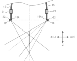
- FIG. 6 shows a state in which the focal point position has moved to the right side of the paper by delaying the wavefront on the right side in the X direction (indicated as X(R) in the figure). That is, when shifting the focal point position to the right in the X direction, a voltage is applied to the right side in the X direction (14A-1 to 14A-17). Specifically, the largest voltage is applied to 14A-9 located on the rightmost side, and the voltage decreases toward the left side.
- a lens driving section 22 can also be provided. As shown in FIG. 8, the lens driving section 22 displaces the lens 16 so as to change the angle of incidence of the lens 16 with respect to the fiber tip 15A. Thereby, the focal position with respect to the Z direction, which is the traveling direction of the disk irradiation beam, can be displaced.
- the external device 2 and the measuring section 4 are connected by a line 36.
- the line 36 There is no limit to the line 36, and any known wired line capable of electrical communication can be used. Also, a wireless network may be used instead of the line 36.
- the external device 2 is configured such that a control unit 31 consisting of an MPU (Micro Processing Unit), a ROM (Read Only Memory), and a RAM (Random Access Memory) (not shown) controls the entire external device 2 in an integrated manner. There is.
- a control unit 31 consisting of an MPU (Micro Processing Unit), a ROM (Read Only Memory), and a RAM (Random Access Memory) (not shown) controls the entire external device 2 in an integrated manner. There is.
- the control unit 31 controls the display unit 33 and the measurement unit 4 according to the user's operation input, and displays the measurement results obtained by the measurement unit 4 on the display unit 33.
- the control unit 31 starts measurement processing and connects the external interface 34 (indicated as external I/F in the figure) and the line 36.
- a start signal is supplied to the measuring section 4 via the measuring section 4.
- the measuring section 4 has the measuring section 4 inside a housing 35 whose bottom side is exposed, and a start signal is supplied to the measuring section 4.
- the measurement section 4 is configured such that a control section 19 composed of an MPU, ROM, and RAM (not shown) controls the entire measurement section 4 in an integrated manner.
- the control unit 19 When supplied with the start signal, the control unit 19 causes a light source (not shown) included in the light generation unit 11 to emit a laser beam.
- the light generator 11 converts the laser beam emitted as continuous light into frequency-modulated pulsed light using an optical comb, and emits the pulsed light.
- the light generating section 11 may perform phase modulation, frequency conversion, etc. as necessary.
- the optical path length of the light generating unit 11 is changed so that the optical path length is approximately the same as the return light of the measurement light beam irradiated onto the measurement target (as long as it is within the range of the focal point).
- a light reception signal based on the reference light beam is supplied to the signal processing section 41 .
- the laser beam emitted from the light generating section 11 is converted into parallel light by the collimating section 12, and then enters the beam splitting section 13.
- the beam splitter 13 splits the parallel light into 32 split beams having the same optical path length.
- the beam splitter 13 is an optical waveguide that enables optical wiring on a silicon or quartz substrate, such as an arrayed-waveguide grating (AWG), or a combination of multiple optical elements (for example, a combination of multiple beam splitters). or a combination of a plurality of couplers (isolators), etc.
- AMG arrayed-waveguide grating
- a combination of multiple optical elements for example, a combination of multiple beam splitters.
- a plurality of couplers isolationrs
- a reflective element for adjusting the optical path length is used as appropriate.
- the split beams are incident on the disc-shaped Bessel beam generator 10 via the optical splitter 17.
- 32 optical branching sections 17 may be provided for each of the 32 divided beams, or may be provided for each of a plurality of divided beams or for all of the divided beams.
- an optical element such as a half mirror type non-polarizing beam splitter, a polarizing beam splitter, or an isolator is used that allows one of the output light beam and the returned light beam to travel straight and changes the direction of the other.
- a quarter wavelength plate is installed between the optical branching section 17 and the lens 16.
- the disk-shaped Bessel beam generator 10 irradiates a measurement target with a disk-shaped Bessel beam as a disk irradiation beam.
- the disc-shaped Bessel beam generator 10 inputs the return light beam from the measurement target into the optical branching section 17.
- the light branching section 17 makes the returned light beam enter the light receiving section 18 .
- the light receiving section 18 generates a measurement signal, which is an electrical signal, according to the received reference light beam and the returned light beam, and supplies it to the signal processing section 41 . Further, the signal processing section 41 is supplied with a reference signal generated from the optical comb in the light generating section 11 . This reference signal is supplied at a timing synchronized with the electrical signal generated from the return light beam from the irradiation target. The signal processing section 41 generates a measurement composite signal by combining the measurement signal and the reference signal, and supplies it to the control section 19 .
- the control unit 19 supplies the measurement composite signal to the external device 2 via the external interface 23.
- the control unit 31 of the external device 2 analyzes the measurement composite signal, calculates the position of the reflection point on the measurement target, and generates image data. , is displayed on the display section 33.
- the disc-shaped Bessel beam generator 110 in FIG. 11 indicates a disk-shaped Bessel beam generator.
- the disc-shaped Bessel beam generator 110 reflects the laser light incident as diverging light outward, and then reflects the laser light from the outside inward, thereby producing an irradiation beam having a donut-shaped cross-section. It is designed to emit light.
- the incident section 115 emits a laser beam and makes it incident on the lens 116.
- the incident part 115 is, for example, a light source, an optical fiber, or another optical element, and refers to an element or component disposed in front of the lens 116.
- the lens 116 adjusts the divergence angle of the laser light and makes the laser light enter the reflective cover section 126 provided adjacently.
- the reflective cover portion 126 has a shape in which a part of a spherical or elliptical sphere is cut out, for example, and a reflective film is formed on the entire surface other than the portion where it contacts the lens 116 .
- the traveling direction of the optical axis when the laser beam is incident on the reflective cover part 126 will be referred to as the traveling direction ZP of the laser beam, and the returning direction will be referred to as the returning direction ZB.
- the reflective cover part 126 has an inner surface cut out from a part of a sphere, an elliptical sphere, or a parabolic curved surface (multidimensional function curved surface), and allows the incident laser light to pass through as it is, and directs the incident laser light to the reflective lens 125. irradiate.
- the reflective lens 125 has a pointed shape, and has a circular cross section (for example, a conical shape) in the XY direction.
- a reflective film is formed on the laser beam incident side of the reflective lens 125.
- the reflective lens 125 reflects the incident laser beam outward (preferably at an angle of 80° to 170° with respect to the traveling direction ZP of the laser beam).
- the reflective cover portion 126 reflects the laser beam inward.
- the laser beam becomes an inward irradiation beam due to the outward reflection by the reflective lens 125 and the inward reflection by the reflective cover part 126, but at this time, before entering the reflective lens 125, it is near the optical axis.
- the light located on the outside is reversed to the outside, and the light located on the outside is reversed to the inside before entering the reflective lens 125.
- the OCT device 101 includes an external device 102, an input section 115 that is an optical fiber, and a disk-shaped Bessel beam generator 110.
- the disc-shaped Bessel beam generator 110 is attached to the tip of an input section 115 that is an optical fiber.
- the external device 102 is configured such that a control unit 131 composed of an MPU, ROM, and RAM (not shown) controls the entire external device 102 in an integrated manner.
- a control unit 131 composed of an MPU, ROM, and RAM (not shown) controls the entire external device 102 in an integrated manner.
- the external device 102 includes a light generation section 111, a light branching section 117, an incident section 114, a light receiving section 118, and a signal disposed in the measurement section 4 in the first embodiment. It has a processing section 119.
- the tip portion (measuring device 104) can be made smaller (for example, about 1 mm square), and it is possible to image the inside of a blood vessel. It can be used for applications such as catheters.
- the light generating section 111 splits the pulsed light modulated by the optical comb, and supplies it to the light receiving section 118 as a reference light beam with the optical path length adjusted.
- the light receiving section 118 receives the return light beam and the reference light beam, respectively, and supplies them to the signal processing section 119 as a measurement signal and a reference signal.
- the Bessel beam generating device (disc-shaped Bessel beam generating device 10) of the present invention has the following features: At least four or more optical fiber tips (fiber tips 15A) are arranged at equal intervals on the same circle, and each optical fiber tip is arranged at the same angle with respect to the diameter direction of the circle.
- An optical fiber group (32 optical fibers 15) consisting of optical fibers (optical fibers 15), an input section (input section 14) that inputs a divided beam obtained by dividing a laser beam emitted from one light source into each of the optical fibers;
- an input section (input section 14) that inputs a divided beam obtained by dividing a laser beam emitted from one light source into each of the optical fibers;
- a lens (lens 16) that emits the disc irradiation beam.
- the Bessel beam generating device of the present invention can generate a donut-shaped Bessel beam with a free radius and divergence angle without substantially reducing the amount of light, so the focal length and depth of focus can be freely set.
- the attenuation can be covered by a large amount of light, so that the irradiation beam can reach a deep position from the surface of the material to be irradiated.
- the lens is The irradiation beam is irradiated such that the divergence angles of the irradiation beam are different in the circumferential direction of the circle and in the diametrical direction of the circle.
- the distance between adjacent optical fibers i.e., the radius of the circle
- the degree of freedom in design can be improved.
- the tip of the optical fiber is It is characterized in that it is arranged so as to be inclined inward with respect to the diametrical direction of the circle.
- the focal length can be determined by the inclination angle of the optical fiber tip, and then only the divergence angle needs to be adjusted, increasing the degree of freedom in designing the lens from which the irradiation beam is emitted. .
- Each of the optical fibers is characterized in that a voltage application device (voltage application unit 21) for temporally shifting the wavefront of the irradiation beam is attached.
- the focal position of the disk irradiation beam can be moved in a direction perpendicular to the optical axis of the disk irradiation beam.
- Bessel beam generator It is characterized by having a movable part (lens driving part 22) that rotatably operates the lens.
- the focal position of the disk irradiation beam can be moved in the optical axis direction of the disk irradiation beam.
- a light source that emits a laser beam (light source of the light generating section 11); a beam splitting unit (beam splitting unit 13) that generates split beams in which laser light emitted from one light source is split;
- beam splitting unit 13 At least four optical fiber tips are arranged at equal intervals on the same circle, and each optical fiber tip (fiber tip 15A) is arranged at the same angle with respect to the diameter direction of the circle.
- An optical fiber group (32 optical fibers 15) consisting of optical fibers (optical fibers 15), an input section (input section 14) that inputs the split beam to each of the optical fibers;
- the apparatus includes an analysis section (control section 31) that calculates the position of the reflection point of the object to be measured by analyzing the electrical signal.
- the optical scanning device can set a large focal length and depth of focus, allowing it to scan deeper positions from the surface, and even cover a wide range of irradiation targets in the optical axis direction without moving the focal point. You can check the shape etc.
- a reflective lens that reflects the incident laser beam outward from the optical axis; It is characterized by having a reflective cover part (reflective cover part 126) arranged so as to cover the reflective lens and to reflect the laser light traveling outward toward the inside.
- the Bessel beam generator can generate a donut-shaped Bessel beam with a free radius and divergence angle without almost reducing the amount of light by expanding the laser beam and then reflecting it inward. This allows you to freely set the focal length and depth of focus.
- the reflective lens is The laser beam is characterized in that the laser beam is reflected so as to travel outside the beam of the incident laser beam.
- the laser light reflected by the reflective lens does not mix with the returning light beam, and the decrease in the light amount can be minimized, and the noise mixed in the returning light beam can be minimized. It can be reduced as much as possible.
- the reflective lens is characterized in that it has a conical shape with an apex angle of 90°.
- the Bessel beam generator can bend the optical axis of the disk irradiation beam by a minimum of 90 degrees, and the laser beam is reflected in the direction in which the optical axis of the disk irradiation beam returns (opposite to the direction of travel). You can prevent this from happening. Moreover, by having a conical shape, all of the laser light can be completely converted into a disk irradiation beam.
- a light source that emits a laser beam (a light source in the light generating section 111); a reflective lens (reflective lens 125) into which the laser beam is incident and which reflects the laser beam outward from the optical axis; a reflective cover part (reflective cover part 126) arranged to cover the reflective lens and reflect the laser light traveling outward toward the inside; It is characterized by having a light receiving section (light receiving section 118) that converts the electric signal into a signal, and an analyzing section (control section 131) that calculates the position of the reflection point of the object to be measured by analyzing the electric signal.
- OCT device optical scanning device
- the optical scanning device can use a disc irradiation beam that can reach a long distance regardless of attenuation, so it can scan deep locations, such as inside blood vessels or the inside of the human body. It is also possible to observe measurement targets that could not be observed with conventional OCT devices.
- FIGS. 13 to 14 The configuration of the disk-shaped Bessel beam generator 210 is different from the second embodiment described above. Note that in the third embodiment, description of the same parts as in the second embodiment will be omitted.
- the disk-shaped Bessel beam generator 210 emits a laser beam emitted from a Cassegrain antenna-type and directional minute light source 230 by conical sub-reflection with the optical axis 235 of the laser beam as the axis. It is reflected by the conical generatrix 232 of the mirror 231.
- This conical sub-reflector 231 has a ring-shaped virtual image light source formed as an extension of the laser beam reflected toward the elliptical main reflector 233 at the first focal point of the ellipse.
- the laser beam reflected by the ellipsoidal main reflecting mirror 233 is collected in a ring shape at a second focal point 234 of the ellipsoidal surface of the ellipsoidal main reflecting mirror. It can also be constructed by forming a ring-shaped directional light source on the long axis of the ellipse at the second focal point 234 to generate a modified Bessel beam. That is, the ellipsoidal main reflecting mirror 233, the minute light source 230, and the conical sub-reflecting mirror 231 are arranged so that the first focal point and the second focal point 234 of the ellipsoidal main reflecting mirror 233 become a virtual image light source and a directional light source, respectively. It is configured.
- the position of the virtual image light source that is, the position of the first focal point of the ellipse
- the design of the ellipsoidal main reflector 231 The degree of freedom increases, and as a result, the effective range of the Bessel beam can be changed.
- the laser beam from the main reflecting mirror 240 will be parallel.
- a Bessel beam that is similar to a Bessel beam produced by an axicon lens is generated, such as a light ray, a diverging ray that spreads out a little, or a ray that focuses further away than the range of the effective Bessel beam. Note that in FIG. 14, locations corresponding to those in FIG. 13 are marked with an X.
- the modified Bessel beam generator (disc-shaped Bessel beam generator 210) of the present invention
- Light radiators from which light is emitted from the tip of the optical waveguide are arranged at equal intervals on the same circle, and the optical axis of the emitted light from each of the light radiators maintains the same angle with respect to the diametrical direction of the circle.
- a group of at least four light emitters 32 optical fibers 15 arranged in a state of an input section (input section 14) that divides a laser beam emitted from one light source and makes the divided beams enter each of the optical waveguides; It is characterized by having an optical waveguide section (lens 16) having a function of making the phase and amplitude of the emitted light the same in each of the light emitting sections.
- each of the light radiators has an optical axis adjustment lens on the front surface thereof for adjusting the angle formed between the optical axis of the emitted light, the diameter direction of the first circle, and the optical axis. do.
- each of the optical waveguides includes: It is characterized by being equipped with a phase/amplitude adjustment device for changing the wavefront of the emitted light spatially or temporally.
- the modified Bessel beam generator includes a rotationally symmetrical conical reflector whose generatrix is a straight line or a curve with respect to the optical axis and which reflects the incident laser beam outward from the optical axis;
- the present invention is characterized in that it includes a reflection cover portion that is arranged to cover the conical reflection mirror and re-reflects waves reflected by the conical reflection mirror with an ellipsoidal primary mirror having the optical axis as an axis of rotational symmetry.
- the reflective cover part is The reflected wave is re-reflected by a parabolic primary mirror having an optical axis as an axis of rotational symmetry.
- noise can be reduced by frequency modulating the laser beam by converting it into a PN code (Pseudo random Noise: pseudo random signal) such as an M sequence code. It is possible to improve the resolution of measurements.
- a light source generates coherent continuous light, converts the continuous light into a periodic light pulse train with low interference between adjacent waveforms, and converts the light pulse train into a deep observation target region of the measurement object.
- An optical pulse train whose spatial length is smaller than the pulse width range, which is biphasically phase modulated with a code (PN code such as M sequence) having autocorrelation characteristics, and the frequency of one of the optical pulse trains that is split into two is divided into two.
- a measurement optical system that irradiates one of the converted and split light pulse trains into two, and a reference optical system that changes the optical path length of the other of the two split light pulse trains to be the same as that of the measurement optical system.
- a light detection unit that receives the optical pulse train output from the reference optical system and the return light input from the measurement optical system;
- a filter extracts a difference signal having a shift frequency of the frequency shifter of the scattered wave, and a demodulator synthesizes and demodulates the difference signal extracted by the filter and a reference signal synchronized with the shift frequency of the frequency shifter,
- the signal output from the demodulator is analyzed by an analysis section to calculate the position of the reflection point of the object to be measured.
- the detailed configuration is described in WO2019/017392.
- the beam splitting section 13 is composed of an arrayed waveguide grating or the like, but the present invention is not limited to this.
- a donut-shaped beam is formed using an inverted axicon lens that has an overall conical concave portion and a slanted slope (that is, fits into a conideal shape that tapers toward the apex).
- the light may be input into the optical fiber 15 arranged in a donut shape. That is, the light beam is split upon entering the optical fiber 15.
- the inverted axicon lens plays the role of the beam splitting section 13 and the incidence section 14.
- the disc-shaped Bessel beam generator 110 is attached to the tip of the optical fiber 105, but the present invention is not limited to this.
- the light source and the light receiving section can be attached together with the disc-shaped Bessel beam generating device 110 as a tip device, and electrical signals can be exchanged between the external devices.
- the disk-shaped Bessel beam generator is equipped with a moving distance measuring device such as an acceleration sensor that can measure the moving distance, and a position specifying device that can specify the position of the disk-shaped Bessel beam generating device. It can also be added. Thereby, the position of the disc-shaped Bessel beam generator can be accurately specified, and the accuracy of image processing can be improved. In addition, if these devices are not available, it is possible to synthesize images obtained when the disk-shaped Bessel beam generator is scanned by identifying the same location in image processing or calculating motion vectors. .
- the present invention is not limited to this.
- the disk-shaped Bessel beam generator as an optical integrated circuit, and use various waveguides such as silicon photonics as the optical waveguide.
- a disc-shaped Bessel beam generator uses a conical sub-reflector whose axis is the optical axis of the laser beam to emit a laser beam emitted from a Cassegrain antenna-type, directional minute light source, around the sub-reflector.
- a ring-shaped virtual image light source is created, the light from the virtual image light source is reflected by a spheroidal main reflecting mirror, and the light is collected in a ring shape at a real focal point formed on the long axis of the ellipsoid.
- a directional light source is formed and can also be constructed by generating a modified Bessel beam.
- the laser beam radiated from the Cassegrain antenna type and directional minute light source is reflected by the conical sub-reflector whose axis is the optical axis of the laser beam.
- a ring-shaped virtual image light source is created around the mirror, and the light from the virtual image light source is reflected by a rotating paraboloid main reflecting mirror, so that the apex angle generated from the ring-shaped virtual image light source is an obtuse angle close to 180 degrees.
- the Bessel beam can be constructed by generating a conical wavefront having the following characteristics, and phase-combining these conical wavefronts on the optical axis to generate a Bessel beam.
- the light at the periphery of the light emitted from the fiber (strong at the center and weak at the periphery) connects to the nearest Bessel beam.
- the strong light in the center creates a distant beam. This cancels out the amount of light attenuation in human body tissue, and can be suitably used in the human body (for example, a catheter for measuring inside a blood vessel).
- the present invention can be used, for example, in a medical OCT device for detecting defects such as paint scratches and for observing the inside of a human or animal body.
Abstract
[Problem] To make it possible to improve the degree of freedom of design. [Solution] The present invention divides laser light emitted from one light source, and causes donut-shaped divergent light to be emitted toward the inside from optical fibers disposed on the same circle, thereby making it possible to realize a Bessel beam generation device that emits a disk irradiation beam focused in the vicinity of the center. The foregoing allows a disk irradiation beam to be generated without a center portion where the amount of light is high, and without decreasing the amount of light.
Description
本発明は、例えば大きな焦点深度を有するベッセルビーム発生装置及びそれを用いた光走査装置に好適に適用することができる。
The present invention can be suitably applied to, for example, a Bessel beam generator having a large depth of focus and an optical scanning device using the same.
従来、アキシコンレンズを使用してベッセルビームを発生させたOCT(Optical Coherence Tomography)装置などが知られている(例えば特許文献1参照)。
Conventionally, an OCT (Optical Coherence Tomography) device that generates a Bessel beam using an axicon lens is known (for example, see Patent Document 1).
ところで、かかる構成のOCT装置では、アキシコンレンズを用いるため、アキシコンレンズから焦点までの焦点距離が短く制限されてしまい、照射対象物までの距離を短く設定する必要があるなど、設計に制限が加えられるという問題があった。
By the way, since an OCT device with such a configuration uses an axicon lens, the focal length from the axicon lens to the focal point is limited to a short distance, and the distance to the irradiation object must be set short, which creates design limitations. The problem was that .
本発明はこのような問題を解決するためになされたもので、その目的は、設計の自由度を向上させ得るベッセルビーム発生装置及びそれを用いた光走査装置を提供するものである。
The present invention was made to solve such problems, and its purpose is to provide a Bessel beam generator and an optical scanning device using the same, which can improve the degree of freedom in design.
かかる課題を解決するため、本発明のベッセルビーム発生装置は、
光導波部の先端から光が射出される光放射器が同一の円上に等間隔で配置され、各前記光放射器の放射光の光軸が前記円の直径方向に対して同一角度を保持した状態で配置された少なくとも4個以上の光放射器群と、
一の光源から出射されたレーザ光を分割し、分割光を前記各光導波部に対して入射する入射部と、
前記各光放射部における射出光の位相、振幅を同一にする機能を有する光導波部とを有することを特徴とする。 In order to solve this problem, the Bessel beam generator of the present invention has the following features:
Light radiators from which light is emitted from the tip of the optical waveguide are arranged at equal intervals on the same circle, and the optical axis of the emitted light from each of the light radiators maintains the same angle with respect to the diametrical direction of the circle. a group of at least four light emitters arranged in a state of
an input section that splits the laser light emitted from one light source and makes the split light enter each of the optical waveguides;
It is characterized by having an optical waveguide section having a function of making the phase and amplitude of the emitted light the same in each of the light emitting sections.
また、本発明の光走査装置は、
光導波部の先端から光が射出される光放射器が同一の円上に等間隔で配置され、各前記光放射器の放射光の光軸が前記円の直径方向に対して同一角度を保持した状態で配置された少なくとも4個以上の光放射器群と、
一の光源から出射されたレーザ光を分割し、分割光を前記各光導波部に対して入射する入射部と、
前記各光放射部における射出光の位相、振幅を同一にする機能を有する光導波部と
前記射出光が反射された戻り光を受光して電気信号に変換する受光部と、
前記電気信号を解析することにより、測定対象物の反射点の位置を算出する解析部と
を有することを特徴とする。 Furthermore, the optical scanning device of the present invention includes:
Light radiators from which light is emitted from the tip of the optical waveguide are arranged at equal intervals on the same circle, and the optical axis of the emitted light from each of the light radiators maintains the same angle with respect to the diametrical direction of the circle. a group of at least four light emitters arranged in a state of
an input section that splits the laser light emitted from one light source and makes the split light enter each of the optical waveguides;
an optical waveguide having a function of making the phase and amplitude of the emitted light the same in each of the light emitting parts; a light receiving part that receives return light from which the emitted light is reflected and converts it into an electric signal;
and an analysis section that calculates the position of a reflection point of the object to be measured by analyzing the electrical signal.
さらに、本発明のベッセルビーム発生装置は、
入射されたレーザ光を光軸から外側へ向けて反射する光軸に対して母線が直線あるいは曲線である回転対称な円錐反射鏡と、
前記円錐反射鏡を覆うように配置され、前記円錐反射鏡による反射波を、前記光軸を回転対称軸とする楕円面主鏡で再反射させる反射カバー部と
を有することを特徴とする。 Furthermore, the Bessel beam generator of the present invention includes:
a rotationally symmetrical conical reflecting mirror whose generating line is a straight line or a curve with respect to the optical axis, which reflects the incident laser beam outward from the optical axis;
The present invention is characterized by comprising a reflection cover portion disposed to cover the conical reflection mirror and re-reflecting waves reflected by the conical reflection mirror with an ellipsoidal primary mirror having the optical axis as an axis of rotational symmetry.
本発明の光走査装置は、レーザ光を発射する光源と、
前記レーザ光が入射され、前記レーザ光を光軸から外側へ向けて反射する反射レンズと
、
前記反射レンズを覆うように配置され、前記外側へ進行するレーザ光を内側へ向けて反
射することにより、円盤照射光を照射する反射カバー部と
前記円盤照射光が反射された戻り光を受光して電気信号に変換する受光部と
、
前記電気信号を解析することにより、測定対象物の反射点の位置を算出する解析部と
を有することを特徴とする。 The optical scanning device of the present invention includes a light source that emits a laser beam;
a reflective lens into which the laser beam is incident and which reflects the laser beam outward from the optical axis;
a reflective cover part that is arranged to cover the reflective lens and that irradiates the disc irradiation light by reflecting the laser light traveling outward toward the inside; and a reflective cover part that receives the returned light from which the disc irradiation light is reflected; a light receiving section that converts the signal into an electrical signal;
and an analysis section that calculates the position of a reflection point of the object to be measured by analyzing the electrical signal.
本発明は、設計の自由度を向上させ得るベッセルビーム発生装置及びそれを用いた光走査装置を実現できる。
The present invention can realize a Bessel beam generating device that can improve the degree of freedom in design and an optical scanning device using the same.
次に本発明を実施するための形態について図面を参照して説明する。
Next, embodiments for carrying out the present invention will be described with reference to the drawings.
〔第1の実施の形態〕
<円盤形ベッセルビーム発生装置の構成>
図1における10は、円盤形ベッセルビーム発生装置を示している。円盤形ベッセルビーム発生装置10では、図2に示すように、ファイバー先端15Aが同一円周上に並べられた光ファイバー15に対して分割された分割ビームを入射し、ファイバー先端15Aから円の中心部分が抜けたドーナツ状の断面形状を有する照射ビームを円盤形ベッセルビームとして出射するようになされている。 [First embodiment]
<Configuration of disk-shaped Bessel beam generator>
10 in FIG. 1 indicates a disc-shaped Bessel beam generator. In the disk-shapedBessel beam generator 10, as shown in FIG. 2, the fiber tip 15A inputs the divided beams to the optical fibers 15 arranged on the same circumference, and the fiber tip 15A enters the split beam into the center part of the circle. An irradiation beam having a donut-shaped cross-section with a missing portion is emitted as a disc-shaped Bessel beam.
<円盤形ベッセルビーム発生装置の構成>
図1における10は、円盤形ベッセルビーム発生装置を示している。円盤形ベッセルビーム発生装置10では、図2に示すように、ファイバー先端15Aが同一円周上に並べられた光ファイバー15に対して分割された分割ビームを入射し、ファイバー先端15Aから円の中心部分が抜けたドーナツ状の断面形状を有する照射ビームを円盤形ベッセルビームとして出射するようになされている。 [First embodiment]
<Configuration of disk-shaped Bessel beam generator>
10 in FIG. 1 indicates a disc-shaped Bessel beam generator. In the disk-shaped
ここでは、一つの光源から32本に分割された分割ビームが32本の光ファイバー15に入射される場合について説明するが、分割ビームの数に制限は無い。均一な円盤形ベッセルビームを生成するために、8本、さらには16本以上であることが好ましい。
Here, a case will be described in which 32 divided beams from one light source are incident on 32 optical fibers 15, but there is no limit to the number of divided beams. In order to generate a uniform disc-shaped Bessel beam, it is preferable that the number of beams be 8 or more, or even 16 or more.
光源(図示しない)から発射されるレーザ光は、レーザ光を発光するレーザ光源である。レーザ光の波長に制限はなく、照射対象に応じて適宜選択される。例えば照射対象が人体である場合には、近赤外線(780nm~2500nm)が好適に使用される。
The laser light emitted from the light source (not shown) is a laser light source that emits laser light. The wavelength of the laser beam is not limited and is appropriately selected depending on the object to be irradiated. For example, when the object to be irradiated is a human body, near-infrared rays (780 nm to 2500 nm) are preferably used.
入射部14は、分割ビームの光束径を調整して効率良く光ファイバー15に入射するために設けられており、例えば結合レンズや、球レンズ、ロッドレンズなどが単体、若しくは適宜組み合わされている。
The input section 14 is provided to adjust the beam diameter of the split beam and efficiently input the beam into the optical fiber 15, and includes, for example, a coupling lens, a ball lens, a rod lens, etc. alone or in combination as appropriate.
光ファイバー15は、その先端であるファイバー先端15Aから分割ビームを出射する。ここで、図2に示すように、ファイバー先端15Aは、一つの円(破線で示す)上に等間隔で並んでいる。
The optical fiber 15 emits split beams from its tip, which is the fiber tip 15A. Here, as shown in FIG. 2, the fiber tips 15A are arranged at equal intervals on one circle (indicated by a broken line).
図3に示すように、光ファイバー15に入射された分割ビームは、光ファイバーの屈折率に応じた発散角θを有する発散光でなる照射ビームとしてファイバー先端15Aから出射される。なお図3では、ファイバー先端15Aは、円の直径に対して垂直に配置されているが、例えば内側に向けて(円の直径に対して90°より大きい角度に傾斜させて)配置させても良い。この傾斜角度(円の内側からみた円の直径方向と光ファイバー15との角度)は、32本の光ファイバー15で同一に設定されている。
As shown in FIG. 3, the split beam incident on the optical fiber 15 is emitted from the fiber tip 15A as an irradiation beam consisting of diverging light having a divergence angle θ corresponding to the refractive index of the optical fiber. In FIG. 3, the fiber tip 15A is arranged perpendicularly to the diameter of the circle, but it may also be arranged, for example, inward (at an angle greater than 90° with respect to the diameter of the circle). good. This inclination angle (the angle between the diameter direction of the circle and the optical fiber 15 when viewed from the inside of the circle) is set to be the same for the 32 optical fibers 15.
図4に示すように、ファイバー先端15Aの先端には、レンズ16が取り付けられている。レンズ16は、照射ビームの進行方向と発散角度を調整する。具体的には、焦点深度に応じて円の直径方向における発散角度が調整され、焦点深度を大きくしたいときには発散角が大きく、焦点深度を小さくしたいときには発散角が小さく設定される。各照射ビームの進行方向は、焦点距離に応じて設定され、焦点距離が小さいときには円の直径方向に対する傾斜角度が小さくなり、焦点距離が大きいときには円の直径方向に対する傾斜角度が大きくなる。
As shown in FIG. 4, a lens 16 is attached to the tip of the fiber tip 15A. The lens 16 adjusts the traveling direction and divergence angle of the irradiation beam. Specifically, the divergence angle in the diameter direction of the circle is adjusted according to the depth of focus; when the depth of focus is desired to be large, the divergence angle is set to be large, and when the depth of focus is desired to be small, the divergence angle is set to be small. The traveling direction of each irradiation beam is set according to the focal length; when the focal length is small, the angle of inclination with respect to the diameter direction of the circle is small, and when the focal length is large, the angle of inclination with respect to the diameter direction of the circle is large.
レンズ16としては、入射面又は出射面、若しくは入射面及び出射面の組み合わせの形状により照射ビームの発散角度が調整される。例えば、光ファイバー15から出射される光ビームのNA(開口数)を大きくしたい場合には、出射面が膨らむ凸レンズを、NAを小さくしたい場合には出射面が凹む凹レンズが好適に使用される。
As for the lens 16, the divergence angle of the irradiation beam is adjusted by the shape of the entrance surface, the exit surface, or the combination of the entrance surface and the exit surface. For example, when it is desired to increase the NA (numerical aperture) of the light beam emitted from the optical fiber 15, a convex lens with a convex exit surface is preferably used, and when it is desired to decrease the NA, a concave lens with a concave exit surface is preferably used.
またレンズ16は、必要に応じて照射ビームの偏光方向を調整する。なお、レンズ16は一つのレンズでも良く、2つ以上のレンズが組み合わされていても良い。ここで、全ての照射ビームに対して同じ発散角度、傾斜角度が同一に設定されているため、32本の照射ビームが重なり合って合成され、発散しながら円の中心方向へ向かって進む(円周に対して直角に進行する)一つのドーナツ状の円盤照射ビームとなる。
The lens 16 also adjusts the polarization direction of the irradiation beam as necessary. Note that the lens 16 may be a single lens, or may be a combination of two or more lenses. Here, since the same divergence angle and inclination angle are set for all the irradiation beams, the 32 irradiation beams overlap and are combined, and proceed toward the center of the circle while diverging (circumference (progressing at right angles to the target) becomes one donut-shaped disk irradiation beam.
光ファイバー15には、一つの光源から出射された光路長が同一の分割ビームが入射されているため、図5に示すように、中心線上で円盤照射ビームの焦点が一致する。このとき、発散光である円盤照射ビームの中心線上での重なりに応じた焦点(太線で示す)ができるため、焦点深度を大きくすることが可能となる。
Since split beams with the same optical path length emitted from one light source are incident on the optical fiber 15, the focal points of the disk irradiation beams coincide on the center line, as shown in FIG. At this time, a focus (indicated by a thick line) is created according to the overlap of the disc irradiation beams, which are diverging lights, on the center line, so it is possible to increase the depth of focus.
また、光ファイバー15の先端手前において、電圧を印加する電圧印加部21を設けることも可能である。電圧を印加すると、電圧を印加した部分の波長を一時的に変化させることができ、波面を早めたり遅らせたりすることができる。具体的には、焦点をずらしたい方向に位置する光ファイバー15に設けられた電圧印加部21が最も高い電圧になり、遠ざかるにつれて徐々に低くなるように、半分の光ファイバー15に対して電圧を印加する。
It is also possible to provide a voltage application section 21 that applies a voltage before the tip of the optical fiber 15. When a voltage is applied, the wavelength of the part to which the voltage is applied can be temporarily changed, and the wavefront can be accelerated or delayed. Specifically, a voltage is applied to half of the optical fibers 15 so that the voltage applying unit 21 provided on the optical fiber 15 located in the direction in which the focus is to be shifted has the highest voltage, and gradually decreases as it moves away from the optical fiber 15. .
図6では、X方向右側(図ではX(R)と表示)において波面を遅らせたことにより、焦点の位置が紙面右側へ移動した状態を示している。すなわち、焦点位置をX方向右側へずらす場合には、X方向右側(14A-1~14A-17)に対して電圧を印加する。具体的には、最も右側に位置する14A-9に対して最も大きな電圧をかけ、左側へ行くに従って小さくなるように電圧を印加する。
FIG. 6 shows a state in which the focal point position has moved to the right side of the paper by delaying the wavefront on the right side in the X direction (indicated as X(R) in the figure). That is, when shifting the focal point position to the right in the X direction, a voltage is applied to the right side in the X direction (14A-1 to 14A-17). Specifically, the largest voltage is applied to 14A-9 located on the rightmost side, and the voltage decreases toward the left side.
また、図7に示すように、レンズ駆動部22を設けることもできる。図8に示すように、レンズ駆動部22は、ファイバー先端15Aに対するレンズ16の入射角度をへ変化させるようにレンズ16を変位させる。これにより、円盤照射ビームの進行方向であるZ方向に対する焦点位置を変位させることができる。
Furthermore, as shown in FIG. 7, a lens driving section 22 can also be provided. As shown in FIG. 8, the lens driving section 22 displaces the lens 16 so as to change the angle of incidence of the lens 16 with respect to the fiber tip 15A. Thereby, the focal position with respect to the Z direction, which is the traveling direction of the disk irradiation beam, can be displaced.
<光走査装置の構成>
次に、円盤形ベッセルビーム発生装置10が光走査装置であるOCT(Optical Coherence Tomography)装置として使用されるときの構成について説明する。 <Configuration of optical scanning device>
Next, the configuration when the disc-shapedBessel beam generator 10 is used as an optical coherence tomography (OCT) device, which is an optical scanning device, will be described.
次に、円盤形ベッセルビーム発生装置10が光走査装置であるOCT(Optical Coherence Tomography)装置として使用されるときの構成について説明する。 <Configuration of optical scanning device>
Next, the configuration when the disc-shaped
図9に示すように、OCT装置1は、外部装置2と、測定部4とがライン36によって接続されている。ライン36としては制限は無く、電気通信が可能な公知の有線ラインを使用可能である。また、ライン36の代わりに無線ネットワークを利用しても良い。
As shown in FIG. 9, in the OCT apparatus 1, the external device 2 and the measuring section 4 are connected by a line 36. There is no limit to the line 36, and any known wired line capable of electrical communication can be used. Also, a wireless network may be used instead of the line 36.
外部装置2は、図示しないMPU(Micro Processing Unit)、ROM(Read Only Memory)及びRAM(Random Access Memory)から構成される制御部31が外部装置2の全体を統括的に制御するようになされている。
The external device 2 is configured such that a control unit 31 consisting of an MPU (Micro Processing Unit), a ROM (Read Only Memory), and a RAM (Random Access Memory) (not shown) controls the entire external device 2 in an integrated manner. There is.
制御部31は、ユーザの操作入力に応じて表示部33及び測定部4を制御し、測定部4によって得られた測定結果を表示部33に表示する。
The control unit 31 controls the display unit 33 and the measurement unit 4 according to the user's operation input, and displays the measurement results obtained by the measurement unit 4 on the display unit 33.
具体的に、操作入力部32から測定を開始する旨の要求信号が供給されると、制御部31は、測定処理を開始し、外部インターフェース34(図では外部I/Fと表示)及びライン36を介して測定部4に開始信号を供給する。
Specifically, when a request signal to start measurement is supplied from the operation input unit 32, the control unit 31 starts measurement processing and connects the external interface 34 (indicated as external I/F in the figure) and the line 36. A start signal is supplied to the measuring section 4 via the measuring section 4.
測定部4は、底面側が露出するハウジング35の内部に測定部4を有しており、開始信号は測定部4に対して供給される。
The measuring section 4 has the measuring section 4 inside a housing 35 whose bottom side is exposed, and a start signal is supplied to the measuring section 4.
図10に示すように、測定部4は、図示しないMPU、ROM及びRAMから構成される制御部19が測定部4の全体を統括的に制御するようになされている。
As shown in FIG. 10, the measurement section 4 is configured such that a control section 19 composed of an MPU, ROM, and RAM (not shown) controls the entire measurement section 4 in an integrated manner.
制御部19は、開始信号が供給されると、光発生部11が有する光源(図示しない)からレーザ光を出射させる。光発生部11は、連続光として出射されたレーザ光を光コムを用いて周波数変調されたパルス光に変換して出射する。このとき、光発生部11は、必要に応じて位相変調や周波数変換などを行っても良い。また、図示しないが、光発生部11は、測定対象に照射される測定光ビームの戻り光と光路長がほぼ同一(焦点の範囲内であればよい)になるように光路長が変更された基準光ビームに基づく受光信号を信号処理部41に供給する。
When supplied with the start signal, the control unit 19 causes a light source (not shown) included in the light generation unit 11 to emit a laser beam. The light generator 11 converts the laser beam emitted as continuous light into frequency-modulated pulsed light using an optical comb, and emits the pulsed light. At this time, the light generating section 11 may perform phase modulation, frequency conversion, etc. as necessary. Although not shown, the optical path length of the light generating unit 11 is changed so that the optical path length is approximately the same as the return light of the measurement light beam irradiated onto the measurement target (as long as it is within the range of the focal point). A light reception signal based on the reference light beam is supplied to the signal processing section 41 .
光発生部11から出射されたレーザ光はコリメート部12によって平行光に変換された後、ビーム分割部13に入射される。ビーム分割部13は、平行光を、光路長が同一にな32本の分割ビームに分割する。ビーム分割部13は、アレイ導波路グレーティング(AWG: Arrayed-Waveguide Grating)などのシリコンや石英基板上で光配線を可能にする光導波路や、複数の光学素子の組み合わせ(例えば複数のビームスプリッタの組み合わせや複数のカップラー(アイソレータ)の組み合わせなど。なお、これらに対し、光路長の調整用の反射素子(ミラーなど)が適宜使用される。)などから構成されている。
The laser beam emitted from the light generating section 11 is converted into parallel light by the collimating section 12, and then enters the beam splitting section 13. The beam splitter 13 splits the parallel light into 32 split beams having the same optical path length. The beam splitter 13 is an optical waveguide that enables optical wiring on a silicon or quartz substrate, such as an arrayed-waveguide grating (AWG), or a combination of multiple optical elements (for example, a combination of multiple beam splitters). or a combination of a plurality of couplers (isolators), etc. In addition, for these, a reflective element (mirror, etc.) for adjusting the optical path length is used as appropriate.
分割ビームは、光分岐部17を介して円盤形ベッセルビーム発生装置10へ入射される。なお、光分岐部17は32本の分割ビームごとに対応して32個設けられても良く、複数の分割ビームごと、全部の分割ビームに対応して設けられても良い。なお、光分岐部17としては、ハーフミラー型の無偏光ビームスプリッタ、若しくは偏光ビームスプリッタやアイソレータなど、出射光ビーム及び戻り光ビームの一方を直進させ、他方の方向を変える光学素子が使用される。光分岐部17として偏光ビームスプリッタを用いる場合には、光分岐部17からレンズ16までの間に、1/4波長板が設置される。
The split beams are incident on the disc-shaped Bessel beam generator 10 via the optical splitter 17. Note that 32 optical branching sections 17 may be provided for each of the 32 divided beams, or may be provided for each of a plurality of divided beams or for all of the divided beams. Note that as the optical branching unit 17, an optical element such as a half mirror type non-polarizing beam splitter, a polarizing beam splitter, or an isolator is used that allows one of the output light beam and the returned light beam to travel straight and changes the direction of the other. . When using a polarizing beam splitter as the optical branching section 17, a quarter wavelength plate is installed between the optical branching section 17 and the lens 16.
円盤形ベッセルビーム発生装置10は、測定対象に対して円盤形状のベッセルビームを円盤照射ビームとして照射する。
The disk-shaped Bessel beam generator 10 irradiates a measurement target with a disk-shaped Bessel beam as a disk irradiation beam.
また、円盤形ベッセルビーム発生装置10は、測定対象からの戻り光ビームを光分岐部17に入射する。光分岐部17は、戻り光ビームを受光部18へ入射する。
Further, the disc-shaped Bessel beam generator 10 inputs the return light beam from the measurement target into the optical branching section 17. The light branching section 17 makes the returned light beam enter the light receiving section 18 .
受光部18は、受光した基準光ビーム及び戻り光ビームに応じた電気信号である測定信号を生成し、信号処理部41に供給する。また信号処理部41には、光発生部11において光コムから生成された基準
信号が供給される。この基準信号は、照射対象からの戻り光ビームから生成された電気信号と同期されたタイミングで供給される。信号処理部41は、測定信号と基準信号とを合成した測定合成信号を生成し、制御部19へ供給する。 Thelight receiving section 18 generates a measurement signal, which is an electrical signal, according to the received reference light beam and the returned light beam, and supplies it to the signal processing section 41 . Further, the signal processing section 41 is supplied with a reference signal generated from the optical comb in the light generating section 11 . This reference signal is supplied at a timing synchronized with the electrical signal generated from the return light beam from the irradiation target. The signal processing section 41 generates a measurement composite signal by combining the measurement signal and the reference signal, and supplies it to the control section 19 .
信号が供給される。この基準信号は、照射対象からの戻り光ビームから生成された電気信号と同期されたタイミングで供給される。信号処理部41は、測定信号と基準信号とを合成した測定合成信号を生成し、制御部19へ供給する。 The
制御部19は、外部インターフェース23を介して測定合成信号を外部装置2へ供給する。外部装置2の制御部31は、ライン36及び外部インターフェース34を介して測定合成信号が供給されると、測定合成信号を解析して測定対象における反射点の位置を算出して画像データを生成し、表示部33に表示する。
The control unit 19 supplies the measurement composite signal to the external device 2 via the external interface 23. When the measurement composite signal is supplied via the line 36 and the external interface 34, the control unit 31 of the external device 2 analyzes the measurement composite signal, calculates the position of the reflection point on the measurement target, and generates image data. , is displayed on the display section 33.
〔第2の実施の形態〕
<円盤形ベッセルビーム発生装置の構成>
次に、第2の実施の形態について、図11~図12を用いて説明する。上述した第1の実施の形態とは、照射ビームの形成の方法が相違している。第1の実施の形態と対応する箇所に100を加算した符号を附し、同一箇所についての説明を省略する。 [Second embodiment]
<Configuration of disk-shaped Bessel beam generator>
Next, a second embodiment will be described using FIGS. 11 and 12. The method of forming the irradiation beam is different from the first embodiment described above. The parts corresponding to those in the first embodiment are given numerals incremented by 100, and the description of the same parts will be omitted.
図11における110は、円盤形ベッセルビーム発生装置を示している。円盤形ベッセルビーム発生装置110では、発散光として入射されたレーザ光を外側へ向けて反射した後、外側から内側へ向けてレーザ光を反射することにより、ドーナツ状の断面形状を有する照射ビームを出射するようになされている。
110 in FIG. 11 indicates a disk-shaped Bessel beam generator. The disc-shaped Bessel beam generator 110 reflects the laser light incident as diverging light outward, and then reflects the laser light from the outside inward, thereby producing an irradiation beam having a donut-shaped cross-section. It is designed to emit light.
入射部115は、レーザ光を出射し、レンズ116へ入射する。入射部115は、例えば光源や、光ファイバー、その他光学素子などであり、レンズ116の前段に配置される素子又は部品を指す。
The incident section 115 emits a laser beam and makes it incident on the lens 116. The incident part 115 is, for example, a light source, an optical fiber, or another optical element, and refers to an element or component disposed in front of the lens 116.
レンズ116は、レーザ光の発散角度を調整し、隣接して設けられている反射カバー部126へレーザ光を入射する。反射カバー部126は、例えば球形又は楕円球形の一部を切り取った形状を有しており、レンズ116と接触する箇所以外の全面において、反射膜が形成されている。なお以下、反射カバー部126に対してレーザ光が入射されるときの光軸の進行方向をレーザ光の進行方向ZP、戻り方向を戻り方向ZBと呼ぶ。
The lens 116 adjusts the divergence angle of the laser light and makes the laser light enter the reflective cover section 126 provided adjacently. The reflective cover portion 126 has a shape in which a part of a spherical or elliptical sphere is cut out, for example, and a reflective film is formed on the entire surface other than the portion where it contacts the lens 116 . Note that hereinafter, the traveling direction of the optical axis when the laser beam is incident on the reflective cover part 126 will be referred to as the traveling direction ZP of the laser beam, and the returning direction will be referred to as the returning direction ZB.
反射カバー部126は、内面が球、楕円球又は放物曲面(多次関数曲面)の一部を切り出した形状を有しており、入射されたレーザ光をそのまま透過させ、反射レンズ125に対して照射する。反射レンズ125は、先の尖った形状を有しており、XY方向断面が円形状(例えば円錐形状)を有している。反射レンズ125におけるレーザ光の入射側には反射膜が形成されている。
The reflective cover part 126 has an inner surface cut out from a part of a sphere, an elliptical sphere, or a parabolic curved surface (multidimensional function curved surface), and allows the incident laser light to pass through as it is, and directs the incident laser light to the reflective lens 125. irradiate. The reflective lens 125 has a pointed shape, and has a circular cross section (for example, a conical shape) in the XY direction. A reflective film is formed on the laser beam incident side of the reflective lens 125.
反射レンズ125は、入射されたレーザ光を外側(好ましくはレーザ光の進行方向ZPに対して80°~170°の角度)へ向けて反射する。反射カバー部126は、レーザ光を内側へ向けて反射する。
The reflective lens 125 reflects the incident laser beam outward (preferably at an angle of 80° to 170° with respect to the traveling direction ZP of the laser beam). The reflective cover portion 126 reflects the laser beam inward.
ここで、反射レンズ125による外側へ向けた反射と反射カバー部126による内側へ向けた反射によって、レーザ光は内側へ向かう照射ビームとなるが、このとき反射レンズ125に入射前には光軸近傍に位置する光が外側へ、反射レンズ125に入射前には外側に位置する光は内側へと反転する。
Here, the laser beam becomes an inward irradiation beam due to the outward reflection by the reflective lens 125 and the inward reflection by the reflective cover part 126, but at this time, before entering the reflective lens 125, it is near the optical axis. The light located on the outside is reversed to the outside, and the light located on the outside is reversed to the inside before entering the reflective lens 125.
このため、強度の小さい光は近い距離で、強度の大きい光はより遠くで重なり合い、焦点を形成する。これにより、焦点手前における減衰をレーザ光の強度分布でカバーすることが可能となる。
Therefore, light with low intensity overlaps at a short distance, and light with high intensity overlaps at a farther distance, forming a focal point. This makes it possible to cover the attenuation before the focal point with the intensity distribution of the laser beam.
なお、入射部115に対してレンズ116を傾斜させるように回転動作可能に取り付けることにより、円盤照射ビームの照射方向を調整することも可能である。
Note that it is also possible to adjust the irradiation direction of the disk irradiation beam by attaching the lens 116 so as to be tilted and rotatable with respect to the incident part 115.
<光走査装置の構成>
次に、円盤形ベッセルビーム発生装置110が光走査装置であるOCT(Optical Coherence Tomography)装置として使用されるときの構成について説明する。 <Configuration of optical scanning device>
Next, the configuration when the disc-shapedBessel beam generator 110 is used as an optical coherence tomography (OCT) device, which is an optical scanning device, will be described.
次に、円盤形ベッセルビーム発生装置110が光走査装置であるOCT(Optical Coherence Tomography)装置として使用されるときの構成について説明する。 <Configuration of optical scanning device>
Next, the configuration when the disc-shaped
図12に示すように、OCT装置101は、外部装置102と、光ファイバーである入射部115と、円盤形ベッセルビーム発生装置110とを有している。円盤形ベッセルビーム発生装置110は、光ファイバーである入射部115の先端に取り付けられている。
As shown in FIG. 12, the OCT device 101 includes an external device 102, an input section 115 that is an optical fiber, and a disk-shaped Bessel beam generator 110. The disc-shaped Bessel beam generator 110 is attached to the tip of an input section 115 that is an optical fiber.
外部装置102は、図示しないMPU、ROM及びRAMから構成される制御部131が外部装置102の全体を統括的に制御するようになされている。
The external device 102 is configured such that a control unit 131 composed of an MPU, ROM, and RAM (not shown) controls the entire external device 102 in an integrated manner.
外部装置102は、操作入力部132、表示部133に加え、第1の実施の形態では測定部4に配置されていた光発生部111、光分岐部117、入射部114、受光部118、信号処理部119を有している。
In addition to the operation input section 132 and the display section 133, the external device 102 includes a light generation section 111, a light branching section 117, an incident section 114, a light receiving section 118, and a signal disposed in the measurement section 4 in the first embodiment. It has a processing section 119.
このため、円盤形ベッセルビーム発生装置110を用いたOCT装置101は、部品点数が少ないため先端部分(測定装置104)の小型化(例えば1mm角程度)が可能であり、血管の内部を撮影するカテーテルなどの用途に利用することができる。
Therefore, since the OCT device 101 using the disk-shaped Bessel beam generator 110 has a small number of parts, the tip portion (measuring device 104) can be made smaller (for example, about 1 mm square), and it is possible to image the inside of a blood vessel. It can be used for applications such as catheters.
光発生部111は、光コムで変調されたパルス光を分割し、光路長を調整した状態で基準光ビームとして受光部118に供給する。受光部118は、戻り光ビームと基準光ビームとをそれぞれ受光し、測定信号と基準信号として信号処理部119へ供給する。
The light generating section 111 splits the pulsed light modulated by the optical comb, and supplies it to the light receiving section 118 as a reference light beam with the optical path length adjusted. The light receiving section 118 receives the return light beam and the reference light beam, respectively, and supplies them to the signal processing section 119 as a measurement signal and a reference signal.
<動作及び効果>
以下、上記した実施形態から抽出される発明群の特徴について、必要に応じて課題及び効果等を示しつつ説明する。なお以下においては、理解の容易のため、上記各実施形態において対応する構成を括弧書き等で適宜示すが、この括弧書き等で示した具体的構成に限定されるものではない。また、各特徴に記載した用語の意味や例示等は、同一の文言にて記載した他の特徴に記載した用語の意味や例示として適用しても良い。 <Operations and effects>
Hereinafter, the features of the invention group extracted from the above-described embodiments will be explained, indicating problems, effects, etc. as necessary. In the following, for ease of understanding, structures corresponding to each of the above embodiments are indicated in parentheses as appropriate, but the present invention is not limited to the specific structures shown in parentheses. Further, the meanings and examples of terms described in each feature may be applied as the meanings and examples of terms described in other features described in the same wording.
以上の構成によれば、本発明のベッセルビーム発生装置(円盤形ベッセルビーム発生装置10)は、
同一の円上に先端である光ファイバー先端(ファイバー先端15A)が等間隔で配置され、各前記光ファイバー先端が前記円の直径方向に対して同一角度を保持した状態で配置された少なくとも4本以上の光ファイバー(光ファイバー15)からなる光ファイバー群(32本の光ファイバー15)と、
一の光源から出射されたレーザ光が分割された分割ビームを、各前記光ファイバーに対して入射する入射部(入射部14)と、
各前記光ファイバーから出射される照射ビームの光束を調整することにより、円の中心が抜けたドーナツ状の断面形状を有し前記円の内側へむけて進行する発散光を、前記光ファイバー群から出射される円盤照射ビームとして出射させるレンズ(レンズ16)と
を有することを特徴とする。 According to the above configuration, the Bessel beam generating device (disc-shaped Bessel beam generating device 10) of the present invention has the following features:
At least four or more optical fiber tips (fiber tips 15A) are arranged at equal intervals on the same circle, and each optical fiber tip is arranged at the same angle with respect to the diameter direction of the circle. An optical fiber group (32 optical fibers 15) consisting of optical fibers (optical fibers 15),
an input section (input section 14) that inputs a divided beam obtained by dividing a laser beam emitted from one light source into each of the optical fibers;
By adjusting the luminous flux of the irradiation beam emitted from each of the optical fibers, diverging light having a donut-shaped cross-sectional shape with the center of the circle missing and traveling toward the inside of the circle is emitted from the group of optical fibers. and a lens (lens 16) that emits the disc irradiation beam.
同一の円上に先端である光ファイバー先端(ファイバー先端15A)が等間隔で配置され、各前記光ファイバー先端が前記円の直径方向に対して同一角度を保持した状態で配置された少なくとも4本以上の光ファイバー(光ファイバー15)からなる光ファイバー群(32本の光ファイバー15)と、
一の光源から出射されたレーザ光が分割された分割ビームを、各前記光ファイバーに対して入射する入射部(入射部14)と、
各前記光ファイバーから出射される照射ビームの光束を調整することにより、円の中心が抜けたドーナツ状の断面形状を有し前記円の内側へむけて進行する発散光を、前記光ファイバー群から出射される円盤照射ビームとして出射させるレンズ(レンズ16)と
を有することを特徴とする。 According to the above configuration, the Bessel beam generating device (disc-shaped Bessel beam generating device 10) of the present invention has the following features:
At least four or more optical fiber tips (
an input section (input section 14) that inputs a divided beam obtained by dividing a laser beam emitted from one light source into each of the optical fibers;
By adjusting the luminous flux of the irradiation beam emitted from each of the optical fibers, diverging light having a donut-shaped cross-sectional shape with the center of the circle missing and traveling toward the inside of the circle is emitted from the group of optical fibers. and a lens (lens 16) that emits the disc irradiation beam.
従来のアキシコンレンズを用いたベッセルビーム発生装置では、焦点距離の調整を行うことが困難であった。また、中心部分をけるベッセルビーム発生装置では、中心の最も光量の大きい部分をける必要があり、光量の大幅な減少が避けられなかった。
In the conventional Bessel beam generator using an axicon lens, it was difficult to adjust the focal length. Furthermore, in the case of a Bessel beam generating device that opens at the center, it is necessary to turn off the central part where the amount of light is greatest, and a significant decrease in the amount of light is unavoidable.
本発明のベッセルビーム発生装置では、光量をほとんど減少させることなく、かつ自由な半径及び発散角でドーナツ状のベッセルビームを発生させることができるため、焦点距離や焦点深度を自由に設定できる。このベッセルビーム発生装置では、大きな光量によって減衰をカバーできるため、照射対象の物質表面から深い位置まで照射ビームを到達させることが可能となる。
The Bessel beam generating device of the present invention can generate a donut-shaped Bessel beam with a free radius and divergence angle without substantially reducing the amount of light, so the focal length and depth of focus can be freely set. In this Bessel beam generator, the attenuation can be covered by a large amount of light, so that the irradiation beam can reach a deep position from the surface of the material to be irradiated.
ベッセルビーム発生装置において、前記レンズは、
前記円の円周方向と前記円の直径方向とにおいて、前記照射ビームの発散角が相違するように前記照射ビームを照射することを特徴とする。 In the Bessel beam generator, the lens is
The irradiation beam is irradiated such that the divergence angles of the irradiation beam are different in the circumferential direction of the circle and in the diametrical direction of the circle.
これにより、ベッセルビーム発生装置では、隣接する光ファイバー間の距離(すなわち円の半径)を自由に設定できるため、設計の自由度を向上させ得る。
As a result, in the Bessel beam generator, the distance between adjacent optical fibers (i.e., the radius of the circle) can be freely set, so the degree of freedom in design can be improved.
ベッセルビーム発生装置において、光ファイバー先端は、
前記円の直径方向に対して内側へ向けて傾斜して配置されていることを特徴とする。 In the Bessel beam generator, the tip of the optical fiber is
It is characterized in that it is arranged so as to be inclined inward with respect to the diametrical direction of the circle.
前記円の直径方向に対して内側へ向けて傾斜して配置されていることを特徴とする。 In the Bessel beam generator, the tip of the optical fiber is
It is characterized in that it is arranged so as to be inclined inward with respect to the diametrical direction of the circle.
これにより、ベッセルビーム発生装置では、光ファイバー先端の傾斜角度によって焦点距離を定めることができ、後は発散角度のみを調整すれば良いため、照射ビームが出射されるレンズの設計の自由度が向上する。
As a result, in the Bessel beam generator, the focal length can be determined by the inclination angle of the optical fiber tip, and then only the divergence angle needs to be adjusted, increasing the degree of freedom in designing the lens from which the irradiation beam is emitted. .
ベッセルビーム発生装置において、
各前記光ファイバーには、前記照射ビームの波面を時間的に前後させるための電圧印加装置(電圧印加部21)が取り付けられていることを特徴とする。 In the Bessel beam generator,
Each of the optical fibers is characterized in that a voltage application device (voltage application unit 21) for temporally shifting the wavefront of the irradiation beam is attached.
各前記光ファイバーには、前記照射ビームの波面を時間的に前後させるための電圧印加装置(電圧印加部21)が取り付けられていることを特徴とする。 In the Bessel beam generator,
Each of the optical fibers is characterized in that a voltage application device (voltage application unit 21) for temporally shifting the wavefront of the irradiation beam is attached.
これにより、ベッセルビーム発生装置では、円盤照射ビームの合焦位置を円盤照射ビームの光軸に対して垂直方向に移動させることができる。
Thereby, in the Bessel beam generator, the focal position of the disk irradiation beam can be moved in a direction perpendicular to the optical axis of the disk irradiation beam.
ベッセルビーム発生装置において、
前記レンズを回転可能に動作させる可動部(レンズ駆動部22)を有することを特徴とする。 In the Bessel beam generator,
It is characterized by having a movable part (lens driving part 22) that rotatably operates the lens.
前記レンズを回転可能に動作させる可動部(レンズ駆動部22)を有することを特徴とする。 In the Bessel beam generator,
It is characterized by having a movable part (lens driving part 22) that rotatably operates the lens.
これにより、ベッセルビーム発生装置では、円盤照射ビームの合焦位置を円盤照射ビームの光軸方向に移動させることができる。
Thereby, in the Bessel beam generator, the focal position of the disk irradiation beam can be moved in the optical axis direction of the disk irradiation beam.
本発明の光走査装置(OCT装置1)において、
レーザ光を発射する光源(光発生部11の光源)と、
一の光源から出射されたレーザ光が分割された分割ビームを生成するビーム分割部(ビーム分割部13)と、
同一の円上に先端である光ファイバー先端が等間隔で配置され、各前記光ファイバー先端(ファイバー先端15A)が前記円の直径方向に対して同一角度を保持した状態で配置された少なくとも4本以上の光ファイバー(光ファイバー15)からなる光ファイバー群(32本の光ファイバー15)と、
前記分割ビームを、各前記光ファイバーに対して入射する入射部(入射部14)と、
各前記光ファイバーから出射される照射ビームの光束を調整することにより、円の中心が抜けたドーナツ状の断面形状を有し前記円の内側へむけて進行する発散光を、前記光ファイバー群から出射される円盤照射ビームとして出射させるレンズ(レンズ16)と、
前記円盤照射ビームが反射された戻り光ビームを受光して電気信号に変換する受光部(受光部18)と、
前記電気信号を解析することにより、測定対象物の反射点の位置を算出する解析部(制御部31)とを有することを特徴とする。 In the optical scanning device (OCT device 1) of the present invention,
a light source that emits a laser beam (light source of the light generating section 11);
a beam splitting unit (beam splitting unit 13) that generates split beams in which laser light emitted from one light source is split;
At least four optical fiber tips are arranged at equal intervals on the same circle, and each optical fiber tip (fiber tip 15A) is arranged at the same angle with respect to the diameter direction of the circle. An optical fiber group (32 optical fibers 15) consisting of optical fibers (optical fibers 15),
an input section (input section 14) that inputs the split beam to each of the optical fibers;
By adjusting the luminous flux of the irradiation beam emitted from each of the optical fibers, diverging light having a donut-shaped cross-sectional shape with the center of the circle missing and traveling toward the inside of the circle is emitted from the group of optical fibers. a lens (lens 16) that emits it as a disc irradiation beam;
a light receiving unit (light receiving unit 18) that receives a returned light beam from which the disk irradiation beam is reflected and converts it into an electrical signal;
The apparatus is characterized in that it includes an analysis section (control section 31) that calculates the position of the reflection point of the object to be measured by analyzing the electrical signal.
レーザ光を発射する光源(光発生部11の光源)と、
一の光源から出射されたレーザ光が分割された分割ビームを生成するビーム分割部(ビーム分割部13)と、
同一の円上に先端である光ファイバー先端が等間隔で配置され、各前記光ファイバー先端(ファイバー先端15A)が前記円の直径方向に対して同一角度を保持した状態で配置された少なくとも4本以上の光ファイバー(光ファイバー15)からなる光ファイバー群(32本の光ファイバー15)と、
前記分割ビームを、各前記光ファイバーに対して入射する入射部(入射部14)と、
各前記光ファイバーから出射される照射ビームの光束を調整することにより、円の中心が抜けたドーナツ状の断面形状を有し前記円の内側へむけて進行する発散光を、前記光ファイバー群から出射される円盤照射ビームとして出射させるレンズ(レンズ16)と、
前記円盤照射ビームが反射された戻り光ビームを受光して電気信号に変換する受光部(受光部18)と、
前記電気信号を解析することにより、測定対象物の反射点の位置を算出する解析部(制御部31)とを有することを特徴とする。 In the optical scanning device (OCT device 1) of the present invention,
a light source that emits a laser beam (light source of the light generating section 11);
a beam splitting unit (beam splitting unit 13) that generates split beams in which laser light emitted from one light source is split;
At least four optical fiber tips are arranged at equal intervals on the same circle, and each optical fiber tip (
an input section (input section 14) that inputs the split beam to each of the optical fibers;
By adjusting the luminous flux of the irradiation beam emitted from each of the optical fibers, diverging light having a donut-shaped cross-sectional shape with the center of the circle missing and traveling toward the inside of the circle is emitted from the group of optical fibers. a lens (lens 16) that emits it as a disc irradiation beam;
a light receiving unit (light receiving unit 18) that receives a returned light beam from which the disk irradiation beam is reflected and converts it into an electrical signal;
The apparatus is characterized in that it includes an analysis section (control section 31) that calculates the position of the reflection point of the object to be measured by analyzing the electrical signal.
これにより、光走査装置では、焦点距離及び焦点深度を大きく設定することができるため、表面からより深い位置を走査することができ、さらに焦点移動しなくても光軸方向の広い範囲で照射対象の形状などを確認することができる。
As a result, the optical scanning device can set a large focal length and depth of focus, allowing it to scan deeper positions from the surface, and even cover a wide range of irradiation targets in the optical axis direction without moving the focal point. You can check the shape etc.
ベッセルビーム発生装置(円盤形ベッセルビーム発生装置110)において、
入射されたレーザ光を光軸から外側へ向けて反射する反射レンズ(反射レンズ125)と、
前記反射レンズを覆うように配置され、前記外側へ進行するレーザ光を内側へ向けて反射する反射カバー部(反射カバー部126)とを有することを特徴とする。 In the Bessel beam generator (disc-shaped Bessel beam generator 110),
a reflective lens (reflective lens 125) that reflects the incident laser beam outward from the optical axis;
It is characterized by having a reflective cover part (reflective cover part 126) arranged so as to cover the reflective lens and to reflect the laser light traveling outward toward the inside.
これにより、ベッセルビーム発生装置では、レーザ光を一旦広げてから内側へ向けて反射することにより、光量をほとんど減少させることなく、かつ自由な半径及び発散角でドーナツ状のベッセルビームを発生させることができるため、焦点距離や焦点深度を自由に設定できる。
As a result, the Bessel beam generator can generate a donut-shaped Bessel beam with a free radius and divergence angle without almost reducing the amount of light by expanding the laser beam and then reflecting it inward. This allows you to freely set the focal length and depth of focus.
また、2回の反射によって光量の大きいレーザ光の中心部分を外側に、光量の小さいレーザ光の外側部分を中心部分に位置させることができ、光束における光量の関係性を反転させ、外側へ行くほど光量が強くなるドーナツ状のベッセルビームを発生させることができる。このベッセルビームでは、内側では合焦距離が近く、外側では合焦距離が遠くなるため、光量の減衰が大きい外側ほど光強度を増大させ、減衰に拘わらず遠くまで円盤照射光ビームを到達させることが可能となる。
In addition, by reflecting twice, it is possible to position the center part of the laser beam with a large amount of light to the outside, and the outer part of the laser beam with a small amount of light to the center, reversing the relationship between the amounts of light in the luminous flux and moving it to the outside. It is possible to generate a donut-shaped Bessel beam that becomes stronger as the amount of light increases. In this Bessel beam, the focusing distance is close on the inside and far away on the outside, so the light intensity is increased toward the outside where the light intensity attenuation is greater, and the disk irradiation light beam can reach a far distance regardless of the attenuation. becomes possible.
ベッセルビーム発生装置において、
前記反射レンズは、
前記入射されるレーザ光の光束の外側に進行するように前記レーザ光を反射することを特徴とする。 In the Bessel beam generator,
The reflective lens is
The laser beam is characterized in that the laser beam is reflected so as to travel outside the beam of the incident laser beam.
前記反射レンズは、
前記入射されるレーザ光の光束の外側に進行するように前記レーザ光を反射することを特徴とする。 In the Bessel beam generator,
The reflective lens is
The laser beam is characterized in that the laser beam is reflected so as to travel outside the beam of the incident laser beam.
これにより、ベッセルビーム発生装置では、反射レンズによって反射されたレーザ光が戻り光ビームに混ざってしまうことがなく、光量の減少を最小限にすることができると共に、戻り光ビームに混入するノイズを極力低減させることができる。
As a result, in the Bessel beam generator, the laser light reflected by the reflective lens does not mix with the returning light beam, and the decrease in the light amount can be minimized, and the noise mixed in the returning light beam can be minimized. It can be reduced as much as possible.
ベッセルビーム発生装置において、
前記反射レンズは、頂角が90°の円錐形状を有することを特徴とする。 In the Bessel beam generator,
The reflective lens is characterized in that it has a conical shape with an apex angle of 90°.
前記反射レンズは、頂角が90°の円錐形状を有することを特徴とする。 In the Bessel beam generator,
The reflective lens is characterized in that it has a conical shape with an apex angle of 90°.
これにより、ベッセルビーム発生装置では、円盤照射ビームの光軸に対して最小で90°だけ折り曲げることができ、円盤照射ビームの光軸の戻り方向(進行方向の反対側)へレーザ光が反射されてしまうことを防止できる。また、円錐形状を有することにより、レーザ光の全ての余すことなく円盤照射ビームに変換することができる。
As a result, the Bessel beam generator can bend the optical axis of the disk irradiation beam by a minimum of 90 degrees, and the laser beam is reflected in the direction in which the optical axis of the disk irradiation beam returns (opposite to the direction of travel). You can prevent this from happening. Moreover, by having a conical shape, all of the laser light can be completely converted into a disk irradiation beam.
光走査装置(OCT装置)において、
レーザ光を発射する光源(光発生部111における光源)と、
前記レーザ光が入射され、前記レーザ光を光軸から外側へ向けて反射する反射レンズ(反射レンズ125)と、
前記反射レンズを覆うように配置され、前記外側へ進行するレーザ光を内側へ向けて反射する反射カバー部(反射カバー部126)と
前記円盤照射ビームが反射された戻り光ビームを受光して電気信号に変換する受光部(受光部118)と、前記電気信号を解析することにより、測定対象物の反射点の位置を算出する解析部(制御部131)とを有することを特徴とする。 In an optical scanning device (OCT device),
a light source that emits a laser beam (a light source in the light generating section 111);
a reflective lens (reflective lens 125) into which the laser beam is incident and which reflects the laser beam outward from the optical axis;
a reflective cover part (reflective cover part 126) arranged to cover the reflective lens and reflect the laser light traveling outward toward the inside; It is characterized by having a light receiving section (light receiving section 118) that converts the electric signal into a signal, and an analyzing section (control section 131) that calculates the position of the reflection point of the object to be measured by analyzing the electric signal.
これにより、光走査装置では、減衰に拘わらず遠くまで円盤照射光ビームを到達させることが可能な円盤照射ビームを用いることができるため、例えば血管の内部や、人体の内部などを深い位置まで走査することができ、これまでのOCT装置で観察できなかった測定対象をも観察することができる。
As a result, the optical scanning device can use a disc irradiation beam that can reach a long distance regardless of attenuation, so it can scan deep locations, such as inside blood vessels or the inside of the human body. It is also possible to observe measurement targets that could not be observed with conventional OCT devices.
<第3の実施の形態>
次に、第3の実施の形態について、図13~図14を用いて説明する。上述した第2の実施の形態とは円盤型ベッセルビーム発生装置210の構成が相違している。なお第3の実施の形態では、第2の実施の形態と同一部分についての説明を省略する。 <Third embodiment>
Next, a third embodiment will be described using FIGS. 13 to 14. The configuration of the disk-shapedBessel beam generator 210 is different from the second embodiment described above. Note that in the third embodiment, description of the same parts as in the second embodiment will be omitted.
次に、第3の実施の形態について、図13~図14を用いて説明する。上述した第2の実施の形態とは円盤型ベッセルビーム発生装置210の構成が相違している。なお第3の実施の形態では、第2の実施の形態と同一部分についての説明を省略する。 <Third embodiment>
Next, a third embodiment will be described using FIGS. 13 to 14. The configuration of the disk-shaped
図13に示すように、円盤型ベッセルビーム発生装置210は、カセグレンアンテナ型で指向性を有する微小光源230から放射されたレーザ光を、前記レーザ光の光軸235を軸とする円錐型副反射鏡231の円錐母線232によって反射させる。この円錐型副反射鏡231は、反射して楕円面主反射鏡233に向かうレーザ光の延長線にできるリング状の虚像光源が楕円の第1焦点に形成されている。
As shown in FIG. 13, the disk-shaped Bessel beam generator 210 emits a laser beam emitted from a Cassegrain antenna-type and directional minute light source 230 by conical sub-reflection with the optical axis 235 of the laser beam as the axis. It is reflected by the conical generatrix 232 of the mirror 231. This conical sub-reflector 231 has a ring-shaped virtual image light source formed as an extension of the laser beam reflected toward the elliptical main reflector 233 at the first focal point of the ellipse.
この後、楕円面主反射鏡233にて反射されたレーザ光は、楕円面主反射鏡における楕円面の第2焦点234において、リング状にレーザ光が集められる。第2焦点234において楕円長軸上のリング状の指向性光源が形成されにより変形ベッセルビームを生成することにより構成されることもできる。すなわち、楕円面主反射鏡233における第1焦点及び第2焦点234が、それぞれ虚像光源と指向性光源とになるように楕円面主反射鏡233と微小光源230と円錐型副反射鏡231とが構成されている。
Thereafter, the laser beam reflected by the ellipsoidal main reflecting mirror 233 is collected in a ring shape at a second focal point 234 of the ellipsoidal surface of the ellipsoidal main reflecting mirror. It can also be constructed by forming a ring-shaped directional light source on the long axis of the ellipse at the second focal point 234 to generate a modified Bessel beam. That is, the ellipsoidal main reflecting mirror 233, the minute light source 230, and the conical sub-reflecting mirror 231 are arranged so that the first focal point and the second focal point 234 of the ellipsoidal main reflecting mirror 233 become a virtual image light source and a directional light source, respectively. It is configured.
さらに円錐型副反射鏡の円錐母線232を直線ではなく、凸あるいは凹にすることにより虚像光源の位置、すなわち楕円の第一焦点の位置を変えることが出来、前記楕円面主反射鏡231の設計自由度が大きくなり、その結果ベッセルビームの有効範囲を変更できることになる。
Furthermore, by making the cone generating line 232 of the conical sub-reflector not a straight line but convex or concave, the position of the virtual image light source, that is, the position of the first focal point of the ellipse, can be changed, and the design of the ellipsoidal main reflector 231 The degree of freedom increases, and as a result, the effective range of the Bessel beam can be changed.
また図14に示すように、円盤型ベッセルビーム発生装置210Xにおいて、主反射鏡240を楕円面ではなく、放物面あるいは非球面(自由曲面)にすると前記主反射鏡240からのレーザ光は平行光線、やや広がり持つ発散光線、あるいは有効ベッセルビームの範囲より遠方に焦点を持つ光線となり、アキシコンレンズによるベッセルビームに近いベッセルビームが生成される。なお図14では、図13と対応する箇所にXを附して表している。
Further, as shown in FIG. 14, in the disk-type Bessel beam generator 210X, if the main reflecting mirror 240 is made of a paraboloid or an aspherical surface (free-form surface) instead of an ellipsoid, the laser beam from the main reflecting mirror 240 will be parallel. A Bessel beam that is similar to a Bessel beam produced by an axicon lens is generated, such as a light ray, a diverging ray that spreads out a little, or a ray that focuses further away than the range of the effective Bessel beam. Note that in FIG. 14, locations corresponding to those in FIG. 13 are marked with an X.
以上の構成によれば、本発明の変形ベッセルビーム発生装置(円盤形ベッセルビーム発生装置210)では、
光導波部の先端から光が射出される光放射器が同一の円上に等間隔で配置され、各前記光放射器の放射光の光軸が前記円の直径方向に対して同一角度を保持した状態で配置された少なくとも4個以上の光放射器群(32本の光ファイバー15)と、
一の光源から出射されたレーザ光を分割し、分割光を前記各光導波部に対して入射する入射部(入射部14)と、
前記各光放射部における射出光の位相、振幅を同一にする機能を有する光導波部(レンズ16)とを有することを特徴とする。 According to the above configuration, in the modified Bessel beam generator (disc-shaped Bessel beam generator 210) of the present invention,
Light radiators from which light is emitted from the tip of the optical waveguide are arranged at equal intervals on the same circle, and the optical axis of the emitted light from each of the light radiators maintains the same angle with respect to the diametrical direction of the circle. a group of at least four light emitters (32 optical fibers 15) arranged in a state of
an input section (input section 14) that divides a laser beam emitted from one light source and makes the divided beams enter each of the optical waveguides;
It is characterized by having an optical waveguide section (lens 16) having a function of making the phase and amplitude of the emitted light the same in each of the light emitting sections.
また変形ベッセルビーム発生装置では、前記各光放射器の前面に放射光の光軸と前期円の直径方向と、前記光軸のなす角を調整するための光軸調整レンズを有することを特徴とする。
Further, the modified Bessel beam generator is characterized in that each of the light radiators has an optical axis adjustment lens on the front surface thereof for adjusting the angle formed between the optical axis of the emitted light, the diameter direction of the first circle, and the optical axis. do.
変形ベッセルビーム発生装置において前記各光導波部には、
射出光の波面を空間的あるいは時間的に変化させるための位相・振幅調整装置が取り付けられていることを特徴とする。 In the modified Bessel beam generator, each of the optical waveguides includes:
It is characterized by being equipped with a phase/amplitude adjustment device for changing the wavefront of the emitted light spatially or temporally.
射出光の波面を空間的あるいは時間的に変化させるための位相・振幅調整装置が取り付けられていることを特徴とする。 In the modified Bessel beam generator, each of the optical waveguides includes:
It is characterized by being equipped with a phase/amplitude adjustment device for changing the wavefront of the emitted light spatially or temporally.
変形ベッセルビーム発生装置は、入射されたレーザ光を光軸から外側へ向けて反射する光軸に対して母線が直線あるいは曲線である回転対称な円錐反射鏡と、
前記円錐反射鏡を覆うように配置され、前記円錐反射鏡による反射波を、前記光軸を回転対称軸とする楕円面主鏡で再反射させる反射カバー部とを有することを特徴とする。 The modified Bessel beam generator includes a rotationally symmetrical conical reflector whose generatrix is a straight line or a curve with respect to the optical axis and which reflects the incident laser beam outward from the optical axis;
The present invention is characterized in that it includes a reflection cover portion that is arranged to cover the conical reflection mirror and re-reflects waves reflected by the conical reflection mirror with an ellipsoidal primary mirror having the optical axis as an axis of rotational symmetry.
変形ベッセルビーム発生装置において前記反射カバー部は、
光軸を回転対称軸とする放物面主鏡で前記反射波を再反射させることを特徴とする。 In the modified Bessel beam generator, the reflective cover part is
The reflected wave is re-reflected by a parabolic primary mirror having an optical axis as an axis of rotational symmetry.
光軸を回転対称軸とする放物面主鏡で前記反射波を再反射させることを特徴とする。 In the modified Bessel beam generator, the reflective cover part is
The reflected wave is re-reflected by a parabolic primary mirror having an optical axis as an axis of rotational symmetry.
<他の実施の形態>
なお上述実施形態では詳細は述べていないが、レーザ光に対してM系列符号などのPN符号(Pseudo random Noise:疑似ランダム信号)化による周波数変調を行うことにより、ノイズを減少させることができ、測定の解像度を向上させることが可能である。具体的には、コヒーレントな連続光を光源によって発生させ、前記連続光を、隣接する波形間の干渉が低く周期的な光パルス列に変換し、光パルス列を、測定対象物の観察目標領域の深さ範囲よりパルス幅の空間長が小さい光パルス列であって、自己相関特性を有する符号(M系列などのPN符号)で2相位相変調し、2つに分光された光パルス列の一方の周波数を変換し、2つに分光された光パルス列のうち、一方を照射する測定光学系と、2つに分光された光パルス列のうち、他方の光路長を測定光学系と同一に変更する基準光学系と、前記基準光学系から出力される光パルス列と前記測定光学系から入力される戻り光とを受光する光検出部と、光検出部によって受光された光信号に基づき前記測定対象物からの後方散乱波の前記周波数シフタのシフト周波数を有する差信号をフィルタによって抽出し、前記フィルタが抽出した差信号と、前記周波数シフタのシフト周波数に同期した基準信号とを復調器によって合成して復調し、前記復調器が出力した信号を解析部によって解析し、測定対象物の反射点の位置を算出する。詳細な構成は、WO2019/017392号に記載されている。 <Other embodiments>
Although details are not described in the above embodiment, noise can be reduced by frequency modulating the laser beam by converting it into a PN code (Pseudo random Noise: pseudo random signal) such as an M sequence code. It is possible to improve the resolution of measurements. Specifically, a light source generates coherent continuous light, converts the continuous light into a periodic light pulse train with low interference between adjacent waveforms, and converts the light pulse train into a deep observation target region of the measurement object. An optical pulse train whose spatial length is smaller than the pulse width range, which is biphasically phase modulated with a code (PN code such as M sequence) having autocorrelation characteristics, and the frequency of one of the optical pulse trains that is split into two is divided into two. A measurement optical system that irradiates one of the converted and split light pulse trains into two, and a reference optical system that changes the optical path length of the other of the two split light pulse trains to be the same as that of the measurement optical system. a light detection unit that receives the optical pulse train output from the reference optical system and the return light input from the measurement optical system; A filter extracts a difference signal having a shift frequency of the frequency shifter of the scattered wave, and a demodulator synthesizes and demodulates the difference signal extracted by the filter and a reference signal synchronized with the shift frequency of the frequency shifter, The signal output from the demodulator is analyzed by an analysis section to calculate the position of the reflection point of the object to be measured. The detailed configuration is described in WO2019/017392.
上述第1の実施形態では、ビーム分割部13は、アレイ導波路グレーティングなどから構成されたが、本発明はこれに限られない。例えば、全体として円錐形状の凹部を有し、斜面が膨らんだ形状(すなわち、頂点へ向かって細くなるコニーデ形状と嵌合する)を有する逆アキシコンレンズを用いてドーナツ状のビームを形成し、ドーナツ状に配置された光ファイバー15に入射しても良い。すなわち、光ファイバー15に入射する段階で光ビームが分割されることになる。この場合、ビーム分割部13と入射部14としての役割を逆アキシコンレンズが担うことになる。
In the first embodiment described above, the beam splitting section 13 is composed of an arrayed waveguide grating or the like, but the present invention is not limited to this. For example, a donut-shaped beam is formed using an inverted axicon lens that has an overall conical concave portion and a slanted slope (that is, fits into a conideal shape that tapers toward the apex). The light may be input into the optical fiber 15 arranged in a donut shape. That is, the light beam is split upon entering the optical fiber 15. In this case, the inverted axicon lens plays the role of the beam splitting section 13 and the incidence section 14.
また上述第2の実施形態では、円盤形ベッセルビーム発生装置110のみを光ファイバー105の先端に取り付けたが、本発明はこれに限られない。例えば、光源及び受光部を円盤形ベッセルビーム発生装置110と一緒に先端装置として取り付け、電気信号のやりとりを外部装置間で行うようにすることもできる。
Further, in the second embodiment described above, only the disc-shaped Bessel beam generator 110 is attached to the tip of the optical fiber 105, but the present invention is not limited to this. For example, the light source and the light receiving section can be attached together with the disc-shaped Bessel beam generating device 110 as a tip device, and electrical signals can be exchanged between the external devices.
さらに上述実施形態では特に述べてないが、円盤形ベッセルビーム発生装置に加速度センサなど、移動距離を測定できる移動距離測定装置や、円盤形ベッセルビーム発生装置の位置が特定出来るような位置特定装置を付加することもできる。これにより、円盤形ベッセルビーム発生装置の位置が正確に特定でき、画像処理の精度を向上できる。また、これらの装置がない場合には、画像処理における同一箇所を特定したり、動きベクトルを算出することにより、円盤形ベッセルビーム発生装置が走査されたときの画像を合成することが可能である。
Furthermore, although not specifically mentioned in the above embodiment, the disk-shaped Bessel beam generator is equipped with a moving distance measuring device such as an acceleration sensor that can measure the moving distance, and a position specifying device that can specify the position of the disk-shaped Bessel beam generating device. It can also be added. Thereby, the position of the disc-shaped Bessel beam generator can be accurately specified, and the accuracy of image processing can be improved. In addition, if these devices are not available, it is possible to synthesize images obtained when the disk-shaped Bessel beam generator is scanned by identifying the same location in image processing or calculating motion vectors. .
また上述実施の形態における円盤形ベッセルビーム発生装置を複数組み合わせて固定しことにより一つのプローブを構成したり、複数の円盤形ベッセルビーム発生装置を用いて複数の方向から同時に撮影することも可能である。これにより、一度の測定でより広範囲の測定が可能となり、精度の向上も期待できる。
Furthermore, it is also possible to configure one probe by combining and fixing a plurality of disc-shaped Bessel beam generators in the above-described embodiments, or to simultaneously perform imaging from multiple directions using a plurality of disc-shaped Bessel beam generators. be. This makes it possible to measure a wider range in one measurement, and is expected to improve accuracy.
上述実施形態では、光導波部として光ファイバーを使用した場合について述べたが、本発明はこれに限られない。例えば、円盤形ベッセルビーム発生装置を光集積回路として実現し、光導波部として例えばシリコンフォトニクスのような各種導波路を使用することが可能である。
In the above-described embodiment, a case was described in which an optical fiber was used as the optical waveguide, but the present invention is not limited to this. For example, it is possible to realize the disk-shaped Bessel beam generator as an optical integrated circuit, and use various waveguides such as silicon photonics as the optical waveguide.
円盤形ベッセルビーム発生装置は、カセグレンアンテナ型で指向性を有する微小光源から放射されたレーザ光を、前記レーザ光の光軸を軸とする円錐型副反射鏡により、前記副反射鏡の周囲にリング状の虚像光源を作り、該虚像光源からの光を回転楕円面主反射鏡にて反射させ、前記楕円面の長軸上に出来た実焦点に光をリング状に集めることにより、リング状の指向性光源が形成され、変形ベッセルビームを生成することにより構成されることもできる。
A disc-shaped Bessel beam generator uses a conical sub-reflector whose axis is the optical axis of the laser beam to emit a laser beam emitted from a Cassegrain antenna-type, directional minute light source, around the sub-reflector. A ring-shaped virtual image light source is created, the light from the virtual image light source is reflected by a spheroidal main reflecting mirror, and the light is collected in a ring shape at a real focal point formed on the long axis of the ellipsoid. A directional light source is formed and can also be constructed by generating a modified Bessel beam.
さらに、本発明のベッセルビーム発生装置は、カセグレンアンテナ型で指向性を有する微小光源から放射入射されたレーザ光を、前記レーザ光の光軸を軸とする円錐型副反射鏡により、前記副反射鏡の周囲にリング状の虚像光源を作り、該虚像光源からの光を回転放物面主反射鏡にて反射させ、前記リング状の虚像光源から生成される頂角がほぼ180度に近い鈍角を持つ円錐型波面を生成し、これらの円錐型波面が光軸上で位相合成されベッセルビームを生成することにより構成されることができる。
Furthermore, in the Bessel beam generator of the present invention, the laser beam radiated from the Cassegrain antenna type and directional minute light source is reflected by the conical sub-reflector whose axis is the optical axis of the laser beam. A ring-shaped virtual image light source is created around the mirror, and the light from the virtual image light source is reflected by a rotating paraboloid main reflecting mirror, so that the apex angle generated from the ring-shaped virtual image light source is an obtuse angle close to 180 degrees. The Bessel beam can be constructed by generating a conical wavefront having the following characteristics, and phase-combining these conical wavefronts on the optical axis to generate a Bessel beam.
なお、主教面を楕円面にしたのは、楕円面の焦点でリング状の輪ができるからである。リング状の輪ができるとフレネルゾーンによるベッセルビーム周辺のサイドローブが少なくなります。
The reason why the bishop's surface was made into an ellipsoid is that a ring-shaped ring is formed at the focal point of the ellipsoid. When a ring is formed, side lobes around the Bessel beam due to the Fresnel zone will be reduced.
また第2の実施の形態において、内側の角度の大きな光は、ファイバーからの放射光の周辺部(中心部が強く、周辺部で弱くなる。)の光が、一番近いところのベッセルビームを作り、中心部の強い光が遠方のビームを作ることになる。これは人体組織の光の減衰量と相殺する形になり、人体(例えば血管内を測定するカテーテルなど)に好適に使用することができる。
In addition, in the second embodiment, for the light with a large inner angle, the light at the periphery of the light emitted from the fiber (strong at the center and weak at the periphery) connects to the nearest Bessel beam. The strong light in the center creates a distant beam. This cancels out the amount of light attenuation in human body tissue, and can be suitably used in the human body (for example, a catheter for measuring inside a blood vessel).
本発明は、例えば塗装の傷などの欠陥検出や人間又は動物の体内を観察する医療用のOCT装置に使用することができる。
The present invention can be used, for example, in a medical OCT device for detecting defects such as paint scratches and for observing the inside of a human or animal body.
1、101 :OCT装置
2、102 :外部装置
4、104 :測定部
10、110 :円盤形ベッセルビーム発生装置
11、111 :光発生部
12 :コリメート部
13 :ビーム分割部
14、114 :入射部
15 :光ファイバー
15A :ファイバー先端
16 :レンズ
17 :光分岐部
18、118 :受光部
19、31、131 :制御部
21 :電圧印加部
22 :レンズ駆動部
23 :外部インターフェース
119 :信号処理部
125 :反射レンズ
126 :反射カバー部
131 :制御部
1, 101:OCT device 2, 102: External device 4, 104: Measuring section 10, 110: Disc-shaped Bessel beam generator 11, 111: Light generating section 12: Collimating section 13: Beam splitting section 14, 114: Incident section 15: Optical fiber 15A: Fiber tip 16: Lens 17: Optical branching sections 18, 118: Light receiving sections 19, 31, 131: Control section 21: Voltage application section 22: Lens driving section 23: External interface 119: Signal processing section 125: Reflective lens 126: Reflective cover section 131: Control section
2、102 :外部装置
4、104 :測定部
10、110 :円盤形ベッセルビーム発生装置
11、111 :光発生部
12 :コリメート部
13 :ビーム分割部
14、114 :入射部
15 :光ファイバー
15A :ファイバー先端
16 :レンズ
17 :光分岐部
18、118 :受光部
19、31、131 :制御部
21 :電圧印加部
22 :レンズ駆動部
23 :外部インターフェース
119 :信号処理部
125 :反射レンズ
126 :反射カバー部
131 :制御部
1, 101:
Claims (8)
- 光導波部の先端から光が射出される光放射器が同一の円上に等間隔で配置され、各前記光放射器の放射光の光軸が前記円の直径方向に対して同一角度を保持した状態で配置された少なくとも4個以上の光放射器群と、
一の光源から出射されたレーザ光を分割し、分割光を前記各光導波部に対して入射する入射部と、
前記各光放射部における射出光の位相、振幅を同一にする機能を有する光導波部と
を有することを特徴とする変形ベッセルビーム発生装置。 Light emitters from which light is emitted from the tip of the optical waveguide are arranged at equal intervals on the same circle, and the optical axis of the emitted light from each of the light emitters maintains the same angle with respect to the diameter direction of the circle. a group of at least four or more light emitters arranged in a state of
an input section that splits the laser light emitted from one light source and makes the split light enter each of the optical waveguides;
A modified Bessel beam generating device comprising: an optical waveguide section having a function of making the phase and amplitude of the emitted light the same in each of the light emitting sections. - 前記各光放射器の前面に放射光の光軸と前期円の直径方向と、前記光軸のなす角を調整するための光軸調整レンズ
を有することを特徴とする請求項1に記載の変形ベッセルビーム発生装置。 The modification according to claim 1, further comprising an optical axis adjusting lens for adjusting the angle formed between the optical axis of the emitted light, the diametrical direction of the first circle, and the optical axis on the front surface of each of the light radiators. Bessel beam generator. - 前記各光導波部には、
射出光の波面を空間的あるいは時間的に変化させるための位相・振幅調整装置が取り付けられている
ことを特徴とする請求項1又は2に記載の変形ベッセルビーム発生装置。 Each of the optical waveguides includes:
3. The modified Bessel beam generator according to claim 1, further comprising a phase/amplitude adjustment device for spatially or temporally changing the wavefront of the emitted light. - 前記光軸調整レンズを回転可能に動作させる可動部
を有することを特徴とする請求項1に記載の変形ベッセルビーム発生装置。 The modified Bessel beam generating device according to claim 1, further comprising a movable part that rotatably operates the optical axis adjustment lens. - 光導波部の先端から光が射出される光放射器が同一の円上に等間隔で配置され、各前記光放射器の放射光の光軸が前記円の直径方向に対して同一角度を保持した状態で配置された少なくとも4個以上の光放射器群と、
一の光源から出射されたレーザ光を分割し、分割光を前記各光導波部に対して入射する入射部と、
前記各光放射部における射出光の位相、振幅を同一にする機能を有する光導波部と
前記射出光が反射された戻り光を受光して電気信号に変換する受光部と、
前記電気信号を解析することにより、測定対象物の反射点の位置を算出する解析部と
を有することを特徴とする光走査装置。 Light radiators from which light is emitted from the tip of the optical waveguide are arranged at equal intervals on the same circle, and the optical axis of the emitted light from each of the light radiators maintains the same angle with respect to the diametrical direction of the circle. a group of at least four light emitters arranged in a state of
an input section that splits the laser light emitted from one light source and makes the split light enter each of the optical waveguides;
an optical waveguide having a function of making the phase and amplitude of the emitted light the same in each of the light emitting parts; a light receiving part that receives return light from which the emitted light is reflected and converts it into an electric signal;
An optical scanning device comprising: an analysis section that calculates a position of a reflection point of an object to be measured by analyzing the electric signal. - 入射されたレーザ光を光軸から外側へ向けて反射する光軸に対して母線が直線あるいは曲線である回転対称な円錐反射鏡と、
前記円錐反射鏡を覆うように配置され、前記円錐反射鏡による反射波を、前記光軸を回転対称軸とする楕円面主鏡で再反射させる反射カバー部と
を有することを特徴とする変形ベッセルビーム発生装置。 a rotationally symmetrical conical reflecting mirror whose generating line is a straight line or a curve with respect to the optical axis, which reflects the incident laser beam outward from the optical axis;
A modified vessel characterized by having a reflection cover portion disposed to cover the conical reflecting mirror and re-reflecting waves reflected by the conical reflecting mirror with an ellipsoidal primary mirror having the optical axis as an axis of rotational symmetry. Beam generator. - 前記反射カバー部は、
光軸を回転対称軸とする放物面主鏡で前記反射波を再反射させる
ことを特徴とする請求項6に記載の変形ベッセルビーム発生装置。 The reflective cover part is
7. The modified Bessel beam generating device according to claim 6, wherein the reflected wave is re-reflected by a parabolic primary mirror having an optical axis as an axis of rotational symmetry. - レーザ光を発射する光源と、
前記レーザ光が入射され、前記レーザ光を光軸から外側へ向けて反射する反射レンズと
、
前記反射レンズを覆うように配置され、前記外側へ進行するレーザ光を内側へ向けて反
射することにより、円盤照射光を照射する反射カバー部と
前記円盤照射光が反射された戻り光を受光して電気信号に変換する受光部と
、
前記電気信号を解析することにより、測定対象物の反射点の位置を算出する解析部と
を有することを特徴とする光走査装置。
a light source that emits laser light;
a reflective lens into which the laser beam is incident and which reflects the laser beam outward from the optical axis;
a reflective cover part that is arranged to cover the reflective lens and that irradiates the disc irradiation light by reflecting the laser light traveling outward toward the inside; and a reflective cover part that receives the returned light from which the disc irradiation light is reflected; a light receiving section that converts the signal into an electrical signal;
An optical scanning device comprising: an analysis section that calculates a position of a reflection point of an object to be measured by analyzing the electric signal.
Applications Claiming Priority (2)
| Application Number | Priority Date | Filing Date | Title |
|---|---|---|---|
| JP2022073024 | 2022-04-27 | ||
| JP2022-073024 | 2022-04-27 |
Publications (1)
| Publication Number | Publication Date |
|---|---|
| WO2023210793A1 true WO2023210793A1 (en) | 2023-11-02 |
Family
ID=88518879
Family Applications (1)
| Application Number | Title | Priority Date | Filing Date |
|---|---|---|---|
| PCT/JP2023/016779 WO2023210793A1 (en) | 2022-04-27 | 2023-04-27 | Bessel beam generation device and optical scanning device using same |
Country Status (1)
| Country | Link |
|---|---|
| WO (1) | WO2023210793A1 (en) |
Citations (8)
| Publication number | Priority date | Publication date | Assignee | Title |
|---|---|---|---|---|
| JP3479069B2 (en) * | 1991-04-29 | 2003-12-15 | マサチューセッツ・インステチュート・オブ・テクノロジー | Method and apparatus for optical imaging and measurement |
| JP2010207254A (en) * | 2009-03-06 | 2010-09-24 | Konica Minolta Holdings Inc | Light emission probe, light emission device, biological information detector, and brain-machine interface |
| JP2013521070A (en) * | 2010-03-05 | 2013-06-10 | ザ ジェネラル ホスピタル コーポレイション | System, method and computer accessible medium for providing a fine image of at least one anatomical structure at a specific resolution |
| JP2017124055A (en) * | 2016-01-14 | 2017-07-20 | 株式会社トプコン | Ophthalmologic measurement device |
| WO2019017392A1 (en) * | 2017-07-19 | 2019-01-24 | 宏 小川 | Tomographic image imaging device |
| WO2020228907A1 (en) * | 2019-05-15 | 2020-11-19 | OQmented GmbH | Image generating device for a scanning projection method with bessel-like beams |
| JP2021501058A (en) * | 2017-10-31 | 2021-01-14 | コーニング インコーポレイテッド | Optical fiber and optical system including optical fiber |
| JP2022075374A (en) * | 2020-11-06 | 2022-05-18 | 宏 小川 | Bessel beam generator device and optical scanner using the same |
-
2023
- 2023-04-27 WO PCT/JP2023/016779 patent/WO2023210793A1/en unknown
Patent Citations (8)
| Publication number | Priority date | Publication date | Assignee | Title |
|---|---|---|---|---|
| JP3479069B2 (en) * | 1991-04-29 | 2003-12-15 | マサチューセッツ・インステチュート・オブ・テクノロジー | Method and apparatus for optical imaging and measurement |
| JP2010207254A (en) * | 2009-03-06 | 2010-09-24 | Konica Minolta Holdings Inc | Light emission probe, light emission device, biological information detector, and brain-machine interface |
| JP2013521070A (en) * | 2010-03-05 | 2013-06-10 | ザ ジェネラル ホスピタル コーポレイション | System, method and computer accessible medium for providing a fine image of at least one anatomical structure at a specific resolution |
| JP2017124055A (en) * | 2016-01-14 | 2017-07-20 | 株式会社トプコン | Ophthalmologic measurement device |
| WO2019017392A1 (en) * | 2017-07-19 | 2019-01-24 | 宏 小川 | Tomographic image imaging device |
| JP2021501058A (en) * | 2017-10-31 | 2021-01-14 | コーニング インコーポレイテッド | Optical fiber and optical system including optical fiber |
| WO2020228907A1 (en) * | 2019-05-15 | 2020-11-19 | OQmented GmbH | Image generating device for a scanning projection method with bessel-like beams |
| JP2022075374A (en) * | 2020-11-06 | 2022-05-18 | 宏 小川 | Bessel beam generator device and optical scanner using the same |
Similar Documents
| Publication | Publication Date | Title |
|---|---|---|
| JP2767235B2 (en) | Ring beam divergence angle control optical device | |
| US8107056B1 (en) | Hybrid optical distance sensor | |
| US9494411B2 (en) | Three-dimensional shape measuring device, method for acquiring hologram image, and method for measuring three-dimensional shape | |
| US20140043046A1 (en) | Electromagnetic scanning imager | |
| US20070046525A1 (en) | Electromagnetic scanning imager | |
| KR102437974B1 (en) | In-line flying-over beam pattern scanning hologram microscopy | |
| JPH0444951B2 (en) | ||
| US20140007688A1 (en) | Acousto-optic imaging system, and acousto-optic imaging apparatus | |
| CN103402422B (en) | Equipment and method for optical coherence tomography | |
| CN106290227A (en) | A kind of THz wave reflection imaging device and method | |
| JP2022519927A (en) | Laser radar | |
| JPH0211875B2 (en) | ||
| WO2023210793A1 (en) | Bessel beam generation device and optical scanning device using same | |
| JP2022075374A (en) | Bessel beam generator device and optical scanner using the same | |
| CN114111565B (en) | Multidirectional combined diagnosis speed interferometer | |
| US5329321A (en) | Intraocular length measuring instrument with rotary optical path length variator | |
| US5355209A (en) | Device for measuring the diameter of an object that is largely cylindrical, for example an optical fiber, without contact | |
| JP3191671B2 (en) | Speed measuring device | |
| US6590954B1 (en) | X-ray shearing interferometer | |
| SU1037063A1 (en) | Interferometric device for measuring distance and for changing distances | |
| KR101698910B1 (en) | Detection probe and probe-type detection apparatus | |
| JP5333919B2 (en) | Plane shape measuring apparatus and plane shape measuring method | |
| CN110308565A (en) | A kind of wide spectrum acousto-optic modulation spatial light obscures stripping system and method | |
| RU2785768C1 (en) | System for shaping and guidance on the target of the laser radiation of emitters with fibre-optic leads | |
| CN219609222U (en) | Laser radar |
Legal Events
| Date | Code | Title | Description |
|---|---|---|---|
| 121 | Ep: the epo has been informed by wipo that ep was designated in this application |
Ref document number: 23796528 Country of ref document: EP Kind code of ref document: A1 |