WO2023210514A1 - コンピュータプログラム、情報処理装置、及び情報処理方法 - Google Patents
コンピュータプログラム、情報処理装置、及び情報処理方法 Download PDFInfo
- Publication number
- WO2023210514A1 WO2023210514A1 PCT/JP2023/015847 JP2023015847W WO2023210514A1 WO 2023210514 A1 WO2023210514 A1 WO 2023210514A1 JP 2023015847 W JP2023015847 W JP 2023015847W WO 2023210514 A1 WO2023210514 A1 WO 2023210514A1
- Authority
- WO
- WIPO (PCT)
- Prior art keywords
- item
- user
- evaluation
- computer program
- weight
- Prior art date
- Legal status (The legal status is an assumption and is not a legal conclusion. Google has not performed a legal analysis and makes no representation as to the accuracy of the status listed.)
- Ceased
Links
Images






Classifications
-
- G—PHYSICS
- G16—INFORMATION AND COMMUNICATION TECHNOLOGY [ICT] SPECIALLY ADAPTED FOR SPECIFIC APPLICATION FIELDS
- G16H—HEALTHCARE INFORMATICS, i.e. INFORMATION AND COMMUNICATION TECHNOLOGY [ICT] SPECIALLY ADAPTED FOR THE HANDLING OR PROCESSING OF MEDICAL OR HEALTHCARE DATA
- G16H10/00—ICT specially adapted for the handling or processing of patient-related medical or healthcare data
Definitions
- the present invention relates to a computer program, an information processing device, and an information processing method.
- Patent Document 1 discloses a health management support system that analyzes two or more types of physical information measured about a user, generates advice for informing the user of goal achievement, and outputs the generated advice. There is.
- Patent Document 1 it is possible to notify the user of the degree of goal achievement, but it is not possible to identify problems in the user's lifestyle and output a message urging improvement for the identified problems.
- One aspect of the present invention is to provide a computer program, an information processing device, and an information processing method that can identify problems in a user's lifestyle and output a message urging improvement regarding the identified problems. .
- a computer program acquires user data regarding a plurality of items indicating diabetes improvement indicators, evaluates the acquired data for each item, determines an evaluation classification for each item, and evaluates each item.
- An information processing device includes an acquisition unit that acquires user data regarding a plurality of items indicating diabetes improvement indicators, and a determination unit that evaluates the acquired data for each item and determines an evaluation category for each item. and an identification section that identifies problems in the user's lifestyle based on a plurality of judgment factors set according to the combination of evaluation categories of each item, and outputs a message urging improvement regarding the identified problems. and an output section.
- An information processing method acquires user data regarding a plurality of items indicating diabetes improvement indicators, evaluates the acquired data for each item, determines an evaluation category for each item, and evaluates each item.
- a computer executes a process of identifying problems in the user's lifestyle habits based on a plurality of determination factors set according to a combination of evaluation categories, and outputting a message urging improvement regarding the identified problems.
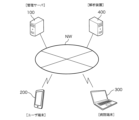
- FIG. 1 is a schematic diagram showing the overall configuration of a health management support system according to an embodiment.
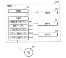
- FIG. 2 is a block diagram showing the internal configuration of a management server.
- FIG. 2 is a block diagram illustrating the internal configuration of a user terminal.
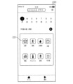
- FIG. 3 is a schematic diagram showing an example of a home screen displayed by a patient application.
- FIG. 3 is a schematic diagram showing an example of a registration item selection screen.
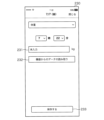
- FIG. 3 is a schematic diagram showing an example of a weight registration screen. It is a schematic diagram which shows an example of a meal recording screen.
- It is a conceptual diagram of a management table.
- It is a conceptual diagram of a measurement value table.
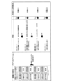
- FIG. 2 is a schematic diagram showing combinations of evaluation categories.
- FIG. 1 is a schematic diagram showing the overall configuration of a health management support system according to an embodiment.
- FIG. 2 is a block diagram showing the internal configuration of a management server.
- FIG. 2 is a block diagram illustrating the internal configuration
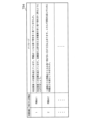
- FIG. 2 is a conceptual diagram showing an example of a group definition table.
- FIG. 2 is an explanatory diagram illustrating a method for identifying a problem.
- FIG. 3 is a conceptual diagram showing an example of a message definition table. 3 is a flowchart showing the procedure of processing executed by the management server.
- FIG. 3 is a schematic diagram showing an example of a message display screen.
- FIG. 1 is a schematic diagram showing the overall configuration of a health management support system according to an embodiment.
- the health management support system according to the present embodiment is a system for supporting diabetes treatment by doctors, and it identifies problems in the lifestyle of diabetic patients (hereinafter referred to as users) and makes improvements to the identified problems.
- One of the features is to provide a prompting message to the user.
- the system includes a management server 100 that supports health management of users, a user terminal 200 used by the user, a hospital terminal 300 used by medical personnel such as doctors, and an analysis device 400 that performs meal image analysis.
- the management server 100, the user terminal 200, the hospital terminal 300, and the analysis device 400 are communicably connected to each other via a communication network NW such as the Internet.
- FIG. 1 only one user terminal 200 is shown for simplification, but multiple user terminals 200 may be connected.
- FIG. 2 is a block diagram showing the internal configuration of the management server 100.
- the management server 100 is a general-purpose or dedicated server device, and includes a control section 101 , a storage section 102 , a communication section 103 , an operation section 104 , and a display section 105 .
- the control unit 101 includes a CPU (Central Processing Unit), a ROM (Read Only Memory), a RAM (Random Access Memory), and the like.
- the CPU included in the control unit 101 deploys various computer programs stored in the ROM and the storage unit 102 on the RAM and executes them, and controls the operation of each hardware part, thereby controlling the entire apparatus as the information processing apparatus of the present application. function as
- the control unit 101 is not limited to the above configuration, and may be any processing circuit or arithmetic circuit including multiple CPUs, multi-core CPUs, GPUs (Graphics Processing Units), microcomputers, volatile or nonvolatile memory, etc. There may be. Further, the control unit 101 may have functions such as a timer that measures the elapsed time from when a measurement start instruction is given until a measurement end instruction is given, a counter that counts, a clock that outputs date and time information, and the like.
- the storage unit 102 includes a storage device using an HDD (Hard Disk Drive), SSD (Solid State Drive), or the like.
- the storage unit 102 stores various computer programs executed by the control unit 101 and data necessary for executing the computer programs.
- the computer programs stored in the storage unit 102 include a treatment support program PG.
- the treatment support program PG acquires user data regarding multiple items indicating diabetes improvement indicators, evaluates the acquired data for each item, determines the evaluation category for each item, and determines the evaluation category for each item.
- the computer program stored in the storage unit 102 is provided by a non-temporary recording medium MD that readably records the computer program.
- the recording medium MD is, for example, a portable memory such as a CD-ROM, a USB (Universal Serial Bus) memory, an SD (Secure Digital) card, a micro SD card, or a Compact Flash (registered trademark).
- the control unit 101 reads a computer program from the recording medium MD using a reading device (not shown), and installs the read computer program into the storage unit 102. Further, the computer program stored in the storage unit 102 may be provided by communication via the communication network NW. In this case, the control unit 101 acquires a computer program through the communication unit 103 and installs the acquired computer program into the storage unit 102.
- the computer program provided by the recording medium MD or by communication may be distributed as a program product.
- the storage unit 102 also temporarily stores a management table TB1 that stores user data regarding a plurality of items indicating diabetes improvement indicators, and measurement values for a predetermined number of days necessary to create this management table TB1. and a measured value table TB2 to be stored.
- the outline of the management table TB1 and the measurement value table TB2 will be specifically explained using FIGS. 8 and 9.
- the storage unit 102 further includes a group definition table TB3 and a message definition table TB4. The outlines of the group definition table TB3 and message definition table TB4 will be specifically explained using FIGS. 11 and 13, respectively.
- the communication unit 103 includes a communication interface for communicating with an external device via the communication network NW.
- the communication interface included in the communication unit 103 is, for example, a communication interface compliant with communication standards such as LAN (Local Area Network) and WiFi (registered trademark).
- the communication unit 103 transmits information to be transmitted to an external device, and receives information transmitted from the external device.
- the operation unit 104 includes an input interface such as a keyboard and a mouse, and accepts operations by an administrator or the like.
- the display unit 105 includes a liquid crystal display device and the like, and displays information to be notified to the administrator and the like.
- the management server 100 is not limited to a single computer, but may be a computer system consisting of multiple computers and peripheral devices. Furthermore, the management server 100 may be a virtual machine virtually constructed using software.
- FIG. 3 is a block diagram illustrating the internal configuration of the user terminal 200.
- the user terminal 200 is a general-purpose computer such as a smartphone, a tablet terminal, or a personal computer, and includes a control section 201, a storage section 202, a communication section 203, an operation section 204, a display section 205, and an imaging section 206.
- the control unit 201 includes, for example, a CPU, ROM, RAM, etc.
- the CPU of the control unit 201 controls the operations of the various hardware described above by loading various programs stored in advance in the ROM or the storage unit 202 into the RAM and executing them.
- control unit 201 is not limited to the above configuration, and may be configured as a single piece of hardware (SoC: System On a Chip) that integrates a processor, memory, storage, communication interface, etc. Further, the control unit 201 may have functions such as a clock that outputs date and time information, a timer that measures the elapsed time from when a measurement start instruction is given until a measurement end instruction is given, and a counter that counts the number of times.
- SoC System On a Chip
- the storage unit 202 includes a storage device using a flash memory, a hard disk, or the like.
- the storage unit 202 stores various computer programs executed by the control unit 201 and data necessary for executing the computer programs.
- the computer program stored in the storage unit 202 is an application program AP (hereinafter referred to as a patient app AP) for recording daily user data such as body weight and meal images, and for displaying messages etc. provided through the management server 100. ).
- the communication unit 203 includes a communication interface for connecting to the communication network NW.
- the communication interface included in the communication unit 203 is, for example, a communication interface compliant with wireless communication standards such as WiFi (registered trademark), 3G, 4G, 5G, and LTE.
- the communication unit 203 transmits various information to be notified to an external device, and receives various information transmitted from the external device to the own device.
- the operation unit 204 includes input devices such as a touch panel and operation buttons, and accepts various operations and inputs of information.
- the control unit 201 performs appropriate control based on the operation information input from the operation unit 204, and stores the information input through the operation unit 204 in the storage unit 202 as necessary.
- the display unit 205 includes a display device such as a liquid crystal display panel or an organic EL display panel, and displays information to be notified to the user based on a control signal output from the control unit 201.
- the imaging unit 206 includes an imaging element such as a CMOS (Complementary Metal Oxide Semiconductor) or a CCD (Charge-Coupled Device), and outputs a digital image obtained by imaging the object.
- the object to be imaged is food and drink that the user himself/herself eats and drinks.
- the user terminal 200 uploads images of food and drink (ie, meal images) captured by the imaging unit 206 to the management server 100 .
- the management server 100 uploads the meal image uploaded from the user terminal 200 to the analysis device 400, and receives information on energy intake and nutrients returned as an analysis result from the analysis device 400.
- the hospital terminal 300 is a dedicated or general-purpose computer such as a personal computer.
- a treatment plan for the user is set, and in the treatment plan, target values for the user's current weight and daily energy intake are set.
- the target value set at the hospital terminal 300 is notified to the user terminal 200 and the management server 100. Note that since the hospital terminal 300 is not a component of the present invention, detailed description thereof will be omitted.
- the analysis device 400 is, for example, a cloud server connected to the communication network NW, and provides a meal image analysis API (Application Programming Interface).
- the analysis device 400 is configured to, when receiving a meal image from an external device such as the management server 100, analyze the meal image using a learning model and return information on intake energy and nutrients. Existing methods are used to analyze meal images.
- the nutrient information returned by the analysis device 400 includes, for example, the amount of protein, fat, carbohydrate, sugar, dietary fiber, salt, vitamins, minerals, etc. contained in the meal. Note that since the analysis device 400 is not a component of the present invention, detailed description thereof will be omitted.
- a user who is a diabetic patient installs a patient application AP on the user terminal 200 according to instructions from a medical professional such as a doctor.
- the user starts the patient application AP on the user terminal 200 and registers daily medical treatment status such as weight, meals, exercise, and blood sugar level through the patient application AP.
- Information on the medical treatment status input through the patient application AP is uploaded to the management server 100 and stored in the storage unit 102 of the management server 100.
- FIG. 4 is a schematic diagram showing an example of a home screen displayed by the patient application AP.
- the control unit 201 causes the display unit 205 to display a home screen 210 as shown in FIG. 4 in accordance with a request from the patient application AP.
- the home screen 210 includes, for example, a medical treatment status display field 211 and a medical treatment status registration button 212.
- a transition is made to a registration item selection screen 220 (see FIG. 5) that accepts selection of items to be registered.
- the medical treatment status display field 211 displays the medical treatment status input by the user.
- FIG. 5 is a schematic diagram showing an example of the registration item selection screen 220.
- the registration item selection screen 220 includes a group of item selection buttons 221.
- the item selection button group 221 includes selection buttons corresponding to, for example, meals, exercise, blood sugar levels, weight, snacks, alcohol, drinks, and other items.
- the user wants to register his/her own weight, the user presses the selection button labeled "Weight"; when the user registers a meal, the selection button labeled "Meal” is pressed.
- the selection button labeled "Weight” When the user registers a meal, the selection button labeled "Meal” is pressed.
- a selection button labeled with the item to be registered is pressed.
- the items may be automatically input in cooperation with other application programs or external measuring instruments.
- application programs that measure exercise for example, number of steps
- the configuration may be such that the measured values are automatically acquired through these application programs.
- technology such as Bluetooth (registered trademark) or NFC (Near Field Communication) is used to link with an external measuring device such as a blood glucose meter or weight scale
- measured values can be obtained from the external measuring device via communication. It may be a configuration.
- FIG. 6 is a schematic diagram showing an example of the weight registration screen 230.
- the weight registration screen 230 shown in FIG. 6 is an example of a screen displayed on the display unit 205 of the user terminal 200 when a selection button labeled with weight is pressed on the registration item selection screen 220.
- the weight registration screen 230 includes a weight input field 231, a device cooperation button 232, and a save button 233.
- the user can manually input his or her own measured weight into the weight input field 231. Further, the user may press the device link button 232 to link the device with the scale, and transmit the weight value measured by the scale to the user terminal 200.
- the save button 233 is a button for saving the weight value input through the weight registration screen 230.
- FIG. 7 is a schematic diagram showing an example of the meal recording screen 240.
- the meal record screen 240 shown in FIG. 7 is an example of a screen that is displayed on the display unit 205 of the user terminal 200 when the selection button labeled Meal is pressed on the registration item selection screen 220.
- the meal record screen 240 includes, for example, a type selection field 241, a meal input field 242, a photo display field 243, a photo selection button 244, a memo input field 245, and a save button 246.
- the type selection column 241 accepts meal types including breakfast, lunch, dinner, and snacks.
- the meal input field 242 accepts information on meals such as pasta and sweets.
- the photo display field 243 displays the meal image selected by operating the photo selection button 244.
- the photo selection button 244 When the photo selection button 244 is pressed, it activates the imaging unit 206 of the user terminal 200 and displays a button for newly capturing an image and a button for selecting from pre-imaged meal images.
- the memo input field 245 accepts the user's memo regarding meals.
- the save button 246 is a button for saving the contents input through the meal record screen 240.
- the contents input through the meal record screen 240 are stored in the storage unit 202 of the user terminal 200, and are also transmitted to the management server 100 and stored in the storage unit 102 of the management server 100.
- the management server 100 transmits the meal image input through the meal record screen 240 to the analysis device 400, receives the information on the intake energy and nutrients returned from the analysis device 400, and calculates the received energy and nutrients.
- the information is stored in the storage unit 102.
- the user terminal 200 may directly transmit the meal image input through the meal record screen 240 to the analysis device 400.
- the user terminal 200 receives the information on intake energy and nutrients returned from the analysis device 400, transfers the received information on intake energy and nutrients to the management server 100, and stores it in the storage unit 102 of the management server 100. It is good to memorize it.
- FIG. 8 is a conceptual diagram of the management table TB1
- FIG. 9 is a conceptual diagram of the measured value table TB2.
- the management table TB1 stores the user's current weight, change in weight, daily energy intake, and change in energy intake in association with dates as data for items indicating diabetes improvement indicators.
- the average value of the weight measurements from the previous day to seven days ago (that is, the average weight for the past week) is used as the current weight.
- the user's weight on that day is measured by the user using a scale.
- the measured value input into the user terminal 200 is transmitted to the management server 100 via the communication network NW, and is stored in the measured value table TB2 as the current day's weight measured value.
- the control unit 101 of the management server 100 calculates the average weight for the past week based on the weight measurements stored in the measurement value table TB2 at a predetermined timing (for example, 7:00 in the morning), and calculates the average weight for the past week.
- the weight is stored in the management table TB1 as the current weight.
- the change in body weight compared to two weeks ago is used for the change in body weight.
- the control unit 101 converts the current weight calculated as described above to the average value of the weight measurements from 8 days to 14 days ago (i.e., the average weight from 2 weeks ago). By dividing by , the change in body weight is calculated, and the calculated value is stored in the management table TB1 as the change in body weight.
- control unit 101 in order to calculate the current weight and changes in weight, measured values of weight for the past two weeks including the current day are required. Therefore, when the control unit 101 acquires a weight measurement value from the user terminal 200, the control unit 101 stores the acquired measurement values in the measurement value table TB2 in date order, and stores the measurement values for two weeks including the current day in the measurement value table TB2. and hold it.
- the total value of the energy intake on the previous day (that is, the total energy intake for the day) is used.
- the user takes a meal including breakfast, lunch, dinner, and snacks
- Capture of food and drink images and uploading of meal images are performed using the user terminal 200.
- the management server 100 uploads the meal image uploaded from the user terminal 200 to the analysis device 400, receives from the analysis device 400 the value of the intake energy that the user ingests from the meal, and stores it in the storage unit 102.
- the control unit 101 calculates the total value of the previous day's intake energy by adding the values of the previous day's intake energy stored in the storage unit 102, and calculates the total value of the intake energy of the previous day, and displays the management table TB1.
- the measured value table TB2 is stored as the daily energy intake.
- the change in energy intake For the change in energy intake, the change in energy intake compared to the average value of total energy intake for each day from 8 to 14 days ago (that is, the average value of total energy intake for 2 weeks ago) is used. At a predetermined timing (for example, 7:00 in the morning), the control unit 101 calculates the change in energy intake by dividing the previous day's total energy intake by the average value of the total energy intake for each day two weeks ago. Then, the calculated value of the change in intake energy is stored in the management table TB1.
- control unit 101 aggregates the intake energy for each day and stores it in the measurement value table TB2 in date order, and holds the intake energy values for two weeks including the current day in the measurement value table TB2.
- the management server 100 manages the measurement values of multiple users, it is preferable to store data related to each item in the management table TB1 and the measurement value table TB2 in association with the user ID that identifies each user.
- the control unit 101 of the management server 100 determines the evaluation classification for each item by referring to the management table TB1 and comparing the value of each item with the target value or determination value. For example, the control unit 101 determines whether the current weight stored in the management table TB1 is over the target, achieved the target, or under the target by comparing the current weight with the target value.
- the target value of the current body weight is set for each user by a medical professional such as a doctor, and is stored in the storage unit 102 of the management server 100.
- the control unit 101 calculates the target value by dividing the current weight by the target value, and if the target value exceeds 100%, the target is exceeded, if it is from over 90% to 100%, the target is achieved, and if it is 90% or less, the target is achieved. If so, it is considered to be less than the target. Further, the control unit 101 refers to the measured value table TB2, and if it is determined that the measured values for 5 days or more are missing among the measured values for 7 days used to calculate the current weight, the control unit 101 The evaluation is determined to be indeterminate.
- the control unit 101 of the management server 100 determines whether the intake energy is exceeded, achieved, or less than the target by comparing it with the target value set by a medical professional such as a doctor. Furthermore, if there is no record of the daily intake energy in the management table TB1, the control unit 101 determines that the evaluation of the intake energy cannot be determined.
- control unit 101 determines whether the change in body weight is increased, maintained, or decreased by comparing the change in body weight stored in the management table TB1 with the determination value.
- the determination value is set by the management server 100.
- the control unit 101 refers to the measurement value table TB2 and calculates the value of (average value of weight measurements from the previous day to 7 days ago)/(average value of weight measurements from 8 days to 14 days ago) x 100. If the calculated value is 101% or more, it is determined to increase, if it is 99% or more and less than 101%, it is determined to be maintained, and if it is less than 99%, it is determined to be decreased.
- control unit 101 refers to the measurement value table TB2 and determines that among the weight measurements from the previous day to 7 days ago, the measurement values for 5 days or more are missing, or if the weight measurements from 8 days to 14 days ago are missing. If it is determined that the measured values for 5 days or more are missing among the measured body weight values, it is determined that the evaluation of the weight change cannot be determined.
- control unit 101 of the management server 100 determines whether to increase, maintain, or decrease based on the set determination value. Further, when it is determined that measured values for a predetermined number of days or more are missing with reference to the measured value table TB2, the control unit 101 determines that evaluation of changes in intake energy cannot be determined.
- the management server 100 specifies a group from the combination of evaluation categories by referring to the group definition table TB3, and determines an action in the patient application AP to be executed in the user terminal 200 according to the specified group.
- FIG. 11 is a conceptual diagram showing an example of the group definition table TB3. Due to space limitations, the example in FIG. 11 shows only some of the 20 groups G01 to G20.
- Group 1 (G01) is defined as a group whose daily energy intake exceeds the target, and it is preferable to encourage a reduction in energy intake. Some of the combinations of evaluation categories belonging to group 1 are shown in FIG. Even if the daily energy intake exceeds the target, if the energy intake has decreased compared to two weeks ago or the current weight does not exceed the target, the user's daily life They are excluded from Group 1 because their customs are considered to be different. Further, as an action of the patient application AP for group 1, prompting for a reduction in intake energy is defined.
- the daily energy intake exceeds the target at the moment, but the energy intake has decreased compared to 2 weeks ago. It is defined as a group in which it is preferable to promote energy reduction. Some of the combinations of evaluation categories belonging to group 2 are shown in FIG. Currently, your daily energy intake exceeds your target, but even if your energy intake has decreased compared to two weeks ago, your current weight may be at the target, below the target, or cannot be determined. In this case, the users are excluded from Group 2 because their lifestyle habits are considered to be different. Further, as an action of the patient application AP for group 2, it is defined that the reduction in intake energy is evaluated and a further reduction in intake energy is encouraged.
- FIG. 12 is an explanatory diagram illustrating a method for identifying problems.
- Group 1 is defined as a group whose daily energy intake exceeds the target, and it is preferable to encourage a reduction in energy intake.
- the previous day's value is outside the target range
- the number of days exceeding the set threshold exceeds the set threshold for a certain period or more
- the value exceeds the set threshold for a certain period or more in the past few days.
- a plurality of determination elements including the number of times or more are set.
- Judgment factors are selected from blood sugar level, intake amount and ratio of carbohydrates and fats, and number of registered snacks.
- the control unit 101 of the management server 100 identifies problems in the user's lifestyle based on a plurality of determination factors set for group 1. For example, if the control unit 101 determines that determination factor 1 is satisfied, it can identify problem 1 in the user's lifestyle. Furthermore, if the control unit 101 determines that determination factor 2 is satisfied without satisfying determination factor 1, it is possible to identify problem point 2 in the user's lifestyle. In this way, the control unit 101 can identify problems in the user's lifestyle by making determinations in the order of determination element 1, determination element 2, . . . , determination element 3. Problems are selected from the following: high sugar content, high carbohydrate content, and frequent snacking.
- the information used for the determination may be input by the user himself/herself. Further, the intake amount of carbohydrates and fats can be based on the nutrient information acquired from the analysis device 400 and stored in the storage unit 102.
- FIG. 13 is a conceptual diagram showing an example of the message definition table TB4.
- the following messages are displayed: ⁇ Judgment element 1 exceeds the target.Are you eating too much of the food that corresponds to problem 1?'' and ⁇ Judgment element 1 exceeds the target. "Try to eat lots of foods rich in nutrients that suppress increases in blood sugar levels," the message reads. The same applies to other problems, and one or more messages are set for each problem.
- control unit 101 When multiple messages are set for one problem, the control unit 101 randomly selects one message from the multiple messages, reads it from the message definition table TB4, and sends the read message to the user. All you have to do is present it. Alternatively, the control unit 101 may present multiple messages to the user in a particular order. If no problem has been identified, or if no problem has been identified, the control unit 101 may present a message prepared in advance to the user.
- FIG. 14 is a flowchart showing the procedure of processing executed by the management server 100.
- the control unit 101 of the management server 100 receives the weight value transmitted from the user terminal 200 and the intake energy value transmitted from the analysis device 400, the control unit 101 performs the control unit 101 at a predetermined timing (for example, 7:00 in the morning). , updates the measured value table TB2 (step S101), calculates the values of a plurality of items indicating diabetes improvement indicators based on the measured values stored in the measured value table TB2, and stores the calculation results in the management table TB1.
- current body weight, weight change, daily energy intake, and change in energy intake are used as values indicating diabetes improvement indicators.
- the control unit 101 evaluates the values of each item stored in the management table TB1 and determines the evaluation category (step S103).
- the control unit 101 compares the current body weight and daily energy intake with target values set for each user by a medical professional such as a doctor, and determines whether the target is exceeded, achieved, or less than the target. Further, the control unit 101 refers to the measured value table TB2 and determines that the determination is not possible if the measured values for a predetermined number of days are not recorded. On the other hand, increase, maintenance, or decrease is determined by comparing changes in body weight with two weeks ago, and changes in energy intake by comparing with two weeks ago. Further, the control unit 101 refers to the measured value table TB2 and determines that the determination is not possible if the measured values for a predetermined number of days are not recorded.
- the control unit 101 determines a group corresponding to the combination of evaluation categories determined in step S103 by referring to the group definition table TB3 (step S104).
- groups are defined so that users have common lifestyle habits (medical treatment information).
- the control unit 101 identifies problems in the user's lifestyle by making a determination using the determination factors set for each group (step S105).
- control unit 101 refers to the message definition table TB4 and selects a message to be presented to the user (step S106). If a plurality of messages for prompting improvement for one problem are registered, the control unit 101 may randomly select one message from among the plurality of registered messages.
- FIG. 15 is a schematic diagram showing an example of the message display screen 250.
- Message display screen 250 in FIG. 15 shows an example of a screen displayed on display unit 205 of user terminal 200 when a message transmitted from management server 100 is received.
- a message received from the management server 100 is displayed on the message display screen 250, and can prompt the user to improve their lifestyle habits.
- current body weight, weight change, daily energy intake, and change in energy intake are used as items indicating diabetes improvement indicators, but the present invention is not limited to these. Items such as amount of exercise (for example, number of steps), change in amount of exercise, exercise time, change in exercise time, etc. may be used.
- the determination of evaluation categories, identification of problems, and message selection are executed in the management server 100, but they may be executed in the user terminal 200.
- the treatment support program PG is installed on the user terminal 200, and each table TB1 to TB4 is prepared in the storage section 202 of the user terminal 200.
- Management server 101 Control unit 102 Storage unit 103 Communication unit 104 Operation unit 105 Display unit 200 User terminal 300 Hospital terminal 400 Analysis device AP Patient application PG Treatment support program TB1 Management table TB2 Measured value table TB3 Group definition table TB4 Message definition table NW communication network
Landscapes
- Health & Medical Sciences (AREA)
- Engineering & Computer Science (AREA)
- Epidemiology (AREA)
- General Health & Medical Sciences (AREA)
- Medical Informatics (AREA)
- Primary Health Care (AREA)
- Public Health (AREA)
- Medical Treatment And Welfare Office Work (AREA)
Abstract
Description
図1は実施の形態に係る健康管理支援システムの全体構成を示す模式図である。本実施の形態に係る健康管理支援システムは、医師による糖尿病治療を支援するためのシステムであり、糖尿病患者(以下、ユーザという)の生活習慣における問題点を特定し、特定した問題点について改善を促すメッセージをユーザに提供することを特徴の1つとする。
管理サーバ100の制御部101は、管理テーブルTB1を参照し、各項目の値を目標値又は判定値と比較することにより、項目毎に評価区分を決定する。例えば、制御部101は、管理テーブルTB1に記憶されている現体重を目標値と比較することにより、目標超過、目標達成、目標未満を判断する。現体重の目標値は、医師等の医療従事者によってユーザ毎に設定され、管理サーバ100の記憶部102に記憶される。制御部101は、現体重を目標値で除算して対目標値を求め、対目標値が100%超であれば目標超過、90%超から100%以下であれば目標達成、90%以下であれば目標未満と判断する。また、制御部101は、測定値テーブルTB2を参照し、現体重の計算に使用される7日分の測定値のうち、5日以上の測定値が欠落していると判断した場合、現体重の評価を判定不可と判断する。
上述したように評価区分の組み合わせは256通り存在するが、ユーザの生活習慣(療養状況)が共通するように評価区分の組み合わせを分類することで、256通りの組み合わせを例えば20個のグループに分類することができる。管理サーバ100は、グループ定義テーブルTB3を参照することにより、評価区分の組み合わせからグループを特定し、特定したグループに応じて、ユーザ端末200において実行される患者アプリAPでのアクションを決定する。
ユーザの生活習慣における問題点を特定するために、本実施の形態では、グループ毎に複数の判定要素が設定されている。以下、グループ1を例にとり、問題点の特定方法について説明する。
管理サーバ100の制御部101は、特定した問題点について、ユーザに改善を促すメッセージを出力する。図13はメッセージ定義テーブルTB4の一例を示す概念図である。図13の例では、問題点1に対し、「判定要素1が目標を超えています。問題点1となる食べ物を多く食べていませんか。」というメッセージ、及び「判定要素1が目標を超えています。血糖値の上昇を抑える栄養素の多い食べ物を多く摂るように心がけましょう。」というメッセージが設定されている。他の問題点についても同様であり、各問題点に対して、1又は複数のメッセージが設定されている。1つの問題点に対して複数のメッセージが設定されている場合、制御部101は、複数のメッセージから1つのメッセージをランダムに選択してメッセージ定義テーブルTB4から読み出し、読み出した1つのメッセージをユーザに提示すればよい。代替的に、制御部101は、複数のメッセージを特定の順序でユーザに提示してもよい。特定された問題がない場合、あるいは問題の特定が行われなかった場合、制御部101は、予め用意されたメッセージをユーザに提示してもよい。
図14は管理サーバ100が実行する処理の手順を示すフローチャートである。管理サーバ100の制御部101は、ユーザ端末200から送信される体重の値、及び解析装置400から送信される摂取エネルギの値を受信した場合、所定のタイミング(例えば、朝の7:00)で、測定値テーブルTB2を更新する(ステップS101)とともに、測定値テーブルTB2に記憶されている測定値を基に、糖尿病の改善指標を示す複数の項目の値を計算し、計算結果を管理テーブルTB1に記憶させる(ステップS102)。実施の形態では、糖尿病の改善指標を示す値として、現体重、体重変化、1日の摂取エネルギ、摂取エネルギの変化を用いる。
101 制御部
102 記憶部
103 通信部
104 操作部
105 表示部
200 ユーザ端末
300 病院端末
400 解析装置
AP 患者アプリ
PG 治療支援プログラム
TB1 管理テーブル
TB2 測定値テーブル
TB3 グループ定義テーブル
TB4 メッセージ定義テーブル
NW 通信ネットワーク
Claims (8)
- 糖尿病の改善指標を示す複数の項目についてユーザのデータを取得し、
取得したデータを項目毎に評価して、項目毎の評価区分を決定し、
各項目の評価区分の組み合わせに応じて設定される複数の判定要素に基づき、前記ユーザの生活習慣における問題点を特定し、
特定した問題点について、改善を促すメッセージを出力する
処理をコンピュータに実行させるためのコンピュータプログラム。 - 前記項目は、ユーザの体重、体重の変化、摂取エネルギ、及び摂取エネルギの変化を含む
請求項1に記載のコンピュータプログラム。 - 項目毎のデータを目標値又は判定値と比較することにより、評価区分を決定する
請求項1に記載のコンピュータプログラム。 - 前記目標値又は前記判定値と比較すべきデータを欠いている場合、判定不可との評価区分を決定する
請求項3に記載のコンピュータプログラム。 - 前記複数の判定要素は、前記評価区分の組み合わせに応じて定められるグループ毎に設定してある
請求項1から請求項4の何れか1つに記載のコンピュータプログラム。 - ユーザの生活習慣が共通性を有するように前記グループを規定してある
請求項5に記載のコンピュータプログラム。 - 糖尿病の改善指標を示す複数の項目についてユーザのデータを取得する取得部と、
取得したデータを項目毎に評価して、項目毎の評価区分を決定する決定部と、
各項目の評価区分の組み合わせに応じて設定される複数の判定要素に基づき、前記ユーザの生活習慣における問題点を特定する特定部と、
特定した問題点について、改善を促すメッセージを出力する出力部と
を備える情報処理装置。 - 糖尿病の改善指標を示す複数の項目についてユーザのデータを取得し、
取得したデータを項目毎に評価して、項目毎の評価区分を決定し、
各項目の評価区分の組み合わせに応じて設定される複数の判定要素に基づき、前記ユーザの生活習慣における問題点を特定し、
特定した問題点について、改善を促すメッセージを出力する
処理をコンピュータにより実行する情報処理方法。
Priority Applications (2)
| Application Number | Priority Date | Filing Date | Title |
|---|---|---|---|
| CN202380035634.8A CN119072752A (zh) | 2022-04-25 | 2023-04-21 | 计算机程序、信息处理装置以及信息处理方法 |
| JP2024517271A JPWO2023210514A1 (ja) | 2022-04-25 | 2023-04-21 |
Applications Claiming Priority (2)
| Application Number | Priority Date | Filing Date | Title |
|---|---|---|---|
| JP2022071857 | 2022-04-25 | ||
| JP2022-071857 | 2022-04-25 |
Publications (1)
| Publication Number | Publication Date |
|---|---|
| WO2023210514A1 true WO2023210514A1 (ja) | 2023-11-02 |
Family
ID=88518811
Family Applications (1)
| Application Number | Title | Priority Date | Filing Date |
|---|---|---|---|
| PCT/JP2023/015847 Ceased WO2023210514A1 (ja) | 2022-04-25 | 2023-04-21 | コンピュータプログラム、情報処理装置、及び情報処理方法 |
Country Status (3)
| Country | Link |
|---|---|
| JP (1) | JPWO2023210514A1 (ja) |
| CN (1) | CN119072752A (ja) |
| WO (1) | WO2023210514A1 (ja) |
Citations (2)
| Publication number | Priority date | Publication date | Assignee | Title |
|---|---|---|---|---|
| JP2014076113A (ja) * | 2012-10-09 | 2014-05-01 | Lets Sports Co Ltd | 健康支援タイプ別に重力への順応性とエネルギー消費量を算定し、最適な健康支援プログラムを提供するための方法及びシステム |
| JP2021026556A (ja) * | 2019-08-06 | 2021-02-22 | 大日本印刷株式会社 | 生活習慣改善支援装置、端末装置、コンピュータプログラム及び生活習慣改善支援方法 |
-
2023
- 2023-04-21 WO PCT/JP2023/015847 patent/WO2023210514A1/ja not_active Ceased
- 2023-04-21 CN CN202380035634.8A patent/CN119072752A/zh active Pending
- 2023-04-21 JP JP2024517271A patent/JPWO2023210514A1/ja active Pending
Patent Citations (2)
| Publication number | Priority date | Publication date | Assignee | Title |
|---|---|---|---|---|
| JP2014076113A (ja) * | 2012-10-09 | 2014-05-01 | Lets Sports Co Ltd | 健康支援タイプ別に重力への順応性とエネルギー消費量を算定し、最適な健康支援プログラムを提供するための方法及びシステム |
| JP2021026556A (ja) * | 2019-08-06 | 2021-02-22 | 大日本印刷株式会社 | 生活習慣改善支援装置、端末装置、コンピュータプログラム及び生活習慣改善支援方法 |
Also Published As
| Publication number | Publication date |
|---|---|
| JPWO2023210514A1 (ja) | 2023-11-02 |
| CN119072752A (zh) | 2024-12-03 |
Similar Documents
| Publication | Publication Date | Title |
|---|---|---|
| JP6566241B2 (ja) | 健康管理システム、健康管理装置及び表示方法 | |
| EP3454338B1 (en) | Meal advice providing system and analysis device | |
| JP7032072B2 (ja) | 情報処理装置、情報処理方法、及びプログラム | |
| CN104207753A (zh) | 个人健康监视系统 | |
| KR102004438B1 (ko) | 사용자 건강습관정보 수집을 통한 건강관리 서비스 제공 장치 및 제공 방법 | |
| JP7018937B2 (ja) | 基礎投与のタイミングを調節するためのシステムおよび方法 | |
| EP3567594A1 (en) | Diabetes management system with dynamic selection of prediction logic | |
| JP2021026556A (ja) | 生活習慣改善支援装置、端末装置、コンピュータプログラム及び生活習慣改善支援方法 | |
| JP7349759B1 (ja) | プログラム、方法、情報処理装置 | |
| US20150212096A1 (en) | Diet Support Device, Method, and Recording Medium Stored with Program | |
| JPWO2018012222A1 (ja) | アドバイス情報提供システム及びアドバイス情報提供プログラムを記録した記録媒体 | |
| US20210134435A1 (en) | Behavior modification assistance device, terminal, and server | |
| Magrini et al. | Wearable devices for caloric intake assessment: state of art and future developments | |
| US20230142776A1 (en) | Parent-child health management system, parent-child health analysis device, and parent-child health management method | |
| TWI668664B (zh) | Method for dynamically analyzing blood sugar level, system thereof and computer program product | |
| JP2004302498A (ja) | 食生活習慣改善支援装置 | |
| JP7469040B2 (ja) | 情報処理装置、情報処理方法、情報処理プログラム、および情報処理システム | |
| KR20210135406A (ko) | 원격 의료 상담 시스템 | |
| JP7760232B2 (ja) | 生体情報データ共有システム | |
| JP2021120627A (ja) | 健康状態判定支援装置、健康状態判定支援プログラム、および健康状態判定支援システム | |
| WO2021209989A1 (en) | Improvement of disease prevention, diagnosis and treatment by application of multiple information sources | |
| KR20240108282A (ko) | 당뇨병 관리 서비스 방법 및 장치 | |
| US20230284938A1 (en) | Information processing apparatus and information processing program | |
| JP6992505B2 (ja) | 情報処理装置、方法及びプログラム | |
| JP6906179B2 (ja) | 体動分析システム、体動分析方法及びプログラム |
Legal Events
| Date | Code | Title | Description |
|---|---|---|---|
| 121 | Ep: the epo has been informed by wipo that ep was designated in this application |
Ref document number: 23796256 Country of ref document: EP Kind code of ref document: A1 |
|
| WWE | Wipo information: entry into national phase |
Ref document number: 2024517271 Country of ref document: JP |
|
| WWE | Wipo information: entry into national phase |
Ref document number: 202380035634.8 Country of ref document: CN |
|
| NENP | Non-entry into the national phase |
Ref country code: DE |
|
| 122 | Ep: pct application non-entry in european phase |
Ref document number: 23796256 Country of ref document: EP Kind code of ref document: A1 |