WO2023209906A1 - 端末、及び基地局 - Google Patents
端末、及び基地局 Download PDFInfo
- Publication number
- WO2023209906A1 WO2023209906A1 PCT/JP2022/019191 JP2022019191W WO2023209906A1 WO 2023209906 A1 WO2023209906 A1 WO 2023209906A1 JP 2022019191 W JP2022019191 W JP 2022019191W WO 2023209906 A1 WO2023209906 A1 WO 2023209906A1
- Authority
- WO
- WIPO (PCT)
- Prior art keywords
- terminal
- base station
- positioning
- drx
- signal
- Prior art date
Links
- 230000008054 signal transmission Effects 0.000 claims abstract description 60
- 230000005540 biological transmission Effects 0.000 abstract description 48
- 230000000737 periodic effect Effects 0.000 abstract description 7
- 238000004891 communication Methods 0.000 description 70
- 230000004913 activation Effects 0.000 description 48
- 238000000034 method Methods 0.000 description 27
- 238000010586 diagram Methods 0.000 description 25
- 230000006870 function Effects 0.000 description 22
- 238000005516 engineering process Methods 0.000 description 16
- 238000012545 processing Methods 0.000 description 10
- 230000004044 response Effects 0.000 description 8
- 230000008859 change Effects 0.000 description 7
- 230000011664 signaling Effects 0.000 description 7
- 230000008569 process Effects 0.000 description 6
- 238000005259 measurement Methods 0.000 description 5
- 238000002360 preparation method Methods 0.000 description 5
- 238000001514 detection method Methods 0.000 description 4
- 238000010295 mobile communication Methods 0.000 description 4
- 230000007704 transition Effects 0.000 description 4
- 230000001133 acceleration Effects 0.000 description 3
- 230000002776 aggregation Effects 0.000 description 3
- 238000004220 aggregation Methods 0.000 description 3
- 238000013473 artificial intelligence Methods 0.000 description 3
- 238000004364 calculation method Methods 0.000 description 3
- 238000007726 management method Methods 0.000 description 3
- 238000013507 mapping Methods 0.000 description 3
- 238000012986 modification Methods 0.000 description 3
- 230000004048 modification Effects 0.000 description 3
- 125000004122 cyclic group Chemical group 0.000 description 2
- 230000009977 dual effect Effects 0.000 description 2
- 230000007774 longterm Effects 0.000 description 2
- 230000003287 optical effect Effects 0.000 description 2
- 235000015842 Hesperis Nutrition 0.000 description 1
- 235000012633 Iberis amara Nutrition 0.000 description 1
- 230000009471 action Effects 0.000 description 1
- 230000006978 adaptation Effects 0.000 description 1
- 239000000969 carrier Substances 0.000 description 1
- 238000012508 change request Methods 0.000 description 1
- 239000003795 chemical substances by application Substances 0.000 description 1
- 238000012790 confirmation Methods 0.000 description 1
- 230000008878 coupling Effects 0.000 description 1
- 238000010168 coupling process Methods 0.000 description 1
- 238000005859 coupling reaction Methods 0.000 description 1
- 238000009795 derivation Methods 0.000 description 1
- 230000006866 deterioration Effects 0.000 description 1
- 230000000694 effects Effects 0.000 description 1
- 239000000835 fiber Substances 0.000 description 1
- 238000001914 filtration Methods 0.000 description 1
- 238000011835 investigation Methods 0.000 description 1
- 239000006249 magnetic particle Substances 0.000 description 1
- 238000012544 monitoring process Methods 0.000 description 1
- 230000002093 peripheral effect Effects 0.000 description 1
- 238000013468 resource allocation Methods 0.000 description 1
- 238000013519 translation Methods 0.000 description 1
Images


Classifications
-
- H—ELECTRICITY
- H04—ELECTRIC COMMUNICATION TECHNIQUE
- H04W—WIRELESS COMMUNICATION NETWORKS
- H04W52/00—Power management, e.g. TPC [Transmission Power Control], power saving or power classes
- H04W52/02—Power saving arrangements
-
- H—ELECTRICITY
- H04—ELECTRIC COMMUNICATION TECHNIQUE
- H04W—WIRELESS COMMUNICATION NETWORKS
- H04W64/00—Locating users or terminals or network equipment for network management purposes, e.g. mobility management
-
- H—ELECTRICITY
- H04—ELECTRIC COMMUNICATION TECHNIQUE
- H04W—WIRELESS COMMUNICATION NETWORKS
- H04W72/00—Local resource management
- H04W72/04—Wireless resource allocation
-
- Y—GENERAL TAGGING OF NEW TECHNOLOGICAL DEVELOPMENTS; GENERAL TAGGING OF CROSS-SECTIONAL TECHNOLOGIES SPANNING OVER SEVERAL SECTIONS OF THE IPC; TECHNICAL SUBJECTS COVERED BY FORMER USPC CROSS-REFERENCE ART COLLECTIONS [XRACs] AND DIGESTS
- Y02—TECHNOLOGIES OR APPLICATIONS FOR MITIGATION OR ADAPTATION AGAINST CLIMATE CHANGE
- Y02D—CLIMATE CHANGE MITIGATION TECHNOLOGIES IN INFORMATION AND COMMUNICATION TECHNOLOGIES [ICT], I.E. INFORMATION AND COMMUNICATION TECHNOLOGIES AIMING AT THE REDUCTION OF THEIR OWN ENERGY USE
- Y02D30/00—Reducing energy consumption in communication networks
- Y02D30/70—Reducing energy consumption in communication networks in wireless communication networks
Definitions
- the present invention relates to a terminal and a base station in a wireless communication system.
- NR New Radio
- LTE Long Term Evolution
- a discontinuous reception (DRX) operation is defined in which the terminal periodically attempts to receive paging messages from the network (for example, Non-Patent Document 2).
- DRX discontinuous reception
- a terminal configured for discontinuous reception (DRX) operation may not be able to properly transmit or receive signals for positioning.
- the present invention has been made in view of the above points, and an object of the present invention is to provide a technology that enables a terminal that performs intermittent reception to appropriately transmit or receive signals for positioning. do.
- a transmitting unit that transmits information regarding intermittent reception to a network; a control unit that assumes transmitting or receiving signals for positioning in accordance with the timing of intermittent reception; A terminal is provided.
- a technology that allows a terminal that performs an intermittent reception operation to appropriately transmit or receive a signal for positioning.
- FIG. 1 is a diagram for explaining a wireless communication system in an embodiment of the present invention.
- FIG. 1 is a diagram for explaining a wireless communication system in an embodiment of the present invention.
- FIG. 3 is a diagram for explaining the operation of a terminal.
- FIG. 7 is a diagram for explaining an example of operation in the 0th embodiment.
- FIG. 7 is a diagram for explaining an example of operation in the 0th embodiment.
- FIG. 3 is a diagram for explaining an example of operation in the first embodiment.
- FIG. 3 is a diagram for explaining an example of operation in the first embodiment.
- FIG. 3 is a diagram for explaining an example of operation in the first embodiment.
- FIG. 7 is a diagram for explaining an example of operation in a third embodiment.
- FIG. 7 is a diagram for explaining an example of operation in a third embodiment.
- FIG. 7 is a diagram for explaining an example of operation in a third embodiment.
- FIG. 7 is a diagram for explaining an example of operation in a third embodiment.
- FIG. 7 is a diagram for explaining an example of operation in a third embodiment.
- It is a diagram showing an example of the configuration of the base station 10 (LMF 30).
- 2 is a diagram showing a configuration example of a terminal 20.
- FIG. It is a diagram showing an example of the hardware configuration of base station 10, terminal 20, or LMF 30 in an embodiment of the present invention.
- 1 is a diagram showing an example of the configuration of a vehicle.
- Existing technologies are used as appropriate for the operation of the wireless communication system according to the embodiment of the present invention.
- the existing technology is, for example, existing LTE or existing NR, but is not limited to existing LTE or NR.
- the SS Synchronization signal
- PSS Primary SS
- SSS Secondary SS
- PBCH Physical broadcast channel
- PRACH Physical broadcast channel
- PDCCH Physical Downlink Control Channel
- PDSCH Physical Downlink Shared Channel
- PUCCH Physical Uplink Control Channel
- PUSCH Physical Uplink Shared Channel
- NR corresponds to NR-SS, NR-PSS, NR-SSS, NR-PBCH, NR-PRACH, etc.
- NR- the above terms in NR correspond to NR-SS, NR-PSS, NR-SSS, NR-PBCH, NR-PRACH, etc.
- NR- the signal is used for NR, it is not necessarily specified as "NR-".
- the duplex method may be a TDD (Time Division Duplex) method, an FDD (Frequency Division Duplex) method, or another method (for example, Flexible Duplex, etc.). This method may also be used.
- configure the wireless parameters etc. may mean pre-configuring a predetermined value, or may mean that the base station 10 or Wireless parameters notified from the terminal 20 may also be set.
- FIG. 1 is a diagram showing a configuration example (1) of a wireless communication system according to an embodiment of the present invention.
- a wireless communication system according to an embodiment of the present invention includes a base station 10 and a terminal 20, as shown in FIG.
- an LMF (Location Management Function) 30 is shown as an example of a network device.
- the LMF 30 may also be called a position management device.
- LMF 30 includes a function of calculating the position of a terminal based on measurement results from terminal 20 or base station 10.
- the LMF 30 includes a function of transmitting support information (assistance data) to the base station 10 and the like.
- one base station 10 and one terminal 20 are shown in FIG. 1, this is just an example, and there may be a plurality of each.
- the base station 10 is a communication device that provides one or more cells and performs wireless communication with the terminal 20.
- the physical resources of a radio signal are defined in the time domain and the frequency domain, and the time domain may be defined by the number of OFDM (Orthogonal Frequency Division Multiplexing) symbols, and the frequency domain may be defined by the number of subcarriers or resource blocks. Good too.
- Base station 10 transmits a synchronization signal and system information to terminal 20.
- the synchronization signals are, for example, NR-PSS and NR-SSS.
- System information is transmitted, for example, on NR-PBCH, and is also referred to as broadcast information.
- the synchronization signal and system information may be called SSB (SS/PBCH block). As shown in FIG.
- the base station 10 transmits a control signal or data to the terminal 20 on the DL (Downlink), and receives the control signal or data from the terminal 20 on the UL (Uplink). Both the base station 10 and the terminal 20 can perform beamforming to transmit and receive signals. Further, both the base station 10 and the terminal 20 can apply MIMO (Multiple Input Multiple Output) communication to DL or UL. Further, both the base station 10 and the terminal 20 may communicate via a secondary cell (SCell) and a primary cell (PCell) using CA (Carrier Aggregation). Furthermore, the terminal 20 may communicate via a primary cell of the base station 10 and a primary SCG cell (PSCell) of another base station 10 using DC (Dual Connectivity).
- SCell secondary cell
- PCell primary cell
- DC Direct Connectivity
- the terminal 20 is a communication device equipped with a wireless communication function, such as a smartphone, a mobile phone, a tablet, a wearable terminal, or a communication module for M2M (Machine-to-Machine). As shown in FIG. 1, the terminal 20 receives control signals or data from the base station 10 via DL, and transmits control signals or data to the base station 10 via UL, thereby receiving various types of information provided by the wireless communication system. Use communication services. Furthermore, the terminal 20 receives various reference signals transmitted from the base station 10, and measures the channel quality based on the reception results of the reference signals.
- a wireless communication function such as a smartphone, a mobile phone, a tablet, a wearable terminal, or a communication module for M2M (Machine-to-Machine).
- M2M Machine-to-Machine
- the terminal 20 is capable of performing carrier aggregation in which multiple cells (multiple CCs (Component Carriers)) are bundled to communicate with the base station 10.
- multiple CCs Component Carriers
- carrier aggregation one PCell (Primary cell) and one or more SCells (Secondary cells) are used.
- SCells Secondary cells
- PUCCH-SCell with PUCCH may be used.
- FIG. 2 is a diagram for explaining an example (2) of a wireless communication system according to an embodiment of the present invention.
- FIG. 2 shows an example of the configuration of a wireless communication system when dual connectivity (DC) is implemented.
- a base station 10A serving as an MN (Master Node) and a base station 10B serving as an SN (Secondary Node) are provided.
- Base station 10A and base station 10B are each connected to a core network.
- Terminal 20 can communicate with both base station 10A and base station 10B.
- the cell group provided by the base station 10A, which is an MN, is called an MCG (Master Cell Group), and the cell group provided by the base station 10B, which is an SN, is called an SCG (Secondary Cell Group).
- MCG Master Cell Group
- SCG Secondary Cell Group
- the MCG is composed of one PCell and one or more SCells
- the SCG is composed of one PSCell (Primary SCG Cell) and one or more SCells.
- the processing operations in this embodiment may be executed with the system configuration shown in FIG. 1, may be executed with the system configuration shown in FIG. 2, or may be executed with a system configuration other than these.
- positioning may also be expressed as “positioning.”
- the above operation enables low-delay positioning even in the DRX state and suppresses deterioration in accuracy.
- the power consumption of the terminal 20 increases.
- terminals in DRX state terminals for which DRX is set
- transmit or receive signals for positioning as reliably as possible on-duration timing.
- Another feature of this technology is that it has a small impact on specifications. Note that "signal reception” may be rephrased as "signal measurement.”
- setting information from the base station 10 to the terminal 20 may be replaced with “setting information from the LMF 30 to the terminal 20.”
- “Setting information from the LMF 30 to the terminal 20” may be rephrased to "setting information from the base station 10 to the terminal 20.”
- “Setting information from the network to the terminal 20” may be rephrased to "setting information from the base station 10 to the terminal 20” or "setting information from the LMF 30 to the terminal 20.”
- Transmitting (or reporting) information from the terminal 20 to the base station 10 may be rephrased to “transmitting (or reporting) information from the terminal 20 to the LMF 30.”
- Transmitting (or reporting) information from the terminal 20 to the LMF 30 may be rephrased to “transmitting (or reporting) information from the terminal 20 to the base station 10.”
- Send (or reporting) information from the terminal 20 to the network (NW) is defined as “sending (or reporting) information from the terminal 20 to the base station 10" or “sending information from the terminal 20 to the LMF 30.” It may be rephrased as "to send (or report)".
- the zeroth to third embodiments will be described below. A summary of these is as follows. Note that the first embodiment is referred to as the "0th embodiment" because it is a high-level proposal. Further, although it is assumed that the terminal 20 according to each embodiment is a UE for Red cap, the technology according to each embodiment may be applied to a terminal 20 that is not a UE for Red cap.
- Zeroth embodiment The terminal 20 reports setting information regarding DRX to the LMF 30.
- the terminal 20 transmits and receives signals for positioning in accordance with the DRX cycle.
- the terminal 20 performs operations based on priorities between positioning and DRX.
- the terminal 20 reports the setting information regarding DRX set in the terminal 20 to the LMF 30.
- the base station 10 may report setting information regarding DRX to the LMF 30.
- the terminal 20 assumes that the base station 10 reports configuration information regarding DRX to the LMF 30.
- DRX-related setting information may be referred to as DRX-related information.
- the configuration information regarding DRX is, for example, DRX-Config defined in existing specifications (eg, TS38.331).
- DRX-Config includes drx-onDurationTimer, drx-InactivityTimer, drx-LongCycleStartOffset, etc. Note that DRX cycle is calculated from subframe time and drx-LongCycleStartOffset.
- the LMF 30 that has received the DRX-related configuration information may notify the serving TRP (and/or non-serving TRP) of the DRX-related configuration information as assistance data.
- the terminal 20 may assume that configuration information regarding the DRX is notified from the LMF 30 to the serving TRP (and/or non-serving TRP). Based on this assumption, for example, the terminal 20 is configured or instructed by the base station 10 ( Assuming that it will be done from serving TRP).
- the base station 10 may assume that the terminal 20 transmits or receives a signal for positioning in accordance with the timing of DRX.
- FIG. 5 An example of the operation of the 0th embodiment is shown in FIG.
- the terminal 20 transmits DRX related information to the LMF 30 in S101.
- the LMF 30 transmits assistance data to the base station 10.
- the assistance data includes all or part of the DRX-related information received by the LMF 30 in S101.
- FIG. 5 separately shows an example of operation.
- the base station 10 transmits DRX related information to the LMF 30 in S201.
- the LMF 30 transmits assistance data to the base station 10.
- the terminal 20 reports configuration information regarding DRX to the LMF 30, for example, at any of the following timings (1) to (5).
- timings (1) to (5) below may be timings at which the base station 10 reports configuration information regarding DRX to the LMF 30.
- timings (1) to (5) below may be timings at which the terminal 20 reports configuration information regarding DRX to the base station 10.
- the terminal 20/base station 10 may report configuration information regarding DRX only at the timing when Random Access is completed, or may report configuration information regarding DRX every time it transitions to CONNECTED after establishing RRC.
- the NW here may be the base station 10, the LMF 30, or a network device other than these.
- the terminal 20 may apply any one of the above (1) to (4), or may apply any one or more of the above (1) to (4). Good too.
- the terminal 20 reports at both the timing when the positioning function is set and the timing when the DRX function is set.
- the terminal 20 may report configuration information regarding DRX to the LMF 30 at any of the following frequencies (1) to (5), for example.
- the following frequencies (1) to (5) may be frequencies at which the base station 10 reports configuration information regarding DRX to the LMF 30.
- frequencies (1) to (5) below may be frequencies at which the terminal 20 reports configuration information regarding DRX to the base station 10.
- the reporting cycle may be specified in the specifications, or may be set from the NW (eg, base station 10, LMF 30) to the terminal 20.
- NW eg, base station 10, LMF 30
- a timer is set in the terminal 20/base station 10, and a report is made when the timer expires.
- the value of the timer may be specified in the specifications, or may be set from the NW (eg, base station 10, LMF 30) to the terminal 20.
- a report is made when an information update is requested from the NW (eg, base station 10, LMF 30) to the terminal 20.
- NW eg, base station 10, LMF 30
- the terminal 20 may apply any one of the above (1) to (4), or may apply any one or more of the above (1) to (4). Good too. For example, when (2) and (3) are applied, the terminal 20 reports when the timer expires, and updates the DRX-related configuration information (DRX information) regardless of whether the timer expires. Report when it happens.
- DRX information DRX-related configuration information
- network devices such as the LMF 30 can grasp the DRX status.
- the first embodiment assumes that the setting information regarding DRX described in the zeroth embodiment is reported to the LMF 30. However, such an assumption is an example, and the first embodiment may be implemented independently of the zeroth embodiment.
- the terminal 20 performs signal transmission/signal reception for positioning in accordance with DRX timing. "Assuming that signal transmission/signal reception for positioning is performed in accordance with DRX timing," the control unit of the terminal 20 is to "suppose that signal transmission/signal reception for positioning is performed in accordance with DRX timing.” This includes instructing the transmitter or receiver to "perform".
- the terminal 20 performs DRX in accordance with the timing of signal transmission/signal reception for positioning. “Assuming that DRX is performed in accordance with the timing of signal transmission/signal reception for positioning” means that the control unit of the terminal 20 “assumes that DRX is performed in accordance with the timing of signal transmission/signal reception for positioning”. This includes instructing the transmitter or receiver to perform DRX.
- the terminal 20 also requests the NW (e.g. base station 10, LMF 30) to set or instruct signal transmission/signal reception to perform signal transmission/signal reception for positioning in accordance with DRX timing. It's okay.
- NW e.g. base station 10, LMF 30
- "according to DRX timing” specifically means, for example, performing signal transmission/signal reception for positioning during DRX on-duration based on the values of the following parameters. It is. Alternatively, the following parameters are adjusted so that signal transmission/signal reception for positioning is performed during the DRX on-duration. Any two or three parameters of (1) to (3) may be considered in combination.
- the signal transmitted by the terminal 20 for positioning is, for example, SRS (UL-SRS), and the signal received (measured) by the terminal 20 for positioning is, for example, DL-PRS.
- SRS UL-SRS
- DL-PRS DL-PRS
- Example 1 DRX cycle>
- SRS transmission/DL-PRS reception means “SRS transmission or DL-PRS reception” and means that the description here can be applied to both SRS transmission and DL-PRS reception.
- DL-PRS reception may be replaced with "DL-PRS measurement.”
- the resources are set from the base station 10 to the terminal 20.
- periodic, semi-persistent, and aperiodic are specified as parameters indicating the transmission/reception method for SRS transmission/DL-PRS reception.
- Basic operation examples regarding periodic, semi-persistent, and periodic are as follows.
- the terminal 20 designated as periodic performs SRS transmission/DL-PRS reception at the set period.
- the terminal 20 designated as semi-persistent performs SRS transmission/DL-PRS reception at a set period based on instructions from the base station 10 (eg, MAC CE, DCI).
- the terminal 20 designated as aperiodic performs SRS transmission/DL-PRS reception using an instruction (eg, MAC CE, DCI) from the base station 10 as a trigger.
- the terminal 20 is instructed to transmit SRS/DL-PRS from the base station 10 in accordance with the DRX cycle reported to the LMF 30.
- the periodicity of the SRS/DL-PRS when periodic or semi-persistent is configured as the SRS/DL-PRS resource configuration from the base station 10 to the terminal 20, the periodicity of the SRS/DL-PRS , the same periodicity as DRX cycle is set.
- the upper part of FIG. 6 shows an example of the SRS transmission operation when such settings are made for the terminal 20.
- the receiving operation of DL-PRS is also similar.
- the terminal 20 can detect the on-duration (when the terminal 20 is active) that arrives in the DRX cycle. (Wake-up period), SRS transmission/DL-PRS reception can be performed.
- the base station 10 configures the terminal 20 as an aperiodic (or semi-persistent) resource configuration for SRS/DL-PRS
- the terminal 20 has limited activate timing. That is, the base station 10 transmits an activation instruction for SRS transmission/DL-PRS reception to the terminal 20 so that the terminal 20 can perform SRS transmission/DL-PRS reception in the DRX cycle. Furthermore, the base station 10 transmits an activation instruction to the terminal 20 so that the terminal 20 can receive the activation instruction on-duration.
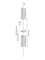
- the terminal 20 receives an activation request from the base station 10 to transmit SRS/receive DL-PRS at a timing when SRS transmission/DL-PRS reception cannot be performed, the terminal 20 sends an activation failure to the base station 10. It is also possible to return it to
- the lower part of FIG. 6 shows an example where activation failure is returned to the base station 10.
- the terminal 20 receives an activation request (indicated by A) from the base station 10 instructing SRS transmission, shown by B, during a certain on-duration.
- the terminal 20 cannot perform the SRS transmission indicated by B, it returns activation failure to the base station 10.
- the terminal 20 may be able to perform SRS transmission/DL-PRS reception during a period outside the DRX on-duration. In other words, it may be possible to perform the operation shown in FIG. For example, in the case shown in the lower part of FIG. 6, when the terminal 20 receives an activation request (indicated by A) instructing SRS transmission shown by B, the terminal 20 temporarily becomes active (wake-up) at timing B. Therefore, SRS transmission/DL-PRS reception may be performed.
- Example 2 On duration timer> Example 2 will be explained using DL-PRS as an example, but it is also applicable to SRS as well.
- DL-PRS is transmitted from multiple base stations (also called TRPs).
- the terminal 20 measures its own position by measuring the received power or time difference of a plurality of DL-PRSs received from a plurality of TRPs.
- the terminal 20 may report the measurement results of a plurality of DL-PRSs to the LMF 30, and the LMF 30 may position the terminal 20.
- the terminal 20 assumes that the on-duration timer is set by the base station 10 in consideration of the expected arrival time width of a plurality of DL-PRSs.
- the on-duration timer indicates the length of time (that is, on-duration) during which the terminal 20 becomes Active in 1 DRX cycle.
- the base station 10 sets an on-duration timer in the terminal 20 in consideration of the expected arrival time width of a plurality of DL-PRS.
- Considering the arrival time width means that DL from at least one (or a predetermined number larger than 1) TRP among the DL-PRS of multiple TRPs configured in the terminal 20. - Refers to being in a state where PRS can be received. That is, Example 2 is an operation for allowing the terminal 20 to receive multiple DL-PRS transmitted from multiple TRPs as reliably as possible. However, it is not essential to receive everything.
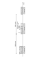
- the terminal 20 receives DL-PRS from three TRPs during an active period (on-duration). As shown in FIG. 7, there are three TRPs: one serving TRP (A) and two non-serving TRPs (B) and (C).
- the three DL-PRSs transmitted from TRPs (A) to (C) arrive at the terminal 20 within the time width T, as shown in FIG.
- the on-duration timer is set from the base station 10 to the terminal 20 so as to include this time width T.
- the period before the on-duration (estimated arrival time) is defined as the preparation period
- the period after the on-duration (estimated arrival time) is defined as the margin time.
- Either or both of the preliminary period and the preliminary period may be set from the base station 10 to the terminal 20.
- the terminal 20 wakes up and monitors signals not only during the on-duration, but also during the preparation period and preliminary period.
- the preparation period may also be referred to as a previous period, an additional active period, or the like.
- the preliminary period may be referred to as a subsequent period, an additional active period, or the like.
- the above arrival time width (eg, relative value (arrival time difference) of the PRS of another TRP with respect to the PRS arrival time of a certain TRP) is notified to the base station 10 from the LMF 30, for example. Further, the above arrival time width may be notified from the LMF 30 to the terminal 20, and the terminal 20 may include it in DRX-related information and notify it to the LMF 30, and the DRX-related information may be notified to the base station 10.
- the base station 10 which has grasped the arrival time width, determines an on-duration timer, preparation period, preliminary period, etc. so that the terminal 20 can receive a predetermined number of DL-PRSs according to the arrival time width.
- the DRX setting information including the information is notified to the terminal 20 by RRC signaling.
- the terminal 20 receives (measures) a plurality of DL-PRSs as shown in FIG. 7 based on the DRX configuration information.
- Example 3 an example using an inactivity timer will be described.
- Example 3 will be explained using DL-PRS as an example, but it is also applicable to SRS as well.
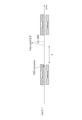
- the terminal 20 starts the inactivity timer when receiving a PDCCH during the DRX wake up period (active period), and extends the wake up period until the inactivity timer expires.
- Example 3 when the terminal 20 receives a positioning signal, it performs the same operation as when it receives a PDCCH. That is, when the terminal 20 receives a positioning signal during the wake up period (active period) of the DRX, it starts the inactivity timer and extends the wake up period until the inactivity timer expires.
- the positioning signal is not limited to a specific signal, but includes, for example, DL-PRS, PDCCH (control signal), PDSCH (data), etc.
- FIG. 8 shows an example of operation when using DL-PRS as a positioning signal.
- the terminal 20 receives the DL-PRS during the active period indicated by A, it operates the inactivity timer and continues the wake up period until the inactivity timer expires. Such operation makes it easier to receive multiple DL-PRSs from multiple TRPs, as described in Example 2.
- the value of the inactivity timer may be determined based on the arrival time width of the DL-PRS.
- the LMF 30 notifies the base station 10 of the arrival time width.
- the base station 10 that has grasped the arrival time width for example, sets the value of the inactivity timer to the same value as the arrival time width or a value larger than the arrival time width, and transmits the DRX configuration information including the set information to the terminal by RRC signaling.
- Notify 20 The terminal 20 performs operations as shown in FIG. 8 based on the DRX setting information.
- the inactivity timer may be set from the NW to the terminal 20 as described above, or a default value may be defined, and the terminal 20 and base station 10 may use the default value.
- the terminal 20 may start the inactivity timer when transmitting a positioning signal during the wake up period (active period) of the DRX, and extend the wake up period until the inactivity timer expires.
- Signals for positioning in UL are not limited to specific signals, but include, for example, SRS, UL-PRS, PUCCH (control signal), PUSCH (data), and the like.
- the terminal 20 can perform a positioning operation with low power consumption. Furthermore, the technology according to the first embodiment has a small spec impact upon introduction.
- the second embodiment may be implemented in combination with any other embodiment, or may be implemented independently of any other embodiment.
- the operation is combined with the operation in the zeroth embodiment. In other words, assume that DRX-related information is being reported to the NW side.
- the terminal 20 assumes that there is a priority order between signal transmission/signal reception for positioning and DRX, and performs operations according to the priority order.
- the following options 1 and 2 are available as operations according to the priority order.
- Option 1 is an example where DRX has a higher priority than positioning.
- the terminal 20 notifies the base station 10 (or LMF 30) that DRX has a higher priority than positioning.
- Options 1-1 and 1-2 will be explained below.
- Option 1-1 and option 1-2 may be implemented in combination.
- Option 1-1 The base station 10 (or LMF 30) transmits/receives signals for positioning during the active period (wake up period) of the terminal 20, for example, based on the DRX cycle and on-duration timer of the terminal 20. Settings for signal transmission/signal reception for positioning are made for the terminal 20 as shown in FIG.
- the terminal 20 when the terminal 20 is configured to transmit/receive signals for positioning without considering the priority between DRX and positioning, DRX has a higher priority than positioning.
- the terminal 20 may request the base station 10 (or the LMF 30) to change the settings for positioning signal transmission/signal reception.
- the base station 10 (or LMF 30) that has received the configuration change request transmits/receives signals for positioning during the active period of the terminal 20, based on the DRX cycle and on-duration timer of the terminal 20, for example.
- Settings (resetting) of signal transmission/signal reception for positioning are performed on the terminal 20 so that the terminal 20 is configured as shown in FIG.
- Option 1-2 If the terminal 20, for which DRX has a higher priority than positioning, receives an activation instruction for corresponding signal transmission/signal reception from the base station 10 during the sleep period, it will return an activation failure to the base station 10. Good too.
- Option 2 is an example where positioning has a higher priority than DRX.
- the terminal 20 notifies the base station 10 (or LMF 30) that positioning has a higher priority than DRX.
- Options 2-1, 2-2, and 2-3 will be explained below. Options 2-1, 2-2, and 2-3 can be implemented in any combination.
- Option 2-1 For example, if the terminal 20 is in the DRX state and has determined that positioning has a higher priority than DRX, it ends the DRX state. Regarding the method of terminating the DRX state, the terminal 20 may request the base station 10 to terminate DRX, or the base station 10 may instruct the terminal 20 to terminate DRX. Note that the terminal 20 may determine that the positioning has a higher priority than the DRX when the positioning is set by the base station 10.
- the terminal 20 may terminate DRX at a timing a predetermined period after the timing at which reconfiguration for terminating DRX is performed from the base station 10. Examples 1 and 2 will be explained as detailed examples.
- Example 1 of how to terminate DRX Assume that a certain time T (T ⁇ 0) [ms] is specified or that a time T (T ⁇ 0) [ms] is set in the terminal 20.
- the terminal 20 terminates DRX after T [ms] from the reconfiguration for terminating DRX.
- the terminal 20 may terminate DRX within T' [ms] after reconfiguration for terminating DRX using a certain time T'(T' ⁇ 0) [ms]. .
- Example 2 (Example 2 of how to terminate DRX) It is assumed that a certain number of slots N (N ⁇ 0) [slots] is specified or that a certain number of slots N (N ⁇ 0) [slots] is set in the terminal 20.
- the terminal 20 terminates DRX after N [slots] from the reconfiguration for terminating DRX.
- the terminal 20 may end DRX within N′ [slots] from reconfiguration for ending DRX.
- Option 2-2 The base station 10 (or LMF 30) controls the DRX cycle and on-duration, for example, so that the terminal 20 transmits/receives signals for positioning during the DRX active period (wake up period) of the terminal 20. Set (or re-set) the DRX settings with timer etc. adjusted on the terminal 20. Furthermore, the terminal 20 may request such setting/resetting from the base station 10 (or LMF 30).
- the terminal 20 in the DRX state may perform positioning signal transmission/signal reception during a period other than the active period (sleep period). That is, as shown in FIG. 3, the terminal 20 may temporarily wake up and perform signal transmission/signal reception operations.
- the terminal 20 determines the priority between DRX and positioning at any timing/frequency among timings (1) to (5) and frequencies (1) to (5) described in the zeroth embodiment. It may also be reported to the base station 10 (or LMF 30).
- the terminal 20 may report the priority between DRX and positioning to the base station 10 (or LMF 30) at the timing when the required positioning frequency changes. For example, the terminal 20 reports priority information indicating that positioning is prioritized over DRX to the base station 10 (or LMF 30) at the timing when its own mode changes from power saving mode to high-frequency positioning mode. do.
- the terminal 20 By reporting the priority between DRX and positioning to the base station 10 (or LMF 30), the terminal 20 selects "DRX", “signal transmission/signal reception for positioning", or "DRX and It may be assumed that the settings of "both signal transmission/signal reception for positioning" are reconfigured from the base station 10.
- the terminal 20 may assume that the priority between DRX and positioning is set by the base station 10 (or LMF 30).
- DRX positioning signal transmission/signal reception
- DRX and positioning The contents of the settings (resettings) for "both signal transmission/signal reception” may implicitly indicate the priority between DRX and positioning. For example, when setting (resetting) is performed so that the operation of option 1 (DRX > positioning) is performed, it is implicitly indicated that DRX has a higher priority than positioning. Furthermore, if the setting (resetting) is made so that the operation of option 2 (positioning > DRX) is performed, it is implicitly shown that positioning has a higher priority than DRX.
- the terminal 20 may assume (determine) different priorities for positioning DL signals (e.g. DL-PRS Rx) and UL signals (SRS Tx), or assume (determine) a common priority. ) may be done. For example, the terminal 20 in the DRX state prioritizes positioning over DRX for DL-PRS, assumes that it receives DL-PRS upon wake up, and receives positioning for UL-SRS. It is assumed that DRX is prioritized over UL-SRS and that it is not transmitted even if the UL-SRS transmission timing arrives in the sleep state.
- DL-PRS Rx DL-PRS Rx
- SRS Tx UL signals
- the technique of the second embodiment described above enables operation that takes into account the trade-off between power consumption and positioning performance.
- the third embodiment may be implemented in combination with any other embodiment, or may be implemented independently of the other embodiments.
- the operation is combined with the operation in the zeroth embodiment. In other words, assume that DRX-related information is being reported to the NW side.
- the base station 10 may detect this and return a positioning activation failure to the LMF 30.
- the terminal 20 assumes that the base station 10 will return positioning activation failure to the LMF 30 if it is unable to transmit/receive signals for positioning at the timing instructed (or set) by the base station 10 (or LMF 30). You may.
- the terminal 20 may also be possible to return positioning activation failure.
- positioning activation failure is an example. Any name of the signal/message may be used as long as the message/signal indicates that positioning signal transmission/signal reception cannot be performed. A message/signal indicating that positioning signal transmission/signal reception cannot be performed may be called "failure.”
- Examples 1 and 2 below are examples of cases in which positioning signal transmission/signal reception cannot be performed at the timing instructed (or set) by the base station 10 (or LMF 30).
- Example 1 A case in which the timing at which positioning signals can be transmitted/received is limited by the DRX settings set from the base station 10 to the terminal 20. In this case, for example, even if the timing for positioning signal transmission/signal reception arrives during the DRX sleep period, the terminal 20 cannot perform the signal transmission/signal reception.
- Example 1 if positioning has a higher priority than DRX, settings are made such that positioning signal transmission/signal reception does not occur during the sleep period, for example. In addition, if positioning has a higher priority than DRX, even if positioning signal transmission/signal reception occurs during the sleep period, the terminal 20 temporarily wakes up and sends/signals the signal. It is also possible to perform reception.
- Example 2 A case where DRX has a higher priority than positioning as described in the second embodiment. In this case, for example, when the timing for positioning signal transmission/signal reception arrives during the DRX sleep period, the terminal 20 cannot perform the signal transmission/signal reception.
- Option 1 the terminal 20 or the base station 10 transmits an activation failure in response to an activation request received by the terminal 20 during the wake up period in the DRX state during the same wake up period.
- FIG. 10 shows an example of option 1.
- the terminal 20 receives an SRS activation instructing to transmit the signal indicated by A during the wake up period, but cannot transmit the signal indicated by A, so the activation failure is transmitted during the wake up period. be done.
- the terminal 20 or base station 10 when the terminal 20 or base station 10 performs signal transmission/signal reception based on the settings without activation during the sleep period, the terminal 20 or the base station 10 performs the wake-up period immediately before the sleep period, as in the case of FIG. Then, failure may be sent to indicate that signal transmission/signal reception is not possible.
- Option 2 the terminal 20 or the base station 10 transmits an activation failure in response to an activation request received by the terminal 20 during the wake up period in the DRX state in the subsequent wake up period.
- the "subsequent wake up period” may be the wake up period immediately following the wake up period in which the activation request was received, or the wake up period immediately after the wake up period in which the activation request was received. It may be an up period.
- the terminal 20 or base station 10 performs signal transmission/signal reception based on settings that does not require activation during the sleep period, the terminal 20 or base station 10 cannot transmit/receive signals during the wake-up period after the sleep period. You may also send a failure message to indicate this.
- the "wake up period after the sleep period" may be the wake up period immediately after the sleep period, or may be the wake up period after the wake up period immediately after the sleep period.
- Option 2-1> In option 2-1, as shown in FIG. 11, if there is no response/failure even after the terminal 20 receives the activation request and the period Determine that failure has been returned for the activation request.
- Option 2-2 is an example of operation in a situation where period X has not yet expired in option 2-1.
- the base station The station 10 may determine that failure has been returned from the terminal 20 by incrementing the timer that counts X and determining that X has expired.
- the terminal 20 after the terminal 20 receives SRS activation in a certain wake-up period, when the activation timing indicated by A has elapsed without transmitting a response/failure, the terminal 20 receives the SRS activation from the base station 10 (or LMF 30). determines that the terminal 20 has returned failure.
- Option 3 ⁇ Activation failure transmission timing: Option 3> In option 3, the terminal 20 wakes up for a short time during the sleep period, and then transitions to the sleep state again after transmitting failure.
- FIG. 13 shows an example of transmitting activation failure in response to SRS activation.
- the terminal 20 assumes that the inactivity timer is not counted depending on the failure transmission. In other words, the terminal 20 transitions to a sleep state immediately after transmitting failure.
- the terminal 20 assumes the time according to the set DRX cycle as the next wake up timing after the wake up period in which the activation request is received. In other words, the terminal 20 does not count the wake up for failure transmission.
- Capability information (UE capability) indicating that the operation of one or more of the zero to third embodiments is supported is defined, and the terminal 20 transmits the capability information to the base station 10. You may report it.
- the base station 10 (or LMF 30) only transmits capability information to the terminal 20 that indicates that it supports the operation of any one or more of the 0th to 3rd embodiments.
- DRX settings/positioning settings according to the supported embodiment may also be performed.
- PRS Positioning Reference Signal
- DL-PRS e.g. SRS for positioning, SRS
- SRS may be read as “SRS for MIMO” or “SRS for positioning.”
- NW may be read as “gNB”, “TRP”, “LMF”, etc.
- Server TRP may be replaced with “reference TRP", etc.
- Configured/indicated by the NW may be read as “configured/activated/indicated by the NW using RRC/MAC-CE/DCI.”
- DRX means “Connected DRX (CDRX/C-DRX)", “Extended DRX (EDRX/E-DRX/ECDRX/E-CDRX)", “Enhanced DRX (EDRX/E-DRX/ECDRX/E- CDRX)”.
- Preparation period and “margin time” may be replaced with “time offset”, “additional time”, etc.
- FIG. 14 is a diagram showing an example of the functional configuration of the base station 10.
- base station 10 includes a transmitting section 110, a receiving section 120, a setting section 130, and a control section 140.
- the functional configuration shown in FIG. 14 is only an example. As long as the operations according to the embodiments of the present invention can be executed, the functional divisions and functional parts may have any names.
- the transmitting section 110 and the receiving section 120 may be collectively referred to as a communication section.
- the transmitting unit 110 includes a function of generating a signal to be transmitted to the terminal 20 side and transmitting the signal wirelessly.
- the transmitter 110 can also transmit a signal to a network device such as the LMF 30.
- the receiving unit 120 includes a function of receiving various signals transmitted from the terminal 20 and acquiring, for example, information on a higher layer from the received signals.
- the receiving unit 120 can also receive signals from a network device such as the LMF 30.
- the transmitter 110 has a function of transmitting NR-PSS, NR-SSS, NR-PBCH, DL/UL control signals, DCI using PDCCH, data using PDSCH, etc. to the terminal 20.
- the setting unit 130 stores preset setting information and various setting information to be sent to the terminal 20 in a storage device included in the setting unit 130, and reads them from the storage device as necessary.
- the control unit 140 schedules DL reception or UL transmission of the terminal 20 via the transmission unit 110. Further, the control unit 140 includes a function to perform LBT. A functional unit related to signal transmission in the control unit 140 may be included in the transmitting unit 110, and a functional unit related to signal reception in the control unit 140 may be included in the receiving unit 120. Further, the transmitting section 110 may be called a transmitter, and the receiving section 120 may be called a receiver.
- the LMF 30 may also have the configuration shown in FIG. 14.
- the transmitter 110 transmits signals to other network devices (including base stations), and the receiver 120 receives signals from other network devices (including base stations). do.
- FIG. 15 is a diagram showing an example of the functional configuration of the terminal 20.
- the terminal 20 includes a transmitting section 210, a receiving section 220, a setting section 230, and a control section 240.
- the functional configuration shown in FIG. 15 is only an example. As long as the operations according to the embodiments of the present invention can be executed, the functional divisions and functional parts may have any names.
- the transmitting section 210 and the receiving section 220 may be collectively referred to as a communication section.
- the transmitter 210 creates a transmission signal from the transmission data and wirelessly transmits the transmission signal.
- the receiving unit 220 wirelessly receives various signals and obtains higher layer signals from the received physical layer signals. Further, the receiving unit 220 has a function of receiving NR-PSS, NR-SSS, NR-PBCH, DL/UL/SL control signals, DCI by PDCCH, data by PDSCH, etc. transmitted from the base station 10.
- the transmitting unit 210 transmits a PSCCH (Physical Sidelink Control Channel), a PSSCH (Physical Sidelink Shared Channel), a PSDCH to another terminal 20 as D2D communication.
- PSCCH Physical Sidelink Control Channel
- PSSCH Physical Sidelink Shared Channel
- PSDCH Physical Sidelink Shared Channel
- the receiving unit 220 may receive the PSCCH, PSSCH, PSDCH, PSBCH, etc. from the other terminal 20. Further, the transmitter 210 includes the antenna port described in this embodiment.
- the setting unit 230 stores various types of setting information received from the base station 10 or other terminals by the receiving unit 220 in a storage device included in the setting unit 230, and reads the information from the storage device as necessary.
- the setting unit 230 also stores setting information that is set in advance.
- the control unit 240 controls the terminal 20.
- a functional unit related to signal transmission in the control unit 240 may be included in the transmitting unit 210, and a functional unit related to signal reception in the control unit 240 may be included in the receiving unit 220.
- the transmitter 210 may be called a transmitter, and the receiver 220 may be called a receiver.
- At least the following terminals and base stations are provided.
- Additional note 1 (Additional note 1) a transmitter that transmits information regarding intermittent reception to the network; a control unit that assumes transmitting or receiving signals for positioning in accordance with the timing of intermittent reception; A terminal equipped with (Additional note 2) a transmitter that transmits information regarding intermittent reception to the network; a control unit that assumes intermittent reception in accordance with the timing of signal transmission or signal reception for positioning; A terminal equipped with (Additional note 3) The terminal according to supplementary note 1 or 2, wherein the control unit controls the terminal to transmit or receive a signal for positioning at the period of the intermittent reception.
- Any of Items 1 to 6 provides a technique that allows a terminal that performs intermittent reception to appropriately transmit or receive signals for positioning. According to additional items 3, 4, and 5, the terminal can appropriately transmit or receive signals for positioning.
- Additional note 2 a control unit that assumes a priority order between intermittent reception and signal transmission or signal reception for positioning; and a communication unit configured to perform signal transmission or signal reception for positioning in an intermittent reception state according to the priority order.
- the communication unit receives a setting change regarding the positioning from a network, or transmits the setting change to the network so that the signal transmission or signal reception for the positioning is performed during the wake-up period in the intermittent reception. Request the terminal described in Supplementary Note 1.
- Supplementary Note 1 When the priority of the intermittent reception is higher than the priority of the signal transmission or signal reception for positioning, Supplementary Note 1: When the communication unit is unable to transmit or receive a signal for positioning, the communication unit transmits a message to the network indicating that the signal transmission or reception for positioning is not possible. Or the terminal described in 2. (Additional note 4) When the priority of the intermittent reception is lower than the priority of the signal transmission or signal reception for positioning, The terminal according to any one of Supplementary Notes 1 to 3, wherein the communication unit terminates the intermittent reception state in response to a request to the network or an instruction from the network.
- the communication unit receives a setting change related to the intermittent reception from a network, or transmits the setting change to the network so that the signal transmission or signal reception for positioning is performed during the wake-up period in the intermittent reception.
- Required A terminal described in any one of Supplementary Notes 1 to 4.
- a control unit that assumes a priority order between intermittent reception and signal transmission or signal reception for positioning; Depending on the priority, a setting change is transmitted to the terminal so that the signal transmission or signal reception for positioning is performed at the terminal during the wake-up period in the intermittent reception, or the setting change is changed. and a communication unit that receives a request from the terminal.
- Any of Items 1 to 6 provides a technique that allows a terminal that performs intermittent reception to appropriately transmit or receive signals for positioning. According to additional notes 2, 3, 4, and 5, operations can be appropriately executed according to the priority order.
- Additional note 3 (Additional note 1) a communication unit that determines that it is not possible to transmit or receive signals for positioning due to limitations in signal transmission and reception timing in the intermittent reception state; a control unit that assumes that a message indicating that the signal transmission or the signal reception is not possible is transmitted from the base station to the network device; A terminal equipped with (Additional note 2) a control unit that determines that in an intermittent reception state, signal transmission or signal reception for positioning cannot be performed due to limitations on signal transmission/reception timing; a transmitting unit that transmits a message to a network indicating that the signal transmission or the signal reception is not possible; A terminal equipped with (Additional note 3) When the terminal receives an instruction regarding the signal transmission or the signal reception during a wake-up period, the transmitter transmits the message during the wake-up period or a wake-up period subsequent to the wake-up period.
- the terminal described in Supplementary Note 2. (Additional note 4) The terminal according to supplementary note 2, wherein the transmitter temporarily wakes up during a sleep period and transmits the message. (Additional note 5) If the message is not transmitted from the terminal for a predetermined period after the instruction regarding the signal transmission or the signal reception is transmitted from the network to the terminal, the network determines that the terminal has transmitted the message. A terminal described in any one of Supplementary Notes 2 to 4.
- a control unit that determines that, when the terminal is in an intermittent reception state, the terminal is unable to transmit or receive signals for positioning due to limitations on signal transmission/reception timing; a transmitting unit that transmits a message indicating that the signal transmission or the signal reception is not possible to the network device;
- a base station equipped with
- Any of Items 1 to 6 provides a technique that allows a terminal that performs intermittent reception to appropriately transmit or receive signals for positioning. According to additional notes 3, 4, and 5, the network side can appropriately determine that the terminal was unable to transmit or receive a signal for positioning.
- each functional block may be realized using one physically or logically coupled device, or may be realized using two or more physically or logically separated devices directly or indirectly (e.g. , wired, wireless, etc.) and may be realized using a plurality of these devices.
- the functional block may be realized by combining software with the one device or the plurality of devices.
- Functions include judgment, decision, judgment, calculation, calculation, processing, derivation, investigation, exploration, confirmation, reception, transmission, output, access, resolution, selection, selection, establishment, comparison, assumption, expectation, consideration, These include, but are not limited to, broadcasting, notifying, communicating, forwarding, configuring, reconfiguring, allocating, mapping, and assigning. I can't do it.
- a functional block (configuration unit) that performs transmission is called a transmitting unit or a transmitter. In either case, as described above, the implementation method is not particularly limited.
- the base station 10, terminal 20, etc. in an embodiment of the present disclosure may function as a computer that performs processing of the wireless communication method of the present disclosure.
- FIG. 16 is a diagram illustrating an example of the hardware configuration of the base station 10, the terminal 20, and the LMF 30 according to an embodiment of the present disclosure.
- the base station 10 and terminal 20 described above are physically configured as a computer device including a processor 1001, a storage device 1002, an auxiliary storage device 1003, a communication device 1004, an input device 1005, an output device 1006, a bus 1007, etc. Good too.
- the word “apparatus” can be read as a circuit, a device, a unit, etc.
- the hardware configuration of the base station 10 and the terminal 20 may be configured to include one or more of each device shown in the figure, or may be configured not to include some of the devices.
- Each function in the base station 10 and the terminal 20 is performed by loading predetermined software (programs) onto hardware such as the processor 1001 and the storage device 1002, so that the processor 1001 performs calculations and controls communication by the communication device 1004. This is realized by controlling at least one of reading and writing data in the storage device 1002 and the auxiliary storage device 1003.
- the processor 1001 for example, operates an operating system to control the entire computer.
- the processor 1001 may be configured with a central processing unit (CPU) that includes interfaces with peripheral devices, a control device, an arithmetic device, registers, and the like.
- CPU central processing unit
- control unit 140, control unit 240, etc. may be implemented by the processor 1001.
- the processor 1001 reads programs (program codes), software modules, data, etc. from at least one of the auxiliary storage device 1003 and the communication device 1004 to the storage device 1002, and executes various processes in accordance with these.
- programs program codes
- the control unit 140 of the base station 10 shown in FIG. 14 may be realized by a control program stored in the storage device 1002 and operated on the processor 1001.
- the control unit 240 of the terminal 20 shown in FIG. 15 may be realized by a control program stored in the storage device 1002 and operated on the processor 1001.
- Processor 1001 may be implemented by one or more chips. Note that the program may be transmitted from a network via a telecommunications line.
- the storage device 1002 is a computer-readable recording medium, such as at least one of ROM (Read Only Memory), EPROM (Erasable Programmable ROM), EEPROM (Electrically Erasable Programmable ROM), RAM (Random Access Memory), etc. may be configured.
- the storage device 1002 may be called a register, cache, main memory, or the like.
- the storage device 1002 can store executable programs (program codes), software modules, and the like to implement a communication method according to an embodiment of the present disclosure.
- the auxiliary storage device 1003 is a computer-readable recording medium, such as an optical disk such as a CD-ROM (Compact Disc ROM), a hard disk drive, a flexible disk, a magneto-optical disk (for example, a compact disk, a digital versatile disk, a Blu-ray disk, etc.). -ray disk), smart card, flash memory (eg, card, stick, key drive), floppy disk, magnetic strip, etc.
- the above-mentioned storage medium may be, for example, a database including at least one of the storage device 1002 and the auxiliary storage device 1003, a server, or other suitable medium.
- the communication device 1004 is hardware (transmission/reception device) for communicating between computers via at least one of a wired network and a wireless network, and is also referred to as a network device, network controller, network card, communication module, etc., for example.
- the communication device 1004 includes, for example, a high frequency switch, a duplexer, a filter, a frequency synthesizer, etc. in order to realize at least one of frequency division duplex (FDD) and time division duplex (TDD). It may be composed of.
- FDD frequency division duplex
- TDD time division duplex
- the transmitting and receiving unit may be physically or logically separated into a transmitting unit and a receiving unit.
- the input device 1005 is an input device (eg, keyboard, mouse, microphone, switch, button, sensor, etc.) that accepts input from the outside.
- the output device 1006 is an output device (for example, a display, a speaker, an LED lamp, etc.) that performs output to the outside. Note that the input device 1005 and the output device 1006 may have an integrated configuration (for example, a touch panel).
- each device such as the processor 1001 and the storage device 1002 is connected by a bus 1007 for communicating information.
- the bus 1007 may be configured using a single bus, or may be configured using different buses for each device.
- the base station 10, the terminal 20, and the LMF 30 are equipped with a microprocessor, a digital signal processor (DSP), an application specific integrated circuit (ASIC), a programmable logic device (PLD), a field programmable gate array (FPGA), etc. It may be configured to include hardware, and a part or all of each functional block may be realized by the hardware. For example, processor 1001 may be implemented using at least one of these hardwares.
- DSP digital signal processor
- ASIC application specific integrated circuit
- PLD programmable logic device
- FPGA field programmable gate array
- the vehicle 2001 may be equipped with the terminal 20, the base station 10, or the LMF 30.
- FIG. 17 shows an example of the configuration of vehicle 2001.
- the vehicle 2001 includes a drive unit 2002, a steering unit 2003, an accelerator pedal 2004, a brake pedal 2005, a shift lever 2006, a front wheel 2007, a rear wheel 2008, an axle 2009, an electronic control unit 2010, and various sensors 2021 to 2029. , an information service section 2012 and a communication module 2013.
- the terminal 20 or base station 10 according to each aspect/embodiment described in this disclosure may be applied to a communication device mounted on the vehicle 2001, for example, may be applied to the communication module 2013.
- the drive unit 2002 is composed of, for example, an engine, a motor, or a hybrid of an engine and a motor.
- the steering unit 2003 includes at least a steering wheel (also referred to as a steering wheel), and is configured to steer at least one of the front wheels and the rear wheels based on the operation of the steering wheel operated by the user.
- the electronic control unit 2010 is composed of a microprocessor 2031, memory (ROM, RAM) 2032, and communication port (IO port) 2033. Signals from various sensors 2021 to 2029 provided in the vehicle 2001 are input to the electronic control unit 2010.
- the electronic control unit 2010 may also be called an ECU (Electronic Control Unit).
- Signals from various sensors 2021 to 2029 include a current signal from a current sensor 2021 that senses the motor current, a front wheel and rear wheel rotation speed signal obtained by a rotation speed sensor 2022, and a front wheel rotation speed signal obtained by an air pressure sensor 2023. and rear wheel air pressure signals, vehicle speed signals acquired by vehicle speed sensor 2024, acceleration signals acquired by acceleration sensor 2025, accelerator pedal depression amount signals acquired by accelerator pedal sensor 2029, and brake pedal sensor 2026. These include a brake pedal depression amount signal, a shift lever operation signal acquired by the shift lever sensor 2027, a detection signal for detecting obstacles, vehicles, pedestrians, etc. acquired by the object detection sensor 2028, and the like.
- the information service department 2012 controls various devices such as car navigation systems, audio systems, speakers, televisions, and radios that provide (output) various information such as driving information, traffic information, and entertainment information, and these devices. It is composed of one or more ECUs.
- the information service unit 2012 provides various multimedia information and multimedia services to the occupants of the vehicle 2001 using information acquired from an external device via the communication module 2013 and the like.
- the information service department 2012 may include an input device (for example, a keyboard, a mouse, a microphone, a switch, a button, a sensor, a touch panel, etc.) that accepts input from the outside, and an output device that performs output to the outside (for example, display, speaker, LED lamp, touch panel, etc.).
- the driving support system unit 2030 includes a millimeter wave radar, LiDAR (Light Detection and Ranging), a camera, a positioning locator (for example, GNSS, etc.), map information (for example, a high-definition (HD) map, an autonomous vehicle (AV) map, etc.) ), gyro systems (e.g., IMU (Inertial Measurement Unit), INS (Inertial Navigation System), etc.), AI (Artificial Intelligence) chips, and AI processors that prevent accidents and reduce the driver's driving burden.
- the system is comprised of various devices that provide functions for the purpose and one or more ECUs that control these devices. Further, the driving support system unit 2030 transmits and receives various information via the communication module 2013, and realizes a driving support function or an automatic driving function.
- Communication module 2013 can communicate with microprocessor 2031 and components of vehicle 2001 via a communication port.
- the communication module 2013 communicates with the drive unit 2002, steering unit 2003, accelerator pedal 2004, brake pedal 2005, shift lever 2006, front wheels 2007, rear wheels 2008, axle 2009, electronic Data is transmitted and received between the microprocessor 2031, memory (ROM, RAM) 2032, and sensors 2021 to 29 in the control unit 2010.
- the communication module 2013 is a communication device that can be controlled by the microprocessor 2031 of the electronic control unit 2010 and can communicate with external devices. For example, various information is transmitted and received with an external device via wireless communication.
- the communication module 2013 may be located either inside or outside the electronic control unit 2010.
- the external device may be, for example, a base station, a mobile station, or the like.
- the communication module 2013 receives signals from the various sensors 2021 to 2028 described above that are input to the electronic control unit 2010, information obtained based on the signals, and input from the outside (user) obtained via the information service unit 2012. At least one of the information based on the information may be transmitted to an external device via wireless communication.
- the electronic control unit 2010, various sensors 2021-2028, information service unit 2012, etc. may be called an input unit that receives input.
- the PUSCH transmitted by the communication module 2013 may include information based on the above input.
- the communication module 2013 receives various information (traffic information, signal information, inter-vehicle information, etc.) transmitted from an external device, and displays it on the information service section 2012 provided in the vehicle 2001.
- the information service unit 2012 is an output unit that outputs information (for example, outputs information to devices such as a display and a speaker based on the PDSCH (or data/information decoded from the PDSCH) received by the communication module 2013). may be called.
- Communication module 2013 also stores various information received from external devices into memory 2032 that can be used by microprocessor 2031 . Based on the information stored in the memory 2032, the microprocessor 2031 controls the drive section 2002, steering section 2003, accelerator pedal 2004, brake pedal 2005, shift lever 2006, front wheel 2007, rear wheel 2008, and axle 2009 provided in the vehicle 2001. , sensors 2021 to 2029, etc. may be controlled.
- the operations of a plurality of functional sections may be physically performed by one component, or the operations of one functional section may be physically performed by a plurality of components.
- the order of processing may be changed as long as there is no contradiction.
- Software operated by the processor included in the base station 10 according to the embodiment of the present invention and software operated by the processor included in the terminal 20 according to the embodiment of the present invention are respectively random access memory (RAM), flash memory, and read-only memory. (ROM), EPROM, EEPROM, register, hard disk (HDD), removable disk, CD-ROM, database, server, or any other suitable storage medium.
- the notification of information is not limited to the aspects/embodiments described in this disclosure, and may be performed using other methods.
- the notification of information may be physical layer signaling (e.g., DCI (Downlink Control Information), UCI (Uplink Control Information)), upper layer signaling (e.g., RRC (Radio Resource Control) signaling, MAC (Medium Access Control) signaling). , broadcast information (MIB (Master Information Block), SIB (System Information Block)), other signals, or a combination thereof.
- RRC signaling may be called an RRC message, and may be, for example, an RRC Connection Setup message, an RRC Connection Reconfiguration message, or the like.
- Each aspect/embodiment described in this disclosure is LTE (Long Term Evolution), LTE-A (LTE-Advanced), SUPER 3G, IMT-Advanced, 4G (4th generation mobile communication system), 5G (5th generation mobile communication system). system), 6th generation mobile communication system (6G), xth generation mobile communication system (xG) (xG (x is an integer or decimal number, for example)), FRA (Future Radio Access), NR (new Radio), New radio access ( NX), Future generation radio access (FX), W-CDMA (registered trademark), GSM (registered trademark), CDMA2000, UMB (Ultra Mobile Broadband), IEEE 802.11 (Wi-Fi (registered trademark)), IEEE 802 Systems that utilize .16 (WiMAX (registered trademark)), IEEE 802.20, UWB (Ultra-WideBand), Bluetooth (registered trademark), and other appropriate systems, and that are extended, modified, created, and defined based on these.
- the present invention may be
- the base station 10 may be performed by its upper node in some cases.
- various operations performed for communication with a terminal 20 are performed by the base station 10 and other network nodes other than the base station 10. It is clear that this can be done by at least one of the following: for example, MME or S-GW (possible, but not limited to).
- MME Mobility Management Entity
- S-GW Packet Control Function
- the other network node may be a combination of multiple other network nodes (for example, MME and S-GW).
- the information, signals, etc. described in this disclosure can be output from an upper layer (or lower layer) to a lower layer (or upper layer). It may be input/output via multiple network nodes.
- the input/output information may be stored in a specific location (for example, memory) or may be managed using a management table. Information etc. to be input/output may be overwritten, updated, or additionally written. The output information etc. may be deleted. The input information etc. may be transmitted to other devices.
- the determination in the present disclosure may be performed based on a value represented by 1 bit (0 or 1), a truth value (Boolean: true or false), or a comparison of numerical values (e.g. , comparison with a predetermined value).
- Software includes instructions, instruction sets, code, code segments, program code, programs, subprograms, software modules, whether referred to as software, firmware, middleware, microcode, hardware description language, or by any other name. , should be broadly construed to mean an application, software application, software package, routine, subroutine, object, executable, thread of execution, procedure, function, etc.
- software, instructions, information, etc. may be sent and received via a transmission medium.
- a transmission medium For example, if the software uses wired technology (coaxial cable, fiber optic cable, twisted pair, digital subscriber line (DSL), etc.) and/or wireless technology (infrared, microwave, etc.) to create a website, When transmitted from a server or other remote source, these wired and/or wireless technologies are included within the definition of transmission medium.
- wired technology coaxial cable, fiber optic cable, twisted pair, digital subscriber line (DSL), etc.
- wireless technology infrared, microwave, etc.
- data, instructions, commands, information, signals, bits, symbols, chips, etc. which may be referred to throughout the above description, may refer to voltages, currents, electromagnetic waves, magnetic fields or magnetic particles, light fields or photons, or any of these. It may also be represented by a combination of
- At least one of the channel and the symbol may be a signal.
- the signal may be a message.
- a component carrier may also be called a carrier frequency, a cell, a frequency carrier, or the like.
- system and “network” are used interchangeably.
- radio resources may be indicated by an index.
- Base Station BS
- wireless base station base station
- base station fixed station
- NodeB eNodeB
- gNodeB gNodeB
- a base station can accommodate one or more (eg, three) cells. If a base station accommodates multiple cells, the overall coverage area of the base station can be partitioned into multiple smaller areas, and each smaller area is divided into multiple subsystems (e.g., small indoor base stations (RRHs)). Communication services can also be provided by Remote Radio Head).
- RRHs small indoor base stations
- Communication services can also be provided by Remote Radio Head).
- the term "cell” or “sector” refers to part or all of the coverage area of a base station and/or base station subsystem that provides communication services in this coverage.
- the base station transmitting information to the terminal may be read as the base station instructing the terminal to control/operate based on the information.
- MS Mobile Station
- UE User Equipment
- a mobile station is defined by a person skilled in the art as a subscriber station, mobile unit, subscriber unit, wireless unit, remote unit, mobile device, wireless device, wireless communication device, remote device, mobile subscriber station, access terminal, mobile terminal, wireless It may also be referred to as a terminal, remote terminal, handset, user agent, mobile client, client, or some other suitable terminology.
- At least one of a base station and a mobile station may be called a transmitting device, a receiving device, a communication device, etc.
- the base station and the mobile station may be a device mounted on a mobile body, the mobile body itself, or the like.
- the moving body refers to a movable object, and the moving speed is arbitrary. Naturally, this also includes cases where the moving object is stopped.
- the mobile objects include, for example, vehicles, transport vehicles, automobiles, motorcycles, bicycles, connected cars, excavators, bulldozers, wheel loaders, dump trucks, forklifts, trains, buses, carts, rickshaws, ships and other watercraft.
- the mobile object may be a mobile object that autonomously travels based on a travel command. It may be a vehicle (e.g. car, airplane, etc.), an unmanned moving object (e.g. drone, self-driving car, etc.), or a robot (manned or unmanned). good.
- the base station and the mobile station includes devices that do not necessarily move during communication operations.
- at least one of the base station and the mobile station may be an IoT (Internet of Things) device such as a sensor.
- IoT Internet of Things
- the base station in the present disclosure may be replaced by a terminal.
- a configuration in which communication between a base station and a terminal is replaced with communication between a plurality of terminals 20 for example, it may be called D2D (Device-to-Device), V2X (Vehicle-to-Everything), etc.)
- the terminal 20 may have the functions that the base station 10 described above has.
- words such as "up” and “down” may be replaced with words corresponding to inter-terminal communication (for example, "side”).
- uplink channels, downlink channels, etc. may be replaced with side channels.
- a terminal in the present disclosure may be replaced by a base station.
- a configuration may be adopted in which the base station has the functions that the above-described terminal has.
- determining may encompass a wide variety of operations.
- “Judgment” and “decision” include, for example, judging, calculating, computing, processing, deriving, investigating, looking up, search, and inquiry. (e.g., searching in a table, database, or other data structure), and regarding an ascertaining as a “judgment” or “decision.”
- judgment and “decision” refer to receiving (e.g., receiving information), transmitting (e.g., sending information), input, output, and access.
- (accessing) may include considering something as a “judgment” or “decision.”
- judgment and “decision” refer to resolving, selecting, choosing, establishing, comparing, etc. as “judgment” and “decision”. may be included.
- judgment and “decision” may include regarding some action as having been “judged” or “determined.”
- judgment (decision) may be read as “assuming", “expecting", “considering”, etc.
- connection refers to any connection or coupling, direct or indirect, between two or more elements and to each other. It may include the presence of one or more intermediate elements between two elements that are “connected” or “coupled.”
- the bonds or connections between elements may be physical, logical, or a combination thereof. For example, "connection” may be replaced with "access.”
- two elements may include one or more electrical wires, cables, and/or printed electrical connections, as well as in the radio frequency domain, as some non-limiting and non-inclusive examples. , electromagnetic energy having wavelengths in the microwave and optical (both visible and non-visible) ranges.
- the reference signal can also be abbreviated as RS (Reference Signal), and may be called a pilot depending on the applied standard.
- RS Reference Signal
- the phrase “based on” does not mean “based solely on” unless explicitly stated otherwise. In other words, the phrase “based on” means both “based only on” and “based at least on.”
- any reference to elements using the designations "first,” “second,” etc. does not generally limit the amount or order of those elements. These designations may be used in this disclosure as a convenient way to distinguish between two or more elements. Thus, reference to a first and second element does not imply that only two elements may be employed or that the first element must precede the second element in any way.
- a radio frame may be composed of one or more frames in the time domain. Each frame or frames in the time domain may be called a subframe. A subframe may also be composed of one or more slots in the time domain. A subframe may have a fixed time length (eg, 1 ms) that does not depend on numerology.
- the numerology may be a communication parameter applied to the transmission and/or reception of a certain signal or channel. Numerology includes, for example, subcarrier spacing (SCS), bandwidth, symbol length, cyclic prefix length, transmission time interval (TTI), number of symbols per TTI, radio frame configuration, and transmitter/receiver. It may also indicate at least one of a specific filtering process performed in the frequency domain, a specific windowing process performed by the transceiver in the time domain, and the like.
- SCS subcarrier spacing
- TTI transmission time interval
- transmitter/receiver transmitter/receiver. It may also indicate at least one of a specific filtering process performed in the frequency domain, a specific windowing process performed by the transceiver in the time domain, and the like.
- a slot may be composed of one or more symbols (OFDM (Orthogonal Frequency Division Multiplexing) symbols, SC-FDMA (Single Carrier Frequency Division Multiple Access) symbols, etc.) in the time domain.
- a slot may be a unit of time based on numerology.
- a slot may include multiple mini-slots. Each minislot may be made up of one or more symbols in the time domain. Furthermore, a mini-slot may also be called a sub-slot. A minislot may be made up of fewer symbols than a slot.
- PDSCH (or PUSCH) transmitted in time units larger than minislots may be referred to as PDSCH (or PUSCH) mapping type A.
- PDSCH (or PUSCH) transmitted using minislots may be referred to as PDSCH (or PUSCH) mapping type B.
- Radio frames, subframes, slots, minislots, and symbols all represent time units when transmitting signals. Other names may be used for the radio frame, subframe, slot, minislot, and symbol.
- one subframe may be called a transmission time interval (TTI)
- TTI transmission time interval
- multiple consecutive subframes may be called a TTI
- one slot or one minislot may be called a TTI. It's okay.
- at least one of the subframe and TTI may be a subframe (1ms) in existing LTE, a period shorter than 1ms (for example, 1-13 symbols), or a period longer than 1ms. It may be.
- the unit representing the TTI may be called a slot, minislot, etc. instead of a subframe.
- one slot may be called a unit time. The unit time may be different for each cell depending on the numerology.
- TTI refers to, for example, the minimum time unit for scheduling in wireless communication.
- a base station performs scheduling to allocate radio resources (frequency bandwidth, transmission power, etc. that can be used by each terminal 20) to each terminal 20 on a TTI basis.
- radio resources frequency bandwidth, transmission power, etc. that can be used by each terminal 20
- TTI is not limited to this.
- the TTI may be a transmission time unit of a channel-coded data packet (transport block), a code block, a codeword, etc., or may be a processing unit of scheduling, link adaptation, etc. Note that when a TTI is given, the time interval (for example, the number of symbols) to which transport blocks, code blocks, code words, etc. are actually mapped may be shorter than the TTI.
- one slot or one minislot is called a TTI
- one or more TTIs may be the minimum time unit for scheduling.
- the number of slots (minislot number) that constitutes the minimum time unit of the scheduling may be controlled.
- a TTI having a time length of 1 ms may be called a normal TTI (TTI in LTE Rel. 8-12), normal TTI, long TTI, normal subframe, normal subframe, long subframe, slot, etc.
- TTI that is shorter than the normal TTI may be referred to as an abbreviated TTI, short TTI, partial or fractional TTI, shortened subframe, short subframe, minislot, subslot, slot, etc.
- long TTI for example, normal TTI, subframe, etc.
- short TTI for example, short TTI, etc. It may also be read as a TTI having the above TTI length.
- a resource block is a resource allocation unit in the time domain and frequency domain, and may include one or more continuous subcarriers in the frequency domain.
- the number of subcarriers included in an RB may be the same regardless of the numerology, and may be 12, for example.
- the number of subcarriers included in an RB may be determined based on newerology.
- the time domain of an RB may include one or more symbols, and may be one slot, one minislot, one subframe, or one TTI in length.
- One TTI, one subframe, etc. may each be composed of one or more resource blocks.
- one or more RBs include physical resource blocks (PRBs), sub-carrier groups (SCGs), resource element groups (REGs), PRB pairs, RB pairs, etc. May be called.
- PRBs physical resource blocks
- SCGs sub-carrier groups
- REGs resource element groups
- PRB pairs RB pairs, etc. May be called.
- a resource block may be configured by one or more resource elements (REs).
- REs resource elements
- 1 RE may be a radio resource region of 1 subcarrier and 1 symbol.
- a bandwidth part (which may also be called a partial bandwidth or the like) may represent a subset of consecutive common resource blocks (RBs) for a certain numerology in a certain carrier.
- the common RB may be specified by an RB index based on a common reference point of the carrier.
- PRBs may be defined in a BWP and numbered within that BWP.
- the BWP may include a UL BWP (UL BWP) and a DL BWP (DL BWP).
- UL BWP UL BWP
- DL BWP DL BWP
- One or more BWPs may be configured within one carrier for a UE.
- At least one of the configured BWPs may be active and the UE may not expect to transmit or receive a given signal/channel outside of the active BWP.
- “cell”, “carrier”, etc. in the present disclosure may be replaced with "BWP”.
- radio frames, subframes, slots, minislots, symbols, etc. described above are merely examples.
- the number of subframes included in a radio frame, the number of slots per subframe or radio frame, the number of minislots included in a slot, the number of symbols and RBs included in a slot or minislot, the number of symbols included in an RB, Configurations such as the number of subcarriers, the number of symbols in a TTI, the symbol length, and the cyclic prefix (CP) length can be changed in various ways.
- a and B are different may mean “A and B are different from each other.” Note that the term may also mean that "A and B are each different from C”. Terms such as “separate” and “coupled” may also be interpreted similarly to “different.”
- notification of prescribed information is not limited to being done explicitly, but may also be done implicitly (for example, not notifying the prescribed information). Good too.
- Base station 110 Transmitting section 120 Receiving section 130 Setting section 140 Control section 20 Terminal 210 Transmitting section 220 Receiving section 230 Setting section 240 Control section 1001 Processor 1002 Storage device 1003 Auxiliary storage device 1004 Communication device 1005 Input device 1006 Output device 2001 Vehicle 2002 Driving part 2003 Restoration Part 2004 Axel Pedal 2005 Brake Pedal 2006 Shift Lever 2007 Front wheels 2008 Bearing 2009 Axis 2010 Electronic Control Division 2012 Electronic Control Division 20133 Communication Modular 2021 Current sensor 2022 Round Sensor 2023 Air pressure sensor 2024 vehicle speed Sensen Sa 2025 acceleration sensor 2026 brake Pedal sensor 2027 Shift lever sensor 2028 Object detection sensor 2029 Accelerator pedal sensor 2030 Driving support system section 2031 Microprocessor 2032 Memory (ROM, RAM) 2033 Communication port (IO port)
Landscapes
- Engineering & Computer Science (AREA)
- Computer Networks & Wireless Communication (AREA)
- Signal Processing (AREA)
- Mobile Radio Communication Systems (AREA)
Abstract
端末において、間欠受信に関する情報をネットワークに送信する送信部と、間欠受信のタイミングに合わせて、位置測位のための信号送信又は信号受信を行うことを想定する制御部と、を備える端末。
Description
本発明は、無線通信システムにおける端末、及び基地局に関する。
LTE(Long Term Evolution)の後継システムであるNR(New Radio)(「5G」ともいう。)においては、要求条件として、大容量のシステム、高速なデータ伝送速度、低遅延、多数の端末の同時接続、低コスト、省電力等を満たす技術が検討されている(例えば非特許文献1)。
NRにおいては、端末の省電力化を図るために、端末がネットワークからのページングメッセージの受信を周期的に試みる間欠受信(DRX;Discontinuous Reception)動作が規定されている(例えば非特許文献2)。
3GPP TS 38.300 V16.6.0 (2021-07)
3GPP TS 38.321 V16.5.0 (2021-07)
リリース18NRでは、能力低減された端末であるRedCap UE向けの位置測位拡張が検討されており、位置測位の省電力化が議論される予定である。
しかしながら、従来技術(例えばリリース17NR位置測位)では、間欠受信(DRX)動作を考慮した位置測位機能は規定されていない。間欠受信(DRX)動作が設定されている端末は、適切に位置測位のための信号送信又は信号受信を実施できない可能性がある。
本発明は上記の点に鑑みてなされたものであり、間欠受信動作を行う端末が、適切に位置測位のための信号送信又は信号受信を行うことを可能とする技術を提供することを目的とする。
開示の技術によれば、間欠受信に関する情報をネットワークに送信する送信部と、
間欠受信のタイミングに合わせて、位置測位のための信号送信又は信号受信を行うことを想定する制御部と、
を備える端末が提供される。
間欠受信のタイミングに合わせて、位置測位のための信号送信又は信号受信を行うことを想定する制御部と、
を備える端末が提供される。
開示の技術によれば、間欠受信動作を行う端末が、適切に位置測位のための信号送信又は信号受信を行うことを可能とする技術が提供される。
以下、図面を参照して本発明の実施の形態を説明する。なお、以下で説明する実施の形態は一例であり、本発明が適用される実施の形態は、以下の実施の形態に限られない。
本発明の実施の形態の無線通信システムの動作にあたっては、適宜、既存技術が使用される。ただし、当該既存技術は、例えば既存のLTEあるいは既存のNRであるが、既存のLTE、NRに限られない。
また、以下で説明する本発明の実施の形態では、既存のLTEあるいはNRで使用されているSS(Synchronization signal)、PSS(Primary SS)、SSS(Secondary SS)、PBCH(Physical broadcast channel)、PRACH(Physical random access channel)、PDCCH(Physical Downlink Control Channel)、PDSCH(Physical Downlink Shared Channel)、PUCCH(Physical Uplink Control Channel)、PUSCH(Physical Uplink Shared Channel)等の用語を使用する。これは記載の便宜上のためであり、これらと同様の信号、機能等が他の名称で呼ばれてもよい。また、NRにおける上述の用語は、NR-SS、NR-PSS、NR-SSS、NR-PBCH、NR-PRACH等に対応する。ただし、NRに使用される信号であっても、必ずしも「NR-」と明記しない。
また、本発明の実施の形態において、複信(Duplex)方式は、TDD(Time Division Duplex)方式でもよいし、FDD(Frequency Division Duplex)方式でもよいし、又はそれ以外(例えば、Flexible Duplex等)の方式でもよい。
また、本発明の実施の形態において、無線パラメータ等が「設定される(Configure)」とは、所定の値が予め設定(Pre-configure)されることであってもよいし、基地局10又は端末20から通知される無線パラメータが設定されることであってもよい。
図1は、本発明の実施の形態における無線通信システムの構成例(1)を示す図である。本発明の実施の形態における無線通信システムは、図1に示されるように、基地局10及び端末20を含む。また、コアネットワークには、ネットワーク装置の例として、LMF(Location Management Function)30が示されている。LMF30を位置管理装置と呼んでもよい。LMF30は、端末20あるいは基地局10からの測定結果に基づいて、端末の位置の計算を行う機能を含む。また、LMF30は、支援情報(アシスタンスデータ)を基地局10等に送信する機能を含む。図1には、基地局10及び端末20が1つずつ示されているが、これは例であり、それぞれ複数であってもよい。
基地局10は、1つ以上のセルを提供し、端末20と無線通信を行う通信装置である。無線信号の物理リソースは、時間領域及び周波数領域で定義され、時間領域はOFDM(Orthogonal Frequency Division Multiplexing)シンボル数で定義されてもよいし、周波数領域はサブキャリア数又はリソースブロック数で定義されてもよい。基地局10は、同期信号及びシステム情報を端末20に送信する。同期信号は、例えば、NR-PSS及びNR-SSSである。システム情報は、例えば、NR-PBCHにて送信され、報知情報ともいう。同期信号及びシステム情報は、SSB(SS/PBCH block)と呼ばれてもよい。図1に示されるように、基地局10は、DL(Downlink)で制御信号又はデータを端末20に送信し、UL(Uplink)で制御信号又はデータを端末20から受信する。基地局10及び端末20はいずれも、ビームフォーミングを行って信号の送受信を行うことが可能である。また、基地局10及び端末20はいずれも、MIMO(Multiple Input Multiple Output)による通信をDL又はULに適用することが可能である。また、基地局10及び端末20はいずれも、CA(Carrier Aggregation)によるセカンダリセル(SCell:Secondary Cell)及びプライマリセル(PCell:Primary Cell)を介して通信を行ってもよい。さらに、端末20は、DC(Dual Connectivity)による基地局10のプライマリセル及び他の基地局10のプライマリセカンダリセルグループセル(PSCell:Primary SCG Cell)を介して通信を行ってもよい。
端末20は、スマートフォン、携帯電話機、タブレット、ウェアラブル端末、M2M(Machine-to-Machine)用通信モジュール等の無線通信機能を備えた通信装置である。図1に示されるように、端末20は、DLで制御信号又はデータを基地局10から受信し、ULで制御信号又はデータを基地局10に送信することで、無線通信システムにより提供される各種通信サービスを利用する。また、端末20は、基地局10から送信される各種の参照信号を受信し、当該参照信号の受信結果に基づいて伝搬路品質の測定を実行する。
端末20は、複数のセル(複数のCC(Component Carrier, コンポーネントキャリア))を束ねて基地局10と通信を行うキャリアアグリゲーションを行うことが可能である。キャリアアグリゲーションでは、1つのPCell(Primary cell, プライマリセル)と1以上のSCell(Secondary cell, セカンダリセル)が使用される。また、PUCCHを有するPUCCH-SCellが使用されてもよい。
図2は、本発明の実施の形態における無線通信システムの例(2)を説明するための図である。図2は、DC(Dual connectivity)が実行される場合における無線通信システムの構成例を示す。図2に示されるとおり、MN(Master Node)となる基地局10Aと、SN(Secondary Node)となる基地局10Bが備えられる。基地局10Aと基地局10Bはそれぞれコアネットワークに接続される。端末20は基地局10Aと基地局10Bの両方と通信を行うことができる。
MNである基地局10Aにより提供されるセルグループをMCG(Master Cell Group)と呼び、SNである基地局10Bにより提供されるセルグループをSCG(Secondary Cell Group)と呼ぶ。また、DCにおいて、MCGは1つのPCellと1以上のSCellから構成され、SCGは1つのPSCell(Primary SCG Cell)と1以上のSCellから構成される。
本実施の形態における処理動作は、図1に示すシステム構成で実行されてもよいし、図2に示すシステム構成で実行されてもよいし、これら以外のシステム構成で実行されてもよい。
(課題について)
前述した通り、従来のNRでは、間欠受信(DRX)動作を考慮した位置測位動作が規定されていない。間欠受信(DRX)が設定されている端末20は、wake-up期間以外において位置測位のための信号送受信を行わないため、位置測位の精度が劣化する可能性がある。特に、チャンネルのモニタリングが頻繁に要求されない場合、端末は、省電力効果を上げるために、DRXサイクルを長く設定されるため、より位置測位の精度が劣化しやすい可能性がある。
前述した通り、従来のNRでは、間欠受信(DRX)動作を考慮した位置測位動作が規定されていない。間欠受信(DRX)が設定されている端末20は、wake-up期間以外において位置測位のための信号送受信を行わないため、位置測位の精度が劣化する可能性がある。特に、チャンネルのモニタリングが頻繁に要求されない場合、端末は、省電力効果を上げるために、DRXサイクルを長く設定されるため、より位置測位の精度が劣化しやすい可能性がある。
上記の課題を解決するために、例えば図3に示すように、間欠受信(DRX)動作のオン期間(on-duration)以外の期間においても位置測位(positioning)のための信号送信(又は信号受信)を行うことが考えられる。なお、「位置測位」を「測位」と表現してもよい。
上記動作により、DRX状態においても低遅延な位置測位が可能になり精度劣化を抑制できる。しかし、Wake upの機会が増えるため端末20の消費電力が増加する。特に、端末20がRed cap向けUEであることを想定した場合、できるだけ電力削減をすることが必要であるので、消費電力が増加することは好ましくない。
以下では、消費電力の増加を抑制するために、DRX状態の端末(DRXが設定されている端末)ができるだけ確実にon-duration timingにおいて位置測位のための信号送信又は信号受信を行うことを可能とする技術について説明する。また、本技術には、仕様書への影響(spec. impact)が小さいという特徴もある。なお、「信号受信」は「信号測定」に言い換えてもよい。
以下の説明において、「基地局10から端末20に情報を設定すること」を、「LMF30から端末20に情報を設定すること」に言い換えてもよい。「LMF30から端末20に情報を設定すること」を、「基地局10から端末20に情報を設定すること」に言い換えてもよい。「ネットワークから端末20に情報を設定すること」を、「基地局10から端末20に情報を設定すること」又は「LMF30から端末20に情報を設定すること」に言い換えてもよい。
「端末20から基地局10に情報を送信(又は、報告)すること」を、「端末20からLMF30に情報を送信(又は、報告)すること」に言い換えてもよい。「端末20からLMF30に情報を送信(又は、報告)すること」を、「端末20から基地局10に情報を送信(又は、報告)すること」に言い換えてもよい。「端末20からネットワーク(NW)に情報を送信(又は、報告)すること」を、「端末20から基地局10に情報を送信(又は、報告)すること」又は「端末20からLMF30に情報を送信(又は、報告)すること」に言い換えてもよい。
(実施形態の概要)
以下、第0実施形態~第3実施形態を説明する。これらの概要は下記のとおりである。なお、最初の実施形態に関して、ハイレベルの提案であることから、「第0実施形態」としている。また、各実施形態にかかる端末20は、Red cap向けのUEであることを想定しているが、各実施形態に係る技術は、Red cap向けのUEではない端末20に適用してもよい。
以下、第0実施形態~第3実施形態を説明する。これらの概要は下記のとおりである。なお、最初の実施形態に関して、ハイレベルの提案であることから、「第0実施形態」としている。また、各実施形態にかかる端末20は、Red cap向けのUEであることを想定しているが、各実施形態に係る技術は、Red cap向けのUEではない端末20に適用してもよい。
第0実施形態:端末20は、LMF30へDRXに関する設定情報を報告する。
第1実施形態:端末20は、DRX cycleに合わせて位置測位のための信号送受信を行う。
第2実施形態:端末20は、位置測位とDRXの間の優先順位に基づく動作を実行する。
第3実施形態:端末20は、NWから指示されたタイミングで位置測位のための信号送受信ができない場合、基地局10がLMF30へpositioning activation failureを返すと想定する。
第0実施形態~第3実施形態のうちのいずれか複数の実施形態は任意に組み合わせて実施可能である。以下、各実施形態について詳細に説明する。
(第0実施形態)
前述したように、第0実施形態では、端末20は、LMF30へ、端末20に設定されている、DRXに関する設定情報を報告する。また、基地局10がLMF30へDRXに関する設定情報を報告することとしてもよい。この場合、端末20は、基地局10がLMF30へDRXに関する設定情報を報告することを想定する。
前述したように、第0実施形態では、端末20は、LMF30へ、端末20に設定されている、DRXに関する設定情報を報告する。また、基地局10がLMF30へDRXに関する設定情報を報告することとしてもよい。この場合、端末20は、基地局10がLMF30へDRXに関する設定情報を報告することを想定する。
上記の「DRXに関する設定情報」をDRX関連情報と呼んでもよい。DRXに関する設定情報は、例えば、既存の仕様(例:TS38.331)で規定されたDRX-Configである。DRX-Configには、drx-onDurationTimer、drx-InactivityTimer、drx-LongCycleStartOffset、などが含まれる。なお、DRX cycle(DRX周期)は、subframe timeとdrx-LongCycleStartOffsetから計算される。
DRXに関する設定情報を受信したLMF30は、当該DRXに関する設定情報をアシスタンスデータとして、serving TRP (及び/又はnon-serving TRP)へ通知してもよい。端末20は、当該DRXに関する設定情報が、LMF30からserving TRP (及び/又はnon-serving TRP)へ通知されると想定してもよい。この想定に基づいて、例えば、端末20は、DRXのON期間中に位置測位のための信号送信/信号受信(信号送信又は信号受信)がなされるように、設定あるいは指示が、基地局10(serving TRP)からなされることを想定する。
また、基地局10は、端末20において、DRXのタイミングに合わせて、位置測位のための信号送信又は信号受信が行われることを想定してもよい。
第0実施形態の動作例を図4に示す。図4に示す例では、S101において、端末20はDRX関連情報をLMF30に送信する。S102において、LMF30は基地局10に対してアシスタンスデータを送信する。当該アシスタンスデータには、S101でLMF30が受信したDRX関連情報の全部又は一部が含まれている。図5に別に動作例を示す。図5の例では、S201において、基地局10はDRX関連情報をLMF30に送信する。S202において、LMF30はアシスタンスデータを基地局10に送信する。
<あるタイミングで報告を行う場合の例>
第0実施形態において、端末20は、例えば、下記の(1)~(5)のいずれかのタイミングでDRXに関する設定情報をLMF30へ報告する。なお、下記のタイミング(1)~(5)は、基地局10がLMF30に対してDRXに関する設定情報を報告するタイミングであってもよい。また、下記のタイミング(1)~(5)は、端末20が基地局10に対してDRXに関する設定情報を報告するタイミングであってもよい。
第0実施形態において、端末20は、例えば、下記の(1)~(5)のいずれかのタイミングでDRXに関する設定情報をLMF30へ報告する。なお、下記のタイミング(1)~(5)は、基地局10がLMF30に対してDRXに関する設定情報を報告するタイミングであってもよい。また、下記のタイミング(1)~(5)は、端末20が基地局10に対してDRXに関する設定情報を報告するタイミングであってもよい。
(1)端末20が、RRC_IDLE又はRRC_INACTIVEの状態からRRC_CONNECTEDへ遷移したタイミング。
端末20/基地局10は、Random Accessが完了したタイミングのみでDRXに関する設定情報を報告してもよいし、RRC確立後CONNECTEDに遷移するたびにDRXに関する設定情報を報告してもよい。
(2)端末20に対して基地局10(又はLMF30)から位置測位機能が設定されたタイミング。
(3)端末20に対して基地局10からDRX機能が設定されたタイミング。
(4)NWから端末20に対して報告を要求されたタイミング。ここでのNWとは、基地局10であってもよいし、LMF30であってもよいし、これら以外のネットワーク装置であってもよい。
(5)端末20は、上述した(1)~(4)のうちのいずれか1つを適用してもよいし、上述した(1)~(4)のうちのいずれか複数を適用してもよい。例えば、(2)と(3)を適用する場合、端末20は、位置測位機能が設定されたタイミングとDRX機能が設定されたタイミングのいずれのタイミングでも報告を行う。
<ある頻度で報告を行う場合の例>
第0実施形態において、端末20は、例えば、下記の(1)~(5)のいずれかの頻度でDRXに関する設定情報をLMF30へ報告してもよい。なお、下記の頻度(1)~(5)は、基地局10がLMF30に対してDRXに関する設定情報を報告する頻度であってもよい。また、下記の頻度(1)~(5)は、端末20が基地局10に対してDRXに関する設定情報を報告する頻度であってもよい。
第0実施形態において、端末20は、例えば、下記の(1)~(5)のいずれかの頻度でDRXに関する設定情報をLMF30へ報告してもよい。なお、下記の頻度(1)~(5)は、基地局10がLMF30に対してDRXに関する設定情報を報告する頻度であってもよい。また、下記の頻度(1)~(5)は、端末20が基地局10に対してDRXに関する設定情報を報告する頻度であってもよい。
(1)周期的(Periodic)に報告を行う。
報告周期は仕様で規定されてもよいし、NW(例:基地局10、LMF30)から端末20へ設定されてもよい。
(2)タイマーが端末20/基地局10に設定され、そのタイマーが満了したときに報告を行う。
タイマーの値は仕様で規定されてもよいし、NW(例:基地局10、LMF30)から端末20へ設定されてもよい。
(3)DRXに関する設定情報(DRX information)にアップデートがあったときに報告を行う。
(4)NW(例:基地局10、LMF30)から端末20に対して情報のアップデートが要求されたときに報告を行う。
(5)端末20は、上述した(1)~(4)のうちのいずれか1つを適用してもよいし、上述した(1)~(4)のうちのいずれか複数を適用してもよい。例えば、(2)と(3)を適する場合、端末20は、タイマーが満了したときに報告を行うとともに、タイマーが満了したか否かに関わらず、DRXに関する設定情報(DRX information)にアップデートがあったときに報告を行う。
以上説明した第0実施形態によれば、LMF30等のネットワーク装置がDRX状態を把握できるようになる。
(第1実施形態)
次に、第1実施形態を説明する。第1実施形態は、第0実施形態で説明したDRXに関する設定情報の報告がLMF30に対してなされていることを想定している。ただし、このような想定は例であり、第1実施形態は、第0実施形態とは独立に実施されてもよい。
次に、第1実施形態を説明する。第1実施形態は、第0実施形態で説明したDRXに関する設定情報の報告がLMF30に対してなされていることを想定している。ただし、このような想定は例であり、第1実施形態は、第0実施形態とは独立に実施されてもよい。
前述したとおり、第1実施形態では、端末20は、DRX timingに合わせて位置測位のための信号送信/信号受信を行うことを想定する。「DRX timingに合わせて位置測位のための信号送信/信号受信を行うことを想定する」ことには、端末20の制御部が、「DRX timingに合わせて位置測位のための信号送信/信号受信を行う」ことを送信部あるいは受信部へ指示することが含まれる。
また、端末20は、位置測位のための信号送信/信号受信のtimingに合わせてDRXを行うと想定してもよい。「位置測位のための信号送信/信号受信のtimingに合わせてDRXを行うと想定する」ことには、端末20の制御部が、「位置測位のための信号送信/信号受信のtimingに合わせてDRXを行う」ことを送信部あるいは受信部へ指示することが含まれる。
また、端末20は、NW(例:基地局10、LMF30)へ、DRX timingに合わせて位置測位のための信号送信/信号受信を行うように、信号送信/信号受信の設定あるいは指示を要求してもよい。
第1実施形態において、"DRX timingに合わせて"とは、具体的には例えば、下記パラメータの値に基づいて、DRXのOn-durationにおいて、位置測位のための信号送信/信号受信を行うことである。あるいは、DRXのOn-durationにおいて、位置測位のための信号送信/信号受信が行われるように、下記のパラメータが調整されることである。(1)~(3)のいずれか2つのパラメータ、あるいは3つのパラメータを組み合わせて考慮してもよい。
(1)DRX cycle
(2)On duration timer
(3)Inactivity timer
以下、上記(1)~(3)を使用する具体例として例1~例3を説明する。以降の説明において、位置測位のために端末20が送信する信号は例えばSRS(UL-SRS)であり、位置測位のために端末20が受信(測定)する信号は例えばDL-PRSである。ただし、これらは一例である。
(2)On duration timer
(3)Inactivity timer
以下、上記(1)~(3)を使用する具体例として例1~例3を説明する。以降の説明において、位置測位のために端末20が送信する信号は例えばSRS(UL-SRS)であり、位置測位のために端末20が受信(測定)する信号は例えばDL-PRSである。ただし、これらは一例である。
<(例1)DRX cycle>
例1において、端末20は、LMF30へ報告したDRX cycleに合わせて、基地局10からSRS送信/DL-PRS受信を指示されると想定する。なお、「SRS送信/DL-PRS受信」は、「SRS送信又はDL-PRS受信」を意味し、ここでの説明が、SRS送信とDL-PRS受信のいずれにも適用できることを意味する。なお、「DL-PRS受信」を「DL-PRS測定」に置き換えてもよい。
例1において、端末20は、LMF30へ報告したDRX cycleに合わせて、基地局10からSRS送信/DL-PRS受信を指示されると想定する。なお、「SRS送信/DL-PRS受信」は、「SRS送信又はDL-PRS受信」を意味し、ここでの説明が、SRS送信とDL-PRS受信のいずれにも適用できることを意味する。なお、「DL-PRS受信」を「DL-PRS測定」に置き換えてもよい。
SRS送信/DL-PRS受信について、そのリソースが基地局10から端末20に設定される。また、そのリソースの設定において、SRS送信/DL-PRS受信の送信/受信方法を示すパラメータとして、periodic(周期的)、semi-persistent(半固定的)、aperiodic(非周期的)が指定される。periodic、semi-persistent、aperiodicに関する基本的な動作例は下記のとおりである。
periodicを指定された端末20は、設定された周期でSRS送信/DL-PRS受信を行う。semi-persistentを指定された端末20は、基地局10からの指示(例:MAC CE、DCI)に基づき、設定された周期でSRS送信/DL-PRS受信を行う。aperiodicを指定された端末20は、基地局10からの指示(例:MAC CE、DCI)をトリガとして、SRS送信/DL-PRS受信を行う。
前述したとおり、端末20は、LMF30へ報告したDRX cycleに合わせて、基地局10からSRS送信/DL-PRS受信を指示されると想定する。
具体的には、例えば、端末20に対して基地局10から、SRS/DL-PRSのリソース設定として、periodic又はsemi-persistentの設定がなされる場合において、SRS/DL-PRSのperiodicity(周期)として、DRX cycleと同じperiodicityが設定される。図6の上段に、このような設定が端末20に対してなされた場合のSRS送信動作の例を示す。DL-PRSの受信動作も同様である。
図6の上段に示すように、SRS/DL-PRSのperiodicity(周期)として、DRX cycleと同じperiodicityが設定されることで、端末20は、DRX cycleで到来するon-duration(端末20がアクティブ(ウェイクアップ)になっている期間)において、SRS送信/DL-PRS受信を行うことができる。
端末20に対して基地局10から、SRS/DL-PRSのリソース設定として、aperiodic(又はsemi-persistent)の設定がなされる場合において、端末20は、activate timingが制限されると想定する。つまり、基地局10は、端末20がDRX cycleでSRS送信/DL-PRS受信を行うことができるように、SRS送信/DL-PRS受信のactivation指示を端末20に送信する。また、基地局10は、端末20がon-durationでactivation指示を受信できるように、activation指示を端末20に送信する。
また、端末20は、SRS送信/DL-PRS受信を行うことができないタイミングでのSRS送信/DL-PRS受信を基地局10から指示(activation request)された場合には、activation failureを基地局10に返すこととしてもよい。
図6の下段は、activation failureを基地局10に返す場合の例を示している。図6の下段に示す例では、あるon-durationにおいて、端末20は基地局10から、Bで示すSRS送信を指示するactivation request(Aで示す)を受信する。しかし、端末20は、Bで示すSRS送信を行うことができないので、activation failureを基地局10に返す。
なお、端末20は、DRXのon-duration外の期間でSRS送信/DL-PRS受信の動作を行うことが可能であってもよい。つまり、図3に示す動作を行うことが可能であってもよい。例えば、図6の下段のケースにおいて、端末20は、Bで示すSRS送信を指示するactivation request(Aで示す)を受信した場合には、Bのタイミングで一時的にactive(wake-up)になり、SRS送信/DL-PRS受信を行うこととしてもよい。
<(例2)On duration timer>
例2においては、DL-PRSを例にとって説明するが、SRSにも同様に適用可能である。一般にDL-PRSは複数の基地局(TRPと呼んでもよい)から送信される。端末20は、複数のTRPから受信した複数のDL-PRSの受信電力あるいは時間差を測定することで、自身の位置の測位を行う。あるいは、端末20は、複数のDL-PRSの測定結果をLMF30に報告し、LMF30が端末20の測位を行ってもよい。
例2においては、DL-PRSを例にとって説明するが、SRSにも同様に適用可能である。一般にDL-PRSは複数の基地局(TRPと呼んでもよい)から送信される。端末20は、複数のTRPから受信した複数のDL-PRSの受信電力あるいは時間差を測定することで、自身の位置の測位を行う。あるいは、端末20は、複数のDL-PRSの測定結果をLMF30に報告し、LMF30が端末20の測位を行ってもよい。
複数のTRPから送信された複数のDL-PRSが端末20に到来する場合において、複数のDL-PRSに到来時間の間に差がある。
例2では、端末20は、複数のDL-PRSの想定される到来時間幅を考慮してon-duration timerが基地局10から設定されると想定する。on-duration timerは、1DRX cycleにおいて、端末20がActiveになる時間長(つまり、on-duration)を示す。基地局10は、複数のDL-PRSの想定される到来時間幅を考慮してon-duration timerを端末20に設定する。
"到来時間幅を考慮して"とは、端末20に設定されている複数のTRPのDL-PRSのうち、すくなくとも1つ(又は予め定めた1よりも大きな値の数)のTRPからのDL-PRSを受信できる状態にすることを指す。すなわち、例2は、複数のTRPから送信される複数のDL-PRSを、端末20ができるだけ確実に受信できるようにするための動作である。ただし、全てを受信することは必須ではない。
図7を参照して、端末20が、Active期間(on-duration)において、3つのTRPからそれぞれのDL-PRSを受信する場合の例を説明する。図7に示すように、3つのTRPとして、1つのserving TRP(A)と、2つのnon-serving TRP(B)、(C)が存在する。
TRP(A)~(C)から送信された3つのDL-PRSは、図7に示すとおり、時間幅T内で端末20に到来する。
そこで、図7の例では、この時間幅Tを含むように、on-duration timerが基地局10から端末20に設定される。また、図7に示すように、on-duration(想定到来時間)の前を準備期間 (preparation period)とし、on-duration(想定到来時間)の後を予備時間 (margin time)とし、当該準備期間と当該予備期間のいずれか1つ又は両方が基地局10から端末20に設定されてもよい。端末20は、on-durationのみでなく、準備期間と予備期間でもwake-upして信号のモニタを実施する。なお、準備期間は、前期間、追加アクティブ期間、などと言い換えてもよい。また、予備期間は、後期間、追加アクティブ期間、などと言い換えてもよい。
上記の設定の例について説明する。上記の到来時間幅(例:あるTRPのPRS到来時刻を基準とした他のTRPのPRSの相対値(到来時間差))に関しては、例えば、LMF30から基地局10に通知される。また、上記の到来時間幅が、LMF30から端末20に通知され、端末20から、DRX関連情報に含めてLMF30に通知し、当該DRX関連情報が基地局10に通知されてもよい。
到来時間幅を把握した基地局10は、当該到来時間幅に応じて、端末20が所定数のDL-PRSを受信できるようにon-duration timer、準備期間、予備期間等を決定し、決定した情報を含むDRX設定情報をRRCシグナリングで端末20に通知する。端末20は、当該DRX設定情報に基づいて、図7に示すような複数のDL-PRSの受信(測定)を実施する。
<(例3)Inactivity timer>
次に、例3として、Inactivity timerを用いる例を説明する。例3においては、DL-PRSを例にとって説明するが、SRSにも同様に適用可能である。既存のInactivity timeに関して、端末20は、DRXのwake up期間(Active期間)にPDCCHを受信した場合にinactivity timerを開始し、inactivity timerが満了するまでwake up期間を延長する。
次に、例3として、Inactivity timerを用いる例を説明する。例3においては、DL-PRSを例にとって説明するが、SRSにも同様に適用可能である。既存のInactivity timeに関して、端末20は、DRXのwake up期間(Active期間)にPDCCHを受信した場合にinactivity timerを開始し、inactivity timerが満了するまでwake up期間を延長する。
例3では、端末20が、位置測位用の信号を受信した場合にも、PDCCHを受信した場合と同様の動作を行う。すなわち、端末20は、DRXのwake up期間(Active期間)に位置測位用の信号を受信した場合にinactivity timerを開始し、inactivity timerが満了するまでwake up期間を延長する。
位置測位用の信号は特定の信号に限定されないが、例えば、DL-PRS、PDCCH(制御信号)、PDSCH(データ)等である。
図8に、位置測位用の信号として、DL-PRSを用いる場合の動作例を示す。図8に示すように、端末20は、Aで示すActive期間でDL-PRSを受信すると、inactivity timerを動作させ、inactivity timerが満了するまでwake up期間を継続する。このような動作により、例2で説明したように、複数のTRPからの複数のDL-PRSを受信し易くなる。
また、例2におけるon-duration timerと同様に、inactivity timerの値が、DL-PRSの到来時間幅に基づいて決定されてもよい。この場合、例えば、到来時間幅が、LMF30から基地局10に通知される。到来時間幅を把握した基地局10は、例えば、inactivity timerの値を、到来時間幅と同じ値又は到来時間幅よりも大きな値に設定し、設定した情報を含むDRX設定情報をRRCシグナリングで端末20に通知する。端末20は、当該DRX設定情報に基づいて、図8に示すような動作を実行する。
また、inactivity timerは、上記のようにNWから端末20に設定されてもよいし、デフォールトの値が規定され、端末20及び基地局10は当該デフォールトの値を使用してもよい。
なお、上述した例はDLの場合の例であるが、ULに関しても同様の動作を行うこととしてもよい。すなわち、端末20は、DRXのwake up期間(Active期間)に位置測位用の信号を送信した場合にinactivity timerを開始し、inactivity timerが満了するまでwake up期間を延長することとしてもよい。ULでの位置測位用の信号は特定の信号に限定されないが、例えば、SRS、UL-PRS、PUCCH(制御信号)、PUSCH(データ)等である。
以上説明した第1実施形態により、端末20は、低消費電力での測位動作を行うことができる。また、第1実施形態に係る技術は、導入にあたってのSpec impactが小さい。
(第2実施形態)
次に、第2実施形態を説明する。第2実施形態は、他の任意の実施形態と組み合わせて実施してもよいし、他の実施形態とは独立に実施してもよい。ここでは、第0実施形態での動作と組み合わせることを想定する。つまり、DRX関連情報がNW側へ報告されているとする。
次に、第2実施形態を説明する。第2実施形態は、他の任意の実施形態と組み合わせて実施してもよいし、他の実施形態とは独立に実施してもよい。ここでは、第0実施形態での動作と組み合わせることを想定する。つまり、DRX関連情報がNW側へ報告されているとする。
第2実施形態では、端末20は、位置測位のための信号送信/信号受信と、DRXとの間に優先順位があることを想定し、当該優先順位に従って動作を実行する。優先順位に従っての動作として例えば下記のオプション1とオプション2がある。
<オプション1:DRX > positioning>
オプション1は、DRXのほうが位置測位よりも優先順位が高い場合の例である。このケースにおいて、例えば、DRXのほうが位置測位よりも優先順位が高いことが、端末20から基地局10(又はLMF30)に通知される。以下、オプション1-1と1-2を説明する。オプション1-1とオプション1-2は組み合わせて実施してもよい。
オプション1は、DRXのほうが位置測位よりも優先順位が高い場合の例である。このケースにおいて、例えば、DRXのほうが位置測位よりも優先順位が高いことが、端末20から基地局10(又はLMF30)に通知される。以下、オプション1-1と1-2を説明する。オプション1-1とオプション1-2は組み合わせて実施してもよい。
オプション1-1:
基地局10(又はLMF30)は、例えば、端末20におけるDRXのcycle及びon-duration timerに基づいて、位置測位用の信号送信/信号受信が、端末20におけるActive期間(wake up期間)になされるように、位置測位用の信号送信/信号受信の設定を端末20に対して行う。
基地局10(又はLMF30)は、例えば、端末20におけるDRXのcycle及びon-duration timerに基づいて、位置測位用の信号送信/信号受信が、端末20におけるActive期間(wake up期間)になされるように、位置測位用の信号送信/信号受信の設定を端末20に対して行う。
また、DRXと位置測位との間の優先順位を考慮せずに、端末20に位置測位用の信号送信/信号受信の設定がなされている場合において、DRXのほうが位置測位よりも優先順位が高い端末20は、基地局10(又はLMF30)に対して、位置測位用の信号送信/信号受信の設定変更を要求してもよい。設定変更要求を受信した基地局10(又はLMF30)は、例えば、端末20におけるDRXのcycle及びon-duration timerに基づいて、位置測位用の信号送信/信号受信が、端末20におけるActive期間になされるように、位置測位用の信号送信/信号受信の設定(再設定)を端末20に対して行う。
オプション1-2:
DRXのほうが位置測位よりも優先順位が高い端末20は、スリープ期間中に該当する信号送信/信号受信のactivation指示を基地局10から受信した場合には、Activation failureを基地局10に返すこととしてもよい。
DRXのほうが位置測位よりも優先順位が高い端末20は、スリープ期間中に該当する信号送信/信号受信のactivation指示を基地局10から受信した場合には、Activation failureを基地局10に返すこととしてもよい。
<オプション2:positioning > DRX>
オプション2は、位置測位のほうがDRXよりも優先順位が高い場合の例である。このケースにおいて、例えば、位置測位のほうがDRXよりも優先順位が高いことが、端末20から基地局10(又はLMF30)に通知される。以下、オプション2-1、2-2、2-3を説明する。オプション2-1、2-2、及び2-3は、任意に組み合わせて実施することが可能である。
オプション2は、位置測位のほうがDRXよりも優先順位が高い場合の例である。このケースにおいて、例えば、位置測位のほうがDRXよりも優先順位が高いことが、端末20から基地局10(又はLMF30)に通知される。以下、オプション2-1、2-2、2-3を説明する。オプション2-1、2-2、及び2-3は、任意に組み合わせて実施することが可能である。
オプション2-1:
例えば、位置測位のほうがDRXよりも優先順位が高いことを決定した端末20は、DRX状態にある場合に、DRX状態を終了する。DRX状態を終了する方法に関して、端末20から基地局10に対してDRX終了を要求してもよいし、基地局10から端末20にDRX終了が指示されることとしてもよい。なお、端末20は、位置測位の設定が基地局10からなされた場合に、位置測位のほうがDRXよりも優先順位が高いと判断してもよい。
例えば、位置測位のほうがDRXよりも優先順位が高いことを決定した端末20は、DRX状態にある場合に、DRX状態を終了する。DRX状態を終了する方法に関して、端末20から基地局10に対してDRX終了を要求してもよいし、基地局10から端末20にDRX終了が指示されることとしてもよい。なお、端末20は、位置測位の設定が基地局10からなされた場合に、位置測位のほうがDRXよりも優先順位が高いと判断してもよい。
実際にDRXを終了するタイミングに関して、端末20は、DRX終了のための再設定(reconfiguration)が基地局10からなされたタイミングから、予め定めた期間だけ後のタイミングでDRXを終了してもよい。詳細な例として例1と例2を説明する。
(DRX終了方法の例1)
ある時間T(T≧0)[ms]が規定されている、あるいは、時間T(T≧0)[ms]が端末20に設定されているとする。端末20は、DRX終了のための再設定(reconfiguration)から、T[ms]後にDRXを終了する。あるいは、ある時間T´(T´≧0)[ms]を用いて、端末20は、DRX終了のための再設定(reconfiguration)から、T´[ms]以内にDRXを終了することとしてもよい。
ある時間T(T≧0)[ms]が規定されている、あるいは、時間T(T≧0)[ms]が端末20に設定されているとする。端末20は、DRX終了のための再設定(reconfiguration)から、T[ms]後にDRXを終了する。あるいは、ある時間T´(T´≧0)[ms]を用いて、端末20は、DRX終了のための再設定(reconfiguration)から、T´[ms]以内にDRXを終了することとしてもよい。
(DRX終了方法の例2)
あるslot数N(N≧0)[slots]が規定されている、あるいは、slot数N(N≧0)[slots]が端末20に設定されているとする。端末20は、DRX終了のための再設定(reconfiguration)から、N[slots]後にDRXを終了する。あるいは、あるN´(N´≧0)[slots]を用いて、端末20は、DRX終了のための再設定(reconfiguration)から、N´[slots]以内にDRXを終了することとしてもよい。
あるslot数N(N≧0)[slots]が規定されている、あるいは、slot数N(N≧0)[slots]が端末20に設定されているとする。端末20は、DRX終了のための再設定(reconfiguration)から、N[slots]後にDRXを終了する。あるいは、あるN´(N´≧0)[slots]を用いて、端末20は、DRX終了のための再設定(reconfiguration)から、N´[slots]以内にDRXを終了することとしてもよい。
オプション2-2:
基地局10(又はLMF30)は、例えば、端末20における位置測位用の信号送信/信号受信が、端末20におけるDRXのActive期間(wake up期間)になされるように、DRXのcycle及びon-duration timer等を調整したDRX設定を端末20に設定(あるいは再設定)する。また、端末20は、このような設定/再設定を基地局10(又はLMF30)に要求してもよい。
基地局10(又はLMF30)は、例えば、端末20における位置測位用の信号送信/信号受信が、端末20におけるDRXのActive期間(wake up期間)になされるように、DRXのcycle及びon-duration timer等を調整したDRX設定を端末20に設定(あるいは再設定)する。また、端末20は、このような設定/再設定を基地局10(又はLMF30)に要求してもよい。
オプション2-3:
DRX状態にある端末20は、Active期間以外の期間(スリープ期間)で位置測位用の信号送信/信号受信を行ってもよい。つまり、端末20は、図3に示したように、一時的のwake upして信号送信/信号受信の動作を行ってもよい。
DRX状態にある端末20は、Active期間以外の期間(スリープ期間)で位置測位用の信号送信/信号受信を行ってもよい。つまり、端末20は、図3に示したように、一時的のwake upして信号送信/信号受信の動作を行ってもよい。
<優先順位の報告について>
端末20は、DRXと位置測位との間の優先順位を、第0実施形態で説明したタイミング(1)~(5)、及び頻度(1)~(5)のうちのいずれのタイミング/頻度で基地局10(又はLMF30)に報告してもよい。
端末20は、DRXと位置測位との間の優先順位を、第0実施形態で説明したタイミング(1)~(5)、及び頻度(1)~(5)のうちのいずれのタイミング/頻度で基地局10(又はLMF30)に報告してもよい。
また、端末20は、DRXと位置測位との間の優先順位を、必要とされる位置測位頻度が変化したタイミングで基地局10(又はLMF30)に報告してもよい。例えば、端末20は、自身のモードが、省電力モードから高頻度測位モードに変化したタイミングで、位置測位をDRXよりも優先することを示す優先順位の情報を基地局10(又はLMF30)に報告する。
端末20は、DRXと位置測位との間の優先順位を基地局10(又はLMF30)に報告したことにより、「DRX」、「位置測位用の信号送信/信号受信」、又は、「DRXと、位置測位用の信号送信/信号受信の両方」、の設定が基地局10から再設定(reconfigure)されると想定してもよい。
<優先順位の設定について>
端末20は、DRXと位置測位との間の優先順位が、基地局10(又はLMF30)から設定されると想定してもよい。
端末20は、DRXと位置測位との間の優先順位が、基地局10(又はLMF30)から設定されると想定してもよい。
また、優先順位の明示的な設定を行う代わりに、基地局10(又はLMF30)から端末20に対する、「DRX」、「位置測位用の信号送信/信号受信」、又は、「DRXと、位置測位用の信号送信/信号受信の両方」、の設定(再設定)の内容が、DRXと位置測位との間の優先順位を暗黙的に示すものであってもよい。例えば、オプション1(DRX > positioning)の動作が行われるように設定(再設定)がされた場合には、DRXのほうが位置測位よりも優先順位が高いことが暗黙的に示される。また、オプション2(positioning > DRX)の動作が行われるように設定(再設定)がされた場合には、位置測位のほうがDRXよりも優先順位が高いことが暗黙的に示される。
<優先順位の想定について>
端末20は、位置測位用のDL信号(例:DL-PRS Rx)とUL信号(SRS Tx)とで、異なる優先順位を想定(決定)してもよいし、共通の優先順位を想定(決定)してもよい。例えば、DRX状態にある端末20は、DL-PRSに対してはDRXよりも位置測位を優先して、wake up時にDL-PRSを受信することを想定し、UL-SRSに対しては位置測位よりもDRXを優先し、sleep状態でUL-SRS送信タイミングが到来してもそれを送信しないことを想定する。
端末20は、位置測位用のDL信号(例:DL-PRS Rx)とUL信号(SRS Tx)とで、異なる優先順位を想定(決定)してもよいし、共通の優先順位を想定(決定)してもよい。例えば、DRX状態にある端末20は、DL-PRSに対してはDRXよりも位置測位を優先して、wake up時にDL-PRSを受信することを想定し、UL-SRSに対しては位置測位よりもDRXを優先し、sleep状態でUL-SRS送信タイミングが到来してもそれを送信しないことを想定する。
以上説明した第2実施形態の技術により、消費電力と測位性能のトレードオフを考慮した動作が可能になる。
(第3実施形態)
次に、第3実施形態を説明する。第3実施形態は、他の任意の実施形態と組み合わせて実施してもよいし、他の実施形態とは独立に実施してもよい。ここでは、第0実施形態での動作と組み合わせることを想定する。つまり、DRX関連情報がNW側へ報告されているとする。
次に、第3実施形態を説明する。第3実施形態は、他の任意の実施形態と組み合わせて実施してもよいし、他の実施形態とは独立に実施してもよい。ここでは、第0実施形態での動作と組み合わせることを想定する。つまり、DRX関連情報がNW側へ報告されているとする。
第3実施形態において、DRX状態にある端末20が、基地局10(又はLMF30)から指示(又は設定)されたタイミングで位置測位用の信号送信/信号受信を行うことができない場合、基地局10がそれを検知して、基地局10がLMF30へpositioning activation failure(位置測位アクティベーション失敗)を返すこととしてもよい。端末20は、基地局10(又はLMF30)から指示(又は設定)されたタイミングで位置測位用の信号送信/信号受信を行うことができない場合、基地局10がLMF30へpositioning activation failureを返すと想定してもよい。
また、端末20が、基地局10(又はLMF30)から指示(又は設定)されたタイミングで位置測位用の信号送信/信号受信を行うことができない場合、端末20が、基地局10(又はLMF30)へpositioning activation failureを返すこととしてもよい。
「positioning activation failure」という名称は一例である。位置測位用の信号送信/信号受信を行うことができないことを示すメッセージ/信号であれば、どのような名称の信号/メッセージを使用してもよい。位置測位用の信号送信/信号受信を行うことができないことを示すメッセージ/信号を「failure」と呼んでもよい。
基地局10(又はLMF30)から指示(又は設定)されたタイミングで位置測位用の信号送信/信号受信を行うことができない場合の例として、下記の例1、例2がある。
例1:基地局10から端末20に設定されたDRX設定により、位置測位用の信号送信/信号受信を行うことができるタイミングが制限されている場合。この場合、例えば、DRXのスリープ期間に位置測位用の信号送信/信号受信のタイミングが到来しても、端末20は当該信号送信/信号受信を行うことができない。
なお、例1において、位置測位のほうがDRXよりも優先順位が高い場合には、例えば、スリープ期間に位置測位用の信号送信/信号受信が発生しないように設定がなされる。また、位置測位のほうがDRXよりも優先順位が高い場合には、スリープ期間に位置測位用の信号送信/信号受信が発生した場合でも端末20は一時的にwake-upして、信号送信/信号受信を行うこととしてもよい。
例2:第2実施形態で説明した優先順位として、DRXのほうが位置測位よりも優先順位が高い場合。この場合、例えば、DRXのスリープ期間に位置測位用の信号送信/信号受信のタイミングが到来した場合に、端末20は当該信号送信/信号受信を行うことができない。
<positioning activation failureの想定について>
端末20が、基地局10(又はLMF30)からのactivation requestの受信タイミング (又は、信号送信/信号受信の設定に基づく信号送信/信号受信のタイミング)から、X(X>0)[ms, slot, symbol, etc]以上、response又はfailureを基地局10(又はLMF30)に返さなかったことを基地局10(又はLMF30)が検知した場合、基地局10(又はLMF30)は、端末20がfailureを返したと判断してもよい。端末20は、基地局10(又はLMF30)において、このような判断がされたことを想定してもよい。
端末20が、基地局10(又はLMF30)からのactivation requestの受信タイミング (又は、信号送信/信号受信の設定に基づく信号送信/信号受信のタイミング)から、X(X>0)[ms, slot, symbol, etc]以上、response又はfailureを基地局10(又はLMF30)に返さなかったことを基地局10(又はLMF30)が検知した場合、基地局10(又はLMF30)は、端末20がfailureを返したと判断してもよい。端末20は、基地局10(又はLMF30)において、このような判断がされたことを想定してもよい。
例えば、図9に示すように、activation requestがスリープ期間に端末20に送信され、端末20がactivation requestを正しく受信できなかった場合に、failureが返されたと判断される。
上記のXに関しては、仕様で規定されていても良いし、事前にNW(基地局10又はLMF30)から端末20に設定されていてもよいし、デフォールト値が規定されていてもよい。
<activation failureを返すタイミングについて>
第3実施形態において、端末20又は基地局10がactivation failureを返す(送信する)場合において、activation failureの送信タイミングとして、下記のオプション1、オプション2、オプション3がある。
第3実施形態において、端末20又は基地局10がactivation failureを返す(送信する)場合において、activation failureの送信タイミングとして、下記のオプション1、オプション2、オプション3がある。
<activation failureの送信タイミング:オプション1>
オプション1において、端末20又は基地局10は、DRX状態におけるwake up期間に端末20が受信したactivation requestに対するactivation failureを同一のwake up期間で送信する。図10にオプション1の例を示す。図10の例において、端末20は、Aで示す信号送信を指示するSRS activationをwake up期間で受信するが、Aで示す信号送信を行うことができないので、そのwake up期間でactivation failureが送信される。
オプション1において、端末20又は基地局10は、DRX状態におけるwake up期間に端末20が受信したactivation requestに対するactivation failureを同一のwake up期間で送信する。図10にオプション1の例を示す。図10の例において、端末20は、Aで示す信号送信を指示するSRS activationをwake up期間で受信するが、Aで示す信号送信を行うことができないので、そのwake up期間でactivation failureが送信される。
また、端末20又は基地局10は、activationを要しない、設定に基づく信号送信/信号受信がスリープ期間に発生する場合には、図10の場合と同様に、当該スリープ期間の直前のwake up期間で、信号送信/信号受信できないことを示すfailureを送信してもよい。
<activation failureの送信タイミング:オプション2>
オプション2において、端末20又は基地局10は、DRX状態におけるwake up期間に端末20が受信したactivation requestに対するactivation failureを、後続のwake up期間で送信する。「後続のwake up期間」とは、activation requestを受信したwake up期間の直後のwake up期間であってもよいし、activation requestを受信したwake up期間の直後のwake up期間よりも後のwake up期間であってもよい。
オプション2において、端末20又は基地局10は、DRX状態におけるwake up期間に端末20が受信したactivation requestに対するactivation failureを、後続のwake up期間で送信する。「後続のwake up期間」とは、activation requestを受信したwake up期間の直後のwake up期間であってもよいし、activation requestを受信したwake up期間の直後のwake up期間よりも後のwake up期間であってもよい。
また、端末20又は基地局10は、activationを要しない、設定に基づく信号送信/信号受信がスリープ期間に発生する場合には、当該スリープ期間の後のwake up期間で、信号送信/信号受信できないことを示すfailureを送信してもよい。「スリープ期間の後のwake up期間」とは、スリープ期間の直後のwake up期間であってもよいし、スリープ期間の直後のwake up期間の後のwake up期間であってもよい。
次に、より詳細な例として、オプション2-1、2-2を説明する。
<activation failureの送信タイミング:オプション2-1>
オプション2-1においては、図11に示すように、端末20がactivation requestを受信してから期間Xを満了してもresponse/failureがない場合、基地局10(又はLMF30)は、端末20からactivation requestに対するfailureが返されたと判断する。
オプション2-1においては、図11に示すように、端末20がactivation requestを受信してから期間Xを満了してもresponse/failureがない場合、基地局10(又はLMF30)は、端末20からactivation requestに対するfailureが返されたと判断する。
<activation failureの送信タイミング:オプション2-2>
オプション2-2は、オプション2-1において、期間Xを満了していない状況での動作例である。
オプション2-2は、オプション2-1において、期間Xを満了していない状況での動作例である。
すなわち、オプション2-2において、端末20がactivation requestを受信してから期間Xの満了前において、基地局10(又はLMF30)から指示されたactivation timingを超えてもresponse/failureがない場合、基地局10(又はLMF30)は、Xをカウントするタイマーを繰り上げて、Xが満了したと見なすことで、failureが端末20から返されたと判断してもよい。
図12の例では、端末20が、あるwake up期間でSRS activationを受信してから、response/failureを送信することなく、Aで示すactivation timingが経過した時点で、基地局10(又はLMF30)は、端末20がfailureを返したと判断する。
<activation failureの送信タイミング:オプション3>
オプション3において、端末20は、スリープ期間において短時間wake upし、failureを送信後に再びスリープ状態に遷移する。図13は、SRS activationに対してActivation failureを送信する場合の例を示す。
オプション3において、端末20は、スリープ期間において短時間wake upし、failureを送信後に再びスリープ状態に遷移する。図13は、SRS activationに対してActivation failureを送信する場合の例を示す。
オプション3において、端末20は、failureの送信によっては、inactivity timerはカウントされないと想定する。つまり、端末20は、failureを送信した直後にスリープ状態に遷移する。
また、端末20は、上記のようにfailureを送信した場合でも、activation requestを受信したwake up期間の次にwake upするタイミングとして、設定されたDRX cycle通りの時間を想定する。つまり、端末20は、failure送信のためのwake upをカウントに入れない。
以上説明した第3実施形態に係る技術により、位置測位ができないtimingをNWへ報告することが可能となる。
(その他の例)
以下、第0実施形態~第3実施形態に対して共通に適用可能な例について説明する。
以下、第0実施形態~第3実施形態に対して共通に適用可能な例について説明する。
第0実施形態~第3実施形態のうちのいずれか1つ又は複数の実施形態の動作をサポートすることを示す能力情報(UE capability)が規定され、端末20は当該能力情報を基地局10に報告してもよい。基地局10(又はLMF30)は、第0実施形態~第3実施形態のうちのいずれか1つ又は複数の実施形態の動作をサポートすることを示す能力情報を送信した端末20に対してのみ、当該サポートする実施形態に係るDRX設定/位置測位設定を行うこととしてもよい。
"PRS (Positioning Reference Signal)"は、"DL-PRS"、"UL-PRS(e.g. SRS for positioning, SRS)"などで読み替えられてもよい。"SRS"は、"SRS for MIMO"、"SRS for positioning"で読み替えられてもよい。NWは、"gNB"、"TRP"、"LMF"などで読み替えられてもよい。
また、"Serving TRP"は"reference TRP"などで読み替えられてもよい。"NWから設定・指示される"は、"RRC/MAC-CE/DCIでNWからconfigure/activate/indicateされる"と読み替えられてもよい。
また、"DRX"は"Connected DRX (CDRX/C-DRX)"、"Extended DRX (EDRX/E-DRX/ECDRX/E-CDRX)", "Enhanced DRX (EDRX/E-DRX/ECDRX/E-CDRX)"などで読み替えられてもよい。"Preparation period"、"margin time"は"time offset", "additional time"などで読み替えられてもよい。
(装置構成)
次に、これまでに説明した処理及び動作を実行する基地局10及び端末20の機能構成例を説明する。
次に、これまでに説明した処理及び動作を実行する基地局10及び端末20の機能構成例を説明する。
<基地局10>
図14は、基地局10の機能構成の一例を示す図である。図14に示されるように、基地局10は、送信部110と、受信部120と、設定部130と、制御部140とを有する。図14に示される機能構成は一例に過ぎない。本発明の実施の形態に係る動作を実行できるのであれば、機能区分及び機能部の名称はどのようなものでもよい。また、送信部110と、受信部120とをまとめて通信部と称してもよい。
図14は、基地局10の機能構成の一例を示す図である。図14に示されるように、基地局10は、送信部110と、受信部120と、設定部130と、制御部140とを有する。図14に示される機能構成は一例に過ぎない。本発明の実施の形態に係る動作を実行できるのであれば、機能区分及び機能部の名称はどのようなものでもよい。また、送信部110と、受信部120とをまとめて通信部と称してもよい。
送信部110は、端末20側に送信する信号を生成し、当該信号を無線で送信する機能を含む。送信部110は、LMF30などのネットワーク装置へ信号を送信することもできる。受信部120は、端末20から送信された各種の信号を受信し、受信した信号から、例えばより上位のレイヤの情報を取得する機能を含む。受信部120は、LMF30などのネットワーク装置から信号を受信することもできる。また、送信部110は、端末20へNR-PSS、NR-SSS、NR-PBCH、DL/UL制御信号、PDCCHによるDCI、PDSCHによるデータ等を送信する機能を有する。
設定部130は、予め設定される設定情報、及び、端末20に送信する各種の設定情報を設定部130が備える記憶装置に格納し、必要に応じて記憶装置から読み出す。
制御部140は、送信部110を介して端末20のDL受信あるいはUL送信のスケジューリングを行う。また、制御部140は、LBTを行う機能を含む。制御部140における信号送信に関する機能部を送信部110に含め、制御部140における信号受信に関する機能部を受信部120に含めてもよい。また、送信部110を送信機と呼び、受信部120を受信機と呼んでもよい。
また、LMF30も図14に示す構成であってもよい。図14に示す構成がLMFである場合、送信部110は他のネットワーク装置(基地局を含む)に信号を送信し、受信部120は、他のネットワーク装置(基地局を含む)から信号を受信する。
<端末20>
図15は、端末20の機能構成の一例を示す図である。図15に示されるように、端末20は、送信部210と、受信部220と、設定部230と、制御部240とを有する。図15に示される機能構成は一例に過ぎない。本発明の実施の形態に係る動作を実行できるのであれば、機能区分及び機能部の名称はどのようなものでもよい。送信部210と、受信部220をまとめて通信部と称してもよい。
図15は、端末20の機能構成の一例を示す図である。図15に示されるように、端末20は、送信部210と、受信部220と、設定部230と、制御部240とを有する。図15に示される機能構成は一例に過ぎない。本発明の実施の形態に係る動作を実行できるのであれば、機能区分及び機能部の名称はどのようなものでもよい。送信部210と、受信部220をまとめて通信部と称してもよい。
送信部210は、送信データから送信信号を作成し、当該送信信号を無線で送信する。受信部220は、各種の信号を無線受信し、受信した物理レイヤの信号からより上位のレイヤの信号を取得する。また、受信部220は、基地局10から送信されるNR-PSS、NR-SSS、NR-PBCH、DL/UL/SL制御信号、PDCCHによるDCI、PDSCHによるデータ等を受信する機能を有する。また、例えば、送信部210は、D2D通信として、他の端末20に、PSCCH(Physical Sidelink Control Channel)、PSSCH(Physical Sidelink Shared Channel)、PSDCH(Physical Sidelink Discovery Channel)、PSBCH(Physical Sidelink Broadcast Channel)等を送信し、受信部220は、他の端末20から、PSCCH、PSSCH、PSDCH又はPSBCH等を受信することとしてもよい。また、送信部210には、本実施形態で説明したアンテナポートが含まれる。
設定部230は、受信部220により基地局10又は他の端末から受信した各種の設定情報を設定部230が備える記憶装置に格納し、必要に応じて記憶装置から読み出す。また、設定部230は、予め設定される設定情報も格納する。
制御部240は、端末20の制御を行う。制御部240における信号送信に関する機能部を送信部210に含め、制御部240における信号受信に関する機能部を受信部220に含めてもよい。また、送信部210を送信機と呼び、受信部220を受信機と呼んでもよい。
本実施の形態により、少なくとも、下記の端末、及び基地局が提供される。
<付記1>
(付記項1)
間欠受信に関する情報をネットワークに送信する送信部と、
間欠受信のタイミングに合わせて、位置測位のための信号送信又は信号受信を行うことを想定する制御部と、
を備える端末。
(付記項2)
間欠受信に関する情報をネットワークに送信する送信部と、
位置測位のための信号送信又は信号受信のタイミングに合わせて、間欠受信を行うことを想定する制御部と、
を備える端末。
(付記項3)
前記制御部は、前記間欠受信の周期で、前記位置測位のための信号送信又は信号受信を行うように前記端末を制御する
付記項1又は2に記載の端末。
(付記項4)
位置測位のための複数の信号の到来時間幅を含むウェイクアップ期間において信号受信を行う受信部を備える
付記項1ないし3のうちいずれか1項に記載の端末。
(付記項5)
前記制御部は、ウェイクアップ期間に、位置測位のための信号送信又は信号受信を行った場合に、前記ウェイクアップ期間を延長する
付記項1ないし4のうちいずれか1項に記載の端末。
(付記項6)
間欠受信に関する情報を受信する受信部と、
端末において、間欠受信のタイミングに合わせて、位置測位のための信号送信又は信号受信が行われることを想定する制御部と、
を備える基地局。
第1項~第6項のいずれによっても、間欠受信動作を行う端末が、適切に位置測位のための信号送信又は信号受信を行うことを可能とする技術が提供される。付記項3、4、5によれば、端末は適切に位置測位のための信号送信又は信号受信を行うことができる。
<付記2>
(付記項1)
間欠受信と、位置測位のための信号送信又は信号受信との間の優先順位を想定する制御部と、
前記優先順位に従って、間欠受信状態において、前記位置測位のための信号送信又は信号受信を実行する通信部と
を備える端末。
(付記項2)
前記間欠受信の優先順位が、前記位置測位のための信号送信又は信号受信の優先順位よりも高い場合において、
前記通信部は、前記間欠受信におけるウェイクアップ期間に前記位置測位のための信号送信又は信号受信が行われるように、前記位置測位に関する設定変更をネットワークから受信する、又は、当該設定変更をネットワークに要求する
付記項1に記載の端末。
(付記項3)
前記間欠受信の優先順位が、前記位置測位のための信号送信又は信号受信の優先順位よりも高い場合において、
前記通信部は、前記位置測位のための信号送信又は信号受信を実行することができない場合において、前記位置測位のための信号送信又は信号受信ができないことを示すメッセージをネットワークに送信する
付記項1又は2に記載の端末。
(付記項4)
前記間欠受信の優先順位が、前記位置測位のための信号送信又は信号受信の優先順位よりも低い場合において、
前記通信部は、ネットワークへの要求により、又は、ネットワークからの指示により、間欠受信状態を終了する
付記項1ないし3のうちいずれか1項に記載の端末。
(付記項5)
前記間欠受信の優先順位が、前記位置測位のための信号送信又は信号受信の優先順位よりも低い場合において、
前記通信部は、前記間欠受信におけるウェイクアップ期間に前記位置測位のための信号送信又は信号受信が行われるように、前記間欠受信に関する設定変更をネットワークから受信する、又は、当該設定変更をネットワークに要求する
付記項1ないし4のうちいずれか1項に記載の端末。
(付記項6)
間欠受信と、位置測位のための信号送信又は信号受信との間の優先順位を想定する制御部と、
前記優先順位に応じて、前記間欠受信におけるウェイクアップ期間に前記位置測位のための信号送信又は信号受信が前記端末において行われるように、設定変更を前記端末に送信する、又は、当該設定変更の要求を前記端末から受信する通信部と
を備える基地局。
第1項~第6項のいずれによっても、間欠受信動作を行う端末が、適切に位置測位のための信号送信又は信号受信を行うことを可能とする技術が提供される。付記項2、3、4、5によれば、優先順位に応じた動作を適切に実行できる。
<付記3>
(付記項1)
間欠受信状態において、信号送受信タイミングの制限により、位置測位のための信号送信又は信号受信ができないと判断する通信部と、
前記信号送信又は前記信号受信ができないことを示すメッセージが、基地局からネットワーク装置に送信されることを想定する制御部と、
を備える端末。
(付記項2)
間欠受信状態において、信号送受信タイミングの制限により、位置測位のための信号送信又は信号受信ができないと判断する制御部と、
前記信号送信又は前記信号受信ができないことを示すメッセージをネットワークに送信する送信部と、
を備える端末。
(付記項3)
前記端末が、前記信号送信又は前記信号受信についての指示をウェイクアップ期間に受信した場合において、前記送信部は、前記ウェイクアップ期間又は前記ウェイクアップ期間に後続するウェイクアップ期間において前記メッセージを送信する
付記項2に記載の端末。
(付記項4)
前記送信部は、スリープ期間中に一時的にウェイクアップして前記メッセージを送信する
付記項2に記載の端末。
(付記項5)
前記信号送信又は前記信号受信についての指示が前記ネットワークから前記端末に送信された後、所定期間、前記メッセージが前記端末から送信されない場合において、前記端末が前記メッセージを送信したと前記ネットワークにおいて判断される
付記項2ないし4のうちいずれか1項に記載の端末。
(付記項6)
端末が間欠受信状態にある場合において、信号送受信タイミングの制限により、位置測位のための信号送信又は信号受信が前記端末においてできないと判断する制御部と、
前記信号送信又は前記信号受信ができないことを示すメッセージをネットワーク装置に送信する送信部と、
を備える基地局。
第1項~第6項のいずれによっても、間欠受信動作を行う端末が、適切に位置測位のための信号送信又は信号受信を行うことを可能とする技術が提供される。付記項3、4、5によれば、ネットワーク側で、端末において位置測位のための信号送信又は信号受信ができなかったことを適切に判断できる。
(ハードウェア構成)
上記実施形態の説明に用いたブロック図(図14及び図15)は、機能単位のブロックを示している。これらの機能ブロック(構成部)は、ハードウェア及びソフトウェアの少なくとも一方の任意の組み合わせによって実現される。また、各機能ブロックの実現方法は特に限定されない。すなわち、各機能ブロックは、物理的又は論理的に結合した1つの装置を用いて実現されてもよいし、物理的又は論理的に分離した2つ以上の装置を直接的又は間接的に(例えば、有線、無線などを用いて)接続し、これら複数の装置を用いて実現されてもよい。機能ブロックは、上記1つの装置又は上記複数の装置にソフトウェアを組み合わせて実現されてもよい。
上記実施形態の説明に用いたブロック図(図14及び図15)は、機能単位のブロックを示している。これらの機能ブロック(構成部)は、ハードウェア及びソフトウェアの少なくとも一方の任意の組み合わせによって実現される。また、各機能ブロックの実現方法は特に限定されない。すなわち、各機能ブロックは、物理的又は論理的に結合した1つの装置を用いて実現されてもよいし、物理的又は論理的に分離した2つ以上の装置を直接的又は間接的に(例えば、有線、無線などを用いて)接続し、これら複数の装置を用いて実現されてもよい。機能ブロックは、上記1つの装置又は上記複数の装置にソフトウェアを組み合わせて実現されてもよい。
機能には、判断、決定、判定、計算、算出、処理、導出、調査、探索、確認、受信、送信、出力、アクセス、解決、選択、選定、確立、比較、想定、期待、見做し、報知(broadcasting)、通知(notifying)、通信(communicating)、転送(forwarding)、構成(configuring)、再構成(reconfiguring)、割り当て(allocating、mapping)、割り振り(assigning)などがあるが、これらに限られない。たとえば、送信を機能させる機能ブロック(構成部)は、送信部(transmitting unit)や送信機(transmitter)と呼称される。いずれも、上述したとおり、実現方法は特に限定されない。
例えば、本開示の一実施の形態における基地局10、端末20等は、本開示の無線通信方法の処理を行うコンピュータとして機能してもよい。図16は、本開示の一実施の形態に係る基地局10及び端末20及びLMF30のハードウェア構成の一例を示す図である。上述の基地局10及び端末20は、物理的には、プロセッサ1001、記憶装置1002、補助記憶装置1003、通信装置1004、入力装置1005、出力装置1006、バス1007などを含むコンピュータ装置として構成されてもよい。
なお、以下の説明では、「装置」という文言は、回路、デバイス、ユニット等に読み替えることができる。基地局10及び端末20のハードウェア構成は、図に示した各装置を1つ又は複数含むように構成されてもよいし、一部の装置を含まずに構成されてもよい。
基地局10及び端末20における各機能は、プロセッサ1001、記憶装置1002等のハードウェア上に所定のソフトウェア(プログラム)を読み込ませることによって、プロセッサ1001が演算を行い、通信装置1004による通信を制御したり、記憶装置1002及び補助記憶装置1003におけるデータの読み出し及び書き込みの少なくとも一方を制御したりすることによって実現される。
プロセッサ1001は、例えば、オペレーティングシステムを動作させてコンピュータ全体を制御する。プロセッサ1001は、周辺装置とのインターフェース、制御装置、演算装置、レジスタ等を含む中央処理装置(CPU:Central Processing Unit)で構成されてもよい。例えば、上述の制御部140、制御部240等は、プロセッサ1001によって実現されてもよい。
また、プロセッサ1001は、プログラム(プログラムコード)、ソフトウェアモジュール又はデータ等を、補助記憶装置1003及び通信装置1004の少なくとも一方から記憶装置1002に読み出し、これらに従って各種の処理を実行する。プログラムとしては、上述の実施の形態において説明した動作の少なくとも一部をコンピュータに実行させるプログラムが用いられる。例えば、図14に示した基地局10の制御部140は、記憶装置1002に格納され、プロセッサ1001で動作する制御プログラムによって実現されてもよい。また、例えば、図15に示した端末20の制御部240は、記憶装置1002に格納され、プロセッサ1001で動作する制御プログラムによって実現されてもよい。上述の各種処理は、1つのプロセッサ1001によって実行される旨を説明してきたが、2以上のプロセッサ1001により同時又は逐次に実行されてもよい。プロセッサ1001は、1以上のチップによって実装されてもよい。なお、プログラムは、電気通信回線を介してネットワークから送信されてもよい。
記憶装置1002は、コンピュータ読み取り可能な記録媒体であり、例えば、ROM(Read Only Memory)、EPROM(Erasable Programmable ROM)、EEPROM(Electrically Erasable Programmable ROM)、RAM(Random Access Memory)等の少なくとも1つによって構成されてもよい。記憶装置1002は、レジスタ、キャッシュ、メインメモリ(主記憶装置)等と呼ばれてもよい。記憶装置1002は、本開示の一実施の形態に係る通信方法を実施するために実行可能なプログラム(プログラムコード)、ソフトウェアモジュール等を保存することができる。
補助記憶装置1003は、コンピュータ読み取り可能な記録媒体であり、例えば、CD-ROM(Compact Disc ROM)等の光ディスク、ハードディスクドライブ、フレキシブルディスク、光磁気ディスク(例えば、コンパクトディスク、デジタル多用途ディスク、Blu-ray(登録商標)ディスク)、スマートカード、フラッシュメモリ(例えば、カード、スティック、キードライブ)、フロッピー(登録商標)ディスク、磁気ストリップ等の少なくとも1つによって構成されてもよい。上述の記憶媒体は、例えば、記憶装置1002及び補助記憶装置1003の少なくとも一方を含むデータベース、サーバその他の適切な媒体であってもよい。
通信装置1004は、有線ネットワーク及び無線ネットワークの少なくとも一方を介してコンピュータ間の通信を行うためのハードウェア(送受信デバイス)であり、例えばネットワークデバイス、ネットワークコントローラ、ネットワークカード、通信モジュールなどともいう。通信装置1004は、例えば周波数分割複信(FDD:Frequency Division Duplex)及び時分割複信(TDD:Time Division Duplex)の少なくとも一方を実現するために、高周波スイッチ、デュプレクサ、フィルタ、周波数シンセサイザなどを含んで構成されてもよい。例えば、送受信アンテナ、アンプ部、送受信部、伝送路インターフェース等は、通信装置1004によって実現されてもよい。送受信部は、送信部と受信部とで、物理的に、または論理的に分離された実装がなされてもよい。
入力装置1005は、外部からの入力を受け付ける入力デバイス(例えば、キーボード、マウス、マイクロフォン、スイッチ、ボタン、センサ等)である。出力装置1006は、外部への出力を実施する出力デバイス(例えば、ディスプレイ、スピーカー、LEDランプ等)である。なお、入力装置1005及び出力装置1006は、一体となった構成(例えば、タッチパネル)であってもよい。
また、プロセッサ1001及び記憶装置1002等の各装置は、情報を通信するためのバス1007によって接続される。バス1007は、単一のバスを用いて構成されてもよいし、装置間ごとに異なるバスを用いて構成されてもよい。
また、基地局10及び端末20及びLMF30は、マイクロプロセッサ、デジタル信号プロセッサ(DSP:Digital Signal Processor)、ASIC(Application Specific Integrated Circuit)、PLD(Programmable Logic Device)、FPGA(Field Programmable Gate Array)等のハードウェアを含んで構成されてもよく、当該ハードウェアにより、各機能ブロックの一部又は全てが実現されてもよい。例えば、プロセッサ1001は、これらのハードウェアの少なくとも1つを用いて実装されてもよい。
また、端末20あるいは基地局10あるいはLMF30を車両2001に備えてもよい。図17に車両2001の構成例を示す。図11に示すように、車両2001は駆動部2002、操舵部2003、アクセルペダル2004、ブレーキペダル2005、シフトレバー2006、前輪2007、後輪2008、車軸2009、電子制御部2010、各種センサ2021~2029、情報サービス部2012と通信モジュール2013を備える。本開示において説明した各態様/実施形態に係る端末20あるいは基地局10は、車両2001に搭載される通信装置に適用されてもよく、例えば、通信モジュール2013に適用されてもよい。
駆動部2002は例えば、エンジン、モータ、エンジンとモータのハイブリッドで構成される。操舵部2003は、少なくともステアリングホイール(ハンドルとも呼ぶ)を含み、ユーザによって操作されるステアリングホイールの操作に基づいて前輪及び後輪の少なくとも一方を操舵するように構成される。
電子制御部2010は、マイクロプロセッサ2031、メモリ(ROM、RAM)2032、通信ポート(IOポート)2033で構成される。電子制御部2010には、車両2001に備えられた各種センサ2021~2029からの信号が入力される。電子制御部2010は、ECU(Electronic Control Unit)と呼んでも良い。
各種センサ2021~2029からの信号としては、モータの電流をセンシングする電流センサ2021からの電流信号、回転数センサ2022によって取得された前輪や後輪の回転数信号、空気圧センサ2023によって取得された前輪や後輪の空気圧信号、車速センサ2024によって取得された車速信号、加速度センサ2025によって取得された加速度信号、アクセルペダルセンサ2029によって取得されたアクセルペダルの踏み込み量信号、ブレーキペダルセンサ2026によって取得されたブレーキペダルの踏み込み量信号、シフトレバーセンサ2027によって取得されたシフトレバーの操作信号、物体検知センサ2028によって取得された障害物、車両、歩行者等を検出するための検出信号等がある。
情報サービス部2012は、カーナビゲーションシステム、オーディオシステム、スピーカ、テレビ、ラジオといった、運転情報、交通情報、エンターテイメント情報等の各種情報を提供(出力)するための各種機器と、これらの機器を制御する1つ以上のECUとから構成される。情報サービス部2012は、外部装置から通信モジュール2013等を介して取得した情報を利用して、車両2001の乗員に各種マルチメディア情報及びマルチメディアサービスを提供する。情報サービス部2012は、外部からの入力を受け付ける入力デバイス(例えば、キーボード、マウス、マイクロフォン、スイッチ、ボタン、センサ、タッチパネルなど)を含んでもよいし、外部への出力を実施する出力デバイス(例えば、ディスプレイ、スピーカー、LEDランプ、タッチパネルなど)を含んでもよい。
運転支援システム部2030は、ミリ波レーダ、LiDAR(Light Detection and Ranging)、カメラ、測位ロケータ(例えば、GNSS等)、地図情報(例えば、高精細(HD)マップ、自動運転車(AV)マップ等)、ジャイロシステム(例えば、IMU(Inertial Measurement Unit)、INS(Inertial Navigation System)等)、AI(Artificial Intelligence)チップ、AIプロセッサといった、事故を未然に防止したりドライバの運転負荷を軽減したりするための機能を提供するための各種機器と、これらの機器を制御する1つ以上のECUとから構成される。また、運転支援システム部2030は、通信モジュール2013を介して各種情報を送受信し、運転支援機能又は自動運転機能を実現する。
通信モジュール2013は通信ポートを介して、マイクロプロセッサ2031および車両2001の構成要素と通信することができる。例えば、通信モジュール2013は通信ポート2033を介して、車両2001に備えられた駆動部2002、操舵部2003、アクセルペダル2004、ブレーキペダル2005、シフトレバー2006、前輪2007、後輪2008、車軸2009、電子制御部2010内のマイクロプロセッサ2031及びメモリ(ROM、RAM)2032、センサ2021~29との間でデータを送受信する。
通信モジュール2013は、電子制御部2010のマイクロプロセッサ2031によって制御可能であり、外部装置と通信を行うことが可能な通信デバイスである。例えば、外部装置との間で無線通信を介して各種情報の送受信を行う。通信モジュール2013は、電子制御部2010の内部と外部のどちらにあってもよい。外部装置は、例えば、基地局、移動局等であってもよい。
通信モジュール2013は、電子制御部2010に入力された上述の各種センサ2021-2028からの信号、当該信号に基づいて得られる情報、及び情報サービス部2012を介して得られる外部(ユーザ)からの入力に基づく情報、の少なくとも1つを、無線通信を介して外部装置へ送信してもよい。電子制御部2010、各種センサ2021-2028、情報サービス部2012などは、入力を受け付ける入力部と呼ばれてもよい。例えば、通信モジュール2013によって送信されるPUSCHは、上記入力に基づく情報を含んでもよい。
通信モジュール2013は、外部装置から送信されてきた種々の情報(交通情報、信号情報、車間情報等)を受信し、車両2001に備えられた情報サービス部2012へ表示する。情報サービス部2012は、情報を出力する(例えば、通信モジュール2013によって受信されるPDSCH(又は当該PDSCHから復号されるデータ/情報)に基づいてディスプレイ、スピーカーなどの機器に情報を出力する)出力部と呼ばれてもよい。また、通信モジュール2013は、外部装置から受信した種々の情報をマイクロプロセッサ2031によって利用可能なメモリ2032へ記憶する。メモリ2032に記憶された情報に基づいて、マイクロプロセッサ2031が車両2001に備えられた駆動部2002、操舵部2003、アクセルペダル2004、ブレーキペダル2005、シフトレバー2006、前輪2007、後輪2008、車軸2009、センサ2021~2029等の制御を行ってもよい。
(実施形態の補足)
以上、本発明の実施の形態を説明してきたが、開示される発明はそのような実施形態に限定されず、当業者は様々な変形例、修正例、代替例、置換例等を理解するであろう。発明の理解を促すため具体的な数値例を用いて説明がなされたが、特に断りのない限り、それらの数値は単なる一例に過ぎず適切な如何なる値が使用されてもよい。上記の説明における項目の区分けは本発明に本質的ではなく、2以上の項目に記載された事項が必要に応じて組み合わせて使用されてよいし、ある項目に記載された事項が、別の項目に記載された事項に(矛盾しない限り)適用されてよい。機能ブロック図における機能部又は処理部の境界は必ずしも物理的な部品の境界に対応するとは限らない。複数の機能部の動作が物理的には1つの部品で行われてもよいし、あるいは1つの機能部の動作が物理的には複数の部品により行われてもよい。実施の形態で述べた処理手順については、矛盾の無い限り処理の順序を入れ替えてもよい。処理説明の便宜上、基地局10及び端末20は機能的なブロック図を用いて説明されたが、そのような装置はハードウェアで、ソフトウェアで又はそれらの組み合わせで実現されてもよい。本発明の実施の形態に従って基地局10が有するプロセッサにより動作するソフトウェア及び本発明の実施の形態に従って端末20が有するプロセッサにより動作するソフトウェアはそれぞれ、ランダムアクセスメモリ(RAM)、フラッシュメモリ、読み取り専用メモリ(ROM)、EPROM、EEPROM、レジスタ、ハードディスク(HDD)、リムーバブルディスク、CD-ROM、データベース、サーバその他の適切な如何なる記憶媒体に保存されてもよい。
以上、本発明の実施の形態を説明してきたが、開示される発明はそのような実施形態に限定されず、当業者は様々な変形例、修正例、代替例、置換例等を理解するであろう。発明の理解を促すため具体的な数値例を用いて説明がなされたが、特に断りのない限り、それらの数値は単なる一例に過ぎず適切な如何なる値が使用されてもよい。上記の説明における項目の区分けは本発明に本質的ではなく、2以上の項目に記載された事項が必要に応じて組み合わせて使用されてよいし、ある項目に記載された事項が、別の項目に記載された事項に(矛盾しない限り)適用されてよい。機能ブロック図における機能部又は処理部の境界は必ずしも物理的な部品の境界に対応するとは限らない。複数の機能部の動作が物理的には1つの部品で行われてもよいし、あるいは1つの機能部の動作が物理的には複数の部品により行われてもよい。実施の形態で述べた処理手順については、矛盾の無い限り処理の順序を入れ替えてもよい。処理説明の便宜上、基地局10及び端末20は機能的なブロック図を用いて説明されたが、そのような装置はハードウェアで、ソフトウェアで又はそれらの組み合わせで実現されてもよい。本発明の実施の形態に従って基地局10が有するプロセッサにより動作するソフトウェア及び本発明の実施の形態に従って端末20が有するプロセッサにより動作するソフトウェアはそれぞれ、ランダムアクセスメモリ(RAM)、フラッシュメモリ、読み取り専用メモリ(ROM)、EPROM、EEPROM、レジスタ、ハードディスク(HDD)、リムーバブルディスク、CD-ROM、データベース、サーバその他の適切な如何なる記憶媒体に保存されてもよい。
また、情報の通知は、本開示で説明した態様/実施形態に限られず、他の方法を用いて行われてもよい。例えば、情報の通知は、物理レイヤシグナリング(例えば、DCI(Downlink Control Information)、UCI(Uplink Control Information))、上位レイヤシグナリング(例えば、RRC(Radio Resource Control)シグナリング、MAC(Medium Access Control)シグナリング)、報知情報(MIB(Master Information Block)、SIB(System Information Block))、その他の信号又はこれらの組み合わせによって実施されてもよい。また、RRCシグナリングは、RRCメッセージと呼ばれてもよく、例えば、RRC接続セットアップ(RRC Connection Setup)メッセージ、RRC接続再構成(RRC Connection Reconfiguration)メッセージ等であってもよい。
本開示において説明した各態様/実施形態は、LTE(Long Term Evolution)、LTE-A(LTE-Advanced)、SUPER 3G、IMT-Advanced、4G(4th generation mobile communication system)、5G(5th generation mobile communication system)、6th generation mobile communication system(6G)、xth generation mobile communication system(xG)(xG(xは、例えば整数、小数))、FRA(Future Radio Access)、NR(new Radio)、New radio access(NX)、Future generation radio access(FX)、W-CDMA(登録商標)、GSM(登録商標)、CDMA2000、UMB(Ultra Mobile Broadband)、IEEE 802.11(Wi-Fi(登録商標))、IEEE 802.16(WiMAX(登録商標))、IEEE 802.20、UWB(Ultra-WideBand)、Bluetooth(登録商標)、その他の適切なシステムを利用するシステム及びこれらに基づいて拡張、修正、作成、規定された次世代システムの少なくとも一つに適用されてもよい。また、複数のシステムが組み合わされて(例えば、LTE及びLTE-Aの少なくとも一方と5Gとの組み合わせ等)適用されてもよい。
本明細書で説明した各態様/実施形態の処理手順、シーケンス、フローチャート等は、矛盾の無い限り、順序を入れ替えてもよい。例えば、本開示において説明した方法については、例示的な順序を用いて様々なステップの要素を提示しており、提示した特定の順序に限定されない。
本明細書において基地局10によって行われるとした特定動作は、場合によってはその上位ノード(upper node)によって行われることもある。基地局10を有する1つ又は複数のネットワークノード(network nodes)からなるネットワークにおいて、端末20との通信のために行われる様々な動作は、基地局10及び基地局10以外の他のネットワークノード(例えば、MME又はS-GW等が考えられるが、これらに限られない)の少なくとも1つによって行われ得ることは明らかである。上記において基地局10以外の他のネットワークノードが1つである場合を例示したが、他のネットワークノードは、複数の他のネットワークノードの組み合わせ(例えば、MME及びS-GW)であってもよい。
本開示において説明した情報又は信号等は、上位レイヤ(又は下位レイヤ)から下位レイヤ(又は上位レイヤ)へ出力され得る。複数のネットワークノードを介して入出力されてもよい。
入出力された情報等は特定の場所(例えば、メモリ)に保存されてもよいし、管理テーブルを用いて管理してもよい。入出力される情報等は、上書き、更新、又は追記され得る。出力された情報等は削除されてもよい。入力された情報等は他の装置へ送信されてもよい。
本開示における判定は、1ビットで表される値(0か1か)によって行われてもよいし、真偽値(Boolean:true又はfalse)によって行われてもよいし、数値の比較(例えば、所定の値との比較)によって行われてもよい。
ソフトウェアは、ソフトウェア、ファームウェア、ミドルウェア、マイクロコード、ハードウェア記述言語と呼ばれるか、他の名称で呼ばれるかを問わず、命令、命令セット、コード、コードセグメント、プログラムコード、プログラム、サブプログラム、ソフトウェアモジュール、アプリケーション、ソフトウェアアプリケーション、ソフトウェアパッケージ、ルーチン、サブルーチン、オブジェクト、実行可能ファイル、実行スレッド、手順、機能などを意味するよう広く解釈されるべきである。
また、ソフトウェア、命令、情報などは、伝送媒体を介して送受信されてもよい。例えば、ソフトウェアが、有線技術(同軸ケーブル、光ファイバケーブル、ツイストペア、デジタル加入者回線(DSL:Digital Subscriber Line)など)及び無線技術(赤外線、マイクロ波など)の少なくとも一方を使用してウェブサイト、サーバ、又は他のリモートソースから送信される場合、これらの有線技術及び無線技術の少なくとも一方は、伝送媒体の定義内に含まれる。
本開示において説明した情報、信号などは、様々な異なる技術のいずれかを使用して表されてもよい。例えば、上記の説明全体に渡って言及され得るデータ、命令、コマンド、情報、信号、ビット、シンボル、チップなどは、電圧、電流、電磁波、磁界若しくは磁性粒子、光場若しくは光子、又はこれらの任意の組み合わせによって表されてもよい。
なお、本開示において説明した用語及び本開示の理解に必要な用語については、同一の又は類似する意味を有する用語と置き換えてもよい。例えば、チャネル及びシンボルの少なくとも一方は信号(シグナリング)であってもよい。また、信号はメッセージであってもよい。また、コンポーネントキャリア(CC:Component Carrier)は、キャリア周波数、セル、周波数キャリアなどと呼ばれてもよい。
本開示において使用する「システム」及び「ネットワーク」という用語は、互換的に使用される。
また、本開示において説明した情報、パラメータなどは、絶対値を用いて表されてもよいし、所定の値からの相対値を用いて表されてもよいし、対応する別の情報を用いて表されてもよい。例えば、無線リソースはインデックスによって指示されるものであってもよい。
上述したパラメータに使用する名称はいかなる点においても限定的な名称ではない。さらに、これらのパラメータを使用する数式等は、本開示で明示的に開示したものと異なる場合もある。様々なチャネル(例えば、PUCCH、PDCCHなど)及び情報要素は、あらゆる好適な名称によって識別できるので、これらの様々なチャネル及び情報要素に割り当てている様々な名称は、いかなる点においても限定的な名称ではない。
本開示においては、「基地局(BS:Base Station)」、「無線基地局」、「基地局」、「固定局(fixed station)」、「NodeB」、「eNodeB(eNB)」、「gNodeB(gNB)」、「アクセスポイント(access point)」、「送信ポイント(transmission point)」、「受信ポイント(reception point)」、「送受信ポイント(transmission/reception point)」、「セル」、「セクタ」、「セルグループ」、「キャリア」、「コンポーネントキャリア」などの用語は、互換的に使用され得る。基地局は、マクロセル、スモールセル、フェムトセル、ピコセルなどの用語で呼ばれる場合もある。
基地局は、1つ又は複数(例えば、3つ)のセルを収容することができる。基地局が複数のセルを収容する場合、基地局のカバレッジエリア全体は複数のより小さいエリアに区分でき、各々のより小さいエリアは、基地局サブシステム(例えば、屋内用の小型基地局(RRH:Remote Radio Head))によって通信サービスを提供することもできる。「セル」又は「セクタ」という用語は、このカバレッジにおいて通信サービスを行う基地局及び基地局サブシステムの少なくとも一方のカバレッジエリアの一部又は全体を指す。
本開示において、基地局が端末に情報を送信することは、基地局が端末に対して、情報に基づく制御・動作を指示することと読み替えられてもよい。
本開示においては、「移動局(MS:Mobile Station)」、「端末(user terminal)」、「端末(UE:User Equipment)」、「端末」などの用語は、互換的に使用され得る。
移動局は、当業者によって、加入者局、モバイルユニット、加入者ユニット、ワイヤレスユニット、リモートユニット、モバイルデバイス、ワイヤレスデバイス、ワイヤレス通信デバイス、リモートデバイス、モバイル加入者局、アクセス端末、モバイル端末、ワイヤレス端末、リモート端末、ハンドセット、ユーザエージェント、モバイルクライアント、クライアント、又はいくつかの他の適切な用語で呼ばれる場合もある。
基地局及び移動局の少なくとも一方は、送信装置、受信装置、通信装置などと呼ばれてもよい。なお、基地局及び移動局の少なくとも一方は、移動体に搭載されたデバイス、移動体自体などであってもよい。当該移動体は、移動可能な物体をいい、移動速度は任意である。また移動体が停止している場合も当然含む。当該移動体は、例えば、車両、輸送車両、自動車、自動二輪車、自転車、コネクテッドカー、ショベルカー、ブルドーザー、ホイールローダー、ダンプトラック、フォークリフト、列車、バス、リヤカー、人力車、船舶(ship and other watercraft)、飛行機、ロケット、人工衛星、ドローン(登録商標)、マルチコプター、クアッドコプター、気球、およびこれらに搭載される物を含み、またこれらに限らない。また、当該移動体は、運行指令に基づいて自律走行する移動体であってもよい。乗り物(例えば、車、飛行機など)であってもよいし、無人で動く移動体(例えば、ドローン、自動運転車など)であってもよいし、ロボット(有人型又は無人型)であってもよい。なお、基地局及び移動局の少なくとも一方は、必ずしも通信動作時に移動しない装置も含む。例えば、基地局及び移動局の少なくとも一方は、センサなどのIoT(Internet of Things)機器であってもよい。
また、本開示における基地局は、端末で読み替えてもよい。例えば、基地局及び端末間の通信を、複数の端末20間の通信(例えば、D2D(Device-to-Device)、V2X(Vehicle-to-Everything)などと呼ばれてもよい)に置き換えた構成について、本開示の各態様/実施形態を適用してもよい。この場合、上述の基地局10が有する機能を端末20が有する構成としてもよい。また、「上り」及び「下り」などの文言は、端末間通信に対応する文言(例えば、「サイド(side)」)で読み替えられてもよい。例えば、上りチャネル、下りチャネルなどは、サイドチャネルで読み替えられてもよい。
同様に、本開示における端末は、基地局で読み替えてもよい。この場合、上述の端末が有する機能を基地局が有する構成としてもよい。
本開示で使用する「判断(determining)」、「決定(determining)」という用語は、多種多様な動作を包含する場合がある。「判断」、「決定」は、例えば、判定(judging)、計算(calculating)、算出(computing)、処理(processing)、導出(deriving)、調査(investigating)、探索(looking up、search、inquiry)(例えば、テーブル、データベース又は別のデータ構造での探索)、確認(ascertaining)した事を「判断」「決定」したとみなす事などを含み得る。また、「判断」、「決定」は、受信(receiving)(例えば、情報を受信すること)、送信(transmitting)(例えば、情報を送信すること)、入力(input)、出力(output)、アクセス(accessing)(例えば、メモリ中のデータにアクセスすること)した事を「判断」「決定」したとみなす事などを含み得る。また、「判断」、「決定」は、解決(resolving)、選択(selecting)、選定(choosing)、確立(establishing)、比較(comparing)などした事を「判断」「決定」したとみなす事を含み得る。つまり、「判断」「決定」は、何らかの動作を「判断」「決定」したとみなす事を含み得る。また、「判断(決定)」は、「想定する(assuming)」、「期待する(expecting)」、「みなす(considering)」などで読み替えられてもよい。
「接続された(connected)」、「結合された(coupled)」という用語、又はこれらのあらゆる変形は、2又はそれ以上の要素間の直接的又は間接的なあらゆる接続又は結合を意味し、互いに「接続」又は「結合」された2つの要素間に1又はそれ以上の中間要素が存在することを含むことができる。要素間の結合又は接続は、物理的なものであっても、論理的なものであっても、或いはこれらの組み合わせであってもよい。例えば、「接続」は「アクセス」で読み替えられてもよい。本開示で使用する場合、2つの要素は、1又はそれ以上の電線、ケーブル及びプリント電気接続の少なくとも一つを用いて、並びにいくつかの非限定的かつ非包括的な例として、無線周波数領域、マイクロ波領域及び光(可視及び不可視の両方)領域の波長を有する電磁エネルギーなどを用いて、互いに「接続」又は「結合」されると考えることができる。
参照信号は、RS(Reference Signal)と略称することもでき、適用される標準によってパイロット(Pilot)と呼ばれてもよい。
本開示において使用する「に基づいて」という記載は、別段に明記されていない限り、「のみに基づいて」を意味しない。言い換えれば、「に基づいて」という記載は、「のみに基づいて」と「に少なくとも基づいて」の両方を意味する。
本開示において使用する「第1の」、「第2の」などの呼称を使用した要素へのいかなる参照も、それらの要素の量又は順序を全般的に限定しない。これらの呼称は、2つ以上の要素間を区別する便利な方法として本開示において使用され得る。したがって、第1及び第2の要素への参照は、2つの要素のみが採用され得ること、又は何らかの形で第1の要素が第2の要素に先行しなければならないことを意味しない。
上記の各装置の構成における「手段」を、「部」、「回路」、「デバイス」等に置き換えてもよい。
本開示において、「含む(include)」、「含んでいる(including)」及びそれらの変形が使用されている場合、これらの用語は、用語「備える(comprising)」と同様に、包括的であることが意図される。さらに、本開示において使用されている用語「又は(or)」は、排他的論理和ではないことが意図される。
無線フレームは時間領域において1つ又は複数のフレームによって構成されてもよい。時間領域において1つ又は複数の各フレームはサブフレームと呼ばれてもよい。サブフレームは更に時間領域において1つ又は複数のスロットによって構成されてもよい。サブフレームは、ニューメロロジ(numerology)に依存しない固定の時間長(例えば、1ms)であってもよい。
ニューメロロジは、ある信号又はチャネルの送信及び受信の少なくとも一方に適用される通信パラメータであってもよい。ニューメロロジは、例えば、サブキャリア間隔(SCS:SubCarrier Spacing)、帯域幅、シンボル長、サイクリックプレフィックス長、送信時間間隔(TTI:Transmission Time Interval)、TTIあたりのシンボル数、無線フレーム構成、送受信機が周波数領域において行う特定のフィルタリング処理、送受信機が時間領域において行う特定のウィンドウイング処理などの少なくとも1つを示してもよい。
スロットは、時間領域において1つ又は複数のシンボル(OFDM(Orthogonal Frequency Division Multiplexing)シンボル、SC-FDMA(Single Carrier Frequency Division Multiple Access)シンボル等)で構成されてもよい。スロットは、ニューメロロジに基づく時間単位であってもよい。
スロットは、複数のミニスロットを含んでもよい。各ミニスロットは、時間領域において1つ又は複数のシンボルによって構成されてもよい。また、ミニスロットは、サブスロットと呼ばれてもよい。ミニスロットは、スロットよりも少ない数のシンボルによって構成されてもよい。ミニスロットより大きい時間単位で送信されるPDSCH(又はPUSCH)は、PDSCH(又はPUSCH)マッピングタイプAと呼ばれてもよい。ミニスロットを用いて送信されるPDSCH(又はPUSCH)は、PDSCH(又はPUSCH)マッピングタイプBと呼ばれてもよい。
無線フレーム、サブフレーム、スロット、ミニスロット及びシンボルは、いずれも信号を伝送する際の時間単位を表す。無線フレーム、サブフレーム、スロット、ミニスロット及びシンボルは、それぞれに対応する別の呼称が用いられてもよい。
例えば、1サブフレームは送信時間間隔(TTI:Transmission Time Interval)と呼ばれてもよいし、複数の連続したサブフレームがTTIと呼ばれてよいし、1スロット又は1ミニスロットがTTIと呼ばれてもよい。つまり、サブフレーム及びTTIの少なくとも一方は、既存のLTEにおけるサブフレーム(1ms)であってもよいし、1msより短い期間(例えば、1-13シンボル)であってもよいし、1msより長い期間であってもよい。なお、TTIを表す単位は、サブフレームではなくスロット、ミニスロットなどと呼ばれてもよい。また、1スロットが単位時間と呼ばれてもよい。単位時間は、ニューメロロジに応じてセル毎に異なっていてもよい。
ここで、TTIは、例えば、無線通信におけるスケジューリングの最小時間単位のことをいう。例えば、LTEシステムでは、基地局が各端末20に対して、無線リソース(各端末20において使用することが可能な周波数帯域幅、送信電力など)を、TTI単位で割り当てるスケジューリングを行う。なお、TTIの定義はこれに限られない。
TTIは、チャネル符号化されたデータパケット(トランスポートブロック)、コードブロック、コードワードなどの送信時間単位であってもよいし、スケジューリング、リンクアダプテーションなどの処理単位となってもよい。なお、TTIが与えられたとき、実際にトランスポートブロック、コードブロック、コードワードなどがマッピングされる時間区間(例えば、シンボル数)は、当該TTIよりも短くてもよい。
なお、1スロット又は1ミニスロットがTTIと呼ばれる場合、1以上のTTI(すなわち、1以上のスロット又は1以上のミニスロット)が、スケジューリングの最小時間単位となってもよい。また、当該スケジューリングの最小時間単位を構成するスロット数(ミニスロット数)は制御されてもよい。
1msの時間長を有するTTIは、通常TTI(LTE Rel.8-12におけるTTI)、ノーマルTTI、ロングTTI、通常サブフレーム、ノーマルサブフレーム、ロングサブフレーム、スロットなどと呼ばれてもよい。通常TTIより短いTTIは、短縮TTI、ショートTTI、部分TTI(partial又はfractional TTI)、短縮サブフレーム、ショートサブフレーム、ミニスロット、サブスロット、スロットなどと呼ばれてもよい。
なお、ロングTTI(例えば、通常TTI、サブフレームなど)は、1msを超える時間長を有するTTIで読み替えてもよいし、ショートTTI(例えば、短縮TTIなど)は、ロングTTIのTTI長未満かつ1ms以上のTTI長を有するTTIで読み替えてもよい。
リソースブロック(RB)は、時間領域及び周波数領域のリソース割当単位であり、周波数領域において、1つ又は複数個の連続した副搬送波(subcarrier)を含んでもよい。RBに含まれるサブキャリアの数は、ニューメロロジに関わらず同じであってもよく、例えば12であってもよい。RBに含まれるサブキャリアの数は、ニューメロロジに基づいて決定されてもよい。
また、RBの時間領域は、1つ又は複数個のシンボルを含んでもよく、1スロット、1ミニスロット、1サブフレーム、又は1TTIの長さであってもよい。1TTI、1サブフレームなどは、それぞれ1つ又は複数のリソースブロックで構成されてもよい。
なお、1つ又は複数のRBは、物理リソースブロック(PRB:Physical RB)、サブキャリアグループ(SCG:Sub-Carrier Group)、リソースエレメントグループ(REG:Resource Element Group)、PRBペア、RBペアなどと呼ばれてもよい。
また、リソースブロックは、1つ又は複数のリソースエレメント(RE:Resource Element)によって構成されてもよい。例えば、1REは、1サブキャリア及び1シンボルの無線リソース領域であってもよい。
帯域幅部分(BWP:Bandwidth Part)(部分帯域幅などと呼ばれてもよい)は、あるキャリアにおいて、あるニューメロロジ用の連続する共通RB(common resource blocks)のサブセットのことを表してもよい。ここで、共通RBは、当該キャリアの共通参照ポイントを基準としたRBのインデックスによって特定されてもよい。PRBは、あるBWPで定義され、当該BWP内で番号付けされてもよい。
BWPには、UL用のBWP(UL BWP)と、DL用のBWP(DL BWP)とが含まれてもよい。UEに対して、1キャリア内に1つ又は複数のBWPが設定されてもよい。
設定されたBWPの少なくとも1つがアクティブであってもよく、UEは、アクティブなBWPの外で所定の信号/チャネルを送受信することを想定しなくてもよい。なお、本開示における「セル」、「キャリア」などは、「BWP」で読み替えられてもよい。
上述した無線フレーム、サブフレーム、スロット、ミニスロット及びシンボルなどの構造は例示に過ぎない。例えば、無線フレームに含まれるサブフレームの数、サブフレーム又は無線フレームあたりのスロットの数、スロット内に含まれるミニスロットの数、スロット又はミニスロットに含まれるシンボル及びRBの数、RBに含まれるサブキャリアの数、並びにTTI内のシンボル数、シンボル長、サイクリックプレフィックス(CP:Cyclic Prefix)長などの構成は、様々に変更することができる。
本開示において、例えば、英語でのa, an及びtheのように、翻訳により冠詞が追加された場合、本開示は、これらの冠詞の後に続く名詞が複数形であることを含んでもよい。
本開示において、「AとBが異なる」という用語は、「AとBが互いに異なる」ことを意味してもよい。なお、当該用語は、「AとBがそれぞれCと異なる」ことを意味してもよい。「離れる」、「結合される」などの用語も、「異なる」と同様に解釈されてもよい。
本開示において説明した各態様/実施形態は単独で用いてもよいし、組み合わせて用いてもよいし、実行に伴って切り替えて用いてもよい。また、所定の情報の通知(例えば、「Xであること」の通知)は、明示的に行うものに限られず、暗黙的(例えば、当該所定の情報の通知を行わない)ことによって行われてもよい。
以上、本開示について詳細に説明したが、当業者にとっては、本開示が本開示中に説明した実施形態に限定されるものではないということは明らかである。本開示は、請求の範囲の記載により定まる本開示の趣旨及び範囲を逸脱することなく修正及び変更態様として実施することができる。したがって、本開示の記載は、例示説明を目的とするものであり、本開示に対して何ら制限的な意味を有するものではない。
10 基地局
110 送信部
120 受信部
130 設定部
140 制御部
20 端末
210 送信部
220 受信部
230 設定部
240 制御部
1001 プロセッサ
1002 記憶装置
1003 補助記憶装置
1004 通信装置
1005 入力装置
1006 出力装置
2001 車両
2002 駆動部
2003 操舵部
2004 アクセルペダル
2005 ブレーキペダル
2006 シフトレバー
2007 前輪
2008 後輪
2009 車軸
2010 電子制御部
2012 情報サービス部
2013 通信モジュール
2021 電流センサ
2022 回転数センサ
2023 空気圧センサ
2024 車速センサ
2025 加速度センサ
2026 ブレーキペダルセンサ
2027 シフトレバーセンサ
2028 物体検出センサ
2029 アクセルペダルセンサ
2030 運転支援システム部
2031 マイクロプロセッサ
2032 メモリ(ROM,RAM)
2033 通信ポート(IOポート)
Claims (6)
- 間欠受信に関する情報をネットワークに送信する送信部と、
間欠受信のタイミングに合わせて、位置測位のための信号送信又は信号受信を行うことを想定する制御部と、
を備える端末。 - 間欠受信に関する情報をネットワークに送信する送信部と、
位置測位のための信号送信又は信号受信のタイミングに合わせて、間欠受信を行うことを想定する制御部と、
を備える端末。 - 前記制御部は、前記間欠受信の周期で、前記位置測位のための信号送信又は信号受信を行うように前記端末を制御する
請求項1に記載の端末。 - 位置測位のための複数の信号の到来時間幅を含むウェイクアップ期間において信号受信を行う受信部を備える
請求項1に記載の端末。 - 前記制御部は、ウェイクアップ期間に、位置測位のための信号送信又は信号受信を行った場合に、前記ウェイクアップ期間を延長する
請求項1に記載の端末。 - 間欠受信に関する情報を受信する受信部と、
端末において、間欠受信のタイミングに合わせて、位置測位のための信号送信又は信号受信が行われることを想定する制御部と、
を備える基地局。
Priority Applications (1)
| Application Number | Priority Date | Filing Date | Title |
|---|---|---|---|
| PCT/JP2022/019191 WO2023209906A1 (ja) | 2022-04-27 | 2022-04-27 | 端末、及び基地局 |
Applications Claiming Priority (1)
| Application Number | Priority Date | Filing Date | Title |
|---|---|---|---|
| PCT/JP2022/019191 WO2023209906A1 (ja) | 2022-04-27 | 2022-04-27 | 端末、及び基地局 |
Publications (1)
| Publication Number | Publication Date |
|---|---|
| WO2023209906A1 true WO2023209906A1 (ja) | 2023-11-02 |
Family
ID=88518063
Family Applications (1)
| Application Number | Title | Priority Date | Filing Date |
|---|---|---|---|
| PCT/JP2022/019191 WO2023209906A1 (ja) | 2022-04-27 | 2022-04-27 | 端末、及び基地局 |
Country Status (1)
| Country | Link |
|---|---|
| WO (1) | WO2023209906A1 (ja) |
Citations (1)
| Publication number | Priority date | Publication date | Assignee | Title |
|---|---|---|---|---|
| JP2020534729A (ja) * | 2017-09-15 | 2020-11-26 | クアルコム,インコーポレイテッド | ウェイクアップ信号設計およびリソース割振りのための技法および装置 |
-
2022
- 2022-04-27 WO PCT/JP2022/019191 patent/WO2023209906A1/ja unknown
Patent Citations (1)
| Publication number | Priority date | Publication date | Assignee | Title |
|---|---|---|---|---|
| JP2020534729A (ja) * | 2017-09-15 | 2020-11-26 | クアルコム,インコーポレイテッド | ウェイクアップ信号設計およびリソース割振りのための技法および装置 |
Non-Patent Citations (2)
| Title |
|---|
| MODERATOR (INTEL CORPORATION): "Feature Lead Summary#1 for E-mail Discussion [108-e-NR-ePos-06]", 3GPP DRAFT; R1-2202523, 3RD GENERATION PARTNERSHIP PROJECT (3GPP), MOBILE COMPETENCE CENTRE ; 650, ROUTE DES LUCIOLES ; F-06921 SOPHIA-ANTIPOLIS CEDEX ; FRANCE, vol. RAN WG1, no. e-Meeting; 20220221 - 20220303, 25 February 2022 (2022-02-25), Mobile Competence Centre ; 650, route des Lucioles ; F-06921 Sophia-Antipolis Cedex ; France, XP052116743 * |
| VIVO: "Discussion on potential positioning enhancements", 3GPP DRAFT; R1-2007666, 3RD GENERATION PARTNERSHIP PROJECT (3GPP), MOBILE COMPETENCE CENTRE ; 650, ROUTE DES LUCIOLES ; F-06921 SOPHIA-ANTIPOLIS CEDEX ; FRANCE, vol. RAN WG1, no. e-Meeting; 20201026 - 20201113, 1 November 2020 (2020-11-01), Mobile Competence Centre ; 650, route des Lucioles ; F-06921 Sophia-Antipolis Cedex ; France, XP052349020 * |
Similar Documents
| Publication | Publication Date | Title |
|---|---|---|
| WO2023209906A1 (ja) | 端末、及び基地局 | |
| WO2023209908A1 (ja) | 端末、及び基地局 | |
| WO2023209907A1 (ja) | 端末、及び基地局 | |
| WO2024181352A1 (ja) | 端末、基地局、及び通信方法 | |
| WO2024034084A1 (ja) | 端末、基地局、及び通信方法 | |
| WO2024181353A1 (ja) | 端末、基地局、及び通信方法 | |
| WO2023199452A1 (ja) | 端末、基地局、及び通信方法 | |
| WO2023199451A1 (ja) | 端末、基地局、及び通信方法 | |
| WO2024171470A1 (ja) | 端末、基地局、及び通信方法 | |
| WO2023209832A1 (ja) | 端末及び通信方法 | |
| WO2024004109A1 (ja) | 端末及び通信方法 | |
| WO2023203785A1 (ja) | 端末及び通信方法 | |
| WO2024171471A1 (ja) | 端末、基地局、及び通信方法 | |
| WO2024095491A1 (ja) | 端末、基地局及び通信方法 | |
| WO2024034034A1 (ja) | 端末、基地局、及び通信方法 | |
| WO2023203786A1 (ja) | 基地局及び通信方法 | |
| WO2023223737A1 (ja) | 端末、基地局及び通信方法 | |
| WO2024034033A1 (ja) | 端末、基地局、及び通信方法 | |
| WO2024009510A1 (ja) | 端末、基地局及び通信方法 | |
| WO2023199454A1 (ja) | 端末、基地局、及び通信方法 | |
| WO2023199453A1 (ja) | 端末、基地局、及び通信方法 | |
| WO2023199528A1 (ja) | 端末、基地局及び通信方法 | |
| WO2023026375A1 (ja) | 端末、及びモニタリング方法 | |
| WO2023026374A1 (ja) | 端末 | |
| WO2024057463A1 (ja) | 端末及び通信方法 |
Legal Events
| Date | Code | Title | Description |
|---|---|---|---|
| 121 | Ep: the epo has been informed by wipo that ep was designated in this application |
Ref document number: 22940183 Country of ref document: EP Kind code of ref document: A1 |