WO2023209788A1 - Apparatus and method for producing hydroxyapatite containing antibacterial metal - Google Patents
Apparatus and method for producing hydroxyapatite containing antibacterial metal Download PDFInfo
- Publication number
- WO2023209788A1 WO2023209788A1 PCT/JP2022/018811 JP2022018811W WO2023209788A1 WO 2023209788 A1 WO2023209788 A1 WO 2023209788A1 JP 2022018811 W JP2022018811 W JP 2022018811W WO 2023209788 A1 WO2023209788 A1 WO 2023209788A1
- Authority
- WO
- WIPO (PCT)
- Prior art keywords
- container
- solution
- suspension
- agha
- injection device
- Prior art date
Links
- 238000004519 manufacturing process Methods 0.000 title claims abstract description 50
- 230000000844 anti-bacterial effect Effects 0.000 title claims abstract description 36
- 229910052588 hydroxylapatite Inorganic materials 0.000 title claims abstract description 21
- XYJRXVWERLGGKC-UHFFFAOYSA-D pentacalcium;hydroxide;triphosphate Chemical compound [OH-].[Ca+2].[Ca+2].[Ca+2].[Ca+2].[Ca+2].[O-]P([O-])([O-])=O.[O-]P([O-])([O-])=O.[O-]P([O-])([O-])=O XYJRXVWERLGGKC-UHFFFAOYSA-D 0.000 title claims abstract description 21
- 229910052751 metal Inorganic materials 0.000 title claims abstract description 20
- 239000002184 metal Substances 0.000 title claims abstract description 20
- 239000000243 solution Substances 0.000 claims abstract description 119
- 239000000725 suspension Substances 0.000 claims abstract description 119
- 238000002347 injection Methods 0.000 claims abstract description 88
- 239000007924 injection Substances 0.000 claims abstract description 88
- NBIIXXVUZAFLBC-UHFFFAOYSA-N Phosphoric acid Chemical compound OP(O)(O)=O NBIIXXVUZAFLBC-UHFFFAOYSA-N 0.000 claims abstract description 68
- SQGYOTSLMSWVJD-UHFFFAOYSA-N silver(1+) nitrate Chemical compound [Ag+].[O-]N(=O)=O SQGYOTSLMSWVJD-UHFFFAOYSA-N 0.000 claims abstract description 52
- AXCZMVOFGPJBDE-UHFFFAOYSA-L calcium dihydroxide Chemical compound [OH-].[OH-].[Ca+2] AXCZMVOFGPJBDE-UHFFFAOYSA-L 0.000 claims abstract description 49
- 239000000920 calcium hydroxide Substances 0.000 claims abstract description 48
- 229910001861 calcium hydroxide Inorganic materials 0.000 claims abstract description 48
- 229910000147 aluminium phosphate Inorganic materials 0.000 claims abstract description 34
- 229910001961 silver nitrate Inorganic materials 0.000 claims abstract description 26
- 239000011259 mixed solution Substances 0.000 claims abstract description 18
- 229910000365 copper sulfate Inorganic materials 0.000 claims abstract description 8
- XTVVROIMIGLXTD-UHFFFAOYSA-N copper(II) nitrate Chemical compound [Cu+2].[O-][N+]([O-])=O.[O-][N+]([O-])=O XTVVROIMIGLXTD-UHFFFAOYSA-N 0.000 claims abstract description 8
- ARUVKPQLZAKDPS-UHFFFAOYSA-L copper(II) sulfate Chemical compound [Cu+2].[O-][S+2]([O-])([O-])[O-] ARUVKPQLZAKDPS-UHFFFAOYSA-L 0.000 claims abstract description 8
- 239000004745 nonwoven fabric Substances 0.000 claims description 100
- 239000007788 liquid Substances 0.000 claims description 52
- XLYOFNOQVPJJNP-UHFFFAOYSA-N water Substances O XLYOFNOQVPJJNP-UHFFFAOYSA-N 0.000 claims description 41
- 239000000203 mixture Substances 0.000 claims description 24
- 238000004062 sedimentation Methods 0.000 claims description 24
- 238000001035 drying Methods 0.000 claims description 15
- NDVLTYZPCACLMA-UHFFFAOYSA-N silver oxide Chemical compound [O-2].[Ag+].[Ag+] NDVLTYZPCACLMA-UHFFFAOYSA-N 0.000 claims description 14
- GRYLNZFGIOXLOG-UHFFFAOYSA-N Nitric acid Chemical compound O[N+]([O-])=O GRYLNZFGIOXLOG-UHFFFAOYSA-N 0.000 claims description 7
- 229910017604 nitric acid Inorganic materials 0.000 claims description 7
- 229910001923 silver oxide Inorganic materials 0.000 claims description 7
- BQCADISMDOOEFD-UHFFFAOYSA-N Silver Chemical group [Ag] BQCADISMDOOEFD-UHFFFAOYSA-N 0.000 claims description 6
- 229910052709 silver Inorganic materials 0.000 claims description 6
- 239000004332 silver Substances 0.000 claims description 6
- 239000007921 spray Substances 0.000 claims 1
- 238000002156 mixing Methods 0.000 abstract description 8
- 239000002245 particle Substances 0.000 description 14
- 238000010586 diagram Methods 0.000 description 13
- 238000000034 method Methods 0.000 description 13
- 238000003756 stirring Methods 0.000 description 13
- 230000015572 biosynthetic process Effects 0.000 description 10
- 238000003786 synthesis reaction Methods 0.000 description 10
- 239000006228 supernatant Substances 0.000 description 9
- 239000011248 coating agent Substances 0.000 description 8
- 238000000576 coating method Methods 0.000 description 8
- 238000003860 storage Methods 0.000 description 8
- 241000894006 Bacteria Species 0.000 description 7
- 230000001877 deodorizing effect Effects 0.000 description 7
- 229910052710 silicon Inorganic materials 0.000 description 7
- 239000010703 silicon Substances 0.000 description 7
- OYPRJOBELJOOCE-UHFFFAOYSA-N Calcium Chemical compound [Ca] OYPRJOBELJOOCE-UHFFFAOYSA-N 0.000 description 6
- XUIMIQQOPSSXEZ-UHFFFAOYSA-N Silicon Chemical compound [Si] XUIMIQQOPSSXEZ-UHFFFAOYSA-N 0.000 description 6
- 229910052791 calcium Inorganic materials 0.000 description 6
- 239000011575 calcium Substances 0.000 description 6
- 239000010949 copper Substances 0.000 description 6
- 230000002950 deficient Effects 0.000 description 6
- NIXOWILDQLNWCW-UHFFFAOYSA-N acrylic acid group Chemical group C(C=C)(=O)O NIXOWILDQLNWCW-UHFFFAOYSA-N 0.000 description 5
- 238000002474 experimental method Methods 0.000 description 5
- 230000008569 process Effects 0.000 description 5
- 238000004804 winding Methods 0.000 description 5
- 229910001385 heavy metal Inorganic materials 0.000 description 4
- 230000002209 hydrophobic effect Effects 0.000 description 4
- 230000002776 aggregation Effects 0.000 description 3
- 238000004220 aggregation Methods 0.000 description 3
- 238000006243 chemical reaction Methods 0.000 description 3
- 230000002401 inhibitory effect Effects 0.000 description 3
- QGZKDVFQNNGYKY-UHFFFAOYSA-N Ammonia Chemical compound N QGZKDVFQNNGYKY-UHFFFAOYSA-N 0.000 description 2
- RYGMFSIKBFXOCR-UHFFFAOYSA-N Copper Chemical compound [Cu] RYGMFSIKBFXOCR-UHFFFAOYSA-N 0.000 description 2
- 241000588724 Escherichia coli Species 0.000 description 2
- PXHVJJICTQNCMI-UHFFFAOYSA-N Nickel Chemical compound [Ni] PXHVJJICTQNCMI-UHFFFAOYSA-N 0.000 description 2
- KDLHZDBZIXYQEI-UHFFFAOYSA-N Palladium Chemical compound [Pd] KDLHZDBZIXYQEI-UHFFFAOYSA-N 0.000 description 2
- 230000008859 change Effects 0.000 description 2
- 239000012141 concentrate Substances 0.000 description 2
- -1 copper Chemical class 0.000 description 2
- 229910052802 copper Inorganic materials 0.000 description 2
- 239000013078 crystal Substances 0.000 description 2
- 239000000551 dentifrice Substances 0.000 description 2
- 230000000694 effects Effects 0.000 description 2
- 150000002739 metals Chemical class 0.000 description 2
- 239000002105 nanoparticle Substances 0.000 description 2
- BASFCYQUMIYNBI-UHFFFAOYSA-N platinum Chemical compound [Pt] BASFCYQUMIYNBI-UHFFFAOYSA-N 0.000 description 2
- 239000000843 powder Substances 0.000 description 2
- 238000009736 wetting Methods 0.000 description 2
- 229910014497 Ca10(PO4)6(OH)2 Inorganic materials 0.000 description 1
- HCHKCACWOHOZIP-UHFFFAOYSA-N Zinc Chemical compound [Zn] HCHKCACWOHOZIP-UHFFFAOYSA-N 0.000 description 1
- 229910021529 ammonia Inorganic materials 0.000 description 1
- 238000007664 blowing Methods 0.000 description 1
- 229910052793 cadmium Inorganic materials 0.000 description 1
- BDOSMKKIYDKNTQ-UHFFFAOYSA-N cadmium atom Chemical compound [Cd] BDOSMKKIYDKNTQ-UHFFFAOYSA-N 0.000 description 1
- 238000005119 centrifugation Methods 0.000 description 1
- 229910017052 cobalt Inorganic materials 0.000 description 1
- 239000010941 cobalt Substances 0.000 description 1
- GUTLYIVDDKVIGB-UHFFFAOYSA-N cobalt atom Chemical compound [Co] GUTLYIVDDKVIGB-UHFFFAOYSA-N 0.000 description 1
- 230000000052 comparative effect Effects 0.000 description 1
- 238000007598 dipping method Methods 0.000 description 1
- 239000006185 dispersion Substances 0.000 description 1
- 239000006196 drop Substances 0.000 description 1
- 239000000835 fiber Substances 0.000 description 1
- 230000006870 function Effects 0.000 description 1
- 239000007789 gas Substances 0.000 description 1
- 239000001257 hydrogen Substances 0.000 description 1
- 229910052739 hydrogen Inorganic materials 0.000 description 1
- GPRLSGONYQIRFK-UHFFFAOYSA-N hydron Chemical compound [H+] GPRLSGONYQIRFK-UHFFFAOYSA-N 0.000 description 1
- 230000008676 import Effects 0.000 description 1
- WPBNNNQJVZRUHP-UHFFFAOYSA-L manganese(2+);methyl n-[[2-(methoxycarbonylcarbamothioylamino)phenyl]carbamothioyl]carbamate;n-[2-(sulfidocarbothioylamino)ethyl]carbamodithioate Chemical compound [Mn+2].[S-]C(=S)NCCNC([S-])=S.COC(=O)NC(=S)NC1=CC=CC=C1NC(=S)NC(=O)OC WPBNNNQJVZRUHP-UHFFFAOYSA-L 0.000 description 1
- 238000005259 measurement Methods 0.000 description 1
- QSHDDOUJBYECFT-UHFFFAOYSA-N mercury Chemical compound [Hg] QSHDDOUJBYECFT-UHFFFAOYSA-N 0.000 description 1
- 229910052753 mercury Inorganic materials 0.000 description 1
- 238000012986 modification Methods 0.000 description 1
- 230000004048 modification Effects 0.000 description 1
- 229910052759 nickel Inorganic materials 0.000 description 1
- 229910052763 palladium Inorganic materials 0.000 description 1
- 229910052697 platinum Inorganic materials 0.000 description 1
- 229920001296 polysiloxane Polymers 0.000 description 1
- 238000001556 precipitation Methods 0.000 description 1
- 238000002360 preparation method Methods 0.000 description 1
- 238000012545 processing Methods 0.000 description 1
- 239000002994 raw material Substances 0.000 description 1
- 230000009467 reduction Effects 0.000 description 1
- 150000003376 silicon Chemical class 0.000 description 1
- 238000002791 soaking Methods 0.000 description 1
- 238000007711 solidification Methods 0.000 description 1
- 230000008023 solidification Effects 0.000 description 1
- 238000006467 substitution reaction Methods 0.000 description 1
- 230000002195 synergetic effect Effects 0.000 description 1
- 229910052716 thallium Inorganic materials 0.000 description 1
- BKVIYDNLLOSFOA-UHFFFAOYSA-N thallium Chemical compound [Tl] BKVIYDNLLOSFOA-UHFFFAOYSA-N 0.000 description 1
- 229910052725 zinc Inorganic materials 0.000 description 1
- 239000011701 zinc Substances 0.000 description 1
Images


Classifications
-
- A—HUMAN NECESSITIES
- A01—AGRICULTURE; FORESTRY; ANIMAL HUSBANDRY; HUNTING; TRAPPING; FISHING
- A01N—PRESERVATION OF BODIES OF HUMANS OR ANIMALS OR PLANTS OR PARTS THEREOF; BIOCIDES, e.g. AS DISINFECTANTS, AS PESTICIDES OR AS HERBICIDES; PEST REPELLANTS OR ATTRACTANTS; PLANT GROWTH REGULATORS
- A01N59/00—Biocides, pest repellants or attractants, or plant growth regulators containing elements or inorganic compounds
- A01N59/26—Phosphorus; Compounds thereof
-
- A—HUMAN NECESSITIES
- A61—MEDICAL OR VETERINARY SCIENCE; HYGIENE
- A61K—PREPARATIONS FOR MEDICAL, DENTAL OR TOILETRY PURPOSES
- A61K6/00—Preparations for dentistry
- A61K6/70—Preparations for dentistry comprising inorganic additives
- A61K6/71—Fillers
- A61K6/74—Fillers comprising phosphorus-containing compounds
- A61K6/75—Apatite
-
- A—HUMAN NECESSITIES
- A61—MEDICAL OR VETERINARY SCIENCE; HYGIENE
- A61K—PREPARATIONS FOR MEDICAL, DENTAL OR TOILETRY PURPOSES
- A61K8/00—Cosmetics or similar toiletry preparations
- A61K8/18—Cosmetics or similar toiletry preparations characterised by the composition
- A61K8/19—Cosmetics or similar toiletry preparations characterised by the composition containing inorganic ingredients
- A61K8/24—Phosphorous; Compounds thereof
-
- A—HUMAN NECESSITIES
- A61—MEDICAL OR VETERINARY SCIENCE; HYGIENE
- A61L—METHODS OR APPARATUS FOR STERILISING MATERIALS OR OBJECTS IN GENERAL; DISINFECTION, STERILISATION OR DEODORISATION OF AIR; CHEMICAL ASPECTS OF BANDAGES, DRESSINGS, ABSORBENT PADS OR SURGICAL ARTICLES; MATERIALS FOR BANDAGES, DRESSINGS, ABSORBENT PADS OR SURGICAL ARTICLES
- A61L15/00—Chemical aspects of, or use of materials for, bandages, dressings or absorbent pads
- A61L15/16—Bandages, dressings or absorbent pads for physiological fluids such as urine or blood, e.g. sanitary towels, tampons
- A61L15/18—Bandages, dressings or absorbent pads for physiological fluids such as urine or blood, e.g. sanitary towels, tampons containing inorganic materials
-
- A—HUMAN NECESSITIES
- A61—MEDICAL OR VETERINARY SCIENCE; HYGIENE
- A61L—METHODS OR APPARATUS FOR STERILISING MATERIALS OR OBJECTS IN GENERAL; DISINFECTION, STERILISATION OR DEODORISATION OF AIR; CHEMICAL ASPECTS OF BANDAGES, DRESSINGS, ABSORBENT PADS OR SURGICAL ARTICLES; MATERIALS FOR BANDAGES, DRESSINGS, ABSORBENT PADS OR SURGICAL ARTICLES
- A61L31/00—Materials for other surgical articles, e.g. stents, stent-grafts, shunts, surgical drapes, guide wires, materials for adhesion prevention, occluding devices, surgical gloves, tissue fixation devices
- A61L31/02—Inorganic materials
-
- C—CHEMISTRY; METALLURGY
- C01—INORGANIC CHEMISTRY
- C01B—NON-METALLIC ELEMENTS; COMPOUNDS THEREOF; METALLOIDS OR COMPOUNDS THEREOF NOT COVERED BY SUBCLASS C01C
- C01B25/00—Phosphorus; Compounds thereof
- C01B25/16—Oxyacids of phosphorus; Salts thereof
- C01B25/26—Phosphates
- C01B25/45—Phosphates containing plural metal, or metal and ammonium
Definitions
- the present invention relates to an apparatus and method for producing antibacterial metal-containing hydroxyapatite.
- HA Hydroxyapatite
- Ca 10 (PO 4 ) 6 (OH) 2 An example of a method for producing HA is a solution method. Generally, HA is transported, sold, and used in dry powder form. HA aggregates when dried. The particle size of aggregated HA becomes micro-sized.
- Embodiments of the present invention provide an apparatus and method for producing antibacterial metal-containing HA that has a large bacterium-inhibiting effect.
- a manufacturing apparatus includes a first injection device, a second injection device, and a control device.
- a first injection device injects calcium hydroxide into the container.
- the second injection device injects silver nitrate, copper nitrate, or a mixed solution of copper sulfate and phosphoric acid into the solution contained in the container.
- the control device controls at least one of the concentration and injection rate of the liquid mixture injected by the second injection device so that the pH of the solution in the container as measured by the pH meter falls within a predetermined range. , prepare a light gray or white antibacterial metal-containing hydroxyapatite suspension in a container.
- a manufacturing device includes a first injection device, a second injection device, and a control device.
- the first injection device injects silver nitrate, copper nitrate, or a mixed solution of copper sulfate and calcium hydroxide into the container.
- the second injection device injects phosphoric acid into the solution contained in the container.
- the control device controls at least one of the concentration and injection rate of the phosphoric acid injected by the second injection device so that the pH of the solution in the container as measured by the pH meter falls within a predetermined range. , prepare a light gray or white antibacterial metal-containing hydroxyapatite suspension in a container.
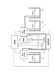
- FIG. 1 is a block diagram showing an example of the configuration of a manufacturing apparatus according to the first embodiment.
- FIG. 2 is a conceptual diagram showing an example of a mixed state of calcium hydroxide and a first liquid mixture containing phosphoric acid and silver nitrate by the manufacturing apparatus according to the first embodiment.
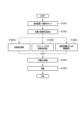
- FIG. 3 is a flowchart illustrating an example of a suspension production method executed by the production apparatus according to the first embodiment.
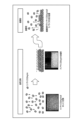
- FIG. 4 is a conceptual diagram showing an example of natural sedimentation in the suspension preparation method according to the first embodiment.
- FIG. 5 is a diagram showing an example of the relationship between the pH and color of a solution.
- FIG. 6 is a diagram showing an example of the results of applying gray AgHA, light gray AgHA, and white AgHA to a nonwoven fabric and investigating the antibacterial activity value using Escherichia coli. It is a figure which shows the example of the measurement result of the antibacterial activity value of.
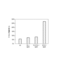
- Figure 7 shows a nonwoven fabric coated with a HA solution with a concentration of 0.5% by weight, a nonwoven fabric coated with a light gray AgHA solution with a concentration of 0.5%, and a nonwoven fabric coated with a white AgHA solution with a concentration of 0.5%. It is a graph showing an example of deodorizing effect with.
- FIG. 8 is a conceptual diagram showing an example of a mixed state of a second liquid mixture containing calcium hydroxide and silver nitrate and phosphoric acid by the manufacturing apparatus according to the second embodiment.
- FIG. 9 is a conceptual diagram showing an example of the configuration of a coating device for coating a nonwoven fabric with AgHA according to the third embodiment.
- FIG. 10 is a side view showing an example of a shower head and an ultrasonic vibrator.
- FIG. 11 is a perspective view showing an example of the upper surface of the support base.
- FIG. 12 is a flowchart illustrating an example of a method for applying AgHA to a nonwoven fabric, which is executed by the application apparatus according to the third embodiment.
- a production apparatus and method for producing antibacterial metal-containing HA having a large bacteria-inhibiting effect and deodorizing effect using a solution method will be described. More specifically, in the first embodiment, a production apparatus and method for producing light gray or white antibacterial metal-containing HA by controlling pH (hydrogen ion concentration index) will be described.
- the antibacterial metal may be a heavy metal.
- heavy metals having antibacterial properties include silver, copper, palladium, platinum, cadmium, nickel, cobalt, zinc, manganese, thallium, lead, and mercury.
- AgHA an apparatus and method for producing HA (hereinafter referred to as AgHA) containing silver (Ag) among metals having antibacterial properties will be described as an example. Note that it is also possible to produce HA containing other antibacterial metals, such as copper, by appropriately modifying the first embodiment.
- AgHA contained in the AgHA suspension produced according to the first embodiment can maintain a nanosize.
- FIG. 1 is a block diagram showing an example of the configuration of a manufacturing apparatus 1 according to the first embodiment.
- the manufacturing apparatus 1 injects (for example, drops) a first mixed solution containing phosphoric acid and silver nitrate into calcium hydroxide, and produces light gray by controlling the pH of the solution containing calcium hydroxide and the first mixed solution. Or make white AgHA.
- CuHA may be produced using copper nitrate or copper sulfate instead of silver nitrate.
- the production apparatus 1 may produce light gray or white AgHA by injecting a mixed solution of silver oxide, nitric acid, and phosphoric acid into calcium hydroxide.
- a mixed solution of silver oxide, nitric acid, and phosphoric acid it is difficult to produce light gray or white AgHA.
- a mixture of silver oxide, nitric acid, and phosphoric acid is used, light gray or white AgHA can be produced.
- the production apparatus 1 uses synthetic conditions that are lower than when using the first mixed solution containing phosphoric acid and silver nitrate. Set the pH used as a low value.
- the production device 1 includes a control device 2, a first container 3, a first injection device 4, a second injection device 5, a pH meter 6, a thermometer 7, a temperature adjustment device 8, a stirrer 37, and a first pouring device.
- a device 9 and a second pouring device 10 are provided.
- a light gray or white AgHA suspension 11 produced and concentrated by the production apparatus 1 is stored in a second container 12 .
- the various devices constituting the manufacturing apparatus 1 may be combined as appropriate.
- the pH meter 6 and the thermometer 7 may be one device.
- the first pouring device 9 and the second pouring device 10 may be one pump.
- the various devices constituting the manufacturing apparatus 1 may be separated as appropriate.
- the first container 3 is a container used for dropping a first liquid mixture containing phosphoric acid and silver nitrate onto calcium hydroxide, and the solution 13 which is a mixture of calcium hydroxide and the first liquid mixture. It may be divided into a container used for carrying out natural sedimentation.
- the control device 2 receives a signal indicating the pH measured by the pH meter 6 and a signal indicating the temperature measured by the thermometer 7.
- the control device 2 controls the amount of calcium hydroxide injected into the first container 3 by the first injection device 4 based on the pH indicated by the signal received from the pH meter 6 and the temperature indicated by the signal received from the thermometer 7.
- concentration, at least one of the concentration and injection rate (for example, dropping rate) of the first liquid mixture injected (for example, dropped) into the first container 3 by the second injection device 5, the pH of the solution 13 (synthesis pH), the temperature control of the solution 13 during AgHA synthesis and natural precipitation by the temperature control device 8 is controlled.
- the control device 2 may perform control to intentionally create calcium-deficient AgHA by additionally dropping the first mixed liquid after dropping the first mixed liquid and lowering the pH of the solution 13.
- control device 2 controls the concentration of calcium hydroxide so that the concentration of calcium hydroxide falls within the first range.
- the first range may be, for example, 0.01% or more and 50% or less.
- the control device 2 controls the concentration of the first liquid mixture so that the concentration of phosphoric acid is within the second range and the concentration of silver nitrate is within the third range.
- the second range may be, for example, 0.01% or more and 50% or less.
- the third range may be, for example, 0.01% or more and 50% or less.
- the control device 2 controls the injection rate of the first mixed liquid so that the injection rate of the first mixed liquid is within the fourth range with respect to the production amount of AgHA.
- the fourth range may be, for example, 0.01 ml/min/g or more and 100 ml/min/g or less.
- the fourth range may preferably be 0.1 ml/min/g or more and 10 ml/min/g or less.
- the control device 2 controls the injection amount of at least one of calcium hydroxide and the first liquid mixture so that the pH of the solution 13 in the first container 3 falls within the fifth range.
- the fifth range may be, for example, the pH at which light gray or white AgHA is produced.
- AgHA has a color such as brown, gray, light gray, or white, for example.
- the controller 2 controls the pH of the solution 13 in the first container 3 and controls the first mixing so that the solution 13 in the first container 3 is light gray or white. Control the amount of liquid injected.
- control device 2 may perform control so that the pH of the solution 13 in the first container 3 is 4 or more and 12 or less, thereby producing light gray AgHA.
- control device 2 may perform control so that the pH of the solution 13 in the first container 3 is 2 or more and 10 or less to produce white AgHA.
- the synthetic pH of AgHA used in the control device 2 is adjusted as appropriate depending on the purity, temperature, and Ag content of the raw materials.
- the control device 2 performs control so that the content of Ag with respect to HA is 0.01% by weight or more and 30% by weight or less, more preferably 0.1% by weight or more and 15% by weight or less.
- the content of Ag relative to HA is 0.4% by weight or more, the antibacterial properties of AgHA are greatly improved.
- the control device 2 controls the synthesis temperature at which the AgHA suspension is synthesized by mixing calcium hydroxide and the first mixed liquid, and the temperature during the reaction between the calcium hydroxide and the first mixed liquid at a sixth temperature.
- the temperature of the solution 13 is controlled to be within the range.
- the sixth range may be, for example, 5° C. or higher and 50° C. or lower.
- the sixth range may preferably be, for example, 5° C. or higher and 30° C. or lower.
- the temperature of the solution 13 tends to rise due to reaction heat, but the operation of the control device 2 and temperature adjustment device 8 can realize a state suitable for AgHA production.
- the control device 2 may include, for example, a storage device 2a and a processor 2b.
- the storage device 2a stores the software 2c.
- the storage device 2a may include a non-temporary storage device and a temporary storage device such as a cache memory.
- the software 2c may include a program and data.
- the processor 2b executes the software 2c stored in the storage device 2a, and executes various controls for producing the light gray or white AgHA suspension 11.
- the control device 2 executes control to cause the stirrer 37 to stir the solution 13 in the container 3 during mixing of calcium hydroxide and the first liquid mixture (AgHA synthesis). More specifically, the control device 2 transmits a signal indicating the rotational speed to the stirrer 37 when the second injection device 5 performs the dropping process of the first liquid mixture. For example, the control device 2 transmits to the stirrer 37 a signal for rotating the stirrer 37 at, for example, 50 rpm or more and 1000 rpm or less. More preferably, the control device 2 transmits to the stirrer 37 a signal for rotating the stirrer 37 at, for example, 100 rpm or more and 500 rpm or less.
- the controller 2 After pouring out the supernatant portion of the solution 13 from the first container 3 and before pouring out the concentrated AgHA suspension 11 from the first container 3, the controller 2 causes the stirrer 37 to The control for stirring the concentrated AgHA suspension 11 in the container 3 is executed. More specifically, the control device 2 transmits an instruction indicating the rotational speed to the stirrer 37 before pouring out the concentrated AgHA suspension 11. For example, the control device 2 transmits to the stirrer 37 a signal for rotating the stirrer 37 at, for example, 50 rpm or more and 1000 rpm or less. More preferably, the control device 2 transmits to the stirrer 37 a signal for rotating the stirrer 37 at, for example, 100 rpm or more and 500 rpm or less. By stirring with the stirrer 37, the concentration of the concentrated light gray or white AgHA suspension 11 can be made uniform.
- the control device 2 instructs the first pouring device 9 to pour out the supernatant portion of the solution 13 contained in the first container 3.
- the control device 2 instructs the second pouring device 10 to pour out the sedimented portion (i.e., the concentrated AgHA suspension 11) of the solution 13 contained in the first container 3. do.
- the first container 3 contains calcium hydroxide (liquid) injected from the first injection device 4.
- the first container 3 receives the first liquid mixture injected (for example, dropped) by the second injection device 4.
- the first injection device 4 receives a signal indicating the concentration of calcium hydroxide from the control device 2.
- the first injection device 4 adjusts the concentration of calcium hydroxide based on the received signal, and injects the adjusted concentration calcium hydroxide into the first container 3.
- the purity of calcium hydroxide may be 90% or more and 100% or less.
- the second injection device 5 receives from the control device 2 a signal indicating the concentration of phosphoric acid, a signal indicating the concentration of silver nitrate, and a signal indicating the injection speed of the first mixed liquid.
- the second injection device 5 mixes phosphoric acid at a concentration indicated by the received signal and silver nitrate at a concentration indicated by the signal to be received to generate a first mixed solution, and It is dripped into the solution 13 containing calcium hydroxide stored in the first container 3 at the injection rate indicated by the signal.
- the pH meter 6 measures the pH of the solution 13 stored in the first container 3 and sends a signal indicating the pH to the control device 2.
- the thermometer 7 measures the temperature of the solution 13 stored in the first container 3 and sends a signal indicating the temperature to the control device 2.
- the temperature adjustment device 8 receives a signal indicating the temperature from the control device 2.
- the temperature control device 8 controls the signal received by the solution 13 in the first container 3 during mixing of calcium hydroxide and the first liquid mixture (during AgHA synthesis) and while performing natural sedimentation on the solution 13.
- the temperature of the solution 13 in the first container 3 is controlled (eg, heated or cooled) so that the temperature indicated by is reached.
- the stirrer 37 receives a signal indicating the rotation speed from the control device 2.
- the stirrer 37 stirs the solution 13 in the container 3 according to the rotational speed indicated by the received signal.
- the stirrer 37 stirs the solution 13 when dropping the first liquid mixture (during AgHA synthesis). Further, the stirrer 37 stirs the concentrated AgHA suspension 11 before pouring out the concentrated AgHA suspension 11. There is a concentration gradient in the settling part after the supernatant part is poured out.
- the concentration of the sedimented portion can be made uniform by stirring the sedimented portion.
- the first dispensing device 9 receives a signal indicating a dispensing instruction from the control device 2.
- the first pouring device 9 pours out the supernatant portion of the solution 13 from the first container 3 based on the received signal, and pours out the sedimented portion of the solution 13 (i.e., the concentrated light gray or white AgHA suspension). 11) is left in the first container 3.
- the water intake port of the first pouring device 9 is movable up and down depending on the boundary position between the supernatant portion and the sedimentation portion. More specifically, the height of the water intake port of the first pouring device 9 is adjusted so that it is above the boundary position between the supernatant portion and the settling portion. Thereby, the supernatant portion can be efficiently poured out and the sedimented portion can be left in the first container 3.
- the second dispensing device 10 receives a signal indicating a dispensing instruction from the control device 2. Based on the received signal, the second pouring device 10 converts the sedimented portion of the solution 13 in the first container 3 into a concentrated light gray or white AgHA suspension 11 into a second container 12 for transportation. Inject into.
- FIG. 2 is a conceptual diagram showing an example of the mixing state of calcium hydroxide and the first mixed liquid (AgHA synthesis state) by the production apparatus 1 according to the first embodiment.
- the first pouring device 9 and the second pouring device 10 of the manufacturing apparatus 1 are omitted.
- the third container 4a contains a calcium hydroxide solution.
- the first injection device 4 adjusts the concentration of calcium hydroxide to the concentration indicated by the signal received from the control device 2, and injects the calcium hydroxide with the adjusted concentration into the first container 3.
- the fourth container 5a contains a solution of phosphoric acid.
- the fifth container 5b contains a silver nitrate solution.
- the second injection device 5 adjusts the concentration of phosphoric acid to the concentration indicated by the signal received from the control device 2. Further, the second injection device 5 adjusts the concentration of silver nitrate to the concentration indicated by the signal received from the control device 2. Further, the second injection device 5 mixes phosphoric acid and nitric acid to generate a first mixed liquid. Then, the second injection device 5 drips the first liquid mixture whose concentration has been adjusted into the first container 3 at a dropping speed indicated by the signal received from the control device 2 .
- the control device 2 receives a signal indicating the pH of the solution 13 from the pH meter 6, and controls the operation of the first injection device 4 and the second injection device 5 and the stirring of the stirrer 37 based on the pH of the solution 13. Control processing.
- the control device 2 receives a signal indicating the temperature of the solution 13 from the thermometer 7, and controls the operation of the temperature adjustment device 8 based on the temperature of the solution 13.
- the first injection device 4 and the second injection device 5 may be, for example, tube pumps.
- a fourth container 5a containing phosphoric acid and a fifth container 5b containing silver nitrate are used separately.
- the fourth container 5a and the fifth container 5b may be combined into one container.
- this one container contains a first liquid mixture obtained by mixing phosphoric acid and silver nitrate in advance.
- the second injection device 5 sucks the first liquid mixture in this one container and drips it into the solution 13 in the first container 3.
- FIG. 3 is a flowchart illustrating an example of a method for producing a light gray or white AgHA suspension 11 performed by the production apparatus 1 according to the first embodiment. The manufacturing method shown in FIG. 3 is executed under the control of the control device 2.
- the first injection device 4 injects calcium hydroxide at a concentration specified by the control device 2 into the first container 3.
- the stirrer 37 operates at the rotation speed specified by the control device 2 to stir the solution 13 in the first container 3.
- the second injection device 5 drops the first liquid mixture into the solution 13 (calcium hydroxide) in the first container 3 at the concentration and injection rate specified by the control device 2.
- the pH meter 6 measures the pH of the solution 13 in the first container 3 and sends a signal indicating the pH to the control device 2, and the thermometer 7 measures the temperature of the solution 13 in the first container 3. A signal indicating the measured temperature is transmitted to the control device 2.
- control device 2 determines that the relationship between the concentration of calcium hydroxide, the concentration and injection rate of the first mixed liquid, the pH of the solution 13 in the first container 3, and the temperature of the solution 13 is that AgHA is light gray or white. Determine whether or not the synthesis condition is satisfied.
- control device 2 determines that the synthesis conditions are not satisfied, in S306, the control device 2 controls the new concentration of calcium hydroxide, the new concentration of the first mixed liquid, the new injection rate of phosphoric acid, and the new concentration of the first mixed liquid. Determine the pH, the new temperature of the solution 13 in the first container 3. The control device 2 then transmits a signal indicating the new concentration of calcium hydroxide to the first injection device 4. The first injection device 4 adjusts the concentration of calcium hydroxide based on the signal received from the control device 2. The control device 2 transmits a signal indicating the concentration of the new first mixed liquid and a signal indicating the injection speed of the new first mixed liquid to the second injection device 5.
- the second injection device 5 adjusts the concentration and injection rate of the first mixed liquid based on the signal received from the control device 2.
- the control device 2 sends a signal indicating the new temperature to the temperature adjustment device 8.
- Temperature adjustment device 8 adjusts the temperature of solution 13 based on the signal received from control device 2 . After that, the process returns to S301.
- control device 2 does not need to determine the new concentration of calcium hydroxide, and sends a signal indicating the new concentration of calcium hydroxide to the first injection device 4. There is no need to send it to . In this case, the process returns to S302.
- control device 2 determines in S305 that the synthesis conditions are satisfied, in S307 the control device 2 determines whether the termination conditions for the operation of dropping the first mixed liquid onto calcium hydroxide (dropping termination conditions) are satisfied. to judge.
- the dropping end condition may be, for example, that the pH of the solution 13 in the first container 3 has reached the target range (target pH).
- the target pH is, for example, a pH at which the ratio of AgHA produced is equal to or higher than a threshold value and the AgHA produced becomes light gray or white.
- the control device 2 causes the second injection device 5 to drip the first mixed liquid again as appropriate, so that the pH of the solution 13 increases.
- the condition is stable, it may be determined that the drop termination condition is satisfied.
- the dropping termination conditions are, for example, that the ratio of AgHA to be produced is equal to or higher than a threshold value, the pH is such that the AgHA to be produced is light gray or white, and the amount of solution 13 in the first container 3 is below the threshold value. It may also be said to exceed.
- the control device 2 may intentionally produce calcium-deficient AgHA by additionally dropping the first mixed liquid after dropping the first mixed liquid and lowering the pH of the solution 13.
- control device 2 determines that the termination conditions are not satisfied, the process returns to S301. Note that in S306 of the first embodiment, if the control device 2 does not determine a new concentration of calcium hydroxide, the process may return to S302.
- control device 2 determines that the end condition is satisfied, in S308, the control device 2 transmits a stop signal to the first injection device 4, the second injection device 5, and the stirrer 37.
- the first injection device 4 and the second injection device 5 stop their injection operations in accordance with the signal received from the control device 2.
- the stirrer 37 stops its stirring operation in accordance with the signal received from the control device 2.
- control device 2 transmits a signal indicating a temperature suitable for natural sedimentation to the temperature adjustment device 8.
- Temperature adjustment device 8 adjusts the temperature of solution 13 based on the signal received from control device 2 .
- step S310 natural sedimentation of the solution 13 in the first container 3 is performed for a predetermined period of time or more.
- the first pouring device 9 pours out the supernatant portion of the solution 13 in the first container 3 under the control of the control device 2, and leaves the sedimented portion in the first container 3.
- the stirring device 37 stirs the concentrated light gray or white AgHA suspension 11, which is the sedimented portion in the first container 3, under the control of the control device 2.
- the second pouring device 10 pours out the concentrated light gray or white AgHA suspension 11 in the first container 3 under the control of the control device 2, and stores it in the second container 12. do.
- FIG. 4 is a conceptual diagram showing an example of natural sedimentation in the method for producing the AgHA suspension 11 according to the first embodiment.
- the AgHA-containing solution 13 prepared in the first container 3 is subjected to natural sedimentation for a predetermined period of time.
- the predetermined time for natural sedimentation may be, for example, 1 day or more and 60 days or less, more preferably 9 days or more and 28 days or less.
- Nanosized AgHA in the solution 13 slowly settles. Removal of the supernatant portion of solution 13 leaves a concentrated AgHA suspension 11, which is the sedimented portion of solution 13. AgHA contained in this AgHA suspension 11 maintains a nanosize.
- a dentifrice in which nano-sized AgHA is diffused can be produced.
- the target pH is a pH at which the concentrated AgHA suspension 11 becomes light gray or white.
- the AgHA suspension 11 is prepared using a first mixed solution of phosphoric acid and silver nitrate.
- a manufacturing method that uses silver oxide instead of silver nitrate as the Ag source, but since silver oxide does not dissolve in phosphoric acid, silver nitrate is used as the Ag source in the first embodiment.
- Cu may also be used as the antibacterial heavy metal.
- Cu(NO 3 ), Cu(NO 4 ), or Cu(NO 3 ) 2 is used instead of silver nitrate to prepare a CuHA suspension containing CuHA.
- FIG. 5 is a diagram showing an example of the relationship between the pH and color of the solution 13.
- control device 2 controls the pH of the solution 13 so that the color of AgHA is light gray or white and the ratio of AgHA in the solution 13 exceeds a predetermined value. .
- a crystal of calcium-deficient AgHA has a structure in which the amount of Ag uptake is greater than that of an AgHA crystal. Therefore, the higher the ratio of calcium-deficient AgHA, the higher the antibacterial effect of the produced AgHA suspension 11.
- White AgHA contains more calcium-deficient AgHA and has a higher Ag uptake than gray AgHA.
- FIG. 6 is a diagram showing an example of the results of applying gray AgHA, light gray AgHA, and white AgHA to a nonwoven fabric and investigating the antibacterial activity value using Escherichia coli.
- FIG. 6 shows the results of investigating antibacterial activity values for a nonwoven fabric coated with a 0.1% AgHA solution and a nonwoven fabric coated with a 0.5% AgHA solution.
- AgHA contained in the AgHA solution the Ag content with respect to HA is 2% by weight.
- An antibacterial activity value of 2 or more and less than 3 indicates an antibacterial effect, and a value of 3 or more indicates a large antibacterial effect.
- Figure 7 shows a nonwoven fabric coated with a HA solution with a concentration of 0.5% by weight, a nonwoven fabric coated with a light gray AgHA solution with a concentration of 0.5%, and a nonwoven fabric coated with a white AgHA solution with a concentration of 0.5%. It is a graph showing an example of deodorizing effect with. In FIG. 7, the vertical axis indicates the reduction rate of ammonia odor. In the AgHA shown in FIG. 7, the Ag content with respect to HA is 2% by weight.
- Light gray AgHA has a higher deodorizing effect than HA and gray AgHA.
- the deodorizing effect of white AgHA is approximately 4 to 5 times higher than that of light gray AgHA.
- the light gray or white AgHA produced in the first embodiment has strong bactericidal and deodorizing effects.
- a solution 13 is prepared and concentrated, and the concentrated AgHA suspension 11 is stored in a second container 12. 2 containers 12 are transported.
- the solution 13 containing AgHA having a small particle size can be adjusted.
- the number of bacteria can be controlled by preparing and efficiently concentrating the solution 13 and adjusting the pH of the solution 13.
- AgHA is shipped and used as a suspension. Therefore, aggregation of AgHA particles can be suppressed, and AgHA with small particle size can be used.
- concentration is performed by natural sedimentation.
- concentration using a centrifuge causes AgHA particles to aggregate, making redispersion difficult.
- concentration since concentration is performed by natural sedimentation, aggregation of AgHA particles can be suppressed. By concentrating it, the transport of the AgHA suspension 11 can be made more efficient and easier to handle.
- the period required for natural sedimentation varies depending on the temperature of the solution 13 in the first container 3. For example, in experiments, the number of days required to concentrate to about 3% was 9 to 28 days. It was obtained from data obtained by preparing 200 100 L AgHA suspensions 11 that natural sedimentation is affected by the temperature atmosphere. Based on this result, in the first embodiment, the control device 2 controls the temperature of the solution 13 in the first container 3 to a temperature suitable for natural sedimentation. In the production apparatus 1 according to the first embodiment, the sedimentation period can be shortened by performing the natural sedimentation at a temperature of 5° C. or higher and 40° C. or lower, and the solution 13 can be efficiently concentrated to form the AgHA suspension 11. can be created.
- the concentrated suspension 11 is stirred by the stirrer 37 and then stored in the second container 12. Therefore, in the first embodiment, the concentration of the concentrated suspension 11 can be made uniform.
- the effect of suppressing the number of bacteria can be obtained by controlling the storage temperature of the solution 13 and the concentrated AgHA suspension 11 to a range of 2° C. or higher and 30° C. or lower. More preferably, the number of bacteria can be suppressed by controlling the storage temperature of the solution 13 and the concentrated AgHA suspension 11 to a range of 2° C. or higher and 20° C. or lower.
- control device 2 and the temperature adjustment device 8 control the temperature of the solution 13 and the temperature of the concentrated AgHA suspension 11 in a range of 2°C or more and 30°C or less, more preferably 2°C or more and 20°C or less. It may be controlled within a range.
- the control device 2 and the temperature adjustment device 8 control the temperature of the solution 13 during the sedimentation period to a range of 15° C. or more and 25° C. or less in order to shorten the sedimentation period, and after the sedimentation period has elapsed.
- the temperature of the solution 13 and the concentrated HA suspension 11 may be controlled within the range of 2° C. or higher and 20° C. or lower.
- the temperature control device 8 controls the temperature of the concentrated AgHA suspension 11 in the second container 12 in addition to controlling the temperature of the solution 13 in the first container 3. Good too.
- the control device 2 may use the temperature adjustment device 8 to control the temperature of the concentrated AgHA suspension 11 in the second container 12 to a range of 2° C. or more and 20° C. or less.
- the solution 13 is concentrated by natural sedimentation.
- the concentration may also be carried out by centrifugation using very low centrifugal force to maintain the dispersion of AgHA in solution 13.
- the AgHA suspension concentrated by natural sedimentation may be further concentrated using a centrifuge using a weak centrifugal force.
- the stirrer 37 may vigorously stir the AgHA suspension in order to disperse the AgHA within the concentrated AgHA suspension.
- the prepared solution 13 (AgHA suspension) is concentrated is explained as an example.
- the solution 13 may be stirred with the stirrer 37 and transferred to the second container 11.
- the solution 13 may be diluted with water, stirred with a stirrer 37, and transferred to the second container 11.
- the second injection device 5 In the first embodiment, the second injection device 5 generates a first mixed solution of phosphoric acid and silver nitrate, and drops the first mixed solution into the solution 13 in the container 3 .
- the first injection device 4 mixes the calcium hydroxide in the container 4a and the silver nitrate in the container 5b, and A liquid is generated, the second mixed liquid is injected into the container 3, and then the second injection device 5 drops the calcium hydroxide in the container 5a to the solution 13 in the container 3.
- an AgHA suspension 11 containing AgHA having a large antibacterial effect and deodorizing effect and a small particle size can be produced. I can do it.
- AgHA is applied to a nonwoven fabric by dipping the nonwoven fabric in an AgHA suspension.
- application is assumed to be a technique that utilizes wetting and solidification.
- FIG. 9 is a conceptual diagram showing an example of the configuration of a coating device 15 for coating a nonwoven fabric 14 with AgHA according to the third embodiment.
- FIG. 9 illustrates a side sectional view of the coating device 15.
- the coating device 15 mainly includes a delivery section 16 that sends out the nonwoven fabric 14 before treatment, a water tank section 17, a drying section 18, a winding section 19 that winds up the nonwoven fabric 14 after treatment, and a droplet receiving section 20.
- the continuous nonwoven fabric 14 is fed out from the feeding section 16, its position is adjusted by the rollers 211 to 214 of the water tank section 17 and the roller 22 of the drying section 18, and the continuous nonwoven fabric 14 is moved from left to right in FIG. 9 by winding up by the winding section 19. do.
- the direction from right to left in FIG. 9 is referred to as the nonwoven fabric feeding direction.
- the water tank section 17 includes rollers 211 to 214, a water tank 23, a first pump 24, a second pump 25, a shower head 26, an ultrasonic vibrator 27, and a cooler 28.
- the rollers 211 and 212 guide the nonwoven fabric 14 fed out from the feeding section 16 into the AgHA suspension 29 (corresponding to the AgHA suspension 11) stored in the water tank 23.
- the roller 212 further guides the nonwoven fabric 14 between the shower head 26 and the ultrasonic vibrator 27.
- the rollers 213 and 214 guide the nonwoven fabric 14 that has passed between the shower head 26 and the ultrasonic vibrator 27 out of the suspension 29 stored in the water tank 23.
- the roller 214 further returns the excess suspension contained in the nonwoven fabric 14 from the nonwoven fabric 14 to the water tank 23.
- the water tank 23 stores the suspension 29.
- the water tank 29 includes a first outlet 30 , an inlet 31 , and a second outlet 32 .
- the first outlet 30 is provided on the first side surface 23a of the water tank 23.
- the inlet 31 is provided on the second side surface 23b of the water tank 23.
- the second side surface 23b may be a surface facing the first side surface 23a.
- the first pump 24 discharges the suspension 29 from the first outlet 30 to the outside of the water tank 23 and causes the suspension 29 to flow into the water tank 23 from the inlet 31. As a result, the suspension 29 flows within the water tank 23.
- the second outlet 32 is provided on the bottom surface 23c of the water tank 23.
- the second pump 25 discharges the suspension 29 from the second outlet 32 to the outside of the water tank 23 and supplies the suspension 29 to the shower head 26.
- the suspension 29 that exists deep in the water tank 23 and has a high concentration of AgHA is supplied to the shower head 26 , the suspension 29 is spouted from the shower head 26 , and the suspension 29 is flowed in the water tank 23 . can be done.
- the shower head 26 spouts a suspension 29 from its liquid jetting surface.
- the liquid ejection surface of the shower head 26 faces the vibration surface of the ultrasonic vibrator 27 with a gap therebetween.
- the ultrasonic transducer 27 is an example of an ultrasonic generator.
- the ultrasonic vibrator 27 vibrates at a high frequency and emits ultrasonic waves from its ultrasonic emission surface.
- the ultrasonic transducer 27 may be, for example, a device that emits powerful ultrasonic waves for cell disruption.
- the ultrasonic wave emitting surface of the ultrasonic vibrator 27 faces the liquid discharge surface of the shower head 26 via a gap.
- the shower head 26 is placed at the top and the ultrasonic vibrator 27 is placed at the bottom.
- the gap between the liquid discharge surface of the shower head 26 and the vibration surface of the ultrasonic vibrator 27 is, for example, larger than the thickness of the nonwoven fabric 14 and 3 mm or less. From the results of the experiment, it was possible to infiltrate the suspension 29 into the nonwoven fabric 14 even when the gap was, for example, 6.5 mm or less. By making the ultrasonic waves more powerful and/or making the water flow of the suspension 29 more powerful, the gap can be applied in a range of 50 mm or less.
- the nonwoven fabric 14 that has passed through the gap between the shower head 26 and the ultrasonic vibrator 27 is soaked with the suspension 29.
- the cooler 28 suppresses the temperature rise of the suspension 29 in the water tank 23 due to ultrasonic waves. More specifically, the cooler 28 operates when the temperature of the suspension 29 in the water tank 23 exceeds a threshold value and lowers the temperature of the suspension 29.
- the droplet receiving section 20 is arranged between the water tank section 17 and the drying section 18.
- the droplet receiver 20 receives droplets of the suspension 29 dripping from the nonwoven fabric 14 .
- the drying section 18 includes a housing 33, a plurality of rollers 22, an air outlet 34, and a support stand 35.
- the surface of the casing 33 on the side into which the nonwoven fabric 14 is carried may be, for example, a transparent acrylic plate 33a.
- the acrylic plate 33a has an opening 33c for carrying the nonwoven fabric 14 into the housing 33 from the outside.
- the surface of the casing 33 on the side from which the nonwoven fabric 14 is carried out may be, for example, a flexible silicon plate 33b.
- a flexible silicon plate 33b For example, only the upper portion of the silicon plate 33b is connected to the upper surface of the casing 33, and the silicon plate 33b is arranged like a banner.
- the operator can set and change the inside of the housing 33 by raising this silicon plate 33b.
- the flexible silicon plate 33b in this manner, the operator can easily observe and change the internal state of the drying section 18.
- gas such as air inside the housing 33 can be flexibly discharged.
- the silicon plate 33b has an opening 33d for transporting the nonwoven fabric 14 from the inside of the casing 33 to the outside.
- the plurality of rollers 22 are arranged so that the nonwoven fabric 14 carried in through an opening 33c formed in an acrylic plate 33a of the drying section 18 is carried out through an opening 33d formed in a silicone plate 33b of the drying section 18. , move.
- the air outlet 34 discharges air (for example, warm air) for drying the nonwoven fabric 14.
- the air outlet 34 discharges air in a direction perpendicular to the plane of the nonwoven fabric 14 on the side of the acrylic plate 33a inside the housing 33. More specifically, the air outlet 34 is installed on the upper surface of the casing 33 on the import side of the nonwoven fabric 14 inside the casing 33, and discharges downward air to the nonwoven fabric 14.
- the shape of the air outlet 34 is preferably circular, for example, but other shapes such as an ellipse or a rectangle may also be used.
- a support stand 35 is installed on the roller 22 side of the nonwoven fabric 14 opposite to the blowout port 34 side to prevent the nonwoven fabric 14 exposed to the wind from getting caught up in the roller 22.
- the support stand 35 is inside the casing 33 and supports the nonwoven fabric 14 on the carry-in side where the nonwoven fabric 14 receives wind.
- the upper surface of the support stand 35 (the surface that supports the nonwoven fabric 14) is net-shaped.
- FIG. 10 is a side view showing an example of the shower head 26 and the ultrasonic vibrator 27.
- the shower head 26 and the ultrasonic vibrator 27 are provided to face each other with a gap 36, for example, larger than the thickness of the nonwoven fabric 14 and 3 mm or less.
- a shower head 26 is provided on the top and an ultrasonic transducer 27 is provided on the bottom.
- other arrangement relationships may be applied, such as the shower head 26 being at the bottom and the ultrasonic transducer 27 being at the top.
- a plurality of holes are formed in the lower surface of the shower head 26.
- Suspension liquid 29 is ejected from holes in the lower surface of shower head 26 toward nonwoven fabric 14 .
- the ultrasonic vibrator 27 vibrates the nonwoven fabric 14 and the suspension 29 present in the gap 36 with ultrasonic waves.
- the nonwoven fabric 14 immersed in the suspension 29 in the water tank 23 contains air bubbles.
- suspension 29 ejected from shower head 26 is pressed against nonwoven fabric 14 . Due to the synergistic effect of the ejection of the suspension 29 and the ultrasonic waves generated from the ultrasonic vibrator 27, air bubbles are discharged from the nonwoven fabric 14, and the hydrophobic nonwoven fabric 14 is wetted by the suspension 29.
- FIG. 11 is a perspective view showing an example of the upper surface of the support stand 35.
- the efficiency with which the air discharged from the blowing port 34 blows through the nonwoven fabric 14 can be improved, and furthermore, the nonwoven fabric 14 can be prevented from being caught up in the rotor 22 under the support stand 35. can be prevented.
- FIG. 12 is a flowchart illustrating an example of a method for applying AgHA to the nonwoven fabric 14, which is executed by the application device 15 according to the third embodiment.
- step S1201 the nonwoven fabric 14 is set in the coating device 15 in a state that it can be moved from the feeding section 16 to the winding section 19 via the water tank section 17 and the drying section 18 in the nonwoven fabric feeding direction.
- step S1202 the water tank 23 stores the suspension 29.
- step S1203a the first pump 24 circulates the suspension 29 in the water tank 23.
- step S1203b the second pump 25 supplies the suspension 29 in the water tank 23 to the shower head 26, and causes the shower head 26 to spout the suspension 29.
- step S1203c the ultrasonic vibrator 27 emits ultrasonic waves to the nonwoven fabric 14 by vibration operation to remove air bubbles from the nonwoven fabric 14.
- step S1204 the feeding unit 16, rollers 211 to 214, roller 22, and winding unit 19 move the nonwoven fabric 14 in the nonwoven fabric feeding direction.
- step S1205 the drying unit 18 dries the nonwoven fabric 14 soaked with the suspension 29 by using the air discharged from the air outlet 34.
- the particle size of AgHA in suspension 29 is smaller than that of dried AgHA.
- AgHA having a small particle size is applied to the nonwoven fabric 14 by impregnating the suspension 29 into the nonwoven fabric 14 to make it wet, and then drying it.
- the nonwoven fabric 14 is hydrophobic, simply soaking the nonwoven fabric 14 in the suspension 29 may not sufficiently soak the suspension 29 into the nonwoven fabric 14, and it may not be possible to sufficiently apply AgHA to the nonwoven fabric 14.
- the nonwoven fabric 14 is vibrated by the ultrasonic vibrator 27, and the suspension 29 is ejected from the shower head 26 toward the nonwoven fabric 14 to generate a water flow. Air bubbles are expelled to make the nonwoven fabric 14 wet with the suspension 29, and then the nonwoven fabric 14 is quickly dried.
- the shower head 26, in addition to ejecting the homogeneous suspension 29, is also responsible for expelling air bubbles.
- AgHA which is a suspended component and has a small particle size, can be attached to the nonwoven fabric 14.
- the concentration of the suspension 29 in the water tank 23 can be made uniform by vibrating the suspension 29 using the ultrasonic vibrator 27.
- the nonwoven fabric 14 passes through the gap 36 between the shower head 26 and the ultrasonic vibrator 27 that face each other.
- the width of this gap 36 larger than the thickness of the nonwoven fabric 14 and 3 mm or less, permeation of the suspension 29 into the nonwoven fabric 14 can be promoted.
- the concentration of the suspension 29 may be set to 0.005% or more and 5.0% or less.
- AgHA can be sufficiently adhered to the nonwoven fabric 14, and it is possible to prevent AgHA from excessively adhering to the fibers of the nonwoven fabric 14 and causing the AgHA powder to fall off.
- the appropriate concentration of suspension 29 will vary depending on particle size.
- the suspension 29 may be replenished into the water tank 23 so that the concentration of the suspension 29 in the water tank 23 is equal to or higher than a predetermined value.
- the inside of the nonwoven fabric 14 can be efficiently
- the nonwoven fabric 14 can be wetted by the suspension 29 by expelling the air bubbles.
- a shower head 26 and an ultrasonic vibrator 27 are used to wet the hydrophobic nonwoven fabric 14.
- the nonwoven fabric is hydrophilic, the nonwoven fabric can be wetted without using the ultrasonic transducer 27.
- the nonwoven fabric 14 passes between the shower head 26 and the ultrasonic vibrator 27 , the extra suspension attached to the nonwoven fabric 14 is squeezed out by the roller 214 , and the nonwoven fabric 14 returns to the water tank 23 .
- the moderately wet nonwoven fabric 14 is then conveyed into the drying section 18.
- the suspension 29 discharged from the first outlet 30 is caused to flow in from the inlet 31, thereby further reducing the suspension in the water tank 23.
- the liquid 29 can be stirred and circulated. Thereby, the concentration of the suspension 29 in the water tank 23 can be made uniform, and AgHA can be uniformly applied to the nonwoven fabric 14.
Landscapes
- Health & Medical Sciences (AREA)
- Life Sciences & Earth Sciences (AREA)
- Chemical & Material Sciences (AREA)
- Inorganic Chemistry (AREA)
- General Health & Medical Sciences (AREA)
- Veterinary Medicine (AREA)
- Public Health (AREA)
- Animal Behavior & Ethology (AREA)
- Epidemiology (AREA)
- Organic Chemistry (AREA)
- Engineering & Computer Science (AREA)
- Environmental Sciences (AREA)
- Birds (AREA)
- Oral & Maxillofacial Surgery (AREA)
- Wood Science & Technology (AREA)
- Dentistry (AREA)
- Plant Pathology (AREA)
- Pest Control & Pesticides (AREA)
- Zoology (AREA)
- Hematology (AREA)
- Materials Engineering (AREA)
- Heart & Thoracic Surgery (AREA)
- Surgery (AREA)
- Vascular Medicine (AREA)
- Agronomy & Crop Science (AREA)
- Pharmaceuticals Containing Other Organic And Inorganic Compounds (AREA)
- Agricultural Chemicals And Associated Chemicals (AREA)
Abstract
In the present embodiment, the production apparatus is provided with a first injection device, a second injection device, a control device, and a pouring device. The first injection device injects calcium hydroxide into a container. The second injection device injects a mixed solution prepared by mixing silver nitrate, copper nitrate or copper sulfate with phosphoric acid into the solution stored in the container. The control unit controls at least one of the concentration and the injection speed of the mixed solution to be injected by the second injection device in such a manner that the pH value measured by a pH meter falls within a predetermined range, thereby producing a light-gray or white hydroxyapatite suspension containing an antibacterial metal in the container.
Description
本発明は、抗菌性金属含有ハイドロキシアパタイトの作製装置及び方法に関する。
The present invention relates to an apparatus and method for producing antibacterial metal-containing hydroxyapatite.
ハイドロキシアパタイト(以下、HAと表記する)は、例えば、Ca10(PO4)6(OH)2で表される。HAの作製方法の一例として溶液法がある。一般に、HAは乾燥した粉末状で運搬、販売、及び、利用される。HAは乾燥した場合に凝集する。凝集したHAの粒子サイズはマイクロサイズとなる。
Hydroxyapatite (hereinafter referred to as HA) is represented by, for example, Ca 10 (PO 4 ) 6 (OH) 2 . An example of a method for producing HA is a solution method. Generally, HA is transported, sold, and used in dry powder form. HA aggregates when dried. The particle size of aggregated HA becomes micro-sized.
本発明の実施形態は、菌抑制効果の大きい抗菌性金属含有HAの作製装置及び方法を提供する。
Embodiments of the present invention provide an apparatus and method for producing antibacterial metal-containing HA that has a large bacterium-inhibiting effect.
ある実施形態に係る作製装置は、第1の注入装置と、第2の注入装置と、制御装置とを含む。第1の注入装置は、容器に水酸化カルシウムを注入する。第2の注入装置は、容器に収容されている溶液に、硝酸銀、硝酸銅、又は、硫酸銅とリン酸とを混合した混合液を注入する。制御装置は、pH計によって計測された容器内の溶液のpHが所定の範囲になるように、第2の注入装置によって注入される混合液の濃度と注入速度とのうちの少なくとも一方を制御し、容器内にライトグレー又はホワイトの抗菌性金属含有ハイドロキシアパタイト懸濁液を作製する。
A manufacturing apparatus according to an embodiment includes a first injection device, a second injection device, and a control device. A first injection device injects calcium hydroxide into the container. The second injection device injects silver nitrate, copper nitrate, or a mixed solution of copper sulfate and phosphoric acid into the solution contained in the container. The control device controls at least one of the concentration and injection rate of the liquid mixture injected by the second injection device so that the pH of the solution in the container as measured by the pH meter falls within a predetermined range. , prepare a light gray or white antibacterial metal-containing hydroxyapatite suspension in a container.
別の実施形態に係る作製装置は、第1の注入装置と、第2の注入装置と、制御装置とを含む。第1の注入装置は、容器に、硝酸銀、硝酸銅、又は、硫酸銅と水酸化カルシウムとを混合した混合液を注入する。第2の注入装置は、容器に収容されている溶液に、リン酸を注入する。制御装置は、pH計によって計測された容器内の溶液のpHが所定の範囲になるように、第2の注入装置によって注入されるリン酸の濃度と注入速度とのうちの少なくとも一方を制御し、容器内にライトグレー又はホワイトの抗菌性金属含有ハイドロキシアパタイト懸濁液を作製する。
A manufacturing device according to another embodiment includes a first injection device, a second injection device, and a control device. The first injection device injects silver nitrate, copper nitrate, or a mixed solution of copper sulfate and calcium hydroxide into the container. The second injection device injects phosphoric acid into the solution contained in the container. The control device controls at least one of the concentration and injection rate of the phosphoric acid injected by the second injection device so that the pH of the solution in the container as measured by the pH meter falls within a predetermined range. , prepare a light gray or white antibacterial metal-containing hydroxyapatite suspension in a container.
本発明の実施形態によれば、菌抑制効果の大きい抗菌性金属含有HAを作製することができる。
According to the embodiments of the present invention, it is possible to produce antibacterial metal-containing HA that has a large bacterium-inhibiting effect.
以下、本発明の実施形態を、図面を参照して説明する。なお、以下の説明において、略又は実質的に同一の機能及び構成要素については、同一符号を付し、説明を省略するか、又は、必要な場合にのみ説明を行う。
Hereinafter, embodiments of the present invention will be described with reference to the drawings. In the following description, substantially or substantially the same functions and components will be denoted by the same reference numerals, and the description will be omitted or will be explained only when necessary.
(第1の実施形態)
第1の実施形態においては、溶液法を用いて菌抑制効果及び消臭効果の大きい抗菌性金属含有HAを作製する作製装置及び方法を説明する。より具体的には、第1の実施形態においては、pH(水素イオン濃度指数)を制御することによりライトグレー又はホワイトの抗菌性金属含有HAを作製する作製装置及び方法を説明する。 (First embodiment)
In the first embodiment, a production apparatus and method for producing antibacterial metal-containing HA having a large bacteria-inhibiting effect and deodorizing effect using a solution method will be described. More specifically, in the first embodiment, a production apparatus and method for producing light gray or white antibacterial metal-containing HA by controlling pH (hydrogen ion concentration index) will be described.
第1の実施形態において、抗菌性を有する金属は重金属でもよい。抗菌性を有する重金属としては、例えば、銀、銅、パラジウム、白金、カドミウム、ニッケル、コバルト、亜鉛、マンガン、タリウム、鉛、水銀などがある。第1の実施形態においては、抗菌性を有する金属のうち銀(Ag)を含有するHA(以下、AgHAと表記する)の作製装置及び方法を例として説明する。なお、例えば銅などのような他の抗菌性金属を含有するHAの作製も、第1の実施形態を適宜変更して実現可能である。
In the first embodiment, the antibacterial metal may be a heavy metal. Examples of heavy metals having antibacterial properties include silver, copper, palladium, platinum, cadmium, nickel, cobalt, zinc, manganese, thallium, lead, and mercury. In the first embodiment, an apparatus and method for producing HA (hereinafter referred to as AgHA) containing silver (Ag) among metals having antibacterial properties will be described as an example. Note that it is also possible to produce HA containing other antibacterial metals, such as copper, by appropriately modifying the first embodiment.
第1の実施形態によって作製されたAgHA懸濁液に含まれているAgHAは、ナノサイズを維持することができる。
AgHA contained in the AgHA suspension produced according to the first embodiment can maintain a nanosize.
図1は、第1の実施形態に係る作製装置1の構成の例を示すブロック図である。
FIG. 1 is a block diagram showing an example of the configuration of a manufacturing apparatus 1 according to the first embodiment.
作製装置1は、水酸化カルシウムに、リン酸及び硝酸銀を含む第1の混合液を注入(例えば滴下)し、水酸化カルシウムと第1の混合液とを含む溶液のpHに基づく制御によりライトグレー又はホワイトのAgHAを作製する。しかしながら、硝酸銀に代えて硝酸銅又は硫酸銅を用いてCuHAを作製してもよい。
The manufacturing apparatus 1 injects (for example, drops) a first mixed solution containing phosphoric acid and silver nitrate into calcium hydroxide, and produces light gray by controlling the pH of the solution containing calcium hydroxide and the first mixed solution. Or make white AgHA. However, CuHA may be produced using copper nitrate or copper sulfate instead of silver nitrate.
あるいは、作製装置1は、水酸化カルシウムに、酸化銀と硝酸とリン酸とを混合した混合液を注入してライトグレー又はホワイトのAgHAを作製してもよい。硝酸を含むことなく酸化銀とリン酸とを混合した混合液を用いる場合、ライトグレー又はホワイトのAgHAを作製することは困難である。しかしながら、酸化銀と硝酸とリン酸とを混合した混合液を用いる場合には、ライトグレー又はホワイトのAgHAを作製可能になる。
Alternatively, the production apparatus 1 may produce light gray or white AgHA by injecting a mixed solution of silver oxide, nitric acid, and phosphoric acid into calcium hydroxide. When using a mixture of silver oxide and phosphoric acid without containing nitric acid, it is difficult to produce light gray or white AgHA. However, when a mixture of silver oxide, nitric acid, and phosphoric acid is used, light gray or white AgHA can be produced.
ただし、混合液が硝酸を含む場合には、混合液に含まれる水素イオンが増加する。このため、作製装置1は、水酸化カルシウムに酸化銀と硝酸とリン酸とを含む混合液を注入する場合には、リン酸及び硝酸銀を含む第1の混合液を使用する場合よりも合成条件として用いるpHを低く設定する。
However, when the mixed liquid contains nitric acid, the hydrogen ions contained in the mixed liquid increase. For this reason, when injecting a mixed solution containing silver oxide, nitric acid, and phosphoric acid into calcium hydroxide, the production apparatus 1 uses synthetic conditions that are lower than when using the first mixed solution containing phosphoric acid and silver nitrate. Set the pH used as a low value.
作製装置1は、制御装置2、第1の容器3、第1の注入装置4、第2の注入装置5、pH計6、温度計7、温度調節装置8、攪拌機37、第1の注出装置9、第の注出装置10を備える。作製装置1によって作製及び濃縮されたライトグレー又はホワイトのAgHA懸濁液11は、第2の容器12に収容される。
The production device 1 includes a control device 2, a first container 3, a first injection device 4, a second injection device 5, a pH meter 6, a thermometer 7, a temperature adjustment device 8, a stirrer 37, and a first pouring device. A device 9 and a second pouring device 10 are provided. A light gray or white AgHA suspension 11 produced and concentrated by the production apparatus 1 is stored in a second container 12 .
なお、作製装置1を構成する各種の装置は、適宜組み合わせてもよい。例えば、pH計6と温度計7とは1つの装置でもよい。例えば、第1の注出装置9と第2の注出装置10とは1台のポンプでもよい。
Note that the various devices constituting the manufacturing apparatus 1 may be combined as appropriate. For example, the pH meter 6 and the thermometer 7 may be one device. For example, the first pouring device 9 and the second pouring device 10 may be one pump.
また、作製装置1を構成する各種の装置は、適宜分離してもよい。例えば、第1の容器3は、水酸化カルシウムにリン酸及び硝酸銀を含む第1の混合液を滴下するために使用される容器と、水酸化カルシウムと第1の混合液とを混合した溶液13の自然沈降を行うために使用される容器とに分割してもよい。
Furthermore, the various devices constituting the manufacturing apparatus 1 may be separated as appropriate. For example, the first container 3 is a container used for dropping a first liquid mixture containing phosphoric acid and silver nitrate onto calcium hydroxide, and the solution 13 which is a mixture of calcium hydroxide and the first liquid mixture. It may be divided into a container used for carrying out natural sedimentation.
制御装置2は、pH計6によって計測されたpHを示す信号を受信し、温度計7によって測定された温度を示す信号を受信する。
The control device 2 receives a signal indicating the pH measured by the pH meter 6 and a signal indicating the temperature measured by the thermometer 7.
制御装置2は、pH計6から受信した信号の示すpH及び温度計7から受信した信号の示す温度に基づいて、第1の注入装置4によって第1の容器3に注入される水酸化カルシウムの濃度、第2の注入装置5によって第1の容器3に注入(例えば滴下)される第1の混合液の濃度と注入速度(例えば滴下速度)とのうちの少なくとも一方、溶液13のpH(合成pH)、AgHA合成時及び自然沈降時の溶液13の温度調節装置8による温度管理を制御する。
The control device 2 controls the amount of calcium hydroxide injected into the first container 3 by the first injection device 4 based on the pH indicated by the signal received from the pH meter 6 and the temperature indicated by the signal received from the thermometer 7. concentration, at least one of the concentration and injection rate (for example, dropping rate) of the first liquid mixture injected (for example, dropped) into the first container 3 by the second injection device 5, the pH of the solution 13 (synthesis pH), the temperature control of the solution 13 during AgHA synthesis and natural precipitation by the temperature control device 8 is controlled.
制御装置2は、第1の混合液滴下後にさらに第1の混合液を追加滴下し、溶液13のpHを下げることで、カルシウム欠損型AgHAを意図的に作製する制御を実行してもよい。
The control device 2 may perform control to intentionally create calcium-deficient AgHA by additionally dropping the first mixed liquid after dropping the first mixed liquid and lowering the pH of the solution 13.
第1の実施形態において、制御装置2は、水酸化カルシウムの濃度が第1の範囲内となるように、水酸化カルシウムの濃度を制御する。第1の範囲は、例えば0.01%以上50%以下などでもよい。
In the first embodiment, the control device 2 controls the concentration of calcium hydroxide so that the concentration of calcium hydroxide falls within the first range. The first range may be, for example, 0.01% or more and 50% or less.
制御装置2は、リン酸の濃度が第2の範囲内となり、硝酸銀の濃度が第3の範囲内となるように、第1の混合液の濃度を制御する。第2の範囲は、例えば0.01%以上50%以下などでもよい。第3の範囲は、例えば0.01%以上50%以下などでもよい。
The control device 2 controls the concentration of the first liquid mixture so that the concentration of phosphoric acid is within the second range and the concentration of silver nitrate is within the third range. The second range may be, for example, 0.01% or more and 50% or less. The third range may be, for example, 0.01% or more and 50% or less.
制御装置2は、AgHAの生産量に対する第1の混合液の注入速度が第4の範囲内となるように、第1の混合液の注入速度を制御する。第4の範囲は、例えば0.01ml/min/g以上100ml/min/g以下などでもよい。第4の範囲は、好ましくは0.1ml/min/g以上10ml/min/g以下などでもよい。
The control device 2 controls the injection rate of the first mixed liquid so that the injection rate of the first mixed liquid is within the fourth range with respect to the production amount of AgHA. The fourth range may be, for example, 0.01 ml/min/g or more and 100 ml/min/g or less. The fourth range may preferably be 0.1 ml/min/g or more and 10 ml/min/g or less.
制御装置2は、第1の容器3内の溶液13のpHが第5の範囲内となるように、水酸化カルシウムと第1の混合液とのうちの少なくとも一方の注入量を制御する。第5の範囲は、例えば、ライトグレー又はホワイトのAgHAが作製されるpHなどでもよい。
The control device 2 controls the injection amount of at least one of calcium hydroxide and the first liquid mixture so that the pH of the solution 13 in the first container 3 falls within the fifth range. The fifth range may be, for example, the pH at which light gray or white AgHA is produced.
AgHAは、例えば、茶、グレー、ライトグレー、又は、ホワイトなどの色を持つ。第1の実施形態において、制御装置2は、第1の容器3内の溶液13のpHを制御し、第1の容器3内の溶液13がライトグレー又はホワイトになるように、第1の混合液の注入量を制御する。
AgHA has a color such as brown, gray, light gray, or white, for example. In the first embodiment, the controller 2 controls the pH of the solution 13 in the first container 3 and controls the first mixing so that the solution 13 in the first container 3 is light gray or white. Control the amount of liquid injected.
より具体的には、制御装置2は、第1の容器3内の溶液13のpHが4以上12以下となるように制御を実行し、ライトグレーのAgHAを作製してもよい。
More specifically, the control device 2 may perform control so that the pH of the solution 13 in the first container 3 is 4 or more and 12 or less, thereby producing light gray AgHA.
あるいは、制御装置2は、第1の容器3内の溶液13のpHが2以上10以下となるように制御を実行し、ホワイトのAgHAを作製してもよい。
Alternatively, the control device 2 may perform control so that the pH of the solution 13 in the first container 3 is 2 or more and 10 or less to produce white AgHA.
制御装置2で使用されるAgHAの合成pHは、原料の純度、温度、Ag含有量により適宜調整される。
The synthetic pH of AgHA used in the control device 2 is adjusted as appropriate depending on the purity, temperature, and Ag content of the raw materials.
制御装置2は、HAに対するAgの含有量が0.01重量%以上30重量%以下、より好ましくは0.1重量%以上15重量%以下となるように、制御を行う。HAに対するAgの含有量が0.4重量%以上になると、AgHAの抗菌性が大きく向上する。
The control device 2 performs control so that the content of Ag with respect to HA is 0.01% by weight or more and 30% by weight or less, more preferably 0.1% by weight or more and 15% by weight or less. When the content of Ag relative to HA is 0.4% by weight or more, the antibacterial properties of AgHA are greatly improved.
制御装置2は、水酸化カルシウムと第1の混合液とを混合してAgHA懸濁液を合成する合成温度、及び、水酸化カルシウムと第1の混合液との反応中の温度が第6の範囲内となるように、溶液13の温度を制御する。第6の範囲は、例えば5℃以上50℃以下などでもよい。第6の範囲は、好ましくは例えば5℃以上30℃以下などでもよい。AgHA作製反応中は反応熱により溶液13の温度が上昇する傾向にあるが、制御装置2及び温度調節装置8の動作によりAgHA作製に適した状態を実現することができる。
The control device 2 controls the synthesis temperature at which the AgHA suspension is synthesized by mixing calcium hydroxide and the first mixed liquid, and the temperature during the reaction between the calcium hydroxide and the first mixed liquid at a sixth temperature. The temperature of the solution 13 is controlled to be within the range. The sixth range may be, for example, 5° C. or higher and 50° C. or lower. The sixth range may preferably be, for example, 5° C. or higher and 30° C. or lower. During the AgHA production reaction, the temperature of the solution 13 tends to rise due to reaction heat, but the operation of the control device 2 and temperature adjustment device 8 can realize a state suitable for AgHA production.
制御装置2は、例えば、記憶装置2a及びプロセッサ2bを備えるとしてもよい。この場合、記憶装置2aはソフトウェア2cを記憶する。記憶装置2aは、非一時的な記憶装置と、キャッシュメモリなどの一時的な記憶装置とを含むとしてもよい。ソフトウェア2cは、プログラムとデータとを含むとしてもよい。プロセッサ2bは、記憶装置2aに記憶されているソフトウェア2cを実行し、ライトグレー又はホワイトのAgHA懸濁液11を作製するための各種の制御を実行する。
The control device 2 may include, for example, a storage device 2a and a processor 2b. In this case, the storage device 2a stores the software 2c. The storage device 2a may include a non-temporary storage device and a temporary storage device such as a cache memory. The software 2c may include a program and data. The processor 2b executes the software 2c stored in the storage device 2a, and executes various controls for producing the light gray or white AgHA suspension 11.
制御装置2は、水酸化カルシウムと第1の混合液との混合(AgHA合成)時に、撹拌機37に、容器3内の溶液13を攪拌させるための制御を実行する。より具体的には、制御装置2は、第2の注入装置5による第1の混合液の滴下処理時に、攪拌機37に対して回転数の示す信号を送信する。例えば、制御装置2は、攪拌機37を例えば50rpm以上1000rpm以下で回転させるための信号を、攪拌機37に送信する。より好ましくは、制御装置2は、攪拌機37を例えば100rpm以上500rpm以下で回転させるための信号を、攪拌機37に送信する。
The control device 2 executes control to cause the stirrer 37 to stir the solution 13 in the container 3 during mixing of calcium hydroxide and the first liquid mixture (AgHA synthesis). More specifically, the control device 2 transmits a signal indicating the rotational speed to the stirrer 37 when the second injection device 5 performs the dropping process of the first liquid mixture. For example, the control device 2 transmits to the stirrer 37 a signal for rotating the stirrer 37 at, for example, 50 rpm or more and 1000 rpm or less. More preferably, the control device 2 transmits to the stirrer 37 a signal for rotating the stirrer 37 at, for example, 100 rpm or more and 500 rpm or less.
制御装置2は、第1の容器3から溶液13の上澄み部分を注出した後であり第1の容器3から濃縮されたAgHA懸濁液11を注出する前に、攪拌機37に、第1の容器3内の濃縮されたAgHA懸濁液11を攪拌させるための制御を実行する。より具体的には、制御装置2は、濃縮されたAgHA懸濁液11の注出前に、攪拌機37に対して回転数の示す指示を送信する。例えば、制御装置2は、攪拌機37を例えば50rpm以上1000rpm以下で回転させるための信号を、攪拌機37に送信する。より好ましくは、制御装置2は、攪拌機37を例えば100rpm以上500rpm以下で回転させるための信号を、攪拌機37に送信する。この撹拌機37による攪拌により、濃縮されたライトグレー又はホワイトのAgHA懸濁液11の濃度を均一化することができる。
After pouring out the supernatant portion of the solution 13 from the first container 3 and before pouring out the concentrated AgHA suspension 11 from the first container 3, the controller 2 causes the stirrer 37 to The control for stirring the concentrated AgHA suspension 11 in the container 3 is executed. More specifically, the control device 2 transmits an instruction indicating the rotational speed to the stirrer 37 before pouring out the concentrated AgHA suspension 11. For example, the control device 2 transmits to the stirrer 37 a signal for rotating the stirrer 37 at, for example, 50 rpm or more and 1000 rpm or less. More preferably, the control device 2 transmits to the stirrer 37 a signal for rotating the stirrer 37 at, for example, 100 rpm or more and 500 rpm or less. By stirring with the stirrer 37, the concentration of the concentrated light gray or white AgHA suspension 11 can be made uniform.
制御装置2は、第1の注出装置9に対して、第1の容器3内に収容されている溶液13のうちの上澄み部分の注出を指示する。
The control device 2 instructs the first pouring device 9 to pour out the supernatant portion of the solution 13 contained in the first container 3.
制御装置2は、第2の注出装置10に対して、第1の容器3内に収容されている溶液13のうちの沈降部分(すなわち濃縮されたAgHA懸濁液11)の注出を指示する。
The control device 2 instructs the second pouring device 10 to pour out the sedimented portion (i.e., the concentrated AgHA suspension 11) of the solution 13 contained in the first container 3. do.
第1の容器3は、第1の注入装置4から注入された水酸化カルシウム(液)を収容する。
The first container 3 contains calcium hydroxide (liquid) injected from the first injection device 4.
第1の容器3は、第2の注入装置4によって注入(例えば滴下)される第1の混合液を受ける。
The first container 3 receives the first liquid mixture injected (for example, dropped) by the second injection device 4.
第1の容器3内で、水酸化カルシウムと第1の混合液とが反応し、AgHAを含む溶液13が作製(合成)される。
In the first container 3, calcium hydroxide and the first mixed solution react to produce (synthesize) a solution 13 containing AgHA.
第1の注入装置4は、制御装置2から水酸化カルシウムの濃度を示す信号を受信する。第1の注入装置4は、受信した信号に基づいて、水酸化カルシウムの濃度を調節し、濃度が調節された水酸化カルシウムを第1の容器3に注入する。第1の実施形態において、水酸化カルシウムの純度は、90%以上100%以下としてもよい。
The first injection device 4 receives a signal indicating the concentration of calcium hydroxide from the control device 2. The first injection device 4 adjusts the concentration of calcium hydroxide based on the received signal, and injects the adjusted concentration calcium hydroxide into the first container 3. In the first embodiment, the purity of calcium hydroxide may be 90% or more and 100% or less.
第2の注入装置5は、制御装置2からリン酸の濃度を示す信号、硝酸銀の濃度を示す信号、及び、第1の混合液の注入速度を示す信号を受信する。第2の注入装置5は、受信した信号の示す濃度のリン酸と、受信したい信号の示す濃度の硝酸銀とを混合して第1の混合液を生成し、第1の混合液を、受信した信号の示す注入速度で、第1の容器3にためられており水酸化カルシウムを含む溶液13に滴下する。
The second injection device 5 receives from the control device 2 a signal indicating the concentration of phosphoric acid, a signal indicating the concentration of silver nitrate, and a signal indicating the injection speed of the first mixed liquid. The second injection device 5 mixes phosphoric acid at a concentration indicated by the received signal and silver nitrate at a concentration indicated by the signal to be received to generate a first mixed solution, and It is dripped into the solution 13 containing calcium hydroxide stored in the first container 3 at the injection rate indicated by the signal.
pH計6は、第1の容器3内にためられている溶液13のpHを計測し、pHを示す信号を制御装置2に送信する。
The pH meter 6 measures the pH of the solution 13 stored in the first container 3 and sends a signal indicating the pH to the control device 2.
温度計7は、第1の容器3内にためられている溶液13の温度を計測し、温度を示す信号を制御装置2に送信する。
The thermometer 7 measures the temperature of the solution 13 stored in the first container 3 and sends a signal indicating the temperature to the control device 2.
温度調節装置8は、制御装置2から温度を示す信号を受信する。温度調節装置8は、水酸化カルシウムと第1の混合液との混合中(AgHA合成中)、及び、溶液13に対する自然沈降の実行中に、第1の容器3内の溶液13が受信した信号の示す温度となるように、第1の容器3内の溶液13の温度管理(例えば加熱又は冷却)を実行する。
The temperature adjustment device 8 receives a signal indicating the temperature from the control device 2. The temperature control device 8 controls the signal received by the solution 13 in the first container 3 during mixing of calcium hydroxide and the first liquid mixture (during AgHA synthesis) and while performing natural sedimentation on the solution 13. The temperature of the solution 13 in the first container 3 is controlled (eg, heated or cooled) so that the temperature indicated by is reached.
撹拌機37は、制御装置2から回転数を示す信号を受信する。撹拌機37は、受信した信号の示す回転数にそって容器3内の溶液13を攪拌する。撹拌機37は、第1の混合液の滴下時(AgHA合成時)に溶液13を攪拌する。また、攪拌機37は、濃縮されたAgHA懸濁液11の注出前に濃縮されたAgHA懸濁液11を攪拌する。上澄み部分を注出した後の沈降部分には濃度勾配がある。第1の実施形態では、沈降部分を攪拌することにより沈降部分の濃度を均一化することができる。
The stirrer 37 receives a signal indicating the rotation speed from the control device 2. The stirrer 37 stirs the solution 13 in the container 3 according to the rotational speed indicated by the received signal. The stirrer 37 stirs the solution 13 when dropping the first liquid mixture (during AgHA synthesis). Further, the stirrer 37 stirs the concentrated AgHA suspension 11 before pouring out the concentrated AgHA suspension 11. There is a concentration gradient in the settling part after the supernatant part is poured out. In the first embodiment, the concentration of the sedimented portion can be made uniform by stirring the sedimented portion.
第1の注出装置9は、制御装置2から注出指示を示す信号を受信する。第1の注出装置9は、受信した信号に基づいて、第1の容器3から溶液13の上澄み部分を注出し、溶液13の沈降部分(すなわち濃縮されたライトグレー又はホワイトのAgHA懸濁液11)を第1の容器3内に残す。
The first dispensing device 9 receives a signal indicating a dispensing instruction from the control device 2. The first pouring device 9 pours out the supernatant portion of the solution 13 from the first container 3 based on the received signal, and pours out the sedimented portion of the solution 13 (i.e., the concentrated light gray or white AgHA suspension). 11) is left in the first container 3.
第1の注出装置9の吸水口は、上澄み部分と沈降部分との境界位置に応じて上下に移動可能である。より具体的には、第1の注出装置9の吸水口の高さは、上澄み部分と沈降部分との境界位置の上になるように調節される。これにより、効率的に上澄み部分を注出して第1の容器3に沈降部分を残すことができる。
The water intake port of the first pouring device 9 is movable up and down depending on the boundary position between the supernatant portion and the sedimentation portion. More specifically, the height of the water intake port of the first pouring device 9 is adjusted so that it is above the boundary position between the supernatant portion and the settling portion. Thereby, the supernatant portion can be efficiently poured out and the sedimented portion can be left in the first container 3.
第2の注出装置10は、制御装置2から注出指示を示す信号を受信する。第2の注出装置10は、受信した信号に基づいて、第1の容器3における溶液13の沈降部分を濃縮されたライトグレー又はホワイトのAgHA懸濁液11として運搬用の第2の容器12に注入する。
The second dispensing device 10 receives a signal indicating a dispensing instruction from the control device 2. Based on the received signal, the second pouring device 10 converts the sedimented portion of the solution 13 in the first container 3 into a concentrated light gray or white AgHA suspension 11 into a second container 12 for transportation. Inject into.
図2は、第1の実施形態に係る作製装置1による水酸化カルシウムと第1の混合液との混合状態(AgHA合成状態)の例を示す概念図である。この図2において、作製装置1のうちの第1の注出装置9及び第2の注出装置10は省略されている。
FIG. 2 is a conceptual diagram showing an example of the mixing state of calcium hydroxide and the first mixed liquid (AgHA synthesis state) by the production apparatus 1 according to the first embodiment. In FIG. 2, the first pouring device 9 and the second pouring device 10 of the manufacturing apparatus 1 are omitted.
第3の容器4aは、水酸化カルシウムの溶液を収容している。第1の注入装置4は、制御装置2から受信した信号の示す濃度に水酸化カルシウムを調節し、濃度の調節された水酸化カルシウムを第1の容器3に注入する。
The third container 4a contains a calcium hydroxide solution. The first injection device 4 adjusts the concentration of calcium hydroxide to the concentration indicated by the signal received from the control device 2, and injects the calcium hydroxide with the adjusted concentration into the first container 3.
第4の容器5aは、リン酸の溶液を収容している。
The fourth container 5a contains a solution of phosphoric acid.
第5の容器5bは、硝酸銀の溶液を収容している。
The fifth container 5b contains a silver nitrate solution.
第2の注入装置5は、制御装置2から受信した信号の示す濃度にリン酸を調節する。また、第2の注入装置5は、制御装置2から受信した信号の示す濃度に硝酸銀を調節する。さらに、第2の注入装置5は、リン酸と硝酸とを混合して第1の混合液を生成する。そして、第2の注入装置5は、制御装置2から受信した信号の示す滴下速度で、濃度の調節された第1の混合液を第1の容器3に滴下する。
The second injection device 5 adjusts the concentration of phosphoric acid to the concentration indicated by the signal received from the control device 2. Further, the second injection device 5 adjusts the concentration of silver nitrate to the concentration indicated by the signal received from the control device 2. Further, the second injection device 5 mixes phosphoric acid and nitric acid to generate a first mixed liquid. Then, the second injection device 5 drips the first liquid mixture whose concentration has been adjusted into the first container 3 at a dropping speed indicated by the signal received from the control device 2 .
制御装置2は、pH計6から溶液13のpHを示す信号を受信し、溶液13のpHに基づいて、第1の注入装置4及び第2の注入装置5の動作、及び、攪拌機37の攪拌処理を制御する。
The control device 2 receives a signal indicating the pH of the solution 13 from the pH meter 6, and controls the operation of the first injection device 4 and the second injection device 5 and the stirring of the stirrer 37 based on the pH of the solution 13. Control processing.
制御装置2は、温度計7から溶液13の温度を示す信号を受信し、溶液13の温度に基づいて、温度調節装置8の動作を制御する。
The control device 2 receives a signal indicating the temperature of the solution 13 from the thermometer 7, and controls the operation of the temperature adjustment device 8 based on the temperature of the solution 13.
第1の実施形態において、第1の注入装置4及び第2の注入装置5は、例えば、チューブポンプとしてもよい。
In the first embodiment, the first injection device 4 and the second injection device 5 may be, for example, tube pumps.
図2においては、リン酸を収容する第4の容器5aと硝酸銀を収容する第5の容器5bとが別々に用いられている。しかしながら、第4の容器5aと第5の容器5bとは組み合わせて1つの容器としてもよい。この場合、この1つの容器は、予めリン酸と硝酸銀とを混合して得られた第1の混合液を収容する。第2の注入装置5は、この1つの容器内の第1の混合液を吸引して第1の容器3内の溶液13へ滴下する。
In FIG. 2, a fourth container 5a containing phosphoric acid and a fifth container 5b containing silver nitrate are used separately. However, the fourth container 5a and the fifth container 5b may be combined into one container. In this case, this one container contains a first liquid mixture obtained by mixing phosphoric acid and silver nitrate in advance. The second injection device 5 sucks the first liquid mixture in this one container and drips it into the solution 13 in the first container 3.
図3は、第1の実施形態に係る作製装置1によって実行されるライトグレー又はホワイトのAgHA懸濁液11の作製方法の例を示すフローチャートである。図3の作製方法は、制御装置2による制御にそって実行される。
FIG. 3 is a flowchart illustrating an example of a method for producing a light gray or white AgHA suspension 11 performed by the production apparatus 1 according to the first embodiment. The manufacturing method shown in FIG. 3 is executed under the control of the control device 2.
S301において、第1の注入装置4は、制御装置2によって指定された濃度の水酸化カルシウムを第1の容器3に注入する。
In S301, the first injection device 4 injects calcium hydroxide at a concentration specified by the control device 2 into the first container 3.
S302において、攪拌機37は、制御装置2によって指定された回転数で動作し、第1の容器3内の溶液13を攪拌する。
In S302, the stirrer 37 operates at the rotation speed specified by the control device 2 to stir the solution 13 in the first container 3.
S303において、第2の注入装置5は、制御装置2によって指定された濃度及び注入速度で、第1の容器3内の溶液13(水酸化カルシウム)に対して第1の混合液を滴下する。
In S303, the second injection device 5 drops the first liquid mixture into the solution 13 (calcium hydroxide) in the first container 3 at the concentration and injection rate specified by the control device 2.
S304において、pH計6は第1の容器3内の溶液13のpHを計測してpHを示す信号を制御装置2に送信し、温度計7は第1の容器3内の溶液13の温度を計測して温度を示す信号を制御装置2に送信する。
In S304, the pH meter 6 measures the pH of the solution 13 in the first container 3 and sends a signal indicating the pH to the control device 2, and the thermometer 7 measures the temperature of the solution 13 in the first container 3. A signal indicating the measured temperature is transmitted to the control device 2.
S305において、制御装置2は、水酸化カルシウムの濃度、第1の混合液の濃度及び注入速度、第1の容器3内の溶液13のpH、溶液13の温度の関係がライトグレー又はホワイトのAgHAの合成条件を満たすか否かを判断する。
In S305, the control device 2 determines that the relationship between the concentration of calcium hydroxide, the concentration and injection rate of the first mixed liquid, the pH of the solution 13 in the first container 3, and the temperature of the solution 13 is that AgHA is light gray or white. Determine whether or not the synthesis condition is satisfied.
制御装置2が合成条件を満たさないと判断した場合、S306において、制御装置2は、新規の水酸化カルシウムの濃度、新規の第1の混合液の濃度及び新規のリン酸の注入速度、新規のpH、第1の容器3内の溶液13の新規の温度を決定する。そして、制御装置2は、新規の水酸化カルシウムの濃度を示す信号を第1の注入装置4に送信する。第1の注入装置4は、制御装置2から受信した信号に基づいて、水酸化カルシウムの濃度を調節する。制御装置2は、新規の第1の混合液の濃度を示す信号及び新規の第1の混合液の注入速度を示す信号を第2の注入装置5に送信する。第2の注入装置5は、制御装置2から受信した信号に基づいて、第1の混合液の濃度及び注入速度を調節する。制御装置2は、新規の温度を示す信号を温度調節装置8に送信する。温度調節装置8は、制御装置2から受信した信号に基づいて、溶液13の温度を調節する。その後処理は、S301に戻る。
If the control device 2 determines that the synthesis conditions are not satisfied, in S306, the control device 2 controls the new concentration of calcium hydroxide, the new concentration of the first mixed liquid, the new injection rate of phosphoric acid, and the new concentration of the first mixed liquid. Determine the pH, the new temperature of the solution 13 in the first container 3. The control device 2 then transmits a signal indicating the new concentration of calcium hydroxide to the first injection device 4. The first injection device 4 adjusts the concentration of calcium hydroxide based on the signal received from the control device 2. The control device 2 transmits a signal indicating the concentration of the new first mixed liquid and a signal indicating the injection speed of the new first mixed liquid to the second injection device 5. The second injection device 5 adjusts the concentration and injection rate of the first mixed liquid based on the signal received from the control device 2. The control device 2 sends a signal indicating the new temperature to the temperature adjustment device 8. Temperature adjustment device 8 adjusts the temperature of solution 13 based on the signal received from control device 2 . After that, the process returns to S301.
なお、第1の実施形態の上記S306において、制御装置2は、新規の水酸化カルシウムの濃度の決定をしなくてもよく、新規の水酸化カルシウムの濃度を示す信号を第1の注入装置4に送信しなくてもよい。この場合、処理は、S302に戻る。
Note that in the above S306 of the first embodiment, the control device 2 does not need to determine the new concentration of calcium hydroxide, and sends a signal indicating the new concentration of calcium hydroxide to the first injection device 4. There is no need to send it to . In this case, the process returns to S302.
上記S305において制御装置2が合成条件を満たすと判断した場合、S307において、制御装置2は、水酸化カルシウムに第1の混合液を滴下する動作の終了条件(滴下終了条件)が満たされるか否かを判断する。
If the control device 2 determines in S305 that the synthesis conditions are satisfied, in S307 the control device 2 determines whether the termination conditions for the operation of dropping the first mixed liquid onto calcium hydroxide (dropping termination conditions) are satisfied. to judge.
滴下終了条件は、例えば、第1の容器3内の溶液13のpHが目標範囲(目標pH)に到達していることとしてもよい。
The dropping end condition may be, for example, that the pH of the solution 13 in the first container 3 has reached the target range (target pH).
第1の実施形態において、目標pHは、例えば、作製されるAgHAの比率が閾値以上であり、かつ、作製されるAgHAがライトグレー又はホワイトとなるpHであるとする。
In the first embodiment, the target pH is, for example, a pH at which the ratio of AgHA produced is equal to or higher than a threshold value and the AgHA produced becomes light gray or white.
溶液13のpHが目標pHに到達した後にしばらくすると溶液13のpHが上昇することがある。このため、制御装置2は、溶液13のpHが目標pHに到達した後であっても、その後再び第2の注入装置5に適宜第1の混合液の滴下を実行させ、溶液13のpHが安定した場合に、滴下終了条件を満たすと判断してもよい。
After the pH of the solution 13 reaches the target pH, the pH of the solution 13 may increase after a while. Therefore, even after the pH of the solution 13 has reached the target pH, the control device 2 causes the second injection device 5 to drip the first mixed liquid again as appropriate, so that the pH of the solution 13 increases. When the condition is stable, it may be determined that the drop termination condition is satisfied.
滴下終了条件は、例えば、作製されるAgHAの比率が閾値以上であり、作製されるAgHAがライトグレー又はホワイトとなるpHであり、かつ、第1の容器3内の溶液13の量が閾値を超えることなどとしてもよい。
The dropping termination conditions are, for example, that the ratio of AgHA to be produced is equal to or higher than a threshold value, the pH is such that the AgHA to be produced is light gray or white, and the amount of solution 13 in the first container 3 is below the threshold value. It may also be said to exceed.
制御装置2は、第1の混合液滴下後にさらに第1の混合液を追加滴下し、溶液13のpHを下げることで、カルシウム欠損型AgHAを意図的に作製してもよい。
The control device 2 may intentionally produce calcium-deficient AgHA by additionally dropping the first mixed liquid after dropping the first mixed liquid and lowering the pH of the solution 13.
制御装置2が終了条件を満たさないと判断した場合、処理はS301に戻る。なお、第1の実施形態のS306において、制御装置2が新規の水酸化カルシウムの濃度の決定をしない場合、処理はS302に戻るとしてもよい。
If the control device 2 determines that the termination conditions are not satisfied, the process returns to S301. Note that in S306 of the first embodiment, if the control device 2 does not determine a new concentration of calcium hydroxide, the process may return to S302.
制御装置2が終了条件を満たすと判断した場合、S308において、制御装置2は、第1の注入装置4、第2の注入装置5、攪拌機37に停止信号を送信する。第1の注入装置4、第2の注入装置5は、制御装置2から受信した信号にそって注入動作を停止する。攪拌機37は、制御装置2から受信した信号にそって攪拌動作を停止する。
If the control device 2 determines that the end condition is satisfied, in S308, the control device 2 transmits a stop signal to the first injection device 4, the second injection device 5, and the stirrer 37. The first injection device 4 and the second injection device 5 stop their injection operations in accordance with the signal received from the control device 2. The stirrer 37 stops its stirring operation in accordance with the signal received from the control device 2.
S309において、制御装置2は、自然沈降に適した温度を示す信号を温度調節装置8に送信する。温度調節装置8は、制御装置2から受信した信号に基づいて、溶液13の温度を調節する。
In S309, the control device 2 transmits a signal indicating a temperature suitable for natural sedimentation to the temperature adjustment device 8. Temperature adjustment device 8 adjusts the temperature of solution 13 based on the signal received from control device 2 .
ステップS310において、所定時間以上、第1の容器3内の溶液13の自然沈降が実施される。
In step S310, natural sedimentation of the solution 13 in the first container 3 is performed for a predetermined period of time or more.
S311において、第1の注出装置9は、制御装置2による制御にしたがって第1の容器3内の溶液13のうちの上澄み部分を注出して沈降部分を第1の容器3内に残す。
In S311, the first pouring device 9 pours out the supernatant portion of the solution 13 in the first container 3 under the control of the control device 2, and leaves the sedimented portion in the first container 3.
S312において、攪拌装置37は、制御装置2による制御にしたがって第1の容器3内の沈降部分である濃縮されたライトグレー又はホワイトのAgHA懸濁液11を攪拌する。
In S312, the stirring device 37 stirs the concentrated light gray or white AgHA suspension 11, which is the sedimented portion in the first container 3, under the control of the control device 2.
S313において、第2の注出装置10は、制御装置2による制御にしたがって第1の容器3内の濃縮されたライトグレー又はホワイトのAgHA懸濁液11を注出し、第2の容器12に収容する。
In S313, the second pouring device 10 pours out the concentrated light gray or white AgHA suspension 11 in the first container 3 under the control of the control device 2, and stores it in the second container 12. do.
図4は、第1の実施形態に係るAgHA懸濁液11の作製方法における自然沈降の例を示す概念図である。
FIG. 4 is a conceptual diagram showing an example of natural sedimentation in the method for producing the AgHA suspension 11 according to the first embodiment.
第1の容器3内で作製されたAgHAを含む溶液13に対して所定時間の自然沈降を行う。自然沈降をする所定時間は、実験の結果、例えば1日以上60日以下でもよく、より好ましくは9日以上28日以下としてもよい。
The AgHA-containing solution 13 prepared in the first container 3 is subjected to natural sedimentation for a predetermined period of time. As a result of experiments, the predetermined time for natural sedimentation may be, for example, 1 day or more and 60 days or less, more preferably 9 days or more and 28 days or less.
溶液13内のナノサイズのAgHAはゆっくり沈降する。溶液13の上澄み部分を除去すると、溶液13の沈降部分である濃縮されたAgHA懸濁液11が残る。このAgHA懸濁液11に含まれるAgHAはナノサイズを維持する。
Nanosized AgHA in the solution 13 slowly settles. Removal of the supernatant portion of solution 13 leaves a concentrated AgHA suspension 11, which is the sedimented portion of solution 13. AgHA contained in this AgHA suspension 11 maintains a nanosize.
濃縮されたAgHA懸濁液11を歯磨剤に混ぜることで、ナノサイズのAgHAが拡散した歯磨剤を作製することができる。
By mixing the concentrated AgHA suspension 11 with a dentifrice, a dentifrice in which nano-sized AgHA is diffused can be produced.
上記のように、AgHAは、例えば、茶、グレー、ライトグレー、又は、ホワイトなどの色を持ち得る。第1の実施形態においては、目標pHは、濃縮されたAgHA懸濁液11がライトグレー又は白色になるpHであるとする。
As mentioned above, AgHA can have a color such as brown, gray, light gray, or white, for example. In the first embodiment, the target pH is a pH at which the concentrated AgHA suspension 11 becomes light gray or white.
第1の実施形態においては、リン酸と硝酸銀とを混合した第1の混合液を用いてAgHA懸濁液11を作製する。Ag源として硝酸銀に代えて酸化銀を用いる作製方法もあるが、酸化銀はリン酸に溶解しないため、第1の実施形態ではAg源として硝酸銀を用いている。
In the first embodiment, the AgHA suspension 11 is prepared using a first mixed solution of phosphoric acid and silver nitrate. There is also a manufacturing method that uses silver oxide instead of silver nitrate as the Ag source, but since silver oxide does not dissolve in phosphoric acid, silver nitrate is used as the Ag source in the first embodiment.
第1の実施形態では、抗菌性重金属としてAgを使用する場合を例として説明するが、抗菌性重金属としてCuを使用してもよい。この場合、硝酸銀に代えて例えばCu(NO3)、Cu(NO4)、又は、Cu(NO3)2が使用され、CuHAを含むCuHA懸濁液が作製される。
In the first embodiment, a case will be described in which Ag is used as the antibacterial heavy metal, but Cu may also be used as the antibacterial heavy metal. In this case, for example, Cu(NO 3 ), Cu(NO 4 ), or Cu(NO 3 ) 2 is used instead of silver nitrate to prepare a CuHA suspension containing CuHA.
図5は、溶液13のpHと色との関係の例を示す図である。
FIG. 5 is a diagram showing an example of the relationship between the pH and color of the solution 13.
溶液13のpHが低いほど、溶液13内のAgHAの色はホワイトに近づく。
The lower the pH of the solution 13, the closer the color of AgHA in the solution 13 becomes to white.
溶液13のpHが高いほど、溶液13内のAgHAの色はホワイトから遠ざかり、グレーの濃さが増す。
The higher the pH of the solution 13, the more the color of AgHA in the solution 13 moves away from white, and the darker the gray becomes.
第1の実施形態において、制御装置2は、AgHAの色がライトグレー又はホワイトであり、溶液13内のAgHAの比率が所定値を超えるようなpHとなるように、溶液13のpHを制御する。
In the first embodiment, the control device 2 controls the pH of the solution 13 so that the color of AgHA is light gray or white and the ratio of AgHA in the solution 13 exceeds a predetermined value. .
カルシウム欠損型AgHAの結晶は、AgHAの結晶よりもAg取り込み量が多くなる構造を持つ。したがって、カルシウム欠損型AgHAの比率が高いほど、作製されたAgHA懸濁液11の抗菌効果は高くなる。
A crystal of calcium-deficient AgHA has a structure in which the amount of Ag uptake is greater than that of an AgHA crystal. Therefore, the higher the ratio of calcium-deficient AgHA, the higher the antibacterial effect of the produced AgHA suspension 11.
ホワイトのAgHAは、グレーのAgHAよりも、カルシウム欠損型AgHAを多く含み、Ag取り込み量が多い。
White AgHA contains more calcium-deficient AgHA and has a higher Ag uptake than gray AgHA.
図6は、グレーのAgHA、ライトグレーのAgHA、ホワイトのAgHAを不織布に塗布し、大腸菌により抗菌活性値を調査した結果の例を示す図である。
FIG. 6 is a diagram showing an example of the results of applying gray AgHA, light gray AgHA, and white AgHA to a nonwoven fabric and investigating the antibacterial activity value using Escherichia coli.
この図6は、濃度0.1%のAgHA溶液を塗布した不織布と、濃度0.5%のAgHA溶液を塗布した不織布とに関して、抗菌活性値を調査した結果を表す。ここで、AgHA溶液に含まれるAgHAに関して、HAに対するAg含有量は2重量%としている。
FIG. 6 shows the results of investigating antibacterial activity values for a nonwoven fabric coated with a 0.1% AgHA solution and a nonwoven fabric coated with a 0.5% AgHA solution. Here, regarding AgHA contained in the AgHA solution, the Ag content with respect to HA is 2% by weight.
抗菌活性値は、2以上3未満で抗菌効果が認められ、3以上で大きい抗菌効果が認められる。
An antibacterial activity value of 2 or more and less than 3 indicates an antibacterial effect, and a value of 3 or more indicates a large antibacterial effect.
ライトグレー又はホワイトのAgHAでは、濃度0.1重量%のAgHA溶液を塗布した不織布と、濃度0.5重量%のAgHA溶液を塗布した不織布の双方において、4以上の大きい抗菌効果が得られる。
With light gray or white AgHA, a large antibacterial effect of 4 or more can be obtained in both the nonwoven fabric coated with an AgHA solution with a concentration of 0.1% by weight and the nonwoven fabric coated with an AgHA solution with a concentration of 0.5% by weight.
図6から特にホワイトのAgHAの抗菌効果が大きいことが理解できる。
From Figure 6, it can be seen that the antibacterial effect of white AgHA is especially large.
図7は、濃度0.5重量%のHA溶液を塗布した不織布と、濃度0.5%のライトグレーのAgHA溶液を塗布した不織布と、濃度0.5%のホワイトのAgHA溶液を塗布した不織布との消臭効果の例を示すグラフである。この図7において、縦軸は、アンモニア臭の減少率を示す。この図7のAgHAにおいて、HAに対するAg含有量は2重量%としている。
Figure 7 shows a nonwoven fabric coated with a HA solution with a concentration of 0.5% by weight, a nonwoven fabric coated with a light gray AgHA solution with a concentration of 0.5%, and a nonwoven fabric coated with a white AgHA solution with a concentration of 0.5%. It is a graph showing an example of deodorizing effect with. In FIG. 7, the vertical axis indicates the reduction rate of ammonia odor. In the AgHA shown in FIG. 7, the Ag content with respect to HA is 2% by weight.
ライトグレーのAgHAはHA及びグレーのAgHAよりも消臭効果が高い。
Light gray AgHA has a higher deodorizing effect than HA and gray AgHA.
ホワイトのAgHAはライトグレーのAgHAの消臭効果よりもおよそ4~5倍高くなる。
The deodorizing effect of white AgHA is approximately 4 to 5 times higher than that of light gray AgHA.
以上説明した第1の実施形態においては、意図的にカルシウム欠損型AgHAを作製し、Agの含有率の高いAgHAを作製する。このAgの含有率の高いAgHAは、ライトグレー又はホワイトの色を有する。
In the first embodiment described above, calcium-deficient AgHA is intentionally produced, and AgHA with a high Ag content is produced. This AgHA with a high Ag content has a light gray or white color.
第1の実施形態において作製されるライトグレー又はホワイトのAgHAは、強い殺菌効果及び消臭効果を有する。
The light gray or white AgHA produced in the first embodiment has strong bactericidal and deodorizing effects.
第1の実施形態においては、AgHAの粒子サイズをナノサイズ程度に維持するために、溶液13を作製して濃縮し、濃縮されたAgHA懸濁液11を第2の容器12に収容し、第2の容器12を運搬する。
In the first embodiment, in order to maintain the particle size of AgHA at around nano-size, a solution 13 is prepared and concentrated, and the concentrated AgHA suspension 11 is stored in a second container 12. 2 containers 12 are transported.
第1の実施形態においては、例えば、水酸化カルシウムの濃度、リン酸の濃度、リン酸の注入速度、溶液13の温度などの諸条件を調節することにより、粒子サイズが小さいAgHAを含む溶液13を作製して効率的に濃縮し、溶液13のpHを調節して菌数制御を実現することができる。
In the first embodiment, by adjusting various conditions such as the concentration of calcium hydroxide, the concentration of phosphoric acid, the injection rate of phosphoric acid, and the temperature of the solution 13, the solution 13 containing AgHA having a small particle size can be adjusted. The number of bacteria can be controlled by preparing and efficiently concentrating the solution 13 and adjusting the pH of the solution 13.
第1の実施形態においては、AgHAが懸濁液に含まれている状態で出荷され、利用される。このため、AgHA粒子が凝集することを抑制することができ、粒子サイズの小さいAgHAを利用することができる。
In the first embodiment, AgHA is shipped and used as a suspension. Therefore, aggregation of AgHA particles can be suppressed, and AgHA with small particle size can be used.
第1の実施形態においては、濃縮を自然沈降により行う。ここで、第1の実施形態で用いる自然沈降と、比較例である遠心分離機による濃縮との相違点を説明する。遠心分離機を用いて溶液13を濃縮すると、AgHA粒子の凝集を招き、再分散が困難となる。これに対して、第1の実施形態においては、濃縮を自然沈降により行うためAgHA粒子が凝集することを抑制することができる。そして、濃縮することにより、AgHA懸濁液11の運搬を効率化して扱いやすくすることができる。
In the first embodiment, concentration is performed by natural sedimentation. Here, the differences between the natural sedimentation used in the first embodiment and the concentration using a centrifuge as a comparative example will be explained. Concentrating the solution 13 using a centrifuge causes AgHA particles to aggregate, making redispersion difficult. On the other hand, in the first embodiment, since concentration is performed by natural sedimentation, aggregation of AgHA particles can be suppressed. By concentrating it, the transport of the AgHA suspension 11 can be made more efficient and easier to handle.
なお、実験では、ナノサイズのAgHAを含む懸濁液に関しては、自然沈降により4倍程度の濃縮が可能であった。AgHAの粒子サイズがナノサイズではなくてもよい場合、懸濁液はおよそ15%程度まで濃縮可能であった。
In addition, in experiments, it was possible to concentrate a suspension containing nanosized AgHA by about 4 times through natural sedimentation. If the AgHA particle size did not have to be nanosized, the suspension could be concentrated to approximately 15%.
自然沈降に要する期間は、第1の容器3内の溶液13の温度によって変動する。例えば、実験では、濃度を3%程度まで濃縮する所要日数は9から28日間であった。自然沈降は、温度雰囲気に影響を受けることが200個の100L級のAgHA懸濁液11を作製したデータより得られた。この結果から、第1の実施形態において、制御装置2は、第1の容器3内の溶液13の温度が自然沈降に適した温度になるように制御を行う。第1の実施形態に係る作製装置1においては、自然沈降を5℃以上40℃以下で実施することにより沈降期間を短縮することができ、溶液13を効率的に濃縮してAgHA懸濁液11を作製することができる。
The period required for natural sedimentation varies depending on the temperature of the solution 13 in the first container 3. For example, in experiments, the number of days required to concentrate to about 3% was 9 to 28 days. It was obtained from data obtained by preparing 200 100 L AgHA suspensions 11 that natural sedimentation is affected by the temperature atmosphere. Based on this result, in the first embodiment, the control device 2 controls the temperature of the solution 13 in the first container 3 to a temperature suitable for natural sedimentation. In the production apparatus 1 according to the first embodiment, the sedimentation period can be shortened by performing the natural sedimentation at a temperature of 5° C. or higher and 40° C. or lower, and the solution 13 can be efficiently concentrated to form the AgHA suspension 11. can be created.
第1の実施形態においては、濃縮された懸濁液11を攪拌機37で攪拌した後に第2の容器12に収容する。このため、第1の実施形態においては、濃縮された懸濁液11の濃度を均一化することができる。
In the first embodiment, the concentrated suspension 11 is stirred by the stirrer 37 and then stored in the second container 12. Therefore, in the first embodiment, the concentration of the concentrated suspension 11 can be made uniform.
第1の実施形態においては、実験の結果、溶液13及び濃縮されたAgHA懸濁液11の保管温度を2℃以上30℃以下の範囲に制御することにより、菌数抑制の効果が得られる。より好ましくは、溶液13及び濃縮されたAgHA懸濁液11の保管温度を2℃以上20℃以下の範囲に制御することにより菌数を抑制することができる。
In the first embodiment, as a result of experiments, the effect of suppressing the number of bacteria can be obtained by controlling the storage temperature of the solution 13 and the concentrated AgHA suspension 11 to a range of 2° C. or higher and 30° C. or lower. More preferably, the number of bacteria can be suppressed by controlling the storage temperature of the solution 13 and the concentrated AgHA suspension 11 to a range of 2° C. or higher and 20° C. or lower.
このため、制御装置2及び温度調節装置8は、溶液13の温度、及び濃縮されたAgHA懸濁液11の温度を、2℃以上30℃以下の範囲、より好ましくは2℃以上20℃以下の範囲に制御してもよい。
For this reason, the control device 2 and the temperature adjustment device 8 control the temperature of the solution 13 and the temperature of the concentrated AgHA suspension 11 in a range of 2°C or more and 30°C or less, more preferably 2°C or more and 20°C or less. It may be controlled within a range.
第1の実施形態において、制御装置2及び温度調節装置8は、沈降期間を短くするため、沈降期間の溶液13の温度を15℃以上25℃以下の範囲に制御し、沈降期間の経過後に、菌数抑制のために溶液13及び濃縮されたHA懸濁液11の温度を2℃以上20℃以下の範囲に制御してもよい。第1の実施形態において、温度調節装置8は、第1の容器3内の溶液13の温度調節に加えて、第2の容器12内の濃縮されたAgHA懸濁液11の温度調節も行うとしてもよい。この場合、制御装置2は、温度調節装置8を用いて、第2の容器12内の濃縮されたAgHA懸濁液11の温度を2℃以上20℃以下の範囲に制御してもよい。
In the first embodiment, the control device 2 and the temperature adjustment device 8 control the temperature of the solution 13 during the sedimentation period to a range of 15° C. or more and 25° C. or less in order to shorten the sedimentation period, and after the sedimentation period has elapsed, In order to suppress the number of bacteria, the temperature of the solution 13 and the concentrated HA suspension 11 may be controlled within the range of 2° C. or higher and 20° C. or lower. In the first embodiment, the temperature control device 8 controls the temperature of the concentrated AgHA suspension 11 in the second container 12 in addition to controlling the temperature of the solution 13 in the first container 3. Good too. In this case, the control device 2 may use the temperature adjustment device 8 to control the temperature of the concentrated AgHA suspension 11 in the second container 12 to a range of 2° C. or more and 20° C. or less.
第1の実施形態においては、自然沈降により溶液13を濃縮している。しかしながら、溶液13中のAgHAの分散性を維持するために非常に弱い遠心力を用いた遠心分離により濃縮を実行してもよい。さらに、第1の実施形態においては、自然沈降により濃縮されたAgHA懸濁液をさらに遠心分離機で弱い遠心力を使って濃縮してもよい。この場合、濃縮されたAgHA懸濁液内でAgHAを分散させるために、攪拌機37はAgHA懸濁液を激しく攪拌するとしてもよい。弱い遠心力を使用して濃縮を行う場合、6%程度までHAの凝集を抑制して濃縮されたHA懸濁液を作製することができる。
In the first embodiment, the solution 13 is concentrated by natural sedimentation. However, the concentration may also be carried out by centrifugation using very low centrifugal force to maintain the dispersion of AgHA in solution 13. Furthermore, in the first embodiment, the AgHA suspension concentrated by natural sedimentation may be further concentrated using a centrifuge using a weak centrifugal force. In this case, the stirrer 37 may vigorously stir the AgHA suspension in order to disperse the AgHA within the concentrated AgHA suspension. When concentration is performed using weak centrifugal force, it is possible to suppress HA aggregation to about 6% and produce a concentrated HA suspension.
第1の実施形態においては、作製された溶液13(AgHA懸濁液)を濃縮する場合を例として説明している。しかしながら、濃縮が必要ない場合には、溶液13を撹拌機37で攪拌しながら、第2の容器11に移してもよい。あるいは、溶液13を水で薄め、撹拌機37で攪拌し、第2の容器11に移してもよい。
In the first embodiment, the case where the prepared solution 13 (AgHA suspension) is concentrated is explained as an example. However, if concentration is not required, the solution 13 may be stirred with the stirrer 37 and transferred to the second container 11. Alternatively, the solution 13 may be diluted with water, stirred with a stirrer 37, and transferred to the second container 11.
(第2の実施形態)
上記第1の実施形態では、第2の注入装置5がリン酸と硝酸銀とを混合した第1の混合液を生成し、容器3内の溶液13に対して滴下する。 (Second embodiment)
In the first embodiment, thesecond injection device 5 generates a first mixed solution of phosphoric acid and silver nitrate, and drops the first mixed solution into the solution 13 in the container 3 .
上記第1の実施形態では、第2の注入装置5がリン酸と硝酸銀とを混合した第1の混合液を生成し、容器3内の溶液13に対して滴下する。 (Second embodiment)
In the first embodiment, the
これに対して、図8に示す第2の実施形態に係る作製装置38では、第1の注入装置4が容器4a内の水酸化カルシウムと容器5b内の硝酸銀とを混合して第2の混合液を生成し、当該第2の混合液を容器3へ注入し、その後容器3内の溶液13に対して第2の注入装置5が容器5a内の水酸化カルシウムを滴下する。
On the other hand, in the manufacturing apparatus 38 according to the second embodiment shown in FIG. 8, the first injection device 4 mixes the calcium hydroxide in the container 4a and the silver nitrate in the container 5b, and A liquid is generated, the second mixed liquid is injected into the container 3, and then the second injection device 5 drops the calcium hydroxide in the container 5a to the solution 13 in the container 3.
このような第2の実施形態に係る作製装置38においては、第1の実施形態と同様に、抗菌効果及び消臭効果が大きく、粒子サイズの小さいAgHAを含むAgHA懸濁液11を作製することができる。
In the production apparatus 38 according to the second embodiment, as in the first embodiment, an AgHA suspension 11 containing AgHA having a large antibacterial effect and deodorizing effect and a small particle size can be produced. I can do it.
(第3の実施形態)
第3の実施形態においては、上記第1又は第2の実施形態によって作製されたAgHA懸濁液11を不織布に塗布する装置及び方法を説明する。第3の実施形態は、上記第1又は第2の実施形態と組み合わせて適用することができる。 (Third embodiment)
In the third embodiment, an apparatus and method for applying theAgHA suspension 11 produced according to the first or second embodiment to a nonwoven fabric will be described. The third embodiment can be applied in combination with the first or second embodiment.
第3の実施形態においては、上記第1又は第2の実施形態によって作製されたAgHA懸濁液11を不織布に塗布する装置及び方法を説明する。第3の実施形態は、上記第1又は第2の実施形態と組み合わせて適用することができる。 (Third embodiment)
In the third embodiment, an apparatus and method for applying the
第3の実施形態においては、AgHA懸濁液に不織布を浸けることにより、AgHAを不織布に塗布する。第3の実施形態において、塗布とは、濡れと固化とを利用する技術であるとする。
In a third embodiment, AgHA is applied to a nonwoven fabric by dipping the nonwoven fabric in an AgHA suspension. In the third embodiment, application is assumed to be a technique that utilizes wetting and solidification.
なお、第3の実施形態においては、HAの一例としてAgHAを不織布に塗布する場合を説明するが、銀を含有しない他のHAを不織布に塗布する場合も同様の装置及び方法を利用することができる。
Note that in the third embodiment, a case will be described in which AgHA is applied to a nonwoven fabric as an example of HA, but the same apparatus and method can be used when applying other HA that does not contain silver to a nonwoven fabric. can.
図9は、第3の実施形態に係るAgHAを不織布14に塗布する塗布装置15の構成の例を示す概念図である。図9は、塗布装置15の側面断面図を例示している。
FIG. 9 is a conceptual diagram showing an example of the configuration of a coating device 15 for coating a nonwoven fabric 14 with AgHA according to the third embodiment. FIG. 9 illustrates a side sectional view of the coating device 15.
塗布装置15は、主に、処理前の不織布14を送り出す送り出し部16、水槽部17、乾燥部18、処理後の不織布14を巻き取る巻き取り部19、液滴受け部20を備える。
The coating device 15 mainly includes a delivery section 16 that sends out the nonwoven fabric 14 before treatment, a water tank section 17, a drying section 18, a winding section 19 that winds up the nonwoven fabric 14 after treatment, and a droplet receiving section 20.
連続する不織布14は、送り出し部16から送り出され、水槽部17のローラ211~214及び乾燥部18のローラ22により位置を調節され、巻き取り部19による巻き取りにより図9の左から右へ移動する。この図9の右から左への方向を不織布送り方向という。
The continuous nonwoven fabric 14 is fed out from the feeding section 16, its position is adjusted by the rollers 211 to 214 of the water tank section 17 and the roller 22 of the drying section 18, and the continuous nonwoven fabric 14 is moved from left to right in FIG. 9 by winding up by the winding section 19. do. The direction from right to left in FIG. 9 is referred to as the nonwoven fabric feeding direction.
水槽部17は、ローラ211~214と、水槽23と、第1のポンプ24と、第2のポンプ25と、シャワーヘッド26と、超音波振動子27と、冷却器28とを備える。
The water tank section 17 includes rollers 211 to 214, a water tank 23, a first pump 24, a second pump 25, a shower head 26, an ultrasonic vibrator 27, and a cooler 28.
ローラ211とローラ212は、送り出し部16から送り出された不織布14を水槽23にためられているAgHAの懸濁液29(AgHA懸濁液11に相当)内へ誘導する。
The rollers 211 and 212 guide the nonwoven fabric 14 fed out from the feeding section 16 into the AgHA suspension 29 (corresponding to the AgHA suspension 11) stored in the water tank 23.
ローラ212は、さらに、不織布14をシャワーヘッド26と超音波振動子27との間へ誘導する。
The roller 212 further guides the nonwoven fabric 14 between the shower head 26 and the ultrasonic vibrator 27.
ローラ213とローラ214は、シャワーヘッド26と超音波振動子27との間を通過した不織布14を水槽23にためられている懸濁液29の外へ誘導する。
The rollers 213 and 214 guide the nonwoven fabric 14 that has passed between the shower head 26 and the ultrasonic vibrator 27 out of the suspension 29 stored in the water tank 23.
ローラ214は、さらに、不織布14に含まれている余分な懸濁液を不織布14から水槽23へ戻す。
The roller 214 further returns the excess suspension contained in the nonwoven fabric 14 from the nonwoven fabric 14 to the water tank 23.
水槽23は、懸濁液29を貯蔵する。水槽29は、第1の流出口30と、流入口31と、第2の流出口32とを備える。
The water tank 23 stores the suspension 29. The water tank 29 includes a first outlet 30 , an inlet 31 , and a second outlet 32 .
第1の流出口30は、水槽23の第1の側面23aに備えられている。
The first outlet 30 is provided on the first side surface 23a of the water tank 23.
流入口31は、水槽23の第2の側面23bに備えられている。第2の側面23bは、第1の側面23aに対向する面としてもよい。
The inlet 31 is provided on the second side surface 23b of the water tank 23. The second side surface 23b may be a surface facing the first side surface 23a.
第1のポンプ24は、第1の流出口30から水槽23外へ懸濁液29を排出し、懸濁液29を流入口31から水槽23内へ流入させる。これにより、水槽23内で懸濁液29が流動する。
The first pump 24 discharges the suspension 29 from the first outlet 30 to the outside of the water tank 23 and causes the suspension 29 to flow into the water tank 23 from the inlet 31. As a result, the suspension 29 flows within the water tank 23.
第2の流出口32は、水槽23の底面23cに備えられている。
The second outlet 32 is provided on the bottom surface 23c of the water tank 23.
第2のポンプ25は、第2の流出口32から水槽23外へ懸濁液29を排出し、懸濁液29をシャワーヘッド26へ供給する。これにより、水槽23の深い位置に存在しAgHAの濃度の濃い懸濁液29をシャワーヘッド26へ供給し、懸濁液29をシャワーヘッド26から噴出させ、水槽23内で懸濁液29を流動させることができる。
The second pump 25 discharges the suspension 29 from the second outlet 32 to the outside of the water tank 23 and supplies the suspension 29 to the shower head 26. As a result, the suspension 29 that exists deep in the water tank 23 and has a high concentration of AgHA is supplied to the shower head 26 , the suspension 29 is spouted from the shower head 26 , and the suspension 29 is flowed in the water tank 23 . can be done.
シャワーヘッド26は、液体噴出面から懸濁液29を噴出する。シャワーヘッド26の液体噴出面は、超音波振動子27の振動面とギャップを介して対向する。
The shower head 26 spouts a suspension 29 from its liquid jetting surface. The liquid ejection surface of the shower head 26 faces the vibration surface of the ultrasonic vibrator 27 with a gap therebetween.
超音波振動子27は、超音波発生装置の一例である。超音波振動子27は、高周波数で振動して超音波放出面から超音波を放出する。超音波振動子27は、例えば、細胞破砕用の強力超音波を発する装置でもよい。超音波振動子27の超音波放出面は、シャワーヘッド26の液体排出面とギャップを介して対向する。
The ultrasonic transducer 27 is an example of an ultrasonic generator. The ultrasonic vibrator 27 vibrates at a high frequency and emits ultrasonic waves from its ultrasonic emission surface. The ultrasonic transducer 27 may be, for example, a device that emits powerful ultrasonic waves for cell disruption. The ultrasonic wave emitting surface of the ultrasonic vibrator 27 faces the liquid discharge surface of the shower head 26 via a gap.
第3の実施形態においては、シャワーヘッド26が上、超音波振動子27が下に配置されている。
In the third embodiment, the shower head 26 is placed at the top and the ultrasonic vibrator 27 is placed at the bottom.
シャワーヘッド26の液体排出面と超音波振動子27の振動面との間のギャップは、例えば、不織布14の厚さより大きく、3mm以下であるとする。実験の結果から、ギャップは、例えば、6.5mm以下の範囲でも不織布14に懸濁液29を浸み込ませることが可能であった。超音波を強力にすること、及び/又は、懸濁液29の水流を強力にすることにより、ギャップは50mm以下の範囲で適用可能である。
It is assumed that the gap between the liquid discharge surface of the shower head 26 and the vibration surface of the ultrasonic vibrator 27 is, for example, larger than the thickness of the nonwoven fabric 14 and 3 mm or less. From the results of the experiment, it was possible to infiltrate the suspension 29 into the nonwoven fabric 14 even when the gap was, for example, 6.5 mm or less. By making the ultrasonic waves more powerful and/or making the water flow of the suspension 29 more powerful, the gap can be applied in a range of 50 mm or less.
シャワーヘッド26と超音波振動子27との間のギャップを通過した不織布14は、懸濁液29が浸み込んだ状態となる。
The nonwoven fabric 14 that has passed through the gap between the shower head 26 and the ultrasonic vibrator 27 is soaked with the suspension 29.
冷却器28は、超音波による水槽23内の懸濁液29の温度上昇を抑制する。より具体的には、冷却器28は、水槽23内の懸濁液29の温度が閾値を超えると動作し、懸濁液29の温度を下げる。
The cooler 28 suppresses the temperature rise of the suspension 29 in the water tank 23 due to ultrasonic waves. More specifically, the cooler 28 operates when the temperature of the suspension 29 in the water tank 23 exceeds a threshold value and lowers the temperature of the suspension 29.
液滴受け部20は、水槽部17と乾燥部18との間に配置されている。液滴受け部20は、不織布14から垂れる懸濁液29の液滴を受ける。
The droplet receiving section 20 is arranged between the water tank section 17 and the drying section 18. The droplet receiver 20 receives droplets of the suspension 29 dripping from the nonwoven fabric 14 .
乾燥部18は、筐体33と、複数のローラ22と、吹き出し口34と、支持台35とを備える。
The drying section 18 includes a housing 33, a plurality of rollers 22, an air outlet 34, and a support stand 35.
筐体33のうち不織布14が搬入される側の面は、例えば透明なアクリル板33aとしてもよい。このように、透明なアクリル板33aを用いることで、オペレータは乾燥部18の内部の状態を容易に観察することができる。アクリル板33aは、不織布14を筐体33の外部から内部へ搬入するための開口部33cを有する。
The surface of the casing 33 on the side into which the nonwoven fabric 14 is carried may be, for example, a transparent acrylic plate 33a. In this way, by using the transparent acrylic plate 33a, the operator can easily observe the internal state of the drying section 18. The acrylic plate 33a has an opening 33c for carrying the nonwoven fabric 14 into the housing 33 from the outside.
筐体33のうち不織布14が搬出される側の面は、例えば柔軟性を有するシリコン板33bとしてもよい。シリコン板33bは、例えば、上部だけが筐体33の上面と接続されており、垂れ幕のような状態で配置される。オペレータは、このシリコン板33bを上げて筐体33の内部を設定及び変更できる。このように柔軟性を有するシリコン板33bを用いることで、オペレータは乾燥部18の内部の状態を容易に観察し、変更することができる。また、柔軟性を有するシリコン板33bを用いることで、筐体33内の空気などの気体を柔軟に排出することができる。シリコン板33bは、不織布14を筐体33の内部ら外部へ搬出するための開口部33dを有する。
The surface of the casing 33 on the side from which the nonwoven fabric 14 is carried out may be, for example, a flexible silicon plate 33b. For example, only the upper portion of the silicon plate 33b is connected to the upper surface of the casing 33, and the silicon plate 33b is arranged like a banner. The operator can set and change the inside of the housing 33 by raising this silicon plate 33b. By using the flexible silicon plate 33b in this manner, the operator can easily observe and change the internal state of the drying section 18. Further, by using the flexible silicon plate 33b, gas such as air inside the housing 33 can be flexibly discharged. The silicon plate 33b has an opening 33d for transporting the nonwoven fabric 14 from the inside of the casing 33 to the outside.
複数のローラ22は、乾燥部18のアクリル板33aに形成されている開口部33cから搬入された不織布14を、乾燥部18のシリコン板33bに形成されている開口部33dから搬出されるように、移動させる。
The plurality of rollers 22 are arranged so that the nonwoven fabric 14 carried in through an opening 33c formed in an acrylic plate 33a of the drying section 18 is carried out through an opening 33d formed in a silicone plate 33b of the drying section 18. , move.
吹き出し口34は、不織布14を乾燥させるための風(例えば温風)を排出する。第3の実施形態において、吹き出し口34は、筐体33内のアクリル板33a側において、不織布14の平面に対して垂直な方向で風を排出する。より具体的には、吹き出し口34は、筐体33の上面であり、筐体33の内部の不織布14の搬入側に設置されており、不織布14に対して下方向の風を排出する。第3の実施形態において、吹き出し口34の形状は、例えば円状が好ましいが、例えば楕円、四角形などのような他の形状でもよい。
The air outlet 34 discharges air (for example, warm air) for drying the nonwoven fabric 14. In the third embodiment, the air outlet 34 discharges air in a direction perpendicular to the plane of the nonwoven fabric 14 on the side of the acrylic plate 33a inside the housing 33. More specifically, the air outlet 34 is installed on the upper surface of the casing 33 on the import side of the nonwoven fabric 14 inside the casing 33, and discharges downward air to the nonwoven fabric 14. In the third embodiment, the shape of the air outlet 34 is preferably circular, for example, but other shapes such as an ellipse or a rectangle may also be used.
不織布14の吹き出し口34側とは逆のローラ22側には、風を受けた不織布14がローラ22に巻き込まれることを防止するための支持台35が設置される。
A support stand 35 is installed on the roller 22 side of the nonwoven fabric 14 opposite to the blowout port 34 side to prevent the nonwoven fabric 14 exposed to the wind from getting caught up in the roller 22.
支持台35は、筐体33の内部であり、不織布14が風を受ける搬入側において不織布14を支える。
The support stand 35 is inside the casing 33 and supports the nonwoven fabric 14 on the carry-in side where the nonwoven fabric 14 receives wind.
第3の実施形態において、支持台35の上面(不織布14を支える面)は網状であるとする。
In the third embodiment, it is assumed that the upper surface of the support stand 35 (the surface that supports the nonwoven fabric 14) is net-shaped.
図10は、シャワーヘッド26及び超音波振動子27の例を示す側面図である。
FIG. 10 is a side view showing an example of the shower head 26 and the ultrasonic vibrator 27.
シャワーヘッド26と超音波振動子27は例えば不織布14の厚さより大きく3mm以下のギャップ36を介して対向するように備えられている。第3の実施形態では、シャワーヘッド26が上、超音波振動子27が下に備えられている。しかしながら、シャワーヘッド26が下、超音波振動子27が上など、他の配置関係が適用されてもよい。
The shower head 26 and the ultrasonic vibrator 27 are provided to face each other with a gap 36, for example, larger than the thickness of the nonwoven fabric 14 and 3 mm or less. In the third embodiment, a shower head 26 is provided on the top and an ultrasonic transducer 27 is provided on the bottom. However, other arrangement relationships may be applied, such as the shower head 26 being at the bottom and the ultrasonic transducer 27 being at the top.
シャワーヘッド26の下面には複数の孔が形成されている。シャワーヘッド26の下面の孔から懸濁液29が不織布14へ向けて噴出される。
A plurality of holes are formed in the lower surface of the shower head 26. Suspension liquid 29 is ejected from holes in the lower surface of shower head 26 toward nonwoven fabric 14 .
超音波振動子27は、ギャップ36に存在する不織布14及び懸濁液29を超音波により振動させる。
The ultrasonic vibrator 27 vibrates the nonwoven fabric 14 and the suspension 29 present in the gap 36 with ultrasonic waves.
水槽23内の懸濁液29に浸かった不織布14は気泡を含む。第3の実施形態においては、シャワーヘッド26から噴出された懸濁液29が不織布14に押し当てられる。懸濁液29の噴出と超音波振動子27から発生された超音波との相乗効果により不織布14から気泡が排出され、疎水性の不織布14が懸濁液29によって濡れる。
The nonwoven fabric 14 immersed in the suspension 29 in the water tank 23 contains air bubbles. In the third embodiment, suspension 29 ejected from shower head 26 is pressed against nonwoven fabric 14 . Due to the synergistic effect of the ejection of the suspension 29 and the ultrasonic waves generated from the ultrasonic vibrator 27, air bubbles are discharged from the nonwoven fabric 14, and the hydrophobic nonwoven fabric 14 is wetted by the suspension 29.
図11は、支持台35の上面の例を示す斜視図である。
FIG. 11 is a perspective view showing an example of the upper surface of the support stand 35.
支持台35の上面を網状とすることで、吹き付け口34から排出された風が不織布14を吹き抜ける効率をよくすることができ、さらに、不織布14が支持台35の下のロータ22に巻き込まれることを防止することができる。
By making the upper surface of the support stand 35 mesh-like, the efficiency with which the air discharged from the blowing port 34 blows through the nonwoven fabric 14 can be improved, and furthermore, the nonwoven fabric 14 can be prevented from being caught up in the rotor 22 under the support stand 35. can be prevented.
図12は、第3の実施形態に係る塗布装置15によって実行されるAgHAを不織布14に塗布する方法の例を示すフローチャートである。
FIG. 12 is a flowchart illustrating an example of a method for applying AgHA to the nonwoven fabric 14, which is executed by the application device 15 according to the third embodiment.
ステップS1201において、不織布14が、送り出し部16から水槽部17及び乾燥部18経由で巻き取り部19まで不織布送り方向に移動可能な状態で、塗布装置15にセットされる。
In step S1201, the nonwoven fabric 14 is set in the coating device 15 in a state that it can be moved from the feeding section 16 to the winding section 19 via the water tank section 17 and the drying section 18 in the nonwoven fabric feeding direction.
ステップS1202において、水槽23は懸濁液29をためる。
In step S1202, the water tank 23 stores the suspension 29.
ステップS1203aにおいて、第1のポンプ24は、水槽23内の懸濁液29を循環させる。
In step S1203a, the first pump 24 circulates the suspension 29 in the water tank 23.
ステップS1203bにおいて、第2のポンプ25は、水槽23内の懸濁液29をシャワーヘッド26へ供給し、シャワーヘッド26から懸濁液29を噴出させる。
In step S1203b, the second pump 25 supplies the suspension 29 in the water tank 23 to the shower head 26, and causes the shower head 26 to spout the suspension 29.
ステップS1203cにおいて、超音波振動子27は、振動動作により不織布14に超音波を発し、不織布14から気泡を除去する。
In step S1203c, the ultrasonic vibrator 27 emits ultrasonic waves to the nonwoven fabric 14 by vibration operation to remove air bubbles from the nonwoven fabric 14.
これらのステップS1203a~S1203cにより、懸濁液29が疎水性の不織布14にしみ込む。
Through these steps S1203a to S1203c, the suspension 29 soaks into the hydrophobic nonwoven fabric 14.
ステップS1204において、送り出し部16、ローラ211~214、ローラ22、巻き取り部19は、不織布送り方向に不織布14を移動させる。
In step S1204, the feeding unit 16, rollers 211 to 214, roller 22, and winding unit 19 move the nonwoven fabric 14 in the nonwoven fabric feeding direction.
ステップS1205において、乾燥部18は、吹き出し口34から排出される風により、懸濁液29がしみ込んでいる不織布14を乾燥させる。
In step S1205, the drying unit 18 dries the nonwoven fabric 14 soaked with the suspension 29 by using the air discharged from the air outlet 34.
以上説明した第3の実施形態の作用効果を説明する。
The effects of the third embodiment described above will be explained.
乾燥されたAgHAよりも懸濁液29中のAgHAの方が粒子サイズは小さい。第3の実施形態では不織布14へ懸濁液29を浸み込ませて濡れ状態とし、その後乾燥させることで、不織布14へ粒子サイズの小さいAgHAを塗布する。
The particle size of AgHA in suspension 29 is smaller than that of dried AgHA. In the third embodiment, AgHA having a small particle size is applied to the nonwoven fabric 14 by impregnating the suspension 29 into the nonwoven fabric 14 to make it wet, and then drying it.
不織布14が疎水性である場合、懸濁液29に不織布14を浸けただけでは十分に不織布14に懸濁液29がしみ込まず、十分に不織布14にAgHAを塗布することができない場合がある。
If the nonwoven fabric 14 is hydrophobic, simply soaking the nonwoven fabric 14 in the suspension 29 may not sufficiently soak the suspension 29 into the nonwoven fabric 14, and it may not be possible to sufficiently apply AgHA to the nonwoven fabric 14.
そこで、第3の実施形態においては、超音波振動子27により不織布14を振動させ、シャワーヘッド26から不織布14に向けて懸濁液29を噴出して水流を発生させることにより、不織布14内から気泡を追い出し、不織布14が懸濁液29で濡れた状態とし、その後素早く不織布14を乾燥させる。第3の実施形態において、シャワーヘッド26は、均一な懸濁液29の噴出に加えて、気泡の追い出しにも関与する。
Therefore, in the third embodiment, the nonwoven fabric 14 is vibrated by the ultrasonic vibrator 27, and the suspension 29 is ejected from the shower head 26 toward the nonwoven fabric 14 to generate a water flow. Air bubbles are expelled to make the nonwoven fabric 14 wet with the suspension 29, and then the nonwoven fabric 14 is quickly dried. In a third embodiment, the shower head 26, in addition to ejecting the homogeneous suspension 29, is also responsible for expelling air bubbles.
これにより、懸濁成分である粒子サイズの小さいAgHAを不織布14に付着させることができる。
Thereby, AgHA, which is a suspended component and has a small particle size, can be attached to the nonwoven fabric 14.
第3の実施形態においては、超音波振動子27を用いて懸濁液29を振動させることにより水槽23内の懸濁液29の濃度を均一化することができる。
In the third embodiment, the concentration of the suspension 29 in the water tank 23 can be made uniform by vibrating the suspension 29 using the ultrasonic vibrator 27.
第3の実施形態においては、互いに対向するシャワーヘッド26と超音波振動子27との間のギャップ36を不織布14が通過する。このギャップ36の幅を不織布14の厚さより大きく3mm以下とすることにより、不織布14への懸濁液29の浸み込みを促進することができる。
In the third embodiment, the nonwoven fabric 14 passes through the gap 36 between the shower head 26 and the ultrasonic vibrator 27 that face each other. By making the width of this gap 36 larger than the thickness of the nonwoven fabric 14 and 3 mm or less, permeation of the suspension 29 into the nonwoven fabric 14 can be promoted.
第3の実施形態においては、例えば懸濁液29の濃度を0.005%以上5.0%以下としてもよい。この場合、不織布14にAgHAを十分に付着させることができ、かつ、不織布14の繊維に過剰にAgHAが付着してAgHAの粉末が脱落することを防止することができる。
In the third embodiment, for example, the concentration of the suspension 29 may be set to 0.005% or more and 5.0% or less. In this case, AgHA can be sufficiently adhered to the nonwoven fabric 14, and it is possible to prevent AgHA from excessively adhering to the fibers of the nonwoven fabric 14 and causing the AgHA powder to fall off.
懸濁液29の適切な濃度は、粒子サイズによって変わる。
The appropriate concentration of suspension 29 will vary depending on particle size.
AgHAがナノサイズである場合、AgHAがマイクロサイズである場合よりも不織布に細かいAgHAの粒子が均一に密着し、良好な塗布状態になる。
When AgHA is nano-sized, fine AgHA particles adhere to the nonwoven fabric more uniformly than when AgHA is micro-sized, resulting in a better coating state.
水槽23中の懸濁液29の濃度が所定値以上となるように、水槽23に懸濁液29が補充されてもよい。
The suspension 29 may be replenished into the water tank 23 so that the concentration of the suspension 29 in the water tank 23 is equal to or higher than a predetermined value.
第3の実施形態においては、シャワーヘッド26から噴出される懸濁液29の流量を調整し、かつ、超音波振動子27により不織布14に超音波を当てることにより、効率的に不織布14内の気泡を排出して不織布14を懸濁液29により濡れ状態にすることができる。
In the third embodiment, by adjusting the flow rate of the suspension 29 ejected from the shower head 26 and applying ultrasonic waves to the nonwoven fabric 14 by the ultrasonic vibrator 27, the inside of the nonwoven fabric 14 can be efficiently The nonwoven fabric 14 can be wetted by the suspension 29 by expelling the air bubbles.
第3の実施形態においては、AgHAを不織布14に塗布する場合を説明しているが、AgHAに代えてHAを不織布14に塗布する場合も同様の装置及び方法を適用することができる。
In the third embodiment, the case where AgHA is applied to the nonwoven fabric 14 is described, but the same apparatus and method can be applied to the case where HA is applied to the nonwoven fabric 14 instead of AgHA.
第3の実施形態においては、シャワーヘッド26と超音波振動子27とを用いて疎水性の不織布14を濡れ状態としている。しかしながら、不織布が親水性の場合、超音波振動子27を用いなくても不織布を濡れ状態とすることができる。
In the third embodiment, a shower head 26 and an ultrasonic vibrator 27 are used to wet the hydrophobic nonwoven fabric 14. However, if the nonwoven fabric is hydrophilic, the nonwoven fabric can be wetted without using the ultrasonic transducer 27.
第3の実施形態において、不織布14は、シャワーヘッド26と超音波振動子27との間を通過し、ローラ214で不織布14に付いている余分な懸濁液が搾り取られ、水槽23に戻る。そして、適度に濡れた不織布14は乾燥部18の内部へ搬送される。このようにシャワーヘッド26から懸濁液29を噴出することにより、不織布14の濡れの効率を向上させることができ、水槽23内の懸濁液29を攪拌することができる。
In the third embodiment, the nonwoven fabric 14 passes between the shower head 26 and the ultrasonic vibrator 27 , the extra suspension attached to the nonwoven fabric 14 is squeezed out by the roller 214 , and the nonwoven fabric 14 returns to the water tank 23 . The moderately wet nonwoven fabric 14 is then conveyed into the drying section 18. By spouting the suspension 29 from the shower head 26 in this manner, the efficiency of wetting the nonwoven fabric 14 can be improved, and the suspension 29 in the water tank 23 can be stirred.
第3の実施形態においては、シャワーヘッド26によって生じる流れに加えて、第1の流出口30から流出された懸濁液29を流入口31から流入させることで、さらに、水槽23内の懸濁液29を攪拌及び循環させることができる。これにより、水槽23内の懸濁液29の濃度を均一化することができ、不織布14にAgHAを均一に塗布することができる。
In the third embodiment, in addition to the flow generated by the shower head 26, the suspension 29 discharged from the first outlet 30 is caused to flow in from the inlet 31, thereby further reducing the suspension in the water tank 23. The liquid 29 can be stirred and circulated. Thereby, the concentration of the suspension 29 in the water tank 23 can be made uniform, and AgHA can be uniformly applied to the nonwoven fabric 14.
上記の実施形態は、例示であり、発明の範囲を限定することは意図していない。上記の実施形態は、その他の様々な形態で実施されることが可能であり、発明の要旨を逸脱しない範囲で種々の省略、置き換え、変更を行うことができる。上記の実施形態やその変形は、発明の範囲や要旨に含まれると同様に、特許請求の範囲に記載された発明とその均等の範囲に含まれるものである。
The above embodiments are illustrative and are not intended to limit the scope of the invention. The embodiments described above can be implemented in various other forms, and various omissions, substitutions, and changes can be made without departing from the gist of the invention. The above-described embodiments and their modifications are included within the scope and gist of the invention as well as within the scope of the invention described in the claims and its equivalents.
Claims (12)
- 容器に水酸化カルシウムを注入する第1の注入装置と、
前記容器に収容されている溶液に、硝酸銀、硝酸銅、又は、硫酸銅とリン酸とを混合した混合液を注入する第2の注入装置と、
pH計によって計測された前記容器内の前記溶液のpHが所定の範囲になるように、前記第2の注入装置によって注入される前記混合液の濃度と注入速度とのうちの少なくとも一方を制御し、前記容器内にライトグレー又はホワイトの抗菌性金属含有ハイドロキシアパタイトの懸濁液を作製する制御装置と、
を具備する作製装置。 a first injection device for injecting calcium hydroxide into the container;
a second injection device for injecting silver nitrate, copper nitrate, or a mixed solution of copper sulfate and phosphoric acid into the solution contained in the container;
Controlling at least one of the concentration and injection rate of the liquid mixture injected by the second injection device so that the pH of the solution in the container as measured by a pH meter falls within a predetermined range. , a control device for producing a light gray or white suspension of antibacterial metal-containing hydroxyapatite in the container;
A manufacturing device comprising: - 前記抗菌性金属含有ハイドロキシアパタイトは、銀含有ハイドロキシアパタイトであり、
前記銀含有ハイドロキシアパタイトにおいて、ハイドロキシアパタイトに対する銀の含有量は、0.01重量%以上30重量%以下である、請求項1の作製装置。 The antibacterial metal-containing hydroxyapatite is silver-containing hydroxyapatite,
The production apparatus according to claim 1, wherein in the silver-containing hydroxyapatite, the content of silver with respect to hydroxyapatite is 0.01% by weight or more and 30% by weight or less. - 前記含有量は、0.1重量%以上15重量%以下である、請求項2の作製装置。 The manufacturing apparatus according to claim 2, wherein the content is 0.1% by weight or more and 15% by weight or less.
- 前記制御装置は、前記溶液のpHを4以上12以下にするための制御を実行する、請求項1の作製装置。 The production apparatus according to claim 1, wherein the control device executes control to adjust the pH of the solution to 4 or more and 12 or less.
- 前記制御装置は、前記溶液のpHを2以上10以下にするための制御を実行する、請求項1の作製装置。 The production apparatus according to claim 1, wherein the control device executes control to adjust the pH of the solution to 2 or more and 10 or less.
- 前記第2の注入装置は、前記容器に収容されている前記水酸化カルシウムを含む前記溶液に対して、前記混合液を滴下する、請求項1の作製装置。 The manufacturing apparatus according to claim 1, wherein the second injection device drips the mixed liquid into the solution containing the calcium hydroxide contained in the container.
- 前記懸濁液のうち前記容器内の前記溶液の自然沈降によって濃縮された懸濁液を前記容器の外に注出する注出装置をさらに具備する、請求項1の作製装置。 The manufacturing apparatus according to claim 1, further comprising a pouring device for pouring out of the container a suspension concentrated by natural sedimentation of the solution in the container.
- 前記濃縮されたハイドロキシアパタイト懸濁液をためる水槽と、
前記水槽内の前記濃縮されたハイドロキシアパタイト懸濁液内で不織布に対して前記濃縮されたハイドロキシアパタイト懸濁液を噴出するシャワーヘッドと、
前記不織布に対して超音波を発する超音波発生装置と、
前記水槽内の前記濃縮されたハイドロキシアパタイト懸濁液から取り出された濡れ状態の前記不織布を乾燥させる乾燥部と、
を具備する、請求項1の作製装置。 a water tank for storing the concentrated hydroxyapatite suspension;
a shower head that sprays the concentrated hydroxyapatite suspension onto the nonwoven fabric within the concentrated hydroxyapatite suspension in the water tank;
an ultrasonic generator that emits ultrasonic waves to the nonwoven fabric;
a drying section for drying the wet nonwoven fabric taken out from the concentrated hydroxyapatite suspension in the water tank;
The manufacturing apparatus according to claim 1, comprising: - 容器に水酸化カルシウムを注入する第1の注入装置と、
前記容器に収容されている溶液に、硝酸と酸化銀とリン酸とを混合した混合液を注入する第2の注入装置と、
pH計によって計測された前記容器内の前記溶液のpHが所定の範囲になるように、前記第2の注入装置によって注入される前記混合液の濃度と注入速度とのうちの少なくとも一方を制御し、前記容器内にライトグレー又はホワイトの抗菌性金属含有ハイドロキシアパタイトの懸濁液を作製する制御装置と、
を具備する作製装置。 a first injection device for injecting calcium hydroxide into the container;
a second injection device for injecting a mixed solution of nitric acid, silver oxide, and phosphoric acid into the solution contained in the container;
Controlling at least one of the concentration and injection rate of the liquid mixture injected by the second injection device so that the pH of the solution in the container as measured by a pH meter falls within a predetermined range. , a control device for producing a light gray or white suspension of antibacterial metal-containing hydroxyapatite in the container;
A manufacturing device comprising: - 容器に、硝酸銀、硝酸銅、又は、硫酸銅と水酸化カルシウムとを混合した混合液を注入する第1の注入装置と、
前記容器に収容されている溶液に、リン酸を注入する第2の注入装置と、
pH計によって計測された前記容器内の前記溶液のpHが所定の範囲になるように、前記第2の注入装置によって注入される前記リン酸の濃度と注入速度とのうちの少なくとも一方を制御し、前記容器内にライトグレー又はホワイトの抗菌性金属含有ハイドロキシアパタイトの懸濁液を作製する制御装置と、
を具備する作製装置。 a first injection device for injecting a mixed solution of silver nitrate, copper nitrate, or copper sulfate and calcium hydroxide into the container;
a second injection device for injecting phosphoric acid into the solution contained in the container;
Controlling at least one of the concentration and injection rate of the phosphoric acid injected by the second injection device so that the pH of the solution in the container as measured by a pH meter falls within a predetermined range. , a control device for producing a light gray or white suspension of antibacterial metal-containing hydroxyapatite in the container;
A manufacturing device comprising: - 第1の注入装置により容器に水酸化カルシウムを注入することと、
第2の注入装置により前記容器に収容されている溶液に、硝酸銀、硝酸銅、又は、硫酸銅とリン酸とを混合した混合液を注入することと、
pH計により前記容器内の前記溶液のpHを計測することと、
制御装置により、前記pH計によって計測された前記pHが所定の範囲になるように、前記第2の注入装置によって注入される前記混合液の濃度と注入速度とのうちの少なくとも一方を制御し、前記容器内にライトグレー又はホワイトの抗菌性金属含有ハイドロキシアパタイトの懸濁液を作製することと、
を具備する抗菌性金属含有ハイドロキシアパタイトの懸濁液を作製する方法。 injecting calcium hydroxide into the container with a first injection device;
Injecting silver nitrate, copper nitrate, or a mixed solution of copper sulfate and phosphoric acid into the solution contained in the container using a second injection device;
Measuring the pH of the solution in the container with a pH meter;
A control device controls at least one of the concentration and injection rate of the liquid mixture injected by the second injection device so that the pH measured by the pH meter falls within a predetermined range; producing a light gray or white suspension of antibacterial metal-containing hydroxyapatite in the container;
A method for producing an antibacterial metal-containing hydroxyapatite suspension comprising: - 第1の注入装置により容器に硝酸銀、硝酸銅、又は、硫酸銅と水酸化カルシウムとを混合した混合液を注入することと、
第2の注入装置により前記容器に収容されている溶液に、リン酸を注入することと、
pH計により前記容器内の前記溶液のpHを計測することと、
制御装置により、前記pH計によって計測された前記pHが所定の範囲になるように、前記第2の注入装置によって注入される前記リン酸の濃度と注入速度とのうちの少なくとも一方を制御し、前記容器内にライトグレー又はホワイトの抗菌性金属含有ハイドロキシアパタイトの懸濁液を作製することと、
を具備する抗菌性金属含有ハイドロキシアパタイトの懸濁液を作製する方法。 Injecting a mixture of silver nitrate, copper nitrate, or copper sulfate and calcium hydroxide into the container using a first injection device;
injecting phosphoric acid into the solution contained in the container by a second injection device;
Measuring the pH of the solution in the container with a pH meter;
A control device controls at least one of the concentration and injection rate of the phosphoric acid injected by the second injection device so that the pH measured by the pH meter falls within a predetermined range; producing a light gray or white suspension of antibacterial metal-containing hydroxyapatite in the container;
A method for producing an antibacterial metal-containing hydroxyapatite suspension comprising:
Priority Applications (2)
| Application Number | Priority Date | Filing Date | Title |
|---|---|---|---|
| PCT/JP2022/018811 WO2023209788A1 (en) | 2022-04-26 | 2022-04-26 | Apparatus and method for producing hydroxyapatite containing antibacterial metal |
| JP2022567621A JPWO2023209788A1 (en) | 2022-04-26 | 2022-04-26 |
Applications Claiming Priority (1)
| Application Number | Priority Date | Filing Date | Title |
|---|---|---|---|
| PCT/JP2022/018811 WO2023209788A1 (en) | 2022-04-26 | 2022-04-26 | Apparatus and method for producing hydroxyapatite containing antibacterial metal |
Publications (1)
| Publication Number | Publication Date |
|---|---|
| WO2023209788A1 true WO2023209788A1 (en) | 2023-11-02 |
Family
ID=88518150
Family Applications (1)
| Application Number | Title | Priority Date | Filing Date |
|---|---|---|---|
| PCT/JP2022/018811 WO2023209788A1 (en) | 2022-04-26 | 2022-04-26 | Apparatus and method for producing hydroxyapatite containing antibacterial metal |
Country Status (2)
| Country | Link |
|---|---|
| JP (1) | JPWO2023209788A1 (en) |
| WO (1) | WO2023209788A1 (en) |
Citations (7)
| Publication number | Priority date | Publication date | Assignee | Title |
|---|---|---|---|---|
| JPS62252307A (en) * | 1986-04-25 | 1987-11-04 | Sekisui Plastics Co Ltd | Wet synthesis of hydroxy apatite |
| JPH02180270A (en) * | 1988-09-29 | 1990-07-13 | Sangi:Kk | Antibacterial hydroxyapatite and manufacturing method thereof |
| JPH06200238A (en) * | 1992-12-28 | 1994-07-19 | Sumitomo Cement Co Ltd | Antibacterial mildewproof sealant |
| JP2007075595A (en) * | 2005-08-19 | 2007-03-29 | San Medical Gijutsu Kenkyusho:Kk | Sheet-like covering member used for implant medical device |
| JP2010273847A (en) * | 2009-05-28 | 2010-12-09 | Tokyo Institute Of Technology | High-density porous composite |
| JP2019155209A (en) * | 2018-03-07 | 2019-09-19 | 住友金属鉱山株式会社 | Treatment facility and treatment method of boron-containing water |
| JP2019528364A (en) * | 2017-01-12 | 2019-10-10 | 株式会社テラハイムTerraheim Co., Ltd. | Method for producing silver nano-inorganic / inorganic composite resin impregnated with silver nanoparticles and antibiotic water supply pipe produced using the same |
-
2022
- 2022-04-26 JP JP2022567621A patent/JPWO2023209788A1/ja active Pending
- 2022-04-26 WO PCT/JP2022/018811 patent/WO2023209788A1/en active Application Filing
Patent Citations (7)
| Publication number | Priority date | Publication date | Assignee | Title |
|---|---|---|---|---|
| JPS62252307A (en) * | 1986-04-25 | 1987-11-04 | Sekisui Plastics Co Ltd | Wet synthesis of hydroxy apatite |
| JPH02180270A (en) * | 1988-09-29 | 1990-07-13 | Sangi:Kk | Antibacterial hydroxyapatite and manufacturing method thereof |
| JPH06200238A (en) * | 1992-12-28 | 1994-07-19 | Sumitomo Cement Co Ltd | Antibacterial mildewproof sealant |
| JP2007075595A (en) * | 2005-08-19 | 2007-03-29 | San Medical Gijutsu Kenkyusho:Kk | Sheet-like covering member used for implant medical device |
| JP2010273847A (en) * | 2009-05-28 | 2010-12-09 | Tokyo Institute Of Technology | High-density porous composite |
| JP2019528364A (en) * | 2017-01-12 | 2019-10-10 | 株式会社テラハイムTerraheim Co., Ltd. | Method for producing silver nano-inorganic / inorganic composite resin impregnated with silver nanoparticles and antibiotic water supply pipe produced using the same |
| JP2019155209A (en) * | 2018-03-07 | 2019-09-19 | 住友金属鉱山株式会社 | Treatment facility and treatment method of boron-containing water |
Non-Patent Citations (3)
| Title |
|---|
| AL-ESSA KHANSAA, RADHA A V, NAVROTSKY ALEXANDRA: "Drop Solution Calorimetric Studies of Interface Enthalpy of Cubic Silver (I) Oxide (Ag<sub>2</sub>O) Nanocrystals", KEY ENGINEERING MATERIALS, vol. 878, pages 73 - 80, XP093104608, DOI: 10.4028/www.scientific.net/KEM.878.73 * |
| GOITSUKA, YUKARI: "Experiments Forum. Silver reactions. ", CHEMICAL EDUCATION, NIPPON KAGAKKAI, JP, vol. 66, no. 12, 1 December 2018 (2018-12-01), JP , pages 580 - 581, XP009550500, ISSN: 0386-2151 * |
| MOHD PU'AD N.A.S., ABDUL HAQ R.H., MOHD NOH H., ABDULLAH H.Z., IDRIS M.I., LEE T.C.: "Synthesis method of hydroxyapatite: A review", MATERIALS TODAY: PROCEEDINGS, ELSEVIER, NL, vol. 29, 1 January 2020 (2020-01-01), NL , pages 233 - 239, XP093104604, ISSN: 2214-7853, DOI: 10.1016/j.matpr.2020.05.536 * |
Also Published As
| Publication number | Publication date |
|---|---|
| JPWO2023209788A1 (en) | 2023-11-02 |
Similar Documents
| Publication | Publication Date | Title |
|---|---|---|
| EP2324908A2 (en) | Method and apparatus for adding additives to feeds | |
| US3425669A (en) | Dry chemical feeder method and apparatus | |
| WO2023209788A1 (en) | Apparatus and method for producing hydroxyapatite containing antibacterial metal | |
| CN102666942A (en) | Plating device | |
| US3974307A (en) | Method for coating wood chips with resinous liquid | |
| WO2023195119A1 (en) | Apparatus and method for preparing hydroxyapatite suspension | |
| CN110961165A (en) | Catalyst dipping and drying integrated device and method and application thereof | |
| KR102024691B1 (en) | Apparatus and method for treating fabric | |
| JP2024012323A (en) | Production apparatus of antibacterial metal-containing hydroxyapatite | |
| US5328261A (en) | Method and apparatus for dissolving powder in a liquid | |
| KR101813004B1 (en) | Apparatus of treating zeolite using mixed liquid including zeolite | |
| CN110961164B (en) | Catalyst continuous impregnation equipment and method and application thereof | |
| CA1138806A (en) | Apparatus for salting cheese | |
| CN112315798A (en) | Tablet sugar-coat wrapping device that intelligence was made | |
| USRE27681E (en) | Dry chemical feeder method and apparatus | |
| CN212492631U (en) | Proportioning equipment for preparing water-soluble titanium dioxide nanoparticles | |
| US7005151B1 (en) | Method and apparatus for coating a product | |
| US20240309579A1 (en) | Apparatus and method for applying hydroxyapatite to nonwoven fabric | |
| CN208676347U (en) | A kind of nutrition bar single side application device | |
| CN206652401U (en) | Mixed stirring device | |
| CN107097327B (en) | Ferrite forming body production line and ferrite forming body production method | |
| RU2186867C1 (en) | Method and device for production of cast aluminum-base composite materials | |
| CN118527053A (en) | Compound calcium carbonate granule wet-process granulator and method | |
| JP7448276B1 (en) | Apparatus and method for forming hydroxyapatite-containing thin film | |
| KR20140109742A (en) | Dispenser with a stirring function |
Legal Events
| Date | Code | Title | Description |
|---|---|---|---|
| WWE | Wipo information: entry into national phase |
Ref document number: 2022567621 Country of ref document: JP |
|
| 121 | Ep: the epo has been informed by wipo that ep was designated in this application |
Ref document number: 22940068 Country of ref document: EP Kind code of ref document: A1 |