WO2023204284A1 - 高周波処置装置 - Google Patents
高周波処置装置 Download PDFInfo
- Publication number
- WO2023204284A1 WO2023204284A1 PCT/JP2023/015837 JP2023015837W WO2023204284A1 WO 2023204284 A1 WO2023204284 A1 WO 2023204284A1 JP 2023015837 W JP2023015837 W JP 2023015837W WO 2023204284 A1 WO2023204284 A1 WO 2023204284A1
- Authority
- WO
- WIPO (PCT)
- Prior art keywords
- temperature
- electrode
- treatment device
- frequency treatment
- pulse width
- Prior art date
- Legal status (The legal status is an assumption and is not a legal conclusion. Google has not performed a legal analysis and makes no representation as to the accuracy of the status listed.)
- Ceased
Links
Images


Classifications
-
- A—HUMAN NECESSITIES
- A61—MEDICAL OR VETERINARY SCIENCE; HYGIENE
- A61B—DIAGNOSIS; SURGERY; IDENTIFICATION
- A61B18/00—Surgical instruments, devices or methods for transferring non-mechanical forms of energy to or from the body
- A61B18/04—Surgical instruments, devices or methods for transferring non-mechanical forms of energy to or from the body by heating
- A61B18/12—Surgical instruments, devices or methods for transferring non-mechanical forms of energy to or from the body by heating by passing a current through the tissue to be heated, e.g. high-frequency current
Definitions
- the present invention relates to a high-frequency treatment device and a high-frequency treatment method that apply high-frequency voltage to a treatment target such as a human or an animal to perform treatments such as thermal coagulation of nerve tissue and/or cauterization of tumor tissue.
- high-frequency thermocoagulation a part of the nerve tissue is heated at a temperature of about 80°C for several minutes using a high-frequency current flowing from an electrode.
- This method involves thermal coagulation, which blocks pain signals.
- the pulsed high-frequency method is a method in which a high-frequency current is passed intermittently through a part of the nerve tissue to heat it at a temperature of 42 degrees Celsius or less for more than 10 minutes, thereby blocking pain signals without damaging the nerve (for example, (See Patent Document 1).
- an object of the present invention is to provide a high-frequency treatment device that can appropriately control the temperature of the electrode from the viewpoint of treating a treatment target with the electrode.
- the high frequency treatment device includes: electrode connection terminal, an output unit that generates a secondary high-frequency power signal by pulse-modulating the primary high-frequency power signal, and outputs the secondary high-frequency power signal to the electrodes connected to each of the electrode connection terminals; a temperature measurement unit that measures the temperature of the electrode based on an output signal of a temperature measurement element provided on the electrode; A control unit that outputs a pulse signal for pulse modulation to the output unit and controls the pulse width of the pulse signal so that the temperature measured by the temperature measurement unit is included in a target temperature range.
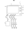
- FIG. 1 is a schematic explanatory diagram regarding the configuration of a high-frequency treatment device as an embodiment of the present invention.
- FIG. 2 is a block diagram showing functional elements of the high-frequency treatment device of FIG. 1.
- FIG. 1 is an explanatory diagram regarding a high frequency treatment method as an embodiment of the present invention.
- FIG. 4 is an explanatory diagram regarding a transition mode of the pulse width of a pulse signal for increasing electrode temperature.
- FIG. 4 is an explanatory diagram regarding a transition mode of the pulse width of a pulse signal for lowering the electrode temperature.
- a high-frequency treatment device 1 according to a first embodiment of the present invention shown in FIG. 1 is a device for performing a nerve block by partially heating a peripheral nerve with a high-frequency current.
- the high-frequency treatment device 1 includes a main body 10 (housing or casing), a first electrode 21, a second electrode 22, and a third electrode 23 connected to the main body 10.
- a connected return electrode plate 30 is provided.
- the three electrodes 21, 22, and 23 and the return electrode plate 30 connected to the main body 10 may not be components of the high-frequency treatment device 1 (or may be additional components).
- the main body 10 accommodates or supports components described below.
- a first electrode connector 11, a second electrode connector 12, and a third electrode connector 13 are provided, to which the first electrode 21, the second electrode 22, and the third electrode 23 are electrically connected, respectively, and , a return electrode plate connector 15 to which the return electrode plate 30 is electrically connected is provided.
- a touch panel type operation section 16 is provided at the upper front of the main body 10.
- the operation unit 16 includes a touch panel display 161 that accepts input operations such as various settings and displays various information, a button 162 that accepts operations to start and end treatment, and a control knob 163 for adjusting output power. has been done.
- target temperatures can be set for each of the first electrode 21, second electrode 22, and third electrode 23.
- temperatures in the range of 42° C. to 45° C. can be set discretely (for example, in 1° C. steps).
- a target voltage of the high-frequency voltage to be applied between at least two of the first electrode 21, the second electrode 22, the third electrode 23, and the return electrode plate 30 can be set.
- a handle 17 for carrying the main body 10 is provided at the top of the main body 10.
- a power connector and a power switch are provided on the back side of the main body 10 to connect to a commercial AC power source and receive power.
- Each of the first electrode 21, second electrode 22, and third electrode 23 is configured to be inserted into a human body, etc., which is a target for high-frequency treatment, and to flow a high-frequency current into the human body.
- each of the first electrode 21, the second electrode 22, and the third electrode 23 has a needle-tube shape that can be punctured into a human body, etc., and can also inject drugs etc. through the electrodes 21 to 23. It is composed of Most of each of the first electrode 21, second electrode 22, and third electrode 23 has insulating parts 212 to 232 coated with an insulating coating, except for non-insulated parts 211 to 231 at the tips, and high-frequency current is non-insulated. The signals are output from the insulating sections 211 to 231.
- Each of the first electrode 21, second electrode 22, and third electrode 23 includes, for example, a first thermocouple 213, a second thermocouple 223, and a Each third thermocouple 233 is provided.
- Each of the first electrode 21, the second electrode 22, and the third electrode 23 may have a shape other than that described above, for example, a rod shape inserted into a needle tube or a catheter. Further, each of the first thermocouple 213, the second thermocouple 223, and the third thermocouple 233 may be provided separately from each of the first electrode 21, the second electrode 22, and the third electrode 23. .
- the return electrode plate 30 is a flat electrode that is attached to the skin surface of a human body or the like to be treated, and at least one of the first electrode 21, second electrode 22, and third electrode 23 inserted therein. This is for passing a high frequency current between one electrode. That is, the return electrode plate 30 is a so-called monopolar plate and is used when a high frequency current is caused to flow.
- the return electrode plate 30 is electrically connected to the main body 10 via the return electrode cable 31 and the return electrode connector 15.
- the return electrode plate 30 is configured to have a rectangular flat plate shape, but the shape of the return electrode plate 30 may be other shapes.
- the high-frequency treatment device 1 includes, as functional elements, an output section 110, an output switching section 111, a voltage/current measurement section 112, a temperature measurement section 120, and a reference voltage generation section 121. , a temperature comparison section 122 , a main control section 141 , and a sub-control section 142 .
- the output unit 110 generates high frequency power (primary high frequency It is configured to output pulsed high-frequency power generated by generating a power signal) and turning on/off the primary high-frequency power based on a pulse signal (pulse width wp, pulse period Tp) from the main control unit 141. has been done.
- the output section 110 is connected to the first electrode connector 11, the second electrode connector 12, the third electrode connector 13, and the return electrode connector 15 via the output switching section 111, and in turn is connected to the first electrode 21, the second electrode 22, and the second electrode connector 15. It is connected to the three electrodes 23 and the return electrode plate 30 so as to be able to output pulsed power.
- the output unit 110 is composed of a known circuit including a transformer, thereby insulating the human body to be treated from the commercial AC power source.
- the output switching section 111 operates under the control of the main control section 141 and changes the electrical connection state between the output section 110 and the first electrode connector 11, second electrode connector 12, third electrode connector 13, and return electrode connector 15. Configured to switch.
- the output switching section 111 is composed of a circuit including a plurality of switches including semiconductor switches such as MOSFETs (Metal Oxide Semiconductor Field Effect Transistors) or reed relays, and includes an output section 110, a first electrode 21, a second electrode 22, and a plurality of switches. It is provided between the three electrodes 23 and the return electrode plate 30.
- MOSFETs Metal Oxide Semiconductor Field Effect Transistors
- the voltage/current measuring section 112 is composed of known circuits and the like, and is configured to measure the pulse current and pulse voltage output from the output section 110.
- the voltage/current measurement section 112 is configured to generate a voltage measurement signal according to the high frequency voltage generated by the output section 110 and a current measurement signal according to the high frequency current, and transmit them to the main control section 141. .
- the temperature measurement unit 120 is configured from a known circuit, etc., and generates a temperature measurement signal (for example, 25 mV /°C) and is configured to transmit it to each of the main control unit 141 and the temperature comparison unit 122.
- a temperature measurement signal for example, 25 mV /°C
- the reference voltage generation section 121 is composed of a known circuit, etc., receives the target temperature transmitted from the main control section 141, generates a reference voltage corresponding to the target temperature, and then outputs it to the temperature comparison section 122. configured to send.
- the temperature comparison unit 122 is configured from a known circuit, etc., receives the reference voltage transmitted from the reference voltage generation unit 121 and the measured temperature signal transmitted from the temperature measurement unit 120, and calculates the target temperature and temperature according to the reference voltage. It is configured to compare the measured temperatures according to the measured temperature signals and to transmit the temperature comparison result (difference voltage signal) to the main control section 141 and/or the sub control section 142.
- the main control unit 141 is composed of an arithmetic processing element such as a CPU, a storage element such as a ROM and/or a RAM, an I/O circuit, and the like.
- the main control unit 141 is configured to control the operations of the components of the high-frequency treatment device 1, such as the operation unit 16, the output unit 110, and the output switching unit 111, to perform high-frequency treatment.
- the main control unit 141 measures voltage, current, power, and impedance based on the voltage measurement signal and current measurement signal received from the voltage/current measurement unit 112, and displays the measured values on the touch panel display 161 along with the measured temperature. .
- the main control unit 141 When the target voltage is set through the operation unit 16, the main control unit 141 outputs the output from the output unit 110 in order to match the measured voltage according to the voltage measurement signal received from the voltage/current measurement unit 112 with the target voltage. is configured to control the high frequency power generated.
- the sub-control unit 142 is a known device that includes an arithmetic processing element such as a CPU, a storage element such as a ROM and/or a RAM, an I/O circuit, and a sawtooth wave transmitter and a comparator. It is composed of a PWM (Pulse Width Modulation) circuit, etc.
- the sub-control unit 142 compares the temperature comparison result (differential voltage signal) sent from the temperature comparison unit 122 with the sawtooth wave signal, generates a temperature control pulse signal, and sends it to the output unit 110.
- the sub-control section 142 (and the main control section 141) and the temperature comparison section 122 constitute a "control section" in the present invention.
- the output switching section 111, the voltage/current measurement section 112, the temperature measurement section 120, the reference voltage generation section 121, the temperature comparison section 122, and the sub-control section 142 are insulated from the commercial AC power supply in order to protect the human body to be treated. ing.
- the pulse width wp is set to the reference pulse width w0 in response to a touch operation of the start button on the operation unit 16, and each of the flags n1, m1, n2, and m2 is set to It is set to "0" (FIG. 3/STEP 100).
- the flag n1 is a flag indicating the extent to which the pulse width wp is increased from the reference pulse width w0.
- the flag m1 is a flag representing the time interval at which the pulse width wp is increased.
- the flag n2 is a flag representing the degree to which the pulse width wp is decreased from the reference pulse width w0.
- Flag m2 is a flag representing the time interval at which the pulse width wp is decreased.
- the main control section 141 outputs an output control signal and a pulse signal (pulse width wp, pulse period Tp) to the output section 110.
- the output unit 110 turns on/off the primary high-frequency power signal according to the output control signal, and the pulsed high-frequency power (secondary high-frequency power signal) is applied to the treatment target through the corresponding electrode.
- the frequency of the pulse signal is, for example, 1 Hz, 2 Hz, 5 Hz, or 10 Hz
- the pulse width is, for example, 5 ms, 10 ms, 20 ms, 30 ms, or 50 ms.
- the pulse signal is pulse width modulated within a range not exceeding the reference pulse width w0 for temperature control.
- the high-frequency treatment apparatus 1 having the above configuration, three types of output formats of pulse current to the treatment target are possible: monopolar output format, bipolar output format, and tripolar output format.
- the monopolar output format is an output format in which a pulse voltage is applied between any one of the first electrode 21, the second electrode 22, and the third electrode 23 and the return electrode plate 30.
- the bipolar output format is an output format in which a pulse voltage is applied between two of the first electrode 21, second electrode 22, and third electrode 23.
- the tripolar output format is an output format in which a pulse voltage is applied between any one of the first electrode 21, second electrode 22, and third electrode 23 and the remaining two electrodes.
- the temperature measurement unit 120 determines whether the first electrode 21, the second electrode 22, and the third electrode The temperature ⁇ of the corresponding electrode or its surroundings among the electrodes 23 is measured (FIG. 3/STEP 104). As described above, the temperature measurement section 120 is configured to generate a temperature measurement signal according to the measured temperature ⁇ , and transmit it to each of the main control section 141 and the temperature comparison section 122.
- the sub-control unit 142 determines that the measured temperature ⁇ is equal to or lower than the lower limit temperature ⁇ 0 ⁇ 1 (0 ⁇ 1) of the target temperature range based on the target temperature ⁇ 0. It is determined whether or not (FIG. 3/STEP 106).
- the sub-control unit 142 sets a flag indicating the time interval for increasing the pulse width wp. It is determined whether m1 is greater than or equal to the first designated value M1 (FIG. 3/STEP 110). Depending on the magnitude of the first designated value M1, the speed at which the pulse width wp increases is determined. Therefore, the first designated value M1 may be variably set depending on the rate of increase (d ⁇ /dt) (>0) of the measured temperature ⁇ .
- the sub-control unit 142 (or main control unit 141) increases the flag m1 by “1”, and then the main control unit 141 sets the treatment end condition. Sufficiency is determined (FIG. 3/STEP 130). On the other hand, if the determination result is positive (FIG. 3/STEP 110...YES), the sub-control unit 142 (or main control unit 141) resets the flag m1 to "0" and sets the pulse width wp. A flag n1 indicating the degree of increase is increased by "1" (FIG. 3/STEP 111).
- the sub-control unit 142 determines whether the flag n1 is equal to or greater than the first threshold value N1 (FIG. 3/STEP 113).
- the upper limit value of the pulse width wp is w0+N1 ⁇ w1, but the first threshold value is set so that the maximum value of the duty ratio w0+N1 ⁇ w1 ⁇ T (T is the pulse period) is within a predetermined range (for example, 50 to 70%).
- N1 may be set.
- the main control unit 141 determines whether the treatment end condition is satisfied (FIG. 3/STEP 130). On the other hand, if the determination result is positive (FIG. 3/STEP 113...YES), the sub-control unit 142 increases the pulse width wp by ⁇ w1 (FIG. 3/STEP 114). By repeating this process, the pulse width wp can be increased by an increase amount ⁇ w1 from the reference pulse width w0, as schematically shown in FIG.
- the rate of increase in the pulse width wp is determined depending on the magnitude of the increase ⁇ w1 in the pulse width wp. Therefore, the increase amount ⁇ w1 may be set variably depending on the rate of increase (d ⁇ /dt) (>0) of the measured temperature ⁇ . Specifically, the lower the rate of increase (d ⁇ /dt) of the measured temperature ⁇ , the larger the increase ⁇ w1 is set, and the higher the rate of increase (d ⁇ /dt) of the measured temperature ⁇ , the smaller the increase ⁇ w1. good.
- the main control unit 141 determines the sufficiency of the treatment end condition (FIG. 3/STEP 130).
- the treatment end condition is that the elapsed time from the start of pulse signal output and/or the elapsed time or cumulative time since the measured temperature ⁇ became equal to or higher than the target temperature ⁇ 0 has reached a specified time, or A condition such as that the number of outputs has reached a specified number may be adopted.
- the main control section 141 outputs an output control signal to the output section 110, and the sub control section 142 outputs a pulse signal with a pulse width wp to the output section. 110, and the output unit 110 supplies the output control signal and the pulse signal with high-frequency pulse power to the treatment target through the corresponding electrodes (FIG. 3/STEP 102). If the determination result is positive (FIG. 3/STEP 130...YES), the series of processes ends.
- the sub-control unit 142 (or main control unit 141) It is determined whether the measured temperature ⁇ is equal to or higher than the upper limit temperature ⁇ 0+ ⁇ 2 (0 ⁇ 2) of the target temperature range based on the target temperature ⁇ 0 (FIG. 3/STEP 108).
- ⁇ 1 and ⁇ 2 that define the target temperature range may be the same or different.
- ⁇ 1 and ⁇ 2 are set to appropriate values so that the pulse width wp is not changed too frequently depending on the measured temperature ⁇ .
- the main control unit 141 determines whether the treatment end condition is satisfied (FIG. 3/STEP 130).
- the sub-control unit 142 displays a time interval for decreasing the pulse width wp. It is determined whether the flag m2 is greater than or equal to the second specified value M2 (FIG. 3/STEP 120). Depending on the magnitude of the second designated value M2, the speed at which the pulse width wp decreases is determined. Therefore, the second specified value M2 may be variably set depending on the rate of increase (d ⁇ /dt) (>0) of the measured temperature ⁇ .
- the sub-control unit 142 (or main control unit 141) increases the flag m2 by “1”, and then the main control unit 141 sets the treatment end condition. Sufficiency is determined (FIG. 3/STEP 130). On the other hand, if the determination result is positive (FIG. 3/STEP 120...YES), the sub-control unit 142 (or main control unit 141) resets the flag m2 to "0" and sets the pulse width wp. A flag n2 indicating the degree of reduction is increased by "1" (FIG. 3/STEP 121).
- the sub-control unit 142 determines whether the flag n2 is equal to or greater than the second threshold value N2 (FIG. 3/STEP 123).
- the first threshold value N1 may be set so that ⁇ T (T is the pulse period) is included in a predetermined range (for example, 20 to 40%).
- the first threshold value N1 and the second threshold value N2 may be the same or different.
- the main control unit 141 determines whether the treatment end condition is satisfied (FIG. 3/STEP 130). On the other hand, if the determination result is positive (FIG. 3/STEP 123...YES), the sub-control unit 142 reduces the pulse width wp by ⁇ w2 (FIG. 3/STEP 124). By repeating this process, the pulse width wp can be reduced by a reduction width ⁇ w2, as schematically shown in FIG.
- the speed at which the pulse width wp decreases is determined depending on the magnitude of the decrease width ⁇ w2 of the pulse width wp. Therefore, the decrease width ⁇ w2 may be set variably depending on the rate of increase (d ⁇ /dt) (>0) of the measured temperature ⁇ . Specifically, the lower the rate of increase (d ⁇ /dt) of the measured temperature ⁇ is, the smaller the decrease width ⁇ w2 is set, and the higher the rate of increase (d ⁇ /dt) of the measured temperature ⁇ , the larger the decrease width ⁇ w2 is set. good. After the measured temperature ⁇ changes from increasing to decreasing, the decrease width ⁇ w2 may be changed to "0".
- the main control unit 141 determines the sufficiency of the treatment end condition (FIG. 3/STEP 130). If the determination result is negative (FIG. 3/STEP 130...NO), the main control section 141 outputs an output control signal to the output section 110, and the sub control section 142 outputs a pulse signal with a pulse width wp to the output section. 110, and the output unit 110 supplies the output control signal and the pulse signal with high-frequency pulse power to the treatment target through the corresponding electrodes (FIG. 3/STEP 102). If the determination result is positive (FIG. 3/STEP 130...YES), the series of processes ends.
- the first electrode 21 is set such that the measured temperature ⁇ is included in the target temperature range [ ⁇ 0- ⁇ 1, ⁇ 0+ ⁇ 2] based on the target temperature ⁇ 0 set through the operation unit 16.
- the high frequency power supplied to the treatment target through at least one of the second electrode 22 and the third electrode 23 is controlled. Specifically, when the measured temperature ⁇ of the relevant electrode is lower than the lower limit temperature ⁇ 0- ⁇ 1 of the target temperature range, the pulse width wp of the pulse signal is gradually increased, so that the measured temperature ⁇ is lower than the lower limit temperature ⁇ 0.
- the high frequency power output to the corresponding electrode is gradually increased so that it becomes equal to or greater than - ⁇ 1 (see FIG.
- the at least one electrode and its surrounding area are maintained near the target temperature ⁇ 0, and the measurement temperature ⁇ can be appropriately controlled from the viewpoint of thermal coagulation and/or denaturation of the living tissue.
- the high-frequency treatment device 1 has three electrode connectors (the first electrode connector 11, the second electrode connector 13) corresponding to the three electrodes (the first electrode connector 11, the second electrode connector 12, and the third electrode connector 13). 12 and a third electrode connector 13), the high-frequency treatment device 1 may have two electrode connectors corresponding to two electrodes, and the high-frequency treatment device 1 can correspond to four or more electrodes. It may have four or more electrode connectors.
- At least two of the electrodes connected to the electrode connector may be configured as pad-type electrodes (electrode pads) that are attached to the surface of the human body and apply high-frequency power from the outside to the inside of the human body.
Landscapes
- Health & Medical Sciences (AREA)
- Surgery (AREA)
- Engineering & Computer Science (AREA)
- Life Sciences & Earth Sciences (AREA)
- Biomedical Technology (AREA)
- Molecular Biology (AREA)
- Nuclear Medicine, Radiotherapy & Molecular Imaging (AREA)
- Plasma & Fusion (AREA)
- Physics & Mathematics (AREA)
- Heart & Thoracic Surgery (AREA)
- Medical Informatics (AREA)
- Otolaryngology (AREA)
- Animal Behavior & Ethology (AREA)
- General Health & Medical Sciences (AREA)
- Public Health (AREA)
- Veterinary Medicine (AREA)
- Surgical Instruments (AREA)
- Control Of Heat Treatment Processes (AREA)
Priority Applications (1)
| Application Number | Priority Date | Filing Date | Title |
|---|---|---|---|
| JP2024516319A JPWO2023204284A1 (https=) | 2022-04-22 | 2023-04-20 |
Applications Claiming Priority (2)
| Application Number | Priority Date | Filing Date | Title |
|---|---|---|---|
| JP2022070975 | 2022-04-22 | ||
| JP2022-070975 | 2022-04-22 |
Publications (1)
| Publication Number | Publication Date |
|---|---|
| WO2023204284A1 true WO2023204284A1 (ja) | 2023-10-26 |
Family
ID=88419924
Family Applications (1)
| Application Number | Title | Priority Date | Filing Date |
|---|---|---|---|
| PCT/JP2023/015837 Ceased WO2023204284A1 (ja) | 2022-04-22 | 2023-04-20 | 高周波処置装置 |
Country Status (3)
| Country | Link |
|---|---|
| JP (1) | JPWO2023204284A1 (https=) |
| TW (1) | TW202400091A (https=) |
| WO (1) | WO2023204284A1 (https=) |
Citations (2)
| Publication number | Priority date | Publication date | Assignee | Title |
|---|---|---|---|---|
| JP2007537000A (ja) * | 2004-05-14 | 2007-12-20 | カーディマ・インコーポレイテッド | 凝血塊を低減するマルチ・チャネルでrfエネルギー供給をするシステムおよび方法 |
| WO2020262279A1 (ja) * | 2019-06-25 | 2020-12-30 | 株式会社トップ | 高周波処置装置および高周波処置方法 |
-
2023
- 2023-04-20 WO PCT/JP2023/015837 patent/WO2023204284A1/ja not_active Ceased
- 2023-04-20 JP JP2024516319A patent/JPWO2023204284A1/ja active Pending
- 2023-04-21 TW TW112114952A patent/TW202400091A/zh unknown
Patent Citations (2)
| Publication number | Priority date | Publication date | Assignee | Title |
|---|---|---|---|---|
| JP2007537000A (ja) * | 2004-05-14 | 2007-12-20 | カーディマ・インコーポレイテッド | 凝血塊を低減するマルチ・チャネルでrfエネルギー供給をするシステムおよび方法 |
| WO2020262279A1 (ja) * | 2019-06-25 | 2020-12-30 | 株式会社トップ | 高周波処置装置および高周波処置方法 |
Also Published As
| Publication number | Publication date |
|---|---|
| JPWO2023204284A1 (https=) | 2023-10-26 |
| TW202400091A (zh) | 2024-01-01 |
Similar Documents
| Publication | Publication Date | Title |
|---|---|---|
| EP3111873B1 (en) | Electrosurgical generator for minimizing neuromuscular stimulation | |
| US9585709B2 (en) | Square wave for vessel sealing | |
| US9522038B2 (en) | Crest factor enhancement in electrosurgical generators | |
| AU2014203332B2 (en) | Systems and methods for operating an electrosurgical generator | |
| US9770283B2 (en) | Systems and methods for improving efficiency of electrosurgical generators | |
| EP2301464A1 (en) | Electrosurgical generator user interface | |
| US9522039B2 (en) | Crest factor enhancement in electrosurgical generators | |
| WO2023204284A1 (ja) | 高周波処置装置 | |
| WO2023204282A1 (ja) | 高周波処置装置 | |
| KR102312773B1 (ko) | 전력 값 차이 기반 제어에 의한 고주파 치료장치 | |
| KR102310791B1 (ko) | 전압 값 차이 기반 제어에 의한 고주파 치료장치 | |
| Rafsanzani et al. | A Modified Electrosurgery Unit Based on High Frequency Design with Monopolar and Bipolar Method | |
| WO2024042964A1 (ja) | 高周波処置装置 | |
| JP7695564B2 (ja) | 高周波処置装置 | |
| US10537377B2 (en) | Electrosurgical generator with half-cycle power regulation | |
| CN114618083A (zh) | 一种新型自适应射频变频皮下组织辐射体积控制方法 | |
| EP4725432A1 (en) | High-frequency treatment device and high-frequency treatment method | |
| WO2024029416A1 (ja) | 高周波処置装置 | |
| TW202435819A (zh) | 高頻處理裝置及高頻處理方法 | |
| JPH0663059A (ja) | 医療用高周波焼灼装置 |
Legal Events
| Date | Code | Title | Description |
|---|---|---|---|
| 121 | Ep: the epo has been informed by wipo that ep was designated in this application |
Ref document number: 23791932 Country of ref document: EP Kind code of ref document: A1 |
|
| WWE | Wipo information: entry into national phase |
Ref document number: 2024516319 Country of ref document: JP |
|
| NENP | Non-entry into the national phase |
Ref country code: DE |
|
| 122 | Ep: pct application non-entry in european phase |
Ref document number: 23791932 Country of ref document: EP Kind code of ref document: A1 |