WO2023199968A1 - Stop indicator - Google Patents
Stop indicator Download PDFInfo
- Publication number
- WO2023199968A1 WO2023199968A1 PCT/JP2023/014976 JP2023014976W WO2023199968A1 WO 2023199968 A1 WO2023199968 A1 WO 2023199968A1 JP 2023014976 W JP2023014976 W JP 2023014976W WO 2023199968 A1 WO2023199968 A1 WO 2023199968A1
- Authority
- WO
- WIPO (PCT)
- Prior art keywords
- base member
- stop indicator
- leg
- base
- grounding
- Prior art date
Links
- 229920001971 elastomer Polymers 0.000 claims description 6
- 239000000806 elastomer Substances 0.000 claims description 6
- 239000000463 material Substances 0.000 claims description 6
- 239000011347 resin Substances 0.000 description 3
- 229920005989 resin Polymers 0.000 description 3
- 229920002943 EPDM rubber Polymers 0.000 description 2
- 238000005452 bending Methods 0.000 description 2
- 238000010586 diagram Methods 0.000 description 2
- 238000000034 method Methods 0.000 description 2
- 238000012986 modification Methods 0.000 description 2
- 230000004048 modification Effects 0.000 description 2
- 238000009434 installation Methods 0.000 description 1
- 230000000630 rising effect Effects 0.000 description 1
- 238000000926 separation method Methods 0.000 description 1
Images


Classifications
-
- B—PERFORMING OPERATIONS; TRANSPORTING
- B60—VEHICLES IN GENERAL
- B60Q—ARRANGEMENT OF SIGNALLING OR LIGHTING DEVICES, THE MOUNTING OR SUPPORTING THEREOF OR CIRCUITS THEREFOR, FOR VEHICLES IN GENERAL
- B60Q7/00—Arrangement or adaptation of portable emergency signal devices on vehicles
-
- G—PHYSICS
- G09—EDUCATION; CRYPTOGRAPHY; DISPLAY; ADVERTISING; SEALS
- G09F—DISPLAYING; ADVERTISING; SIGNS; LABELS OR NAME-PLATES; SEALS
- G09F13/00—Illuminated signs; Luminous advertising
- G09F13/16—Signs formed of or incorporating reflecting elements or surfaces, e.g. warning signs having triangular or other geometrical shape
-
- G—PHYSICS
- G09—EDUCATION; CRYPTOGRAPHY; DISPLAY; ADVERTISING; SEALS
- G09F—DISPLAYING; ADVERTISING; SIGNS; LABELS OR NAME-PLATES; SEALS
- G09F7/00—Signs, name or number plates, letters, numerals, or symbols; Panels or boards
- G09F7/18—Means for attaching signs, plates, panels, or boards to a supporting structure
Definitions
- a stop indicator is known that is placed on the road near a vehicle stopped on the road in order to notify that a vehicle such as a car is stopped on the road.
- the stop indicator has legs and a triangular frame that stands on the legs, and is configured so that the legs and the triangular frame can be folded up so that they can be stored compactly when not in use. (For example, Patent Documents 1 and 2).
- the second leg member has a grooved cross-sectional shape to improve rigidity, the second base member does not become bulky in the stored position.
- the hypotenuse members 22 and 24 extend horizontally in the same direction as the bottom member 16 around the center axis of the shaft portions 18 and 20 relative to the bottom member 16, respectively, 1 to 3, the light reflecting portions 22A and 24A overlap each other in the front and back, and the fluorescent portions 22B and 24B overlap each other in the front and back with the fluorescent portion 16B sandwiched between the fluorescent portions 16B of the bottom member 16.
- it forms both the left and right hypotenuses of the triangular display section 14, and is rotatable between the expanded position (use position) where it cooperates with the bottom member 16 to form an equilateral triangular frame. There is.
- the stop indicator 10 in the retracted state with the pair of second leg members 42 folded is suitable for use on a flat road surface, etc., and the stop indicator 10 can be installed stably on the road.
- the use of the stop indicator 10 with the pair of second leg members 42 expanded is suitable for use on rough terrain.
- the stop indicator 10 Even if the one leg member 34 and the second leg member 42 are provided, the compactness when not in use is not hindered.
- a rectangular parallelepiped-shaped grounding member 52 is attached to the grounding portion (free end) 42C of each second leg member 42 so as to be foldable and storable.
- Guide recesses 54 are formed on the left and right side surfaces of the grounding member 52, respectively.
- a sliding protrusion 56 that engages with the guide recess 54 is formed on the grounding portion 42C.
- the maximum span of the front and rear grounding points of the stop indicator 10 is further expanded by the front and rear grounding members 52 in the use position, and the stop indicator 10 becomes even more difficult to fall back and forth.
Landscapes
- Physics & Mathematics (AREA)
- Engineering & Computer Science (AREA)
- General Physics & Mathematics (AREA)
- Theoretical Computer Science (AREA)
- Geometry (AREA)
- Mechanical Engineering (AREA)
- Refuge Islands, Traffic Blockers, Or Guard Fence (AREA)
Abstract
[Problem] To provide a stop indicator that is stably installed on a road, hardly knocked over by wind, and folded compactly when not in use. [Solution] The present invention comprises: a first base member (12) that extends horizontally and on which a triangular indicator (14) is disposed; a second base member (30) that extends horizontally and is connected to the first base member (12) so as to be rotatable between a retracted position where the second base member extends in the same direction as the extension direction of the first base member (12) and a use position where the second base member extends in a direction orthogonal to the extension direction of the first base member (12); a pair of first leg members (34) foldably provided at both ends of the first base member (12); and a pair of second leg members (42) foldably provided at both ends of the second base member (30).
Description
本発明は停止表示器に関する。
The present invention relates to a stop indicator.
自動車等の車両が路上に停車していることを通知するために、路上に停車している車両の近傍の路上に置かれる停止表示器は知られている。停止表示器は、脚部及び脚部上に立設された三角枠部を有し、不使用時にはコンパクトに格納できるように、脚部及び三角枠部がそれぞれ折り畳ためるように構成されている(例えば、特許文献1、2)。
A stop indicator is known that is placed on the road near a vehicle stopped on the road in order to notify that a vehicle such as a car is stopped on the road. The stop indicator has legs and a triangular frame that stands on the legs, and is configured so that the legs and the triangular frame can be folded up so that they can be stored compactly when not in use. (For example, Patent Documents 1 and 2).
停止表示器は、路上に倒れ難く安定して設置され、風によって倒され難い耐風性が高いことと、不使用時には自動車のトランクルーム等に大きいスペースを要することなく収納されるようにコンパクトに折り畳まれることとを要求される。
The stop indicator is installed stably on the road so that it does not fall over, has high wind resistance so that it does not easily fall over, and when not in use, it can be folded compactly so that it can be stored in the trunk of a car without requiring a large space. be asked to do something.
本発明は、以上の背景に鑑み、路上に安定して設置され、風によって倒され難く、しかも不使用時にはコンパクトに折り畳まれる停止表示器を提供することを課題とする。
In view of the above background, it is an object of the present invention to provide a stop indicator that is stably installed on the road, is difficult to be knocked over by wind, and is foldable into a compact size when not in use.
上記課題を解決するために本発明のある態様は、三角形状をなす停止表示器(10)であって、水平方向に延在する直線状をなす第1ベース部材(12)と、前記第1ベース部材の上面に立設された三角表示部(14)と、水平方向に延在する直線状をなし、前記第1ベース部材の延在方向と同方向に延在する格納位置と前記第1ベース部材の延在方向に直交する方向に延在する使用位置との間を回動可能に、前記第1ベース部材の中央部に鉛直な軸線周りに回動可能に連結された中央部を含む第2ベース部材(30)と、前記第1ベース部材と重なり合う格納位置と、前記第1ベース部材より垂下する使用位置との間を回動可能であるように、前記第1ベース部材の両端部に、前記第1ベース部材に直交する水平な軸線周りに回動可能に連結された基端部(35)を含む1対の第1脚部材(34)と、前記第2ベース部材と重なり合う格納位置と前記第2ベース部材の端部から外方に張り出した使用位置との間を回動可能であるように、前記第2ベース部材の両端部に、前記第2ベース部材に直交する水平な軸線周りに回動可能に連結された基端部(43)を含む1対の第2脚部材(42)とを有する。
In order to solve the above problems, an aspect of the present invention is a stop indicator (10) having a triangular shape, which includes a first base member (12) having a linear shape extending in the horizontal direction; A triangular display section (14) erected on the upper surface of the base member, a storage position extending in a straight line extending horizontally in the same direction as the first base member; a central portion rotatably connected to the central portion of the first base member around a vertical axis so as to be rotatable between a use position extending in a direction perpendicular to the extending direction of the base member; A second base member (30) and both ends of the first base member are rotatable between a stored position overlapping the first base member and a use position hanging down from the first base member. a pair of first leg members (34) including a proximal end (35) rotatably connected around a horizontal axis perpendicular to the first base member; and a retractable leg member (34) overlapping the second base member. A horizontal line perpendicular to the second base member is provided at each end of the second base member so as to be rotatable between a position and a use position projecting outward from the end of the second base member. It has a pair of second leg members (42) including a base end (43) connected to be rotatable around an axis.
この態様によれば、停止表示器は、路上に倒れ難く安定して設置され、風によって倒され難く、しかも不使用時にはコンパクトに折り畳まれる。
According to this aspect, the stop indicator is stably installed on the road without being easily knocked over, is not easily knocked over by wind, and is folded compactly when not in use.
上記の態様において、各第2脚部材は、前記基端部を含む直線状の主部(42A)と、前記主部の遊端部の側に前記主部に対して折曲可能に可撓性を有して接続された接地部(42B)とを有してもよい。
In the above aspect, each second leg member includes a linear main part (42A) including the base end part, and a flexible end part (42A) on the free end side of the main part so as to be bendable with respect to the main part. It may also have a grounding portion (42B) that is connected to the grounding portion 42B.
この態様によれば、各第2脚部材の接地部は路面の傾斜等に倣って主部に対して任意の角度を持つことができ、使用状態での停止表示器の路上設置の安定性が向上する。
According to this aspect, the ground contact part of each second leg member can have an arbitrary angle with respect to the main part following the slope of the road surface, etc., and the stability of the roadside installation of the stop indicator during use is improved. improves.
上記の態様において、各接地部にエラストマ材による第1接地シート(44)が設けられていてもよい。
In the above embodiment, each grounding portion may be provided with a first grounding sheet (44) made of an elastomer material.
この態様によれば、使用状態での停止表示器の路上設置の安定性が更に向上する。
According to this aspect, the stability of installing the stop indicator on the road during use is further improved.
上記の態様において、前記格納位置において下向きになる各第2脚部材の表面に、エラストマ材による第2接地シート(46)が設けられていてもよい。
In the above embodiment, a second grounding sheet (46) made of an elastomer material may be provided on the surface of each second leg member that faces downward in the storage position.
この態様によれば、第2脚部材が格納位置にある状態での停止表示器の路上設置において、停止表示器の路上設置の安定性が更に向上する。
According to this aspect, when the stop indicator is installed on the road with the second leg member in the retracted position, the stability of the stop indicator on the road is further improved.
上記の態様において、前記第2ベース部材は横断面形状が矩形の棒状部材により構成され、各第2脚部材は、収納位置に於いて、前記第2ベース部材を受容する溝形断面形状を有していてもよい。
In the above aspect, the second base member is constituted by a rod-like member having a rectangular cross-sectional shape, and each second leg member has a groove-shaped cross-sectional shape to receive the second base member in the storage position. You may do so.
この態様によれば、第2脚部材が溝形断面形状を有して剛性の向上が図られても、収納位置に於いて第2ベース部材が嵩張ることがない。
According to this aspect, even if the second leg member has a grooved cross-sectional shape to improve rigidity, the second base member does not become bulky in the stored position.
上記の態様において、前記第2ベース部材は自身の延在方向に長い長孔(48)を有し、前記第2脚部材は前記長孔に回動且つ摺動可能に係合する軸部(40)を有し、前記第2ベース部材の延在方向に対する摺動により前記第2ベース部材と重なり合う各第2脚部材は、前記基端部が前記第2ベース部材の延在方向に摺動可能であってもよい。
In the above aspect, the second base member has an elongated hole (48) extending in the direction in which the second base member extends, and the second leg member has a shaft portion (48) that rotatably and slidably engages with the elongated hole. 40), and each of the second leg members overlaps the second base member by sliding in the extending direction of the second base member, and the base end portion thereof is slidable in the extending direction of the second base member. It may be possible.
この態様によれば、第2脚部材がコンパクトに格納される。
According to this aspect, the second leg member is stored compactly.
上記の態様において、各第1脚部材及び各第2脚部材は、それぞれの格納位置にある時に、上下に重なり合うよう格納されてもよい。
In the above embodiment, each of the first leg members and each of the second leg members may be stored so as to overlap one another when in their respective storage positions.
この態様によれば、第1脚部材及び第2脚部材がコンパクトに格納される。
According to this aspect, the first leg member and the second leg member are stored compactly.
上記の態様において、更に、前記第1ベース部材に固定され、前記三角表示部の底辺をなす底辺部材(16)と、前記底辺部材に前後に互いに重なり合う位置する格納位置と前記三角表示部の両斜辺を形成する展開位置との間で回動可能に、前記底辺部材の両端に、前記第1ベース部材に直交する水平な軸線周りに回動可能に連結された基端(23)を含む1対の斜辺部材(24)とを有していてもよい。
In the above aspect, the invention further includes a bottom member (16) fixed to the first base member and forming the bottom of the triangular display section, and a storage position and the triangular display section located on the bottom member so as to overlap each other in the front and back. 1 including a base end (23) rotatably connected to both ends of the base member to be rotatable about a horizontal axis perpendicular to the first base member, the base member being rotatable between a deployed position forming an oblique side; It may also have a pair of oblique side members (24).
この態様によれば、三角表示部がコンパクトに格納される。
According to this aspect, the triangular display section is stored compactly.
以上の態様によれば、停止表示器は、路上に安定して設置され、風によって倒され難く、しかも不使用時にはコンパクトに折り畳まれる。
According to the above aspect, the stop indicator is stably installed on the road, is not easily knocked over by wind, and is folded compactly when not in use.
(実施形態1)
実施形態1による停止表示器を、図1~図6を参照して説明する。 (Embodiment 1)
A stop indicator according to Embodiment 1 will be described with reference to FIGS. 1 to 6.
実施形態1による停止表示器を、図1~図6を参照して説明する。 (Embodiment 1)
A stop indicator according to Embodiment 1 will be described with reference to FIGS. 1 to 6.
停止表示器10は第1ベース部材12を有する。第1ベース部材12は、左右方向に水平に延在する直線状の、換言すると、帯板状の主部12A及び主部12Aの左右の各端部12Dから直角に垂下された短片部12Bを有する。尚、第1ベース部材12及び以下に説明する停止表示器10を構成する各部材は樹脂成形品であってよい。
The stop indicator 10 has a first base member 12. The first base member 12 has a linear main part 12A extending horizontally in the left-right direction, in other words, a strip-like main part 12A, and a short piece part 12B hanging at right angles from each of the left and right ends 12D of the main part 12A. have Incidentally, each member constituting the first base member 12 and the stop indicator 10 described below may be a resin molded product.
第1ベース部材12の主部12Aの上部には三角表示部14が立設される。三角表示部14は、主部12Aの上面に固定され、左右方向に延在して三角表示部14の底辺をなす底辺部材16と、底辺部材16の両端に、各々、ピン状の軸部18、20により主部12Aに直交して前後方向に延在する水平な軸線周り回動可能に連結された基端23、25を含む左右1対の斜辺部材22、24とを有する。
A triangular display portion 14 is erected above the main portion 12A of the first base member 12. The triangular display section 14 includes a bottom member 16 that is fixed to the upper surface of the main section 12A and extends in the left-right direction to form the bottom of the triangular display section 14, and a pin-shaped shaft section 18 at each end of the bottom member 16. , 20 have a pair of left and right hypotenuse members 22, 24 including base ends 23, 25 connected rotatably about a horizontal axis extending in the front-rear direction and perpendicular to the main portion 12A.
底辺部材16及び左右の斜辺部材22、24は、各々、三角表示部14の各辺をなす帯板状の光反射部16A、22A、24A及び光反射部16A、22A、24Aの各々の内辺に沿って延在する蛍光部16B、22B、22Bを有する。左側の斜辺部材24は底辺部材16の前側に配置されている。右側の斜辺部材26は底辺部材16の後側に配置されている。
The bottom member 16 and the left and right oblique members 22 and 24 are the inner sides of the band-shaped light reflecting portions 16A, 22A, 24A and the light reflecting portions 16A, 22A, 24A forming each side of the triangular display portion 14, respectively. It has fluorescent parts 16B, 22B, and 22B extending along. The left oblique side member 24 is arranged in front of the bottom side member 16. The right side oblique member 26 is arranged on the rear side of the bottom member 16.
斜辺部材22、24は、図4及び図5に示されているように、各々、底辺部材16に対する軸部18、20の中心軸線周りに、底辺部材16と同方向に水平に延在し、光反射部22A、24Aが前後に互いに重なり合い、且つ蛍光部22B、24Bが底辺部材16の蛍光部16Bの前後に蛍光部16Bを挟んで前後に互いに重なり合う格納位置と、図1~図3に示されているように、三角表示部14の左右の両斜辺を形成し、底辺部材16と協働して正三角形の枠体をなす展開位置(使用位置)との間を回動可能になっている。
As shown in FIGS. 4 and 5, the hypotenuse members 22 and 24 extend horizontally in the same direction as the bottom member 16 around the center axis of the shaft portions 18 and 20 relative to the bottom member 16, respectively, 1 to 3, the light reflecting portions 22A and 24A overlap each other in the front and back, and the fluorescent portions 22B and 24B overlap each other in the front and back with the fluorescent portion 16B sandwiched between the fluorescent portions 16B of the bottom member 16. As shown, it forms both the left and right hypotenuses of the triangular display section 14, and is rotatable between the expanded position (use position) where it cooperates with the bottom member 16 to form an equilateral triangular frame. There is.
つまり、斜辺部材22、24は、底辺部材16に対する軸部18、20の中心軸線周りの回動により、上述の格納位置及び展開位置のいずれか一方の位置に選択的に位置することができる。
In other words, the hypotenuse members 22 and 24 can be selectively positioned in one of the above-mentioned storage position and deployed position by rotating the shaft parts 18 and 20 about the central axes with respect to the bottom member 16.
斜辺部材24は蛍光部24Bにルーバ状に突出形成された係止片部27を有する。斜辺部材22、24は、図2に示されているように、展開位置において、係止片部27が蛍光部22Bの内縁に係脱可能に当接することにより、上述の展開位置の状態を維持する。
The oblique side member 24 has a locking piece 27 formed in a louver-like protrusion on the fluorescent portion 24B. As shown in FIG. 2, the oblique side members 22 and 24 maintain the above-mentioned state in the deployed position by the locking piece portion 27 removably abutting on the inner edge of the fluorescent portion 22B in the deployed position. do.
第1ベース部材12の主部12Aの下側には第2ベース部材30が設けられている。第2ベース部材30は、横断面形状が矩形の、換言すると矩形の箱形断面形状を有する棒状部材により、水平方向に延在する直線状に構成されている。第2ベース部材30は、第1ベース部材12の長手方向の中央部12Cに、ピン状の軸部28により鉛直な軸線周りに回動可能に連結された長手方向の中央部30Aを含む。つまり、第1ベース部材12と第2ベース部材30とは、長手方向の中央部12C、中央部30A同士を鉛直な軸部28によって互い回動可能に連結されている。
A second base member 30 is provided below the main portion 12A of the first base member 12. The second base member 30 is a rod-shaped member having a rectangular cross-sectional shape, in other words, a rectangular box-shaped cross-sectional shape, and is configured in a linear shape extending in the horizontal direction. The second base member 30 includes a longitudinal center portion 30A that is rotatably connected to the longitudinal center portion 12C of the first base member 12 by a pin-shaped shaft portion 28 around a vertical axis. That is, the first base member 12 and the second base member 30 are rotatably connected to each other by the vertical shaft portion 28 at the longitudinal center portion 12C and the center portion 30A.
第2ベース部材30は、軸部28の中心軸線周りに、図4及び図5に示されているように、第1ベース部材12の主部12Aの延在方向と同方向(左右方向)に延在して主部12Aの下側において主部12Aと重なり合う格納位置と、図1~図3に示されているように、主部12Aの延在方向に直交する前後方向に延在する使用位置との間を回動可能になっている。
The second base member 30 extends around the central axis of the shaft portion 28 in the same direction (left-right direction) as the extending direction of the main portion 12A of the first base member 12, as shown in FIGS. 4 and 5. A storage position that extends and overlaps the main part 12A on the lower side of the main part 12A, and a use position that extends in the front-back direction perpendicular to the extending direction of the main part 12A, as shown in FIGS. 1 to 3. It is possible to rotate between positions.
第1ベース部材12と第2ベース部材30とは略同じ長手方向の長さを有する。より詳細には、第2ベース部材30は、上述の格納位置において、第1ベース部材12の主部12Aよりも外方にはみ出さないように、主部12Aの長手方向の長さを超える長手方向の長さを有することがなく、主部12Aの長手方向の長さよりも少し短い長手方向の長さを有する。これにより、第2ベース部材30が格納状態での停止表示器10のコンパクト性が確保される。
The first base member 12 and the second base member 30 have substantially the same length in the longitudinal direction. More specifically, the second base member 30 has a longitudinal length that exceeds the longitudinal length of the main portion 12A of the first base member 12 so as not to protrude outward beyond the main portion 12A of the first base member 12 in the above-mentioned storage position. It does not have a length in the direction, but has a length in the longitudinal direction that is slightly shorter than the length in the longitudinal direction of the main portion 12A. This ensures the compactness of the stop indicator 10 when the second base member 30 is in the retracted state.
第1ベース部材12の主部12Aの長手方向の両端部12Dには、対応する短片部12Bの内側においてピン状の軸部32(図6参照)により主部12Aに直交する水平な前後方向の軸線周りに回動可能に連結された基端部34Aを含む左右1対の第1脚部材34が設けられている。
At both ends 12D in the longitudinal direction of the main part 12A of the first base member 12, a pin-shaped shaft part 32 (see FIG. 6) is attached to the inside of the corresponding short piece part 12B so that a horizontal front-rear direction perpendicular to the main part 12A is provided. A pair of left and right first leg members 34 including a base end portion 34A rotatably connected around an axis are provided.
各第1脚部材34は、軸部32の中心軸線周りに、図6(A)に示されているように、第1ベース部材12の主部12Aの下方において主部12Aと重なり合う格納位置と、図6(B)に示されているように、主部12Aの端部より鉛直に垂下する使用位置との間を回動可能になっている。つまり、各第1脚部材34は第1ベース部材12の対応する端部12Dに折り畳み可能に設けられている。
Each first leg member 34 is positioned around the central axis of the shaft portion 32 at a storage position where it overlaps the main portion 12A below the main portion 12A of the first base member 12, as shown in FIG. 6(A). , as shown in FIG. 6(B), it is rotatable between a use position where it hangs down vertically from the end of the main portion 12A. That is, each first leg member 34 is foldably provided at the corresponding end 12D of the first base member 12.
各第1脚部材34は係合孔36を有する。各第1脚部材34は、図6(B)に示されているように、上述の使用位置において、係合孔36が短片部12Bに形成されている突部38に嵌合することにより、上述の使用位置を維持する。
Each first leg member 34 has an engagement hole 36. As shown in FIG. 6(B), each first leg member 34 has an engagement hole 36 that fits into a protrusion 38 formed in the short piece portion 12B in the above-mentioned use position. Maintain the usage position described above.
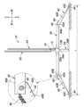
第2ベース部材30の長手方向の両端部30Bには、1対の第2脚部材42が設けられている。各第2脚部材42は、図3の部分拡大図に示されているように、第2ベース部材30の対応する端部30Bに設けられた軸受孔31に係合するピン状の軸部40により、第2ベース部材30に直交する水平な軸線周りに回動可能に連結された基端部42Aを含む。つまり、各第2脚部材42は第2ベース部材30の対応する端部30Bに折り畳み可能に設けられている。
A pair of second leg members 42 are provided at both ends 30B of the second base member 30 in the longitudinal direction. As shown in the partially enlarged view in FIG. The base end portion 42A is rotatably connected to the second base member 30 about a horizontal axis perpendicular to the second base member 30. That is, each second leg member 42 is foldably provided at the corresponding end 30B of the second base member 30.
各第2脚部材42は、軸部40の中心軸線周りに、図4及び図5に示されているように、第2ベース部材30の下側において、格納位置にある第1脚部材34を挟んで第2ベース部材30と重なり合う格納位置と、図1及び図2に示されているように、第2ベース部材30の対応する端部30Bから外方に張り出した使用位置との間を回動可能になっている。
Each of the second leg members 42 extends around the central axis of the shaft portion 40, as shown in FIGS. 4 and 5, on the lower side of the second base member 30. It rotates between a stored position in which the second base member 30 overlaps with the second base member 30, and a use position in which the second base member 30 projects outward from the corresponding end 30B, as shown in FIGS. 1 and 2. It is possible to move.
図3の部分拡大図に示されているように、第2脚部材42は、第2脚部材42の基端部42Aの端面が第2ベース部材30の端部30Bの端面に当接することにより、使用位置に保持される。これにより、第2脚部材42は、第2ベース部材30の端部30Bより斜め下方且つ外方に向けて傾斜する使用位置に位置することを繰り返し維持することができる。尚、このストッパ構造は、第2ベース部材30の図3で見て右側の端部30Bにも設けられている。これにより、図3で見て左右一対の第2脚部材42は、左右対称の使用位置に位置することを繰り返し維持することができる。
As shown in the partially enlarged view of FIG. 3, the second leg member 42 is configured such that the end surface of the proximal end 42A of the second leg member 42 comes into contact with the end surface of the end 30B of the second base member 30. , held in the use position. Thereby, the second leg member 42 can be repeatedly maintained in the use position in which it is inclined diagonally downward and outward from the end portion 30B of the second base member 30. Note that this stopper structure is also provided at the right end 30B of the second base member 30 when viewed in FIG. As a result, the pair of left and right second leg members 42 as viewed in FIG. 3 can be repeatedly maintained in symmetrical use positions.
格納位置にある各第1脚部材34と格納位置にある各第2脚部材42とは、図4に示されているように、第2ベース部材30の下方において、上下に互いに重なり合う。つまり、各第1脚部材34及び各第2脚部材42は、それぞれの格納位置にある時に、第2ベース部材30の下側に、上下に重なり合うよう格納される。
As shown in FIG. 4, each of the first leg members 34 in the retracted position and each of the second leg members 42 in the retracted position vertically overlap each other below the second base member 30. That is, each first leg member 34 and each second leg member 42 are stored under the second base member 30 so as to be vertically overlapped when in their respective storage positions.
各第2脚部材42は、基端部42Aを含む直線状の主部42Bと、主部42Bの遊端部の側に主部42Bに対して折曲可能に可撓性を有して接続された接地部42Cとを有する。主部42Bは、底壁43A及び底壁43Aの両側縁から立ち上がった側壁43B(図5参照)を有する溝形断面形状をなし、収納位置に於いて、溝内側に、第2ベース部材30を受容する。各第2脚部材42は、溝形断面形状であることにより、平板状である場合に比して、曲げ及び捩り剛性が向上し、所要の強度を担保して薄肉化及び脚長の拡張が可能になる。また、各第2脚部材42は、収納位置に於いて、第2ベース部材30を受容することにより、第2脚部材42が溝形断面形状であっても収納状態において嵩張ることがない。
Each second leg member 42 is connected to a straight main part 42B including a base end part 42A and to a free end side of the main part 42B so as to be bendable with respect to the main part 42B. It has a grounding part 42C. The main portion 42B has a groove-shaped cross-sectional shape having a bottom wall 43A and side walls 43B (see FIG. 5) rising from both side edges of the bottom wall 43A, and in the storage position, the second base member 30 is placed inside the groove. Accept. Since each second leg member 42 has a groove-shaped cross-sectional shape, bending and torsional rigidity is improved compared to a flat plate shape, and it is possible to reduce the wall thickness and increase the leg length while ensuring the required strength. become. Moreover, each second leg member 42 receives the second base member 30 in the stored position, so that even if the second leg member 42 has a groove-shaped cross section, it does not become bulky in the stored state.
各第2脚部材42は、図3に示されているように、使用位置において、基端部42Aから遊端側の接地部42Cに至る鉛直長さが互いに同一なるように、長手方向の長さ等を設定されている。これにより、第2ベース部材30は、各第2脚部材42が使用位置にある時に、第1ベース部材12及び各第2脚部材42の接地面に対して平行に横方向に延在することになる。
As shown in FIG. 3, each second leg member 42 has a length in the longitudinal direction such that the vertical length from the base end 42A to the free end side grounding part 42C is the same in the use position. The height has been set. This allows the second base member 30 to extend laterally parallel to the ground plane of the first base member 12 and each second leg member 42 when each second leg member 42 is in the use position. become.
各第1脚部材34の使用位置における基端部34Aから遊端側の接地部34Bに至る鉛直長さは、第2脚部材42の鉛直長さより少し短い。これにより、第2ベース部材30が変形してない状態では、図2及び図3に示されているように、停止表示器10の使用状態において、各第1脚部材34の接地部34Bと接地面との間に空隙が生じる。第2ベース部材30は、三角表示部14の重量や風圧等により、撓みや捩れを生じる。各第1脚部材34の接地部34Bと接地面との間の空隙は、第2ベース部材30に撓みや捩れにより消滅する大きいに設定されている。
The vertical length of each first leg member 34 from the base end 34A to the free end side grounding portion 34B at the use position is slightly shorter than the vertical length of the second leg member 42. As a result, when the second base member 30 is not deformed, it is in contact with the grounding portion 34B of each first leg member 34 when the stop indicator 10 is in use, as shown in FIGS. 2 and 3. A gap is created between it and the ground. The second base member 30 bends and twists due to the weight of the triangular display section 14, wind pressure, and the like. The gap between the grounding portion 34B of each first leg member 34 and the grounding surface is set to be large enough to disappear when the second base member 30 bends or twists.
この設定により、第1脚部材34の接地荷重は第2脚部材42の接地荷重より小さく、第2脚部材42が三角表示部14の殆どの荷重を受け持つことになる。このことにより、第1脚部材34の接地部34Bにおいて風圧を受ける力が、第2脚部材42の接地部42Cにおいて風圧を受ける力よりも小さくなり、停止表示器10が横滑りし難くなる。
With this setting, the ground load of the first leg member 34 is smaller than the ground load of the second leg member 42, and the second leg member 42 bears most of the load of the triangular display section 14. As a result, the force of receiving wind pressure on the grounding portion 34B of the first leg member 34 becomes smaller than the force of receiving wind pressure on the grounding portion 42C of the second leg member 42, making it difficult for the stop indicator 10 to skid.
各第2脚部材42は、基端部42Aを含む直線状の主部42Bと、主部42Bの遊端部の側に主部42Bに対して折曲可能に可撓性を有して接続された接地部42Cとを有する。接地部42Cが接地する面には第1接地シート44が装着されている。各第2脚部材42の、格納位置において下向きになる表面には、第2接地シート46が装着されている。第1接地シート44及び第2接地シート46は、接地面の形状に倣う適当な弾力性を有し、且つ表面の摩擦係数が大きいエラストマ材、好ましくは、EPDM(エチレンプロピレンジエンゴム)等のエラストマ材の発泡体により構成されたシート状のもってあってよい。
Each second leg member 42 is connected to a straight main part 42B including a base end part 42A and to a free end side of the main part 42B so as to be bendable with respect to the main part 42B. It has a grounding part 42C. A first grounding sheet 44 is attached to the surface on which the grounding portion 42C comes into contact with the ground. A second grounding sheet 46 is attached to the surface of each second leg member 42 that faces downward in the retracted position. The first grounding sheet 44 and the second grounding sheet 46 are made of an elastomer material that has appropriate elasticity that follows the shape of the ground surface and has a large surface friction coefficient, preferably an elastomer such as EPDM (ethylene propylene diene rubber). It may be in the form of a sheet made of foamed material.
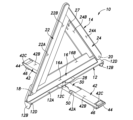
1対の第2脚部材42の互いの離間距離(スパン)は、使用位置において、基端部43より接地部42Cに向かうに従って長くなり、接地部42Cにおいて最大値Lになる。この構成により、第1ベース部材12と第2ベース部材30との長手方向の長さが同じであっても、1対の第2脚部材42の接地部42Cの互いの離間距離の最大値Lは第1ベース部材12及び第2ベース部材30の長手方向の長さより長くなる。
In the use position, the distance (span) between the pair of second leg members 42 increases from the base end 43 toward the grounding section 42C, and reaches the maximum value L at the grounding section 42C. With this configuration, even if the lengths in the longitudinal direction of the first base member 12 and the second base member 30 are the same, the maximum value L of the mutual separation distance of the ground contact portions 42C of the pair of second leg members 42 is longer than the length of the first base member 12 and the second base member 30 in the longitudinal direction.
これにより、停止表示器10は、図1及び図2に示されているような使用状態において、1対の第2脚部材42がない場合に比して路上に倒れ難く安定して設置されると共に、風によって倒され難くい耐風性が高くなる。
As a result, the stop indicator 10 is installed more stably on the road than in the case where the pair of second leg members 42 is not provided in the usage state shown in FIGS. 1 and 2. At the same time, it has high wind resistance, making it difficult to be knocked over by the wind.
停止表示器10は、使用状態にある三角表示部14が正面を向く前後方向に風を受け易い。このことに対して、停止表示器10は、使用状態において前後に位置する1対の第2脚部材42によって接地部42Cの前後方向の離間距離が拡張されていることにより、耐風性が効果的に向上する。また、接地部42Cに第1接地シート44が貼着されていることにより、使用状態での停止表示器10の路上設置の安定性が向上する。
The stop indicator 10 is easily exposed to wind in the front-rear direction where the triangular display section 14 faces forward when in use. In contrast, the stop indicator 10 has effective wind resistance because the distance in the front and back direction of the ground contact portion 42C is expanded by the pair of second leg members 42 located in the front and rear in the state of use. improve. Furthermore, since the first grounding sheet 44 is attached to the grounding portion 42C, the stability of installing the stop indicator 10 on the road during use is improved.
また、各第2脚部材42の接地部42Cは、主部42Bに対して折曲可能に可撓性を有して接続されているから、路面の傾斜等に倣って主部42Bに対して任意の角度を持つことができる。このことによっても、使用状態での停止表示器10の路上設置の安定性が向上する。接地部42Cは、格納位置では主部42Bと同方向に延在するように主部42Bに対して折曲することにより、格納性も良好なものになる。
In addition, since the grounding portion 42C of each second leg member 42 is connected to the main portion 42B with bendability and flexibility, the grounding portion 42C of each second leg member 42 is connected to the main portion 42B by following the slope of the road surface, etc. Can have any angle. This also improves the stability of installing the stop indicator 10 on the road during use. By bending the grounding portion 42C with respect to the main portion 42B so as to extend in the same direction as the main portion 42B in the storage position, storage performance is also improved.
停止表示器10は、1対の第2脚部材42を折り畳んだ格納状態でも、路上に設置して使用することもできる。この使用状態は、各第2脚部材42は第2接地シート46をもって路上に接地する。これにより、当該使用状態でも停止表示器10の路上設置の安定性が向上する。
The stop indicator 10 can be used in a stored state with the pair of second leg members 42 folded or installed on the road. In this state of use, each second leg member 42 touches the road with the second grounding sheet 46. This improves the stability of installing the stop indicator 10 on the road even in this usage state.
1対の第2脚部材42を折り畳んだ格納状態での停止表示器10は、平らな路面上等での使用に適しており、停止表示器10の路上設置の安定性がよい。これに対し、図1~図3に示されているように、一対の第2脚部材42が拡張された状態の停止表示器10の使用は不整地等の使用に適している。
The stop indicator 10 in the retracted state with the pair of second leg members 42 folded is suitable for use on a flat road surface, etc., and the stop indicator 10 can be installed stably on the road. On the other hand, as shown in FIGS. 1 to 3, the use of the stop indicator 10 with the pair of second leg members 42 expanded is suitable for use on rough terrain.
1対の第1脚部材34及び1対の第2脚部材42は、上下に互いに重なり合うようにして、しかも第2ベース部材30に上下に重なり合うように折り畳まれるから、停止表示器10は、第1脚部材34及び第2脚部材42が設けられても、不使用時のコンパクト性が阻害されることがない。
Since the pair of first leg members 34 and the pair of second leg members 42 are vertically overlapped with each other and folded into the second base member 30 so as to be vertically overlapped, the stop indicator 10 Even if the one leg member 34 and the second leg member 42 are provided, the compactness when not in use is not hindered.
(実施形態2)
実施形態2による停止表示器10を、図7~図10を参照して説明する。なお、図7~図10において、図1~図6に対応する部分は、図1~図6に付した符号と同一の符号を付けて、その説明を省略する。尚、停止表示器を構成する各部材は樹脂成形品であってよい。 (Embodiment 2)
Astop indicator 10 according to a second embodiment will be described with reference to FIGS. 7 to 10. Note that in FIGS. 7 to 10, parts corresponding to FIGS. 1 to 6 are designated by the same reference numerals as those in FIGS. 1 to 6, and the description thereof will be omitted. Note that each member constituting the stop indicator may be a resin molded product.
実施形態2による停止表示器10を、図7~図10を参照して説明する。なお、図7~図10において、図1~図6に対応する部分は、図1~図6に付した符号と同一の符号を付けて、その説明を省略する。尚、停止表示器を構成する各部材は樹脂成形品であってよい。 (Embodiment 2)
A
実施形態2では、第2ベース部材30は中央部30Aを挟んだ両側(図7で見て前側及び後側)の両側面(図7で見て左側面及び右側面)の各々に開口した案内凹部48を有する。各第2脚部材42の基端部42Aは、第2ベース部材30の両側面の対向する内側面を備えた片部を含み、各片部に、対応する案内凹部48に係合する摺動突部50を有する。
In the second embodiment, the second base member 30 has guides that are open on both sides (the left side and the right side as seen in FIG. 7) on both sides (the front side and the rear side as seen in FIG. 7) across the center portion 30A. It has a recess 48 . The proximal end 42A of each second leg member 42 includes a piece with opposing inner surfaces on both sides of the second base member 30, and each piece has a sliding portion that engages a corresponding guide recess 48. It has a protrusion 50.
案内凹部48及び摺動突部50の詳細を、図9を参照して説明する。
Details of the guide recess 48 and sliding protrusion 50 will be explained with reference to FIG. 9.
案内凹部48は、第2ベース部材30の延在方向に延在し、案内凹部48の大部分をなす直線案内部48Aと、直線案内部48Aの第2ベース部材30の端部30B側の終端に形成され、下方への拡張部を含む回動傾斜案内部48Bと、端部30B側の終端から斜め下方へ向けて拡張された部分を含む回動傾斜案内部48Bと、端部30B側の終端近傍から斜め上方へ向けて拡張された部分を含む係止凹部48Cとを互いに連続して有する。
The guide recess 48 extends in the extending direction of the second base member 30, and includes a linear guide portion 48A forming the majority of the guide recess 48, and a terminal end of the linear guide portion 48A on the end 30B side of the second base member 30. A rotating inclined guide portion 48B including a downwardly expanding portion, a rotating inclined guiding portion 48B including a portion extending diagonally downward from the terminal end on the end 30B side, A locking recess 48C including a portion extending obliquely upward from the vicinity of the terminal end is continuous to the locking recess 48C.
摺動突部50は、直線案内部48Aの延在方向に摺動可能に係合して第2ベース部材30に対する第2脚部材42の長手方向の移動を案内する略矩形の摺動案内部分50Aと、係止凹部48Cに進入可能な係止突出部50Bとを一体に有する。
The sliding protrusion 50 is a substantially rectangular sliding guide portion that is slidably engaged in the extending direction of the linear guide portion 48A and guides the movement of the second leg member 42 in the longitudinal direction with respect to the second base member 30. 50A and a locking protrusion 50B that can enter into the locking recess 48C.
摺動突部50は、図9(A)に示されているように、摺動案内部分50Aが直線案内部48Aの長手方向に摺動してその終端側に移動し、図9(B)に示されているように、直線案内部48Aの終端における第2脚部材42の第2ベース部材30に対する斜め下方への回動によって回動傾斜案内部48Bに落ち込み、図9(C)に示されているように、第2脚部材42の第2ベース部材30に対する斜め上方の移動により、係止突出部50Bが係止凹部48Cに進入する。係止突出部50Bが係止凹部48Cに進入することにより、第2脚部材42が第2ベース部材30に対して斜め下方に延出した使用位置に係止される。
In the sliding protrusion 50, as shown in FIG. 9(A), the sliding guide portion 50A slides in the longitudinal direction of the linear guide portion 48A and moves to the terminal end thereof, and as shown in FIG. 9(B). As shown in FIG. 9(C), the second leg member 42 at the end of the linear guide portion 48A rotates diagonally downward with respect to the second base member 30, and falls into the rotating inclined guide portion 48B, as shown in FIG. 9(C). As shown in FIG. 3, the oblique upward movement of the second leg member 42 with respect to the second base member 30 causes the locking protrusion 50B to enter the locking recess 48C. By entering the locking protrusion 50B into the locking recess 48C, the second leg member 42 is locked in the use position extending obliquely downward relative to the second base member 30.
図10(A)~(C)を参照して、格納位置にある第2脚部材42を使用者によって使用位置に移動させる動作について説明する。
With reference to FIGS. 10(A) to 10(C), the operation of moving the second leg member 42 from the storage position to the use position by the user will be described.
図10(A)に示されているように、各第2脚部材42が第2ベース部材30の上側に重なり合った格納位置にある状態から、各第2脚部材42を第2ベース部材30の延在方向に沿って第2ベース部材30の端部30B側に摺動させ、図10(B)に示されているように、各第2脚部材42を第2ベース部材30の端部側に引き出す。
As shown in FIG. 10(A), from the stored position where each second leg member 42 overlaps the upper side of the second base member 30, each second leg member 42 is moved to the second base member 30. Each second leg member 42 is slid toward the end 30B side of the second base member 30 along the extending direction, and as shown in FIG. Pull it out.
引き出しが完了した時点で、図10(C)に示されているよう第2ベース部材30に、各第2脚部材42を第2ベース部材30に対して下側に回動変位させ、その後、斜め上方に移動させる。これにより、各第2脚部材42は、図10(C)に示されている係止状態のもとに使用位置に固定される。実施形態2においても、1対の第2脚部材42の接地部42Cの互いの離間距離の最大値Lは第2ベース部材30の長手方向の長さより長くなる。
When the withdrawal is completed, the second base member 30 is rotated to displace each second leg member 42 downward with respect to the second base member 30, as shown in FIG. 10(C), and then, Move diagonally upward. Thereby, each second leg member 42 is fixed in the use position in the locked state shown in FIG. 10(C). Also in the second embodiment, the maximum value L of the distance between the ground contact portions 42C of the pair of second leg members 42 is longer than the length of the second base member 30 in the longitudinal direction.
これにより、実施形態2の停止表示器10も、実施形態1の停止表示器10と同様に、1対の第2脚部材42がない場合に比して路上に倒れ難く安定して設置されると共に、風によって倒され難くい耐風性が高くなる。1対の第2脚部材42は、第2ベース部材30に上下に重なり合うようにして格納されるから、実施形態2の停止表示器10も、第2脚部材42が設けられても、不使用時のコンパクト性が阻害されることがない。
As a result, the stop indicator 10 of the second embodiment, similarly to the stop indicator 10 of the first embodiment, is less likely to fall down on the road and is stably installed compared to the case where the pair of second leg members 42 is not provided. At the same time, it has high wind resistance, making it difficult to be knocked over by the wind. Since the pair of second leg members 42 are stored in the second base member 30 so as to overlap vertically, the stop indicator 10 of the second embodiment also does not need to be used even if the second leg members 42 are provided. The compactness of the time is not hindered.
実施形態2では、第2接地シート46は、第2ベース部材30の各端部の下面に貼着されている。各第2脚部材42が格納された状態での停止表示器10の使用においては、各第2接地シート46が路上に接地することになる。
In the second embodiment, the second grounding sheet 46 is attached to the lower surface of each end of the second base member 30. When the stop indicator 10 is used with each second leg member 42 retracted, each second grounding sheet 46 comes into contact with the road.
(実施形態3)
実施形態3による停止表示器10を、図11を参照して説明する。なお、図11において、図7に対応する部分は、図7に付した符号と同一の符号を付けて、その説明を省略する。尚、停止表示器を構成する各部材は樹脂成形品であってよい。 (Embodiment 3)
Astop indicator 10 according to a third embodiment will be described with reference to FIG. 11. In FIG. 11, parts corresponding to those in FIG. 7 are denoted by the same reference numerals as those in FIG. 7, and the explanation thereof will be omitted. Note that each member constituting the stop indicator may be a resin molded product.
実施形態3による停止表示器10を、図11を参照して説明する。なお、図11において、図7に対応する部分は、図7に付した符号と同一の符号を付けて、その説明を省略する。尚、停止表示器を構成する各部材は樹脂成形品であってよい。 (Embodiment 3)
A
実施形態3では、各第2脚部材42の接地部(遊端)42Cに長方体形状の接地部材52が折り畳み式に収納可能に取り付けられている。接地部材52の左右側面には各々案内凹部54が形成されている。接地部42Cには案内凹部54に係合する摺動突部56が形成されている。
In the third embodiment, a rectangular parallelepiped-shaped grounding member 52 is attached to the grounding portion (free end) 42C of each second leg member 42 so as to be foldable and storable. Guide recesses 54 are formed on the left and right side surfaces of the grounding member 52, respectively. A sliding protrusion 56 that engages with the guide recess 54 is formed on the grounding portion 42C.
案内凹部54及び摺動突部56は実施形態2の案内凹部48及び摺動突部50と実質的に同じ形状及び構造になっている。これにより、各第2脚部材42は、図11に示されているように、第2ベース部材30と平行で、第2脚部材42の接地部42Cから前後方向の外方に向けて延出した使用位置と、第2脚部材42の長手方向に沿う方向に移動した格納位置との間を移動可能である。
The guide recess 54 and the sliding protrusion 56 have substantially the same shape and structure as the guide recess 48 and the sliding protrusion 50 of the second embodiment. Thereby, each second leg member 42 is parallel to the second base member 30 and extends outward in the front-rear direction from the ground contact portion 42C of the second leg member 42, as shown in FIG. The second leg member 42 is movable between a used position and a stored position moved in the longitudinal direction of the second leg member 42.
これにより、停止表示器10の前後の接地点の最大スパンが使用位置にある前後の接地部材52によって更に拡大され、停止表示器10が、より一層、前後に倒れ難くなる。
As a result, the maximum span of the front and rear grounding points of the stop indicator 10 is further expanded by the front and rear grounding members 52 in the use position, and the stop indicator 10 becomes even more difficult to fall back and forth.
尚、各接地部材52の底面には第1接地シート44が貼着されていてよい。
Note that the first grounding sheet 44 may be attached to the bottom surface of each grounding member 52.
以上で具体的な実施形態の説明を終えるが、本発明は上記実施形態や変形例に限定されることなく、幅広く変形実施することができる。例えば、実施形態1の第2脚部材42のストッパ構造は、図3の部分拡大図に示されている構造のものに限られることはなく、例えば、ストッパピン等を用いた構造のものであってもよい。三角表示部14の構造は、実施形態のものに限られることはなく、従来、知られている種々の構造を用いることができる。
Although the description of the specific embodiments has been completed above, the present invention is not limited to the above-described embodiments and modifications, and can be implemented in a wide range of modifications. For example, the stopper structure of the second leg member 42 of the first embodiment is not limited to the structure shown in the partially enlarged view of FIG. 3, and may be, for example, a structure using a stopper pin or the like. It's okay. The structure of the triangular display section 14 is not limited to that of the embodiment, and various conventionally known structures can be used.
10 :停止表示器
12 :第1ベース部材
12A :主部
12B :短片部
12D :端部
14 :三角表示部
16 :底辺部材
16A :光反射部
16B :蛍光部
18 :軸部
20 :軸部
22 :斜辺部材
22A :反射部
22B :蛍光部
22C :拡張板状部
23 :基端
24 :斜辺部材
24A :反射部
24B :蛍光部
25 :基端
26 :斜辺部材
27 :係止片部
28 :軸部
30 :第2ベース部材
30A :中央部
30B :端部
31 :軸受孔
32 :軸部
33 :拡張溝
33A :壁部
34 :第1脚部材
34A :基端部
34B :接地部
36 :係合孔
38 :突部
40 :軸部
40A :係止用突起
42 :第2脚部材
42A :基端部
42B :主部
42C :接地部
43 :基端部
43A :底壁
43B :側壁
44 :第1接地シート
46 :第2接地シート
48 :案内凹部
48A :直線案内部
48B :回動傾斜案内部
48C :係止凹部
50 :摺動突部
50A :摺動案内部分
50B :係止突出部
52 :接地部材
54 :案内凹部
56 :摺動突部 10 : Stop indicator 12 :First base member 12A : Main part 12B : Short piece part 12D : End part 14 : Triangular display part 16 : Bottom member 16A : Light reflecting part 16B : Fluorescent part 18 : Shaft part 20 : Shaft part 22 : Hypotenuse member 22A : Reflective part 22B : Fluorescent part 22C : Expanded plate-like part 23 : Base end 24 : Hypotenuse member 24A : Reflective part 24B : Fluorescent part 25 : Base end 26 : Hytentenuse member 27 : Locking piece part 28 : Shaft Part 30 : Second base member 30A : Central part 30B : End part 31 : Bearing hole 32 : Shaft part 33 : Expansion groove 33A : Wall part 34 : First leg member 34A : Base end part 34B : Grounding part 36 : Engagement Hole 38: Protrusion 40: Shaft 40A: Locking protrusion 42: Second leg member 42A: Base end 42B: Main part 42C: Grounding part 43: Base end 43A: Bottom wall 43B: Side wall 44: First Grounding sheet 46 : Second grounding sheet 48 : Guide recess 48A : Linear guide part 48B : Rotating inclined guide part 48C : Locking recess 50 : Sliding protrusion 50A : Sliding guide part 50B : Locking protrusion 52 : Grounding Member 54: Guide recess 56: Sliding protrusion
12 :第1ベース部材
12A :主部
12B :短片部
12D :端部
14 :三角表示部
16 :底辺部材
16A :光反射部
16B :蛍光部
18 :軸部
20 :軸部
22 :斜辺部材
22A :反射部
22B :蛍光部
22C :拡張板状部
23 :基端
24 :斜辺部材
24A :反射部
24B :蛍光部
25 :基端
26 :斜辺部材
27 :係止片部
28 :軸部
30 :第2ベース部材
30A :中央部
30B :端部
31 :軸受孔
32 :軸部
33 :拡張溝
33A :壁部
34 :第1脚部材
34A :基端部
34B :接地部
36 :係合孔
38 :突部
40 :軸部
40A :係止用突起
42 :第2脚部材
42A :基端部
42B :主部
42C :接地部
43 :基端部
43A :底壁
43B :側壁
44 :第1接地シート
46 :第2接地シート
48 :案内凹部
48A :直線案内部
48B :回動傾斜案内部
48C :係止凹部
50 :摺動突部
50A :摺動案内部分
50B :係止突出部
52 :接地部材
54 :案内凹部
56 :摺動突部 10 : Stop indicator 12 :
Claims (8)
- 三角形状をなす停止表示器であって、
水平方向に延在する直線状をなす第1ベース部材と、
前記第1ベース部材の上面に立設された三角表示部と、
水平方向に延在する直線状をなし、前記第1ベース部材の延在方向と同方向に延在する格納位置と前記第1ベース部材の延在方向に直交する方向に延在する使用位置との間を回動可能に、前記第1ベース部材の中央部に鉛直な軸線周りに回動可能に連結された中央部を含む第2ベース部材と、
前記第1ベース部材と重なり合う格納位置と、前記第1ベース部材より垂下する使用位置との間を回動可能であるように、前記第1ベース部材の両端部に、前記第1ベース部材に直交する水平な軸線周りに回動可能に連結された基端部を含む1対の第1脚部材と、
前記第2ベース部材と重なり合う格納位置と前記第2ベース部材の端部から外方に張り出した使用位置との間を回動可能であるように、前記第2ベース部材の両端部に、前記第2ベース部材に直交する水平な軸線周りに回動可能に連結された基端部を含む1対の第2脚部材とを有する停止表示器。 A stop indicator having a triangular shape,
a first base member having a linear shape extending in the horizontal direction;
a triangular display section erected on the upper surface of the first base member;
A storage position that has a linear shape extending in the horizontal direction and extends in the same direction as the extending direction of the first base member, and a use position that extends in a direction perpendicular to the extending direction of the first base member. a second base member including a central portion rotatably connected to the central portion of the first base member so as to be rotatable around a vertical axis;
At both ends of the first base member, perpendicular to the first base member, so as to be rotatable between a storage position overlapping the first base member and a use position hanging down from the first base member. a pair of first leg members including proximal ends rotatably connected around a horizontal axis;
The second base member is provided at both ends of the second base member so as to be rotatable between a storage position overlapping the second base member and a use position projecting outward from the end of the second base member. and a pair of second leg members including a base end rotatably connected around a horizontal axis perpendicular to the second base member. - 各第2脚部材は、前記基端部を含む直線状の主部と、前記主部の遊端部の側に前記主部に対して折曲可能に可撓性を有して接続された接地部とを有する請求項1に記載の停止表示器。 Each of the second leg members is connected to a straight main part including the base end part and to a free end part side of the main part so as to be bendable with respect to the main part. The stop indicator according to claim 1, further comprising a grounding portion.
- 各接地部にエラストマ材による第1接地シートが設けられている請求項1又は2に記載の停止表示器。 The stop indicator according to claim 1 or 2, wherein each grounding portion is provided with a first grounding sheet made of an elastomer material.
- 前記格納位置において下向きになる各第2脚部材の表面に、エラストマ材による第2接地シートが設けられている請求項1又は2に記載の停止表示器。 The stop indicator according to claim 1 or 2, wherein a second grounding sheet made of an elastomer material is provided on the surface of each second leg member that faces downward in the storage position.
- 前記第2ベース部材は横断面形状が矩形の棒状部材により構成され、
各第2脚部材は、収納位置に於いて、前記第2ベース部材を受容する溝形断面形状を有する請求項1又は2に記載の停止表示器。 The second base member is constituted by a rod-shaped member having a rectangular cross-sectional shape,
3. A stop indicator according to claim 1, wherein each second leg member has a channel-shaped cross-sectional shape to receive the second base member in the stowed position. - 前記第2ベース部材は自身の延在方向に長い長孔を有し、
前記第2脚部材は前記長孔に回動且つ摺動可能に係合する軸部を有し、前記第2ベース部材の延在方向に対する摺動により前記第2ベース部材と重なり合う請求項1又は2に記載の停止表示器。 The second base member has a long hole extending in the direction in which the second base member extends,
2. The second leg member has a shaft portion that rotatably and slidably engages with the elongated hole, and overlaps the second base member by sliding in the extending direction of the second base member. 2. The stop indicator according to 2. - 各第1脚部材及び各第2脚部材は、それぞれの格納位置にある時に、上下に重なり合うよう格納される請求項1又は2に記載の停止表示器。 The stop indicator according to claim 1 or 2, wherein each first leg member and each second leg member are stored so as to be vertically overlapped when in their respective storage positions.
- 前記第1ベース部材に固定され、前記三角表示部の底辺をなす底辺部材と、
前記底辺部材に重なり合う位置する格納位置と前記三角表示部の両斜辺を形成する展開位置との間で回動可能に、前記底辺部材の両端に、前記第1ベース部材に直交する水平な軸線周りに回動可能に連結された基端を含む1対の斜辺部材とを有する請求項1又は2に記載の停止表示器。 a bottom member fixed to the first base member and forming the bottom of the triangular display section;
Rotatable between a storage position overlapping the bottom member and a deployed position forming both oblique sides of the triangular display section, the bottom member is provided at both ends thereof around a horizontal axis perpendicular to the first base member. 3. The stop indicator according to claim 1, further comprising: a pair of hypotenuse members including a base end rotatably connected to the stop indicator.
Applications Claiming Priority (2)
| Application Number | Priority Date | Filing Date | Title |
|---|---|---|---|
| JP2022-067604 | 2022-04-15 | ||
| JP2022067604 | 2022-04-15 |
Publications (1)
| Publication Number | Publication Date |
|---|---|
| WO2023199968A1 true WO2023199968A1 (en) | 2023-10-19 |
Family
ID=88329896
Family Applications (1)
| Application Number | Title | Priority Date | Filing Date |
|---|---|---|---|
| PCT/JP2023/014976 WO2023199968A1 (en) | 2022-04-15 | 2023-04-13 | Stop indicator |
Country Status (1)
| Country | Link |
|---|---|
| WO (1) | WO2023199968A1 (en) |
Citations (5)
| Publication number | Priority date | Publication date | Assignee | Title |
|---|---|---|---|---|
| JPS4872878U (en) * | 1971-12-15 | 1973-09-11 | ||
| JPS50129091U (en) * | 1974-04-05 | 1975-10-23 | ||
| JP2002072935A (en) * | 2000-09-05 | 2002-03-12 | Ryoei Plastic:Kk | Stop display plate for automobile |
| EP2067661A2 (en) * | 2007-12-06 | 2009-06-10 | AUTOTEK S.r.l. | Emergency stop warning device for motor vehicles in general, particularly warning triangle |
| JP6257699B2 (en) * | 2016-05-30 | 2018-01-10 | エーモン工業株式会社 | Triangular stop display board |
-
2023
- 2023-04-13 WO PCT/JP2023/014976 patent/WO2023199968A1/en unknown
Patent Citations (5)
| Publication number | Priority date | Publication date | Assignee | Title |
|---|---|---|---|---|
| JPS4872878U (en) * | 1971-12-15 | 1973-09-11 | ||
| JPS50129091U (en) * | 1974-04-05 | 1975-10-23 | ||
| JP2002072935A (en) * | 2000-09-05 | 2002-03-12 | Ryoei Plastic:Kk | Stop display plate for automobile |
| EP2067661A2 (en) * | 2007-12-06 | 2009-06-10 | AUTOTEK S.r.l. | Emergency stop warning device for motor vehicles in general, particularly warning triangle |
| JP6257699B2 (en) * | 2016-05-30 | 2018-01-10 | エーモン工業株式会社 | Triangular stop display board |
Similar Documents
| Publication | Publication Date | Title |
|---|---|---|
| KR101127699B1 (en) | Flexible Display Apparatus for Mobile Terminals | |
| US7902457B2 (en) | Adjustable mounting bracket | |
| CN104464529A (en) | Flexible display device having guide member | |
| CN110599907A (en) | Foldable display device | |
| CN107054623B (en) | Unmanned aerial vehicle slidingtype horn device and unmanned aerial vehicle | |
| JPH11142974A (en) | Portable type screen | |
| KR910700158A (en) | Chassis Frame for Motor Vehicle | |
| WO2023199968A1 (en) | Stop indicator | |
| US6568734B2 (en) | Straight motion parallelogram linkage | |
| CN105346464B (en) | Storage assembly with deployable compartment | |
| US20200245734A1 (en) | Suitcase | |
| US8348360B2 (en) | Elementary support for object display comprising a hinge polyhedral compartment | |
| JP2019098845A (en) | Vehicle rear structure | |
| JP6109256B2 (en) | Body widening structure for widened vehicles | |
| JP2010024653A (en) | Lock mechanism of extensible/contractible object | |
| JP2018144775A (en) | Slope and vehicle slope device | |
| JP5723513B2 (en) | Slope device for vehicle | |
| CN110738929A (en) | multi-screen splicing and routing method and device and electronic equipment | |
| JP4261499B2 (en) | Vehicle table structure | |
| KR101231354B1 (en) | variable type luggage board | |
| KR102089649B1 (en) | Multi-directional expandable workbench | |
| US11759025B2 (en) | Outer layer engagement clip | |
| CN112356751A (en) | Table for vehicle and vehicle | |
| JP4878780B2 (en) | Wire harness holding structure | |
| CN207482025U (en) | Reinforcement structure, centre gangway structure and automobile |
Legal Events
| Date | Code | Title | Description |
|---|---|---|---|
| 121 | Ep: the epo has been informed by wipo that ep was designated in this application |
Ref document number: 23788386 Country of ref document: EP Kind code of ref document: A1 |