WO2023199800A1 - 冷凍サイクル装置 - Google Patents
冷凍サイクル装置 Download PDFInfo
- Publication number
- WO2023199800A1 WO2023199800A1 PCT/JP2023/013969 JP2023013969W WO2023199800A1 WO 2023199800 A1 WO2023199800 A1 WO 2023199800A1 JP 2023013969 W JP2023013969 W JP 2023013969W WO 2023199800 A1 WO2023199800 A1 WO 2023199800A1
- Authority
- WO
- WIPO (PCT)
- Prior art keywords
- refrigerant
- pressure
- compressor
- valve
- temperature
- Prior art date
- Legal status (The legal status is an assumption and is not a legal conclusion. Google has not performed a legal analysis and makes no representation as to the accuracy of the status listed.)
- Ceased
Links
Images





Classifications
-
- F—MECHANICAL ENGINEERING; LIGHTING; HEATING; WEAPONS; BLASTING
- F25—REFRIGERATION OR COOLING; COMBINED HEATING AND REFRIGERATION SYSTEMS; HEAT PUMP SYSTEMS; MANUFACTURE OR STORAGE OF ICE; LIQUEFACTION SOLIDIFICATION OF GASES
- F25B—REFRIGERATION MACHINES, PLANTS OR SYSTEMS; COMBINED HEATING AND REFRIGERATION SYSTEMS; HEAT PUMP SYSTEMS
- F25B1/00—Compression machines, plants or systems with non-reversible cycle
-
- F—MECHANICAL ENGINEERING; LIGHTING; HEATING; WEAPONS; BLASTING
- F25—REFRIGERATION OR COOLING; COMBINED HEATING AND REFRIGERATION SYSTEMS; HEAT PUMP SYSTEMS; MANUFACTURE OR STORAGE OF ICE; LIQUEFACTION SOLIDIFICATION OF GASES
- F25B—REFRIGERATION MACHINES, PLANTS OR SYSTEMS; COMBINED HEATING AND REFRIGERATION SYSTEMS; HEAT PUMP SYSTEMS
- F25B1/00—Compression machines, plants or systems with non-reversible cycle
- F25B1/10—Compression machines, plants or systems with non-reversible cycle with multi-stage compression
-
- F—MECHANICAL ENGINEERING; LIGHTING; HEATING; WEAPONS; BLASTING
- F25—REFRIGERATION OR COOLING; COMBINED HEATING AND REFRIGERATION SYSTEMS; HEAT PUMP SYSTEMS; MANUFACTURE OR STORAGE OF ICE; LIQUEFACTION SOLIDIFICATION OF GASES
- F25B—REFRIGERATION MACHINES, PLANTS OR SYSTEMS; COMBINED HEATING AND REFRIGERATION SYSTEMS; HEAT PUMP SYSTEMS
- F25B7/00—Compression machines, plants or systems, with cascade operation, i.e. with two or more circuits, the heat from the condenser of one circuit being absorbed by the evaporator of the next circuit
Definitions
- the present disclosure relates to a refrigeration cycle device that uses carbon dioxide as a refrigerant.
- a refrigeration cycle device that uses carbon dioxide (R744) as a refrigerant
- the pressure of the refrigerant is, for example, 10 [MPa], which is higher than in the case where the refrigerant is, for example, chlorofluorocarbon. Therefore, components such as heat exchangers, containers, and refrigerant piping in refrigeration cycle devices that use R744 as a refrigerant are required to have high pressure resistance.
- such a refrigeration cycle device may be provided with various components for preventing the pressure of the refrigerant from exceeding the design pressure in the installation environment (see, for example, Patent Document 1).
- Such components include a safety valve for releasing refrigerant to the outside when the pressure of refrigerant in the refrigerant circuit becomes high.
- the present disclosure has been made to solve the above problems, and by reducing the pressure of the refrigerant before the safety valve operates, damage to the refrigeration cycle device can be suppressed, operation can be restarted quickly, and safety can be improved.
- the object of the present invention is to provide a refrigeration cycle device that improves
- a refrigeration cycle device is a refrigeration cycle device that circulates a first refrigerant that is carbon dioxide through a first refrigerant circuit to cool a first object with the first refrigerant, and compresses the first refrigerant.
- a first compressor that cools the first refrigerant by exchanging heat with the first refrigerant discharged from the first compressor; an evaporator that exchanges heat with a target; and an evaporator that is provided upstream of the evaporator in the first refrigerant circuit, reduces the pressure of the first refrigerant in an open state, and distributes the reduced pressure of the first refrigerant to the evaporator.
- a first pressure detection device that detects a first pressure that is the pressure of the first refrigerant between the downstream side of the first compressor and the first valve; a first temperature detection device that detects a first temperature that is the temperature of a second object; a control device that controls the first compressor and the first valve; and a second refrigerant circuit that circulates a second refrigerant.
- the second target is the second refrigerant
- the second refrigerant circuit includes a second compressor that compresses the second refrigerant, and a third refrigerant that compresses the second refrigerant discharged from the second compressor.
- a second heat exchanger that exchanges heat with the target and condenses the second refrigerant; a second valve that reduces the pressure of the second refrigerant condensed in the second heat exchanger; and the first heat exchanger. and the first heat exchanger exchanges heat between the second refrigerant whose pressure has been reduced by the second valve and the first refrigerant discharged from the first compressor, and condenses the first refrigerant. and evaporates the second refrigerant, when the first pressure is equal to or higher than a predetermined first threshold pressure and the first temperature is equal to or lower than a predetermined threshold temperature.
- the first valve is controlled to be in an open state.
- the control device when the first pressure is equal to or higher than the first threshold pressure and the temperature of the first object is equal to or lower than the threshold temperature, the control device opens the first valve. and causing the first refrigerant to flow through the evaporator. This reduces the first pressure of the first refrigerant in the first refrigerant circuit, such as the receiver. Therefore, operation of the safety valve and damage to the refrigeration cycle device are suppressed.
- the refrigeration cycle device can quickly resume operation after normal refrigerant distribution is restored. Further, by suppressing the operation of the safety valve, the release of the first refrigerant into the atmosphere is suppressed, so that workers, users, etc. are suppressed from being exposed to the first refrigerant. Therefore, safety is improved.
- FIG. 1 is a schematic diagram showing a configuration example of a refrigeration cycle device according to Embodiment 1.
- FIG. 1 is a block diagram illustrating a hardware configuration of a control device in Embodiment 1.
- FIG. 2 is a flowchart illustrating the flow of pressure adjustment processing by the refrigeration cycle device according to the first embodiment.
- FIG. 2 is a schematic diagram showing a configuration example of a refrigeration cycle device according to a second embodiment.
- 7 is a flowchart illustrating the flow of pressure adjustment processing by the refrigeration cycle device according to Embodiment 2.
- FIG. FIG. 7 is a schematic diagram showing a configuration example of a user-side device in Embodiment 3.
- FIG. FIG. 7 is a schematic diagram showing a configuration example of a user-side device in Embodiment 4.
- 12 is a flowchart illustrating the flow of pressure adjustment processing by the refrigeration cycle device according to the fifth embodiment. It is a schematic diagram showing the example of composition of the refrigeration cycle device concerning Embodiment 6.
- 12 is a flowchart illustrating the flow of pressure adjustment processing by the refrigeration cycle device according to Embodiment 6.
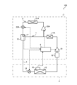
- FIG. 1 is a schematic diagram showing a configuration example of a refrigeration cycle device 100 according to the first embodiment.
- the refrigeration cycle device 100 is a system that uses a first refrigerant to cool a first object, such as air or water, to a temperature desired by a user.
- the first refrigerant is carbon dioxide (R744) refrigerant.
- the refrigeration cycle device 100 includes a first refrigerant circuit 1 in which a first refrigerant circulates, and a second refrigerant circuit 2 in which a second refrigerant circulates.
- the second refrigerant may be an HFC refrigerant with high flowability, such as R32, R410A, or R448A, or may be a natural refrigerant, such as R290 or R717, which has fewer environmental problems. Note that the refrigeration cycle device 100 may not include the second refrigerant circuit 2.
- the refrigeration cycle device 100 includes a heat source device 3 and a user device 4.
- the heat source device 3 and the user device 4 are connected to each other by a first refrigerant pipe 5.
- the refrigeration cycle device 100 includes a control device 6 .
- a rectangle indicated by a dashed dotted line indicates a casing forming the outer shell of the heat source device 3, and an example is shown in which a control device 6 is installed inside the casing, but the control device 6 is installed outside the casing. may be installed.
- a part of the control device 6 may be provided in the heat source device 3 and the remaining portion may be provided in the user device 4. In this case, a portion of the control device 6 in the heat source device 3 and the user device 4 may operate in cooperation with the remaining parts of the control device 6.
- the first refrigerant circuit 1 includes a first compressor 10, a primary heat exchanger 11, a refrigerant heat exchanger 12, a receiver 13, a first pressure reducing valve 14, and an evaporator, which are sequentially connected by a first refrigerant pipe 5. It has a container 15 and a gas-liquid separator 16.
- the first compressor 10 , the primary heat exchanger 11 , the refrigerant heat exchanger 12 , the liquid receiver 13 , and the gas-liquid separator 16 are arranged within the housing of the heat source device 3 .
- the first pressure reducing valve 14 and the evaporator 15 are arranged inside a casing forming the outer shell of the user-side device 4, which is indicated by a square with two-dot chain lines in FIG.
- the first pressure reducing valve 14 may be provided outside the housing of the user device 4.
- the second refrigerant circuit 2 includes a secondary compressor 20, a secondary condenser 21, a secondary pressure reducing valve 22, and an inter-refrigerant heat exchanger 12, which are sequentially connected by a second refrigerant pipe 7.
- the second refrigerant circuit 2 is arranged within the housing of the heat source device 3.
- the first compressor 10 is a scroll type, rotary type, reciprocating type, or screw type compressor, and is an inverter compressor whose capacity can be controlled by an inverter.
- the first compressor 10 sucks the first refrigerant from the first refrigerant pipe 5 and compresses the sucked first refrigerant.
- the first compressor 10 then discharges the compressed first refrigerant to the first refrigerant pipe 5.
- the primary heat exchanger 11 may be air-cooled or water-cooled.
- Examples of the air-cooled primary heat exchanger 11 include a plate-fin-tube heat exchanger, a parallel flow condenser, and the like.
- Examples of the water-cooled primary heat exchanger 11 include a shell and tube heat exchanger, a plate heat exchanger, a double pipe heat exchanger, and the like.
- the primary heat exchanger 11 cools the first refrigerant by exchanging heat between the first refrigerant and air or water.
- the refrigeration cycle device 100 may not include the primary heat exchanger 11. However, in order to reduce thermal stress on the refrigerant heat exchanger 12 due to the first refrigerant discharged from the first compressor 10, it is desirable that the refrigeration cycle device 100 includes the primary heat exchanger 11.
- the inter-refrigerant heat exchanger 12 is provided downstream of the primary heat exchanger 11.
- the refrigerant heat exchanger 12 is, for example, a plate heat exchanger, and exchanges heat between the first refrigerant and the second refrigerant.
- the refrigerant heat exchanger 12 functions as a condenser in the first refrigerant circuit 1 and as an evaporator in the second refrigerant circuit 2.
- the first refrigerant radiates heat to the second refrigerant in the inter-refrigerant heat exchanger 12 and is condensed.
- the second refrigerant absorbs heat from the first refrigerant in the inter-refrigerant heat exchanger 12 and evaporates.
- the refrigerant heat exchanger 12 is an example of a first heat exchanger. Further, the second refrigerant that exchanges heat with the first refrigerant in the refrigerant heat exchanger 12 is an example of the second object.
- the primary side heat exchanger 11 is an example of a first heat exchanger, and condenses the first refrigerant by heat exchange with water or air. .
- the air or water that exchanges heat with the first refrigerant in the primary heat exchanger 11 is an example of the second object.
- the liquid receiver 13 accommodates the first refrigerant. Note that the liquid receiver 13 is provided to accommodate a surplus of the first refrigerant that occurs due to seasonal changes, load fluctuations, or the like.
- the first pressure reducing valve 14 is an electronic expansion valve, a temperature expansion valve, or the like.
- the first pressure reducing valve 14 reduces the pressure of the first refrigerant and causes it to expand.
- the first pressure reducing valve 14 is an example of a first valve.
- the evaporator 15 is a plate-fin tube type, shell and tube type, or plate type heat exchanger.
- the evaporator 15 cools the first object by exchanging heat between the first refrigerant brought into a low pressure state by the first pressure reducing valve 14 and the first object whose temperature the user desires to control.
- the first refrigerant absorbs heat from the first object in the evaporator 15 and evaporates.
- the gas-liquid separator 16 is for suppressing the first compressor 10 from sucking the liquid first refrigerant from the first refrigerant pipe 5 on the side that sucks the first refrigerant.
- the flow of the liquid first refrigerant into the first compressor 10 may be referred to as liquid return. Liquid return may occur due to changes in the load on the user equipment 4. Alternatively, it may occur when the first compressor 10 is started or stopped. Although it is desirable that the gas-liquid separator 16 be included in the first refrigerant circuit 1 in order to prevent liquid return, it may not be included.
- the first refrigerant circuit 1 includes safety devices such as an oil separator, an oil return circuit from the oil separator, a check valve, a service operation valve, a sight glass, a strainer, a dryer, and a high-pressure switch. At least one of a subcooling circuit for a liquid first refrigerant, a liquid-gas heat exchanger, and the like may be installed. Further, the first refrigerant circuit 1 may be provided with a four-way valve, a three-way valve, or the like for switching the flow direction of the first refrigerant in order to defrost the evaporator 15.
- safety devices such as an oil separator, an oil return circuit from the oil separator, a check valve, a service operation valve, a sight glass, a strainer, a dryer, and a high-pressure switch. At least one of a subcooling circuit for a liquid first refrigerant, a liquid-gas heat exchanger, and the like may be installed. Further, the first refrigerant circuit 1 may
- the secondary compressor 20 is a scroll type, rotary type, reciprocating type, or screw type compressor, and is an inverter compressor whose capacity can be controlled by an inverter.
- the secondary side compressor 20 sucks the second refrigerant from the second refrigerant pipe 7 and compresses the sucked second refrigerant.
- the secondary compressor 20 then discharges the compressed second refrigerant to the second refrigerant pipe 7.
- the secondary compressor 20 is an example of a second compressor.
- the secondary condenser 21 may be air-cooled or water-cooled.
- Examples of the air-cooled secondary condenser 21 include a plate-fin tube heat exchanger, a parallel flow condenser, and the like.
- Examples of the water-cooled secondary condenser 21 include a shell-and-tube heat exchanger, a plate heat exchanger, a double-tube heat exchanger, and the like.
- the secondary condenser 21 cools and condenses the second refrigerant by exchanging heat between the second refrigerant and a third object, which is air or water.
- the secondary condenser 21 is an example of a second heat exchanger. Note that when the refrigeration cycle device 100 includes the second refrigerant circuit 2, the air or water that exchanges heat with the first refrigerant in the primary heat exchanger 11 is an example of the fourth target.
- the secondary pressure reducing valve 22 is an electronic expansion valve, a temperature expansion valve, or the like.
- the secondary side pressure reducing valve 22 reduces the pressure of the second refrigerant and causes it to expand.
- the secondary side pressure reducing valve 22 is an example of a second valve.
- the second refrigerant circuit 2 includes an oil separator, an oil return circuit from the oil separator, a check valve, a service operation valve, a sight glass, a strainer, a dryer, various sensors, a high-pressure switch, etc. At least one of a safety device, a liquid-gas heat exchanger, etc. may be installed. Further, in the second refrigerant circuit 2, a secondary gas-liquid separator may be provided in the second refrigerant pipe 7 on the side where the secondary compressor 20 sucks the second refrigerant.
- the control device 6 controls the first compressor 10, the first pressure reducing valve 14, the secondary compressor 20, the secondary pressure reducing valve 22, etc.
- the control device 6 is connected by wire to each component such as the first compressor 10, the first pressure reducing valve 14, the secondary compressor 20, and the secondary pressure reducing valve 22, and sends control signals to each component. and each component operates based on the received control signal.
- the control device 6 may control at least one component of the first compressor 10, the first pressure reducing valve 14, the secondary compressor 20, the secondary pressure reducing valve 22, etc. by wireless communication. good.
- the design pressure of the first refrigerant circuit 1 through which the first refrigerant, which is R744 refrigerant, flows may be divided into a high pressure section, a liquid feeding section, and a low pressure section, or it may be unified within the first refrigerant circuit 1.
- the high-pressure portion refers to a portion of the first refrigerant circuit 1 from when the first refrigerant is discharged from the first compressor 10 until it is depressurized once.
- the liquid feeding portion refers to the portion from the time when the discharged refrigerant is depressurized once to the first pressure reducing valve 14 in the first refrigerant circuit 1, and the first depressurization is generally performed upstream of the liquid receiver 13.
- the low pressure portion refers to a portion of the first refrigerant circuit 1 from the first pressure reducing valve 14 to the first compressor 10. Whether the design pressure is determined for each of these parts or is determined to be common to each part of the first refrigerant circuit 1, in either case, the design pressure is determined based on the customer's construction load. In order to reduce the pressure, it is desirable to lower the design pressure of the liquid sending section and the low pressure section that can be constructed at the customer's site. Therefore, if the design pressure of the liquid sending part and the low pressure part and the design pressure of the high pressure part are determined separately, the design pressure of the liquid sending part and the low pressure part is set to a lower pressure than the design pressure of the high pressure part. Ru.
- the pressure of the first refrigerant that provides the optimum COP of the refrigeration cycle device 100 used in F-class warehouses is about 3.3 [MPa]
- the design pressure may be set to 4.15 [MPa], which is equivalent to when the first refrigerant is R410A refrigerant, which has high marketability and versatility, or a pressure lower than 4.15 [MPa].
- the saturation temperature of R744 refrigerant at 4.15 [MPa] is 7.7 [° C.], which is lower than the saturation temperature of other refrigerants such as R410A refrigerant.
- the temperature of outside air can exceed 7.7[° C.] not only in summer but even in intermediate seasons such as spring or autumn. Therefore, when the first refrigerant reaches a saturation temperature corresponding to the outside air temperature, the pressure may exceed the above-mentioned design pressure.
- the refrigeration cycle device 100 can cool the first refrigerant in the refrigerant heat exchanger 12 by the second refrigerant flowing through the second refrigerant circuit 2, and can reduce the pressure of the first refrigerant discharged from the first compressor 10. Can be maintained below the design pressure. However, there may be cases where the pressure of the first refrigerant cannot be lowered due to factors such as a failure of a component in the second refrigerant circuit 2 or a shortage of the second refrigerant. In this case, the safety valve provided in the first refrigerant circuit 1 is activated, and the first refrigerant is discharged to the outside of the first refrigerant circuit 1.
- the safety valve includes the first refrigerant pipe 5 on the discharge side of the first compressor 10, the liquid receiver 13, an accumulator (not shown), the liquid receiver 13 or the first refrigerant pipe 5 near the accumulator, and a valve. It is provided at one or more locations in the first refrigerant pipe 5 and the like within the sealable range. The released first refrigerant may remain in the housing of the heat source device 3 or the like. There is a possibility that a worker working on the refrigeration cycle apparatus 100 may be suddenly exposed to a large amount of the stagnant first refrigerant.
- the first refrigerant circuit 1 is provided with a first pressure detection device 17 that detects a first pressure that is the pressure of the first refrigerant between the discharge side of the first compressor 10 and the first pressure reducing valve 14.
- the first pressure sensing device 17 will be described using as an example a case where the first pressure sensing device 17 is provided in the first refrigerant pipe 5 on the side from which the first compressor 10 discharges the first refrigerant.
- the first refrigerant circuit 1 may be provided with a plurality of first pressure sensing devices 17. In this case, each first pressure sensing device 17 is provided at each of a plurality of locations in the first refrigerant circuit 1 .
- the evaporator 15 is provided with a first temperature detection device 18 that detects a first temperature that is the temperature of a first object that exchanges heat with the first refrigerant. Examples of the first temperature include the temperature inside a refrigerator or a freezer.
- the control device 6 determines whether the first pressure detected by the first pressure detection device 17 is equal to or higher than the first threshold pressure.
- the first threshold pressure is lower than the design pressure of each component of the first refrigerant circuit 1, and lower than the pressure at which a safety valve or rupture disc (not shown) operates.
- the control device 6 determines whether the first temperature detected by the first temperature detection device 18 is equal to or lower than the threshold temperature.
- the control device 6 controls the first pressure reducing valve 14 to open when the first temperature is below the threshold temperature. Note that the open state is, for example, a fully open state. As the control device 6 controls the first pressure reducing valve 14 to open, the first refrigerant is depressurized in the first pressure reducing valve 14 and flows into the evaporator 15 .
- the threshold temperature is set based on the volume of the evaporator 15, for example, by experiment. Specifically, the threshold temperature is defined as the amount of first refrigerant flowing into the evaporator 15 when the first compressor 10 is stopped and the first pressure reducing valve 14 is open. The volume is set not to exceed 15. Further, the threshold temperature is set based on the temperature of water or air that exchanges heat with the first refrigerant in the primary heat exchanger 11. Below, water or air in the primary heat exchanger 11 may be described as a determination target. In setting the threshold temperature in the first embodiment, the temperature to be determined is the highest temperature expected or the highest temperature in an experiment. When the object for determination is air, the highest temperature may be, for example, 43 [° C.]. The temperature to be determined may be determined based on the temperature of the second refrigerant in the second refrigerant circuit 2. Hereinafter, an example of setting the threshold temperature will be described in detail.
- the first refrigerant enters an equilibrium state in the first refrigerant circuit 1, and the pressure of the first refrigerant in the heat source equipment 3 and the user equipment The pressure of the first refrigerant in 4 becomes uniform.
- the first refrigerant in the first refrigerant circuit 1 is , that is, the amount of the first refrigerant in each of the heat source device 3 and the evaporator 15 is determined. Note that the amount of the first refrigerant corresponds to the volume occupied by the first refrigerant.
- the temperature to be determined is determined as the highest temperature, so the amount of the first refrigerant in the evaporator 15 is determined based on the first temperature. That is, the volume of the first refrigerant in the evaporator 15 and the first temperature have a corresponding relationship.
- the threshold temperature is set to be equal to or lower than the condensation temperature of the first refrigerant.
- the first temperature needs to be equal to or lower than the temperature corresponding to the volume of the liquid first refrigerant that is equal to the volume of the evaporator 15.
- the first temperature is the first temperature equal to the product of the X and the volume of the evaporator 15.
- the temperature must be below the temperature corresponding to the volume of the refrigerant. For example, when The temperature needs to be lower than or equal to the amount of the first refrigerant.
- the threshold temperature is set to be below the condensation temperature of the first refrigerant and below the temperature corresponding to the product of the volume of the liquid first refrigerant equal to the volume of the evaporator 15 and the above-mentioned X.
- the threshold temperature is set by determining the temperature of the determination target that undergoes heat exchange with the first refrigerant in the primary heat exchanger 11. It may be set by determining the temperature of the object.
- the control device 6 may determine whether the first pressure is equal to or higher than the first threshold pressure at any time, but if an abnormality occurs in the second refrigerant circuit 2 and the secondary compressor 20 cannot operate, It may be determined whether the 1 pressure is equal to or higher than the first threshold pressure.
- the case where an abnormality occurs in the second refrigerant circuit 2 includes, for example, when a high pressure switch is activated or when the motor of the secondary side compressor 20 breaks down, and in this case, an overcurrent is detected.
- the control device 6 can determine whether or not the secondary compressor 20 can be operated by determining whether the high-voltage switch is activated or an overcurrent is detected.
- the control device 6 causes the secondary compressor 20 to start operating. However, at the same time as the secondary compressor 20 starts operating, or instead of starting the operation of the secondary compressor 20, it may be determined whether the first pressure is equal to or higher than the first threshold pressure. .
- a second temperature detection device for detecting the temperature of the first refrigerant may be provided in the first refrigerant pipe 5 on the side from which the first compressor 10 discharges the first refrigerant, and the control device 6
- the target evaporation temperature may be determined based on the detection result by the second temperature detection device instead of or in addition to the first pressure.
- the refrigerating capacity for the secondary side compressor 20 to bring the evaporation temperature of the second refrigerant to the target evaporation temperature may be referred to as the required refrigerating capacity.
- the control device 6 determines whether the secondary compressor 20 is exhibiting the required refrigerating capacity in the following manner.
- the second refrigerant pipe 7 on the outlet side of the second refrigerant from the refrigerant heat exchanger 12 is provided with a pressure detection device (not shown) that detects the pressure of the second refrigerant, and the control device 6 detects the pressure by the pressure detection device. Based on the results, it is determined whether the secondary side compressor 20 is exhibiting the required refrigerating capacity.
- the second refrigerant pipe 7 on the outlet side of the second refrigerant from the refrigerant heat exchanger 12 is provided with a third temperature detection device (not shown) that detects the temperature of the second refrigerant, and the control device 6 Based on the detection result by the third temperature detection device, it may be determined whether the secondary compressor 20 is exhibiting the required refrigerating capacity.
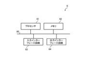
- FIG. 2 is a block diagram illustrating the hardware configuration of the control device 6 in the first embodiment.
- the control device 6 can be configured by, for example, a processor 61, a memory 62, an input interface circuit 63, and an output interface circuit 64, which are connected to each other by a bus 60.
- the processor 61 is a CPU (Central Processing Unit), an MPU (Micro Processing Unit), or the like.
- the memory 62 is a ROM (Read Only Memory), a RAM (Random Access Memory), or the like.
- the function of acquiring detection results from each of the first pressure sensing device 17 and the first temperature sensing device 18 by the control device 6 can be realized by the input interface circuit 63.
- the control device 6 may acquire detection results from both or one of the first pressure detection device 17 and the first temperature detection device 18 by wireless communication.
- the control device 6 has an input interface.
- a wireless communication interface circuit is included instead of the circuit 63 or together with the input interface circuit 63.
- the function that the control device 6 performs processing based on the detection results etc. from each of the first pressure sensing device 17 and the first temperature sensing device 18 is performed by the processor 61 reading out various programs, data, etc. stored in the memory 62. This can be achieved by executing
- the function of the control device 6 to control components such as the first compressor 10 and the first pressure reducing valve 14 can be realized by an output interface circuit 64, a processor 61, and a memory 62 that are connected by wire to the components. be.
- the control device 6 may control the components through wireless communication.
- the control device 6 includes a wireless communication interface circuit instead of the output interface circuit 64 or in addition to the output interface circuit 64. is included.
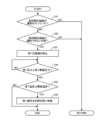
- FIG. 3 is a flowchart illustrating the flow of pressure adjustment processing by the refrigeration cycle apparatus 100 according to the first embodiment. Note that it is assumed that the first compressor 10 has started operating before step S1 in FIG. 3 .
- step S1 the control device 6 determines whether the secondary compressor 20 is operating. If the secondary compressor 20 is operating (step S1: YES), the refrigeration cycle device 100 moves the process to step S4. If the secondary compressor 20 is not operating (step S1: NO), the control device 6 determines in step S2 that an abnormality has occurred in the second refrigerant circuit 2 and the secondary compressor 20 cannot be operated. Determine whether it is in the state. If the secondary compressor 20 is in a state where it cannot be operated (step S2: YES), the refrigeration cycle device 100 moves the process to step S5.
- step S2 the control device 6 causes the secondary compressor 20 to start operating in step S3.
- step S3 the refrigeration cycle device 100 moves the process to step S4.
- step S4 the control device 6 determines whether the secondary compressor 20 is exhibiting the required refrigerating capacity. If the secondary side compressor 20 is not exhibiting the required refrigerating capacity (step S4: NO), the refrigeration cycle device 100 moves the process to step S6. If the secondary compressor 20 is exhibiting the required refrigerating capacity (step S4: YES), the refrigeration cycle device 100 returns the process to step S1. In this case, the refrigeration cycle apparatus 100 may return the process from step S4 to step S1 after a predetermined first cycle time has elapsed.
- step S5 the control device 6 stops the first compressor 10.
- step S6 the control device 6 determines whether the first pressure is equal to or higher than the first threshold pressure. If the first pressure is less than the first threshold pressure (step S6: NO), the refrigeration cycle device 100 returns the process to step S6. In this case, the refrigeration cycle apparatus 100 may return the process to step S6 after the predetermined second cycle time has elapsed. Note that the second cycle time is less than or equal to the first cycle time, but may be longer than the first cycle time. When the first pressure is less than the first threshold pressure, the refrigeration cycle apparatus 100 may return the process to step S1 instead of step S6.
- step S7 the control device 6 determines whether the first temperature detected by the first temperature detection device 18 is equal to or lower than the threshold temperature. do. If the first temperature is not equal to or lower than the threshold temperature (step S7: NO), the refrigeration cycle device 100 ends the pressure adjustment process.
- the refrigeration cycle device 100 may be provided with an alarm device, and the control device 6 causes the first refrigerant to be released from the first refrigerant circuit 1 by operating a safety valve or the like when the first temperature is not below a threshold temperature.
- the alarm device may be controlled to warn the user of the possibility of the accident.
- the control device 6 may stop the first compressor 10 when the first temperature is not below the threshold temperature and the first compressor 10 is operating.
- step S7 If the first temperature is below the threshold temperature (step S7: YES), the control device 6 controls the first pressure reducing valve 14 to open in step S8. At this time, the control device 6 may stop the first compressor 10 if the first compressor 10 is operating.
- the first refrigerant circuit 1 may include a valve other than the first pressure reducing valve 14, and in this case, the control device 6 controls the first refrigerant circuit when the first temperature is equal to or lower than the threshold temperature. All valves of No. 1 are controlled to be open. After the process of step S8, the refrigeration cycle device 100 ends the pressure adjustment process.
- the first object is heated by the first refrigerant in the evaporator 15, so that the first temperature increases. Then, the temperature of the first refrigerant in the evaporator 15 also increases over time. As a result, the pressure of the first refrigerant in the evaporator 15 increases over time, and there is a possibility that the pressure of the first refrigerant in the evaporator 15 may exceed the design pressure of the evaporator 15. To prevent such a situation, the volume of the evaporator 15 may be determined based on the time expected until the worker arrives. As described above, the threshold temperature is determined based on the volume of the evaporator 15, and becomes lower as the volume of the evaporator 15 is smaller.
- the refrigeration cycle apparatus 100 restarts operation after the process of step S8 is performed and after the maintenance of the refrigeration cycle apparatus 100, a large amount of liquid first refrigerant is supplied from the evaporator 15 to the heat source equipment. There is a possibility that it will flow into 3.
- the amount of the liquid first refrigerant may be an amount that cannot be separated by the gas-liquid separator 16.
- the refrigeration cycle apparatus 100 performs the following process to prevent liquid from returning to the first compressor 10 when restarting operation.
- the control device 6 closes the first pressure reducing valve 14, controls the first compressor 10 to operate at a predetermined lowest operating frequency, and allows the first refrigerant to flow through the first compressor 10.
- the volume of the gas-liquid separator 16 in the first embodiment is determined so that the liquid first refrigerant does not flow into the first compressor 10 when the first compressor 10 operates at the lowest operating frequency. shall be taken as a thing.
- a liquid-gas heat exchanger (not shown) may be provided between the first compressor 10 and the evaporator 15 to evaporate the first refrigerant.
- the first refrigerant circuit 1 may be provided with a flow path switching device such as a four-way valve (not shown) that changes the flow direction of the first refrigerant.
- control device 6 controls the flow path switching device to reverse the flow direction of the first refrigerant from the flow direction during the refrigeration operation, and causes the liquid receiver 13 to recover the first refrigerant, After that, the refrigeration cycle device 100 may restart the refrigeration operation.
- step S2 when there is a problem in the secondary compressor 20 (step S2: YES), the first compressor 10 is stopped and the first pressure is equal to or higher than the first threshold pressure (step S6: YES), and when the first temperature is below the threshold temperature (step S7: YES), the first pressure reducing valve 14 is opened to allow the liquid first refrigerant to flow into the evaporator 15, and the first refrigerant is
- the safety valve operates to reduce the pressure of the first refrigerant in order to protect the first refrigerant pipe 5, receiver 13, etc. in the first refrigerant circuit 1. There is also.
- Embodiment 2 The refrigeration cycle device 100 according to the second embodiment will be described in detail below.
- the same reference numerals are given to the same components as those in the first embodiment.
- descriptions of configurations similar to those in the first embodiment, functions similar to those in the first embodiment, etc. will be omitted unless there are special circumstances.
- FIG. 4 is a schematic diagram showing a configuration example of the refrigeration cycle device 100 according to the second embodiment.
- the first refrigerant circuit 1 in the second embodiment includes a first compressor 10, a low-stage heat exchanger 11A, a liquid receiver 13, a first pressure reducing valve 14, and an evaporator, which are sequentially connected by a first refrigerant pipe 5. 15 and a gas-liquid separator 16.
- Each of the first compressor 10, liquid receiver 13, first pressure reducing valve 14, evaporator 15, and gas-liquid separator 16 has the same configuration as in the first embodiment.
- the first compressor 10, the low-stage heat exchanger 11A, the liquid receiver 13, and the gas-liquid separator 16 are provided in a housing that forms the outer shell of the heat source device 3.
- FIG. 10 is a schematic diagram showing a configuration example of the refrigeration cycle device 100 according to the second embodiment.
- the first refrigerant circuit 1 in the second embodiment includes a first compressor 10, a low-stage heat exchanger 11A, a liquid receiver 13, a first pressure reducing
- the housing of the heat source device 3 is shown by a square with a dashed dotted line.
- the first pressure reducing valve 14 and the evaporator 15 are provided within the housing of the user equipment 4, as in the first embodiment. Note that in FIG. 4 as well, the housing of the user-side device 4 is indicated by a square with a chain double-dashed line.
- the first pressure reducing valve 14 may be provided outside the housing of the user equipment 4.
- FIG. 4 also shows an example in which the control device 6 is provided within the casing of the heat source device 3, the control device 6 may be provided within the casing of the user device 4, or a part of the control device 6 may be provided within the casing of the heat source device 3. The remaining portion may be provided in the user device 4.
- the low-stage heat exchanger 11A may be air-cooled or water-cooled.
- the air-cooled low-stage heat exchanger 11A is, for example, a plate-fin tube heat exchanger.
- the water-cooled low-stage heat exchanger 11A is a shell and tube heat exchanger, a plate heat exchanger, a double pipe heat exchanger, or the like.
- the low-stage heat exchanger 11A is an example of a first heat exchanger.
- air, water, or the like that cools the first refrigerant in the low-stage heat exchanger 11A is an example of the second object.
- the refrigeration cycle device 100 includes a refrigerant flow path 8 instead of the second refrigerant circuit 2.
- the refrigerant flow path 8 is connected to the first refrigerant circuit 1 and allows the first refrigerant to flow therethrough.
- the refrigerant flow path 8 includes a high-stage compressor 20A, a high-stage condenser 21A, a high-stage pressure reducing valve 22A, and a liquid receiver 13, which are connected in sequence by the first refrigerant pipe 5.
- the refrigerant flow path 8 is arranged within a casing that forms the outer shell of the heat source device 3 .
- the high-stage compressor 20A is a scroll type, rotary type, reciprocating type, or screw type compressor, and is an inverter compressor whose capacity can be controlled by an inverter.
- the high-stage compressor 20A compresses the first refrigerant from the low-stage heat exchanger 11A and the first refrigerant from the high-stage pressure reducing valve 22A, which will be described later.
- the high stage compressor 20A is an example of a second compressor.
- the high-stage condenser 21A may be an air-cooled condenser or a water-cooled condenser.
- Examples of the air-cooled high-stage condenser 21A include a plate-fin tube heat exchanger, a parallel flow condenser, and the like.
- Examples of the water-cooled high-stage condenser 21A include a shell-and-tube heat exchanger, a plate heat exchanger, a double-tube heat exchanger, and the like.
- the high-stage condenser 21A cools and condenses the second refrigerant by exchanging heat between the second refrigerant and a fifth object such as air or water.
- the gaseous first refrigerant discharged from the high-stage compressor 20A may be in a critical state, and the first refrigerant in the high-stage condenser 21A is heated by the fifth object in the critical state. be taken away.
- a water sprinkler (not shown) may be installed to cool the first refrigerant.
- the high-stage condenser 21A is an example of a second heat exchanger.
- the high-stage side pressure reducing valve 22A is an electronic expansion valve, a temperature expansion valve, or the like.
- the high-stage pressure reducing valve 22A is an example of a second valve.
- the high-stage pressure reducing valve 22A reduces the pressure of the first refrigerant until it liquefies.
- the first refrigerant after being depressurized by the high-stage pressure reducing valve 22A is in a two-phase state.
- the first refrigerant which is a saturated gas among the two phases, is mixed with the gaseous first refrigerant of the first refrigerants flowing out from the low-stage heat exchanger 11A, and the gaseous first refrigerant after mixing is It is sucked into the high-stage compressor 20A.
- the first refrigerant that is a saturated liquid among the first refrigerants after the pressure reduction by the high-stage pressure reducing valve 22A and the liquid first refrigerant among the first refrigerants that have flowed out from the low-stage heat exchanger 11A are the receiving liquid. It is stored in the container 13. Note that the liquid receiver 13 is disposed downstream of the low-stage heat exchanger 11A and the high-stage pressure reducing valve 22A, and upstream of the first pressure reducing valve 14.
- both or one of the first refrigerant circuit 1 and refrigerant flow path 8 in the second embodiment includes an oil separator, an oil return circuit from the oil separator, a check valve, a service operation valve, and a site. At least one of safety devices such as a glass, a strainer, a dryer, and a high-voltage switch may be installed. Further, the first refrigerant circuit 1 may be provided with a four-way valve, a three-way valve, or the like for switching the flow direction of the first refrigerant in order to defrost the evaporator 15.
- the first refrigerant in the form of a saturated liquid flows out from the heat source device 3. Then, due to the pressure loss of the first refrigerant in the first refrigerant pipe 5 that connects the heat source device 3 and the user-side device 4, flash gas may be generated upstream of the first pressure reducing valve 14. For this reason, the refrigeration cycle device 100 may include a subcooling heat exchanger or a liquid gas heat exchanger (not shown).
- the control device 6 controls the first compressor 10, the first pressure reducing valve 14, etc. as in the first embodiment, and also controls the high stage compressor 20A and the high stage pressure reducing valve 22A.
- the control device 6 is connected by wire to each component such as the high-stage compressor 20A and the high-stage pressure reducing valve 22A, and transmits a control signal to each component, and each component receives the received control signal. operate on the basis of Note that the control device 6 may control at least one component of the high-stage compressor 20A, the high-stage pressure reducing valve 22A, etc. by wireless communication.
- the first refrigerant circuit 1 is provided with a first pressure detection device 17, and the first pressure detection device 17 detects the first pressure. Further, the evaporator 15 is provided with a first temperature detection device 18, and the first temperature detection device 18 detects the first temperature.
- the control device 6 acquires detection results from the first pressure sensing device 17 and the first temperature sensing device 18, as in the first embodiment. Then, when the first pressure detected by the first pressure detection device 17 is equal to or higher than the first threshold pressure, and the first temperature detected by the first temperature detection device 18 is equal to or lower than the threshold temperature, the control device 6 controls the control device 6. In this case, the first pressure reducing valve 14 is opened.
- the threshold temperature in the second embodiment is equal to or lower than the condensation temperature of the first refrigerant, as in the first embodiment.
- the threshold temperature in the first embodiment was set by determining the temperature of the determination target in the primary heat exchanger 11, but the threshold temperature in the second embodiment was set in the low stage heat exchanger 11A. It is set by determining water, air, or the fifth object in the high-stage condenser 21A.
- the control device 6 in the second embodiment may determine at any time whether the first pressure is equal to or higher than the first threshold pressure, but if the high-stage compressor 20A is in a state where it cannot be operated, It may be determined whether the pressure is equal to or higher than a first threshold pressure.
- the control device 6 can determine whether the high-stage compressor 20A is in a state where it cannot be operated by determining whether an overcurrent is detected or not. Note that the overcurrent occurs when the high-pressure pressure switch is activated or when the motor of the high-stage compressor 20A breaks down.
- the control device 6 causes the high stage compressor 20A to start operating. However, it may be determined whether the first pressure is equal to or higher than the first threshold pressure at the same time as the high-stage compressor 20A starts operating, or instead of starting the operation of the high-stage compressor 20A. .
- the hardware configuration of the control device 6 in the second embodiment is illustrated in FIG. 2, as in the first embodiment. Further, the contents of the hardware configuration of the control device 6 of the second embodiment are the same as the contents of the hardware configuration of the control device 6 of the first embodiment described with reference to FIG.
- FIG. 5 is a flowchart illustrating the flow of pressure adjustment processing by the refrigeration cycle apparatus 100 according to the second embodiment. Note that it is assumed that the first compressor 10 has started operating before step S11 in FIG.
- step S11 the control device 6 determines whether the high-stage compressor 20A is operating. If the high-stage compressor 20A is operating (step S11: YES), the refrigeration cycle device 100 returns the process to step S11. The refrigeration cycle device 100 may return the process to step S11 after the first cycle time has elapsed.
- step S11 the control device 6 determines in step S12 whether the high stage compressor 20A is in a state where it cannot be operated. When the high stage compressor 20A is in a state where it cannot be operated (step S12: YES), the refrigeration cycle apparatus 100 moves the process to step S14. When the high stage compressor 20A is in a state where it can be operated (step S12: NO), the control device 6 causes the high stage compressor 20A to start operating in step S13. After the process in step S13, the refrigeration cycle device 100 returns the process to step S11. At this time, the refrigeration cycle apparatus 100 may return the process to step S11 after the first cycle time has elapsed. Note that, after the process in step S13, the refrigeration cycle apparatus 100 may move the process to step S15 instead of step S11.
- step S14 to step S17 is similar to the processing from step S5 to step S8 described above.
- the process of the refrigeration cycle apparatus 100 when the operation is restarted after the process of step S17 and after the maintenance of the refrigeration cycle apparatus 100 is similar to the process of the refrigeration cycle apparatus 100 when the operation is restarted in the first embodiment described above. be.
- the volume of the gas-liquid separator 16 in the second embodiment is such that the liquid first refrigerant flows into the first compressor 10 when the first compressor 10 operates at the lowest operating frequency. It may be stipulated not to do so.
- a liquid-gas heat exchanger (not shown) may be provided between the first compressor 10 and the evaporator 15 to evaporate the first refrigerant.
- the first refrigerant circuit 1 may be provided with a flow path switching device as in the first embodiment. Then, before restarting the operation, the control device 6 controls the flow path switching device to reverse the flow direction of the first refrigerant from the flow direction during the refrigeration operation, and collects the first refrigerant into the receiver 13. After that, the refrigeration cycle device 100 may restart operation.
- Embodiment 3 The refrigeration cycle device 100 according to the third embodiment will be described in detail below. Note that in the third embodiment, the same reference numerals are given to the same components as those in the first to second embodiments. Furthermore, in Embodiment 3, there are no special circumstances regarding the configuration similar to the configuration in Embodiment 1 to Embodiment 2, and the same functions as in Embodiment 1 to Embodiment 2. The explanation will be omitted as far as possible.
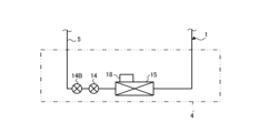
- FIG. 6 is a schematic diagram showing a configuration example of the user device 4 in the third embodiment.
- the first refrigerant circuit 1 of the third embodiment includes a bypass path 1A through which the first refrigerant flowing out from the liquid receiver 13 bypasses the first pressure reducing valve 14.
- a first on-off valve 14A is provided in the bypass path 1A.
- the first on-off valve 14A is an electronic expansion valve, a temperature expansion valve, a solenoid valve, or the like.
- the first on-off valve 14A allows the first refrigerant to flow from the receiver 13 to the evaporator 15 in the open state, and blocks the flow of the first refrigerant from the receiver 13 to the evaporator 15 in the closed state.
- the first on-off valve 14A is an example of a first valve.
- FIG. 6 shows an example in which the first pressure reducing valve 14, the bypass path 1A, and the first on-off valve 14A are arranged within the housing of the user equipment 4, the first pressure reducing valve 14, the bypass path 1A,
- the first on-off valve 14A may be placed outside the user device 4.
- the first pressure reducing valve 14 may be arranged within the casing of the user equipment 4, and a portion of the bypass path 1A may be arranged within the casing of the user equipment 4.
- the first on-off valve 14A may be placed inside the housing of the user device 4, or may be placed outside the user device 4.
- the control device 6 in the third embodiment controls the first pressure reducing valve 14 to be open when the first pressure is equal to or higher than the first threshold pressure and the first temperature is equal to or lower than the threshold temperature.
- the first pressure reducing valve 14 is controlled to be open, and the first on-off valve 14A is controlled to be open.
- the first refrigerant can be transferred to the evaporator 15. can. Therefore, an increase in the pressure of the first refrigerant in the first refrigerant circuit 1 can be suppressed.
- Embodiment 4 The refrigeration cycle device 100 according to Embodiment 4 will be described in detail below. Note that in the fourth embodiment, the same reference numerals are given to the same components as those in the first to third embodiments. Furthermore, in Embodiment 4, there are no special circumstances regarding the configuration similar to the configuration in Embodiment 1 to Embodiment 3, and the same functions as in Embodiment 1 to Embodiment 3. The explanation will be omitted as far as possible.
- FIG. 7 is a schematic diagram showing a configuration example of the user-side device 4 in the fourth embodiment.
- the configuration of the refrigeration cycle apparatus 100 according to the fourth embodiment is the same as that of the first to third embodiments except for the user equipment 4.
- FIG. 7 shows a case where the first refrigerant circuit 1 does not include the bypass passage 1A
- the first refrigerant circuit 1 of the fourth embodiment may include the bypass passage 1A.
- Refrigeration cycle device 100 of Embodiment 4 further includes a second on-off valve 14B.
- the second on-off valve 14B is, for example, a solenoid valve.
- the second on-off valve 14B is provided in the first refrigerant circuit 1 upstream of the first pressure reducing valve 14, allows the first refrigerant to flow to the evaporator 15 in an open state, and blocks the flow of the first refrigerant in a closed state. .
- the second on-off valve 14B is an example of a third valve.
- FIG. 7 shows an example in which the first pressure reducing valve 14 and the second on-off valve 14B are arranged within the housing of the user-side device 4, the first pressure-reducing valve 14 and the second on-off valve 14B are It may be placed outside the side device 4. Alternatively, the first pressure reducing valve 14 may be placed inside the housing of the user device 4, and the second on-off valve 14B may be placed outside the user device 4.
- the bypass path 1A may be a path that causes the first refrigerant to bypass the first pressure reducing valve 14 and the second on-off valve 14B.
- the bypass path 1A may be a path that allows the first refrigerant to bypass only the first pressure reducing valve 14, and the second on-off valve 14B is provided upstream of the first pressure reducing valve 14 and the first on-off valve 14A. It's okay to be hit. That is, the second on-off valve 14B may be provided upstream of the position where the first refrigerant flowing out from the liquid receiver 13 flows into the bypass path 1A.
- the control device 6 controls the second on-off valve 14B to open when the first pressure is equal to or higher than the first threshold pressure and the first temperature is equal to or lower than the threshold temperature.
- the refrigeration cycle apparatus 100 circulates a first refrigerant, which is carbon dioxide, through the first refrigerant circuit 1, and cools a first object with the first refrigerant.
- the refrigeration cycle device 100 includes a first compressor 10, a first heat exchanger, an evaporator 15, a first valve, a first pressure detection device 17, a first temperature detection device 18, and a control device 6.
- the first compressor 10 compresses and discharges the first refrigerant.
- the first heat exchanger causes the first refrigerant discharged from the first compressor 10 to exchange heat with a second object, thereby cooling the first refrigerant.
- the evaporator 15 causes the first refrigerant to exchange heat with the first object.
- the first valve is provided upstream of the evaporator 15 in the first refrigerant circuit 1, and in an open state reduces the pressure of the first refrigerant and allows the reduced pressure first refrigerant to flow through the evaporator 15.
- the first pressure detection device 17 detects a first pressure that is the pressure of the first refrigerant between the downstream side of the first compressor 10 and the first valve.
- the first temperature detection device 18 detects a first temperature that is the temperature of the first object in the evaporator 15 .
- the control device 6 controls the first compressor 10 and the first valve.
- the control device 6 controls the first valve to open when the first pressure is equal to or higher than a predetermined first threshold pressure and the first temperature is equal to or lower than a predetermined threshold temperature. .
- the control device 6 controls the first valve to be in the open state, so that the first refrigerant evaporates. It flows into the vessel 15.
- the first temperature is below the threshold temperature, and as the first refrigerant exchanges heat with the first target in the evaporator 15, the first pressure of the first refrigerant in the first refrigerant circuit 1 is reduced when the first valve is closed. This is reduced compared to the case where the first refrigerant does not flow into the evaporator 15. Therefore, the operation of the safety valve is suppressed, and damage to the components in the first refrigerant circuit 1 is suppressed. Further, since the operation of the safety valve is suppressed, the release of the first refrigerant is suppressed, and therefore, the sudden exposure of the worker, user, etc. to the first refrigerant is suppressed. Therefore, safety is improved.
- the threshold temperature in Embodiments 1 to 4 is a temperature lower than the condensation temperature of the first refrigerant when the first refrigerant is in an equal pressure state in the first refrigerant circuit 1.
- the first refrigerant is condensed in the primary heat exchanger 11 or the refrigerant heat exchanger 12, and in the second embodiment, the first refrigerant is condensed in the high-stage condenser 21A.
- the first refrigerant is further cooled in the evaporator 15 by setting the temperature to be lower than the condensation temperature of the refrigerant. Therefore, the refrigeration cycle device 100 can further reduce the first pressure. Therefore, the refrigeration cycle device 100 can suppress damage to the components in the first refrigerant circuit 1 or the operation of the safety valve.
- the threshold temperature in Embodiments 1 to 4 is the amount of the first refrigerant flowing into the evaporator 15 when the first compressor 10 is stopped and the first valve is open. is set so that it does not exceed the volume of the evaporator 15. Thereby, the evaporator 15 can accommodate the first refrigerant, and damage to the evaporator 15 is also suppressed.
- the first compressor 10, first heat exchanger, first valve, and evaporator 15 in Embodiments 1 to 4 are connected by a first refrigerant pipe 5 through which a first refrigerant flows.
- the first threshold pressure is lower than the design pressure of each of the first compressor 10, the first heat exchanger, the first valve, the evaporator 15, and the first refrigerant pipe 5, and the safety valve or the rupture disc is activated.
- the pressure is less than the pressure.
- the control device 6 controls the first valve to be open so that the first refrigerant evaporates. Guided to vessel 15.
- the first refrigerant reaches the evaporator.
- the first pressure is reduced. Therefore, damage to the components in the first refrigerant circuit 1 can be suppressed, and operation of safety valves and the like can be suppressed.
- the refrigeration cycle apparatus 100 stores the first refrigerant downstream of the first heat exchanger and upstream of the first valve in the first refrigerant circuit 1. It further includes a liquid receiver 13. Thereby, the refrigeration cycle apparatus 100 can reduce the first pressure in the first refrigerant pipe 5 and the like, and can suppress damage to the first refrigerant pipe 5 and the like or the operation of the safety valve.
- the first compressor 10, the first heat exchanger, the liquid receiver 13, the first valve, and the evaporator 15 in Embodiments 1 to 4 are connected by a first refrigerant pipe 5 through which the first refrigerant flows. has been done.
- the first threshold pressure is lower than the design pressure of each of the first compressor 10, the first heat exchanger, the liquid receiver 13, the first valve, the evaporator 15, and the first refrigerant pipe 5, and the safety valve or The pressure is below that at which the rupture disc is activated.
- the control device 6 controls the first valve to be open so that the first refrigerant evaporates. Guided to vessel 15.
- the first refrigerant reaches the evaporator.
- the first pressure is reduced. Therefore, damage to the components in the first refrigerant circuit 1 can be suppressed, and operation of safety valves and the like can be suppressed.
- the refrigeration cycle apparatus 100 further includes a second refrigerant circuit 2 that circulates a second refrigerant.
- the second target is the second refrigerant.
- the second refrigerant circuit 2 includes a second compressor, a second heat exchanger, a second valve, and the first heat exchanger.
- the second compressor compresses the second refrigerant.
- the second heat exchanger causes the second refrigerant discharged from the second compressor to exchange heat with a third object, thereby condensing the second refrigerant.
- the second valve reduces the pressure of the second refrigerant condensed in the second heat exchanger.
- the first heat exchanger exchanges heat between the second refrigerant whose pressure has been reduced by the second valve and the first refrigerant discharged from the first compressor 10, condenses the first refrigerant, and evaporates the second refrigerant. .
- the first refrigerant is cooled by the second refrigerant, so the first pressure is reduced. Therefore, damage to the components in the first refrigerant circuit 1 or operation of the safety valve is suppressed.
- the first refrigerant circuit 1 in Embodiment 1, Embodiment 3, and Embodiment 4 further includes a primary heat exchanger 11.
- the primary heat exchanger 11 cools the first refrigerant by exchanging heat with the fourth object. Since the first refrigerant is cooled in the primary heat exchanger 11 and the first heat exchanger, the first pressure is reduced. Therefore, the refrigeration cycle device 100 can suppress damage to the components in the first refrigerant circuit 1 or the operation of the safety valve.
- the control device 6 determines whether the first pressure is equal to or higher than the first threshold pressure when the second compressor is not exhibiting the required refrigerating capacity. If the first pressure is equal to or higher than the first threshold pressure and the first temperature is equal to or lower than the threshold temperature, the first valve is controlled to be open. Thereby, even if a problem occurs in the second refrigerant circuit 2 and the first refrigerant cannot be cooled by the second refrigerant, an increase in the first pressure can be suppressed. Therefore, the refrigeration cycle device 100 can suppress damage to the components in the first refrigerant circuit 1 or the operation of the safety valve.
- the refrigeration cycle apparatus 100 further includes a refrigerant flow path 8 connected to the first refrigerant circuit 1 and through which the first refrigerant flows.
- the refrigerant flow path 8 has a second compressor, a second heat exchanger, and a second valve.
- the second compressor compresses the first refrigerant.
- the second heat exchanger exchanges heat with the first refrigerant discharged from the second compressor and condenses the first refrigerant.
- the second valve reduces the pressure of the first refrigerant condensed in the second heat exchanger.
- the liquid receiver 13 is provided downstream of the second valve.
- the second compressor compresses the first refrigerant from the first heat exchanger and the second valve.
- the control device 6 in Embodiments 1 to 4 stops the first compressor when the second compressor cannot be operated, and determines whether the first pressure is equal to or higher than the first threshold pressure. is determined, and if the first pressure is equal to or higher than the first threshold pressure and the first temperature is equal to or lower than the threshold temperature, the first valve is controlled to be in an open state. Thereby, even if the second compressor cannot operate and the first refrigerant is not cooled, an increase in the first pressure can be suppressed. Therefore, the refrigeration cycle device 100 can suppress damage to the components in the first refrigerant circuit 1 or the operation of the safety valve.
- the first valve in Embodiments 1 to 4 is the first pressure reducing valve 14 that reduces the pressure of the first refrigerant flowing to the evaporator 15 in the open state. As a result, the pressure of the first refrigerant flowing into the evaporator 15 is reduced. Therefore, damage to the evaporator 15 can be suppressed.
- the refrigeration cycle apparatus 100 further includes a first pressure reducing valve 14.
- the first pressure reducing valve 14 is provided upstream of the evaporator 15 in the first refrigerant circuit 1, and in an open state allows the first refrigerant to flow through the evaporator 15 and reduces the pressure of the first refrigerant.
- the first refrigerant circuit 1 includes a bypass path 1A through which the first refrigerant flowing to the evaporator 15 bypasses the first pressure reducing valve 14.
- the first valve is provided in the bypass path 1A.
- the control device 6 controls the first pressure reducing valve 14 to open when the first pressure is equal to or higher than the first threshold pressure and the first temperature is equal to or lower than the threshold temperature.
- the first refrigerant can be transferred to the evaporator 15 by opening the first pressure reducing valve 14 . Therefore, when the first pressure is above the first threshold pressure and the first temperature is below the threshold temperature, the first refrigerant flows into the evaporator 15 in a state where the pressure is reduced by the first pressure reducing valve 14. Therefore, the pressure of the first refrigerant in the first refrigerant circuit 1 is reduced. Therefore, the refrigeration cycle device 100 can suppress damage to the components in the first refrigerant circuit 1 or suppress the operation of a safety valve or the like.
- the refrigeration cycle apparatus 100 may further include the following second on-off valve 14B.
- the second on-off valve 14B is provided in the first refrigerant circuit 1 upstream of the first pressure reducing valve 14, allows the first refrigerant to flow to the evaporator 15 in an open state, and blocks the flow of the first refrigerant in a closed state.
- the control device 6 controls the second on-off valve 14B to open when the first pressure is equal to or higher than the first threshold pressure and the first temperature is equal to or lower than the threshold temperature.
- Embodiment 5 The refrigeration cycle device 100 according to the fifth embodiment will be described in detail below.
- the same reference numerals are given to the same components as those in the first to fourth embodiments.
- Embodiment 5 there are no special circumstances regarding the configuration similar to the configuration in Embodiment 1 to Embodiment 4, and the same functions as in Embodiment 1 to Embodiment 4. The explanation will be omitted as far as possible.
- FIG. 8 is a schematic diagram showing a configuration example of the refrigeration cycle device 100 according to the fifth embodiment.
- a first pressure sensing device 17 is provided at the inlet of the liquid receiver 13. Note that the first pressure sensing device 17 may be provided within the liquid receiver 13.
- the first pressure detection device 17 of the fifth embodiment detects the first pressure of the first refrigerant in the liquid receiver 13.
- the refrigeration cycle device 100 of the fifth embodiment further includes a second pressure detection device 17A that detects the first pressure of the first refrigerant discharged from the first compressor 10.
- the second pressure detection device 17A is provided, for example, in the first refrigerant pipe 5 on the discharge side of the first compressor 10.
- the configuration of the refrigeration cycle apparatus 100 according to the fifth embodiment shown in FIG. 8 is the same as that of the refrigeration cycle apparatus 100 according to the first embodiment shown in FIG. It is similar to the configuration.
- the user-side equipment 4 of the refrigeration cycle apparatus 100 according to the fifth embodiment is the same as that of the third to fourth embodiments, and may be the one shown in FIG. 6 or FIG. 7.
- the hardware configuration of the control device 6 according to the fifth embodiment is illustrated in FIG. 2 as in the first to fourth embodiments.
- the control device 6 of the fifth embodiment determines whether the first pressure obtained by the first pressure detection device 17 is equal to or higher than the first threshold pressure when the first compressor 10 is stopped.
- the first threshold pressure in the first embodiment is determined based on the design pressure of the liquid receiver 13. That is, the first threshold pressure is a pressure lower than the design pressure of the liquid receiver 13.
- the control device 6 determines whether the first temperature is equal to or lower than the threshold temperature, and when the first temperature is equal to or lower than the threshold temperature, the control device 6 controls the first pressure reducing valve 14. Control to open state.
- the control device 6 of the fifth embodiment determines whether the first pressure detected by the second pressure detection device 17A is equal to or higher than the second threshold pressure.
- the second threshold pressure is determined based on the design pressure of the first compressor 10 and the first refrigerant pipe 5. That is, the second threshold pressure is set to be less than the design pressure of the first compressor 10 and less than the design pressure of the first refrigerant pipe 5. Note that the second threshold pressure is a pressure greater than or equal to the first threshold pressure.
- FIG. 9 is a flowchart illustrating the flow of pressure adjustment processing by the refrigeration cycle apparatus 100 according to the fifth embodiment.
- the processing from step S21 to step S22 is similar to the processing from step S1 to step S2 described above. If the secondary compressor 20 is in a state where it cannot be operated in step S22 (step S22: YES), the refrigeration cycle device 100 moves the process to step S23.
- the process in step S23 is similar to the process in step S5.
- step S22 determines whether the first compressor 10 is stopped in step S24. If the first compressor 10 is stopped (step S24: YES), the refrigeration cycle device 100 moves the process to step S26.
- the processing from step S26 to step S28 is similar to the processing from step S6 to step S8 described above.
- step S25 the control device 6 determines whether the first pressure obtained by the second pressure detection device 17A is equal to or higher than the second threshold pressure. Determine whether or not.
- step S25: NO If the first pressure obtained by the second pressure detection device 17A is not equal to or higher than the second threshold pressure (step S25: NO), the refrigeration cycle device 100 returns the process to step S21.
- step S25: YES When the first pressure obtained by the second pressure detection device 17A is equal to or higher than the second threshold pressure (step S25: YES), the refrigeration cycle device 100 moves the process to step S26.
- the pressure of the refrigerant in the discharge portion of the first compressor 10 and the liquid receiver 13 is substantially equal, but in step S23, the pressure of the refrigerant is If the first compressor 10 has stopped, or if it is determined in step S24 that the first compressor 10 has stopped, a check valve (not shown) in the discharge portion of the first compressor 10 will cause the The pressure of the refrigerant in the liquid container 13 may be higher than the pressure of the refrigerant in the discharge section of the first compressor 10.
- step S26 the control device 6 compares the first pressure in the liquid receiver 13 with the first threshold pressure, and when the first pressure is equal to or higher than the first threshold pressure, the refrigeration cycle device 100 By performing the process of step S28 after passing through step S27, the first pressure in the liquid receiver 13 is made lower than the design pressure of the liquid receiver 13 even when the first compressor 10 is not operating. can be maintained.
- the first pressure detection device 17 of the fifth embodiment detects the first pressure of the first refrigerant in the liquid receiver 13.
- the control device 6 opens the first valve when the first pressure is equal to or higher than the first threshold pressure and the first temperature is equal to or lower than the threshold temperature while the first compressor 10 is stopped. control to the state.
- the liquid receiver 13 Even if the first pressure of the first refrigerant in the liquid receiver 13 increases while the first compressor 10 is stopped, if the first temperature is equal to or lower than the threshold temperature, the liquid receiver 13 The first refrigerant inside flows to the evaporator 15. Therefore, an excessive increase in the first pressure in the liquid receiver 13 is suppressed, and the liquid receiver 13 can be protected.
- the refrigeration cycle device 100 further includes a second pressure detection device 17A that detects the first pressure of the first refrigerant discharged from the first compressor 10.
- the control device 6 controls the , determining whether the first pressure of the first refrigerant in the liquid receiver 13 is equal to or higher than the first threshold pressure, and the first pressure of the first refrigerant in the liquid receiver 13 is equal to or higher than the first threshold pressure, Further, when the first temperature is equal to or lower than the threshold temperature, the first valve is controlled to be in an open state.
- the first threshold pressure is determined based on the design pressure of the liquid receiver 13.
- the second threshold pressure is determined based on the design pressure of the first compressor 10.
- the first pressure may change when the first refrigerant flows from the first compressor 10 to the liquid receiver 13. However, when the first pressure of the first refrigerant discharged from the first compressor 10 is high, there is a possibility that the first pressure of the first refrigerant flowing into the liquid receiver 13 exceeds the design pressure of the liquid receiver 13.
- the control device 6 is configured such that the first pressure detected by the second pressure detection device 17A is equal to or higher than the second threshold pressure, the first pressure detected by the first pressure detection device 17 is equal to or higher than the first threshold pressure, and , when the first temperature is below the threshold temperature, the first refrigerant flows through the evaporator 15 in order to open the first valve. Therefore, the liquid receiver 13 is protected together with the evaporator 15.
- Embodiment 6 The refrigeration cycle device 100 according to the sixth embodiment will be described in detail below.
- the same reference numerals are given to the same components as those in the first to fifth embodiments.
- Embodiment 6 there are no special circumstances regarding the configuration similar to the configuration in Embodiment 1 to Embodiment 5, and the same functions as in Embodiment 1 to Embodiment 5. The explanation will be omitted as far as possible.
- FIG. 10 is a schematic diagram showing a configuration example of a refrigeration cycle device 100 according to Embodiment 6.
- a first pressure sensing device 17 is provided in the liquid receiver 13.
- the first pressure detection device 17 of the sixth embodiment detects the first pressure of the first refrigerant in the liquid receiver 13.
- the configuration of refrigeration cycle apparatus 100 according to Embodiment 6 is similar to the configuration of refrigeration cycle apparatus 100 according to Embodiment 2 shown in FIG. 4, except for the location where first pressure detection device 17 is arranged.
- the configuration of the refrigeration cycle device 100 according to the sixth embodiment may be shown in FIG. 4 similarly to the second embodiment. That is, the first pressure sensing device 17 may be provided in the first refrigerant pipe 5 on the discharge side of the first compressor 10.
- the refrigeration cycle device 100 according to the sixth embodiment includes a first pressure detection device 17 provided in the liquid receiver 13 and a defect provided in the first refrigerant pipe 5 on the discharge side of the first compressor 10. It may also be provided with other pressure sensing devices shown.
- the user-side equipment 4 of the refrigeration cycle apparatus 100 according to the sixth embodiment is the same as those in the third to fourth embodiments, and may be the one shown in FIG. 6 or FIG. 7.
- the hardware configuration of the control device 6 in the sixth embodiment is illustrated in FIG. 2 as in the first to fifth embodiments.
- the first pressure detection device 17 of the sixth embodiment detects the first pressure of the first refrigerant in the liquid receiver 13. Then, the control device 6 determines that when the first compressor 10 is stopped, the first pressure obtained by the first pressure detection device 17 is equal to or higher than the first threshold pressure, and the first temperature is the threshold value. When the temperature is below the temperature, the first pressure reducing valve 14 is controlled to be open, and the first refrigerant is allowed to flow through the evaporator 15 .
- FIG. 11 is a flowchart illustrating the flow of pressure adjustment processing by the refrigeration cycle apparatus 100 according to the sixth embodiment.
- the processing from step S31 to step S32 is similar to the processing from step S11 to step S12 described above. If the high stage compressor 20A is in a state where it cannot be operated in step S32 (step S32: YES), the refrigeration cycle apparatus 100 moves the process to step S33.
- the processing from step S33 to step S36 is similar to the processing from step S14 to step S17. If the high-stage compressor 20A is in a state where it can be operated in step S32 (step S32: NO), the refrigeration cycle apparatus 100 returns the process to step S31.
- the first pressure detection device 17 of the sixth embodiment detects the first pressure in the liquid receiver 13.
- the control device 6 closes the first valve. Control to open state.
- First refrigerant circuit 1A bypass path, 2. Second refrigerant circuit, 3. Heat source equipment, 4. Utilization side equipment, 5. First refrigerant piping, 6. Control device, 7. Second refrigerant piping, 8. Refrigerant flow path, 10. First compression.
Landscapes
- Engineering & Computer Science (AREA)
- Physics & Mathematics (AREA)
- Mechanical Engineering (AREA)
- Thermal Sciences (AREA)
- General Engineering & Computer Science (AREA)
- Air Conditioning Control Device (AREA)
Abstract
冷凍サイクル装置は、第1冷媒を第1冷媒回路に循環させ、第1冷媒によって第1対象を冷却する。冷凍サイクル装置は、第1圧縮機と第1熱交換器と蒸発器と第1弁と第1圧力検知装置と第1温度検知装置と制御装置と受液器と第2冷媒回路とを備える。第2冷媒回路は第2冷媒を循環させる。第2冷媒回路は、第2圧縮機と第2熱交換器と第2弁と第1熱交換器とを有する。第1圧縮機は第1冷媒を圧縮する。第1熱交換器は第1冷媒を第2冷媒と熱交換させる。蒸発器は第1冷媒を第1対象と熱交換させる。第1弁は、第1冷媒回路において蒸発器の上流側に設けられ、開状態において蒸発器に第1冷媒を流通させる。第1圧力検知装置は、第1冷媒の圧力である第1圧力を検知する。第1温度検知装置は、蒸発器における第1対象の温度である第1温度を検知する。制御装置は、第1圧縮機および第1弁を制御する。第2圧縮機は第2冷媒を圧縮する。第2熱交換器は第2冷媒を第3対象と熱交換させ、第2弁は第2冷媒を減圧する。制御装置は、第1圧力が予め定められた第1閾値圧力以上であって、且つ、第1温度が予め定められた閾値温度以下である場合には、第1弁を開状態に制御する。
Description
本開示は、二酸化炭素を冷媒とする冷凍サイクル装置に関するものである。
二酸化炭素(R744)を冷媒とする冷凍サイクル装置では、冷媒の圧力が例えば10[MPa]などとなり、例えばフロンなどを冷媒とする場合に比べ、冷媒の圧力が高くなる。そのため、R744を冷媒とする冷凍サイクル装置における熱交換器、容器および冷媒配管等の部品には、高い耐圧性が求められる。また、このような冷凍サイクル装置には、設置環境下で冷媒の圧力が設計圧力を超えないようにするための各種構成要素が設けられる場合がある(例えば、特許文献1参照)。このような構成要素としては、冷媒回路における冷媒の圧力が高くなった際に、冷媒を外部へ放出するための安全弁などがある。
しかし、安全弁の作動によって、冷凍サイクル装置の外郭を形成する筐体内に大量のガス冷媒が溜まり、作業員などが、冷凍サイクル装置に対する作業時において、急激に大量のガス冷媒を浴びる可能性がある。また、冷媒の放出後には、冷媒の冷媒回路への再封入などの処理が必要となり、冷凍サイクル装置が運転を再開するまでに時間がかかる場合がある。
本開示は、上記課題を解決するためになされたものであり、安全弁の作動前に冷媒の圧力を低減させることにより、冷凍サイクル装置の破損の抑制と、運転再開の迅速化と、安全性の向上とを図る冷凍サイクル装置を提供することを目的とする。
本開示に係る冷凍サイクル装置は、二酸化炭素である第1冷媒を第1冷媒回路に循環させて、前記第1冷媒によって第1対象を冷却する冷凍サイクル装置であって、前記第1冷媒を圧縮する第1圧縮機と、前記第1圧縮機から吐出された前記第1冷媒を第2対象と熱交換させ、前記第1冷媒を冷却する第1熱交換器と、前記第1冷媒を前記第1対象と熱交換させる蒸発器と、前記第1冷媒回路において前記蒸発器の上流側に設けられ、開状態において前記第1冷媒を減圧して、前記蒸発器に減圧した前記第1冷媒を流通させる第1弁と、前記第1圧縮機の下流側と前記第1弁との間の前記第1冷媒の圧力である第1圧力を検知する第1圧力検知装置と、前記蒸発器における前記第1対象の温度である第1温度を検知する第1温度検知装置と、前記第1圧縮機および前記第1弁を制御する制御装置と、第2冷媒を循環させる第2冷媒回路と、を備え、前記第2対象は前記第2冷媒であって、前記第2冷媒回路は、前記第2冷媒を圧縮する第2圧縮機と、前記第2圧縮機から吐出された前記第2冷媒を第3対象と熱交換させ、前記第2冷媒を凝縮させる第2熱交換器と、前記第2熱交換器において凝縮した前記第2冷媒を減圧する第2弁と、前記第1熱交換器と、を有し、前記第1熱交換器は、前記第2弁で減圧された前記第2冷媒と、前記第1圧縮機から吐出された前記第1冷媒とを熱交換させ、前記第1冷媒を凝縮させると共に前記第2冷媒を蒸発させ、前記制御装置は、前記第1圧力が予め定められた第1閾値圧力以上であって、且つ、前記第1温度が予め定められた閾値温度以下である場合には、前記第1弁を開状態に制御するものである。
本開示に係る冷凍サイクル装置によれば、第1圧力が第1閾値圧力以上であって、且つ、第1対象の温度が閾値温度以下である場合には、制御装置が第1弁を開状態にし、第1冷媒を蒸発器に流通させる。これにより、受液器など、第1冷媒回路における第1冷媒の第1圧力が低減する。従って、安全弁の作動と冷凍サイクル装置の破損とが抑制される。安全弁の作動と冷凍サイクル装置の破損とが抑制されることにより、正常な冷媒分布への復旧後に冷凍サイクル装置は迅速に運転再開が可能となる。また、安全弁の作動の抑制により、第1冷媒の大気中への放出が抑制されるため、作業員または利用者等が第1冷媒を浴びることが抑制される。よって、安全性が向上する。
以下、図面を参照し、実施の形態に係る冷凍サイクル装置について詳述する。
実施の形態1.
図1は、実施の形態1に係る冷凍サイクル装置100の構成例を示す模式図である。冷凍サイクル装置100は、第1冷媒によって、空気または水等の第1対象を、利用者の所望する温度に冷却するシステムである。第1冷媒は、二酸化炭素(R744)冷媒である。
図1は、実施の形態1に係る冷凍サイクル装置100の構成例を示す模式図である。冷凍サイクル装置100は、第1冷媒によって、空気または水等の第1対象を、利用者の所望する温度に冷却するシステムである。第1冷媒は、二酸化炭素(R744)冷媒である。
冷凍サイクル装置100は、第1冷媒が循環する第1冷媒回路1と、第2冷媒が循環する第2冷媒回路2とを含む。第2冷媒は、R32、R410A、またはR448A等の流通性の高いHFC冷媒であってもよいし、環境への問題が少ないR290またはR717等の自然冷媒であってもよい。なお、冷凍サイクル装置100は、第2冷媒回路2を含まないものであってもよい。
冷凍サイクル装置100は、熱源機器3と利用側機器4とを備える。熱源機器3と利用側機器4は、第1冷媒配管5によって互いに接続されている。また、冷凍サイクル装置100は制御装置6を備える。図1では、一点鎖線の四角によって、熱源機器3の外郭を形成する筐体を示し、当該筐体内に制御装置6が設置されている例を示すが、制御装置6は当該筐体の外部に設置されてもよい。制御装置6は、一部が熱源機器3に設けられ、残りの部分が利用側機器4に設けられてもよく、この場合には、熱源機器3における制御装置6の一部と、利用側機器4における制御装置6の残りの部分とが連携して動作してもよい。
第1冷媒回路1は、第1冷媒配管5によって順次接続された、第1圧縮機10と一次側熱交換器11と冷媒間熱交換器12と受液器13と第1減圧弁14と蒸発器15と気液分離器16とを有する。第1圧縮機10と一次側熱交換器11と冷媒間熱交換器12と受液器13と気液分離器16は、熱源機器3の筐体内に配置される。
第1減圧弁14と蒸発器15とは、図1において二点鎖線の四角によって示される、利用側機器4の外郭を形成する筐体の内部に配置される。ただし、第1減圧弁14は、利用側機器4の筐体の外部に設けられてもよい。
第2冷媒回路2は、第2冷媒配管7によって順次接続された、二次側圧縮機20と二次側凝縮器21と二次側減圧弁22と冷媒間熱交換器12とを有する。第2冷媒回路2は、熱源機器3の筐体内に配置される。
第1圧縮機10は、スクロール型、ロータリ型、レシプロ型、またはスクリュー型等の圧縮機であって、インバータによって容量が制御可能なインバータ圧縮機である。第1圧縮機10は、第1冷媒配管5から第1冷媒を吸入し、吸入した第1冷媒を圧縮する。そして、第1圧縮機10は、圧縮した第1冷媒を第1冷媒配管5に吐出する。
一次側熱交換器11は、空冷式でもよいし、水冷式でもよい。空冷式の一次側熱交換器11としては、プレートフィンチューブ式熱交換器、または、パラレルフローコンデンサ等が挙げられる。水冷式の一次側熱交換器11としては、シェルアンドチューブ式熱交換器、プレート式熱交換器、または二重管式熱交換器等が挙げられる。一次側熱交換器11は、第1冷媒と空気または水とを熱交換させることによって、第1冷媒を冷却する。なお、冷凍サイクル装置100は、一次側熱交換器11を含まないものであってもよい。ただし、第1圧縮機10から吐出された第1冷媒による冷媒間熱交換器12への熱応力の低減のため、冷凍サイクル装置100に一次側熱交換器11が含まれることが望ましい。
冷媒間熱交換器12は、第1冷媒回路1に一次側熱交換器11が設けられる場合には、当該一次側熱交換器11の下流側に設けられる。冷媒間熱交換器12は、例えばプレート式熱交換器であって、第1冷媒と第2冷媒とを熱交換させる。冷媒間熱交換器12は、第1冷媒回路1においては凝縮器として機能し、第2冷媒回路2においては蒸発器として機能する。第1冷媒は、冷媒間熱交換器12において第2冷媒に放熱して凝縮する。第2冷媒は、冷媒間熱交換器12において第1冷媒から吸熱して蒸発する。冷媒間熱交換器12は、第1熱交換器の例である。また、冷媒間熱交換器12において第1冷媒と熱交換する第2冷媒は、第2対象の例である。冷凍サイクル装置100に第2冷媒回路2が含まれない場合には、一次側熱交換器11は、第1熱交換器の例であり、第1冷媒を水または空気との熱交換によって凝縮させる。この場合において一次側熱交換器11で第1冷媒と熱交換する空気または水は、第2対象の例である。
受液器13は第1冷媒を収容する。なお、受液器13は、季節変化または負荷変動等によって生じる第1冷媒の余剰分を収容するために設けられる。
第1減圧弁14は、電子膨張弁または温度膨張弁等である。第1減圧弁14は、第1冷媒を減圧して膨張させる。第1減圧弁14は、第1弁の例である。
蒸発器15は、プレートフィンチューブ式、シェルアンドチューブ式、またはプレート式等の熱交換器である。蒸発器15は、第1減圧弁14によって低圧状態にされた第1冷媒と、利用者が温度調節を所望する第1対象とを熱交換させ、第1対象を冷却する。第1冷媒は、蒸発器15において第1対象から吸熱して蒸発する。
気液分離器16は、第1圧縮機10が、第1冷媒を吸入する側の第1冷媒配管5から、液状の第1冷媒を吸入することを抑制するためのものである。以下では、液状の第1冷媒が第1圧縮機10に流入することを液戻りと記載する場合ある。液戻りは、利用側機器4による負荷の変動によって生じ得る。あるいは、第1圧縮機10の発停時において生じ得る。気液分離器16は、液戻りの防止のため、第1冷媒回路1に含まれることが望ましいが、含まれなくともよい。
第1冷媒回路1には、上述の他、油分離器、油分離器からの油戻り回路、逆止弁、サービス用の操作弁、サイトグラス、ストレーナ、ドライヤ、高圧開閉器などの安全装置、液状の第1冷媒の過冷却回路、および液ガス熱交換器等のうちの少なくともいずれかが設置されてもよい。また、第1冷媒回路1には、蒸発器15の除霜のため、第1冷媒の流通方向を切り替える四方弁または三方弁等が設けられてもよい。
二次側圧縮機20は、スクロール型、ロータリ型、レシプロ型、またはスクリュー型等の圧縮機であって、インバータによって容量が制御可能なインバータ圧縮機である。二次側圧縮機20は、第2冷媒配管7から第2冷媒を吸入し、吸入した第2冷媒を圧縮する。そして、二次側圧縮機20は、圧縮した第2冷媒を第2冷媒配管7に吐出する。二次側圧縮機20は、第2圧縮機の例である。
二次側凝縮器21は、空冷式でもよいし、水冷式でもよい。空冷式の二次側凝縮器21としては、プレートフィンチューブ式熱交換器、または、パラレルフローコンデンサ等が挙げられる。水冷式の二次側凝縮器21としては、シェルアンドチューブ式熱交換器、プレート式熱交換器、または二重管式熱交換器等が挙げられる。二次側凝縮器21は、第2冷媒と、空気または水である第3対象とを熱交換させることによって、第2冷媒を冷却して凝縮させる。二次側凝縮器21は、第2熱交換器の例である。なお、冷凍サイクル装置100に第2冷媒回路2が含まれる場合には、一次側熱交換器11において第1冷媒と熱交換する空気または水は第4対象の例である。
二次側減圧弁22は、電子膨張弁または温度膨張弁等である。二次側減圧弁22は、第2冷媒を減圧して膨張させる。二次側減圧弁22は、第2弁の例である。
第2冷媒回路2には、上述の他、油分離器、油分離器からの油戻り回路、逆止弁、サービス用の操作弁、サイトグラス、ストレーナ、ドライヤ、各種センサ、高圧開閉器などの安全装置、および液ガス熱交換器等のうちの少なくともいずれかが設置されてもよい。また、第2冷媒回路2には、二次側圧縮機20が第2冷媒を吸入する側の第2冷媒配管7に二次側気液分離器が設けられてもよい。
制御装置6は、第1圧縮機10、第1減圧弁14、二次側圧縮機20、および二次側減圧弁22等を制御する。なお、制御装置6は、第1圧縮機10、第1減圧弁14、二次側圧縮機20、および二次側減圧弁22等の各構成要素と有線接続され、当該各構成要素に制御信号を送信し、当該各構成要素は、受信した当該制御信号に基づいて動作する。なお、制御装置6は、第1圧縮機10、第1減圧弁14、二次側圧縮機20、および二次側減圧弁22等のうちの少なくとも1つの構成要素を無線通信によって制御してもよい。
さて、R744冷媒である第1冷媒が流通する第1冷媒回路1の設計圧力は、高圧部分と送液部分と低圧部分とで分けられる場合もあれば、第1冷媒回路1内で統一される場合もある。なお、高圧部分とは、第1冷媒回路1における、第1圧縮機10から第1冷媒が吐出してから1回減圧されるまでの部分を指す。送液部分とは、吐出冷媒が1回減圧されてから第1冷媒回路1における第1減圧弁14までの部分を指し、一般的に1回目の減圧は受液器13の上流で行われる。低圧部分とは、第1冷媒回路1における、第1減圧弁14から第1圧縮機10までの部分を指す。設計圧力が、これらの部分毎に定められる場合であっても、第1冷媒回路1内の各部分で共通するよう定められる場合であっても、いずれの場合にも、客先の施工負荷の低減のためには、客先で施工され得る送液部分および低圧部分の設計圧力は下げられることが望ましい。そのため、送液部分および低圧部分の設計圧力と、高圧部分の設計圧力とが別個に定められる場合には、送液部分および低圧部分の設計圧力は高圧部分の設計圧力よりも低い圧力に設定される。例えば第2冷媒にR1234yf冷媒を用いる場合は、F級倉庫で使用される冷凍サイクル装置100の最適COPをもたらす第1冷媒の圧力が3.3[MPa]程度であり、送液部分および低圧部分の設計圧力は、第1冷媒を市場流通性および汎用性の高い例えばR410A冷媒とする場合と同等の4.15[MPa]、または、4.15[MPa]より低い圧力に設定する場合がある。ここで、4.15[MPa]におけるR744冷媒の飽和温度は7.7[℃]であるが、例えばR410A冷媒など、他の冷媒の飽和温度に比べて低い。一方、外気などの温度は、夏だけではなく、春または秋などの中間期でさえ、7.7[℃]を超え得る。そのため、第1冷媒は、外気温度に相当する飽和温度になると、圧力が上述の設計圧力を超え得る。
冷凍サイクル装置100は、第2冷媒回路2を流れる第2冷媒によって、冷媒間熱交換器12において第1冷媒を冷却させることができ、第1圧縮機10から吐出される第1冷媒の圧力を設計圧力未満に維持することができる。しかし、第2冷媒回路2における構成要素の故障、または、第2冷媒の不足等の要因により、第1冷媒の圧力を下げることができない場合も生じ得る。この場合には、第1冷媒回路1に設けられた安全弁が作動し、第1冷媒が第1冷媒回路1の外部に放出される。なお、安全弁は、第1圧縮機10の吐出側の第1冷媒配管5、受液器13、不図示のアキュムレータ、受液器13もしくは当該アキュムレータ近傍の第1冷媒配管5、弁と弁とで封止可能な範囲における第1冷媒配管5等のうち、1以上の箇所に設けられる。放出された第1冷媒は、熱源機器3の筐体内などに滞留する場合がある。そして、冷凍サイクル装置100に対して作業を行う作業員が、滞留した多量の第1冷媒を急激に浴びる可能性がある。また、冷凍サイクル装置100の運転の再開のためには、第1冷媒回路1内に第1冷媒を再封入する必要があるが、そのための真空引きなどの作業には、時間が必要になる。更に、安全弁は一度作動すると、交換なども含め、メンテナンスが必要になるため、冷凍サイクル装置100の運転再開のためには時間がかかる。
実施の形態1に係る冷凍サイクル装置100は、第1冷媒の圧力が上昇しても、安全弁の作動前に、第1冷媒の圧力を設計圧力未満に抑えることによって、受液器13および第1冷媒配管5等の、第1冷媒回路1を構成する部品の破損を抑制しながら、安全弁の作動を抑制する。これにより、冷凍サイクル装置100は、運転再開の迅速化と、安全性の向上とを図る。以下、そのための冷凍サイクル装置100の構成および機能等について説明する。
第1冷媒回路1には、第1圧縮機10の吐出側から第1減圧弁14までの間において、第1冷媒の圧力である第1圧力を検知する第1圧力検知装置17が設けられる。実施の形態1では、第1圧力検知装置17は、第1圧縮機10が第1冷媒を吐出する側の第1冷媒配管5に設けられる場合を例に挙げて説明する。なお、第1冷媒回路1には、第1圧力検知装置17が複数設けられてもよい。この場合には、各第1圧力検知装置17は、第1冷媒回路1の複数の箇所の各々に設けられる。蒸発器15には、第1冷媒と熱交換する第1対象の温度である第1温度を検知する第1温度検知装置18が設けられる。第1温度としては、例えば、冷蔵庫または冷凍庫の内部の温度が挙げられる。
制御装置6は、第1圧力検知装置17および第1温度検知装置18と有線接続され、第1圧力検知装置17および第1温度検知装置18から検知結果を取得する。なお、制御装置6は、第1圧力検知装置17および第1温度検知装置18の両方または一方から、無線通信によって検知結果を取得してもよい。
制御装置6は、第1圧力検知装置17が検知した第1圧力が第1閾値圧力以上か否かを判定する。なお、第1閾値圧力は、第1冷媒回路1の各構成要素の設計圧力未満であると共に、不図示の安全弁また破裂板が作動する圧力未満の圧力である。
制御装置6は、第1圧力が第1閾値圧力以上である場合には、第1温度検知装置18が検知した第1温度が閾値温度以下であるか否かを判定する。制御装置6は、第1温度が閾値温度以下である場合には、第1減圧弁14を開状態に制御する。なお、開状態は、例えば、全開の状態である。制御装置6が第1減圧弁14を開状態に制御することにより、第1冷媒は、第1減圧弁14において減圧され、蒸発器15に流入する。
ここで、閾値温度は、蒸発器15の容積に基づいて、例えば実験などによって設定される。具体的には、閾値温度は、第1圧縮機10が停止した状態であって、且つ、第1減圧弁14が開状態である場合において蒸発器15に流入する第1冷媒の量が蒸発器15の容積を超えないよう設定される。また、閾値温度は、一次側熱交換器11において第1冷媒と熱交換する水または空気の温度に基づいて設定される。以下では、一次側熱交換器11における水または空気を決定用対象と記載する場合もある。実施の形態1における閾値温度の設定では、決定用対象の温度を、想定される最高の温度、あるいは、実験における最高の温度とする。決定用対象が空気である場合には、当該最高の温度として例えば43[℃]が挙げられる。決定用対象の温度は、第2冷媒回路2における第2冷媒の温度に基づいて定められてもよい。以下、閾値温度の設定例について詳細に説明する。
第1圧縮機10が停止し、第1減圧弁14が開状態になると、第1冷媒が第1冷媒回路1内で平衡状態となり、熱源機器3内の第1冷媒の圧力と、利用側機器4内の第1冷媒の圧力とが均一になる。第1冷媒が均圧状態にある場合には、一次側熱交換器11における決定用対象の温度と、蒸発器15における第1対象の第1温度とによって、第1冷媒回路1における第1冷媒の量の分布、すなわち、熱源機器3と蒸発器15の各々における第1冷媒の量が定まる。なお、当該第1冷媒の量は、第1冷媒が占める体積に対応する。上述したように、閾値温度の設定では、決定用対象の温度が上記最高の温度として定められているため、蒸発器15内の第1冷媒の量は第1温度に基づいて定まる。すなわち、蒸発器15内の第1冷媒の体積と、第1温度とは対応関係を有する。
ここで、第1冷媒の温度が、第1冷媒の凝縮温度よりも低い状態では、第1冷媒回路1において温度が高い部位ほど、同一の圧力における第1冷媒の液占有比率が大きくなる。すなわち、第1冷媒の温度が凝縮温度よりも低い状態では、第1冷媒回路1における温度が高い部位での、液状の第1冷媒が占める体積が大きくなる。一方、第1冷媒の温度が凝縮温度より高くなると、第1冷媒回路1の容積が一定である中、第1冷媒の体積が増加し、結果的に第1冷媒回路1内における第1冷媒の圧力が高くなる。実施の形態1では、蒸発器15内での第1冷媒の上昇の抑制のため、閾値温度を第1冷媒の凝縮温度以下とする。
更に、蒸発器15内に液状の第1冷媒を収容するためには、第1温度は、蒸発器15の容積と等しい液状の第1冷媒の体積と対応する温度以下である必要がある。ただし、蒸発器15には裕度を持たせることが望ましいため、Xを0より大きく1以下の数とすると、第1温度は、当該Xと、蒸発器15の容積との積に等しい第1冷媒の体積に対応する温度以下である必要がある。例えば、Xを0.8とすると、蒸発器15の第1冷媒の収容許容量は、蒸発器15の容積の8割の量までであって、第1温度は、蒸発器15の容積の8割の第1冷媒の量に対応する温度以下である必要がある。一方、Xを1とする場合には、蒸発器15の第1冷媒の収容許容量は、蒸発器15の容積の量までであって、第1温度は、蒸発器15の容積の第1冷媒の量に対応する温度以下である必要がある。従って、閾値温度は、第1冷媒の凝縮温度以下であって、且つ、蒸発器15の容積と等しい液状の第1冷媒の体積と上記Xとの積に対応する温度以下に設定される。
ここでは、閾値温度を一次側熱交換器11において第1冷媒と熱交換する決定用対象の温度を定めることにより設定する例を示したが、閾値温度は、二次側凝縮器21における第3対象の温度を定めることにより設定されてもよい。
制御装置6は、第1圧力が第1閾値圧力以上か否かを随時判定してもよいが、第2冷媒回路2に異常が発生し、二次側圧縮機20が運転できない場合において、第1圧力が第1閾値圧力以上か否かの判定を行ってもよい。第2冷媒回路2に異常が発生した場合とは、例えば、高圧圧力開閉器が作動した場合、または、二次側圧縮機20のモータが故障した場合等が挙げられ、この場合には過電流が検知される。制御装置6は、高圧開閉器の作動入力、または、過電流が検知されたか等を判定することによって、二次側圧縮機20が運転を行えるか否かを判定できる。制御装置6は、第1圧縮機10が運転している場合において、二次側圧縮機20を運転させるためのスイッチがオンになっていない場合には、二次側圧縮機20に運転を開始させるものとするが、二次側圧縮機20の運転開始と共に、または、二次側圧縮機20の運転開始に代え、第1圧力が第1閾値圧力以上か否かの判定を行ってもよい。
制御装置6は、二次側圧縮機20が冷媒間熱交換器12において第2冷媒の蒸発温度を目標蒸発温度にするための冷凍能力を発揮できているかを判定し、当該冷凍能力が発揮できていない場合には、第1圧力が第1閾値圧力以下か否かを判定してもよい。なお、目標蒸発温度は、第1圧力を、設計圧力未満であって、安全弁等が作動する圧力未満とするための、冷媒間熱交換器12における第2冷媒の目標の蒸発温度である。制御装置6は、第1圧力検知装置17が検知した第1圧力に基づいて当該目標蒸発温度を決定する。あるいは、第1圧縮機10が第1冷媒を吐出する側の第1冷媒配管5に第1冷媒の温度を検知するための不図示の第2温度検知装置が設けられてもよく、制御装置6は、第1圧力に代え、または、第1圧力と共に、第2温度検知装置による検知結果に基づいて当該目標蒸発温度を決定してもよい。以下では、二次側圧縮機20が第2冷媒の蒸発温度を目標蒸発温度にするための冷凍能力を必要冷凍能力と記載する場合もある。必要冷凍能力が得られない場合とは、例えば、第2冷媒の漏洩、または、二次側圧縮機20もしくは二次側減圧弁22等の故障などによって起こり得る。制御装置6は、以下のようにして二次側圧縮機20が必要冷凍能力を発揮しているかを判定する。冷媒間熱交換器12からの第2冷媒の出口側の第2冷媒配管7に、第2冷媒の圧力を検知する不図示の圧力検知装置が設けられ、制御装置6は、圧力検知装置による検知結果に基づいて、二次側圧縮機20が必要冷凍能力を発揮しているかを判定する。あるいは、冷媒間熱交換器12からの第2冷媒の出口側の第2冷媒配管7に、第2冷媒の温度を検知する不図示の第3温度検知装置が設けられ、制御装置6は、当該第3温度検知装置による検知結果に基づいて、二次側圧縮機20が必要冷凍能力を発揮しているかを判定してもよい。
以下、実施の形態1における制御装置6のハードウェア構成について図2を参照して説明する。図2は、実施の形態1における制御装置6のハードウェア構成を例示するブロック図である。制御装置6は、例えば、互いにバス60によって接続された、プロセッサ61とメモリ62と入力インターフェース回路63と出力インターフェース回路64とによって構成可能である。プロセッサ61は、CPU(Central Processing Unit)またはMPU(Micro Processing Unit)等である。メモリ62は、ROM(Read Only Memory)またはRAM(Random Access Memory)等である。
制御装置6による第1圧力検知装置17および第1温度検知装置18の各々から検知結果を取得する機能は、入力インターフェース回路63によって実現可能である。なお、制御装置6は、無線通信によって第1圧力検知装置17および第1温度検知装置18の両方または一方から検知結果を取得してもよく、この場合には、制御装置6には、入力インターフェース回路63に代え、または、入力インターフェース回路63と共に、無線通信インターフェース回路が含まれる。
制御装置6が第1圧力検知装置17および第1温度検知装置18の各々からの検知結果等に基づいて処理を行う機能は、プロセッサ61がメモリ62に記憶されている各種プログラムおよびデータ等を読み出して実行することにより実現できる。制御装置6が第1圧縮機10および第1減圧弁14等の構成要素を制御する機能は、当該構成要素に有線接続された出力インターフェース回路64と、プロセッサ61と、メモリ62とによって実現可能である。なお、制御装置6は、無線通信によって当該構成要素を制御してもよく、この場合には、制御装置6には、出力インターフェース回路64に代え、または、出力インターフェース回路64と共に、無線通信インターフェース回路が含まれる。
制御装置6の全部または一部の機能は、上述の他、CPLD(Complex Programmable Logic Device)またはFPGA(Field Programmable Gate Array)等、専用のハードウェアによって実現してもよい。
以下、図3を参照し、実施の形態1に係る冷凍サイクル装置100による、第1冷媒の圧力の調節処理の流れについて説明する。図3は、実施の形態1に係る冷凍サイクル装置100による圧力調節処理の流れを例示するフローチャートである。なお、図3のステップS1以前に、第1圧縮機10は運転を開始しているものとする。
ステップS1において制御装置6は、二次側圧縮機20が運転を行っているか否かを判定する。二次側圧縮機20が運転を行っている場合には(ステップS1:YES)、冷凍サイクル装置100は処理をステップS4に移す。二次側圧縮機20が運転を行っていない場合には(ステップS1:NO)、ステップS2において制御装置6は、第2冷媒回路2に異常が発生し、二次側圧縮機20が運転できない状態にあるか否かを判定する。二次側圧縮機20が運転できない状態にある場合には(ステップS2:YES)、冷凍サイクル装置100は、処理をステップS5に移す。
二次側圧縮機20が運転できる状態にある場合には(ステップS2:NO)、ステップS3において制御装置6は、二次側圧縮機20に運転を開始させる。ステップS3の処理後、冷凍サイクル装置100は処理をステップS4に移す。ステップS4において制御装置6は、二次側圧縮機20が必要冷凍能力を発揮しているか否かを判定する。二次側圧縮機20が必要冷凍能力を発揮していない場合には(ステップS4:NO)、冷凍サイクル装置100は処理をステップS6に移す。二次側圧縮機20が必要冷凍能力を発揮している場合には(ステップS4:YES)、冷凍サイクル装置100は処理をステップS1に戻す。この場合には、冷凍サイクル装置100は、予め定められた第1周期時間が経過した後に、ステップS4からステップS1に処理を戻してもよい。
ステップS5において制御装置6は、第1圧縮機10を停止させる。ステップS5の処理後、冷凍サイクル装置100は処理をステップS6に移す。ステップS6において制御装置6は、第1圧力が第1閾値圧力以上か否かを判定する。第1圧力が第1閾値圧力未満である場合には(ステップS6:NO)、冷凍サイクル装置100は、処理をステップS6に戻す。この場合には、冷凍サイクル装置100は、予め定められた第2周期時間が経過した後に、ステップS6に処理を戻してもよい。なお、第2周期時間は第1周期時間以下とするが、第1周期時間より長くともよい。冷凍サイクル装置100は、第1圧力が第1閾値圧力未満である場合において、ステップS6に代え、ステップS1に処理を戻してもよい。
第1圧力が第1閾値圧力以上である場合には(ステップS6:YES)、ステップS7において制御装置6は、第1温度検知装置18が検知した第1温度が閾値温度以下か否かを判定する。第1温度が閾値温度以下ではない場合には(ステップS7:NO)、冷凍サイクル装置100は圧力調節処理を終了する。なお、冷凍サイクル装置100には警報装置が設けられてもよく、制御装置6は、第1温度が閾値温度以下でない場合には、安全弁等の作動によって第1冷媒が第1冷媒回路1から放出される可能性があることを利用者に警告するよう当該警報装置を制御してもよい。制御装置6は、第1温度が閾値温度以下ではない場合であって、第1圧縮機10が運転を行っている場合には、第1圧縮機10を停止させてもよい。
第1温度が閾値温度以下である場合には(ステップS7:YES)、ステップS8において制御装置6は、第1減圧弁14を開状態に制御する。このとき、制御装置6は、第1圧縮機10が運転を行っている場合には、第1圧縮機10を停止させてもよい。なお、第1冷媒回路1には第1減圧弁14以外の弁が含まれてもよく、この場合には、制御装置6は、第1温度が閾値温度以下である場合において、第1冷媒回路1の全ての弁を開状態に制御する。ステップS8の処理後、冷凍サイクル装置100は圧力調節処理を終了する。
ここで、ステップS8の処理後、蒸発器15において第1対象が第1冷媒によって加熱されることにより、第1温度が上昇する。すると、蒸発器15における第1冷媒の温度も時間の経過と共に上昇する。これにより、蒸発器15内の第1冷媒の圧力が時間の経過と共に上昇し、蒸発器15の設計圧力を超える虞がある。このような事態を防ぐため、蒸発器15の容積は、作業員が到着するまでに想定される時間に基づいて決定されてもよい。閾値温度は、上述したように、蒸発器15の容積に基づいて決定されるが、蒸発器15の容積が小さいほど低くなる。
なお、ステップS8の処理が行われた後であって、冷凍サイクル装置100のメンテナンス後において冷凍サイクル装置100が運転を再開する場合には、蒸発器15から多量の液状の第1冷媒が熱源機器3に流入する可能性がある。当該液状の第1冷媒の量は、気液分離器16で分離できない量である可能性がある。冷凍サイクル装置100は、運転再開時における第1圧縮機10への液戻りの防止のため、以下の処理を行う。制御装置6は、第1減圧弁14を閉状態にし、予め定められた最低の運転周波数で運転するよう第1圧縮機10を制御して、第1冷媒を第1圧縮機10に流通させる。実施の形態1における気液分離器16の容積は、第1圧縮機10が当該最低の運転周波数で運転する際に、第1圧縮機10に液状の第1冷媒が流入しないよう定められているものとする。あるいは、第1圧縮機10と蒸発器15との間に、第1冷媒を蒸発させるための不図示の液ガス熱交換器が設けられてもよい。第1冷媒回路1には、第1冷媒の流通方向を変化させる不図示の四方弁などの流路切替装置が設けられてもよい。制御装置6は、運転再開時に先立ち、当該流路切替装置を制御して、第1冷媒の流通方向を冷凍運転時の流通方向とは逆にし、受液器13に第1冷媒を回収させ、その後、冷凍サイクル装置100は、冷凍運転を再開してもよい。
以上、実施の形態1では、二次側圧縮機20に不具合がある場合に(ステップS2:YES)、第1圧縮機10を停止させて、第1圧力が第1閾値圧力以上(ステップS6:YES)、且つ、第1温度が閾値温度以下である場合に(ステップS7:YES)、第1減圧弁14を開状態にして蒸発器15に液状の第1冷媒を流入させ、第1冷媒を第1対象と熱交換させることによって、第1冷媒の圧力を低下させる制御内容について説明した。しかし、第1温度が閾値温度より高い場合には、第1冷媒回路1における第1冷媒配管5および受液器13等の保護のため、安全弁が作動し、第1冷媒の圧力を低減させることもある。
実施の形態2.
以下、実施の形態2に係る冷凍サイクル装置100について詳述する。なお、実施の形態2では、実施の形態1における構成要素と同様の構成要素に対し、同一の符号を付すものとする。また、実施の形態2において、実施の形態1における構成と同様の構成、および、実施の形態1における機能と同様の機能等については、特段の事情がない限り説明を省略する。
以下、実施の形態2に係る冷凍サイクル装置100について詳述する。なお、実施の形態2では、実施の形態1における構成要素と同様の構成要素に対し、同一の符号を付すものとする。また、実施の形態2において、実施の形態1における構成と同様の構成、および、実施の形態1における機能と同様の機能等については、特段の事情がない限り説明を省略する。
図4は、実施の形態2に係る冷凍サイクル装置100の構成例を示す模式図である。実施の形態2における第1冷媒回路1は、第1冷媒配管5によって順次接続された、第1圧縮機10と低段側熱交換器11Aと受液器13と第1減圧弁14と蒸発器15と気液分離器16とを有する。第1圧縮機10と受液器13と第1減圧弁14と蒸発器15と気液分離器16の各々は、実施の形態1と同様の構成である。第1圧縮機10と低段側熱交換器11Aと受液器13と気液分離器16とは、熱源機器3の外郭を形成する筐体内に設けられる。なお、図4においても、熱源機器3の筐体を一点鎖線の四角によって示す。第1減圧弁14と蒸発器15とは、実施の形態1と同様に、利用側機器4の筐体内に設けられる。なお、図4においても、利用側機器4の筐体を二点鎖線の四角によって示す。第1減圧弁14は、利用側機器4の筐体外に設けられてもよい。図4においても、制御装置6が熱源機器3の筐体内に設けられる例を示すが、制御装置6は、利用側機器4の筐体内に設けられてもよいし、一部が熱源機器3に設けられ、残りの部分が利用側機器4に設けられてもよい。
低段側熱交換器11Aは、空冷式であっても、水冷式であってもよい。空冷式の低段側熱交換器11Aは、例えば、プレートフィンチューブ式熱交換器などである。水冷式の低段側熱交換器11Aは、シェルアンドチューブ式熱交換器、プレート式熱交換器、または二重管式熱交換器等である。低段側熱交換器11Aは、第1熱交換器の例である。また、低段側熱交換器11Aにおいて第1冷媒を冷却する空気または水等は、第2対象の例である。
実施の形態2に係る冷凍サイクル装置100は、第2冷媒回路2に代え、冷媒流路8を含む。冷媒流路8は、第1冷媒回路1と繋がり、第1冷媒を流通させる。冷媒流路8は、第1冷媒配管5によって順次接続された、高段側圧縮機20Aと高段側凝縮器21Aと高段側減圧弁22Aと受液器13とを有する。冷媒流路8は、熱源機器3の外郭を形成する筐体内に配置される。
高段側圧縮機20Aは、スクロール型、ロータリ型、レシプロ型、またはスクリュー型等の圧縮機であって、インバータによって容量が制御可能なインバータ圧縮機である。高段側圧縮機20Aは、低段側熱交換器11Aからの第1冷媒と、後述する高段側減圧弁22Aからの第1冷媒とを圧縮する。高段側圧縮機20Aは、第2圧縮機の例である。
高段側凝縮器21Aは、空冷式の凝縮器でもよいし、水冷式の凝縮器でもよい。空冷式の高段側凝縮器21Aとしては、プレートフィンチューブ式熱交換器、または、パラレルフローコンデンサ等が挙げられる。水冷式の高段側凝縮器21Aとしては、シェルアンドチューブ式熱交換器、プレート式熱交換器、または二重管式熱交換器等が挙げられる。高段側凝縮器21Aは、第2冷媒と、空気または水等である第5対象とを熱交換させることによって、第2冷媒を冷却して凝縮させる。なお、高段側圧縮機20Aから吐出されたガス状の第1冷媒は臨界状態になっていることがあり、高段側凝縮器21Aにおいて第1冷媒は、臨界状態で第5対象により熱を奪われる。高段側凝縮器21Aが空冷式である場合などには、第1冷媒を冷却するための不図示の散水装置が設置されてもよい。高段側凝縮器21Aは、第2熱交換器の例である。
高段側減圧弁22Aは、電子膨張弁または温度膨張弁等である。高段側減圧弁22Aは、第2弁の例である。高段側減圧弁22Aは、第1冷媒が液化するまで減圧する。高段側減圧弁22Aによる減圧後の第1冷媒は二相状態となる。当該二相のうち飽和ガスである第1冷媒は、低段側熱交換器11Aから流出した第1冷媒のうちのガス状の第1冷媒と混合し、混合後のガス状の第1冷媒は高段側圧縮機20Aに吸い込まれる。
高段側減圧弁22Aによる減圧後の第1冷媒のうち飽和液である第1冷媒と、低段側熱交換器11Aから流出した第1冷媒のうちの液状の第1冷媒とは、受液器13に貯留される。なお、受液器13は、低段側熱交換器11Aと高段側減圧弁22Aの下流側であって、第1減圧弁14の上流側に配置されている。
実施の形態2における第1冷媒回路1および冷媒流路8の両方または一方には、上述の他、油分離器、油分離器からの油戻り回路、逆止弁、サービス用の操作弁、サイトグラス、ストレーナ、ドライヤ、および高圧開閉器などの安全装置等のうちの少なくともいずれかが設置されてもよい。また、第1冷媒回路1には、蒸発器15の除霜のため、第1冷媒の流通方向を切り替える四方弁または三方弁等が設けられてもよい。
実施の形態2では、熱源機器3から飽和液の第1冷媒が流出する。すると、熱源機器3と利用側機器4とを接続する第1冷媒配管5における第1冷媒の圧力損失により、第1減圧弁14の上流側においてフラッシュガスが発生する可能性がある。このため、冷凍サイクル装置100は、不図示の過冷却熱交器または液ガス熱交換器等を含んでもよい。
制御装置6は、実施の形態1と同様に第1圧縮機10および第1減圧弁14等を制御すると共に、高段側圧縮機20Aおよび高段側減圧弁22Aを制御する。制御装置6は、高段側圧縮機20Aおよび高段側減圧弁22A等の各構成要素と有線接続され、当該各構成要素に制御信号を送信し、当該各構成要素は、受信した当該制御信号に基づいて動作する。なお、制御装置6は、高段側圧縮機20Aおよび高段側減圧弁22A等のうちの少なくとも1つの構成要素を無線通信によって制御してもよい。
実施の形態2では、実施の形態1と同様に、第1冷媒回路1に第1圧力検知装置17が設けられて、第1圧力検知装置17は第1圧力を検知する。また、蒸発器15に第1温度検知装置18が設けられて、第1温度検知装置18は第1温度を検知する。制御装置6は、実施の形態1と同様に、第1圧力検知装置17および第1温度検知装置18から検知結果を取得する。そして、制御装置6は、第1圧力検知装置17が検知した第1圧力が第1閾値圧力以上である場合であって、第1温度検知装置18が検知した第1温度が閾値温度以下である場合には、第1減圧弁14を開状態にする。なお、実施の形態2における閾値温度は、実施の形態1と同様、第1冷媒の凝縮温度以下である。ここで、実施の形態1における閾値温度は、一次側熱交換器11における決定用対象の温度を定めることにより設定されたが、実施の形態2における閾値温度は、低段側熱交換器11Aにおける水もしくは空気、または、高段側凝縮器21Aにおける第5対象を定めることによって設定される。
実施の形態2における制御装置6は、第1圧力が第1閾値圧力以上か否かを随時判定してもよいが、高段側圧縮機20Aが運転を行えない状態にある場合において、第1圧力が第1閾値圧力以上か否かの判定を行ってもよい。制御装置6は、過電流が検知されたか否かを判定することなどによって、高段側圧縮機20Aが運転を行えない状態にあるか否かを判定できる。なお、当該過電流は、高圧圧力開閉器が作動した場合、または、高段側圧縮機20Aのモータが故障した場合等に生じる。制御装置6は、第1圧縮機10が運転している場合において、高段側圧縮機20Aを運転させるためのスイッチがオンになっていない場合には、高段側圧縮機20Aに運転を開始させるものとするが、高段側圧縮機20Aの運転開始と共に、または、高段側圧縮機20Aの運転開始に代え、第1圧力が第1閾値圧力以上か否かの判定を行ってもよい。
実施の形態2の制御装置6のハードウェア構成は、実施の形態1と同様に、図2によって例示される。また、実施の形態2の制御装置6のハードウェア構成の内容は、図2を参照して説明した実施の形態1の制御装置6のハードウェア構成の内容と同様である。
以下、図5を参照し、実施の形態2に係る冷凍サイクル装置100による、第1冷媒の圧力の調節処理の流れについて説明する。図5は、実施の形態2に係る冷凍サイクル装置100による圧力調節処理の流れを例示するフローチャートである。なお、図5のステップS11以前に、第1圧縮機10は運転を開始しているものとする。
ステップS11において制御装置6は、高段側圧縮機20Aが運転を行っているか否かを判定する。高段側圧縮機20Aが運転を行っている場合には(ステップS11:YES)、冷凍サイクル装置100は処理をステップS11に戻す。冷凍サイクル装置100は、第1周期時間が経過した後に、ステップS11に処理を戻してもよい。
高段側圧縮機20Aが運転を行っていない場合には(ステップS11:NO)、ステップS12において制御装置6は、高段側圧縮機20Aが運転できない状態にあるか否かを判定する。高段側圧縮機20Aが運転できない状態にある場合には(ステップS12:YES)、冷凍サイクル装置100は処理をステップS14に移す。高段側圧縮機20Aが運転を行える状態にある場合には(ステップS12:NO)、ステップS13において制御装置6は、高段側圧縮機20Aに運転を開始させる。ステップS13の処理後、冷凍サイクル装置100は処理をステップS11に戻す。このとき、冷凍サイクル装置100は、第1周期時間が経過した後に、ステップS11に処理を戻してもよい。なお、冷凍サイクル装置100は、ステップS13の処理後、ステップS11に代えて、ステップS15に処理を移してもよい。
ステップS14~ステップS17の処理は、上記ステップS5~ステップS8の処理と同様である。また、ステップS17の処理後であって冷凍サイクル装置100のメンテナンス後における運転再開時の冷凍サイクル装置100の処理も、上述の実施の形態1における運転再開時の冷凍サイクル装置100の処理と同様である。実施の形態2における気液分離器16の容積も、実施の形態1と同様、第1圧縮機10が最低の運転周波数で運転する際に、第1圧縮機10に液状の第1冷媒が流入しないよう定められていてもよい。あるいは、実施の形態2においても第1圧縮機10と蒸発器15との間に、第1冷媒を蒸発させるための不図示の液ガス熱交換器が設けられてもよい。また、第1冷媒回路1には、実施の形態1と同様に、流路切替装置が設けられてもよい。そして、制御装置6は、運転再開時に先立ち、当該流路切替装置を制御して、第1冷媒の流通方向を冷凍運転時の流通方向とは逆にし、受液器13に第1冷媒を回収させ、その後、冷凍サイクル装置100が運転を再開してもよい。
実施の形態3.
以下、実施の形態3に係る冷凍サイクル装置100について詳述する。なお、実施の形態3では、実施の形態1~実施の形態2における構成要素と同様の構成要素に対し、同一の符号を付すものとする。また、実施の形態3において、実施の形態1~実施の形態2における構成と同様の構成、および、実施の形態1~実施の形態2における機能と同様の機能等については、特段の事情がない限り説明を省略する。
以下、実施の形態3に係る冷凍サイクル装置100について詳述する。なお、実施の形態3では、実施の形態1~実施の形態2における構成要素と同様の構成要素に対し、同一の符号を付すものとする。また、実施の形態3において、実施の形態1~実施の形態2における構成と同様の構成、および、実施の形態1~実施の形態2における機能と同様の機能等については、特段の事情がない限り説明を省略する。
図6は、実施の形態3における利用側機器4の構成例を示す模式図である。なお、実施の形態3に係る冷凍サイクル装置100の構成は、利用側機器4以外、実施の形態1~実施の形態2と同様である。実施の形態3の第1冷媒回路1は、受液器13から流出した第1冷媒が第1減圧弁14を迂回するためのバイパス路1Aを含む。バイパス路1Aには、第1開閉弁14Aが設けられている。第1開閉弁14Aは、電子膨張弁、温度膨張弁、または電磁弁等である。第1開閉弁14Aは、開状態において、受液器13から蒸発器15へ第1冷媒を流通させ、閉状態において、受液器13から蒸発器15への第1冷媒の流通を遮断する。第1開閉弁14Aは、第1弁の例である。
なお、図6では、利用側機器4の筐体内に第1減圧弁14とバイパス路1Aと第1開閉弁14Aとが配置された例が示されるが、第1減圧弁14とバイパス路1Aと第1開閉弁14Aは、利用側機器4の外部に配置されてもよい。あるいは、第1減圧弁14が利用側機器4の筐体内に配置され、バイパス路1Aの一部が利用側機器4の筐体内に配置されてもよい。この場合には、第1開閉弁14Aは、利用側機器4の筐体内に配置されてもよいし、利用側機器4の外部に配置されてもよい。
実施の形態3における制御装置6は、第1圧力が第1閾値圧力以上であって、且つ、第1温度が閾値温度以下である場合には、第1減圧弁14を開状態に制御することに代え、または、第1減圧弁14を開状態に制御する共に、第1開閉弁14Aを開状態に制御する。これにより、例えば、第1減圧弁14の不具合などにより第1減圧弁14を介して蒸発器15に第1冷媒が流通しない場合であっても、第1冷媒を蒸発器15に移行させることができる。従って、第1冷媒回路1における第1冷媒の圧力の上昇を抑えることができる。
実施の形態4.
以下、実施の形態4に係る冷凍サイクル装置100について詳述する。なお、実施の形態4では、実施の形態1~実施の形態3における構成要素と同様の構成要素に対し、同一の符号を付すものとする。また、実施の形態4において、実施の形態1~実施の形態3における構成と同様の構成、および、実施の形態1~実施の形態3における機能と同様の機能等については、特段の事情がない限り説明を省略する。
以下、実施の形態4に係る冷凍サイクル装置100について詳述する。なお、実施の形態4では、実施の形態1~実施の形態3における構成要素と同様の構成要素に対し、同一の符号を付すものとする。また、実施の形態4において、実施の形態1~実施の形態3における構成と同様の構成、および、実施の形態1~実施の形態3における機能と同様の機能等については、特段の事情がない限り説明を省略する。
図7は、実施の形態4における利用側機器4の構成例を示す模式図である。なお、実施の形態4に係る冷凍サイクル装置100の構成は、利用側機器4以外、実施の形態1~実施の形態3と同様である。図7では、第1冷媒回路1にバイパス路1Aが含まれない場合を示しているが、実施の形態4の第1冷媒回路1には、バイパス路1Aが含まれてもよい。実施の形態4の冷凍サイクル装置100は、第2開閉弁14Bを更に備える。第2開閉弁14Bは、例えば電磁弁などである。第2開閉弁14Bは、第1減圧弁14の上流側の第1冷媒回路1に設けられ、開状態で第1冷媒を蒸発器15に流通させ、閉状態で第1冷媒の流通を遮断する。第2開閉弁14Bは、第3弁の例である。
なお、図7では、利用側機器4の筐体内に第1減圧弁14と第2開閉弁14Bとが配置された例が示されるが、第1減圧弁14と第2開閉弁14Bは、利用側機器4の外部に配置されてもよい。あるいは、第1減圧弁14が利用側機器4の筐体内に配置され、第2開閉弁14Bが利用側機器4の外部に配置されてもよい。
第1冷媒回路1が上記バイパス路1Aを含む場合には、バイパス路1Aは、第1冷媒に、第1減圧弁14と第2開閉弁14Bとを迂回させる経路であってもよい。あるいは、バイパス路1Aは、第1冷媒に第1減圧弁14のみを迂回させる経路であってもよく、第2開閉弁14Bは、第1減圧弁14と第1開閉弁14Aの上流側に設けられてもよい。すなわち、第2開閉弁14Bは、受液器13から流出した第1冷媒がバイパス路1Aに流入する位置の上流側に設けられてもよい。
制御装置6は、第1圧力が第1閾値圧力以上であって、且つ、第1温度が閾値温度以下である場合には、第2開閉弁14Bを開状態に制御する。
以下、実施の形態1~実施の形態4に係る冷凍サイクル装置100による効果について述べる。実施の形態1~実施の形態4に係る冷凍サイクル装置100は、二酸化炭素である第1冷媒を第1冷媒回路1に循環させて、第1冷媒によって第1対象を冷却するものである。冷凍サイクル装置100は、第1圧縮機10と第1熱交換器と蒸発器15と第1弁と第1圧力検知装置17と第1温度検知装置18と制御装置6とを備える。第1圧縮機10は、第1冷媒を圧縮して吐出する。第1熱交換器は、第1圧縮機10から吐出された第1冷媒を第2対象と熱交換させ、第1冷媒を冷却する。蒸発器15は、第1冷媒を第1対象と熱交換させる。第1弁は、第1冷媒回路1において蒸発器15の上流側に設けられ、開状態において、第1冷媒を減圧して、蒸発器15に減圧した第1冷媒を流通させる。第1圧力検知装置17は、第1圧縮機10の下流側と第1弁との間の第1冷媒の圧力である第1圧力を検知する。第1温度検知装置18は、蒸発器15における第1対象の温度である第1温度を検知する。制御装置6は、第1圧縮機10および第1弁を制御する。制御装置6は、第1圧力が予め定められた第1閾値圧力以上であって、且つ、第1温度が予め定められた閾値温度以下である場合には、第1弁を開状態に制御する。
上記構成によれば、第1圧力が第1閾値圧力以上であって、第1温度が閾値温度以下である場合において制御装置6が第1弁を開状態に制御するため、第1冷媒は蒸発器15に流入する。第1温度は閾値温度以下であり、蒸発器15において第1冷媒が第1対象と熱交換することにより、第1冷媒回路1における第1冷媒の第1圧力は、第1弁が閉状態であって蒸発器15に第1冷媒が流入しない場合に比べて低減される。従って、安全弁の作動が抑制されると共に、第1冷媒回路1における構成要素の破損が抑制される。また、安全弁の作動が抑制されることから、第1冷媒の放出が抑制されるため、作業員または利用者等が、第1冷媒を急激に浴びることが抑制される。よって、安全性が向上する。
実施の形態1~実施の形態4における閾値温度は、第1冷媒回路1において第1冷媒が均圧状態にある場合の第1冷媒の凝縮温度よりも低い温度である。第1冷媒は、実施の形態1では、一次側熱交換器11または冷媒間熱交換器12において凝縮し、実施の形態2では、高段側凝縮器21Aで凝縮するが、閾値温度を第1冷媒の凝縮温度よりも低いものとすることにより、第1冷媒は蒸発器15において更に冷却される。このため、冷凍サイクル装置100は、第1圧力を更に低減できる。従って、冷凍サイクル装置100は、第1冷媒回路1における構成要素の破損、または、安全弁の作動を抑制することができる。
実施の形態1~実施の形態4における閾値温度は、第1圧縮機10が停止した状態であって、且つ、第1弁が開状態である場合において蒸発器15に流入する第1冷媒の量が蒸発器15の容積を超えないよう設定されている。これにより、蒸発器15は第1冷媒を収容可能となり、また、蒸発器15の破損も抑制される。
実施の形態1~実施の形態4における第1圧縮機10と第1熱交換器と第1弁と蒸発器15とは、第1冷媒を流通させる第1冷媒配管5によって接続されている。第1閾値圧力は、第1圧縮機10と第1熱交換器と第1弁と蒸発器15と第1冷媒配管5の各々の設計圧力未満であって、且つ、安全弁また破裂板が作動する圧力未満の圧力である。第1圧力が第1閾値圧力以上である場合であって、第1温度が閾値温度以下である場合には、制御装置6が第1弁を開状態に制御することによって、第1冷媒が蒸発器15に導かれる。そのため、第1圧力が、第1冷媒回路1における構成要素の破損を招くほどの圧力に到達する前であって、且つ、安全弁などが作動する圧力に到達する前に、第1冷媒が蒸発器15において第1対象と熱交換するため、第1圧力の低減が図られる。従って、第1冷媒回路1における構成要素の破損の抑制と、安全弁などの作動の抑制とが図られる。
実施の形態1~実施の形態4に係る冷凍サイクル装置100は、第1冷媒回路1において第1熱交換器の下流側であって、第1弁の上流側に、第1冷媒を貯留するための受液器13を更に備える。これにより、冷凍サイクル装置100は、第1冷媒配管5などにおける第1圧力を低減することができ、第1冷媒配管5などの破損、または、安全弁の作動を抑制することができる。
実施の形態1~実施の形態4における第1圧縮機10と第1熱交換器と受液器13と第1弁と蒸発器15とは、第1冷媒を流通させる第1冷媒配管5によって接続されている。第1閾値圧力は、第1圧縮機10と第1熱交換器と受液器13と第1弁と蒸発器15と第1冷媒配管5の各々の設計圧力未満であって、且つ、安全弁また破裂板が作動する圧力未満の圧力である。第1圧力が第1閾値圧力以上である場合であって、第1温度が閾値温度以下である場合には、制御装置6が第1弁を開状態に制御することによって、第1冷媒が蒸発器15に導かれる。そのため、第1圧力が、第1冷媒回路1における構成要素の破損を招くほどの圧力に到達する前であって、且つ、安全弁などが作動する圧力に到達する前に、第1冷媒が蒸発器15において第1対象と熱交換するため、第1圧力の低減が図られる。従って、第1冷媒回路1における構成要素の破損の抑制と、安全弁などの作動の抑制とが図られる。
実施の形態1、実施の形態3、および実施の形態4に係る冷凍サイクル装置100は、第2冷媒を循環させる第2冷媒回路2を更に備える。上記第2対象は、第2冷媒である。第2冷媒回路2は、第2圧縮機と第2熱交換器と第2弁と上記第1熱交換器とを有する。第2圧縮機は、第2冷媒を圧縮する。第2熱交換器は、第2圧縮機から吐出された第2冷媒を第3対象と熱交換させて、第2冷媒を凝縮させる。第2弁は、第2熱交換器において凝縮した第2冷媒を減圧する。第1熱交換器は、第2弁で減圧された第2冷媒と、第1圧縮機10から吐出された第1冷媒とを熱交換させ、第1冷媒を凝縮させると共に第2冷媒を蒸発させる。第1熱交換器において第1冷媒は、第2冷媒によって冷却されるため、第1圧力が低減する。従って、第1冷媒回路1における構成要素の破損、または、安全弁の作動が抑制される。
実施の形態1、実施の形態3、および実施の形態4における第1冷媒回路1は、一次側熱交換器11を更に有する。一次側熱交換器11は、第1冷媒を第4対象と熱交換させて冷却する。第1冷媒が一次側熱交換器11と第1熱交換器とにおいて冷却されるため、第1圧力の低減が図られる。従って、冷凍サイクル装置100は、第1冷媒回路1における構成要素の破損、または、安全弁の作動を抑制することができる。
実施の形態1、実施の形態3、および実施の形態4における制御装置6は、第2圧縮機が必要冷凍能力を発揮していない場合には、第1圧力が第1閾値圧力以上であるか否かを判定し、第1圧力が第1閾値圧力以上であって、且つ、第1温度が閾値温度以下である場合には、第1弁を開状態に制御する。これにより、第2冷媒回路2に不具合が生じ、第2冷媒によって第1冷媒を冷却できない場合であっても、第1圧力の上昇の抑制が図られる。従って、冷凍サイクル装置100は、第1冷媒回路1における構成要素の破損、または、安全弁の作動を抑制することができる。
実施の形態2~実施の形態4に係る冷凍サイクル装置100は、第1冷媒回路1と接続されて、第1冷媒を流通させる冷媒流路8を更に備える。冷媒流路8は、第2圧縮機と第2熱交換器と第2弁とを有する。第2圧縮機は、第1冷媒を圧縮する。第2熱交換器は、第2圧縮機から吐出された第1冷媒を第5対象と熱交換させ、第1冷媒を凝縮させる。第2弁は、第2熱交換器において凝縮した第1冷媒を減圧する。受液器13は、第2弁の下流側に設けられる。第2圧縮機は、第1熱交換器と第2弁からの第1冷媒を圧縮する。これにより、熱源機器3側の第1冷媒回路1における第1冷媒の第1圧力の上昇が抑制され、冷凍サイクル装置100の破損が抑制される。
実施の形態1~実施の形態4における制御装置6は、第2圧縮機が運転できない状態にある場合には、前記第1圧縮機を停止させ、第1圧力が第1閾値圧力以上か否かを判定し、第1圧力が第1閾値圧力以上であって、且つ、第1温度が閾値温度以下である場合には、第1弁を開状態に制御する。これにより、第2圧縮機が運転を行えず、第1冷媒が冷却されない状態であっても、第1圧力の上昇の抑制が図られる。従って、冷凍サイクル装置100は、第1冷媒回路1における構成要素の破損、または、安全弁の作動を抑制することができる。
実施の形態1~実施の形態4における第1弁は、開状態において、蒸発器15に流通させる第1冷媒を減圧する第1減圧弁14である。これにより、蒸発器15に流入する第1冷媒の圧力が低減する。従って、蒸発器15の破損の抑制が図られる。
実施の形態1~実施の形態4に係る冷凍サイクル装置100は、第1減圧弁14を更に備える。第1減圧弁14は、第1冷媒回路1において蒸発器15の上流側に設けられ、開状態において蒸発器15に第1冷媒を流通させると共に、第1冷媒を減圧する。第1冷媒回路1は、蒸発器15へ流通する第1冷媒が第1減圧弁14を迂回するためのバイパス路1Aを含む。第1弁は、バイパス路1Aに設けられている。制御装置6は、第1圧力が第1閾値圧力以上であって、且つ、第1温度が閾値温度以下である場合には、第1減圧弁14を開状態に制御する。これにより、第1弁に不具合が生じ、開状態に制御できない場合であっても、第1減圧弁14が開状態になることによって、第1冷媒は蒸発器15に移行可能になる。従って、第1圧力が第1閾値圧力以上であって、且つ、第1温度が閾値温度以下である場合において、第1冷媒は第1減圧弁14によって減圧された状態で蒸発器15に流入するため、第1冷媒回路1における第1冷媒の圧力が低減する。よって、冷凍サイクル装置100は、第1冷媒回路1における構成要素の破損の抑制、または、安全弁などの作動の抑制を図ることができる。
実施の形態1~実施の形態4に係る冷凍サイクル装置100は、以下の第2開閉弁14Bを更に備えてもよい。第2開閉弁14Bは、第1減圧弁14の上流側の第1冷媒回路1に設けられ、開状態で第1冷媒を蒸発器15に流通させ、閉状態で第1冷媒の流通を遮断する。制御装置6は、第1圧力が第1閾値圧力以上であって、且つ、第1温度が閾値温度以下である場合には、第2開閉弁14Bを開状態に制御する。
実施の形態5.
以下、実施の形態5に係る冷凍サイクル装置100について詳述する。なお、実施の形態5では、実施の形態1~実施の形態4における構成要素と同様の構成要素に対し、同一の符号を付すものとする。また、実施の形態5において、実施の形態1~実施の形態4における構成と同様の構成、および、実施の形態1~実施の形態4における機能と同様の機能等については、特段の事情がない限り説明を省略する。
以下、実施の形態5に係る冷凍サイクル装置100について詳述する。なお、実施の形態5では、実施の形態1~実施の形態4における構成要素と同様の構成要素に対し、同一の符号を付すものとする。また、実施の形態5において、実施の形態1~実施の形態4における構成と同様の構成、および、実施の形態1~実施の形態4における機能と同様の機能等については、特段の事情がない限り説明を省略する。
図8は、実施の形態5に係る冷凍サイクル装置100の構成例を示す模式図である。実施の形態5では、第1圧力検知装置17が受液器13の入口に設けられる。なお、第1圧力検知装置17は、受液器13内に設けられてもよい。実施の形態5の第1圧力検知装置17は、受液器13における第1冷媒の第1圧力を検知する。実施の形態5の冷凍サイクル装置100は、第1圧縮機10から吐出した第1冷媒の第1圧力を検知する第2圧力検知装置17Aを更に備える。第2圧力検知装置17Aは、例えば、第1圧縮機10の吐出側の第1冷媒配管5に設けられる。図8に示される実施の形態5に係る冷凍サイクル装置100の構成は、第1圧力検知装置17と第2圧力検知装置17A以外、図1に示される実施の形態1に係る冷凍サイクル装置100の構成と同様である。
なお、実施の形態5に係る冷凍サイクル装置100の利用側機器4は、実施の形態3~実施の形態4と同様のものであって、図6または図7に示されるものでもよい。実施の形態5の制御装置6のハードウェア構成は、実施の形態1~実施の形態4と同様に、図2によって例示される。
実施の形態5の制御装置6は、第1圧縮機10が停止しているとき、第1圧力検知装置17によって得られた第1圧力が第1閾値圧力以上か否かを判定する。なお、実施の形態1における第1閾値圧力は、受液器13の設計圧力に基づいて定められている。すなわち、第1閾値圧力は、受液器13の設計圧力未満の圧力である。制御装置6は、第1圧力が第1閾値圧力以上の場合には、第1温度が閾値温度以下か否かを判定し、第1温度が閾値温度以下であれば、第1減圧弁14を開状態に制御する。
実施の形態5の制御装置6は、第1圧縮機10が運転する場合には、第2圧力検知装置17Aが検知した第1圧力が第2閾値圧力以上か否かを判定する。第2閾値圧力は、第1圧縮機10および第1冷媒配管5の設計圧力に基づいて定められている。すなわち、第2閾値圧力は、第1圧縮機10の設計圧力未満であって、第1冷媒配管5の設計圧力未満に定められている。なお、第2閾値圧力は、第1閾値圧力以上の圧力である。
以下、実施の形態5に係る冷凍サイクル装置100による圧力調節処理について図9を参照して説明する。図9は、実施の形態5に係る冷凍サイクル装置100による圧力調節処理の流れを例示するフローチャートである。ステップS21~ステップS22の処理は、上述のステップS1~ステップS2の処理と同様である。ステップS22において二次側圧縮機20が運転できない状態にある場合には(ステップS22:YES)、冷凍サイクル装置100は処理をステップS23に移す。ステップS23の処理はステップS5の処理と同様である。
二次側圧縮機20が運転できる状態にある場合には(ステップS22:NO)、ステップS24において制御装置6は第1圧縮機10が停止しているか否かを判定する。第1圧縮機10が停止している場合には(ステップS24:YES)、冷凍サイクル装置100は処理をステップS26に移す。ステップS26~ステップS28の処理は、上述のステップS6~ステップS8の処理と同様である。
第1圧縮機10が停止していない場合には(ステップS24:NO)、ステップS25において制御装置6は、第2圧力検知装置17Aによって得られた第1圧力が第2閾値圧力以上であるか否かを判定する。
第2圧力検知装置17Aによって得られた第1圧力が第2閾値圧力以上でない場合には(ステップS25:NO)、冷凍サイクル装置100は処理をステップS21に戻す。第2圧力検知装置17Aによって得られた第1圧力が第2閾値圧力以上である場合には(ステップS25:YES)、冷凍サイクル装置100は処理をステップS26に移す。
第1圧縮機10が運転を行っている場合には、第1圧縮機10の吐出部分と受液器13の各々における冷媒の圧力は実質的に等しいが、ステップS23で第1圧縮機10が停止した場合、または、ステップS24で第1圧縮機10が停止していると判定された場合には、第1圧縮機10の吐出部分における不図示の逆止弁によって、時間の経過と共に、受液器13における冷媒の圧力は、第1圧縮機10の吐出部分における冷媒の圧力よりも高くなり得る。実施の形態5では、ステップS26において制御装置6が受液器13における第1圧力と第1閾値圧力とを比較し、当該第1圧力が第1閾値圧力以上である場合に、冷凍サイクル装置100は、ステップS27を経て、ステップS28の処理を行うことによって、第1圧縮機10が運転を停止している場合でも、受液器13内の第1圧力を受液器13の設計圧力未満に維持することができる。
以下、実施の形態5に係る冷凍サイクル装置100による効果について述べる。実施の形態5の第1圧力検知装置17は、受液器13における第1冷媒の第1圧力を検知する。制御装置6は、第1圧縮機10が停止しているときに、第1圧力が第1閾値圧力以上であって、且つ、第1温度が閾値温度以下である場合に、第1弁を開状態に制御する。
上記構成によれば、第1圧縮機10の停止中、受液器13における第1冷媒の第1圧力が上昇しても、第1温度が閾値温度以下である場合には、受液器13内の第1冷媒が蒸発器15に流通する。そのため、受液器13における第1圧力の過度な上昇が抑制され、受液器13を保護することができる。
実施の形態5に係る冷凍サイクル装置100は、第1圧縮機10から吐出された第1冷媒の第1圧力を検知する第2圧力検知装置17Aを更に備える。制御装置6は、第1圧縮機10が運転しているときに、第1圧縮機10から吐出された第1冷媒の第1圧力が、予め定められた第2閾値圧力以上である場合には、受液器13における第1冷媒の第1圧力が第1閾値圧力以上であるか否かを判定し、受液器13における第1冷媒の第1圧力が第1閾値圧力以上であって、且つ、第1温度が閾値温度以下である場合には、第1弁を開状態に制御する。第1閾値圧力は、受液器13の設計圧力に基づいて定められている。第2閾値圧力は、第1圧縮機10の設計圧力に基づいて定められている。第1圧力は、第1冷媒が第1圧縮機10から受液器13まで流通する際に変化し得る。しかし、第1圧縮機10から吐出された第1冷媒の第1圧力が高い場合、受液器13に流入する第1冷媒の第1圧力が受液器13の設計圧力を超える虞がある。制御装置6は、第2圧力検知装置17Aが検知した第1圧力が第2閾値圧力以上であって、第1圧力検知装置17が検知した第1圧力が第1閾値圧力以上であって、且つ、第1温度が閾値温度以下である場合に、第1弁を開状態にするため、蒸発器15に第1冷媒が流通する。このため、蒸発器15と共に受液器13の保護が図られる。
実施の形態6.
以下、実施の形態6に係る冷凍サイクル装置100について詳述する。なお、実施の形態6では、実施の形態1~実施の形態5における構成要素と同様の構成要素に対し、同一の符号を付すものとする。また、実施の形態6において、実施の形態1~実施の形態5における構成と同様の構成、および、実施の形態1~実施の形態5における機能と同様の機能等については、特段の事情がない限り説明を省略する。
以下、実施の形態6に係る冷凍サイクル装置100について詳述する。なお、実施の形態6では、実施の形態1~実施の形態5における構成要素と同様の構成要素に対し、同一の符号を付すものとする。また、実施の形態6において、実施の形態1~実施の形態5における構成と同様の構成、および、実施の形態1~実施の形態5における機能と同様の機能等については、特段の事情がない限り説明を省略する。
図10は、実施の形態6に係る冷凍サイクル装置100の構成例を示す模式図である。実施の形態6では、第1圧力検知装置17が受液器13に設けられる。実施の形態6の第1圧力検知装置17は、受液器13における第1冷媒の第1圧力を検知する。実施の形態6に係る冷凍サイクル装置100の構成は、第1圧力検知装置17の配置箇所以外、図4に示される実施の形態2に係る冷凍サイクル装置100の構成と同様である。ただし、実施の形態6に係る冷凍サイクル装置100の構成は、実施の形態2と同様に、図4で示されてもよい。すなわち、第1圧力検知装置17は、第1圧縮機10の吐出側の第1冷媒配管5に設けられてもよい。あるいは、実施の形態6に係る冷凍サイクル装置100は、受液器13に設けられた第1圧力検知装置17と、第1圧縮機10の吐出側の第1冷媒配管5などに設けられた不図示の他の圧力検知装置とを備えてもよい。
実施の形態6に係る冷凍サイクル装置100の利用側機器4は、実施の形態3~実施の形態4と同様のものであって、図6または図7に示されるものでもよい。実施の形態6の制御装置6のハードウェア構成は、実施の形態1~実施の形態5と同様に、図2によって例示される。
実施の形態6の第1圧力検知装置17は、受液器13における第1冷媒の第1圧力を検知する。そして、制御装置6は、第1圧縮機10が停止しているときに、第1圧力検知装置17によって得られた第1圧力が第1閾値圧力以上であって、且つ、第1温度が閾値温度以下である場合に、第1減圧弁14を開状態に制御し、第1冷媒を蒸発器15に流通させる。
以下、実施の形態6に係る冷凍サイクル装置100による圧力調節処理について図11を参照して説明する。図11は、実施の形態6に係る冷凍サイクル装置100による圧力調節処理の流れを例示するフローチャートである。ステップS31~ステップS32の処理は、上述のステップS11~ステップS12の処理と同様である。ステップS32において高段側圧縮機20Aが運転できない状態にある場合には(ステップS32:YES)、冷凍サイクル装置100は処理をステップS33に移す。ステップS33~ステップS36の処理は、ステップS14~ステップS17の処理と同様である。ステップS32において高段側圧縮機20Aが運転できる状態にある場合には(ステップS32:NO)、冷凍サイクル装置100が処理をステップS31に戻す。
以下、実施の形態6に係る冷凍サイクル装置100による効果について述べる。実施の形態6の第1圧力検知装置17は、受液器13における第1圧力を検知する。制御装置6は、第1圧縮機10が停止しているときに、第1圧力が第1閾値圧力以上であって、且つ、第1温度が閾値温度以下である場合には、第1弁を開状態に制御する。これにより、第1圧縮機10の停止中、受液器13における第1冷媒の第1圧力が上昇しても、第1温度が閾値温度以下である場合には、受液器13内の第1冷媒が蒸発器15に流通する。そのため、受液器13における第1圧力の過度な上昇が抑制され、受液器13を保護することができる。
以上、実施の形態について説明したが、本開示の内容は、実施の形態に限定されるものではなく、想定しうる均等の範囲を含む。
1 第1冷媒回路、1A バイパス路、2 第2冷媒回路、3 熱源機器、4 利用側機器、5 第1冷媒配管、6 制御装置、7 第2冷媒配管、8 冷媒流路、10 第1圧縮機、11 一次側熱交換器、11A 低段側熱交換器、12 冷媒間熱交換器、13 受液器、14 第1減圧弁、14A 第1開閉弁、14B 第2開閉弁、15 蒸発器、16 気液分離器、17 第1圧力検知装置、17A 第2圧力検知装置、18 第1温度検知装置、20 二次側圧縮機、20A 高段側圧縮機、21 二次側凝縮器、21A 高段側凝縮器、22 二次側減圧弁、22A 高段側減圧弁、60 バス、61 プロセッサ、62 メモリ、63 入力インターフェース回路、64 出力インターフェース回路、100 冷凍サイクル装置。
Claims (12)
- 二酸化炭素である第1冷媒を第1冷媒回路に循環させて、前記第1冷媒によって第1対象を冷却する冷凍サイクル装置であって、
前記第1冷媒を圧縮する第1圧縮機と、
前記第1圧縮機から吐出された前記第1冷媒を第2対象と熱交換させ、前記第1冷媒を冷却する第1熱交換器と、
前記第1冷媒を前記第1対象と熱交換させる蒸発器と、
前記第1冷媒回路において前記蒸発器の上流側に設けられ、開状態において前記第1冷媒を減圧して、前記蒸発器に減圧した前記第1冷媒を流通させる第1弁と、
前記第1圧縮機の下流側と前記第1弁との間の前記第1冷媒の圧力である第1圧力を検知する第1圧力検知装置と、
前記蒸発器における前記第1対象の温度である第1温度を検知する第1温度検知装置と、
前記第1圧縮機および前記第1弁を制御する制御装置と、
第2冷媒を循環させる第2冷媒回路と、
を備え、
前記第2対象は前記第2冷媒であって、
前記第2冷媒回路は、
前記第2冷媒を圧縮する第2圧縮機と、
前記第2圧縮機から吐出された前記第2冷媒を第3対象と熱交換させ、前記第2冷媒を凝縮させる第2熱交換器と、
前記第2熱交換器において凝縮した前記第2冷媒を減圧する第2弁と、
前記第1熱交換器と、
を有し、
前記第1熱交換器は、
前記第2弁で減圧された前記第2冷媒と、前記第1圧縮機から吐出された前記第1冷媒とを熱交換させ、前記第1冷媒を凝縮させると共に前記第2冷媒を蒸発させ、
前記制御装置は、
前記第1圧力が予め定められた第1閾値圧力以上であって、且つ、前記第1温度が予め定められた閾値温度以下である場合には、前記第1弁を開状態に制御する、冷凍サイクル装置。 - 前記第1冷媒回路は、
前記第1冷媒を第4対象と熱交換させて冷却する一次側熱交換器を更に有する、請求項1に記載の冷凍サイクル装置。 - 前記第1冷媒回路において前記第1熱交換器の下流側であって、前記第1弁の上流側に、前記第1冷媒を貯留するための受液器を更に備える、請求項1または請求項2に記載の冷凍サイクル装置。
- 前記第1圧力検知装置は、
前記受液器における前記第1冷媒の前記第1圧力を検知し、
前記制御装置は、
前記第1圧縮機が停止しているときに、前記第1圧力が前記第1閾値圧力以上であって、且つ、前記第1温度が前記閾値温度以下である場合には、前記第1弁を開状態に制御する、請求項3に記載の冷凍サイクル装置。 - 前記第1圧縮機から吐出された前記第1冷媒の前記第1圧力を検知する第2圧力検知装置を更に備え、
前記制御装置は、
前記第1圧縮機が運転しているときに、前記第1圧縮機から吐出された前記第1冷媒の前記第1圧力が、予め定められた第2閾値圧力以上である場合には、前記受液器における前記第1冷媒の前記第1圧力が前記第1閾値圧力以上であるか否かを判定し、
前記受液器における前記第1冷媒の前記第1圧力が前記第1閾値圧力以上であって、且つ、前記第1温度が前記閾値温度以下である場合には、前記第1弁を開状態に制御し、
前記第1閾値圧力は、前記受液器の設計圧力に基づいて定められており、
前記第2閾値圧力は、前記第1圧縮機の設計圧力に基づいて定められている、請求項4に記載の冷凍サイクル装置。 - 前記制御装置は、
前記第2圧縮機が運転している場合であって、前記第2圧縮機が必要冷凍能力を発揮していない場合には、前記第1圧力が前記第1閾値圧力以上か否かを判定し、
前記第1圧力が前記第1閾値圧力以上であって、且つ、前記第1温度が前記閾値温度以下である場合には、前記第1弁を開状態に制御する、請求項1~請求項3のいずれか一項に記載の冷凍サイクル装置。 - 二酸化炭素である第1冷媒を第1冷媒回路に循環させて、前記第1冷媒によって第1対象を冷却する冷凍サイクル装置であって、
前記第1冷媒を圧縮する第1圧縮機と、
前記第1圧縮機から吐出された前記第1冷媒を第2対象と熱交換させ、前記第1冷媒を冷却する第1熱交換器と、
前記第1冷媒を前記第1対象と熱交換させる蒸発器と、
前記第1冷媒回路において前記蒸発器の上流側に設けられ、開状態において前記第1冷媒を減圧して、前記蒸発器に減圧した前記第1冷媒を流通させる第1弁と、
前記第1圧縮機の下流側と前記第1弁との間の前記第1冷媒の圧力である第1圧力を検知する第1圧力検知装置と、
前記蒸発器における前記第1対象の温度である第1温度を検知する第1温度検知装置と、
前記第1圧縮機および前記第1弁を制御する制御装置と、
前記第1冷媒回路において前記第1熱交換器の下流側であって、前記第1弁の上流側に、前記第1冷媒を貯留するための受液器と、
前記第1冷媒回路と接続されて、前記第1冷媒を流通させる冷媒流路と、
を備え、
前記冷媒流路は、
前記第1冷媒を圧縮する第2圧縮機と、
前記第2圧縮機から吐出された前記第1冷媒を第5対象と熱交換させ、前記第1冷媒を凝縮させる第2熱交換器と、
前記第2熱交換器において凝縮した前記第1冷媒を減圧する第2弁と、
を有し、
前記受液器は、
前記第2弁の下流側に設けられ、
前記第2圧縮機は、
前記第1熱交換器と前記第2弁からの前記第1冷媒を圧縮し、
前記制御装置は、
前記第1圧力が予め定められた第1閾値圧力以上であって、且つ、前記第1温度が予め定められた閾値温度以下である場合には、前記第1弁を開状態に制御する、冷凍サイクル装置。 - 前記第1圧力検知装置は、前記受液器における前記第1圧力を検知し、
前記制御装置は、
前記第1圧縮機が停止しているときに、前記第1圧力が前記第1閾値圧力以上であって、且つ、前記第1温度が前記閾値温度以下である場合には、前記第1弁を開状態に制御する、請求項7に記載の冷凍サイクル装置。 - 前記第1圧縮機と前記第1熱交換器と前記受液器と前記第1弁と前記蒸発器とは、前記第1冷媒を流通させる第1冷媒配管によって接続され、
前記第1閾値圧力は、
前記第1圧縮機と前記第1熱交換器と前記受液器と前記第1弁と前記蒸発器と前記第1冷媒配管の各々の設計圧力未満であって、且つ、安全弁また破裂板が作動する圧力未満の圧力である、請求項3、および、請求項7~請求項8のいずれか一項に記載の冷凍サイクル装置。 - 前記制御装置は、
前記第2圧縮機が運転を行えない状態にある場合には、前記第1圧縮機を停止させ、前記第1圧力が前記第1閾値圧力以上か否かを判定し、
前記第1圧力が前記第1閾値圧力以上であって、且つ、前記第1温度が前記閾値温度以下である場合には、前記第1弁を開状態に制御する、請求項1~請求項9のいずれか一項に記載の冷凍サイクル装置。 - 前記閾値温度は、前記第1冷媒回路において前記第1冷媒が均圧状態にある場合の前記第1冷媒の凝縮温度よりも低い温度である、請求項1~請求項10のいずれか一項に記載の冷凍サイクル装置。
- 前記閾値温度は、
前記第1圧縮機が停止した状態であって、且つ、前記第1弁が開状態である場合において前記蒸発器に流入する前記第1冷媒の量が前記蒸発器の容積を超えないよう設定されている、請求項1~請求項11のいずれか一項に記載の冷凍サイクル装置。
Priority Applications (1)
| Application Number | Priority Date | Filing Date | Title |
|---|---|---|---|
| JP2024514911A JP7646077B2 (ja) | 2022-04-14 | 2023-04-04 | 冷凍サイクル装置 |
Applications Claiming Priority (2)
| Application Number | Priority Date | Filing Date | Title |
|---|---|---|---|
| JPPCT/JP2022/017794 | 2022-04-14 | ||
| PCT/JP2022/017794 WO2023199464A1 (ja) | 2022-04-14 | 2022-04-14 | 冷凍サイクル装置 |
Publications (1)
| Publication Number | Publication Date |
|---|---|
| WO2023199800A1 true WO2023199800A1 (ja) | 2023-10-19 |
Family
ID=88329376
Family Applications (2)
| Application Number | Title | Priority Date | Filing Date |
|---|---|---|---|
| PCT/JP2022/017794 Ceased WO2023199464A1 (ja) | 2022-04-14 | 2022-04-14 | 冷凍サイクル装置 |
| PCT/JP2023/013969 Ceased WO2023199800A1 (ja) | 2022-04-14 | 2023-04-04 | 冷凍サイクル装置 |
Family Applications Before (1)
| Application Number | Title | Priority Date | Filing Date |
|---|---|---|---|
| PCT/JP2022/017794 Ceased WO2023199464A1 (ja) | 2022-04-14 | 2022-04-14 | 冷凍サイクル装置 |
Country Status (2)
| Country | Link |
|---|---|
| JP (1) | JP7646077B2 (ja) |
| WO (2) | WO2023199464A1 (ja) |
Citations (4)
| Publication number | Priority date | Publication date | Assignee | Title |
|---|---|---|---|---|
| JPH09236332A (ja) * | 1996-02-29 | 1997-09-09 | Sanyo Electric Co Ltd | 空調用ヒートポンプ装置 |
| JP2012057908A (ja) * | 2010-09-13 | 2012-03-22 | Panasonic Corp | 冷凍サイクル装置 |
| WO2014064744A1 (ja) * | 2012-10-22 | 2014-05-01 | 三菱電機株式会社 | 冷凍装置 |
| JP2021055940A (ja) * | 2019-09-30 | 2021-04-08 | ダイキン工業株式会社 | 熱源ユニット及び冷凍装置 |
Family Cites Families (2)
| Publication number | Priority date | Publication date | Assignee | Title |
|---|---|---|---|---|
| JP2003139422A (ja) * | 2001-10-31 | 2003-05-14 | Daikin Ind Ltd | 冷凍機 |
| JP2003214729A (ja) * | 2002-01-28 | 2003-07-30 | Toshiba Kyaria Kk | 空気調和機 |
-
2022
- 2022-04-14 WO PCT/JP2022/017794 patent/WO2023199464A1/ja not_active Ceased
-
2023
- 2023-04-04 JP JP2024514911A patent/JP7646077B2/ja active Active
- 2023-04-04 WO PCT/JP2023/013969 patent/WO2023199800A1/ja not_active Ceased
Patent Citations (4)
| Publication number | Priority date | Publication date | Assignee | Title |
|---|---|---|---|---|
| JPH09236332A (ja) * | 1996-02-29 | 1997-09-09 | Sanyo Electric Co Ltd | 空調用ヒートポンプ装置 |
| JP2012057908A (ja) * | 2010-09-13 | 2012-03-22 | Panasonic Corp | 冷凍サイクル装置 |
| WO2014064744A1 (ja) * | 2012-10-22 | 2014-05-01 | 三菱電機株式会社 | 冷凍装置 |
| JP2021055940A (ja) * | 2019-09-30 | 2021-04-08 | ダイキン工業株式会社 | 熱源ユニット及び冷凍装置 |
Also Published As
| Publication number | Publication date |
|---|---|
| JPWO2023199800A1 (ja) | 2023-10-19 |
| JP7646077B2 (ja) | 2025-03-14 |
| WO2023199464A1 (ja) | 2023-10-19 |
Similar Documents
| Publication | Publication Date | Title |
|---|---|---|
| JP6685415B2 (ja) | 空調システム、空調方法、及び制御装置 | |
| US11536502B2 (en) | Refrigerant cycle apparatus | |
| JP6463470B2 (ja) | 冷凍装置 | |
| US9651288B2 (en) | Refrigeration apparatus and refrigeration cycle apparatus | |
| JP2017142038A (ja) | 冷凍サイクル装置 | |
| US11598559B2 (en) | Heat source-side unit and refrigeration apparatus | |
| WO2007105511A1 (ja) | 冷凍装置 | |
| CN111919073B (zh) | 制冷装置 | |
| US12085320B2 (en) | Heat source unit and refrigeration apparatus | |
| EP3696473B1 (en) | Air conditioning device | |
| US11512876B2 (en) | Refrigeration apparatus | |
| JP2020034250A (ja) | 冷凍サイクル装置 | |
| US11573039B2 (en) | Heat source unit and refrigeration apparatus | |
| KR101692243B1 (ko) | 캐스캐이드 사이클을 이용한 히트 펌프 | |
| JP7646077B2 (ja) | 冷凍サイクル装置 | |
| US20230140815A1 (en) | Refrigeration system and heat source unit | |
| JP2003106687A (ja) | 冷凍装置 | |
| JP4186492B2 (ja) | 空気調和装置 | |
| JP2024145993A (ja) | 冷凍装置 | |
| JP7022772B2 (ja) | 冷凍装置および冷凍装置の使用方法 | |
| JP4661561B2 (ja) | 冷凍装置 | |
| JP2014070829A (ja) | 冷凍装置 | |
| JPWO2013073070A1 (ja) | 冷凍サイクル装置 | |
| EP4641104A1 (en) | Air conditioning device | |
| WO2025163781A1 (ja) | 冷凍装置 |
Legal Events
| Date | Code | Title | Description |
|---|---|---|---|
| 121 | Ep: the epo has been informed by wipo that ep was designated in this application |
Ref document number: 23788219 Country of ref document: EP Kind code of ref document: A1 |
|
| WWE | Wipo information: entry into national phase |
Ref document number: 2024514911 Country of ref document: JP |
|
| NENP | Non-entry into the national phase |
Ref country code: DE |
|
| 122 | Ep: pct application non-entry in european phase |
Ref document number: 23788219 Country of ref document: EP Kind code of ref document: A1 |