WO2023199669A1 - 照明制御システム、及び、照明制御方法 - Google Patents
照明制御システム、及び、照明制御方法 Download PDFInfo
- Publication number
- WO2023199669A1 WO2023199669A1 PCT/JP2023/009275 JP2023009275W WO2023199669A1 WO 2023199669 A1 WO2023199669 A1 WO 2023199669A1 JP 2023009275 W JP2023009275 W JP 2023009275W WO 2023199669 A1 WO2023199669 A1 WO 2023199669A1
- Authority
- WO
- WIPO (PCT)
- Prior art keywords
- lighting
- control
- areas
- control system
- server device
- Prior art date
Links
- 238000005286 illumination Methods 0.000 title claims abstract description 12
- 238000000034 method Methods 0.000 title claims description 20
- 238000010801 machine learning Methods 0.000 claims description 20
- 230000008859 change Effects 0.000 claims description 11
- 230000004044 response Effects 0.000 claims description 8
- 230000008569 process Effects 0.000 claims description 5
- 238000004891 communication Methods 0.000 description 20
- 238000001514 detection method Methods 0.000 description 19
- 238000010586 diagram Methods 0.000 description 11
- 230000010365 information processing Effects 0.000 description 9
- 238000004590 computer program Methods 0.000 description 4
- 230000006870 function Effects 0.000 description 4
- 239000000470 constituent Substances 0.000 description 3
- 238000005401 electroluminescence Methods 0.000 description 3
- 239000004065 semiconductor Substances 0.000 description 3
- 238000004422 calculation algorithm Methods 0.000 description 2
- 230000000694 effects Effects 0.000 description 2
- 239000011159 matrix material Substances 0.000 description 2
- 238000004364 calculation method Methods 0.000 description 1
- 238000013135 deep learning Methods 0.000 description 1
- 238000005516 engineering process Methods 0.000 description 1
- 239000000463 material Substances 0.000 description 1
- 238000012986 modification Methods 0.000 description 1
- 230000004048 modification Effects 0.000 description 1
- 230000005855 radiation Effects 0.000 description 1
- 230000009467 reduction Effects 0.000 description 1
- 239000013589 supplement Substances 0.000 description 1
- 230000001052 transient effect Effects 0.000 description 1
Images

Classifications
-
- H—ELECTRICITY
- H05—ELECTRIC TECHNIQUES NOT OTHERWISE PROVIDED FOR
- H05B—ELECTRIC HEATING; ELECTRIC LIGHT SOURCES NOT OTHERWISE PROVIDED FOR; CIRCUIT ARRANGEMENTS FOR ELECTRIC LIGHT SOURCES, IN GENERAL
- H05B47/00—Circuit arrangements for operating light sources in general, i.e. where the type of light source is not relevant
- H05B47/10—Controlling the light source
- H05B47/105—Controlling the light source in response to determined parameters
-
- H—ELECTRICITY
- H05—ELECTRIC TECHNIQUES NOT OTHERWISE PROVIDED FOR
- H05B—ELECTRIC HEATING; ELECTRIC LIGHT SOURCES NOT OTHERWISE PROVIDED FOR; CIRCUIT ARRANGEMENTS FOR ELECTRIC LIGHT SOURCES, IN GENERAL
- H05B47/00—Circuit arrangements for operating light sources in general, i.e. where the type of light source is not relevant
- H05B47/10—Controlling the light source
- H05B47/155—Coordinated control of two or more light sources
-
- Y—GENERAL TAGGING OF NEW TECHNOLOGICAL DEVELOPMENTS; GENERAL TAGGING OF CROSS-SECTIONAL TECHNOLOGIES SPANNING OVER SEVERAL SECTIONS OF THE IPC; TECHNICAL SUBJECTS COVERED BY FORMER USPC CROSS-REFERENCE ART COLLECTIONS [XRACs] AND DIGESTS
- Y02—TECHNOLOGIES OR APPLICATIONS FOR MITIGATION OR ADAPTATION AGAINST CLIMATE CHANGE
- Y02B—CLIMATE CHANGE MITIGATION TECHNOLOGIES RELATED TO BUILDINGS, e.g. HOUSING, HOUSE APPLIANCES OR RELATED END-USER APPLICATIONS
- Y02B20/00—Energy efficient lighting technologies, e.g. halogen lamps or gas discharge lamps
- Y02B20/40—Control techniques providing energy savings, e.g. smart controller or presence detection
Definitions
- the present invention relates to a lighting control system and a lighting control method.
- Patent Document 1 discloses an LED lighting device that has a follow-up function that changes the color of an LED that is in the process of being lit in conjunction with the color of an LED that is already lit.
- the present invention provides a lighting control system and the like that can bring the lighting environment of multiple areas where changes in the lighting environment mutually influence each other closer to a target.
- a lighting control system includes: a plurality of lighting devices for individually illuminating a plurality of adjacent areas, each of which has a target value of a lighting environment; The difference between the target value and the detected value in each of the plurality of areas is reduced by transmitting data related to the plurality of sensors for individually sensing the detection value of the lighting environment in the plurality of areas to an external server device.
- the lighting device includes an acquisition unit that acquires control information for controlling the lighting device from the external server device, and a control unit that controls the plurality of lighting devices using the acquired control information.
- a lighting control method is a lighting control method executed by a computer, in which a plurality of areas, each of which has a target value of a lighting environment determined, and a plurality of adjacent areas are individually controlled.
- a plurality of areas each of which has a target value of a lighting environment determined, and a plurality of adjacent areas are individually controlled.
- each of the plurality of areas is an acquisition step of acquiring control information for reducing the difference between the target value and the detected value from the external server device; and a control step of controlling the plurality of lighting devices using the acquired control information.
- the lighting control system and the like can bring the lighting environment of multiple areas where changes in the lighting environment mutually influence each other closer to a target.
- FIG. 1 is a block diagram showing the functional configuration of a lighting control system according to an embodiment.
- FIG. 2 is a diagram showing a space to which the lighting control system according to the embodiment is applied.
- FIG. 3 is a block diagram showing an overview of feedback control.
- FIG. 4 is a schematic diagram showing a target area and an adjacent area adjacent to the target area.
- FIG. 5 is a block diagram showing an overview of controlling the lighting environment.
- FIG. 6 is a flowchart of example 1 of controlling the lighting environment.
- FIG. 7 is a flowchart of example 2 of controlling the lighting environment.
- FIG. 8 is a flowchart of example 3 of controlling the lighting environment.
- each figure is a schematic diagram and is not necessarily strictly illustrated. Further, in each figure, substantially the same configurations are denoted by the same reference numerals, and overlapping explanations may be omitted or simplified.
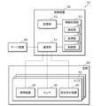
- FIG. 1 is a block diagram showing the functional configuration of a lighting control system according to an embodiment.
- FIG. 2 is a diagram (plan view) showing a space to which the lighting control system according to the embodiment is applied.
- the lighting device 20 is shown by a broken line circle
- the sensor 30 is shown by a solid line circle.
- the lighting control system 10 is a system that can individually provide a lighting environment to users located in a space 80 within a facility.
- the space 80 is, for example, an indoor space that is not partitioned by walls.
- the space 80 is, for example, a free-address office space.
- the space 80 is divided into a plurality of areas 81 each having seats (chairs 82 and desks 83), for example.
- the broken line (straight line) in FIG. 2 indicates a dividing line.
- the space 80 is divided into a matrix shape when viewed from above, but the method of dividing the space 80 is not particularly limited.
- the lighting control system 10 specifically includes a plurality of lighting devices 20, a plurality of sensors 30, a plurality of setting reception devices 40, and a control device 50.
- the lighting device 20, the sensor 30, and the setting reception device 40 are installed in each of the plurality of areas 81.
- a server device 60 is also illustrated in FIG. 1 .
- the lighting device 20 is installed on the ceiling of the space 80 and illuminates the space 80.
- the light source included in the illumination device 20 is realized by, for example, an LED (Light Emitting Diode) element, but may be realized by other light emitting elements such as a semiconductor laser, an organic EL (Electro-Luminescence), or an inorganic EL. .
- the lighting device 20 is, for example, a downlight, but may also be a base light, a ceiling light, a spotlight, or the like, and the specific aspect of the lighting device 20 is not particularly limited.
- the lighting device 20 can be dimmed and colored, and the brightness and color temperature of the light emitted by the lighting device 20 are controlled by the control device 50.
- the sensor 30 is an illuminance sensor that detects (senses) the illuminance in the area 81 where the sensor 30 is provided.
- the sensor 30 is installed, for example, on a desk 83.
- the sensor 30 transmits detection value information indicating a detection value that is a detection result of illuminance (also referred to as brightness) to the control device 50.
- the sensor 30 may be a sensor that detects the color temperature of light in the area 81.
- the setting reception device 40 is a device that allows a user to manually set a target value for the lighting environment (brightness, color temperature, etc.) of the area 81 where the user is located.
- the setting reception device 40 is, for example, a dedicated remote controller that corresponds to the lighting device 20 on a one-to-one basis.
- the setting reception device 40 transmits target value information indicating the target value set by the user to the control device 50.
- a mobile terminal such as a smartphone owned by the user and on which an application program is installed may be used as the setting reception device 40.
- the control device 50 is a controller that controls the plurality of lighting devices 20 installed in the space 80.
- the control device 50 is realized by, for example, an edge server installed in a facility including the space 80 or a cloud server installed outside the facility.
- the control device 50 includes a communication section 51, an information processing section 52, and a storage section 53.
- the communication unit 51 is a communication module (communication circuit) that allows the control device 50 to communicate with the plurality of lighting devices 20, the plurality of sensors 30, the plurality of setting reception devices 40, and the server device 60.
- the communication performed by the communication unit 51 is, for example, wired communication, but may also be wireless communication.
- the communication standard used for communication is also not particularly limited.
- the information processing unit 52 performs information processing regarding control of the lighting device 20 in the space 80.
- the information processing unit 52 is implemented, for example, by a microcomputer, but may also be implemented by a processor.
- the information processing unit 52 includes a detection unit 54, an acquisition unit 55, and a control unit 56 as functional components.
- the functions of the detection unit 54, the acquisition unit 55, and the control unit 56 are realized, for example, by a microcomputer, a processor, or the like constituting the information processing unit 52 executing a computer program stored in the storage unit 53. Detailed functions of each of the detection unit 54, acquisition unit 55, and control unit 56 will be described later.
- the storage unit 53 is a storage device that stores information necessary for the above information processing, computer programs executed by the information processing unit 52, and the like.
- the storage unit 53 is implemented, for example, by a HDD (Hard Disk Drive), but may also be implemented by a semiconductor memory or the like.
- the server device 60 is a computer that provides setting values for feedforward control (described later) to the control device 50.
- the server device 60 is realized, for example, by an edge server installed in a facility including the space 80 or a cloud server installed outside the facility.
- the server device 60 includes a machine learning model, and can determine (calculate) setting values for feedforward control using the machine learning model.
- the machine learning model here has a broad meaning, and the machine learning performed by the machine learning model includes various algorithms such as deep learning. In other words, there are no particular limitations on the specific algorithm for machine learning.
- the server device 60 will be described as an external server device that is not included in the lighting control system 10, but it may be included in the lighting control system 10. That is, the lighting control system 10 may include the server device 60.
- each of the plurality of areas 81 is provided with the lighting device 20, the sensor 30, and the setting reception device 40 in order to control the lighting environment in the area 81.
- the lighting environment specifically refers to brightness or color temperature, but in the following embodiments, a case where the lighting environment is brightness will be mainly described.
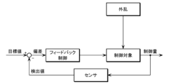
- FIG. 3 is a block diagram showing an overview of feedback control.
- the control device 50 makes the deviation between the detected value of the sensor 30 installed in the target area 81 and the target value zero (the detected value and the target value are equal).
- the setting value is calculated so that the lighting device 20 installed in the target area 81 is controlled based on the calculated setting value.
- the setting value here is the degree of light control (light control rate).
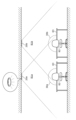
- FIG. 4 is a schematic diagram showing a target area 81 and an area 81 adjacent thereto.
- the target area 81 is described as a target area 81a
- the area 81 adjacent thereto is described as an adjacent area 81b.
- the detection ranges of the sensor 30a and the sensor 30b are illustrated as an image.
- the sensor 30a installed in the target area 81a receives not only the light emitted by the illumination device 20a installed in the target area 81a, but also the light emitted by the illumination device 20b installed in the adjacent area 81b. The emitted light also enters. Similarly, not only the light emitted by the lighting device 20b installed in the adjacent area 81b but also the light emitted by the lighting device 20a installed in the target area 81a enters the sensor 30b installed in the adjacent area 81b.
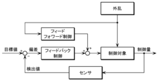
- FIG. 5 is a block diagram showing an overview of control of the lighting environment in the lighting control system 10. As shown in FIG. 5, the control device 50 (control unit 56) performs feedforward control on each of the plurality of lighting devices 20, and the deviation between the target value and detected value of the lighting environment after the feedforward control. Used in conjunction with feedback control to reduce
- the control device 50 acquires the feedforward control settings from the server device 60.
- the server device 60 includes a machine learning model that has learned feedforward control setting values for each of the plurality of lighting devices 20 based on learning data provided in advance from the control device 50 and the like.
- the above learning data includes the following information (a) to information (e).
- Information (a) to (c) is stored (registered) in the storage unit of the control device 50, for example, when the lighting control system 10 is installed.
- the information (d) can be acquired by the acquisition unit 55 from a plurality of sensors 30, for example.
- Information (e) indicates the degree of dimming at which the plurality of lighting devices 20 are currently emitting light, and this information is stored in the storage unit 53.
- the server device 60 detects each of the plurality of sensors 30 when the plurality of lighting devices 20 emits light according to the set value (information (e)). value can be learned. Specifically, the server device 60 (machine learning model) can output feedforward control setting values for each of the plurality of lighting devices 20.
- the detected value at the sensor 30 differs depending on the distance to the sensor 30 and the angle of incidence on the sensor 30.
- the brightness at the position of the sensor 30 is inversely proportional to the square of the distance from the lighting device 20 (light source).
- the brightness at the position of the sensor 30 is cos ⁇ times the brightness when the light arrives from the vertical direction, where ⁇ is the incident angle of the light with respect to the vertical direction.
- Information (b) and (c) are used to learn the correlation between the setting value of the lighting device 20 and the positional relationship between the lighting device 20 and the sensor 30.
- information (a) is specifically the coordinates of the plurality of lighting devices 20 and the plurality of sensors 30 in the space 80. Then, information (b) and (c) can also be calculated from information (a), and in this case, information (b) and (c) may be omitted. Information (a) to (c) can be rephrased as information indicating the positional relationship between the plurality of lighting devices 20 and the plurality of sensors 30.
- the learning data may include all of the information (a) to (e), and some of them may be omitted as necessary. Furthermore, the learning data may include information other than information (a) to (e).
- the lighting device 20 is task lighting (local lighting), and the ambient lighting (overall lighting) that illuminates the entire space 80 (the entire multiple areas 81) apart from the lighting device 20 Lighting) may be installed.
- the learning data may include information indicating the light emission state (setting value, etc.) of the ambient lighting.
- the learning data may include weather information at the point where the space 80 (the plurality of areas 81) is located. Specifically, the weather information is information on the amount of solar radiation related to external light that enters the space 80 from the outside. When the learning data includes this information, the data included in the request information described below also includes this information.
- the learning data may be data in a transient state (a state in which the brightness in each of the plurality of areas 81 has not converged and the target value and the detected value are different), or data in a steady state (in a state in which the brightness in each of the plurality of areas 81 is different).
- the data may be data in a state in which the brightness in each of the states has converged and the target value and the detected value are equal.
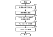
- FIG. 6 is a flowchart of example 1 of controlling the lighting environment of the lighting control system 10.
- the detection unit 54 of the control device 50 detects a change in the target brightness value in at least one of the plurality of areas 81 ( S11).
- the target value is changed, for example, by a user's manual operation on the setting reception device 40. Note that it is not essential that the target value be changed by the user; for example, the target value may be automatically changed based on predetermined schedule information.
- the acquisition unit 55 Upon detection of a change in the target value, the acquisition unit 55 transmits request information for requesting a feedforward control setting value to the server device 60 (S12). Specifically, the acquisition unit 55 uses the communication unit 51 to transmit the request information to the server device 60.
- the request information includes data, and in addition to the above-mentioned information (a) to (e), this data includes (f) a target value of the lighting environment (brightness) in each of the plurality of areas 81. This data can be said to be data related to the plurality of lighting devices 20 and the plurality of sensors 30. Note that the values of information (d) to (f) included in the request information are the latest values at the time when a change in the target value is detected.
- the server device 60 uses the data included in the request information and the machine learning model to compensate for the difference between the target value and the detected value in each of the plurality of areas 81. It is possible to calculate the feedforward control setting value (light control level) of The server device 60 transmits the calculated feedforward control setting values for each of the plurality of lighting devices 20 to the control device 50.
- the communication unit 51 of the control device 50 receives feedforward control setting values for each of the plurality of lighting devices 20 as a response to the request information.
- the acquisition unit 55 acquires the feedforward control setting values of each of the plurality of lighting devices 20 received by the communication unit 51 (S13).
- the feedforward control setting value is an example of control information for reducing the difference between the target value and the detected value in each of the plurality of areas 81.
- control unit 56 performs feedforward control on each of the plurality of lighting devices 20 using the acquired feedforward control settings (S14). Further, the control unit 56 performs feedback control based on the deviation between the target brightness value and the detected value in each of the plurality of areas 81 (S15). Specifically, the control unit 56 calculates a setting value for feedback control based on the deviation between the target brightness value and the detected value, and performs feedback control on each of the plurality of lighting devices 20 using the calculated setting value. I do.
- the lighting control system 10 updates the feedforward control setting value for each of the plurality of lighting devices 20 in response to a change in the target value of brightness in at least one of the plurality of areas 81. , performs feedback control for each of the plurality of lighting devices 20. Thereby, the occurrence of hunting and the like can be suppressed, and the brightness of each of the plurality of areas 81 can be brought close to the target value with high accuracy.
- server device 60 may use data included in the request information as learning data. That is, the server device 60 can update the machine learning model while providing the feedforward control setting value to the control device 50.
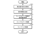
- FIG. 7 is a flowchart of a second example of controlling the lighting environment of the lighting control system 10.
- the detection unit 54 of the control device 50 detects a change in the detected value in at least one of the plurality of areas 81 (S21). Changes in the detected value occur due to, for example, external light entering the space 80.
- the acquisition unit 55 Upon detecting a change in the detection value, the acquisition unit 55 transmits request information for requesting a feedforward control setting value to the server device 60 (S22). Specifically, the acquisition unit 55 uses the communication unit 51 to transmit the request information to the server device 60.
- the request information includes data, and this data includes the information (a) to (f) described above. Note that the values of information (d) to (f) included in the request information are the latest values at the time when a change in the detection value is detected.
- the server device 60 uses the data included in the request information and the machine learning model to compensate for the difference between the target value and the detected value in each of the plurality of areas 81. It is possible to calculate the feedforward control setting value (light control level) of The server device 60 transmits the calculated feedforward control setting values for each of the plurality of lighting devices 20 to the control device 50.
- the communication unit 51 of the control device 50 receives feedforward control setting values for each of the plurality of lighting devices 20 as a response to the request information.
- the acquisition unit 55 acquires feedforward control setting values for each of the plurality of lighting devices 20 (S23). Specifically, the acquisition unit 55 uses the communication unit 51 to acquire (receive) feedforward control setting values for each of the plurality of lighting devices 20 from the server device 60 .
- the feedforward control setting value is an example of control information.
- control unit 56 performs feedforward control on each of the plurality of lighting devices 20 using the acquired feedforward control settings (S24). Further, the control unit 56 performs feedback control based on the deviation between the target brightness value and the detected value in each of the plurality of areas 81 (S25). Specifically, the control unit 56 calculates a setting value for feedback control based on the deviation between the target brightness value and the detected value, and performs feedback control on each of the plurality of lighting devices 20 using the calculated setting value. I do.
- the lighting control system 10 adjusts feedforward control settings for each of the plurality of lighting devices 20 upon a change in the detected brightness value in at least one of the plurality of areas 81 (the plurality of sensors 30). After updating, feedback control is performed for each of the plurality of lighting devices 20. Thereby, the occurrence of hunting and the like can be suppressed, and the brightness of each of the plurality of areas 81 can be brought close to the target value with high accuracy.
- server device 60 may use data included in the request information as learning data. That is, the server device 60 can update the machine learning model while providing the feedforward control setting value to the control device 50.
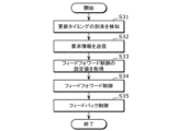
- FIG. 8 is a flowchart of a third example of controlling the lighting environment of the lighting control system 10.
- the feedforward control setting value is periodically updated at update timings that occur at predetermined time intervals.
- the detection unit 54 of the control device 50 detects that the update timing has arrived (S31). Note that the predetermined time interval is appropriately determined empirically or experimentally.
- the acquisition unit 55 transmits request information for requesting the feedforward control setting value to the server device 60 (S32). Specifically, the acquisition unit 55 uses the communication unit 51 to transmit the request information to the server device 60.
- the request information includes data, and this data includes the information (a) to (f) described above. Note that the values of information (d) to (f) included in the request information are the latest values at the time when the arrival of the update timing is detected.
- the server device 60 uses the data included in the request information and the machine learning model to compensate for the difference between the target value and the detected value in each of the plurality of areas 81. It is possible to calculate the feedforward control setting value (light control level) of The server device 60 transmits the calculated feedforward control setting values for each of the plurality of lighting devices 20 to the control device 50.
- the communication unit 51 of the control device 50 receives feedforward control setting values for each of the plurality of lighting devices 20 as a response to the request information.
- the acquisition unit 55 acquires feedforward control setting values for each of the plurality of lighting devices 20 (S33). Specifically, the acquisition unit 55 uses the communication unit 51 to acquire (receive) feedforward control setting values for each of the plurality of lighting devices 20 from the server device 60 .
- the feedforward control setting value is an example of control information.
- control unit 56 performs feedforward control on each of the plurality of lighting devices 20 using the acquired feedforward control settings (S34). Further, the control unit 56 performs feedback control based on the deviation between the target brightness value and the detected value in each of the plurality of areas 81 (S35). Specifically, the control unit 56 calculates a setting value for feedback control based on the deviation between the target brightness value and the detected value, and performs feedback control on each of the plurality of lighting devices 20 using the calculated setting value. I do.
- the lighting control system 10 updates the feedforward control setting values for each of the plurality of lighting devices 20 upon arrival of the update timing, and then performs feedback control for each of the plurality of lighting devices 20. conduct. Thereby, the occurrence of hunting and the like can be suppressed, and the brightness of each of the plurality of areas 81 can be brought close to the target value with high accuracy.
- server device 60 may use data included in the request information as learning data. That is, the server device 60 can update the machine learning model while providing the feedforward control setting value to the control device 50.
- the lighting control system 10 may operate in a learning mode to provide learning data to the server device 60.
- the learning mode operation is an operation for generating learning data.
- the lighting control system 10 operates as follows, for example.
- the control unit 56 of the control device 50 selects one of the plurality of lighting devices 20 as a target lighting device.
- the control unit 56 causes the target lighting device to emit light at a first setting value (for example, dimming intensity 50%), and causes the non-target lighting devices (all lighting devices 20 other than the target lighting device) to emit light at a second setting. Light is emitted at a certain value (for example, dimming level 20%).
- the control unit 56 generates learning data (data including the above information (a) to (e)).
- the control unit 56 repeats the above operation by changing the target lighting device. When all of the plurality of lighting devices 20 are selected once as target lighting devices, the learning mode operation ends. Note that the control unit 56 may further repeat the operation in the learning mode by changing at least one of the first set value and the second set value. Learning data generated during operation in the learning mode is provided from the control device 50 to the server device 60 as appropriate.
- the lighting control system 10 aims to expand the variation of learning data by acquiring the detection values of each of the plurality of sensors 30 when the setting values of each of the plurality of lighting devices 20 are forcibly changed. I can do it.
- the order in which the plurality of lighting devices 20 are selected as target lighting devices is not particularly limited.
- the lighting device 20 in the center may be selected as the target lighting device first, or the lighting devices 20 located at the corners may be It may be selected as the target lighting device first.
- the server device 60 uses not only learning data based on the lighting conditions in the space 80 but also learning data based on the lighting conditions in other spaces to learn the setting values for feedforward control.
- the server device 60 uses the same Learning data based on the lighting conditions on the second floor (another space) within the facility may be collected.
- the second floor is a different floor from the first floor.
- the server device 60 may collect learning data based on lighting conditions on three or more floors.
- the server device 60 can improve the accuracy of calculating the feedforward control setting value by collecting learning data based on the lighting conditions on two or more floors within the same facility.
- the server device 60 stores the learning data based on the lighting state within the first facility (space 80). Learning data based on the lighting conditions within the two facilities (other spaces) may also be collected.
- the second facility is a facility different from the first facility.
- the server device 60 may collect learning data based on lighting conditions at three or more facilities.
- the server device 60 can improve the calculation accuracy of the feedforward control setting value by collecting learning data based on the lighting conditions in each of the spaces in two or more facilities.
- the lighting control system 10 can be applied to control a lighting environment including at least one of brightness, color temperature, light distribution, and the like.
- the arrangement of the plurality of lighting devices 20 and the arrangement of the plurality of sensors 30 in the above embodiment are merely examples.
- the plurality of lighting devices 20 may be arranged in any manner as long as they can individually illuminate the plurality of adjacent areas 81.
- the plurality of sensors 30 may be arranged in any manner as long as they can individually sense the detected values of the lighting environment in the plurality of areas 81.
- the target value of the lighting environment in each of the plurality of areas 81 is set (changed) by the user located in the space 80, but it is not essential that the target value is set by the user.
- the target value may be set by an administrator located outside the space. Further, the target value may be automatically changed based on predetermined schedule information.
- the lighting control system 10 includes a plurality of lighting devices 20 for individually illuminating a plurality of adjacent areas 81, each of which has a set target value for its lighting environment; By transmitting data related to the plurality of sensors 30 for individually sensing the detection values of the lighting environment in the plurality of areas 81 to the server device 60, the difference between the target value and the detection value in each of the plurality of areas 81 can be calculated. It includes an acquisition unit 55 that acquires control information for reduction from the server device 60, and a control unit 56 that controls the plurality of lighting devices 20 using the acquired control information.
- Such a lighting control system 10 can bring the lighting environment of the plurality of areas 81, where changes in the lighting environment mutually influence each other, closer to the target.
- control unit 56 uses both feedforward control and feedback control for each of the plurality of lighting devices 20, and the control information includes a set value of the feedforward control for each of the plurality of lighting devices 20. This is the information shown.
- the lighting control system 10 In such a lighting control system 10, most of the control is performed by feedforward control, and the remaining slight deviation between the target value and the detected value can be reduced by feedback control.
- the lighting control system 10 can suppress the occurrence of hunting and the like.
- the data includes information indicating the positional relationship between the plurality of lighting devices 20 and the plurality of sensors 30.
- Such a lighting control system 10 can acquire control information that takes into account the positional relationships between the plurality of lighting devices 20 and the plurality of sensors 30. In other words, the lighting control system 10 can control the plurality of lighting devices 20 in consideration of the positional relationship between the plurality of lighting devices 20 and the plurality of sensors 30.
- the information indicating the positional relationship includes information indicating the distance between each of the plurality of lighting devices 20 and each of the plurality of sensors 30, and the incidence of light emitted by each of the plurality of lighting devices 20 on each of the plurality of sensors 30. Contains information indicating corners.
- Such a lighting control system 10 can acquire control information that takes into account the distance and the angle of incidence. In other words, the lighting control system 10 can control the plurality of lighting devices 20 in consideration of the distance and the angle of incidence.
- the acquisition unit 55 acquires control information from the server device 60 by transmitting data to the server device 60 when the target value of the lighting environment in at least one of the plurality of areas 81 is changed. do.
- Such a lighting control system 10 can acquire (update) control information in response to a change in the target value of the lighting environment.
- the acquisition unit 55 acquires control information from the server device 60 by transmitting data to the server device 60 when the detected value of the lighting environment in at least one of the plurality of areas 81 changes. .
- Such a lighting control system 10 can acquire (update) control information in response to a change in the detected value of the lighting environment.
- the acquisition unit 55 acquires control information from the server device 60 by transmitting data to the server device 60 at predetermined time intervals.
- Such a lighting control system 10 can acquire (update) control information at predetermined time intervals.
- the data includes at least one of information indicating the light emission state of the overall illumination that illuminates the entire plurality of areas 81 and weather information at the points where the plurality of areas 81 are located.
- Such a lighting control system 10 can acquire control information that takes into consideration at least one of the light emission state of the overall lighting and weather information.
- the lighting control system 10 can control the plurality of lighting devices 20 in consideration of at least one of the light emission state of the overall lighting and weather information.
- the server device 60 includes a machine learning model that outputs control information based on the received data.
- the lighting control system 10 controls only a target lighting device among the plurality of lighting devices 20 to emit light at a setting value that is different from other lighting devices. Learning data is generated by repeating the process while changing the target lighting device.
- Such a lighting control system 10 can increase the variation of learning data.
- the plurality of areas 81 are provided on the first floor within the facility.
- the server device 60 collects learning data based on the lighting condition on the second floor in the facility in addition to learning data based on the lighting condition on the first floor.
- Such a server device 60 can improve the accuracy of control information by collecting learning data based on lighting conditions on multiple floors within the same facility.
- the server device 60 collects learning data based on the lighting condition in the second facility in addition to learning data based on the lighting condition in the first facility.
- Such a server device 60 can improve the accuracy of control information by collecting learning data based on the lighting conditions in each of the spaces within a plurality of facilities.
- the lighting control method executed by a computer such as the lighting control system 10 includes a plurality of areas 81 for each of which a target value of the lighting environment is determined, and a plurality of areas 81 for individually illuminating a plurality of adjacent areas 81. target values in each of the plurality of areas 81 by transmitting data related to the lighting device 20 and the plurality of sensors 30 for individually sensing detected values of the lighting environment in the plurality of areas 81 to the server device 60. and a control step of controlling the plurality of lighting devices 20 using the acquired control information.
- Such a lighting control method can bring the lighting environment of the plurality of areas 81, where changes in the lighting environment mutually influence each other, closer to the target.
- the lighting control system was realized by a plurality of devices.
- the components (particularly functional components) included in the lighting control system may be distributed to the plurality of devices in any manner.
- the lighting control system may also be implemented as a single device.
- the lighting control system may be implemented as a single device corresponding to the control device.
- the order of processing described in the above embodiment is an example.
- the order of multiple processes may be changed, and multiple processes may be executed in parallel.
- the processing executed by a specific processing unit may be executed by another processing unit.
- each component may be realized by executing a software program suitable for each component.
- Each component may be realized by a program execution unit such as a CPU or a processor reading and executing a software program recorded on a recording medium such as a hard disk or a semiconductor memory.
- each component may be realized by hardware.
- each component may be a circuit (or integrated circuit). These circuits may constitute one circuit as a whole, or may be separate circuits. Further, each of these circuits may be a general-purpose circuit or a dedicated circuit.
- the general or specific aspects of the present invention may be implemented in a system, device, method, integrated circuit, computer program, or computer-readable recording medium such as a CD-ROM.
- the present invention may be realized by any combination of a system, an apparatus, a method, an integrated circuit, a computer program, and a recording medium.
- the present invention may be implemented as a lighting control method executed by a computer such as a lighting control system, or may be implemented as a program for causing a computer to execute such a lighting control method.
- the present invention may be realized as a computer-readable non-transitory recording medium on which such a program is recorded.
Landscapes
- Circuit Arrangement For Electric Light Sources In General (AREA)
Abstract
照明制御システム(10)は、各々に照明環境の目標値が定められた複数のエリア(81)であって隣接する複数のエリア(81)を個別に照明するための複数の照明装置(20)と、複数のエリア(81)における照明環境の検出値を個別にセンシングするための複数のセンサ(30)とに関連するデータをサーバ装置(60)へ送信することにより、複数のエリア(81)それぞれにおける目標値及び検出値の差を低減するための制御情報をサーバ装置(60)から取得する取得部(55)と、取得された制御情報を用いて複数の照明装置(20)を制御する制御部(56)とを備える。
Description
本発明は、照明制御システム、及び、照明制御方法に関する。
室内空間における照明環境を制御するための技術が知られている。特許文献1には、点灯途中のLEDの色彩を、既に点灯しているLEDの色彩に連動して変化させる追従機能を備えたLED照明装置が開示されている。
本発明は、照明環境の変化が相互に影響する複数のエリアの照明環境を目標に近づけることができる照明制御システム等を提供する。
本発明の一態様に係る照明制御システムは、各々に照明環境の目標値が定められた複数のエリアであって隣接する前記複数のエリアを個別に照明するための複数の照明装置と、前記複数のエリアにおける照明環境の検出値を個別にセンシングするための複数のセンサとに関連するデータを外部サーバ装置へ送信することにより、前記複数のエリアそれぞれにおける前記目標値及び前記検出値の差を低減するための制御情報を前記外部サーバ装置から取得する取得部と、取得された前記制御情報を用いて前記複数の照明装置を制御する制御部とを備える。
本発明の一態様に係る照明制御方法は、コンピュータによって実行される照明制御方法であって、各々に照明環境の目標値が定められた複数のエリアであって隣接する前記複数のエリアを個別に照明するための複数の照明装置と、前記複数のエリアにおける照明環境の検出値を個別にセンシングするための複数のセンサとに関連するデータを外部サーバ装置へ送信することにより、前記複数のエリアそれぞれにおける前記目標値及び前記検出値の差を低減するための制御情報を前記外部サーバ装置から取得する取得ステップと、取得された前記制御情報を用いて前記複数の照明装置を制御する制御ステップとを含む。
本発明の一態様に係る照明制御システム等は、照明環境の変化が相互に影響する複数のエリアの照明環境を目標に近づけることができる。
以下、実施の形態について、図面を参照しながら具体的に説明する。なお、以下で説明する実施の形態は、いずれも包括的又は具体的な例を示すものである。以下の実施の形態で示される数値、形状、材料、構成要素、構成要素の配置位置及び接続形態、ステップ、ステップの順序などは、一例であり、本発明を限定する主旨ではない。また、以下の実施の形態における構成要素のうち、独立請求項に記載されていない構成要素については、任意の構成要素として説明される。
なお、各図は模式図であり、必ずしも厳密に図示されたものではない。また、各図において、実質的に同一の構成に対しては同一の符号を付し、重複する説明は省略又は簡略化される場合がある。
(実施の形態)
[構成]
まず、実施の形態に係る照明制御システムの構成について説明する。図1は、実施の形態に係る照明制御システムの機能構成を示すブロック図である。図2は、実施の形態に係る照明制御システムが適用される空間を示す図(平面図)である。なお、図2では、照明装置20が破線の円で示され、センサ30が実線の円で示されている。
[構成]
まず、実施の形態に係る照明制御システムの構成について説明する。図1は、実施の形態に係る照明制御システムの機能構成を示すブロック図である。図2は、実施の形態に係る照明制御システムが適用される空間を示す図(平面図)である。なお、図2では、照明装置20が破線の円で示され、センサ30が実線の円で示されている。
照明制御システム10は、施設内の空間80に位置するユーザに、個別に照明環境を提供することができるシステムである。空間80は、例えば、壁で仕切られていない室内空間である。空間80は、例えば、フリーアドレス方式のオフィス空間などである。図2に示されるように、空間80は、例えば、各々に座席(椅子82及び机83)が設置された複数のエリア81に分割される。図2における破線(直線)は、分割線を示す。空間80は、例えば、上面視においてマトリクス状に分割されるが、空間80の分割方法については特に限定されない。
図1に示されるように、照明制御システム10は、具体的には、複数の照明装置20と、複数のセンサ30と、複数の設定受付装置40と、制御装置50とを備える。照明装置20、センサ30、及び、設定受付装置40は、複数のエリア81のそれぞれに設置されている。また、図1には、サーバ装置60も図示されている。
照明装置20は、空間80の天井に設置され空間80を照らす。照明装置20が備える光源は、例えば、LED(Light Emitting Diode)素子によって実現されるが、半導体レーザ、有機EL(Electro-Luminescence)、または、無機EL等の他の発光素子によって実現されてもよい。照明装置20は、例えば、ダウンライトであるが、ベースライト、シーリングライト、または、スポットライトなどであってもよく、照明装置20の具体的態様については特に限定されない。照明装置20は、調光及び調色が可能であり、照明装置20が発する光の明るさ及び色温度は、制御装置50によって制御される。
センサ30は、センサ30が設けられたエリア81における照度を検出(センシング)する照度センサである。センサ30は、例えば、机83の上などに設置される。センサ30は、照度(明るさとも記載される)の検出結果である検出値を示す検出値情報を制御装置50へ送信する。センサ30は、エリア81における光の色温度を検出するセンサであってもよい。
設定受付装置40は、ユーザが、当該ユーザが位置するエリア81の照明環境(明るさまたは色温度など)の目標値を手動操作によって設定するための機器である。設定受付装置40は、例えば、照明装置20と1対1で対応する専用のリモートコントローラである。設定受付装置40は、ユーザによって設定された目標値を示す目標値情報を制御装置50へ送信する。なお、専用のリモートコントローラに代えて、ユーザが所持するスマートフォンなどの携帯端末であってアプリケーションプログラムがインストールされた携帯端末が設定受付装置40として使用されてもよい。
制御装置50は、空間80に設置される複数の照明装置20を制御するコントローラである。制御装置50は、例えば、空間80を含む施設に設置されたエッジサーバ、または、当該施設外に設置されたクラウドサーバなどによって実現される。制御装置50は、具体的には、通信部51と、情報処理部52と、記憶部53とを備える。
通信部51は、制御装置50が、複数の照明装置20、複数のセンサ30、複数の設定受付装置40、及び、サーバ装置60と通信を行うための通信モジュール(通信回路)である。通信部51によって行われる通信は、例えば、有線通信であるが、無線通信であってもよい。通信に用いられる通信規格についても特に限定されない。
情報処理部52は、空間80における照明装置20の制御に関する情報処理を行う。情報処理部52は、例えば、マイクロコンピュータによって実現されるが、プロセッサによって実現されてもよい。
情報処理部52は、機能的な構成要素として、検知部54、取得部55、及び、制御部56を有する。検知部54、取得部55、及び、制御部56の機能は、例えば、情報処理部52を構成するマイクロコンピュータまたはプロセッサ等が記憶部53に記憶されたコンピュータプログラムを実行することによって実現される。検知部54、取得部55、及び、制御部56のそれぞれの詳細な機能については後述する。
記憶部53は、上記情報処理に必要な情報、及び、情報処理部52が実行するコンピュータプログラムなどが記憶される記憶装置である。記憶部53は、例えば、HDD(Hard Disk Drive)によって実現されるが、半導体メモリなどによって実現されてもよい。
サーバ装置60は、フィードフォワード制御(後述)の設定値を制御装置50に提供するコンピュータである。サーバ装置60は、例えば、空間80を含む施設に設置されたエッジサーバ、または、当該施設外に設置されたクラウドサーバなどによって実現される。サーバ装置60は、機械学習モデルを備え、当該機械学習モデルを用いてフィードフォワード制御の設定値を決定(算出)することができる。ここでの機械学習モデルとは広義の意味であり、機械学習モデルによって行われる機械学習には、ディープラーニング(深層学習)等の様々なアルゴリズムが含まれる。つまり、機械学習の具体的アルゴリズムについては特に限定されない。
なお、以下の実施の形態では、サーバ装置60は、照明制御システム10に含まれていない、外部サーバ装置であるとして説明されるが、照明制御システム10に含まれてもよい。つまり、照明制御システム10は、サーバ装置60を備えてもよい。
[フィードバック制御の課題]
上述のように複数のエリア81のそれぞれには、当該エリア81における照明環境を制御するために、照明装置20、センサ30、及び、設定受付装置40が設けられている。照明環境は、具体的には、明るさまたは色温度などを意味するが、以下の実施の形態では主として照明環境が明るさである場合について説明する。
上述のように複数のエリア81のそれぞれには、当該エリア81における照明環境を制御するために、照明装置20、センサ30、及び、設定受付装置40が設けられている。照明環境は、具体的には、明るさまたは色温度などを意味するが、以下の実施の形態では主として照明環境が明るさである場合について説明する。
例えば、複数のエリア81のうち対象のエリア81に設置された設定受付装置40に明るさの目標値が設定されると、制御装置50の制御部56は、対象のエリア81に設置された照明装置20を制御することにより、対象のエリア81において目標値が示す明るさの実現を図る。目標値が示す明るさを実現するための制御手法としては、フィードバック制御が考えられる。図3は、フィードバック制御の概要を示すブロック図である。
図3に示されるように、フィードバック制御においては、制御装置50は、対象のエリア81に設置されたセンサ30の検出値と目標値との偏差が0となる(検出値と目標値とが等しくなる)ように設定値を算出し、対象のエリア81に設置された照明装置20を算出した設定値に基づいて制御する。ここでの設定値は、具体的には、調光度(調光率)である。
ここで、対象のエリア81とこれに隣接するエリア81とは、明るさの変化が相互に影響する。図4は、対象のエリア81とこれに隣接するエリア81とを示す模式図である。図4では、対象のエリア81は、対象のエリア81aと記載され、これに隣接するエリア81は、隣接エリア81bと記載されている。図4では、センサ30a及びセンサ30bについては、その検出範囲がイメージ的に図示されている。
図4に示されるように、対象のエリア81aに設置されたセンサ30aには、対象のエリア81aに設置された照明装置20aが発する光だけでなく、隣接エリア81bに設置された照明装置20bが発する光も入射する。同様に、隣接エリア81bに設置されたセンサ30bには、隣接エリア81bに設置された照明装置20bが発する光だけでなく、対象のエリア81aに設置された照明装置20aが発する光も入射する。
そうすると、対象のエリア81a、及び、隣接エリア81bのそれぞれにおいてフィードバック制御が行われると、ハンチングが発生してしまう可能性がある。また、対象のエリア81a、及び、隣接エリア81bのそれぞれの明るさが収束するまでに長い時間を要する可能性もある。
[照明制御システムにおける照明環境の制御の概要]
そこで、制御装置50は、目標値の変化、及び、外光の入射等の外乱による影響を考慮したフィードフォワード制御によって大部分の制御を行い、オーバーシュートの発生、及び、振動的な応答の発生を抑制する。さらに、制御装置50は、残りのわずかな目標値と検出値との偏差の低減をフィードバック制御によって実現する。図5は、照明制御システム10における照明環境の制御の概要を示すブロック図である。図5に示されるように、制御装置50(制御部56)は、複数の照明装置20のそれぞれに対して、フィードフォワード制御と、当該フィードフォワード制御後の照明環境の目標値及び検出値の偏差を低減するフィードバック制御とを併用する。
そこで、制御装置50は、目標値の変化、及び、外光の入射等の外乱による影響を考慮したフィードフォワード制御によって大部分の制御を行い、オーバーシュートの発生、及び、振動的な応答の発生を抑制する。さらに、制御装置50は、残りのわずかな目標値と検出値との偏差の低減をフィードバック制御によって実現する。図5は、照明制御システム10における照明環境の制御の概要を示すブロック図である。図5に示されるように、制御装置50(制御部56)は、複数の照明装置20のそれぞれに対して、フィードフォワード制御と、当該フィードフォワード制御後の照明環境の目標値及び検出値の偏差を低減するフィードバック制御とを併用する。
制御装置50は、フィードフォワード制御の設定値をサーバ装置60から取得する。サーバ装置60は、あらかじめ制御装置50等から提供される学習データに基づいて、複数の照明装置20のそれぞれに対するフィードフォワード制御の設定値を学習した機械学習モデルを備えている。
ここで、上記の学習データは、以下の情報(a)~情報(e)を含む。
(a)複数の照明装置20及び複数のセンサ30の配置を示す情報
(b)複数の照明装置20のそれぞれと複数のセンサ30それぞれとの距離を示す情報
(c)複数の照明装置20それぞれが発する光の複数のセンサ30のそれぞれに対する入射角を示す情報
(d)複数のセンサ30のそれぞれにおける検出値
(e)複数の照明装置20のそれぞれの設定値
(b)複数の照明装置20のそれぞれと複数のセンサ30それぞれとの距離を示す情報
(c)複数の照明装置20それぞれが発する光の複数のセンサ30のそれぞれに対する入射角を示す情報
(d)複数のセンサ30のそれぞれにおける検出値
(e)複数の照明装置20のそれぞれの設定値
情報(a)~(c)については、例えば、照明制御システム10の導入時に制御装置50の記憶部に記憶(登録)される。情報(d)については、例えば、取得部55が複数のセンサ30から取得することができる。情報(e)については、複数の照明装置20が現在どのような調光度で発光しているかを意味しており、これについては記憶部53に記憶されている。
このような学習データによれば、サーバ装置60(機械学習モデル)は、複数の照明装置20が設定値(情報(e))にしたがって発光しているときの、複数のセンサ30のそれぞれの検出値を学習することができる。サーバ装置60(機械学習モデル)は、具体的には、複数の照明装置20それぞれのフィードフォワード制御の設定値を出力することができる。
ここで、学習データに情報(b)及び(c)が含まれる理由について補足する。照明装置20の設定値(調光度)が同一であっても、センサ30までの距離、及び、センサ30への入射角によってセンサ30における検出値は異なる。例えば、センサ30の位置における明るさは、照明装置20(光源)からの距離の2乗に反比例する。センサ30の位置における明るさは、鉛直方向に対する光の入射角をθとして、光が鉛直方向から到来する場合の明るさのcosθ倍となる。情報(b)及び(c)は、照明装置20の設定値と照明装置20及びセンサ30の位置関係との相関性を学習させるために用いられる。
なお、情報(a)は、具体的には、空間80における複数の照明装置20及び複数のセンサ30の座標である。そうすると、情報(a)から情報(b)及び(c)を算出することもでき、この場合、情報(b)及び(c)は省略されてもよい。情報(a)~(c)は、複数の照明装置20及び複数のセンサ30の位置関係を示す情報と言い換えることができる。
また、学習データが情報(a)~(e)の全てを含むことは必須ではなく、必要に応じて一部が省略されてもよい。また、学習データは、情報(a)~(e)以外の情報を含んでもよい。
例えば、空間80においてタスクアンビエント照明が採用されており、照明装置20がタスク照明(局所照明)であり、照明装置20とは別に空間80全体(複数のエリア81全体)を照明するアンビエント照明(全体照明)が設置されている場合が考えられる。このような場合、学習データには、アンビエント照明の発光状態(設定値など)を示す情報が含まれてもよい。また、学習データには、空間80(複数のエリア81)が位置する地点における気象情報が含まれてもよい。気象情報は、具体的には、空間80に外部から差し込む外光に関連する、日射量の情報などである。学習データにこれらの情報が含まれる場合、後述の要求情報に含まれるデータにもこれらの情報が含まれる。
なお、学習データは、過渡状態(複数のエリア81のそれぞれにおける明るさが収束しておらず、目標値と検出値が異なる状態)におけるデータであってもよいし、定常状態(複数のエリア81のそれぞれにおける明るさが収束しており、目標値と検出値が等しい状態)におけるデータであってもよい。
[照明環境の制御例1]
次に、照明制御システム10の照明環境の制御について、より具体的に説明する。図6は、照明制御システム10の照明環境の制御例1のフローチャートである。
次に、照明制御システム10の照明環境の制御について、より具体的に説明する。図6は、照明制御システム10の照明環境の制御例1のフローチャートである。
定常状態(複数のエリア81のそれぞれにおける明るさが収束している状態)において、制御装置50の検知部54は、複数のエリア81の少なくとも1つにおける明るさの目標値の変更を検知する(S11)。目標値の変更は、例えば、ユーザの設定受付装置40への手動操作によって行われる。なお、目標値がユーザによって変更されることは必須ではなく、例えば、目標値が予め定められたスケジュール情報によって自動的に変更されるような場合もある。
取得部55は、目標値の変更が検知されたことを契機に、フィードフォワード制御の設定値を要求するための要求情報をサーバ装置60へ送信する(S12)。取得部55は、具体的には、通信部51を用いて要求情報をサーバ装置60へ送信する。要求情報にはデータが含まれ、このデータは、上述の情報(a)~(e)に加えて、(f)複数のエリア81それぞれにおける照明環境(明るさ)の目標値、を含む。このデータは、複数の照明装置20、及び、複数のセンサ30に関連するデータであるといえる。なお、要求情報に含まれる情報(d)~(f)の値は、目標値の変更が検知された時点における、最新の値である。
ここで、サーバ装置60は、上記要求情報を受信すると、要求情報に含まれる上記データと機械学習モデルとを用いて、複数のエリア81のそれぞれにおける目標値と検出値との差分を補償するためのフィードフォワード制御の設定値(調光度)を算出することができる。サーバ装置60は、算出した複数の照明装置20それぞれのフィードフォワード制御の設定値を制御装置50へ送信する。
制御装置50の通信部51は、上記要求情報への応答として、複数の照明装置20それぞれのフィードフォワード制御の設定値を受信する。取得部55は、通信部51によって受信された複数の照明装置20それぞれのフィードフォワード制御の設定値を取得する(S13)。フィードフォワード制御の設定値は、複数のエリア81それぞれにおける目標値及び検出値の差を低減するための制御情報の一例である。
次に、制御部56は、取得されたフィードフォワード制御の設定値を用いて複数の照明装置20それぞれに対してフィードフォワード制御を行う(S14)。また、制御部56は、複数のエリア81のそれぞれにおいて、明るさの目標値及び検出値の偏差に基づくフィードバック制御を行う(S15)。制御部56は、具体的には、明るさの目標値及び検出値の偏差に基づいてフィードバック制御の設定値を算出し、算出した設定値を用いて複数の照明装置20それぞれに対してフィードバック制御を行う。
このように、照明制御システム10は、複数のエリア81の少なくとも1つにおける明るさの目標値が変更されたことを契機に複数の照明装置20それぞれに対するフィードフォワード制御の設定値を更新した上で、複数の照明装置20それぞれに対してフィードバック制御を行う。これにより、ハンチングの発生等を抑制して、高い精度で複数のエリア81それぞれの明るさを目標値に近づけることができる。
なお、サーバ装置60は、要求情報に含まれるデータを学習データとして使用してもよい。つまり、サーバ装置60は、フィードフォワード制御の設定値を制御装置50へ提供しつつ、機械学習モデルを更新することができる。
[照明環境の制御例2]
次に、照明制御システム10の照明環境の制御例2について説明する。図7は、照明制御システム10の照明環境の制御例2のフローチャートである。
次に、照明制御システム10の照明環境の制御例2について説明する。図7は、照明制御システム10の照明環境の制御例2のフローチャートである。
定常状態において、制御装置50の検知部54は、複数のエリア81の少なくとも1つにおける検出値の変化を検出する(S21)。検出値の変化は、例えば、空間80に外光が差し込むことなどによって発生する。
取得部55は、検出値の変化が検知されたことを契機に、フィードフォワード制御の設定値を要求するための要求情報をサーバ装置60へ送信する(S22)。取得部55は、具体的には、通信部51を用いて要求情報をサーバ装置60へ送信する。要求情報にはデータが含まれ、このデータは、上述の情報(a)~(f)を含む。なお、要求情報に含まれる情報(d)~(f)の値は、検出値の変化が検知された時点における、最新の値である。
ここで、サーバ装置60は、上記要求情報を受信すると、要求情報に含まれる上記データと機械学習モデルとを用いて、複数のエリア81のそれぞれにおける目標値と検出値との差分を補償するためのフィードフォワード制御の設定値(調光度)を算出することができる。サーバ装置60は、算出した複数の照明装置20それぞれのフィードフォワード制御の設定値を制御装置50へ送信する。
制御装置50の通信部51は、上記要求情報への応答として、複数の照明装置20それぞれのフィードフォワード制御の設定値を受信する。取得部55は、複数の照明装置20それぞれのフィードフォワード制御の設定値を取得する(S23)。取得部55は、具体的には、通信部51を用いて複数の照明装置20それぞれのフィードフォワード制御の設定値をサーバ装置60から取得(受信)する。フィードフォワード制御の設定値は、制御情報の一例である。
次に、制御部56は、取得されたフィードフォワード制御の設定値を用いて複数の照明装置20それぞれに対してフィードフォワード制御を行う(S24)。また、制御部56は、複数のエリア81のそれぞれにおいて、明るさの目標値及び検出値の偏差に基づくフィードバック制御を行う(S25)。制御部56は、具体的には、明るさの目標値及び検出値の偏差に基づいてフィードバック制御の設定値を算出し、算出した設定値を用いて複数の照明装置20それぞれに対してフィードバック制御を行う。
このように、照明制御システム10は、複数のエリア81(複数のセンサ30)の少なくとも1つにおける明るさの検出値が変化したことを契機に複数の照明装置20それぞれに対するフィードフォワード制御の設定値を更新した上で、複数の照明装置20それぞれに対してフィードバック制御を行う。これにより、ハンチングの発生等を抑制して、高い精度で複数のエリア81それぞれの明るさを目標値に近づけることができる。
なお、サーバ装置60は、要求情報に含まれるデータを学習データとして使用してもよい。つまり、サーバ装置60は、フィードフォワード制御の設定値を制御装置50へ提供しつつ、機械学習モデルを更新することができる。
[照明環境の制御例3]
次に、照明制御システム10の照明環境の制御例3について説明する。図8は、照明制御システム10の照明環境の制御例3のフローチャートである。
次に、照明制御システム10の照明環境の制御例3について説明する。図8は、照明制御システム10の照明環境の制御例3のフローチャートである。
制御例3では、フィードフォワード制御の設定値は、所定の時間間隔で訪れる更新タイミングにおいて定期的に更新される。制御装置50の検知部54は、更新タイミングが到来したことを検知する(S31)。なお、所定の時間間隔は、経験的または実験的に適宜定められる。
取得部55は、更新タイミングの到来が検知されたことを契機に、フィードフォワード制御の設定値を要求するための要求情報をサーバ装置60へ送信する(S32)。取得部55は、具体的には、通信部51を用いて要求情報をサーバ装置60へ送信する。要求情報にはデータが含まれ、このデータは、上述の情報(a)~(f)を含む。なお、要求情報に含まれる情報(d)~(f)の値は、更新タイミングの到来が検知された時点における、最新の値である。
ここで、サーバ装置60は、上記要求情報を受信すると、要求情報に含まれる上記データと機械学習モデルとを用いて、複数のエリア81のそれぞれにおける目標値と検出値との差分を補償するためのフィードフォワード制御の設定値(調光度)を算出することができる。サーバ装置60は、算出した複数の照明装置20それぞれのフィードフォワード制御の設定値を制御装置50へ送信する。
制御装置50の通信部51は、上記要求情報への応答として、複数の照明装置20それぞれのフィードフォワード制御の設定値を受信する。取得部55は、複数の照明装置20それぞれのフィードフォワード制御の設定値を取得する(S33)。取得部55は、具体的には、通信部51を用いて複数の照明装置20それぞれのフィードフォワード制御の設定値をサーバ装置60から取得(受信)する。フィードフォワード制御の設定値は、制御情報の一例である。
次に、制御部56は、取得されたフィードフォワード制御の設定値を用いて複数の照明装置20それぞれに対してフィードフォワード制御を行う(S34)。また、制御部56は、複数のエリア81のそれぞれにおいて、明るさの目標値及び検出値の偏差に基づくフィードバック制御を行う(S35)。制御部56は、具体的には、明るさの目標値及び検出値の偏差に基づいてフィードバック制御の設定値を算出し、算出した設定値を用いて複数の照明装置20それぞれに対してフィードバック制御を行う。
このように、照明制御システム10は、更新タイミングが到来したことを契機に複数の照明装置20それぞれに対するフィードフォワード制御の設定値を更新した上で、複数の照明装置20それぞれに対してフィードバック制御を行う。これにより、ハンチングの発生等を抑制して、高い精度で複数のエリア81それぞれの明るさを目標値に近づけることができる。
なお、サーバ装置60は、要求情報に含まれるデータを学習データとして使用してもよい。つまり、サーバ装置60は、フィードフォワード制御の設定値を制御装置50へ提供しつつ、機械学習モデルを更新することができる。
[学習モードの動作]
また、照明制御システム10は、学習データをサーバ装置60へ提供するための学習モードの動作を行ってもよい。学習モードの動作は、言い換えれば、学習データを生成するための動作である。学習モードにおいて、照明制御システム10は、例えば、以下のように動作する。
また、照明制御システム10は、学習データをサーバ装置60へ提供するための学習モードの動作を行ってもよい。学習モードの動作は、言い換えれば、学習データを生成するための動作である。学習モードにおいて、照明制御システム10は、例えば、以下のように動作する。
制御装置50の制御部56は、複数の照明装置20のうちの1つを対象の照明装置として選択する。制御部56は、対象の照明装置を第1の設定値(例えば、調光度50%)で発光させ、非対象の照明装置(対象の照明装置以外の全ての照明装置20)を第2の設定値(例えば、調光度20%)で発光させる。この状態で制御部56は、学習データ(上記情報(a)~(e)を含むデータ)を生成する。
制御部56は、以上の動作を、対象の照明装置を変更して繰り返す。複数の照明装置20の全てが1回ずつ対象の照明装置として選択されると、学習モードの動作は終了となる。なお、制御部56は、第1の設定値及び第2の設定値の少なくとも一方を変更して、学習モードの動作をさらに繰り返してもよい。学習モードの動作中に生成された学習データは、適宜、制御装置50からサーバ装置60へ提供される。
このように、照明制御システム10は、複数の照明装置20それぞれの設定値を強制的に変更したときの複数のセンサ30それぞれの検出値を取得することによって、学習データのバリエーションの拡充を図ることができる。
なお、学習モードの動作において、複数の照明装置20が対象の照明装置として選択される順序については特に限定されない。複数の照明装置20が図2に示されるようにマトリクス状に配置されているときには、中央の照明装置20が最初に対象の照明装置として選択されてもよいし、角に位置する照明装置20が最初に対象の照明装置として選択されてもよい。
ところで、サーバ装置60(機械学習モデル)は、空間80における照明状態に基づく学習データだけでなく、他の空間における照明状態に基づく学習データをさらに用いて、フィードフォワード制御の設定値を学習してもよい。例えば、空間80(複数のエリア81)が施設内の第1フロアに設けられている場合に、サーバ装置60は、第1フロア(空間80)における照明状態に基づく学習データに加えて、同一の施設内の第2フロア(他の空間)における照明状態に基づく学習データを収集してもよい。第2フロアは、第1フロアと異なるフロアである。サーバ装置60は、3つ以上のフロアにおける照明状態に基づく学習データを収集してもよい。
このように、サーバ装置60は、同一施設内の2以上のフロアにおける照明状態に基づく学習データを収集することで、フィードフォワード制御の設定値の算出精度の向上を図ることができる。
また、例えば、空間80(複数のエリア81)が第1施設内に設けられている場合に、サーバ装置60は、第1施設内(空間80)における照明状態に基づく学習データに加えて、第2施設内(他の空間)の照明状態に基づく学習データを収集してもよい。第2施設は、第1施設と異なる施設である。サーバ装置60は、3つ以上の施設における照明状態に基づく学習データを収集してもよい。
このように、サーバ装置60は、2以上の施設内の空間それぞれにおける照明状態に基づく学習データを収集することで、フィードフォワード制御の設定値の算出精度の向上を図ることができる。
[変形例]
上記実施の形態では、複数のエリア81それぞれの明るさが制御される例について説明したが、明るさに代えて色温度または配光などが制御されてもよい。照明制御システム10は、明るさ、色温度、及び、配光などの少なくとも1つを含む照明環境の制御に適用することができる。
上記実施の形態では、複数のエリア81それぞれの明るさが制御される例について説明したが、明るさに代えて色温度または配光などが制御されてもよい。照明制御システム10は、明るさ、色温度、及び、配光などの少なくとも1つを含む照明環境の制御に適用することができる。
また、上記実施の形態における複数の照明装置20の配置、複数のセンサ30の配置は一例である。複数の照明装置20は、隣接する複数のエリア81を個別に照明することができれば、どのように配置されていてもよい。また、複数のセンサ30は、複数のエリア81における照明環境の検出値を個別にセンシングすることができれば、どのように配置されていてもよい。
また、上記実施の形態では、複数のエリア81それぞれにおける照明環境の目標値は、空間80内に位置するユーザによって設定(変更)されたが、目標値がユーザによって設定されることは必須ではない。例えば、目標値は、空間外に位置する管理者等によって設定されてもよい。また、目標値は、予め定められたスケジュール情報によって自動的に変更されてもよい。
[効果等]
以上説明したように、照明制御システム10は、各々に照明環境の目標値が定められた複数のエリア81であって隣接する複数のエリア81を個別に照明するための複数の照明装置20と、複数のエリア81における照明環境の検出値を個別にセンシングするための複数のセンサ30とに関連するデータをサーバ装置60へ送信することにより、複数のエリア81それぞれにおける目標値及び検出値の差を低減するための制御情報をサーバ装置60から取得する取得部55と、取得された制御情報を用いて複数の照明装置20を制御する制御部56とを備える。
以上説明したように、照明制御システム10は、各々に照明環境の目標値が定められた複数のエリア81であって隣接する複数のエリア81を個別に照明するための複数の照明装置20と、複数のエリア81における照明環境の検出値を個別にセンシングするための複数のセンサ30とに関連するデータをサーバ装置60へ送信することにより、複数のエリア81それぞれにおける目標値及び検出値の差を低減するための制御情報をサーバ装置60から取得する取得部55と、取得された制御情報を用いて複数の照明装置20を制御する制御部56とを備える。
このような照明制御システム10は、照明環境の変化が相互に影響する複数のエリア81の照明環境を、目標に近づけることができる。
また、例えば、制御部56は、複数の照明装置20のそれぞれに対して、フィードフォワード制御と、フィードバック制御とを併用し、制御情報は、複数の照明装置20それぞれに対するフィードフォワード制御の設定値を示す情報である。
このような照明制御システム10は、フィードフォワード制御によって大部分の制御を行い、残りのわずかな目標値と検出値との偏差の低減をフィードバック制御によって実現することができる。照明制御システム10は、ハンチングの発生等の抑制を図ることができる。
また、例えば、上記データには、複数の照明装置20及び複数のセンサ30の位置関係を示す情報が含まれる。
このような照明制御システム10は、複数の照明装置20及び複数のセンサ30の位置関係を考慮した制御情報を取得することができる。言い換えれば、照明制御システム10は、複数の照明装置20及び複数のセンサ30の位置関係を考慮して複数の照明装置20を制御することができる。
また、例えば、位置関係を示す情報には、複数の照明装置20それぞれと複数のセンサ30それぞれとの距離を示す情報、及び、複数の照明装置20それぞれが発する光の複数のセンサ30それぞれに対する入射角を示す情報が含まれる。
このような照明制御システム10は、上記距離及び上記入射角を考慮した制御情報を取得することができる。言い換えれば、照明制御システム10は、上記距離及び上記入射角を考慮して複数の照明装置20を制御することができる。
また、例えば、取得部55は、複数のエリア81の少なくとも1つにおける照明環境の目標値が変更されたことを契機にデータをサーバ装置60へ送信することにより、制御情報をサーバ装置60から取得する。
このような照明制御システム10は、照明環境の目標値が変更されたことを契機に制御情報を取得(更新)することができる。
また、例えば、取得部55は、複数のエリア81の少なくとも1つにおける照明環境の検出値が変化したことを契機にデータをサーバ装置60へ送信することにより、制御情報をサーバ装置60から取得する。
このような照明制御システム10は、照明環境の検出値が変更されたことを契機に制御情報を取得(更新)することができる。
また、例えば、取得部55は、所定の時間間隔でデータをサーバ装置60へ送信することにより、制御情報をサーバ装置60から取得する。
このような照明制御システム10は、所定の時間間隔で制御情報を取得(更新)することができる。
また、例えば、データには、複数のエリア81全体を照明する全体照明の発光状態を示す情報、及び、複数のエリア81が位置する地点における気象情報の少なくとも一方が含まれる。
このような照明制御システム10は、全体照明の発光状態、及び、気象情報の少なくとも一方を考慮した制御情報を取得することができる。言い換えれば、照明制御システム10は、全体照明の発光状態、及び、気象情報の少なくとも一方を考慮して複数の照明装置20を制御することができる。
また、例えば、サーバ装置60は、受信した前記データに基づいて制御情報を出力する機械学習モデルを備える。照明制御システム10は、機械学習モデルへ学習データを提供するための学習モードの動作において、複数の照明装置20のうち対象の照明装置だけを他の照明装置と異なる設定値で発光させる制御を、対象の照明装置を変更しながら繰り返すことで、学習データを生成する。
このような照明制御システム10は、学習データのバリエーションの増大を図ることができる。
また、例えば、複数のエリア81は、施設内の第1フロアに設けられる。サーバ装置60は、第1フロアにおける照明状態に基づく学習データに加えて、上記施設内の第2フロアにおける照明状態に基づく学習データを収集する。
このようなサーバ装置60は、同一施設内の複数のフロアにおける照明状態に基づく学習データを収集することで、制御情報の精度の向上を図ることができる。
また、例えば、複数のエリア81は、第1施設内に設けられる。サーバ装置60は、第1施設内における照明状態に基づく学習データに加えて、第2施設内の照明状態に基づく学習データを収集する。
このようなサーバ装置60は、複数の施設内の空間それぞれにおける照明状態に基づく学習データを収集することで、制御情報の精度の向上を図ることができる。
また、照明制御システム10などのコンピュータによって実行される照明制御方法は、各々に照明環境の目標値が定められた複数のエリア81であって隣接する複数のエリア81を個別に照明するための複数の照明装置20と、複数のエリア81における照明環境の検出値を個別にセンシングするための複数のセンサ30とに関連するデータをサーバ装置60へ送信することにより、複数のエリア81それぞれにおける目標値及び検出値の差を低減するための制御情報をサーバ装置60から取得する取得ステップと、取得された制御情報を用いて複数の照明装置20を制御する制御ステップとを含む。
このような照明制御方法は、照明環境の変化が相互に影響する複数のエリア81の照明環境を、目標に近づけることができる。
(その他の実施の形態)
以上、実施の形態について説明したが、本発明は、上記実施の形態に限定されるものではない。
以上、実施の形態について説明したが、本発明は、上記実施の形態に限定されるものではない。
例えば、上記実施の形態において、照明制御システムは、複数の装置によって実現された。この場合、照明制御システムが備える構成要素(特に、機能的な構成要素)は、複数の装置にどのように振り分けられてもよい。また、照明制御システムは、単一の装置として実現されてもよい。例えば、照明制御システムは、制御装置に相当する単一の装置として実現されてもよい。
また、上記実施の形態で説明された処理の順序は、一例である。複数の処理の順序は変更されてもよいし、複数の処理は並行して実行されてもよい。また、特定の処理部が実行する処理を別の処理部が実行してもよい。
また、上記実施の形態において、各構成要素は、各構成要素に適したソフトウェアプログラムを実行することによって実現されてもよい。各構成要素は、CPU又はプロセッサなどのプログラム実行部が、ハードディスク又は半導体メモリなどの記録媒体に記録されたソフトウェアプログラムを読み出して実行することによって実現されてもよい。
また、各構成要素は、ハードウェアによって実現されてもよい。例えば、各構成要素は、回路(又は集積回路)でもよい。これらの回路は、全体として1つの回路を構成してもよいし、それぞれ別々の回路でもよい。また、これらの回路は、それぞれ、汎用的な回路でもよいし、専用の回路でもよい。
また、本発明の全般的又は具体的な態様は、システム、装置、方法、集積回路、コンピュータプログラム又はコンピュータ読み取り可能なCD-ROMなどの記録媒体で実現されてもよい。また、システム、装置、方法、集積回路、コンピュータプログラム及び記録媒体の任意な組み合わせで実現されてもよい。例えば、本発明は、照明制御システムなどのコンピュータが実行する照明制御方法として実行されてもよいし、このような照明制御方法をコンピュータに実行させるためのプログラムとして実現されてもよい。また、本発明は、このようなプログラムが記録されたコンピュータ読み取り可能な非一時的な記録媒体として実現されてもよい。
その他、各実施の形態に対して当業者が思いつく各種変形を施して得られる形態、又は、本発明の趣旨を逸脱しない範囲で各実施の形態における構成要素及び機能を任意に組み合わせることで実現される形態も本発明に含まれる。
10 照明制御システム
20、20a、20b 照明装置
30、30a、30b センサ
40 設定受付装置
50 制御装置
51 通信部
52 情報処理部
53 記憶部
54 検知部
55 取得部
56 制御部
60 サーバ装置(外部サーバ装置)
80 空間
81 エリア
81a 対象のエリア
81b 隣接エリア
82 椅子
83 机
20、20a、20b 照明装置
30、30a、30b センサ
40 設定受付装置
50 制御装置
51 通信部
52 情報処理部
53 記憶部
54 検知部
55 取得部
56 制御部
60 サーバ装置(外部サーバ装置)
80 空間
81 エリア
81a 対象のエリア
81b 隣接エリア
82 椅子
83 机
Claims (12)
- 各々に照明環境の目標値が定められた複数のエリアであって隣接する前記複数のエリアを個別に照明するための複数の照明装置と、前記複数のエリアにおける照明環境の検出値を個別にセンシングするための複数のセンサとに関連するデータを外部サーバ装置へ送信することにより、前記複数のエリアそれぞれにおける前記目標値及び前記検出値の差を低減するための制御情報を前記外部サーバ装置から取得する取得部と、
取得された前記制御情報を用いて前記複数の照明装置を制御する制御部とを備える
照明制御システム。 - 前記制御部は、前記複数の照明装置のそれぞれに対して、フィードフォワード制御と、フィードバック制御とを併用し、
前記制御情報は、前記複数の照明装置それぞれに対する前記フィードフォワード制御の設定値を示す情報である
請求項1に記載の照明制御システム。 - 前記データには、前記複数の照明装置及び前記複数のセンサの位置関係を示す情報が含まれる
請求項1に記載の照明制御システム。 - 前記位置関係を示す情報には、前記複数の照明装置それぞれと前記複数のセンサそれぞれとの距離を示す情報、及び、前記複数の照明装置それぞれが発する光の前記複数のセンサそれぞれに対する入射角を示す情報が含まれる
請求項3に記載の照明制御システム。 - 前記取得部は、前記複数のエリアの少なくとも1つにおける前記目標値が変更されたことを契機に前記データを前記外部サーバ装置へ送信することにより、前記制御情報を前記外部サーバ装置から取得する
請求項1~4のいずれか1項に記載の照明制御システム。 - 前記取得部は、前記複数のエリアの少なくとも1つにおける前記検出値が変化したことを契機に前記データを前記外部サーバ装置へ送信することにより、前記制御情報を前記外部サーバ装置から取得する
請求項1~4のいずれか1項に記載の照明制御システム。 - 前記取得部は、所定の時間間隔で前記データを前記外部サーバ装置へ送信することにより、前記制御情報を前記外部サーバ装置から取得する
請求項1~4のいずれか1項に記載の照明制御システム。 - 前記データには、前記複数のエリア全体を照明する全体照明の発光状態を示す情報、及び、前記複数のエリアが位置する地点における気象情報の少なくとも一方が含まれる
請求項1~4のいずれか1項に記載の照明制御システム。 - 前記外部サーバ装置は、受信した前記データに基づいて前記制御情報を出力する機械学習モデルを備え、
前記照明制御システムは、前記機械学習モデルへ学習データを提供するための学習モードの動作において、前記複数の照明装置のうち対象の照明装置だけを他の照明装置と異なる設定値で発光させる制御を、前記対象の照明装置を変更しながら繰り返すことで、学習データを生成する
請求項1~4のいずれか1項に記載の照明制御システム。 - 前記複数のエリアは、施設内の第1フロアに設けられ、
前記外部サーバ装置は、前記第1フロアにおける照明状態に基づく学習データに加えて、前記施設内の第2フロアにおける照明状態に基づく学習データを収集する
請求項9に記載の照明制御システム。 - 前記複数のエリアは、第1施設内に設けられ、
前記外部サーバ装置は、前記第1施設内における照明状態に基づく学習データに加えて、第2施設内の照明状態に基づく学習データを収集する
請求項9に記載の照明制御システム。 - コンピュータによって実行される照明制御方法であって、
各々に照明環境の目標値が定められた複数のエリアであって隣接する前記複数のエリアを個別に照明するための複数の照明装置と、前記複数のエリアにおける照明環境の検出値を個別にセンシングするための複数のセンサとに関連するデータを外部サーバ装置へ送信することにより、前記複数のエリアそれぞれにおける前記目標値及び前記検出値の差を低減するための制御情報を前記外部サーバ装置から取得する取得ステップと、
取得された前記制御情報を用いて前記複数の照明装置を制御する制御ステップとを含む
照明制御方法。
Applications Claiming Priority (2)
| Application Number | Priority Date | Filing Date | Title |
|---|---|---|---|
| JP2022065839 | 2022-04-12 | ||
| JP2022-065839 | 2022-04-12 |
Publications (1)
| Publication Number | Publication Date |
|---|---|
| WO2023199669A1 true WO2023199669A1 (ja) | 2023-10-19 |
Family
ID=88329392
Family Applications (1)
| Application Number | Title | Priority Date | Filing Date |
|---|---|---|---|
| PCT/JP2023/009275 WO2023199669A1 (ja) | 2022-04-12 | 2023-03-10 | 照明制御システム、及び、照明制御方法 |
Country Status (1)
| Country | Link |
|---|---|
| WO (1) | WO2023199669A1 (ja) |
Citations (2)
| Publication number | Priority date | Publication date | Assignee | Title |
|---|---|---|---|---|
| JP2001015270A (ja) * | 1999-06-30 | 2001-01-19 | Matsushita Electric Works Ltd | 調光制御システム |
| JP2020053359A (ja) * | 2018-09-28 | 2020-04-02 | 東芝ライテック株式会社 | 情報処理システム |
-
2023
- 2023-03-10 WO PCT/JP2023/009275 patent/WO2023199669A1/ja unknown
Patent Citations (2)
| Publication number | Priority date | Publication date | Assignee | Title |
|---|---|---|---|---|
| JP2001015270A (ja) * | 1999-06-30 | 2001-01-19 | Matsushita Electric Works Ltd | 調光制御システム |
| JP2020053359A (ja) * | 2018-09-28 | 2020-04-02 | 東芝ライテック株式会社 | 情報処理システム |
Similar Documents
| Publication | Publication Date | Title |
|---|---|---|
| US10349496B2 (en) | Lighting control system and lighting control device used therefor | |
| US10111275B2 (en) | Scheduling failover for lighting controls | |
| JP5777716B2 (ja) | 照明調光率決定装置 | |
| KR20110118693A (ko) | 주변 조명 조건들에 반응하는 조명 제어 시스템 | |
| RU2013148930A (ru) | Устройство и способ управления освещенностью от множества источников света | |
| US20160234913A1 (en) | Lighting system and method for controlling lighting system | |
| JP6839103B2 (ja) | 照明システム内の装置を設定するための方法 | |
| JP6704193B2 (ja) | 照明制御装置 | |
| JP2016149214A (ja) | 照明システムおよび照明システムの制御方法 | |
| WO2023199669A1 (ja) | 照明制御システム、及び、照明制御方法 | |
| JP2013004311A (ja) | 照明制御システム | |
| JP2012186078A (ja) | 照明制御システム | |
| US10757789B2 (en) | System and method to group light sensors for controlling illumination uniformly based on ambient light | |
| KR20140140275A (ko) | 최적화 알고리즘을 이용한 감성조명 시스템, 감성조명 제어장치 및 방법 | |
| KR20140117057A (ko) | 엘이디 조명 제어 장치 | |
| JP7183570B2 (ja) | 照明制御システム | |
| KR101292123B1 (ko) | 배광 정보를 갖는 스마트 조명 장치 및 이를 이용한 조명 제어 시스템 | |
| KR101846495B1 (ko) | 에너지 절감을 위한 무선네트워크 기반 led 조명 제어 및 운영 방법 | |
| JP2007184181A (ja) | 照明制御システム | |
| JP6917922B2 (ja) | 照明制御システム、照明器具、照明制御方法及びコンピュータプログラム | |
| KR20120128385A (ko) | 고 에너지효율 조명 시스템 및 그 제어방법 | |
| Thompson et al. | Investigation of tunable LED lighting for general illumination employing preliminary activity recognition sensor network | |
| TWM455811U (zh) | 具可調之節能時控表的燈組及燈控系統 | |
| JP2015041569A (ja) | 照明制御装置、照明制御方法、及びプログラム | |
| WO2015093148A1 (ja) | 照明システム及び制御装置 |
Legal Events
| Date | Code | Title | Description |
|---|---|---|---|
| 121 | Ep: the epo has been informed by wipo that ep was designated in this application |
Ref document number: 23788091 Country of ref document: EP Kind code of ref document: A1 |