WO2023190834A1 - 超音波ユニット、回折膨潤テープ、及び超音波集束装置 - Google Patents
超音波ユニット、回折膨潤テープ、及び超音波集束装置 Download PDFInfo
- Publication number
- WO2023190834A1 WO2023190834A1 PCT/JP2023/013107 JP2023013107W WO2023190834A1 WO 2023190834 A1 WO2023190834 A1 WO 2023190834A1 JP 2023013107 W JP2023013107 W JP 2023013107W WO 2023190834 A1 WO2023190834 A1 WO 2023190834A1
- Authority
- WO
- WIPO (PCT)
- Prior art keywords
- ultrasonic
- gel
- fzp
- ultrasound
- piezoelectric element
- Prior art date
- Legal status (The legal status is an assumption and is not a legal conclusion. Google has not performed a legal analysis and makes no representation as to the accuracy of the status listed.)
- Ceased
Links
Images


















Classifications
-
- B—PERFORMING OPERATIONS; TRANSPORTING
- B06—GENERATING OR TRANSMITTING MECHANICAL VIBRATIONS IN GENERAL
- B06B—METHODS OR APPARATUS FOR GENERATING OR TRANSMITTING MECHANICAL VIBRATIONS OF INFRASONIC, SONIC, OR ULTRASONIC FREQUENCY, e.g. FOR PERFORMING MECHANICAL WORK IN GENERAL
- B06B1/00—Methods or apparatus for generating mechanical vibrations of infrasonic, sonic, or ultrasonic frequency
- B06B1/02—Methods or apparatus for generating mechanical vibrations of infrasonic, sonic, or ultrasonic frequency making use of electrical energy
- B06B1/06—Methods or apparatus for generating mechanical vibrations of infrasonic, sonic, or ultrasonic frequency making use of electrical energy operating with piezoelectric effect or with electrostriction
- B06B1/0607—Methods or apparatus for generating mechanical vibrations of infrasonic, sonic, or ultrasonic frequency making use of electrical energy operating with piezoelectric effect or with electrostriction using multiple elements
- B06B1/0622—Methods or apparatus for generating mechanical vibrations of infrasonic, sonic, or ultrasonic frequency making use of electrical energy operating with piezoelectric effect or with electrostriction using multiple elements on one surface
-
- A—HUMAN NECESSITIES
- A61—MEDICAL OR VETERINARY SCIENCE; HYGIENE
- A61B—DIAGNOSIS; SURGERY; IDENTIFICATION
- A61B17/00—Surgical instruments, devices or methods
-
- A—HUMAN NECESSITIES
- A61—MEDICAL OR VETERINARY SCIENCE; HYGIENE
- A61N—ELECTROTHERAPY; MAGNETOTHERAPY; RADIATION THERAPY; ULTRASOUND THERAPY
- A61N7/00—Ultrasound therapy
-
- B—PERFORMING OPERATIONS; TRANSPORTING
- B06—GENERATING OR TRANSMITTING MECHANICAL VIBRATIONS IN GENERAL
- B06B—METHODS OR APPARATUS FOR GENERATING OR TRANSMITTING MECHANICAL VIBRATIONS OF INFRASONIC, SONIC, OR ULTRASONIC FREQUENCY, e.g. FOR PERFORMING MECHANICAL WORK IN GENERAL
- B06B1/00—Methods or apparatus for generating mechanical vibrations of infrasonic, sonic, or ultrasonic frequency
- B06B1/02—Methods or apparatus for generating mechanical vibrations of infrasonic, sonic, or ultrasonic frequency making use of electrical energy
- B06B1/0207—Driving circuits
- B06B1/0223—Driving circuits for generating signals continuous in time
- B06B1/0238—Driving circuits for generating signals continuous in time of a single frequency, e.g. a sine-wave
-
- B—PERFORMING OPERATIONS; TRANSPORTING
- B06—GENERATING OR TRANSMITTING MECHANICAL VIBRATIONS IN GENERAL
- B06B—METHODS OR APPARATUS FOR GENERATING OR TRANSMITTING MECHANICAL VIBRATIONS OF INFRASONIC, SONIC, OR ULTRASONIC FREQUENCY, e.g. FOR PERFORMING MECHANICAL WORK IN GENERAL
- B06B3/00—Methods or apparatus specially adapted for transmitting mechanical vibrations of infrasonic, sonic, or ultrasonic frequency
- B06B3/04—Methods or apparatus specially adapted for transmitting mechanical vibrations of infrasonic, sonic, or ultrasonic frequency involving focusing or reflecting
-
- G—PHYSICS
- G10—MUSICAL INSTRUMENTS; ACOUSTICS
- G10K—SOUND-PRODUCING DEVICES; METHODS OR DEVICES FOR PROTECTING AGAINST, OR FOR DAMPING, NOISE OR OTHER ACOUSTIC WAVES IN GENERAL; ACOUSTICS NOT OTHERWISE PROVIDED FOR
- G10K11/00—Methods or devices for transmitting, conducting or directing sound in general; Methods or devices for protecting against, or for damping, noise or other acoustic waves in general
- G10K11/18—Methods or devices for transmitting, conducting or directing sound
- G10K11/26—Sound-focusing or directing, e.g. scanning
- G10K11/28—Sound-focusing or directing, e.g. scanning using reflection, e.g. parabolic reflectors
-
- G—PHYSICS
- G10—MUSICAL INSTRUMENTS; ACOUSTICS
- G10K—SOUND-PRODUCING DEVICES; METHODS OR DEVICES FOR PROTECTING AGAINST, OR FOR DAMPING, NOISE OR OTHER ACOUSTIC WAVES IN GENERAL; ACOUSTICS NOT OTHERWISE PROVIDED FOR
- G10K11/00—Methods or devices for transmitting, conducting or directing sound in general; Methods or devices for protecting against, or for damping, noise or other acoustic waves in general
- G10K11/18—Methods or devices for transmitting, conducting or directing sound
- G10K11/26—Sound-focusing or directing, e.g. scanning
- G10K11/30—Sound-focusing or directing, e.g. scanning using refraction, e.g. acoustic lenses
-
- H—ELECTRICITY
- H04—ELECTRIC COMMUNICATION TECHNIQUE
- H04R—LOUDSPEAKERS, MICROPHONES, GRAMOPHONE PICK-UPS OR LIKE ACOUSTIC ELECTROMECHANICAL TRANSDUCERS; ELECTRIC HEARING AIDS; PUBLIC ADDRESS SYSTEMS
- H04R1/00—Details of transducers, loudspeakers or microphones
- H04R1/20—Arrangements for obtaining desired frequency or directional characteristics
- H04R1/32—Arrangements for obtaining desired frequency or directional characteristics for obtaining desired directional characteristic only
- H04R1/34—Arrangements for obtaining desired frequency or directional characteristics for obtaining desired directional characteristic only by using a single transducer with sound reflecting, diffracting, directing or guiding means
-
- H—ELECTRICITY
- H04—ELECTRIC COMMUNICATION TECHNIQUE
- H04R—LOUDSPEAKERS, MICROPHONES, GRAMOPHONE PICK-UPS OR LIKE ACOUSTIC ELECTROMECHANICAL TRANSDUCERS; ELECTRIC HEARING AIDS; PUBLIC ADDRESS SYSTEMS
- H04R17/00—Piezoelectric transducers; Electrostrictive transducers
Definitions
- the present invention relates to an ultrasound unit, a diffractive swelling tape, and an ultrasound focusing device.
- a focused sound wave therapy device that includes a planar element that generates ultrasonic waves and an acoustic lens that allows the ultrasonic waves to pass through.
- sound waves are generated with a sound wave transmitting gel and an acoustic lens interposed between the planar element and the skin surface. This allows the energy of the sound waves to be focused on the treatment site located at a desired depth from the skin surface.
- the acoustic lens has a concave portion located on the opposite side to the surface attached to the planar element.
- the concave portion has a spherical surface designed based on a curvature that corresponds to the focal distance from the skin to the treatment site.
- the focal length can be adjusted by adjusting the curvature of the concave portion.
- the present invention has been made in view of the above-mentioned problems, and provides an ultrasonic unit, a diffractive swelling tape, and an ultrasonic focusing device that have a structure that is easy to process and can reduce processing costs.
- the purpose is to
- An ultrasonic unit includes a piezoelectric element having an ultrasonic generation surface that generates ultrasonic waves, and a piezoelectric element located on the ultrasonic generation surface or located apart from the ultrasonic generation surface.
- a transmission type diffraction section includes a piezoelectric element having an ultrasonic generation surface that generates ultrasonic waves, and a piezoelectric element located on the ultrasonic generation surface or located apart from the ultrasonic generation surface.
- the transmission type diffraction section may be located on the ultrasound generation surface, and the transmission type diffraction section may be a different member from the piezoelectric element.
- the ultrasonic unit according to one aspect of the present invention may include a swelling body provided on the ultrasonic generation surface so as to cover the transmission type diffraction section.
- the transmission type diffraction section is located apart from the ultrasound generation surface, and the transmission type diffraction section is spaced apart from and facing the ultrasound generation surface.
- a first surface and a second surface opposite to the first surface a swelling body is disposed at least between the ultrasonic generation surface and the first surface, and the swelling body Alternatively, at least the transmission type diffraction section may be adhered to the piezoelectric element.
- the swelling body may adhere the transmission type diffraction section to the piezoelectric element so as to cover both the first surface and the second surface.
- the swelling body is located between the ultrasonic generation surface and the first surface, and the swelling body is a first swelling body that makes the transmission type diffraction part adhere to the piezoelectric element. and a second swelling body that is attachable to and detachable from the second surface.
- the swelling body has a contact surface that contacts the ultrasonic generation surface and a surface opposite to the contact surface that is exposed to the outside of the ultrasonic unit.
- the swelling body located between the first surface and the contact surface has a first thickness in the direction from the contact surface to the exposed surface;
- the swelling body located between the exposed surface and the exposed surface has a second thickness, and by adjusting at least one of the first thickness and the second thickness, from the exposed surface to the focal point.
- the focal length or the focusing rate of the ultrasound waves may be adjusted.
- the swelling body has a contact surface that contacts the ultrasonic generation surface and a surface opposite to the contact surface that is exposed to the outside of the ultrasonic unit.
- the transmission type diffraction section has a slit, and by adjusting the width of the slit, the focal length from the exposed surface to the focal point or the focusing rate of the ultrasound can be adjusted. Good too.
- the transmission type diffraction section includes a first member, a second member that is spaced apart from the first member and surrounds the first member, and a second member that is spaced apart from the first member and surrounds the first member;
- the connecting portion may be located between the first member and the second member and connect the first member and the second member.
- the diffraction swelling tape according to one embodiment of the present invention is used in the ultrasonic unit according to the above-mentioned embodiment.
- This diffraction swelling tape includes a transmission type diffraction portion having a first surface and a second surface opposite to the first surface, and a piezoelectric element that covers at least one of the first surface and the second surface. and a swelling body that is adhered to.
- An ultrasonic focusing device includes an ultrasonic unit, a signal generating section that supplies a frequency signal to the ultrasonic unit, and an AC voltage generating section that supplies an alternating current voltage to the signal generating section.
- the ultrasonic unit includes a piezoelectric element having an ultrasonic generation surface that generates ultrasonic waves, and a transmission type diffraction section located on the ultrasonic generation surface or located apart from the ultrasonic generation surface. and.
- processing costs can be reduced by having a structure that is easy to process.
- FIG. 1 is a functional block diagram showing an example of the configuration of an ultrasonic focusing device according to a first embodiment of the present invention.
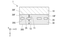
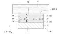
- 1 is a schematic cross-sectional view partially showing the structure of an ultrasound unit according to a first embodiment of the present invention, as viewed from a direction parallel to the ultrasound unit.
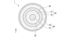
- FIG. 1 is a schematic cross-sectional view partially showing the structure of an ultrasound unit according to a first embodiment of the present invention, as viewed from the thickness direction of the ultrasound unit.
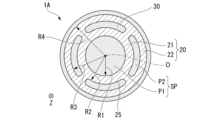
- FIG. FIG. 3 is a schematic sectional view partially showing a modification of the FZP member constituting the ultrasound unit according to the first embodiment of the present invention, as viewed from the thickness direction of the ultrasound unit.
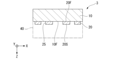
- FIG. 2 is a schematic cross-sectional view partially showing the structure of an ultrasound unit according to a second embodiment of the present invention, as viewed from a direction parallel to the ultrasound unit.
- FIG. 7 is a schematic cross-sectional view partially showing the structure of an ultrasound unit according to a third embodiment of the present invention, as viewed from a direction parallel to the ultrasound unit.
- FIG. 7 is a schematic cross-sectional view partially showing the structure of an ultrasound unit according to a fourth embodiment of the present invention, as viewed from a direction parallel to the ultrasound unit.
- FIG. 7 is a schematic cross-sectional view partially showing the structure of an ultrasound unit according to a fifth embodiment of the present invention, as viewed from a direction parallel to the ultrasound unit.
- FIG. 7 is a schematic cross-sectional view partially showing the structure of a diffractive gel tape according to a sixth embodiment of the present invention, as viewed from a direction parallel to the diffractive gel tape. It is a top view which partially shows the modification of the diffractive gel tape based on 6th Embodiment of this invention.
- FIG. 7 is a schematic cross-sectional view partially showing the structure of a diffractive gel tape according to a modification of the seventh embodiment of the present invention, as viewed from a direction parallel to the diffractive gel tape.
- FIG. 7 is a schematic cross-sectional view partially showing the structure of a diffractive gel tape according to a seventh embodiment of the present invention, and is a diagram for explaining a method for manufacturing the diffractive gel tape.
- FIG. 7 is a schematic cross-sectional view partially showing the structure of a diffractive gel tape according to a sixth embodiment of the present invention, as viewed from a direction parallel to the diffractive gel tape. It is a top view which
- FIG. 7 is a schematic cross-sectional view partially showing the structure of a diffractive gel tape according to a seventh embodiment of the present invention, and is a diagram for explaining a method for manufacturing the diffractive gel tape.
- FIG. 7 is a schematic cross-sectional view partially showing the structure of a diffractive gel tape according to a modification of the seventh embodiment of the present invention, and is a diagram for explaining a method for manufacturing the diffractive gel tape.
- FIG. 7 is a schematic cross-sectional view partially showing the structure of a diffractive gel tape according to a modification of the seventh embodiment of the present invention, and is a diagram for explaining a method for manufacturing the diffractive gel tape.
- FIG. 7 is a schematic cross-sectional view partially showing the structure of a diffractive gel tape according to a modification of the seventh embodiment of the present invention, and is a diagram for explaining a method for manufacturing the diffractive gel tape.
- FIG. 7 is a schematic cross-sectional view partially showing the structure of a diffractive gel tape according to a modification of the seventh embodiment of the present invention, and is a diagram for explaining a method for manufacturing the diffractive gel tape.
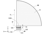
- FIG. 2 is a cross-sectional view schematically showing an ultrasound unit according to an example of the present invention, and is a diagram for explaining simulation conditions.
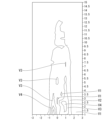
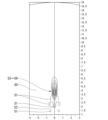
- FIG. 2 is a cross-sectional view schematically showing an ultrasound unit according to Example 1 of the present invention, and is a diagram for explaining a simulation analysis model. It is a figure showing the result of simulation of the ultrasonic unit concerning Example 1 of the present invention. It is a figure showing the result of simulation of the ultrasonic unit concerning Example 1 of the present invention.
- FIG. 3 is a cross-sectional view schematically showing an ultrasound unit of a comparative example, and is a diagram for explaining simulation conditions.
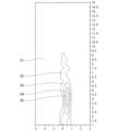
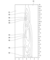
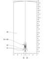
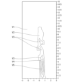
- FIG. 2 is a cross-sectional view schematically showing an ultrasound unit of a comparative example, and is a diagram for explaining a simulation analysis model. It is a figure which shows the result of the simulation of the ultrasonic unit of a comparative example. It is a figure which shows the result of the simulation of the ultrasonic unit of a comparative example. It is a figure which shows the result of the simulation of the ultrasonic unit based on Example 2 of this invention.
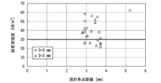
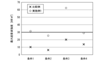
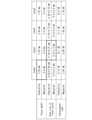
- FIG. 7 is a diagram showing the results of comparing the present invention and a comparative example regarding maximum ultrasonic intensity in Example 3 of the present invention. It is a table showing conditions of Example 4 of the present invention. It is a figure showing the composition of the test device used in Example 4 of the present invention.
- FIG. 6 is a diagram showing simulation results of a comparative example regarding Example 4 of the present invention.
- FIG. 4 is a diagram showing the experimental results of a comparative example using a test device regarding Example 4 of the present invention.
- FIG. 7 is a diagram showing simulation results for lens 1 regarding Example 4 of the present invention.
- FIG. 7 is a diagram showing experimental results of lens 1 using a testing device regarding Example 4 of the present invention.
- FIG. 7 is a diagram showing simulation results for lens 2 regarding Example 4 of the present invention.
- FIG. 7 is a diagram showing experimental results of lens 2 using a testing device regarding Example 4 of the present invention.
- FIG. 6 is a diagram showing simulation results of a comparative example regarding Example 4 of the present invention.
- FIG. 4 is a diagram showing the experimental results of a comparative example using a test device regarding Example 4 of the present invention.
- FIG. 7 is a diagram showing the experimental results of a comparative example using a test device regarding Example 4 of the present invention.
- FIG. 7 is a diagram showing simulation results for lens 3 regarding Example 4 of the present invention.
- FIG. 6 is a diagram showing experimental results of lens 3 using a testing device regarding Example 4 of the present invention.
- FIG. 7 is a diagram showing simulation results of lens 4 regarding Example 4 of the present invention.
- FIG. 4 is a diagram showing experimental results of lens 4 using a testing device regarding Example 4 of the present invention.
- 3 is a table summarizing simulation results and experimental results for lenses 1 to 4 regarding Example 4 of the present invention.
- ordinal numbers such as “first” and “second” may be used. This ordinal number does not indicate the number of members described by the ordinal number. Ordinal numbers may be used to indicate that each of a plurality of members is a separate member.
- the Z direction corresponds to the thickness direction of the ultrasonic unit or the direction from the contact surface to the exposed surface of the gel member.
- the Z direction corresponds to the direction in which the ultrasonic waves generated from the piezoelectric element propagate toward the swelling body.
- the X direction is called the X direction and the other is called the Y direction.
- the X direction and the Y direction may be referred to as a direction parallel to the ultrasound unit or a direction parallel to the diffractive gel tape.
- the direction extending radially from the center of the ultrasound unit is referred to as the radial direction.
- the circumferential direction of the ultrasonic unit having a circular shape when viewed in the Z direction is referred to as the circumferential direction.
- the terms "X direction,” “Y direction,” and “Z direction” are used to explain the mutual positional relationship of the multiple members that make up the ultrasonic unit, and the shape and structure of each of the multiple members. This is a statement and does not define the posture of the ultrasound unit. Depending on the usage state of the ultrasound unit, the attitude of the ultrasound unit can be freely changed. In such a state of use, for example, the ultrasonic unit may be inverted or tilted in at least one of the three directions.
- an ultrasound unit, a diffraction gel tape, and an ultrasound focusing device are applied to, for example, an acupuncture point stimulation device.
- an acupuncture point stimulation device by using the action of ultrasound focusing, it is possible to non-invasively target a treatment area (focal point) located at a desired depth from the skin surface of a living body such as a human body or an animal. It is possible to stimulate living organisms (without harming them). As a result, such ultrasonic stimulation can provide the same effect as needle stimulation.
- FIG. 1 is a functional block diagram showing an example of the configuration of an ultrasonic focusing device 200.
- the ultrasound focusing device 200 includes an ultrasound unit 1, a device main body 100, and a signal cable 103.
- the device main body 100 includes an AC voltage generation section 101 and a signal generation section 102.
- the ultrasound unit 1 is electrically connected to the signal generating section 102 of the apparatus main body 100 via a signal cable 103.
- the ultrasound unit 1 generates ultrasound based on the frequency signal received from the signal generator 102.
- the ultrasonic focusing device 200 When using the ultrasonic focusing device 200, the ultrasonic focusing device 200 is connected to an external power source via a power cable (not shown).
- the external power source is, for example, a commercial power source that supplies power to a power outlet.
- the power of the external power source is, for example, alternating current power such as AC100V. In this case, it is possible to realize the ultrasonic focusing device 200 using an external power source.
- the ultrasonic focusing device 200 may include a rechargeable battery. In this case, there is no need to connect the ultrasonic focusing device 200 to an external power source, and it is possible to realize a portable ultrasonic focusing device 200 that uses electric power charged in a battery. In the following description, an ultrasonic focusing device 200 that uses an external power source will be described.
- the AC voltage generator 101 is connected to the signal generator 102 via wiring built into the ultrasonic focusing device 200 .
- AC voltage generation section 101 is configured to supply AC voltage to signal generation section 102 .
- the AC voltage generator 101 is a circuit configured to boost AC power supplied to the ultrasound focusing device 200 from an external power source.
- the AC voltage generator 101 includes, for example, a transformer and an inverter.
- the circuit configuration of the AC voltage generation section 101 is not limited as long as an AC voltage can be supplied to the signal generation section 102, and a known circuit may be used.
- AC voltage generation section 101 can also be referred to as a power amplifier.
- the signal generator 102 is connected to the ultrasound unit 1 via a signal cable 103.
- the signal generator 102 is a circuit configured to supply a frequency signal to the ultrasound unit 1.
- the frequency signal the frequency value, signal waveform, voltage value, etc. are not particularly limited as long as the effects of the ultrasonic unit 1 can be sufficiently obtained.
- the frequency signal for example, a continuous wave having a frequency matched to the design value of the FZP member 20 described later is used.
- a continuous wave for example, a sine wave or a burst wave is used.
- the frequency signal that the signal generator 102 supplies to the ultrasound unit 1 is not limited to a sine wave or a burst wave, and signals having other waveforms may be used.
- a signal having the waveform of an ultrasound pulse may be used.
- the circuit configuration of the signal generating section 102 is not limited, and a known circuit may be used.
- the signal generator 102 can also be referred to as an AC waveform generator.
- FIG. 2 is a schematic cross-sectional view partially showing the structure of the ultrasonic unit 1 according to the first embodiment, as viewed from a direction parallel to the ultrasonic unit 1.
- FIG. 3A is a schematic cross-sectional view partially showing the structure of the ultrasound unit 1 according to the first embodiment, and is a diagram seen from the thickness direction of the ultrasound unit 1.
- the ultrasound unit 1 includes a piezoelectric element 10, a Fresnel Zone Plate (FZP) member 20, and a gel member 30.
- the FZP member 20 is an example of a transmission type diffraction section.
- Gel member 30 is an example of a swelling body.
- the ultrasonic unit 1 has a circular shape when viewed in the Z direction. Note that the shape of the ultrasound unit 1 may be other than circular.
- the width of the ultrasound unit 1 in the X direction and the Y direction, that is, the diameter of the ultrasound unit 1 is, for example, about 5 mm to 6 mm. However, this embodiment does not limit the diameter of the ultrasound unit 1.
- the length of the ultrasonic unit 1 in the Z direction, that is, the thickness of the ultrasonic unit 1, depends on the thickness of the FZP member 20 and gel member 30 that constitute the ultrasonic unit 1. It can be changed as appropriate.
- the ultrasound unit 1 includes the gel member 30, but the ultrasound unit 1 may not include the gel member 30. That is, the ultrasonic unit 1 only needs to include at least the piezoelectric element 10 and the FZP member 20.
- the piezoelectric element 10 and the FZP member 20 are separated from each other; It doesn't have to be.
- the FZP member 20 may be positioned on the piezoelectric element 10 so as to be in contact with the piezoelectric element 10.
- the FZP member 20 is made of a member different from the piezoelectric element 10.
- the piezoelectric element 10 is a passive element that utilizes the piezoelectric effect.
- the piezoelectric element 10 includes an upper electrode, a lower electrode, and a piezoelectric body sandwiched between the upper electrode and the lower electrode.
- the voltage of the frequency signal supplied from the signal generator 102 to the piezoelectric element 10 is applied to the upper electrode and the lower electrode.
- the voltage of the frequency signal applied between the upper electrode and the lower electrode is applied to the piezoelectric body, causing the piezoelectric body to vibrate. That is, the piezoelectric element 10 is configured to convert a voltage signal applied to the piezoelectric element 10 into vibrational motion.
- the piezoelectric body is formed using, for example, a ferroelectric ceramic such as PZT (lead (Pb) zirconate titanate).
- PZT lead (Pb) zirconate titanate
- the material constituting the piezoelectric body is not limited to PZT, and other piezoelectric element materials may be used.
- the structure of the piezoelectric element 10 is not particularly limited.
- the piezoelectric element 10 may include, for example, a lower electrode, an upper electrode, and a support substrate that supports the piezoelectric body.
- the support substrate may have a wiring pattern connected to each of the lower electrode and the upper electrode.
- the signal cable 103, the lower electrode, and the upper electrode are connected via a wiring pattern formed on the support substrate.
- the piezoelectric element 10 has the same shape as the ultrasound unit 1 when viewed in the Z direction, but the shape of the piezoelectric element 10 is not particularly limited. From the viewpoint of reducing the manufacturing cost of the ultrasonic unit 1, it is preferable that the piezoelectric element 10 is a commercially available product that has been available in the past.
- the piezoelectric element 10 has an ultrasonic generation surface 10F that generates ultrasonic waves.
- the ultrasonic generation surface 10F is, for example, one surface of the upper electrode and the lower electrode that constitute the piezoelectric element 10. Note that the ultrasonic wave generating surface 10F does not have to be the surface of one of the upper electrode and the lower electrode.
- the position of the ultrasound generating surface 10F in the structure of the piezoelectric element 10 is not limited as long as the vibration of the piezoelectric element 10 can be transmitted to the ultrasound generating surface 10F and the ultrasound generating surface 10F can generate ultrasound.
- the ultrasonic wave generating surface 10F may be formed at a portion located inside a ring-shaped electrode when viewed in the Z direction.
- the ultrasonic generation surface 10F is a surface that contacts the gel member 30 and is a surface from which the gel member 30 is peeled off.
- the ultrasonic wave generating surface 10F of the commercially available piezoelectric element 10 is, for example, a flat surface.
- the structure and shape of the ultrasonic wave generating surface 10F are not particularly limited. Even if the surface of the ultrasound generating surface 10F is an uneven surface that takes into consideration the adhesion between the ultrasound generating surface 10F and the gel member 30 and the releasability of the gel member 30 from the ultrasound generating surface 10F. good. In this case, for example, the ultrasonic wave generating surface 10F may have an uneven surface in which fine unevenness is formed. In other words, the ultrasonic wave generating surface 10F may have a surface roughness that takes adhesion and releasability to the gel member 30 into consideration.
- the shape of the ultrasonic generation surface 10F of the piezoelectric element 10 is not limited to a flat surface, and may have a curved surface, an uneven surface, or the like.
- the piezoelectric element 10 may be a flexible piezoelectric element.
- As the piezoelectric element having flexibility for example, a structure using a flexible film can be adopted.
- the FZP member 20 is a flat plate member having a slit 25.
- the FZP member 20 is an example of an acoustic lens.
- the FZP member 20 has an inner FZP section 21 and an outer FZP section 22.
- the outer FZP section 22 is located so as to surround the inner FZP section 21.
- the inner FZP section 21 and the outer FZP section 22 are spaced apart from each other.
- a slit 25 is formed between the inner FZP section 21 and the outer FZP section 22.
- the inner FZP portion 21 is an example of the first member.
- the outer FZP section 22 is an example of the second member.
- the FZP member 20 has a concentric slit pattern SP formed on a flat plate member.
- the slit pattern SP has a central opening P1 and a peripheral opening P2.
- the shape of the central opening P1 is circular.
- the shape of the peripheral opening P2 is annular.
- the peripheral opening P2 is located so as to surround the central opening P1.
- the center opening P1 and the peripheral opening P2 are located concentrically.
- the FZP member 20 is a member that causes diffraction of ultrasonic waves using a concentric slit pattern SP.
- the FZP member 20 has a function as a lens that causes a diffraction phenomenon (Fresnel diffraction) by generating interference of ultrasonic waves, and causes interference fringes of ultrasonic waves at a focal point. Therefore, the FZP member 20 can also be referred to as a diffraction member, a diffraction lens, an FZP lens, a Fresnel lens, or the like.
- the focal length can be adjusted depending on the frequency of the ultrasound. In other words, it is possible to adjust the configuration of the FZP member 20 according to the frequency signal supplied from the ultrasound focusing device 200 to the piezoelectric element 10 or the frequency of the ultrasound generated from the piezoelectric element 10.
- the term “focal point” refers to the location where the ultrasound waves are focused. In other words, the focal point corresponds to the treatment site in the depth direction from the skin of the living body. Moreover, the term “focal length” corresponds to the distance from the end of the ultrasound unit 1 in the Z direction to the focal point. In other words, the term “focal length” corresponds to the distance between the exposed surface 30S of the gel member 30 and the focal point, that is, the distance between the surface of the skin of the living body and the treatment site.
- acrylic resin PMMA, Polymethyl Methacrylate
- materials other than acrylic resin may be used as the material for the FZP member 20.
- the thickness of the FZP member 20 in the Z direction a value approximately equal to the wavelength of the ultrasonic wave propagating through the gel member 30 is applied.
- the propagation speed of the ultrasonic waves propagating through the gel member 30 used in this embodiment is 1141.5 m/s.
- the frequency of the ultrasonic wave is 2 MHz
- the wavelength of the ultrasonic wave is 570.75 ⁇ m
- the thickness of the FZP member 20 is set to about 0.6 mm.
- the frequency of the ultrasonic wave is 3 MHz
- the wavelength of the ultrasonic wave is 380.5 ⁇ m
- the thickness of the FZP member 20 is set to about 0.4 mm.
- the FZP member 20 is located apart from the ultrasonic wave generating surface 10F. Specifically, the FZP member 20 has a first FZP surface 20F facing away from the ultrasonic generation surface 10F, and a second FZP surface 20S on the opposite side to the first FZP surface 20F.
- the first FZP surface 20F is an example of the first surface.
- the second FZP surface 20S is an example of the second surface.
- the slit 25 of the FZP member 20 is a portion through which the ultrasonic waves generated from the piezoelectric element 10 are transmitted. In other words, ultrasonic waves do not pass through the portions of the FZP member 20 where the slits 25 are not formed.
- the width of the slit 25 in the radial direction is determined depending on the focal length or the focusing rate of ultrasound when the ultrasound unit 1 is used.
- the width of the slit 25 is selected, for example, from a range of 0.4 mm to 1.0 mm. However, in this embodiment, the width of the slit 25 is not limited.
- the slits 25 in the flat plate member that is the base material of the FZP member 20 for example, laser processing, cutting, etching, etc. are employed. As long as the desired width of the slit 25 can be secured, high precision is not required for processing the slit 25.
- the FZP member 20 is arranged so as to be spaced apart from the ultrasound generation surface 10F, but the FZP member 20 does not need to be spaced apart from the ultrasound generation surface 10F. In other words, the FZP member 20 may contact the ultrasonic generation surface 10F. That is, the FZP member 20 may be located on the ultrasound generation surface 10F, or may be located apart from the ultrasound generation surface 10F.
- FIG. 3B is a schematic sectional view partially showing a modified example of the FZP member 20 constituting the ultrasonic unit 1A according to the first embodiment, and is a view seen from the thickness direction of the ultrasonic unit 1A.
- the FZP member 20 shown in FIG. 3B differs from the FZP member 20 shown in FIG. 3A in that a connecting portion is provided between the inner FZP section 21 and the outer FZP section 22.
- the FZP member 20 has a connecting part 23 that connects the inner FZP part 21 and the outer FZP part 22.
- the connecting portion 23 extends in the radial direction.
- the connecting portion 23 may extend in a direction that is inclined in the radial direction.
- the number of connecting parts 23 is four, but the number of connecting parts 23 may be one to three, or five or more.
- the number of connecting portions 23 can be determined depending on the strength required of the FZP member 20.
- the slit pattern SP has one central opening P1 and a plurality of peripheral openings P2. Since the number of connecting portions 23 is four, the number of peripheral openings P2 is also four.
- the four peripheral openings P2 are arranged along the circumferential direction. Each of the four peripheral openings P2 is a curved long hole. This elongated hole has a curved shape extending along the circumferential direction.
- the four peripheral openings P2 are located so as to surround the central opening P1.
- the center opening P1 and the four peripheral openings P2 are located concentrically. Two peripheral openings P2 adjacent to each other are spaced apart in the circumferential direction. In other words, the four peripheral openings P2 may be referred to as annular shapes having spaced apart portions formed by the connecting portions 23.
- the inner FZP section 21 and the outer FZP section 22 are connected by the connecting section 23, the inner FZP section 21 and the outer FZP section 22 can be integrated. Thereby, the strength of the FZP member 20 can be improved. Furthermore, the distance between the inner FZP part 21 and the outer FZP part 22, that is, the width of the slit 25 can be maintained constant by the connecting part 23.
- the slit pattern SP included in the FZP member 20 is a concentric pattern, but the slit pattern SP is not limited to the concentric pattern.
- the FZP member 20 may have a slit pattern SP that extends linearly in the X direction, the Y direction, or an oblique direction obliquely inclined with respect to the X direction. That is, the FZP member 20 may include a diffraction grating having a line-and-space pattern. Furthermore, a spiral pattern may be adopted as the slit pattern SP included in the FZP member 20.
- the shape of the center opening P1 is circular, but other shapes may be adopted as the shape of the center opening P1.
- the central opening P1 may have a long hole shape or an elliptical shape.
- the annular shape formed by one or more peripheral openings P2 may be changed depending on the shape of the central opening P1.
- the FZP member 20 may include a hologram element, in other words, a holographic diffraction grating, as long as it is possible to cause the effect of diffraction interference of ultrasonic waves.
- the FZP member 20 may perform ultrasound beamforming, ultrasound collimation, and ultrasound modulation.
- N is an integer of 2 or more
- a plurality of types of FZP members are designed depending on the type of treatment target, the type of treatment site, the type of focal length, or the type of focusing rate of ultrasound waves.
- the width of the slit 25 is determined depending on the type of focusing rate. In other words, by performing experiments and simulations while adjusting the width of the slit 25, it is possible to determine the slit 25 according to the treatment target, treatment area, focal length, or ultrasound focusing rate.
- the widths of the slits 25 are different means that the widths of the slits 25 are different in each of the plurality of types of FZP members.
- the slit pattern SP may be designed. Different slit patterns SP may be designed.
- a method for selecting an FZP member having an appropriate slit 25 from a plurality of FZP members is as follows.
- the "FZP member having an appropriate slit 25" is an FZP member used for actual treatment, and is a material that the user using the ultrasound unit 1 aims to treat, the target treatment area, and the purpose.
- the FZP member is selected in consideration of the focal length of the target or the focusing rate of the target ultrasonic waves.
- the user determines the desired target to be treated, the desired focal length, or the desired ultrasound focusing rate.
- the user selects an FZP member having an appropriate slit 25 from among a plurality of types of FZP members depending on the target treatment target, the target focal length, or the target ultrasound focusing rate. Select.
- the selected FZP member is applied to the ultrasound unit 1. Therefore, by selecting an appropriate FZP member from a plurality of FZP members, it is possible to adjust the focal length or the focusing rate of ultrasound in the ultrasound unit 1. In other words, by adjusting the width of the slit 25, the focal length or the ultrasonic focusing rate can be adjusted.
- the gel member 30 is a member in a gel state containing a solid polymer and a solvent such as water.
- the gel member 30 is a member that can be elastically deformed.
- the gel member 30 has a structure in which the solid polymer absorbs a solvent, thereby increasing its volume.
- the material of the flat plate member constituting the gel member 30 for example, urethane resin is used.
- the density of the gel member 30 is approximately 998.6 kg/m 3 .
- materials other than urethane resin may be used.
- the material of the gel member 30 preferably has properties that have excellent affinity for the skin of a living body.
- the material for the gel member 30 it is preferable to use an ultra-soft urethane resin that has a softness similar to that of human skin after hardening.
- the method of curing the gel member 30 is not particularly limited.
- a two-liquid mixture type material may be used to harden the material by pouring it into a mold prepared in advance.
- the gel member 30 is capable of propagating the ultrasonic waves generated from the piezoelectric element 10 toward the outside of the ultrasonic unit 1 . Therefore, the gel member 30 can also be referred to as a sound-transmitting gel.
- the gel member 30 has a contact surface 30F that contacts the ultrasound generating surface 10F, and an exposed surface 30S that is opposite to the contact surface 30F and is exposed to the outside of the ultrasound unit 1.
- the gel member 30 covers both the first FZP surface 20F and the second FZP surface 20S of the FZP member 20.
- the gel member 30 is provided on the ultrasonic generation surface 10F so as to cover the FZP member 20.
- the FZP member 20 is embedded in the gel member 30.
- the gel member 30 is integrated with the FZP member 20. That is, the gel member 30 is arranged between the first FZP surface 20F and the ultrasonic wave generation surface 10F, and is also arranged on the second FZP surface 20S. Furthermore, the gel member 30 is also placed inside the slit 25. Since the cured gel member 30 is not a fluid, the position of the FZP member 20 inside the gel member 30 is stably maintained.
- the gel member 30 has adhesiveness. Therefore, the gel member 30 can also be referred to as an adhesive gel. Therefore, the contact surface 30F of the gel member 30 can be directly and easily attached to the ultrasound generating surface 10F. In other words, at least the FZP member 20 of the gel member 30 is adhered to the piezoelectric element 10 . Furthermore, the gel member 30 can be easily peeled off from the ultrasonic wave generating surface 10F. In other words, the integrated body in which the gel member 30 and the FZP member 20 are integrated is removable from the piezoelectric element 10, and it is possible to throw away only the integrated body without discarding the piezoelectric element 10. .
- the ultrasound unit 1 is applied to an acupuncture point stimulation device. Therefore, the gel member 30 can be attached to the skin of a living body. In other words, the exposed surface 30S of the gel member 30 becomes an attachment surface that is attached to the skin of a living body. Therefore, the gel member 30 can also be referred to as a gel pad.
- the intensity and focal length of the ultrasonic waves can be adjusted by adjusting the thickness of the gel member 30. Furthermore, as will be described later, it is possible to focus ultrasound more efficiently than in the case of an acoustic lens having a concave surface.
- the gel member 30 in the Z direction, has a first thickness T1 corresponding to the distance between the first FZP surface 20F and the contact surface 30F. Furthermore, the gel member 30 has a second thickness T2 corresponding to the distance between the second FZP surface 20S and the exposed surface 30S. By adjusting at least one of the first thickness T1 and the second thickness T2, the gel member 30 can adjust the focal length from the exposed surface 30S to the focal point or the focusing rate of the ultrasonic waves.
- the thickness condition means the first thickness T1 and the second thickness T2.
- a plurality of types of gel members are designed depending on the type of treatment target, type of treatment site, type of focal length, or type of focusing rate of ultrasound waves.
- at least one of the first thickness T1 and the second thickness T2 is freely selected, that is, the thickness condition is freely selected.
- thickness conditions are determined depending on the type of treatment target, type of treatment area, type of focal length, or type of ultrasound focusing rate. In other words, by performing experiments and simulations while adjusting the thickness conditions, it is possible to determine the thickness conditions according to the treatment target, treatment site, focal length, or ultrasound focusing rate.
- the thickness conditions are different means that the thickness conditions are different for each of the plurality of types of gel members.
- the fact that the thickness conditions are different between the two gel members means that at least one of the first thickness T1 and the second thickness T2 is different between the two gel members. .
- the thickness conditions are different.
- a method for selecting a gel member having an appropriate thickness condition from among a plurality of gel members is as follows.
- the term "gel member having an appropriate thickness condition" refers to a gel member used in actual treatment, and which is intended to be treated by the user using the ultrasound unit 1, and the intended treatment area.
- the gel member is selected in consideration of the target focal length or the target ultrasound focusing rate.
- the user determines the desired target to be treated, the desired focal length, or the desired ultrasound focusing rate.
- the user selects a gel having an appropriate thickness from among multiple types of gel members, depending on the target treatment target, the target focal length, or the target ultrasound focusing rate. Select a part.
- the selected gel member is applied to the ultrasound unit 1. Therefore, by selecting an appropriate gel member from a plurality of gel members, it is possible to adjust the focal length or the focusing rate of ultrasound in the ultrasound unit 1. In other words, by adjusting at least one of the first thickness T1 and the second thickness T2, the focal length or the ultrasonic focusing rate can be adjusted.
- a user using the ultrasound focusing device 200 brings the exposed surface 30S exposed to the outside of the ultrasound unit 1 into contact with the skin of the living body. In this state, the ultrasonic focusing device 200 is driven. Note that the exposed surface 30S may be brought into contact with the skin of the living body while the ultrasonic focusing device 200 is driven.
- the ultrasonic focusing device 200 includes an ultrasonic unit 1 , an AC voltage generator 101 , a signal generator 102 , and a signal cable 103 . Therefore, the ultrasound focusing device 200 can supply a frequency signal to the ultrasound unit 1.
- the ultrasound unit 1 receives the frequency signal
- the voltage of the frequency signal is applied to the piezoelectric element 10, and the piezoelectric element 10 vibrates. Thereby, the piezoelectric element 10 can generate ultrasonic waves from the ultrasonic wave generating surface 10F.
- the ultrasound propagates to the gel member 30 located between the ultrasound generation surface 10F and the first FZP surface 20F, and reaches the FZP member 20.
- the ultrasonic waves pass through the slit 25 and propagate to the gel member 30 located between the exposed surface 30S and the second FZP surface 20S.
- the ultrasound waves reach the skin of the living body and further reach a treatment site located away from the skin surface of the living body.
- the ultrasonic waves do not reach the skin of the living body.
- the FZP member 20 causes a diffraction phenomenon of the ultrasound waves generated from the ultrasound generation surface 10F, and focuses the ultrasound waves on the focal point that is the treatment area. In other words, the FZP member 20 can focus the ultrasonic energy to a focal point. Thereby, the FZP member 20 can provide stimulation to the treatment site.
- the ultrasonic unit 1 According to the ultrasonic unit 1 according to this embodiment, the following excellent effects can be obtained.
- the slits 25 can be formed in the flat plate member without requiring high precision. Therefore, the process of forming the FZP member 20 is extremely simple. In other words, when forming a conventional acoustic lens, it was necessary to process a spherical surface with a highly accurate curvature into a concave surface, which made the process difficult and difficult to reduce processing costs.
- the FZP member 20 that functions as an acoustic lens can be easily formed, so the processing cost of the ultrasonic unit 1 including the FZP member 20 can be reduced.
- the ultrasonic unit 1 In an ultrasonic treatment device equipped with a conventional acoustic lens having a concave surface, not only a gel member but also an adhesive tape for attaching the acoustic lens to the piezoelectric element is required.
- the ultrasonic unit 1 can be obtained simply by attaching the adhesive gel member 30 to the ultrasonic generation surface 10F. Therefore, compared to a structure in which an acoustic lens is attached to a piezoelectric element using an adhesive tape, the number of members constituting the ultrasonic unit 1 can be reduced. Therefore, the ultrasonic unit 1 can be manufactured easily, and the processing cost of the ultrasonic unit 1 including the FZP member 20 can be reduced.
- the ultrasonic unit 1 has a configuration in which the adhesive gel member 30 is attached to the ultrasonic generation surface 10F without using an adhesive tape. Therefore, since the number of interfaces is smaller than in the conventional configuration, attenuation of ultrasonic waves can be suppressed.
- the concave surface may be filled with a gel member or a resin member.
- the gel or resin member when embedding the gel or resin member into the concave surface, there is a risk that air may remain in the concave surface. If air remains within the concave portion, there is a problem in that the ultrasonic waves are attenuated.
- the ultrasound unit 1 including the FZP member 20 since the ultrasound unit 1 including the FZP member 20 has a structure that does not use a concave surface, air is difficult to enter the ultrasound unit 1, unlike conventional ultrasound treatment devices. Therefore, it is possible to solve the problem that ultrasonic waves are attenuated due to air remaining in the concave portion.
- a conventional ultrasonic treatment device equipped with an acoustic lens treatment is performed by applying a gel to the skin of a living body and applying the acoustic lens to the skin.
- the ultrasound unit 1 including the gel member 30 can be used by bringing the skin into contact with the exposed surface 30S of the gel member 30 without applying gel to the skin of the living body. . Since the gel member 30 can be easily peeled off from the piezoelectric element 10, after the treatment using the ultrasound unit 1 is finished, the used gel member 30 that has come into contact with the skin can be peeled off from the piezoelectric element 10. , can be discarded. By attaching a new gel member 30 to the piezoelectric element 10, the ultrasound unit 1 can be used. Since the gel member 30 can be easily replaced, it is possible to realize an ultrasonic unit 1 with excellent hygiene.
- the piezoelectric element 10 is a conventionally used commercial product. Therefore, it is not necessary to use a piezoelectric element having a special function or structure in the ultrasonic unit 1.
- the ultrasonic unit 1 can be realized simply by attaching an integrated body of the gel member 30 and the FZP member 20 to a conventional piezoelectric element. Therefore, in an ultrasound treatment apparatus using a conventional acoustic lens, the same effects as the ultrasound unit 1 can be obtained by using the gel member 30 and the FZP member 20 in place of the conventional acoustic lens.
- an FZP member not having a connecting portion 23 as shown in FIG. 3A may be used, or an FZP member having a connecting portion 23 as shown in FIG. 3B may be used. It's okay to be hit.
- FIG. 4 is a schematic sectional view partially showing the structure of the ultrasonic unit 3 according to the second embodiment, and is a view seen from a direction parallel to the ultrasonic unit 3.
- the second embodiment differs from the first embodiment in that the FZP member is in contact with the ultrasonic generation surface of the piezoelectric element. Furthermore, in the second embodiment, the gel member 30 is not used.
- the ultrasonic unit 3 includes a piezoelectric element 10 and an FZP member 20 similarly to the first embodiment.
- the FZP member 20 is located on the ultrasonic wave generating surface 10F of the piezoelectric element 10.
- the FZP member 20 is located on the ultrasonic generation surface 10F. In other words, the ultrasonic wave generating surface 10F and the first FZP surface 20F are in contact with each other. No gel member is disposed between the ultrasound generating surface 10F and the first FZP surface 20F.
- the FZP member 20 is a member different from the piezoelectric element 10.
- the structure for fixing the FZP member 20 to the ultrasonic generation surface 10F is not particularly limited.
- an adhesive may be placed between the ultrasonic generation surface 10F and the FZP member 20 to fix the FZP member 20 to the ultrasonic generation surface 10F.
- the FZP member 20 can be peeled off from the ultrasonic generation surface 10F.
- reference numeral 40 is an applied gel that is placed between the skin of the living body and the piezoelectric element 10 when the ultrasound unit 3 is used.
- the application gel 40 may be applied to the skin of the living body first, or may be applied to the ultrasound generation surface 10F.
- the coating gel 40 is not a component of the ultrasound unit 3 but a material used when the ultrasound unit 3 is used.
- the application gel 40 is applied to the skin of a living body.
- the application gel 40 is applied to the skin of a living body.
- the ultrasound unit 3 is placed on the skin via the applied gel 40.
- the applied gel 40 comes into contact with the ultrasonic wave generation surface 10F.
- the applied gel 40 covers the entire ultrasound generation surface 10F and the second FZP surface 20S so as to fill the slits 25 of the FZP member 20. In this state, the ultrasonic focusing device 200 is driven.
- the ultrasonic waves generated from the ultrasonic generation surface 10F of the piezoelectric element 10 pass through the slit 25 and propagate to the coating gel 40.
- the ultrasound waves reach the skin of the living body and further reach a treatment site located away from the skin surface of the living body.
- the ultrasonic waves do not reach the skin of the living body.
- the FZP member 20 causes a diffraction phenomenon of the ultrasound waves generated from the ultrasound generation surface 10F, and focuses the ultrasound waves on the focal point that is the treatment area. In other words, the FZP member 20 can focus the ultrasonic energy to a focal point. Thereby, the FZP member 20 can provide stimulation to the treatment site.
- the FZP member 20 is not used, so the number of members constituting the ultrasonic unit 3 can be reduced. Therefore, the ultrasonic unit 3 can be manufactured easily.
- FIG. 5 is a schematic sectional view partially showing the structure of the ultrasonic unit 4 according to the third embodiment, and is a view seen from a direction parallel to the ultrasonic unit 4.
- the third embodiment differs from the first embodiment in that the FZP member is in contact with the ultrasonic generation surface of the piezoelectric element.
- the ultrasonic unit 4 includes a piezoelectric element 10, an FZP member 20, and a gel member 30, similar to the first embodiment.
- the FZP member 20 is located on the ultrasonic wave generating surface 10F of the piezoelectric element 10.
- the FZP member 20 is located on the ultrasonic generation surface 10F. In other words, the ultrasonic wave generating surface 10F and the first FZP surface 20F are in contact with each other.
- the FZP member 20 is a member different from the piezoelectric element 10.
- the gel member 30 covers the entire ultrasound generation surface 10F and the second FZP surface 20S so as to fill the slit 25 of the FZP member 20.
- the gel member 30 is not arranged between the ultrasonic wave generating surface 10F and the first FZP surface 20F.
- the first thickness T1 of the gel member 30 is zero.
- the second thickness T2 of the gel member 30 can be changed as appropriate depending on the design of the gel member 30.
- the exposed surface 30S of the gel member 30 is brought into contact with the skin of a living body.
- the ultrasonic focusing device 200 is driven.
- the ultrasound generated from the ultrasound generation surface 10F of the piezoelectric element 10 passes through the slit 25 and propagates to the gel member 30.
- the ultrasound waves reach the skin of the living body and further reach a treatment site located away from the skin surface of the living body.
- the ultrasonic waves do not reach the skin of the living body.
- the FZP member 20 causes a diffraction phenomenon of the ultrasound waves generated from the ultrasound generation surface 10F, and focuses the ultrasound waves on the focal point that is the treatment area. In other words, the FZP member 20 can focus the ultrasonic energy to a focal point. Thereby, the FZP member 20 can provide stimulation to the treatment site.
- the gel member 30 is not disposed between the ultrasound generation surface 10F and the first FZP surface 20F.
- the configuration can be simplified. In particular, there is no need to adjust the first thickness T1 of the gel member 30.
- the thickness of the gel member 30 can be adjusted by adjusting only the second thickness T2. Therefore, the thickness of the gel member 30 can be easily controlled.
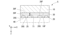
- FIG. 6 is a schematic cross-sectional view partially showing the structure of the ultrasonic unit 5 according to the fourth embodiment, and is a view seen from a direction parallel to the ultrasonic unit 5.
- the fourth embodiment differs from the first embodiment in the structure of the gel member 30.
- the ultrasonic unit 5 includes a piezoelectric element 10, an FZP member 20, and a gel member 30, similar to the first embodiment.
- the FZP member 20 is located apart from the ultrasonic wave generating surface 10F.
- the gel member 30 covers the ultrasonic generation surface 10F and the first FZP surface 20F so as to fill the slit 25 of the FZP member 20.
- the second FZP surface 20S is not covered with the gel member 30. That is, in the Z direction, the position of the second FZP surface 20S and the position of the exposed surface 30S of the gel member 30 match. In other words, the second thickness T2 of the gel member 30 is zero.
- the first thickness T1 of the gel member 30 may be changed as appropriate depending on the design of the gel member 30.
- the coating gel 40 shown in FIG. 6 is the same as in the second embodiment described above.
- the application gel 40 may be applied to the skin of the living body first, or may be applied to the exposed surface 30S.
- the coating gel 40 is not a component of the ultrasonic unit 5, but a material used when using the ultrasonic unit 5.
- the application gel 40 is applied to the skin of a living body.
- the application gel 40 is applied to the skin of a living body.
- the ultrasound unit 5 is placed on the skin via the applied gel 40. Thereby, as shown in FIG. 5, the applied gel 40 covers the entire exposed surface 30S. In this state, the ultrasonic focusing device 200 is driven.
- the ultrasound generated from the ultrasound generation surface 10F of the piezoelectric element 10 propagates to the gel member 30 located between the ultrasound generation surface 10F and the first FZP surface 20F, and reaches the FZP member 20.
- the ultrasonic waves pass through the slits 25 provided in the FZP member 20 and propagate to the coating gel 40.
- the ultrasound waves reach the skin of the living body and further reach a treatment site located away from the skin surface of the living body.
- the ultrasonic waves do not reach the skin of the living body.
- the FZP member 20 causes a diffraction phenomenon of the ultrasound waves generated from the ultrasound generation surface 10F, and focuses the ultrasound waves on the focal point that is the treatment area. In other words, the FZP member 20 can focus the ultrasonic energy to a focal point. Thereby, the FZP member 20 can provide stimulation to the treatment site.
- the gel member 30 is not arranged on the second FZP surface 20S, so the structure of the gel member 30 can be simplified. can. In particular, there is no need to adjust the second thickness T2 of the gel member 30. The thickness of the gel member 30 can be adjusted by adjusting only the first thickness T1. Therefore, the thickness of the gel member 30 can be easily controlled.
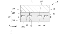
- FIG. 7 is a schematic sectional view partially showing the structure of the ultrasonic unit 6 according to the fifth embodiment, and is a view seen from a direction parallel to the ultrasonic unit 6.
- the fifth embodiment differs from the first embodiment in the structure of the gel member 30.
- the ultrasonic unit 6 includes a piezoelectric element 10, an FZP member 20, and a gel member 30 as in the first embodiment.
- Gel member 30 includes a first gel member 30A and a second gel member 30B.
- the first gel member 30A is an example of a first swelling body.
- the second gel member 30B is an example of a second swelling body.
- the first gel member 30A is located between the ultrasound generating surface 10F and the second FZP surface 20S.
- the first gel member 30A adheres the FZP member 20 to the piezoelectric element 10.
- the second gel member 30B is removable from the second FZP surface 20S. In other words, the second gel member 30B is removable from the first gel member 30A.
- the first gel member 30A has a first thickness T1.
- the second gel member 30B has a second thickness T2.
- the first gel member 30A and the second gel member 30B are made of the same material. In other words, it is preferable that the refractive index of the first gel member 30A and the refractive index of the second gel member 30B be equal to each other. Note that the first gel member 30A and the second gel member 30B may be made of different materials as long as it is possible to sufficiently reduce the degree of inhibition of ultrasonic propagation.
- the dotted line connecting the two locations indicated by symbols A and B in FIG. 7 is the surface between the first gel member 30A and the second gel member 30B.
- FIG. 7 shows an interface between the first gel member 30A and the second gel member 30B.
- This surface is a surface (separation surface) from which the second gel member 30B is peeled off from the first gel member 30A.
- the ultrasound unit 6 After finishing the treatment using the ultrasound unit 6, while leaving the first gel member 30A disposed between the piezoelectric element 10 and the FZP member 20, The used second gel member 30B that has come into contact with the skin can be peeled off from the piezoelectric element 10 and discarded.
- the ultrasonic unit 6 can be used by attaching a new second gel member 30B to the first gel member 30A. Since the second gel member 30B is easy to replace, it is possible to realize an ultrasonic unit 6 with excellent hygiene.
- FIG. 8A is a schematic cross-sectional view partially showing the structure of the diffractive gel tape according to the sixth embodiment, as viewed from a direction parallel to the diffractive gel tape.
- the diffractive gel tape 50 according to this embodiment can be used as the FZP member 20 and gel member 30 that constitute each of the ultrasonic units 4 to 6 shown in FIGS. 5 to 7.
- Diffractive gel tape 50 is an example of a diffractive swelling tape.
- the diffractive gel tape 50 includes an FZP member 20 and a gel member 30.
- the gel member 30 covers at least one of the first FZP surface 20F and the second FZP surface 20S of the FZP member 20.
- the gel member 30 covers the first FZP surface 20F and exposes the second FZP surface 20S.
- the gel member 30 may cover the second FZP surface 20S. In this case, the gel member 30 exposes the second FZP surface 20S.
- the diffraction gel tape 50 may be a tape extending in the Y direction. In this case, in the diffraction gel tape 50, a plurality of FZP members 20 are lined up in the Y direction.
- a plurality of cuts may be formed in the diffraction gel tape 50 to divide the plurality of FZP members 20 one by one.
- the plurality of cuts are lined up in the Y direction.
- the diffractive gel tape 50 can also be referred to as an adhesive tape.
- the diffraction gel tape 50 is a member in which the gel member 30 and the FZP member 20 are integrated, it can also be referred to as an integrated tape.
- Such a diffraction gel tape 50 can be directly and easily attached to the contact surface 30F of the piezoelectric element 10.
- the diffractive gel tape 50 has a first tape surface 50F and a second tape surface 50S opposite to the first tape surface 50F.
- the first tape surface 50F is a surface corresponding to the contact surface 30F of the gel member 30.
- the second tape surface 50S is a surface corresponding to the exposed surface 30S of the gel member 30. Note that the first tape surface 50F may correspond to the exposed surface 30S. In this case, the second tape surface 50S corresponds to the contact surface 30F.
- the distance between the first tape surface 50F and the first FZP surface 20F is the third thickness T3.
- the third thickness T3 corresponds to the first thickness T1 or the second thickness T2 described above.
- the diffractive gel tape 50 can adjust the focal length or the focusing rate of the ultrasound waves obtained by the ultrasound unit.
- the position of the surface of the diffraction gel tape 50 attached to the piezoelectric element 10 is not limited.
- the first tape surface 50F of the diffraction gel tape 50 may be attached to the piezoelectric element 10
- the second tape surface 50S of the diffraction gel tape 50 may be attached to the piezoelectric element 10. You can also paste it on. Note that when the diffraction gel tape 50 is applied to the ultrasonic unit 6 shown in FIG. 7, the second tape surface 50S becomes the surface with which the applied gel 40 comes into contact.
- the diffraction gel tape 50 includes a first protective sheet 51F and a second protective sheet 51S.
- the first protective sheet 51F covers the first tape surface 50F.
- the second protective sheet 51S covers the second tape surface 50S.
- Each of the first protective sheet 51F and the second protective sheet 51S has a function of protecting each of the FZP member 20 and the gel member 30. Further, each of the first protective sheet 51F and the second protective sheet 51S functions as a supporting base material that supports the FZP member 20, the gel member 30, and the diffractive gel tape 50.
- the same effects as those of the ultrasonic units 4 to 6 can be obtained. Further, after the treatment using the diffractive gel tape 50 is completed, the used diffractive gel tape 50 that has come into contact with the skin can be peeled off from the piezoelectric element 10 and discarded. By attaching a new diffraction gel tape 50 to the piezoelectric element 10, the ultrasonic unit can be used repeatedly. Since the diffraction gel tape 50 can be easily replaced, an ultrasonic unit with excellent hygiene can be realized.
- the FZP member 20 and the gel member 30 are protected by the first protective sheet 51F and the second protective sheet 51S, it is possible to prevent the FZP member 20 and the gel member 30 from being damaged.
- the first protective sheet 51F and the second protective sheet 51S are pasted on both sides of the diffractive gel tape 50, but a configuration in which the protective sheet is pasted only on one side of the diffractive gel tape 50 is also possible. May be adopted.
- FIG. 8B is a plan view partially showing a modification of the diffractive gel tape according to the sixth embodiment.
- a plurality of diffractive gel members 55 are arranged on the first protective sheet 51F.
- Each of the plurality of diffractive gel members 55 includes the FZP member 20 and gel member 30 shown in FIG. 3B.
- the plurality of diffraction gel members 55 are arranged along the extending direction of the first protective sheet 51F, that is, the Y direction.
- Each of the plurality of diffractive gel members 55 is arranged in advance on the first protective sheet 51F in a singulated state.
- the cross-sectional structure of the diffraction gel member 55 for example, the structure shown in FIG. 8A is adopted. Note that the plurality of diffraction gel members 55 may be connected by a connecting portion 56 formed of the same material as the gel member 30.
- the user When using the ultrasonic unit, the user first peels off the diffraction gel member 55 from the first protective sheet 51F. Thereafter, the user applies one side of the diffractive gel member 55 to the skin of the living body. Further, the user attaches the piezoelectric element 10 to the other surface of the diffractive gel member 55. For example, a signal cable 103 is connected to the piezoelectric element 10 in advance. Thereby, an ultrasonic unit can be realized.
- a plurality of diffractive gel members 55 may be arranged on the second protective sheet 51S. Alternatively, after pasting the piezoelectric element 10 on one surface of the diffractive gel member 55, the other surface of the diffractive gel member 55 may be pasted on the skin of the living body.
- FIG. 9 is a schematic cross-sectional view partially showing the structure of the diffractive gel tape according to the seventh embodiment, as viewed from a direction parallel to the diffractive gel tape.
- the diffraction gel tape 60 according to this embodiment can be used as the FZP member 20 and gel member 30 that constitute the ultrasonic unit 1A shown in FIGS. 2 and 3B.
- Diffractive gel tape 60 is an example of a diffractive swelling tape.
- the diffraction gel tape 60 includes the FZP member 20 and gel member 30 described in the first embodiment.
- the diffractive gel tape 60 differs from the above-described diffractive gel tape 50 in that the gel member 30 covers both the first FZP surface 20F and the second FZP surface 20S of the FZP member 20. Description of the same configuration as the diffraction gel tape 50 will be omitted.
- the diffraction gel tape 60 has a first tape surface 60F and a second tape surface 60S opposite to the first tape surface 60F.
- the first tape surface 60F is a surface corresponding to the contact surface 30F of the gel member 30. That is, the first tape surface 60F is a surface that contacts the ultrasonic wave generation surface 10F.
- the second tape surface 60S is a surface corresponding to the exposed surface 30S of the gel member 30.
- the first protective sheet 51F covers the first tape surface 60F.
- the second protective sheet 51S covers the second tape surface 60S.
- the distance between the first tape surface 60F and the first FZP surface 20F is the first thickness T1.
- the distance between the second tape surface 60S and the second FZP surface 20S is the second thickness T2.
- the diffractive gel tape 60 may be applied to the modification shown in FIG. 8B described above.
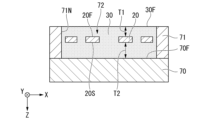
- 10A and 10B are schematic cross-sectional views partially showing the structure of the diffractive gel tape 60 according to the seventh embodiment described above, and are diagrams for explaining a method of manufacturing the diffractive gel tape 60.
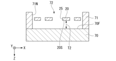
- a base 70 and a frame 71 are prepared.
- the base 70 has a base surface 70F.
- the frame 71 has a frame inner surface 71N.
- a region surrounded by the base surface 70F and the frame inner surface 71N is a mold 72 for molding the diffractive gel tape 60.
- the base 70 and the frame 71 are made of a material that has excellent releasability and liquid repellency to the urethane resin that constitutes the gel member 30. As such materials, materials such as resin materials and metal materials are used. Note that the base surface 70F and the frame inner surface 71N may have releasability or liquid repellency to the constituent material of the gel member 30.
- the FZP member 20 is placed inside the mold 72 with the frame 71 placed on the base surface 70F of the base 70.
- the height from the base surface 70F to the second FZP surface 20S of the FZP member 20 corresponds to the second thickness T2 described above. This height is set by a jig or the like that is repeatedly used only in the method of manufacturing the diffraction gel tape.
- a spacer made of a material constituting the FZP member 20 may be placed between the base surface 70F and the FZP member 20.
- the spacers may be arranged so as to be lined up in the Y direction in which the diffraction gel tape 60 extends.
- spacers may be formed near the positions of the plurality of cuts formed in the diffractive gel tape 50.
- the spacer may be separable from the FZP member 20.
- the spacer may have a shape or arrangement that allows it to be separated from the FZP members 20.
- urethane resin which is the material for the gel member 30, is poured into the mold 72.
- the urethane resin material covers the entire FZP member 20 and fills the inside of the slit 25.
- the distance between the liquid upper surface, which is the contact surface 30F of the gel member 30, and the first FZP surface 20F corresponds to the first thickness T1 described above.
- the urethane resin material is cured.
- the method of curing the urethane resin material is not particularly limited. A curing method is used depending on the type of urethane resin material.
- the base 70 and frame 71 are removed from the cured urethane resin material member.
- the first protective sheet 51F is attached to the first tape surface 60F.
- the second protective sheet 51S is attached to the second tape surface 60S.
- a diffractive gel tape 60 shown in FIG. 9 is obtained.
- the same effects as the ultrasonic unit 1 can be obtained. Furthermore, after the treatment using the diffractive gel tape 60 is completed, the used diffractive gel tape 60 that has come into contact with the skin can be peeled off from the piezoelectric element 10 and discarded. By attaching a new diffraction gel tape 60 to the piezoelectric element 10, the ultrasound unit 1 can be used repeatedly. Since the diffraction gel tape 60 can be easily replaced, it is possible to realize an ultrasonic unit 1 with excellent hygiene.
- a chamber whose internal pressure can be adjusted may be used in order to suppress air bubbles from entering the interior of the diffraction gel tape 60.
- a chamber whose internal pressure can be adjusted may be used in order to suppress air bubbles from entering the interior of the diffraction gel tape 60.
- the first urethane resin 31, which will be the material of the gel member 30, is placed inside the mold 72.
- the position of the upper surface 31A of the first urethane resin 31 in the Z direction is set so that the second thickness T2 of the gel member 30 is obtained.
- the distance between the upper surface 31A and the base surface 70F corresponds to the second thickness T2.
- the FZP member 20 is placed on the upper surface 31A of the first urethane resin 31. This determines the height from the base surface 70F to the FZP member 20 in the Z direction. In this modification, the spacer for setting the height of the FZP member 20 can be omitted.
- the method of arranging the FZP member 20 on the upper surface 31A is not limited.
- the second urethane resin 32 which is the material for the gel member 30, is poured into the mold 72.
- the second urethane resin 32 covers the entire FZP member 20 and fills the inside of the slit 25.
- the distance between the liquid upper surface 32A of the second urethane resin 32, which becomes the contact surface 30F of the gel member 30, and the first FZP surface 20F corresponds to the first thickness T1 described above.
- the second urethane resin 32 is cured.
- the base 70 and the frame 71 are removed from the first urethane resin 31 and the second urethane resin 32 after being cured.
- a diffractive gel tape 60 shown in FIG. 9 is obtained. According to this modification, the position of the FZP member 20 in the Z direction can be easily set.
- the ultrasound unit of the embodiment described above may be applied to an ultrasound unit array in which a plurality of ultrasound units are arranged.
- Examples of the ultrasonic unit array include a one-dimensional ultrasonic unit array in which a plurality of ultrasonic units are arranged one-dimensionally. Specifically, a configuration in which a plurality of ultrasonic units are lined up in the X direction or the Y direction can be adopted.
- Examples of the ultrasound unit array include a two-dimensional ultrasound unit array in which a plurality of ultrasound units are arranged two-dimensionally. Specifically, a configuration in which a plurality of ultrasonic units are lined up in both the X direction and the Y direction can be adopted. For example, in a structure in which a two-dimensional ultrasonic unit array is attached to a flat sheet, a flat array can be realized. Further, in a structure in which a two-dimensional ultrasonic unit array is attached to a deformable or stretchable sheet, a curved surface array can be realized. As described above, in the configuration in which the diffraction gel tape is attached to the piezoelectric element, a plurality of ultrasound units can be easily applied to a two-dimensional ultrasound unit array.
- ultrasonic unit, diffraction gel tape, and ultrasonic focusing device ⁇ Application examples of ultrasonic unit, diffraction gel tape, and ultrasonic focusing device>
- the present invention is not limited to an acupuncture point stimulation device that stimulates a treatment site, but may be used for treatment, diagnosis, surgery, etc. on a living body.
- a measurement unit that combines the above-mentioned ultrasound unit and a reflected wave sensor that detects reflected ultrasound waves, it is possible to realize various medical diagnostic devices and measurement devices. . Examples to which the present invention is applied are listed below.
- the ultrasonic sensor includes a measurement unit having an ultrasonic unit and a reflected wave sensor.
- the ultrasonic unit may be configured to have not only the above-mentioned function of focusing ultrasonic waves but also the function of a reflected wave sensor.
- Ultrasonic sensors can be used as sensors whose measurement position within the body can be changed. For example, a sensor is attached to the body surface of a living body directly above a blood vessel, and can obtain various information regarding the behavior of the blood vessel and the movement of blood.
- the sheet-shaped ultrasonic probe includes a plurality of measurement units each having an ultrasonic unit and a reflected wave sensor.
- the sheet-shaped ultrasonic probe may be a sheet in which a plurality of ultrasonic units configured to have not only the above-mentioned function of focusing ultrasonic waves but also the function of a reflected wave sensor are arranged.
- the plurality of ultrasound units may be arranged in a one-dimensional array arranged in a row, or may be arranged in a two-dimensional arrangement arranged in the X direction and the Y direction.
- Such an ultrasound probe is attached to the body surface of a living body.
- the sheet-like ultrasound probe may be deformable depending on the shape of the body surface.
- the sheet-like ultrasound probe may have flexibility so that it can be bent in a predetermined direction for ultrasound beamforming, ultrasound collimation, and ultrasound modulation.
- Such an ultrasonic probe can measure the carotid artery and jugular vein of a living body by applying it to the neck, for example. Furthermore, by applying the ultrasound probe to the body surface above the clavicle, it is possible to obtain various information regarding the blood in the inferior vena cava and inferior aorta.
- an ultrasonic probe can be passed between the ribs and placed inside a living body, and used to measure the shape and movement of the heart.
- Ultrasonic probes can obtain various information about the heart. Furthermore, it is also possible to perform image processing such as cardiac imaging based on the information obtained by the ultrasound probe. Additionally, by attaching an ultrasound probe to the surface of the neck, it is possible to measure the movement of the throat and evaluate the muscles that move the epiglottis.
- FIG. 12A is a cross-sectional view schematically showing the ultrasound unit according to Examples 1 and 2, and is a diagram for explaining simulation conditions.
- FIG. 12B is a cross-sectional view schematically showing the ultrasound unit according to Example 1, and is a diagram for explaining a simulation analysis model.
- FIG. 12C is a diagram showing the simulation results of the ultrasound unit according to Example 1, and is a graph showing the relationship between the design focal length (mm) and the focal length FL (mm) from the skin surface SF.
- FIG. 12D is a diagram showing the simulation results of the ultrasound unit according to Example 1, and is a graph showing the relationship between the design focal length (mm) and the ultrasound intensity (kW/m 2 ).
- FIG. 12E is a diagram showing the simulation results of the ultrasound unit according to Example 1, and is a graph showing the relationship between the focal length FL (mm) from the skin surface SF and the ultrasound intensity (kW/m 2 ). It is.
- the ultrasound unit 1 shown in FIG. 3A is used.
- the symbol W is water used as an example of skin in the simulation.
- the symbol WB indicates an open interface.
- the symbol SF corresponds to the exposed surface 30S of the gel member 30 constituting the ultrasound unit 1, and indicates the skin surface. On the skin surface SF, the exposed surface 30S is in contact with water W.
- Symbol FL indicates focal length. That is, the focal length FL means the distance from the skin surface SF toward the inside of the skin.
- the symbol UW indicates an ultrasonic wave generated from the ultrasonic wave generating surface 10F.
- the frequency of the ultrasonic waves generated from the piezoelectric element 10 was set to 3 MHz.
- the sound pressure was 2.8 ⁇ 10 4 Pa.
- the sound pressure means the pressure generated on the ultrasonic generation surface of the piezoelectric element 10.
- the FZP member 20 was formed using acrylic resin.
- the gel member 30 was formed using human skin gel stock solution (registered trademark). The density of the gel member 30 is approximately 998.6 kg/m 3 , and the propagation speed of ultrasonic waves in the gel member 30 is 1141.5 m/s.
- the design focal length was adjusted so that the focal length FL was approximately 3 mm and the strongest ultrasound intensity was obtained.
- the thickness of the FZP member 20, the width of the slit 25, and the thickness of the gel member 30 were adjusted. Since the frequency of ultrasonic waves is 3 MHz, the thickness of the FZP member 20 was set to 0.4 mm.
- the width of the slit 25 was adjusted within the range of 0.4 mm to 1.0 mm.
- the thickness of the gel member 30 was adjusted within the range of 0.4 mm to 2.4 mm.
- the position where the ultrasonic intensity is 30 kW/m 2 is indicated by a thick line.
- This intensity refers to the ultrasonic intensity that was found to be actually effective when a test was conducted in which acupuncture point stimulation using focused ultrasound was conducted using an acupuncture point stimulation device equipped with an ultrasonic unit. Specifically, this means that the ultrasonic intensity is 30 kW/m 2 at the focal position. Note that the meaning of the ultrasonic intensity of 30 kW/m 2 indicated by the thick line in the drawings explaining Comparative Example, Example 2, and Example 3, which will be described later, is the same as in FIGS. 12D and 12E.
- FIG. 13A is a cross-sectional view schematically showing an ultrasound unit of a comparative example, and is a diagram for explaining simulation conditions.
- FIG. 13B is a cross-sectional view schematically showing an ultrasound unit of a comparative example, and is a diagram for explaining a simulation analysis model.
- FIG. 13C is a diagram showing the simulation results of the ultrasound unit of the comparative example, and is a graph showing the relationship between the focal length FL (mm) and the radius of curvature (mm) of the acoustic lens.
- FIG. 13D is a diagram showing the simulation results of the ultrasound unit of the comparative example, and is a graph showing the relationship between the focal length FL (mm) and the ultrasound intensity (kW/m 2 ).
- an ultrasound unit 501 including an acoustic lens having a concave surface portion is used.
- the ultrasonic unit 501 includes a piezoelectric element 510 having an ultrasonic generation surface 510F, an acoustic lens 520 having a concave portion 521, a gel member 530 provided on the surface of the concave portion 521, and an acoustic lens on the ultrasonic generation surface 510F. 520 and an adhesive tape 540 for adhering the adhesive tape 520.
- the gel member 530 has an exposed surface 530S that comes into contact with water W, which is used as an example of skin in the simulation.
- the exposed surface 530S corresponds to the skin surface SF.
- the piezoelectric element 510 has the same configuration as the piezoelectric element 10 that constitutes the ultrasound unit 1.
- the focal length FL is the distance from the skin surface SF toward the inside of the skin.
- the ultrasonic waves UW are generated from the ultrasonic wave generating surface 510F.
- the distance between the edge 520E of the acoustic lens 520 and the skin surface SF is set to 1 mm.
- Acoustic lens 520 has a radius of curvature R (mm). In the comparative example, the radius of curvature R was adjusted within the range of 3 to 19.
- the frequency of the ultrasonic waves generated from the piezoelectric element 510 was set to 2 MHz or 3 MHz.
- the sound pressure was 1.0 ⁇ 10 5 Pa.
- the sound pressure means the pressure generated on the ultrasonic generation surface of the piezoelectric element 510.
- Acoustic lens 520 was formed using acrylic resin.
- the material of the gel member 530 is the same as that of the gel member 30.
- the gel member 30 constituting the ultrasound unit 1 according to the second embodiment includes a first gel region 35 having a first thickness T1 and a second gel region 36 having a second thickness T2. and has.
- the first gel region 35 is located between the first FZP surface 20F and the ultrasound generation surface 10F.
- the second gel region 36 is located between the second FZP surface 20S and the skin surface SF (exposed surface 30S).
- the focal length or ultrasonic intensity in each case of the first thickness T1 and the second thickness T2 was analyzed.
- the simulation conditions of Example 2 are the same as those of Example 1 described above. Simulations were performed for a case where the diameter of the piezoelectric element 10 is 5 mm and a case where the diameter of the piezoelectric element 10 is 6 mm.
- FIG. 14A is a diagram showing the simulation results of the ultrasound unit according to Example 2, and is a graph showing the relationship between the focal length FL (mm) and the second thickness T2 (mm) of the second gel region 36. It is.
- FIG. 14B is a diagram showing the simulation results of the ultrasound unit according to Example 2, and is a graph showing the relationship between the focal length FL (mm) and the first thickness T1 (mm) of the first gel region 35.
- FIG. 14C is a diagram showing the results of a simulation of the ultrasound unit according to Example 2, showing the relationship between the second thickness T2 (mm) of the second gel region 36 and the ultrasound intensity (kW/m 2 ). This is a graph showing.
- FIG. 14D is a diagram showing the results of a simulation of the ultrasound unit according to Example 2, showing the relationship between the first thickness T1 (mm) of the first gel region 35 and the ultrasound intensity (kW/m 2 ). This is a graph showing.
- the symbol “D5mm” indicates that the diameter of the piezoelectric element 10 is 5mm.
- the symbol “D6mm” indicates that the diameter of the piezoelectric element 10 is 6mm.
- the symbol “t0.0 mm” indicates that the thickness of the gel region is 0.0 mm.
- the symbol “t0.4 mm” indicates that the thickness of the gel region is 0.4 mm.
- the symbol “t0.8 mm” indicates that the thickness of the gel region is 0.8 mm.
- the symbol “t1.2 mm” indicates that the thickness of the gel region is 1.2 mm.
- FIG. 15 is a diagram showing the results of comparing Example 1 and Comparative Example regarding the maximum ultrasonic intensity under Conditions 1 to 4.
- condition 1 the diameter of the piezoelectric element 10 is 5 mm, and the focal length FL is 3 mm.
- condition 2 the diameter of the piezoelectric element 10 is 5 mm, and the focal length FL is 5 mm.
- condition 3 the diameter of the piezoelectric element 10 is 6 mm, and the focal length FL is 3 mm.
- condition 4 the diameter of the piezoelectric element 10 is 6 mm, and the focal length FL is 5 mm.
- Example 4 will be described with reference to FIGS. 16 to 30.
- FIG. 17 is a diagram showing the configuration of a test device used in Example 4.
- 18 to 30 show simulation results and experimental results using the test device 80.
- the results of experiments using the test apparatus 80 may be simply referred to as "experiment results.”
- Example 4 Based on the simulation results obtained in Examples 1 to 3 described above, the effects of the present invention were further verified in Example 4.
- simulations were performed for examples involving four lenses and comparative examples that do not use lenses (FZP members).
- FZP members lenses
- gel members that constitute the ultrasonic unit.
- Each of the four manufactured lenses is an integral body of the FZP member and gel member described in the above embodiment. In the following description, the four lenses will be referred to as lenses 1 to 4.
- FIG. 16 is a table showing conditions for lenses 1 to 4 (lens 1 to 4).
- PZT diameter means the diameter of the piezoelectric element 10.
- R1 to R4 described in "FZP lens size” correspond to R1 to R4 of the FZP member 20 shown in FIG. 3B.
- the symbol R1 is the distance from the center O of the ultrasound unit 1A to the inner edge of the inner FZP section 21 in the radial direction, that is, the inner diameter of the inner FZP section 21.
- the symbol R2 is the distance from the center O of the ultrasound unit 1A to the outer edge of the inner FZP section 21 in the radial direction, that is, the outer diameter of the inner FZP section 21.
- the symbol R3 is the distance from the center O of the ultrasound unit 1A to the inner edge of the outer FZP section 22 in the radial direction, that is, the inner diameter of the outer FZP section 22.
- the symbol R4 is the distance from the center O of the ultrasound unit 1A to the outer edge of the outer FZP section 22 in the radial direction, that is, the outer diameter of the outer FZP section 22.
- the symbol R4 is the distance from the center O of the ultrasonic unit 1A to the outer peripheral edge of the FZP member 20 in the radial direction, that is, the diameter of the FZP member 20.
- “Gel thickness” means the thickness of the gel member 30 shown in FIG. 12A.
- “t1” corresponds to the first thickness T1, which is the thickness of the first gel region 35.
- “t2” corresponds to the second thickness T2, which is the thickness of the second gel region 36.
- Lenses 1 to 4 differ from each other in "PZT diameter,”"FZP lens size,” and “Gel thickness.”
- the lenses 1 to 4 used in the experiment using the test device 80 differ from those in the simulation in that a connecting portion 23 is used. Specifically, in the lenses 1 to 4 used in the experiment using the test apparatus 80, the inner FZP section 21 and the outer FZP section 22 are connected by the connecting part 23, as shown in FIG. 3B. In contrast, each of the lenses 1 to 4 used in the simulation has a structure in which the inner FZP section 21 and the outer FZP section 22 are not connected by the connecting section 23.
- FIG. 20, FIG. 22, FIG. 24, FIG. 26, and FIG. 28 each show the results of the following simulations.
- ⁇ Figure 18 Simulation results of a comparative example using only a piezoelectric element with a diameter of 6 mm without using a lens (FZP member)
- ⁇ Figure 20 Simulation results for lens 1
- Figure 22 Simulation results for lens 2
- Figure 24 Lens Simulation results of a comparative example using only a piezoelectric element with a diameter of 5 mm without using (FZP member)
- Figure 26 Simulation results of lens 3 - Figure 28: Simulation results of lens 4
- the horizontal axis indicates the position (mm) on the surface of the body surface.
- the vertical axis indicates the depth (mm) from the body surface.
- the "body surface” corresponds to the surface of the skin of a living body.
- an ultrasonic intensity distribution of 0 to 1.8 kW/m 2 is obtained.
- the symbol S0 indicates a region where the ultrasonic intensity was 0 to 0.18 kW/m 2 .
- Symbol S1 indicates a region where the ultrasonic intensity was 0.18 to 0.36 kW/m 2 .
- Symbol S2 indicates a region where the ultrasonic intensity was 0.36 to 0.54 kW/m 2 .
- Symbol S3 indicates a region where the ultrasonic intensity was 0.54 to 0.72 kW/m 2 .
- Symbol S4 indicates a region where the ultrasonic intensity was 0.72 to 0.90 kW/m 2 .
- Symbol S5 indicates a region where the ultrasonic intensity was 0.90 to 1.08 kW/m 2 .
- Symbol S6 indicates a region where the ultrasonic intensity was 1.08 to 1.26 kW/m 2 .
- Symbol S7 indicates a region where the ultrasonic intensity was 1.26 to 1.44 kW/m 2 .
- Symbol S8 indicates a region where the ultrasonic intensity was 1.44 to 1.62 kW/m 2 .
- Symbol S9 indicates a region where the ultrasonic intensity was 1.62 to 1.80 kW/m 2 .
- S3 to S9 for areas where multiple areas where the ultrasound intensity continuously increases are concentrated in an elliptical shape, multiple areas may be written together as "S3 to S9", for example. There is.
- the test apparatus 80 includes a computer 81, a display 82, an oscilloscope 83, a movable stage 84, an ultrasonic generator 85, a hydrophone 86, a device 87, and a water tank 88. .
- the computer 81 has a control section that centrally controls the test apparatus 80, and a storage section that stores the conditions of the lenses 1 to 4, test results, etc.
- the display 82 displays the conditions and test results of the lenses 1 to 4.
- Display 82 is connected to computer 81 .
- the oscilloscope 83 is connected to the hydrophone 86 and acquires signal data detected by the hydrophone 86.
- Oscilloscope 83 is connected to computer 81.
- the movable stage 84 can move the hydrophone 86 in the horizontal direction under the control of the computer 81.
- the ultrasonic generator 85 includes, for example, a function generator that generates an electrical signal such as a sine wave or a rectangular wave, and an amplifier.
- the ultrasonic generator 85 corresponds to, for example, the device main body 100 shown in FIG. 1.
- the hydrophone 86 is, for example, a sensor that measures an underwater ultrasonic sound field.
- Device 87 is replaceable and connected to ultrasound generator 85 .
- Device 87 corresponds to an ultrasound unit.
- Water tank 88 contains water. Under water in the water tank 88, the device 87 and the hydrophone 86 are arranged to face each other.
- the hydrophone 86 was moved horizontally by 0.5 mm by driving the movable stage 84, and the ultrasonic intensity at the position after the movement was measured.
- FIG. 21, FIG. 23, FIG. 25, FIG. 27, and FIG. 29 each show the following experimental results using the test apparatus 80.
- ⁇ Figure 19 Experimental results of a comparative example using only a piezoelectric element with a diameter of 6 mm without using a lens (FZP member)
- ⁇ Figure 21 Experimental results of lens 1
- Figure 23 Experimental results of lens 2
- Figure 25 Lens Experimental results of a comparative example using only a piezoelectric element with a diameter of 5 mm without using (FZP member)
- Figure 27 Experimental results of lens 3
- Figure 29 Experimental results of lens 4
- the horizontal axis indicates the position (mm) on the surface of the body surface.
- the vertical axis indicates the depth (mm) from the body surface.
- the "body surface” corresponds to the surface of the skin of a living body.
- water is used. The reason for using water is that the physical properties of water are close to those of the skin.
- the "body surface” corresponds to the interface between the device 87 and water. In other words, it corresponds to the interface between the lens and water. In this experimental result, each of the plurality of measured values is normalized.
- a plurality of calculated values are obtained by extracting the maximum value from among a plurality of measured values indicating ultrasonic intensity and dividing each of the plurality of measured values by the maximum value. Therefore, the normalized calculated value is within the range of 0 to 1.0.
- the symbol V1 indicates a portion where the calculated value was 0 to 0.2.
- the code V2 indicates a portion where the calculated value was 0.2 to 0.4.
- the code V3 indicates a portion where the calculated value was 0.4 to 0.6.
- the code V4 indicates a portion where the calculated value was 0.6 to 0.8.
- the code V5 indicates a portion where the calculated value was 0.8 to 1.0.
- FIG. 30 is a table summarizing simulation results (Simulation) and experimental results (Measured) for Lenses 1 to 4 regarding Example 4.
- focus depth, focal area (Area size of focal point), and convergence rate are shown.
- the focal area means the range that is irradiated with an intensity of 50% or more of the maximum intensity.
- the focusing rate (dB) is a value obtained by comparing the maximum intensity of each of lenses 1 to 4 with respect to the maximum intensity of a comparative example in which no FZP member is attached.
Landscapes
- Engineering & Computer Science (AREA)
- Health & Medical Sciences (AREA)
- Mechanical Engineering (AREA)
- Acoustics & Sound (AREA)
- Physics & Mathematics (AREA)
- Multimedia (AREA)
- Life Sciences & Earth Sciences (AREA)
- Veterinary Medicine (AREA)
- Public Health (AREA)
- Nuclear Medicine, Radiotherapy & Molecular Imaging (AREA)
- Surgery (AREA)
- Signal Processing (AREA)
- Animal Behavior & Ethology (AREA)
- General Health & Medical Sciences (AREA)
- Biomedical Technology (AREA)
- Otolaryngology (AREA)
- Radiology & Medical Imaging (AREA)
- Heart & Thoracic Surgery (AREA)
- Medical Informatics (AREA)
- Molecular Biology (AREA)
- Surgical Instruments (AREA)
Abstract
Description
本願は、2022年3月30日に日本に出願された特願2022-055687号に基づき優先権を主張し、その内容をここに援用する。
実施形態の説明では、同一又は類似の機能を有する構成に同一の符号を付す。構成の重複する説明は省略する場合がある。図面は模式的又は概念的なものであり、各部分の厚さと幅との関係、部分間の大きさの比率等は、必ずしも現実のものと同一とは限らない。
<超音波集束装置の構造>
図1は、超音波集束装置200の構成の一例を示す機能ブロック図である。
超音波集束装置200は、超音波ユニット1と、装置本体100と、信号ケーブル103とを備える。装置本体100は、交流電圧発生部101と、信号発生部102とを備える。超音波ユニット1は、信号ケーブル103を介して、装置本体100の信号発生部102に電気的に接続されている。超音波ユニット1は、信号発生部102から受信した周波数信号に基づき、超音波を発生させる。
以下の説明では、外部電源を利用する超音波集束装置200について説明する。
交流電圧発生部101は、超音波集束装置200に内蔵された配線を介して信号発生部102に接続されている。交流電圧発生部101は、信号発生部102に交流電圧を供給するように構成されている。交流電圧発生部101は、外部電源から超音波集束装置200に供給された交流電力を昇圧するように構成された回路である。交流電圧発生部101は、例えば、トランスやインバータを備える。信号発生部102に交流電圧を供給可能であれば、交流電圧発生部101の回路構成は限定されず、公知の回路が用いられてもよい。交流電圧発生部101を、電力増幅器と称することもできる。
信号発生部102は、信号ケーブル103を介して超音波ユニット1に接続されている。信号発生部102は、超音波ユニット1に周波数信号を供給するように構成された回路である。周波数信号に関し、超音波ユニット1による効果を十分に得ることが可能であれば、周波数の数値、信号波形、電圧値等は、特に限定されない。
図2は、第1実施形態に係る超音波ユニット1の構造を部分的に示す模式断面図であって、超音波ユニット1に平行な方向から見た図である。図3Aは、第1実施形態に係る超音波ユニット1の構造を部分的に示す模式断面図であって、超音波ユニット1の厚さ方向から見た図である。
FZP部材20は、透過型回折部の一例である。
ゲル部材30は、膨潤体の一例である。
超音波ユニット1のX方向及びY方向における幅、すなわち、超音波ユニット1の直径は、例えば、約5mm~6mmである。ただし、本実施形態は、超音波ユニット1の直径を限定しない。
超音波ユニット1のZ方向の長さ、すなわち、超音波ユニット1の厚さは、超音波ユニット1を構成するFZP部材20及びゲル部材30の厚さに応じて超音波ユニット1の厚さを適宜変更可能である。
超音波ユニット1における圧電素子10とFZP部材20との位置関係に関し、図2に示す構造では、圧電素子10とFZP部材20とが離間しているが、圧電素子10はFZP部材20から離間していなくてもよい。言い換えると、FZP部材20は、圧電素子10に接触するように圧電素子10上に位置してもよい。また、図2及び図3Aに示す例では、FZP部材20は、圧電素子10とは異なる部材で構成されている。
圧電素子10は、圧電効果を利用した受動素子である。具体的に、圧電素子10は、上部電極と、下部電極と、上部電極と下部電極との間に挟持された圧電体を備える。信号発生部102から圧電素子10に供給される周波数信号の電圧は、上部電極及び下部電極に印加される。上部電極と下部電極との間に印加された周波数信号の電圧は、圧電体に付与され、圧電体が振動する。つまり、圧電素子10は、圧電素子10に付与された電圧信号を振動運動に変換するように構成されている。
図2及び図3Aに示す例では、圧電素子10は、Z方向に見て超音波ユニット1と同様の形状を有するが、圧電素子10の形状は特に限定されない。超音波ユニット1の製造コスト低減の点で、圧電素子10は、従来から流通している市販品であることが好ましい。
FZP部材20は、スリット25を有する平板部材である。
FZP部材20は、音響レンズの一例である。
本実施形態においては、FZP部材20は、内側FZP部21と、外側FZP部22とを有する。外側FZP部22は、内側FZP部21を囲むように位置している。内側FZP部21と外側FZP部22とは互いに離間している。内側FZP部21と外側FZP部22との間にスリット25が形成されている。
内側FZP部21は、第1部材の一例である。
外側FZP部22は、第2部材の一例である。
FZP部材20を用いる超音波ユニット1においては、超音波の周波数に依存して、焦点距離が調整することが可能である。
言い換えると、超音波集束装置200から圧電素子10に供給される周波数信号や圧電素子10から発生する超音波の周波数に応じて、FZP部材20の構成を調整することが可能である。
また、文言「焦点距離」は、超音波ユニット1におけるZ方向の端部から焦点までの距離に相当する。言い換えると、文言「焦点距離」は、ゲル部材30の露出面30Sと焦点との間の距離、すなわち、生体の皮膚の表面と治療部位との間の距離に相当する。
第1FZP面20Fは、第1面の一例である。
第2FZP面20Sは、第2面の一例である。
FZP部材20の母材となる平板部材にスリット25を形成する方法は、例えば、レーザ加工、切削加工、エッチング等が採用される。目的とするスリット25の幅を確保することが可能であれば、スリット25の加工には高い精度は要求されない。
図3Bは、第1実施形態に係る超音波ユニット1Aを構成するFZP部材20の変形例を部分的に示す模式断面図であって、超音波ユニット1Aの厚さ方向から見た図である。
図3Bに示すFZP部材20は、内側FZP部21と外側FZP部22との間に連結部が設けられている点で、図3Aに示すFZP部材20とは異なる。
互いに隣り合う2つの周辺開口部P2は、周方向において離間している。言い換えると、4つの周辺開口部P2は、連結部23によって形成された離間部分を有する環状形状と称してもよい。
図3A及び図3Bに示す例において、FZP部材20が備えるスリットパターンSPは、同心円パターンであるが、スリットパターンSPは同心円パターンに限定されない。FZP部材20は、X方向、Y方向、又はX方向に対して斜めに傾斜する斜め方向に、直線的に延在するスリットパターンSPを有してもよい。つまり、FZP部材20は、ラインアンドスペースパターンを有する回折格子を備えてもよい。さらに、FZP部材20が備えるスリットパターンSPとして、渦巻状のパターンが採用されてもよい。
図3A及び図3Bに示す例において、中心開口部P1の形状は、円形であったが、中心開口部P1の形状として他の形状が採用されてもよい。例えば、中心開口部P1が長孔形状を有してもよいし、楕円形状を有してもよい。
一定のスリット幅が得られることが可能であれば、中心開口部P1の形状に応じて、1つ又は複数の周辺開口部P2により形成される環状形状を変更してもよい。
FZP部材20は、超音波のビームフォーミング、超音波のコリメーション、超音波のモデュレーションを行ってもよい。
スリット25の幅が互いに異なる複数の種類のFZP部材、すなわち、N種類(Nは2以上の整数)のFZP部材を用意することも可能である。
具体的に説明すると、まず、治療対象の種類、治療部位の種類、焦点距離の種類、又は超音波の集束率の種類に応じて設定された複数の種類のFZP部材の設計が行われる。種類のFZP部材の設計においては、スリット25の幅を自由に選択し、各スリット25に関する実験やシミュレーションを行うことで、治療対象の種類、治療部位の種類、焦点距離の種類、又は超音波の集束率の種類に応じたスリット25の幅が決定される。
言い換えると、スリット25の幅を調整しながら実験やシミュレーションを行うことで、治療対象、治療部位、焦点距離、又は超音波の集束率に応じたスリット25を決定することができる。
なお、FZP部材の設計においては、スリット25の幅の決定だけでなく、スリットパターンSPを設計してもよい。互いに異なるスリットパターンSPが設計されてもよい。
ここで、「適切なスリット25を有するFZP部材」とは、実際の治療に用いるFZP部材であって、超音波ユニット1を使用する使用者が目的とする治療対象、目的とする治療部位、目的とする焦点距離、又は目的とする超音波の集束率を考慮して選択するFZP部材である。
したがって、複数のFZP部材から適切なFZP部材を選択することで、超音波ユニット1における焦点距離又は超音波の集束率を調整することが可能となる。言い換えると、スリット25の幅を調整することで、焦点距離又は超音波の集束率を調整することができる。
ゲル部材30は、固体高分子と水等の溶媒とを含むゲル状態の部材である。言い換えると、ゲル部材30は、弾性変形が可能な部材である。ゲル部材30は、固体高分子が溶媒を吸収することで体積が増大した構造を有する。
ゲル部材30は、超音波発生面10Fに接触する接触面30Fと、接触面30Fとは反対側の面であって超音波ユニット1の外部に露出する露出面30Sとを有する。
すなわち、ゲル部材30は、第1FZP面20Fと超音波発生面10Fとの間に配置されており、かつ、第2FZP面20S上にも配置されている。さらに、ゲル部材30は、スリット25の内部にも配置されている。
硬化されたゲル部材30は、流体ではないため、ゲル部材30の内部におけるFZP部材20の位置は安定的に維持される。
したがって、ゲル部材30の接触面30Fは、超音波発生面10Fに対し、直接的かつ容易に貼り付けることが可能である。言い換えると、ゲル部材30は、少なくともFZP部材20を圧電素子10に粘着されている。
また、ゲル部材30は、超音波発生面10Fから容易に剥離することも可能である。言い換えると、ゲル部材30及びFZP部材20が一体化された一体物は、圧電素子10に対して着脱可能であり、圧電素子10を廃棄することなく、一体物のみを使い捨てることが可能である。
具体的に、Z方向において、ゲル部材30は、第1FZP面20Fと接触面30Fとの間の距離に相当する第1厚さT1を有する。さらに、ゲル部材30は、第2FZP面20Sと露出面30Sとの間の距離に相当する第2厚さT2を有する。第1厚さT1及び第2厚さT2の少なくとも一方を調整することで、ゲル部材30は、露出面30Sから焦点までの焦点距離又は超音波の集束率を調整することが可能である。
厚さ条件が互いに異なる複数の種類のゲル部材、すなわち、N種類(Nは2以上の整数)のゲル部材を用意することも可能である。ここで、厚さ条件とは、第1厚さT1及び第2厚さT2を意味する。
具体的に説明すると、まず、治療対象の種類、治療部位の種類、焦点距離の種類、又は超音波の集束率の種類に応じて設定された複数の種類のゲル部材の設計が行われる。種類のゲル部材の設計においては、第1厚さT1及び第2厚さT2の少なくとも一方を自由に選択し、すなわち、厚さ条件を自由に選択する。選択された条件においてゲル部材に関する実験やシミュレーションを行うことで、治療対象の種類、治療部位の種類、焦点距離の種類、又は超音波の集束率の種類に応じた厚さ条件が決定される。
言い換えると、厚さ条件を調整しながら実験やシミュレーションを行うことで、治療対象、治療部位、焦点距離、又は超音波の集束率に応じた厚さ条件を決定することができる。
ここで、「適切な厚さ条件を有するゲル部材」とは、実際の治療に用いるゲル部材であって、超音波ユニット1を使用する使用者が目的とする治療対象、目的とする治療部位、目的とする焦点距離、又は目的とする超音波の集束率を考慮して選択するゲル部材である。
したがって、複数のゲル部材から適切なゲル部材を選択することで、超音波ユニット1における焦点距離又は超音波の集束率を調整することが可能となる。言い換えると、第1厚さT1及び第2厚さT2の少なくとも一方を調整することで、焦点距離又は超音波の集束率を調整することができる。
超音波集束装置200を使用する使用者は、超音波ユニット1の外部に露出する露出面30Sを生体の皮膚に接触させる。この状態で、超音波集束装置200が駆動する。
なお、超音波集束装置200が駆動した状態で、露出面30Sを生体の皮膚に接触させてもよい。
FZP部材20を形成する際においては、高い精度を必要とせずにスリット25を平板部材に形成することができる。このため、FZP部材20の形成工程が極めて単純である。言い換えると、従来の音響レンズを形成する際には、高精度の曲率を有する球面を凹面部に加工する必要があり、加工の難易度が高く、加工コストを低減することが難しかった。
これに対し、超音波ユニット1によれば、音響レンズとして機能するFZP部材20を容易に形成することができるので、FZP部材20を備える超音波ユニット1の加工コストを低減することができる。
これに対し、超音波ユニット1によれば、粘着性を有するゲル部材30を超音波発生面10Fに貼り付けるだけで、超音波ユニット1を得ることができる。したがって、接着テープを用いて音響レンズを圧電素子に貼り付ける構造と比較して、超音波ユニット1を構成する部材の個数を削減することができる。このため、超音波ユニット1を容易に製造することができるので、FZP部材20を備える超音波ユニット1の加工コストを低減することができる。
これに対し、超音波ユニット1によれば、接着テープを用いることなく、粘着性を有するゲル部材30が超音波発生面10Fに貼り付けられた構成を有する。このため、従来の構成よりも、界面の数が少ないため超音波の減衰を抑制することができる。
これに対し、FZP部材20を備える超音波ユニット1は、凹面部を用いない構造であるため、従来の超音波治療装置とは異なり、超音波ユニット1に空気が入り込みにくい。したがって、凹面部内に残留する空気に起因して超音波が減衰するという問題を解消することができる。
これに対し、ゲル部材30を備える超音波ユニット1は、生体の皮膚上にゲルを塗布することなく、ゲル部材30の露出面30Sに皮膚を接触させ、超音波ユニット1を使用することができる。ゲル部材30は、圧電素子10から容易に剥離することが可能であるため、超音波ユニット1を用いた治療を終えた後に、皮膚に接触した使用済みのゲル部材30を圧電素子10から剥離し、廃棄することができる。新たなゲル部材30を圧電素子10に貼り付けることで、超音波ユニット1を使用することができる。ゲル部材30の交換が容易であるため、衛生面に優れた超音波ユニット1を実現することができる。
次に、超音波ユニットの他の実施形態について説明する。
以下に説明する実施形態においては、第1実施形態と同一部材には同一符号を付して、その説明は省略または簡略化する。第1実施形態において説明した構成とは異なる構成を主に説明する。説明の省略に関し、例えば、経穴刺激装置として使用される超音波集束装置200の駆動に関する説明は、省略されている。
図4は、第2実施形態に係る超音波ユニット3の構造を部分的に示す模式断面図であって、超音波ユニット3に平行な方向から見た図である。
第2実施形態は、圧電素子の超音波発生面にFZP部材が接触している点で、第1実施形態とは異なる。さらに、第2実施形態においては、ゲル部材30を用いない。
まず、塗布ゲル40を生体の皮膚に塗布する。塗布ゲル40を介して、超音波ユニット3が皮膚に配置される。これにより、図4に示すように塗布ゲル40は、超音波発生面10Fに接触する。塗布ゲル40は、FZP部材20のスリット25を埋めるように超音波発生面10F及び第2FZP面20Sの全体を被覆する。この状態で、超音波集束装置200が駆動する。
図5は、第3実施形態に係る超音波ユニット4の構造を部分的に示す模式断面図であって、超音波ユニット4に平行な方向から見た図である。
第3実施形態は、圧電素子の超音波発生面にFZP部材が接触している点で、第1実施形態とは異なる。
まず、ゲル部材30の露出面30Sを生体の皮膚に接触させる。この状態で、超音波集束装置200が駆動する。
圧電素子10の超音波発生面10Fから発生した超音波は、スリット25を通り、ゲル部材30に伝搬する。超音波は、生体の皮膚に到達し、さらに、生体の皮膚面から離れた位置にある治療部位に到達する。一方、FZP部材20においてスリット25が設けられていない部位では、超音波は、生体の皮膚に到達しない。
図6は、第4実施形態に係る超音波ユニット5の構造を部分的に示す模式断面図であって、超音波ユニット5に平行な方向から見た図である。
第4実施形態は、ゲル部材30の構造の点で、第1実施形態とは異なる。
まず、塗布ゲル40を生体の皮膚に塗布する。塗布ゲル40を介して、超音波ユニット5が皮膚に配置される。これにより、図5に示すように塗布ゲル40は、露出面30Sの全体を被覆する。この状態で、超音波集束装置200が駆動する。
図7は、第5実施形態に係る超音波ユニット6の構造を部分的に示す模式断面図であって、超音波ユニット6に平行な方向から見た図である。
第5実施形態は、ゲル部材30の構造の点で、第1実施形態とは異なる。
第1ゲル部材30Aは、第1膨潤体の一例である。
第2ゲル部材30Bは、第2膨潤体の一例である。
なお、超音波の伝搬の阻害の程度を十分に低減することが可能であれば、第1ゲル部材30Aと第2ゲル部材30Bとは互いに異なる材料で構成されてもよい。
本実施形態に係る超音波ユニット6によれば、超音波ユニット6を用いた治療を終えた後に、圧電素子10とFZP部材20との間に配置された第1ゲル部材30Aを残留させつつ、皮膚に接触した使用済みの第2ゲル部材30Bを圧電素子10から剥離し、廃棄することができる。新たな第2ゲル部材30Bを第1ゲル部材30Aに貼り付けることで、超音波ユニット6を使用することができる。第2ゲル部材30Bの交換が容易であるため、衛生面に優れた超音波ユニット6を実現することができる。
図8Aは、第6実施形態に係る回折ゲルテープの構造を部分的に示す模式断面図であって、回折ゲルテープに平行な方向から見た図である。
本実施形態に係る回折ゲルテープ50は、図5~図7に示す超音波ユニット4~6の各々を構成するFZP部材20及びゲル部材30として用いることができる。
回折ゲルテープ50は、回折膨潤テープの一例である。
本実施形態では、ゲル部材30は、第1FZP面20Fを被覆しており、第2FZP面20Sを露出させている。なお、ゲル部材30は、第2FZP面20Sを被覆してもよい。この場合、ゲル部材30は、第2FZP面20Sを露出させる。
Y方向に延在する回折ゲルテープ50に複数の切り込みが予め形成されていることで、回折ゲルテープ50を使用する使用者は、複数のFZP部材20を一ずつに容易に分離することが可能である。
なお、以下の説明では、Y方向に延在する回折ゲルテープの一部の断面について説明する。後述する図9~図11における説明も同様である。
第1保護シート51F及び第2保護シート51Sの各々は、FZP部材20及びゲル部材30の各々を保護する機能を有する。また、第1保護シート51F及び第2保護シート51Sの各々は、FZP部材20、ゲル部材30、及び回折ゲルテープ50を支持する支持基材として機能する。
本実施形態に係る回折ゲルテープ50によれば、超音波ユニット4~6と同様の効果が得られる。さらに、回折ゲルテープ50は、回折ゲルテープ50を用いた治療を終えた後に、皮膚に接触した使用済みの回折ゲルテープ50を圧電素子10から剥離し、廃棄することができる。新たな回折ゲルテープ50を圧電素子10に貼り付けることで、超音波ユニットを繰り返し使用することができる。回折ゲルテープ50の交換が容易であるため、衛生面に優れた超音波ユニットを実現することができる。
なお、図8Aに示す例では、回折ゲルテープ50の両面に第1保護シート51F及び第2保護シート51Sが貼られているが、回折ゲルテープ50に一方の面のみに保護シートが貼られた構成が採用されてもよい。
図8Bは、第6実施形態に係る回折ゲルテープの変形例を部分的に示す平面図である。
回折ゲルテープ50においては、第1保護シート51F上に複数の回折ゲル部材55が配置している。複数の回折ゲル部材55の各々は、図3Bに示すFZP部材20とゲル部材30とを有する。複数の回折ゲル部材55は、第1保護シート51Fの延在方向、すなわち、Y方向に沿って並んでいる。複数の回折ゲル部材55の各々は、予め、個片化された状態で第1保護シート51F上に配置されている。
回折ゲル部材55の断面構造は、例えば、図8Aに示す構造が採用される。
なお、複数の回折ゲル部材55は、ゲル部材30と同一の材料で形成された接続部56によって繋がっていてもよい。
なお、第1保護シート51Fに代えて、第2保護シート51S上に複数の回折ゲル部材55が配置されてもよい。
また、回折ゲル部材55の一方の面に圧電素子10を貼った後、回折ゲル部材55の他方の面を生体の皮膚に貼ってもよい。
図9は、第7実施形態に係る回折ゲルテープの構造を部分的に示す模式断面図であって、回折ゲルテープに平行な方向から見た図である。
第7実施形態においては、第6実施形態と同一部材には同一符号を付して、その説明は省略または簡略化する。
本実施形態に係る回折ゲルテープ60は、図2及び図3Bに示す超音波ユニット1Aを構成するFZP部材20及びゲル部材30として用いることができる。
回折ゲルテープ60は、回折膨潤テープの一例である。
第1保護シート51Fは、第1テープ面60Fを覆っている。第2保護シート51Sは、第2テープ面60Sを覆っている。
上述した図8Bに示した変形例に回折ゲルテープ60が適用されてもよい。
図10A及び図10Bは、上述した第7実施形態に係る回折ゲルテープ60の構造を部分的に示す模式断面図であって、回折ゲルテープ60の製造方法を説明するための図である。
本実施形態に係る回折ゲルテープ60によれば、超音波ユニット1と同様の効果が得られる。さらに、回折ゲルテープ60は、回折ゲルテープ60を用いた治療を終えた後に、皮膚に接触した使用済みの回折ゲルテープ60を圧電素子10から剥離し、廃棄することができる。新たな回折ゲルテープ60を圧電素子10に貼り付けることで、超音波ユニット1を繰り返し使用することができる。回折ゲルテープ60の交換が容易であるため、衛生面に優れた超音波ユニット1を実現することができる。
次に、図11A~図11Cを参照し、回折ゲルテープ60の製造方法の変形例を説明する。
本変形例では、図10A及び図10Bと同一部材には同一符号を付して、その説明は省略または簡略化する。
本変形例によれば、Z方向におけるFZP部材20の位置を容易に設定することができる。
上述した実施形態では、超音波集束装置200が1つの超音波ユニットを駆動させる構造について説明した。複数の超音波ユニットが配列されている超音波ユニットアレイにおいて、上述した実施形態の超音波ユニットが適用されてもよい。
上述したように、回折ゲルテープが圧電素子に貼り付けられた構成では、複数の超音波ユニットを二次元超音波ユニットアレイに容易に適用することができる。
上述した実施形態では、超音波ユニット、回折ゲルテープ、及び超音波集束装置を経穴刺激装置に適用する場合について説明した。
本発明は、治療部位を刺激する経穴刺激装置に限定されず、生体に対する治療、診断、手術等に用いられてもよい。
例えば、上述した超音波ユニットと、超音波の反射波を検出する反射波センサとが組み合わされた測定ユニットを利用することで、医療に関する各種の診断装置や測定装置を実現することが可能である。以下、本発明が適用される例を列記する。
超音波センサは、超音波ユニット及び反射波センサを有する測定ユニットを備える。超音波ユニットは、超音波を集束させる上述の機能だけでなく、反射波センサの機能を併せ持つように構成されてもよい。
超音波センサは、体内における測定位置を変更可能なセンサとして用いることが可能である。例えば、センサは、生体の血管直上の体表に貼り付けられ、血管の挙動、血液の移動に関する各種情報を得ることができる。
シート状の超音波プローブは、超音波ユニット及び反射波センサを有する複数の測定ユニットを備える。例えば、シート状の超音波プローブは、超音波を集束させる上述の機能だけでなく反射波センサの機能を併せ持つように構成された複数の超音波ユニットが配列されたシートでもあってもよい。複数の超音波ユニットの配列は、1列に並ぶ1次元配列でもよいし、X方向及びY方向に並ぶ2次元配列でもよい。このような超音波プローブは、生体の体表に貼り付けられる。シート状の超音波プローブは、体表の形状に応じて変形可能であってもよい。シート状の超音波プローブは、超音波のビームフォーミング、超音波のコリメーション、超音波のモデュレーションのために、所定の方向に曲げることができる可撓性を有してもよい。このような超音波プローブは、例えば、首に貼ることで、生体の頸動脈、頸静脈の測定を行うことができる。さらに、超音波プローブは、鎖骨上の体表に貼ることで、下大静脈や下大動脈における血液に関する各種情報を得ることができる。
また、超音波プローブを首の表面に貼ることで、喉の動きの測定や、喉頭蓋を動かす筋肉の評価を行うことができる。
以下では、超音波ユニットを経穴刺激装置に適用した場合について説明する。この場合において、凹面部を有する従来の音響レンズを備えた超音波ユニットと本発明の超音波ユニットとの相違を説明する。
図12Aは、実施例1、2に係る超音波ユニットを模式的に示す断面図であって、シミュレーションの条件を説明するための図である。
図12Bは、実施例1に係る超音波ユニットを模式的に示す断面図であって、シミュレーションの解析モデルを説明するための図である。
図12Cは、実施例1に係る超音波ユニットのシミュレーションの結果を示す図であって、設計焦点距離(mm)と皮膚表面SFからの焦点距離FL(mm)との関係を示すグラフである。
図12Dは、実施例1に係る超音波ユニットのシミュレーションの結果を示す図であって、設計焦点距離(mm)と超音波強度(kW/m2)との関係を示すグラフである。
図12Eは、実施例1に係る超音波ユニットのシミュレーションの結果を示す図であって、皮膚表面SFからの焦点距離FL(mm)と超音波強度(kW/m2)との関係を示すグラフである。
符号Wは、シミュレーションにおける皮膚の一例として用いた水である。
符号WBは、開放界面を示している。
符号SFは、超音波ユニット1を構成するゲル部材30の露出面30Sに一致しており、皮膚表面を示している。皮膚表面SFにおいて、露出面30Sが水Wに接している。
符号FLは、焦点距離を示している。つまり、焦点距離FLは、皮膚表面SFから皮膚の内部に向かう距離を意味する。
符号UWは、超音波発生面10Fから発生した超音波を示している。
超音波の周波数が3MHzであることから、FZP部材20の厚さを0.4mmに設定した。スリット25の幅については、0.4mmから1.0mmの範囲内で調整した。ゲル部材30の厚さについては、0.4mmから2.4mmの範囲内で調整した。
なお、後述する比較例、実施例2、及び実施例3を説明する図面において太線が示す30kW/m2の超音波強度の意味は、図12D及び図12Eと同様である。
図12C、図12D、及び図12Eに示す結果から、次の点が明らかとなった。
(A1)設計焦点距離を調整することで、皮膚表面SFからの焦点距離FLを調整できることが明らかとなった。
(A2)実施例1では、焦点距離FLが3mm程度になるようにかつ最も強い超音波強度が得られるように設計焦点距離の調整を行っているが、設計焦点距離の調整により、焦点距離FLを3mm以上に設定することが可能であることが明らかとなった。
(A3)設計焦点距離を調整することで、すなわち、焦点距離FLが3mm程度の場合において、経穴刺激の効果が認められる30kW/m2を超えるような超音波強度が得られることが明らかとなった。
図13Aは、比較例の超音波ユニットを模式的に示す断面図であって、シミュレーションの条件を説明するための図である。
図13Bは、比較例の超音波ユニットを模式的に示す断面図であって、シミュレーションの解析モデルを説明するための図である。
図13Cは、比較例の超音波ユニットのシミュレーションの結果を示す図であって、焦点距離FL(mm)と音響レンズの曲率半径(mm)との関係を示すグラフである。
図13Dは、比較例の超音波ユニットのシミュレーションの結果を示す図であって、焦点距離FL(mm)と超音波強度(kW/m2)との関係を示すグラフである。
超音波ユニット501は、超音波発生面510Fを有する圧電素子510と、凹面部521を有する音響レンズ520と、凹面部521の表面に設けられたゲル部材530と、超音波発生面510Fに音響レンズ520を接着する貼り付けテープ540とを備える。
ゲル部材530は、シミュレーションにおける皮膚の一例として用いた水Wに接する露出面530Sを有する。露出面530Sは、皮膚表面SFに一致している。
焦点距離FLは、皮膚表面SFから皮膚の内部に向かう距離である。超音波UWは、超音波発生面510Fから発生している。音響レンズ520の縁部520Eと皮膚表面SFとの間の距離は、1mmに設定されている。音響レンズ520は、曲率半径R(mm)を有する。比較例においては、曲率半径Rを3~19の範囲内で調整した。
図13C及び図13Dに示す結果から、次の点が明らかとなった。
(B1)比較例では、音響レンズ520の曲率半径Rの調整により、焦点距離FLを調整している。曲率半径Rを小さくすることで焦点距離FLが小さくなり、曲率半径Rを大きくすることで焦点距離FLが大きくなることが明らかとなった。
(B2)焦点距離FLを大きくすることで、超音波強度が低くなることが明らかとなった。
(B3)周波数が小さいと、超音波強度が低くなることが明らかとなった。
(B4)焦点距離FLを小さくすれば超音波強度が高くなるが、30kW/m2を超えるような超音波強度が得られないことが明らかとなった。つまり、経穴刺激の効果が得られないことが分かった。
図12Aに示すように、実施例2に係る超音波ユニット1を構成するゲル部材30は、第1厚さT1を有する第1ゲル領域35と、第2厚さT2を有する第2ゲル領域36とを有する。第1ゲル領域35は、第1FZP面20Fと超音波発生面10Fとの間に位置する。第2ゲル領域36は、第2FZP面20Sと皮膚表面SF(露出面30S)との間に位置する。
実施例2においては、第1厚さT1及び第2厚さT2の各々の場合における焦点距離又は超音波強度を解析した。実施例2のシミュレーションの条件は、上述した実施例1と同様である。圧電素子10の直径が5mmである場合と、圧電素子10の直径が6mmである場合とについて、シミュレーションを行った。
図14Bは、実施例2に係る超音波ユニットのシミュレーションの結果を示す図であって、焦点距離FL(mm)と第1ゲル領域35の第1厚さT1(mm)との関係を示すグラフである。
図14Cは、実施例2に係る超音波ユニットのシミュレーションの結果を示す図であって、第2ゲル領域36の第2厚さT2(mm)と超音波強度(kW/m2)との関係を示すグラフである。
図14Dは、実施例2に係る超音波ユニットのシミュレーションの結果を示す図であって、第1ゲル領域35の第1厚さT1(mm)と超音波強度(kW/m2)との関係を示すグラフである。
図14A、図14B、図14C、及び図14Dに示す結果から、次の点が明らかとなった。
(C1)第2厚さT2の調整により、焦点距離FLを調整できることが明らかとなった。特に、第2厚さT2を大きくすることで、焦点距離FLを小さくできることが明らかとなった。
(C2)第1厚さT1の調整によって焦点距離FLの変化は見られるが、第1厚さT1の調整は焦点距離FLに大きく影響しないことが明らかとなった。
(C3)FZP部材20を備えるゲル部材30の厚さを単に調整するだけではなく、第1ゲル領域35及び第2ゲル領域36の厚さを調整することで、焦点距離FLを調整できることが明らかとなった。
(C4)第2厚さT2の調整により、超音波強度を調整できることが明らかとなった。言い換えると、超音波の集束率を調整できることが明らかとなった。特に、第2厚さT2を大きくすることで、超音波強度を大きくできることが明らかとなった。
(C5)第1厚さT1の調整により、超音波強度を調整できることが明らかとなった。言い換えると、超音波の集束率を調整できることが明らかとなった。特に、第1厚さT1を大きくすることで、超音波強度を大きくできることが明らかとなった。
(C6)経穴刺激の効果が認められる30kW/m2を超えるような超音波強度を得るには、第1ゲル領域35及び第2ゲル領域36の厚さを調整することが有効であることが明らかとなった。
図15は、条件1~4における最大超音波強度について、実施例1と比較例とを比較した結果を示す図である。条件1においては、圧電素子10の直径が5mmであり、焦点距離FLが3mmである。条件2においては、圧電素子10の直径が5mmであり、焦点距離FLが5mmである。条件3においては、圧電素子10の直径が6mmであり、焦点距離FLが3mmである。条件4においては、圧電素子10の直径が6mmであり、焦点距離FLが5mmである。
図15に示す結果から、次の点が明らかとなった。
(D1)条件1~4の各々において、実施例1は、比較例よりも高い最大超音波強度が得られることが明らかとなった。特に、条件1、3、4においては、実施例1は、経穴刺激の効果が認められる30kW/m2以上の高い超音波強度が得られることが明らかとなった。
(D2)比較例では、30kW/m2を超えるような超音波強度が得られないことが明らかとなった。
図16~図30を参照し、実施例4を説明する。
図17は、実施例4において用いられる試験装置の構成を示す図である。
図18~図30は、シミュレーション結果と、試験装置80を用いた実験結果とを示している。以下の説明では、試験装置80を用いた実験結果を単に「実験結果」と称する場合がある。
「PZT diameter」は、圧電素子10の直径を意味する。
「FZP lens size」に記載のR1~R4は、図3Bに示すFZP部材20のR1~R4に相当する。
符号R1は、径方向において、超音波ユニット1Aの中心Oから内側FZP部21の内縁までの距離、すなわち、内側FZP部21の内径である。
符号R2は、径方向において、超音波ユニット1Aの中心Oから内側FZP部21の外縁までの距離、すなわち、内側FZP部21の外径である。
符号R3は、径方向において、超音波ユニット1Aの中心Oから外側FZP部22の内縁までの距離、すなわち、外側FZP部22の内径である。
符号R4は、径方向において、超音波ユニット1Aの中心Oから外側FZP部22の外縁までの距離、すなわち、外側FZP部22の外径である。言い換えると、符号R4は、径方向において、超音波ユニット1Aの中心OからFZP部材20の外周縁までの距離であり、すなわち、FZP部材20の直径である。
レンズ1~4は、「PZT diameter」、「FZP lens size」、及び「Gel thickness」の点で、互いに異なっている。
試験装置80を用いた実験に用いたレンズ1~4は、連結部23が用いられている点で、シミュレーションとは異なる。具体的に、試験装置80を用いた実験に用いたレンズ1~4においては、図3Bに示すように連結部23によって内側FZP部21と外側FZP部22とが連結されている。これに対し、シミュレーションに用いられたレンズ1~4の各々においては、連結部23によって内側FZP部21と外側FZP部22とが連結されていない構造が適用されている。
図18、図20、図22、図24、図26、及び図28の各々は、以下のシミュレーションの結果を示している。
・図18:レンズ(FZP部材)を用いずに直径6mmの圧電素子のみを用いた比較例のシミュレーション結果
・図20:レンズ1のシミュレーション結果
・図22:レンズ2のシミュレーション結果
・図24:レンズ(FZP部材)を用いずに直径5mmの圧電素子のみを用いた比較例のシミュレーション結果
・図26:レンズ3のシミュレーション結果
・図28:レンズ4のシミュレーション結果
このシミュレーション結果においては、0~1.8kW/m2の超音波強度の分布が得られている。シミュレーション結果の各々において、符号S0は、超音波強度が0~0.18kW/m2であった領域を示す。符号S1は、超音波強度が0.18~0.36kW/m2であった領域を示す。符号S2は、超音波強度が0.36~0.54kW/m2であった領域を示す。符号S3は、超音波強度が0.54~0.72kW/m2であった領域を示す。符号S4は、超音波強度が0.72~0.90kW/m2であった領域を示す。符号S5は、超音波強度が0.90~1.08kW/m2であった領域を示す。符号S6は、超音波強度が1.08~1.26kW/m2であった領域を示す。符号S7は、超音波強度が1.26~1.44kW/m2であった領域を示す。符号S8は、超音波強度が1.44~1.62kW/m2であった領域を示す。符号S9は、超音波強度が1.62~1.80kW/m2であった領域を示す。また、超音波強度が連続して増加している複数の領域が楕円形状を描くように集中している部分については、例えば、「S3~S9」というように複数の領域をまとめて表記する場合がある。
図17に示すように、試験装置80は、コンピュータ81と、ディスプレイ82と、オシロスコープ83と、可動ステージ84と、超音波発生部85と、ハイドロホン86と、デバイス87と、水槽88とを有する。
図19、図21、図23、図25、図27、及び図29の各々は、試験装置80を用いた以下の実験結果を示している。
・図19:レンズ(FZP部材)を用いずに直径6mmの圧電素子のみを用いた比較例の実験結果
・図21:レンズ1の実験結果
・図23:レンズ2の実験結果
・図25:レンズ(FZP部材)を用いずに直径5mmの圧電素子のみを用いた比較例の実験結果
・図27:レンズ3の実験結果
・図29:レンズ4の実験結果
この実験結果においては、測定された複数の測定値の各々は、正規化されている。つまり、超音波強度を示す複数の測定値のなかから最大値を抽出し、複数の測定値の各々を最大値で割ることによって複数の算出値を得ている。このため、正規化された算出値は、0~1.0の範囲内にある。図19、図21、図23、図25、図27、及び図29の各々において、符号V1は、算出値が0~0.2であった部分を示す。符号V2は、算出値が0.2~0.4であった部分を示す。符号V3は、算出値が0.4~0.6であった部分を示す。符号V4は、算出値が0.6~0.8であった部分を示す。符号V5は、算出値が0.8~1.0であった部分を示す。
図30は、実施例4に関し、レンズ1~4のシミュレーション結果(Simulation)と実験結果(Measured)とをまとめた表である。
図30においては、焦点深度(Focus depth)、焦点面積(Area size of focal point)、及び集束率(Convergence rate)を示している。ここで、焦点面積は、最大強度の50%以上の強度が照射される範囲を意味する。集束率(dB)は、FZP部材を装着しない比較例の最大強度に対し、レンズ1~4の各々の最大強度と比較した値である。
図18~図30に示す結果から、次の点が明らかとなった。
(E1)比較例では、超音波強度が体表からの深さ全体で分散している。このため、目的とする深さに対して高い強度で超音波を集束させることができないことが明らかとなった。
(E2)レンズ1~4の各々においては、高い強度で超音波が集束する分布を得ることができた。したがって、レンズ1~4の各々においては、想定通り焦点を作れることが確認された。
(E3)実施例4では、図3Bに示すFZP部材を用いている。このFZP部材は、4つの連結部23を有する。4つの連結部23の有無に関わらず、シミュレーション結果に近い実験結果を得られることが明らかとなった。
(E4)レンズ1の焦点深度に関し、シミュレーション結果と実験結果とは略同じ結果が得られることが明らかとなった。つまり、目標値3.0mmを実現することができる。
(E5)レンズ1の集束率に関し、実験結果が約3.0dBであり、高い集束率が得られ、実験結果をシミュレーション結果に近づけられることが明らかとなった。
(E6)レンズ2の焦点面積に関し、シミュレーション結果及び実験結果の両方において小さくすることができる。
(E7)レンズ1、2の各々の直径は6.0mmであり、レンズ3、4の各々の直径は5.0mmである。つまり、レンズ3、4は、レンズ1、2よりも小さい。このような大きさの違いに起因して、レンズ3、4における集束特性の調整が難しいことが明らかとなった。
Claims (11)
- 超音波を発生させる超音波発生面を有する圧電素子と、
前記超音波発生面上に位置する、又は、前記超音波発生面から離間して位置する透過型回折部と、
を備える、
超音波ユニット。 - 前記透過型回折部は、前記超音波発生面上に位置し、
前記透過型回折部は、前記圧電素子とは異なる部材である、
請求項1に記載の超音波ユニット。 - 前記透過型回折部を被覆するように前記超音波発生面上に設けられた膨潤体を備える、
請求項1又は請求項2に記載の超音波ユニット。 - 前記透過型回折部は、前記超音波発生面から離間して位置し、
前記透過型回折部は、前記超音波発生面から離間して対向する第1面と、前記第1面とは反対側の第2面とを有し、
少なくとも前記超音波発生面と前記第1面との間には、膨潤体が配置されており、
前記膨潤体は、少なくとも前記透過型回折部を前記圧電素子に粘着させる、
請求項1に記載の超音波ユニット。 - 前記膨潤体は、前記第1面及び前記第2面の両方を被覆するように前記透過型回折部を前記圧電素子に粘着させる、
請求項4に記載の超音波ユニット。 - 前記膨潤体は、
前記超音波発生面と前記第1面との間に位置し、前記透過型回折部を前記圧電素子に粘着させる第1膨潤体と、
前記第2面に対して着脱可能な第2膨潤体と、
を有する、
請求項4に記載の超音波ユニット。 - 前記膨潤体は、前記超音波発生面に接触する接触面と、前記接触面とは反対側の面であって前記超音波ユニットの外部に露出する露出面とを有し、
前記接触面から前記露出面に向かう方向において、前記第1面と前記接触面との間に位置する前記膨潤体は第1厚さを有し、前記第2面と前記露出面との間に位置する前記膨潤体は、第2厚さを有し、
前記第1厚さ及び前記第2厚さの少なくとも一方を調整することで、前記露出面からの焦点までの焦点距離又は超音波の集束率を調整する、
請求項4から請求項6のいずれか一項に記載の超音波ユニット。 - 前記膨潤体は、前記超音波発生面に接触する接触面と、前記接触面とは反対側の面であって前記超音波ユニットの外部に露出する露出面とを有し、
前記透過型回折部は、スリットを有し、
前記スリットの幅を調整することで、前記露出面からの焦点までの焦点距離又は超音波の集束率を調整する、
請求項4から請求項6のいずれか一項に記載の超音波ユニット。 - 前記透過型回折部は、
第1部材と、
前記第1部材から離間し、前記第1部材を囲む第2部材と、
前記第1部材と前記第2部材との間に位置し、前記第1部材と前記第2部材とを連結する連結部とを有する、
請求項1に記載の超音波ユニット。 - 請求項1に記載の超音波ユニットに用いられる回折膨潤テープであって、
第1面と、前記第1面とは反対側の第2面とを有する透過型回折部と、
前記第1面及び前記第2面の少なくとも一方を被覆し、圧電素子に粘着される膨潤体と、
を備える、
回折膨潤テープ。 - 超音波ユニットと、
前記超音波ユニットに周波数信号を供給する信号発生部と、
前記信号発生部に交流電圧を供給する交流電圧発生部と、
を備え、
前記超音波ユニットは、
超音波を発生させる超音波発生面を有する圧電素子と、
前記超音波発生面上に位置する、又は、前記超音波発生面から離間して位置する透過型回折部と、
を備える、
超音波集束装置。
Priority Applications (3)
| Application Number | Priority Date | Filing Date | Title |
|---|---|---|---|
| JP2024512776A JPWO2023190834A1 (ja) | 2022-03-30 | 2023-03-30 | |
| US18/850,977 US20250214110A1 (en) | 2022-03-30 | 2023-03-30 | Ultrasonic wave unit, diffraction swelling tape, and ultrasonic wave focusing device |
| CN202380030060.5A CN118947139A (zh) | 2022-03-30 | 2023-03-30 | 超声波单元、衍射溶胀带和超声波聚焦装置 |
Applications Claiming Priority (2)
| Application Number | Priority Date | Filing Date | Title |
|---|---|---|---|
| JP2022-055687 | 2022-03-30 | ||
| JP2022055687 | 2022-03-30 |
Publications (1)
| Publication Number | Publication Date |
|---|---|
| WO2023190834A1 true WO2023190834A1 (ja) | 2023-10-05 |
Family
ID=88202758
Family Applications (1)
| Application Number | Title | Priority Date | Filing Date |
|---|---|---|---|
| PCT/JP2023/013107 Ceased WO2023190834A1 (ja) | 2022-03-30 | 2023-03-30 | 超音波ユニット、回折膨潤テープ、及び超音波集束装置 |
Country Status (4)
| Country | Link |
|---|---|
| US (1) | US20250214110A1 (ja) |
| JP (1) | JPWO2023190834A1 (ja) |
| CN (1) | CN118947139A (ja) |
| WO (1) | WO2023190834A1 (ja) |
Families Citing this family (1)
| Publication number | Priority date | Publication date | Assignee | Title |
|---|---|---|---|---|
| CN120617851B (zh) * | 2025-07-11 | 2026-07-17 | 华中科技大学 | 一种植入式聚焦超声发生器及其制备方法 |
Citations (5)
| Publication number | Priority date | Publication date | Assignee | Title |
|---|---|---|---|---|
| JPS5596787A (en) * | 1979-01-16 | 1980-07-23 | Mitsubishi Electric Corp | Ultrasonic probe |
| JPH10253604A (ja) * | 1997-03-07 | 1998-09-25 | Matsushita Electric Ind Co Ltd | 超音波探触子 |
| JP2016189891A (ja) * | 2015-03-31 | 2016-11-10 | ブラザー工業株式会社 | 超音波発振装置 |
| WO2018163971A1 (ja) * | 2017-03-09 | 2018-09-13 | 富士フイルム株式会社 | 音響レンズ用樹脂材料、音響レンズ、音響波プローブ、音響波測定装置、超音波診断装置、光音響波測定装置および超音波内視鏡 |
| US20200310002A1 (en) * | 2017-12-22 | 2020-10-01 | Shenzhen Institutes Of Advanced Technology | Planar lens and manufacturing method for planar lens |
-
2023
- 2023-03-30 US US18/850,977 patent/US20250214110A1/en active Pending
- 2023-03-30 WO PCT/JP2023/013107 patent/WO2023190834A1/ja not_active Ceased
- 2023-03-30 JP JP2024512776A patent/JPWO2023190834A1/ja active Pending
- 2023-03-30 CN CN202380030060.5A patent/CN118947139A/zh active Pending
Patent Citations (5)
| Publication number | Priority date | Publication date | Assignee | Title |
|---|---|---|---|---|
| JPS5596787A (en) * | 1979-01-16 | 1980-07-23 | Mitsubishi Electric Corp | Ultrasonic probe |
| JPH10253604A (ja) * | 1997-03-07 | 1998-09-25 | Matsushita Electric Ind Co Ltd | 超音波探触子 |
| JP2016189891A (ja) * | 2015-03-31 | 2016-11-10 | ブラザー工業株式会社 | 超音波発振装置 |
| WO2018163971A1 (ja) * | 2017-03-09 | 2018-09-13 | 富士フイルム株式会社 | 音響レンズ用樹脂材料、音響レンズ、音響波プローブ、音響波測定装置、超音波診断装置、光音響波測定装置および超音波内視鏡 |
| US20200310002A1 (en) * | 2017-12-22 | 2020-10-01 | Shenzhen Institutes Of Advanced Technology | Planar lens and manufacturing method for planar lens |
Also Published As
| Publication number | Publication date |
|---|---|
| JPWO2023190834A1 (ja) | 2023-10-05 |
| CN118947139A (zh) | 2024-11-12 |
| US20250214110A1 (en) | 2025-07-03 |
Similar Documents
| Publication | Publication Date | Title |
|---|---|---|
| Kook et al. | Multifocal skull-compensated transcranial focused ultrasound system for neuromodulation applications based on acoustic holography | |
| US11262699B2 (en) | Apparatus and method for creating a holographic ultrasound field in an object | |
| US20160038770A1 (en) | Focused transcranial ultrasound systems and methods for using them | |
| CN107644636A (zh) | 一种基于平面人工结构的超声聚焦透镜 | |
| CN106573274B (zh) | 多胞元换能器 | |
| US20130058195A1 (en) | Device system and method for generating additive radiation forces with sound waves | |
| US20250214110A1 (en) | Ultrasonic wave unit, diffraction swelling tape, and ultrasonic wave focusing device | |
| WO2023169021A1 (zh) | 一种穿颅多点超声聚焦声全息透镜 | |
| Ilham et al. | Towards high-resolution ultrasound neuromodulation with crossed-beam phased arrays | |
| Iwamoto et al. | Ultrasound tactile display for stress field reproduction-examination of non-vibratory tactile apparent movement | |
| JP3216192U (ja) | 平面形素子を用いた集束式音波治療装置 | |
| JP3706899B2 (ja) | 集束超音波発生装置 | |
| WO2016004437A1 (en) | Method and apparatus for effecting alternating ultrasonic transmissions without cavitation | |
| Woo et al. | Design and fabrication of an annular array high intensity focused ultrasound transducer with an optimal electrode pattern | |
| CN114139338B (zh) | 一种平面型相控阵hifu治疗系统的聚焦增益仿真方法 | |
| You et al. | Tiltable ultrasonic transducers: Concept, beamforming methods and simulation | |
| Ri et al. | Acoustic pressure change inside blood vessel exposed to high-intensity focused ultrasound: a simulation study | |
| Sarvazyan et al. | Time-reversal acoustic focusing system as a virtual random phased array | |
| WO2022000288A1 (zh) | 一种声波聚焦透镜和超声调控装置 | |
| Rozsa | Towards Wearable Ultrasonic Tactile Stimulation | |
| Pashaei | Flexible body-conformal ultrasound systems for autonomous image-guided neuromodulation | |
| Furukawa et al. | Developing a Head-Attached Interface Device for Closed-Loop Transcranial Ultrasound Stimulation in the Mouse Brain. | |
| WO2019041299A1 (zh) | 一种基于平面人工结构的超声聚焦透镜 | |
| Gavrilov et al. | Biomedical applications of acoustic radiation force based on somatosensory reception | |
| Jiménez-Gambın et al. | Holograms in the brain: focusing arbitrary ultrasonic fields through the skull using holographic phase plates |
Legal Events
| Date | Code | Title | Description |
|---|---|---|---|
| 121 | Ep: the epo has been informed by wipo that ep was designated in this application |
Ref document number: 23780842 Country of ref document: EP Kind code of ref document: A1 |
|
| ENP | Entry into the national phase |
Ref document number: 2024512776 Country of ref document: JP Kind code of ref document: A |
|
| WWE | Wipo information: entry into national phase |
Ref document number: 202380030060.5 Country of ref document: CN |
|
| WWE | Wipo information: entry into national phase |
Ref document number: 18850977 Country of ref document: US |
|
| NENP | Non-entry into the national phase |
Ref country code: DE |
|
| 122 | Ep: pct application non-entry in european phase |
Ref document number: 23780842 Country of ref document: EP Kind code of ref document: A1 |
|
| WWP | Wipo information: published in national office |
Ref document number: 18850977 Country of ref document: US |