WO2023190473A1 - 画像処理装置および画像処理方法、画像変換装置および画像変換方法、aiネットワーク生成装置およびaiネットワーク生成方法、並びにプログラム - Google Patents
画像処理装置および画像処理方法、画像変換装置および画像変換方法、aiネットワーク生成装置およびaiネットワーク生成方法、並びにプログラム Download PDFInfo
- Publication number
- WO2023190473A1 WO2023190473A1 PCT/JP2023/012430 JP2023012430W WO2023190473A1 WO 2023190473 A1 WO2023190473 A1 WO 2023190473A1 JP 2023012430 W JP2023012430 W JP 2023012430W WO 2023190473 A1 WO2023190473 A1 WO 2023190473A1
- Authority
- WO
- WIPO (PCT)
- Prior art keywords
- image
- data
- recognition
- raw data
- rgb
- Prior art date
- Legal status (The legal status is an assumption and is not a legal conclusion. Google has not performed a legal analysis and makes no representation as to the accuracy of the status listed.)
- Ceased
Links
Images










Classifications
-
- G—PHYSICS
- G06—COMPUTING OR CALCULATING; COUNTING
- G06T—IMAGE DATA PROCESSING OR GENERATION, IN GENERAL
- G06T3/00—Geometric image transformations in the plane of the image
- G06T3/40—Scaling of whole images or parts thereof, e.g. expanding or contracting
- G06T3/4046—Scaling of whole images or parts thereof, e.g. expanding or contracting using neural networks
-
- G—PHYSICS
- G06—COMPUTING OR CALCULATING; COUNTING
- G06T—IMAGE DATA PROCESSING OR GENERATION, IN GENERAL
- G06T3/00—Geometric image transformations in the plane of the image
- G06T3/40—Scaling of whole images or parts thereof, e.g. expanding or contracting
-
- G—PHYSICS
- G06—COMPUTING OR CALCULATING; COUNTING
- G06T—IMAGE DATA PROCESSING OR GENERATION, IN GENERAL
- G06T3/00—Geometric image transformations in the plane of the image
- G06T3/40—Scaling of whole images or parts thereof, e.g. expanding or contracting
- G06T3/4015—Image demosaicing, e.g. colour filter arrays [CFA] or Bayer patterns
-
- G—PHYSICS
- G06—COMPUTING OR CALCULATING; COUNTING
- G06T—IMAGE DATA PROCESSING OR GENERATION, IN GENERAL
- G06T7/00—Image analysis
-
- G—PHYSICS
- G06—COMPUTING OR CALCULATING; COUNTING
- G06T—IMAGE DATA PROCESSING OR GENERATION, IN GENERAL
- G06T9/00—Image coding
- G06T9/002—Image coding using neural networks
-
- H—ELECTRICITY
- H04—ELECTRIC COMMUNICATION TECHNIQUE
- H04N—PICTORIAL COMMUNICATION, e.g. TELEVISION
- H04N23/00—Cameras or camera modules comprising electronic image sensors; Control thereof
- H04N23/10—Cameras or camera modules comprising electronic image sensors; Control thereof for generating image signals from different wavelengths
- H04N23/12—Cameras or camera modules comprising electronic image sensors; Control thereof for generating image signals from different wavelengths with one sensor only
Definitions
- the present disclosure relates to an image processing device and an image processing method, an image conversion device and an image conversion method, an AI network generation device and an AI network generation method, and a program, and in particular, to an image recognition process that can realize image recognition processing based on RAW data.
- the present invention relates to an image processing device and an image processing method, an image conversion device and an image conversion method, an AI network generation device and an AI network generation method, and a program.
- RGB data is required to realize image recognition processing.
- RGB data is data generated by demosaicing RAW data, which is the primitive image data captured by an image sensor, and is effectively three times the size of RAW data. Some textures are also lost when converted to .
- a recognizer that can perform image recognition processing using RAW data as it is needs to associate the RAW data with the recognition results that serve as training data to generate learning data for learning.
- the training data used for learning is generally training data in which RGB data and recognition results are combined, and training data in which RAW data and recognition results are combined is not widely distributed. .
- the present disclosure has been made in view of this situation, and in particular, by making it possible to convert RGB data to RAW data and generating learning data consisting of RAW data and recognition results, it is possible to convert RGB data to RAW data. Realizes image recognition processing based on
- An image processing device and program according to a first aspect of the present disclosure include a format conversion unit that converts RGB data to RAW data.
- the image processing method according to the first aspect of the present disclosure is an image processing method including a step of converting RGB data to RAW data.
- RGB data is converted to RAW data.
- An image processing device and a program according to a second aspect of the present disclosure include a RAW data recognition unit that performs image recognition processing based on an image made of RAW data.
- the image processing method according to the second aspect of the present disclosure is an image processing method including a step of performing image recognition processing based on an image made of RAW data.
- image recognition processing is performed based on an image made of RAW data.
- the image processing device receives image data corresponding to a first array of images according to the array of a pixel array including an image sensor, and performs image recognition processing on the image data. and an image recognition unit that outputs a recognition processing result, and the image recognition unit corresponds to the image of the first array generated by converting the image of a second array different from the first array.
- This is an image processing device that learns using image data.
- image data corresponding to a first array of images corresponding to an array of a pixel array including an image sensor is input, and image recognition processing is performed on the image data.
- image data corresponding to a first array of images corresponding to an array of a pixel array including an image sensor is input, and image recognition processing is performed on the image data to perform recognition processing.
- the results are output, and learning is performed using image data corresponding to the images in the first array generated by converting the images in the second array, which are different from the first array.
- the image conversion device converts an RGB image having an R image, a G image, and a B image into an RGB image that is different from the arrangement of the RGB images output according to the arrangement of a pixel array made of an image sensor.
- an image conversion unit that converts the image into an image consisting of an array, and the image consisting of the other array is used for learning of an image recognition unit used in image inference processing based on the image consisting of the other array. It is.
- the image conversion method converts an RGB image having an R image, a G image, and a B image into an RGB image that is different from the arrangement of the RGB images output according to the arrangement of a pixel array made of an image sensor.
- the image conversion method includes the step of converting into an image consisting of an array, and the image consisting of the other array is used for learning of an image recognition unit used in image inference processing based on the image consisting of the other array. .
- the RGB image including the R image, the G image, and the B image is output from another array different from the RGB image array output according to the array of the pixel array including the image sensor.
- the image formed from the other arrangement is used for learning by an image recognition unit used in image inference processing based on the image formed from the other arrangement.
- the AI network generation device includes an image conversion unit that converts an input image of a first array into an image of a second array different from the first array and outputs the image,
- the AI network generation device includes an AI network learning unit that generates a trained AI network by learning the AI network using the second array of images output from the image conversion unit.
- the AI network generation method converts an inputted first array of images into a second array of images different from the first array and outputs the outputted images.
- an input image of a first array is converted into an image of a second array different from the first array and output, and the outputted image of the second array is
- a trained AI network is generated by using images to train the AI network.
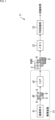
- FIG. 2 is a diagram illustrating an example configuration of an image recognition device based on RGB data.
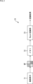
- FIG. 2 is a diagram illustrating an example configuration of an image recognition device based on RAW data.
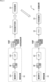
- FIG. 2 is a diagram illustrating learning of the RGB recognition unit in FIG. 1.
- FIG. FIG. 3 is a diagram illustrating learning of the Bayer recognition unit in FIG. 2;
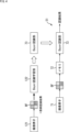
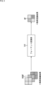
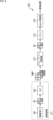
- FIG. 1 is a diagram illustrating an overview of the present disclosure.
- FIG. 1 is a diagram illustrating a configuration example of a preferred embodiment of a learning device of the present disclosure.
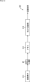
- FIG. 2 is a diagram illustrating the premise of format conversion. It is a figure explaining the example of composition of a learning device.
- FIG. 2 is a diagram illustrating a configuration example of an image recognition device.
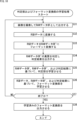
- FIG. 7 is a flowchart illustrating learning processing of a determination unit and a format conversion unit in the learning device of FIG. 6.
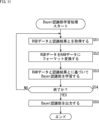
- FIG. 3 is a flowchart illustrating Bayer recognition learning processing.
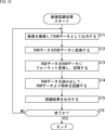
- 10 is a flowchart illustrating image recognition processing by the image recognition device of FIG. 9. It is a figure explaining the modification of an image recognition device.
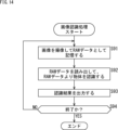
- 14 is a flowchart illustrating image recognition processing by the image recognition device of FIG. 13. It is a figure explaining the modification of a learning device.
- 16 is a flowchart illustrating learning processing by the learning device of FIG. 15.
- FIG. FIG. 2 is a diagram illustrating an application example of the image recognition device.
- FIG. 3 is a diagram illustrating an application example of a format converter.
- FIG. 2 is a diagram illustrating variations in formats in which a pixel block is composed of 2 ⁇ 2 pixels.
- FIG. 2 is a diagram illustrating variations in formats in which a pixel block is composed of 2 ⁇ 2 pixels.
- FIG. 4 is a diagram illustrating variations in formats in which a pixel block is configured with 4 ⁇ 2 pixels.
- FIG. 3 is a diagram illustrating variations in formats in which a pixel block is composed of 3 ⁇ 3 pixels.
- FIG. 3 is a diagram illustrating variations in formats in which a pixel block is composed of 3 ⁇ 3 pixels.
- FIG. 3 is a diagram illustrating variations in formats in which a pixel block is composed of 3 ⁇ 3 pixels.
- FIG. 3 is a diagram illustrating variations in formats in which a pixel block is composed of 3 ⁇ 3 pixels.
- FIG. 3 is a diagram illustrating variations in formats in which a pixel block is composed of 3 ⁇ 3 pixels.
- FIG. 3 is a diagram illustrating variations in formats in which a pixel block is composed of
- FIG. 4 is a diagram illustrating variations in formats in which a pixel block is composed of 4 ⁇ 4 pixels.
- FIG. 4 is a diagram illustrating variations in formats in which a pixel block is composed of 4 ⁇ 4 pixels.
- FIG. 4 is a diagram illustrating variations in formats in which a pixel block is composed of 4 ⁇ 4 pixels.
- FIG. 7 is a diagram illustrating variations in formats composed of pixels of colors in wavelength bands other than RGB pixels.
- FIG. 7 is a diagram illustrating variations in formats composed of pixels of colors in wavelength bands other than RGB pixels.
- FIG. 7 is a diagram illustrating variations in formats composed of pixels of colors in wavelength bands other than RGB pixels.
- FIG. 7 is a diagram illustrating variations in formats composed of pixels of colors in wavelength bands other than RGB pixels.
- FIG. 7 is a diagram illustrating variations in formats composed of pixels of colors in wavelength bands other than RGB pixels.
- FIG. 7 is a diagram illustrating variations in formats composed of pixels of colors in wavelength bands other than RGB pixels.
- FIG. 7 is a diagram illustrating variations in formats composed of pixels of colors in wavelength bands other than RGB pixels.
- FIG. 7 is a diagram illustrating variations in formats composed of pixels of colors in wavelength bands other than RGB pixels.
- FIG. 7 is a diagram illustrating variations in formats composed of pixels of colors in wavelength bands other than RGB pixels.
- FIG. 7 is a diagram illustrating variations in formats composed of pixels of colors in wavelength bands other than RGB pixels.
- An example of the configuration of a general-purpose computer is shown.
- the image recognition device 11 in FIG. 1 includes an imaging device 31, a memory 32, and an RGB recognition section 33.
- the imaging device 31 captures an image to be recognized, and stores RGB data (RGB image) RGBF that is the imaging result in the memory 32.
- the RGB recognition unit 33 is a recognizer such as AI (Artificial Intelligence) consisting of a neural network, which has undergone machine learning based on the RGB data RGBF and the corresponding recognition results. Recognize objects based on AI (Artificial Intelligence)
- the imaging device 31 includes an imaging element 41 and an ISP 42.
- the image sensor 41 is composed of a pixel array in which pixels such as a CMOS (Complementary Metal Oxide Semiconductor) image sensor or a CCD (Charge Coupled Device) image sensor are arranged in an array, and each pixel is used as a unit according to the amount of incident light.
- RAW data BF consisting of pixel signals is generated and output to the ISP 42.
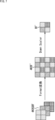
- FIG. 1 shows an example of RAW data BF when a Bayer array color filter is formed on the incident surface of the image sensor 41, and as an example of the arrangement of 2 pixels x 2 pixels, from top to bottom An example of the arrangement of R (red), G (green), G (green), and B (blue) is shown in the direction and from left to right.
- the display of the 2 pixel x 2 pixel arrangement of the RAW data BF will be expressed only by the grid pattern representing each pixel, and the notation of RGGB etc. by leader lines will be omitted.
- the ISP (Image Signal Processor) 42 generates three images, an R image, a G image, and a B image, by performing demosaic processing on each of RGB based on the RAW data BF, and combines them into RGB It is output and stored in the memory 32 as data RGBF.
- the RGB data RGBF is expressed as a collection of 2 pixel x 2 pixel images for each of the G image, R image, and B image from the left in the figure.
- the display of the 2 pixel x 2 pixel arrangement of RGB data RGBF will be expressed only by the grid pattern representing each pixel, and the representation of RGB by leader lines will be omitted.
- each RGB pattern of the grid corresponds to the RAW data BF.
- the RGB data RGBF is data that has been demosaiced for each of RGB based on the RAW data BF, so the amount of data is three times that of the RAW data BF, and at the same time, there is no loss of texture information. Occur.
- the image recognition device 11 is installed in a mobile communication device such as a smartphone, it is possible to save the limited capacity of the memory 32 as much as possible, and to suppress the loss of texture information. In order to improve recognition accuracy, it is desirable to perform recognition processing based on RAW data BF instead of RGB data RGBF.
- an image recognition device that recognizes objects based on RAW data as shown in FIG. 2 is a desirable configuration in terms of saving memory capacity and improving recognition accuracy.
- the image recognition device 51 in FIG. 2 includes an image sensor 71, a memory 72, and a Bayer recognition section 73.
- the image sensor 71, memory 72, and Bayer recognition unit 73 have configurations corresponding to the image sensor 41, memory 32, and RGB recognition unit 33 in FIG. 1, and the image sensor 71 and the image sensor 41 are the same. .
- the image recognition device 51 in FIG. 2 is different from the image recognition device 11 in FIG. The point is that a Bayer recognition section 73 is provided instead of the recognition section 33.
- the Bayer recognition unit 73 is a recognizer such as AI (Artificial Intelligence) consisting of a neural network that has undergone machine learning based on the RAW data BF and the corresponding recognition results. Recognize objects based on AI (Artificial Intelligence)
- the image used for recognition processing is RAW data BF, and the amount of data can be reduced to 1/3 compared to RGB data RGBF, so the amount of memory 72 used can be reduced. It becomes possible to reduce it to 1/3.
- the RGB recognition unit 33 is a recognizer consisting of a neural network that performs machine learning based on the RGB data RGBF and the recognition results that serve as the corresponding teacher data.
- the RGB recognition learning unit 111 combines the RGB data RGBF captured by the imaging device 91 corresponding to the imaging device 31 and the recognition result (teacher recognition result) that becomes the corresponding teacher data.
- the RGB recognition unit 33 is generated by executing the machine learning using the RGB recognition unit 33.
- the imaging device 91 includes an imaging device 101 and an ISP 102, both of which have the same configuration as the imaging device 41 and ISP 42 in the imaging device 31.
- the RGB recognition unit 33 uses RGB data RGBF generated by being imaged by a general imaging device such as the imaging device 31 or 91, and the recognition result (teacher recognition result) that becomes the corresponding teacher data.
- the image recognition device 11 generates the image using machine learning and uses it in the image recognition device 11.
- the Bayer recognition unit 73 is a recognizer consisting of a neural network that performs machine learning based on the RAW data BF and the recognition results (teacher recognition results) serving as the corresponding teacher data.
- the Bayer recognition learning unit 122 combines the RAW data BF captured by the image sensor 121 corresponding to the image sensor 71 and the recognition result (teacher recognition result) that becomes the corresponding teacher data.
- a Bayer recognition unit 73 is generated by executing the machine learning using the above method.
- the image sensor 121 has the same configuration as the image sensor 71.
- the Bayer recognition unit 73 performs image recognition using machine learning that uses the RAW data BF generated by being imaged by the image sensor 121 and recognition results (teacher recognition results) that serve as corresponding teacher data. It is used in the device 51.
- training data that is a set of RGB data RGBF and recognition results (teacher recognition results) that serve as corresponding training data is generally used for training of the recognizer.
- the image recognition device 11 using the recognition unit 33 has a general configuration.
- Some imaging devices can output captured images as RAW data, but training data that is a set of RAW data and recognition results that serve as training data is generally not available. Not widely distributed.
- RGB data RGBF which is generally distributed as learning data
- teacher data The training data consisting of a set of recognition results (teacher recognition results) is format-converted into learning data consisting of a set of RAW data BF and recognition results (teacher recognition results) serving as teacher data.
- the recognition results that serve as training data are information that corresponds to positions within the image, so if RGB data RGBF can be converted to RAW data BF, the recognition results that serve as training data are information that corresponds to the corresponding positions on the image.
- the information can be used as is.
- RGB data RGBF if it is possible to convert RGB data RGBF to RAW data BF, it is possible to convert RGB data RGBF into RAW data BF, which is a set for learning consisting of commonly distributed RGB data RGBF and recognition results as training data (teacher recognition results). Data can be format-converted into learning data consisting of a set of RAW data BF and recognition results (teacher recognition results) serving as teacher data.
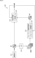
- the learning device 201 in FIG. 6 is composed of a neural network called GAN (Generative Adversarial Network), and includes a format conversion unit 141 and a determination unit that determines the authenticity of the conversion result of the format conversion unit 141. is generated by learning.
- GAN Generic Adversarial Network
- a GAN has a network structure consisting of two networks: a generation network (generator) and a discrimination network (discriminator).
- a generator that generates non-existent data and a converter that transforms data according to the features of existing data are generated by learning.
- the format conversion unit 141 of the present disclosure is generated by learning in a generation network of the GAN that constitutes the learning device 201 in FIG. 6.
- a determination unit that determines the authenticity of a product or a conversion result of a generator or converter that is generated by learning in a generation network (generator) is generated by learning.
- the generator or converter is trained in the generation network so that it can deceive the authenticity judgment of the determination unit generated by the identification network, and the identification network is trained so that it can more accurately identify authenticity.
- the judgment part is trained.
- the two networks in GAN, the discriminator and the generator are generated by adversarially learning generators and converters with contradictory purposes and the determining unit.
- the learning device 201 in FIG. 6 includes an image sensor 211, an ISP 212, a format conversion learning section 213 that causes the format conversion section 221 to learn, and a determination learning section 214 that causes the determination section 231 to learn.
- the image sensor 211 is equipped with a Bayer array color filter, captures an image in the learning data, and outputs it to the ISP 212 and the determination learning unit 214 as Bayer array RAW data BF.
- the ISP212 has a configuration compatible with the ISP42 and 102, and generates three images, an R image, a G image, and a B image, by performing demosaic processing on each of RGB based on the RAW data BF, and are also output to the format conversion learning unit 213 as RGB data RGBF.
- the format conversion learning unit 213 is a generation network (generator) in the GAN, and trains the format conversion unit 221 corresponding to the format conversion unit 141, which converts RGB data RGBF into RAW data BF'.
- RAW data BF' is the conversion result of restoring RGB data RGBF to RAW data BF, but since complete restoration may not be possible with conversion, "'" is used to indicate that they are not completely the same. has been granted.
- the format conversion learning unit 213 performs format conversion based on the RAW data BF′ that is the conversion result of the format conversion unit 221 and the determination result of the determination unit 231 in the determination learning unit 214 based on the corresponding RAW data BF.
- the determination learning unit 214 is a discriminator in the GAN, and uses the RAW data BF' that is the result of format conversion by the format conversion unit 221 and the original RAW data BF supplied from the image sensor 211 to the determination unit 231.
- the format conversion learning unit 213 outputs the determination result to the format conversion learning unit 213.
- the determination learning unit 214 makes a determination based on the RAW data BF' that is the result of format conversion by the format conversion unit 221, the original RAW data BF supplied from the image sensor 211, and the determination result regarding the authenticity of both.
- the section 231 is trained.
- the determination unit 231 compares the RAW data BF and the RAW data BF' to determine authenticity, and the determination learning unit 214 compares the RAW data BF', the RAW data BF, and the determination result of the determination unit 231. , the determination unit 231 is trained to discriminate between RAW data BF and RAW data BF' with high accuracy.
- the format conversion section 221 and the determination section 231 are generated by learning by the learning device 201.
- a training dataset consisting of the widely distributed RGB data RGBF and recognition results (teacher recognition results) that serve as training data is converted into a training dataset consisting of RAW data and recognition results that serve as training data. becomes possible.
- the RAW data of a 4K size image is expressed as RAW data 4KBF
- the 4K size RGB data is expressed as RGB data 4KRGBF
- the image size of the input image is 4K size.
- the format conversion unit 221 converts the 4K size RGB data 4KRGBF, which is generated by demosaicing the RAW data 4KBF, into 4K size RAW data 4KBF', and further downscales the RAW data Output as data BF'.
- the size of the input image and the output image will be expressed in the same way as the size of the output image, and the explanation will proceed without specifically mentioning downscaling, but in reality, The downscaling described above has been done.
- ⁇ Learning device for learning Bayer recognition unit> By using the format conversion unit 221, it is possible to train a Bayer recognition unit that performs image recognition processing based on an image consisting of RAW data from training data consisting of RGB data RGBF and recognition results serving as teacher data. becomes.
- FIG. 8 shows an example of the configuration of a learning device that trains a Bayer recognition unit that performs image recognition processing based on an image consisting of RAW data from learning data consisting of RGB data RGBF and recognition results serving as teacher data. .
- the learning device 251 in FIG. 8 includes a format conversion section 241 and a Bayer recognition learning section 242.
- the format conversion unit 241 has the same configuration as the format conversion unit 221 in FIG. 6, and converts learning data consisting of widely distributed RGB data RGBF and recognition results that will become training data into RAW data and training data. It is converted into learning data consisting of recognition results and output to the Bayer recognition learning section 242.
- the Bayer recognition learning unit 242 is an AI (Artificial Intelligence) consisting of a neural network, etc. that executes image recognition processing based on an image made of RAW data, using learning data of RAW data and recognition results serving as teacher data.
- a Bayer recognition unit 243 is generated by learning.
- Image recognition device that performs image recognition processing based on images consisting of RAW data> Furthermore, by generating the format conversion section 221 and the Bayer recognition section 243, an image recognition device as shown in FIG. 9 is realized.
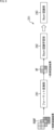
- the image recognition device 261 in FIG. 9 includes an imaging device 271, a format conversion section 272, a memory 273, and a Bayer recognition section 274.
- the imaging device 271 is a general imaging device, and is composed of an imaging device 281 and an ISP 282.
- the image sensor 281 has a configuration corresponding to the image sensor 41, and captures an image and outputs it as RAW data BF.
- the ISP 282 has a configuration corresponding to the ISP 42, and generates RGB data RGBF from the RAW data BF by demosaicing and outputs it as an imaging result.
- the format conversion unit 272 has the same configuration as the format conversion unit 221 in FIG. Store in.
- the Bayer recognition unit 274 is, for example, the Bayer recognition unit 243 generated by the learning process of the learning device 251 in FIG. and outputs the recognition results.
- image recognition processing realized in the present disclosure includes, for example, image-based detection processing and recognition processing of a specific object such as a person or vehicle, semantic segmentation, classification, human skeleton detection processing, and character recognition processing (OCR: Optical Character Recognition).
- OCR Optical Character Recognition
- the memory 273 stores data consisting of the RAW data BF', which is about 1/3 the capacity of the RGB data RGBF, so it is possible to save the capacity of the memory 273. It becomes possible.
- the size of the memory 273 itself can be reduced when considering that the image recognition device 261 is installed in a mobile communication device such as a smartphone. This makes it possible to downsize the device configuration.
- step S31 the image sensor 211 captures an image and outputs it to the ISP 212 and the determination learning unit 214 as Bayer array RAW data BF. Note that this process does not need to be the result of imaging by the image sensor 211, as long as it is possible to obtain an image consisting of new RAW data BF, but it can be performed from RAW data BF that has already been captured by another image sensor, etc. that can be obtained. You may also use an image that looks like this.
- step S32 the ISP 212 converts the RAW data BF into RGB data RGBF by demosaicing and outputs it to the format conversion learning unit 213.
- step S33 the format conversion learning section 213 causes the format conversion section 221 to convert the RGB data RGBF into RAW data BF' and outputs it to the determination learning section 214.
- step S34 the determination learning unit 214 controls the determination unit 231 to compare the RAW data BF from the image sensor 211 and the RAW data BF' from the format conversion learning unit 213, and compares the RAW data BF' from the format conversion learning unit 213. Determine the authenticity and output the determination result.
- step S35 the determination learning unit 214 causes the determination unit 231 to learn based on the RAW data BF, RAW data BF', and the determination result.
- step S36 the format conversion learning section 213 causes the format conversion section 221 to learn based on the RGB data RGBF, RAW data BF', and the determination result.
- step S37 it is determined whether or not termination of learning has been instructed, and if termination has not been instructed, the process returns to step S31 and the subsequent processes are repeated.
- step S37 if the end of learning is instructed, the process proceeds to step S38.
- step S38 the format conversion learning section 213 outputs the learned format conversion section 221.
- the format conversion unit 221 and the determination unit 231 are learned by adversarial learning between the format conversion unit 221 and the determination unit 231 using the RAW data BF, and the format conversion unit 221 is generated and output as a learning result. Ru.
- RGB data RGBF into RAW data BF, which is a learning data set that is a set of RGB data RGBF and recognition results serving as teacher data, which is widely distributed.
- a training data set that is a set of RGB data RGBF and recognition results that serve as training data, which are widely distributed, is converted into a training data set that includes RAW data BF and recognition results that serve as training data. It becomes possible to do so.
- the Bayer recognition unit that recognizes objects can be It becomes possible to easily learn and generate.
- Bayer recognition unit learning process which is the learning process of the Bayer recognition unit 243 by the learning device 251 of FIG. 8, will be described.
- step S51 the format conversion unit 241 acquires a learning data set that includes the unprocessed RGB data RGBF and the recognition results that serve as teacher data.
- step S52 the format conversion unit 241 format-converts the RGB data RGBF into RAW data BF, of the learning data in which the RGB data RGBF and the recognition result as the teacher data are set, and the recognition result as the teacher data. and output it as learning data.
- step S53 the Bayer recognition learning unit 242 causes the Bayer recognition unit 243 to learn based on the learning data consisting of the RAW data BF and the recognition result serving as teacher data.
- step S54 it is determined whether or not termination of learning has been instructed, and if termination has not been instructed, the process returns to step S51 and the subsequent processes are repeated.
- steps S51 to S54 is repeated until the end of learning is instructed, and the learning of the Bayer recognition unit 243 is repeated.
- step S54 when the end of learning is instructed, the process proceeds to step S55.
- step S55 the Bayer recognition learning section 242 outputs the trained Bayer recognition section 243.
- step S71 the imaging device 281 of the imaging device 271 captures an image and outputs it to the ISP 282 as RAW data BF.
- step S72 the ISP 282 converts the RAW data BF into RGB data RGBF by demosaicing each of RGB, and outputs it to the format conversion unit 272 as an imaging result.
- step S73 the format converter 272 converts the RGB data RGBF into RAW data BF and stores it in the memory 273.
- step S74 the Bayer recognition unit 274 reads the stored RAW data BF from the memory 273, performs image recognition processing based on the image made up of the RAW data BF, and recognizes the object.
- step S75 the Bayer recognition unit 274 outputs a recognition result based on the image made of RAW data BF.
- step S76 it is determined whether or not termination of the image recognition process has been instructed, and if termination has not been instructed, the process returns to step S71 and the subsequent processes are repeated.
- the image made of RGB data RGBF captured by the imaging device 271 is format-converted to RAW data, and the image recognition process based on the image made of the format-converted RAW data is repeated until the end is instructed.
- step S76 when an instruction to end is given, the image recognition process is ended.
- the image recognition device 261 of FIG. 9 when assuming a so-called SoC (System on Chip) in which the format conversion section 272, memory 273, and Bayer recognition section 274 are mounted on one chip, the capacity of the memory 273 Since the memory 273 can be saved, the size of the memory 273 can be reduced, and as a result, the size of the chip itself can be reduced.
- SoC System on Chip
- the image recognition device 261 is provided with the imaging device 271, and the imaging result is output as an image consisting of RGB data RGBF. After the conversion, it was necessary to perform image recognition processing in the Bayer recognition unit 274.
- the RAW data BF output from the image sensor 281 may be output as is as an imaging result, and the Bayer recognition unit 274 may perform image recognition processing.
- FIG. 13 shows a configuration example of an image recognition device in which RAW data BF is output as the imaging result and image recognition processing is performed based on the RAW data BF.
- the image recognition device 301 in FIG. 13 differs from the image recognition device 261 in FIG. 9 in that only an image sensor 311 is provided instead of the image pickup device 271, and the format conversion unit 221 is therefore omitted.
- the point is that the RAW data BF is output as is to the memory 312 as the imaging result.
- the image recognition device 301 in FIG. 13 includes an image sensor 311, a memory 312, and a Bayer recognition section 313.
- the image sensor 311, memory 312, and Bayer recognition unit 313 have configurations corresponding to the image sensor 281, memory 273, and Bayer recognition unit 243 in FIG. 8, respectively.
- RAW data BF is output as the imaging result and stored in the memory 312.
- the Bayer recognition unit 313 reads the RAW data BF stored in the memory 312, executes image recognition processing, and outputs the recognition result.
- RAW data BF is no longer converted to RGB data RGBF, texture loss is suppressed, and recognition accuracy in image recognition processing can be improved.
- step S91 the image sensor 311 captures an image and outputs it to the memory 312 for storage as an image capture result consisting of RAW data BF.
- step S92 the Bayer recognition unit 313 reads the RAW data BF from the memory 312, performs recognition processing based on the image made of the RAW data BF, and recognizes the object.
- step S93 the Bayer recognition unit 313 outputs a recognition result based on the image made of the RAW data BF.
- step S94 it is determined whether or not termination of the recognition process has been instructed, and if termination has not been instructed, the process returns to step S91 and the subsequent processes are repeated.
- the image recognition process is repeated based on the image formed from the RAW data BF from the image captured by the image sensor 311 until the end is instructed.
- step S94 when an instruction to end is given, the recognition process is ended.
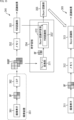
- FIG. 15 shows a configuration example of a learning device in which a Bayer recognition unit 355 (configuration corresponding to the Bayer recognition unit 313) is generated by retraining an existing RGB recognition unit using RAW data BF. ing.
- the learning device 341 in FIG. 15 includes an imaging device 351, a memory 352, an RGB recognition section 353, and a relearning section 354.
- imaging device 351, memory 352, RGB recognition unit 353, and imaging device 361 and ISP 362 in FIG. 15 are the same as the imaging device 31, memory 32, RGB recognition unit 33, and It has the same configuration as the image sensor 41 and the ISP 42.
- the learning device 341 in FIG. 15 differs from the image recognition device 11 in FIG. 1 in that a relearning unit 354 is provided.
- the relearning unit 354 format-converts the RGB data RGBF that is the imaging result of the imaging device 351 into RAW data BF, retrains the trained RGB recognition unit 353 (353') with the RAW data BF, and performs Bayer recognition. 355 is generated. Note that the Bayer recognition unit 355 has a configuration corresponding to the Bayer recognition unit 313 in FIG. 13.
- the relearning section 354 includes a format conversion section 371 and a Bayer recognition learning section 372.
- the format conversion unit 371 has the same configuration as the format conversion unit 221 generated by the learning device 201 in FIG. 6, and converts the RGB data RGBF output as the imaging result of the imaging device 351 into RAW data BF, It is output to the Bayer recognition learning section 372 together with the RGB data RGBF.
- the Bayer recognition learning section 372 uses a trained RGB recognition section 353' that is capable of recognition processing using the same RGB data RGBF as the RGB recognition section 353, and uses the RGB recognition section 353' to perform recognition processing based on the RAW data BF and the RGB data RGBF.
- a Bayer recognition unit 355 capable of image recognition processing is trained using the RAW data BF and output.
- the Bayer recognition learning unit 372 performs image recognition processing on the image recognition result corresponding to the RGB data RGBF with the corresponding RAW data BF.
- a Bayer recognition unit 355 is generated by causing the RGB recognition unit 353 to relearn the results.
- the learned Bayer recognition unit 355 is applied as the Bayer recognition unit 313 in the image recognition device 301 to realize image recognition processing.
- step S101 the format conversion unit 371 of the relearning unit 354 obtains RGB data RGBF that is the imaging result of the imaging device 351.
- step S102 the format conversion unit 371 converts the RGB data RGBF into RAW data BF and outputs it to the Bayer recognition learning unit 372 together with the RGB data RGBF.
- step S103 the Bayer recognition learning section 372 retrains the RGB recognition section 353' based on the RGB data RGBF and the RAW data BF, thereby improving the Bayer recognition section 355 capable of image recognition processing using the RAW data BF. Let them learn.
- step S104 it is determined whether or not termination of learning has been instructed, and if termination has not been instructed, the process returns to step S101 and the subsequent processes are repeated.
- steps S101 to S104 are repeated until the end of learning is instructed, and the relearning by the relearning unit 354 is repeated.
- step S104 the process proceeds to step S105.
- step S105 the Bayer recognition learning section 372 outputs the trained Bayer recognition section 355.
- image recognition devices Although an example has been described above in which the Bayer recognition unit 355 performs image recognition processing from RAW data BF, image recognition processing may be performed using a format different from that of RAW data BF.
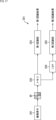
- FIG. 17 shows a configuration example of an image recognition device that implements two different recognition processes from RAW data BF.
- the image recognition device 381 in FIG. 17 includes an image sensor 391, a memory 392, a first recognition section 393, an ISP 394, and a second recognition section 395.
- image sensor 391 and memory 392 have the same functions as the image sensor 311 and memory 312 in the image recognition device 301, so a description thereof will be omitted.
- the first recognition unit 393 is a recognizer such as AI that is made up of a neural network and performs a first recognition process from the RAW data BF stored in the memory 392, and uses the processing result of the first recognition process as the first recognition result. Output.
- AI a recognizer such as AI that is made up of a neural network and performs a first recognition process from the RAW data BF stored in the memory 392, and uses the processing result of the first recognition process as the first recognition result. Output.
- the ISP 394 performs predetermined signal processing on the RAW data BF stored in the memory 392 and outputs the predetermined signal processing result to the second recognition unit 395.
- the ISP 394 is, for example, the ISP 282 of the imaging device 271, and in this case, converts the RGB data into RGBF through demosaic processing and outputs it to the second recognition unit 395.
- the second recognition unit 395 is configured to recognize an AI or the like comprising a neural network that implements a second recognition process different from the first recognition process realized by the first recognition unit 393 based on the signal processing result supplied from the ISP 394. and outputs the processing result of the second recognition process as the second recognition result.
- the second recognition process is a recognition process for a format different from the first recognition process, for example, an image recognition process based on RGB data RGBF. This is image recognition processing.
- the ISP 394 performs signal processing such as format conversion required for the second recognition process on the RAW data BF, and outputs it to the second recognition unit 395.
- the first recognition unit 393 and the second recognition unit 395 can simultaneously perform image recognition processing for different purposes based on the same RAW data.
- the recognition processing of the image recognition device in FIG. 17 is the same as the case where the first recognition unit 393 and the second recognition unit 395 individually perform image recognition processing, so a description thereof will be omitted.
- format conversion section >> In the above, an example has been described in which the format conversion unit 221 converts RGB data RGBF to Bayer format as an example of RAW data, but other formats may be used depending on the type of data in each pixel of the image sensor 281 etc. It may also be converted to RAW data.
- FIG. 18 shows an example of a format conversion unit 401 that includes a neural network that converts RGB data RGBF to RAW data in various formats.
- the format converting unit 401 not only converts RGB data RGBF to RAW data BF consisting of Bayer format BF, but also converts RGB data RGBF into RAW data BF consisting of Bayer format BF.
- a configuration including a neural network that converts to RAW data may also be used.
- the format conversion unit 401 converts the RGB data RGBF into multiple formats such as a multispectral format MSF consisting of pixel values of more colors (bands) than the three RGB colors, a monochrome format MCF consisting of pixel values of two colors (black and white), and a plurality of types.
- the data may be converted into RAW data in various formats, such as a polarization format PF consisting of pixel values of polarized light, or a depth map format DMF consisting of pixel values (distance values) constituting a depth map.
- the format conversion unit 401 can convert RGB data RGBF to RAW data in various formats, so training data that includes RAW data in various formats and recognition results as training data can be created. It becomes possible to generate.
- RAW data converted by the format converter >>
- the format conversion unit 401 converts RGB data RGBF into RAW data in various formats such as multispectral format MSF, monochrome format MCF, polarization format PF, or depth map format DMF. , it may be converted to other RAW data.
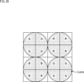
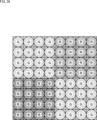
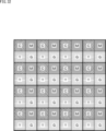
- RAW data include a format (QBC (Quad Bayer coding) format in which each of R pixels, G pixels, and B pixels is composed of pixel blocks of 2 ⁇ 2 pixels, as shown in FIG. 19). ) is also fine.
- QBC Quad Bayer coding
- each pixel is provided with an OCL (On Chip Lens: expressed as "Lens” in the figure) indicated by a circle.
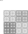
- the OCL may be formed in units of multiple pixels, for example, as shown in FIG. 20, it may be formed in units of pixel blocks of 2 ⁇ 2 pixels.
- FIG. 21 shows a format in which each of R pixels, G pixels, and B pixels is composed of pixel blocks of 4 ⁇ 2 pixels.
- the OCL may be formed, for example, in pixel blocks of 2 ⁇ 1 pixels, or in pixel blocks of 4 ⁇ 2 pixels.
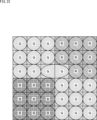
- the format may be such that each of the R pixel, G pixel, and B pixel is composed of a pixel block of 3 ⁇ 3 pixels.
- FIG. 22 shows a format in which each of R pixels, G pixels, and B pixels is composed of pixel blocks of 3 ⁇ 3 pixels.
- the OCL is formed for each pixel, as in the QBC format of FIG. 19, for example.
- the OCL may be formed in units of pixel blocks of 3 ⁇ 3 pixels, for example.
- phase difference detection pixels may be formed.
- the pixels in the third row from the top and the second and third columns from the left are formed so that an elliptical OCL straddles them, and both are in a format consisting of G pixels. There is.
- 3 x 3 pixels + 1 pixel at the top left is set as a pixel block consisting of G pixels
- 3 x 3 pixels - 1 pixel at the top right is set as a pixel block consisting of R pixels, which is used as a pixel block for phase difference detection.
- a pixel block for phase difference detection may be formed by forming OCLs so as to straddle each other as shown by dotted lines.
- a pixel block for phase difference detection may be formed such that an OCL is formed in a range of 2 x 3 pixels in the vertical direction x horizontal direction surrounded by a dotted line. .
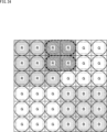
- FIG. 26 shows a format in which each of R pixels, G pixels, and B pixels is composed of pixel blocks of 4 ⁇ 4 pixels.
- the OCL is formed using each pixel as a unit, as in the case of the format of FIG. 19, for example.
- the OCL may be formed of pixel blocks each having a unit of 2 ⁇ 2 pixels, for example.
- the pixel block may be formed as a unit of 4 ⁇ 4 pixels.
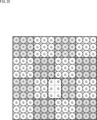
- FIG. 27 which is composed of pixel blocks with 4 ⁇ 4 pixels as units, it is possible to create a format suitable for various uses by switching binning in remosaic performed by signal processing. .
- each pixel is remosaiced (array conversion processing) as an R pixel, a G pixel, and a B pixel. You can do it like this.
- binning is performed in units of 2 ⁇ 2 pixels, and each unit is divided into R pixels, G pixels, and B pixels.
- Remosaic may be performed to form pixel blocks.
- binning is performed using 4 ⁇ 4 pixels as a unit, and each unit is divided into R pixels, G pixels, and B pixels. Remosaic may be performed to form pixel blocks.
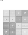
- the unit is 2 ⁇ 2 pixels, and consists of an R pixel block consisting of an R pixel and a W (white) pixel, a G pixel block consisting of a G pixel and a W pixel, and a B pixel and a W pixel. It is also possible to use a format in which B pixel blocks are configured and RGB pixel blocks are arranged in a Bayer array. In this case, the W pixels in each pixel block are arranged in a checkerboard pattern. Sensitivity is improved by the configuration in which W pixels are used in this way.
- complementary color (Cyan, Magenta, Yellow) pixels may be used instead of the W pixel in FIG. 29.
- a G pixel block consists of G pixels and Ye (Yellow) pixels
- an R pixel block consists of R pixels and M (Magenta) pixels
- a B pixel block consists of B pixels and Cy (Cyan) pixels. It may also be configured such that the RGB pixel blocks are arranged in a Bayer array. In this case, complementary color pixels in each pixel block are arranged in a checkerboard pattern. Color reproducibility is improved by the configuration in which complementary color pixels are used in this manner.
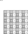
- a format may be used in which the unit is 2 ⁇ 2 pixels and is composed of pixel blocks consisting of RGB pixels and W (white) pixels.
- IR (infrared light) pixels may be arranged instead of W pixels.
- Y (Yellow) pixels may be arranged instead of W pixels.
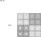
- a format may be used in which the unit is 2 ⁇ 2 pixels and is composed of pixel blocks consisting of Y (Yellow) pixels, M (Magenta) pixels, C (Cyan) pixels, and G pixels. .
- the unit is 2 ⁇ 2 pixels, and there are two pixel blocks consisting of Y (Yellow) pixels, a pixel block consisting of M (Magenta) pixels, and a pixel block consisting of C (Cyan) pixels. It may also be a format composed of: In the case of FIG. 33, pixel blocks consisting of two Y (Yellow) pixels are arranged in a checkered pattern.
- the units are 2 ⁇ 2 pixels, and there are pixel blocks consisting of Y (Yellow) pixels, pixel blocks consisting of M (Magenta) pixels, pixel blocks consisting of C (Cyan) pixels, and G
- the format may be composed of pixel blocks made up of pixels.
- one of the two pixel blocks consisting of Y (Yellow) pixels in FIG. 33 is arranged as a pixel block consisting of G pixels.
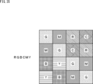
- the unit is 2 ⁇ 2 pixels, and there are two pixel blocks consisting of G pixels and M pixels, a pixel block consisting of R pixels and C pixels, and a pixel block consisting of B pixels and Y pixels.
- a format composed of pixel blocks may also be used.
- two pixel blocks consisting of G pixels and M pixels are defined as a G pixel block
- a pixel block consisting of R pixels and C pixels is defined as an R pixel block
- a pixel block consisting of B pixels and Y pixels It is assumed to be a B pixel block and a Bayer array of RGB pixel blocks. Further, the pixels of two colors forming each pixel block are arranged in a checkerboard pattern.
- the 2 ⁇ 2 pixel unit is composed of two pixel blocks consisting of Y pixels, a pixel block consisting of R pixels, and a pixel block consisting of C pixels.
- two pixel blocks consisting of Y pixels are assumed to be a G pixel block
- a pixel block consisting of R pixels is assumed to be an R pixel block
- a B pixel block consisting of C pixels is assumed to be an RGB pixel block. It is assumed to be a Bayer array.
- Example of execution using software can be executed by hardware, but can also be executed by software.
- the programs that make up the software can execute various functions by using a computer built into dedicated hardware or by installing various programs. It is installed from a recording medium onto a computer that can be used, for example, a general-purpose computer.
- FIG. 37 shows an example of the configuration of a general-purpose computer.
- This computer has a built-in CPU (Central Processing Unit) 1001.
- An input/output interface 1005 is connected to the CPU 1001 via a bus 1004.
- a ROM (Read Only Memory) 1002 and a RAM (Random Access Memory) 1003 are connected to the bus 1004 .
- the input/output interface 1005 includes an input unit 1006 consisting of input devices such as a keyboard and mouse for inputting operation commands by the user, an output unit 1007 for outputting processing operation screens and images of processing results to a display device, and an output unit 1007 for outputting programs and various data.
- a storage unit 1008 consisting of a hard disk drive for storing data
- a communication unit 1009 consisting of a LAN (Local Area Network) adapter, etc., and executing communication processing via a network typified by the Internet are connected.
- LAN Local Area Network
- magnetic disks including flexible disks
- optical disks including CD-ROM (Compact Disc-Read Only Memory), DVD (Digital Versatile Disc)), magneto-optical disks (including MD (Mini Disc)), or semiconductor
- a drive 1010 that reads and writes data to and from a removable storage medium 1011 such as a memory is connected.
- the CPU 1001 executes programs stored in the ROM 1002 or read from a removable storage medium 1011 such as a magnetic disk, optical disk, magneto-optical disk, or semiconductor memory, installed in the storage unit 1008, and loaded from the storage unit 1008 into the RAM 1003. Execute various processes according to the programmed program.
- the RAM 1003 also appropriately stores data necessary for the CPU 1001 to execute various processes.
- the CPU 1001 executes the above-described series by, for example, loading a program stored in the storage unit 1008 into the RAM 1003 via the input/output interface 1005 and the bus 1004 and executing it. processing is performed.
- a program executed by the computer (CPU 1001) can be provided by being recorded on a removable storage medium 1011 such as a package medium, for example. Additionally, programs may be provided via wired or wireless transmission media, such as local area networks, the Internet, and digital satellite broadcasts.
- a program can be installed in the storage unit 1008 via the input/output interface 1005 by attaching the removable storage medium 1011 to the drive 1010. Further, the program can be received by the communication unit 1009 via a wired or wireless transmission medium and installed in the storage unit 1008. Other programs can be installed in the ROM 1002 or the storage unit 1008 in advance.
- the program executed by the computer may be a program in which processing is performed chronologically in accordance with the order described in this specification, in parallel, or at necessary timing such as when a call is made. It may also be a program that performs processing.
- the CPU 1001 in FIG. 37 is the learning device 201 in FIG. 6, the learning device 251 in FIG. 8, the image recognition device 261 in FIG. 9, the image recognition device 301 in FIG. 13, the learning device 341 in FIG. 15, and the image recognition device in FIG.
- the device 381 realizes the function of the format converter 401 in FIG.
- a system refers to a collection of multiple components (devices, modules (components), etc.), regardless of whether all the components are located in the same casing. Therefore, multiple devices housed in separate casings and connected via a network, and a single device with multiple modules housed in one casing are both systems. .
- the present disclosure can take a cloud computing configuration in which one function is shared and jointly processed by multiple devices via a network.
- each step described in the above flowchart can be executed by one device or can be shared and executed by multiple devices.
- one step includes multiple processes
- the multiple processes included in that one step can be executed by one device or can be shared and executed by multiple devices.
- ⁇ 1> An image processing device equipped with a format conversion unit that converts RGB data to RAW data.
- the format conversion unit is generated by adversarial learning with a determination unit that determines the authenticity of the RAW data before being converted to the RGB data and the RAW data converted from the RGB data.
- ⁇ 3> The image processing device according to ⁇ 1> or ⁇ 2>, wherein the format conversion unit converts the RGB data into the RAW data, and then downscales the converted RAW data.
- the format conversion unit converts the learning data consisting of the RGB data and the teacher recognition result into the learning data consisting of the RAW data and the teacher recognition result. Any one of ⁇ 1> to ⁇ 3>.
- the imaging device includes: an image sensor that captures the image and outputs it as the RAW data;
- the image processing device according to ⁇ 6> further comprising a signal processing unit that performs demosaic processing on the RAW data output from the image sensor, converts it into the RGB data, and outputs the RGB data.
- ⁇ 8> Further including an image sensor that captures the image and outputs the image as the RAW data,
- a trained RGB recognition unit that performs image recognition processing on an image made of RGB data is retrained using the RAW data whose format has been converted from the RGB data by the format conversion unit.
- the image processing device according to any one of ⁇ 1> to ⁇ 3>, further including a RAW data recognition unit that performs image recognition processing on an image made of the RAW data.
- a RAW data recognition unit that performs image recognition processing on an image made of the RAW data.
- the RAW data is in a Bayer format, a multispectral format, a monochrome format, a polarization format, or a depth map format.
- An image processing method including the step of converting RGB data to RAW data.
- An image processing device including a RAW data recognition unit that performs image recognition processing based on an image made of RAW data.
- the RAW data recognition unit is generated by learning based on learning data consisting of the RAW data and teacher recognition results,
- the image processing device according to ⁇ 13>, wherein the learning data including the RAW data and the teacher recognition result is training data that is format-converted from the learning data including RGB data and the teacher recognition result.
- the RAW data recognition unit retrains a trained RGB recognition unit that performs image recognition processing on an image made of RGB data using the RAW data generated by format conversion from the RGB data.
- the image processing device according to ⁇ 13>.
- a signal processing unit that performs predetermined signal processing on the RAW data and converts it into another format;
- the image processing device according to ⁇ 13>, further comprising another data recognition unit that performs image recognition processing on the image in the other format converted by the signal processing unit.
- An image processing method including the step of performing image recognition processing based on an image made of RAW data.
- a program that causes a computer to function as a RAW data recognition unit that performs image recognition processing based on images made of RAW data.
- An image recognition unit that receives image data corresponding to a first array of images according to the array of a pixel array made up of an image sensor, performs image recognition processing on the image data, and outputs a recognition processing result.
- the image recognition unit is trained using image data corresponding to images in the first array generated by converting images in a second array different from the first array.
- An image recognition unit that receives image data corresponding to a first array of images according to the array of a pixel array including an image sensor, performs image recognition processing on the image data, and outputs a recognition processing result.
- an image processing method for an image processing device equipped with The image recognition unit is configured to perform learning of the image recognition process using image data corresponding to the images in the first array generated by converting images in a second array different from the first array.
- the image processing method includes the step of performing the image recognition process on the image data and outputting a recognition process result.
- the image formed from the other arrangement is used for learning by an image recognition unit used in image inference processing based on the image formed from the other arrangement.
- the image formed from the other array is used for learning by an image recognition unit used in image inference processing based on the image formed from the other array.
- An image conversion unit that converts an input image in a first array into an image in a second array different from the first array and outputs the image
- An AI network generation device comprising: an AI network learning unit that generates a trained AI network by learning an AI network using the second array of images output from the image conversion unit.
- An AI network generation method comprising the step of generating a trained AI network by learning an AI network using the outputted second array of images.
Landscapes
- Engineering & Computer Science (AREA)
- Physics & Mathematics (AREA)
- General Physics & Mathematics (AREA)
- Theoretical Computer Science (AREA)
- Artificial Intelligence (AREA)
- Evolutionary Computation (AREA)
- Multimedia (AREA)
- Signal Processing (AREA)
- Computer Vision & Pattern Recognition (AREA)
- Image Analysis (AREA)
- Image Processing (AREA)
Priority Applications (2)
| Application Number | Priority Date | Filing Date | Title |
|---|---|---|---|
| JP2024512541A JPWO2023190473A1 (cg-RX-API-DMAC7.html) | 2022-03-28 | 2023-03-28 | |
| US18/845,432 US20250191233A1 (en) | 2022-03-28 | 2023-03-28 | Image processing apparatus, image processing method, image conversion apparatus, image conversion method, ai network generation apparatus, ai network generation method, and program |
Applications Claiming Priority (2)
| Application Number | Priority Date | Filing Date | Title |
|---|---|---|---|
| JP2022051100 | 2022-03-28 | ||
| JP2022-051100 | 2022-03-28 |
Publications (1)
| Publication Number | Publication Date |
|---|---|
| WO2023190473A1 true WO2023190473A1 (ja) | 2023-10-05 |
Family
ID=88202506
Family Applications (1)
| Application Number | Title | Priority Date | Filing Date |
|---|---|---|---|
| PCT/JP2023/012430 Ceased WO2023190473A1 (ja) | 2022-03-28 | 2023-03-28 | 画像処理装置および画像処理方法、画像変換装置および画像変換方法、aiネットワーク生成装置およびaiネットワーク生成方法、並びにプログラム |
Country Status (3)
| Country | Link |
|---|---|
| US (1) | US20250191233A1 (cg-RX-API-DMAC7.html) |
| JP (1) | JPWO2023190473A1 (cg-RX-API-DMAC7.html) |
| WO (1) | WO2023190473A1 (cg-RX-API-DMAC7.html) |
Families Citing this family (1)
| Publication number | Priority date | Publication date | Assignee | Title |
|---|---|---|---|---|
| CN121391950A (zh) * | 2025-10-14 | 2026-01-23 | 深圳元戎启行科技有限公司 | 样本生成方法、网络模型的训练方法及相关装置 |
Citations (5)
| Publication number | Priority date | Publication date | Assignee | Title |
|---|---|---|---|---|
| JP2019029750A (ja) * | 2017-07-27 | 2019-02-21 | 株式会社Jvcケンウッド | 撮像装置 |
| JP2021036646A (ja) * | 2019-08-30 | 2021-03-04 | 株式会社Jvcケンウッド | 情報収集システム、カメラ端末装置、情報収集方法および情報収集プログラム |
| US20210158096A1 (en) * | 2019-11-27 | 2021-05-27 | Pavel Sinha | Systems and methods for performing direct conversion of image sensor data to image analytics |
| JP2021189527A (ja) * | 2020-05-26 | 2021-12-13 | キヤノン株式会社 | 情報処理装置、情報処理方法及びプログラム |
| JP2021197136A (ja) * | 2020-06-10 | 2021-12-27 | インテル コーポレイション | 適応スーパーサンプリングのための深層学習ベースのサンプル選択 |
Family Cites Families (4)
| Publication number | Priority date | Publication date | Assignee | Title |
|---|---|---|---|---|
| US8537240B2 (en) * | 2009-09-29 | 2013-09-17 | Hewlett-Packard Development Company, L.P. | White balance correction in a captured digital image |
| US9025867B2 (en) * | 2012-05-31 | 2015-05-05 | Apple Inc. | Systems and methods for YCC image processing |
| CN114187185B (zh) * | 2020-09-14 | 2026-03-27 | 华为技术有限公司 | 一种数据处理方法、系统及装置 |
| JP7772054B2 (ja) * | 2021-03-15 | 2025-11-18 | ソニーグループ株式会社 | 画像処理装置、画像処理方法、プログラム |
-
2023
- 2023-03-28 JP JP2024512541A patent/JPWO2023190473A1/ja active Pending
- 2023-03-28 WO PCT/JP2023/012430 patent/WO2023190473A1/ja not_active Ceased
- 2023-03-28 US US18/845,432 patent/US20250191233A1/en active Pending
Patent Citations (5)
| Publication number | Priority date | Publication date | Assignee | Title |
|---|---|---|---|---|
| JP2019029750A (ja) * | 2017-07-27 | 2019-02-21 | 株式会社Jvcケンウッド | 撮像装置 |
| JP2021036646A (ja) * | 2019-08-30 | 2021-03-04 | 株式会社Jvcケンウッド | 情報収集システム、カメラ端末装置、情報収集方法および情報収集プログラム |
| US20210158096A1 (en) * | 2019-11-27 | 2021-05-27 | Pavel Sinha | Systems and methods for performing direct conversion of image sensor data to image analytics |
| JP2021189527A (ja) * | 2020-05-26 | 2021-12-13 | キヤノン株式会社 | 情報処理装置、情報処理方法及びプログラム |
| JP2021197136A (ja) * | 2020-06-10 | 2021-12-27 | インテル コーポレイション | 適応スーパーサンプリングのための深層学習ベースのサンプル選択 |
Also Published As
| Publication number | Publication date |
|---|---|
| JPWO2023190473A1 (cg-RX-API-DMAC7.html) | 2023-10-05 |
| US20250191233A1 (en) | 2025-06-12 |
Similar Documents
| Publication | Publication Date | Title |
|---|---|---|
| US12198387B2 (en) | Application processor including neural processing unit and operating method thereof | |
| EP3706042B1 (en) | Image processing method, image processing apparatus, program, image processing system, and manufacturing method of learnt model | |
| US7986352B2 (en) | Image generation system including a plurality of light receiving elements and for correcting image data using a spatial high frequency component, image generation method for correcting image data using a spatial high frequency component, and computer-readable recording medium having a program for performing the same | |
| US9025871B2 (en) | Image processing apparatus and method of providing high sensitive color images | |
| JP5280448B2 (ja) | 画像処理装置、画像処理方法、画像処理プログラム及び半導体集積回路 | |
| KR20240035992A (ko) | 현저성에 기초한 초해상도 | |
| CN113676629B (zh) | 图像传感器、图像采集装置、图像处理方法及图像处理器 | |
| CN102713972A (zh) | 使用神经网络的像素信息再现 | |
| US20240087086A1 (en) | Image processing method, image processing apparatus, program, trained machine learning model production method, processing apparatus, and image processing system | |
| CN114125319A (zh) | 图像传感器、摄像模组、图像处理方法、装置和电子设备 | |
| CN115393193B (zh) | 图像处理方法、图像处理装置及芯片 | |
| KR20240104591A (ko) | 고해상도의 디지털 줌 영상을 생성하는 방법 및 장치 | |
| JP4375322B2 (ja) | 画像処理装置、画像処理方法、そのプログラム、およびそのプログラムを記録したコンピュータ読取り可能な記録媒体 | |
| JP6628987B2 (ja) | 画像処理装置、画像処理方法及び撮像装置 | |
| KR102389304B1 (ko) | 주변 영역을 고려한 이미지 인페인팅 방법 및 디바이스 | |
| KR102389284B1 (ko) | 인공지능 기반 이미지 인페인팅 방법 및 디바이스 | |
| US8441543B2 (en) | Image processing apparatus, image processing method, and computer program | |
| US20250191233A1 (en) | Image processing apparatus, image processing method, image conversion apparatus, image conversion method, ai network generation apparatus, ai network generation method, and program | |
| CN113781350B (zh) | 图像处理方法、图像处理装置、电子设备及存储介质 | |
| US8223231B2 (en) | Imaging apparatus and image processing program | |
| TW202529030A (zh) | 具影像感測器信號處理的方法與裝置以及相關儲存媒體 | |
| JP6696596B2 (ja) | 画像処理システム、撮像装置、画像処理方法およびプログラム | |
| CN115170929A (zh) | 数据处理方法、图像处理系统的训练方法及电子设备 | |
| KR20220081532A (ko) | 이미지 시그널 프로세서 및 이미지 처리 시스템 | |
| US20100296734A1 (en) | Identifying and clustering blobs in a raster image |
Legal Events
| Date | Code | Title | Description |
|---|---|---|---|
| 121 | Ep: the epo has been informed by wipo that ep was designated in this application |
Ref document number: 23780482 Country of ref document: EP Kind code of ref document: A1 |
|
| ENP | Entry into the national phase |
Ref document number: 2024512541 Country of ref document: JP Kind code of ref document: A |
|
| WWE | Wipo information: entry into national phase |
Ref document number: 18845432 Country of ref document: US |
|
| NENP | Non-entry into the national phase |
Ref country code: DE |
|
| 122 | Ep: pct application non-entry in european phase |
Ref document number: 23780482 Country of ref document: EP Kind code of ref document: A1 |
|
| WWP | Wipo information: published in national office |
Ref document number: 18845432 Country of ref document: US |