WO2023189458A1 - 測距モジュール - Google Patents
測距モジュール Download PDFInfo
- Publication number
- WO2023189458A1 WO2023189458A1 PCT/JP2023/009512 JP2023009512W WO2023189458A1 WO 2023189458 A1 WO2023189458 A1 WO 2023189458A1 JP 2023009512 W JP2023009512 W JP 2023009512W WO 2023189458 A1 WO2023189458 A1 WO 2023189458A1
- Authority
- WO
- WIPO (PCT)
- Prior art keywords
- light emitting
- emitting devices
- imaging device
- module according
- pair
- Prior art date
- Legal status (The legal status is an assumption and is not a legal conclusion. Google has not performed a legal analysis and makes no representation as to the accuracy of the status listed.)
- Ceased
Links
Images



Classifications
-
- G—PHYSICS
- G01—MEASURING; TESTING
- G01S—RADIO DIRECTION-FINDING; RADIO NAVIGATION; DETERMINING DISTANCE OR VELOCITY BY USE OF RADIO WAVES; LOCATING OR PRESENCE-DETECTING BY USE OF THE REFLECTION OR RERADIATION OF RADIO WAVES; ANALOGOUS ARRANGEMENTS USING OTHER WAVES
- G01S17/00—Systems using the reflection or reradiation of electromagnetic waves other than radio waves, e.g. lidar systems
- G01S17/86—Combinations of lidar systems with systems other than lidar, radar or sonar, e.g. with direction finders
-
- G—PHYSICS
- G01—MEASURING; TESTING
- G01C—MEASURING DISTANCES, LEVELS OR BEARINGS; SURVEYING; NAVIGATION; GYROSCOPIC INSTRUMENTS; PHOTOGRAMMETRY OR VIDEOGRAMMETRY
- G01C3/00—Measuring distances in line of sight; Optical rangefinders
- G01C3/02—Details
- G01C3/06—Use of electric means to obtain final indication
-
- G—PHYSICS
- G01—MEASURING; TESTING
- G01S—RADIO DIRECTION-FINDING; RADIO NAVIGATION; DETERMINING DISTANCE OR VELOCITY BY USE OF RADIO WAVES; LOCATING OR PRESENCE-DETECTING BY USE OF THE REFLECTION OR RERADIATION OF RADIO WAVES; ANALOGOUS ARRANGEMENTS USING OTHER WAVES
- G01S17/00—Systems using the reflection or reradiation of electromagnetic waves other than radio waves, e.g. lidar systems
- G01S17/02—Systems using the reflection of electromagnetic waves other than radio waves
- G01S17/06—Systems determining position data of a target
- G01S17/08—Systems determining position data of a target for measuring distance only
-
- G—PHYSICS
- G01—MEASURING; TESTING
- G01S—RADIO DIRECTION-FINDING; RADIO NAVIGATION; DETERMINING DISTANCE OR VELOCITY BY USE OF RADIO WAVES; LOCATING OR PRESENCE-DETECTING BY USE OF THE REFLECTION OR RERADIATION OF RADIO WAVES; ANALOGOUS ARRANGEMENTS USING OTHER WAVES
- G01S17/00—Systems using the reflection or reradiation of electromagnetic waves other than radio waves, e.g. lidar systems
- G01S17/88—Lidar systems specially adapted for specific applications
- G01S17/89—Lidar systems specially adapted for specific applications for mapping or imaging
-
- G—PHYSICS
- G01—MEASURING; TESTING
- G01S—RADIO DIRECTION-FINDING; RADIO NAVIGATION; DETERMINING DISTANCE OR VELOCITY BY USE OF RADIO WAVES; LOCATING OR PRESENCE-DETECTING BY USE OF THE REFLECTION OR RERADIATION OF RADIO WAVES; ANALOGOUS ARRANGEMENTS USING OTHER WAVES
- G01S17/00—Systems using the reflection or reradiation of electromagnetic waves other than radio waves, e.g. lidar systems
- G01S17/88—Lidar systems specially adapted for specific applications
- G01S17/89—Lidar systems specially adapted for specific applications for mapping or imaging
- G01S17/894—Three-dimensional [3D] imaging with simultaneous measurement of time-of-flight at a two-dimensional [2D] array of receiver pixels, e.g. time-of-flight cameras or flash lidar
-
- G—PHYSICS
- G01—MEASURING; TESTING
- G01S—RADIO DIRECTION-FINDING; RADIO NAVIGATION; DETERMINING DISTANCE OR VELOCITY BY USE OF RADIO WAVES; LOCATING OR PRESENCE-DETECTING BY USE OF THE REFLECTION OR RERADIATION OF RADIO WAVES; ANALOGOUS ARRANGEMENTS USING OTHER WAVES
- G01S7/00—Details of systems according to groups G01S13/00, G01S15/00, G01S17/00
- G01S7/48—Details of systems according to groups G01S13/00, G01S15/00, G01S17/00 of systems according to group G01S17/00
- G01S7/481—Constructional features, e.g. arrangements of optical elements
-
- G—PHYSICS
- G01—MEASURING; TESTING
- G01S—RADIO DIRECTION-FINDING; RADIO NAVIGATION; DETERMINING DISTANCE OR VELOCITY BY USE OF RADIO WAVES; LOCATING OR PRESENCE-DETECTING BY USE OF THE REFLECTION OR RERADIATION OF RADIO WAVES; ANALOGOUS ARRANGEMENTS USING OTHER WAVES
- G01S7/00—Details of systems according to groups G01S13/00, G01S15/00, G01S17/00
- G01S7/48—Details of systems according to groups G01S13/00, G01S15/00, G01S17/00 of systems according to group G01S17/00
- G01S7/481—Constructional features, e.g. arrangements of optical elements
- G01S7/4811—Constructional features, e.g. arrangements of optical elements common to transmitter and receiver
- G01S7/4813—Housing arrangements
-
- G—PHYSICS
- G01—MEASURING; TESTING
- G01S—RADIO DIRECTION-FINDING; RADIO NAVIGATION; DETERMINING DISTANCE OR VELOCITY BY USE OF RADIO WAVES; LOCATING OR PRESENCE-DETECTING BY USE OF THE REFLECTION OR RERADIATION OF RADIO WAVES; ANALOGOUS ARRANGEMENTS USING OTHER WAVES
- G01S7/00—Details of systems according to groups G01S13/00, G01S15/00, G01S17/00
- G01S7/48—Details of systems according to groups G01S13/00, G01S15/00, G01S17/00 of systems according to group G01S17/00
- G01S7/481—Constructional features, e.g. arrangements of optical elements
- G01S7/4814—Constructional features, e.g. arrangements of optical elements of transmitters alone
- G01S7/4815—Constructional features, e.g. arrangements of optical elements of transmitters alone using multiple transmitters
Definitions
- the present disclosure relates to a distance measurement module, and particularly relates to a distance measurement module that can achieve both wide-angle distance measurement and miniaturization of the device.
- the ToF (Time of Flight) method As a method for measuring the distance to an object and obtaining a distance image, the ToF (Time of Flight) method is known, which measures the distance by the flight time it takes for the irradiated light to reflect off the object and return.
- Patent Document 1 discloses an omnidirectional ranging device that covers a wide detection range by arranging ToF sensors radially close to each other around a central axis.
- the present disclosure has been made in view of this situation, and is intended to make it possible to achieve both wide-angle distance measurement and miniaturization of the device.
- a distance measurement module includes a plurality of light emitting devices that emit irradiation light toward a distance measurement object, and an imaging device that images reflected light that is reflected by the irradiation light on the distance measurement object, and includes a plurality of
- the light emitting device is a distance measuring module arranged at a position and angle such that a composite irradiation range including an overlapping portion of irradiation ranges of the respective irradiation lights includes an imaging range of the imaging device.
- a distance measurement module including a plurality of light emitting devices that emit irradiation light toward a distance measurement object, and an imaging device that captures an image of reflected light that is reflected by the irradiation light on the distance measurement object
- a distance measurement module that includes a plurality of The light emitting devices are arranged at positions and angles such that a composite irradiation range including an overlapping portion of irradiation ranges of the respective irradiation lights includes an imaging range of the imaging device.
- FIG. 2 is a diagram illustrating a configuration example of a conventional ranging module.
- FIG. 3 is a diagram illustrating a configuration example of a ranging module according to the first embodiment.
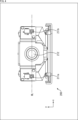
- FIG. 1 is a perspective view showing a configuration example of a ToF camera according to a first embodiment. 1 is a front view showing a configuration example of a ToF camera according to a first embodiment;
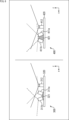
- FIG. 2 is a diagram illustrating the positional relationship between an LD and a camera in a ToF camera. It is a figure showing the example of composition of the ranging module of a 2nd embodiment. It is a figure showing the example of composition of the ranging module of a 3rd embodiment.
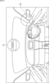
- FIG. 3 is a diagram illustrating an example of application of a distance measurement module.
- First embodiment (configuration having a housing frame as a support structure) 3.
- Second embodiment (configuration having a support substrate as a support structure) 4.
- Third embodiment (configuration that realizes wide-angle distance measurement in the vertical direction) 5.
- Application example
- FIG. 1 is a diagram showing an example of the configuration of a conventional ranging module.
- the ranging modules 10A, 10B, and 10C shown in FIG. 1 all constitute a ToF (Time Of Flight) camera that can measure three-dimensional information using the flight time of light.
- ToF Time Of Flight
- the distance measurement modules 10A, 10B, and 10C use the ToF method to irradiate light from a light-emitting device such as an LED (Light-Emitting Diode) or LD (Laser Diode) to a distance measurement target, and use the reflected light from an imaging device ( The distance to the target object is measured using the time difference between detection by the camera.
- a light-emitting device such as an LED (Light-Emitting Diode) or LD (Laser Diode)
- the ranging module 10A includes a light emitting device 11 and an imaging device 12.
- the light emitting device 11 is arranged so that its light emitting direction is in the same direction as the imaging direction (light receiving direction) of the imaging device 12.
- the light emitting device 11 emits irradiation light toward the distance measurement target, and the imaging device 12 images the reflected light that is the irradiation light emitted by the light emitting device 11 and reflected by the distance measurement target.
- the distance measurement module 10A is configured such that the imaging range 12R of the imaging device 12 is included in the irradiation range 11R of the irradiation light, thereby being able to obtain a distance image of the object to be measured.
- the imaging range of an imaging device can be widened by using a wide-angle lens with an angle of view of 160°, for example.
- the upper limit of the light emission angle that determines the irradiation range of the light emitting device was about 140°. Therefore, the imaging range of the imaging device is also limited to about 140°, and there is a limit to realizing wider-angle distance measurement in the distance measurement module 10A.
- the ranging module 10B includes a pair of a light emitting device 11a and an imaging device 12a, and a pair of a light emitting device 11b and an imaging device 12b.
- the distance measurement module 10B is configured such that the imaging range 12Ra of the imaging device 12a is included in the irradiation range 11Ra of the light emitting device 11a, and the imaging range 12Rb of the imaging device 12b is included in the irradiation range 11Rb of the light emitting device 11b. . Furthermore, in the ranging module 10B, the imaging device 12a and the imaging device 12b are arranged so that a portion of their respective imaging ranges 12Ra and 12Rb overlap with each other.
- the ranging module 10C includes a pair of light emitting devices 11c and 11d and an imaging device 12.
- the light emitting devices 11c and 11d are arranged with the imaging device 12 in between, such that the light emitting direction of each of the light emitting devices 11c and 11d is directed in the same direction as the imaging direction (light receiving direction) of the imaging device 12.
- the distance measurement module 10C is configured such that the imaging range 12R of the imaging device 12 is wider than that of the distance measurement module 10A by using a wide-angle lens with a view angle of 160°, for example.
- the irradiation range 11Rcd is significantly different from the irradiation range when each device is used alone, since the light emitting directions of each device are arranged in the same direction. do not have. Therefore, there is a limit to realizing wide-angle distance measurement even in the distance measurement module 10C.
- a ranging module that can achieve both wide-angle ranging and miniaturization of the device. Specifically, it includes a plurality of light emitting devices and one imaging device, and the plurality of light emitting devices are positioned such that a composite irradiation range including an overlapping portion of the irradiation ranges of the respective irradiation lights includes the imaging range of the imaging device.
- a ranging module located at and range.
- FIG. 2 is a diagram illustrating a configuration example of a ranging module according to the first embodiment to which the technology according to the present disclosure is applied.
- the distance measurement module 100 uses the ToF method to irradiate light from a light-emitting device such as an LED or LD onto a distance measurement target, and uses the time difference until the reflected light is detected by an imaging device to reach the distance measurement target. Measure the distance.
- the ToF method used in the ranging module 100 may be a Direct ToF (dToF) method that simply measures the time difference until the reflected light is detected, or a Direct ToF (dToF) method that accumulates the reflected light and detects the phase difference with the emitted light.
- dToF Direct ToF
- iToF indirect ToF
- the ranging module 100 shown in FIG. 2 includes a pair of light emitting devices 111a and 111b and an imaging device 112.
- the light emitting devices 111a and 111b are composed of LEDs, LDs, and the like, and emit light to irradiate the object to be measured.
- the imaging device 112 is configured with a camera having one or more lenses and an imaging element, and images the reflected light of the irradiation light emitted by the light emitting devices 111a and 111b reflected on the object to be measured.
- the lens included in the imaging device 112 is a wide-angle lens having an angle of view of 140° or more, for example, 160°.
- the x-axis and y-axis are defined as two mutually orthogonal axes in a plane perpendicular to the optical axis direction of the lens included in the imaging device 112, and the z-axis is defined as the optical axis direction of the lens included in the imaging device 112. . It is assumed that the imaging surface of the imaging device 112 is on the xy plane.
- the light emitting devices 111a and 111b are arranged at positions and angles such that a composite irradiation range including an overlapping portion of the irradiation ranges 111Ra and 111Rb of the respective irradiation lights includes the imaging range 112R of the imaging device 112. Ru.
- the light emitting devices 111a and 111b are arranged so that the imaging device 112 is sandwiched between them so that their respective light emitting directions are inclined with respect to the optical axis of the lens included in the imaging device 112. More specifically, the light emitting devices 111a and 111b are arranged so that their respective light emitting directions are symmetrical with respect to the optical axis direction (z-axis direction) of the lens.
- the light emitting devices 111a and 111b are arranged so that the center of each light emitting surface and the center of the lens of the imaging device 112 are aligned on substantially the same straight line (in the x-axis direction in the figure). be done.
- the light emitting devices 111a and 111b are arranged so that a part of their respective irradiation ranges 111Ra and 111Rb overlap within a distance of at most 50 cm from the lens of the imaging device 112, for example, at a distance Dd of 30 cm.
- the light emitting devices 111a and 111b each emit irradiation light with the same emission intensity at the same timing.
- the imaging range 112R of the imaging device 112 is included in the composite irradiation range including the overlapping portion of the irradiation ranges 111Ra and 111Rb of the respective irradiation lights. .
- the ranging module 100 includes a support structure 120 that supports the light emitting devices 111a and 111b and the imaging device 112.
- the support structure 120 may be configured as a housing frame that includes a control circuit that controls the light emission of the light emitting devices 111a and 111b and the imaging of the imaging device 112. Further, the support structure 120 may be configured as a support substrate on which the light emitting devices 111a and 111b, the imaging device 112, the above-mentioned control circuit, and the like are mounted.
- the imaging range 112R of the imaging device 112 is added to the composite irradiation range including the overlapping portion of the irradiation ranges 111Ra and 111Rb of the respective irradiation lights. will be included.
- a control circuit included in or mounted on the support structure 120 can realize the processing section 150.
- the processing unit 150 performs object detection and object recognition by performing image processing on the distance image captured by the imaging device 112, and outputs the detection results and recognition results. That is, the ranging module 100 as a whole can be configured as an electronic device that can perform object detection and object recognition.
- FIG. 3 is a perspective view showing an example of the configuration of a ToF camera
- FIG. 4 is a front view showing an example of the configuration of the ToF camera.
- the ToF camera 200 includes a pair of LDs 211a and 211b as light emitting devices, and a camera 212 as an imaging device.
- the ToF camera 200 has a front face facing the object to be measured, where the lens of the camera 212 is exposed, and a front face opposite to the imaging direction (z-axis direction) of the camera 212 on both sides of the front face.
- the housing frame 220 has an inclined surface inclined by the same angle.
- the pair of LDs 211a and 211b are mounted on respective substrates BA provided on the inclined surface of the housing frame 220.
- a pair of LEDs may be mounted on each board BA.
- the LDs 211a and 211b are configured such that the centers of their respective light emitting surfaces and the center of the lens of the camera 212 are aligned on the straight line HL (in the x-axis direction in the figure). It is located in
- FIG. 5 is a diagram illustrating the positional relationship between the LDs 211a and 211b and the camera 212 in the ToF camera 200.
- FIG. 5 schematically shows the structure of the ToF camera 200 when viewed from above.
- the inclined surface ISa on which the LD 211a is provided is inclined by an angle ⁇ a with respect to the front surface where the lens of the camera 212 is exposed.
- the inclined surface ISb on which the LD 211b is provided is inclined by an angle ⁇ b with respect to the front surface where the lens of the camera 212 is exposed.
- the angle ⁇ a and the angle ⁇ b have the same value, for example, a value between 35° and 39°.
- the light emission directions Ea and Eb of the LDs 211a and 211b are symmetrical with respect to the optical axis Ax of the lens included in the camera 212.
- the camera 212 includes an image sensor 231 and a lens group 232.
- the lens group 232 is configured as a wide-angle lens, and its angle of view FOV is, for example, a value between 140° and 160°.
- a pair of light emitting devices are arranged with respect to one imaging device such that each light emitting direction has an inclination with respect to the optical axis of the imaging device, for example, at 160°.
- the irradiation range of the light emitting device can be secured even in a wide-angle imaging range. This makes it possible to achieve both wide-angle distance measurement and miniaturization of the device without arranging a plurality of modules each consisting of a pair of an imaging device and a light emitting device.
- the distance measurement module 100 (ToF camera 200)
- only one imaging device needs to be provided, so compared to a configuration in which multiple modules each consisting of a pair of an imaging device and a light emitting device are arranged, power saving and low cost are achieved. It becomes possible to reduce costs.
- the arrangement of the light emitting device that determines the irradiation range is defined by the support structure 120 (casing frame 220), calibration can be performed without the need to adjust the position or angle according to the imaging range of the imaging device. It becomes possible to reduce the number of man-hours involved.
- the housing frame 220 has a mounting surface PS that is parallel to the imaging surface of the image sensor 231 of the camera 212. That is, the ToF camera 200 may be installed on a surface directly facing the object to be measured.
- the configuration related to the LDs 211a and 211b is provided on the outside surface of the housing frame 220. Therefore, depending on the components built into the housing frame 220, the overall height of the ToF camera 200 can be reduced by bringing the mounting surface PS closer to the surface opposite to the imaging surface of the image sensor 231 (camera 212). can be achieved.
- the overall height of the ToF camera 200 is limited by the design and specifications of the lens group 232, so as long as the irradiation light of each of the LDs 211a and 211b is not blocked by the lens group 232, the height direction of the LDs 211a and 211b is limited. is required to be located lower than the top surface of the lens group 232.
- the pair of light emitting devices are not arranged so as to sandwich the imaging device, but are arranged adjacent to one of the imaging devices.
- FIG. 6 is a diagram illustrating a configuration example of a ranging module according to the second embodiment to which the technology according to the present disclosure is applied.
- FIG. 6 shows a distance measurement module 300 and a distance measurement module 400 in different embodiments.
- the ranging module 300 shown on the left side of FIG. 6 includes a pair of light emitting devices 311a and 311b and an imaging device 312.
- the light emitting devices 311a and 311b are positioned and at an angle such that the combined irradiation range including the overlapping portion of the irradiation ranges of the respective irradiation lights includes the imaging range of the imaging device 312. Placed.
- the light emitting devices 311a and 311b are arranged adjacent to the left side (x-axis direction side) of the imaging device 312, so that their respective light emitting directions are aligned with respect to the optical axis of the lens included in the imaging device 312. Arranged at an angle.
- the light emitting devices 311a and 311b may be arranged adjacent to and lined up on the right side (opposite side in the x-axis direction) of the imaging device 312.
- the light emitting devices 311a and 311b each emit irradiation light with the same emission intensity at the same timing.
- the ranging module 300 includes a support substrate 320 on which the light emitting devices 311a, 311b and the imaging device 312 are mounted, as a support structure that supports the light emitting devices 311a, 311b and the imaging device 312.
- the light emitting devices 311a and 311b have a mount member 321 having an inclined surface inclined at the same angle in a direction opposite to the imaging direction (z-axis direction) with respect to the imaging surface of the imaging device 312. It is mounted on the support substrate 320 via the support substrate 320. In particular, the light emitting devices 311a and 311b are mounted on the mount member 321 so that the central axes of the respective light emitting directions do not intersect with each other.
- the mount member 321 may be configured with an LED mount, an LD mount, or the like.
- the ranging module 400 shown on the right side of FIG. 6 includes a pair of light emitting devices 411a and 411b and an imaging device 312.
- the light emitting devices 411a and 411b are positioned and angled so that the combined irradiation range including the overlapping portion of the irradiation ranges of the respective irradiation lights includes the imaging range of the imaging device 412. Placed.
- the light emitting devices 411a and 411b are arranged adjacent to each other on the left side (x-axis direction side) of the imaging device 412, and their respective light emitting directions are aligned with respect to the optical axis of the lens included in the imaging device 412. Arranged at an angle.
- the light emitting devices 411a and 411b may be arranged adjacent to the right side (opposite side in the x-axis direction) of the imaging device 412.
- the light emitting devices 411a and 411b each emit irradiation light with the same emission intensity at the same timing.
- the ranging module 400 includes a support substrate 420 on which the light emitting devices 411a, 411b and the imaging device 412 are mounted, as a support structure that supports the light emitting devices 411a, 411b and the imaging device 412.
- the light emitting devices 411a and 411b are mounted on the imaging surface of the imaging device 412 via a mount member 421 having an inclined surface inclined at the same angle in the direction opposite to the imaging direction (z-axis direction). Then, it is mounted on the support substrate 420. In particular, the light emitting devices 411a and 411b are mounted on the mount member 421 so that the central axes of the respective light emitting directions intersect with each other.
- the mount member 421 may be configured with an LED mount, an LD mount, or the like.
- a pair of light emitting devices are arranged with respect to one imaging device so that each light emitting direction is inclined with respect to the optical axis of the imaging device, so that a wide angle such as 160° can be achieved.
- the irradiation range of the light emitting device can be secured even for a wide imaging range. This makes it possible to achieve both wide-angle distance measurement and miniaturization of the device without arranging a plurality of modules each consisting of a pair of an imaging device and a light emitting device.
- the pair of light emitting devices can be arranged closer to each other, compared to the ranging module 100 of the first embodiment (FIG. 2). .
- the pair of light emitting devices can be arranged closer to each other than in the ranging module 300. This makes it possible to further reduce the size of the device.
- the ranging module of this embodiment realizes wide-angle ranging in the vertical direction, rather than wide-angle ranging in the horizontal direction as in the embodiments described above.
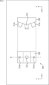
- FIG. 7 is a diagram illustrating a configuration example of a ranging module according to a third embodiment to which the technology according to the present disclosure is applied.
- the ranging module 500 shown in FIG. 7 includes a pair of light emitting devices 511a and 511b and an imaging device 512.
- the light emitting devices 511a and 511b are positioned and at an angle such that the combined irradiation range including the overlapping portion of the irradiation ranges of the respective irradiation lights includes the imaging range of the imaging device 512. Placed.
- the light emitting devices 511a and 511b are arranged so that the imaging device 512 is sandwiched therebetween, so that their respective light emitting directions are inclined with respect to the optical axis of the lens included in the imaging device 512. More specifically, the light emitting devices 511a and 511b are arranged so that their respective light emitting directions are symmetrical with respect to the optical axis direction (z-axis direction) of the lens.
- the light emitting devices 511a and 511b are arranged such that the center of each light emitting surface and the center of the lens of the imaging device 512 are aligned on the straight line VL (in the y-axis direction in the figure).
- the ranging module 500 includes a support structure 520 configured as a housing frame or a support substrate, which supports the light emitting devices 511a and 511b and the imaging device 512.
- a ranging module to which the technology of the present disclosure is applied can be installed in an area P1 near a rearview mirror inside a car, as shown in FIG. This makes it possible to understand the driving state of the driver and the seating status of fellow passengers by detecting the occupant's movements, line of sight, and estimating the skeletal structure based on the distance image acquired by the ranging module. Become.
- the distance measuring module to which the technology according to the present disclosure is applied may be installed in an area P2 near the door mirror on the driver's seat side, as shown in FIG. This makes it possible to at least understand the driving state of the driver based on the distance image acquired by the distance measurement module.
- a pair of (two) light emitting devices are provided for one imaging device.
- the combined irradiation range by the light-emitting devices is arranged at a position and angle such that it includes the imaging range of the imaging device, and three or more light-emitting devices may be provided for one imaging device.
- the present disclosure can take the following configuration.
- a plurality of light emitting devices that emit light to irradiate a distance measurement target; an imaging device that captures an image of reflected light from the irradiation light reflected by the distance measurement target;
- the plurality of light emitting devices are arranged at positions and angles such that a combined irradiation range including an overlapping portion of the irradiation ranges of the respective irradiation lights includes the imaging range of the imaging device.
- a casing having a front face facing the distance measurement object and to which the lens is exposed, and sloped faces on both sides of the front face that are inclined at the same angle in a direction opposite to the imaging direction of the imaging device. Equipped with a frame, The distance measuring module according to (7), wherein the pair of light emitting devices are each provided on the inclined surface.
- (11) comprising a support substrate on which the imaging device and a pair of the light emitting devices are mounted; The distance measuring module according to (10), wherein the pair of light emitting devices is mounted on the support substrate via a mount member having an inclined surface that is inclined at the same angle in a direction opposite to the imaging direction of the imaging device. . (12) The distance measuring module according to (11), wherein the pair of light emitting devices are mounted on the mount member such that the central axes of the respective light emitting directions do not intersect with each other. (13) The distance measuring module according to (11), wherein the pair of light emitting devices are mounted on the mount member so that the central axes of the respective light emitting directions intersect with each other.
- the light emitting device is configured with an LED (Light Emitting Diode) or an LD (Laser Diode).
- Ranging module 100 Ranging module, 111a, 111b Light emitting device, 112 Imaging device, 120 Support member, 200 ToF camera, 211a, 211b LD, 212 Camera, 220 Housing frame, 300 Measurement Distance module, 311a, 311b light emitting device, 312 imaging device , 320 Support board, 321 Mount member, 400 Ranging module, 411a, 411b Light emitting device, 412 Imaging device, 420 Support board, 421 Mount member
Landscapes
- Engineering & Computer Science (AREA)
- Physics & Mathematics (AREA)
- Radar, Positioning & Navigation (AREA)
- Remote Sensing (AREA)
- General Physics & Mathematics (AREA)
- Computer Networks & Wireless Communication (AREA)
- Electromagnetism (AREA)
- Measurement Of Optical Distance (AREA)
- Optical Radar Systems And Details Thereof (AREA)
- Studio Devices (AREA)
Abstract
Description
2.第1の実施形態(筐体フレームを支持構造として有する構成)
3.第2の実施形態(支持基板を支持構造として有する構成)
4.第3の実施形態(垂直方向に広角な測距を実現する構成)
5.適用例
図1は、従来の測距モジュールの構成例を示す図である。
図2は、本開示に係る技術を適用した第1の実施形態の測距モジュールの構成例を示す図である。
本実施形態の測距モジュールにおいては、一対の発光デバイスが、撮像デバイスを挟むように配置されるのではなく、撮像デバイスの一方に隣接して並ぶように配置されるものとする。
本実施形態の測距モジュールにおいては、上述した実施形態のように水平方向に広角な測距ではなく、垂直方向に広角な測距を実現する。
本開示に係る技術を適用した測距モジュールによれば、近距離でかつ広範囲な測距対象物の距離画像を取得することができる。
(1)
測距対象物に対する照射光を発光する複数の発光デバイスと、
前記照射光が前記測距対象物に反射した反射光を撮像する撮像デバイスと
を備え、
複数の前記発光デバイスは、それぞれの前記照射光の照射範囲の重複部分を含む合成照射範囲が、前記撮像デバイスの撮像範囲を含むような位置および角度で配置される
測距モジュール。
(2)
複数の前記発光デバイスは、それぞれの発光方向が、前記撮像デバイスが有するレンズの光軸に対して傾きを持つように配置される
(1)に記載の測距モジュール。
(3)
複数の前記発光デバイスは、それぞれ同じ発光タイミングで、それぞれ同じ発光強度の前記照射光を発光する
(2)に記載の測距モジュール。
(4)
一対の前記発光デバイスは、それぞれの発光方向が、前記レンズの光軸に対して線対称となるように配置される
(3)に記載の測距モジュール。
(5)
一対の前記発光デバイスは、それぞれの発光面の中心と、前記レンズの中心とが略同一直線上に並ぶように配置される
(4)に記載の測距モジュール。
(6)
一対の前記発光デバイスは、それぞれの前記照射範囲の一部が、前記レンズから遠くとも50cm以内の距離において重複するように配置される
(5)に記載の測距モジュール。
(7)
一対の前記発光デバイスは、前記撮像デバイスを挟むように配置される
(1)乃至(6)のいずれかに記載の測距モジュール。
(8)
前記測距対象物に正対した、前記レンズが露出する正対面と、前記正対面を挟んだ両側で前記撮像デバイスの撮像方向とは逆方向に互いに同角度だけ傾斜した傾斜面を有する筐体フレームを備え、
一対の前記発光デバイスは、それぞれ前記傾斜面上に設けられる
(7)に記載の測距モジュール。
(9)
前記筐体フレームは、前記撮像デバイスの撮像面と平行な載置面を有する
(8)に記載の測距モジュール。
(10)
一対の前記発光デバイスは、前記撮像デバイスの一方に隣接して並ぶように配置される
(1)乃至(6)のいずれかに記載の測距モジュール。
(11)
前記撮像デバイスと一対の前記発光デバイスが搭載される支持基板を備え、
一対の前記発光デバイスは、前記撮像デバイスの撮像方向とは逆方向に互いに同角度だけ傾斜した傾斜面を有するマウント部材を介して、前記支持基板に搭載される
(10)に記載の測距モジュール。
(12)
一対の前記発光デバイスは、それぞれの発光方向の中心軸が、互いに交差しないように、前記マウント部材に搭載される
(11)に記載の測距モジュール。
(13)
一対の前記発光デバイスは、それぞれの発光方向の中心軸が、互いに交差するように、前記マウント部材に搭載される
(11)に記載の測距モジュール。
(14)
前記撮像デバイスが有するレンズは、140°以上の画角を有する広角レンズである
(1)乃至(6)のいずれかに記載の測距モジュール。
(15)
前記発光デバイスは、LED(Light Emitting Diode)またはLD(Laser Diode)で構成される
(1)乃至(6)のいずれかに記載の測距モジュール。
Claims (15)
- 測距対象物に対する照射光を発光する複数の発光デバイスと、
前記照射光が前記測距対象物に反射した反射光を撮像する撮像デバイスと
を備え、
複数の前記発光デバイスは、それぞれの前記照射光の照射範囲の重複部分を含む合成照射範囲が、前記撮像デバイスの撮像範囲を含むような位置および角度で配置される
測距モジュール。 - 複数の前記発光デバイスは、それぞれの発光方向が、前記撮像デバイスが有するレンズの光軸に対して傾きを持つように配置される
請求項1に記載の測距モジュール。 - 複数の前記発光デバイスは、それぞれ同じ発光タイミングで、それぞれ同じ発光強度の前記照射光を発光する
請求項2に記載の測距モジュール。 - 一対の前記発光デバイスは、それぞれの発光方向が、前記レンズの光軸に対して線対称となるように配置される
請求項3に記載の測距モジュール。 - 一対の前記発光デバイスは、それぞれの発光面の中心と、前記レンズの中心とが略同一直線上に並ぶように配置される
請求項4に記載の測距モジュール。 - 一対の前記発光デバイスは、それぞれの前記照射範囲の一部が、前記レンズから遠くとも50cm以内の距離において重複するように配置される
請求項5に記載の測距モジュール。 - 一対の前記発光デバイスは、前記撮像デバイスを挟むように配置される
請求項6に記載の測距モジュール。 - 前記測距対象物に正対した、前記レンズが露出する正対面と、前記正対面を挟んだ両側で前記撮像デバイスの撮像方向とは逆方向に互いに同角度だけ傾斜した傾斜面を有する筐体フレームを備え、
一対の前記発光デバイスは、それぞれ前記傾斜面上に設けられる
請求項7に記載の測距モジュール。 - 前記筐体フレームは、前記撮像デバイスの撮像面と平行な載置面を有する
請求項8に記載の測距モジュール。 - 一対の前記発光デバイスは、前記撮像デバイスの一方に隣接して並ぶように配置される
請求項6に記載の測距モジュール。 - 前記撮像デバイスと一対の前記発光デバイスが搭載される支持基板を備え、
一対の前記発光デバイスは、前記撮像デバイスの撮像方向とは逆方向に互いに同角度だけ傾斜した傾斜面を有するマウント部材を介して、前記支持基板に搭載される
請求項10に記載の測距モジュール。 - 一対の前記発光デバイスは、それぞれの発光方向の中心軸が、互いに交差しないように、前記マウント部材に搭載される
請求項11に記載の測距モジュール。 - 一対の前記発光デバイスは、それぞれの発光方向の中心軸が、互いに交差するように、前記マウント部材に搭載される
請求項11に記載の測距モジュール。 - 前記撮像デバイスが有するレンズは、140°以上の画角を有する広角レンズである
請求項1に記載の測距モジュール。 - 前記発光デバイスは、LED(Light Emitting Diode)またはLD(Laser Diode)で構成される
請求項1に記載の測距モジュール。
Priority Applications (2)
| Application Number | Priority Date | Filing Date | Title |
|---|---|---|---|
| US18/848,511 US20250208261A1 (en) | 2022-03-28 | 2023-03-13 | Distance measuring module |
| CN202380025415.1A CN118871807A (zh) | 2022-03-28 | 2023-03-13 | 测距模块 |
Applications Claiming Priority (2)
| Application Number | Priority Date | Filing Date | Title |
|---|---|---|---|
| JP2022051130A JP2023144238A (ja) | 2022-03-28 | 2022-03-28 | 測距モジュール |
| JP2022-051130 | 2022-03-28 |
Publications (1)
| Publication Number | Publication Date |
|---|---|
| WO2023189458A1 true WO2023189458A1 (ja) | 2023-10-05 |
Family
ID=88200817
Family Applications (1)
| Application Number | Title | Priority Date | Filing Date |
|---|---|---|---|
| PCT/JP2023/009512 Ceased WO2023189458A1 (ja) | 2022-03-28 | 2023-03-13 | 測距モジュール |
Country Status (4)
| Country | Link |
|---|---|
| US (1) | US20250208261A1 (ja) |
| JP (1) | JP2023144238A (ja) |
| CN (1) | CN118871807A (ja) |
| WO (1) | WO2023189458A1 (ja) |
Cited By (1)
| Publication number | Priority date | Publication date | Assignee | Title |
|---|---|---|---|---|
| WO2026042412A1 (ja) * | 2024-08-23 | 2026-02-26 | ソニーセミコンダクタソリューションズ株式会社 | 測距モジュール、および、測距モジュールの調整方法 |
Citations (4)
| Publication number | Priority date | Publication date | Assignee | Title |
|---|---|---|---|---|
| WO2017213052A1 (ja) * | 2016-06-08 | 2017-12-14 | パナソニックIpマネジメント株式会社 | 測距システム及び測距方法 |
| CN111025329A (zh) * | 2019-12-12 | 2020-04-17 | 深圳奥比中光科技有限公司 | 一种基于飞行时间的深度相机及三维成像方法 |
| JP2021099278A (ja) * | 2019-12-23 | 2021-07-01 | 株式会社日立エルジーデータストレージ | 全方位測距装置 |
| CN113126060A (zh) * | 2020-01-16 | 2021-07-16 | 浙江舜宇智能光学技术有限公司 | Tof摄像模组及其驱动控制方法 |
-
2022
- 2022-03-28 JP JP2022051130A patent/JP2023144238A/ja active Pending
-
2023
- 2023-03-13 US US18/848,511 patent/US20250208261A1/en active Pending
- 2023-03-13 WO PCT/JP2023/009512 patent/WO2023189458A1/ja not_active Ceased
- 2023-03-13 CN CN202380025415.1A patent/CN118871807A/zh active Pending
Patent Citations (4)
| Publication number | Priority date | Publication date | Assignee | Title |
|---|---|---|---|---|
| WO2017213052A1 (ja) * | 2016-06-08 | 2017-12-14 | パナソニックIpマネジメント株式会社 | 測距システム及び測距方法 |
| CN111025329A (zh) * | 2019-12-12 | 2020-04-17 | 深圳奥比中光科技有限公司 | 一种基于飞行时间的深度相机及三维成像方法 |
| JP2021099278A (ja) * | 2019-12-23 | 2021-07-01 | 株式会社日立エルジーデータストレージ | 全方位測距装置 |
| CN113126060A (zh) * | 2020-01-16 | 2021-07-16 | 浙江舜宇智能光学技术有限公司 | Tof摄像模组及其驱动控制方法 |
Cited By (1)
| Publication number | Priority date | Publication date | Assignee | Title |
|---|---|---|---|---|
| WO2026042412A1 (ja) * | 2024-08-23 | 2026-02-26 | ソニーセミコンダクタソリューションズ株式会社 | 測距モジュール、および、測距モジュールの調整方法 |
Also Published As
| Publication number | Publication date |
|---|---|
| US20250208261A1 (en) | 2025-06-26 |
| JP2023144238A (ja) | 2023-10-11 |
| CN118871807A (zh) | 2024-10-29 |
Similar Documents
| Publication | Publication Date | Title |
|---|---|---|
| KR102464874B1 (ko) | 눈 추적을 구비한 후방 비전 시스템 | |
| US11393183B2 (en) | Integrated electronic module for 3D sensing applications, and 3D scanning device including the integrated electronic module | |
| US10711968B2 (en) | Vehicle lighting apparatus | |
| CN113030994A (zh) | 全方位测距装置 | |
| JP2001233139A (ja) | 車載用プレビューセンサの取り付け構造およびその位置ずれ調整装置 | |
| JPWO2019065218A1 (ja) | センサシステム | |
| EP3462237B1 (en) | Camera module | |
| WO2023189458A1 (ja) | 測距モジュール | |
| JP2016085187A (ja) | レーザレーダ装置 | |
| JP2022128450A (ja) | 距離測定装置、レーザレーダ及び移動ロボット | |
| JP2019197008A (ja) | 撮像装置 | |
| WO2024004297A1 (ja) | ヘッドアップディスプレイ装置 | |
| US20210373171A1 (en) | Lidar system | |
| JP2022153202A (ja) | インキャビンモニタリングシステム | |
| JP2020071487A (ja) | カメラ装置、運転支援システムおよび車両 | |
| JP7532926B2 (ja) | 撮像ユニットおよび車両制御ユニット | |
| JP2021109451A (ja) | インナーミラー内蔵撮像装置 | |
| WO2025009160A1 (ja) | 乗員モニタリングカメラ | |
| JP6774854B2 (ja) | 表示装置、及び、内装部材ユニット | |
| US20250071398A1 (en) | Means of Locomotion and Arrangement for Recording an Infrared Image | |
| CN120569648A (zh) | 集成式传感器及可移动平台 | |
| KR102525794B1 (ko) | 차량용 승객 감지 시스템 | |
| US12140287B1 (en) | Lamp assembly incorporating depth detection | |
| JP2023004762A (ja) | 車両用撮像装置 | |
| JP7805477B2 (ja) | 乗員撮像装置、及び、乗員撮像装置の製造方法 |
Legal Events
| Date | Code | Title | Description |
|---|---|---|---|
| 121 | Ep: the epo has been informed by wipo that ep was designated in this application |
Ref document number: 23779480 Country of ref document: EP Kind code of ref document: A1 |
|
| WWE | Wipo information: entry into national phase |
Ref document number: 202380025415.1 Country of ref document: CN |
|
| WWE | Wipo information: entry into national phase |
Ref document number: 18848511 Country of ref document: US |
|
| NENP | Non-entry into the national phase |
Ref country code: DE |
|
| 122 | Ep: pct application non-entry in european phase |
Ref document number: 23779480 Country of ref document: EP Kind code of ref document: A1 |
|
| WWP | Wipo information: published in national office |
Ref document number: 18848511 Country of ref document: US |