WO2023189368A1 - 蓄電池の劣化推定装置、及び蓄電池の劣化推定方法 - Google Patents
蓄電池の劣化推定装置、及び蓄電池の劣化推定方法 Download PDFInfo
- Publication number
- WO2023189368A1 WO2023189368A1 PCT/JP2023/009114 JP2023009114W WO2023189368A1 WO 2023189368 A1 WO2023189368 A1 WO 2023189368A1 JP 2023009114 W JP2023009114 W JP 2023009114W WO 2023189368 A1 WO2023189368 A1 WO 2023189368A1
- Authority
- WO
- WIPO (PCT)
- Prior art keywords
- storage battery
- smoothed
- voltage
- deterioration state
- deterioration
- Prior art date
- Legal status (The legal status is an assumption and is not a legal conclusion. Google has not performed a legal analysis and makes no representation as to the accuracy of the status listed.)
- Ceased
Links
Images







Classifications
-
- G—PHYSICS
- G01—MEASURING; TESTING
- G01R—MEASURING ELECTRIC VARIABLES; MEASURING MAGNETIC VARIABLES
- G01R31/00—Arrangements for testing electric properties; Arrangements for locating electric faults; Arrangements for electrical testing characterised by what is being tested not provided for elsewhere
- G01R31/36—Arrangements for testing, measuring or monitoring the electrical condition of accumulators or electric batteries, e.g. capacity or state of charge [SoC]
- G01R31/367—Software therefor, e.g. for battery testing using modelling or look-up tables
-
- G—PHYSICS
- G01—MEASURING; TESTING
- G01R—MEASURING ELECTRIC VARIABLES; MEASURING MAGNETIC VARIABLES
- G01R31/00—Arrangements for testing electric properties; Arrangements for locating electric faults; Arrangements for electrical testing characterised by what is being tested not provided for elsewhere
- G01R31/36—Arrangements for testing, measuring or monitoring the electrical condition of accumulators or electric batteries, e.g. capacity or state of charge [SoC]
-
- G—PHYSICS
- G01—MEASURING; TESTING
- G01R—MEASURING ELECTRIC VARIABLES; MEASURING MAGNETIC VARIABLES
- G01R31/00—Arrangements for testing electric properties; Arrangements for locating electric faults; Arrangements for electrical testing characterised by what is being tested not provided for elsewhere
- G01R31/36—Arrangements for testing, measuring or monitoring the electrical condition of accumulators or electric batteries, e.g. capacity or state of charge [SoC]
- G01R31/3644—Constructional arrangements
- G01R31/3648—Constructional arrangements comprising digital calculation means, e.g. for performing an algorithm
-
- G—PHYSICS
- G01—MEASURING; TESTING
- G01R—MEASURING ELECTRIC VARIABLES; MEASURING MAGNETIC VARIABLES
- G01R31/00—Arrangements for testing electric properties; Arrangements for locating electric faults; Arrangements for electrical testing characterised by what is being tested not provided for elsewhere
- G01R31/36—Arrangements for testing, measuring or monitoring the electrical condition of accumulators or electric batteries, e.g. capacity or state of charge [SoC]
- G01R31/385—Arrangements for measuring battery or accumulator variables
-
- G—PHYSICS
- G01—MEASURING; TESTING
- G01R—MEASURING ELECTRIC VARIABLES; MEASURING MAGNETIC VARIABLES
- G01R31/00—Arrangements for testing electric properties; Arrangements for locating electric faults; Arrangements for electrical testing characterised by what is being tested not provided for elsewhere
- G01R31/36—Arrangements for testing, measuring or monitoring the electrical condition of accumulators or electric batteries, e.g. capacity or state of charge [SoC]
- G01R31/385—Arrangements for measuring battery or accumulator variables
- G01R31/387—Determining ampere-hour charge capacity or SoC
-
- G—PHYSICS
- G01—MEASURING; TESTING
- G01R—MEASURING ELECTRIC VARIABLES; MEASURING MAGNETIC VARIABLES
- G01R31/00—Arrangements for testing electric properties; Arrangements for locating electric faults; Arrangements for electrical testing characterised by what is being tested not provided for elsewhere
- G01R31/36—Arrangements for testing, measuring or monitoring the electrical condition of accumulators or electric batteries, e.g. capacity or state of charge [SoC]
- G01R31/385—Arrangements for measuring battery or accumulator variables
- G01R31/387—Determining ampere-hour charge capacity or SoC
- G01R31/388—Determining ampere-hour charge capacity or SoC involving voltage measurements
-
- G—PHYSICS
- G01—MEASURING; TESTING
- G01R—MEASURING ELECTRIC VARIABLES; MEASURING MAGNETIC VARIABLES
- G01R31/00—Arrangements for testing electric properties; Arrangements for locating electric faults; Arrangements for electrical testing characterised by what is being tested not provided for elsewhere
- G01R31/36—Arrangements for testing, measuring or monitoring the electrical condition of accumulators or electric batteries, e.g. capacity or state of charge [SoC]
- G01R31/392—Determining battery ageing or deterioration, e.g. state of health
-
- H—ELECTRICITY
- H01—ELECTRIC ELEMENTS
- H01M—PROCESSES OR MEANS, e.g. BATTERIES, FOR THE DIRECT CONVERSION OF CHEMICAL ENERGY INTO ELECTRICAL ENERGY
- H01M10/00—Secondary cells; Manufacture thereof
- H01M10/42—Methods or arrangements for servicing or maintenance of secondary cells or secondary half-cells
-
- H—ELECTRICITY
- H01—ELECTRIC ELEMENTS
- H01M—PROCESSES OR MEANS, e.g. BATTERIES, FOR THE DIRECT CONVERSION OF CHEMICAL ENERGY INTO ELECTRICAL ENERGY
- H01M10/00—Secondary cells; Manufacture thereof
- H01M10/42—Methods or arrangements for servicing or maintenance of secondary cells or secondary half-cells
- H01M10/48—Accumulators combined with arrangements for measuring, testing or indicating the condition of cells, e.g. the level or density of the electrolyte
-
- H—ELECTRICITY
- H02—GENERATION; CONVERSION OR DISTRIBUTION OF ELECTRIC POWER
- H02J—ELECTRIC POWER NETWORKS; CIRCUIT ARRANGEMENTS OR SYSTEMS FOR SUPPLYING OR DISTRIBUTING ELECTRIC POWER; SYSTEMS FOR STORING ELECTRIC ENERGY
- H02J7/00—Circuit arrangements for charging or discharging batteries or for supplying loads from batteries
-
- Y—GENERAL TAGGING OF NEW TECHNOLOGICAL DEVELOPMENTS; GENERAL TAGGING OF CROSS-SECTIONAL TECHNOLOGIES SPANNING OVER SEVERAL SECTIONS OF THE IPC; TECHNICAL SUBJECTS COVERED BY FORMER USPC CROSS-REFERENCE ART COLLECTIONS [XRACs] AND DIGESTS
- Y02—TECHNOLOGIES OR APPLICATIONS FOR MITIGATION OR ADAPTATION AGAINST CLIMATE CHANGE
- Y02E—REDUCTION OF GREENHOUSE GAS [GHG] EMISSIONS, RELATED TO ENERGY GENERATION, TRANSMISSION OR DISTRIBUTION
- Y02E60/00—Enabling technologies; Technologies with a potential or indirect contribution to GHG emissions mitigation
- Y02E60/10—Energy storage using batteries
Definitions
- the present disclosure relates to a storage battery deterioration estimation device and a storage battery deterioration estimation method.
- a capacity maintenance rate (SOH: State of Health) is used as one of the indicators representing the deterioration state of a storage battery.
- SOH State of Health
- a storage battery has a characteristic that deterioration progresses with continued use, and the full charge capacity after deterioration becomes smaller than the initial full charge capacity.
- the capacity retention rate (SOH) is defined as the ratio of the full charge capacity after deterioration to the initial full charge capacity, and the smaller the value of the capacity retention rate (SOH), the more the deterioration of the storage battery progresses.
- SOH capacity maintenance rate
- SOH capacity maintenance rate
- Another method for calculating the capacity maintenance rate (SOH) of a storage battery is one that applies artificial intelligence (AI) technology, which inputs various states of the storage battery and calculates the capacity maintenance rate (SOH) of the storage battery.
- Machine learning methods have been developed in recent years that calculate using an estimated model learned by machine learning as an output.
- Patent Document 1 and Patent Document 2 disclose storage battery deterioration estimation devices using a machine learning method.
- the method of calculating the capacity retention rate (SOH) of a storage battery using the coulomb counting method described above, the method of calculating the capacity retention rate (SOH) of a storage battery using the SOC-OCV curve method, and the methods disclosed in Patent Document 1 and Patent Document 2 are not disclosed.
- the method of calculating the capacity maintenance rate (SOH) of storage batteries using a machine learning method has the following problems.
- the characteristics of the SOC-OCV curve vary depending on the temperature and the state of deterioration of the storage battery, resulting in calculation errors due to this variation in characteristics. .
- the present disclosure has been made in view of the above problems, and provides a storage battery deterioration estimation device that can estimate the deterioration state even when the storage battery is in use and can estimate the deterioration state with higher accuracy. and a method for estimating the deterioration of a storage battery.
- the storage battery deterioration estimating device of the present disclosure includes a first calculation that calculates the amount of voltage change of the storage battery obtained from a first voltage value measured when the storage battery is charged and discharged, and a second voltage value that is further measured. a second calculation unit that calculates the amount of change in charge of the storage battery obtained from the first current value measured when the storage battery is charged and discharged and the second current value that is further measured; and the amount of voltage change. , a measurement data storage unit that stores a plurality of measurement data including charge change amount, one or more voltage change amount, and one or more charge change amount as input, and machine learning that outputs the deterioration state of the storage battery.
- the estimated model storage unit stores the estimated model learned by the estimation model storage unit, and the estimated model stored in the estimated model storage unit is used to calculate one or more voltage changes and one or more charge changes stored in the measured data storage unit. and an estimator that receives the quantity as input and estimates the deterioration state of the storage battery.
- the storage battery deterioration estimation device of the present disclosure also provides a storage battery deterioration estimation device that calculates a voltage change amount of the storage battery obtained from a first voltage value measured when the storage battery is charged and discharged and a second voltage value that is further measured.
- a second calculation section that calculates the amount of charge change of the storage battery obtained from the first current value measured when the storage battery is charged and discharged and the further measured second current value, and a voltage change a measurement data storage unit that stores a plurality of measurement data including a voltage and a charge change amount; one or more voltage change amounts and one or more charge change amounts are input, and a deterioration state of the storage battery is outputted;
- an estimated model storage unit that stores an estimated model learned by machine learning and the estimated model stored in the estimated model storage unit, one or more voltage changes stored in the measured data storage unit and one or more an estimator that takes the charge change amount as input and estimates the deterioration state of the storage battery; and an estimator that takes the deterioration state of the storage battery output from the estimation part as input, smoothes the deterioration state of the storage battery using a low-pass filter, and outputs the result.
- a low-pass filter section that calculates the amount of charge change of the storage battery obtained from the first current value measured when the storage battery
- the storage battery deterioration estimation device of the present disclosure has a first low-pass filter section that receives as input a voltage measured when the storage battery is charged and discharged, smooths it using a low-pass filter, and outputs a smoothed voltage.
- a first calculation unit that calculates a smoothed voltage change amount of the storage battery obtained from the first smoothed voltage value outputted from the first low-pass filter unit and the second smoothed voltage value further outputted;
- a second low-pass filter section receives the current measured during charging and discharging, smooths it using a low-pass filter, and outputs a smoothed current;
- a second calculation unit that calculates a smoothed charge change amount of the storage battery obtained from the first smoothed current value and the further output second smoothed current value; and a plurality of measurements including a smoothed voltage change amount and a smoothed charge change amount.
- a measurement data storage unit that stores data, and an estimation model learned by machine learning that takes as input one or more smoothed voltage changes and one or more smoothed charge changes and outputs the deterioration state of the storage battery.
- An estimated model storage unit that stores the estimated model and the estimated model stored in the estimated model storage unit, inputs one or more smoothed voltage changes and one or more smoothed charge changes stored in the measured data storage unit,
- An estimation unit that estimates a deterioration state of the storage battery.
- the storage battery deterioration estimation device of the present disclosure has a first low-pass filter section that receives as input a voltage measured when the storage battery is charged and discharged, smooths it using a low-pass filter, and outputs a smoothed voltage.
- a first calculation unit that calculates a smoothed voltage change amount of the storage battery obtained from the first smoothed voltage value outputted from the first low-pass filter unit and the second smoothed voltage value further outputted;
- a second low-pass filter section receives the current measured during charging and discharging, smooths it using a low-pass filter, and outputs a smoothed current;
- a second calculation unit that calculates a smoothed charge change amount of the storage battery obtained from the first smoothed current value and the further output second smoothed current value; and a plurality of measurements including a smoothed voltage change amount and a smoothed charge change amount.
- a measurement data storage unit that stores data, and an estimation model learned by machine learning that takes as input one or more smoothed voltage changes and one or more of the charge changes and outputs the deterioration state of the storage battery.
- using an estimated model storage unit that stores the estimated model and the estimated model stored in the estimated model storage unit, inputs one or more smoothed voltage changes and one or more smoothed charge changes stored in the measured data storage unit, an estimating unit that estimates a deterioration state of the storage battery; and a third low-pass filter unit that receives the deterioration state of the storage battery outputted from the estimation unit, smoothes the deterioration state of the storage battery using a low-pass filter, and outputs the result. , is provided.
- the deterioration state of the storage battery in the storage battery deterioration estimating device of the present disclosure is preferably the capacity retention rate of the storage battery or the full charge capacity value of the storage battery.
- the device may further include a receiving communication unit that receives a new estimated model from the outside, and an updating unit that updates the estimated model stored in the estimated model storage unit to the new estimated model received from the receiving communication unit. preferable.
- an estimated data storage section that stores the deterioration state of the storage battery estimated by the estimation section, a plurality of measurement data stored in the measurement data storage section, and the deterioration state of the storage battery stored in the estimated data storage section. It is preferable to further include a transmission communication unit that transmits data.
- the storage battery deterioration estimation method of the present disclosure includes a calculation that calculates the amount of voltage change of the storage battery obtained from the first voltage value measured when the storage battery is charged and discharged, and the second voltage value that is further measured. a calculation step of calculating an amount of change in charge of the storage battery obtained from a first current value measured when the storage battery is charged and discharged and a second current value further measured; and one or more amount of voltage change.
- an estimation model learned by machine learning which takes as inputs , and 1 or more charge changes, and outputs the deterioration state of the storage battery, calculates 1 or more voltage changes and 1 or more charge changes. and an estimating step of estimating the deterioration state of the storage battery.
- the storage battery deterioration estimation method of the present disclosure includes a calculation that calculates the amount of voltage change of the storage battery obtained from the first voltage value measured when the storage battery is charged and discharged, and the second voltage value that is further measured. a calculation step of calculating an amount of change in charge of the storage battery obtained from a first current value measured when the storage battery is charged and discharged and a second current value further measured; and one or more amount of voltage change.
- an estimation model learned by machine learning which takes as inputs , and 1 or more charge changes, and outputs the deterioration state of the storage battery, calculates 1 or more voltage changes and 1 or more charge changes.
- the method includes an estimating step of taking the deterioration state of the storage battery as an input and estimating the deterioration state of the storage battery, and a calculation step of taking the deterioration state of the storage battery as an input and calculating the deterioration state of the storage battery smoothed using a low-pass filter.
- the storage battery deterioration estimation method of the present disclosure inputs the voltage measured when the storage battery is charged and discharged, and obtains a first smoothed voltage value obtained by smoothing it using a low-pass filter, and a first smoothed voltage value obtained by smoothing it using a low-pass filter.
- the method includes an estimating step of estimating the deterioration state of the storage battery using an estimation model learned by machine learning and inputting one or more smoothed voltage changes and one or more smoothed charge changes.
- the storage battery deterioration estimation method of the present disclosure inputs the voltage measured when the storage battery is charged and discharged, and obtains a first smoothed voltage value obtained by smoothing it using a low-pass filter, and a first smoothed voltage value obtained by smoothing it using a low-pass filter.
- a calculation step of calculating a second smoothed voltage value a calculation step of calculating a smoothed voltage change amount of the storage battery obtained from the first smoothed voltage value and the second smoothed voltage value;
- the deterioration state of the storage battery in the storage battery deterioration estimation method of the present disclosure is the capacity retention rate of the storage battery or the full charge capacity value of the storage battery.
- the storage battery deterioration estimation device and deterioration estimation method of the present disclosure it is possible to estimate the deterioration state even when the storage battery is in use, and it is possible to estimate the deterioration state with higher accuracy.
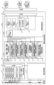
- FIG. 1 is a diagram showing the overall configuration of a storage battery deterioration estimation device according to a first embodiment of the present disclosure.
- FIG. 2 is a diagram illustrating the capacity maintenance rate (SOH) of a storage battery.
- FIG. 3 is a diagram illustrating the voltage measured when charging and discharging the storage battery according to the embodiment of the present disclosure, and calculation of the amount of voltage change.
- FIG. 4 is a diagram illustrating current measured when charging and discharging a storage battery according to an embodiment of the present disclosure, and calculation of a charge change amount.
- FIG. 5 is a diagram illustrating a configuration of a deterioration state estimation unit according to an embodiment of the present disclosure.
- FIG. 1 is a diagram showing the overall configuration of a storage battery deterioration estimation device according to a first embodiment of the present disclosure.
- FIG. 2 is a diagram illustrating the capacity maintenance rate (SOH) of a storage battery.
- FIG. 3 is a diagram illustrating the voltage measured when charging and discharging the
- FIG. 6 is a diagram illustrating another configuration of the deterioration state estimation unit according to the embodiment of the present disclosure.
- FIG. 7 is a flowchart illustrating a storage battery deterioration estimation method according to the first embodiment of the present disclosure.
- FIG. 8 is a diagram showing the deterioration estimation results of the storage battery according to the first embodiment of the present disclosure.
- FIG. 9 is a diagram showing the overall configuration of a storage battery deterioration estimation device according to a second embodiment of the present disclosure.
- FIG. 10 is a flowchart illustrating a storage battery deterioration estimation method according to the second embodiment of the present disclosure.
- FIG. 11 is a diagram illustrating deterioration estimation results of a storage battery according to the second embodiment of the present disclosure.
- FIG. 12 is a diagram showing the overall configuration of a storage battery deterioration estimation device according to a third embodiment of the present disclosure.
- FIG. 13 is a diagram showing the voltage measured when the storage battery according to the third embodiment of the present disclosure is charged and discharged, and the smoothed voltage smoothed using a low-pass filter.
- FIG. 14 is a flowchart showing a storage battery deterioration estimation method according to the third embodiment of the present disclosure.
- FIG. 15 is a diagram showing the overall configuration of a storage battery deterioration estimation device according to a fourth embodiment of the present disclosure.
- FIG. 16 is a flowchart illustrating a storage battery deterioration estimation method according to the fourth embodiment of the present disclosure.
- the storage battery deterioration estimating device and the storage battery deterioration estimation method of the present disclosure take as input the amount of voltage change and the amount of charge change obtained from the voltage value and current value that can be measured while the storage battery is in use, Using an estimation model trained by machine learning that outputs the deterioration state of the storage battery, it is possible to directly calculate the deterioration state of the storage battery from the amount of voltage change and the amount of charge change, which was not necessary with conventional technology. , there is no need to calculate the charging capacity required to bring the storage battery from a completely discharged state to a fully charged state, or to measure the OCV voltage after bringing the storage battery to a fully charged state.
- the deterioration state of the storage battery calculated using the estimation model is input, and the deterioration state of the storage battery calculated using the estimation model is smoothed and output using a low-pass filter. Even if there is a large error in the deterioration state of the storage battery from the actual deterioration state at a certain time, the output data will be smoothed to follow the previously output data by filter processing. Therefore, it is possible to estimate the deterioration state with less error.
- the voltage and current measured when charging and discharging the storage battery are input, and a low-pass filter is used to smooth the voltage and current of the storage battery to output a smoothed voltage and a smoothed current.
- the discrete voltage and current fluctuations are smoothed by following the previously measured voltage and current using a low-pass filter, making it possible to estimate the state of battery deterioration. Since the amount of voltage change and amount of charge change that are input to the estimation model are continuous data, it is possible to eliminate the effects of noise etc. from the amount of voltage change and amount of charge change, making it possible to create a storage battery with fewer errors. It becomes possible to estimate the deterioration state of
- the system also includes a reception communication section that receives an estimation model for estimating the deterioration state of the storage battery from the outside, and an update section that updates the estimation model stored in the deterioration estimation device to a new estimation model received from the reception communication section.
- a measured data storage unit stores a plurality of measurement data measured and calculated by the deterioration estimation device
- an estimated data storage unit stores the deterioration state of the storage battery estimated by the deterioration estimation device
- a measured data storage unit stores Even after the deterioration estimating device is installed in a product, the configuration includes a transmitting communication unit that transmits a plurality of measured data and the deterioration state of the storage battery stored in the estimated data storage unit to the outside. Since it is possible to collect measurement data of the storage battery when the deterioration estimating device is used and estimated data of the deterioration state of the storage battery, it is possible to add learning data for various usage states of the storage battery. This makes it possible to generate and update a new estimation model with higher accuracy, so it becomes possible to estimate the deterioration state with higher accuracy.
- each figure is a schematic diagram and is not necessarily strictly illustrated. Therefore, for example, the scales and the like in each figure do not necessarily match. Further, in each figure, substantially the same configurations are denoted by the same reference numerals, and overlapping explanations will be omitted or simplified.
- FIG. 1 is a diagram showing the overall configuration of a storage battery deterioration estimation device according to a first embodiment of the present disclosure.
- the storage battery 1 has a configuration in which a plurality of battery modules are connected in series and in parallel.
- the storage battery management device 10 is a device that is connected to the storage battery 1 and measures the voltage, current, and temperature of the storage battery 1, and includes an ADC that converts analog signal values corresponding to the voltage, current, and temperature of the storage battery 1 into digital signal values. (Analog Digital Converter) unit 11, a calculation unit 12 that processes the digital signal value that is the output of the ADC unit and calculates the voltage value, current value, and temperature; and the voltage value and current calculated by the calculation unit 12. It has a communication I/F 13 that transmits values and temperatures to the outside.
- ADC Analog Digital Converter
- the storage battery state estimation device 100a includes a communication I/F 41 that receives the voltage value, current value, and temperature of the storage battery 1 from the storage battery management device 10, and processes the data received from the communication I/F 41 to obtain various measured values of the storage battery 1.
- a storage battery measurement section 20a that calculates the storage battery measurement section 20a, a storage battery condition estimation section 30a that receives various measured values calculated by the storage battery measurement section 20a and estimates the deterioration state of the storage battery 1, and a storage battery 1 calculated by the storage battery condition estimation section 30a.
- an estimation model for estimating the deterioration state of the storage battery 1 and a communication I/F 42 that transmits and receives measured data and estimated data of the storage battery 1 to and from the outside.
- the storage battery state estimation device 100a is an example of a deterioration estimation device.
- the storage battery measurement unit 20a uses a measurement quantity acquisition unit 21 that acquires a voltage value, a current value, and a temperature from the communication I/F 41, and data stored in the measurement quantity acquisition unit 21, to obtain a starting voltage value that is a first voltage value.
- a voltage change amount calculation unit 22 that calculates a voltage change amount from a voltage value and an end voltage value that is a second voltage value, a starting current value that is a first current value, and an ending current value that is a second current value.
- a current change amount calculation unit 23 that calculates the amount of current change from , a charge amount calculation unit 24 that calculates the amount of charge of the storage battery 1 by integrating current values, and a charge amount calculation unit 24 that calculates the amount of charge of the storage battery 1 by integrating the current value.
- a charge change amount calculation unit 25 that calculates a charge change amount from a starting charge amount and an end charge amount of the storage battery 1, and a starting point necessary for calculating the above-mentioned voltage change amount, current change amount, and charge change amount. It has a measurement start/stop control section 26 that controls conditions and end conditions.
- the storage battery measurement unit 20a calculates various measurement parameters such as the amount of voltage change, the amount of current change, and the amount of charge change of the storage battery 1 using the voltage value and current value that are the measurement data of the storage battery 1. These measurement data are transmitted to a storage battery state estimation section 30a, which will be described later.
- the storage battery condition estimating unit 30a estimates the deterioration state of the storage battery 1 by inputting the measurement data storage unit 31 that stores the measurement data acquired and calculated by the storage battery measurement unit 20a, and the measurement data stored in the measurement data storage unit 31.
- a deterioration state calculation section 32a that constitutes the deterioration state calculation section 32a
- an estimated data storage section 33 that stores the deterioration state of the storage battery 1 estimated by the deterioration state calculation section 32a
- a deterioration state estimation section 32a that configures the deterioration state calculation section 32a.
- An estimated model storage unit 34 that stores an estimated model learned by machine learning used when estimating the deterioration state of the storage battery 1 in the unit 321; and an estimated model storage unit 34 that receives a new estimated model from the outside and stores it in the estimated model storage unit 34. and an estimated model updating unit 35 that updates the estimated model.
- the communication I/F 51 transmits and receives measurement data of the storage battery 1, estimation data, and an estimation model for estimating the deterioration state of the storage battery 1 via the communication I/F 42 of the storage battery state estimation device 100a.
- the deterioration state display unit 52 is a device that displays the deterioration state of the storage battery 1 estimated by the storage battery state estimation device 100a.
- the estimated model transmitter 53 is a device that transmits a new estimated model for estimating the deterioration state of the storage battery 1 to the storage battery state estimation device 100a.
- the measured data/estimated data receiving unit 54 is a device that receives data measured and estimated by the storage battery state estimation device 100a.
- the deterioration state estimating unit 321 of the storage battery state estimating unit 30a inputs the voltage change amount and the charge change amount of the storage battery 1, and It is characterized in that the capacity maintenance rate (SOH) of the storage battery 1 is estimated using an estimation model learned by machine learning, which outputs the capacity maintenance rate (SOH) which is the state.
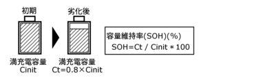
- FIG. 2 is a diagram illustrating the capacity maintenance rate (SOH) of the storage battery 1.
- FIG. 2 shows, as an example, a case where the full charge capacity Ct after deterioration is reduced to 80% of the initial full charge capacity Cinit.
- the capacity retention rate (SOH) (%) of the storage battery 1 is the ratio of the full charge capacity Ct after deterioration to the initial full charge capacity Cinit, and is expressed by the following equation 1.
- a deterioration estimating device for a storage battery 1 that can estimate a deterioration state even when the storage battery 1 is in use and can estimate the capacity maintenance rate (SOH) of the storage battery 1 with higher accuracy;
- SOH capacity maintenance rate
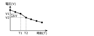
- FIG. 3 is a diagram illustrating the voltage measured when charging and discharging the storage battery 1 according to the embodiment of the present disclosure, and calculation of the amount of voltage change.
- the voltage change amount ⁇ V can be obtained by acquiring the voltage value V1 at time T1 and the voltage value V2 at the subsequent time T2, and calculating the difference V2 ⁇ V1 between the voltage value V1 and the voltage value V2. By repeating this operation, it is possible to obtain a plurality of voltage changes depending on the usage state of the storage battery 1.
- FIG. 4 is a diagram illustrating the calculation of the current measured when the storage battery 1 according to the embodiment of the present disclosure is charged and discharged, and the amount of change in charge.
- the charge change amount ⁇ Q can be obtained by acquiring the current value I1 at time T1 and the current value I2 at subsequent time T2, and integrating the current values as shown in the shaded area in FIG. By repeating this operation, it is possible to obtain a plurality of charge fluctuation amounts depending on the usage state of the storage battery 1.
- the voltage change amount ⁇ V and the charge change amount ⁇ Q of the storage battery 1 described above are calculated by the voltage change amount calculation section 22 and the charge change amount calculation section 25 of the storage battery measurement section 20a in the deterioration estimating device for the storage battery 1 shown in FIG. will do.
- the voltage change amount calculation section 22 is an example of a first calculation section
- the charge change amount calculation section 25 is an example of a second calculation section.
- SOH capacity maintenance rate
- FIG. 5 is a diagram showing the configuration of a deterioration state estimation unit according to an embodiment of the present disclosure.
- the deterioration state estimating unit 321 uses an estimation model learned by machine learning, which inputs one or more voltage changes and one or more charge changes and outputs the capacity maintenance rate (SOH) of the storage battery 1. Calculate the capacity maintenance rate (SOH) of the storage battery 1.
- the deterioration state estimation section 321 is composed of a neural network calculation section 3211, and the neural network calculation section 3211 is composed of a fully connected neural network (FCN).
- FIG. 6 is a diagram showing another configuration of the deterioration state estimation unit according to the embodiment of the present disclosure.
- the deterioration state estimating unit 321 in FIG. 5 described above is composed only of a neural network calculation unit 3211, and has a configuration in which one or more voltage changes and one or more charge changes are directly input to the neural network calculation unit 3211.
- the deterioration state estimation unit 321 in FIG. 6 differs in that a feature amount calculation unit 3212 is added before the neural network calculation unit 3211. That is, the deterioration state estimating unit 321 in FIG.
- the feature is that new feature quantities such as the average value of one or more charge change amounts, and change amount differences are calculated, and the output thereof is input to the neural network calculation unit 3211.
- the feature quantity calculation unit 3212 calculates the optimum feature quantities for machine learning, and uses these as input to estimate the capacity maintenance rate (SOH) of the storage battery 1 using machine learning.
- SOH capacity maintenance rate
- the estimation model using machine learning of the neural network calculation unit 3211 is a fully connected neural network (FCN) has been explained.
- a model for example, a recurrent neural network (RNN), a decision tree type machine learning estimation model, a multiple regression analysis type machine learning estimation model, etc. may be used.
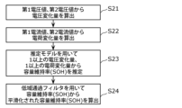
- FIG. 7 is a flowchart illustrating a storage battery deterioration estimation method according to the first embodiment of the present disclosure.
- the voltage change amount calculation unit 22 calculates the voltage change amount from the first voltage value and the second voltage value that are measured when the storage battery 1 is charged and discharged (S11).
- the charge change amount calculation unit 25 calculates the charge change amount from the first current value and the second current value that are measured when the storage battery is charged and discharged (S12).
- the deterioration state estimating unit 321 estimates the capacity maintenance rate (SOH) of the storage battery 1 from one or more voltage changes and one or more charge changes using the estimation model (S13).
- the second voltage value is a voltage value acquired after the first voltage value, and may be a voltage value acquired continuously after the first voltage value, or a voltage value acquired at a predetermined time interval. It may be.
- the second current value is a current value acquired after the first current value, and may be a current value acquired continuously after the first current value, or a current value acquired after a predetermined time interval. It may be a current value.
- the first voltage value and the first current value may be acquired at the same position and time, or may be acquired at different times, and similarly, the second voltage value and the second current value are acquired at the same position and time. or may be obtained at different times.
- the input data for estimating the capacity maintenance rate (SOH) of the storage battery 1 is the voltage (voltage change amount) and current (charge change amount) measured when the storage battery 1 is used. , and since measurement data of the storage battery 1 in the fully charged state is not required, it is possible to estimate the deterioration state even when the storage battery 1 is in use.
- the configuration calculates the capacity maintenance rate (SOH) of the storage battery 1 using an estimation model learned by machine learning, it is possible to prepare a large amount of learning data and learn the estimation model using machine learning. Since it is possible to estimate the deterioration state of the storage battery 1 under various usage conditions, it is possible to estimate the deterioration state of the storage battery 1 with higher accuracy.
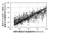
- FIG. 8 is a diagram showing the deterioration estimation results of the storage battery 1 according to the first embodiment of the present disclosure.
- the number of learning data is approximately 5000 data, which is very small compared to the learning data used when developing a model for estimating the deterioration state of the storage battery 1 installed in an actual product. This was done to simply verify the effects of the present disclosure.
- the horizontal axis is the actual capacity retention rate (SOH) of the storage battery 1
- the vertical axis is the capacity retention rate (SOH) of the storage battery 1 estimated using the estimation model learned by machine learning.
- the value on the horizontal axis and the value on the vertical axis plotted at the same location are estimates of the capacity maintenance rate (SOH) of storage battery 1 estimated using the estimation model learned by machine learning. The results show that the actual capacity maintenance rate (SOH) of the storage battery 1 is estimated correctly.
- the capacity maintenance rate (SOH) of the storage battery 1 estimated using the estimation model learned by machine learning is different from the actual capacity maintenance rate of the storage battery 1. It can be seen that the rate (SOH) can be estimated. However, the capacity maintenance rate (SOH) of storage battery 1 estimated using the estimation model learned by machine learning has a maximum error of about 8% with respect to the actual capacity maintenance rate (SOH) of storage battery 1. Some of them are estimated, and it is possible to reduce the error by optimizing the learning method of the estimation model or by increasing the training data and developing a more accurate estimation model. .
- the learning data is data that uses voltage (amount of voltage change) and current (amount of charge change) as input information, and uses the capacity retention rate (SOH) at that time as output information.
- the storage battery deterioration estimating device in the embodiment of the present disclosure receives from the outside a new estimation model for estimating the capacity maintenance rate (SOH) of the storage battery 1, and uses the estimation model stored in the storage battery 1 deterioration estimating device. It is possible to update.
- SOH capacity maintenance rate
- the estimated model update unit 35 of the storage battery state estimation unit 30a of the storage battery state estimation device 100a is transmitted to the estimated model update unit 35 of the storage battery state estimation unit 30a of the storage battery state estimation device 100a via the I/F 51 and the communication I/F 42. Thereafter, the estimated model update unit 35 can update the estimated model stored in the estimated model storage unit 34 to a new estimated model.
- the deterioration estimation device for the storage battery 1 in the embodiment of the present disclosure is capable of transmitting measurement data of the storage battery 1 and estimated data of the deterioration state of the storage battery 1 to the outside.
- FIG. 9 is a diagram showing the overall configuration of a storage battery deterioration estimation device according to a second embodiment of the present disclosure.
- components that are the same as those in FIG. 1, which is the deterioration estimating device for the storage battery 1 according to the first embodiment described above, are given the same names, codes, and numbers, and detailed explanations thereof are omitted. do.
- the deterioration estimating device for a storage battery 1 according to the second embodiment is different from the first embodiment in the configuration of a storage battery state estimation unit 30b of a storage battery state estimation device 100b in FIG.
- a deterioration state low-pass filter section 322 is newly installed on the output of the deterioration state estimation section 321, and the deterioration state low-pass filter section 322 outputs the deterioration state low-pass filter section 322.
- the degraded state low-pass filter section 322 is characterized by performing filter processing to smooth input data, which is time series data, and output the smoothed data as output data.
- n is an integer value
- the n-th output data y[n] of the deteriorated state low-pass filter section 322 is the previously output n-1th output data y[n-1]
- It is determined by the n-th input data x[n] and is expressed by the following equation 2.
- the degraded state low-pass filter unit 322 has the n-th output data y[n] track the previously output n-1-th output data y[n-1], and the n-th input data y[n].
- x[n] is also reflected output data, and functions as a filter processing unit that smoothes input data that is time series data and outputs it as output data.
- FIG. 10 is a flowchart illustrating a storage battery deterioration estimation method according to the second embodiment of the present disclosure.
- the voltage change amount calculation unit 22 calculates the voltage change amount from the first voltage value and the second voltage value that are measured when the storage battery 1 is charged and discharged (S21).
- the charge change amount calculation unit 25 calculates the charge change amount from the first current value and the second current value that are measured when the storage battery 1 is charged and discharged (S22).
- the deterioration state estimating unit 321 estimates the capacity maintenance rate (SOH) of the storage battery 1 from one or more voltage changes and one or more charge changes using the estimation model (S23).
- the deteriorated state low-pass filter unit 322 uses a low-pass filter to calculate the capacity retention rate (SOH) of the storage battery 1 smoothed from the capacity retention rate (SOH) of the storage battery 1 calculated in step S23. is calculated (S24).
- the deterioration state of the storage battery 1 calculated using the estimation model is input, and the deterioration state of the storage battery 1 is smoothed using a low-pass filter and output. Even if the deterioration state of the storage battery 1 calculated using the method has a large error with respect to the actual deterioration state of the storage battery 1 at a certain time, it will follow the previously output data by filter processing. Since the output data is smoothed and output, it is possible to estimate the deterioration state of the storage battery 1 with less error.
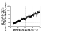
- FIG. 11 is a diagram illustrating deterioration estimation results of a storage battery according to the second embodiment of the present disclosure.
- the learning data used to train the estimation model and the input data used to estimate the capacity maintenance rate (SOH) of the storage battery 1 are the same as in the first embodiment described above. .
- the horizontal axis is the actual capacity maintenance rate (SOH) of the storage battery 1
- the vertical axis is the capacity maintenance rate (SOH) of the storage battery 1 estimated using the estimation model learned by machine learning.
- SOH capacity maintenance rate
- the values on the horizontal axis and the values on the vertical axis are plotted at the same location with respect to the capacity maintenance rate (SOH) of storage battery 1 estimated using the estimation model learned by machine learning. This shows that the capacity retention rate (SOH) of the storage battery 1 smoothed using filter processing correctly estimates the actual value of the capacity retention rate (SOH) of the storage battery 1.
- the capacity maintenance rate (SOH) of the storage battery 1 estimated using the estimation model learned by machine learning is It can be seen that the actual capacity maintenance rate (SOH) of the storage battery 1 can be estimated. Furthermore, compared to the estimation result of the first embodiment shown in FIG. 8, the estimation result of the second embodiment shown in FIG. It can be seen that this has been reduced. That is, the estimation results of the first embodiment shown in FIG. 8 have a maximum error of approximately 8% with respect to the actual capacity maintenance rate (SOH) of the storage battery 1, whereas the estimation results shown in FIG.
- the estimation result of the second embodiment is reduced to a maximum error of about 5% or less with respect to the actual capacity maintenance rate (SOH) of the storage battery 1.
- SOH actual capacity maintenance rate
- FIG. 12 is a diagram showing the overall configuration of a storage battery deterioration estimation device according to a third embodiment of the present disclosure.
- the components that are the same as those in FIG. 1, which is the deterioration estimating device for the storage battery 1 according to the first embodiment described above, are given the same names, codes, and numbers, and detailed explanations thereof are omitted. do.
- the deterioration estimating device for a storage battery 1 according to the third embodiment differs from the first embodiment in the configuration of a storage battery measurement unit 20b of a storage battery state estimation device 100c in FIG. 12. Specifically, the deterioration estimating device for a storage battery 1 according to the third embodiment provides a storage battery measurement unit 20b with a voltage low value that smoothes a voltage value inputted by a low-pass filter and outputs it as a smoothed voltage value. It is newly equipped with a band pass filter section 27 and a current low pass filter section 28 which smoothes the current value inputted by the low pass filter and outputs it as a smoothed current value.
- the filter processing of the voltage low-pass filter section 27 and the current low-pass filter section 28 is similar to the filter processing of the deteriorated state low-pass filter section 322 in the second embodiment described above, A detailed explanation will be omitted.
- the voltage value acquired by the measurement quantity acquisition unit 21 is input to the voltage low-pass filter unit 27, and is output as a smoothed voltage.
- the smoothed voltage output from the voltage low-pass filter section 27 is input to the voltage change amount calculation section 22, where the smoothed voltage change amount is calculated, and the smoothed voltage is stored in the measured data storage section of the storage battery state estimation section 30a. 31.
- the current value acquired by the measured quantity acquisition section 21 is input to the current low-pass filter section 28, and is output as a smoothed current.
- the smoothed current output from the current low-pass filter unit 28 is input to the current change amount calculation unit 23 and the charge amount calculation unit 24, and the output of the charge amount calculation unit 24 is input to the charge change amount calculation unit 25, and the smoothed current is smoothed.
- the amount of charge change is calculated.
- the smoothed charge change amount calculated by the charge change amount calculation section 25 is stored in the measured data storage section 31 of the storage battery state estimation section 30a.
- the estimation model for calculating the capacity maintenance rate (SOH) of the storage battery 1 stored in the estimation model storage unit 34 of the storage battery state estimation unit 30a receives the smoothed voltage value and the smoothed current value as input, and calculates the capacity maintenance rate (SOH) of the storage battery 1 by inputting the smoothed voltage value and the smoothed current value.
- An estimated model learned by machine learning, whose output is SOH), is stored.
- a deterioration estimating device for a storage battery 1 smoothes voltage and current values measured from the storage battery 1 using a voltage low-pass filter and a current low-pass filter.
- the smoothed voltage value and the smoothed current value are calculated, the smoothed voltage change amount and the smoothed charge change amount are calculated from the smoothed voltage value and the smoothed current value, and the smoothed voltage change amount and the smoothed charge change amount are input.
- the capacity maintenance rate (SOH) of the storage battery 1 is calculated using an estimation model learned by machine learning, which outputs the capacity maintenance rate (SOH) of the storage battery 1.
- FIG. 13 is a diagram illustrating the voltage measured when charging and discharging the storage battery according to the third embodiment of the present disclosure, and the smoothed voltage smoothed using a low-pass filter.
- the horizontal axis is time, and the vertical axis is voltage value. 27) is shown.
- the voltage measured from the storage battery 1 is affected by steep fluctuations in the charging/discharging current of the storage battery 1, measurement noise, etc., and the voltage fluctuations are not continuous but discrete for each measurement.
- the discrete voltage values measured from the storage battery 1 are smoothed to follow the previously measured voltage values, so that the deterioration state of the storage battery 1 is
- the amount of voltage change that is input to the estimation model that estimates is also a smoothed continuous value, making it possible to eliminate the effects of noise etc. from the voltage value of storage battery 1 and the amount of voltage fluctuation, resulting in fewer errors. It becomes possible to estimate the deterioration state of the storage battery 1.
- FIG. 13 relates to the voltage and smoothed voltage measured from the storage battery 1, the same applies to the current and smoothed current measured from the storage battery 1.
- FIG. 14 is a flowchart showing a storage battery deterioration estimation method according to the third embodiment of the present disclosure.
- the voltage low-pass filter section 27 uses a low-pass filter to calculate a first smoothed voltage value and a second smoothed voltage value for the voltage measured when the storage battery 1 is charged and discharged. (S31).
- the voltage change amount calculation unit 22 calculates the smoothed voltage change amount from the first smoothed voltage value and the second smoothed voltage value calculated in step S31 (S32).
- the current low-pass filter section 28 uses a low-pass filter to calculate a first smoothed current value and a second smoothed current value for the current measured when the storage battery 1 is charged and discharged. (S33).
- the charge change amount calculation unit 25 calculates the smoothed charge change amount from the first smoothed current value and the second smoothed current value calculated in step S33 (S34).
- the deterioration state estimating unit 321 estimates the capacity retention rate (SOH) of the storage battery 1 from one or more smoothed voltage changes and one or more smoothed charge changes using the estimation model (S35).
- the voltage and current measured when the storage battery 1 is charged and discharged are input, and the voltage and current of the storage battery 1 are smoothed using a low-pass filter to create a smoothed voltage and a smoothed current.
- the smoothed voltage change amount and smoothed charge change amount obtained from the smoothed voltage and smoothed current are input, and the deterioration state of the storage battery 1 is output.
- the configuration is such that the deterioration state of the storage battery 1 is calculated.
- the voltage and current measured from the storage battery 1 are affected by steep fluctuations in the charging/discharging current of the storage battery 1, measurement noise, etc., and are subject to discrete voltage and current fluctuations that are not continuous for each measurement. Even if this occurs, the discrete voltage and current fluctuations are smoothed by following the previously measured voltage and current using a low-pass filter, so the deterioration state of the storage battery 1 can be minimized.
- the amount of voltage change and the amount of charge change that are input to the estimation model to be estimated become continuous data. It becomes possible to eliminate the influence of noise and the like from the voltage change amount and charge change amount, which are continuous data, and it becomes possible to estimate the deterioration state of the storage battery 1 with less error.
- FIG. 15 is a diagram showing the overall configuration of a storage battery deterioration estimation device according to a fourth embodiment of the present disclosure.
- the constituent elements of any one of FIG. 1, FIG. 9, and FIG. Identical items are given the same names, codes, and numbers, and detailed explanations thereof will be omitted.
- the configuration of the storage battery measurement unit 20b of the storage battery condition estimation device 100d is the same as that of the third embodiment, and the configuration of the storage battery condition estimation unit 30b is the same as that of the second embodiment. It has the same configuration as the embodiment. That is, as explained in the second embodiment and the third embodiment, the deterioration estimating device for the storage battery 1 according to the fourth embodiment uses a low-pass Calculate the smoothed voltage and smoothed current using a filter, calculate the smoothed voltage change amount and the smoothed charge change amount from the smoothed voltage and smoothed current, and calculate the smoothed voltage change amount and the smoothed charge change amount.
- the capacity maintenance rate (SOH) of the storage battery 1 is calculated using an estimation model learned by machine learning, which takes the capacity maintenance rate (SOH) of the storage battery 1 as an input and the output is the capacity maintenance rate (SOH) of the storage battery 1.
- the method is characterized in that the capacity retention rate (SOH) of the storage battery 1 is calculated using a low-pass filter to smooth the capacity retention rate (SOH) of the storage battery 1.
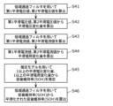
- FIG. 16 is a flowchart illustrating a storage battery deterioration estimation method according to the fourth embodiment of the present disclosure.
- the voltage low-pass filter section 27 uses a low-pass filter to calculate a first smoothed voltage value and a second smoothed voltage value for the voltage measured when the storage battery 1 is charged and discharged. (S41).
- the voltage change amount calculation unit 22 calculates the smoothed voltage change amount from the first smoothed voltage value and the second smoothed voltage value calculated in step S41 (S42).
- the current low-pass filter section 28 uses a low-pass filter to calculate a first smoothed current value and a second smoothed current value for the current measured when the storage battery 1 is charged and discharged. (S43).
- the charge change amount calculation unit 25 calculates a smoothed charge change amount from the first smoothed current value and the second smoothed current value calculated in step S43 (S44).
- the deterioration state estimating unit 321 estimates the capacity maintenance rate (SOH) of the storage battery 1 from one or more smoothed voltage changes and one or more smoothed charge changes using the estimation model (S45).
- the deteriorated state low-pass filter unit 322 uses a low-pass filter to calculate the capacity retention rate (SOH) of the storage battery 1 smoothed from the capacity retention rate (SOH) of the storage battery 1 calculated in step S45. is calculated (S46).
- the smoothed voltage is smoothed to follow the previously output voltage value and current value. It is learned by machine learning that calculates the value and smoothed current value, inputs the smoothed voltage change amount and smoothed charge change amount obtained from the smoothed voltage value and smoothed current value, and outputs the deterioration state of the storage battery 1.
- the deterioration state of the storage battery 1 is estimated using the estimated model. With this configuration, it is possible to eliminate the influence of noise and the like from the voltage change amount and the charge change amount, and it is possible to estimate the deterioration state of the storage battery 1 with less error.
- the deterioration state of the storage battery 1 is smoothed and output. Even in the unlikely event that the deterioration state of the storage battery 1 has a large error with respect to the actual deterioration state of the storage battery 1 at a certain time, the output data is adjusted to follow the previously output data by filter processing. Since it is smoothed and output, it becomes possible to estimate the deterioration state of the storage battery 1 with less error.
- the storage battery deterioration estimation device and the deterioration estimation method of the present disclosure calculate the voltage change amount and the charge change amount from the voltage and current measured when the storage battery is charged and discharged, and calculate the voltage change amount and the charge change amount.
- the configuration outputs the deterioration state of the storage battery using an estimation model learned by machine learning, which takes the amount of change in charge and the amount of change in charge as input, and outputs the deterioration state of the storage battery. It is possible to estimate the deterioration state even if there is a problem, and it is possible to estimate the deterioration state with higher accuracy.
- the structure by configuring the structure to output the deterioration state of the storage battery calculated by the estimation model as the deterioration state of the storage battery smoothed by filter processing, it is possible to estimate the deterioration state of the storage battery with less error. becomes. Furthermore, a smoothed voltage value and a smoothed current value are calculated by filter processing for the voltage and current measured from the storage battery, and the smoothed voltage change amount and smoothed charge are calculated from the smoothed voltage value and smoothed current value. By calculating the amount of change and estimating the deterioration state of the storage battery, it is possible to eliminate the effects of noise, etc. on the voltage and current measured from the storage battery, and it is possible to estimate the deterioration state of the storage battery with less error. It becomes possible to estimate.
- the estimation model for estimating the deterioration state of the storage battery stored in the storage battery deterioration estimating device is configured to be updated to a new estimation model, even after the storage battery deterioration estimating device is installed in the product, the accuracy will be higher. Since it becomes possible to update the estimation model to one that can estimate the deterioration state of the storage battery, it becomes possible to estimate the deterioration state of the storage battery with higher accuracy.
- the storage battery will not be used. It becomes possible to collect measurement data of the storage battery when the storage battery is damaged, and estimated data of the deterioration state of the storage battery. This makes it possible to learn and update a new estimation model with higher accuracy using learning data that includes various usage states of storage batteries, so it is possible to estimate the deterioration state of storage batteries with higher accuracy. becomes possible.
- the storage battery deterioration estimating device and deterioration estimation method of the present disclosure are not limited to the above-mentioned examples, and may be applied within the scope of the gist of the present disclosure.
- the present invention is also effective for embodiments in which various changes that can be thought of by those skilled in the art are made, and also for embodiments constructed by combining components of different embodiments.
- the specific configuration of the storage battery state estimation device in the storage battery deterioration estimation device of this embodiment is not limited to the configuration shown in this embodiment.
- the measured amount acquisition unit, the voltage change The structure is composed of a quantity calculation section, a current change amount calculation section, a charge amount calculation section, a charge change amount calculation section, a measurement start/stop control section, a voltage low-pass filter section, and a current low-pass filter section.
- the present invention is not limited to the above, and other configurations may be used as long as the amount of change in voltage and amount of change in charge of the storage battery, or the amount of smoothed voltage change and the amount of smoothed charge change can be calculated.
- an estimation model learned by machine learning using a fully connected neural network has been described, but it is not limited to the above.
- An estimation model capable of estimating the deterioration state of the storage battery may be employed, such as a machine learning estimation model or a multiple regression analysis type machine learning estimation model.
- each component may be configured with dedicated hardware, or may be realized by executing a software program suitable for each component.
- Each component may be realized by a program execution unit such as a CPU or a processor reading and executing a software program recorded on a recording medium such as a hard disk or a semiconductor memory.
- each of the components described in the above embodiments may be realized as software, or typically, as an LSI that is an integrated circuit. These may be individually integrated into one chip, or may be integrated into one chip including some or all of them. Although it is referred to as an LSI here, it may also be called an IC, VLSI, ULSI, or system LSI depending on the degree of integration. Further, the method of circuit integration is not limited to LSI, and may be implemented using a dedicated circuit or a general-purpose processor.
- one aspect of the present disclosure may be a computer program that causes a computer to execute each characteristic step included in the storage battery deterioration estimation method shown in any one of FIGS. 7, 10, 14, and 16. good.
- the program may be a program to be executed by a computer.
- one aspect of the present disclosure may be a computer-readable non-transitory recording medium in which such a program is recorded.
- such a program may be recorded on a recording medium and distributed or distributed. For example, by installing a distributed program on a device having another processor and having that processor execute the program, it is possible to cause that device to perform each of the above processes.
- the storage battery deterioration estimation device and deterioration estimation method according to the present disclosure can estimate the deterioration state even when the storage battery is in use, and can estimate the deterioration state with higher accuracy. Therefore, for example, electric bicycles, electric motorcycles, electric cars, electric airplanes, electric ships, electric agricultural machines, drones, automatic transportation equipment, industrial robots, power storage systems, etc., especially those that use storage batteries as a power source for long periods of time, are This is useful for equipment that operates and that would have a major impact on business execution or system operation if it were to run out of power or malfunction.
- Storage battery 10 Storage battery management device 11 ADC section 12 Arithmetic section 13 Communication I/F 20a, 20b Storage battery measurement section 21 Measured amount acquisition section 22 Voltage change amount calculation section 23 Current change amount calculation section 24 Charge amount calculation section 25 Charge change amount calculation section 26 Measurement start/stop control section 27 Voltage low-pass filter section 28 Current Low-pass filter sections 30a, 30b Storage battery state estimating section 31 Measured data storage section 32a, 32b Deterioration state calculation section 33 Estimated data storage section 34 Estimated model storage section 35 Estimated model update section 41, 42, 51 Communication I/F 52 Deterioration state display section 53 Estimated model transmission section 54 Measured data/estimated data reception section 100a, 100b, 100c, 100d Storage battery state estimation device 321 Deterioration state estimation section 322 Deterioration state low-pass filter section 3211 Neural network calculation section 3212 Feature amount calculation section
Landscapes
- Physics & Mathematics (AREA)
- General Physics & Mathematics (AREA)
- Engineering & Computer Science (AREA)
- Manufacturing & Machinery (AREA)
- Chemical & Material Sciences (AREA)
- Chemical Kinetics & Catalysis (AREA)
- Electrochemistry (AREA)
- General Chemical & Material Sciences (AREA)
- Power Engineering (AREA)
- Secondary Cells (AREA)
Abstract
劣化推定装置は、蓄電池(1)を充放電させたときに測定された第1電圧値と第2電圧値とから得られる蓄電池(1)の電圧変化量を算出する第1計算部(電圧変化量算出部(22))と、蓄電池(1)を充放電させたときに測定された第1電流値と第2電流値とから得られる蓄電池(1)の電荷変化量を算出する第2計算部(電荷変化量算出部(25))と、電圧変化量と電荷変化量とを含む複数の測定データを格納する測定データ記憶部(31)と、1以上の電圧変化量と1以上の電荷変化量とを入力とし、蓄電池(1)の劣化状態を出力する推定モデルを格納する推定モデル記憶部(34)と、推定モデルを用いて、1以上の電圧変化量と1以上の電荷変化量とを入力とし、蓄電池(1)の劣化状態を推定する推定部(劣化状態推定部(321))とを備える。
Description
本開示は、蓄電池の劣化推定装置、及び蓄電池の劣化推定方法に関する。
近年、蓄電池などのバッテリー電源で動作する機器が幅広い分野で利用されている。これらの機器を安全に利用するためには、蓄電池の電欠状態や故障に至る事態を防ぐ必要があり、蓄電池の劣化状態を正確に把握する必要がある。
蓄電池の劣化状態を表す指標の1つとして容量維持率(SOH:State Of Health)が用いられる。蓄電池は使用を継続することで劣化が進行し、劣化後の満充電容量は初期の満充電容量より小さな値となる特性を有する。容量維持率(SOH)は、劣化後の満充電容量と初期の満充電容量との比で定義され、容量維持率(SOH)の値が小さくなるほど蓄電池の劣化が進行していることを示す。
蓄電池の容量維持率(SOH)を算出する方法として、完全に放電された蓄電池に対して、満充電が完了するまでの充電電流を積算して満充電容量を算出し、初期の満充電容量で除することで算出するクーロンカウント方式がある。
また、蓄電池の容量維持率(SOH)を算出する別の方法として、満充電時のOCV(Open Circuit Voltage)電圧を測定し、SOC(State Of Charge)-OCV曲線から満充電容量を算出し、初期の満充電容量で除することで算出するSOC-OCV曲線方式がある。
また、蓄電池の容量維持率(SOH)を算出する別の方法として、人工知能(AI:Artificial Intelligence)技術を応用したものであり、蓄電池の各種状態を入力、蓄電池の容量維持率(SOH)を出力とする、機械学習により学習された推定モデルを用いて算出する機械学習方式が近年開発されている。特許文献1、及び特許文献2には、機械学習方式による蓄電池の劣化推定装置が開示されている。
しかしながら、前述したクーロンカウント方式による蓄電池の容量維持率(SOH)の算出方法、SOC-OCV曲線方式による蓄電池の容量維持率(SOH)の算出方法、並びに特許文献1、及び特許文献2に開示されている機械学習方式による蓄電池の容量維持率(SOH)の算出方法では以下に示す課題があった。
クーロンカウント方式による蓄電池の容量維持率(SOH)の算出方法では、蓄電池を完全に放電された状態から満充電にするという作業が必要であり、このような作業を蓄電池が搭載された機器で実施するのは利便性が悪く、さらに蓄電池が搭載された機器が常時動作するような場合では、本方式を用いた算出は困難である。
また、SOC-OCV方式による蓄電池の容量維持率(SOH)の算出方法では、SOC-OCV曲線が温度や蓄電池の劣化状態に応じて特性変動するため、この特性変動による算出誤差が発生してしまう。SOC-OCV曲線の特性変動に対応するために、複数のSOC-OCV曲線を切り替えて適用する必要があるが、この場合でも切り替え誤判断による算出誤差が発生してしまう。さらに、満充電が完了した場合にしか算出できないことに加え、OCV電圧の測定が必要であり、蓄電池が搭載された機器が常時動作するような場合での算出は困難である。
また、特許文献1、及び特許文献2に開示されている機械学習方式による蓄電池の容量維持率(SOH)の算出方法では、蓄電池の満充電が複数回完了した際、あるいは満充電が複数回完了するまでの蓄電池の測定データが必要であり、蓄電池を使用している状態での容量維持率(SOH)を即時に算出することは困難である。
そこで、本開示は上記の問題点を鑑みてなされたもので、蓄電池を使用している状態であっても劣化状態を推定でき、且つより高い精度で劣化状態を推定できる蓄電池の劣化推定装置、及び蓄電池の劣化推定方法を提供する。
本開示の蓄電池の劣化推定装置は、蓄電池を充放電させたときに測定された第1電圧値と、さらに測定された第2電圧値とから得られる蓄電池の電圧変化量を算出する第1計算部と、蓄電池を充放電させたときに測定された第1電流値と、さらに測定された第2電流値とから得られる蓄電池の電荷変化量を算出する第2計算部と、電圧変化量と、電荷変化量とを含む複数の測定データを格納する測定データ記憶部と、1以上の電圧変化量と、1以上の電荷変化量とを入力とし、蓄電池の劣化状態を出力とする、機械学習により学習された推定モデルを格納する推定モデル記憶部と、推定モデル記憶部に格納された推定モデルを用いて、測定データ記憶部に格納された1以上の電圧変化量と、1以上の電荷変化量とを入力とし、蓄電池の劣化状態を推定する推定部と、を備える。
また、本開示の蓄電池の劣化推定装置は、蓄電池を充放電させたときに測定された第1電圧値と、さらに測定された第2電圧値とから得られる蓄電池の電圧変化量を算出する第1計算部と、蓄電池を充放電させたときに測定された第1電流値と、さらに測定された第2電流値とから得られる蓄電池の電荷変化量を算出する第2計算部と、電圧変化量と、電荷変化量とを含む複数の測定データを格納する測定データ記憶部と、1以上の電圧変化量と、1以上の電荷変化量とを入力とし、蓄電池の劣化状態を出力とする、機械学習により学習された推定モデルを格納する推定モデル記憶部と、推定モデル記憶部に格納された推定モデルを用いて、測定データ記憶部に格納された1以上の電圧変化量と、1以上の電荷変化量とを入力とし、蓄電池の劣化状態を推定する推定部と、推定部から出力された蓄電池の劣化状態を入力とし、低域通過フィルタを用いて蓄電池の劣化状態を平滑化して出力する低域通過フィルタ部と、を備える。
また、本開示の蓄電池の劣化推定装置は、蓄電池を充放電させたときに測定された電圧を入力とし、低域通過フィルタを用いて平滑化して平滑電圧を出力する第1低域通過フィルタ部と、第1低域通過フィルタ部から出力される第1平滑電圧値と、さらに出力された第2平滑電圧値とから得られる蓄電池の平滑電圧変化量を算出する第1計算部と、蓄電池を充放電させたときに測定された電流を入力とし、低域通過フィルタを用いて平滑化して平滑電流を出力する第2低域通過フィルタ部と、第2低域通過フィルタ部から出力される第1平滑電流値と、さらに出力された第2平滑電流値とから得られる蓄電池の平滑電荷変化量を算出する第2計算部と、平滑電圧変化量と、平滑電荷変化量とを含む複数の測定データを格納する測定データ記憶部と、1以上の平滑電圧変化量と、1以上の平滑電荷変化量とを入力とし、蓄電池の劣化状態を出力とする、機械学習により学習された推定モデルを格納する推定モデル記憶部と、推定モデル記憶部に格納された推定モデルを用いて、測定データ記憶部に格納された1以上の平滑電圧変化量と、1以上の平滑電荷変化量とを入力とし、蓄電池の劣化状態を推定する推定部と、を備える。
また、本開示の蓄電池の劣化推定装置は、蓄電池を充放電させたときに測定された電圧を入力とし、低域通過フィルタを用いて平滑化して平滑電圧を出力する第1低域通過フィルタ部と、第1低域通過フィルタ部から出力される第1平滑電圧値と、さらに出力された第2平滑電圧値とから得られる蓄電池の平滑電圧変化量を算出する第1計算部と、蓄電池を充放電させたときに測定された電流を入力とし、低域通過フィルタを用いて平滑化して平滑電流を出力する第2低域通過フィルタ部と、第2低域通過フィルタ部から出力される第1平滑電流値と、さらに出力された第2平滑電流値とから得られる蓄電池の平滑電荷変化量を算出する第2計算部と、平滑電圧変化量と、平滑電荷変化量とを含む複数の測定データを格納する測定データ記憶部と、1以上の平滑電圧変化量と、1以上の前記電荷変化量とを入力とし、蓄電池の劣化状態を出力とする、機械学習により学習された推定モデルを格納する推定モデル記憶部と、推定モデル記憶部に格納された推定モデルを用いて、測定データ記憶部に格納された1以上の平滑電圧変化量と、1以上の平滑電荷変化量とを入力とし、蓄電池の劣化状態を推定する推定部と、推定部から出力された蓄電池の劣化状態を入力とし、低域通過フィルタを用いて蓄電池の劣化状態を平滑化して出力する第3低域通過フィルタ部と、を備える。
また、本開示の蓄電池の劣化推定装置における蓄電池の劣化状態は、蓄電池の容量維持率、あるいは蓄電池の満充電容量値であることが好ましい。
また、外部より新たな推定モデルを受信する受信通信部と、推定モデル記憶部に格納された推定モデルを、受信通信部より受信した新たな推定モデルに更新する更新部と、をさらに備えることが好ましい。
また、推定部で推定された蓄電池の劣化状態を格納する推定データ記憶部と、測定データ記憶部に格納された複数の測定データ、及び推定データ記憶部に格納された蓄電池の劣化状態を外部へ送信する送信通信部と、をさらに備えることが好ましい。
また、本開示の蓄電池の劣化推定方法は、蓄電池を充放電させたときに測定された第1電圧値と、さらに測定された第2電圧値とから得られる蓄電池の電圧変化量を算出する計算ステップと、蓄電池を充放電させたときに測定された第1電流値と、さらに測定された第2電流値とから得られる蓄電池の電荷変化量を算出する計算ステップと、1以上の電圧変化量と、1以上の電荷変化量とを入力とし、蓄電池の劣化状態を出力とする、機械学習により学習された推定モデルを用いて、1以上の電圧変化量と、1以上の電荷変化量とを入力とし、蓄電池の劣化状態を推定する推定ステップと、を含む。
また、本開示の蓄電池の劣化推定方法は、蓄電池を充放電させたときに測定された第1電圧値と、さらに測定された第2電圧値とから得られる蓄電池の電圧変化量を算出する計算ステップと、蓄電池を充放電させたときに測定された第1電流値と、さらに測定された第2電流値とから得られる蓄電池の電荷変化量を算出する計算ステップと、1以上の電圧変化量と、1以上の電荷変化量とを入力とし、蓄電池の劣化状態を出力とする、機械学習により学習された推定モデルを用いて、1以上の電圧変化量と、1以上の電荷変化量とを入力とし、蓄電池の劣化状態を推定する推定ステップと、蓄電池の劣化状態を入力とし、低域通過フィルタを用いて平滑化された蓄電池の劣化状態を算出する計算ステップと、を含む。
また、本開示の蓄電池の劣化推定方法は、蓄電池を充放電させたときに測定された電圧を入力とし、低域通過フィルタを用いて平滑化して得られる第1平滑電圧値と、さらに得られる第2平滑電圧値とを算出する計算ステップと、第1平滑電圧値と、第2平滑電圧値とから得られる蓄電池の平滑電圧変化量を算出する計算ステップと、蓄電池を充放電させたときに測定された電流を入力とし、低域通過フィルタを用いて平滑化して得られる第1平滑電流値と、さらに得られる第2平滑電流値とを算出する計算ステップと、第1平滑電流値と、第2平滑電流値とから得られる平滑電荷変化量を算出する計算ステップと、1以上の平滑電圧変化量と、1以上の平滑電荷変化量とを入力とし、蓄電池の劣化状態を出力とする、機械学習により学習された推定モデルを用いて、1以上の平滑電圧変化量と、1以上の平滑電荷変化量とを入力とし、蓄電池の劣化状態を推定する推定ステップと、を含む。
また、本開示の蓄電池の劣化推定方法は、蓄電池を充放電させたときに測定された電圧を入力とし、低域通過フィルタを用いて平滑化して得られる第1平滑電圧値と、さらに得られる第2平滑電圧値とを算出する計算ステップと、第1平滑電圧値と、第2平滑電圧値とから得られる蓄電池の平滑電圧変化量を算出する計算ステップと、蓄電池を充放電させたときに測定された電流を入力とし、低域通過フィルタを用いて平滑化して得られる第1平滑電流値と、さらに得られる第2平滑電流値とを算出する計算ステップと、第1平滑電流値と、第2平滑電流値とから得られる蓄電池の平滑電荷変化量を算出する計算ステップと、1以上の平滑電圧変化量と、1以上の平滑電荷変化量とを入力とし、蓄電池の劣化状態を出力とする、機械学習により学習された推定モデルを用いて、1以上の平滑電圧変化量と、1以上の平滑電荷変化量とを入力とし、蓄電池の劣化状態を推定する推定ステップと、蓄電池の劣化状態を入力とし、低域通過フィルタを用いて平滑化された蓄電池の劣化状態を算出する計算ステップと、を含む。
また、本開示の蓄電池の劣化推定方法における蓄電池の劣化状態は、蓄電池の容量維持率、あるいは蓄電池の満充電容量値であることが好ましい。
本開示の蓄電池の劣化推定装置、及び劣化推定方法によれば、蓄電池を使用している状態であっても劣化状態を推定でき、且つより高い精度で劣化状態を推定することが可能となる。
本開示の蓄電池の劣化推定装置、及び蓄電池の劣化推定方法は、蓄電池を使用している状態で測定が可能な電圧値と電流値とから得られる電圧変化量と電荷変化量とを入力とし、蓄電池の劣化状態を出力とする、機械学習により学習された推定モデルを用いて、電圧変化量と電荷変化量とから蓄電池の劣化状態を直接算出することができるので、従来技術では必要であった、蓄電池を完全に放電した状態から満充電状態にするのに必要な充電容量を算出する作業、あるいは蓄電池の満充電状態にした後にOCV電圧を測定する作業が不要であり、蓄電池を使用している状態であっても劣化状態を推定することが可能である。また、特性変動による算出誤差が懸念されるSOC-OCV曲線を用いて満充電容量を算出する作業が不要であるため、より高い精度で劣化状態を推定することが可能となる。加えて、電圧変化量と電荷変化量とを入力とし、蓄電池の劣化状態を出力とする、大量の学習データを準備して、機械学習を用いて推定モデルを学習させることで、様々な蓄電池の使用状況における劣化状態を推定することが可能となるので、より高い精度で劣化状態を推定することが可能となる。
また、推定モデルを用いて算出された蓄電池の劣化状態を入力とし、低域通過フィルタを用いて蓄電池の劣化状態を平滑化して出力する構成にすることで、推定モデルを用いて算出された蓄電池の劣化状態が、万一ある時刻において、実際の蓄電池の劣化状態に対して誤差が大きい場合であっても、フィルタ処理によって前に出力された出力データに追従するように出力データが平滑化されて出力されるため、より誤差の少ない劣化状態を推定することが可能となる。
また、蓄電池を充放電させたときに測定された電圧と電流とを入力とし、低域通過フィルタを用いて蓄電池の電圧と電流とを平滑化して平滑電圧と平滑電流とを出力し、平滑電圧と平滑電流とから得られる平滑電圧変化量と平滑電荷変化量とを入力とし、蓄電池の劣化状態を出力とする、機械学習により学習された推定モデルを用いて、蓄電池の劣化状態を算出する構成とすることで、蓄電池から測定される電圧及び電流が、蓄電池の充放電電流の急峻な変動、測定ノイズ等の影響を受けて、測定毎に連続的ではない離散的な電圧変動と電流変動とが起こる場合があっても、低域通過フィルタを用いて離散的な電圧変動と電流変動とが前に測定された電圧と電流とに追従して平滑化されるため、蓄電池の劣化状態を推定する推定モデルに入力される電圧変化量と電荷変化量とが連続的なデータとなるため、電圧変化量と電荷変化量とからノイズ等の影響を排除することが可能となり、より誤差の少ない蓄電池の劣化状態を推定することが可能となる。
また、外部より蓄電池の劣化状態を推定する推定モデルを受信する受信通信部と、劣化推定装置に格納された推定モデルを受信通信部より受信した新たな推定モデルに更新する更新部とを備えた構成にすることで、劣化推定装置を製品に搭載した後でも、その後に新たな学習データを追加して学習された、より高い精度で蓄電池の劣化状態が推定できる推定モデルに更新することが可能となるため、より高い精度で劣化状態を推定することが可能となる。
また、劣化推定装置で測定と算出された複数の測定データを記憶する測定データ記憶部と、劣化推定装置で推定された蓄電池の劣化状態を記憶する推定データ記憶部と、測定データ記憶部に格納された複数の測定データ、及び推定データ記憶部に格納された蓄電池の劣化状態とを外部へ送信する送信通信部とを備えた構成にすることで、劣化推定装置を製品に搭載した後でも、劣化推定装置が使用された際の蓄電池の測定データ、及び蓄電池の劣化状態の推定データを収集することが可能となるため、蓄電池の様々な使用状態における学習データを追加することが可能となる。これにより、より高い精度の新たな推定モデルを生成し更新することが可能となるため、より高い精度で劣化状態を推定することが可能となる。
以下、本開示の実施形態について、図面を参照しながら説明する。
なお、以下で説明する実施の形態は、いずれも包括的または具体的な例を示すものである。以下の実施の形態で示される数値、形状、構成要素、構成要素の配置位置および接続形態、ステップ、ステップの順序などは、一例であり、本開示を限定する主旨ではない。例えば、数値は、厳格な意味のみを表す表現ではなく、実質的に同等な範囲、例えば数%程度の差異をも含むことを意味する表現である。また、以下の実施の形態における構成要素のうち、独立請求項に記載されていない構成要素については、任意の構成要素として説明される。
また、各図は、模式図であり、必ずしも厳密に図示されたものではない。したがって、例えば、各図において縮尺などは必ずしも一致しない。また、各図において、実質的に同一の構成については同一の符号を付しており、重複する説明は省略又は簡略化する。
また、本明細書において、数値、及び、数値範囲は、厳格な意味のみを表す表現ではなく、実質的に同等な範囲、例えば数%程度(例えば、10%程度)の差異をも含むことを意味する表現である。
<第1の実施形態>
[蓄電池の劣化推定装置の全体構成]
図1は、本開示の第1の実施形態に係る蓄電池の劣化推定装置の全体構成を示す図である。
[蓄電池の劣化推定装置の全体構成]
図1は、本開示の第1の実施形態に係る蓄電池の劣化推定装置の全体構成を示す図である。
蓄電池1は複数の電池モジュールが直列、及び並列に接続された構成である。
蓄電池管理装置10は蓄電池1に接続され、蓄電池1の電圧、電流、及び温度を測定する装置であり、蓄電池1の電圧、電流、及び温度に相当するアナログ信号値をデジタル信号値に変換するADC(Analog Digital Converter)部11と、ADC部の出力であるデジタル信号値を演算処理して電圧値、電流値、及び温度として算出する演算部12と、演算部12で算出された電圧値、電流値、及び温度を外部に送信する通信I/F13とを有する。
蓄電池状態推定装置100aは、蓄電池管理装置10から蓄電池1の電圧値、電流値、及び温度を受信する通信I/F41と、通信I/F41から受信したデータを処理して蓄電池1の各種測定値を算出する蓄電池測定部20aと、蓄電池測定部20aで算出された各種測定値を受信して蓄電池1の劣化状態を推定する蓄電池状態推定部30aと、蓄電池状態推定部30aで算出された蓄電池1の劣化状態、蓄電池1の劣化状態を推定する推定モデル、並びに蓄電池1の測定データ及び推定データを外部と送受信する通信I/F42とを有する。蓄電池状態推定装置100aは、劣化推定装置の一例である。
蓄電池測定部20aは、通信I/F41から電圧値、電流値、及び温度を取得する測定量取得部21と、測定量取得部21に格納されたデータを用いて、第1電圧値である開始電圧値と、第2電圧値である終了電圧値とから電圧変化量を算出する電圧変化量算出部22と、第1電流値である開始電流値と、第2電流値である終了電流値とから電流変化量を算出する電流変化量算出部23と、電流値を積算することで蓄電池1の電荷量を算出する電荷量算出部24と、電荷量算出部24で算出された電荷量を用いて、蓄電池1の開始電荷量と終了電荷量とから電荷変化量を算出する電荷変化量算出部25と、前述した電圧変化量、電流変化量、及び電荷変化量を算出するために必要な開始条件と終了条件とを制御する測定開始・停止制御部26とを有する。すなわち、蓄電池測定部20aは、蓄電池1の測定データである電圧値、及び電流値を用いて蓄電池1の電圧変化量、電流変化量、及び電荷変化量といった各種測定パラメータを算出する。これらの測定データは後述する蓄電池状態推定部30aに送信される。
蓄電池状態推定部30aは、蓄電池測定部20aで取得・算出された測定データを格納する測定データ記憶部31と、測定データ記憶部31に格納された測定データを入力として蓄電池1の劣化状態を推定する劣化状態計算部32aと、劣化状態計算部32aを構成する劣化状態推定部321と、劣化状態計算部32aで推定された蓄電池1の劣化状態を格納する推定データ記憶部33と、劣化状態推定部321で蓄電池1の劣化状態を推定する際に用いられる機械学習により学習された推定モデルを格納する推定モデル記憶部34と、外部から新たな推定モデルを受信して推定モデル記憶部34に格納された推定モデルを更新する推定モデル更新部35とを有する。
通信I/F51は、蓄電池状態推定装置100aの通信I/F42を介して、蓄電池1の測定データ、推定データ、及び蓄電池1の劣化状態を推定する推定モデルを送受信する。
劣化状態表示部52は、蓄電池状態推定装置100aで推定された蓄電池1の劣化状態を表示する装置である。推定モデル送信部53は、蓄電池1の劣化状態を推定する新たな推定モデルを蓄電池状態推定装置100aに送信する装置である。測定データ/推定データ受信部54は、蓄電池状態推定装置100aで測定、及び推定されたデータを受信する装置である。
本開示の第1の実施形態に係る蓄電池1の劣化推定装置は、蓄電池状態推定部30aの劣化状態推定部321が、蓄電池1の電圧変化量と電荷変化量とを入力とし、蓄電池1の劣化状態である容量維持率(SOH)を出力とする、機械学習により学習された推定モデルを用いて蓄電池1の容量維持率(SOH)を推定することを特徴とする。
[蓄電池の容量維持率(SOH)]
図2は、蓄電池1の容量維持率(SOH)を説明する図である。
図2は、蓄電池1の容量維持率(SOH)を説明する図である。
蓄電池1の初期の満充電容量をCinitとすると、蓄電池1の使用を継続することで蓄電池1は劣化が進行し、劣化後の満充電容量Ctは初期の満充電容量Cinitより小さな値となる。図2では、劣化後の満充電容量Ctが初期の満充電容量Cinitの80%に低下した場合を一例として示している。蓄電池1の容量維持率(SOH)(%)は劣化後の満充電容量Ctと初期の満充電容量Cinitとの比であり、下記の式1で表される。
SOH=Ct/Cinit×100 ・・・(式1)
本開示の実施形態では、蓄電池1を使用している状態であっても劣化状態を推定でき、且つより高い精度で蓄電池1の容量維持率(SOH)を推定できる蓄電池1の劣化推定装置、及び劣化推定方法について述べる。
[蓄電池の電圧変化量と電荷変化量の算出]
機械学習により学習された推定モデルを用いて蓄電池1の容量維持率(SOH)を算出する際の入力となる、蓄電池1の電圧変化量及び電荷変化量の算出方法について説明する。
機械学習により学習された推定モデルを用いて蓄電池1の容量維持率(SOH)を算出する際の入力となる、蓄電池1の電圧変化量及び電荷変化量の算出方法について説明する。
図3は、本開示の実施形態に係る蓄電池1を充放電させたときに測定された電圧、及び電圧変化量の算出を説明する図である。時々刻々と蓄電池1の電圧を測定することで、蓄電池1の電圧変動を把握することができる。時刻T1の電圧値V1、その後の時刻T2の電圧値V2を取得し、電圧値V1と電圧値V2との差分V2-V1を算出することで電圧変化量ΔVを得ることができる。この動作を繰り返し行うことで、蓄電池1の使用状態に応じた複数の電圧変化量を得ることができる。
図4は、本開示の実施形態に係る蓄電池1を充放電させたときに測定された電流、及び電荷変化量の算出を説明する図である。時々刻々と蓄電池1の電流を測定することで、蓄電池1の電流変動を把握することができる。時刻T1の電流値I1、その後の時刻T2の電流値I2を取得し、図4の斜線部に図示されている通り電流値を積分することで電荷変化量ΔQを得ることができる。この動作を繰り返し行うことで、蓄電池1の使用状態に応じた複数の電荷変動量を得ることが可能となる。
上述した蓄電池1の電圧変化量ΔV、及び電荷変化量ΔQの算出は、図1に示す蓄電池1の劣化推定装置における蓄電池測定部20aの電圧変化量算出部22と、電荷変化量算出部25とが行う。電圧変化量算出部22は第1計算部の一例であり、電荷変化量算出部25は第2計算部の一例である。
[蓄電池の劣化状態推定部の構成]
機械学習により学習された推定モデルを用いて蓄電池1の容量維持率(SOH)を算出する蓄電池1の劣化状態推定部、すなわち、図1に示す蓄電池1の劣化推定装置における蓄電池状態推定部30aの劣化状態計算部32aの劣化状態推定部321に関する実施例について説明する。
機械学習により学習された推定モデルを用いて蓄電池1の容量維持率(SOH)を算出する蓄電池1の劣化状態推定部、すなわち、図1に示す蓄電池1の劣化推定装置における蓄電池状態推定部30aの劣化状態計算部32aの劣化状態推定部321に関する実施例について説明する。
図5は、本開示の実施形態に係る劣化状態推定部の構成を示す図である。劣化状態推定部321は、1以上の電圧変化量、及び1以上の電荷変化量を入力とし、蓄電池1の容量維持率(SOH)を出力とする、機械学習により学習された推定モデルを用いて蓄電池1の容量維持率(SOH)を算出する。劣化状態推定部321はニューラルネットワーク計算部3211から構成されており、ニューラルネットワーク計算部3211は全結合型ニューラルネットワーク(FCN:Fully Connected Neural-Network)で構成されている。
図6は、本開示の実施形態に係る劣化状態推定部の別の構成を示す図である。前述した図5の劣化状態推定部321は、ニューラルネットワーク計算部3211のみから構成されており、1以上の電圧変化量、及び1以上の電荷変化量が直接ニューラルネットワーク計算部3211に入力される構成であるが、図6の劣化状態推定部321は、ニューラルネットワーク計算部3211の前段に特徴量計算部3212が追加されている点が異なる。すなわち、図6の劣化状態推定部321は、1以上の電圧変化量、及び1以上の電荷変化量が特徴量計算部3212に入力され、特徴量計算部3212にて、例えば1以上の電圧変化量、及び1以上の電荷変化量の平均値、変化量差分等の新たな特徴量を計算し、その出力をニューラルネットワーク計算部3211に入力されることが特徴である。特徴量計算部3212で機械学習に最適な特徴量を算出し、それらを入力として機械学習を用いた蓄電池1の容量維持率(SOH)の推定を行う。
以上、本実施形態では、ニューラルネットワーク計算部3211の機械学習を用いた推定モデルは全結合型ニューラルネットワーク(FCN)の場合を説明したが、全結合型ニューラルネットワーク(FCN)以外の機械学習の推定モデル、例えば、リカレント型ニューラルネットワーク(RNN:Recurrent Neural Network)、決定木型の機械学習の推定モデル、重回帰分析型の機械学習の推定モデルなどを用いてもよい。
[蓄電池の劣化推定方法のフローチャート]
図7は、本開示の第1の実施形態に係る蓄電池の劣化推定方法を示すフローチャートである。
図7は、本開示の第1の実施形態に係る蓄電池の劣化推定方法を示すフローチャートである。
始めに、電圧変化量算出部22は、蓄電池1を充放電させたときに測定された第1電圧値、及び第2電圧値から電圧変化量を算出する(S11)。次に、電荷変化量算出部25は、蓄電池を充放電させたときに測定された第1電流値、及び第2電流値から電荷変化量を算出する(S12)。最後に、劣化状態推定部321は、推定モデルを用いて、1以上の電圧変化量、及び1以上の電荷変化量から蓄電池1の容量維持率(SOH)を推定する(S13)。第2電圧値は、第1電圧値の後に取得された電圧値であり、第1電圧値の後に連続して取得された電圧値であってもよいし、所定時間あけて取得された電圧値であってもよい。また、第2電流値は、第1電流値の後に取得された電流値であり、第1電流値の後に連続して取得された電流値であってもよいし、所定時間あけて取得された電流値であってもよい。また、第1電圧値及び第1電流値は同位置時刻に取得されてもよいし、異なる時刻に取得されてもよく、同様に、第2電圧値及び第2電流値は同位置時刻に取得されてもよいし、異なる時刻に取得されてもよい。
以上、本実施形態では、蓄電池1の容量維持率(SOH)を推定するための入力データが、蓄電池1を使用する際に測定される電圧(電圧変化量)及び電流(電荷変化量)であり、且つ満充電状態時の蓄電池1の測定データが不要であるため、蓄電池1を使用している状態であっても劣化状態を推定することが可能である。また、機械学習により学習された推定モデルを用いて蓄電池1の容量維持率(SOH)を算出する構成のため、大量の学習データを準備して、機械学習を用いて推定モデルを学習させることで、様々な蓄電池1の使用状況における劣化状態を推定することが可能となるので、より高い精度で蓄電池1の劣化状態を推定することが可能である。
[蓄電池の容量維持率(SOH)の推定結果]
本開示の第1の実施形態を適用して、実際に蓄電池1の容量維持率(SOH)を推定する推定モデルの学習データを準備して推定モデルを学習させ、その後、機械学習により学習された推定モデルを用いて蓄電池1の容量維持率(SOH)を推定した結果を説明する。
本開示の第1の実施形態を適用して、実際に蓄電池1の容量維持率(SOH)を推定する推定モデルの学習データを準備して推定モデルを学習させ、その後、機械学習により学習された推定モデルを用いて蓄電池1の容量維持率(SOH)を推定した結果を説明する。
図8は、本開示の第1の実施形態に係る蓄電池1の劣化推定結果を示す図である。図8において、学習データの数は約5000データであり、実際の製品に搭載する蓄電池1の劣化状態の推定モデルを開発する際の学習データと比べたら非常に少ない学習データ数であり、本結果は本開示の効果を簡易検証するために行ったものである。
図8において、横軸は実際の蓄電池1の容量維持率(SOH)であり、縦軸は機械学習により学習された推定モデルを用いて推定した蓄電池1の容量維持率(SOH)である。すなわち、図8において、横軸の値と縦軸の値とが同じ箇所にプロットされたものは、機械学習により学習された推定モデルを用いて推定した蓄電池1の容量維持率(SOH)の推定結果が実際の蓄電池1の容量維持率(SOH)を正しく推定していることを示す。
図8に示すように、学習データの数は約5000データではあるが、機械学習により学習された推定モデルを用いて推定した蓄電池1の容量維持率(SOH)は、実際の蓄電池1の容量維持率(SOH)を推定できていることが分かる。ただし、機械学習により学習された推定モデルを用いて推定した蓄電池1の容量維持率(SOH)が、実際の蓄電池1の容量維持率(SOH)に対して最大で約8%程度の最大誤差をもって推定されているものもあり、これに対しては推定モデルの学習方法の最適化、又は学習データをさらに増やして、より高い精度の推定モデルを開発することで誤差を低減させることは可能である。
なお、学習データは、電圧(電圧変化量)及び電流(電荷変化量)を入力情報とし、そのときの容量維持率(SOH)を出力情報とするデータである。
[蓄電池の劣化状態を推定する新たな推定モデルの外部からの受信と更新]
本開示の実施形態における蓄電池の劣化推定装置は、蓄電池1の容量維持率(SOH)を推定する新たな推定モデルを外部から受信して、蓄電池1の劣化推定装置に格納されている推定モデルを更新することが可能である。
本開示の実施形態における蓄電池の劣化推定装置は、蓄電池1の容量維持率(SOH)を推定する新たな推定モデルを外部から受信して、蓄電池1の劣化推定装置に格納されている推定モデルを更新することが可能である。
図1に示す蓄電池1の劣化推定装置において、より高い精度で蓄電池1の容量維持率(SOH)を推定可能な新たな推定モデルを開発した場合、新たな推定モデルは推定モデル送信部53より通信I/F51と通信I/F42とを介して、蓄電池状態推定装置100aの蓄電池状態推定部30aの推定モデル更新部35に送信される。その後、推定モデル更新部35は推定モデル記憶部34に格納された推定モデルを新たな推定モデルに更新することが可能である。
以上、本実施形態では、蓄電池1の劣化推定装置を製品に搭載した後でも、新たな学習データを追加して学習されたより高い精度で蓄電池1の劣化状態が推定できる推定モデルに更新することが可能となるため、より高い精度で蓄電池1の劣化状態を推定することが可能となる。
[蓄電池の測定データ及び推定データの蓄積と外部への送信]
本開示の実施形態における蓄電池1の劣化推定装置は、蓄電池1の測定データ、及び蓄電池1の劣化状態の推定データを外部へ送信することが可能である。
本開示の実施形態における蓄電池1の劣化推定装置は、蓄電池1の測定データ、及び蓄電池1の劣化状態の推定データを外部へ送信することが可能である。
図1に示す蓄電池1の劣化推定装置において、測定データ記憶部31に格納された蓄電池1の測定データと、推定データ記憶部33に格納された蓄電池1の劣化状態の推定データとは、通信I/F42と通信I/F51とを介して、外部の測定データ/推定データ受信部54に送信することが可能である。
以上、本実施形態では、蓄電池1の劣化推定装置を製品に搭載した後でも、蓄電池1の測定データ、及び蓄電池1の劣化状態の推定データを収集することが可能となるため、蓄電池1の様々な使用状態における学習データを収集することが可能であり、より高い精度の新たな推定モデルを学習して更新することができるため、より高い精度で劣化状態を推定することが可能となる。
<第2の実施形態>
[蓄電池の劣化推定装置の全体構成]
図9は、本開示の第2の実施形態に係る蓄電池の劣化推定装置の全体構成を示す図である。図9において、前述した第1の実施形態に係る蓄電池1の劣化推定装置である図1の構成要件と同一のものは同一の名称、符号、番号を付与しており、その詳細な説明は割愛する。
[蓄電池の劣化推定装置の全体構成]
図9は、本開示の第2の実施形態に係る蓄電池の劣化推定装置の全体構成を示す図である。図9において、前述した第1の実施形態に係る蓄電池1の劣化推定装置である図1の構成要件と同一のものは同一の名称、符号、番号を付与しており、その詳細な説明は割愛する。
第2の実施形態に係る蓄電池1の劣化推定装置は、図9において、蓄電池状態推定装置100bの蓄電池状態推定部30bの構成が第1の実施形態とは異なる。具体的には、蓄電池状態推定部30bの劣化状態計算部32bにおいて、劣化状態推定部321の出力に劣化状態低域通過フィルタ部322が新たに搭載され、劣化状態低域通過フィルタ部322の出力が通信I/F42、通信I/F51を介して、劣化状態表示部52に接続され、劣化状態低域通過フィルタ部322の出力はさらに推定データ記憶部33に接続される構成となっている。
[蓄電池の劣化状態低域通過フィルタ部の構成]
劣化状態低域通過フィルタ部322は、時系列データである入力データを平滑化して出力データとして出力するフィルタ処理を行うことを特徴とする。ここで、nを整数値とすると、劣化状態低域通過フィルタ部322のn番目の出力データy[n]は、前に出力されたn-1番目の出力データy[n-1]と、n番目の入力データx[n]により決定され、下記の式2で表される。
劣化状態低域通過フィルタ部322は、時系列データである入力データを平滑化して出力データとして出力するフィルタ処理を行うことを特徴とする。ここで、nを整数値とすると、劣化状態低域通過フィルタ部322のn番目の出力データy[n]は、前に出力されたn-1番目の出力データy[n-1]と、n番目の入力データx[n]により決定され、下記の式2で表される。
y[n]=k×x[n]+(1-k)×y[n-1] ・・・(式2)
ここで、定数kは時定数を呼ばれるもので、k=0.1、0.01、0.001などの値が採用される。すなわち、劣化状態低域通過フィルタ部322は、n番目の出力データy[n]は、前に出力されたn-1番目の出力データy[n-1]に追従し、n番目の入力データx[n]も反映された出力データであり、時系列データである入力データを平滑化して出力データとして出力するフィルタ処理部として機能する。
[蓄電池の劣化推定方法のフローチャート]
図10は、本開示の第2の実施形態に係る蓄電池の劣化推定方法を示すフローチャートである。
図10は、本開示の第2の実施形態に係る蓄電池の劣化推定方法を示すフローチャートである。
始めに、電圧変化量算出部22は、蓄電池1を充放電させたときに測定された第1電圧値、及び第2電圧値から電圧変化量を算出する(S21)。次に、電荷変化量算出部25は、蓄電池1を充放電させたときに測定された第1電流値、及び第2電流値から電荷変化量を算出する(S22)。次に、劣化状態推定部321は、推定モデルを用いて、1以上の電圧変化量、及び1以上の電荷変化量から蓄電池1の容量維持率(SOH)を推定する(S23)。最後に、劣化状態低域通過フィルタ部322は、低域通過フィルタを用いて、ステップS23で算出された蓄電池1の容量維持率(SOH)から平滑化された蓄電池1の容量維持率(SOH)を算出する(S24)。
以上、本実施形態では、推定モデルを用いて算出された蓄電池1の劣化状態を入力とし、低域通過フィルタを用いて蓄電池1の劣化状態を平滑化して出力する構成にすることで、推定モデルを用いて算出された蓄電池1の劣化状態が、万一ある時刻において、実際の蓄電池1の劣化状態に対して誤差が大きい場合であっても、フィルタ処理によって前に出力された出力データに追従するように出力データが平滑化されて出力されるため、より誤差の少ない蓄電池1の劣化状態を推定することが可能となる。
[蓄電池の容量維持率(SOH)の推定結果]
図11は、本開示の第2の実施形態に係る蓄電池の劣化推定結果を示す図である。図11において、推定モデルを学習させた際の学習データ、及び蓄電池1の容量維持率(SOH)を推定する際の入力データは、前述の第1の実施形態と同一のものを使用している。図11に示す第2の実施形態に係る蓄電池1の劣化推定結果と、図8に示す第1の実施形態に係る蓄電池1の劣化推定結果との違いは、図9に示す本開示の第2の実施形態において、蓄電池状態推定部30bの劣化状態計算部32bにおける、劣化状態低域通過フィルタ部322のフィルタ処理によるものである。
図11は、本開示の第2の実施形態に係る蓄電池の劣化推定結果を示す図である。図11において、推定モデルを学習させた際の学習データ、及び蓄電池1の容量維持率(SOH)を推定する際の入力データは、前述の第1の実施形態と同一のものを使用している。図11に示す第2の実施形態に係る蓄電池1の劣化推定結果と、図8に示す第1の実施形態に係る蓄電池1の劣化推定結果との違いは、図9に示す本開示の第2の実施形態において、蓄電池状態推定部30bの劣化状態計算部32bにおける、劣化状態低域通過フィルタ部322のフィルタ処理によるものである。
図11において、横軸は実際の蓄電池1の容量維持率(SOH)であり、縦軸は機械学習により学習された推定モデルを用いて推定した蓄電池1の容量維持率(SOH)に対して、低域通過フィルタを用いて平滑化された蓄電池1の容量維持率(SOH)である。すなわち、図11において、横軸の値と縦軸の値とが同じ箇所にプロットされたものは、機械学習により学習された推定モデルを用いて推定した蓄電池1の容量維持率(SOH)に対して、フィルタ処理を用いて平滑化された蓄電池1の容量維持率(SOH)が実際の蓄電池1の容量維持率(SOH)の値を正しく推定していることを示す。
図11に示すように、学習データの数は第1の実施形態と同じ約5000データではあるが、機械学習により学習された推定モデルを用いて推定した蓄電池1の容量維持率(SOH)は、実際の蓄電池1の容量維持率(SOH)を推定できていることが分かる。さらに、図8に示す第1の実施形態の推定結果に比べて、図11に示す第2の実施形態の推定結果の方が、実際の蓄電池1の容量維持率(SOH)に対する最大誤差が大きく低減されていることが分かる。すなわち、図8に示す第1の実施形態の推定結果は、実際の蓄電池1の容量維持率(SOH)に対して最大で約8%程度の最大誤差をもっているのに対して、図11に示す第2の実施形態の推定結果は、実際の蓄電池1の容量維持率(SOH)に対して最大で約5%以下の最大誤差に低減されていることが分かる。第2の実施形態においても、誤差をもって推定されているものもあり、これに対しては推定モデルの学習方法の最適化、又は学習データをさらに増やして、より高い精度の推定モデルを開発することで誤差を低減させることは可能である。
<第3の実施形態>
[蓄電池の劣化推定装置の全体構成]
図12は、本開示の第3の実施形態に係る蓄電池の劣化推定装置の全体構成を示す図である。図12において、前述した第1の実施形態に係る蓄電池1の劣化推定装置である図1の構成要件と同一のものは同一の名称、符号、番号を付与しており、その詳細な説明は割愛する。
[蓄電池の劣化推定装置の全体構成]
図12は、本開示の第3の実施形態に係る蓄電池の劣化推定装置の全体構成を示す図である。図12において、前述した第1の実施形態に係る蓄電池1の劣化推定装置である図1の構成要件と同一のものは同一の名称、符号、番号を付与しており、その詳細な説明は割愛する。
第3の実施形態に係る蓄電池1の劣化推定装置は、図12において、蓄電池状態推定装置100cの蓄電池測定部20bの構成が第1の実施形態とは異なる。具体的には、第3の実施形態に係る蓄電池1の劣化推定装置は、蓄電池測定部20bに対して、低域通過フィルタにより入力される電圧値を平滑化して平滑電圧値として出力する電圧低域通過フィルタ部27と、低域通過フィルタにより入力される電流値を平滑化して平滑電流値として出力する電流低域通過フィルタ部28とを新たに搭載している。電圧低域通過フィルタ部27、及び電流低域通過フィルタ部28のフィルタ処理は、本実施形態においては、前述した第2の実施形態における劣化状態低域通過フィルタ部322のフィルタ処理と同様とし、その詳細な説明は割愛する。
本実施形態において、蓄電池測定部20bは、測定量取得部21で取得された電圧値が電圧低域通過フィルタ部27に入力され、平滑化された平滑電圧として出力される。電圧低域通過フィルタ部27から出力された平滑電圧は電圧変化量算出部22に入力され、電圧変化量算出部22にて平滑電圧変化量が算出され、蓄電池状態推定部30aの測定データ記憶部31に格納される。同様に、測定量取得部21で取得された電流値が電流低域通過フィルタ部28に入力され、平滑化された平滑電流として出力される。電流低域通過フィルタ部28から出力された平滑電流は電流変化量算出部23と電荷量算出部24とに入力され、電荷量算出部24の出力が電荷変化量算出部25に入力され、平滑電荷変化量が算出される。電荷変化量算出部25で算出された平滑電荷変化量は蓄電池状態推定部30aの測定データ記憶部31に格納される。
蓄電池状態推定部30aの推定モデル記憶部34に格納される蓄電池1の容量維持率(SOH)を算出する推定モデルは、平滑電圧値と平滑電流値とを入力とし、蓄電池1の容量維持率(SOH)を出力とする、機械学習により学習された推定モデルが格納される。
本開示の第3の実施形態に係る蓄電池1の劣化推定装置は、蓄電池1から測定された電圧値及び電流値に対して、電圧低域通過フィルタと電流低域通過フィルタとを用いて平滑化された平滑電圧値と平滑電流値とを算出し、平滑電圧値と平滑電流値とから平滑電圧変化量と平滑電荷変化量とを算出し、平滑電圧変化量と平滑電荷変化量とを入力とし、蓄電池1の容量維持率(SOH)を出力とする、機械学習により学習された推定モデルを用いて蓄電池1の容量維持率(SOH)を算出することを特徴とする。
[蓄電池から測定された電圧、及び低域通過フィルタを用いて平滑化された平滑電圧]
図13は、本開示の第3の実施形態に係る蓄電池を充放電させたときに測定された電圧、及び低域通過フィルタを用いて平滑化された平滑電圧を説明する図である。
図13は、本開示の第3の実施形態に係る蓄電池を充放電させたときに測定された電圧、及び低域通過フィルタを用いて平滑化された平滑電圧を説明する図である。
図13において、横軸は時刻であり、縦軸は電圧値であり、蓄電池1から測定された電圧、及び蓄電池1から測定された電圧に対して電圧低域通過フィルタ(電圧低域通過フィルタ部27)を用いて平滑化された平滑電圧が図示されている。
図13に示すように、蓄電池1から測定された電圧は、蓄電池1の充放電電流の急峻な変動や、測定ノイズ等の影響を受けて、測定毎に連続的ではない離散的な電圧変動が起こる場合があるが、低域通過フィルタを用いることで、蓄電池1から測定された離散的な電圧値が前に測定された電圧値に追従するように平滑化されるため、蓄電池1の劣化状態を推定する推定モデルに入力される電圧変化量も平滑化された連続的な値となり、蓄電池1の電圧値、及び電圧変動量からノイズ等の影響を排除することが可能となり、より誤差の少ない蓄電池1の劣化状態を推定することが可能となる。ここで、図13は蓄電池1から測定された電圧と平滑電圧とに関するものであるが、蓄電池1から測定された電流と平滑電流とに関しても同様である。
[蓄電池の劣化推定方法のフローチャート]
図14は、本開示の第3の実施形態に係る蓄電池の劣化推定方法を示すフローチャートである。
図14は、本開示の第3の実施形態に係る蓄電池の劣化推定方法を示すフローチャートである。
始めに、電圧低域通過フィルタ部27は、蓄電池1を充放電させたときに測定された電圧に対して、低域通過フィルタを用いて第1平滑電圧値、及び第2平滑電圧値を算出する(S31)。次に、電圧変化量算出部22は、ステップS31で算出された第1平滑電圧値、及び第2平滑電圧値から平滑電圧変化量を算出する(S32)。次に、電流低域通過フィルタ部28は、蓄電池1を充放電させたときに測定された電流に対して、低域通過フィルタを用いて第1平滑電流値、第2平滑電流値を算出する(S33)。次に、電荷変化量算出部25は、ステップS33で算出された第1平滑電流値、及び第2平滑電流値から平滑電荷変化量を算出する(S34)。最後に、劣化状態推定部321は、推定モデルを用いて、1以上の平滑電圧変化量、及び1以上の平滑電荷変化量から蓄電池1の容量維持率(SOH)を推定する(S35)。
以上、本実施形態では、蓄電池1を充放電させたときに測定された電圧と電流とを入力とし、低域通過フィルタを用いて蓄電池1の電圧と電流とを平滑化して平滑電圧と平滑電流とを出力し、平滑電圧と平滑電流とから得られる平滑電圧変化量と平滑電荷変化量とを入力とし、蓄電池1の劣化状態を出力とする、機械学習により学習された推定モデルを用いて、蓄電池1の劣化状態を算出する構成とする。これにより、蓄電池1から測定される電圧及び電流が、蓄電池1の充放電電流の急峻な変動、測定ノイズ等の影響を受けて、測定毎に連続的ではない離散的な電圧変動と電流変動とが起こる場合があっても、低域通過フィルタを用いて離散的な電圧変動と電流変動とが前に測定された電圧と電流とに追従して平滑化されるため、蓄電池1の劣化状態を推定する推定モデルに入力される電圧変化量と電荷変化量とが連続的なデータとなる。連続的なデータとなった電圧変化量と電荷変化量とからノイズ等の影響を排除することが可能となり、より誤差の少ない蓄電池1の劣化状態を推定することが可能となる。
<第4の実施形態>
[蓄電池の劣化推定装置の全体構成]
図15は、本開示の第4の実施形態に係る蓄電池の劣化推定装置の全体構成を示す図である。図15において、前述した第1の実施形態、第2の実施形態、及び第3の実施形態に係る蓄電池1の劣化推定装置である図1、図9、及び図12のいずれかの構成要件と同一のものは同一の名称、符号、番号を付与しており、その詳細な説明は割愛する。
[蓄電池の劣化推定装置の全体構成]
図15は、本開示の第4の実施形態に係る蓄電池の劣化推定装置の全体構成を示す図である。図15において、前述した第1の実施形態、第2の実施形態、及び第3の実施形態に係る蓄電池1の劣化推定装置である図1、図9、及び図12のいずれかの構成要件と同一のものは同一の名称、符号、番号を付与しており、その詳細な説明は割愛する。
第4の実施形態に係る蓄電池1の劣化推定装置は、蓄電池状態推定装置100dの蓄電池測定部20bの構成は第3の実施形態と同様の構成であり、蓄電池状態推定部30bの構成は第2実施形態と同様の構成である。すなわち、第4の実施形態に係る蓄電池1の劣化推定装置は、第2の実施形態と第3の実施形態とで説明した通り、蓄電池1から測定された電圧及び電流に対して、低域通過フィルタを用いて平滑化された平滑電圧と平滑電流とを算出し、平滑電圧と平滑電流とから平滑電圧変化量と平滑電荷変化量とを算出し、平滑電圧変化量と平滑電荷変化量とを入力とし、蓄電池1の容量維持率(SOH)を出力とする、機械学習により学習された推定モデルを用いて蓄電池1の容量維持率(SOH)を算出し、さらに、推定モデルを用いて算出された蓄電池1の容量維持率(SOH)に対して、低域通過フィルタを用いて平滑化された蓄電池1の容量維持率(SOH)を算出することを特徴とする。
[蓄電池の劣化推定方法のフローチャート]
図16は、本開示の第4の実施形態に係る蓄電池の劣化推定方法を示すフローチャートである。
図16は、本開示の第4の実施形態に係る蓄電池の劣化推定方法を示すフローチャートである。
始めに、電圧低域通過フィルタ部27は、蓄電池1を充放電させたときに測定された電圧に対して、低域通過フィルタを用いて第1平滑電圧値、及び第2平滑電圧値を算出する(S41)。次に、電圧変化量算出部22は、ステップS41で算出された第1平滑電圧値、第2平滑電圧値から平滑電圧変化量を算出する(S42)。次に、電流低域通過フィルタ部28は、蓄電池1を充放電させたときに測定された電流に対して、低域通過フィルタを用いて第1平滑電流値、及び第2平滑電流値を算出する(S43)。次に、電荷変化量算出部25は、ステップS43で算出された第1平滑電流値、及び第2平滑電流値から平滑電荷変化量を算出する(S44)。次に、劣化状態推定部321は、推定モデルを用いて、1以上の平滑電圧変化量、及び1以上の平滑電荷変化量から蓄電池1の容量維持率(SOH)を推定する(S45)。最後に、劣化状態低域通過フィルタ部322は、低域通過フィルタを用いて、ステップS45で算出された蓄電池1の容量維持率(SOH)から平滑化された蓄電池1の容量維持率(SOH)を算出する(S46)。
以上、本実施形態では、蓄電池1から測定された電圧、及び電流に対して、フィルタ処理を行うことで、前に出力された電圧値、及び電流値に追従するように平滑化された平滑電圧値、及び平滑電流値を算出し、平滑電圧値と平滑電流値とから得られる平滑電圧変化量と平滑電荷変化量とを入力とし、蓄電池1の劣化状態を出力とする、機械学習による学習された推定モデルを用いて蓄電池1の劣化状態を推定する。この構成のため、電圧変化量と電荷変化量とからノイズ等の影響を排除することが可能となり、より誤差の少ない蓄電池1の劣化状態を推定することが可能となる。
さらに、推定モデルを用いて算出された蓄電池1の劣化状態を入力とし、フィルタ処理を行うことで、蓄電池1の劣化状態を平滑化して出力する構成にすることで、推定モデルを用いて算出された蓄電池1の劣化状態が、万一ある時刻において、実際の蓄電池1の劣化状態に対して誤差が大きい場合であっても、フィルタ処理によって前に出力された出力データに追従するように出力データが平滑化されて出力されるため、より誤差の少ない蓄電池1の劣化状態を推定することが可能となる。
<結言>
以上のように、本開示の蓄電池の劣化推定装置、及び劣化推定方法は、蓄電池を充放電させたときに測定された電圧と電流とから電圧変化量と電荷変化量とを算出し、電圧変化量と電荷変化量とを入力とし、蓄電池の劣化状態を出力とする、機械学習により学習された推定モデルを用いて、蓄電池の劣化状態を出力する構成のため、蓄電池を使用している状態であっても劣化状態を推定することが可能であり、且つより高い精度で劣化状態を推定することが可能である。
以上のように、本開示の蓄電池の劣化推定装置、及び劣化推定方法は、蓄電池を充放電させたときに測定された電圧と電流とから電圧変化量と電荷変化量とを算出し、電圧変化量と電荷変化量とを入力とし、蓄電池の劣化状態を出力とする、機械学習により学習された推定モデルを用いて、蓄電池の劣化状態を出力する構成のため、蓄電池を使用している状態であっても劣化状態を推定することが可能であり、且つより高い精度で劣化状態を推定することが可能である。
さらに、推定モデルにより算出された蓄電池の劣化状態に対して、フィルタ処理により平滑化された蓄電池の劣化状態として出力する構成とすることで、より誤差の少ない蓄電池の劣化状態を推定することが可能となる。さらに、蓄電池から測定された電圧と電流とに対して、フィルタ処理による平滑化された平滑電圧値と平滑電流値とを算出し、平滑電圧値と平滑電流値とから平滑電圧変化量と平滑電荷変化量とを算出し、蓄電池の劣化状態を推定する構成とすることで、蓄電池から測定された電圧及び電流のノイズ等の影響を排除することが可能となり、より誤差の少ない蓄電池の劣化状態を推定することが可能となる。
さらに、蓄電池の劣化推定装置に格納された蓄電池の劣化状態を推定する推定モデルを新たな推定モデルに更新できる構成にすることで、蓄電池の劣化推定装置を製品に搭載した後でも、より高い精度で蓄電池の劣化状態が推定できる推定モデルに更新することが可能となるため、より高い精度で蓄電池の劣化状態を推定することが可能となる。
さらに、蓄電池の劣化推定装置で測定と推定された複数の測定データと複数の推定データとを外部へ送信できる構成にすることで、蓄電池の劣化推定装置を製品に搭載した後でも、蓄電池が使用された際の蓄電池の測定データ、及び蓄電池の劣化状態の推定データを収集することが可能となる。これにより、蓄電池の様々な使用状態を含む学習データを用いた、より高い精度の新たな推定モデルを学習して更新することが可能となるため、より高い精度で蓄電池の劣化状態を推定することが可能となる。
以上、本開示の実施形態について説明してきたが、本開示の蓄電池の劣化推定装置、及び劣化推定方法は、上述の例示にのみ限定されるものではなく、本開示の要旨を逸脱しない範囲内において当業者が思いつく種々変更等を実施の形態に加えたものや、異なる実施の形態における構成要素を組み合わせて構築される形態に対しても有効である。
例えば、本実施形態の蓄電池の劣化推定装置における、蓄電池状態推定装置の具体的な構成は本実施形態で示した構成に限定されるものではない。蓄電池状態推定装置の蓄電池測定部にて蓄電池の電圧変化量、及び電荷変化量、あるいは平滑電圧変化量、及び平滑電荷変化量を算出するために、本実施形態では、測定量取得部、電圧変化量算出部、電流変化量算出部、電荷量算出部、電荷変化量算出部、測定開始・停止制御部、電圧低域通過フィルタ部、及び電流低域通過フィルタ部で構成されたものを説明したが、上記に限定されるものではなく、蓄電池の電圧変化量、及び電荷変化量、あるいは平滑電圧変化量、及び平滑電荷変化量が算出できる構成であればその他の構成でもよい。
また、蓄電池の電圧及び電流と、蓄電池の劣化状態とをフィルタ処理して平滑化する計算式を本実施形態で説明したが、上記に限定されるものではなく、平滑化が可能な別の計算式を採用してもよい。
また、本実施形態では機械学習により学習された推定モデルとして、全結合型ニューラルネットワークを用いたものを説明したが、上記に限定されるものではなく、例えば、リカレント型ニューラルネットワーク、決定木型の機械学習の推定モデル、重回帰分析型の機械学習の推定モデルなど、蓄電池の劣化状態を推定することが可能な推定モデルを採用してもよい。
また、上記実施形態において、各構成要素は、専用のハードウェアで構成されるか、各構成要素に適したソフトウェアプログラムを実行することによって実現されてもよい。各構成要素は、CPUまたはプロセッサなどのプログラム実行部が、ハードディスクまたは半導体メモリなどの記録媒体に記録されたソフトウェアプログラムを読み出して実行することによって実現されてもよい。
また、フローチャートにおける各ステップが実行される順序は、本開示を具体的に説明するために例示するためのものであり、上記以外の順序であってもよい。また、上記ステップの一部が他のステップと同時(並列)に実行されてもよいし、上記ステップの一部は実行されなくてもよい。
また、ブロック図における機能ブロックの分割は一例であり、複数の機能ブロックを一つの機能ブロックとして実現したり、一つの機能ブロックを複数に分割したり、一部の機能を他の機能ブロックに移してもよい。また、類似する機能を有する複数の機能ブロックの機能を単一のハードウェア又はソフトウェアが並列又は時分割に処理してもよい。
また、上記実施形態で説明した各構成要素は、ソフトウェアとして実現されても良いし、典型的には、集積回路であるLSIとして実現されてもよい。これらは、個別に1チップ化されてもよいし、一部または全てを含むように1チップ化されてもよい。ここでは、LSIとしたが、集積度の違いにより、IC、VLSI、ULSI、システムLSIと呼称されることもある。また、集積回路化の手法はLSIに限るものではなく、専用回路または汎用プロセッサで実現してもよい。
また、本開示の一態様は、図7、図10、図14及び図16のいずれかに示される蓄電池の劣化推定方法に含まれる特徴的な各ステップをコンピュータに実行させるコンピュータプログラムであってもよい。
また、例えば、プログラムは、コンピュータに実行させるためのプログラムであってもよい。また、本開示の一態様は、そのようなプログラムが記録された、コンピュータ読み取り可能な非一時的な記録媒体であってもよい。例えば、そのようなプログラムを記録媒体に記録して頒布又は流通させてもよい。例えば、頒布されたプログラムを、他のプロセッサを有する装置にインストールして、そのプログラムをそのプロセッサに実行させることで、その装置に、上記各処理を行わせることが可能となる。
本開示に係る蓄電池の劣化推定装置、及び劣化推定方法は、蓄電池を使用している状態であっても劣化状態を推定することが可能で、且つより高い精度で劣化状態を推定することが可能であるため、例えば、電動自転車、電動バイク、電動自動車、電動飛行機、電動船舶、電動農機、ドローン、自動搬送装置、産業ロボット、蓄電システムなど、特に長時間・長期間連続して蓄電池を電源として動作し、且つ電欠状態や故障に陥ると事業遂行またはシステム運用に大きな影響を及ぼす機器に対して有用である。
1 蓄電池
10 蓄電池管理装置
11 ADC部
12 演算部
13 通信I/F
20a、20b 蓄電池測定部
21 測定量取得部
22 電圧変化量算出部
23 電流変化量算出部
24 電荷量算出部
25 電荷変化量算出部
26 測定開始・停止制御部
27 電圧低域通過フィルタ部
28 電流低域通過フィルタ部
30a、30b 蓄電池状態推定部
31 測定データ記憶部
32a、32b 劣化状態計算部
33 推定データ記憶部
34 推定モデル記憶部
35 推定モデル更新部
41、42、51 通信I/F
52 劣化状態表示部
53 推定モデル送信部
54 測定データ/推定データ受信部
100a、100b、100c、100d 蓄電池状態推定装置
321 劣化状態推定部
322 劣化状態低域通過フィルタ部
3211 ニューラルネットワーク計算部
3212 特徴量計算部
10 蓄電池管理装置
11 ADC部
12 演算部
13 通信I/F
20a、20b 蓄電池測定部
21 測定量取得部
22 電圧変化量算出部
23 電流変化量算出部
24 電荷量算出部
25 電荷変化量算出部
26 測定開始・停止制御部
27 電圧低域通過フィルタ部
28 電流低域通過フィルタ部
30a、30b 蓄電池状態推定部
31 測定データ記憶部
32a、32b 劣化状態計算部
33 推定データ記憶部
34 推定モデル記憶部
35 推定モデル更新部
41、42、51 通信I/F
52 劣化状態表示部
53 推定モデル送信部
54 測定データ/推定データ受信部
100a、100b、100c、100d 蓄電池状態推定装置
321 劣化状態推定部
322 劣化状態低域通過フィルタ部
3211 ニューラルネットワーク計算部
3212 特徴量計算部
Claims (14)
- 蓄電池の測定結果から前記蓄電池の劣化状態を推定する装置であって、
前記蓄電池を充放電させたときに測定された第1電圧値と、さらに測定された第2電圧値とから得られる前記蓄電池の電圧変化量を算出する第1計算部と、
前記蓄電池を充放電させたときに測定された第1電流値と、さらに測定された第2電流値とから得られる前記蓄電池の電荷変化量を算出する第2計算部と、
前記電圧変化量と、前記電荷変化量とを含む複数の測定データを格納する測定データ記憶部と、
1以上の前記電圧変化量と、1以上の前記電荷変化量とを入力とし、前記蓄電池の劣化状態を出力とする、機械学習により学習された推定モデルを格納する推定モデル記憶部と、
前記推定モデル記憶部に格納された推定モデルを用いて、前記測定データ記憶部に格納された1以上の前記電圧変化量と、1以上の前記電荷変化量とを入力とし、前記蓄電池の劣化状態を推定する推定部と、を備える
蓄電池の劣化推定装置。 - 蓄電池の測定結果から前記蓄電池の劣化状態を推定する装置であって、
前記蓄電池を充放電させたときに測定された第1電圧値と、さらに測定された第2電圧値とから得られる前記蓄電池の電圧変化量を算出する第1計算部と、
前記蓄電池を充放電させたときに測定された第1電流値と、さらに測定された第2電流値とから得られる前記蓄電池の電荷変化量を算出する第2計算部と、
前記電圧変化量と、前記電荷変化量とを含む複数の測定データを格納する測定データ記憶部と、
1以上の前記電圧変化量と、1以上の前記電荷変化量とを入力とし、前記蓄電池の劣化状態を出力とする、機械学習により学習された推定モデルを格納する推定モデル記憶部と、
前記推定モデル記憶部に格納された推定モデルを用いて、前記測定データ記憶部に格納された1以上の前記電圧変化量と、1以上の前記電荷変化量とを入力とし、前記蓄電池の劣化状態を推定する推定部と、
前記推定部から出力された前記蓄電池の劣化状態を入力とし、低域通過フィルタを用いて前記蓄電池の劣化状態を平滑化して出力する低域通過フィルタ部と、を備える
蓄電池の劣化推定装置。 - 蓄電池の測定結果から前記蓄電池の劣化状態を推定する装置であって、
前記蓄電池を充放電させたときに測定された電圧を入力とし、低域通過フィルタを用いて平滑化して平滑電圧を出力する第1低域通過フィルタ部と、
前記第1低域通過フィルタ部から出力される第1平滑電圧値と、さらに出力された第2平滑電圧値とから得られる前記蓄電池の平滑電圧変化量を算出する第1計算部と、
前記蓄電池を充放電させたときに測定された電流を入力とし、低域通過フィルタを用いて平滑化して平滑電流を出力する第2低域通過フィルタ部と、
前記第2低域通過フィルタ部から出力される第1平滑電流値と、さらに出力された第2平滑電流値とから得られる前記蓄電池の平滑電荷変化量を算出する第2計算部と、
前記平滑電圧変化量と、前記平滑電荷変化量とを含む複数の測定データを格納する測定データ記憶部と、
1以上の前記平滑電圧変化量と、1以上の前記平滑電荷変化量とを入力とし、前記蓄電池の劣化状態を出力とする、機械学習により学習された推定モデルを格納する推定モデル記憶部と、
前記推定モデル記憶部に格納された推定モデルを用いて、前記測定データ記憶部に格納された1以上の前記平滑電圧変化量と、1以上の前記平滑電荷変化量とを入力とし、前記蓄電池の劣化状態を推定する推定部と、を備える
蓄電池の劣化推定装置。 - 蓄電池の測定結果から前記蓄電池の劣化状態を推定する装置であって、
前記蓄電池を充放電させたときに測定された電圧を入力とし、低域通過フィルタを用いて平滑化して平滑電圧を出力する第1低域通過フィルタ部と、
前記第1低域通過フィルタ部から出力される第1平滑電圧値と、さらに出力された第2平滑電圧値とから得られる前記蓄電池の平滑電圧変化量を算出する第1計算部と、
前記蓄電池を充放電させたときに測定された電流を入力とし、低域通過フィルタを用いて平滑化して平滑電流を出力する第2低域通過フィルタ部と、
前記第2低域通過フィルタ部から出力される第1平滑電流値と、さらに出力された第2平滑電流値とから得られる前記蓄電池の平滑電荷変化量を算出する第2計算部と、
前記平滑電圧変化量と、前記平滑電荷変化量とを含む複数の測定データを格納する測定データ記憶部と、
1以上の前記平滑電圧変化量と、1以上の前記平滑電荷変化量とを入力とし、前記蓄電池の劣化状態を出力とする、機械学習により学習された推定モデルを格納する推定モデル記憶部と、
前記推定モデル記憶部に格納された推定モデルを用いて、前記測定データ記憶部に格納された1以上の前記平滑電圧変化量と、1以上の前記平滑電荷変化量とを入力とし、前記蓄電池の劣化状態を推定する推定部と、
前記推定部から出力された前記蓄電池の劣化状態を入力とし、低域通過フィルタを用いて前記蓄電池の劣化状態を平滑化して出力する第3低域通過フィルタ部と、を備える
蓄電池の劣化推定装置。 - 前記蓄電池の劣化状態は、前記蓄電池の容量維持率である
請求項1~4のいずれか1項に記載の蓄電池の劣化推定装置。 - 前記蓄電池の劣化状態は、前記蓄電池の満充電容量値である
請求項1~4のいずれか1項に記載の蓄電池の劣化推定装置。 - 外部より新たな前記推定モデルを受信する受信通信部と、
前記推定モデル記憶部に格納された推定モデルを、前記受信通信部より受信した新たな前記推定モデルに更新する更新部と、をさらに備える
請求項1~4のいずれか1項に記載の蓄電池の劣化推定装置。 - 前記推定部で推定された前記蓄電池の劣化状態を格納する推定データ記憶部と、
前記測定データ記憶部に格納された前記複数の測定データ、及び前記推定データ記憶部に格納された前記蓄電池の劣化状態を外部へ送信する送信通信部と、をさらに備える
請求項1~4のいずれか1項に記載の蓄電池の劣化推定装置。 - 蓄電池の測定結果から前記蓄電池の劣化状態を推定する方法であって、
前記蓄電池を充放電させたときに測定された第1電圧値と、さらに測定された第2電圧値とから得られる前記蓄電池の電圧変化量を算出する計算ステップと、
前記蓄電池を充放電させたときに測定された第1電流値と、さらに測定された第2電流値とから得られる前記蓄電池の電荷変化量を算出する計算ステップと、
1以上の前記電圧変化量と、1以上の前記電荷変化量とを入力とし、前記蓄電池の劣化状態を出力とする、機械学習により学習された推定モデルを用いて、1以上の前記電圧変化量と、1以上の前記電荷変化量とを入力とし、前記蓄電池の劣化状態を推定する推定ステップと、を含む
蓄電池の劣化推定方法。 - 蓄電池の測定結果から前記蓄電池の劣化状態を推定する方法であって、
前記蓄電池を充放電させたときに測定された第1電圧値と、さらに測定された第2電圧値とから得られる前記蓄電池の電圧変化量を算出する計算ステップと、
前記蓄電池を充放電させたときに測定された第1電流値と、さらに測定された第2電流値とから得られる電荷変化量を算出する計算ステップと、
1以上の前記電圧変化量と、1以上の前記電荷変化量とを入力とし、前記蓄電池の劣化状態を出力とする、機械学習により学習された推定モデルを用いて、1以上の前記電圧変化量と、1以上の前記電荷変化量とを入力とし、前記蓄電池の劣化状態を推定する推定ステップと、
前記蓄電池の劣化状態を入力とし、低域通過フィルタを用いて平滑化された前記蓄電池の劣化状態を算出する計算ステップと、を含む
蓄電池の劣化推定方法。 - 蓄電池の測定結果から前記蓄電池の劣化状態を推定する方法であって、
前記蓄電池を充放電させたときに測定された電圧を入力とし、低域通過フィルタを用いて平滑化して得られる第1平滑電圧値と、さらに得られる第2平滑電圧値とを算出する計算ステップと、
前記第1平滑電圧値と、前記第2平滑電圧値とから得られる前記蓄電池の平滑電圧変化量を算出する計算ステップと、
前記蓄電池を充放電させたときに測定された電流を入力とし、低域通過フィルタを用いて平滑化して得られる第1平滑電流値と、さらに得られる第2平滑電流値とを算出する計算ステップと、
前記第1平滑電流値と、前記第2平滑電流値とから得られる平滑電荷変化量を算出する計算ステップと、
1以上の前記平滑電圧変化量と、1以上の前記平滑電荷変化量とを入力とし、前記蓄電池の劣化状態を出力とする、機械学習により学習された推定モデルを用いて、1以上の前記平滑電圧変化量と、1以上の前記平滑電荷変化量とを入力とし、前記蓄電池の劣化状態を推定する推定ステップと、を含む
蓄電池の劣化推定方法。 - 蓄電池の測定結果から前記蓄電池の劣化状態を推定する方法であって、
前記蓄電池を充放電させたときに測定された電圧を入力とし、低域通過フィルタを用いて平滑化して得られる第1平滑電圧値と、さらに得られる第2平滑電圧値とを算出する計算ステップと、
前記第1平滑電圧値と、前記第2平滑電圧値とから得られる前記蓄電池の平滑電圧変化量を算出する計算ステップと、
前記蓄電池を充放電させたときに測定された電流を入力とし、低域通過フィルタを用いて平滑化して得られる第1平滑電流値と、さらに得られる第2平滑電流値とを算出する計算ステップと、
前記第1平滑電流値と、前記第2平滑電流値とから得られる前記蓄電池の平滑電荷変化量を算出する計算ステップと、
1以上の前記平滑電圧変化量と、1以上の前記平滑電荷変化量とを入力とし、前記蓄電池の劣化状態を出力とする、機械学習により学習された推定モデルを用いて、1以上の前記平滑電圧変化量と、1以上の前記平滑電荷変化量とを入力とし、前記蓄電池の劣化状態を推定する推定ステップと、
前記蓄電池の劣化状態を入力とし、低域通過フィルタを用いて平滑化された前記蓄電池の劣化状態を算出する計算ステップと、を含む
蓄電池の劣化推定方法。 - 前記蓄電池の劣化状態は、前記蓄電池の容量維持率である
請求項9~12のいずれか1項に記載の蓄電池の劣化推定方法。 - 前記蓄電池の劣化状態は、前記蓄電池の満充電容量値である
請求項9~12のいずれか1項に記載の蓄電池の劣化推定方法。
Priority Applications (2)
| Application Number | Priority Date | Filing Date | Title |
|---|---|---|---|
| JP2024511641A JPWO2023189368A1 (ja) | 2022-03-30 | 2023-03-09 | |
| US18/897,258 US20250020730A1 (en) | 2022-03-30 | 2024-09-26 | Storage battery degradation estimation device and storage battery degradation estimation method |
Applications Claiming Priority (2)
| Application Number | Priority Date | Filing Date | Title |
|---|---|---|---|
| JP2022057346 | 2022-03-30 | ||
| JP2022-057346 | 2022-03-30 |
Related Child Applications (1)
| Application Number | Title | Priority Date | Filing Date |
|---|---|---|---|
| US18/897,258 Continuation US20250020730A1 (en) | 2022-03-30 | 2024-09-26 | Storage battery degradation estimation device and storage battery degradation estimation method |
Publications (1)
| Publication Number | Publication Date |
|---|---|
| WO2023189368A1 true WO2023189368A1 (ja) | 2023-10-05 |
Family
ID=88200644
Family Applications (1)
| Application Number | Title | Priority Date | Filing Date |
|---|---|---|---|
| PCT/JP2023/009114 Ceased WO2023189368A1 (ja) | 2022-03-30 | 2023-03-09 | 蓄電池の劣化推定装置、及び蓄電池の劣化推定方法 |
Country Status (3)
| Country | Link |
|---|---|
| US (1) | US20250020730A1 (ja) |
| JP (1) | JPWO2023189368A1 (ja) |
| WO (1) | WO2023189368A1 (ja) |
Citations (8)
| Publication number | Priority date | Publication date | Assignee | Title |
|---|---|---|---|---|
| JPH06197469A (ja) * | 1992-12-21 | 1994-07-15 | Mitsubishi Electric Corp | 充電制御装置 |
| JPH09243716A (ja) * | 1996-03-08 | 1997-09-19 | Sanken Electric Co Ltd | 二次電池の状態判定方法 |
| JP2009121931A (ja) * | 2007-11-14 | 2009-06-04 | Autonetworks Technologies Ltd | バッテリ状態管理方法及びバッテリ状態管理装置 |
| EP3591414A1 (en) * | 2018-07-03 | 2020-01-08 | Electricité de France | Method for evaluating an electric battery state of health |
| WO2020137114A1 (ja) * | 2018-12-28 | 2020-07-02 | 横河電機株式会社 | 学習装置、推定装置、学習方法、推定方法、学習プログラム、および推定プログラム |
| JP2020520461A (ja) * | 2017-04-17 | 2020-07-09 | ザ・リージェンツ・オブ・ザ・ユニバーシティ・オブ・ミシガンThe Regents Of The University Of Michigan | モバイル・デバイスに対するバッテリ健全性を緩和電圧に基づいて推定する方法 |
| CN112798960A (zh) * | 2021-01-14 | 2021-05-14 | 重庆大学 | 一种基于迁移深度学习的电池组剩余寿命预测方法 |
| WO2021241115A1 (ja) * | 2020-05-25 | 2021-12-02 | 株式会社エンビジョンAescジャパン | 劣化推定装置、モデル生成装置、劣化推定方法、モデル生成方法、及びプログラム |
-
2023
- 2023-03-09 WO PCT/JP2023/009114 patent/WO2023189368A1/ja not_active Ceased
- 2023-03-09 JP JP2024511641A patent/JPWO2023189368A1/ja active Pending
-
2024
- 2024-09-26 US US18/897,258 patent/US20250020730A1/en active Pending
Patent Citations (8)
| Publication number | Priority date | Publication date | Assignee | Title |
|---|---|---|---|---|
| JPH06197469A (ja) * | 1992-12-21 | 1994-07-15 | Mitsubishi Electric Corp | 充電制御装置 |
| JPH09243716A (ja) * | 1996-03-08 | 1997-09-19 | Sanken Electric Co Ltd | 二次電池の状態判定方法 |
| JP2009121931A (ja) * | 2007-11-14 | 2009-06-04 | Autonetworks Technologies Ltd | バッテリ状態管理方法及びバッテリ状態管理装置 |
| JP2020520461A (ja) * | 2017-04-17 | 2020-07-09 | ザ・リージェンツ・オブ・ザ・ユニバーシティ・オブ・ミシガンThe Regents Of The University Of Michigan | モバイル・デバイスに対するバッテリ健全性を緩和電圧に基づいて推定する方法 |
| EP3591414A1 (en) * | 2018-07-03 | 2020-01-08 | Electricité de France | Method for evaluating an electric battery state of health |
| WO2020137114A1 (ja) * | 2018-12-28 | 2020-07-02 | 横河電機株式会社 | 学習装置、推定装置、学習方法、推定方法、学習プログラム、および推定プログラム |
| WO2021241115A1 (ja) * | 2020-05-25 | 2021-12-02 | 株式会社エンビジョンAescジャパン | 劣化推定装置、モデル生成装置、劣化推定方法、モデル生成方法、及びプログラム |
| CN112798960A (zh) * | 2021-01-14 | 2021-05-14 | 重庆大学 | 一种基于迁移深度学习的电池组剩余寿命预测方法 |
Also Published As
| Publication number | Publication date |
|---|---|
| JPWO2023189368A1 (ja) | 2023-10-05 |
| US20250020730A1 (en) | 2025-01-16 |
Similar Documents
| Publication | Publication Date | Title |
|---|---|---|
| EP4141460B1 (en) | Battery capacity measuring device and method, and battery control system comprising battery capacity measuring device | |
| EP3379278A1 (en) | Battery energy store | |
| US12560654B2 (en) | Method and system for efficiently monitoring battery cells of a device battery in an external central processing unit using a digital twin | |
| US9291682B2 (en) | Degradation state estimating method and degradation state estimating apparatus | |
| US20160131720A1 (en) | Device for estimating state of health of battery, and state of health estimation method for battery | |
| CN112748347B (zh) | 电池电量获取方法、装置、存储介质及电子设备 | |
| CN107690585A (zh) | 用于确定锂硫电池组的健康状况和充电状态的方法和装置 | |
| US12424673B2 (en) | Battery control apparatus and battery system | |
| KR20240115226A (ko) | 배터리 측정 시스템 | |
| CN114280485B (zh) | Soc估算及一致性评估方法、装置、计算机设备 | |
| KR20160119556A (ko) | 배터리 soh 추정 장치 및 방법 | |
| CN115146525B (zh) | 二次电池的劣化状态推定系统、二次电池的劣化状态推定方法及存储介质 | |
| EP4027157A1 (en) | Storage battery evaluation device, storage battery evaluation method and storage battery evaluation system | |
| WO2017056732A1 (ja) | 電池制御装置及び電池システム | |
| US20260056260A1 (en) | Capacity deterioration estimation device | |
| CN116047338B (zh) | 电池荷电状态的确定方法、装置、系统及电子设备 | |
| JPWO2013057784A1 (ja) | 電池制御装置、二次電池システム | |
| EP4496069A1 (en) | Information processing device, information processing method, information processing system, and computer program | |
| WO2023189368A1 (ja) | 蓄電池の劣化推定装置、及び蓄電池の劣化推定方法 | |
| CN112840220A (zh) | 电池控制装置 | |
| US20240345171A1 (en) | Storage battery capacity estimation device and system | |
| JP2024117819A (ja) | 二次電池管理装置及び二次電池管理方法 | |
| EP3958005B1 (en) | Battery state estimation method and apparatus, and device, battery system and storage medium | |
| JP2014178156A (ja) | 電圧状態推定装置及び蓄電池システム | |
| CN118425822B (zh) | 一种电池的健康状态值确定方法、装置及电子设备 |
Legal Events
| Date | Code | Title | Description |
|---|---|---|---|
| 121 | Ep: the epo has been informed by wipo that ep was designated in this application |
Ref document number: 23779394 Country of ref document: EP Kind code of ref document: A1 |
|
| ENP | Entry into the national phase |
Ref document number: 2024511641 Country of ref document: JP Kind code of ref document: A |
|
| NENP | Non-entry into the national phase |
Ref country code: DE |
|
| 122 | Ep: pct application non-entry in european phase |
Ref document number: 23779394 Country of ref document: EP Kind code of ref document: A1 |