WO2023188846A1 - Adsorption filter, adsorption rotor, and adsorption treatment device - Google Patents
Adsorption filter, adsorption rotor, and adsorption treatment device Download PDFInfo
- Publication number
- WO2023188846A1 WO2023188846A1 PCT/JP2023/004146 JP2023004146W WO2023188846A1 WO 2023188846 A1 WO2023188846 A1 WO 2023188846A1 JP 2023004146 W JP2023004146 W JP 2023004146W WO 2023188846 A1 WO2023188846 A1 WO 2023188846A1
- Authority
- WO
- WIPO (PCT)
- Prior art keywords
- adsorption
- gas
- nonwoven fabric
- rotor
- adsorbent
- Prior art date
Links
- 238000001179 sorption measurement Methods 0.000 title claims abstract description 406
- 239000000463 material Substances 0.000 claims abstract description 86
- 239000000835 fiber Substances 0.000 claims abstract description 62
- 150000004696 coordination complex Chemical class 0.000 claims abstract description 42
- 239000013110 organic ligand Substances 0.000 claims abstract description 11
- 229910021645 metal ion Inorganic materials 0.000 claims abstract description 10
- 239000004745 nonwoven fabric Substances 0.000 claims description 117
- 239000003463 adsorbent Substances 0.000 claims description 104
- 230000008929 regeneration Effects 0.000 claims description 71
- 238000011069 regeneration method Methods 0.000 claims description 71
- 229920001955 polyphenylene ether Polymers 0.000 claims description 12
- 230000015572 biosynthetic process Effects 0.000 claims description 6
- 238000003786 synthesis reaction Methods 0.000 claims description 6
- 229920002239 polyacrylonitrile Polymers 0.000 claims description 5
- KXGFMDJXCMQABM-UHFFFAOYSA-N 2-methoxy-6-methylphenol Chemical compound [CH]OC1=CC=CC([CH])=C1O KXGFMDJXCMQABM-UHFFFAOYSA-N 0.000 claims description 4
- 229920001568 phenolic resin Polymers 0.000 claims description 4
- 239000005011 phenolic resin Substances 0.000 claims description 4
- 230000007246 mechanism Effects 0.000 claims description 3
- 238000007791 dehumidification Methods 0.000 abstract description 29
- VYPSYNLAJGMNEJ-UHFFFAOYSA-N Silicium dioxide Chemical compound O=[Si]=O VYPSYNLAJGMNEJ-UHFFFAOYSA-N 0.000 abstract description 13
- 239000000741 silica gel Substances 0.000 abstract description 13
- 229910002027 silica gel Inorganic materials 0.000 abstract description 13
- 238000004064 recycling Methods 0.000 abstract 2
- 239000007789 gas Substances 0.000 description 176
- 239000002585 base Substances 0.000 description 61
- 229910052751 metal Inorganic materials 0.000 description 52
- 239000002184 metal Substances 0.000 description 52
- 238000012545 processing Methods 0.000 description 47
- XLYOFNOQVPJJNP-UHFFFAOYSA-N water Substances O XLYOFNOQVPJJNP-UHFFFAOYSA-N 0.000 description 44
- 239000002002 slurry Substances 0.000 description 26
- -1 titanium ions Chemical class 0.000 description 25
- 239000011230 binding agent Substances 0.000 description 21
- 238000003795 desorption Methods 0.000 description 20
- 239000011148 porous material Substances 0.000 description 20
- 238000000034 method Methods 0.000 description 18
- 238000005192 partition Methods 0.000 description 13
- 239000007787 solid Substances 0.000 description 12
- KKEYFWRCBNTPAC-UHFFFAOYSA-N Terephthalic acid Chemical compound OC(=O)C1=CC=C(C(O)=O)C=C1 KKEYFWRCBNTPAC-UHFFFAOYSA-N 0.000 description 10
- 125000002887 hydroxy group Chemical group [H]O* 0.000 description 10
- 229910052782 aluminium Inorganic materials 0.000 description 9
- VZCYOOQTPOCHFL-OWOJBTEDSA-N Fumaric acid Chemical compound OC(=O)\C=C\C(O)=O VZCYOOQTPOCHFL-OWOJBTEDSA-N 0.000 description 8
- 230000000052 comparative effect Effects 0.000 description 8
- 230000001172 regenerating effect Effects 0.000 description 8
- 238000009826 distribution Methods 0.000 description 7
- XEEYBQQBJWHFJM-UHFFFAOYSA-N iron Substances [Fe] XEEYBQQBJWHFJM-UHFFFAOYSA-N 0.000 description 7
- 229910052726 zirconium Inorganic materials 0.000 description 7
- 239000003513 alkali Substances 0.000 description 6
- 230000000694 effects Effects 0.000 description 6
- 229910052742 iron Inorganic materials 0.000 description 6
- 230000008569 process Effects 0.000 description 5
- 239000010935 stainless steel Substances 0.000 description 5
- 229910001220 stainless steel Inorganic materials 0.000 description 5
- 239000000758 substrate Substances 0.000 description 5
- 238000009423 ventilation Methods 0.000 description 5
- GPNNOCMCNFXRAO-UHFFFAOYSA-N 2-aminoterephthalic acid Chemical compound NC1=CC(C(O)=O)=CC=C1C(O)=O GPNNOCMCNFXRAO-UHFFFAOYSA-N 0.000 description 4
- OKTJSMMVPCPJKN-UHFFFAOYSA-N Carbon Chemical compound [C] OKTJSMMVPCPJKN-UHFFFAOYSA-N 0.000 description 4
- XUMBMVFBXHLACL-UHFFFAOYSA-N Melanin Chemical compound O=C1C(=O)C(C2=CNC3=C(C(C(=O)C4=C32)=O)C)=C2C4=CNC2=C1C XUMBMVFBXHLACL-UHFFFAOYSA-N 0.000 description 4
- NIXOWILDQLNWCW-UHFFFAOYSA-N acrylic acid group Chemical group C(C=C)(=O)O NIXOWILDQLNWCW-UHFFFAOYSA-N 0.000 description 4
- QMKYBPDZANOJGF-UHFFFAOYSA-N benzene-1,3,5-tricarboxylic acid Chemical compound OC(=O)C1=CC(C(O)=O)=CC(C(O)=O)=C1 QMKYBPDZANOJGF-UHFFFAOYSA-N 0.000 description 4
- 239000004744 fabric Substances 0.000 description 4
- 239000001530 fumaric acid Substances 0.000 description 4
- 238000010438 heat treatment Methods 0.000 description 4
- 239000003446 ligand Substances 0.000 description 4
- 239000002904 solvent Substances 0.000 description 4
- 239000010936 titanium Substances 0.000 description 4
- 229910052719 titanium Inorganic materials 0.000 description 4
- VZCYOOQTPOCHFL-UHFFFAOYSA-N trans-butenedioic acid Natural products OC(=O)C=CC(O)=O VZCYOOQTPOCHFL-UHFFFAOYSA-N 0.000 description 4
- YDMVPJZBYSWOOP-UHFFFAOYSA-N 1h-pyrazole-3,5-dicarboxylic acid Chemical compound OC(=O)C=1C=C(C(O)=O)NN=1 YDMVPJZBYSWOOP-UHFFFAOYSA-N 0.000 description 3
- QTBSBXVTEAMEQO-UHFFFAOYSA-N Acetic acid Chemical compound CC(O)=O QTBSBXVTEAMEQO-UHFFFAOYSA-N 0.000 description 3
- WSFSSNUMVMOOMR-UHFFFAOYSA-N Formaldehyde Chemical compound O=C WSFSSNUMVMOOMR-UHFFFAOYSA-N 0.000 description 3
- HEMHJVSKTPXQMS-UHFFFAOYSA-M Sodium hydroxide Chemical compound [OH-].[Na+] HEMHJVSKTPXQMS-UHFFFAOYSA-M 0.000 description 3
- XAGFODPZIPBFFR-UHFFFAOYSA-N aluminium Chemical compound [Al] XAGFODPZIPBFFR-UHFFFAOYSA-N 0.000 description 3
- 239000004760 aramid Substances 0.000 description 3
- 229920006231 aramid fiber Polymers 0.000 description 3
- 150000001875 compounds Chemical class 0.000 description 3
- 238000002429 nitrogen sorption measurement Methods 0.000 description 3
- 230000035699 permeability Effects 0.000 description 3
- 239000000243 solution Substances 0.000 description 3
- OYFRNYNHAZOYNF-UHFFFAOYSA-N 2,5-dihydroxyterephthalic acid Chemical compound OC(=O)C1=CC(O)=C(C(O)=O)C=C1O OYFRNYNHAZOYNF-UHFFFAOYSA-N 0.000 description 2
- IKHGUXGNUITLKF-UHFFFAOYSA-N Acetaldehyde Chemical compound CC=O IKHGUXGNUITLKF-UHFFFAOYSA-N 0.000 description 2
- NLHHRLWOUZZQLW-UHFFFAOYSA-N Acrylonitrile Chemical compound C=CC#N NLHHRLWOUZZQLW-UHFFFAOYSA-N 0.000 description 2
- 229920001342 Bakelite® Polymers 0.000 description 2
- 229920000049 Carbon (fiber) Polymers 0.000 description 2
- CURLTUGMZLYLDI-UHFFFAOYSA-N Carbon dioxide Chemical compound O=C=O CURLTUGMZLYLDI-UHFFFAOYSA-N 0.000 description 2
- JPVYNHNXODAKFH-UHFFFAOYSA-N Cu2+ Chemical compound [Cu+2] JPVYNHNXODAKFH-UHFFFAOYSA-N 0.000 description 2
- ZMXDDKWLCZADIW-UHFFFAOYSA-N N,N-Dimethylformamide Chemical compound CN(C)C=O ZMXDDKWLCZADIW-UHFFFAOYSA-N 0.000 description 2
- PXHVJJICTQNCMI-UHFFFAOYSA-N Nickel Chemical compound [Ni] PXHVJJICTQNCMI-UHFFFAOYSA-N 0.000 description 2
- 229920006282 Phenolic fiber Polymers 0.000 description 2
- UIIMBOGNXHQVGW-UHFFFAOYSA-M Sodium bicarbonate Chemical compound [Na+].OC([O-])=O UIIMBOGNXHQVGW-UHFFFAOYSA-M 0.000 description 2
- PPBRXRYQALVLMV-UHFFFAOYSA-N Styrene Chemical compound C=CC1=CC=CC=C1 PPBRXRYQALVLMV-UHFFFAOYSA-N 0.000 description 2
- 235000010724 Wisteria floribunda Nutrition 0.000 description 2
- PTFCDOFLOPIGGS-UHFFFAOYSA-N Zinc dication Chemical compound [Zn+2] PTFCDOFLOPIGGS-UHFFFAOYSA-N 0.000 description 2
- 239000002253 acid Substances 0.000 description 2
- 239000004637 bakelite Substances 0.000 description 2
- 229910001431 copper ion Inorganic materials 0.000 description 2
- QZXFDVKEMLWZNW-UHFFFAOYSA-N cyclohexa-1,4-diene-1,4-dicarboxylic acid Chemical compound OC(=O)C1=CCC(C(O)=O)=CC1 QZXFDVKEMLWZNW-UHFFFAOYSA-N 0.000 description 2
- 238000010586 diagram Methods 0.000 description 2
- 238000001035 drying Methods 0.000 description 2
- 229920001971 elastomer Polymers 0.000 description 2
- 238000005265 energy consumption Methods 0.000 description 2
- 230000007613 environmental effect Effects 0.000 description 2
- CHTHALBTIRVDBM-UHFFFAOYSA-N furan-2,5-dicarboxylic acid Chemical compound OC(=O)C1=CC=C(C(O)=O)O1 CHTHALBTIRVDBM-UHFFFAOYSA-N 0.000 description 2
- QQVIHTHCMHWDBS-UHFFFAOYSA-N isophthalic acid Chemical compound OC(=O)C1=CC=CC(C(O)=O)=C1 QQVIHTHCMHWDBS-UHFFFAOYSA-N 0.000 description 2
- 229910001437 manganese ion Inorganic materials 0.000 description 2
- 239000007769 metal material Substances 0.000 description 2
- BDAGIHXWWSANSR-UHFFFAOYSA-N methanoic acid Natural products OC=O BDAGIHXWWSANSR-UHFFFAOYSA-N 0.000 description 2
- 238000012986 modification Methods 0.000 description 2
- 230000004048 modification Effects 0.000 description 2
- 125000004430 oxygen atom Chemical group O* 0.000 description 2
- 239000002245 particle Substances 0.000 description 2
- 230000002093 peripheral effect Effects 0.000 description 2
- 239000005871 repellent Substances 0.000 description 2
- 229920005989 resin Polymers 0.000 description 2
- 239000011347 resin Substances 0.000 description 2
- 238000002336 sorption--desorption measurement Methods 0.000 description 2
- 239000000126 substance Substances 0.000 description 2
- GLINCONFUZIMCN-UHFFFAOYSA-N 1h-pyrazole-3,5-dicarboxylic acid;hydrate Chemical compound O.OC(=O)C=1C=C(C(O)=O)NN=1 GLINCONFUZIMCN-UHFFFAOYSA-N 0.000 description 1
- WIOZZYWDYUOMAY-UHFFFAOYSA-N 2,5-diaminoterephthalic acid Chemical compound NC1=CC(C(O)=O)=C(N)C=C1C(O)=O WIOZZYWDYUOMAY-UHFFFAOYSA-N 0.000 description 1
- LXBGSDVWAMZHDD-UHFFFAOYSA-N 2-methyl-1h-imidazole Chemical compound CC1=NC=CN1 LXBGSDVWAMZHDD-UHFFFAOYSA-N 0.000 description 1
- KHZYMPDILLAIQY-UHFFFAOYSA-N 3-(3-carboxyphenyl)benzoic acid Chemical compound OC(=O)C1=CC=CC(C=2C=C(C=CC=2)C(O)=O)=C1 KHZYMPDILLAIQY-UHFFFAOYSA-N 0.000 description 1
- OSWFIVFLDKOXQC-UHFFFAOYSA-N 4-(3-methoxyphenyl)aniline Chemical compound COC1=CC=CC(C=2C=CC(N)=CC=2)=C1 OSWFIVFLDKOXQC-UHFFFAOYSA-N 0.000 description 1
- NEQFBGHQPUXOFH-UHFFFAOYSA-N 4-(4-carboxyphenyl)benzoic acid Chemical compound C1=CC(C(=O)O)=CC=C1C1=CC=C(C(O)=O)C=C1 NEQFBGHQPUXOFH-UHFFFAOYSA-N 0.000 description 1
- 238000012935 Averaging Methods 0.000 description 1
- 238000004438 BET method Methods 0.000 description 1
- VYZAMTAEIAYCRO-UHFFFAOYSA-N Chromium Chemical compound [Cr] VYZAMTAEIAYCRO-UHFFFAOYSA-N 0.000 description 1
- LFQSCWFLJHTTHZ-UHFFFAOYSA-N Ethanol Chemical compound CCO LFQSCWFLJHTTHZ-UHFFFAOYSA-N 0.000 description 1
- 229910000608 Fe(NO3)3.9H2O Inorganic materials 0.000 description 1
- FYYHWMGAXLPEAU-UHFFFAOYSA-N Magnesium Chemical compound [Mg] FYYHWMGAXLPEAU-UHFFFAOYSA-N 0.000 description 1
- VEQPNABPJHWNSG-UHFFFAOYSA-N Nickel(2+) Chemical compound [Ni+2] VEQPNABPJHWNSG-UHFFFAOYSA-N 0.000 description 1
- 229910021536 Zeolite Inorganic materials 0.000 description 1
- 239000000853 adhesive Substances 0.000 description 1
- 230000001070 adhesive effect Effects 0.000 description 1
- 150000001299 aldehydes Chemical class 0.000 description 1
- FFBHFFJDDLITSX-UHFFFAOYSA-N benzyl N-[2-hydroxy-4-(3-oxomorpholin-4-yl)phenyl]carbamate Chemical compound OC1=C(NC(=O)OCC2=CC=CC=C2)C=CC(=C1)N1CCOCC1=O FFBHFFJDDLITSX-UHFFFAOYSA-N 0.000 description 1
- 239000001569 carbon dioxide Substances 0.000 description 1
- 229910002092 carbon dioxide Inorganic materials 0.000 description 1
- 239000004917 carbon fiber Substances 0.000 description 1
- 239000000919 ceramic Substances 0.000 description 1
- 238000006243 chemical reaction Methods 0.000 description 1
- 229910052804 chromium Inorganic materials 0.000 description 1
- 239000011651 chromium Substances 0.000 description 1
- 229910001429 cobalt ion Inorganic materials 0.000 description 1
- XLJKHNWPARRRJB-UHFFFAOYSA-N cobalt(2+) Chemical compound [Co+2] XLJKHNWPARRRJB-UHFFFAOYSA-N 0.000 description 1
- 238000004891 communication Methods 0.000 description 1
- 239000000470 constituent Substances 0.000 description 1
- 238000004132 cross linking Methods 0.000 description 1
- 239000002274 desiccant Substances 0.000 description 1
- 230000006866 deterioration Effects 0.000 description 1
- 150000001991 dicarboxylic acids Chemical class 0.000 description 1
- HNPSIPDUKPIQMN-UHFFFAOYSA-N dioxosilane;oxo(oxoalumanyloxy)alumane Chemical compound O=[Si]=O.O=[Al]O[Al]=O HNPSIPDUKPIQMN-UHFFFAOYSA-N 0.000 description 1
- 238000004090 dissolution Methods 0.000 description 1
- 239000000839 emulsion Substances 0.000 description 1
- 238000005516 engineering process Methods 0.000 description 1
- 238000003912 environmental pollution Methods 0.000 description 1
- 238000011156 evaluation Methods 0.000 description 1
- 230000001747 exhibiting effect Effects 0.000 description 1
- 235000019253 formic acid Nutrition 0.000 description 1
- DNXDYHALMANNEJ-UHFFFAOYSA-N furan-2,3-dicarboxylic acid Chemical compound OC(=O)C=1C=COC=1C(O)=O DNXDYHALMANNEJ-UHFFFAOYSA-N 0.000 description 1
- 239000003365 glass fiber Substances 0.000 description 1
- 239000008187 granular material Substances 0.000 description 1
- JEGUKCSWCFPDGT-UHFFFAOYSA-N h2o hydrate Chemical compound O.O JEGUKCSWCFPDGT-UHFFFAOYSA-N 0.000 description 1
- 150000002460 imidazoles Chemical class 0.000 description 1
- 238000007654 immersion Methods 0.000 description 1
- 150000002500 ions Chemical class 0.000 description 1
- 230000001788 irregular Effects 0.000 description 1
- 231100000053 low toxicity Toxicity 0.000 description 1
- 229910052749 magnesium Inorganic materials 0.000 description 1
- 239000011777 magnesium Substances 0.000 description 1
- 238000004519 manufacturing process Methods 0.000 description 1
- 238000005259 measurement Methods 0.000 description 1
- 239000011259 mixed solution Substances 0.000 description 1
- 239000000203 mixture Substances 0.000 description 1
- ABMFBCRYHDZLRD-UHFFFAOYSA-N naphthalene-1,4-dicarboxylic acid Chemical compound C1=CC=C2C(C(=O)O)=CC=C(C(O)=O)C2=C1 ABMFBCRYHDZLRD-UHFFFAOYSA-N 0.000 description 1
- RXOHFPCZGPKIRD-UHFFFAOYSA-N naphthalene-2,6-dicarboxylic acid Chemical compound C1=C(C(O)=O)C=CC2=CC(C(=O)O)=CC=C21 RXOHFPCZGPKIRD-UHFFFAOYSA-N 0.000 description 1
- 229910052759 nickel Inorganic materials 0.000 description 1
- 229910001453 nickel ion Inorganic materials 0.000 description 1
- 239000003960 organic solvent Substances 0.000 description 1
- 125000002524 organometallic group Chemical group 0.000 description 1
- 239000013259 porous coordination polymer Substances 0.000 description 1
- 239000000843 powder Substances 0.000 description 1
- 238000004080 punching Methods 0.000 description 1
- 230000009467 reduction Effects 0.000 description 1
- 238000007789 sealing Methods 0.000 description 1
- 238000002791 soaking Methods 0.000 description 1
- 229910000030 sodium bicarbonate Inorganic materials 0.000 description 1
- 235000017557 sodium bicarbonate Nutrition 0.000 description 1
- 238000012916 structural analysis Methods 0.000 description 1
- 238000001308 synthesis method Methods 0.000 description 1
- 150000000000 tetracarboxylic acids Chemical class 0.000 description 1
- 231100000419 toxicity Toxicity 0.000 description 1
- 230000001988 toxicity Effects 0.000 description 1
- 150000003628 tricarboxylic acids Chemical class 0.000 description 1
- 238000011144 upstream manufacturing Methods 0.000 description 1
- 229920002554 vinyl polymer Polymers 0.000 description 1
- 239000010457 zeolite Substances 0.000 description 1
Images


Classifications
-
- B—PERFORMING OPERATIONS; TRANSPORTING
- B01—PHYSICAL OR CHEMICAL PROCESSES OR APPARATUS IN GENERAL
- B01D—SEPARATION
- B01D53/00—Separation of gases or vapours; Recovering vapours of volatile solvents from gases; Chemical or biological purification of waste gases, e.g. engine exhaust gases, smoke, fumes, flue gases, aerosols
- B01D53/26—Drying gases or vapours
-
- F—MECHANICAL ENGINEERING; LIGHTING; HEATING; WEAPONS; BLASTING
- F24—HEATING; RANGES; VENTILATING
- F24F—AIR-CONDITIONING; AIR-HUMIDIFICATION; VENTILATION; USE OF AIR CURRENTS FOR SCREENING
- F24F1/00—Room units for air-conditioning, e.g. separate or self-contained units or units receiving primary air from a central station
- F24F1/0007—Indoor units, e.g. fan coil units
- F24F1/0083—Indoor units, e.g. fan coil units with dehumidification means
-
- F—MECHANICAL ENGINEERING; LIGHTING; HEATING; WEAPONS; BLASTING
- F24—HEATING; RANGES; VENTILATING
- F24F—AIR-CONDITIONING; AIR-HUMIDIFICATION; VENTILATION; USE OF AIR CURRENTS FOR SCREENING
- F24F3/00—Air-conditioning systems in which conditioned primary air is supplied from one or more central stations to distributing units in the rooms or spaces where it may receive secondary treatment; Apparatus specially designed for such systems
- F24F3/12—Air-conditioning systems in which conditioned primary air is supplied from one or more central stations to distributing units in the rooms or spaces where it may receive secondary treatment; Apparatus specially designed for such systems characterised by the treatment of the air otherwise than by heating and cooling
- F24F3/14—Air-conditioning systems in which conditioned primary air is supplied from one or more central stations to distributing units in the rooms or spaces where it may receive secondary treatment; Apparatus specially designed for such systems characterised by the treatment of the air otherwise than by heating and cooling by humidification; by dehumidification
Definitions
- the present disclosure relates to an adsorption filter, an adsorption rotor, and an adsorption processing device.
- a dehumidifying device 110 that includes a cylindrical suction rotor 111 that is rotatable around a rotation axis L (see, for example, Patent Document 1).
- the adsorption rotor 111 generally includes an adsorption element 112 having a honeycomb structure.
- the adsorption element 112 is formed of, for example, an adsorption sheet in which an adsorbent such as silica gel is supported on a nonwoven fabric base material.
- the suction sheet includes a flat liner sheet 113A and a corrugated corrugated sheet 113B with repeated irregularities along the longitudinal direction.
- the adsorption element 112 has a honeycomb structure in which a large number of voids 114 extending in the length direction perpendicular to the radial direction are closely lined up by stacking liner sheets 113A and corrugated sheets 113B alternately in the radial direction.
- the suction rotor 111 is divided into a suction zone and a desorption zone along the circumferential direction around the rotating shaft.
- a gas to be treated such as outside air
- the gas to be treated passes through the adsorption elements 112 by flowing through the gaps 114 of each of the adsorption elements 112 located in the adsorption zone, and at this time, moisture in the gas to be treated is adsorbed by the adsorbent. Thereby, the gas to be processed is dehumidified.
- a regeneration gas such as high temperature air is supplied to the adsorption rotor 111.
- the regeneration gas flows through the respective voids 114 of the adsorption elements 112 located in the desorption zone and passes through the adsorption elements 112, desorbing moisture from the adsorption material. This regenerates the adsorbent.
- the adsorption element 112 has a honeycomb structure. Since the gas to be treated and the regeneration gas flow through the respective gaps 114 of the adsorption element 112, they flow in parallel to the surface of the adsorption element 112 during dehumidification or regeneration. Therefore, pressure loss when the gas to be treated and the regeneration gas pass through the adsorption element 112 can be reduced.
- Honeycomb-structured adsorption elements have low pressure loss, but when the gas to be treated flows in parallel to the surface of the adsorption element, the adsorbent supported on the surface of the adsorption element easily mixes with the gas to be treated. It comes into contact with water and absorbs moisture. On the other hand, the adsorbent supported inside the adsorption element is difficult to come into contact with the gas to be treated and is difficult to adsorb moisture. Therefore, the adsorption element having a honeycomb structure cannot effectively utilize the adsorbent and has poor dehumidification performance. Furthermore, since the adsorption element having a honeycomb structure has a low contact efficiency between the regenerating gas and the adsorbent like the gas to be treated, the energy efficiency during regeneration is low and the environmental load is large.
- silica gel when used as an adsorbent, a regeneration gas of 140° C. or higher is required during regeneration, which also imposes a large environmental burden.
- the present disclosure has a high contact efficiency between the gas to be treated and the regenerated gas and the adsorbent, which improves the dehumidification performance and the energy efficiency during regeneration, and the regeneration compared to using silica gel as the adsorbent. It is an object of the present invention to provide an adsorption rotor that can sometimes save energy, an adsorption filter that constitutes the adsorption rotor, and an adsorption processing device using the adsorption rotor.
- the present disclosure relates to an adsorption filter that adsorbs moisture contained in a gas to be processed.
- the adsorption filter of the present disclosure includes a casing having a pair of gas flow ports facing each other, and an adsorption element in which an adsorption material is supported on a nonwoven fabric base material, the adsorption element housed in the casing.
- the adsorption element has a first bent portion that protrudes convexly in one direction, and a second bent portion that protrudes convexly in the other direction opposite to the one direction.
- the adsorbent is formed into a pleat shape facing the other gas flow port, and the adsorbent is a porous metal complex consisting of a metal and an organic ligand, and the adsorbent is a porous metal complex composed of a metal and an organic ligand, and It is characterized by being supported on the surface.
- a preferred embodiment of the adsorption filter of the present disclosure is characterized in that the adsorbent is supported on the surface of the fibers constituting the nonwoven fabric base material by adhesion or synthesis.
- a preferred embodiment of the adsorption filter of the present disclosure is characterized in that the pressure loss is 2 kPa or less.
- a preferred embodiment of the adsorption filter of the present disclosure is characterized in that the adsorption element has a length of 100 mm or more in a direction from the gas flow port to the gas flow port.
- the nonwoven fabric base material is at least one member selected from the group consisting of a phenolic resin fiber nonwoven fabric, a polyphenylene ether fiber nonwoven fabric, a flame resistant polyphenylene ether fiber nonwoven fabric, a flame resistant polyacrylonitrile fiber nonwoven fabric, and a PET nonwoven fabric. It is characterized by being formed using.
- the adsorption element has 15% of the adsorption material. It is characterized by containing at least 80% by mass.
- the present disclosure also relates to an adsorption treatment device that adsorbs moisture contained in a gas to be treated.
- the adsorption processing device of the present disclosure is characterized in that it includes a plurality of adsorption filters of the present disclosure, and the adsorption filters are arranged along the circumferential direction around the rotation axis of the adsorption rotor.
- the present disclosure also relates to an adsorption rotor that adsorbs moisture contained in a gas to be processed.
- the suction rotor of the present disclosure includes the suction rotor of the present disclosure, a drive mechanism that rotates the suction rotor, and an inflow into the suction filter that is moved to a suction zone that is a partial region in the circumferential direction due to rotation of the suction rotor.
- a flow path forming a flow path for causing flow to flow into and out of the adsorption filter that has been moved to a desorption zone that is a partial area in the circumferential direction and is separated from the adsorption zone by rotation of the adsorption rotor.
- a forming member is forming member.
- the present disclosure includes an adsorption filter, an adsorption rotor, and an adsorption processing device according to the embodiments described below.
- Item 1 An adsorption filter that adsorbs moisture contained in gas to be treated, a casing having a pair of gas flow ports facing each other; An adsorption element in which an adsorption material is supported on a nonwoven fabric base material, the adsorption element housed in the casing; Equipped with The adsorption element has a first bent portion that protrudes convexly in one direction, and a second bent portion that protrudes convexly in the other direction opposite to the one direction, which faces one of the gas flow ports.
- the adsorbent is a porous metal complex consisting of metal ions and organic ligands, and is supported on the surface of fibers constituting the nonwoven fabric base material.
- Item 2. The adsorption filter according to item 1, wherein the adsorbent is supported on the surface of fibers constituting the nonwoven fabric base material by adhesion or synthesis.
- Item 3. Item 2. The adsorption filter according to item 1 or item 2, wherein the pressure loss is 2 kPa or less.
- Item 5 Item 1, wherein the nonwoven fabric base material is formed using at least one selected from the group consisting of phenolic resin fiber nonwoven fabric, polyphenylene ether fiber nonwoven fabric, flame resistant polyphenylene ether fiber nonwoven fabric, flame resistant polyacrylonitrile fiber nonwoven fabric, and PET nonwoven fabric.
- An adsorption rotor comprising a plurality of adsorption filters according to any one of Items 1 to 6, A suction rotor, wherein the suction filter is arranged along a circumferential direction around a rotation axis of the suction rotor. Section 8.
- the suction rotor according to item 7, a drive mechanism that rotates the suction rotor;
- the rotation of the suction rotor causes the suction filter to flow into and out of the adsorption zone that is a partial region in the circumferential direction, and the rotation of the suction rotor causes the suction filter to flow into and out of the suction filter that is a partial region in the circumferential direction and the suction zone.
- a flow path forming member that forms a flow path for flowing in and out of the adsorption filter that has been moved to a regeneration zone separated from;
- the adsorption element formed in a pleated shape has its first bent portion facing one gas flow port of the casing and its second bent portion facing toward one gas flow port of the casing. is housed in the casing with the part facing the other gas flow port of the casing. Therefore, the gas to be treated and the regeneration gas pass through the adsorption element, crossing a portion of the adsorption element. Therefore, the gas to be treated and the regeneration gas come into good contact not only with the adsorbent supported on the surface side of the adsorption element but also with the adsorbent supported inside the adsorption element.
- the contact efficiency between the gas to be treated and the adsorbent is high, dehumidification performance can be improved.
- the contact efficiency between the regenerating gas and the adsorbent is high, and water can be desorbed from the adsorbent with the regenerating gas at a lower temperature and with a lower air volume than when the conventional adsorption element has a honeycomb structure. , energy efficiency during playback can be improved.
- the adsorbent is supported on the surface of the fibers constituting the nonwoven fabric base material, and is present between the fibers of the nonwoven fabric base material. is restrained from doing so. This increases the air permeability of the adsorption element and reduces pressure loss when the gas to be treated and the regeneration gas pass through the adsorption element.
- a porous organometallic complex that can be regenerated at a lower temperature than conventional silica gel is used as an adsorbent, so energy can be saved during regeneration.
- FIG. 1 is a perspective view of an adsorption filter according to an embodiment of the present disclosure.
- FIG. 2 is a sectional view taken along line II in FIG. 1.
- FIG. 3 is a perspective view of a support included in the adsorption filter shown in FIG. 1.
- FIG. 4 is a longitudinal cross-sectional view of an adsorption treatment apparatus according to an embodiment of the present disclosure.
- FIG. 5 is a sectional view taken along line II-II in FIG. 4.
- FIG. 6 is an enlarged cross-sectional view of a portion of the suction rotor shown in FIG. 4.
- FIG. 7 is an explanatory diagram illustrating a porous metal complex having open metal sites.
- FIG. 8 is an explanatory diagram illustrating a porous metal complex having a hydroxyl group in a ligand.
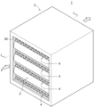
- FIG. 9 is a perspective view of a modified example of a suction rotor.
- FIG. 10(A) is a perspective view of a conventional dehumidification device, and
- FIG. 10(B) is a front view of a conventional adsorption rotor.
- the adsorption filter 1 is used primarily for dehumidification in which water in a gas to be processed, such as outside air, is adsorbed by an adsorbent and removed from the gas to be processed.
- 4 to 6 show a schematic configuration of the suction rotor 10 or the suction processing apparatus 100 according to an embodiment of the present disclosure.
- the adsorption treatment device 100 is a device that continuously removes moisture from the gas to be treated by supplying the gas to be treated to a rotating adsorption rotor 10, and a desiccant type dehumidification device is an example of its application. I can do it.
- the adsorption filter 1, adsorption rotor 10, and adsorption processing apparatus 100 of this embodiment are particularly suitable for dehumidifying a large amount of gas to be processed in buildings, condominiums, hospitals, factories, commercial facilities, and the like. Note that the use of the adsorption filter 1, adsorption rotor 10, and adsorption processing device 100 of this embodiment is not limited to dehumidification.
- an adsorption filter 1 houses an adsorption element 2 in which an adsorbent is supported on a base material made of nonwoven fabric (hereinafter referred to as "nonwoven fabric base material"), and an adsorption element 2. It includes a casing 3 and a support body 4 that holds the shape of the adsorption element 2.
- the casing 3 has a rectangular parallelepiped outer shape in this embodiment, although it is not particularly limited.
- the inside of the casing 3 is a cavity having a rectangular parallelepiped shape.
- the casing 3 has an opening communicating with an internal cavity on a pair of mutually opposing surfaces among the six surfaces.
- a pair of mutually opposing openings in the casing 3 are gas flow ports 30 .
- the gas to be treated and the regeneration gas are introduced into the casing 3 through one gas flow port 30 and are discharged from the casing 3 through the other gas flow port 30.
- the pair of gas flow ports 30 are not particularly limited, but in this embodiment, both have a rectangular outer shape and the same size.
- At least one of the four sides on which the pair of gas flow ports 30 are not formed is a removable lid or an openable lid. Thereby, the adsorption element 2 can be easily taken in and out of the casing 3.
- the material of the casing 3 is not particularly limited as long as the casing 3 exhibits sufficient strength and heat resistance during use; for example, metal materials such as stainless steel and aluminum, as well as acrylic, bakelite, melanin, etc. Examples include resin materials.
- the size of the casing 3 is appropriately set depending on the number and size of the adsorption elements 2 accommodated in the casing 3.
- the number of adsorption elements 2 accommodated in the casing 3 is one in this embodiment, it may be plural.
- a partition plate (not shown) is provided in the casing 3 and arranged adjacently. It is preferable to interpose a partition plate between the two adsorption elements 2. Thereby, it is possible to suppress the adsorption elements 2 from coming into contact with each other or rubbing against each other within the casing 3.
- the adsorption element 2 is housed in the casing 3 in close contact with the inner surface of the casing 3.
- the adsorption element 2 is formed into a pleat shape from a strip having a predetermined width, thickness, and length.
- the adsorption element 2 has a shape in which the strip-like material is folded in a zigzag manner, and is folded over and over again, and the shape is maintained.
- the adsorption element 2 includes a first bent portion 20 that protrudes convexly in one direction, a second bent portion 21 that protrudes convexly in another direction opposite to the one direction, and a first bent portion 20. and/or a straight portion 22 continuous to the second bent portion 21.
- the number of folded layers of the adsorption element 2 is not particularly limited, as long as it includes at least one first folded part 20 and at least one second folded part 21.
- the adsorption element 2 is housed in the casing 3 so that the gas to be treated and the regenerating gas introduced into the casing 3 cross over the adsorption element 2 and pass through the adsorption element 2 with low pressure loss.
- the first bent portion 20 faces toward one gas flow port 30 of the casing 3
- the second bent portion 21 faces toward the other gas flow port 30 of the casing 3. It is housed in the casing 3 so that the plane passing through the apex of each first bent part 20 and the plane passing through the apex of each second bent part 21 are perpendicular to the ventilation direction F. There is.
- the gas to be treated and the regenerating gas introduced into the casing 3 may cross the first bent portion 20 and the second bent portion 21 of the adsorption element 2, or may cross the first bent portion 20 and the second bent portion 21 of the adsorption element 2.
- the flow changes direction toward the straight portion 22 between the bent portions 21 and crosses it, and passes through the adsorption element 2 . Therefore, in the adsorption element 2, the gas to be treated and the regeneration gas are in good contact with not only the adsorbent on the surface side but also the adsorbent inside, and the contact efficiency between the gas to be treated and the regeneration gas and the adsorbent is high.
- the adsorption element 2 can effectively adsorb moisture in the gas to be treated using the adsorbent, so that dehumidification performance can be improved.
- the adsorption element 2 can effectively desorb moisture from the adsorbent with the regeneration gas, and the adsorption material can be regenerated with the regeneration gas at low temperature and low airflow, so the energy consumption during regeneration is reduced. Can improve efficiency.
- the adsorption element 2 is housed in the casing 3 such that the plurality of straight portions 22 are parallel or substantially parallel to the ventilation direction F (direction from one gas distribution port 30 of the casing 3 to the other gas distribution port 31). ing. Therefore, compared to the case where the adsorption element 2 is housed in the casing 3 so that the plurality of straight parts 22 are perpendicular to the ventilation direction F, when the gas to be treated or the regeneration gas passes through the adsorption element 2, Pressure loss can be reduced.
- the size of the adsorption element 2, that is, the height, width, and length are not particularly limited.
- the length of the adsorption element 2 (the size in the direction (depth direction) from one gas distribution port 30 to the other gas distribution port 31, and the length from the tip of the first bent portion 20 to the second bent portion
- the length (to the tip of the portion 21) is preferably 100 mm or more and 500 mm or less, more preferably 150 mm or more and 350 mm or less. Since the length of the adsorption element 2 is 100 mm or more, the adsorption element 2 can adsorb moisture on a large amount of gas to be treated. By setting the length of the adsorption element 2 to 500 mm or less, it is possible to suppress the adsorption rotor 10 from increasing in size.
- the adsorbent that constitutes the adsorption element 2 is a porous metal complex (MOF).
- Porous metal complexes (or porous coordination polymers) are porous structures that are self-assembled by combining metal ions that can take various coordination forms and organic ligands that have two or more coordination sites. It is the material.
- a framework structure is constructed by cross-linking metal ions that serve as nodes with organic ligands, and the voids within this framework act as spaces for absorbing water.
- Porous metal complexes are usually synthesized by reaction in solution. That is, a crystalline compound can be obtained by dissolving a compound having a metal ion source and an organic ligand in a solvent such as water and/or an organic solvent and heating the solution. Immediately after synthesis, solvent molecules are included within the lattice of the framework, but by removing these solvent molecules, it becomes a porous material.
- Porous metal complexes have a higher specific surface area and a sharper pore distribution than inorganic porous materials such as silica gel, zeolite, and activated carbon, so they can adsorb water in the gas to be treated at a faster rate and with less adsorption. It is characterized by the large amount of water it can produce. In addition, since it is possible to adsorb and desorb moisture with a weak bonding force, the adsorption heat generated when adsorbing moisture in the gas to be treated is small, and the adsorbed moisture can be desorbed even at low regeneration gas temperatures. Therefore, it has the characteristic that the energy required for reproduction is low.
- Metal ions constituting the porous metal complex are not particularly limited, but include, for example, titanium ions, manganese ions, iron ions, cobalt ions, nickel ions, copper ions, zinc ions, aluminum ions, zirconium ions, etc. can be mentioned.
- titanium ions, iron ions, manganese ions, copper ions, zinc ions, aluminum ions, and zirconium ions, which have low toxicity, can be preferably mentioned in consideration of environmental pollution.
- Examples of the compound having an organic ligand include, but are not limited to, terephthalic acid, isophthalic acid, 2-amino terephthalic acid, 2,5-diaminoterephthalic acid, 2,5-dihydroxyterephthalic acid, 1 , 4-naphthalenedicarboxylic acid, 2,6-naphthalenedicarboxylic acid, 4,4'-biphenyldicarboxylic acid, 3,3'-biphenyldicarboxylic acid, fumaric acid, 1H-pyrazole-3,5-dicarboxylic acid, 2,5 - dicarboxylic acids such as furandicarboxylic acid; tricarboxylic acids such as trimesic acid; tetracarboxylic acids such as azobenzene-3,3'-5,5'-tetracarboxylic acid; and imidazoles such as 2-methylimidazole. .
- Porous metal complexes are not particularly limited, but include, for example, porous metal complexes composed of aluminum ions and 2,5-furandicarboxylic acid, aluminum ions and 1H-pyrazole-3,5-dicarboxylic acid. porous metal complexes composed of iron ions and terephthalic acid; porous metal complexes composed of iron ions and trimesic acid; porous metal complexes composed of titanium ions and terephthalic acid.
- a porous metal complex composed of zirconium ions and terephthalic acid a porous metal complex composed of zirconium ions and fumaric acid, a porous metal complex composed of zirconium ions and 2-aminoterephthalic acid, a porous metal complex composed of zirconium ions and 2-aminoterephthalic acid, titanium ions and -Porous metal complex composed of aminoterephthalic acid, iron ion and porous metal complex composed of azobenzene-3,3'-5,5'-tetracarboxylic acid, aluminum ion and 1H-pyrazole-3,5 - porous metal complexes composed of dicarboxylic acids, etc. Even if the porous metal complexes are the same, the BET specific surface area of these porous metal complexes varies depending on the synthesis method and purity.
- the porous metal complex is not particularly limited, but preferably has open metal sites from the viewpoint of exhibiting higher moisture adsorption performance. Open metal sites exhibit high adsorption activity. Therefore, a porous metal complex having open metal sites has a very high rate of adsorption of moisture in the gas to be treated, and exhibits higher moisture adsorption performance than other porous metal complexes.
- One embodiment of the open metal site is, for example, an embodiment in which the metal ion is coordinately unsaturated and has at least one vacant site in its coordination state, that is, a coordinately unsaturated site.
- a porous metal complex having coordination unsaturated sites is one in which the ligand of the metal ion (Fe ion in Figure 7) is unsaturated, and the metal ion has one or more vacant coordination child (vacant site). Water molecules are adsorbed to these empty sites. Therefore, by using a porous metal complex having coordination unsaturated sites as an adsorbent, water in the gas to be treated can be effectively adsorbed, and high dehumidification performance for the gas to be treated can be exhibited.
- Porous metal complexes having coordination unsaturated sites include, but are not limited to, porous metal complexes composed of iron ions and azobenzene-3,3'-5,5'-tetracarboxylic acid (PCN250 or MIL127).
- chromium and terephthalic acid An example is a porous metal complex (MIL101) composed of an acid, and among these, PCN250 is preferable because it has a fast adsorption/desorption rate and uses a metal with low water resistance and toxicity.
- porous metal complexes having higher moisture adsorption performance include porous metal complexes having a hydroxyl group (OH-) near the metal.
- a porous metal complex having a hydroxy group near the metal has a hydroxy group (OH-) in the metal core unit, as shown in FIG.
- the porous metal complex has a hydroxyl group in the metal core unit, it exhibits excellent adsorption activity for water molecules. Therefore, a porous metal complex having a hydroxyl group in the metal core unit has a very high rate of adsorption and desorption of moisture in the gas to be treated, and exhibits higher moisture adsorption performance than other porous metal complexes. Therefore, by using a porous metal complex having a hydroxyl group in the metal core unit as an adsorbent, water in the gas to be treated can be effectively adsorbed, and high dehumidification performance for the gas to be treated can be exhibited.
- the metal core unit refers to a metal cluster that constitutes a porous metal complex represented by MxOyHz (x, y are integers other than 0, z is an integer including 0).
- Some of the oxygen atoms in the metal core unit MxOyHz are carboxyl group oxygen atoms of organic ligands, and the metal core unit forms a framework by sharing oxygen atoms with the organic ligands.
- porous metal complex having a hydroxyl group in the metal core unit examples include, but are not particularly limited to, a porous metal complex composed of zirconium ions and fumaric acid (MOF801), aluminum ions and 1H-pyrazole-3,5-dicarboxylic acid, etc.
- a porous metal complex composed of an acid.
- the adsorption filter 1 using the above-mentioned porous metal complex having open metal sites or a porous metal complex having a hydroxyl group in the metal core unit as an adsorbent can generate air with low humidity, and is therefore suitable for use in clean rooms, for example. It can be suitably used in a low dew point type dehumidification device.
- the shape of the porous metal complex is not particularly limited, and can be in various shapes such as powder or granules.
- the adsorbent may contain one or more porous metal complexes.
- the size of the adsorbent is not particularly limited, but is preferably 0.5 ⁇ m or more and 150 ⁇ m or less, more preferably 1 ⁇ m or more and 100 ⁇ m or less.
- the size of the adsorbent is 0.5 ⁇ m or more, it is possible to make it difficult for the adsorbent to fall off in the adsorption element 2, and it is possible to increase the contact efficiency of the adsorbent with the gas to be treated or regenerated gas. .
- the size of the adsorbent can be measured by the D50 value of a laser diffraction particle size analyzer or the average particle diameter by a scanning electron microscope.
- the pores of the adsorbent may be one-dimensional pores or three-dimensional pores, but from the viewpoint that the adsorption rate of moisture in the gas to be treated is fast and it is easy to adsorb moisture.
- the use of porous metal complexes having one-dimensional pores and open metal sites is preferred.
- porous metal complexes having one-dimensional pores include the above-mentioned MOF74 and MOF303.
- examples of porous metal complexes having open metal sites include the above-mentioned MOF74 and PCN250.
- the crystallite size of the adsorbent is small in order to easily adsorb moisture to the inside of the pores.
- MOF801 mentioned above can be cited as an example.
- the adsorbent is not particularly limited, but preferably is a porous metal complex having a pore diameter of 3.0 ⁇ or more and 10 ⁇ or less, more preferably 3.5 ⁇ or more and 8 ⁇ or less.
- a porous metal complex with a pore diameter of 3.0 ⁇ or more and 10 ⁇ or less has good adsorption performance and can easily desorb adsorbed water from the adsorbent during regeneration.
- the pore diameter of the adsorbent can be obtained by measuring the cage diameter or window diameter of the pores by X-ray structural analysis.
- the specific surface area of the adsorbent measured by the BET method is not particularly limited, but is preferably 200 m 2 /g or more and 2500 m 2 /g or less, more preferably 300 m 2 /g or more. It is 2000 m 2 /g or less.
- BET specific surface area is not particularly limited, but is preferably 200 m 2 /g or more and 2500 m 2 /g or less, more preferably 300 m 2 /g or more. It is 2000 m 2 /g or less.
- the content of the adsorbent in the adsorption element 2 is not particularly limited, but is preferably 15% by mass or more and 80% by mass or less, more preferably 20% by mass or more and 70% by mass or less.
- the content of the adsorbent is 15% by mass or more, the efficiency of contact between the gas to be treated or the regeneration gas and the adsorbent can be increased.
- By having an adsorbent content of 80% by mass or less it is possible to make it difficult for the adsorbent to fall off in the adsorption element 2, and to reduce the pressure loss when the gas to be treated or the regeneration gas passes through the adsorption element 2. can be reduced.
- the adsorbent is not particularly limited, it is preferable to impregnate water vapor or water into its pores before supporting it on a nonwoven fabric base material by adhesion with a binder, which will be described later. This prevents the binder from existing in the pores of the adsorbent and clogging the pores, thereby suppressing the deterioration of the adsorption performance of the moisture in the gas to be processed by the adsorbent in the adsorption element 2. I can do that.
- the adsorbent is not particularly limited, the adsorbent may have adsorption performance for carbon dioxide and aldehydes such as formaldehyde and acetaldehyde by supporting an amine compound on a porous metal complex.
- the base material constituting the adsorption element 2 is a single nonwoven fabric or a laminate of multiple nonwoven fabrics.
- the fibers constituting the nonwoven fabric are not particularly limited, and include, for example, phenolic resin fibers, polyphenylene ether fibers, flame-resistant polyphenylene ether fibers, polyacrylonitrile fibers, flame-resistant polyacrylonitrile fibers, pitch fibers, flame-resistant pitch fibers, and aramid fibers. Examples include PET fibers, glass fibers, ceramic fibers, carbon fibers, activated carbon fibers, stainless steel fibers, aluminum fibers, and other metal fibers.
- nonwoven fabrics made of phenolic fibers phenolic fiber nonwoven fabrics
- nonwoven fabrics made of polyphenylene ether fibers polyphenylene ether fiber nonwoven fabrics
- nonwoven fabrics made of flame resistant polyphenylene ether fibers flame resistant polyphenylene ether fiber nonwoven fabrics
- flame resistant acrylonitrile fibers flame resistant polyphenylene ether fiber nonwoven fabrics
- flame resistant acrylonitrile fibers flame resistant polyphenylene ether fiber nonwoven fabrics
- flame resistant acrylonitrile fibers flame resistant polyphenylene ether fiber nonwoven fabrics
- flame resistant acrylonitrile fibers flame resistant polyphenylene ether fiber nonwoven fabrics
- flame resistant acrylonitrile fibers flame resistant polyphenylene ether fiber nonwoven fabrics
- flame resistant acrylonitrile fibers flame resistant polyphenylene ether fiber nonwoven fabrics
- flame resistant acrylonitrile fibers flame resistant polyphenylene ether fiber nonwoven fabrics
- flame resistant acrylonitrile fibers flame resistant polyphenylene ether fiber nonwoven
- the cross-sectional shape of the above-mentioned fibers may be a general shape such as a circle or an ellipse, or an irregular shape such as a star shape or a Y-shape.
- the average fiber diameter of the fibers constituting the nonwoven fabric is not particularly limited, but is preferably 10 ⁇ m or more and 100 ⁇ m or less, more preferably 15 ⁇ m or more and 60 ⁇ m or less.
- the average fiber diameter is 10 ⁇ m or more, the gaps between the fibers of the nonwoven fabric base material do not become too narrow, so that the pressure loss when the gas to be treated or the regeneration gas passes through the adsorption element 2 can be reduced.
- By having an average fiber diameter of 100 ⁇ m or less it is possible to make it difficult for the adsorbent to fall off in the adsorption element 2.
- the average fiber diameter is determined by observing a microscopic image of the fiber using a scanning electron microscope (product name SU1510, manufactured by Hitachi High-Technologies), reading the diameters of 100 or more fibers from the microscopic image, and averaging the read fiber diameters. can be found.
- a scanning electron microscope product name SU1510, manufactured by Hitachi High-Technologies
- the method for producing the nonwoven fabric base material is not particularly limited, and examples include spunbond method, melt blow method, spunlace method, needle punch method, thermal bond method, and chemical bond method. Among these, it is preferable to use a needle-punched nonwoven fabric produced by the needle-punching method because it provides suitable voids that can support the adsorbent.
- the thickness of the nonwoven fabric base material is: Although not particularly limited, it is preferably 4 mm or more and 50 mm or less, more preferably 10 mm or more and 40 mm or less.
- a thickness of the nonwoven fabric base material is 4 mm or more, sufficient strength of the adsorption element 2 can be ensured.
- the thickness of the nonwoven fabric base material is 50 mm or less, the adsorption element 2 can be easily processed into a pleated shape, and pressure loss when the gas to be treated or the regeneration gas passes through the adsorption element 2 can be reduced.
- the basis weight of the nonwoven fabric base material (if the nonwoven fabric base is a single piece of nonwoven fabric, the basis weight of the nonwoven fabric alone; if the nonwoven fabric base material is a laminate of multiple nonwoven fabrics, the total basis weight of the laminate) is: Although not particularly limited, it is preferably 300 g/m 2 or more and 5000 g/m 2 or less, more preferably 600 g/m 2 or more and 4000 g/m 2 or less.
- the basis weight of the nonwoven fabric base material is 300 g/m 2 or more, the strength of the adsorption element 2 can be sufficiently ensured, and the contact efficiency between the gas to be treated or the regeneration gas and the adsorbent can be increased.
- pressure loss when the gas to be treated or the regeneration gas passes through the adsorption element 2 can be reduced.
- the adsorption element 2 is manufactured by the procedure described below. First, an adsorbent and a binder are dispersed in water to produce a slurry.
- the binder is not particularly limited as long as it can bond the adsorbent to the nonwoven fabric substrate, but it is preferable to use a water-repellent binder.
- water-repellent binders include organic binders having structural units derived from styrene and/or acrylic.
- the form of the binder is not particularly limited, it is preferable to use an emulsion form.
- the contents of the adsorbent and binder in the slurry are not particularly limited, but the adsorbent is, for example, 5% by mass or more and 50% by mass or less, and the binder is, for example, 1% by mass or more and 40% by mass or less.
- the temperature of the slurry is not particularly limited, but is, for example, 5° C. or higher and 35° C. or lower.
- the nonwoven fabric base material is sufficiently immersed in the slurry to incorporate the slurry not only onto the surface of the nonwoven fabric base material but also into its interior. Then, the nonwoven fabric base material that has been immersed in the slurry is squeezed under pressure to allow the slurry to sufficiently penetrate inside the nonwoven fabric base material, and unnecessary slurry is removed from the nonwoven fabric base material to form a slurry that is applied to the nonwoven fabric base material. Adjust amount.
- the proportion of the slurry applied to the nonwoven fabric base material is not particularly limited, but is preferably 20% by mass or more and 95% by mass or less, more preferably 25% by mass or more and 90% by mass or less.
- the squeezed nonwoven fabric base material is dried to remove moisture contained in the nonwoven fabric base material.
- the drying temperature is not particularly limited, but is, for example, 5° C. or higher and 200° C. or lower, and drying can be performed using air at about 20° C. and low humidity, for example.
- the adsorption element 2 is manufactured by forming the nonwoven fabric base material carrying the dried adsorbent into a pleat shape.
- the nonwoven fabric base material is formed into a pleat shape in a semi-dry state where the nonwoven fabric base material is completely dried. The nonwoven substrate may then be completely dried.
- the slurry penetrates into the inside of the nonwoven fabric base material, and the slurry adheres not only to the fibers on the surface side of the nonwoven fabric base material but also to the fibers inside the nonwoven fabric base material. , the slurry between the fibers is extruded and removed from the nonwoven substrate.
- the adsorbent is supported on the surface of the constituent fibers throughout the nonwoven fabric base material by adhesion with the binder, while being suppressed from existing between the fibers of the nonwoven fabric base material.
- the air permeability of the adsorption element 2 is increased, and pressure loss when the gas to be treated and the regeneration gas pass through the adsorption element 2 can be reduced.
- the support body 4 is provided within the casing 3 in order to hold the pleated adsorption element 2 in a stable state without losing its shape.
- the support body 4 is not particularly limited, but in this embodiment, it is made of a net-like body in which a corrugated wire mesh 41 is sandwiched between two flat wire meshes 40.
- the support body 4 is sandwiched between a plurality of straight portions 22 of the pleated adsorption element 2 arranged at intervals.
- the thickness of the support 4 is not particularly limited, but is, for example, 5 mm or more and 25 mm or less.
- the material of the support 4 is not particularly limited as long as it has sufficient strength, heat resistance, chemical resistance, etc. under the usage conditions of the adsorption filter 4, and examples include metal materials such as stainless steel and aluminum, as well as acrylic and Bakelite. Examples include resin materials such as , melanin, and the like.
- the support body 4 does not necessarily need to be composed of a plurality of net-like bodies, and its form is not limited as long as it can hold the pleated adsorption element 2 in a stable state without losing its shape.
- the adsorption filter 1 having the above structure preferably has a pressure loss of 2 kPa or less, more preferably 1.5 kPa or less, and even more preferably 1.0 kPa or less. Thereby, the gas to be treated can be efficiently passed through the adsorption filter 1.
- the pressure loss can be determined by setting the adsorption filter 1 in a ventilation pressure loss measurement jig and measuring the pressure loss when ventilation is passed through one gas flow port 30 at a wind speed of 2.0 m/s.
- the suction rotor 10 has a hollow, generally annular shape having an inner diameter and an outer diameter when viewed in cross section, and has a predetermined height.
- the suction rotor 10 is installed in the processing chamber 101 so as to be rotationally driven around the rotation axis L.
- the adsorption rotor 10 is installed in the processing chamber 101 so that the rotation axis thereof faces vertically so that the gas to be processed is introduced and discharged at each of the inner and outer peripheries.
- the rotation axis of the suction rotor 10 passes through the center in a cross-sectional view.
- the adsorption rotor 10 includes a plurality of the above-mentioned adsorption filters 1.
- the plurality of adsorption filters 1 are arranged along the circumferential direction around the rotation axis of the adsorption rotor 10.
- the plurality of adsorption filters 1 are arranged such that the pair of gas flow ports 30 of the casing 3 face the outer and inner peripheries of the adsorption rotor 10 .
- the plurality of adsorption filters 1 are arranged in a fixed state so as to form a plurality of vertical stages (in this embodiment, two stages above and below), they do not necessarily need to be arranged in a plurality of stages.
- the suction rotor 10 includes a pair of discs 5A and 5B made of stainless steel, for example.
- a pair of disks 5A and 5B sandwich the plurality of adsorption filters 1 from above and below.
- the pair of disks 5A and 5B are hollow and generally annular in shape and have an inner diameter and an outer diameter when viewed in cross section.
- the pair of disks 5A and 5B are arranged parallel to each other so that the rotation axis of the suction rotor 10 passes through the center in a cross-sectional view.
- the central openings of the pair of disks 5A, 5B communicate with the inner cavities of the plurality of adsorption filters 1 arranged in a cylindrical shape.
- the suction rotor 10 includes a plurality of partitions 7 that partition the space between the pair of disks 5A, 5B into a plurality of mutually independent spaces in the circumferential direction.
- An adsorption filter 1 is housed airtightly between two adjacent partitions 7 between a pair of disks 5A and 5B with a sealing member 6 made of, for example, rubber interposed therebetween.
- the plurality of partitions 7 extend in the radial direction from the inner circumferential edge to the outer circumferential edge of the pair of disks 5A, 5B, and are arranged at intervals in the circumferential direction. Further, the plurality of partitions 7 are erected between the pair of disks 5A and 5B.
- the gas to be treated flowing in from the inner or outer circumference of the adsorption rotor 10 passes through each adsorption filter 1 between the pair of disks 5A and 5B and between the plurality of partitions 7.
- the partition 7 includes a main body portion 70 and a pair of seal portions 71A and 71B.
- the main body portion 70 is made of stainless steel, for example.
- the upper and lower ends of the main body portion 70 are in airtight contact with the pair of discs 5A and 5B.
- the seal parts 71A and 71B are made of rubber, for example.
- the seal portions 71A and 71B are attached to both side edges of the main body portion 70 using, for example, adhesive.
- the upper and lower ends of the seal portions 71A, 71B are in airtight contact with the pair of disks 5A, 5B.
- a portion of the seal portion 71A attached to the inner side edge of the main body portion 70 protrudes inward from the inner peripheral edges of the pair of discs 5A and 5B.
- a portion of the seal portion 71B attached to the outer side edge of the main body portion 70 protrudes outward from the outer peripheral edge of the pair of disks 5A, 5B.
- the adsorption processing apparatus 100 includes the above-mentioned adsorption rotor 10 installed in a processing chamber 101.
- the suction rotor 10 is rotationally driven around the rotation axis L by receiving the rotational driving force of the motor 9, for example.
- the adsorption rotor 10 moves a portion in the circumferential direction to an adsorption zone 102 where the gas to be processed is adsorbed, and the remaining portion in the circumferential direction moves to the adsorption zone 102 where the adsorption process is performed using regeneration gas. Move to zone 103.
- the adsorption processing apparatus 100 includes a flow path through which a gas to be processed supplied into the processing chamber 101 flows into and out of an adsorption filter 1 that is a part of an adsorption rotor 10 that rotates within the processing chamber 101, and A supply flow path forming member 8 is provided for forming a flow path through which regeneration gas flows into and out of another part of the adsorption filter 1 of the adsorption rotor 10.
- the supply flow path forming member 8 includes a first flow path forming member 80 , a second flow path forming member 81 , a third flow path forming member 82 , and a zone dividing member 83 .
- the first flow path forming member 80 has a cylindrical shape, and the gas to be treated flows through the inside thereof.
- the first flow path forming member 80 is provided so as to penetrate through the ceiling of the processing chamber 101, and the lower end of the first flow path forming member 80 is in contact with the disc 5A of the adsorption rotor 10 in an airtight manner so that the disc 5A can rotate. There is.
- the inner cavity of the first flow path forming member 80 communicates with the inner cavity of the adsorption rotor 10 via the central opening of the disk 5A.
- the first flow path forming member 80 introduces the gas to be treated, which flows from the outside of the adsorption rotor 10 into the processing chamber 101, passes through the adsorption filter 1, and flows out into the inside of the adsorption rotor 10, into the inside through an opening 800 at the lower end. , and is discharged to the outside of the processing chamber 101 from the opening 801 at the upper end.
- the second flow path forming member 81 has a cylindrical shape, and the regeneration gas flows through the inside thereof.
- One end of the second flow path forming member 81 is bent into an L shape and is provided so as to penetrate the side wall of the first flow path forming member 80 .
- An opening 810 at one end of the second flow path forming member 81 is located outside the processing chamber 101 and introduces the regeneration gas into the second flow path forming member 81 .
- the other end of the second flow path forming member 81 is arranged in a cavity inside the adsorption rotor 10 .
- the opening 811 at the other end of the second flow path forming member 81 is parallel to the vertical direction and faces the inner periphery of the adsorption rotor 10, and is connected to the communication port 30 of the adsorption filter 1 that moves in the circumferential direction as the adsorption rotor 10 rotates. to oppose.
- the opening 811 at the other end of the second flow path forming member 81 discharges the regeneration gas flowing inside the second flow path forming member 81 toward the inner periphery of the adsorption filter 1 of the adsorption rotor 10 .
- the third flow path forming member 82 has a cylindrical shape, and the regeneration gas flows through the inside thereof.
- One end of the third flow path forming member 82 is disposed outside the outer periphery of the adsorption rotor 10 .
- the opening 820 at one end of the third flow path forming member 82 is parallel to the vertical direction and faces the outer periphery of the adsorption rotor 10, and the opening 820 at the other end of the second flow path forming member 81 and the adsorption rotor 10 are sandwiched therebetween. face each other.
- the opening 820 at one end of the third flow path forming member 82 faces the flow port 30 of the adsorption filter 1 that moves in the circumferential direction due to the rotation of the adsorption rotor 10.
- the opening 821 at one end of the third flow path forming member 82 introduces the regenerating gas that flows from the inside of the adsorption rotor 10, passes through the adsorption filter 1, and flows out to the outside into the third flow path forming member 82.
- the other end of the third flow path forming member 82 is provided so as to penetrate the side wall of the processing chamber 101 .
- the opening 821 at the other end of the third flow path forming member 82 is located outside the processing chamber 101 and discharges the regeneration gas flowing inside the third flow path forming member 82 to the outside of the processing chamber 101 .
- the zone dividing member 83 includes a pair of inner curved portions 830 provided at the other end of the second channel forming member 81 and a pair of outer curved portions 831 provided at one end of the third channel forming member 82. including.
- the inner curved portion 830 is curved so as to face the inner circumference of the suction rotor 10
- the outer curved portion 831 is curved so as to face the outer circumference of the suction rotor 10 .
- the curved portions 831 are parallel to each other.
- the upper and lower ends of the inner curved portion 830 and the outer curved portion 831 are in contact with the discs 5A, 5B of the suction rotor 10 in an airtight manner so that the discs 5A, 5B can rotate.
- the plurality of suction filters 1 and the plurality of partitions 7 move in the circumferential direction of the suction rotor 10.
- the inner seal part 71A and the outer seal part 71B of some of the partitions 7 are in airtight contact with the inner curved part 830 and the outer curved part 831 on the upstream side in the rotational direction, respectively.
- the inner seal part 71A and the outer seal part 71B of some of the partitions 7 move while being in airtight contact with the inner curved part 830 and the outer curved part 831 on the downstream side in the rotational direction, respectively.
- the adsorption filter 1 which is moving to the adsorption zone 102 which does not communicate with the third flow path forming member 82 and thus becomes an adsorption zone 102 .
- the plurality of adsorption filters 1 of the adsorption rotor 10 alternately move between the adsorption zone 102 and the desorption zone 103 as the adsorption rotor 10 rotates.
- the adsorption processing of moisture in the gas to be processed will be explained.
- the gas to be treated is introduced into the adsorption filter 1 that is moving to the adsorption zone 102 of the adsorption rotor 10.
- the adsorption filter 1 adsorbs moisture in the gas to be treated using an adsorbent while the gas to be treated passes through the adsorption element 2 . Thereby, the gas to be processed is dehumidified.
- the dehumidified gas to be processed is discharged from the inner periphery of the adsorption rotor 10 , introduced into the first flow path forming member 80 , and discharged to the outside of the processing chamber 101 by the first flow path forming member 80 .
- a regeneration gas such as heated air is supplied from the inner circumference of the adsorption rotor 10 in the desorption zone 103 in the processing chamber 101 by the second flow path forming member 81, and the regeneration gas is moved to the desorption zone 103 of the adsorption rotor 10. into the adsorption filter 1.
- the adsorption filter 1 when the regeneration gas passes through the adsorption element 2, moisture adsorbed by the adsorbent is desorbed by the regeneration gas. Thereby, the adsorption element 2 of the adsorption filter 1 is regenerated. Then, the regeneration gas containing moisture is discharged from the outer periphery of the adsorption rotor 10, introduced into the third flow path forming member 82, and discharged to the outside of the processing chamber 101 by the third flow path forming member 82.
- the adsorption process is performed on the gas to be treated by the adsorption filter 1 that moves to the adsorption zone 102 as the adsorption rotor 10 rotates, and the adsorption process that moves to the desorption zone 103 after the adsorption process 1 is subjected to a desorption process for the adsorbed moisture.
- the suction rotor 10 rotates around the rotation axis L, the suction filter 1 alternately moves between the suction zone 101 and the desorption zone 103. Therefore, in the adsorption processing apparatus 100, the adsorption of moisture in the gas to be treated and the regeneration process of the adsorption filter 1 that has adsorbed the moisture are performed continuously.
- the pleated adsorption element 2 has its first bent portion 20 connected to one gas flow port 30 of the casing 3. It is housed in the casing 3 with the second bent portion 21 facing the other gas flow port 30 of the casing 3 . Therefore, the gas to be treated and the regeneration gas pass through the adsorption element 2 while intersecting a portion of the adsorption element 2 (the bent portions 20 and 21 and the straight portion 22).
- the gas to be treated and the regeneration gas come into good contact not only with the adsorbent supported on the surface side of the adsorption element 2 but also with the adsorbent supported inside the adsorption element 2. Therefore, according to the above-described adsorption filter 1, adsorption rotor 10, and adsorption processing apparatus 100, the contact efficiency between the gas to be treated and the adsorbent is high, so that the dehumidification performance can be improved. In addition, the contact efficiency between the regenerating gas and the adsorbent is high, and moisture can be desorbed from the adsorbent with the regenerating gas at a lower temperature and with a lower air volume than when the conventional adsorption element has a honeycomb structure. Therefore, according to the above-described adsorption filter 1, adsorption rotor 10, and adsorption processing device 100, energy efficiency during regeneration can be improved.
- the adsorbent is carried on the surface of the fibers constituting the nonwoven fabric base material, and the adsorbent material is supported on the surface of the fibers constituting the nonwoven fabric base material, and the adsorbent material is supported on the surface of the fibers constituting the nonwoven fabric base material.
- Existence is suppressed. Thereby, the air permeability of the adsorption element 2 is increased, and pressure loss when the gas to be treated and the regeneration gas pass through the adsorption element 2 can be reduced.
- the gas to be treated or regenerated gas can be passed through with low pressure loss. can be done.
- the porous metal complex used in the adsorption material has a high adsorption speed of moisture in the air and a small amount of moisture that can be adsorbed. Since there is a large amount of water, it is possible to adsorb more water in the gas to be treated than conventional and commonly used silica gel. Therefore, according to the above-described adsorption filter 1, adsorption rotor 10, and adsorption processing device 100, the dehumidification performance can be further improved.
- adsorption filter 1, adsorption rotor 10, and adsorption processing device 100 can be suitably used, for example, in a low dew point dehumidification device for a clean room.
- the porous metal complex used in the adsorption material has a lower temperature than the conventional and commonly used silica gel. Moisture can be desorbed from the adsorbent with regeneration gas. Therefore, according to the above-described adsorption filter 1, adsorption rotor 10, and adsorption processing device 100, energy efficiency during regeneration can be improved and energy saving is possible.
- the adsorbent is supported on the nonwoven fabric base material in the adsorption element 2 by adhesion with a binder, but as a modified example, the adsorbent is directly synthesized with the nonwoven fabric base material, so that the adsorbent is supported on the nonwoven fabric base material. You may let them.
- Direct synthesis of adsorbents onto nonwoven substrates involves (1) a layer-by-layer method by alternately immersing the nonwoven substrate in metal and ligand solutions; (2) synthesis of metal and ligands; There is a method in which a nonwoven fabric base material is synthesized by immersing it in a mixed solution, and in some cases, after the immersion, a skeleton is formed using heating, pressure, or microwaves.
- the adsorption rotor 10 is installed in the processing chamber 101 so that the rotation axis L points in the vertical direction; You may.
- the suction rotor 10 is formed by connecting a plurality of suction filters 1 arranged along the circumferential direction around the rotation axis L, as shown in FIG.
- the adsorption filter 1 includes an adsorption element 2 formed in a pleated shape and a casing 3 that accommodates the adsorption element 2, as in the embodiment described above.
- the casing 3 does not have a rectangular parallelepiped shape but a quadrangular prism shape with a trapezoidal cross section.
- the inside of the casing 3 is a cavity having a rectangular parallelepiped shape.
- gas flow ports 30 each communicating with an internal cavity are formed on a pair of trapezoidal faces facing each other.
- the adsorption element 2 is housed in the casing 3 in close contact with the inner surface of the casing 3.
- the adsorption filter 1 of the adsorption rotor 10 alternately moves between the adsorption zone 102 and the desorption zone 103 due to the rotation of the adsorption rotor 10.
- the adsorption zone 102 and the desorption zone 103 are separated by a flow path forming member (not shown).
- the gas to be treated that is supplied to the adsorption zone 102 crosses the adsorption element 2 of the adsorption filter 1 and passes through the adsorption element 2. Adsorbs moisture. Thereby, the gas to be processed is dehumidified.
- the regeneration gas supplied to the desorption zone 103 crosses the adsorption element 2 of the adsorption filter 1 and passes through the adsorption element 2, so that the moisture adsorbed by the adsorbent is transferred to the regeneration gas. It is attached and detached by. Thereby, the adsorption element 2 of the adsorption filter 1 is regenerated.
- FIG. 9 also provides the same actions and effects as the embodiment described above.
- the adsorption filter 1, adsorption rotor 10, and adsorption processing apparatus 100 of the embodiment shown in FIG. 9 can be suitably used, for example, in a factory, etc. to dehumidify a gas to be processed with a low air volume. Note that the use of the adsorption filter 1, adsorption rotor 10, and adsorption processing device 100 is not limited to dehumidification.
- adsorption filter of the present disclosure will be shown below to specifically explain the functions and effects, but the adsorption filter of the present disclosure is not limited to the following examples.
- Example 1 In Example 1, 2.7 kg of PCN250 (solid content 72%) was soaked overnight in 5.5 kg of water as an adsorbent, and then acrylic-styrene binder A (solid content 37%) 1 was soaked as a water-resistant binder. .0 kg was added to produce a 25% solids slurry. After immersing Kynor felt (fabric weight 600 g/m 2 , fineness 10 denier, thickness 6.0 mm) in the slurry as a nonwoven fabric, excess slurry was squeezed out from the nonwoven fabric, water was evaporated, and the nonwoven fabric carrying PCN250 was prepared. Obtained.
- Kynor felt fabric weight 600 g/m 2 , fineness 10 denier, thickness 6.0 mm
- this nonwoven fabric Four sheets of this nonwoven fabric are laminated to form a nonwoven fabric base material, and after folding the nonwoven fabric base material into a pleat shape, it is heated and dried at 130°C to form a pleat shape with a height of 250 mm, width of 250 mm, and length of 200 mm.
- An adsorption element was obtained.
- the content of PCN250 in the adsorption element was 45.5% by mass.
- PCN250 was produced by the following method. 0.5 g of Fe(NO 3 ) 3.9H 2 O and 0.1 g of azobenzene-3,3'-5,5'-tetracarboxylic acid were dissolved in 20 mL of N,N-dimethylformaldehyde and 10 mL of acetic acid. PCN250 was synthesized by heating at °C for 24 hours. As a result of nitrogen adsorption measurement of the PCN250 sample, the BET specific surface area was 1227 m 2 /g.
- Example 2 2.8 kg of MOF303 (solid content 70%) was soaked overnight in 5.6 kg of water as an adsorbent, and then acrylic-styrene binder A (solid content 37%) 1 was soaked as a water-resistant binder. .0 kg was added to produce a 25% solids slurry.
- Kynor felt (fabric weight: 600 g/m 2 , fineness: 10 denier, thickness: 6.0 mm) was immersed in the slurry as a nonwoven fabric, and then the excess slurry was squeezed out from the nonwoven fabric and the water was evaporated to form a nonwoven fabric carrying MOF303. Obtained.
- this nonwoven fabric Four sheets of this nonwoven fabric are laminated to form a nonwoven fabric base material, and after folding the nonwoven fabric base material into a pleat shape, it is heated and dried at 130°C to form a pleat shape with a height of 250 mm, width of 250 mm, and length of 200 mm.
- An adsorption element was obtained.
- the content of MOF303 in the adsorption element was 45.0% by mass.
- MOF303 was manufactured by the following method. 10.4 g (43.08 mmol) of AlCl 3.6H 2 O and 7.5 g (43.08 mmol) of 1H-pyrazole-3,5-dicarboxylic acid monohydrate were mixed with 720 mL of water and 2.6 g (65 mmol) of NaOH/30 mL of water. MOF303 was synthesized by dissolving it in water and heating it at 100°C for 24 hours. As a result of nitrogen adsorption measurement of the MOF303 sample, the BET specific surface area was 1181 m 2 /g.
- Example 3 2.4 kg of MOF801 (alkali treated, solid content 85%) was soaked overnight in 6.3 kg of water as an adsorbent, and then acrylic-styrene binder A (solid content) was soaked as a water-resistant binder. 37%) was added to produce a slurry with a solids content of 25%.
- Kynor felt fabric weight 600 g/m 2 , fineness 10 denier, thickness 6.0 mm
- MOF801 alkali treated
- This nonwoven fabric Four sheets of this nonwoven fabric are laminated to form a nonwoven fabric base material, and after folding the nonwoven fabric base material into a pleat shape, it is heated and dried at 130°C to form a pleat shape with a height of 250 mm, width of 250 mm, and length of 200 mm.
- An adsorption element was obtained.
- the content of MOF801 (alkali treated) in the adsorption element was 48.0% by mass.
- MOF801 (alkali treated) was produced by the following method. 200 g (0.62 mmol) of ZrOCl 2.8H 2 O and 72 g (0.62 mmol) of fumaric acid were dissolved in 2 L of N,N-dimethylformaldehyde and 700 mL of formic acid, and the mixture was heated at 130° C. for 6 hours to synthesize MOF801. The obtained MOF801 was suspended in water (pH 3.6), and 2 wt % sodium hydrogen carbonate water was added dropwise thereto until the pH exceeded 5. Thereafter, it was washed several times with pure water to obtain a MOF801 (alkali-treated) sample. As a result of nitrogen adsorption measurement of the MOF801 (alkali-treated) sample, the BET specific surface area was 600 m 2 /g.
- MOF303 was immersed in water as an adsorbent for 24 hours, and then filtered to obtain a MOF303 sample in which water molecules were adsorbed in the pores.
- This MOF303 sample is 80% by mass (excluding water molecules), 8% by mass of aramid fibers as non-fibrillated fibers, 5% by mass of aramid fibers as fibrillated fibers, and polyvinyl having a dissolution temperature in water of 70°C as an organic binder.
- Comparative Example 2 2.7 kg of A-type silica gel (Fuji Silica Gel A-type crushed manufactured by Fuji Silysia Chemical Co., Ltd., solid content 73%) was soaked overnight in 5.8 kg of water as an adsorbent, and then acrylic was added as a water-resistant binder. - 1.0 kg of styrenic binder A (solid content 37%) was added to produce a slurry with a solid content of 25%.
- Kynor felt (fabric weight: 600 g/m 2 , fineness: 10 denier, thickness: 6.0 mm) was immersed in the slurry as a non-woven fabric, and then the excess slurry was squeezed out from the non-woven fabric, and the water was evaporated to form a non-woven fabric carrying silica gel. Obtained.
- Four sheets of this nonwoven fabric are laminated to form a nonwoven fabric base material, and after folding the nonwoven fabric base material into a pleat shape, it is heated and dried at 130°C to form a pleat shape with a height of 250 mm, width of 250 mm, and length of 200 mm.
- An adsorption element was obtained.
- the content of silica gel in the adsorption element was 47.8% by mass.
- An adsorption filter in which the adsorption elements of Examples 1 to 3 and the adsorption elements of Comparative Examples 1 to 2 were each housed closely in a casing was installed in a dynamic water vapor adsorption/desorption evaluation tester, and the dehumidification performance was evaluated.
- the ratio of the flow rate of the treated gas (air) during dehumidification to the flow rate of the regeneration gas (air) during regeneration is set to 3:1, and the dehumidification is performed at a temperature of 20°C and an absolute humidity of 6.5 g/kg.
- DA a gas to be treated at a wind speed of 2 m/sec was supplied to the adsorption element to adsorb moisture in the gas to be treated.
- Regeneration is performed by supplying regeneration gas to the adsorption element from the opposite direction to that used during dehumidification, at a temperature of 80°C to 150°C, absolute humidity, and wind speed of 2 m/sec, to remove moisture from the adsorbent. was adsorbed. Dehumidification and regeneration were performed alternately multiple times, and the average value of the absolute humidity of the gas to be treated in which moisture had been adsorbed was measured as the dehumidification performance. The results are shown in Table 1. Table 1 also shows the reduction in energy consumption during regeneration for Examples 1 to 3 and Comparative Examples 1 to 2.
- Example 2 has better dehumidification performance than Comparative Example 1. Furthermore, it is confirmed that Example 1 can maintain high dehumidification performance even when the temperature of the regeneration gas (desorption temperature) is low. Based on these facts, pleated adsorption elements have a higher contact efficiency between the gas to be treated and the adsorbent than honeycomb-structured adsorption elements, so they can achieve good dehumidification performance with a small amount of adsorbent. It can be seen that since the contact efficiency between the regeneration gas and the adsorbent is high, water can be desorbed from the adsorbent with the regeneration gas at a low temperature, and the energy efficiency during regeneration is improved.
- Examples 1 to 3 can maintain high dehumidification performance with regeneration gas at a lower temperature than Comparative Example 2. is confirmed. Therefore, by using a porous metal complex as an adsorbent, it is possible to desorb water from the adsorbent with a regeneration gas at a lower temperature than by using silica gel as an adsorbent, and the energy used during regeneration is reduced. It can be seen that the amount can be reduced and energy can be saved.
- Adsorption filter 2 Adsorption element 3 Casing 9 Motor 10
- Adsorption rotor 20 First bent part 21 Second bent part 30
- Gas flow port 100 Adsorption treatment device 102
Abstract
Provided is an adsorption filter, an adsorption rotor, and an adsorption treatment device by which contact efficiency between an adsorption material and a gas to be treated or a recycled gas can be increased, dehumidification performance and energy efficiency when recycling can be improved, and energy can be better conserved when recycling in comparison to using silica gel as an adsorption material. Provided is an adsorption filter 1 that adsorbs moisture contained in a gas to be treated and comprises: a casing 3 having a pair of mutually opposing gas circulation ports 30; and an adsorption element 2 accommodated in the casing 3 and having an adsorption material supported on a nonwoven base material. The adsorption element 2 is formed in a pleated shape with first bent portions 20 facing one of the gas circulation ports 30 and second bent portions 21 facing the other gas circulation port 30, the first bent portions 20 each projecting in one direction in a protruding shape, and the second bent portions 21 each projecting in the other direction in a protruding shape. The adsorption material is a porous metal complex comprising metal ions and an organic ligand and is supported on the surface of fibers constituting the nonwoven base material.
Description
本開示は、吸着フィルター、吸着ロータ、及び吸着処理装置に関する。
The present disclosure relates to an adsorption filter, an adsorption rotor, and an adsorption processing device.
被処理ガス中の水分を吸着して被処理ガスの除湿を目的とした除湿装置は、工業用途、家庭用途を問わず広く用いられている。除湿装置として、図10に示すように、回転軸Lを中心にして回転可能な円柱形の吸着ロータ111を備えた除湿装置110が知られている(例えば特許文献1を参照)。
Dehumidifiers that aim to dehumidify a gas to be processed by adsorbing moisture in the gas to be processed are widely used in both industrial and domestic applications. As a dehumidifying device, as shown in FIG. 10, a dehumidifying device 110 is known that includes a cylindrical suction rotor 111 that is rotatable around a rotation axis L (see, for example, Patent Document 1).
吸着ロータ111は、一般的にハニカム構造の吸着素子112を備えている。吸着素子112は、例えば不織布基材にシリカゲルなどの吸着材を担持した吸着シートで形成されている。吸着シートは、平坦なライナーシート113Aと、長手方向に沿って凹凸が繰り返す波型とされたコルゲートシート113Bとを含む。吸着素子112は、ライナーシート113A及びコルゲートシート113Bを交互に径方向に積み重ねることで、径方向に直交する長さ方向に延びる多数の空隙114が密に並ぶハニカム構造とされている。
The adsorption rotor 111 generally includes an adsorption element 112 having a honeycomb structure. The adsorption element 112 is formed of, for example, an adsorption sheet in which an adsorbent such as silica gel is supported on a nonwoven fabric base material. The suction sheet includes a flat liner sheet 113A and a corrugated corrugated sheet 113B with repeated irregularities along the longitudinal direction. The adsorption element 112 has a honeycomb structure in which a large number of voids 114 extending in the length direction perpendicular to the radial direction are closely lined up by stacking liner sheets 113A and corrugated sheets 113B alternately in the radial direction.
吸着ロータ111は回転軸周りの周方向に沿って吸着ゾーン及び脱着ゾーンに区切られている。吸着ゾーンにおいては、例えば外気などの被処理ガスが吸着ロータ111に供給される。被処理ガスは、吸着ゾーンに位置する吸着素子112のそれぞれの空隙114を流れることで吸着素子112を通過するが、この際に被処理ガス中の水分が吸着材によって吸着される。これにより、被処理ガスが除湿される。脱着ゾーンにおいては、例えば高温空気などの再生ガスが吸着ロータ111に供給される。再生ガスは、脱着ゾーンに位置する吸着素子112のそれぞれの空隙114を流れて吸着素子112を通過するが、この際に吸着材から水分を脱着する。これにより、吸着材が再生される。
The suction rotor 111 is divided into a suction zone and a desorption zone along the circumferential direction around the rotating shaft. In the adsorption zone, a gas to be treated, such as outside air, is supplied to the adsorption rotor 111 . The gas to be treated passes through the adsorption elements 112 by flowing through the gaps 114 of each of the adsorption elements 112 located in the adsorption zone, and at this time, moisture in the gas to be treated is adsorbed by the adsorbent. Thereby, the gas to be processed is dehumidified. In the desorption zone, a regeneration gas such as high temperature air is supplied to the adsorption rotor 111. The regeneration gas flows through the respective voids 114 of the adsorption elements 112 located in the desorption zone and passes through the adsorption elements 112, desorbing moisture from the adsorption material. This regenerates the adsorbent.
図10に示す除湿装置110では、吸着素子112がハニカム構造である。被処理ガス及び再生ガスは吸着素子112のそれぞれの空隙114を流れるため、除湿時や再生時に吸着素子112の表面に対して並行に流れる。よって、被処理ガス及び再生ガスが吸着素子112を通過する際の圧力損失を低減することができる。
In the dehumidifying device 110 shown in FIG. 10, the adsorption element 112 has a honeycomb structure. Since the gas to be treated and the regeneration gas flow through the respective gaps 114 of the adsorption element 112, they flow in parallel to the surface of the adsorption element 112 during dehumidification or regeneration. Therefore, pressure loss when the gas to be treated and the regeneration gas pass through the adsorption element 112 can be reduced.
ハニカム構造の吸着素子は、圧力損失が低いものの、被処理ガスが通過する際に吸着素子の表面に対して並行に流れるため、吸着素子の表面側に担持された吸着材は被処理ガスと容易に接触して水分を吸着する。これに対して、吸着素子の内部に担持された吸着材は被処理ガスと接触し難く水分を吸着し難い。よって、ハニカム構造の吸着素子は、吸着材を有効に利用できておらず、除湿性能に劣る。また、ハニカム構造の吸着素子は、被処理ガスと同様に再生ガスと吸着材との接触効率が低いことから、再生時のエネルギー効率が低く、環境負荷が大きい。
Honeycomb-structured adsorption elements have low pressure loss, but when the gas to be treated flows in parallel to the surface of the adsorption element, the adsorbent supported on the surface of the adsorption element easily mixes with the gas to be treated. It comes into contact with water and absorbs moisture. On the other hand, the adsorbent supported inside the adsorption element is difficult to come into contact with the gas to be treated and is difficult to adsorb moisture. Therefore, the adsorption element having a honeycomb structure cannot effectively utilize the adsorbent and has poor dehumidification performance. Furthermore, since the adsorption element having a honeycomb structure has a low contact efficiency between the regenerating gas and the adsorbent like the gas to be treated, the energy efficiency during regeneration is low and the environmental load is large.
さらに吸着材としてシリカゲルを用いると、再生時に140℃以上の再生ガスが必要であるため、この点でも環境負荷が大きい。
Furthermore, when silica gel is used as an adsorbent, a regeneration gas of 140° C. or higher is required during regeneration, which also imposes a large environmental burden.
本開示は、上述した課題の解決のため、被処理ガスや再生ガスと吸着材との接触効率が高く、除湿性能及び再生時のエネルギー効率を向上できるとともに、吸着材にシリカゲルを用いるよりも再生時に省エネルギーが可能な吸着ロータ、当該吸着ロータを構成する吸着フィルター、及び当該吸着ロータを用いた吸着処理装置を提供することを目的とする。
In order to solve the above-mentioned problems, the present disclosure has a high contact efficiency between the gas to be treated and the regenerated gas and the adsorbent, which improves the dehumidification performance and the energy efficiency during regeneration, and the regeneration compared to using silica gel as the adsorbent. It is an object of the present invention to provide an adsorption rotor that can sometimes save energy, an adsorption filter that constitutes the adsorption rotor, and an adsorption processing device using the adsorption rotor.
本開示は、被処理ガスに含まれる水分を吸着する吸着フィルターに関する。本開示の吸着フィルターは、互いに対向する一対のガス流通口を有するケーシングと、不織布基材に吸着材を担持させた吸着素子であって、前記ケーシングに収容された吸着素子と、を備え、前記吸着素子は、一方向に凸をなして突き出る第一折曲げ部が一方の前記ガス流通口の方を向き且つ前記一方向と反対方向の他方向に凸をなして突き出る第二折曲げ部が他方の前記ガス流通口の方を向いたプリーツ状に成形されており、前記吸着材は、金属及び有機配位子からなる多孔性金属錯体であり、かつ、前記不織布基材を構成する繊維の表面に担持される、ことを特徴とする。
The present disclosure relates to an adsorption filter that adsorbs moisture contained in a gas to be processed. The adsorption filter of the present disclosure includes a casing having a pair of gas flow ports facing each other, and an adsorption element in which an adsorption material is supported on a nonwoven fabric base material, the adsorption element housed in the casing. The adsorption element has a first bent portion that protrudes convexly in one direction, and a second bent portion that protrudes convexly in the other direction opposite to the one direction. The adsorbent is formed into a pleat shape facing the other gas flow port, and the adsorbent is a porous metal complex consisting of a metal and an organic ligand, and the adsorbent is a porous metal complex composed of a metal and an organic ligand, and It is characterized by being supported on the surface.
本開示の吸着フィルターにおいて好ましい態様は、前記吸着材は、接着又は合成により前記不織布基材を構成する繊維の表面に担持される、ことを特徴とする。
A preferred embodiment of the adsorption filter of the present disclosure is characterized in that the adsorbent is supported on the surface of the fibers constituting the nonwoven fabric base material by adhesion or synthesis.
本開示の吸着フィルターにおいて好ましく態様は、圧力損失が2kPa以下である、ことを特徴とする。
A preferred embodiment of the adsorption filter of the present disclosure is characterized in that the pressure loss is 2 kPa or less.
本開示の吸着フィルターにおいて好ましく態様は、前記吸着素子は、前記ガス流通口から前記ガス流通口に向かう方向の長さが100mm以上である、ことを特徴とする。
A preferred embodiment of the adsorption filter of the present disclosure is characterized in that the adsorption element has a length of 100 mm or more in a direction from the gas flow port to the gas flow port.
本開示の吸着フィルターにおいて好ましく態様は、前記不織布基材は、フェノール樹脂繊維不織布、ポリフェニレンエーテル繊維不織布、耐炎化ポリフェニレンエーテル繊維不織布、耐炎化ポリアクリロニトリル繊維不織布及びPET不織布からなる群より選ばれる少なくとも一種を用いて形成される、ことを特徴とする。
In a preferred embodiment of the adsorption filter of the present disclosure, the nonwoven fabric base material is at least one member selected from the group consisting of a phenolic resin fiber nonwoven fabric, a polyphenylene ether fiber nonwoven fabric, a flame resistant polyphenylene ether fiber nonwoven fabric, a flame resistant polyacrylonitrile fiber nonwoven fabric, and a PET nonwoven fabric. It is characterized by being formed using.
本開示の吸着フィルターにおいて好ましく態様は、前記吸着素子は、前記吸着材を15
質量%以上80質量%以下含有する、ことを特徴とする。 In a preferable embodiment of the adsorption filter of the present disclosure, the adsorption element has 15% of the adsorption material.
It is characterized by containing at least 80% by mass.
質量%以上80質量%以下含有する、ことを特徴とする。 In a preferable embodiment of the adsorption filter of the present disclosure, the adsorption element has 15% of the adsorption material.
It is characterized by containing at least 80% by mass.
また本開示は、被処理ガスに含まれる水分を吸着する吸着処理装置に関する。本開示の吸着処理装置は、本開示の吸着フィルターを複数備え、前記吸着フィルターが、当該吸着ロータの回転軸周りの周方向に沿って配置されている、ことを特徴とする。
The present disclosure also relates to an adsorption treatment device that adsorbs moisture contained in a gas to be treated. The adsorption processing device of the present disclosure is characterized in that it includes a plurality of adsorption filters of the present disclosure, and the adsorption filters are arranged along the circumferential direction around the rotation axis of the adsorption rotor.
また本開示は、被処理ガスに含まれる水分を吸着する吸着ロータに関する。本開示の吸着ロータは、本開示の吸着ロータと、前記吸着ロータを回転させる駆動機構と、前記吸着ロータの回転により前記周方向の一部分の領域である吸着ゾーンに移動した前記吸着フィルターに流入、流出させ、かつ、前記吸着ロータの回転により前記周方向の一部分の領域でありかつ前記吸着ゾーンと区切られた脱着ゾーンに移動した前記吸着フィルターに対して流入、流出させる流路を形成す流路形成部材と、を備える、ことを特徴とする。
The present disclosure also relates to an adsorption rotor that adsorbs moisture contained in a gas to be processed. The suction rotor of the present disclosure includes the suction rotor of the present disclosure, a drive mechanism that rotates the suction rotor, and an inflow into the suction filter that is moved to a suction zone that is a partial region in the circumferential direction due to rotation of the suction rotor. A flow path forming a flow path for causing flow to flow into and out of the adsorption filter that has been moved to a desorption zone that is a partial area in the circumferential direction and is separated from the adsorption zone by rotation of the adsorption rotor. A forming member.
つまり、本開示は、以下に記載の態様の吸着フィルター、吸着ロータ、及び吸着処理装置を含む。
項1.被処理ガスに含まれる水分を吸着する吸着フィルターであって、
互いに対向する一対のガス流通口を有するケーシングと、
不織布基材に吸着材を担持させた吸着素子であって、前記ケーシングに収容された吸着素子と、
を備え、
前記吸着素子は、一方向に凸をなして突き出る第一折曲げ部が一方の前記ガス流通口の方を向き且つ前記一方向と反対方向の他方向に凸をなして突き出る第二折曲げ部が他方の前記ガス流通口の方を向いたプリーツ状に成形されており、
前記吸着材は、金属イオン及び有機配位子からなる多孔性金属錯体であり、かつ、前記不織布基材を構成する繊維の表面に担持される、吸着フィルター。
項2.前記吸着材は、接着又は合成により前記不織布基材を構成する繊維の表面に担持される、項1に記載の吸着フィルター。
項3.圧力損失が2kPa以下である、項1又は項2に記載の吸着フィルター。
項4.前記吸着素子は、一方の前記ガス流通口から他方の前記ガス流通口に向かう方向の長さが100mm以上である、項1から項3のいずれか一項に記載の吸着フィルター。
項5.前記不織布基材は、フェノール樹脂繊維不織布、ポリフェニレンエーテル繊維不織布、耐炎化ポリフェニレンエーテル繊維不織布、耐炎化ポリアクリロニトリル繊維不織布及びPET不織布からなる群より選ばれる少なくとも一種を用いて形成される、項1から項4のいずれか一項に記載の吸着フィルター。
項6.前記吸着素子は、前記吸着材を15質量%以上80質量%以下含有する、項1から項5のいずれか一項に記載の吸着フィルター。
項7.項1から項6のいずれか一項に記載の吸着フィルターを複数備えた吸着ロータであって、
前記吸着フィルターが、当該吸着ロータの回転軸周りの周方向に沿って配置されている、吸着ロータ。
項8.項7に記載の吸着ロータと、
前記吸着ロータを回転させる駆動機構と、
前記吸着ロータの回転により前記周方向の一部分の領域である吸着ゾーンに移動した前記吸着フィルターに流入、流出させ、かつ、前記吸着ロータの回転により前記周方向の一部分の領域でありかつ前記吸着ゾーンと区切られた再生ゾーンに移動した前記吸着フィルターに対して流入、流出させる流路を形成す流路形成部材と、
を備える、吸着処理装置。 That is, the present disclosure includes an adsorption filter, an adsorption rotor, and an adsorption processing device according to the embodiments described below.
Item 1. An adsorption filter that adsorbs moisture contained in gas to be treated,
a casing having a pair of gas flow ports facing each other;
An adsorption element in which an adsorption material is supported on a nonwoven fabric base material, the adsorption element housed in the casing;
Equipped with
The adsorption element has a first bent portion that protrudes convexly in one direction, and a second bent portion that protrudes convexly in the other direction opposite to the one direction, which faces one of the gas flow ports. is formed into a pleat shape facing the other gas flow port,
In the adsorption filter, the adsorbent is a porous metal complex consisting of metal ions and organic ligands, and is supported on the surface of fibers constituting the nonwoven fabric base material.
Item 2. 2. The adsorption filter according to item 1, wherein the adsorbent is supported on the surface of fibers constituting the nonwoven fabric base material by adhesion or synthesis.
Item 3. Item 2. The adsorption filter according to item 1 or item 2, wherein the pressure loss is 2 kPa or less.
Item 4. Item 3. The adsorption filter according to any one of Items 1 to 3, wherein the adsorption element has a length of 100 mm or more in a direction from one gas distribution port to the other gas distribution port.
Item 5.Item 1, wherein the nonwoven fabric base material is formed using at least one selected from the group consisting of phenolic resin fiber nonwoven fabric, polyphenylene ether fiber nonwoven fabric, flame resistant polyphenylene ether fiber nonwoven fabric, flame resistant polyacrylonitrile fiber nonwoven fabric, and PET nonwoven fabric. The adsorption filter according to any one of Item 4.
Item 6. Item 5. The adsorption filter according to any one of Items 1 to 5, wherein the adsorption element contains the adsorbent in an amount of 15% by mass or more and 80% by mass or less.
Section 7. An adsorption rotor comprising a plurality of adsorption filters according to any one of Items 1 to 6,
A suction rotor, wherein the suction filter is arranged along a circumferential direction around a rotation axis of the suction rotor.
Section 8. The suction rotor according to item 7,
a drive mechanism that rotates the suction rotor;
The rotation of the suction rotor causes the suction filter to flow into and out of the adsorption zone that is a partial region in the circumferential direction, and the rotation of the suction rotor causes the suction filter to flow into and out of the suction filter that is a partial region in the circumferential direction and the suction zone. a flow path forming member that forms a flow path for flowing in and out of the adsorption filter that has been moved to a regeneration zone separated from;
An adsorption treatment device comprising:
項1.被処理ガスに含まれる水分を吸着する吸着フィルターであって、
互いに対向する一対のガス流通口を有するケーシングと、
不織布基材に吸着材を担持させた吸着素子であって、前記ケーシングに収容された吸着素子と、
を備え、
前記吸着素子は、一方向に凸をなして突き出る第一折曲げ部が一方の前記ガス流通口の方を向き且つ前記一方向と反対方向の他方向に凸をなして突き出る第二折曲げ部が他方の前記ガス流通口の方を向いたプリーツ状に成形されており、
前記吸着材は、金属イオン及び有機配位子からなる多孔性金属錯体であり、かつ、前記不織布基材を構成する繊維の表面に担持される、吸着フィルター。
項2.前記吸着材は、接着又は合成により前記不織布基材を構成する繊維の表面に担持される、項1に記載の吸着フィルター。
項3.圧力損失が2kPa以下である、項1又は項2に記載の吸着フィルター。
項4.前記吸着素子は、一方の前記ガス流通口から他方の前記ガス流通口に向かう方向の長さが100mm以上である、項1から項3のいずれか一項に記載の吸着フィルター。
項5.前記不織布基材は、フェノール樹脂繊維不織布、ポリフェニレンエーテル繊維不織布、耐炎化ポリフェニレンエーテル繊維不織布、耐炎化ポリアクリロニトリル繊維不織布及びPET不織布からなる群より選ばれる少なくとも一種を用いて形成される、項1から項4のいずれか一項に記載の吸着フィルター。
項6.前記吸着素子は、前記吸着材を15質量%以上80質量%以下含有する、項1から項5のいずれか一項に記載の吸着フィルター。
項7.項1から項6のいずれか一項に記載の吸着フィルターを複数備えた吸着ロータであって、
前記吸着フィルターが、当該吸着ロータの回転軸周りの周方向に沿って配置されている、吸着ロータ。
項8.項7に記載の吸着ロータと、
前記吸着ロータを回転させる駆動機構と、
前記吸着ロータの回転により前記周方向の一部分の領域である吸着ゾーンに移動した前記吸着フィルターに流入、流出させ、かつ、前記吸着ロータの回転により前記周方向の一部分の領域でありかつ前記吸着ゾーンと区切られた再生ゾーンに移動した前記吸着フィルターに対して流入、流出させる流路を形成す流路形成部材と、
を備える、吸着処理装置。 That is, the present disclosure includes an adsorption filter, an adsorption rotor, and an adsorption processing device according to the embodiments described below.
a casing having a pair of gas flow ports facing each other;
An adsorption element in which an adsorption material is supported on a nonwoven fabric base material, the adsorption element housed in the casing;
Equipped with
The adsorption element has a first bent portion that protrudes convexly in one direction, and a second bent portion that protrudes convexly in the other direction opposite to the one direction, which faces one of the gas flow ports. is formed into a pleat shape facing the other gas flow port,
In the adsorption filter, the adsorbent is a porous metal complex consisting of metal ions and organic ligands, and is supported on the surface of fibers constituting the nonwoven fabric base material.
Item 5.
A suction rotor, wherein the suction filter is arranged along a circumferential direction around a rotation axis of the suction rotor.
a drive mechanism that rotates the suction rotor;
The rotation of the suction rotor causes the suction filter to flow into and out of the adsorption zone that is a partial region in the circumferential direction, and the rotation of the suction rotor causes the suction filter to flow into and out of the suction filter that is a partial region in the circumferential direction and the suction zone. a flow path forming member that forms a flow path for flowing in and out of the adsorption filter that has been moved to a regeneration zone separated from;
An adsorption treatment device comprising:
本開示の吸着フィルター、吸着ロータ、及び吸着処理装置によれば、プリーツ状に成形された吸着素子が、その第一折曲げ部がケーシングの一方のガス流通口の方を向き且つ第二折曲げ部がケーシングの他方のガス流通口の方を向いた状態でケーシングに収容されている。そのため、被処理ガスや再生ガスは吸着素子の一部分と交差して吸着素子を通過する。よって、吸着素子の表面側に担持された吸着材だけでなく、吸着素子の内部に担持された吸着材についても被処理ガスや再生ガスが良好に接触する。よって、被処理ガスと吸着材との接触効率が高いため、除湿性能を向上できる。また、再生ガスと吸着材との接触効率も高く、その分、従来の吸着素子がハニカム構造の場合に比べて、低い温度や低風量の再生ガスで吸着材から水分を脱着することができるため、再生時のエネルギー効率を向上できる。
According to the adsorption filter, adsorption rotor, and adsorption treatment device of the present disclosure, the adsorption element formed in a pleated shape has its first bent portion facing one gas flow port of the casing and its second bent portion facing toward one gas flow port of the casing. is housed in the casing with the part facing the other gas flow port of the casing. Therefore, the gas to be treated and the regeneration gas pass through the adsorption element, crossing a portion of the adsorption element. Therefore, the gas to be treated and the regeneration gas come into good contact not only with the adsorbent supported on the surface side of the adsorption element but also with the adsorbent supported inside the adsorption element. Therefore, since the contact efficiency between the gas to be treated and the adsorbent is high, dehumidification performance can be improved. In addition, the contact efficiency between the regenerating gas and the adsorbent is high, and water can be desorbed from the adsorbent with the regenerating gas at a lower temperature and with a lower air volume than when the conventional adsorption element has a honeycomb structure. , energy efficiency during playback can be improved.
加えて、本開示の吸着フィルター、吸着ロータ、及び吸着処理装置によれば、吸着材は、不織布基材を構成する繊維の表面に担持しており、不織布基材の繊維と繊維の間に存在するのが抑制されている。これにより、吸着素子の通気性が高まり、吸着素子を被処理ガスや再生ガスが通過する際の圧力損失を低減することができる。
In addition, according to the adsorption filter, adsorption rotor, and adsorption treatment device of the present disclosure, the adsorbent is supported on the surface of the fibers constituting the nonwoven fabric base material, and is present between the fibers of the nonwoven fabric base material. is restrained from doing so. This increases the air permeability of the adsorption element and reduces pressure loss when the gas to be treated and the regeneration gas pass through the adsorption element.
加えて、本開示の吸着フィルター、吸着ロータ、及び吸着処理装置によれば、従来のシリカゲルよりも低い温度で再生できる多孔性有機金属錯体を吸着材として用いるため、再生時に省エネルギーが可能である。
In addition, according to the adsorption filter, adsorption rotor, and adsorption treatment device of the present disclosure, a porous organometallic complex that can be regenerated at a lower temperature than conventional silica gel is used as an adsorbent, so energy can be saved during regeneration.
以下、本開示の吸着フィルター、吸着ロータ及び吸着処理装置の実施形態について、添付図面を参照して説明する。
Hereinafter, embodiments of an adsorption filter, an adsorption rotor, and an adsorption processing device of the present disclosure will be described with reference to the accompanying drawings.
図1から図3は本開示の一実施形態に係る吸着フィルター1を示す。吸着フィルター1は、例えば外気などの被処理ガス中の水分を吸着材により吸着して被処理ガスから取り除く除湿を主な目的として使用される。図4から図6は、本開示の一実施形態に係る吸着ロータ10もしくは吸着処理装置100の概略構成を示す。吸着処理装置100は、回転する吸着ロータ10に被処理ガスが供給されることで被処理ガスから水分を取り除く処理を連続的に行う装置であり、デシカント式除湿装置をその用途の一例として挙げることができる。本実施形態の吸着フィルター1、吸着ロータ10及び吸着処理装置100は、特にビルディング、マンション、病院、工場、商業施設などにおいて大風量の被処理ガスの除湿を行うのに好適に使用される。なお、本実施形態の吸着フィルター1、吸着ロータ10及び吸着処理装置100の用途は、除湿に限定されない。
1 to 3 show an adsorption filter 1 according to an embodiment of the present disclosure. The adsorption filter 1 is used primarily for dehumidification in which water in a gas to be processed, such as outside air, is adsorbed by an adsorbent and removed from the gas to be processed. 4 to 6 show a schematic configuration of the suction rotor 10 or the suction processing apparatus 100 according to an embodiment of the present disclosure. The adsorption treatment device 100 is a device that continuously removes moisture from the gas to be treated by supplying the gas to be treated to a rotating adsorption rotor 10, and a desiccant type dehumidification device is an example of its application. I can do it. The adsorption filter 1, adsorption rotor 10, and adsorption processing apparatus 100 of this embodiment are particularly suitable for dehumidifying a large amount of gas to be processed in buildings, condominiums, hospitals, factories, commercial facilities, and the like. Note that the use of the adsorption filter 1, adsorption rotor 10, and adsorption processing device 100 of this embodiment is not limited to dehumidification.
吸着フィルター
図1から図3に示すように、吸着フィルター1は、不織布からなる基材(以下、「不織布基材」という。)に吸着材を担持させた吸着素子2と、吸着素子2を収容したケーシング3と、吸着素子2の形状を保持する支持体4とを備える。 Adsorption filter As shown in FIGS. 1 to 3, anadsorption filter 1 houses an adsorption element 2 in which an adsorbent is supported on a base material made of nonwoven fabric (hereinafter referred to as "nonwoven fabric base material"), and an adsorption element 2. It includes a casing 3 and a support body 4 that holds the shape of the adsorption element 2.
図1から図3に示すように、吸着フィルター1は、不織布からなる基材(以下、「不織布基材」という。)に吸着材を担持させた吸着素子2と、吸着素子2を収容したケーシング3と、吸着素子2の形状を保持する支持体4とを備える。 Adsorption filter As shown in FIGS. 1 to 3, an
図1及び図2に示すように、ケーシング3は、特に限定されないが本実施形態では直方体状の外形を呈する。ケーシング3の内部は直方体状の外形を呈する空洞である。ケーシング3は、六面のうち、一組の互いに対向する一対の面にそれぞれ内部の空洞に連通する開口が形成されている。ケーシング3の互いに対向する一対の開口はガス流通口30である。被処理ガス及び再生ガスは一方のガス流通口30を通ってケーシング3に導入され、他方のガス流通口30を通ってケーシング3から排出される。一対のガス流通口30は、特に限定されないが本実施形態ではいずれも長方形状の外形を呈し、同じ大きさである。
As shown in FIGS. 1 and 2, the casing 3 has a rectangular parallelepiped outer shape in this embodiment, although it is not particularly limited. The inside of the casing 3 is a cavity having a rectangular parallelepiped shape. The casing 3 has an opening communicating with an internal cavity on a pair of mutually opposing surfaces among the six surfaces. A pair of mutually opposing openings in the casing 3 are gas flow ports 30 . The gas to be treated and the regeneration gas are introduced into the casing 3 through one gas flow port 30 and are discharged from the casing 3 through the other gas flow port 30. The pair of gas flow ports 30 are not particularly limited, but in this embodiment, both have a rectangular outer shape and the same size.
ケーシング3は、図示は省略するが、一対のガス流通口30が形成されていない四面のうち、少なくとも一つの面が着脱可能な蓋ないしは開閉可能な蓋で構成することが好ましい。これにより、ケーシング3に対して吸着素子2を容易に出し入れすることができる。
Although not shown, it is preferable that at least one of the four sides on which the pair of gas flow ports 30 are not formed is a removable lid or an openable lid. Thereby, the adsorption element 2 can be easily taken in and out of the casing 3.
ケーシング3の素材は、ケーシング3が使用時に十分な強度や耐熱性を発揮するものであれば特に限定されるものではなく、例えばステンレス、アルミニウムなどの金属材料の他、アクリル、ベークライト、メラニンなどの樹脂材料などを一例として挙げることができる。
The material of the casing 3 is not particularly limited as long as the casing 3 exhibits sufficient strength and heat resistance during use; for example, metal materials such as stainless steel and aluminum, as well as acrylic, bakelite, melanin, etc. Examples include resin materials.
ケーシング3の大きさは、ケーシング3に収容する吸着素子2の数や大きさに応じて適宜設定される。
The size of the casing 3 is appropriately set depending on the number and size of the adsorption elements 2 accommodated in the casing 3.
ケーシング3に収容される吸着素子2の数は、本実施形態では一つであるが、複数であってもよい。複数の吸着素子2をケーシング3に収容する場合は、単にケーシング3内で複数の吸着素子2を積層するのではなく、図示は省略するが、ケーシング3内に仕切り板を設け、隣り合って配置される二つの吸着素子2の間に仕切り板を介在させることが好ましい。これにより、ケーシング3内で吸着素子2同士が接触したりこすれたりするのを抑制することができる。
Although the number of adsorption elements 2 accommodated in the casing 3 is one in this embodiment, it may be plural. When a plurality of adsorption elements 2 are housed in the casing 3, instead of simply stacking the plurality of adsorption elements 2 in the casing 3, a partition plate (not shown) is provided in the casing 3 and arranged adjacently. It is preferable to interpose a partition plate between the two adsorption elements 2. Thereby, it is possible to suppress the adsorption elements 2 from coming into contact with each other or rubbing against each other within the casing 3.
図1及び図2に示すように、吸着素子2は、ケーシング3の内面に密接した状態でケーシング3に収容される。吸着素子2は、所定の幅、厚み及び長さを有する帯状物をプリーツ状に成形したものである。つまり、吸着素子2は、前記帯状物をつづら折りする、言い換えればジグザグ状に折り曲げて幾重にも折り重ねた形状とし、当該形状が保持されたものである。吸着素子2は、一方向に凸をなして突き出る第一折曲げ部20と、前記一方向と反対方向の他方向に凸をなして突き出る第二折曲げ部21と、第一折曲げ部20及び/又は第二折曲げ部21に連なる直線部22とを含む。吸着素子2の折り重ねる層数は特に限定されず、第一折曲げ部20を少なくとも一つ含み、第二折曲げ部21を少なくとも一つ含んでいればよい。
As shown in FIGS. 1 and 2, the adsorption element 2 is housed in the casing 3 in close contact with the inner surface of the casing 3. The adsorption element 2 is formed into a pleat shape from a strip having a predetermined width, thickness, and length. In other words, the adsorption element 2 has a shape in which the strip-like material is folded in a zigzag manner, and is folded over and over again, and the shape is maintained. The adsorption element 2 includes a first bent portion 20 that protrudes convexly in one direction, a second bent portion 21 that protrudes convexly in another direction opposite to the one direction, and a first bent portion 20. and/or a straight portion 22 continuous to the second bent portion 21. The number of folded layers of the adsorption element 2 is not particularly limited, as long as it includes at least one first folded part 20 and at least one second folded part 21.
吸着素子2は、ケーシング3に導入される被処理ガスや再生ガスが吸着素子2を交差しながら通過するとともに低い圧力損失で吸着素子2を通過するように、ケーシング3に収容されている。具体的には、プリーツ状の吸着素子2において第一折曲げ部20がケーシング3の一方のガス流通口30の方を向くとともに第二折曲げ部21がケーシング3の他方のガス流通口30の方を向いており、各第一折曲げ部20の頂点を通る平面及び各第二折曲げ部21の頂点を通る平面が通風方向Fに対して垂直となるように、ケーシング3に収容されている。
The adsorption element 2 is housed in the casing 3 so that the gas to be treated and the regenerating gas introduced into the casing 3 cross over the adsorption element 2 and pass through the adsorption element 2 with low pressure loss. Specifically, in the pleated adsorption element 2, the first bent portion 20 faces toward one gas flow port 30 of the casing 3, and the second bent portion 21 faces toward the other gas flow port 30 of the casing 3. It is housed in the casing 3 so that the plane passing through the apex of each first bent part 20 and the plane passing through the apex of each second bent part 21 are perpendicular to the ventilation direction F. There is.
これにより、ケーシング3に導入された被処理ガスや再生ガスは、吸着素子2の第一折曲げ部20及び第二折曲げ部21とそのまま交差したり、第一折曲げ部20及び第二折曲げ部21の間の直線部22の方に流れの向きを変えて交差したりして、吸着素子2を通過する。そのため、吸着素子2は、その表面側の吸着材だけでなく内部の吸着材についても被処理ガスや再生ガスが良好に接触し、被処理ガス及び再生ガスと吸着材との接触効率が高い。よって、吸着素子2は、除湿時には吸着材によって効果的に被処理ガス中の水分を吸着することができるため、除湿性能を向上できる。また、吸着素子2は、再生時も再生ガスが効果的に吸着材から水分を脱着することができ、低温度や低風量の再生ガスで吸着材の再生が可能であるため、再生時のエネルギー効率を向上できる。
As a result, the gas to be treated and the regenerating gas introduced into the casing 3 may cross the first bent portion 20 and the second bent portion 21 of the adsorption element 2, or may cross the first bent portion 20 and the second bent portion 21 of the adsorption element 2. The flow changes direction toward the straight portion 22 between the bent portions 21 and crosses it, and passes through the adsorption element 2 . Therefore, in the adsorption element 2, the gas to be treated and the regeneration gas are in good contact with not only the adsorbent on the surface side but also the adsorbent inside, and the contact efficiency between the gas to be treated and the regeneration gas and the adsorbent is high. Therefore, during dehumidification, the adsorption element 2 can effectively adsorb moisture in the gas to be treated using the adsorbent, so that dehumidification performance can be improved. In addition, during regeneration, the adsorption element 2 can effectively desorb moisture from the adsorbent with the regeneration gas, and the adsorption material can be regenerated with the regeneration gas at low temperature and low airflow, so the energy consumption during regeneration is reduced. Can improve efficiency.
吸着素子2は、複数の直線部22が通風方向F(ケーシング3の一方のガス流通口30から他方のガス流通口31に向かう方向)と平行又はほぼ平行となるように、ケーシング3に収容されている。そのため、複数の直線部22が通風方向Fに対して垂直となるように吸着素子2がケーシング3に収容されている場合と比べて、被処理ガスや再生ガスが吸着素子2を通過する際の圧力損失を低減することができる。
The adsorption element 2 is housed in the casing 3 such that the plurality of straight portions 22 are parallel or substantially parallel to the ventilation direction F (direction from one gas distribution port 30 of the casing 3 to the other gas distribution port 31). ing. Therefore, compared to the case where the adsorption element 2 is housed in the casing 3 so that the plurality of straight parts 22 are perpendicular to the ventilation direction F, when the gas to be treated or the regeneration gas passes through the adsorption element 2, Pressure loss can be reduced.
吸着素子2の大きさ、つまりは、高さ、横幅、長さは特に限定されるものではない。その中で、吸着素子2の長さ(一方のガス流通口30から他方のガス流通口31に向かう方向(奥行き方向)の大きさであり、第一折曲げ部20の先端から第二折曲げ部21の先端までの長さ)は、好ましくは100mm以上500mm以下であり、より好ましくは150mm以上350mm以下である。吸着素子2の長さが100mm以上であることにより、吸着素子2は大風量の被処理ガスに対して水分の吸着処理を行うことができる。吸着素子2の長さが500mm以下であることにより、吸着ロータ10の大型化を抑制することができる。
The size of the adsorption element 2, that is, the height, width, and length are not particularly limited. Among them, the length of the adsorption element 2 (the size in the direction (depth direction) from one gas distribution port 30 to the other gas distribution port 31, and the length from the tip of the first bent portion 20 to the second bent portion The length (to the tip of the portion 21) is preferably 100 mm or more and 500 mm or less, more preferably 150 mm or more and 350 mm or less. Since the length of the adsorption element 2 is 100 mm or more, the adsorption element 2 can adsorb moisture on a large amount of gas to be treated. By setting the length of the adsorption element 2 to 500 mm or less, it is possible to suppress the adsorption rotor 10 from increasing in size.
吸着素子2を構成する吸着材は、多孔性金属錯体(MOF)である。多孔性金属錯体(もしくは多孔性配位高分子)は、種々の配位形態を取り得る金属イオンと、2座以上の配位座を有する有機配位子とを組み合わせて自己集合させた多孔質材料である。結節点となる金属イオンを有機配位子が架橋することによって、フレームワーク構造が構築され、このフレームワーク内の空隙が水分を取り込む空間として働く。多孔性金属錯体は、通常、溶液中の反応によって合成される。すなわち、金属イオン源と有機配位子を有する化合物を水及び/又は有機溶媒等の溶媒中に溶解させて加熱することによって、結晶性の化合物が得られる。合成直後は、フレームワークの格子内部に溶媒分子を包接しているが、この溶媒分子を除去することで、多孔質材料となる。
The adsorbent that constitutes the adsorption element 2 is a porous metal complex (MOF). Porous metal complexes (or porous coordination polymers) are porous structures that are self-assembled by combining metal ions that can take various coordination forms and organic ligands that have two or more coordination sites. It is the material. A framework structure is constructed by cross-linking metal ions that serve as nodes with organic ligands, and the voids within this framework act as spaces for absorbing water. Porous metal complexes are usually synthesized by reaction in solution. That is, a crystalline compound can be obtained by dissolving a compound having a metal ion source and an organic ligand in a solvent such as water and/or an organic solvent and heating the solution. Immediately after synthesis, solvent molecules are included within the lattice of the framework, but by removing these solvent molecules, it becomes a porous material.
多孔性金属錯体は、シリカゲル、ゼオライト、活性炭などの無機系の多孔質材料と比べて、高い比表面積及びシャープな細孔分布を有するため、被処理ガス中の水分の吸着速度が速く、かつ吸着できる水分量が多いという特徴がある。また、水分を弱い結合力で吸脱着することが可能であるため、被処理ガス中の水分を吸着する際に発する吸着熱が小さいうえ、再生ガスの温度が低くても吸着した水分を脱着可能なことから再生時に必要なエネルギーが低いという特徴がある。
Porous metal complexes have a higher specific surface area and a sharper pore distribution than inorganic porous materials such as silica gel, zeolite, and activated carbon, so they can adsorb water in the gas to be treated at a faster rate and with less adsorption. It is characterized by the large amount of water it can produce. In addition, since it is possible to adsorb and desorb moisture with a weak bonding force, the adsorption heat generated when adsorbing moisture in the gas to be treated is small, and the adsorbed moisture can be desorbed even at low regeneration gas temperatures. Therefore, it has the characteristic that the energy required for reproduction is low.
多孔性金属錯体を構成する金属イオンとしては、特に限定されるものではないが、例えば、チタンイオン、マンガンイオン、鉄イオン、コバルトイオン、ニッケルイオン、銅イオン、亜鉛イオン、アルミニウムイオン、ジルコニウムイオンなどを挙げることができる。その中でも、環境汚染配慮のために毒性の低いチタンイオン、鉄イオン、マンガンイオン、銅イオン、亜鉛イオン、アルミニウムイオン、ジルコニウムイオンを好ましく挙げることができる。
Metal ions constituting the porous metal complex are not particularly limited, but include, for example, titanium ions, manganese ions, iron ions, cobalt ions, nickel ions, copper ions, zinc ions, aluminum ions, zirconium ions, etc. can be mentioned. Among these, titanium ions, iron ions, manganese ions, copper ions, zinc ions, aluminum ions, and zirconium ions, which have low toxicity, can be preferably mentioned in consideration of environmental pollution.
有機配位子を有する化合物としては、特に限定されるものではないが、例えば、テレフタル酸、イソフタル酸、2-アミノテレフタル酸、2,5-ジアミノテレフタル酸、2,5-ジヒドロキシテレフタル酸、1,4-ナフタレンジカルボン酸、2,6-ナフタレンジカルボン酸、4,4’-ビフェニルジカルボン酸、3,3’-ビフェニルジカルボン酸、フマル酸、1H-ピラゾール-3,5-ジカルボン酸、2,5-フランジカルボン酸などのジカルボン酸;トリメシン酸などのトリカルボン酸;アゾベンゼン-3,3´-5,5´-テトラカルボン酸などのテトラカルボン酸;2-メチルイミダゾールなどのイミダゾール類を挙げることができる。
Examples of the compound having an organic ligand include, but are not limited to, terephthalic acid, isophthalic acid, 2-amino terephthalic acid, 2,5-diaminoterephthalic acid, 2,5-dihydroxyterephthalic acid, 1 , 4-naphthalenedicarboxylic acid, 2,6-naphthalenedicarboxylic acid, 4,4'-biphenyldicarboxylic acid, 3,3'-biphenyldicarboxylic acid, fumaric acid, 1H-pyrazole-3,5-dicarboxylic acid, 2,5 - dicarboxylic acids such as furandicarboxylic acid; tricarboxylic acids such as trimesic acid; tetracarboxylic acids such as azobenzene-3,3'-5,5'-tetracarboxylic acid; and imidazoles such as 2-methylimidazole. .
多孔性金属錯体としては、特に限定されるものではないが、例えば、アルミニウムイオン及び2,5-フランジカルボン酸から構成される多孔性金属錯体、アルミニウムイオン及び1H-ピラゾール-3,5-ジカルボン酸から構成される多孔性金属錯体、鉄イオン及びテレフタル酸から構成される多孔性金属錯体、鉄イオン及びトリメシン酸から構成される多孔性金属錯体、チタンイオン及びテレフタル酸から構成される多孔性金属錯体、ジルコニウムイオン及びテレフタル酸から構成される多孔性金属錯体、ジルコニウムイオン及びフマル酸から構成される多孔性金属錯体、ジルコニウムイオン及び2-アミノテレフタル酸から構成される多孔性金属錯体、チタンイオン及び2-アミノテレフタル酸から構成される多孔性金属錯体、鉄イオン及びアゾベンゼン-3,3´-5,5´-テトラカルボン酸から構成される多孔性金属錯体、アルミニウムイオン及び1H-ピラゾール-3,5-ジカルボン酸から構成される多孔性金属錯体などを挙げることができる。これらの多孔性金属錯体は、同じ多孔性金属錯体であっても合成法や純度によりBET比表面積は様々である。
Porous metal complexes are not particularly limited, but include, for example, porous metal complexes composed of aluminum ions and 2,5-furandicarboxylic acid, aluminum ions and 1H-pyrazole-3,5-dicarboxylic acid. porous metal complexes composed of iron ions and terephthalic acid; porous metal complexes composed of iron ions and trimesic acid; porous metal complexes composed of titanium ions and terephthalic acid. , a porous metal complex composed of zirconium ions and terephthalic acid, a porous metal complex composed of zirconium ions and fumaric acid, a porous metal complex composed of zirconium ions and 2-aminoterephthalic acid, a porous metal complex composed of zirconium ions and 2-aminoterephthalic acid, titanium ions and -Porous metal complex composed of aminoterephthalic acid, iron ion and porous metal complex composed of azobenzene-3,3'-5,5'-tetracarboxylic acid, aluminum ion and 1H-pyrazole-3,5 - porous metal complexes composed of dicarboxylic acids, etc. Even if the porous metal complexes are the same, the BET specific surface area of these porous metal complexes varies depending on the synthesis method and purity.
多孔性金属錯体は、特に限定されるものではないが、より高い水分の吸着性能を発揮するとの観点から、オープンメタルサイトを有していることが好ましい。オープンメタルサイトは、高い吸着活性を示す。そのため、オープンメタルサイトを有する多孔性金属錯体は、被処理ガス中の水分の吸着速度が非常に速く、他の多孔性金属錯体よりも高い水分の吸着性能を発揮する。
The porous metal complex is not particularly limited, but preferably has open metal sites from the viewpoint of exhibiting higher moisture adsorption performance. Open metal sites exhibit high adsorption activity. Therefore, a porous metal complex having open metal sites has a very high rate of adsorption of moisture in the gas to be treated, and exhibits higher moisture adsorption performance than other porous metal complexes.
オープンメタルサイトの一つの態様としては、例えば、金属イオンが配位不飽和であり、その配位状態に少なくとも1つの空きサイトを有する態様、つまり配位不飽和サイトを挙げることができる。配位不飽和サイトを有する多孔性金属錯体は、図7に示すように、金属イオン(図7ではFeイオン)の配位子が不飽和であり、金属イオンが一つ以上の空きの配位子(空きサイト)を有している。この空きサイトに、水分子が吸着される。よって、配位不飽和サイトを有する多孔性金属錯体を吸着材に用いることで、被処理ガス中の水分を効果的に吸着することができ、被処理ガスに対する高い除湿性能を発揮する。
One embodiment of the open metal site is, for example, an embodiment in which the metal ion is coordinately unsaturated and has at least one vacant site in its coordination state, that is, a coordinately unsaturated site. As shown in Figure 7, a porous metal complex having coordination unsaturated sites is one in which the ligand of the metal ion (Fe ion in Figure 7) is unsaturated, and the metal ion has one or more vacant coordination child (vacant site). Water molecules are adsorbed to these empty sites. Therefore, by using a porous metal complex having coordination unsaturated sites as an adsorbent, water in the gas to be treated can be effectively adsorbed, and high dehumidification performance for the gas to be treated can be exhibited.
配位不飽和サイトを有する多孔性金属錯体としては、特に限定されないが、鉄イオン及びアゾベンゼン-3,3´-5,5´-テトラカルボン酸から構成される多孔性金属錯体(PCN250又はMIL127)、ニッケル及び2,5-ジヒドロテレフタル酸から構成される多孔性金属錯体(MOF74-Ni)、マグネシウム及び2, 5-ジヒドロテレフタル酸から構成される多孔性金属錯体(MOF74-Mg)、クロム及びテレフタル酸から構成される多孔性金属錯体(MIL101)を一例に挙げることができ、その中でも吸脱着速度が速く、かつ耐水性、毒性の低い金属を使用しているPCN250が好ましい。
Porous metal complexes having coordination unsaturated sites include, but are not limited to, porous metal complexes composed of iron ions and azobenzene-3,3'-5,5'-tetracarboxylic acid (PCN250 or MIL127). , a porous metal complex composed of nickel and 2,5-dihydroterephthalic acid (MOF74-Ni), a porous metal complex composed of magnesium and 2,5-dihydroterephthalic acid (MOF74-Mg), chromium and terephthalic acid An example is a porous metal complex (MIL101) composed of an acid, and among these, PCN250 is preferable because it has a fast adsorption/desorption rate and uses a metal with low water resistance and toxicity.
また、オープンメタルサイトを有する多孔性金属錯体以外に、より高い水分の吸着性能を発揮する多孔性金属錯体として、金属近傍にヒドロキシ基(OH-)を有する多孔性金属錯体を挙げることができる。金属近傍にヒドロキシ基を有する多孔性金属錯体は、図8に示すように、金属コアユニットにヒドロキシ基(OH-)を有する。多孔性金属錯体が金属コアユニットにヒドロキシ基を有していると、水分子に対して優れた吸着活性を示す。そのため、金属コアユニットにヒドロキシ基を有する多孔性金属錯体は、被処理ガス中の水分の吸脱着速度が非常に速く、他の多孔性金属錯体よりも高い水分の吸着性能を発揮する。よって、金属コアユニットにヒドロキシ基を有する多孔性金属錯体を吸着材に用いることで、被処理ガス中の水分を効果的に吸着することができ、被処理ガスに対する高い除湿性能を発揮する。
In addition to porous metal complexes having open metal sites, examples of porous metal complexes that exhibit higher moisture adsorption performance include porous metal complexes having a hydroxyl group (OH-) near the metal. A porous metal complex having a hydroxy group near the metal has a hydroxy group (OH-) in the metal core unit, as shown in FIG. When the porous metal complex has a hydroxyl group in the metal core unit, it exhibits excellent adsorption activity for water molecules. Therefore, a porous metal complex having a hydroxyl group in the metal core unit has a very high rate of adsorption and desorption of moisture in the gas to be treated, and exhibits higher moisture adsorption performance than other porous metal complexes. Therefore, by using a porous metal complex having a hydroxyl group in the metal core unit as an adsorbent, water in the gas to be treated can be effectively adsorbed, and high dehumidification performance for the gas to be treated can be exhibited.
なお、金属コアユニットとは、MxOyHz(x,yは0以外の整数、zは0を含む整数)によって示される多孔性金属錯体を構成する金属クラスターを示す。金属コアユニットMxOyHzの一部の酸素原子は有機配位子のカルボキシル基酸素原子であり、金属コアユニットは有機配位子が酸素原子を共有することでフレームワークをなしている。
Note that the metal core unit refers to a metal cluster that constitutes a porous metal complex represented by MxOyHz (x, y are integers other than 0, z is an integer including 0). Some of the oxygen atoms in the metal core unit MxOyHz are carboxyl group oxygen atoms of organic ligands, and the metal core unit forms a framework by sharing oxygen atoms with the organic ligands.
金属コアユニットにヒドロキシ基を有する多孔性金属錯体としては、特に限定されないが、ジルコニウムイオン及びフマル酸から構成される多孔性金属錯体(MOF801)や、アルミニウムイオン及び1H-ピラゾール-3,5-ジカルボン酸から構成される多孔性金属錯体(MOF303)を一例に挙げることができる。
Examples of the porous metal complex having a hydroxyl group in the metal core unit include, but are not particularly limited to, a porous metal complex composed of zirconium ions and fumaric acid (MOF801), aluminum ions and 1H-pyrazole-3,5-dicarboxylic acid, etc. An example is a porous metal complex (MOF303) composed of an acid.
上述したオープンメタルサイトを有する多孔性金属錯体や金属コアユニットにヒドロキシ基を有する多孔性金属錯体を吸着材に用いた吸着フィルター1は、低湿度の空気を生成することができるため、例えばクリーンルーム用の低露点型除湿装置に好適に用いることができる。
The adsorption filter 1 using the above-mentioned porous metal complex having open metal sites or a porous metal complex having a hydroxyl group in the metal core unit as an adsorbent can generate air with low humidity, and is therefore suitable for use in clean rooms, for example. It can be suitably used in a low dew point type dehumidification device.
多孔性金属錯体の形状は、特に限定されるものではなく、粉末状や粒状など、種々の形状とすることができる。
The shape of the porous metal complex is not particularly limited, and can be in various shapes such as powder or granules.
吸着剤は、多孔性金属錯体を1種又は2種以上含んでいてもよい。
The adsorbent may contain one or more porous metal complexes.
吸着材の大きさは、特に限定されるものではないが、好ましくは0.5μm以上150μm以下であり、より好ましくは1μm以上100μm以下である。吸着材の大きさが0.5μm以上であることにより、吸着素子2において吸着材の脱落を生じ難くすることができるとともに、被処理ガスや再生ガスと吸着材との接触効率を高めることができる。吸着素子2の大きさが150μm以下であることにより、被処理ガスや再生ガスが吸着素子2を通過する際の圧力損失を低減することができる。なお、吸着材の大きさは、レーザー回折式粒度分布計のD50値もしくは走査電子顕微鏡による平均粒子径により測定することができる。
The size of the adsorbent is not particularly limited, but is preferably 0.5 μm or more and 150 μm or less, more preferably 1 μm or more and 100 μm or less. When the size of the adsorbent is 0.5 μm or more, it is possible to make it difficult for the adsorbent to fall off in the adsorption element 2, and it is possible to increase the contact efficiency of the adsorbent with the gas to be treated or regenerated gas. . By setting the size of the adsorption element 2 to 150 μm or less, pressure loss when the gas to be treated or the regeneration gas passes through the adsorption element 2 can be reduced. The size of the adsorbent can be measured by the D50 value of a laser diffraction particle size analyzer or the average particle diameter by a scanning electron microscope.
吸着材の細孔は、一次元細孔であってもよいし、三次元細孔であってもよいが、被処理ガス中の水分の吸着速度が速く、水分を吸着しやすいとの観点から、一次元細孔であることやオープンメタルサイトを持つ多孔性金属錯体の使用が好ましい。一次元細孔を有する多孔性金属錯体としては、上述したMOF74やMOF303を一例に挙げることができる。また、オープンメタルサイトを有する多孔性金属錯体としては、上述したMOF74やPCN250を一例に上げることができる。なお、オープンメタルサイトを持たず、かつ細孔が三次元細孔である場合には、細孔内部まで水分を吸着しやすくするために、吸着材の結晶子サイズが小さいことが好ましい。オープンメタルサイトを持たず、かつ三次元細孔を有する多孔性金属錯体としては、上述したMOF801を一例に挙げることができる。
The pores of the adsorbent may be one-dimensional pores or three-dimensional pores, but from the viewpoint that the adsorption rate of moisture in the gas to be treated is fast and it is easy to adsorb moisture. , the use of porous metal complexes having one-dimensional pores and open metal sites is preferred. Examples of porous metal complexes having one-dimensional pores include the above-mentioned MOF74 and MOF303. Furthermore, examples of porous metal complexes having open metal sites include the above-mentioned MOF74 and PCN250. Note that when the adsorbent does not have open metal sites and the pores are three-dimensional pores, it is preferable that the crystallite size of the adsorbent is small in order to easily adsorb moisture to the inside of the pores. As an example of a porous metal complex having no open metal sites and having three-dimensional pores, MOF801 mentioned above can be cited as an example.
吸着材は、特に限定されるものではないが、好ましくは3.0Å以上10Å以下であり、より好ましくは3.5Å以上8Å以下の細孔径を持つ多孔性金属錯体が好ましい。細孔径が3.0Å以上10Å以下の多孔性金属錯体は、良好な吸着性能を有するうえ、再生時に吸着した水分を吸着材から脱離しやすい。なお、吸着材の細孔径は、X線構造解析による細孔のcage径もしくはwindow径を測定することによって得ることができる。
The adsorbent is not particularly limited, but preferably is a porous metal complex having a pore diameter of 3.0 Å or more and 10 Å or less, more preferably 3.5 Å or more and 8 Å or less. A porous metal complex with a pore diameter of 3.0 Å or more and 10 Å or less has good adsorption performance and can easily desorb adsorbed water from the adsorbent during regeneration. Note that the pore diameter of the adsorbent can be obtained by measuring the cage diameter or window diameter of the pores by X-ray structural analysis.
吸着材のBET法による測定での比表面積(BET比表面積)は、特に限定されるものではないが、好ましくは200m2/g以上2500m2/g以下であり、より好ましくは300m2/g以上2000m2/g以下である。吸着材の比表面積が200m2/g上であることにより、被処理ガスや再生ガスと吸着材との接触効率を高めることができる。吸着材の比表面積が2500m2/g以下であることにより、吸着材の強度を十分に確保することができる。
The specific surface area of the adsorbent measured by the BET method (BET specific surface area) is not particularly limited, but is preferably 200 m 2 /g or more and 2500 m 2 /g or less, more preferably 300 m 2 /g or more. It is 2000 m 2 /g or less. By having a specific surface area of the adsorbent of 200 m 2 /g or more, it is possible to increase the contact efficiency between the gas to be treated or the regeneration gas and the adsorbent. When the specific surface area of the adsorbent is 2500 m 2 /g or less, sufficient strength of the adsorbent can be ensured.
吸着素子2における吸着材の含有量は、特に限定されるものではないが、好ましくは15質量%以上80質量%以下であり、より好ましくは20質量%以上70質量%以下である。吸着材の含有量が15質量%以上であることにより、被処理ガスや再生ガスと吸着材との接触効率を高めることができる。吸着材の含有量が80質量%以下であることにより、吸着素子2において吸着材の脱落を生じ難くすることができるとともに、被処理ガスや再生ガスが吸着素子2を通過する際の圧力損失を低減することができる。
The content of the adsorbent in the adsorption element 2 is not particularly limited, but is preferably 15% by mass or more and 80% by mass or less, more preferably 20% by mass or more and 70% by mass or less. When the content of the adsorbent is 15% by mass or more, the efficiency of contact between the gas to be treated or the regeneration gas and the adsorbent can be increased. By having an adsorbent content of 80% by mass or less, it is possible to make it difficult for the adsorbent to fall off in the adsorption element 2, and to reduce the pressure loss when the gas to be treated or the regeneration gas passes through the adsorption element 2. can be reduced.
吸着材は、特に限定されるものではないが、後述するバインダーによる接着で不織布基材に担持させる前に、水蒸気又は水を細孔内に含ませておくことが好ましい。これにより、バインダーが吸着材の細孔内に存在して最高を閉塞することを防ぐことができるため、吸着素子2において吸着材による被処理ガス中の水分の吸着性能が低下するのを抑制することできる。
Although the adsorbent is not particularly limited, it is preferable to impregnate water vapor or water into its pores before supporting it on a nonwoven fabric base material by adhesion with a binder, which will be described later. This prevents the binder from existing in the pores of the adsorbent and clogging the pores, thereby suppressing the deterioration of the adsorption performance of the moisture in the gas to be processed by the adsorbent in the adsorption element 2. I can do that.
吸着材は、特に限定されるものではないが、多孔性金属錯体にアミン化合物を担持させることにより、二酸化炭素、ホルムアルデヒドやアセトアルデヒドなどのアルデヒド類に対する吸着性能を吸着材が有するようにしてもよい。
Although the adsorbent is not particularly limited, the adsorbent may have adsorption performance for carbon dioxide and aldehydes such as formaldehyde and acetaldehyde by supporting an amine compound on a porous metal complex.
吸着素子2を構成する基材は、一枚の不織布の単体、又は、複数枚の不織布を重ねた積層体である。不織布を構成する繊維は、特に限定されるものではなく、例えばフェノール樹脂繊維、ポリフェニレンエーテル繊維、耐炎化ポリフェニレンエーテル繊維、ポリアクリロニトリル繊維、耐炎化ポリアクリロニトリル繊維、ピッチ繊維、耐炎化ピッチ繊維、アラミド繊維、PET繊維、ガラス繊維、セラミック繊維、炭素繊維、活性炭素繊維、ステンレス繊維、アルミニウム繊維、その他の金属繊維などを一例として挙げることができる。その中でも、フェノール系繊維からなる不織布(フェノール系繊維不織布)、ポリフェニレンエーテル繊維からなる不織布(ポリフェニレンエーテル繊維不織布)、耐炎化ポリフェニレンエーテル繊維からなる不織布(耐炎化ポリフェニレンエーテル繊維不織布)、耐炎化アクリロニトリル繊維からなる不織布(耐炎化アクリロニトリル繊維不織布)、PET繊維からなる不織布(PET繊維不織布)は、太繊度化しやすくかつ耐熱性に優れるために好ましい。
The base material constituting the adsorption element 2 is a single nonwoven fabric or a laminate of multiple nonwoven fabrics. The fibers constituting the nonwoven fabric are not particularly limited, and include, for example, phenolic resin fibers, polyphenylene ether fibers, flame-resistant polyphenylene ether fibers, polyacrylonitrile fibers, flame-resistant polyacrylonitrile fibers, pitch fibers, flame-resistant pitch fibers, and aramid fibers. Examples include PET fibers, glass fibers, ceramic fibers, carbon fibers, activated carbon fibers, stainless steel fibers, aluminum fibers, and other metal fibers. Among them, nonwoven fabrics made of phenolic fibers (phenolic fiber nonwoven fabrics), nonwoven fabrics made of polyphenylene ether fibers (polyphenylene ether fiber nonwoven fabrics), nonwoven fabrics made of flame resistant polyphenylene ether fibers (flame resistant polyphenylene ether fiber nonwoven fabrics), and flame resistant acrylonitrile fibers. A nonwoven fabric made of PET fiber (flame-resistant acrylonitrile nonwoven fabric) and a nonwoven fabric made of PET fiber (PET fiber nonwoven fabric) are preferred because they can be easily made thick and have excellent heat resistance.
なお、上述した繊維の断面形状は、円形や楕円形等の一般的な形状の他、例えば星形やYの字型等の異形な形状であってもよい。
Note that the cross-sectional shape of the above-mentioned fibers may be a general shape such as a circle or an ellipse, or an irregular shape such as a star shape or a Y-shape.
不織布を構成する繊維の平均繊維径は、特に限定されるものではないが、好ましくは10μm以上100μm以下であり、より好ましくは15μm以上60μm以下である。平均繊維径が10μm以上であることにより、不織布基材の繊維間の空隙が狭くなり過ぎないため、被処理ガスや再生ガスが吸着素子2を通過する際の圧力損失を低減することができる。平均繊維径が100μm以下であることにより、吸着素子2において吸着材の脱落を生じ難くすることができる。
The average fiber diameter of the fibers constituting the nonwoven fabric is not particularly limited, but is preferably 10 μm or more and 100 μm or less, more preferably 15 μm or more and 60 μm or less. When the average fiber diameter is 10 μm or more, the gaps between the fibers of the nonwoven fabric base material do not become too narrow, so that the pressure loss when the gas to be treated or the regeneration gas passes through the adsorption element 2 can be reduced. By having an average fiber diameter of 100 μm or less, it is possible to make it difficult for the adsorbent to fall off in the adsorption element 2.
平均繊維径は、走査電子顕微鏡(製品名SU1510、日立ハイテクノロジーズ社製)を用いて繊維の顕微鏡画像を観察し、その顕微鏡画像から100本以上の繊維直径を読み取り、読み取った繊維直径を平均して求めることができる。
The average fiber diameter is determined by observing a microscopic image of the fiber using a scanning electron microscope (product name SU1510, manufactured by Hitachi High-Technologies), reading the diameters of 100 or more fibers from the microscopic image, and averaging the read fiber diameters. can be found.
不織布基材の製造方法は、特に限定されるものではなく、例えば、スパンボンド法、メルトブロー法、スパンレース法、ニードルパンチ法、サーマルボンド法、ケミカルボンド法などを一例に挙げることができる。その中でも、吸着材を担持できる適当な空隙が得られるとの理由で、ニードルパンチ法により製造されたニードルパンチ不織布を用いることが好ましい。
The method for producing the nonwoven fabric base material is not particularly limited, and examples include spunbond method, melt blow method, spunlace method, needle punch method, thermal bond method, and chemical bond method. Among these, it is preferable to use a needle-punched nonwoven fabric produced by the needle-punching method because it provides suitable voids that can support the adsorbent.
不織布基材の厚み(不織布基材が一枚の不織布の単体である場合は不織布単体の厚み、不織布基材が複数枚の不織布を重ねた積層体である場合は積層体の総厚み)は、特に限定されるものではないが、好ましくは4mm以上50mm以下であり、より好ましくは10mm以上40mm以下である。不織布基材の厚みが4mm以上であることにより、吸着素子2の強度を十分に確保することができる。不織布基材の厚みが50mm以下であることにより、吸着素子2をプリーツ状に容易に加工できるとともに、被処理ガスや再生ガスが吸着素子2を通過する際の圧力損失を低減することができる。
The thickness of the nonwoven fabric base material (if the nonwoven fabric base material is a single nonwoven fabric, the thickness of the nonwoven fabric alone; if the nonwoven fabric base material is a laminate of multiple nonwoven fabrics, the total thickness of the laminate) is: Although not particularly limited, it is preferably 4 mm or more and 50 mm or less, more preferably 10 mm or more and 40 mm or less. By having a thickness of the nonwoven fabric base material of 4 mm or more, sufficient strength of the adsorption element 2 can be ensured. When the thickness of the nonwoven fabric base material is 50 mm or less, the adsorption element 2 can be easily processed into a pleated shape, and pressure loss when the gas to be treated or the regeneration gas passes through the adsorption element 2 can be reduced.
不織布基材の目付(不織布基材が一枚の不織布の単体である場合は不織布単体の目付、不織布基材が複数枚の不織布を重ねた積層体である場合は積層体の総目付)は、特に限定されるものではないが、好ましくは300g/m2以上5000g/m2以下であり、より好ましくは600g/m2以上4000g/m2以下である。不織布基材の目付が300g/m2以上であることにより、吸着素子2の強度を十分に確保することができるとともに、被処理ガスや再生ガスと吸着材との接触効率を高めることができる。不織布基材の目付が5000g/m2以下であることにより、被処理ガスや再生ガスが吸着素子2を通過する際の圧力損失を低減することができる。
The basis weight of the nonwoven fabric base material (if the nonwoven fabric base is a single piece of nonwoven fabric, the basis weight of the nonwoven fabric alone; if the nonwoven fabric base material is a laminate of multiple nonwoven fabrics, the total basis weight of the laminate) is: Although not particularly limited, it is preferably 300 g/m 2 or more and 5000 g/m 2 or less, more preferably 600 g/m 2 or more and 4000 g/m 2 or less. When the basis weight of the nonwoven fabric base material is 300 g/m 2 or more, the strength of the adsorption element 2 can be sufficiently ensured, and the contact efficiency between the gas to be treated or the regeneration gas and the adsorbent can be increased. By setting the basis weight of the nonwoven fabric base material to 5000 g/m 2 or less, pressure loss when the gas to be treated or the regeneration gas passes through the adsorption element 2 can be reduced.
吸着素子2は、以下に説明する手順で製造される。まず、吸着材及びバインダーを水中に分散させてスラリーを製造する。
The adsorption element 2 is manufactured by the procedure described below. First, an adsorbent and a binder are dispersed in water to produce a slurry.
バインダーは、吸着材を不織布基材に接着できるものであれば特に限定されないが、撥水性のバインダーを用いることが好ましい。撥水性のバインダーとして、スチレン及び/又はアクリルに由来する構成単位を有する有機バインダーなどを例示することができる。バインダーの形態は特に限定されないが、エマルジョン状のものを使用することが好ましい。
The binder is not particularly limited as long as it can bond the adsorbent to the nonwoven fabric substrate, but it is preferable to use a water-repellent binder. Examples of water-repellent binders include organic binders having structural units derived from styrene and/or acrylic. Although the form of the binder is not particularly limited, it is preferable to use an emulsion form.
スラリー中の吸着材及びバインダーの含有量は、特に限定されるものではないが、吸着材は例えば5質量%以上50質量%以下であり、バインダーは例えば1質量%以上40質量%以下である。また、スラリーの温度は、特に限定されるものではないが、例えば5℃以上35℃以下である。
The contents of the adsorbent and binder in the slurry are not particularly limited, but the adsorbent is, for example, 5% by mass or more and 50% by mass or less, and the binder is, for example, 1% by mass or more and 40% by mass or less. Further, the temperature of the slurry is not particularly limited, but is, for example, 5° C. or higher and 35° C. or lower.
次に、スラリーに不織布基材を十分に浸漬させてスラリーを不織布基材の表面だけでなく内部にまで取り込む。そして、スラリーに浸漬させた後の不織布基材を圧力をかけて絞り、スラリーを不織布基材の内部に十分に浸透させるとともに、不織布基材から不要なスラリーを取り除いて不織布基材に付与するスラリー量を調整する。不織布基材に付与するスラリーの割合は、特に限定されるものではないが、好ましくは20質量%以上95質量%以下であり、より好ましくは25質量%以上90質量%以下である。そして、絞った後の不織布基材を乾燥させ、不織布基材に含まれる水分を除去する。乾燥温度は、特に限定されるものではないが、例えば5℃以上200℃以下であり、例えば約20℃かつ低湿度の空気を使用して乾燥することができる。
Next, the nonwoven fabric base material is sufficiently immersed in the slurry to incorporate the slurry not only onto the surface of the nonwoven fabric base material but also into its interior. Then, the nonwoven fabric base material that has been immersed in the slurry is squeezed under pressure to allow the slurry to sufficiently penetrate inside the nonwoven fabric base material, and unnecessary slurry is removed from the nonwoven fabric base material to form a slurry that is applied to the nonwoven fabric base material. Adjust amount. The proportion of the slurry applied to the nonwoven fabric base material is not particularly limited, but is preferably 20% by mass or more and 95% by mass or less, more preferably 25% by mass or more and 90% by mass or less. Then, the squeezed nonwoven fabric base material is dried to remove moisture contained in the nonwoven fabric base material. The drying temperature is not particularly limited, but is, for example, 5° C. or higher and 200° C. or lower, and drying can be performed using air at about 20° C. and low humidity, for example.
最後に、乾燥後の吸着材を担持した不織布基材をプリーツ状に成形することで吸着素子2が製造される。なお、不織布基材をプリーツ状に成形する際に、不織布基材を折り曲げ可能な状態とするために、不織布基材が完全に乾燥する半乾燥状態で不織布基材をプリーツ状に成形し、成形後に不織布基材を完全に乾燥させてもよい。
Finally, the adsorption element 2 is manufactured by forming the nonwoven fabric base material carrying the dried adsorbent into a pleat shape. In addition, when forming the nonwoven fabric base material into a pleat shape, in order to make the nonwoven fabric base material bendable, the nonwoven fabric base material is formed into a pleat shape in a semi-dry state where the nonwoven fabric base material is completely dried. The nonwoven substrate may then be completely dried.
スラリーに浸漬させた後の不織布基材を絞ることで、スラリーは不織布基材の内部に浸透し、不織布基材の表面側の繊維だけでなく不織布基材の内部の繊維にスラリーが付着するとともに、繊維と繊維の間のスラリーは押し出されて不織布基材から取り除かれる。これにより、吸着材は、不織布基材の全体において構成繊維の表面にバインダーによる接着で担持する一方で、不織布基材の繊維と繊維の間に存在するのが抑制される。これにより、吸着素子2の通気性が高まり、吸着素子2を被処理ガスや再生ガスが通過する際の圧力損失を低減することができる。
By squeezing the nonwoven fabric base material after soaking in the slurry, the slurry penetrates into the inside of the nonwoven fabric base material, and the slurry adheres not only to the fibers on the surface side of the nonwoven fabric base material but also to the fibers inside the nonwoven fabric base material. , the slurry between the fibers is extruded and removed from the nonwoven substrate. As a result, the adsorbent is supported on the surface of the constituent fibers throughout the nonwoven fabric base material by adhesion with the binder, while being suppressed from existing between the fibers of the nonwoven fabric base material. Thereby, the air permeability of the adsorption element 2 is increased, and pressure loss when the gas to be treated and the regeneration gas pass through the adsorption element 2 can be reduced.
図1から図3に示すように、支持体4は、プリーツ状の吸着素子2を形状が崩れない安定した状態に保持するために、ケーシング3内に設けられている。支持体4は、特に限定されるものではないが本実施形態では二枚の平型金網40の間に波型金網41が挟み込まれた網状体からなる。支持体4は、プリーツ状の吸着素子2の間隔をあけて配置される複数の直線部22の間の隙間に挟み込まれている。
As shown in FIGS. 1 to 3, the support body 4 is provided within the casing 3 in order to hold the pleated adsorption element 2 in a stable state without losing its shape. The support body 4 is not particularly limited, but in this embodiment, it is made of a net-like body in which a corrugated wire mesh 41 is sandwiched between two flat wire meshes 40. The support body 4 is sandwiched between a plurality of straight portions 22 of the pleated adsorption element 2 arranged at intervals.
支持体4の厚みは、特に限定されるものではないが、例えば5mm以上25mm以下である。支持体4の素材は、吸着フィルター4の使用条件において十分な強度、耐熱性、耐薬品性などがあれば特に限定されるものではなく、例えばステンレス、アルミニウムなどの金属材料の他、アクリル、ベークライト、メラニンなどの樹脂材料などを一例として挙げることができる。
The thickness of the support 4 is not particularly limited, but is, for example, 5 mm or more and 25 mm or less. The material of the support 4 is not particularly limited as long as it has sufficient strength, heat resistance, chemical resistance, etc. under the usage conditions of the adsorption filter 4, and examples include metal materials such as stainless steel and aluminum, as well as acrylic and Bakelite. Examples include resin materials such as , melanin, and the like.
なお、支持体4は、必ずしも複数の網状体で構成されている必要はなく、プリーツ状の吸着素子2を形状が崩れない安定した状態に保持できるものであれば、その形態は限定されない。
Note that the support body 4 does not necessarily need to be composed of a plurality of net-like bodies, and its form is not limited as long as it can hold the pleated adsorption element 2 in a stable state without losing its shape.
上述した構造の吸着フィルター1は、圧力損失が2kPa以下であることが好ましく、1.5kPa以下がより好ましく、1.0kPa以下がより好ましい。これにより、吸着フィルター1に被処理ガスを効率よく通過させることができる。
The adsorption filter 1 having the above structure preferably has a pressure loss of 2 kPa or less, more preferably 1.5 kPa or less, and even more preferably 1.0 kPa or less. Thereby, the gas to be treated can be efficiently passed through the adsorption filter 1.
圧力損失は、吸着フィルター1を通気圧損測定治具にセットし、一方のガス流通口30に対して風速2.0m/sで通風した時の圧力損失を測定することで求めることができる。
The pressure loss can be determined by setting the adsorption filter 1 in a ventilation pressure loss measurement jig and measuring the pressure loss when ventilation is passed through one gas flow port 30 at a wind speed of 2.0 m/s.
吸着ロータ
図4から図6に示すように、吸着ロータ10は、横断面視で内径及び外径を有する中空の略円環状であり、所定の高さを有している。吸着ロータ10は、回転軸Lの周りに回転駆動されるように処理室101に設置される。また、吸着ロータ10は、内周及び外周のそれぞれにおいて被処理ガスが導入及び排出されるように回転軸が鉛直方向を向くように処理室101に設置される。吸着ロータ10の回転軸は、横断面視における中心を通る。 Suction Rotor As shown in FIGS. 4 to 6, thesuction rotor 10 has a hollow, generally annular shape having an inner diameter and an outer diameter when viewed in cross section, and has a predetermined height. The suction rotor 10 is installed in the processing chamber 101 so as to be rotationally driven around the rotation axis L. Further, the adsorption rotor 10 is installed in the processing chamber 101 so that the rotation axis thereof faces vertically so that the gas to be processed is introduced and discharged at each of the inner and outer peripheries. The rotation axis of the suction rotor 10 passes through the center in a cross-sectional view.
図4から図6に示すように、吸着ロータ10は、横断面視で内径及び外径を有する中空の略円環状であり、所定の高さを有している。吸着ロータ10は、回転軸Lの周りに回転駆動されるように処理室101に設置される。また、吸着ロータ10は、内周及び外周のそれぞれにおいて被処理ガスが導入及び排出されるように回転軸が鉛直方向を向くように処理室101に設置される。吸着ロータ10の回転軸は、横断面視における中心を通る。 Suction Rotor As shown in FIGS. 4 to 6, the
吸着ロータ10は、上述した吸着フィルター1を複数備える。複数の吸着フィルター1は、吸着ロータ10の回転軸の周りの周方向に沿って配置されている。複数の吸着フィルター1は、ケーシング3の一対のガス流通口30が吸着ロータ10の外周及び内周と向かい合うように配置されている。また、複数の吸着フィルター1は、それぞれが上下に複数段(本実施形態では上下二段)となるように固定された状態で配置されているが、必ずしも複数段で配置される必要はない。
The adsorption rotor 10 includes a plurality of the above-mentioned adsorption filters 1. The plurality of adsorption filters 1 are arranged along the circumferential direction around the rotation axis of the adsorption rotor 10. The plurality of adsorption filters 1 are arranged such that the pair of gas flow ports 30 of the casing 3 face the outer and inner peripheries of the adsorption rotor 10 . Furthermore, although the plurality of adsorption filters 1 are arranged in a fixed state so as to form a plurality of vertical stages (in this embodiment, two stages above and below), they do not necessarily need to be arranged in a plurality of stages.
吸着ロータ10は、例えばステンレス製の一対の円盤5A,5Bを備える。一対の円盤5A,5Bは、複数の吸着フィルター1を上下から挟持する。一対の円盤5A,5Bは、横断面視で内径及び外径を有する中空の略円環状である。一対の円盤5A,5Bは、横断面視における中心を吸着ロータ10の回転軸が通るように互いに平行に配置される。一対の円盤5A,5Bの中央の開口は、筒状に並べられた複数の吸着フィルター1の内側の空洞と連通している。
The suction rotor 10 includes a pair of discs 5A and 5B made of stainless steel, for example. A pair of disks 5A and 5B sandwich the plurality of adsorption filters 1 from above and below. The pair of disks 5A and 5B are hollow and generally annular in shape and have an inner diameter and an outer diameter when viewed in cross section. The pair of disks 5A and 5B are arranged parallel to each other so that the rotation axis of the suction rotor 10 passes through the center in a cross-sectional view. The central openings of the pair of disks 5A, 5B communicate with the inner cavities of the plurality of adsorption filters 1 arranged in a cylindrical shape.
吸着ロータ10は、一対の円盤5A,5Bの間の空間を周方向において互いに独立した複数の空間に仕切る複数の仕切り7を備える。一対の円盤5A,5Bの間において隣り合う二つの仕切り7の間に吸着フィルター1が例えばゴム製のシール部材6を介して気密状態で収納されている。複数の仕切り7は、一対の円盤5A,5Bの内周縁から外周縁まで径方向に延び、周方向に問う間隔をあけて配置されている。また、複数の仕切り7は、一対の円盤5A,5Bの間に立設されている。吸着ロータ10の内周ないしは外周から流入する被処理ガスは、一対の円盤5A,5Bの間であり複数の仕切り7の間のそれぞれの吸着フィルター1を通過する。
The suction rotor 10 includes a plurality of partitions 7 that partition the space between the pair of disks 5A, 5B into a plurality of mutually independent spaces in the circumferential direction. An adsorption filter 1 is housed airtightly between two adjacent partitions 7 between a pair of disks 5A and 5B with a sealing member 6 made of, for example, rubber interposed therebetween. The plurality of partitions 7 extend in the radial direction from the inner circumferential edge to the outer circumferential edge of the pair of disks 5A, 5B, and are arranged at intervals in the circumferential direction. Further, the plurality of partitions 7 are erected between the pair of disks 5A and 5B. The gas to be treated flowing in from the inner or outer circumference of the adsorption rotor 10 passes through each adsorption filter 1 between the pair of disks 5A and 5B and between the plurality of partitions 7.
仕切り7は、本体部70と一対のシール部71A,71Bとを含む。本体部70は例えばステンレス製である。本体部70の上端及び下端は一対の円盤5A,5Bに気密状態で当接している。シール部71A,71Bは、例えばゴム製である。シール部71A,71Bは、本体部70の両側縁に例えば接着剤などによって取り付けられている。シール部71A,71Bの上端及び下端は一対の円盤5A,5Bに気密状態で当接している。本体部70の内側の側縁に取り付けられたシール部71Aは、その一部分が一対の円盤5A,5Bの内周縁から内側に突き出ている。本体部70の外側の側縁に取り付けられたシール部71Bは、その一部分が一対の円盤5A,5Bの外周縁から外側に突き出ている。
The partition 7 includes a main body portion 70 and a pair of seal portions 71A and 71B. The main body portion 70 is made of stainless steel, for example. The upper and lower ends of the main body portion 70 are in airtight contact with the pair of discs 5A and 5B. The seal parts 71A and 71B are made of rubber, for example. The seal portions 71A and 71B are attached to both side edges of the main body portion 70 using, for example, adhesive. The upper and lower ends of the seal portions 71A, 71B are in airtight contact with the pair of disks 5A, 5B. A portion of the seal portion 71A attached to the inner side edge of the main body portion 70 protrudes inward from the inner peripheral edges of the pair of discs 5A and 5B. A portion of the seal portion 71B attached to the outer side edge of the main body portion 70 protrudes outward from the outer peripheral edge of the pair of disks 5A, 5B.
吸着処理装置
・吸着処理装置の構造
図4から図6に示すように、吸着処理装置100は、処理室101内に設置された上述した吸着ロータ10を備える。吸着ロータ10は、例えばモータ9の回転駆動力を受けて回転軸Lの周りに回転駆動される。吸着ロータ10は、処理室101内で回転することで、周方向の一部分が被処理ガスの吸着処理を行う吸着ゾーン102に移動し、周方向の残りの部分が再生ガスにより脱着処理を行う脱着ゾーン103に移動する。 Adsorption treatment equipment
- Structure of Adsorption Processing Apparatus As shown in FIGS. 4 to 6, theadsorption processing apparatus 100 includes the above-mentioned adsorption rotor 10 installed in a processing chamber 101. The suction rotor 10 is rotationally driven around the rotation axis L by receiving the rotational driving force of the motor 9, for example. By rotating within the processing chamber 101, the adsorption rotor 10 moves a portion in the circumferential direction to an adsorption zone 102 where the gas to be processed is adsorbed, and the remaining portion in the circumferential direction moves to the adsorption zone 102 where the adsorption process is performed using regeneration gas. Move to zone 103.
・吸着処理装置の構造
図4から図6に示すように、吸着処理装置100は、処理室101内に設置された上述した吸着ロータ10を備える。吸着ロータ10は、例えばモータ9の回転駆動力を受けて回転軸Lの周りに回転駆動される。吸着ロータ10は、処理室101内で回転することで、周方向の一部分が被処理ガスの吸着処理を行う吸着ゾーン102に移動し、周方向の残りの部分が再生ガスにより脱着処理を行う脱着ゾーン103に移動する。 Adsorption treatment equipment
- Structure of Adsorption Processing Apparatus As shown in FIGS. 4 to 6, the
吸着処理装置100は、処理室101内に供給された被処理ガスを処理室101内で回転する吸着ロータ10の一部の吸着フィルター1に流入・流出させる流路や、処理室101内で回転する吸着ロータ10の他の一部の吸着フィルター1に再生ガスを流入・流出させる流路を形成するための供給流路形成部材8を備える。具体的に、供給流路形成部材8は、第一流路形成部材80、第二流路形成部材81、第三流路形成部材82及びゾーン区画部材83を含む。
The adsorption processing apparatus 100 includes a flow path through which a gas to be processed supplied into the processing chamber 101 flows into and out of an adsorption filter 1 that is a part of an adsorption rotor 10 that rotates within the processing chamber 101, and A supply flow path forming member 8 is provided for forming a flow path through which regeneration gas flows into and out of another part of the adsorption filter 1 of the adsorption rotor 10. Specifically, the supply flow path forming member 8 includes a first flow path forming member 80 , a second flow path forming member 81 , a third flow path forming member 82 , and a zone dividing member 83 .
第一流路形成部材80は、円筒状であり、その内部を被処理ガスが流通する。第一流路形成部材80は、処理室101の天井を貫通するように設けられ、第一流路形成部材80の下端は吸着ロータ10の円盤5Aに気密状態かつ円盤5Aの回転が可能に当接している。第一流路形成部材80の内側の空洞は、円盤5Aの中央の開口を介して吸着ロータ10の内側の空洞と連通している。第一流路形成部材80は、処理室101内において吸着ロータ10の外側から流入し吸着フィルター1を通過して吸着ロータ10の内側に流出した被処理ガスを、下端の開口800から内部に導入し、上端の開口801から処理室101の外部に排出する。
The first flow path forming member 80 has a cylindrical shape, and the gas to be treated flows through the inside thereof. The first flow path forming member 80 is provided so as to penetrate through the ceiling of the processing chamber 101, and the lower end of the first flow path forming member 80 is in contact with the disc 5A of the adsorption rotor 10 in an airtight manner so that the disc 5A can rotate. There is. The inner cavity of the first flow path forming member 80 communicates with the inner cavity of the adsorption rotor 10 via the central opening of the disk 5A. The first flow path forming member 80 introduces the gas to be treated, which flows from the outside of the adsorption rotor 10 into the processing chamber 101, passes through the adsorption filter 1, and flows out into the inside of the adsorption rotor 10, into the inside through an opening 800 at the lower end. , and is discharged to the outside of the processing chamber 101 from the opening 801 at the upper end.
第二流路形成部材81は、筒状であり、その内部を再生ガスが流通する。第二流路形成部材81の一端部はL字に折れ曲がって第一流路形成部材80の側壁を貫通するように設けられている。第二流路形成部材81の一端の開口810は、処理室101の外部に位置しており、再生ガスを第二流路形成部材81に導入する。第二流路形成部材81の他端部は吸着ロータ10の内側の空洞に配置されている。第二流路形成部材81の他端の開口811は、鉛直方向に平行をなして吸着ロータ10の内周と向かい合い、吸着ロータ10の回転により周方向に移動する吸着フィルター1の流通口30と相対する。第二流路形成部材81の他端の開口811は、第二流路形成部材81の内部を流れる再生ガスを吸着ロータ10の吸着フィルター1の内周に向けて吐き出す。
The second flow path forming member 81 has a cylindrical shape, and the regeneration gas flows through the inside thereof. One end of the second flow path forming member 81 is bent into an L shape and is provided so as to penetrate the side wall of the first flow path forming member 80 . An opening 810 at one end of the second flow path forming member 81 is located outside the processing chamber 101 and introduces the regeneration gas into the second flow path forming member 81 . The other end of the second flow path forming member 81 is arranged in a cavity inside the adsorption rotor 10 . The opening 811 at the other end of the second flow path forming member 81 is parallel to the vertical direction and faces the inner periphery of the adsorption rotor 10, and is connected to the communication port 30 of the adsorption filter 1 that moves in the circumferential direction as the adsorption rotor 10 rotates. to oppose. The opening 811 at the other end of the second flow path forming member 81 discharges the regeneration gas flowing inside the second flow path forming member 81 toward the inner periphery of the adsorption filter 1 of the adsorption rotor 10 .
第三流路形成部材82は、筒状であり、その内部を再生ガスが流通する。第三流路形成部材82の一端部は吸着ロータ10の外周の外側に配置されている。第三流路形成部材82の一端の開口820は、鉛直方向に平行をなして吸着ロータ10の外周と向かい合い、第二流路形成部材81の他端の開口811と吸着ロータ10を間に挟んで向かい合う。そのため、第三流路形成部材82の一端の開口820は、吸着ロータ10の回転により周方向に移動する吸着フィルター1の流通口30と相対する。第三流路形成部材82の一端の開口821は、吸着ロータ10の内側から流入し吸着フィルター1を通過して外側に流出した再生ガスを第三流路形成部材82に導入する。第三流路形成部材82の他端部は処理室101の側壁を貫通するように設けられている。第三流路形成部材82の他端の開口821は、処理室101の外部に位置しており、第三流路形成部材82の内部を流れる再生ガスを処理室101の外部に排出する。
The third flow path forming member 82 has a cylindrical shape, and the regeneration gas flows through the inside thereof. One end of the third flow path forming member 82 is disposed outside the outer periphery of the adsorption rotor 10 . The opening 820 at one end of the third flow path forming member 82 is parallel to the vertical direction and faces the outer periphery of the adsorption rotor 10, and the opening 820 at the other end of the second flow path forming member 81 and the adsorption rotor 10 are sandwiched therebetween. face each other. Therefore, the opening 820 at one end of the third flow path forming member 82 faces the flow port 30 of the adsorption filter 1 that moves in the circumferential direction due to the rotation of the adsorption rotor 10. The opening 821 at one end of the third flow path forming member 82 introduces the regenerating gas that flows from the inside of the adsorption rotor 10, passes through the adsorption filter 1, and flows out to the outside into the third flow path forming member 82. The other end of the third flow path forming member 82 is provided so as to penetrate the side wall of the processing chamber 101 . The opening 821 at the other end of the third flow path forming member 82 is located outside the processing chamber 101 and discharges the regeneration gas flowing inside the third flow path forming member 82 to the outside of the processing chamber 101 .
ゾーン区画部材83は、第二流路形成部材81の他端に設けられた一対の内周側湾曲部830と、第三流路形成部材82の一端に設けられた一対の外周側湾曲部831とを含む。内周側湾曲部830は吸着ロータ10の内周と向かい合うように、外周側湾曲部831は吸着ロータ10の外周と向かい合うように、それぞれが湾曲しており、内周側湾曲部830及び外周側湾曲部831は互いに並行している。内周側湾曲部830及び外周側湾曲部831の上端及び下端は、吸着ロータ10の円盤5A,5Bに気密状態かつ円盤5A,5Bの回転が可能に当接している。
The zone dividing member 83 includes a pair of inner curved portions 830 provided at the other end of the second channel forming member 81 and a pair of outer curved portions 831 provided at one end of the third channel forming member 82. including. The inner curved portion 830 is curved so as to face the inner circumference of the suction rotor 10 , and the outer curved portion 831 is curved so as to face the outer circumference of the suction rotor 10 . The curved portions 831 are parallel to each other. The upper and lower ends of the inner curved portion 830 and the outer curved portion 831 are in contact with the discs 5A, 5B of the suction rotor 10 in an airtight manner so that the discs 5A, 5B can rotate.
吸着ロータ10の回転に伴い、複数の吸着フィルター1及び複数の仕切り7が吸着ロータ10の周方向に移動する。この際に、一部の仕切り7の内側のシール部71A及び外側のシール部71Bがそれぞれ回転方向の上流側の内周側湾曲部830及び外周側湾曲部831に気密状態で当接し、他の一部の仕切り7の内側のシール部71A及び外側のシール部71Bがそれぞれ回転方向の下流側の内周側湾曲部830及び外周側湾曲部831に気密状態で当接しながら移動する。これにより、これらの仕切り7の間にある吸着ロータ10の周方向の一部分の領域が第二流路形成部材81及び第三流路形成部材82と連通し、処理室101の内部空間及び第一流路形成部材80とは連通しないために脱着ゾーン103となる。この脱着ゾーン103に移動している吸着フィルター1に再生ガスが供給される。一方で、吸着ロータ10の周方向において、上述した脱着ゾーン103と区切られた他の一部分の領域は処理室101の内部空間及び第一流路形成部材80と連通し、第二流路形成部材81及び第三流路形成部材82とは連通しないために吸着ゾーン102となるこの吸着ゾーン102に移動している吸着フィルター1に被処理ガスが供給される。吸着ロータ10の複数の吸着フィルター1は、吸着ロータ10の回転により、吸着ゾーン102と脱着ゾーン103とを交互に移動する。
As the suction rotor 10 rotates, the plurality of suction filters 1 and the plurality of partitions 7 move in the circumferential direction of the suction rotor 10. At this time, the inner seal part 71A and the outer seal part 71B of some of the partitions 7 are in airtight contact with the inner curved part 830 and the outer curved part 831 on the upstream side in the rotational direction, respectively. The inner seal part 71A and the outer seal part 71B of some of the partitions 7 move while being in airtight contact with the inner curved part 830 and the outer curved part 831 on the downstream side in the rotational direction, respectively. As a result, a part of the area in the circumferential direction of the adsorption rotor 10 between these partitions 7 is communicated with the second flow path forming member 81 and the third flow path forming member 82, and the internal space of the processing chamber 101 and the first flow are communicated with each other. Since it does not communicate with the path forming member 80, it becomes a desorption zone 103. Regeneration gas is supplied to the adsorption filter 1 that is moving to this desorption zone 103. On the other hand, in the circumferential direction of the adsorption rotor 10 , another part of the area separated from the above-described desorption zone 103 communicates with the internal space of the processing chamber 101 and the first flow path forming member 80 , and the second flow path forming member 81 The gas to be treated is supplied to the adsorption filter 1 which is moving to the adsorption zone 102 which does not communicate with the third flow path forming member 82 and thus becomes an adsorption zone 102 . The plurality of adsorption filters 1 of the adsorption rotor 10 alternately move between the adsorption zone 102 and the desorption zone 103 as the adsorption rotor 10 rotates.
・吸着処理装置の動作
まず、被処理ガス中の水分の吸着処理について説明する。処理室101内の吸着ゾーン102において吸着ロータ10に対して外周から被処理ガスを供給することにより、被処理ガスを吸着ロータ10の吸着ゾーン102に移動している吸着フィルター1に導入する。吸着フィルター1は、被処理ガスが吸着素子2を通過する間に吸着材により被処理ガス中の水分を吸着する。これにより、被処理ガスは除湿される。そして、除湿された被処理ガスを吸着ロータ10の内周から排出して第一流路形成部材80に導入し、第一流路形成部材80によって処理室101の外部に排出する。 -Operation of the adsorption processing device First, the adsorption processing of moisture in the gas to be processed will be explained. By supplying the gas to be treated from the outer periphery to theadsorption rotor 10 in the adsorption zone 102 in the processing chamber 101, the gas to be treated is introduced into the adsorption filter 1 that is moving to the adsorption zone 102 of the adsorption rotor 10. The adsorption filter 1 adsorbs moisture in the gas to be treated using an adsorbent while the gas to be treated passes through the adsorption element 2 . Thereby, the gas to be processed is dehumidified. Then, the dehumidified gas to be processed is discharged from the inner periphery of the adsorption rotor 10 , introduced into the first flow path forming member 80 , and discharged to the outside of the processing chamber 101 by the first flow path forming member 80 .
まず、被処理ガス中の水分の吸着処理について説明する。処理室101内の吸着ゾーン102において吸着ロータ10に対して外周から被処理ガスを供給することにより、被処理ガスを吸着ロータ10の吸着ゾーン102に移動している吸着フィルター1に導入する。吸着フィルター1は、被処理ガスが吸着素子2を通過する間に吸着材により被処理ガス中の水分を吸着する。これにより、被処理ガスは除湿される。そして、除湿された被処理ガスを吸着ロータ10の内周から排出して第一流路形成部材80に導入し、第一流路形成部材80によって処理室101の外部に排出する。 -Operation of the adsorption processing device First, the adsorption processing of moisture in the gas to be processed will be explained. By supplying the gas to be treated from the outer periphery to the
次に、吸着処理により水分を吸着した吸着フィルター1の再生について説明する。第二流路形成部材81によって処理室101内の脱着ゾーン103において吸着ロータ10に対して内周から加熱空気などの再生ガスを供給し、再生ガスを吸着ロータ10の脱着ゾーン103に移動している吸着フィルター1に導入する。吸着フィルター1は、再生ガスが吸着素子2を通過することにより吸着材が吸着した水分が再生ガスにより脱着される。これにより、吸着フィルター1の吸着素子2が再生される。そして、水分を含んだ再生ガスを吸着ロータ10の外周から排出して第三流路形成部材82に導入し、第三流路形成部材82によって処理室101の外部に排出する。
Next, the regeneration of the adsorption filter 1 that has adsorbed water through adsorption processing will be explained. A regeneration gas such as heated air is supplied from the inner circumference of the adsorption rotor 10 in the desorption zone 103 in the processing chamber 101 by the second flow path forming member 81, and the regeneration gas is moved to the desorption zone 103 of the adsorption rotor 10. into the adsorption filter 1. In the adsorption filter 1, when the regeneration gas passes through the adsorption element 2, moisture adsorbed by the adsorbent is desorbed by the regeneration gas. Thereby, the adsorption element 2 of the adsorption filter 1 is regenerated. Then, the regeneration gas containing moisture is discharged from the outer periphery of the adsorption rotor 10, introduced into the third flow path forming member 82, and discharged to the outside of the processing chamber 101 by the third flow path forming member 82.
このように、吸着処理装置100においては、吸着ロータ10の回転に伴って吸着ゾーン102に移動する吸着フィルター1により被処理ガスに対する吸着処理が行われ、吸着処理後に脱着ゾーン103に移動する吸着フィルター1に対して吸着した水分の脱着処理が行われる。吸着ロータ10が回転軸L周りに回転することにより、吸着フィルター1は吸着ゾーン101と脱着ゾーン103とを交互に移動する。そのため、吸着処理装置100においては、被処理ガス中の水分の吸着と、水分を吸着した吸着フィルター1の再生処理とが連続的に実施される。
As described above, in the adsorption processing apparatus 100, the adsorption process is performed on the gas to be treated by the adsorption filter 1 that moves to the adsorption zone 102 as the adsorption rotor 10 rotates, and the adsorption process that moves to the desorption zone 103 after the adsorption process 1 is subjected to a desorption process for the adsorbed moisture. As the suction rotor 10 rotates around the rotation axis L, the suction filter 1 alternately moves between the suction zone 101 and the desorption zone 103. Therefore, in the adsorption processing apparatus 100, the adsorption of moisture in the gas to be treated and the regeneration process of the adsorption filter 1 that has adsorbed the moisture are performed continuously.
作用・効果
上述した吸着フィルター1、吸着ロータ10、及び吸着処理装置100によれば、プリーツ状に成形された吸着素子2が、その第一折曲げ部20がケーシング3の一方のガス流通口30の方を向き且つ第二折曲げ部21がケーシング3の他方のガス流通口30の方を向いた状態でケーシング3に収容されている。そのため、被処理ガスや再生ガスは吸着素子2の一部分(各折曲げ部20,21や直線部22)と交差して吸着素子2を通過する。よって、吸着素子2の表面側に担持された吸着材だけでなく、吸着素子2の内部に担持された吸着材についても被処理ガスや再生ガスが良好に接触する。よって、上述した吸着フィルター1、吸着ロータ10、及び吸着処理装置100によれば、被処理ガスと吸着材との接触効率が高いため、除湿性能を向上できる。また、再生ガスと吸着材との接触効率も高く、その分、従来の吸着素子がハニカム構造の場合に比べて、低い温度や低風量の再生ガスで吸着材から水分を脱着することができる。そのため、上述した吸着フィルター1、吸着ロータ10、及び吸着処理装置100によれば、再生時のエネルギー効率を向上できる。 Effects and Effects According to the above-describedadsorption filter 1, adsorption rotor 10, and adsorption processing device 100, the pleated adsorption element 2 has its first bent portion 20 connected to one gas flow port 30 of the casing 3. It is housed in the casing 3 with the second bent portion 21 facing the other gas flow port 30 of the casing 3 . Therefore, the gas to be treated and the regeneration gas pass through the adsorption element 2 while intersecting a portion of the adsorption element 2 (the bent portions 20 and 21 and the straight portion 22). Therefore, the gas to be treated and the regeneration gas come into good contact not only with the adsorbent supported on the surface side of the adsorption element 2 but also with the adsorbent supported inside the adsorption element 2. Therefore, according to the above-described adsorption filter 1, adsorption rotor 10, and adsorption processing apparatus 100, the contact efficiency between the gas to be treated and the adsorbent is high, so that the dehumidification performance can be improved. In addition, the contact efficiency between the regenerating gas and the adsorbent is high, and moisture can be desorbed from the adsorbent with the regenerating gas at a lower temperature and with a lower air volume than when the conventional adsorption element has a honeycomb structure. Therefore, according to the above-described adsorption filter 1, adsorption rotor 10, and adsorption processing device 100, energy efficiency during regeneration can be improved.
上述した吸着フィルター1、吸着ロータ10、及び吸着処理装置100によれば、プリーツ状に成形された吸着素子2が、その第一折曲げ部20がケーシング3の一方のガス流通口30の方を向き且つ第二折曲げ部21がケーシング3の他方のガス流通口30の方を向いた状態でケーシング3に収容されている。そのため、被処理ガスや再生ガスは吸着素子2の一部分(各折曲げ部20,21や直線部22)と交差して吸着素子2を通過する。よって、吸着素子2の表面側に担持された吸着材だけでなく、吸着素子2の内部に担持された吸着材についても被処理ガスや再生ガスが良好に接触する。よって、上述した吸着フィルター1、吸着ロータ10、及び吸着処理装置100によれば、被処理ガスと吸着材との接触効率が高いため、除湿性能を向上できる。また、再生ガスと吸着材との接触効率も高く、その分、従来の吸着素子がハニカム構造の場合に比べて、低い温度や低風量の再生ガスで吸着材から水分を脱着することができる。そのため、上述した吸着フィルター1、吸着ロータ10、及び吸着処理装置100によれば、再生時のエネルギー効率を向上できる。 Effects and Effects According to the above-described
加えて、上述した吸着フィルター1、吸着ロータ10、及び吸着処理装置100によれば、吸着材は、不織布基材を構成する繊維の表面に担持しており、不織布基材の繊維と繊維の間に存在するのが抑制されている。これにより、吸着素子2の通気性が高まり、吸着素子2を被処理ガスや再生ガスが通過する際の圧力損失を低減することができる。よって、大風量の被処理ガスに対して水分の吸着を行うために吸着素子2の長さが200mm以上の大型の吸着フィルター1であっても、低い圧力損失で被処理ガスや再生ガスを通過させることができる。
In addition, according to the above-mentioned adsorption filter 1, adsorption rotor 10, and adsorption treatment device 100, the adsorbent is carried on the surface of the fibers constituting the nonwoven fabric base material, and the adsorbent material is supported on the surface of the fibers constituting the nonwoven fabric base material, and the adsorbent material is supported on the surface of the fibers constituting the nonwoven fabric base material. Existence is suppressed. Thereby, the air permeability of the adsorption element 2 is increased, and pressure loss when the gas to be treated and the regeneration gas pass through the adsorption element 2 can be reduced. Therefore, even if a large adsorption filter 1 with an adsorption element 2 of 200 mm or more in length is used to adsorb moisture on a large amount of gas to be treated, the gas to be treated or regenerated gas can be passed through with low pressure loss. can be done.
加えて、上述した吸着フィルター1、吸着ロータ10、及び吸着処理装置100によれば、吸着材に用いられている多孔性金属錯体は、空気中の水分の吸着速度が速いうえ、吸着できる水分量が多いため、従来の一般的に用いられるシリカゲルなどよりも、被処理ガス中の水分を多く吸着することができる。よって、上述した吸着フィルター1、吸着ロータ10、及び吸着処理装置100によれば、除湿性能をさらに向上できる。特にオープンサイトを有する多孔性金属錯体や、金属コアユニットにヒドロキシ基を有する多孔性金属錯体を吸着材に用いると、除湿性能を効果的に向上でき、低湿度の空気を生成することができる。そのため、上述した吸着フィルター1、吸着ロータ10、及び吸着処理装置100を例えばクリーンルーム用の低露点型除湿装置に好適に用いることができる。
In addition, according to the above-mentioned adsorption filter 1, adsorption rotor 10, and adsorption treatment device 100, the porous metal complex used in the adsorption material has a high adsorption speed of moisture in the air and a small amount of moisture that can be adsorbed. Since there is a large amount of water, it is possible to adsorb more water in the gas to be treated than conventional and commonly used silica gel. Therefore, according to the above-described adsorption filter 1, adsorption rotor 10, and adsorption processing device 100, the dehumidification performance can be further improved. In particular, when a porous metal complex having open sites or a porous metal complex having a hydroxyl group in the metal core unit is used as an adsorbent, dehumidification performance can be effectively improved and air with low humidity can be generated. Therefore, the above-described adsorption filter 1, adsorption rotor 10, and adsorption processing device 100 can be suitably used, for example, in a low dew point dehumidification device for a clean room.
加えて、上述した吸着フィルター1、吸着ロータ10、及び吸着処理装置100によれば、吸着材に用いられている多孔性金属錯体は、従来の一般的に用いられるシリカゲルなどよりも、低い温度の再生ガスで吸着材から水分を脱着することができる。そのため、上述した吸着フィルター1、吸着ロータ10、及び吸着処理装置100によれば、再生時のエネルギー効率を向上でき、省エネルギーが可能である。
In addition, according to the above-mentioned adsorption filter 1, adsorption rotor 10, and adsorption treatment device 100, the porous metal complex used in the adsorption material has a lower temperature than the conventional and commonly used silica gel. Moisture can be desorbed from the adsorbent with regeneration gas. Therefore, according to the above-described adsorption filter 1, adsorption rotor 10, and adsorption processing device 100, energy efficiency during regeneration can be improved and energy saving is possible.
変形例
以上、本開示の吸着フィルター、吸着ロータ、及び吸着処理装置の一実施形態について説明したが、本開示の吸着フィルター、吸着ロータ、及び吸着処理装置は上述した実施形態に限定されるものではなく、本開示の趣旨を逸脱しない限りにおいて種々の変形が可能である。 Modifications Although an embodiment of the adsorption filter, adsorption rotor, and adsorption processing device of the present disclosure has been described above, the adsorption filter, adsorption rotor, and adsorption processing device of the present disclosure are not limited to the embodiments described above. Various modifications are possible without departing from the spirit of the present disclosure.
以上、本開示の吸着フィルター、吸着ロータ、及び吸着処理装置の一実施形態について説明したが、本開示の吸着フィルター、吸着ロータ、及び吸着処理装置は上述した実施形態に限定されるものではなく、本開示の趣旨を逸脱しない限りにおいて種々の変形が可能である。 Modifications Although an embodiment of the adsorption filter, adsorption rotor, and adsorption processing device of the present disclosure has been described above, the adsorption filter, adsorption rotor, and adsorption processing device of the present disclosure are not limited to the embodiments described above. Various modifications are possible without departing from the spirit of the present disclosure.
例えば上述した実施形態では、吸着素子2において吸着材はバインダーによる接着で不織布基材に担持されるが、一変形例として、吸着材を不織布基材に直接合成することにより、不織布基材に担持させてもよい。吸着材を不織布基材に直接合成するには、(1)不織布基材を金属溶液と配位子溶液に交互に浸漬することによるlayer-by-layer法、(2)金属及び配位子の混合溶液中に不織布基材を浸漬させ合成し、場合により浸漬後、加熱・加圧・マイクロ波を使用して骨格を形成させる方法、などがある。
For example, in the embodiment described above, the adsorbent is supported on the nonwoven fabric base material in the adsorption element 2 by adhesion with a binder, but as a modified example, the adsorbent is directly synthesized with the nonwoven fabric base material, so that the adsorbent is supported on the nonwoven fabric base material. You may let them. Direct synthesis of adsorbents onto nonwoven substrates involves (1) a layer-by-layer method by alternately immersing the nonwoven substrate in metal and ligand solutions; (2) synthesis of metal and ligands; There is a method in which a nonwoven fabric base material is synthesized by immersing it in a mixed solution, and in some cases, after the immersion, a skeleton is formed using heating, pressure, or microwaves.
また上述した実施形態では、吸着処理装置100において吸着ロータ10は回転軸Lが鉛直方向を向くように処理室101に設置されるが、回転軸Lが水平方向を向くように処理室101に設置してもよい。この場合、吸着ロータ10は、図9に示すように、回転軸L周りの周方向に沿って配置された複数の吸着フィルター1を連結することで形成される。吸着フィルター1は、上述した実施形態と同様、プリーツ状に成形された吸着素子2と、吸着素子2を収容するケーシング3とを備える。
Furthermore, in the embodiment described above, in the adsorption processing apparatus 100, the adsorption rotor 10 is installed in the processing chamber 101 so that the rotation axis L points in the vertical direction; You may. In this case, the suction rotor 10 is formed by connecting a plurality of suction filters 1 arranged along the circumferential direction around the rotation axis L, as shown in FIG. The adsorption filter 1 includes an adsorption element 2 formed in a pleated shape and a casing 3 that accommodates the adsorption element 2, as in the embodiment described above.
ケーシング3は、この実施形態では、直方体状ではなく断面が台形の四角柱状の外形を呈する。ケーシング3の内部は直方体状の外形を呈する空洞である。ケーシング3は、六面のうち、台形で構成される互いに対向する一対の面にそれぞれ内部の空洞に連通するガス流通口30が形成されている。吸着素子2は、ケーシング3の内面に密接した状態でケーシング3に収容される。
In this embodiment, the casing 3 does not have a rectangular parallelepiped shape but a quadrangular prism shape with a trapezoidal cross section. The inside of the casing 3 is a cavity having a rectangular parallelepiped shape. Of the six faces of the casing 3, gas flow ports 30 each communicating with an internal cavity are formed on a pair of trapezoidal faces facing each other. The adsorption element 2 is housed in the casing 3 in close contact with the inner surface of the casing 3.
図9に示す実施形態でも、吸着ロータ10の吸着フィルター1は、吸着ロータ10の回転により、吸着ゾーン102及び脱着ゾーン103を交互に移動する。吸着ゾーン102及び脱着ゾーン103は、図示しない流路形成部材により区分けされる。吸着フィルター1が吸着ゾーン102に移動すると、吸着ゾーン102に供給される被処理ガスが吸着フィルター1の吸着素子2に交差しながら吸着素子2を通過することで、吸着材により被処理ガス中の水分を吸着する。これにより、被処理ガスは除湿される。吸着フィルター1が脱着ゾーン103に移動すると、脱着ゾーン103に供給される再生ガスが吸着フィルター1の吸着素子2に交差しながら吸着素子2を通過することで、吸着材が吸着した水分が再生ガスにより脱着される。これにより、吸着フィルター1の吸着素子2が再生される。
In the embodiment shown in FIG. 9 as well, the adsorption filter 1 of the adsorption rotor 10 alternately moves between the adsorption zone 102 and the desorption zone 103 due to the rotation of the adsorption rotor 10. The adsorption zone 102 and the desorption zone 103 are separated by a flow path forming member (not shown). When the adsorption filter 1 moves to the adsorption zone 102, the gas to be treated that is supplied to the adsorption zone 102 crosses the adsorption element 2 of the adsorption filter 1 and passes through the adsorption element 2. Adsorbs moisture. Thereby, the gas to be processed is dehumidified. When the adsorption filter 1 moves to the desorption zone 103, the regeneration gas supplied to the desorption zone 103 crosses the adsorption element 2 of the adsorption filter 1 and passes through the adsorption element 2, so that the moisture adsorbed by the adsorbent is transferred to the regeneration gas. It is attached and detached by. Thereby, the adsorption element 2 of the adsorption filter 1 is regenerated.
図9に示す実施形態によっても、上述した実施形態と同様の作用・効果を奏する。
The embodiment shown in FIG. 9 also provides the same actions and effects as the embodiment described above.
図9に示す実施形態の吸着フィルター1、吸着ロータ10及び吸着処理装置100は、低風量の被処理ガスの除湿を行うのに例えば工場などで好適に使用することができる。なお、吸着フィルター1、吸着ロータ10及び吸着処理装置100の用途は、除湿に限定されない。
The adsorption filter 1, adsorption rotor 10, and adsorption processing apparatus 100 of the embodiment shown in FIG. 9 can be suitably used, for example, in a factory, etc. to dehumidify a gas to be processed with a low air volume. Note that the use of the adsorption filter 1, adsorption rotor 10, and adsorption processing device 100 is not limited to dehumidification.
以下に本開示の吸着フィルターの実施例を示して作用・効果を具体的に説明するが、本開示の吸着フィルターは以下の実施例に限定されるものではない。
Examples of the adsorption filter of the present disclosure will be shown below to specifically explain the functions and effects, but the adsorption filter of the present disclosure is not limited to the following examples.
実施例1は、吸着材としてPCN250(固形分率72%)2.7kgを水5.5kgに一晩浸漬させ、その後、耐水性バインダーとしてアクリル-スチレン系バインダーA(固形分率37%)1.0kgを添加し、固形分25%のスラリーを生成した。不織布としてカイノールフェルト(目付600g/m2、繊度10デニール、厚み6.0mm)をスラリーに浸漬させた後、不織布から余剰なスラリーを絞り落とし、水分を揮発させて、PCN250を担持した不織布を得た。この不織布を4枚積層して不織布基材とし、不織布基材をプリーツ状に折り曲げた後、130℃で加熱乾燥を行うことで、高さ250mm×横幅250mm、長さ200mmのプリーツ状に成形された吸着素子を得た。吸着素子のPCN250の含有率は45.5質量%であった。
In Example 1, 2.7 kg of PCN250 (solid content 72%) was soaked overnight in 5.5 kg of water as an adsorbent, and then acrylic-styrene binder A (solid content 37%) 1 was soaked as a water-resistant binder. .0 kg was added to produce a 25% solids slurry. After immersing Kynor felt (fabric weight 600 g/m 2 , fineness 10 denier, thickness 6.0 mm) in the slurry as a nonwoven fabric, excess slurry was squeezed out from the nonwoven fabric, water was evaporated, and the nonwoven fabric carrying PCN250 was prepared. Obtained. Four sheets of this nonwoven fabric are laminated to form a nonwoven fabric base material, and after folding the nonwoven fabric base material into a pleat shape, it is heated and dried at 130°C to form a pleat shape with a height of 250 mm, width of 250 mm, and length of 200 mm. An adsorption element was obtained. The content of PCN250 in the adsorption element was 45.5% by mass.
なお、PCN250は次の方法により作製した。0.5gのFe(NO3)3・9H2Oと0.1gのアゾベンゼン-3,3´-5,5´-テトラカルボン酸をN,N-ジメチルホルムアルデヒド20mLと酢酸10mLに溶解させ、150℃で24時間加熱し、PCN250を合成した。PCN250サンプルについて、窒素吸着測定を行った結果、BET比表面積は1227m2/gであった。
Note that PCN250 was produced by the following method. 0.5 g of Fe(NO 3 ) 3.9H 2 O and 0.1 g of azobenzene-3,3'-5,5'-tetracarboxylic acid were dissolved in 20 mL of N,N-dimethylformaldehyde and 10 mL of acetic acid. PCN250 was synthesized by heating at ℃ for 24 hours. As a result of nitrogen adsorption measurement of the PCN250 sample, the BET specific surface area was 1227 m 2 /g.
実施例2は、吸着材としてMOF303(固形分率70%)2.8kgを水5.6kgに一晩浸漬させ、その後、耐水性バインダーとしてアクリル-スチレン系バインダーA(固形分率37%)1.0kgを添加し、固形分25%のスラリーを生成した。不織布としてカイノールフェルト(目付600g/m2、繊度10デニール、厚み6.0mm)をスラリーに浸漬させた後、不織布から余剰なスラリーを絞り落とし、水分を揮発させて、MOF303を担持した不織布を得た。この不織布を4枚積層して不織布基材とし、不織布基材をプリーツ状に折り曲げた後、130℃で加熱乾燥を行うことで、高さ250mm×横幅250mm、長さ200mmのプリーツ状に成形された吸着素子を得た。吸着素子のMOF303の含有率は45.0質量%であった。
In Example 2, 2.8 kg of MOF303 (solid content 70%) was soaked overnight in 5.6 kg of water as an adsorbent, and then acrylic-styrene binder A (solid content 37%) 1 was soaked as a water-resistant binder. .0 kg was added to produce a 25% solids slurry. Kynor felt (fabric weight: 600 g/m 2 , fineness: 10 denier, thickness: 6.0 mm) was immersed in the slurry as a nonwoven fabric, and then the excess slurry was squeezed out from the nonwoven fabric and the water was evaporated to form a nonwoven fabric carrying MOF303. Obtained. Four sheets of this nonwoven fabric are laminated to form a nonwoven fabric base material, and after folding the nonwoven fabric base material into a pleat shape, it is heated and dried at 130°C to form a pleat shape with a height of 250 mm, width of 250 mm, and length of 200 mm. An adsorption element was obtained. The content of MOF303 in the adsorption element was 45.0% by mass.
なお、MOF303は次の方法により作製した。AlCl3・6H2O 10.4g(43.08mmol)と1H-ピラゾール-3,5-ジカルボン酸一水和物7.5g(43.08mmol)を水720mLとNaOH2.6g(65mmol)/水30mlに溶解させ、100℃で24時間加熱しMOF303を合成した。MOF303サンプルについて、窒素吸着測定を行った結果、BET比表面積は1181m2/gであった。
Note that MOF303 was manufactured by the following method. 10.4 g (43.08 mmol) of AlCl 3.6H 2 O and 7.5 g (43.08 mmol) of 1H-pyrazole-3,5-dicarboxylic acid monohydrate were mixed with 720 mL of water and 2.6 g (65 mmol) of NaOH/30 mL of water. MOF303 was synthesized by dissolving it in water and heating it at 100°C for 24 hours. As a result of nitrogen adsorption measurement of the MOF303 sample, the BET specific surface area was 1181 m 2 /g.
実施例3は、吸着材としてMOF801(アルカリ処理済み、固形分率85%)2.4kgを水6.3kgに一晩浸漬させ、その後、耐水性バインダーとしてアクリル-スチレン系バインダーA(固形分率37%)1.0kgを添加し、固形分25%のスラリーを生成した。不織布としてカイノールフェルト(目付600g/m2、繊度10デニール、厚み6.0mm)をスラリーに浸漬させた後、不織布から余剰なスラリーを絞り落とし、水分を揮発させて、MOF801(アルカリ処理済み)を担持した不織布を得た。この不織布を4枚積層して不織布基材とし、不織布基材をプリーツ状に折り曲げた後、130℃で加熱乾燥を行うことで、高さ250mm×横幅250mm、長さ200mmのプリーツ状に成形された吸着素子を得た。吸着素子のMOF801(アルカリ処理済み)の含有率は48.0質量%であった。
In Example 3, 2.4 kg of MOF801 (alkali treated, solid content 85%) was soaked overnight in 6.3 kg of water as an adsorbent, and then acrylic-styrene binder A (solid content) was soaked as a water-resistant binder. 37%) was added to produce a slurry with a solids content of 25%. Kynor felt (fabric weight 600 g/m 2 , fineness 10 denier, thickness 6.0 mm) was immersed in the slurry as a non-woven fabric, then the excess slurry was squeezed out from the non-woven fabric, the water was evaporated, and MOF801 (alkali treated) was prepared. A nonwoven fabric carrying the was obtained. Four sheets of this nonwoven fabric are laminated to form a nonwoven fabric base material, and after folding the nonwoven fabric base material into a pleat shape, it is heated and dried at 130°C to form a pleat shape with a height of 250 mm, width of 250 mm, and length of 200 mm. An adsorption element was obtained. The content of MOF801 (alkali treated) in the adsorption element was 48.0% by mass.
なお、MOF801(アルカリ処理済み)は次の方法により作製した。ZrOCl2・8H2O200g(0.62mmol)とフマル酸72g(0.62mmol)をN,N-ジメチルホルムアルデヒド2Lとギ酸700mLに溶解させ、130℃で6時間加熱しMOF801を合成した。得られたMOF801を水に懸濁させ(pH3.6)、そこにpH5を超えるまで2wt%炭酸水素ナトリウム水を滴下した。その後、純水にて数回洗浄を行いMOF801(アルカリ処理済み)サンプルを得た。MOF801(アルカリ処理済み)サンプルについて、窒素吸着測定を行った結果、BET比表面積は600m2/gであった。
Note that MOF801 (alkali treated) was produced by the following method. 200 g (0.62 mmol) of ZrOCl 2.8H 2 O and 72 g (0.62 mmol) of fumaric acid were dissolved in 2 L of N,N-dimethylformaldehyde and 700 mL of formic acid, and the mixture was heated at 130° C. for 6 hours to synthesize MOF801. The obtained MOF801 was suspended in water (pH 3.6), and 2 wt % sodium hydrogen carbonate water was added dropwise thereto until the pH exceeded 5. Thereafter, it was washed several times with pure water to obtain a MOF801 (alkali-treated) sample. As a result of nitrogen adsorption measurement of the MOF801 (alkali-treated) sample, the BET specific surface area was 600 m 2 /g.
比較例1は、吸着材としてMOF303を水中に24時間浸漬させた後に、ろ過し、細孔内に水分子が吸着されたMOF303サンプルを得た。このMOF303サンプルを80質量%(水分子を除く)、フィブリル化していない繊維としてアラミド繊維を8質量%、フィブリル化した繊維としてアラミド繊維を5質量%、有機バインダーとして水中溶解温度が70℃のポリビニルアルコール(PVA)繊維を7質量%の比率で混合し、坪量75g/m2となる質量にて湿式抄紙装置(東洋紡エンジニアリング株式会社製)によりシート化し、その後、130℃、真空条件下、24時間で脱溶媒処理を行い、吸着シートを得た。得られた吸着シートを用いて、山高さ=1.5mm、山ピッチ=2.6mmの波型加工を行ったコルゲートシートと、平坦なライナーシートを用意し、ライナーシート及びコルゲートシートを交互に積層して、高さ250mm×横幅250mm、長さ200mmのハニカム構造の吸着素子を得た。
In Comparative Example 1, MOF303 was immersed in water as an adsorbent for 24 hours, and then filtered to obtain a MOF303 sample in which water molecules were adsorbed in the pores. This MOF303 sample is 80% by mass (excluding water molecules), 8% by mass of aramid fibers as non-fibrillated fibers, 5% by mass of aramid fibers as fibrillated fibers, and polyvinyl having a dissolution temperature in water of 70°C as an organic binder. Alcohol (PVA) fibers were mixed at a ratio of 7% by mass and formed into a sheet with a basis weight of 75 g/m 2 using a wet paper machine (manufactured by Toyobo Engineering Co., Ltd.), and then heated at 130°C under vacuum conditions for 24 hours. Solvent removal treatment was performed for hours to obtain an adsorption sheet. Using the obtained adsorption sheet, a corrugated sheet with a corrugated shape of crest height = 1.5 mm and ridge pitch = 2.6 mm and a flat liner sheet were prepared, and the liner sheet and corrugate sheet were laminated alternately. As a result, an adsorption element with a honeycomb structure having a height of 250 mm, a width of 250 mm, and a length of 200 mm was obtained.
比較例2は、吸着材としてA形シリカゲル(富士シリシア化学社製フジシリカゲルA形破砕、固形分率73%)2.7kgを水5.8kgに一晩浸漬させ、その後、耐水性バインダーとしてアクリル-スチレン系バインダーA(固形分率37%)1.0kgを添加し、固形分25%のスラリーを生成した。不織布としてカイノールフェルト(目付600g/m2、繊度10デニール、厚み6.0mm)をスラリーに浸漬させた後、不織布から余剰なスラリーを絞り落とし、水分を揮発させて、シリカゲルを担持した不織布を得た。この不織布を4枚積層して不織布基材とし、不織布基材をプリーツ状に折り曲げた後、130℃で加熱乾燥を行うことで、高さ250mm×横幅250mm、長さ200mmのプリーツ状に成形された吸着素子を得た。吸着素子のシリカゲルの含有率は47.8質量%であった。
In Comparative Example 2, 2.7 kg of A-type silica gel (Fuji Silica Gel A-type crushed manufactured by Fuji Silysia Chemical Co., Ltd., solid content 73%) was soaked overnight in 5.8 kg of water as an adsorbent, and then acrylic was added as a water-resistant binder. - 1.0 kg of styrenic binder A (solid content 37%) was added to produce a slurry with a solid content of 25%. Kynor felt (fabric weight: 600 g/m 2 , fineness: 10 denier, thickness: 6.0 mm) was immersed in the slurry as a non-woven fabric, and then the excess slurry was squeezed out from the non-woven fabric, and the water was evaporated to form a non-woven fabric carrying silica gel. Obtained. Four sheets of this nonwoven fabric are laminated to form a nonwoven fabric base material, and after folding the nonwoven fabric base material into a pleat shape, it is heated and dried at 130°C to form a pleat shape with a height of 250 mm, width of 250 mm, and length of 200 mm. An adsorption element was obtained. The content of silica gel in the adsorption element was 47.8% by mass.
実施例1から3の吸着素子と比較例1から2の吸着素子をそれぞれケーシングに密接状態で収容した吸着フィルターを、動的水蒸気吸脱着評価試験機に設置し、除湿性能の評価を行った。除湿時の被処理ガス(空気)の風量と再生時の再生ガス(空気)の風量との比を3:1に設定し、除湿は、温度:20℃、絶対湿度:6.5g/kg-DA、風速:2m/secの被処理ガスを吸着素子に供給して被処理ガス中の水分の吸着を行った。再生は、除湿時とは逆方向から、温度:80℃から150℃、絶対湿度:成り行き、風速:2m/secの再生ガスを除湿時とは逆方向から吸着素子に供給して吸着材の水分の吸着を行った。除湿と再生を交互に複数回行い、水分が吸着された被処理ガスの絶対湿度の平均値を除湿性能として測定した。その結果を表1に示す。また、実施例1から3及び比較例1から2について、再生時の使用エネルギー削減量を表1に示す。
An adsorption filter in which the adsorption elements of Examples 1 to 3 and the adsorption elements of Comparative Examples 1 to 2 were each housed closely in a casing was installed in a dynamic water vapor adsorption/desorption evaluation tester, and the dehumidification performance was evaluated. The ratio of the flow rate of the treated gas (air) during dehumidification to the flow rate of the regeneration gas (air) during regeneration is set to 3:1, and the dehumidification is performed at a temperature of 20°C and an absolute humidity of 6.5 g/kg. DA, a gas to be treated at a wind speed of 2 m/sec was supplied to the adsorption element to adsorb moisture in the gas to be treated. Regeneration is performed by supplying regeneration gas to the adsorption element from the opposite direction to that used during dehumidification, at a temperature of 80°C to 150°C, absolute humidity, and wind speed of 2 m/sec, to remove moisture from the adsorbent. was adsorbed. Dehumidification and regeneration were performed alternately multiple times, and the average value of the absolute humidity of the gas to be treated in which moisture had been adsorbed was measured as the dehumidification performance. The results are shown in Table 1. Table 1 also shows the reduction in energy consumption during regeneration for Examples 1 to 3 and Comparative Examples 1 to 2.

実施例2と比較例1を対比すれば、実施例2は比較例1よりも除湿性能に優れていることが確認される。さらに実施例1は、再生ガスの温度(脱着温度)が低い温度であっても、高い除湿性能を維持できることが確認される。これらのことから、プリーツ状の吸着素子は、ハニカム構造の吸着素子よりも、被処理ガスと吸着材との接触効率が高いために少量の吸着材量で良好な除湿性能を実現しているとともに、再生ガスと吸着材との接触効率も高いために低い温度の再生ガスで吸着材から水分を脱着することが可能であり、再生時のエネルギー効率が向上することが分かる。
Comparing Example 2 and Comparative Example 1, it is confirmed that Example 2 has better dehumidification performance than Comparative Example 1. Furthermore, it is confirmed that Example 1 can maintain high dehumidification performance even when the temperature of the regeneration gas (desorption temperature) is low. Based on these facts, pleated adsorption elements have a higher contact efficiency between the gas to be treated and the adsorbent than honeycomb-structured adsorption elements, so they can achieve good dehumidification performance with a small amount of adsorbent. It can be seen that since the contact efficiency between the regeneration gas and the adsorbent is high, water can be desorbed from the adsorbent with the regeneration gas at a low temperature, and the energy efficiency during regeneration is improved.
また、実施例1から3と比較例2を対比すれば、吸着素子が同じプリーツ状であっても、実施例1から3は比較例2よりも低い温度の再生ガスで高い除湿性能を維持できることが確認される。このことから、吸着材に多孔性金属錯体を用いることにより、吸着材にシリカゲルを用いることよりも、低い温度の再生ガスで吸着材から水分を脱着することが可能であり、再生時のエネルギー使用量を低減でき、省エネルギーが可能であることが分かる。
Furthermore, if we compare Examples 1 to 3 and Comparative Example 2, we can see that even though the adsorption elements have the same pleated shape, Examples 1 to 3 can maintain high dehumidification performance with regeneration gas at a lower temperature than Comparative Example 2. is confirmed. Therefore, by using a porous metal complex as an adsorbent, it is possible to desorb water from the adsorbent with a regeneration gas at a lower temperature than by using silica gel as an adsorbent, and the energy used during regeneration is reduced. It can be seen that the amount can be reduced and energy can be saved.
1 吸着フィルター
2 吸着素子
3 ケーシング
9 モータ
10 吸着ロータ
20 第一折曲げ部
21 第二折曲げ部
30 ガス流通口
100 吸着処理装置
102 吸着ゾーン
103 脱着ゾーン 1Adsorption filter 2 Adsorption element 3 Casing 9 Motor 10 Adsorption rotor 20 First bent part 21 Second bent part 30 Gas flow port 100 Adsorption treatment device 102 Adsorption zone 103 Desorption zone
2 吸着素子
3 ケーシング
9 モータ
10 吸着ロータ
20 第一折曲げ部
21 第二折曲げ部
30 ガス流通口
100 吸着処理装置
102 吸着ゾーン
103 脱着ゾーン 1
Claims (8)
- 被処理ガスに含まれる水分を吸着する吸着フィルターであって、
互いに対向する一対のガス流通口を有するケーシングと、
不織布基材に吸着材を担持させた吸着素子であって、前記ケーシングに収容された吸着素子と、
を備え、
前記吸着素子は、一方向に凸をなして突き出る第一折曲げ部が一方の前記ガス流通口の方を向き且つ前記一方向と反対方向の他方向に凸をなして突き出る第二折曲げ部が他方の前記ガス流通口の方を向いたプリーツ状に成形されており、
前記吸着材は、金属イオン及び有機配位子からなる多孔性金属錯体であり、かつ、前記不織布基材を構成する繊維の表面に担持される、吸着フィルター。 An adsorption filter that adsorbs moisture contained in gas to be treated,
a casing having a pair of gas flow ports facing each other;
An adsorption element in which an adsorption material is supported on a nonwoven fabric base material, the adsorption element housed in the casing;
Equipped with
The adsorption element has a first bent portion that protrudes convexly in one direction, and a second bent portion that protrudes convexly in the other direction opposite to the one direction, which faces one of the gas flow ports. is formed into a pleat shape facing the other gas flow port,
In the adsorption filter, the adsorbent is a porous metal complex consisting of metal ions and organic ligands, and is supported on the surface of fibers constituting the nonwoven fabric base material. - 前記吸着材は、接着又は合成により前記不織布基材を構成する繊維の表面に担持される、請求項1に記載の吸着フィルター。 The adsorption filter according to claim 1, wherein the adsorbent is supported on the surface of fibers constituting the nonwoven fabric base material by adhesion or synthesis.
- 圧力損失が2kPa以下である、請求項1に記載の吸着フィルター。 The adsorption filter according to claim 1, having a pressure loss of 2 kPa or less.
- 前記吸着素子は、一方の前記ガス流通口から他方の前記ガス流通口に向かう方向の長さが100mm以上である、請求項1に記載の吸着フィルター。 The adsorption filter according to claim 1, wherein the adsorption element has a length of 100 mm or more in a direction from one of the gas flow ports to the other gas flow port.
- 前記不織布基材は、フェノール樹脂繊維不織布、ポリフェニレンエーテル繊維不織布、耐炎化ポリフェニレンエーテル繊維不織布、耐炎化ポリアクリロニトリル繊維不織布及びPET不織布からなる群より選ばれる少なくとも一種を用いて形成される、請求項1に記載の吸着フィルター。 1 . The nonwoven fabric base material is formed using at least one member selected from the group consisting of a phenolic resin fiber nonwoven fabric, a polyphenylene ether fiber nonwoven fabric, a flame resistant polyphenylene ether fiber nonwoven fabric, a flame resistant polyacrylonitrile fiber nonwoven fabric, and a PET nonwoven fabric. Adsorption filter described in.
- 前記吸着素子は、前記吸着材を15質量%以上80質量%以下含有する、請求項1に記載の吸着フィルター。 The adsorption filter according to claim 1, wherein the adsorption element contains the adsorbent in an amount of 15% by mass or more and 80% by mass or less.
- 請求項1から6のいずれか一項に記載の吸着フィルターを複数備えた吸着ロータであって、
前記吸着フィルターが、当該吸着ロータの回転軸周りの周方向に沿って配置されている、吸着ロータ。 An adsorption rotor comprising a plurality of adsorption filters according to any one of claims 1 to 6,
A suction rotor, wherein the suction filter is arranged along a circumferential direction around a rotation axis of the suction rotor. - 請求項7に記載の吸着ロータと、
前記吸着ロータを回転させる駆動機構と、
前記吸着ロータの回転により前記周方向の一部分の領域である吸着ゾーンに移動した前記吸着フィルターに流入、流出させ、かつ、前記吸着ロータの回転により前記周方向の一部分の領域でありかつ前記吸着ゾーンと区切られた再生ゾーンに移動した前記吸着フィルターに対して流入、流出させる流路を形成す流路形成部材と、
を備える、吸着処理装置。 A suction rotor according to claim 7;
a drive mechanism that rotates the suction rotor;
The rotation of the suction rotor causes the suction filter to flow into and out of the adsorption zone that is a partial region in the circumferential direction, and the rotation of the suction rotor causes the suction filter to flow into and out of the suction filter that is a partial region in the circumferential direction and the suction zone. a flow path forming member that forms a flow path for flowing in and out of the adsorption filter that has been moved to a regeneration zone separated from;
An adsorption treatment device comprising:
Applications Claiming Priority (2)
| Application Number | Priority Date | Filing Date | Title |
|---|---|---|---|
| JP2022055482 | 2022-03-30 | ||
| JP2022-055482 | 2022-03-30 |
Publications (1)
| Publication Number | Publication Date |
|---|---|
| WO2023188846A1 true WO2023188846A1 (en) | 2023-10-05 |
Family
ID=88200878
Family Applications (1)
| Application Number | Title | Priority Date | Filing Date |
|---|---|---|---|
| PCT/JP2023/004146 WO2023188846A1 (en) | 2022-03-30 | 2023-02-08 | Adsorption filter, adsorption rotor, and adsorption treatment device |
Country Status (1)
| Country | Link |
|---|---|
| WO (1) | WO2023188846A1 (en) |
Citations (8)
| Publication number | Priority date | Publication date | Assignee | Title |
|---|---|---|---|---|
| JPS4857883A (en) * | 1971-11-24 | 1973-08-14 | ||
| JPS57190635A (en) * | 1981-05-18 | 1982-11-24 | Toyobo Co Ltd | Dehumidifying element |
| JPS58170519A (en) * | 1982-03-31 | 1983-10-07 | Yoshimasa Yokoyama | Deodorizing device and preparation thereof |
| JPS6417318U (en) * | 1987-07-15 | 1989-01-27 | ||
| JPH0824534A (en) * | 1994-07-18 | 1996-01-30 | Ebara Corp | Regeneratable air purifying ion exchange filter unit and air purifying method using the same |
| JP2019162573A (en) * | 2018-03-19 | 2019-09-26 | 東洋紡株式会社 | Flow channel material containing porous metal complex |
| JP2019162574A (en) * | 2018-03-19 | 2019-09-26 | 東洋紡株式会社 | Molded body containing porous metal complex, and manufacturing method and device for adsorption and desorption thereof |
| WO2021256324A1 (en) * | 2020-06-19 | 2021-12-23 | 東洋紡株式会社 | Adsorption element block, adsorption unit, adsorption rotor, adsorption treatment device, and treatment system |
-
2023
- 2023-02-08 WO PCT/JP2023/004146 patent/WO2023188846A1/en unknown
Patent Citations (8)
| Publication number | Priority date | Publication date | Assignee | Title |
|---|---|---|---|---|
| JPS4857883A (en) * | 1971-11-24 | 1973-08-14 | ||
| JPS57190635A (en) * | 1981-05-18 | 1982-11-24 | Toyobo Co Ltd | Dehumidifying element |
| JPS58170519A (en) * | 1982-03-31 | 1983-10-07 | Yoshimasa Yokoyama | Deodorizing device and preparation thereof |
| JPS6417318U (en) * | 1987-07-15 | 1989-01-27 | ||
| JPH0824534A (en) * | 1994-07-18 | 1996-01-30 | Ebara Corp | Regeneratable air purifying ion exchange filter unit and air purifying method using the same |
| JP2019162573A (en) * | 2018-03-19 | 2019-09-26 | 東洋紡株式会社 | Flow channel material containing porous metal complex |
| JP2019162574A (en) * | 2018-03-19 | 2019-09-26 | 東洋紡株式会社 | Molded body containing porous metal complex, and manufacturing method and device for adsorption and desorption thereof |
| WO2021256324A1 (en) * | 2020-06-19 | 2021-12-23 | 東洋紡株式会社 | Adsorption element block, adsorption unit, adsorption rotor, adsorption treatment device, and treatment system |
Similar Documents
| Publication | Publication Date | Title |
|---|---|---|
| JP7294755B2 (en) | Surface-modified carbon and adsorbents for improved efficiency in removing gaseous pollutants | |
| CN1094064C (en) | Nonparticulating adsorbent recirculating filter | |
| JP4593224B2 (en) | Chemical filter and manufacturing method thereof | |
| US4292055A (en) | Purifier for gaseous fluids | |
| WO2005105265A1 (en) | Chemical filtration unit incorporating air transportation device | |
| GB2084045A (en) | Method of dehumidification and air conditioning | |
| WO2003066193A1 (en) | Fluid cleaning filter and filter device | |
| JP2008246438A (en) | Dehumidifier and dehumidification method | |
| JP2009183905A (en) | Filter medium for dehumidification | |
| JP2010069428A (en) | Dehumidifying apparatus | |
| WO2021153626A1 (en) | Adsorbent sheet, adsorbent element, and adsorption treatment device using same | |
| JP2003038928A (en) | Heating regeneration type organic rotor member and method for manufacturing the same | |
| CN1997437A (en) | Chemical filtration unit incorporating air transportation device | |
| WO2023188846A1 (en) | Adsorption filter, adsorption rotor, and adsorption treatment device | |
| JP2006341150A (en) | Treatment agent for removing acidic gas and acidic gas removing filter | |
| JPH09173829A (en) | Air purifying agent and filter for purifying air | |
| JP4906367B2 (en) | How to operate the dehumidifier | |
| JP2023147773A (en) | Adsorption filter, adsorption rotor and adsorption treatment device | |
| JP4030146B2 (en) | Photoreactive harmful substance removal material | |
| JPH11165007A (en) | Environmental pollutant removing filter and air purifier | |
| JPH0223208B2 (en) | ||
| JP2022090997A (en) | Moisture permeable sheet, total heat exchange element using the same, and total heat exchanger | |
| JP5037908B2 (en) | Dehumidification rotor and manufacturing method thereof | |
| CN113423485A (en) | Filter medium for depositing nitrogen oxides | |
| JP2022112940A (en) | Breathable sheet, and total heat exchanging element and total heat exchanger including the same, and air conditioning system |
Legal Events
| Date | Code | Title | Description |
|---|---|---|---|
| 121 | Ep: the epo has been informed by wipo that ep was designated in this application |
Ref document number: 23778882 Country of ref document: EP Kind code of ref document: A1 |