WO2023188733A1 - 情報処理方法、情報処理システム、及びプログラム - Google Patents
情報処理方法、情報処理システム、及びプログラム Download PDFInfo
- Publication number
- WO2023188733A1 WO2023188733A1 PCT/JP2023/001945 JP2023001945W WO2023188733A1 WO 2023188733 A1 WO2023188733 A1 WO 2023188733A1 JP 2023001945 W JP2023001945 W JP 2023001945W WO 2023188733 A1 WO2023188733 A1 WO 2023188733A1
- Authority
- WO
- WIPO (PCT)
- Prior art keywords
- information
- crystal structure
- polyhedra
- atoms
- information processing
- Prior art date
- Legal status (The legal status is an assumption and is not a legal conclusion. Google has not performed a legal analysis and makes no representation as to the accuracy of the status listed.)
- Ceased
Links
Images









Classifications
-
- G—PHYSICS
- G16—INFORMATION AND COMMUNICATION TECHNOLOGY [ICT] SPECIALLY ADAPTED FOR SPECIFIC APPLICATION FIELDS
- G16C—COMPUTATIONAL CHEMISTRY; CHEMOINFORMATICS; COMPUTATIONAL MATERIALS SCIENCE
- G16C20/00—Chemoinformatics, i.e. ICT specially adapted for the handling of physicochemical or structural data of chemical particles, elements, compounds or mixtures
- G16C20/30—Prediction of properties of chemical compounds, compositions or mixtures
-
- G—PHYSICS
- G16—INFORMATION AND COMMUNICATION TECHNOLOGY [ICT] SPECIALLY ADAPTED FOR SPECIFIC APPLICATION FIELDS
- G16C—COMPUTATIONAL CHEMISTRY; CHEMOINFORMATICS; COMPUTATIONAL MATERIALS SCIENCE
- G16C20/00—Chemoinformatics, i.e. ICT specially adapted for the handling of physicochemical or structural data of chemical particles, elements, compounds or mixtures
- G16C20/70—Machine learning, data mining or chemometrics
-
- G—PHYSICS
- G16—INFORMATION AND COMMUNICATION TECHNOLOGY [ICT] SPECIALLY ADAPTED FOR SPECIFIC APPLICATION FIELDS
- G16C—COMPUTATIONAL CHEMISTRY; CHEMOINFORMATICS; COMPUTATIONAL MATERIALS SCIENCE
- G16C20/00—Chemoinformatics, i.e. ICT specially adapted for the handling of physicochemical or structural data of chemical particles, elements, compounds or mixtures
- G16C20/80—Data visualisation
-
- G—PHYSICS
- G16—INFORMATION AND COMMUNICATION TECHNOLOGY [ICT] SPECIALLY ADAPTED FOR SPECIFIC APPLICATION FIELDS
- G16C—COMPUTATIONAL CHEMISTRY; CHEMOINFORMATICS; COMPUTATIONAL MATERIALS SCIENCE
- G16C60/00—Computational materials science, i.e. ICT specially adapted for investigating the physical or chemical properties of materials or phenomena associated with their design, synthesis, processing, characterisation or utilisation
Definitions
- the present disclosure relates to techniques and the like for generating crystal structures.
- Patent Document 1 and Patent Document 2 disclose a method of generating a molecular structure based on a feature vector of the structure.
- Non-Patent Document 1 discloses a method of generating a structure based on symmetry.
- the present disclosure provides an information processing method etc. that easily generates a crystal structure with high prediction accuracy.
- An information processing method is an information processing method executed by a computer, which includes the steps of acquiring first information regarding a plurality of polyhedra; and regarding a plurality of atoms arranged in each of the plurality of polyhedra. obtaining second information; and determining a crystal structure that can be formed when each of the plurality of atoms is arranged in a three-dimensional structure in which the plurality of polyhedra are arranged, based on the first information and the second information. and outputting the generated third information.
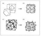
- FIG. 1 is a diagram showing an example of a three-dimensional structure generated from a plurality of polyhedra.
- FIG. 2 is a diagram showing an example of a crystal structure generated from a three-dimensional structure.
- FIG. 3 is a diagram showing another example of a crystal structure generated from a three-dimensional structure.
- FIG. 4 is a diagram showing an example of a crystal structure generated from a periodic graph.
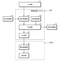
- FIG. 5 is a block diagram showing the overall configuration including the information processing system according to the first embodiment.
- FIG. 6 is a diagram showing an example of three-dimensional structure data stored in the first storage unit.
- FIG. 7 is a diagram illustrating an example of third information stored in the second storage unit.
- FIG. 8 is a diagram showing an image displayed on the display unit in the first usage example of the first embodiment.
- FIG. 1 is a diagram showing an example of a three-dimensional structure generated from a plurality of polyhedra.
- FIG. 2 is a diagram showing an example of a crystal structure generated from
- FIG. 9 is a diagram showing an image displayed on the display unit in the first usage example of the first embodiment.
- FIG. 10 is a diagram showing an image displayed on the display unit in the second usage example of the first embodiment.
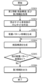
- FIG. 11 is a flowchart illustrating an example of the operation of the information processing system according to the first embodiment.
- FIG. 12 is a diagram illustrating an example of placement pattern candidates.
- FIG. 13 is a diagram showing an example of a crystal structure corresponding to an arrangement pattern candidate.
- FIG. 14 is a diagram showing another example of placement pattern candidates.
- FIG. 15 is a diagram showing another example of the crystal structure corresponding to the arrangement pattern candidate.
- FIG. 16 is a diagram illustrating an example of the arrangement of atoms in a candidate arrangement pattern.
- FIG. 17 is a sequence diagram illustrating an operation example of the information processing system, the display unit, the first storage unit, and the second storage unit according to the first embodiment.
- FIG. 18 is a diagram illustrating an example of an image displayed on the display unit according to the second embodiment.
- FIG. 19 is a flowchart illustrating an example of the operation of the information processing system according to the second embodiment.
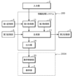
- FIG. 20 is a block diagram showing the overall configuration including the information processing system according to the third embodiment.
- FIG. 21 is a flowchart illustrating an example of the operation of the information processing system according to the third embodiment.
- FIG. 22 is a sequence diagram illustrating an operation example of the information processing system, the display unit, the first storage unit, and the second storage unit according to the third embodiment.
- FIG. 23 is a diagram illustrating an example of the second image displayed on the display unit according to the first usage example of the third embodiment.
- FIG. 24 is a diagram illustrating an example of the third image displayed on the display unit according to the first usage example of the third embodiment.
- FIG. 25 is a diagram showing an image displayed on the display unit in the second usage example of the third embodiment.
- FIG. 26 is a diagram showing another image displayed on the display unit in the second usage example of the third embodiment.
- FIG. 27 is a diagram showing still another image displayed on the display unit in the second usage example of the third embodiment.
- FIG. 28 is a diagram showing an image displayed on the display unit when selecting another physical property in the second usage example of the third embodiment.
- FIG. 29 is a flowchart showing another example of the operation of the information processing system according to the third embodiment.
- FIG. 30 is a diagram showing an image displayed on the display unit in a modified example.
- FIG. 31 is a diagram showing an image displayed on the display unit in a modified example.
- FIG. 32 is a diagram showing a specific example of converting a periodic graph into a three-dimensional structure.
- the physical properties of a material greatly depend on how atoms are coordinated with surrounding atoms, that is, on the local coordination environment of atoms. For example, in ionic crystalline materials, cations are surrounded by a group of anions. The polyhedron formed by connecting the centers of these anions is called a coordination polyhedron.
- AgI has a face-centered cubic lattice structure (fcc type structure) with low Ag ion conductivity and a body-centered cubic lattice structure (bcc type structure) with high Ag ion conductivity.
- I ions around Ag ions are formed by filling tetrahedral and octahedral coordination polyhedra. Since Ag ions are more stable at octahedral sites, they cannot move to adjacent tetrahedral sites, making it difficult for Ag ions to conduct. On the other hand, in the bcc type structure, the I ions around the Ag ions are formed by filling a tetrahedral coordination polyhedron, and all sites are equivalent, so the Ag ions are easily conductive.
- Patent Document 1 and Patent Document 2 disclose a method of generating a new structure based on a structural feature vector.
- Patent Document 1 and Patent Document 2 do not disclose a method for generating a new crystal structure based on coordination polyhedra.
- Non-Patent Document 1 discloses a method of generating a new crystal structure based on symmetry. However, Non-Patent Document 1 does not disclose a method for generating a new crystal structure based on coordination polyhedra.
- an information processing method is an information processing method executed by a computer, which includes a step of acquiring first information regarding a plurality of polyhedra; a step of obtaining second information regarding the plurality of atoms arranged in each of the plurality of atoms; and based on the first information and the second information, each of the plurality of atoms is arranged in the three-dimensional structure in which the plurality of polyhedra are arranged.
- the method includes the steps of generating third information indicating a possible crystal structure when arranged, and outputting the generated third information.
- the three-dimensional structure may be a structure in which the plurality of polyhedra are arranged without gaps.
- the step of acquiring the first information information regarding the three-dimensional structure in which the plurality of polyhedra are arranged without gaps may be acquired as the first information.
- the information regarding the three-dimensional structure is at least one of the following: information indicating the three-dimensional structure, information indicating a numerical sequence including numbers or letters representing the three-dimensional structure, and information indicating a periodic graph representing the three-dimensional structure. It may include one.
- a crystal structure having a space-filling structure in three-dimensional space can be generated using various methods.
- the third information indicating the crystal structure may be generated using possible arrangement patterns of the plurality of atoms in the crystal structure.
- the arrangement pattern may indicate that the atoms are arranged at at least one of the vertices of each of the plurality of polyhedra and the inside of each of the plurality of polyhedra.
- step of acquiring the second information material information regarding the material containing the atoms arranged in each of the plurality of polyhedra is acquired as the second information, and in the step of generating the third information, , the third information indicating the crystal structure that the material can have may be generated based on the material information.
- element information indicating the type of each of the plurality of atoms is further acquired as the material information
- the element information indicated by the element information is further acquired.
- the third information indicating the crystal structure in which one or more types of atoms are arranged may be generated.
- composition information regarding the composition of the material is further acquired as the material information
- the step of generating the third information the crystal structure having the composition indicated by the composition information is further acquired. You may generate the third information indicating.
- a crystal structure can be generated under the constraints of the composition specified by the user, for example, so it is easy to generate the crystal structure desired by the user.
- atomic number information indicating the number of the plurality of atoms arranged in each of the plurality of polyhedra is further acquired as the material information, and the third information is generated.
- the third information indicating the crystal structure in which the atoms are arranged as many as the number of atoms indicated by the atomic number information may be generated.
- the crystal structure information indicating a basic crystal structure that is the basis of the crystal structure is acquired
- the crystal structure information is The third information may be generated indicating the crystal structure that can be obtained when the atoms are arranged in the basic crystal structure indicated by the information.
- a crystal structure can be generated under the constraints of, for example, the basic crystal structure specified by the user, so it is easy to generate the crystal structure desired by the user.
- a crystal structure can be generated under the constraints of, for example, the basic crystal structure specified by the user, so it is easy to generate the crystal structure desired by the user.
- the method may further include the step of calculating and outputting fourth information regarding the physical properties of the crystal structure indicated by the third information using at least one of first-principles calculations and machine-learning predictive models.
- the third information may be output limited to the crystal structure having predetermined physical properties based on the calculated fourth information.
- a crystal structure can be generated under the constraints of, for example, the physical properties of the crystal structure specified by the user, so it is easy to generate the crystal structure desired by the user.
- the information processing system displays a first image that receives input of first information regarding a plurality of polyhedra and second information regarding a plurality of atoms arranged in each of the plurality of polyhedra.
- a display control section that causes the display section to display a second image representing third information indicating.
- the first image includes a first input image that accepts input of the first information, and a second input image that accepts input of the second information, and the display control unit is configured to input the second input image.
- the first input image may be displayed on the display section based on the input second information.
- a program includes the steps of: acquiring first information regarding a plurality of polyhedra; acquiring second information regarding a plurality of atoms arranged in each of the plurality of polyhedra; 1 information and the second information, generating third information indicating a possible crystal structure when each of the plurality of atoms is arranged in a three-dimensional structure in which the plurality of polyhedra are arranged; and outputting the third information obtained by the computer.
- the present invention can also be implemented as a computer program that causes a computer to execute the characteristic processing included in the information processing method of the present disclosure. It goes without saying that such a computer program can be distributed via a computer-readable non-transitory recording medium such as a CD-ROM or a communication network such as the Internet.
- the three-dimensional structure is a structure in a three-dimensional space, particularly a space-filling structure in a three-dimensional space, in other words, a structure in which a plurality of polyhedra are completely filled in the three-dimensional space without gaps.
- FIG. 1 is a diagram showing an example of a three-dimensional structure generated from a plurality of polyhedra.
- FIG. 1A shows a face-centered cubic lattice structure (FCC type structure) composed of a plurality of regular tetrahedra and a plurality of regular octahedrons.
- FIG. 1B shows a body-centered cubic lattice structure (bcc type structure) composed of a plurality of regular tetrahedra.
- FIG. 1C shows a hexagonal close-packed structure (hcp type structure) composed of a plurality of regular tetrahedra and a plurality of regular octahedrons.
- FIG. 1(d) shows a perovskite structure composed of one regular octahedron and multiple cuboctahedrons. Although one cuboctahedron is shown in FIG. 1(d), in reality, a plurality of cuboctahedrons are arranged without gaps around the regular octahedron at the center.
- FIG. 1(e) shows a MgCu type 2 structure composed of a plurality of regular tetrahedra.
- the structure of an inorganic material can be regarded as a three-dimensional structure
- the technology of the present disclosure that can generate a crystal structure by inputting information on multiple polyhedra, such as the three-dimensional structure, can be applied to unknown materials. It is very effective for searching.
- FIG. 2 is a diagram showing an example of a crystal structure generated from a three-dimensional structure.
- a three-dimensional structure that is an fcc type structure shown in FIG. NaCl having a rock salt type structure shown in 2(b) is obtained.
- a three-dimensional structure that is a bcc type structure shown in FIG. 2(c) if I is placed at the vertex site and Ag is placed at the center site of the tetrahedron, AgI shown in FIG. 2(d) The type structure of AgI is obtained.
- a three-dimensional structure that is an hcp type structure shown in FIG. When holes are arranged at the center site of the face piece, ZnO having a wurtzite structure shown in FIG. 2(f) is obtained.
- FIG. 3 is a diagram showing another example of a crystal structure generated from a three-dimensional structure.
- a three-dimensional structure that is a perovskite structure shown in FIG. SrTiO 3 having a perovskite structure shown in FIG. 3(b) is obtained.
- the three-dimensional structure of the MgCu type 2 structure shown in FIG. Li 6 PS 5 Cl having an argyrodite structure shown in d) is obtained.
- the technology of the present disclosure creates a three-dimensional structure, that is, an arrangement, by arranging elements or holes at the vertex sites and center sites of each polyhedron in a three-dimensional structure based on input information on a plurality of polyhedra. Crystal structures based on topological polyhedra can be generated. Therefore, with the technology of the present disclosure, it is possible to generate a crystal structure that matches an actual crystal structure, and it is easy to generate a crystal structure with high prediction accuracy.
- a molecular structure can be expressed as a graph. That is, the molecular structure can be expressed as a graph structure in which the "atoms" constituting a compound are “nodes” and the “bonds between atoms" are “edges” connecting the nodes.
- Patent Document 2 Japanese Unexamined Patent Publication No. 2021-081769
- a periodic graph is also called a crystal net, and is a three-dimensional periodic graph.
- "three-dimensionally periodic” means that three linearly independent translations exist.
- a crystal structure can be converted into a periodic graph by defining the bonds between atoms in the crystal structure.
- a periodic graph can be uniquely converted into a crystal structure.
- a periodic graph with two independent nodes and four edges connecting them, as shown in Figure 4(a) can be interconverted with the diamond-shaped structure shown in Figure 4(b). be.
- the periodic graph is a graph that can be converted into a crystal structure that can be obtained when each of a plurality of atoms is arranged in a three-dimensional structure in which a plurality of polyhedra are arranged.
- the information processing system may be configured such that all the components are included in one computer, or may be configured as a system in which multiple components are respectively distributed among multiple computers. It's okay.
- FIG. 5 is a block diagram showing the overall configuration including the information processing system 100 according to the first embodiment.
- the information processing system 100 is configured as a computer such as a personal computer or a server, for example. That is, the information processing system 100 may be realized by cloud computing, for example.
- Embodiment 1 will be described assuming that information processing system 100 is a stationary computer.
- the information processing system 100 includes a first acquisition unit 11, a second acquisition unit 12, a generation unit 13, and an output unit 14. Further, the information processing system 100 is connected to an input section 2, a display control section 30, a display section 3, a first storage section 4, and a second storage section 5.
- the input unit 2, the display control unit 30, and the display unit 3 are configured by an information terminal used by a user, such as a smartphone, a tablet terminal, or a personal computer.
- the input unit 2, display control unit 30, and display unit 3 may be an input unit, a display control unit, and a display unit included in an information terminal used by a user.
- the input unit 2, the display control unit 30, the first storage unit 4, and the second storage unit 5 may all be connected to the information processing system 100 via a LAN (Local Area Network) or the like, or may be connected to the information processing system 100 via a LAN (Local Area Network) or the like. It may be connected to the information processing system 100 via a network.
- LAN Local Area Network
- the input unit 2, the display control unit 30, the first storage unit 4, and the second storage unit 5 may all be connected to the information processing system 100 via a LAN (Local Area Network) or the like, or may be connected to the information processing system 100 via a LAN (Local Area Network) or the like. It may be connected to the information processing system 100 via a network.
- the input unit 2 is an input interface that accepts user input, and is composed of, for example, a keyboard, a touch sensor, a touch pad, a mouse, or the like.
- the input unit 2 receives an input operation by a user, and outputs a signal corresponding to the input operation to the information processing system 100.
- the display section 3 and the input section 2 are configured independently from each other, but they may be configured integrally like a touch panel.
- the information processing system 100 does not include the display unit 3 and the input unit 2, but may include these.
- the input unit 2 receives input of first information regarding a plurality of polyhedra and input of second information regarding a plurality of atoms arranged in each of the plurality of polyhedra.
- the first information is, for example, a three-dimensional structure.
- the first information may be, for example, the type of polyhedron, the number of polyhedra, the permissible skewness, or the permissible symmetry.
- the first information has a three-dimensional structure.
- the second information may include, for example, the type of element placed at the center site and apex site of each polyhedron, the composition ratio of the elements placed at the center site and apex site of each polyhedron, or symmetry.
- a plurality of atoms includes a case where there is a plurality of one type of element, and also includes a case where there is a plurality of atoms as the total number of two or more types of elements. Note that the composition ratio and symmetry of elements are not essential information.
- the display control unit 30 causes the display unit 3 to display images and the like based on information output from the output unit 14 of the information processing system 100.
- the display unit 3 displays images and the like under the control of the display control unit 30.
- the display unit 3 is, for example, a liquid crystal display, a plasma display, an organic EL (Electro-Luminescence) display, or the like, but is not limited thereto.
- the first storage unit 4 is a recording medium for storing a three-dimensional structure database.
- the recording medium is, for example, a hard disk drive, RAM (Random Access Memory), ROM (Read Only Memory), or semiconductor memory. Note that such a recording medium may be volatile or nonvolatile.
- the three-dimensional structure database includes data regarding three-dimensional structures. Examples of three-dimensional structures recorded in the three-dimensional structure database include fcc-type structures, bcc-type structures, hcp-type structures, perovskite-type structures, and MgCu 2 -type structures.
- the three-dimensional structure data is used when the user inputs first information through the input unit 2.
- FIG. 6 is a diagram showing an example of three-dimensional structure data stored in the first storage unit 4.
- 6(a) shows a three-dimensional structure (in this case, an FCC type structure), and
- FIG. 6(b) shows the three-dimensional structure shown in FIG. 6(a) in a predetermined description format ( Here, data written in D-Symbol format is shown.
- the first storage unit 4 stores, for example, an image showing a three-dimensional structure as shown in FIG. 6(a), and data described in a predetermined description format as shown in FIG. 6(b). Saved as structural data.
- the second storage unit 5 is a recording medium for storing third information indicating the crystal structure generated by the generation unit 13.
- the recording medium is, for example, a hard disk drive, RAM (Random Access Memory), ROM (Read Only Memory), or semiconductor memory. Note that such a recording medium may be volatile or nonvolatile.
- FIG. 7 is a diagram showing an example of the third information stored in the second storage unit 5.
- (a) of FIG. 7 shows the crystal structure shown by the third information (here, the structure of NaCl), and
- (b) of FIG. 7 shows the crystal structure shown in (a) of FIG. It shows data written in a format (here, cif format).
- the second storage unit 5 stores, for example, an image showing a crystal structure as shown in FIG. 7(a) and data described in a predetermined description format as shown in FIG. Saved as .
- the third information includes, for example, an image, three-dimensional data, graph data, space group, Wyckoff label, cell size, lattice constant, angle, composition, element type, or atomic coordinates.
- the file format (extension) of the data saved in the second storage unit 5 is, for example, *. cif, *. pdb, *. ins,*. xyz, *. cc1, *. stl, *. wrl, *. pme, *. stin, *. p1, *. vasp, or *. xtl etc.
- the first acquisition unit 11 acquires first information regarding a plurality of polyhedra.
- the first acquisition unit 11 is the main entity that executes the step of acquiring first information in the information processing method of the present disclosure. Specifically, the first acquisition unit 11 acquires the first information input by the user through the input unit 2. As will be described later, the user performs an operation to input the first information while viewing the first image displayed on the display unit 3 and accepting input of the first information and the second information.
- the second acquisition unit 12 acquires second information regarding atoms arranged in each of the plurality of polyhedra.
- the second acquisition unit 12 is the main body that executes the step of acquiring second information in the information processing method of the present disclosure. Specifically, the second acquisition unit 12 acquires the second information input by the user through the input unit 2. As will be described later, the user performs an operation to input the second information while viewing the first image displayed on the display unit 3 and accepting input of the first information and the second information.
- the generation unit 13 generates each of the plurality of atoms in a three-dimensional structure in which the plurality of polyhedra are arranged, based on the first information acquired by the first acquisition unit 11 and the second information acquired by the second acquisition unit 12. Third information indicating the crystal structure that can be obtained when the crystal structure is arranged is generated.
- the generation unit 13 is the main body that executes the step of generating the third information in the information processing method of the present disclosure. In the first embodiment, the generation unit 13 executes a process of generating third information indicating the crystal structure using each possible arrangement pattern of a plurality of atoms in the crystal structure.
- the arrangement pattern indicates that atoms are arranged at at least one of the vertices of each of the plurality of polyhedra and the interior (center) of each of the plurality of polyhedra.
- the arrangement pattern of Embodiment 1 is obtained by a combination of the positions of each of a plurality of atoms that can be taken in the crystal structure. Details of the above processing will be described later.
- the output unit 14 causes the display unit 3 to display the image etc. by outputting the image etc. to the display control unit 30. Furthermore, the output unit 14 outputs the third information generated by the generation unit 13.
- the output unit 14 is the main body that executes the step of outputting the third information in the information processing method of the present disclosure. Specifically, the output unit 14 outputs the second information by displaying the second image representing the third information generated by the generation unit 13 on the display unit 3. As will be described later, the user performs an operation to select third information to be stored in the second storage unit 5 while viewing the second image displayed on the display unit 3.
- FIG. 8 and 9 are diagrams showing images displayed on the display unit 3 in the first usage example of the first embodiment.
- (a) of FIG. 8 represents an example of the first image displayed on the display unit 3.
- the first image is displayed on the display unit 3 by the output unit 14 by reading the three-dimensional structure data stored in the first storage unit 4.
- the first image includes a three-dimensional structure selection area for selecting a three-dimensional structure, a placement specification area for selecting the arrangement of atoms, and an execution icon called "Generate". There is.
- the three-dimensional structure selection area a plurality of three-dimensional structures that can be selected by the user and a plurality of selection buttons that respectively correspond to the plurality of three-dimensional structures are displayed.
- the name of each three-dimensional structure may be displayed in the three-dimensional structure selection area.
- each three-dimensional structure may be displayed as a moving image instead of a still image.
- the user selects a three-dimensional structure in the three-dimensional structure selection area.
- the first acquisition unit 11 acquires, as the first information, information regarding a three-dimensional structure in which a plurality of polyhedra are arranged without gaps.
- the generation unit 13 when the user selects the execution icon, the generation unit 13 (in the step of generating third information) generates third information indicating a crystal structure based on the selected three-dimensional structure.
- the generation unit 13 generates third information indicating the crystal structure based on the fcc type structure.
- the user has data regarding a three-dimensional structure that does not appear in the options in the three-dimensional structure selection area, it is also possible to input the three-dimensional structure.
- the 3D structure owned by the user is transferred to the first acquisition unit 11. can be obtained.
- the placement specification area displays a text box for specifying the element (atom) placed at the vertex of each polyhedron, and a text box for specifying the element (atom) placed at the center of each polyhedron. has been done.
- the user enters the desired element in each text box. Note that, for example, if the user wants to place a hole at the center of each polyhedron, the user may leave the corresponding text box blank.
- the second acquisition unit 12 obtains, as the second information, material information about the material having atoms arranged in each of the plurality of polyhedra, and more specifically, the material information about the material having atoms arranged in each of the plurality of polyhedra.
- Elemental information indicating the type of atom placed in each element will be acquired.
- the generation unit 13 in the step of generating the third information
- the generation unit 13 generates the crystal structure that the material can have based on the material information, and more specifically, the type of atoms indicated by the elemental information. generates third information indicating the crystal structure in which is arranged.
- the user inputs "Se” as the element to be placed at the vertex of the polyhedron, and "Cu” and “In” as the elements to be placed at the center of the polyhedron.
- the user may select "Se,” “Cu,” or “In” from the periodic table or preset candidate element options. Therefore, in this case, the generation unit 13 generates third information indicating a crystal structure in which “Se” is placed at the apex of the polyhedron and “Cu” or “In” is placed at the center of the polyhedron.
- FIG. 8(b) shows an example of the second image displayed on the display unit 3.
- the second image is displayed on the display unit 3 after the user selects the execution icon in the first image and the generation unit 13 generates third information indicating the crystal structure.
- the second image includes a table showing a list of crystal structures generated by the generation unit 13 and an execution icon that says "Export selected crystal structure.” In this table, from the left, a column for selecting the crystal structure to be exported, a column for displaying the identification number (ID) for each crystal structure, a column for displaying the composition of the crystal structure, and a column for displaying the symmetry of the crystal structure (here, , space group), and a column indicating the number of atoms included in the unit cell of the crystal structure.
- ID identification number
- FIGS. 9(a) to (c). show an image including an area showing the selected crystal structure and an execution icon "Save image” on the display unit 3, as shown in FIGS. 9(a) to (c). .
- FIG. 9(a) shows the image when the crystal structure with the identification number "1" is selected
- FIG. 9(b) shows the image when the crystal structure with the identification number "2" is selected
- FIG. 9C shows an image when the crystal structure with the identification number "3" is selected.
- the display unit 3 displays an image including a selection area for selecting the storage format of the crystal structure and an execution icon "save". Note that in the example shown in FIG. 9(d), the user can select either ".cif” or ".vasp", but even if it is possible to select other storage formats, good.
- third information indicating the crystal structure selected by the user is stored in the second storage unit 5.
- FIG. 10 is a diagram showing an image displayed on the display unit 3 in the second usage example of the first embodiment.
- (a) of FIG. 10 represents an example of the first image displayed on the display unit 3.
- FIG. 10(b) represents an example of the second image displayed on the display unit 3.
- the first image differs from the first usage example in that it includes a composition specification area for the user to specify a desired composition, and the maximum number of atoms in a unit cell in the crystal structure. It further includes a maximum number of atoms specification area for specifying .
- a text box for specifying the composition of the crystal structure is displayed.
- the user enters the desired composition in the text box.
- the second acquisition unit 12 in the step of acquiring the second information
- the generation unit 13 in the step of generating third information
- the generation unit 13 generates third information indicating a crystal structure having the composition indicated by the composition information.
- the user specifies "CuInSe 2 " as the composition of the crystal structure. Therefore, in this case, the generation unit 13 generates third information indicating a crystal structure having the composition "CuInSe 2 ". Therefore, in the second image, as shown in FIG. 10(b), a crystal structure having the composition "CuInSe 2 " is displayed.
- a text box for specifying the maximum number of atoms in the unit cell of the crystal structure is displayed in the maximum number of atoms specification area.
- the user enters the desired number in the text box.
- the second acquisition unit 12 (in the step of acquiring the second information) obtains, as material information, the number of atoms arranged in each of the plurality of polyhedra (here, the maximum number of atoms in the unit cell). Further, atomic number information indicating .
- the generation unit 13 (in the step of generating the third information) arranges atoms as many as the number of atoms indicated by the atomic number information (here, the atoms specified in the unit cell are third information indicating a crystal structure (in which atoms are arranged so as not to exceed the maximum value of the number) is generated.
- the generation unit 13 generates third information indicating a crystal structure in which the number of atoms in the unit cell is "16" or less. Therefore, in the second image, as shown in FIG. 10(b), a crystal structure in which the number of atoms in the unit cell is "16" or less is displayed.
- the first image includes both the composition specification area and the maximum atomic number specification area, but may include either one of them.
- FIG. 11 is a flowchart illustrating an example of the operation of the information processing system 100 according to the first embodiment.
- the first acquisition unit 11 acquires first information.
- the first information is input by the user using the input unit 2 while reading the three-dimensional structure data stored in the first storage unit 4 and viewing the first image displayed on the display unit 3.
- the first acquisition unit 11 acquires the information.
- the first information may be acquired by the first acquisition unit 11 by the user inputting original data using the input unit 2 without referring to the first image.
- the second acquisition unit 12 acquires second information. As described above, the second information is acquired by the second acquisition unit 12 by the user inputting (selecting) using the input unit 2 while viewing the first image displayed on the display unit 3 .
- the generation unit 13 executes a process of generating placement pattern candidates based on the acquired first information and second information.
- the generation unit 13 generates placement pattern candidates for each of a pattern in which atoms are placed at the vertex site of each polyhedron and a pattern in which atoms are placed at the center site of each polyhedron.
- atoms may be arranged randomly or atoms may be arranged efficiently based on a predetermined rule.
- a predetermined law for example, P. V. Bushlanov, V. A. Blatov and A. R.
- they are arranged so as to satisfy the symmetry of the space group.
- the generation unit 13 executes a process of generating a crystal structure for each arrangement pattern candidate. Specifically, the generation unit 13 generates a crystal structure by arranging atoms at the vertices of each polyhedron and at the center of each polyhedron according to the content of the arrangement pattern candidate.
- Step S104 The generation unit 13 determines whether there are any other placement pattern candidates for which no crystal structure has been generated. If it is determined that there are other placement pattern candidates (step S104: Yes), the generation unit 13 returns to step S103. When crystal structures have been generated for all arrangement pattern candidates (step S104: No), the processing of the generation unit 13 is completed. The information processing system 100 (information processing method) then executes step S105.
- Step S105 The output unit 14 executes a process of outputting the third information generated by the generation unit 13.
- the output unit 14 outputs the third information by displaying the second image representing the third information generated by the generation unit 13 on the display unit 3.
- the display section 3 may include a display control section 30.
- the display section 3 including the display control section 30 may be referred to as a display section 3A.
- the output unit 14 may output the third information generated by the generation unit 13 to the display unit 3A. Thereby, the display unit 3A may display the second image representing the third information. That is, the output unit 14 may display the second image representing the third information on the display unit 3A.
- FIG. 12 is a diagram illustrating an example of placement pattern candidates.
- FIG. 13 is a diagram showing an example of a crystal structure corresponding to an arrangement pattern candidate.
- FIG. 14 is a diagram showing another example of placement pattern candidates.
- FIG. 15 is a diagram showing another example of the crystal structure corresponding to the arrangement pattern candidate.
- FIG. 16 is a diagram illustrating an example of the arrangement of atoms in a candidate arrangement pattern.
- FIG. 12 shows a table showing a list of arrangement pattern candidates for an FCC type structure of a unit cell.
- the "vertex site” column in FIG. 12 indicates the elements (atoms) arranged at the vertices of each polyhedron.
- “A”, “B”, “C”, and “D” in the “Vertex Site” column correspond to “X1”, “X2”, “X3”, and “X4” in the atomic arrangement shown in FIG. 16, respectively.
- the "tetrahedral center site” column in FIG. 12 indicates an element (atom) or a hole located at the center of the tetrahedron.
- “A”, “B”, “C”, “D”, “E”, “F”, “G”, and “H” in the “tetrahedral center site” column are respectively in the atomic arrangement shown in FIG. It corresponds to “T1”, “T2”, “T3”, “T4", “T5", “T6”, “T7”, and “T8".
- the "octahedron center site” column in FIG. 12 indicates the element (atom) or hole located at the center of the octahedron.
- “A”, “B”, “C”, and “D” in the “octahedral center site” column correspond to “O1”, “O2”, “O3”, and “O4” in the atomic arrangement shown in Figure 16, respectively. handle.
- the “composition” column in FIG. 12 indicates the composition of the crystal structure.
- FIG. 13 shows a crystal structure corresponding to "arrangement pattern candidate 1" in FIG. 12. That is, in (a) of FIG. 13, the composition is "CuInSe 2 ", “Se” is placed at the vertex of each polyhedron, “Cu”, “In”, or a hole is placed at the center of each tetrahedron, and each 8 It shows a crystal structure in which a hole is placed in the center of a hedron.
- FIG. 13(b) shows a crystal structure corresponding to "arrangement pattern candidate 4" in FIG. 12. That is, in FIG.
- the composition is "CuInSe", with “Se” at the apex of each polyhedron, “Cu” or “In” at the center of each tetrahedron, and an empty space at the center of each octahedron.
- FIG. 13(c) shows a crystal structure corresponding to "arrangement pattern candidate 8" in FIG. 12. That is, in FIG. 13(c), the composition is "CuInSe --2 ", with “Se” at the apex of each polyhedron, a hole at the center of each tetrahedron, and "Cu” at the center of each octahedron. Or, it shows a crystal structure in which "In” is arranged.
- FIG. 14 shows a table showing a list of layout pattern candidates for a 1 ⁇ 1 ⁇ 2 supercell fcc type structure.
- the "vertex site” column and the “octahedral center site” column are omitted, and a part of the “tetrahedral center site” column is omitted.
- FIG. 15 shows a crystal structure corresponding to "arrangement pattern candidate 1" in FIG. 14. That is, in FIG. 15, the composition is "CuInSe 2 ", with “Se” at the apex of each polyhedron, "Cu", "In”, or a hole at the center of each tetrahedron, and a hole at the center of each octahedron. Shows a crystal structure with holes arranged.
- FIG. 17 is a sequence diagram showing an example of the operation of the information processing system 100, the display section 3, the first storage section 4, and the second storage section 5 according to the first embodiment.
- the first acquisition unit 11 of the information processing system 100 acquires first information.
- the first information is input (selected) by the user using the input unit 2 while reading the three-dimensional structure data stored in the first storage unit 4 and viewing the first image displayed on the display unit 3.
- the data is acquired by the first acquisition unit 11.
- the second acquisition unit 12 of the information processing system 100 acquires second information.
- the second information is acquired by the second acquisition unit 12 by the user inputting (selecting) using the input unit 2 while viewing the first image displayed on the display unit 3 .
- Step S202 The generation unit 13 executes a process of generating placement pattern candidates based on the acquired first information and second information.
- Step S203 The generation unit 13 executes a process of generating a crystal structure for each arrangement pattern candidate.
- the display unit 3 displays a second image representing third information output from the output unit 14 of the information processing system 100.
- the display section 3 may include a display control section 30.
- the display section 3 including the display control section 30 may be referred to as a display section 3A.
- the output unit 14 may cause the display unit 3A to display a second image representing the third information.
- Step S205 When the user selects a crystal structure to save while viewing the second image displayed on the display unit 3, the information processing system 100 provides the second storage unit 5 with third information indicating the selected crystal structure. Thereby, the second storage unit 5 stores the third information indicating the crystal structure selected by the user.
- the first embodiment information on a plurality of polyhedra is input, and in a three-dimensional structure based on the input information on the plurality of polyhedra, elements or holes are placed at the vertex sites and center sites of each polyhedron.
- a three-dimensional structure that is, a crystal structure based on a coordination polyhedron. Therefore, in the first embodiment, it is possible to generate a crystal structure that matches the actual crystal structure, and it is easy to generate a crystal structure with high prediction accuracy.
- the information processing system according to the second embodiment is different from the information processing system according to the first embodiment in that the first acquisition unit 11 acquires crystal structure information indicating a basic crystal structure that is the basis of the crystal structure as the first information. It is different from 100. Further, the information processing system according to the second embodiment is similar to the second embodiment in that the generation unit 13 generates third information indicating a possible crystal structure when atoms are arranged in the basic crystal structure indicated by the crystal structure information.
- the information processing system 100 according to No. 1 is different from the information processing system 100 according to No. 1.
- the information processing system according to the second embodiment like the information processing system 100 according to the first embodiment, includes a first acquisition section 11, a second acquisition section 12, a generation section 13, and an output section 14. , and the configuration is common, so a description of these will be omitted.
- FIG. 18 is a diagram showing an example of an image displayed on the display unit 3 according to the second embodiment.
- FIG. 18 shows an example of the first image displayed on the display unit 3.
- the first image is a crystal structure for selecting a basic crystal structure that is the basis of the crystal structure generated by the generation unit 13, instead of a three-dimensional structure selection area. Contains a selection area.
- the crystal structure selection area a plurality of basic crystal structures that can be selected by the user and a plurality of selection buttons respectively corresponding to the plurality of basic crystal structures are displayed.
- the name of each basic crystal structure may be displayed in the crystal structure selection area.
- each basic crystal structure may be displayed as a moving image instead of a still image.
- the user selects a basic crystal structure in the crystal structure selection area.
- the first acquisition unit 11 acquires, as the first information, crystal structure information indicating a basic crystal structure that is the basis of the crystal structure.
- the generation unit 13 in the step of generating third information
- the generation unit 13 generates third information indicating a crystal structure based on the selected basic crystal structure.
- the user can cause the first acquisition unit 11 to acquire the basic crystal structure owned by the user. .
- FIG. 19 is a flowchart illustrating an example of the operation of the information processing system according to the second embodiment.
- the first acquisition unit 11 acquires first information.
- the first information is crystal structure information as described above, and is input (selected) by the user using the input unit 2 while viewing the first image displayed on the display unit 3. Then, it is acquired by the first acquisition unit 11.
- the second acquisition unit 12 acquires second information. The second information is the same as in the first embodiment.
- Step S302 The generation unit 13 determines the vertex site of each polyhedron and the center site of each polyhedron in the basic crystal structure based on the acquired first information. In other words, the generation unit 13 (in the step of generating the third information) determines the positions of the vertices of each of the plurality of polyhedra in which atoms are arranged, and the positions of the vertices of the plurality of polyhedra, based on the basic crystal structure indicated by the crystal structure information. Determine the internal (center) position of each.
- Step S303 Similar to the first embodiment, the generation unit 13 executes a process of generating placement pattern candidates based on the acquired first information and second information.
- Step S304 Similar to the first embodiment, the generation unit 13 executes a process of generating a crystal structure for each arrangement pattern candidate.
- Step S305 Similar to the first embodiment, the generation unit 13 determines whether there are any other placement pattern candidates for which no crystal structure has been generated. If it is determined that there are other placement pattern candidates (step S305: Yes), the generation unit 13 returns to step S304. When crystal structures have been generated for all arrangement pattern candidates (step S305: No), the processing of the generation unit 13 is completed. The information processing system (information processing method) then executes step S306.
- Step S306 The output unit 14 executes the process of outputting the third information generated by the generation unit 13, as in the first embodiment.
- a crystal structure can be generated by inputting information on a basic crystal structure that is the basis of the crystal structure to be generated. Therefore, in the second embodiment, as in the first embodiment, it is possible to generate a crystal structure that conforms to the actual crystal structure, and it is easy to generate a crystal structure with high prediction accuracy.
- Embodiment 3 an information processing system 200 (information processing method or program) according to Embodiment 3 of the present disclosure will be described in detail using the drawings.
- the information processing system 200 according to the third embodiment differs from the information processing system 100 according to the first embodiment in that the generation unit 13 calculates and outputs fourth information regarding the physical properties of the crystal structure generated.
- FIG. 20 is a block diagram showing the overall configuration including an information processing system 200 according to the third embodiment.
- a third storage unit 6 is further connected to the information processing system 200 according to the second embodiment.
- the generation unit 13 has a function of calculating fourth information regarding the physical properties of the generated crystal structure. Note that a description of the configuration common to the information processing system 100 according to the first embodiment will be omitted.
- the third storage unit 6 is a recording medium for storing a compound database regarding physical property values (including predicted values) of existing materials.
- the recording medium is, for example, a hard disk drive, RAM (Random Access Memory), ROM (Read Only Memory), or semiconductor memory. Note that such a recording medium may be volatile or nonvolatile.
- the generation unit 13 predicts the physical properties of the crystal structure based on the generated crystal structure and the compound data read from the third storage unit 6.
- physical properties include indicators of synthesis possibility such as thermodynamic convex hull energy, optical properties such as band gap, electronic properties such as carrier mobility, dielectric properties such as relative permittivity, and ion conduction. It may include transport physical properties such as power, electrochemical properties such as potential window, etc.
- the physical properties include information regarding the synthesis of the crystal structure. Information regarding synthesis may include candidates for raw materials used in synthesizing the crystal structure, conditions for synthesis, and the like.
- the physical properties of the crystal structure can be calculated using, for example, first-principles calculations or machine-learned predictive models.
- the thermodynamic convex hull energy or bandgap of a crystal structure can be calculated using first principles calculations.
- the thermodynamic convex hull energy or band gap of a crystal structure can be calculated (estimated) using a prediction model.
- the prediction model is constructed by a graph neural network that receives the graph structure as input.
- the graph neural network is, for example, CGCNN (Crystal Graph Convolutional Neural Network) or MEGNet (Material Graph Network).
- the prediction model is configured by MEGNet.
- MEGNet is a graph neural network that uses not only nodes (nodes/vertices) and edges (branches/sides) as feature quantities, but also global state quantities representing the characteristics of the entire target system as feature quantities.
- the prediction model is machine-trained to output the total energy of an arbitrary crystal structure in response to an input crystal structure.
- the learning data set includes a crystal structure as input data and total energy corresponding to the crystal structure as correct data.
- FIG. 21 is a flowchart illustrating an example of the operation of the information processing system 200 according to the third embodiment.
- the first acquisition unit 11 acquires first information.
- the first information is obtained by reading the three-dimensional structure data stored in the first storage unit 4 and viewing the first image displayed on the display unit 3, as in the first embodiment.
- the first acquisition unit 11 acquires the information.
- the second acquisition unit 12 acquires second information. The second information is the same as in the first embodiment.
- Step S402 Similar to the first embodiment, the generation unit 13 executes a process of generating placement pattern candidates based on the acquired first information and second information.
- Step S403 Similar to the first embodiment, the generation unit 13 executes a process of generating a crystal structure for each arrangement pattern candidate. Here, in step S403, the generation unit 13 generates crystal structures for all arrangement pattern candidates.
- Step S404 The generation unit 13 executes a process of predicting the physical properties of the crystal structure based on the generated crystal structure and the compound data read from the third storage unit 6. For example, the generation unit 13 calculates thermodynamic convex hull energy as a physical property of the crystal structure. For example, when the composition of the crystal structure is "CuInSe 2 ", the thermodynamic convex hull energy is expressed by the following formula.
- thermodynamic convex hull energy indicates the thermodynamic convex hull energy of the crystal structure "A”
- Etot(A) indicates the total energy of the crystal structure "A”.
- the total energy of a crystal structure can be calculated using first-principles calculations or a machine-learned prediction model.
- thermodynamic convex hull energy can be expressed, for example, in a paper by Wenhao et al. y.” Science advances 2.11 (2016): e1600225.) It has been suggested that synthesis is possible as long as the voltage is 0.1 eV or less.
- the thermodynamic convex hull energy is an index of the synthesis possibility of a crystal structure.
- Step S405 The output unit 14 executes a process of outputting the fourth information generated by the generation unit 13.
- the output unit 14 outputs the fourth information by displaying the third image representing the fourth information generated by the generation unit 13 on the display unit 3.
- FIG. 22 is a sequence diagram showing an example of the operation of the information processing system 200, the display unit 3, the first storage unit 4, and the second storage unit 5 according to the third embodiment.
- Step S501 The first acquisition unit 11 of the information processing system 200 acquires first information.
- the first information is input (selected) by the user using the input unit 2 while reading the three-dimensional structure data stored in the first storage unit 4 and viewing the first image displayed on the display unit 3.
- the data is acquired by the first acquisition unit 11.
- the second acquisition unit 12 of the information processing system 200 acquires second information.
- the second information is acquired by the second acquisition unit 12 by the user inputting (selecting) using the input unit 2 while viewing the first image displayed on the display unit 3 .
- Step S502 The generation unit 13 of the information processing system 200 executes a process of generating a crystal structure for each arrangement pattern candidate. Note that between step S501 and step S502, the same processing as step S202 (see FIG. 17) is executed.
- the display unit 3 displays a second image representing third information output from the output unit 14 of the information processing system 200.
- the display section 3 may include a display control section 30.
- the display section 3 including the display control section 30 may be referred to as a display section 3A.
- the output unit 14 may cause the display unit 3A to display a second image representing the third information.
- Step S504 The first acquisition unit 11 (or second acquisition unit 12) of the information processing system 200 reads compound data stored in the third storage unit 6 and acquires the compound data.
- Step S505 The generation unit 13 of the information processing system 200 predicts the physical properties of the crystal structure based on the generated crystal structure and the compound data read from the third storage unit 6.
- Step S506 The display unit 3 displays a third image representing fourth information output from the output unit 14 of the information processing system 200.
- the output unit 14 may cause the display unit 3A to display a third image representing the fourth information.
- Step S507 When the user selects a crystal structure to be saved while viewing the third image displayed on the display unit 3, the information processing system 200 displays third information indicating the selected crystal structure and third information corresponding to the selected crystal structure. 4 information to the second storage unit 5. Thereby, the second storage unit 5 stores third information indicating the crystal structure selected by the user and fourth information corresponding to the selected crystal structure.
- FIG. 23 is a diagram showing an example of the second image displayed on the display unit 3 in the first usage example of the third embodiment.
- the second image is displayed on the display unit 3 after the user selects the execution icon in the first image and the generation unit 13 generates third information indicating the crystal structure.
- the second image includes a table showing a list of crystal structures generated by the generation unit 13 and an execution icon "Export selected crystal structure".
- the second image further includes a physical property selection area for selecting the physical property of the crystal structure to be predicted, and a prediction execution icon labeled "Predict physical property.”
- the physical property selection area physical properties of the crystal structure that can be selected by the user are displayed.
- the user can select one of "convex hull energy" and "bandgap," but other than crystal structure
- the physical properties may be selectable.
- the user wants to predict the physical properties of a crystal structure, he selects the physical properties of the crystal structure that he wants to predict in the physical property selection area, and selects the prediction execution icon. Thereby, the generation unit 13 executes a process of predicting the physical properties of the crystal structure.
- the user thinks that it is not necessary to predict the physical properties of the crystal structure, he selects the crystal structure he wants to save and selects the execution icon. In this case, the user can confirm the selected crystal structure and then save it in the second storage unit 5 without obtaining the prediction result of the physical properties of the crystal structure.
- FIG. 24 is a diagram showing an example of the third image displayed on the display unit 3 according to the first usage example of the third embodiment.
- the third image is displayed on the display unit 3 after the user selects the prediction execution icon in the second image and the generation unit 13 generates fourth information regarding the physical properties of the crystal structure.
- the third image includes a table showing a list of the crystal structures generated by the generation unit 13 and physical properties of the crystal structures predicted by the generation unit 13, and an execution icon “Export selected crystal structure”.
- the third image shown in FIG. 24(a) shows an image when the user selects "convex hull energy" in the physical property selection area.
- a "synthesizability index” column is included in the table, and this column indicates the thermodynamic convex hull energy of the crystal structure. Note that the smaller the thermodynamic convex hull energy of the crystal structure, the higher the possibility of synthesis.
- the third image shown in FIG. 24(b) shows an image when the user selects "bandgap" in the physical property selection area.
- the table includes a "Bandgap" column, which indicates the bandgap of the crystal structure.
- the user selects the crystal structure that he or she wants to save and selects the execution icon. Thereby, after confirming the selected crystal structure, the user can save the third information indicating the selected crystal structure and the fourth information regarding the physical properties of the selected crystal structure in the second storage unit 5. .
- FIG. 25 is a diagram showing an image displayed on the display unit 3 in the second usage example of the third embodiment.
- FIG. 25A shows a part of the first image that is displayed next on the display unit 3 when the user selects the physical property of the crystal structure in the physical property selection area in the first image.
- the user has selected "convex hull energy" as the physical property of the crystal structure.
- an execution icon "Please select threshold and condition", a text box for specifying the threshold, and a pull-down menu for specifying the condition are displayed.
- the generation unit 13 narrows down the generated crystal structures to those having a thermodynamic convex hull energy of 100 meV/atm or less and makes a prediction. That is, the generation unit 13 (in the step of generating the third information) determines a predetermined physical property (here, thermodynamic convex hull energy) based on the calculated fourth information (here, thermodynamic convex hull energy). 100 meV/atm or less) to generate the third information.
- a predetermined physical property here, thermodynamic convex hull energy
- FIG. 25(b) is a diagram showing an example of the third image displayed on the display unit 3.
- the third image further includes a "raw material candidate" column indicating raw material candidates for generating the crystal structure in the table.
- the raw material candidates shown in the "Raw Material Candidate" column merely indicate raw materials that have the possibility of generating a crystal structure, and it does not necessarily mean that a corresponding crystal structure can be generated if the raw materials are synthesized.
- FIG. 25(c) is a diagram showing an example of the third image displayed on the display section 3.
- the image shown in FIG. 25(c) may be displayed on the display unit 3 at the same time as the image shown in FIG. 25(b), or may be displayed on the display unit 3 separately from the image shown in FIG. 25(b). may be done.
- the third image shown in FIG. 25(c) includes a mapping area.
- the mapping area shows the mapping results showing the number of crystal structures that meet the specified threshold and conditions, the multiple elements (atoms) that make up the crystal structure are represented at the vertices, and the multiple compounds made of these multiple elements are represented on the line. A map and will be displayed.
- compositions of the crystal structure and the composition representing a phase thermodynamically coexisting with the crystal structure are displayed. Furthermore, in the map, compositions that have zero thermodynamic convex hull energy, that is, thermodynamically stable phases, are connected by straight lines.
- the crystal structure having the composition "CuInSe 2 " is located on the line. Therefore, the user can understand that the possibility of synthesizing the crystal structure is relatively high.
- the crystal structure having the composition "CuInSe” is not located on the line. Therefore, the user can understand that the possibility of synthesizing the crystal structure is relatively low.
- FIG. 26 is a diagram showing another image displayed on the display unit 3 in the second usage example of the third embodiment.
- the image shown in FIG. 26 is displayed on the display unit 3 when the user selects the composition of the crystal structure on the map in the image shown in FIG. (here, thermodynamic convex hull energy).
- the example shown in FIG. 26 shows an image when the user selects the crystal structure composition "CuInSe" on the map.
- FIG. 27 is a diagram showing still another image displayed on the display section 3 in the second usage example of the third embodiment.
- the image shown in Figure 27(a) is similar to the image shown in Figure 25(a), with an execution icon that says ⁇ Please select a threshold and conditions'', a text box for specifying a threshold, and a text box for specifying conditions. Includes a pull-down menu for specifying.
- the user inputs "50" into the text box and selects "less than” from the pull-down menu.
- the generation unit 13 narrows down the generated crystal structures to those having a thermodynamic convex hull energy of 50 meV/atm or less and makes a prediction.
- the image shown in FIG. 27(b) is similar to the image shown in FIG. 25(b), and shows the processing result by the generation unit 13 under the threshold and conditions shown in FIG. 27(a).
- the image shown in FIG. 27(c) is similar to the image shown in FIG. 25(c), and shows the processing result by the generation unit 13 under the threshold value and conditions shown in FIG. 27(a).
- FIG. 28 is a diagram showing an image displayed on the display unit 3 when selecting another physical property in the second usage example of the third embodiment.
- the user selects "bandgap" as the physical property of the crystal structure, enters "2.0" in the text box, and selects "less than” in the pull-down menu. ing.
- the generation unit 13 narrows down the generated crystal structures to those with a band gap of 2.0 eV or less and makes a prediction.
- FIG. 28(b) is an image similar to the image shown in FIG. 25(b), and shows the processing result by the generation unit 13 under the threshold value and conditions shown in FIG. 28(a).
- the third image includes a "bandgap" column instead of a "convex hull energy” column.
- FIG. 28(c) is an image similar to the image shown in FIG. 25(c), and shows the processing result by the generation unit 13 under the threshold value and conditions shown in FIG. 28(a).
- a map representing the size of the band gap with shading is displayed in the mapping area of the third image.
- FIG. 29 is a flowchart showing another example of the operation of the information processing system according to the third embodiment.
- Step S601 The first acquisition unit 11 acquires first information. Further, the second acquisition unit 12 acquires second information. Step S601 is similar to step S401.
- Step S602 Similar to step S402, the generation unit 13 executes a process of generating placement pattern candidates based on the acquired first information and second information.
- Step S603 Similar to step S403, the generation unit 13 executes a process of generating crystal structures for all arrangement pattern candidates.
- Step S604 The generation unit 13 executes a process of predicting the physical properties of the crystal structure based on the generated crystal structure and the compound data read from the third storage unit 6, as in step S404.
- the generation unit 13 generates third information by restricting the crystal structure to crystal structures having predetermined physical properties, in other words, by narrowing down to crystal structures having predetermined physical properties.
- the predetermined physical properties are thresholds and conditions specified by the user (for example, thermodynamic convex hull energy is 100 meV/atm or less).
- Step S606 The output unit 14 executes a process of outputting the fourth information generated by the generation unit 13, similarly to step S405.
- the fourth information includes the crystal structure narrowed down in step S605.
- the third embodiment it is possible not only to generate a crystal structure but also to predict and output the physical properties of the generated crystal structure. Therefore, in the third embodiment, the user can efficiently search for unknown materials by referring to the physical properties of the generated crystal structure.
- the first image is displayed on the display unit 3 in the order of the image shown in FIG. 30(a), the image shown in FIG. 30(b), and the image shown in FIG. 30(c). May be displayed.
- FIG. 30 is a diagram showing an image displayed on the display unit 3 in a modified example.
- FIG. 30(a) shows an example of the first image displayed first on the display unit 3.
- the first image shown in FIG. 30(a) includes an element selection area for selecting an element and an execution icon "Next".
- a periodic table is displayed in the element selection area.
- the user selects an element (atom) contained in a desired material in the element selection area.
- the element becomes the element arranged at the center of the polyhedron.
- the second acquisition unit 12 acquires material information regarding the composition of the material (here, atoms contained in the material) as the second information. I will get it.
- FIG. 30(b) shows an example of the first image displayed second on the display unit 3.
- the first image shown in FIG. 30(b) is displayed on the display unit 3 when the user selects the execution icon in the first image shown in FIG. 30(a).
- an arrangement designation area for specifying the arrangement of elements (atoms) included in the material and an execution icon "Next" are displayed.
- a table showing the number of each element in the polyhedron and the position (vertex or center) of each element in the polyhedron is displayed.
- the second acquisition unit 12 acquires second information regarding the arrangement of elements (atoms) arranged in each of the plurality of polyhedra.
- FIG. 30(c) shows an example of the first image displayed third on the display unit 3.
- the first image shown in FIG. 30 is displayed on the display unit 3 when the user selects the execution icon in the first image shown in FIG. 30(b).
- the first image shown in FIG. 30(c) includes a three-dimensional structure selection area, similar to the first image shown in FIG. 8 of the first embodiment.
- FIG. 31 is a diagram showing an image displayed on the display unit 3 in a modified example.
- FIG. 31 is a second image that is displayed on the display unit 3 after the generation unit 13 generates the third information indicating the crystal structure.
- the second image includes a list of crystal structures generated by the generation unit 13 and an execution icon that says "Export selected crystal structure.”
- the information processing system displays the first to third images on the display unit 3, but the present invention is not limited to this.
- the information processing system may output information included in the first to third images without displaying them on the display unit 3.
- the first acquisition unit 11 of the information processing system acquires the first information input by the user through the input unit 2, but the invention is not limited to this.
- the first acquisition unit 11 may acquire the first information by reading information stored in the first storage unit 4 without receiving input from the user.
- the information processing system generates the crystal structure using the three-dimensional structure or the basic crystal structure as the first information, but the information processing system is not limited to this.
- the information processing system may generate a crystal structure using a plurality of polyhedra as first information.
- the generation unit 13 generates a three-dimensional structure from a plurality of polyhedra as the first information, and then executes a process of generating a crystal structure.
- a method for generating a three-dimensional structure from multiple polyhedra can be realized by expressing the three-dimensional structure as a sequence of numbers or a graph.
- the "number sequence” here includes not only numbers but also letters such as alphabets in which numbers are replaced.
- Inorganic genes include, for example, K.
- CRYSTAL-SELFIES which is an application of SELFIE proposed by Krenn et al., which can express a molecular structure using a string of alphabets, to a three-dimensional structure.
- an inorganic gene is, for example, a multivesicular code that can be converted into a three-dimensional structure.
- the multivesicular body code of type A zeolite (LTA) structure is represented by the numerical sequence "OHG 4 (HG) 4 H”.
- “O”, “H”, and “G” are called a polyhedron code, which is a sequence determined from the input polyhedron.
- “O” means a truncated octahedron, and is represented by the sequence "46 4 (46) 4 4".
- “H” means a cube, and is represented by the numerical sequence "46”.
- G means a truncated cuboctahedron, and is represented by the numerical sequence "6 (48) 3 (64) 6 (84) 3 6".
- this multivesicular body code By changing the arrangement of this multivesicular body code, another three-dimensional structure composed of the same plurality of polyhedra can be generated. Furthermore, by changing the polyhedron code, any polyhedron can be expressed. In this way, by using inorganic genes typified by multivesicular body codes, it becomes possible to comprehensively generate three-dimensional structures from information on multiple polyhedra.
- the method of generating a three-dimensional structure from a plurality of polyhedra can also be realized by expressing the three-dimensional structure as a periodic graph.
- a polyhedron can be converted into a polyhedron graph by connecting each vertex site of the polyhedron to the center site.
- a periodic graph can be generated by combining each vertex node in a plurality of converted polyhedral graphs. For example, by using the method shown in the above-mentioned Kotani-Sunada theory (Kotani-Sunada, 2000, Trans. Amer. Mat), it is possible to convert the periodic graph into a three-dimensional structure.
- FIG. 32 is a diagram showing a specific example of converting a periodic graph into a three-dimensional structure.
- the three-dimensional structure (fcc type structure) shown in FIG. 32(b) is generated by converting the periodic graph shown in FIG. 32(a). In this way, by using a periodic graph, it is possible to comprehensively generate a three-dimensional structure from information on a plurality of polyhedra.
- the first storage section 4 and the second storage section 5 are realized by mutually different recording media, but the present invention is not limited to this.
- the first storage unit 4 and the second storage unit 5 may be realized by the same recording medium.
- the first storage section 4, the second storage section 5, and the third storage section 6 are realized by mutually different recording media, but the present invention is not limited to this.
- the first storage section 4, the second storage section 5, and the third storage section 6 may be realized by the same recording medium.
- the first acquisition unit 11 and the second acquisition unit 12 are different acquisition units, but they may be realized by the same acquisition unit.
- the information processing system 100, 200 is composed of the first acquisition section 11, the second acquisition section 12, the generation section 13, and the output section 14.
- the information processing system 100 may include a display control section 30 and a display section 3, as indicated by "100A" in FIG.
- the information processing system 200 may similarly include a display control section 30 and a display section 3.
- the first image is configured to accept input of the first information and the second information as one image, but the image that accepts the input of the first information and the second information
- the images may be displayed on the display unit 3 in order.
- the former image may be displayed on the display section 3 first, or the latter image may be displayed on the display section 3 first.
- the first image includes a first input image (image shown in FIG. 30(c)) that accepts input of first information, and a second input image (image shown in (c) of FIG. 30) that accepts input of second information. (images shown in FIGS. 30(a) and 30(b)).
- the display control unit 30 displays the second input image on the display unit 3, and displays the first input image on the display unit 3 based on the input second information. It turns out.
- each component may be configured with dedicated hardware, or may be realized by executing a software program suitable for each component.
- Each component may be realized by a program execution unit such as a CPU (Central Processing Unit) or a processor reading and executing a software program recorded on a recording medium such as a hard disk or a semiconductor memory.
- a program execution unit such as a CPU (Central Processing Unit) or a processor reading and executing a software program recorded on a recording medium such as a hard disk or a semiconductor memory.
- At least one of the above devices is specifically a computer system consisting of a microprocessor, ROM (Read Only Memory), RAM (Random Access Memory), hard disk unit, display unit, keyboard, mouse, etc. be.
- a computer program is stored in the RAM or hard disk unit.
- the at least one device described above achieves its functions by the microprocessor operating according to a computer program.
- a computer program is configured by combining a plurality of instruction codes indicating instructions to a computer in order to achieve a predetermined function.
- a part or all of the components constituting at least one of the above devices may be composed of one system LSI (Large Scale Integration).
- a system LSI is a super-multifunctional LSI manufactured by integrating multiple components onto a single chip, and specifically, it is a computer system that includes a microprocessor, ROM, RAM, etc. .
- a computer program is stored in the RAM. The system LSI achieves its functions by the microprocessor operating according to a computer program.
- An IC card or module is a computer system consisting of a microprocessor, ROM, RAM, etc.
- the IC card or module may include the above-mentioned super multifunctional LSI.
- An IC card or module achieves its functions by a microprocessor operating according to a computer program. This IC card or this module may be tamper resistant.
- the present disclosure may be the method described above. Furthermore, it may be a computer program that implements these methods using a computer, or it may be a digital signal formed from a computer program.
- the present disclosure also provides a method for storing computer programs or digital signals on computer-readable recording media, such as flexible disks, hard disks, CD (Compact Disc)-ROMs, DVDs, DVD-ROMs, DVD-RAMs, and BDs (Blu-rays). (registered trademark) Disc), semiconductor memory, etc. Further, it may be a digital signal recorded on these recording media.
- computer-readable recording media such as flexible disks, hard disks, CD (Compact Disc)-ROMs, DVDs, DVD-ROMs, DVD-RAMs, and BDs (Blu-rays). (registered trademark) Disc), semiconductor memory, etc. Further, it may be a digital signal recorded on these recording media.
- the present disclosure may transmit a computer program or a digital signal via a telecommunication line, a wireless or wired communication line, a network typified by the Internet, data broadcasting, or the like.
- program or digital signal may be implemented by another independent computer system by recording the program or digital signal on a recording medium and transferring it, or by transferring the program or digital signal via a network or the like.
- the present disclosure is useful when searching for unknown materials.
- First acquisition unit 12
- Second acquisition unit 13
- Generation unit 14
- Output unit 2
- Display unit 30
- Display control unit 4
- First storage unit 5
- Second storage unit 6 Third storage unit 100, 200 Information processing system 100A, 200A information processing system
Landscapes
- Engineering & Computer Science (AREA)
- Theoretical Computer Science (AREA)
- Computing Systems (AREA)
- Life Sciences & Earth Sciences (AREA)
- Bioinformatics & Cheminformatics (AREA)
- Bioinformatics & Computational Biology (AREA)
- Crystallography & Structural Chemistry (AREA)
- Chemical & Material Sciences (AREA)
- Data Mining & Analysis (AREA)
- Artificial Intelligence (AREA)
- Health & Medical Sciences (AREA)
- Computer Vision & Pattern Recognition (AREA)
- Databases & Information Systems (AREA)
- Evolutionary Computation (AREA)
- General Health & Medical Sciences (AREA)
- Medical Informatics (AREA)
- Software Systems (AREA)
- Processing Or Creating Images (AREA)
- Information Retrieval, Db Structures And Fs Structures Therefor (AREA)
Priority Applications (4)
| Application Number | Priority Date | Filing Date | Title |
|---|---|---|---|
| JP2024511292A JPWO2023188733A1 (https=) | 2022-03-31 | 2023-01-23 | |
| CN202380029393.6A CN118922889A (zh) | 2022-03-31 | 2023-01-23 | 信息处理方法、信息处理系统以及程序 |
| EP23778772.6A EP4503042A4 (en) | 2022-03-31 | 2023-01-23 | INFORMATION PROCESSING METHOD, INFORMATION PROCESSING SYSTEM, AND PROGRAM |
| US18/887,075 US20250006314A1 (en) | 2022-03-31 | 2024-09-17 | Information processing method, information processing system, and recording medium |
Applications Claiming Priority (2)
| Application Number | Priority Date | Filing Date | Title |
|---|---|---|---|
| JP2022-058003 | 2022-03-31 | ||
| JP2022058003 | 2022-03-31 |
Related Child Applications (1)
| Application Number | Title | Priority Date | Filing Date |
|---|---|---|---|
| US18/887,075 Continuation US20250006314A1 (en) | 2022-03-31 | 2024-09-17 | Information processing method, information processing system, and recording medium |
Publications (1)
| Publication Number | Publication Date |
|---|---|
| WO2023188733A1 true WO2023188733A1 (ja) | 2023-10-05 |
Family
ID=88200779
Family Applications (1)
| Application Number | Title | Priority Date | Filing Date |
|---|---|---|---|
| PCT/JP2023/001945 Ceased WO2023188733A1 (ja) | 2022-03-31 | 2023-01-23 | 情報処理方法、情報処理システム、及びプログラム |
Country Status (5)
| Country | Link |
|---|---|
| US (1) | US20250006314A1 (https=) |
| EP (1) | EP4503042A4 (https=) |
| JP (1) | JPWO2023188733A1 (https=) |
| CN (1) | CN118922889A (https=) |
| WO (1) | WO2023188733A1 (https=) |
Families Citing this family (1)
| Publication number | Priority date | Publication date | Assignee | Title |
|---|---|---|---|---|
| CN118974837A (zh) * | 2022-03-31 | 2024-11-15 | 松下知识产权经营株式会社 | 信息处理方法、信息处理系统以及程序 |
Citations (3)
| Publication number | Priority date | Publication date | Assignee | Title |
|---|---|---|---|---|
| US20190286791A1 (en) | 2018-03-15 | 2019-09-19 | International Business Machines Corporation | Creation of new chemical compounds having desired properties using accumulated chemical data to construct a new chemical structure for synthesis |
| JP2020106483A (ja) * | 2018-12-28 | 2020-07-09 | 日本製鉄株式会社 | モデル作成装置、モデル作成方法およびプログラム |
| JP2021081769A (ja) | 2019-11-14 | 2021-05-27 | 株式会社 ディー・エヌ・エー | 化合物の構造を自動生成するための化合物構造自動生成装置、化合物構造自動生成プログラム及び化合物構造自動生成方法 |
-
2023
- 2023-01-23 EP EP23778772.6A patent/EP4503042A4/en active Pending
- 2023-01-23 JP JP2024511292A patent/JPWO2023188733A1/ja active Pending
- 2023-01-23 WO PCT/JP2023/001945 patent/WO2023188733A1/ja not_active Ceased
- 2023-01-23 CN CN202380029393.6A patent/CN118922889A/zh active Pending
-
2024
- 2024-09-17 US US18/887,075 patent/US20250006314A1/en active Pending
Patent Citations (3)
| Publication number | Priority date | Publication date | Assignee | Title |
|---|---|---|---|---|
| US20190286791A1 (en) | 2018-03-15 | 2019-09-19 | International Business Machines Corporation | Creation of new chemical compounds having desired properties using accumulated chemical data to construct a new chemical structure for synthesis |
| JP2020106483A (ja) * | 2018-12-28 | 2020-07-09 | 日本製鉄株式会社 | モデル作成装置、モデル作成方法およびプログラム |
| JP2021081769A (ja) | 2019-11-14 | 2021-05-27 | 株式会社 ディー・エヌ・エー | 化合物の構造を自動生成するための化合物構造自動生成装置、化合物構造自動生成プログラム及び化合物構造自動生成方法 |
Non-Patent Citations (6)
| Title |
|---|
| ANONYMOUS: "CrystalMaker: Overview", CRYSTALMAKER, 22 January 2022 (2022-01-22), XP093096110, Retrieved from the Internet <URL:http://crystalmaker.com/crystalmaker/index.html> [retrieved on 20231030] * |
| CRYSTALMAKER SOFTWARE: "Building a New Crystal", YOUTUBE, 30 July 2018 (2018-07-30), XP093096115, Retrieved from the Internet <URL:https://www.youtube.com/watch?v=AnYD0ERAfJw> [retrieved on 20231030] * |
| P.V. BUSHLANOVV.A. BLATOVA.R. OGANOV: "Topology-based crystal structure generator", COMPUTER PHYSICS COMMUNICATIONS, vol. 236, 2019, pages 1 - 7 |
| S. FREDERICKSK. PARRISHD. SAYRE ET AL., COMPUTER PHYSICS COMMUNICATIONS, vol. 261, 2021, pages 107810 |
| S. WENHAO ET AL.: "The thermodynamic scale of inorganic crystalline metastability", SCIENCE ADVANCES, vol. 2, no. 11, 2016, pages 1600225 |
| See also references of EP4503042A4 |
Also Published As
| Publication number | Publication date |
|---|---|
| EP4503042A4 (en) | 2025-08-06 |
| CN118922889A (zh) | 2024-11-08 |
| US20250006314A1 (en) | 2025-01-02 |
| EP4503042A1 (en) | 2025-02-05 |
| JPWO2023188733A1 (https=) | 2023-10-05 |
Similar Documents
| Publication | Publication Date | Title |
|---|---|---|
| Horton et al. | Accelerated data-driven materials science with the Materials Project | |
| Wang et al. | Machine learning interatomic potential: Bridge the gap between small-scale models and realistic device-scale simulations | |
| Chen et al. | Graph networks as a universal machine learning framework for molecules and crystals | |
| JP7453244B2 (ja) | 推定装置、訓練装置、推定方法及びモデル生成方法 | |
| Isayev et al. | Materials cartography: representing and mining materials space using structural and electronic fingerprints | |
| CN112189211B (zh) | 材料描述符生成方法、生成装置及生成程序、预测模型构建方法、构建装置及构建程序 | |
| Balachandran et al. | Identifying the ‘inorganic gene’for high-temperature piezoelectric perovskites through statistical learning | |
| Jose et al. | Construction of high-dimensional neural network potentials using environment-dependent atom pairs | |
| Yang et al. | Approaches for handling high-dimensional cluster expansions of ionic systems | |
| EP3762405A1 (en) | Systems and methods for spatial graph convolutions with applications to drug discovery and molecular simulation | |
| JP5178645B2 (ja) | 複数経路の探索装置及び方法 | |
| JP2026002901A (ja) | 情報処理装置、情報処理方法、及びプログラム | |
| JP7403032B2 (ja) | 訓練装置、推定装置、訓練方法、推定方法及びプログラム | |
| Leonardi et al. | Realistic nano-polycrystalline microstructures: beyond the classical Voronoi tessellation | |
| Liluashvili et al. | iCAVE: an open source tool for visualizing biomolecular networks in 3D, stereoscopic 3D and immersive 3D | |
| WO2023188733A1 (ja) | 情報処理方法、情報処理システム、及びプログラム | |
| Holmboe | atom: A MATLAB package for manipulation of molecular systems | |
| Wang et al. | Development of a component-based interactive visualization system for the analysis of ocean data | |
| Gandon et al. | Quantum computing in spin-adapted representations for efficient simulations of spin systems | |
| JP2010262469A (ja) | 情報処理装置、情報処理方法、およびプログラム | |
| Inada et al. | Atomic descriptors generated from coordination polyhedra in crystal structures | |
| WO2023188731A1 (ja) | 情報処理方法、情報処理システム、及びプログラム | |
| WO2023188732A1 (ja) | 情報処理方法、情報処理システム、及びプログラム | |
| WO2024247790A1 (ja) | 情報処理方法、情報処理システム、及びプログラム | |
| WO2023008449A1 (ja) | 情報表示方法、情報表示装置およびプログラム |
Legal Events
| Date | Code | Title | Description |
|---|---|---|---|
| 121 | Ep: the epo has been informed by wipo that ep was designated in this application |
Ref document number: 23778772 Country of ref document: EP Kind code of ref document: A1 |
|
| ENP | Entry into the national phase |
Ref document number: 2024511292 Country of ref document: JP Kind code of ref document: A |
|
| WWE | Wipo information: entry into national phase |
Ref document number: 202380029393.6 Country of ref document: CN |
|
| WWE | Wipo information: entry into national phase |
Ref document number: 2023778772 Country of ref document: EP |
|
| ENP | Entry into the national phase |
Ref document number: 2023778772 Country of ref document: EP Effective date: 20241031 |
|
| NENP | Non-entry into the national phase |
Ref country code: DE |