WO2023188678A1 - Laminate production method - Google Patents
Laminate production method Download PDFInfo
- Publication number
- WO2023188678A1 WO2023188678A1 PCT/JP2023/000369 JP2023000369W WO2023188678A1 WO 2023188678 A1 WO2023188678 A1 WO 2023188678A1 JP 2023000369 W JP2023000369 W JP 2023000369W WO 2023188678 A1 WO2023188678 A1 WO 2023188678A1
- Authority
- WO
- WIPO (PCT)
- Prior art keywords
- resin composition
- laminate
- semi
- circuit pattern
- autoclave
- Prior art date
Links
- 238000004519 manufacturing process Methods 0.000 title claims abstract description 24
- 239000011342 resin composition Substances 0.000 claims abstract description 91
- 229910052751 metal Inorganic materials 0.000 claims abstract description 38
- 239000002184 metal Substances 0.000 claims abstract description 38
- 239000000758 substrate Substances 0.000 claims abstract description 29
- 238000000034 method Methods 0.000 claims abstract description 21
- 238000002788 crimping Methods 0.000 claims 1
- 230000007547 defect Effects 0.000 abstract description 2
- 238000007872 degassing Methods 0.000 abstract 1
- 238000010030 laminating Methods 0.000 abstract 1
- 239000003822 epoxy resin Substances 0.000 description 48
- 229920000647 polyepoxide Polymers 0.000 description 48
- 239000000463 material Substances 0.000 description 24
- LNEPOXFFQSENCJ-UHFFFAOYSA-N haloperidol Chemical compound C1CC(O)(C=2C=CC(Cl)=CC=2)CCN1CCCC(=O)C1=CC=C(F)C=C1 LNEPOXFFQSENCJ-UHFFFAOYSA-N 0.000 description 22
- 239000010410 layer Substances 0.000 description 20
- 229920005989 resin Polymers 0.000 description 17
- 239000011347 resin Substances 0.000 description 17
- 239000003795 chemical substances by application Substances 0.000 description 14
- 229920001187 thermosetting polymer Polymers 0.000 description 14
- IISBACLAFKSPIT-UHFFFAOYSA-N bisphenol A Chemical class C=1C=C(O)C=CC=1C(C)(C)C1=CC=C(O)C=C1 IISBACLAFKSPIT-UHFFFAOYSA-N 0.000 description 13
- 238000010438 heat treatment Methods 0.000 description 10
- 239000000945 filler Substances 0.000 description 7
- 239000007789 gas Substances 0.000 description 7
- 229930185605 Bisphenol Natural products 0.000 description 6
- WYURNTSHIVDZCO-UHFFFAOYSA-N Tetrahydrofuran Chemical compound C1CCOC1 WYURNTSHIVDZCO-UHFFFAOYSA-N 0.000 description 6
- 239000002904 solvent Substances 0.000 description 6
- UFWIBTONFRDIAS-UHFFFAOYSA-N Naphthalene Chemical compound C1=CC=CC2=CC=CC=C21 UFWIBTONFRDIAS-UHFFFAOYSA-N 0.000 description 5
- 230000000694 effects Effects 0.000 description 5
- -1 novolak epoxy resins Chemical compound 0.000 description 5
- ISWSIDIOOBJBQZ-UHFFFAOYSA-N Phenol Chemical compound OC1=CC=CC=C1 ISWSIDIOOBJBQZ-UHFFFAOYSA-N 0.000 description 4
- 230000002349 favourable effect Effects 0.000 description 4
- 238000005227 gel permeation chromatography Methods 0.000 description 4
- 229920003986 novolac Polymers 0.000 description 4
- ZWEHNKRNPOVVGH-UHFFFAOYSA-N 2-Butanone Chemical compound CCC(C)=O ZWEHNKRNPOVVGH-UHFFFAOYSA-N 0.000 description 3
- 229910052582 BN Inorganic materials 0.000 description 3
- PZNSFCLAULLKQX-UHFFFAOYSA-N Boron nitride Chemical compound N#B PZNSFCLAULLKQX-UHFFFAOYSA-N 0.000 description 3
- YXFVVABEGXRONW-UHFFFAOYSA-N Toluene Chemical compound CC1=CC=CC=C1 YXFVVABEGXRONW-UHFFFAOYSA-N 0.000 description 3
- 238000010586 diagram Methods 0.000 description 3
- GYZLOYUZLJXAJU-UHFFFAOYSA-N diglycidyl ether Chemical compound C1OC1COCC1CO1 GYZLOYUZLJXAJU-UHFFFAOYSA-N 0.000 description 3
- 238000007731 hot pressing Methods 0.000 description 3
- RAXXELZNTBOGNW-UHFFFAOYSA-N imidazole Natural products C1=CNC=N1 RAXXELZNTBOGNW-UHFFFAOYSA-N 0.000 description 3
- 238000005259 measurement Methods 0.000 description 3
- 229910052757 nitrogen Inorganic materials 0.000 description 3
- 150000002989 phenols Chemical class 0.000 description 3
- YLQBMQCUIZJEEH-UHFFFAOYSA-N tetrahydrofuran Natural products C=1C=COC=1 YLQBMQCUIZJEEH-UHFFFAOYSA-N 0.000 description 3
- CSCPPACGZOOCGX-UHFFFAOYSA-N Acetone Chemical compound CC(C)=O CSCPPACGZOOCGX-UHFFFAOYSA-N 0.000 description 2
- 238000007088 Archimedes method Methods 0.000 description 2
- IJGRMHOSHXDMSA-UHFFFAOYSA-N Atomic nitrogen Chemical compound N#N IJGRMHOSHXDMSA-UHFFFAOYSA-N 0.000 description 2
- HEDRZPFGACZZDS-UHFFFAOYSA-N Chloroform Chemical compound ClC(Cl)Cl HEDRZPFGACZZDS-UHFFFAOYSA-N 0.000 description 2
- RYGMFSIKBFXOCR-UHFFFAOYSA-N Copper Chemical compound [Cu] RYGMFSIKBFXOCR-UHFFFAOYSA-N 0.000 description 2
- RTZKZFJDLAIYFH-UHFFFAOYSA-N Diethyl ether Chemical compound CCOCC RTZKZFJDLAIYFH-UHFFFAOYSA-N 0.000 description 2
- IAZDPXIOMUYVGZ-UHFFFAOYSA-N Dimethylsulphoxide Chemical compound CS(C)=O IAZDPXIOMUYVGZ-UHFFFAOYSA-N 0.000 description 2
- XEEYBQQBJWHFJM-UHFFFAOYSA-N Iron Chemical compound [Fe] XEEYBQQBJWHFJM-UHFFFAOYSA-N 0.000 description 2
- XYFCBTPGUUZFHI-UHFFFAOYSA-N Phosphine Chemical compound P XYFCBTPGUUZFHI-UHFFFAOYSA-N 0.000 description 2
- 239000004793 Polystyrene Substances 0.000 description 2
- VYPSYNLAJGMNEJ-UHFFFAOYSA-N Silicium dioxide Chemical compound O=[Si]=O VYPSYNLAJGMNEJ-UHFFFAOYSA-N 0.000 description 2
- ORILYTVJVMAKLC-UHFFFAOYSA-N adamantane Chemical compound C1C(C2)CC3CC1CC2C3 ORILYTVJVMAKLC-UHFFFAOYSA-N 0.000 description 2
- 239000000654 additive Substances 0.000 description 2
- XAGFODPZIPBFFR-UHFFFAOYSA-N aluminium Chemical compound [Al] XAGFODPZIPBFFR-UHFFFAOYSA-N 0.000 description 2
- MWPLVEDNUUSJAV-UHFFFAOYSA-N anthracene Chemical compound C1=CC=CC2=CC3=CC=CC=C3C=C21 MWPLVEDNUUSJAV-UHFFFAOYSA-N 0.000 description 2
- 239000012298 atmosphere Substances 0.000 description 2
- 239000004841 bisphenol A epoxy resin Substances 0.000 description 2
- 239000011248 coating agent Substances 0.000 description 2
- 238000000576 coating method Methods 0.000 description 2
- 230000006835 compression Effects 0.000 description 2
- 238000007906 compression Methods 0.000 description 2
- 229910052802 copper Inorganic materials 0.000 description 2
- 239000010949 copper Substances 0.000 description 2
- 238000001035 drying Methods 0.000 description 2
- NIHNNTQXNPWCJQ-UHFFFAOYSA-N fluorene Chemical compound C1=CC=C2CC3=CC=CC=C3C2=C1 NIHNNTQXNPWCJQ-UHFFFAOYSA-N 0.000 description 2
- 238000009413 insulation Methods 0.000 description 2
- NXPPAOGUKPJVDI-UHFFFAOYSA-N naphthalene-1,2-diol Chemical compound C1=CC=CC2=C(O)C(O)=CC=C21 NXPPAOGUKPJVDI-UHFFFAOYSA-N 0.000 description 2
- WWZKQHOCKIZLMA-UHFFFAOYSA-N octanoic acid Chemical compound CCCCCCCC(O)=O WWZKQHOCKIZLMA-UHFFFAOYSA-N 0.000 description 2
- TWNQGVIAIRXVLR-UHFFFAOYSA-N oxo(oxoalumanyloxy)alumane Chemical compound O=[Al]O[Al]=O TWNQGVIAIRXVLR-UHFFFAOYSA-N 0.000 description 2
- 229920002223 polystyrene Polymers 0.000 description 2
- 238000003756 stirring Methods 0.000 description 2
- RIOQSEWOXXDEQQ-UHFFFAOYSA-N triphenylphosphine Chemical compound C1=CC=CC=C1P(C=1C=CC=CC=1)C1=CC=CC=C1 RIOQSEWOXXDEQQ-UHFFFAOYSA-N 0.000 description 2
- 239000003643 water by type Substances 0.000 description 2
- HCNHNBLSNVSJTJ-UHFFFAOYSA-N 1,1-Bis(4-hydroxyphenyl)ethane Chemical compound C=1C=C(O)C=CC=1C(C)C1=CC=C(O)C=C1 HCNHNBLSNVSJTJ-UHFFFAOYSA-N 0.000 description 1
- OUPZKGBUJRBPGC-UHFFFAOYSA-N 1,3,5-tris(oxiran-2-ylmethyl)-1,3,5-triazinane-2,4,6-trione Chemical compound O=C1N(CC2OC2)C(=O)N(CC2OC2)C(=O)N1CC1CO1 OUPZKGBUJRBPGC-UHFFFAOYSA-N 0.000 description 1
- IVSZLXZYQVIEFR-UHFFFAOYSA-N 1,3-Dimethylbenzene Natural products CC1=CC=CC(C)=C1 IVSZLXZYQVIEFR-UHFFFAOYSA-N 0.000 description 1
- RYHBNJHYFVUHQT-UHFFFAOYSA-N 1,4-Dioxane Chemical compound C1COCCO1 RYHBNJHYFVUHQT-UHFFFAOYSA-N 0.000 description 1
- KJCVRFUGPWSIIH-UHFFFAOYSA-N 1-naphthol Chemical compound C1=CC=C2C(O)=CC=CC2=C1 KJCVRFUGPWSIIH-UHFFFAOYSA-N 0.000 description 1
- HECLRDQVFMWTQS-RGOKHQFPSA-N 1755-01-7 Chemical compound C1[C@H]2[C@@H]3CC=C[C@@H]3[C@@H]1C=C2 HECLRDQVFMWTQS-RGOKHQFPSA-N 0.000 description 1
- PISLZQACAJMAIO-UHFFFAOYSA-N 2,4-diethyl-6-methylbenzene-1,3-diamine Chemical compound CCC1=CC(C)=C(N)C(CC)=C1N PISLZQACAJMAIO-UHFFFAOYSA-N 0.000 description 1
- XNWFRZJHXBZDAG-UHFFFAOYSA-N 2-METHOXYETHANOL Chemical compound COCCO XNWFRZJHXBZDAG-UHFFFAOYSA-N 0.000 description 1
- QTWJRLJHJPIABL-UHFFFAOYSA-N 2-methylphenol;3-methylphenol;4-methylphenol Chemical compound CC1=CC=C(O)C=C1.CC1=CC=CC(O)=C1.CC1=CC=CC=C1O QTWJRLJHJPIABL-UHFFFAOYSA-N 0.000 description 1
- VPWNQTHUCYMVMZ-UHFFFAOYSA-N 4,4'-sulfonyldiphenol Chemical compound C1=CC(O)=CC=C1S(=O)(=O)C1=CC=C(O)C=C1 VPWNQTHUCYMVMZ-UHFFFAOYSA-N 0.000 description 1
- PVFQHGDIOXNKIC-UHFFFAOYSA-N 4-[2-[3-[2-(4-hydroxyphenyl)propan-2-yl]phenyl]propan-2-yl]phenol Chemical compound C=1C=CC(C(C)(C)C=2C=CC(O)=CC=2)=CC=1C(C)(C)C1=CC=C(O)C=C1 PVFQHGDIOXNKIC-UHFFFAOYSA-N 0.000 description 1
- QTBSBXVTEAMEQO-UHFFFAOYSA-M Acetate Chemical compound CC([O-])=O QTBSBXVTEAMEQO-UHFFFAOYSA-M 0.000 description 1
- NIXOWILDQLNWCW-UHFFFAOYSA-M Acrylate Chemical compound [O-]C(=O)C=C NIXOWILDQLNWCW-UHFFFAOYSA-M 0.000 description 1
- GIXXQTYGFOHYPT-UHFFFAOYSA-N Bisphenol P Chemical compound C=1C=C(C(C)(C)C=2C=CC(O)=CC=2)C=CC=1C(C)(C)C1=CC=C(O)C=C1 GIXXQTYGFOHYPT-UHFFFAOYSA-N 0.000 description 1
- 239000004593 Epoxy Substances 0.000 description 1
- OTMSDBZUPAUEDD-UHFFFAOYSA-N Ethane Chemical compound CC OTMSDBZUPAUEDD-UHFFFAOYSA-N 0.000 description 1
- 229920000877 Melamine resin Polymers 0.000 description 1
- 239000004640 Melamine resin Substances 0.000 description 1
- NTIZESTWPVYFNL-UHFFFAOYSA-N Methyl isobutyl ketone Chemical compound CC(C)CC(C)=O NTIZESTWPVYFNL-UHFFFAOYSA-N 0.000 description 1
- UIHCLUNTQKBZGK-UHFFFAOYSA-N Methyl isobutyl ketone Natural products CCC(C)C(C)=O UIHCLUNTQKBZGK-UHFFFAOYSA-N 0.000 description 1
- KWYHDKDOAIKMQN-UHFFFAOYSA-N N,N,N',N'-tetramethylethylenediamine Chemical compound CN(C)CCN(C)C KWYHDKDOAIKMQN-UHFFFAOYSA-N 0.000 description 1
- FXHOOIRPVKKKFG-UHFFFAOYSA-N N,N-Dimethylacetamide Chemical compound CN(C)C(C)=O FXHOOIRPVKKKFG-UHFFFAOYSA-N 0.000 description 1
- SECXISVLQFMRJM-UHFFFAOYSA-N N-Methylpyrrolidone Chemical compound CN1CCCC1=O SECXISVLQFMRJM-UHFFFAOYSA-N 0.000 description 1
- IGFHQQFPSIBGKE-UHFFFAOYSA-N Nonylphenol Natural products CCCCCCCCCC1=CC=C(O)C=C1 IGFHQQFPSIBGKE-UHFFFAOYSA-N 0.000 description 1
- CTQNGGLPUBDAKN-UHFFFAOYSA-N O-Xylene Chemical compound CC1=CC=CC=C1C CTQNGGLPUBDAKN-UHFFFAOYSA-N 0.000 description 1
- OAICVXFJPJFONN-UHFFFAOYSA-N Phosphorus Chemical compound [P] OAICVXFJPJFONN-UHFFFAOYSA-N 0.000 description 1
- 229910052581 Si3N4 Inorganic materials 0.000 description 1
- ATJFFYVFTNAWJD-UHFFFAOYSA-N Tin Chemical compound [Sn] ATJFFYVFTNAWJD-UHFFFAOYSA-N 0.000 description 1
- 229920001807 Urea-formaldehyde Polymers 0.000 description 1
- 230000005856 abnormality Effects 0.000 description 1
- 125000002723 alicyclic group Chemical group 0.000 description 1
- 125000001931 aliphatic group Chemical group 0.000 description 1
- 229920000180 alkyd Polymers 0.000 description 1
- 239000000956 alloy Substances 0.000 description 1
- 229910045601 alloy Inorganic materials 0.000 description 1
- 229910052782 aluminium Inorganic materials 0.000 description 1
- 150000001412 amines Chemical class 0.000 description 1
- 150000004945 aromatic hydrocarbons Chemical group 0.000 description 1
- 150000005130 benzoxazines Chemical class 0.000 description 1
- ZDZHCHYQNPQSGG-UHFFFAOYSA-N binaphthyl group Chemical group C1(=CC=CC2=CC=CC=C12)C1=CC=CC2=CC=CC=C12 ZDZHCHYQNPQSGG-UHFFFAOYSA-N 0.000 description 1
- 239000004842 bisphenol F epoxy resin Substances 0.000 description 1
- 229910052796 boron Inorganic materials 0.000 description 1
- 150000001642 boronic acid derivatives Chemical class 0.000 description 1
- KAKZBPTYRLMSJV-UHFFFAOYSA-N butadiene group Chemical group C=CC=C KAKZBPTYRLMSJV-UHFFFAOYSA-N 0.000 description 1
- 238000006243 chemical reaction Methods 0.000 description 1
- 238000004140 cleaning Methods 0.000 description 1
- 229910017052 cobalt Inorganic materials 0.000 description 1
- 239000010941 cobalt Substances 0.000 description 1
- GUTLYIVDDKVIGB-UHFFFAOYSA-N cobalt atom Chemical compound [Co] GUTLYIVDDKVIGB-UHFFFAOYSA-N 0.000 description 1
- XLJKHNWPARRRJB-UHFFFAOYSA-N cobalt(2+) Chemical compound [Co+2] XLJKHNWPARRRJB-UHFFFAOYSA-N 0.000 description 1
- 150000001875 compounds Chemical class 0.000 description 1
- 239000004020 conductor Substances 0.000 description 1
- 229920001577 copolymer Polymers 0.000 description 1
- PMHQVHHXPFUNSP-UHFFFAOYSA-M copper(1+);methylsulfanylmethane;bromide Chemical compound Br[Cu].CSC PMHQVHHXPFUNSP-UHFFFAOYSA-M 0.000 description 1
- 229930003836 cresol Natural products 0.000 description 1
- XLJMAIOERFSOGZ-UHFFFAOYSA-M cyanate Chemical compound [O-]C#N XLJMAIOERFSOGZ-UHFFFAOYSA-M 0.000 description 1
- MTHSVFCYNBDYFN-UHFFFAOYSA-N diethylene glycol Chemical compound OCCOCCO MTHSVFCYNBDYFN-UHFFFAOYSA-N 0.000 description 1
- 125000003700 epoxy group Chemical group 0.000 description 1
- 238000005530 etching Methods 0.000 description 1
- BHXIWUJLHYHGSJ-UHFFFAOYSA-N ethyl 3-ethoxypropanoate Chemical compound CCOCCC(=O)OCC BHXIWUJLHYHGSJ-UHFFFAOYSA-N 0.000 description 1
- 239000004744 fabric Substances 0.000 description 1
- 125000003055 glycidyl group Chemical group C(C1CO1)* 0.000 description 1
- 230000005484 gravity Effects 0.000 description 1
- 230000017525 heat dissipation Effects 0.000 description 1
- 125000000623 heterocyclic group Chemical group 0.000 description 1
- 239000011256 inorganic filler Substances 0.000 description 1
- 229910003475 inorganic filler Inorganic materials 0.000 description 1
- 238000007689 inspection Methods 0.000 description 1
- 239000011810 insulating material Substances 0.000 description 1
- 150000002500 ions Chemical class 0.000 description 1
- 229910052742 iron Inorganic materials 0.000 description 1
- 239000000395 magnesium oxide Substances 0.000 description 1
- CPLXHLVBOLITMK-UHFFFAOYSA-N magnesium oxide Inorganic materials [Mg]=O CPLXHLVBOLITMK-UHFFFAOYSA-N 0.000 description 1
- AXZKOIWUVFPNLO-UHFFFAOYSA-N magnesium;oxygen(2-) Chemical compound [O-2].[Mg+2] AXZKOIWUVFPNLO-UHFFFAOYSA-N 0.000 description 1
- 238000012986 modification Methods 0.000 description 1
- 230000004048 modification Effects 0.000 description 1
- 239000000178 monomer Substances 0.000 description 1
- JAYXSROKFZAHRQ-UHFFFAOYSA-N n,n-bis(oxiran-2-ylmethyl)aniline Chemical compound C1OC1CN(C=1C=CC=CC=1)CC1CO1 JAYXSROKFZAHRQ-UHFFFAOYSA-N 0.000 description 1
- GEMHFKXPOCTAIP-UHFFFAOYSA-N n,n-dimethyl-n'-phenylcarbamimidoyl chloride Chemical compound CN(C)C(Cl)=NC1=CC=CC=C1 GEMHFKXPOCTAIP-UHFFFAOYSA-N 0.000 description 1
- 125000001624 naphthyl group Chemical group 0.000 description 1
- 125000004957 naphthylene group Chemical group 0.000 description 1
- SNQQPOLDUKLAAF-UHFFFAOYSA-N nonylphenol Chemical compound CCCCCCCCCC1=CC=CC=C1O SNQQPOLDUKLAAF-UHFFFAOYSA-N 0.000 description 1
- JFNLZVQOOSMTJK-KNVOCYPGSA-N norbornene Chemical compound C1[C@@H]2CC[C@H]1C=C2 JFNLZVQOOSMTJK-KNVOCYPGSA-N 0.000 description 1
- 239000005011 phenolic resin Substances 0.000 description 1
- 125000000951 phenoxy group Chemical group [H]C1=C([H])C([H])=C(O*)C([H])=C1[H] 0.000 description 1
- CCDXIADKBDSBJU-UHFFFAOYSA-N phenylmethanetriol Chemical compound OC(O)(O)C1=CC=CC=C1 CCDXIADKBDSBJU-UHFFFAOYSA-N 0.000 description 1
- 150000004714 phosphonium salts Chemical class 0.000 description 1
- 239000011574 phosphorus Substances 0.000 description 1
- 229910052698 phosphorus Inorganic materials 0.000 description 1
- 229910000073 phosphorus hydride Inorganic materials 0.000 description 1
- 229920000642 polymer Polymers 0.000 description 1
- 239000000843 powder Substances 0.000 description 1
- 238000003825 pressing Methods 0.000 description 1
- LLHKCFNBLRBOGN-UHFFFAOYSA-N propylene glycol methyl ether acetate Chemical compound COCC(C)OC(C)=O LLHKCFNBLRBOGN-UHFFFAOYSA-N 0.000 description 1
- 239000013557 residual solvent Substances 0.000 description 1
- 150000003839 salts Chemical class 0.000 description 1
- 239000004065 semiconductor Substances 0.000 description 1
- 238000000926 separation method Methods 0.000 description 1
- 239000000377 silicon dioxide Substances 0.000 description 1
- HQVNEWCFYHHQES-UHFFFAOYSA-N silicon nitride Chemical compound N12[Si]34N5[Si]62N3[Si]51N64 HQVNEWCFYHHQES-UHFFFAOYSA-N 0.000 description 1
- 239000002356 single layer Substances 0.000 description 1
- WSFQLUVWDKCYSW-UHFFFAOYSA-M sodium;2-hydroxy-3-morpholin-4-ylpropane-1-sulfonate Chemical compound [Na+].[O-]S(=O)(=O)CC(O)CN1CCOCC1 WSFQLUVWDKCYSW-UHFFFAOYSA-M 0.000 description 1
- 239000003381 stabilizer Substances 0.000 description 1
- 239000000126 substance Substances 0.000 description 1
- 150000003512 tertiary amines Chemical class 0.000 description 1
- 229920006337 unsaturated polyester resin Polymers 0.000 description 1
- 238000011144 upstream manufacturing Methods 0.000 description 1
- 239000008096 xylene Substances 0.000 description 1
Images


Classifications
-
- B—PERFORMING OPERATIONS; TRANSPORTING
- B29—WORKING OF PLASTICS; WORKING OF SUBSTANCES IN A PLASTIC STATE IN GENERAL
- B29C—SHAPING OR JOINING OF PLASTICS; SHAPING OF MATERIAL IN A PLASTIC STATE, NOT OTHERWISE PROVIDED FOR; AFTER-TREATMENT OF THE SHAPED PRODUCTS, e.g. REPAIRING
- B29C43/00—Compression moulding, i.e. applying external pressure to flow the moulding material; Apparatus therefor
- B29C43/02—Compression moulding, i.e. applying external pressure to flow the moulding material; Apparatus therefor of articles of definite length, i.e. discrete articles
- B29C43/10—Isostatic pressing, i.e. using non-rigid pressure-exerting members against rigid parts or dies
-
- B—PERFORMING OPERATIONS; TRANSPORTING
- B29—WORKING OF PLASTICS; WORKING OF SUBSTANCES IN A PLASTIC STATE IN GENERAL
- B29C—SHAPING OR JOINING OF PLASTICS; SHAPING OF MATERIAL IN A PLASTIC STATE, NOT OTHERWISE PROVIDED FOR; AFTER-TREATMENT OF THE SHAPED PRODUCTS, e.g. REPAIRING
- B29C43/00—Compression moulding, i.e. applying external pressure to flow the moulding material; Apparatus therefor
- B29C43/02—Compression moulding, i.e. applying external pressure to flow the moulding material; Apparatus therefor of articles of definite length, i.e. discrete articles
- B29C43/20—Making multilayered or multicoloured articles
-
- B—PERFORMING OPERATIONS; TRANSPORTING
- B29—WORKING OF PLASTICS; WORKING OF SUBSTANCES IN A PLASTIC STATE IN GENERAL
- B29C—SHAPING OR JOINING OF PLASTICS; SHAPING OF MATERIAL IN A PLASTIC STATE, NOT OTHERWISE PROVIDED FOR; AFTER-TREATMENT OF THE SHAPED PRODUCTS, e.g. REPAIRING
- B29C43/00—Compression moulding, i.e. applying external pressure to flow the moulding material; Apparatus therefor
- B29C43/32—Component parts, details or accessories; Auxiliary operations
- B29C43/56—Compression moulding under special conditions, e.g. vacuum
-
- B—PERFORMING OPERATIONS; TRANSPORTING
- B32—LAYERED PRODUCTS
- B32B—LAYERED PRODUCTS, i.e. PRODUCTS BUILT-UP OF STRATA OF FLAT OR NON-FLAT, e.g. CELLULAR OR HONEYCOMB, FORM
- B32B15/00—Layered products comprising a layer of metal
- B32B15/04—Layered products comprising a layer of metal comprising metal as the main or only constituent of a layer, which is next to another layer of the same or of a different material
- B32B15/08—Layered products comprising a layer of metal comprising metal as the main or only constituent of a layer, which is next to another layer of the same or of a different material of synthetic resin
-
- H—ELECTRICITY
- H05—ELECTRIC TECHNIQUES NOT OTHERWISE PROVIDED FOR
- H05K—PRINTED CIRCUITS; CASINGS OR CONSTRUCTIONAL DETAILS OF ELECTRIC APPARATUS; MANUFACTURE OF ASSEMBLAGES OF ELECTRICAL COMPONENTS
- H05K1/00—Printed circuits
- H05K1/02—Details
- H05K1/03—Use of materials for the substrate
- H05K1/05—Insulated conductive substrates, e.g. insulated metal substrate
Definitions
- the present invention relates to a method for manufacturing a laminate.
- a laminate in which a metal base substrate, an insulating layer, and a circuit pattern are stacked has been known as a circuit board on which electronic components such as semiconductor chips are mounted (for example, see Patent Document 1).
- a resin composition containing a resin and a filler is prepared, the resin composition is applied to a metal base substrate and precured, and then a circuit pattern is placed on the resin composition. It is manufactured by heat pressing.
- the circuit pattern In order to obtain a laminate that can handle large currents that can be used with this type of electronic component, the circuit pattern must be designed to lower the resistance value and ensure sufficient heat dissipation when large currents are passed. It is effective to increase the thickness.
- the resin composition that comes into contact with the conductive parts (metallic parts) that make up the circuit pattern is pressurized, while the gap between adjacent conductive parts is pressed. Since it is not in contact with the resin composition, the resin composition tends to be insufficiently pressurized in this gap portion. That is, when hot pressing is performed, the pressure applied to the resin composition becomes uneven depending on whether or not it comes into contact with the conductive portion.
- the gas contained in the resin composition cannot be discharged and a large number of voids are generated, and as a result, there is a possibility that insulation cannot be ensured.
- the depth of this gap becomes deeper and insufficient pressurization becomes noticeable, making it more likely that such problems will occur.
- the resin composition is strongly pressed by the end of the conductive part (or a sudden pressure change occurs between the gap part and the conductive part with the end of the conductive part as a border). Therefore, cracks may occur when formed as an insulating layer.
- the present invention aims to provide a method for manufacturing a laminate that can prevent defects occurring in the insulating layer regarding a laminate using a circuit pattern with a thickness of 0.8 mm or more. purpose.
- the present invention provides a method for manufacturing a laminate in which a metal base substrate, an insulating layer formed by curing a resin composition, and a circuit pattern having a thickness of 0.8 mm or more are laminated, a step of preparing a pre-compression laminate in which the resin composition in a semi-cured state is interposed between the substrate and the circuit pattern; a step of covering the pre-compression laminate with a film and placing it inside an autoclave;
- the method for producing a laminate includes the steps of evacuating the inside of the film and increasing the temperature and pressure inside the autoclave to cure the resin composition in a semi-cured state.
- the manufacturing method described above is carried out before the step of preparing the pre-pressure laminate, and includes a step of applying compressive force to the resin composition in a semi-cured state.
- the rate of increase in the weight average molecular weight of the resin composition in a semi-cured state is 30% or less after the step of applying the compressive force based on the value before the step of applying the compressive force. It is preferable that there be.
- the density of the resin composition in a semi-cured state is preferably 85% or more based on the actual density of the insulating layer after the step of applying the compressive force.
- the method for manufacturing a laminate according to the present invention it is possible to prevent problems occurring in the insulating layer in a laminate using a circuit pattern having a thickness of 0.8 mm or more.
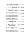
- FIG. 1 is a diagram showing a laminate manufactured by a method for manufacturing a laminate according to an embodiment of the present invention. It is a figure showing the flow of a manufacturing method of a layered product concerning one embodiment of the present invention. 1 is a diagram showing an example of an autoclave used in a method for manufacturing a laminate according to an embodiment of the present invention.
- FIG. 1 is a diagram showing a laminate 1 manufactured by the manufacturing method of this embodiment.
- the laminate 1 includes a metal base substrate 2, an insulating layer 3, and a circuit pattern 4.
- the metal base substrate 2 is formed of, for example, a metal such as copper, aluminum, or iron (it may be a single metal or an alloy).
- the metal base substrate 2 may have a single-layer structure or a multi-layer structure, and may be composed of a single member or a combination of a plurality of members.
- the metal base substrate 2 of this embodiment is plate-shaped, it may also be a heat sink provided with comb-shaped fins.
- the metal base substrate 2 may include a structure that improves the effect of dissipating heat to the outside, for example, a vapor chamber or a heat pipe may be embedded in a metal plate.
- the insulating layer 3 is made of an insulating material and is provided to cover the surface of the metal base substrate 2.
- the insulating layer 3 may cover the entire surface of the metal base substrate 2, or may cover a part of the surface.
- the insulating layer 3 is formed from a resin composition containing a thermosetting resin.
- a thermosetting resin examples include epoxy resin, phenol resin, melamine resin, urea resin, unsaturated polyester resin, alkyd resin, and cyanate resin.
- One type of thermosetting resin may be used alone, or two or more types may be used in combination.
- epoxy resin it is possible to use monomers, oligomers, and polymers in general that have two or more epoxy groups in one molecule, regardless of their molecular weight and molecular structure.
- epoxy resins include bisphenol A epoxy resin, bisphenol F epoxy resin, bisphenol E epoxy resin, bisphenol S epoxy resin, hydrogenated bisphenol A epoxy resin, and bisphenol M epoxy resin (4 , 4'-(1,3-phenylene diisopridiene) bisphenol type epoxy resin), bisphenol P type epoxy resin (4,4'-(1,4-phenylene diisopridiene) bisphenol type epoxy resin), bisphenol Bisphenol type epoxy resins such as Z type epoxy resin (4,4'-cyclohexydiene bisphenol type epoxy resin); phenol novolak type epoxy resin, brominated phenol novolac type epoxy resin, cresol novolak type epoxy resin, tetraphenol-based ethane type Novolak-type epoxy resins such as novolac-type epoxy resins and novolak-type epoxy resins having a
- Examples include a copolymer with a compound having an ethylenically unsaturated double bond, an epoxy resin having a butadiene structure, a diglycidyl ether of bisphenol, a diglycidyl ether of naphthalene diol, and a glycidyl ether of phenols.
- One type of epoxy resin may be used alone, or two or more types may be used in combination.
- a curing agent is blended into the resin composition of this embodiment.
- the curing agent is selected depending on the type of thermosetting resin, and is not particularly limited as long as it reacts with the thermosetting resin.
- examples of the curing agent include amine curing agents, imidazole curing agents, and phenol curing agents.
- a filler (inorganic filler) is blended into the resin composition of this embodiment.
- the filler preferably has excellent insulation properties and high thermal conductivity, and examples thereof include aluminum oxide, silica, aluminum nitride, boron nitride, silicon nitride, and magnesium oxide.
- One type of filler may be used alone, or two or more types may be used in combination.
- a curing accelerator is blended into the resin composition of this embodiment.
- the curing accelerator is not particularly limited, and examples thereof include benzoxazine compounds, borate complexes, zinc naphthenate, cobalt naphthenate, tin octylate, cobalt octylate, cobalt(II) bisacetylacetonate, and triacetylacetonate.
- examples include organic metal salts such as nertocobalt (III), phenol compounds such as phenol, bisphenol A, and nonylphenol, tertiary amines, tertiary amine salts, phosphine, and phosphonium salts.
- a solvent is blended into the resin composition of this embodiment.
- the solvent is not particularly limited, and examples include N-methylpyrrolidone, dimethylacetamide, tetrafluoroisopropanol, methylethylketone, ethylene diglycol acetate, propylene glycol monomethyl ether acetate, methyl isobutyl ketone, ethylene glycol monomethyl ether, tetrahydrofuran, and chloroform. , toluene, xylene, acetone, dioxane, dimethyl sulfoxide and the like.
- the resin composition may contain additives.
- additives include stabilizers, ion scavengers, flexibility imparting agents, and the like.
- the circuit pattern 4 is obtained by forming a predetermined pattern using a conductive material.
- a conductive material examples include copper and aluminum metal plates.
- the thickness of the metal plate (the thickness of the circuit pattern 4) is 0.8 mm or more. Note that there is no particular restriction on the upper limit of the thickness of the metal plate (thickness of the circuit pattern 4), but as an example, it is 2.0 mm or less.
- Methods for forming a predetermined pattern using a metal plate include, for example, a method in which a mask pattern is formed on the metal plate and the exposed portion of the metal plate is removed by etching, and a method in which the metal plate is punched out using a mold. can be mentioned.
- thermosetting resin and a curing agent are placed in a container and stirred at a predetermined temperature for a predetermined time. This allows the thermosetting resin and the curing agent to react.
- the thermosetting resin and curing agent that react in the first step can be made into a prepolymer state, but this depends on the degree of curing of the thermosetting resin in the step described later. It is not necessary to make the thermosetting resin and the curing agent into a prepolymer state in the first step.
- the stirred thermosetting resin, a curing agent, a filler, a curing accelerator, and a solvent are mixed, thereby producing a resin composition.
- the resin composition in the second step is in a semi-cured state.
- the produced resin composition is applied to the surface of a thin base material and further dried to evaporate the solvent.
- the base material is not particularly limited as long as it can be peeled off from the resin composition in the step described below, but as an example, a long PET sheet can be used.
- there is no particular restriction on implementing the third step but there is a feeding section where the elongated base material is fed out, and a coating section which is provided on the downstream side in the feeding direction and coats the resin composition on the front side of the substrate.
- the fourth step the elongated base material coated with the resin composition is cut into a predetermined size to form a sheet material in which the resin composition and the base material are laminated. Note that in the third step, when using a base material that has been cut to a predetermined size in advance, the fourth step can be omitted.
- the resin composition coated on the base material is heated at a predetermined temperature for a predetermined time.
- the molecular weight (weight average molecular weight) of the semi-cured resin composition can be increased.
- the molecular weight of the resin composition increases in the steps after the fifth step, but by increasing the molecular weight of the resin composition in advance in the fifth step, the overall time required for manufacturing the laminate 1 is shortened. be able to.
- the fifth step may be omitted.
- One specific example for carrying out the fifth step is to prepare a plurality of sheet materials in which the above-described resin composition and base material are laminated, and to heat them together in a heating furnace.
- the sixth step compressive force is applied to the semi-cured resin composition.
- the resin composition before carrying out the sixth step is in a state that contains many voids inside due to drying in the third step, but by carrying out the sixth step, the density can be increased and voids can be reduced, Furthermore, when it is formed as an insulating layer through the steps described below, high insulating properties can be obtained.
- the above-mentioned sheet material is stacked on the metal base substrate 2 shown in FIG.
- the metal base substrate 2 is not necessarily required in performing the sixth step; for example, a separately prepared base material and the above-mentioned sheet material may be stacked and pressed together, or a single sheet material may be pressed. It's okay.
- gas can be discharged from the semi-cured resin composition by carrying out the step (eighth step) using an autoclave, which will be described later. If the temperature is too high, gas may not be sufficiently discharged from the resin composition even if the eighth step is performed. Furthermore, even if the eighth step is carried out in a state where the resin composition has a low density and contains many voids inside, it may be difficult to reduce the voids to the extent that a sufficient withstand voltage can be obtained.
- the weight average molecular weight of the resin composition was further investigated, more favorable results were obtained when the density was 90% or less, and even more favorable results were obtained when the density was 95% or less.
- the weight average molecular weight is a polystyrene equivalent value measured by GPC (gel permeation chromatography) method.
- the base material is peeled off from the semi-cured resin composition transferred to the metal base substrate 2, or if the resin composition is not transferred to the metal base substrate 2, after the resin composition is transferred.
- the base material is peeled off from the resin composition.
- the circuit pattern 4 shown in FIG. 1 is superimposed on the resin composition to form a pre-pressure laminate 1A (see FIG. 3).
- the circuit pattern superimposed on the resin composition may be hot-pressed to temporarily adhere the circuit pattern to the resin composition.
- the reference numeral 3A shown in FIG. 3 indicates a semi-cured resin composition.
- the semi-cured resin composition 3A laminated on the pre-pressure laminate 1A is cured using an autoclave 10 and a film (bagging film) 11 having a configuration as shown in FIG. 3, for example.
- the autoclave 10 of this embodiment includes a main body 10a and a lid 10b.
- the main body 10a is provided with an exhaust passage 10c
- the lid 10b is provided with a pressurization passage 10d.
- a heater or the like for increasing the temperature inside the autoclave 10 is provided on both or one of the main body 10a and the lid 10b.
- the film 11 is preferably a fluororesin film that is flexible and has excellent releasability. Further, in carrying out this step, the case is not limited to the case where only the film 11 is used, and a cushioning material or a breather cloth may be used in combination with the film 11.
- the pre-pressure laminate 1A is placed on the main body 10a and covered with the film 11, the lid 10b is closed, and the film 11 is sandwiched between the main body 10a and the lid 10b.
- the inside of the film 11 is evacuated by suctioning through the exhaust passage 10c, and pressurized gas (air, nitrogen, etc.) is fed through the pressurization passage 10d to increase the pressure inside the autoclave 10.
- pressurized gas air, nitrogen, etc.
- the temperature inside the autoclave 10 is increased by a heater.
- the pressure inside the autoclave 10 is preferably 0.8 MPa or more and 3.0 MPa or less, and the temperature inside the autoclave 10 is preferably 100°C or more and 350°C or less, and the temperature inside the autoclave 10 is preferably 100°C or more and 350°C or less.
- the time for maintaining the pressure and temperature is preferably 1 minute or more and 90 minutes or less. Note that the pressure and temperature inside the autoclave 10 can be changed for the purpose of properly curing the resin composition 3A, and may be set to be kept constant during the above-mentioned time. Alternatively, it may be set to change over time.
- the film 11 not only comes into close contact with the surface of the conductive parts (metal parts) that constitute the circuit pattern 4, but also penetrates into the gaps located between adjacent conductive parts. , it also adheres closely to the resin composition 3A exposed in the gap.
- gas gas contained in the voids and residual solvent, volatile low molecular weight components, effective reactions
- gases etc. generated along with the process can be discharged.
- the laminate 1 taken out from the autoclave 10 is fully cured.
- One specific example of carrying out the ninth step is to place the laminate 1 taken out from the autoclave 10 into a heating furnace and heat it at a predetermined temperature for a predetermined time. Thereby, the semi-cured resin composition 3A can be fully cured.
- the 9th step is performed when the main curing of the resin composition 3A is not completed in the 8th step, and when the main curing of the resin composition 3A is completed in the 8th step, the 9th step is performed. Omitted.
- the resin composition 3A is in a fully cured state and the laminate 1 on which the insulating layer 3 is formed is cleaned, and various tests are performed.
- a bisphenol A type epoxy resin (manufactured by DIC) was prepared as a thermosetting resin, diethyltoluenediamine (manufactured by Lonza) was prepared as a curing agent, and aluminum oxide, boron nitride aggregates, and boron nitride were used as fillers. Fine powder was prepared, triphenylphosphine (manufactured by Hokko Chemical Industry Co., Ltd.) was prepared as a curing accelerator, and ethyl 3-ethoxypropionate was prepared as a solvent.
- thermosetting resin and curing agent were stirred at 70° C. for 11 hours to form a prepolymer state (first step).
- the above-described filler, curing accelerator, and solvent were added to the thermosetting resin in the prepolymer state and mixed in a mixer to produce a semi-cured resin composition (second step).
- the weight average molecular weight of the resin composition after the second step was measured.
- the measured weight average molecular weight is a polystyrene equivalent value measured by GPC (gel permeation chromatography) method. Further, measurements were performed using tetrahydrofuran (THF) as a mobile phase.
- Measurement device Waters e2695 separation module Differential refractive index (RI) detector: Waters 2414 RI Detector Column: TSKgel guardcolumnH Column: TSKgel G1000H Column: TSKgel G2000H Column: TSKgel G3000H
- the weight average molecular weight of the resin composition after the second step was 487.
- the produced resin composition was applied to a long PET sheet, and this was heated at 80° C. for 40 minutes (third step). Thereafter, the PET sheet coated with the resin composition was cut into a predetermined size (fourth step). Thereafter, the cut sheet material was heated at 80° C. for 20 minutes (fifth step).
- the weight average molecular weight and density of the resin composition after the fifth step were measured.
- the method for measuring the weight average molecular weight is the same as the method for measuring after the second step.
- the density was measured by the Archimedes method using an electronic balance HR-250AZ manufactured by A&D Co., Ltd. and a specific gravity measurement kit AD-1653.
- the weight average molecular weight of the resin composition at this time was 1700, and the density was 1.87 g/cm 3 .
- the actual density of the insulating layer when the resin composition is fully cured through the 10th step is 2.10 g/cm 3 as measured by the above-mentioned Archimedes method.
- the sheet material after the fifth step was stacked on the metal base substrate 2 with the resin composition in contact with the metal base substrate 2, and this was placed inside a vacuum press device. Then, while the interior of the device was in a vacuum atmosphere and the temperature was 90° C., the stacked metal base substrate and sheet material were pressed at 23 MPa for 30 seconds (sixth step).
- the weight average molecular weight and density of the resin composition after the sixth step were measured.
- the weight average molecular weight and density are measured in the same manner as after the fifth step.
- the weight average molecular weight of the resin composition at this time was 1900, and the density was 2.00 g/cm 3 . That is, in this example, the rate of increase in the weight average molecular weight of the resin composition after the step of applying compressive force is ((1900-1700)/1700) x 100 based on the rate before the step of applying compressive force. Since it is calculated in %, it is 11.8%. Further, in this example, the density of the resin composition is calculated as (2.00/2.10) x 100% after the step of applying compressive force based on the actual density of the insulating layer, so it is 95.2 %.
- the PET sheet was peeled off from the semi-cured resin composition transferred to the metal base substrate 2, and the circuit pattern 4 (thickness 1 mm) was further superimposed to form a pre-pressure laminate (seventh step).
- the pre-pressure laminate is placed on the main body of the autoclave and covered with a film. After closing the lid of the autoclave, the inside of the film was evacuated, and the pressure and temperature inside the autoclave were increased (eighth step).
- condition A The eighth step was carried out under two conditions: condition A and condition B below. The results will be discussed later.
- condition A> The temperature inside the autoclave is maintained at 160° C. for 18 minutes.
- the internal pressure is 0 MPa until 5 minutes have elapsed from the start, and 3 MPa until 18 minutes (13 minutes) after the 5 minutes have elapsed.
- ⁇ Condition B> The temperature inside the autoclave is maintained at 180° C. for 11.5 minutes.
- the internal pressure is 0 MPa until 5 minutes have elapsed from the start, and the pressure is increased to 3 MPa until 11.5 minutes (6.5 minutes) after the 5 minutes have elapsed.
- the laminate taken out from the autoclave was heated at 185° C. in a non-pressurized (atmospheric pressure) state for 1 hour (9th step). Thereafter, cleaning was performed and a predetermined inspection was performed (10th step).
- Laminate 1A Laminate before pressure bonding 2: Metal base substrate 3: Insulating layer 3A: Semi-cured resin composition 4: Circuit pattern 10: Autoclave 11: Film
Abstract
The present invention pertains to a laminate using a circuit pattern having a thickness of at least 0.8 mm, and proposes a production method that is for the laminate and that is capable of preventing defects from occurring in an insulating layer. The production method is for a laminate (1) obtained by laminating a metal base substrate (2), an insulating layer (3) formed by curing a resin composition, and a circuit pattern (4) having a thickness of at least 1 mm, the method comprising: a step for preparing a pre-pressure bonded laminate (1A) in which a semi-cured resin composition (3A) is interposed between the metal base substrate (2) and the circuit pattern (4); a step for covering the pre-pressure bonded laminate (1A) with a film (11), and placing the resultant laminate inside an autoclave (10); and a step for degassing the inside of the film (11) and increasing the temperature and pressure inside of the autoclave (10) to cure the semi-cured resin composition (3A).
Description
本発明は、積層体の製造方法に関する。
The present invention relates to a method for manufacturing a laminate.
従前より、半導体チップ等の電子部品が実装される回路基板として、金属ベース基板と、絶縁層と、回路パターンとが積層された積層体が知られている(例えば特許文献1参照)。この種の積層体は、例えば樹脂とフィラーを配合させた樹脂組成物を準備し、金属ベース基板に樹脂組成物を塗布して予備硬化を行った後、この樹脂組成物上に回路パターンを配置して熱プレスを行うことによって製造される。
A laminate in which a metal base substrate, an insulating layer, and a circuit pattern are stacked has been known as a circuit board on which electronic components such as semiconductor chips are mounted (for example, see Patent Document 1). For this type of laminate, for example, a resin composition containing a resin and a filler is prepared, the resin composition is applied to a metal base substrate and precured, and then a circuit pattern is placed on the resin composition. It is manufactured by heat pressing.
近年は高輝度LEDやパワーモジュールのような大電流が流れる電子部品を使用する機会が増えている。この種の電子部品を使用することが可能な大電流に対応した積層体を得るには、抵抗値を下げるとともに大電流を流した際に十分な放熱性が確保されるように、回路パターンの厚みを厚くすることが有効である。
In recent years, opportunities to use electronic components such as high-intensity LEDs and power modules that flow large currents have increased. In order to obtain a laminate that can handle large currents that can be used with this type of electronic component, the circuit pattern must be designed to lower the resistance value and ensure sufficient heat dissipation when large currents are passed. It is effective to increase the thickness.
ところで積層体の製造にあたって熱プレスを行う場合、回路パターンを構成する導通部分(金属部分)と接触する樹脂組成物は加圧される一方、隣り合う導通部分同士の間に位置する隙間の部分は樹脂組成物に接触していないため、この隙間部分において樹脂組成物は加圧が不足気味になる。すなわち熱プレスを行う際、樹脂組成物は、導通部分との接触の有り無しによって受ける圧力は不均一になる。ここで隙間部分が位置する部位では、加圧不足に伴って樹脂組成物内に含まれる気体を排出できずにボイドが多数生成され、これにより絶縁性が確保できないおそれがある。特に回路パターンを厚肉化した場合は、この隙間部分の深さが深くなって加圧不足が顕著になるため、このような不具合が生じやすくなる。また導通部分が位置する部位においては、導通部分の端部によって樹脂組成物が強く押される(或いは導通部分の端部を境に隙間部分と導通部分との間で急激な圧力変化が生じる)ことにより、絶縁層として形成した際に割れが生じることがある。
By the way, when hot pressing is used to manufacture a laminate, the resin composition that comes into contact with the conductive parts (metallic parts) that make up the circuit pattern is pressurized, while the gap between adjacent conductive parts is pressed. Since it is not in contact with the resin composition, the resin composition tends to be insufficiently pressurized in this gap portion. That is, when hot pressing is performed, the pressure applied to the resin composition becomes uneven depending on whether or not it comes into contact with the conductive portion. Here, in the area where the gap is located, due to insufficient pressurization, the gas contained in the resin composition cannot be discharged and a large number of voids are generated, and as a result, there is a possibility that insulation cannot be ensured. Particularly when the circuit pattern is made thicker, the depth of this gap becomes deeper and insufficient pressurization becomes noticeable, making it more likely that such problems will occur. In addition, in the area where the conductive part is located, the resin composition is strongly pressed by the end of the conductive part (or a sudden pressure change occurs between the gap part and the conductive part with the end of the conductive part as a border). Therefore, cracks may occur when formed as an insulating layer.
なお、表面に凹凸があるものを熱プレスする際、凹凸を埋めるように作用するクッション材を用いることがある(例えば特許文献2参照)。しかし、上記のように隙間の深さが深くなると、このようなクッション材でも隙間の奥まで十分に入り込ませることは難しくなるため、加圧不足が解消しきれないことがあった。特に回路パターンの厚みが0.8mm以上になる場合は、このような不具合発生の頻度が高くなっていた。
Note that when hot-pressing an item with an uneven surface, a cushioning material that acts to fill in the unevenness may be used (see, for example, Patent Document 2). However, as the depth of the gap increases as described above, it becomes difficult for even such a cushioning material to penetrate deep into the gap, and the insufficient pressurization may not be resolved. In particular, when the thickness of the circuit pattern is 0.8 mm or more, the frequency of occurrence of such problems increases.
このような問題点に鑑み、本発明は、厚みが0.8mm以上になる回路パターンを用いた積層体に関し、絶縁層で生じる不具合を防止することができる積層体の製造方法を提供することを目的とする。
In view of these problems, the present invention aims to provide a method for manufacturing a laminate that can prevent defects occurring in the insulating layer regarding a laminate using a circuit pattern with a thickness of 0.8 mm or more. purpose.
本発明は、金属ベース基板と、樹脂組成物を硬化させて形成される絶縁層と、厚みが0.8mm以上になる回路パターンとが積層された積層体の製造方法であって、前記金属ベース基板と前記回路パターンの間に半硬化状態の前記樹脂組成物が介在された圧着前積層体を準備する工程と、前記圧着前積層体をフィルムで被覆してオートクレーブの内部に配置する工程と、前記フィルムの内部を排気するとともに前記オートクレーブの内部の温度及び圧力を上昇させて半硬化状態の前記樹脂組成物を硬化させる工程と、を含む積層体の製造方法である。
The present invention provides a method for manufacturing a laminate in which a metal base substrate, an insulating layer formed by curing a resin composition, and a circuit pattern having a thickness of 0.8 mm or more are laminated, a step of preparing a pre-compression laminate in which the resin composition in a semi-cured state is interposed between the substrate and the circuit pattern; a step of covering the pre-compression laminate with a film and placing it inside an autoclave; The method for producing a laminate includes the steps of evacuating the inside of the film and increasing the temperature and pressure inside the autoclave to cure the resin composition in a semi-cured state.
上述した製造方法は、前記圧着前積層体を準備する工程を実施する前に行われ、半硬化状態の前記樹脂組成物に圧縮力を付与する工程を含むことが好ましい。
It is preferable that the manufacturing method described above is carried out before the step of preparing the pre-pressure laminate, and includes a step of applying compressive force to the resin composition in a semi-cured state.
また上述した製造方法において、半硬化状態の前記樹脂組成物における重量平均分子量の増加率は、前記圧縮力を付与する工程の前を基準として当該圧縮力を付与する工程の後では30%以下であることが好ましい。
Further, in the above-mentioned manufacturing method, the rate of increase in the weight average molecular weight of the resin composition in a semi-cured state is 30% or less after the step of applying the compressive force based on the value before the step of applying the compressive force. It is preferable that there be.
また上述した製造方法において、半硬化状態の前記樹脂組成物の密度は、前記絶縁層の実密度を基準として前記圧縮力を付与する工程の後では85%以上であることが好ましい。
Furthermore, in the above manufacturing method, the density of the resin composition in a semi-cured state is preferably 85% or more based on the actual density of the insulating layer after the step of applying the compressive force.
本発明に係る積層体の製造方法によれば、厚みが0.8mm以上になる回路パターンを用いた積層体において、絶縁層で生じる不具合を防止することができる。
According to the method for manufacturing a laminate according to the present invention, it is possible to prevent problems occurring in the insulating layer in a laminate using a circuit pattern having a thickness of 0.8 mm or more.
以下、添付図面を参照しながら本発明に係る積層体の製造方法の一実施形態について説明する。なお、添付図面に示した図は模式的なものであり、各部分の厚みや幅、各部分同士の比率等は、実際に実施されるものとは異なる場合がある。
Hereinafter, one embodiment of the method for manufacturing a laminate according to the present invention will be described with reference to the accompanying drawings. Note that the figures shown in the accompanying drawings are schematic, and the thickness and width of each part, the ratio of each part, etc. may differ from those actually implemented.
図1は、本実施形態の製造方法により製造された積層体1について示した図である。積層体1は、金属ベース基板2と、絶縁層3と、回路パターン4を備える。
FIG. 1 is a diagram showing a laminate 1 manufactured by the manufacturing method of this embodiment. The laminate 1 includes a metal base substrate 2, an insulating layer 3, and a circuit pattern 4.
金属ベース基板2は、例えば銅、アルミニウム、鉄等の金属(単体金属でもよいし合金でもよい)により形成される。金属ベース基板2は、単層構造でも多層構造でもよく、また単一の部材で構成してもよいし複数の部材を組み合わせて構成してもよい。本実施形態の金属ベース基板2は、板状になるものであるが、櫛状のフィンを設けたヒートシンクでもよい。また金属ベース基板2は、熱を外部に放出させる効果を向上させる構成を含むものでもよく、例えば金属板にベイパーチャンバーやヒートパイプを埋設したものでもよい。
The metal base substrate 2 is formed of, for example, a metal such as copper, aluminum, or iron (it may be a single metal or an alloy). The metal base substrate 2 may have a single-layer structure or a multi-layer structure, and may be composed of a single member or a combination of a plurality of members. Although the metal base substrate 2 of this embodiment is plate-shaped, it may also be a heat sink provided with comb-shaped fins. Further, the metal base substrate 2 may include a structure that improves the effect of dissipating heat to the outside, for example, a vapor chamber or a heat pipe may be embedded in a metal plate.
絶縁層3は、絶縁性を有する素材で形成され、金属ベース基板2の表面を覆うように設けられる。絶縁層3は、金属ベース基板2の表面全体を覆っていてもよいし、表面の一部を覆っていてもよい。
The insulating layer 3 is made of an insulating material and is provided to cover the surface of the metal base substrate 2. The insulating layer 3 may cover the entire surface of the metal base substrate 2, or may cover a part of the surface.
絶縁層3は、熱硬化性樹脂を含有する樹脂組成物から形成される。熱硬化性樹脂としては、例えば、エポキシ樹脂、フェノール樹脂、メラミン樹脂、ユリア樹脂、不飽和ポリエステル樹脂、アルキド樹脂、シアネート樹脂等が挙げられる。熱硬化性樹脂として1種を単独で使用してもよいし、2種以上を併用してもよい。
The insulating layer 3 is formed from a resin composition containing a thermosetting resin. Examples of the thermosetting resin include epoxy resin, phenol resin, melamine resin, urea resin, unsaturated polyester resin, alkyd resin, and cyanate resin. One type of thermosetting resin may be used alone, or two or more types may be used in combination.
エポキシ樹脂としては、その分子量、分子構造に関係なく、1分子内にエポキシ基を2個以上有するモノマー、オリゴマー、ポリマー全般を使用することが可能である。このようなエポキシ樹脂の具体例としては、ビスフェノールA型エポキシ樹脂、ビスフェノールF型エポキシ樹脂、ビスフェノールE型エポキシ樹脂、ビスフェノールS型エポキシ樹脂、水添ビスフェノールA型エポキシ樹脂、ビスフェノールM型エポキシ樹脂(4,4'-(1,3-フェニレンジイソプリジエン)ビスフェノール型エポキシ樹脂)、ビスフェノールP型エポキシ樹脂(4,4'-(1,4-フェニレンジイソプリジエン)ビスフェノール型エポキシ樹脂)、ビスフェノールZ型エポキシ樹脂(4,4'-シクロヘキシジエンビスフェノール型エポキシ樹脂)などのビスフェノール型エポキシ樹脂;フェノールノボラック型エポキシ樹脂、臭素化フェノールノボラック型エポキシ樹脂、クレゾールノボラック型エポキシ樹脂、テトラフェノール基エタン型ノボラック型エポキシ樹脂、縮合環芳香族炭化水素構造を有するノボラック型エポキシ樹脂などのノボラック型エポキシ樹脂;ビフェニル型エポキシ樹脂;キシリレン型エポキシ樹脂、ビフェニルアラルキル型エポキシ樹脂などのアラルキル型エポキシ樹脂;ナフチレンエーテル型エポキシ樹脂、ナフトール型エポキシ樹脂、ナフタレン型エポキシ樹脂、ナフタレンジオール型エポキシ樹脂、2官能ないし4官能エポキシ型ナフタレン樹脂、ビナフチル型エポキシ樹脂、ナフタレンアラルキル型エポキシ樹脂などのナフタレン骨格を有するエポキシ樹脂;アントラセン型エポキシ樹脂;フェノキシ型エポキシ樹脂;ジシクロペンタジエン型エポキシ樹脂;ノルボルネン型エポキシ樹脂;アダマンタン型エポキシ樹脂;フルオレン型エポキシ樹脂、リン含有エポキシ樹脂、脂環式エポキシ樹脂、脂肪族鎖状エポキシ樹脂、ビスフェノールAノボラック型エポキシ樹脂、ビキシレノール型エポキシ樹脂、トリフェノールメタン型エポキシ樹脂、トリヒドロキシフェニルメタン型エポキシ樹脂、テトラフェニロールエタン型エポキシ樹脂、トリグリシジルイソシアヌレートなどの複素環式エポキシ樹脂;N,N,N',N'-テトラグリシジルメタキシレンジアミン、N,N,N',N'-テトラグリシジルビスアミノメチルシクロヘキサン、N,N-ジグリシジルアニリンなどのグリシジルアミン類や、グリシジル(メタ)アクリレートとエチレン性不飽和二重結合を有する化合物との共重合物、ブタジエン構造を有するエポキシ樹脂、ビスフェノールのジグリシジルエーテル化物、ナフタレンジオールのジグリシジルエーテル化物、フェノール類のグリシジルエーテル化物などが挙げられる。エポキシ樹脂として1種を単独で使用してもよいし、2種以上を併用してもよい。
As the epoxy resin, it is possible to use monomers, oligomers, and polymers in general that have two or more epoxy groups in one molecule, regardless of their molecular weight and molecular structure. Specific examples of such epoxy resins include bisphenol A epoxy resin, bisphenol F epoxy resin, bisphenol E epoxy resin, bisphenol S epoxy resin, hydrogenated bisphenol A epoxy resin, and bisphenol M epoxy resin (4 , 4'-(1,3-phenylene diisopridiene) bisphenol type epoxy resin), bisphenol P type epoxy resin (4,4'-(1,4-phenylene diisopridiene) bisphenol type epoxy resin), bisphenol Bisphenol type epoxy resins such as Z type epoxy resin (4,4'-cyclohexydiene bisphenol type epoxy resin); phenol novolak type epoxy resin, brominated phenol novolac type epoxy resin, cresol novolak type epoxy resin, tetraphenol-based ethane type Novolak-type epoxy resins such as novolac-type epoxy resins and novolak-type epoxy resins having a condensed ring aromatic hydrocarbon structure; biphenyl-type epoxy resins; aralkyl-type epoxy resins such as xylylene-type epoxy resins and biphenylaralkyl-type epoxy resins; naphthylene ether Epoxy resins having a naphthalene skeleton such as type epoxy resins, naphthol type epoxy resins, naphthalene type epoxy resins, naphthalene diol type epoxy resins, difunctional to tetrafunctional epoxy type naphthalene resins, binaphthyl type epoxy resins, naphthalene aralkyl type epoxy resins; anthracene type epoxy resin; phenoxy type epoxy resin; dicyclopentadiene type epoxy resin; norbornene type epoxy resin; adamantane type epoxy resin; fluorene type epoxy resin, phosphorus-containing epoxy resin, alicyclic epoxy resin, aliphatic chain epoxy resin, bisphenol A Heterocyclic epoxy resins such as novolak epoxy resins, bixylenol epoxy resins, triphenolmethane epoxy resins, trihydroxyphenylmethane epoxy resins, tetraphenylolethane epoxy resins, triglycidyl isocyanurate; N, N , N',N'-tetraglycidyl metaxylene diamine, N,N,N',N'-tetraglycidylbisaminomethylcyclohexane, N,N-diglycidylaniline, and glycidyl (meth)acrylate. Examples include a copolymer with a compound having an ethylenically unsaturated double bond, an epoxy resin having a butadiene structure, a diglycidyl ether of bisphenol, a diglycidyl ether of naphthalene diol, and a glycidyl ether of phenols. One type of epoxy resin may be used alone, or two or more types may be used in combination.
本実施形態の樹脂組成物には、硬化剤が配合される。硬化剤は、熱硬化性樹脂の種類に応じて選択され、これと反応するものであれば特に限定されない。例えばエポキシ樹脂を使用する場合における硬化剤としては、アミン系硬化剤、イミダゾール系硬化剤、フェノール系硬化剤等が挙げられる。
A curing agent is blended into the resin composition of this embodiment. The curing agent is selected depending on the type of thermosetting resin, and is not particularly limited as long as it reacts with the thermosetting resin. For example, when using an epoxy resin, examples of the curing agent include amine curing agents, imidazole curing agents, and phenol curing agents.
また本実施形態の樹脂組成物には、フィラー(無機充填材)が配合される。フィラーは、絶縁性に優れかつ熱伝導率の高いものが好ましく、例えば、酸化アルミニウム、シリカ、窒化アルミニウム、窒化ホウ素、窒化ケイ素、酸化マグネシウム等が挙げられる。フィラーは、1種を単独で使用してもよいし、2種以上を併用してもよい。
Additionally, a filler (inorganic filler) is blended into the resin composition of this embodiment. The filler preferably has excellent insulation properties and high thermal conductivity, and examples thereof include aluminum oxide, silica, aluminum nitride, boron nitride, silicon nitride, and magnesium oxide. One type of filler may be used alone, or two or more types may be used in combination.
更に本実施形態の樹脂組成物には、硬化促進剤が配合される。硬化促進剤は、特に限定されるものではなく、例えば、ベンゾオキサジン化合物、ボレート錯体、ナフテン酸亜鉛、ナフテン酸コバルト、オクチル酸スズ、オクチル酸コバルト、ビスアセチルアセトナートコバルト(II)、トリアセチルアセトナートコバルト(III)等の有機金属塩、フェノール、ビスフェノールA、ノニルフェノール等のフェノール化合物、三級アミン、三級アミン塩、ホスフィン、ホスホニウム塩等が挙げられる。
Furthermore, a curing accelerator is blended into the resin composition of this embodiment. The curing accelerator is not particularly limited, and examples thereof include benzoxazine compounds, borate complexes, zinc naphthenate, cobalt naphthenate, tin octylate, cobalt octylate, cobalt(II) bisacetylacetonate, and triacetylacetonate. Examples include organic metal salts such as nertocobalt (III), phenol compounds such as phenol, bisphenol A, and nonylphenol, tertiary amines, tertiary amine salts, phosphine, and phosphonium salts.
また本実施形態の樹脂組成物には、溶剤が配合される。溶剤は、特に限定されるものではなく、例えば、N-メチルピロリドン、ジメチルアセトアミド、テトラフルオロイソプロパノール、メチルエチルケトン、エチレンジグリコールアセテート、プロピレングリコールモノメチルエーテルアセテート、メチルイソブチルケトン、エチレングリコールモノメチルエーテル、テトラヒドロフラン、クロロホルム、トルエン、キシレン、アセトン、ジオキサン、ジメチルスルホキシド等が挙げられる。
Additionally, a solvent is blended into the resin composition of this embodiment. The solvent is not particularly limited, and examples include N-methylpyrrolidone, dimethylacetamide, tetrafluoroisopropanol, methylethylketone, ethylene diglycol acetate, propylene glycol monomethyl ether acetate, methyl isobutyl ketone, ethylene glycol monomethyl ether, tetrahydrofuran, and chloroform. , toluene, xylene, acetone, dioxane, dimethyl sulfoxide and the like.
樹脂組成物には、添加剤を含有させてもよい。添加剤としては、安定剤、イオン捕捉剤、柔軟性付与材等が挙げられる。
The resin composition may contain additives. Examples of additives include stabilizers, ion scavengers, flexibility imparting agents, and the like.
回路パターン4は、導電性を有する素材を用いて所定のパターンを形成することにより得られる。このような素材としては、例えば銅やアルミニウムの金属板が挙げられる。金属板の厚み(回路パターン4の厚み)は0.8mm以上である。なお、金属板の厚み(回路パターン4の厚み)の上限に特に制限はないが、一例として2.0mm以下である。金属板を用いて所定のパターンを形成する手法としては、例えば金属板の上にマスクパターンを形成して金属板の露出部をエッチングによって除去する手法や、金型を用いて金属板を打ち抜く手法が挙げられる。
The circuit pattern 4 is obtained by forming a predetermined pattern using a conductive material. Examples of such materials include copper and aluminum metal plates. The thickness of the metal plate (the thickness of the circuit pattern 4) is 0.8 mm or more. Note that there is no particular restriction on the upper limit of the thickness of the metal plate (thickness of the circuit pattern 4), but as an example, it is 2.0 mm or less. Methods for forming a predetermined pattern using a metal plate include, for example, a method in which a mask pattern is formed on the metal plate and the exposed portion of the metal plate is removed by etching, and a method in which the metal plate is punched out using a mold. can be mentioned.
次に、積層体1の製造方法について、図2、図3を参照しながら説明する。
Next, a method for manufacturing the laminate 1 will be described with reference to FIGS. 2 and 3.
まず図2に示した第1工程を実施する。第1工程では、熱硬化性樹脂と硬化剤を容器に入れ、所定の温度で所定時間攪拌させる。これにより、熱硬化性樹脂と硬化剤を反応させることができる。なお、攪拌時の温度及び攪拌時間によっては、第1工程で反応する熱硬化性樹脂と硬化剤をプレポリマー状態にすることができるが、これは後述する工程での熱硬化性樹脂の硬化度によって適宜選択すればよく、必ずしも第1工程において熱硬化性樹脂と硬化剤をプレポリマー状態にする必要はない。
First, the first step shown in FIG. 2 is performed. In the first step, a thermosetting resin and a curing agent are placed in a container and stirred at a predetermined temperature for a predetermined time. This allows the thermosetting resin and the curing agent to react. Depending on the temperature and stirring time during stirring, the thermosetting resin and curing agent that react in the first step can be made into a prepolymer state, but this depends on the degree of curing of the thermosetting resin in the step described later. It is not necessary to make the thermosetting resin and the curing agent into a prepolymer state in the first step.
第2工程では、攪拌させた熱硬化性樹脂と硬化剤、フィラー、硬化促進剤、及び溶剤を混合させ、これにより樹脂組成物を生成する。なお第2工程における樹脂組成物は、半硬化状態にある。
In the second step, the stirred thermosetting resin, a curing agent, a filler, a curing accelerator, and a solvent are mixed, thereby producing a resin composition. Note that the resin composition in the second step is in a semi-cured state.
そして第3工程では、生成した樹脂組成物を薄手の基材の表面に塗工し、更に乾燥させて溶剤を揮発させる。基材は、後述する工程で樹脂組成物から剥離できるものであれば特に制限はないが、一例として長尺状のPETシートを用いることができる。また第3工程を実施するにあたって特に制限はないが、長尺状の基材が送り出される送り出し部と、送り出し方向下流側に設けられ、樹脂組成物を基材の表側に塗工する塗工部と、送り出し方向上流側に設けられ、通過する樹脂組成物を所定の温度で加熱する加熱部とを備える装置を用いる場合は、樹脂組成物の塗工と乾燥を連続的に行うことができるため、第3工程を効率よく実施することができる点で優れている。
In the third step, the produced resin composition is applied to the surface of a thin base material and further dried to evaporate the solvent. The base material is not particularly limited as long as it can be peeled off from the resin composition in the step described below, but as an example, a long PET sheet can be used. In addition, there is no particular restriction on implementing the third step, but there is a feeding section where the elongated base material is fed out, and a coating section which is provided on the downstream side in the feeding direction and coats the resin composition on the front side of the substrate. When using a device equipped with a heating section provided on the upstream side in the feeding direction and heating the passing resin composition at a predetermined temperature, coating and drying of the resin composition can be performed continuously. , is excellent in that the third step can be carried out efficiently.
第4工程では、樹脂組成物が塗工されている長尺状の基材を所定の大きさにカットし、樹脂組成物と基材が積層された枚葉状のシート材を形成する。なお第3工程において、予め所定の大きさにカットされた基材を用いる場合は、第4工程は省略可能である。
In the fourth step, the elongated base material coated with the resin composition is cut into a predetermined size to form a sheet material in which the resin composition and the base material are laminated. Note that in the third step, when using a base material that has been cut to a predetermined size in advance, the fourth step can be omitted.
そして第5工程では、基材に塗工した樹脂組成物を所定の温度で所定時間加熱する。これにより、半硬化状態の樹脂組成物の分子量(重量平均分子量)を上げることができる。なお、第5工程以降の工程でも樹脂組成物の分子量は上がっていくが、第5工程で予め樹脂組成物の分子量を上げておくことにより、積層体1の製造に要する全体の時間を短縮することができる。また、第5工程よりも前の工程で必要とする樹脂組成物の分子量が既に確保されている場合は、第5工程を省略してもよい。第5工程を実施するための一具体例としては、上述した樹脂組成物と基材が積層されたシート材を複数枚準備しておき、それらをまとめて加熱炉で加熱することが挙げられる。
In the fifth step, the resin composition coated on the base material is heated at a predetermined temperature for a predetermined time. Thereby, the molecular weight (weight average molecular weight) of the semi-cured resin composition can be increased. Note that the molecular weight of the resin composition increases in the steps after the fifth step, but by increasing the molecular weight of the resin composition in advance in the fifth step, the overall time required for manufacturing the laminate 1 is shortened. be able to. Further, if the molecular weight of the resin composition required in a step before the fifth step has already been secured, the fifth step may be omitted. One specific example for carrying out the fifth step is to prepare a plurality of sheet materials in which the above-described resin composition and base material are laminated, and to heat them together in a heating furnace.
第6工程では、半硬化状態の樹脂組成物に圧縮力を付与する。第6工程を実施する前における樹脂組成物は、第3工程での乾燥によって内部に空隙を多く含む状態にあるが、第6工程を実施することによって密度が高まって空隙を減らすことができ、ひいては後述する工程を経て絶縁層として形成した際に高い絶縁性を得ることができる。第6工程を実施するための一具体例としては、上述したシート材を、図1に示した金属ベース基板2に対して樹脂組成物が金属ベース基板2に接触する状態で重ね合わせ、これを、例えば真空プレス装置の内部に配置した後、この装置の内部が真空雰囲気で且つ所定の温度になる状態で、重ね合せた金属ベース基板2とシート材を押圧することが挙げられる。これにより、半硬化状態の樹脂組成物を金属ベース基板2に転写させるとともにこの樹脂組成物に圧縮力を付与することができる。なお、第6工程を行うにあたって金属ベース基板2は必ずしも必要ではなく、例えば別に用意した基材と上述したシート材とを重ね合わせてこれを押圧してもよいし、単独のシート材を押圧してもよい。
In the sixth step, compressive force is applied to the semi-cured resin composition. The resin composition before carrying out the sixth step is in a state that contains many voids inside due to drying in the third step, but by carrying out the sixth step, the density can be increased and voids can be reduced, Furthermore, when it is formed as an insulating layer through the steps described below, high insulating properties can be obtained. As a specific example for carrying out the sixth step, the above-mentioned sheet material is stacked on the metal base substrate 2 shown in FIG. 1 in a state where the resin composition is in contact with the metal base substrate 2, and For example, after placing the metal base substrate 2 in a vacuum press apparatus, the stacked metal base substrate 2 and the sheet material are pressed while the inside of the apparatus is in a vacuum atmosphere and at a predetermined temperature. Thereby, the semi-cured resin composition can be transferred to the metal base substrate 2 and compressive force can be applied to this resin composition. Note that the metal base substrate 2 is not necessarily required in performing the sixth step; for example, a separately prepared base material and the above-mentioned sheet material may be stacked and pressed together, or a single sheet material may be pressed. It's okay.
ところで、後述するオートクレーブを用いる工程(第8工程)を実施することによって半硬化状態の樹脂組成物から気体を排出することができるが、本願発明者が検討したところ、樹脂組成物の硬化が進みすぎている場合には、第8工程を実施しても樹脂組成物から気体を十分に排出できないことがあった。また樹脂組成物の密度が小さく内部に空隙が多く含まれている状態で第8工程を実施しても、十分な耐電圧を得られる程度まで空隙を減らし切ることが難しい場合があった。このような点に鑑み、樹脂組成物の分子量(重量平均分子量)と密度の最適な範囲について検討を重ねたところ、樹脂組成物の重量平均分子量の増加率に関し、第6工程の前(圧縮力を付与する前)を基準として第6工程の後(圧縮力を付与した後)で30%以下である場合は結果が良好であった。そして樹脂組成物の重量平均分子量の増加率について更に検討を重ねたところ、25%以下の場合はより好ましい結果が得られ、20%以下では更に好ましい結果が得られた。また樹脂組成物の密度は、最終的に形成される絶縁層の実密度を基準として第6工程の後(圧縮力を付与した後)で85%以上である場合は結果が良好であった。そして樹脂組成物の重量平均分子量の密度について更に検討を重ねたところ、90%以下の場合はより好ましい結果が得られ、95%以下では更に好ましい結果が得られた。なお重量平均分子量は、GPC(ゲルパーミエーションクロマトグラフィー)法により測定されたポリスチレン換算値である。
By the way, gas can be discharged from the semi-cured resin composition by carrying out the step (eighth step) using an autoclave, which will be described later. If the temperature is too high, gas may not be sufficiently discharged from the resin composition even if the eighth step is performed. Furthermore, even if the eighth step is carried out in a state where the resin composition has a low density and contains many voids inside, it may be difficult to reduce the voids to the extent that a sufficient withstand voltage can be obtained. In view of these points, we have repeatedly investigated the optimal range of the molecular weight (weight average molecular weight) and density of the resin composition, and found that the rate of increase in the weight average molecular weight of the resin composition is The result was good if it was 30% or less after the sixth step (after applying the compressive force) based on the reference value (before applying the compressive force). When the rate of increase in the weight average molecular weight of the resin composition was further investigated, more favorable results were obtained when it was 25% or less, and even more favorable results were obtained when it was 20% or less. Further, when the density of the resin composition was 85% or more after the sixth step (after applying compressive force) based on the actual density of the insulating layer to be finally formed, the result was good. When the density of the weight average molecular weight of the resin composition was further investigated, more favorable results were obtained when the density was 90% or less, and even more favorable results were obtained when the density was 95% or less. Note that the weight average molecular weight is a polystyrene equivalent value measured by GPC (gel permeation chromatography) method.
そして第7工程では、金属ベース基板2に転写させた半硬化状態の樹脂組成物から基材を剥離する、又は金属ベース基板2に樹脂組成物が転写されていない場合はこれを転写させた後に樹脂組成物から基材を剥離する。そして樹脂組成物に対して図1に示した回路パターン4を重ね合わせて、圧着前積層体1A(図3参照)を形成する。この工程において、樹脂組成物に重ね合わせた回路パターンを熱プレスし、樹脂組成物に対して回路パターンを仮接着させておいてもよい。なお図3に示した符合3Aは、半硬化状態の樹脂組成物を示す。
In the seventh step, the base material is peeled off from the semi-cured resin composition transferred to the metal base substrate 2, or if the resin composition is not transferred to the metal base substrate 2, after the resin composition is transferred. The base material is peeled off from the resin composition. Then, the circuit pattern 4 shown in FIG. 1 is superimposed on the resin composition to form a pre-pressure laminate 1A (see FIG. 3). In this step, the circuit pattern superimposed on the resin composition may be hot-pressed to temporarily adhere the circuit pattern to the resin composition. Note that the reference numeral 3A shown in FIG. 3 indicates a semi-cured resin composition.
第8工程では、例えば図3に示した如き構成になるオートクレーブ10とフィルム(バギングフィルム)11を使用して、圧着前積層体1Aに積層されている半硬化状態の樹脂組成物3Aを硬化させる。本実施形態のオートクレーブ10は、本体10aと蓋体10bを備えている。そして本体10aには、排気用通路10cが設けられていて、蓋体10bには、加圧用通路10dが設けられている。なお本体10aと蓋体10bの両方、又は何れか一方には、オートクレーブ10の内部の温度を上昇させるヒータ等が設けられている。フィルム11は、柔軟性があって剥離性に優れるフッ素系樹脂フィルムであることが好ましい。またこの工程の実施にあたっては、フィルム11のみを使用する場合に限られず、フィルム11とともにクッション材やブリーザークロスを併用してもよい。
In the eighth step, the semi-cured resin composition 3A laminated on the pre-pressure laminate 1A is cured using an autoclave 10 and a film (bagging film) 11 having a configuration as shown in FIG. 3, for example. . The autoclave 10 of this embodiment includes a main body 10a and a lid 10b. The main body 10a is provided with an exhaust passage 10c, and the lid 10b is provided with a pressurization passage 10d. Note that a heater or the like for increasing the temperature inside the autoclave 10 is provided on both or one of the main body 10a and the lid 10b. The film 11 is preferably a fluororesin film that is flexible and has excellent releasability. Further, in carrying out this step, the case is not limited to the case where only the film 11 is used, and a cushioning material or a breather cloth may be used in combination with the film 11.
第8工程においては、圧着前積層体1Aを本体10aに載置するとともにフィルム11で被覆し、蓋体10bを閉じて、本体10aと蓋体10bでフィルム11を挟持する。次いで、排気用通路10cから吸引を行うことによってフィルム11の内部を排気するとともに、加圧用通路10dから加圧された気体(空気や窒素等)を送り込んでオートクレーブ10の内部の圧力を上昇させ、更にヒータによってオートクレーブ10の内部の温度を上昇させる。そしてこの状態を所定時間維持することにより、半硬化状態の樹脂組成物3Aを硬化させることができる。
In the eighth step, the pre-pressure laminate 1A is placed on the main body 10a and covered with the film 11, the lid 10b is closed, and the film 11 is sandwiched between the main body 10a and the lid 10b. Next, the inside of the film 11 is evacuated by suctioning through the exhaust passage 10c, and pressurized gas (air, nitrogen, etc.) is fed through the pressurization passage 10d to increase the pressure inside the autoclave 10. Furthermore, the temperature inside the autoclave 10 is increased by a heater. By maintaining this state for a predetermined period of time, the semi-cured resin composition 3A can be cured.
第8工程を実施する際、オートクレーブ10の内部の圧力は0.8MPa以上3.0MPa以下であることが好ましく、オートクレーブ10の内部の温度は100℃以上350℃以下であることが好ましく、上昇させた圧力と温度を維持する時間は、1分以上90分以下であることが好ましい。なお、オートクレーブ10の内部の圧力と温度は、樹脂組成物3Aの硬化が適切に進行することを目的として変更可能であって、上記の時間の間、一定に保たれるように設定してもよいし、時間の経過に応じて変化するように設定してもよい。
When carrying out the eighth step, the pressure inside the autoclave 10 is preferably 0.8 MPa or more and 3.0 MPa or less, and the temperature inside the autoclave 10 is preferably 100°C or more and 350°C or less, and the temperature inside the autoclave 10 is preferably 100°C or more and 350°C or less. The time for maintaining the pressure and temperature is preferably 1 minute or more and 90 minutes or less. Note that the pressure and temperature inside the autoclave 10 can be changed for the purpose of properly curing the resin composition 3A, and may be set to be kept constant during the above-mentioned time. Alternatively, it may be set to change over time.
第8工程を実施することにより、フィルム11は、回路パターン4を構成する導通部分(金属部分)の表面に密着するだけでなく、隣り合う導通部分同士の間に位置する隙間部分にも入り込んで、隙間部分で露出する樹脂組成物3Aにも密着する。すなわちオートクレーブ10内の圧力は、樹脂組成物3Aの全域に亘って加わるため、樹脂組成物3Aの全域から気体(空隙や残存溶媒に含まれている気体、揮発性の低分子量成分、効果反応に伴って発生するガス等)を排出することができる。
By carrying out the eighth step, the film 11 not only comes into close contact with the surface of the conductive parts (metal parts) that constitute the circuit pattern 4, but also penetrates into the gaps located between adjacent conductive parts. , it also adheres closely to the resin composition 3A exposed in the gap. In other words, since the pressure inside the autoclave 10 is applied over the entire area of the resin composition 3A, gas (gas contained in the voids and residual solvent, volatile low molecular weight components, effective reactions) is removed from the entire area of the resin composition 3A. gases etc. generated along with the process) can be discharged.
そして第9工程では、オートクレーブ10から取り出した積層体1を本硬化させる。第9工程を実施するための一具体例としては、オートクレーブ10から取り出した積層体1を加熱炉に入れて所定の温度で所定時間加熱することが挙げられる。これにより、半硬化状態の樹脂組成物3Aを本硬化させることができる。なお第9工程は、第8工程で樹脂組成物3Aの本硬化が完了していない場合に行うものであり、第8工程で樹脂組成物3Aの本硬化が済んでいる場合、第9工程は省略される。
In the ninth step, the laminate 1 taken out from the autoclave 10 is fully cured. One specific example of carrying out the ninth step is to place the laminate 1 taken out from the autoclave 10 into a heating furnace and heat it at a predetermined temperature for a predetermined time. Thereby, the semi-cured resin composition 3A can be fully cured. Note that the 9th step is performed when the main curing of the resin composition 3A is not completed in the 8th step, and when the main curing of the resin composition 3A is completed in the 8th step, the 9th step is performed. Omitted.
第10工程では、樹脂組成物3Aが本硬化状態となって絶縁層3が形成された積層体1を洗浄し、各種の検査が行われる。
In the tenth step, the resin composition 3A is in a fully cured state and the laminate 1 on which the insulating layer 3 is formed is cleaned, and various tests are performed.
以上の第1工程から第10工程を経て製造した積層体1を確認したところ、後述する実施例で説明するように、十分な耐電圧を有していることが確認された。また積層体1を繰り返し加熱しても、絶縁層3と回路パターン4との剥離は認められず、結果は良好であった。
When the laminate 1 manufactured through the above-described first to tenth steps was checked, it was confirmed that it had a sufficient withstand voltage, as will be explained in Examples below. Further, even when the laminate 1 was repeatedly heated, no peeling between the insulating layer 3 and the circuit pattern 4 was observed, and the results were good.
以下に本発明の実施例を記載する。なお本発明はこの実施例に限定されるものではない。
Examples of the present invention are described below. Note that the present invention is not limited to this example.
<実施例>
熱硬化性樹脂としてビスフェノールA型エポキシ樹脂(DIC社製)を準備し、硬化剤としてジエチルトルエンジアミン(ロンザ社製)を準備し、フィラーとして、酸化アルミニウム、窒化ホウ素の凝集体、及び窒化ホウ素の微粉体を準備し、硬化促進剤としてトリフェニルホスフィン(北興化学工業社製)を準備し、溶剤として3-エトキシプロピオン酸エチルを準備した。 <Example>
A bisphenol A type epoxy resin (manufactured by DIC) was prepared as a thermosetting resin, diethyltoluenediamine (manufactured by Lonza) was prepared as a curing agent, and aluminum oxide, boron nitride aggregates, and boron nitride were used as fillers. Fine powder was prepared, triphenylphosphine (manufactured by Hokko Chemical Industry Co., Ltd.) was prepared as a curing accelerator, and ethyl 3-ethoxypropionate was prepared as a solvent.
そして、熱硬化性樹脂と硬化剤を70℃で11時間攪拌してプレポリマー状態にした(第1工程)。次いで、プレポリマー状態の熱硬化性樹脂に上述したフィラー、硬化促進剤、及び溶剤を配合してミキサーで混合させて半硬化状態の樹脂組成物を生成した(第2工程)。
Then, the thermosetting resin and curing agent were stirred at 70° C. for 11 hours to form a prepolymer state (first step). Next, the above-described filler, curing accelerator, and solvent were added to the thermosetting resin in the prepolymer state and mixed in a mixer to produce a semi-cured resin composition (second step).
ここで、第2工程後における樹脂組成物の重量平均分子量を測定した。測定した重量平均分子量は、GPC(ゲルパーミエーションクロマトグラフィー)法により測定されたポリスチレン換算値である。また移動相にテトラヒドロフラン(THF)を用いて測定を行った。
測定装置:Waters e2695セパレーションモジュール
示差屈折率(RI)検出器:Waters 2414 RI Detector
カラム:TSKgel guardcolumnH
カラム:TSKgel G1000H
カラム:TSKgel G2000H
カラム:TSKgel G3000H
なお第2工程後における樹脂組成物の重量平均分子量は、487であった。 Here, the weight average molecular weight of the resin composition after the second step was measured. The measured weight average molecular weight is a polystyrene equivalent value measured by GPC (gel permeation chromatography) method. Further, measurements were performed using tetrahydrofuran (THF) as a mobile phase.
Measurement device: Waters e2695 separation module Differential refractive index (RI) detector: Waters 2414 RI Detector
Column: TSKgel guardcolumnH
Column: TSKgel G1000H
Column: TSKgel G2000H
Column: TSKgel G3000H
The weight average molecular weight of the resin composition after the second step was 487.
そして、生成した樹脂組成物を長尺状のPETシートに塗布し、これを80℃で40分加熱した(第3工程)。その後、樹脂組成物が塗工されているPETシートを所定の大きさにカットした(第4工程)。しかる後、カットされているシート材を80℃で20分加熱した(第5工程)。
Then, the produced resin composition was applied to a long PET sheet, and this was heated at 80° C. for 40 minutes (third step). Thereafter, the PET sheet coated with the resin composition was cut into a predetermined size (fourth step). Thereafter, the cut sheet material was heated at 80° C. for 20 minutes (fifth step).
ここで、第5工程後における樹脂組成物の重量平均分子量と密度を測定した。重量平均分子量の測定方法は、第2工程後の測定方法と同一である。密度は、エー・アンド・デイ社製の電子天秤HR-250AZと比重測定キットAD-1653を用いてアルキメデス法により測定した。このときの樹脂組成物の重量平均分子量は1700であり、密度は1.87g/cm3であった。なお、第10工程を経て樹脂組成物を本硬化させた際の絶縁層の実密度は、上記のアルキメデス法での測定で2.10g/cm3である。
Here, the weight average molecular weight and density of the resin composition after the fifth step were measured. The method for measuring the weight average molecular weight is the same as the method for measuring after the second step. The density was measured by the Archimedes method using an electronic balance HR-250AZ manufactured by A&D Co., Ltd. and a specific gravity measurement kit AD-1653. The weight average molecular weight of the resin composition at this time was 1700, and the density was 1.87 g/cm 3 . In addition, the actual density of the insulating layer when the resin composition is fully cured through the 10th step is 2.10 g/cm 3 as measured by the above-mentioned Archimedes method.
そして、第5工程後のシート材を、金属ベース基板2に対して樹脂組成物が金属ベース基板2に接触する状態で重ね合わせ、これを真空プレス装置の内部に配置した。そして装置の内部が真空雰囲気で且つ90℃の状態で、重ね合せた金属ベース基板とシート材を23MPaで30秒押圧した(第6工程)。
Then, the sheet material after the fifth step was stacked on the metal base substrate 2 with the resin composition in contact with the metal base substrate 2, and this was placed inside a vacuum press device. Then, while the interior of the device was in a vacuum atmosphere and the temperature was 90° C., the stacked metal base substrate and sheet material were pressed at 23 MPa for 30 seconds (sixth step).
ここで、第6工程後における樹脂組成物の重量平均分子量と密度を測定した。重量平均分子量と密度の測定方法は、第5工程後の測定方法と同一である。このときの樹脂組成物の重量平均分子量は1900であり、密度は2.00g/cm3であった。すなわち、本実施例において樹脂組成物における重量平均分子量の増加率は、圧縮力を付与する工程の前を基準として圧縮力を付与する工程の後では、((1900-1700)/1700)×100%で算出されるため11.8%である。また本実施例において樹脂組成物の密度は、絶縁層の実密度を基準として圧縮力を付与する工程の後では、(2.00/2.10)×100%で算出されるため95.2%である。
Here, the weight average molecular weight and density of the resin composition after the sixth step were measured. The weight average molecular weight and density are measured in the same manner as after the fifth step. The weight average molecular weight of the resin composition at this time was 1900, and the density was 2.00 g/cm 3 . That is, in this example, the rate of increase in the weight average molecular weight of the resin composition after the step of applying compressive force is ((1900-1700)/1700) x 100 based on the rate before the step of applying compressive force. Since it is calculated in %, it is 11.8%. Further, in this example, the density of the resin composition is calculated as (2.00/2.10) x 100% after the step of applying compressive force based on the actual density of the insulating layer, so it is 95.2 %.
次いで、金属ベース基板2に転写させた半硬化状態の樹脂組成物からPETシートを剥離し、更に回路パターン4(厚み1mm)を重ね合わせて圧着前積層体を形成した(第7工程)。
Next, the PET sheet was peeled off from the semi-cured resin composition transferred to the metal base substrate 2, and the circuit pattern 4 (thickness 1 mm) was further superimposed to form a pre-pressure laminate (seventh step).
しかる後は、図3に示したように、圧着前積層体をオートクレーブの本体に載置するとともにこれをフィルムで被覆する。そしてオートクレーブの蓋体を閉じた後、フィルムの内部を排気し、オートクレーブの内部の圧力と温度を上昇させた(第8工程)。
After that, as shown in FIG. 3, the pre-pressure laminate is placed on the main body of the autoclave and covered with a film. After closing the lid of the autoclave, the inside of the film was evacuated, and the pressure and temperature inside the autoclave were increased (eighth step).
第8工程は、下記の条件Aと条件Bの2通りで実施した。結果については後述する。
<条件A>
オートクレーブの内部の温度を160℃で18分維持する。内部の圧力は、開始から5分経過するまでは0MPaとし、5分経過後18分まで(13分間)は3MPaで加圧する。
<条件B>
オートクレーブの内部の温度を180℃で11.5分維持する。内部の圧力は、開始から5分経過するまでは0MPaとし、5分経過後11.5分まで(6.5分間)は3MPaで加圧する。 The eighth step was carried out under two conditions: condition A and condition B below. The results will be discussed later.
<Condition A>
The temperature inside the autoclave is maintained at 160° C. for 18 minutes. The internal pressure is 0 MPa until 5 minutes have elapsed from the start, and 3 MPa until 18 minutes (13 minutes) after the 5 minutes have elapsed.
<Condition B>
The temperature inside the autoclave is maintained at 180° C. for 11.5 minutes. The internal pressure is 0 MPa until 5 minutes have elapsed from the start, and the pressure is increased to 3 MPa until 11.5 minutes (6.5 minutes) after the 5 minutes have elapsed.
次いで、オートクレーブから取り出した積層体を、185℃の無加圧(大気圧)状態で1時間加熱した(第9工程)。その後は洗浄を行うとともに所定の検査を行った(第10工程)。
Next, the laminate taken out from the autoclave was heated at 185° C. in a non-pressurized (atmospheric pressure) state for 1 hour (9th step). Thereafter, cleaning was performed and a predetermined inspection was performed (10th step).
そして、第1工程から第10工程を経て製造した積層体について、耐電圧試験を行った。条件Aで製造した積層体、及び条件Bで製造した積層体とも、5~8kVの電圧を印加しても異常は認められず結果は良好であった。また条件Aで製造した積層体、及び条件Bで製造した積層体について、300℃で5分間加熱した後(1回目の加熱後)、超音波探傷装置(SAT)による内部観察を行ったところ、何れの積層体においても絶縁層と回路パターンとの剥離は認められなかった。そして、再び300℃で5分間加熱した後(2回目の加熱後)においても、更に300℃で5分間加熱した後(3回目の加熱後)においても、条件A、Bで製造した積層体において絶縁層と回路パターンとの剥離は認められず、結果は良好であった。
Then, a withstand voltage test was conducted on the laminates manufactured through the first to tenth steps. In both the laminate manufactured under condition A and the laminate manufactured under condition B, no abnormality was observed even when a voltage of 5 to 8 kV was applied, and the results were good. In addition, after heating the laminate manufactured under condition A and the laminate manufactured under condition B for 5 minutes at 300°C (after the first heating), internal observation was performed using an ultrasonic flaw detector (SAT). No peeling between the insulating layer and the circuit pattern was observed in any of the laminates. Even after heating for 5 minutes at 300°C again (after the second heating) and after further heating at 300°C for 5 minutes (after the third heating), the laminates manufactured under conditions A and B No peeling between the insulating layer and the circuit pattern was observed, and the results were good.
以上、本発明の一実施形態について説明したが、本発明は係る特定の実施形態に限定されるものではなく、上記の説明で特に限定しない限り、特許請求の範囲に記載された本発明の趣旨の範囲内において、種々の変形・変更が可能である。また、上記の実施形態における効果は、本発明から生じる効果を例示したに過ぎず、本発明による効果が上記の効果に限定されることを意味するものではない。
Although one embodiment of the present invention has been described above, the present invention is not limited to such specific embodiment, and unless specifically limited by the above explanation, the gist of the present invention described in the claims Various modifications and changes are possible within the range. Furthermore, the effects of the embodiments described above are merely illustrative of the effects resulting from the present invention, and do not mean that the effects of the present invention are limited to the above effects.
1:積層体
1A:圧着前積層体
2:金属ベース基板
3:絶縁層
3A:半硬化状態の樹脂組成物
4:回路パターン
10:オートクレーブ
11:フィルム 1:Laminate 1A: Laminate before pressure bonding 2: Metal base substrate 3: Insulating layer 3A: Semi-cured resin composition 4: Circuit pattern 10: Autoclave 11: Film
1A:圧着前積層体
2:金属ベース基板
3:絶縁層
3A:半硬化状態の樹脂組成物
4:回路パターン
10:オートクレーブ
11:フィルム 1:
Claims (4)
- 金属ベース基板と、樹脂組成物を硬化させて形成される絶縁層と、厚みが0.8mm以上になる回路パターンとが積層された積層体の製造方法であって、
前記金属ベース基板と前記回路パターンの間に半硬化状態の前記樹脂組成物が介在された圧着前積層体を準備する工程と、
前記圧着前積層体をフィルムで被覆してオートクレーブの内部に配置する工程と、
前記フィルムの内部を排気するとともに前記オートクレーブの内部の温度及び圧力を上昇させて半硬化状態の前記樹脂組成物を硬化させる工程と、を含む積層体の製造方法。 A method for manufacturing a laminate in which a metal base substrate, an insulating layer formed by curing a resin composition, and a circuit pattern having a thickness of 0.8 mm or more are laminated,
preparing a pre-crimping laminate in which the resin composition in a semi-cured state is interposed between the metal base substrate and the circuit pattern;
a step of covering the pre-pressure laminate with a film and placing it inside an autoclave;
A method for manufacturing a laminate, comprising the steps of evacuating the inside of the film and increasing the temperature and pressure inside the autoclave to cure the resin composition in a semi-cured state. - 前記圧着前積層体を準備する工程を実施する前に行われ、半硬化状態の前記樹脂組成物に圧縮力を付与する工程を含む、請求項1に記載の積層体の製造方法。 The method for manufacturing a laminate according to claim 1, further comprising a step of applying compressive force to the resin composition in a semi-cured state, which is performed before the step of preparing the pre-pressure laminate.
- 半硬化状態の前記樹脂組成物における重量平均分子量の増加率は、前記圧縮力を付与する工程の前を基準として当該圧縮力を付与する工程の後では30%以下である、請求項2に記載の積層体の製造方法。 According to claim 2, the rate of increase in the weight average molecular weight of the resin composition in a semi-cured state is 30% or less after the step of applying the compressive force based on before the step of applying the compressive force. A method for manufacturing a laminate.
- 半硬化状態の前記樹脂組成物の密度は、前記絶縁層の実密度を基準として前記圧縮力を付与する工程の後では85%以上である、請求項2又は3に記載の積層体の製造方法。 The method for producing a laminate according to claim 2 or 3, wherein the density of the resin composition in a semi-cured state is 85% or more based on the actual density of the insulating layer after the step of applying the compressive force. .
Applications Claiming Priority (2)
| Application Number | Priority Date | Filing Date | Title |
|---|---|---|---|
| JP2022-051248 | 2022-03-28 | ||
| JP2022051248 | 2022-03-28 |
Publications (1)
| Publication Number | Publication Date |
|---|---|
| WO2023188678A1 true WO2023188678A1 (en) | 2023-10-05 |
Family
ID=88200090
Family Applications (1)
| Application Number | Title | Priority Date | Filing Date |
|---|---|---|---|
| PCT/JP2023/000369 WO2023188678A1 (en) | 2022-03-28 | 2023-01-11 | Laminate production method |
Country Status (2)
| Country | Link |
|---|---|
| TW (1) | TW202337694A (en) |
| WO (1) | WO2023188678A1 (en) |
Citations (3)
| Publication number | Priority date | Publication date | Assignee | Title |
|---|---|---|---|---|
| JPH0415515U (en) * | 1990-05-29 | 1992-02-07 | ||
| JPH07124972A (en) * | 1993-10-29 | 1995-05-16 | Mitsui Toatsu Chem Inc | Method and device for molding material |
| JP2021153157A (en) * | 2020-03-25 | 2021-09-30 | 三菱マテリアル株式会社 | Method for manufacturing insulation circuit board |
-
2023
- 2023-01-11 WO PCT/JP2023/000369 patent/WO2023188678A1/en unknown
- 2023-02-22 TW TW112106505A patent/TW202337694A/en unknown
Patent Citations (3)
| Publication number | Priority date | Publication date | Assignee | Title |
|---|---|---|---|---|
| JPH0415515U (en) * | 1990-05-29 | 1992-02-07 | ||
| JPH07124972A (en) * | 1993-10-29 | 1995-05-16 | Mitsui Toatsu Chem Inc | Method and device for molding material |
| JP2021153157A (en) * | 2020-03-25 | 2021-09-30 | 三菱マテリアル株式会社 | Method for manufacturing insulation circuit board |
Also Published As
| Publication number | Publication date |
|---|---|
| TW202337694A (en) | 2023-10-01 |
Similar Documents
| Publication | Publication Date | Title |
|---|---|---|
| TWI526311B (en) | Multilayer resin sheet and method of producing the same, method of producing cured multilayer resin sheet, and high heat conducting resin sheet laminate and method of producing the same | |
| WO2014208694A1 (en) | Resin composition, resin sheet, cured resin sheet, resin sheet structure, cured resin sheet structure, method for producing cured resin sheet structure, semiconductor device, and led device | |
| WO2012133587A1 (en) | Resin composition, resin sheet, cured resin sheet, resin sheet laminate, cured resin sheet laminate and method for manufacturing same, semiconductor device, and led device | |
| JP6749887B2 (en) | Sealing film and electronic component device using the same | |
| JP7115520B2 (en) | Sealing film and sealing structure | |
| TW201716501A (en) | Epoxy resin composition, film-shaped epoxy resin composition, and electronic device | |
| JP2016213321A (en) | Semiconductor device manufacturing method and semiconductor device | |
| KR20210100029A (en) | Resin composition | |
| WO2023188678A1 (en) | Laminate production method | |
| JP5030103B2 (en) | Method of manufacturing metal base circuit board for light emitting element and metal base circuit board for light emitting element | |
| JP2006032478A (en) | Process for manufacturing semiconductor device | |
| CN110546184B (en) | Sealing film, sealing structure, and method for producing sealing structure | |
| TW202003621A (en) | Resin composition, resin member, resin sheet, B-stage sheet, C-stage sheet, metal foil with resin, metal substrate and power semiconductor device | |
| CN113631625B (en) | Thermosetting epoxy resin composition, laminated board for circuit board, metal-based circuit board, and power module | |
| TWI733014B (en) | Manufacturing method of sealing film, electronic part device, and electronic part device | |
| KR20220105133A (en) | Process for producing printed wiring board | |
| TWI839160B (en) | Method for manufacturing laminate | |
| JP7040129B2 (en) | Encapsulating resin composition | |
| WO2023181905A1 (en) | Laminate manufacturing method | |
| JP2017066336A (en) | Resin composition, resin sheet, resin sheet cured product, resin sheet laminate, resin sheet laminate cured product and method for producing the same, semiconductor device and led device | |
| CN113396056B (en) | Dry film for hollow device, cured product, and electronic component | |
| JP6749262B2 (en) | Heat sink | |
| JP7298466B2 (en) | resin composition | |
| WO2023176314A1 (en) | Epoxy resin composition for interlayer insulation, resin sheet for interlayer insulation, laminate for circuit board, metal base circuit board, and power module | |
| CN107093591B (en) | Heat radiation plate |
Legal Events
| Date | Code | Title | Description |
|---|---|---|---|
| 121 | Ep: the epo has been informed by wipo that ep was designated in this application |
Ref document number: 23778718 Country of ref document: EP Kind code of ref document: A1 |