WO2023184370A1 - 正极活性材料、其制备方法以及包含其的正极极片、二次电池及用电装置 - Google Patents
正极活性材料、其制备方法以及包含其的正极极片、二次电池及用电装置 Download PDFInfo
- Publication number
- WO2023184370A1 WO2023184370A1 PCT/CN2022/084479 CN2022084479W WO2023184370A1 WO 2023184370 A1 WO2023184370 A1 WO 2023184370A1 CN 2022084479 W CN2022084479 W CN 2022084479W WO 2023184370 A1 WO2023184370 A1 WO 2023184370A1
- Authority
- WO
- WIPO (PCT)
- Prior art keywords
- active material
- optionally
- coating layer
- core
- group
- Prior art date
Links
- 238000002360 preparation method Methods 0.000 title claims abstract description 62
- 239000007774 positive electrode material Substances 0.000 title claims abstract description 59
- 239000011247 coating layer Substances 0.000 claims abstract description 143
- 239000011258 core-shell material Substances 0.000 claims abstract description 8
- -1 polysiloxane Polymers 0.000 claims description 196
- 239000010410 layer Substances 0.000 claims description 108
- 239000011162 core material Substances 0.000 claims description 93
- 239000006182 cathode active material Substances 0.000 claims description 92
- 238000000576 coating method Methods 0.000 claims description 80
- 229920001296 polysiloxane Polymers 0.000 claims description 75
- 239000011248 coating agent Substances 0.000 claims description 65
- 238000005245 sintering Methods 0.000 claims description 59
- 239000004205 dimethyl polysiloxane Substances 0.000 claims description 57
- 229920000435 poly(dimethylsiloxane) Polymers 0.000 claims description 57
- 238000000034 method Methods 0.000 claims description 53
- ILXAVRFGLBYNEJ-UHFFFAOYSA-K lithium;manganese(2+);phosphate Chemical compound [Li+].[Mn+2].[O-]P([O-])([O-])=O ILXAVRFGLBYNEJ-UHFFFAOYSA-K 0.000 claims description 51
- 229910052742 iron Inorganic materials 0.000 claims description 44
- 239000011572 manganese Substances 0.000 claims description 44
- 125000000524 functional group Chemical group 0.000 claims description 42
- 239000000843 powder Substances 0.000 claims description 42
- OKTJSMMVPCPJKN-UHFFFAOYSA-N Carbon Chemical compound [C] OKTJSMMVPCPJKN-UHFFFAOYSA-N 0.000 claims description 41
- 229910019142 PO4 Inorganic materials 0.000 claims description 37
- 239000000203 mixture Substances 0.000 claims description 37
- 239000010452 phosphate Substances 0.000 claims description 37
- NBIIXXVUZAFLBC-UHFFFAOYSA-K phosphate Chemical compound [O-]P([O-])([O-])=O NBIIXXVUZAFLBC-UHFFFAOYSA-K 0.000 claims description 37
- 229920000642 polymer Polymers 0.000 claims description 37
- 238000005253 cladding Methods 0.000 claims description 35
- 229910052799 carbon Inorganic materials 0.000 claims description 34
- 229910052744 lithium Inorganic materials 0.000 claims description 32
- 229910052759 nickel Inorganic materials 0.000 claims description 32
- 229910052719 titanium Inorganic materials 0.000 claims description 32
- XPPKVPWEQAFLFU-UHFFFAOYSA-J diphosphate(4-) Chemical compound [O-]P([O-])(=O)OP([O-])([O-])=O XPPKVPWEQAFLFU-UHFFFAOYSA-J 0.000 claims description 31
- 235000011180 diphosphates Nutrition 0.000 claims description 31
- 239000000725 suspension Substances 0.000 claims description 28
- 229910052720 vanadium Inorganic materials 0.000 claims description 28
- 239000002245 particle Substances 0.000 claims description 25
- 239000004721 Polyphenylene oxide Substances 0.000 claims description 23
- 229910052782 aluminium Inorganic materials 0.000 claims description 23
- 229920000570 polyether Polymers 0.000 claims description 23
- 238000003756 stirring Methods 0.000 claims description 23
- WHXSMMKQMYFTQS-UHFFFAOYSA-N Lithium Chemical compound [Li] WHXSMMKQMYFTQS-UHFFFAOYSA-N 0.000 claims description 22
- 125000004122 cyclic group Chemical group 0.000 claims description 21
- 229910052749 magnesium Inorganic materials 0.000 claims description 21
- 230000008859 change Effects 0.000 claims description 20
- 239000002904 solvent Substances 0.000 claims description 19
- 229910052758 niobium Inorganic materials 0.000 claims description 18
- 229910052725 zinc Inorganic materials 0.000 claims description 18
- 229910052726 zirconium Inorganic materials 0.000 claims description 18
- 230000007547 defect Effects 0.000 claims description 16
- 238000001035 drying Methods 0.000 claims description 16
- 229910052717 sulfur Inorganic materials 0.000 claims description 15
- 229910052757 nitrogen Inorganic materials 0.000 claims description 14
- 229910052802 copper Inorganic materials 0.000 claims description 13
- 229910052760 oxygen Inorganic materials 0.000 claims description 13
- 229910052739 hydrogen Inorganic materials 0.000 claims description 12
- 239000011261 inert gas Substances 0.000 claims description 12
- OAICVXFJPJFONN-UHFFFAOYSA-N Phosphorus Chemical compound [P] OAICVXFJPJFONN-UHFFFAOYSA-N 0.000 claims description 11
- 239000012298 atmosphere Substances 0.000 claims description 11
- QVGXLLKOCUKJST-UHFFFAOYSA-N atomic oxygen Chemical compound [O] QVGXLLKOCUKJST-UHFFFAOYSA-N 0.000 claims description 11
- 239000013078 crystal Substances 0.000 claims description 11
- 239000001301 oxygen Substances 0.000 claims description 11
- 229910052698 phosphorus Inorganic materials 0.000 claims description 11
- 239000011574 phosphorus Substances 0.000 claims description 11
- 229910052710 silicon Inorganic materials 0.000 claims description 11
- 229910052709 silver Inorganic materials 0.000 claims description 11
- 125000003178 carboxy group Chemical group [H]OC(*)=O 0.000 claims description 10
- 229910052708 sodium Inorganic materials 0.000 claims description 10
- 229910052718 tin Inorganic materials 0.000 claims description 10
- 229910052787 antimony Inorganic materials 0.000 claims description 9
- 229910052796 boron Inorganic materials 0.000 claims description 9
- 229910052733 gallium Inorganic materials 0.000 claims description 9
- 229910052732 germanium Inorganic materials 0.000 claims description 9
- 229910052700 potassium Inorganic materials 0.000 claims description 9
- 239000002002 slurry Substances 0.000 claims description 9
- 229910052721 tungsten Inorganic materials 0.000 claims description 9
- 150000004820 halides Chemical class 0.000 claims description 8
- 150000004679 hydroxides Chemical class 0.000 claims description 8
- 239000007788 liquid Substances 0.000 claims description 8
- 150000002696 manganese Chemical class 0.000 claims description 8
- 150000002823 nitrates Chemical class 0.000 claims description 8
- 239000011356 non-aqueous organic solvent Substances 0.000 claims description 8
- 125000002467 phosphate group Chemical group [H]OP(=O)(O[H])O[*] 0.000 claims description 8
- 150000003467 sulfuric acid derivatives Chemical class 0.000 claims description 8
- 239000002253 acid Substances 0.000 claims description 7
- 125000003342 alkenyl group Chemical group 0.000 claims description 7
- 125000004404 heteroalkyl group Chemical group 0.000 claims description 7
- 125000002924 primary amino group Chemical group [H]N([H])* 0.000 claims description 7
- 125000000262 haloalkenyl group Chemical group 0.000 claims description 6
- 125000001188 haloalkyl group Chemical group 0.000 claims description 6
- 125000002887 hydroxy group Chemical group [H]O* 0.000 claims description 6
- 125000003545 alkoxy group Chemical group 0.000 claims description 5
- XMSXQFUHVRWGNA-UHFFFAOYSA-N Decamethylcyclopentasiloxane Chemical compound C[Si]1(C)O[Si](C)(C)O[Si](C)(C)O[Si](C)(C)O[Si](C)(C)O1 XMSXQFUHVRWGNA-UHFFFAOYSA-N 0.000 claims description 4
- 125000003172 aldehyde group Chemical group 0.000 claims description 4
- 150000001335 aliphatic alkanes Chemical class 0.000 claims description 4
- 125000003368 amide group Chemical group 0.000 claims description 4
- 150000007942 carboxylates Chemical group 0.000 claims description 4
- 125000003700 epoxy group Chemical group 0.000 claims description 4
- WPBNNNQJVZRUHP-UHFFFAOYSA-L manganese(2+);methyl n-[[2-(methoxycarbonylcarbamothioylamino)phenyl]carbamothioyl]carbamate;n-[2-(sulfidocarbothioylamino)ethyl]carbamodithioate Chemical compound [Mn+2].[S-]C(=S)NCCNC([S-])=S.COC(=O)NC(=S)NC1=CC=CC=C1NC(=S)NC(=O)OC WPBNNNQJVZRUHP-UHFFFAOYSA-L 0.000 claims description 4
- 150000007522 mineralic acids Chemical class 0.000 claims description 4
- 125000000472 sulfonyl group Chemical group *S(*)(=O)=O 0.000 claims description 4
- 125000004209 (C1-C8) alkyl group Chemical group 0.000 claims description 3
- VMAWODUEPLAHOE-UHFFFAOYSA-N 2,4,6,8-tetrakis(ethenyl)-2,4,6,8-tetramethyl-1,3,5,7,2,4,6,8-tetraoxatetrasilocane Chemical compound C=C[Si]1(C)O[Si](C)(C=C)O[Si](C)(C=C)O[Si](C)(C=C)O1 VMAWODUEPLAHOE-UHFFFAOYSA-N 0.000 claims description 3
- WZJUBBHODHNQPW-UHFFFAOYSA-N 2,4,6,8-tetramethyl-1,3,5,7,2$l^{3},4$l^{3},6$l^{3},8$l^{3}-tetraoxatetrasilocane Chemical compound C[Si]1O[Si](C)O[Si](C)O[Si](C)O1 WZJUBBHODHNQPW-UHFFFAOYSA-N 0.000 claims description 3
- 239000004593 Epoxy Substances 0.000 claims description 3
- 125000003277 amino group Chemical group 0.000 claims description 3
- 125000004103 aminoalkyl group Chemical group 0.000 claims description 3
- 125000004181 carboxyalkyl group Chemical group 0.000 claims description 3
- 125000002768 hydroxyalkyl group Chemical group 0.000 claims description 3
- 125000002496 methyl group Chemical group [H]C([H])([H])* 0.000 claims description 3
- 125000002347 octyl group Chemical group [H]C([*])([H])C([H])([H])C([H])([H])C([H])([H])C([H])([H])C([H])([H])C([H])([H])C([H])([H])[H] 0.000 claims description 3
- GSANOGQCVHBHIF-UHFFFAOYSA-N tetradecamethylcycloheptasiloxane Chemical compound C[Si]1(C)O[Si](C)(C)O[Si](C)(C)O[Si](C)(C)O[Si](C)(C)O[Si](C)(C)O[Si](C)(C)O1 GSANOGQCVHBHIF-UHFFFAOYSA-N 0.000 claims description 3
- FODDBOGSJUKBHB-UHFFFAOYSA-N 2-hexadecyl-2-methyl-1,3,5,7,9,11,13,15-octaoxa-2,4,6,8,10,12,14,16-octasilacyclohexadecane Chemical compound CCCCCCCCCCCCCCCC[Si]1(C)O[SiH2]O[SiH2]O[SiH2]O[SiH2]O[SiH2]O[SiH2]O[SiH2]O1 FODDBOGSJUKBHB-UHFFFAOYSA-N 0.000 claims description 2
- 125000001183 hydrocarbyl group Chemical group 0.000 claims 2
- 125000000956 methoxy group Chemical group [H]C([H])([H])O* 0.000 claims 1
- 150000003527 tetrahydropyrans Chemical class 0.000 claims 1
- 239000003792 electrolyte Substances 0.000 description 53
- XEEYBQQBJWHFJM-UHFFFAOYSA-N iron Substances [Fe] XEEYBQQBJWHFJM-UHFFFAOYSA-N 0.000 description 39
- 229910001437 manganese ion Inorganic materials 0.000 description 32
- 238000004090 dissolution Methods 0.000 description 30
- 238000012360 testing method Methods 0.000 description 30
- 230000000052 comparative effect Effects 0.000 description 25
- 230000000694 effects Effects 0.000 description 24
- PXHVJJICTQNCMI-UHFFFAOYSA-N nickel Substances [Ni] PXHVJJICTQNCMI-UHFFFAOYSA-N 0.000 description 24
- 239000010936 titanium Substances 0.000 description 23
- 239000004277 Ferrous carbonate Substances 0.000 description 22
- QAOWNCQODCNURD-UHFFFAOYSA-N Sulfuric acid Chemical compound OS(O)(=O)=O QAOWNCQODCNURD-UHFFFAOYSA-N 0.000 description 22
- RAQDACVRFCEPDA-UHFFFAOYSA-L ferrous carbonate Chemical compound [Fe+2].[O-]C([O-])=O RAQDACVRFCEPDA-UHFFFAOYSA-L 0.000 description 22
- 235000019268 ferrous carbonate Nutrition 0.000 description 22
- 229960004652 ferrous carbonate Drugs 0.000 description 22
- 229910000015 iron(II) carbonate Inorganic materials 0.000 description 22
- XGZVUEUWXADBQD-UHFFFAOYSA-L lithium carbonate Chemical compound [Li+].[Li+].[O-]C([O-])=O XGZVUEUWXADBQD-UHFFFAOYSA-L 0.000 description 21
- 229910052808 lithium carbonate Inorganic materials 0.000 description 21
- 239000000463 material Substances 0.000 description 20
- LFVGISIMTYGQHF-UHFFFAOYSA-N ammonium dihydrogen phosphate Chemical compound [NH4+].OP(O)([O-])=O LFVGISIMTYGQHF-UHFFFAOYSA-N 0.000 description 19
- 229910000387 ammonium dihydrogen phosphate Inorganic materials 0.000 description 19
- 235000019837 monoammonium phosphate Nutrition 0.000 description 19
- XLYOFNOQVPJJNP-UHFFFAOYSA-N water Substances O XLYOFNOQVPJJNP-UHFFFAOYSA-N 0.000 description 19
- RJUFJBKOKNCXHH-UHFFFAOYSA-N Methyl propionate Chemical compound CCC(=O)OC RJUFJBKOKNCXHH-UHFFFAOYSA-N 0.000 description 18
- 229940017219 methyl propionate Drugs 0.000 description 18
- 229910010707 LiFePO 4 Inorganic materials 0.000 description 17
- 239000008367 deionised water Substances 0.000 description 17
- 229910021641 deionized water Inorganic materials 0.000 description 17
- 230000008569 process Effects 0.000 description 17
- 238000002955 isolation Methods 0.000 description 15
- GELKBWJHTRAYNV-UHFFFAOYSA-K lithium iron phosphate Chemical compound [Li+].[Fe+2].[O-]P([O-])([O-])=O GELKBWJHTRAYNV-UHFFFAOYSA-K 0.000 description 15
- 239000000243 solution Substances 0.000 description 15
- VZSRBBMJRBPUNF-UHFFFAOYSA-N 2-(2,3-dihydro-1H-inden-2-ylamino)-N-[3-oxo-3-(2,4,6,7-tetrahydrotriazolo[4,5-c]pyridin-5-yl)propyl]pyrimidine-5-carboxamide Chemical compound C1C(CC2=CC=CC=C12)NC1=NC=C(C=N1)C(=O)NCCC(N1CC2=C(CC1)NN=N2)=O VZSRBBMJRBPUNF-UHFFFAOYSA-N 0.000 description 14
- 239000011777 magnesium Substances 0.000 description 14
- 150000002500 ions Chemical class 0.000 description 13
- 239000000126 substance Substances 0.000 description 13
- PWBXDCPGSHVVPB-UHFFFAOYSA-K [O-]P([O-])(=O)OP(=O)([O-])O.[Fe+2].[Li+] Chemical compound [O-]P([O-])(=O)OP(=O)([O-])O.[Fe+2].[Li+] PWBXDCPGSHVVPB-UHFFFAOYSA-K 0.000 description 12
- 229910052748 manganese Inorganic materials 0.000 description 12
- 239000011656 manganese carbonate Substances 0.000 description 12
- 235000006748 manganese carbonate Nutrition 0.000 description 12
- 229940093474 manganese carbonate Drugs 0.000 description 12
- 229910000016 manganese(II) carbonate Inorganic materials 0.000 description 12
- XMWCXZJXESXBBY-UHFFFAOYSA-L manganese(ii) carbonate Chemical compound [Mn+2].[O-]C([O-])=O XMWCXZJXESXBBY-UHFFFAOYSA-L 0.000 description 12
- 239000011701 zinc Substances 0.000 description 12
- HBBGRARXTFLTSG-UHFFFAOYSA-N Lithium ion Chemical compound [Li+] HBBGRARXTFLTSG-UHFFFAOYSA-N 0.000 description 11
- 239000000654 additive Substances 0.000 description 11
- 239000006258 conductive agent Substances 0.000 description 11
- 229910001416 lithium ion Inorganic materials 0.000 description 11
- IJGRMHOSHXDMSA-UHFFFAOYSA-N Atomic nitrogen Chemical compound N#N IJGRMHOSHXDMSA-UHFFFAOYSA-N 0.000 description 10
- KMTRUDSVKNLOMY-UHFFFAOYSA-N Ethylene carbonate Chemical compound O=C1OCCO1 KMTRUDSVKNLOMY-UHFFFAOYSA-N 0.000 description 10
- 238000006243 chemical reaction Methods 0.000 description 10
- 239000010949 copper Substances 0.000 description 10
- 230000002829 reductive effect Effects 0.000 description 10
- 238000003860 storage Methods 0.000 description 10
- 239000002585 base Substances 0.000 description 9
- 230000009286 beneficial effect Effects 0.000 description 9
- 230000003628 erosive effect Effects 0.000 description 9
- 230000004048 modification Effects 0.000 description 9
- 238000012986 modification Methods 0.000 description 9
- GEVPUGOOGXGPIO-UHFFFAOYSA-N oxalic acid;dihydrate Chemical compound O.O.OC(=O)C(O)=O GEVPUGOOGXGPIO-UHFFFAOYSA-N 0.000 description 9
- 239000004743 Polypropylene Substances 0.000 description 8
- CZMRCDWAGMRECN-UGDNZRGBSA-N Sucrose Chemical compound O[C@H]1[C@H](O)[C@@H](CO)O[C@@]1(CO)O[C@@H]1[C@H](O)[C@@H](O)[C@H](O)[C@@H](CO)O1 CZMRCDWAGMRECN-UGDNZRGBSA-N 0.000 description 8
- 229930006000 Sucrose Natural products 0.000 description 8
- 229910021549 Vanadium(II) chloride Inorganic materials 0.000 description 8
- 239000011267 electrode slurry Substances 0.000 description 8
- 230000005012 migration Effects 0.000 description 8
- 238000013508 migration Methods 0.000 description 8
- 239000007773 negative electrode material Substances 0.000 description 8
- 229920001155 polypropylene Polymers 0.000 description 8
- 238000007086 side reaction Methods 0.000 description 8
- 239000005720 sucrose Substances 0.000 description 8
- ITAKKORXEUJTBC-UHFFFAOYSA-L vanadium(ii) chloride Chemical compound Cl[V]Cl ITAKKORXEUJTBC-UHFFFAOYSA-L 0.000 description 8
- SECXISVLQFMRJM-UHFFFAOYSA-N N-Methylpyrrolidone Chemical compound CN1CCCC1=O SECXISVLQFMRJM-UHFFFAOYSA-N 0.000 description 7
- 239000002131 composite material Substances 0.000 description 7
- 238000010586 diagram Methods 0.000 description 7
- 239000011888 foil Substances 0.000 description 7
- 230000006872 improvement Effects 0.000 description 7
- RMAQACBXLXPBSY-UHFFFAOYSA-N silicic acid Chemical compound O[Si](O)(O)O RMAQACBXLXPBSY-UHFFFAOYSA-N 0.000 description 7
- 239000011734 sodium Substances 0.000 description 7
- RYGMFSIKBFXOCR-UHFFFAOYSA-N Copper Chemical compound [Cu] RYGMFSIKBFXOCR-UHFFFAOYSA-N 0.000 description 6
- XEKOWRVHYACXOJ-UHFFFAOYSA-N Ethyl acetate Chemical compound CCOC(C)=O XEKOWRVHYACXOJ-UHFFFAOYSA-N 0.000 description 6
- PWHULOQIROXLJO-UHFFFAOYSA-N Manganese Chemical compound [Mn] PWHULOQIROXLJO-UHFFFAOYSA-N 0.000 description 6
- MUBZPKHOEPUJKR-UHFFFAOYSA-N Oxalic acid Chemical compound OC(=O)C(O)=O MUBZPKHOEPUJKR-UHFFFAOYSA-N 0.000 description 6
- 239000002033 PVDF binder Substances 0.000 description 6
- NBIIXXVUZAFLBC-UHFFFAOYSA-N Phosphoric acid Chemical compound OP(O)(O)=O NBIIXXVUZAFLBC-UHFFFAOYSA-N 0.000 description 6
- 239000004698 Polyethylene Substances 0.000 description 6
- 239000011883 electrode binding agent Substances 0.000 description 6
- ZLNQQNXFFQJAID-UHFFFAOYSA-L magnesium carbonate Chemical compound [Mg+2].[O-]C([O-])=O ZLNQQNXFFQJAID-UHFFFAOYSA-L 0.000 description 6
- 239000001095 magnesium carbonate Substances 0.000 description 6
- 229910000021 magnesium carbonate Inorganic materials 0.000 description 6
- 229910052751 metal Inorganic materials 0.000 description 6
- 239000002184 metal Substances 0.000 description 6
- 229920001707 polybutylene terephthalate Polymers 0.000 description 6
- 239000002861 polymer material Substances 0.000 description 6
- 229920002981 polyvinylidene fluoride Polymers 0.000 description 6
- 235000012239 silicon dioxide Nutrition 0.000 description 6
- 239000010944 silver (metal) Substances 0.000 description 6
- UFHFLCQGNIYNRP-UHFFFAOYSA-N Hydrogen Chemical compound [H][H] UFHFLCQGNIYNRP-UHFFFAOYSA-N 0.000 description 5
- 239000006230 acetylene black Substances 0.000 description 5
- XAGFODPZIPBFFR-UHFFFAOYSA-N aluminium Chemical compound [Al] XAGFODPZIPBFFR-UHFFFAOYSA-N 0.000 description 5
- 238000009831 deintercalation Methods 0.000 description 5
- IEJIGPNLZYLLBP-UHFFFAOYSA-N dimethyl carbonate Chemical compound COC(=O)OC IEJIGPNLZYLLBP-UHFFFAOYSA-N 0.000 description 5
- 230000006870 function Effects 0.000 description 5
- 150000002430 hydrocarbons Chemical group 0.000 description 5
- 239000001257 hydrogen Substances 0.000 description 5
- 239000012535 impurity Substances 0.000 description 5
- RGVLTEMOWXGQOS-UHFFFAOYSA-L manganese(2+);oxalate Chemical compound [Mn+2].[O-]C(=O)C([O-])=O RGVLTEMOWXGQOS-UHFFFAOYSA-L 0.000 description 5
- 239000012299 nitrogen atmosphere Substances 0.000 description 5
- 229920000573 polyethylene Polymers 0.000 description 5
- LIVNPJMFVYWSIS-UHFFFAOYSA-N silicon monoxide Inorganic materials [Si-]#[O+] LIVNPJMFVYWSIS-UHFFFAOYSA-N 0.000 description 5
- OIFBSDVPJOWBCH-UHFFFAOYSA-N Diethyl carbonate Chemical compound CCOC(=O)OCC OIFBSDVPJOWBCH-UHFFFAOYSA-N 0.000 description 4
- RTZKZFJDLAIYFH-UHFFFAOYSA-N Diethyl ether Chemical compound CCOCC RTZKZFJDLAIYFH-UHFFFAOYSA-N 0.000 description 4
- LFQSCWFLJHTTHZ-UHFFFAOYSA-N Ethanol Chemical compound CCO LFQSCWFLJHTTHZ-UHFFFAOYSA-N 0.000 description 4
- GRYLNZFGIOXLOG-UHFFFAOYSA-N Nitric acid Chemical compound O[N+]([O-])=O GRYLNZFGIOXLOG-UHFFFAOYSA-N 0.000 description 4
- XUIMIQQOPSSXEZ-UHFFFAOYSA-N Silicon Chemical group [Si] XUIMIQQOPSSXEZ-UHFFFAOYSA-N 0.000 description 4
- 230000004888 barrier function Effects 0.000 description 4
- 230000008901 benefit Effects 0.000 description 4
- 239000011230 binding agent Substances 0.000 description 4
- KGBXLFKZBHKPEV-UHFFFAOYSA-N boric acid Chemical compound OB(O)O KGBXLFKZBHKPEV-UHFFFAOYSA-N 0.000 description 4
- 239000004327 boric acid Substances 0.000 description 4
- 239000001768 carboxy methyl cellulose Substances 0.000 description 4
- 150000001875 compounds Chemical class 0.000 description 4
- 230000007423 decrease Effects 0.000 description 4
- JBTWLSYIZRCDFO-UHFFFAOYSA-N ethyl methyl carbonate Chemical compound CCOC(=O)OC JBTWLSYIZRCDFO-UHFFFAOYSA-N 0.000 description 4
- FKRCODPIKNYEAC-UHFFFAOYSA-N ethyl propionate Chemical compound CCOC(=O)CC FKRCODPIKNYEAC-UHFFFAOYSA-N 0.000 description 4
- 230000002401 inhibitory effect Effects 0.000 description 4
- HDJUVFZHZGPHCQ-UHFFFAOYSA-L manganese(2+);oxalate;dihydrate Chemical compound O.O.[Mn+2].[O-]C(=O)C([O-])=O HDJUVFZHZGPHCQ-UHFFFAOYSA-L 0.000 description 4
- 239000007769 metal material Substances 0.000 description 4
- VNWKTOKETHGBQD-UHFFFAOYSA-N methane Chemical compound C VNWKTOKETHGBQD-UHFFFAOYSA-N 0.000 description 4
- TZIHFWKZFHZASV-UHFFFAOYSA-N methyl formate Chemical compound COC=O TZIHFWKZFHZASV-UHFFFAOYSA-N 0.000 description 4
- 239000011268 mixed slurry Substances 0.000 description 4
- 229910017604 nitric acid Inorganic materials 0.000 description 4
- 238000004806 packaging method and process Methods 0.000 description 4
- 238000011056 performance test Methods 0.000 description 4
- 229920000139 polyethylene terephthalate Polymers 0.000 description 4
- 239000005020 polyethylene terephthalate Substances 0.000 description 4
- 239000002994 raw material Substances 0.000 description 4
- 239000011541 reaction mixture Substances 0.000 description 4
- 239000007784 solid electrolyte Substances 0.000 description 4
- 238000001228 spectrum Methods 0.000 description 4
- 238000001694 spray drying Methods 0.000 description 4
- 238000012546 transfer Methods 0.000 description 4
- 238000004804 winding Methods 0.000 description 4
- 229910013870 LiPF 6 Inorganic materials 0.000 description 3
- WMFOQBRAJBCJND-UHFFFAOYSA-M Lithium hydroxide Chemical compound [Li+].[OH-] WMFOQBRAJBCJND-UHFFFAOYSA-M 0.000 description 3
- 239000004372 Polyvinyl alcohol Substances 0.000 description 3
- 229910018557 Si O Inorganic materials 0.000 description 3
- 229920002125 Sokalan® Polymers 0.000 description 3
- RTAQQCXQSZGOHL-UHFFFAOYSA-N Titanium Chemical compound [Ti] RTAQQCXQSZGOHL-UHFFFAOYSA-N 0.000 description 3
- FMRLDPWIRHBCCC-UHFFFAOYSA-L Zinc carbonate Chemical compound [Zn+2].[O-]C([O-])=O FMRLDPWIRHBCCC-UHFFFAOYSA-L 0.000 description 3
- 230000002378 acidificating effect Effects 0.000 description 3
- 229910000147 aluminium phosphate Inorganic materials 0.000 description 3
- KRKNYBCHXYNGOX-UHFFFAOYSA-N citric acid Chemical compound OC(=O)CC(O)(C(O)=O)CC(O)=O KRKNYBCHXYNGOX-UHFFFAOYSA-N 0.000 description 3
- 229910000361 cobalt sulfate Inorganic materials 0.000 description 3
- 229940044175 cobalt sulfate Drugs 0.000 description 3
- KTVIXTQDYHMGHF-UHFFFAOYSA-L cobalt(2+) sulfate Chemical compound [Co+2].[O-]S([O-])(=O)=O KTVIXTQDYHMGHF-UHFFFAOYSA-L 0.000 description 3
- 238000005056 compaction Methods 0.000 description 3
- 238000009826 distribution Methods 0.000 description 3
- 238000004146 energy storage Methods 0.000 description 3
- 230000002708 enhancing effect Effects 0.000 description 3
- 239000010439 graphite Substances 0.000 description 3
- 229910002804 graphite Inorganic materials 0.000 description 3
- 230000001965 increasing effect Effects 0.000 description 3
- 229910052738 indium Inorganic materials 0.000 description 3
- 238000009616 inductively coupled plasma Methods 0.000 description 3
- 238000003475 lamination Methods 0.000 description 3
- 238000000691 measurement method Methods 0.000 description 3
- 239000012528 membrane Substances 0.000 description 3
- 239000003960 organic solvent Substances 0.000 description 3
- 229920003023 plastic Polymers 0.000 description 3
- 239000004033 plastic Substances 0.000 description 3
- 229920002451 polyvinyl alcohol Polymers 0.000 description 3
- 239000000047 product Substances 0.000 description 3
- 150000003839 salts Chemical class 0.000 description 3
- 238000005070 sampling Methods 0.000 description 3
- 238000004448 titration Methods 0.000 description 3
- 239000011667 zinc carbonate Substances 0.000 description 3
- 235000004416 zinc carbonate Nutrition 0.000 description 3
- 229910000010 zinc carbonate Inorganic materials 0.000 description 3
- ZZXUZKXVROWEIF-UHFFFAOYSA-N 1,2-butylene carbonate Chemical compound CCC1COC(=O)O1 ZZXUZKXVROWEIF-UHFFFAOYSA-N 0.000 description 2
- HNAGHMKIPMKKBB-UHFFFAOYSA-N 1-benzylpyrrolidine-3-carboxamide Chemical compound C1C(C(=O)N)CCN1CC1=CC=CC=C1 HNAGHMKIPMKKBB-UHFFFAOYSA-N 0.000 description 2
- IXPNQXFRVYWDDI-UHFFFAOYSA-N 1-methyl-2,4-dioxo-1,3-diazinane-5-carboximidamide Chemical compound CN1CC(C(N)=N)C(=O)NC1=O IXPNQXFRVYWDDI-UHFFFAOYSA-N 0.000 description 2
- YEJRWHAVMIAJKC-UHFFFAOYSA-N 4-Butyrolactone Chemical compound O=C1CCCO1 YEJRWHAVMIAJKC-UHFFFAOYSA-N 0.000 description 2
- SBLRHMKNNHXPHG-UHFFFAOYSA-N 4-fluoro-1,3-dioxolan-2-one Chemical compound FC1COC(=O)O1 SBLRHMKNNHXPHG-UHFFFAOYSA-N 0.000 description 2
- 239000004925 Acrylic resin Substances 0.000 description 2
- 229910001316 Ag alloy Inorganic materials 0.000 description 2
- 229920002134 Carboxymethyl cellulose Polymers 0.000 description 2
- VEXZGXHMUGYJMC-UHFFFAOYSA-N Hydrochloric acid Chemical compound Cl VEXZGXHMUGYJMC-UHFFFAOYSA-N 0.000 description 2
- 238000004566 IR spectroscopy Methods 0.000 description 2
- 229910052493 LiFePO4 Inorganic materials 0.000 description 2
- 101100513612 Microdochium nivale MnCO gene Proteins 0.000 description 2
- 238000005481 NMR spectroscopy Methods 0.000 description 2
- 229910000990 Ni alloy Inorganic materials 0.000 description 2
- 229920002845 Poly(methacrylic acid) Polymers 0.000 description 2
- 239000004793 Polystyrene Substances 0.000 description 2
- XBDQKXXYIPTUBI-UHFFFAOYSA-M Propionate Chemical compound CCC([O-])=O XBDQKXXYIPTUBI-UHFFFAOYSA-M 0.000 description 2
- BQCADISMDOOEFD-UHFFFAOYSA-N Silver Chemical compound [Ag] BQCADISMDOOEFD-UHFFFAOYSA-N 0.000 description 2
- 229910001069 Ti alloy Inorganic materials 0.000 description 2
- 238000002441 X-ray diffraction Methods 0.000 description 2
- 230000004308 accommodation Effects 0.000 description 2
- KXKVLQRXCPHEJC-UHFFFAOYSA-N acetic acid trimethyl ester Natural products COC(C)=O KXKVLQRXCPHEJC-UHFFFAOYSA-N 0.000 description 2
- DPXJVFZANSGRMM-UHFFFAOYSA-N acetic acid;2,3,4,5,6-pentahydroxyhexanal;sodium Chemical compound [Na].CC(O)=O.OCC(O)C(O)C(O)C(O)C=O DPXJVFZANSGRMM-UHFFFAOYSA-N 0.000 description 2
- 239000011149 active material Substances 0.000 description 2
- 125000001931 aliphatic group Chemical group 0.000 description 2
- 125000000217 alkyl group Chemical group 0.000 description 2
- 239000000956 alloy Substances 0.000 description 2
- 229910021383 artificial graphite Inorganic materials 0.000 description 2
- OBNCKNCVKJNDBV-UHFFFAOYSA-N butanoic acid ethyl ester Natural products CCCC(=O)OCC OBNCKNCVKJNDBV-UHFFFAOYSA-N 0.000 description 2
- 150000001721 carbon Chemical group 0.000 description 2
- 239000006229 carbon black Substances 0.000 description 2
- 239000002134 carbon nanofiber Substances 0.000 description 2
- 229910021393 carbon nanotube Inorganic materials 0.000 description 2
- 239000002041 carbon nanotube Substances 0.000 description 2
- 235000010948 carboxy methyl cellulose Nutrition 0.000 description 2
- 239000008112 carboxymethyl-cellulose Substances 0.000 description 2
- 229920001577 copolymer Polymers 0.000 description 2
- 239000011889 copper foil Substances 0.000 description 2
- 230000001351 cycling effect Effects 0.000 description 2
- MNNHAPBLZZVQHP-UHFFFAOYSA-N diammonium hydrogen phosphate Chemical compound [NH4+].[NH4+].OP([O-])([O-])=O MNNHAPBLZZVQHP-UHFFFAOYSA-N 0.000 description 2
- VUPKGFBOKBGHFZ-UHFFFAOYSA-N dipropyl carbonate Chemical compound CCCOC(=O)OCCC VUPKGFBOKBGHFZ-UHFFFAOYSA-N 0.000 description 2
- 230000005611 electricity Effects 0.000 description 2
- 229940021013 electrolyte solution Drugs 0.000 description 2
- 238000005430 electron energy loss spectroscopy Methods 0.000 description 2
- 238000010828 elution Methods 0.000 description 2
- 238000005516 engineering process Methods 0.000 description 2
- QKBJDEGZZJWPJA-UHFFFAOYSA-N ethyl propyl carbonate Chemical compound [CH2]COC(=O)OCCC QKBJDEGZZJWPJA-UHFFFAOYSA-N 0.000 description 2
- 125000000816 ethylene group Chemical group [H]C([H])([*:1])C([H])([H])[*:2] 0.000 description 2
- 239000012065 filter cake Substances 0.000 description 2
- 238000005227 gel permeation chromatography Methods 0.000 description 2
- 230000014509 gene expression Effects 0.000 description 2
- 238000005469 granulation Methods 0.000 description 2
- 230000003179 granulation Effects 0.000 description 2
- 230000005484 gravity Effects 0.000 description 2
- 238000000227 grinding Methods 0.000 description 2
- 229910021385 hard carbon Inorganic materials 0.000 description 2
- 125000005842 heteroatom Chemical group 0.000 description 2
- 239000003273 ketjen black Substances 0.000 description 2
- NUJOXMJBOLGQSY-UHFFFAOYSA-N manganese dioxide Chemical compound O=[Mn]=O NUJOXMJBOLGQSY-UHFFFAOYSA-N 0.000 description 2
- KKQAVHGECIBFRQ-UHFFFAOYSA-N methyl propyl carbonate Chemical compound CCCOC(=O)OC KKQAVHGECIBFRQ-UHFFFAOYSA-N 0.000 description 2
- 238000002156 mixing Methods 0.000 description 2
- YKYONYBAUNKHLG-UHFFFAOYSA-N n-Propyl acetate Natural products CCCOC(C)=O YKYONYBAUNKHLG-UHFFFAOYSA-N 0.000 description 2
- 230000003287 optical effect Effects 0.000 description 2
- 235000006408 oxalic acid Nutrition 0.000 description 2
- DCKVFVYPWDKYDN-UHFFFAOYSA-L oxygen(2-);titanium(4+);sulfate Chemical compound [O-2].[Ti+4].[O-]S([O-])(=O)=O DCKVFVYPWDKYDN-UHFFFAOYSA-L 0.000 description 2
- 229920002401 polyacrylamide Polymers 0.000 description 2
- 239000004584 polyacrylic acid Substances 0.000 description 2
- 229920002961 polybutylene succinate Polymers 0.000 description 2
- 239000004631 polybutylene succinate Substances 0.000 description 2
- 229920001343 polytetrafluoroethylene Polymers 0.000 description 2
- 239000004810 polytetrafluoroethylene Substances 0.000 description 2
- 238000003825 pressing Methods 0.000 description 2
- 229940090181 propyl acetate Drugs 0.000 description 2
- RUOJZAUFBMNUDX-UHFFFAOYSA-N propylene carbonate Chemical compound CC1COC(=O)O1 RUOJZAUFBMNUDX-UHFFFAOYSA-N 0.000 description 2
- 230000001681 protective effect Effects 0.000 description 2
- 230000009257 reactivity Effects 0.000 description 2
- 239000002210 silicon-based material Substances 0.000 description 2
- 239000004332 silver Substances 0.000 description 2
- 239000000661 sodium alginate Substances 0.000 description 2
- 235000010413 sodium alginate Nutrition 0.000 description 2
- 229940005550 sodium alginate Drugs 0.000 description 2
- 235000019812 sodium carboxymethyl cellulose Nutrition 0.000 description 2
- 229920001027 sodium carboxymethylcellulose Polymers 0.000 description 2
- 229920003048 styrene butadiene rubber Polymers 0.000 description 2
- HXJUTPCZVOIRIF-UHFFFAOYSA-N sulfolane Chemical compound O=S1(=O)CCCC1 HXJUTPCZVOIRIF-UHFFFAOYSA-N 0.000 description 2
- HHVIBTZHLRERCL-UHFFFAOYSA-N sulfonyldimethane Chemical compound CS(C)(=O)=O HHVIBTZHLRERCL-UHFFFAOYSA-N 0.000 description 2
- 229920001897 terpolymer Polymers 0.000 description 2
- 239000002562 thickening agent Substances 0.000 description 2
- 239000011366 tin-based material Substances 0.000 description 2
- 229910000348 titanium sulfate Inorganic materials 0.000 description 2
- 229910052723 transition metal Inorganic materials 0.000 description 2
- 150000003624 transition metals Chemical class 0.000 description 2
- NQPDZGIKBAWPEJ-UHFFFAOYSA-N valeric acid Chemical compound CCCCC(O)=O NQPDZGIKBAWPEJ-UHFFFAOYSA-N 0.000 description 2
- MHWAJHABMBTNHS-UHFFFAOYSA-N 1,1-difluoroethene;1,1,2,2-tetrafluoroethene Chemical group FC(F)=C.FC(F)=C(F)F MHWAJHABMBTNHS-UHFFFAOYSA-N 0.000 description 1
- MBDUIEKYVPVZJH-UHFFFAOYSA-N 1-ethylsulfonylethane Chemical compound CCS(=O)(=O)CC MBDUIEKYVPVZJH-UHFFFAOYSA-N 0.000 description 1
- YBJCDTIWNDBNTM-UHFFFAOYSA-N 1-methylsulfonylethane Chemical compound CCS(C)(=O)=O YBJCDTIWNDBNTM-UHFFFAOYSA-N 0.000 description 1
- QSLKVLWJHYYEBI-UHFFFAOYSA-N 2,2,4,4,6,6-hexamethyl-1,3,5,7,9,11,13,15-octaoxa-2,4,6,8,10,12,14,16-octasilacyclohexadecane Chemical compound C[Si]1(O[Si](O[Si](O[SiH2]O[SiH2]O[SiH2]O[SiH2]O[SiH2]O1)(C)C)(C)C)C QSLKVLWJHYYEBI-UHFFFAOYSA-N 0.000 description 1
- UHOPWFKONJYLCF-UHFFFAOYSA-N 2-(2-sulfanylethyl)isoindole-1,3-dione Chemical compound C1=CC=C2C(=O)N(CCS)C(=O)C2=C1 UHOPWFKONJYLCF-UHFFFAOYSA-N 0.000 description 1
- YLZOPXRUQYQQID-UHFFFAOYSA-N 3-(2,4,6,7-tetrahydrotriazolo[4,5-c]pyridin-5-yl)-1-[4-[2-[[3-(trifluoromethoxy)phenyl]methylamino]pyrimidin-5-yl]piperazin-1-yl]propan-1-one Chemical compound N1N=NC=2CN(CCC=21)CCC(=O)N1CCN(CC1)C=1C=NC(=NC=1)NCC1=CC(=CC=C1)OC(F)(F)F YLZOPXRUQYQQID-UHFFFAOYSA-N 0.000 description 1
- 229920000178 Acrylic resin Polymers 0.000 description 1
- 229910000838 Al alloy Inorganic materials 0.000 description 1
- 239000004254 Ammonium phosphate Substances 0.000 description 1
- 241000252073 Anguilliformes Species 0.000 description 1
- 239000004215 Carbon black (E152) Substances 0.000 description 1
- 229920001661 Chitosan Polymers 0.000 description 1
- 229910000881 Cu alloy Inorganic materials 0.000 description 1
- IAYPIBMASNFSPL-UHFFFAOYSA-N Ethylene oxide Chemical compound C1CO1 IAYPIBMASNFSPL-UHFFFAOYSA-N 0.000 description 1
- YCKRFDGAMUMZLT-UHFFFAOYSA-N Fluorine atom Chemical compound [F] YCKRFDGAMUMZLT-UHFFFAOYSA-N 0.000 description 1
- WQZGKKKJIJFFOK-GASJEMHNSA-N Glucose Natural products OC[C@H]1OC(O)[C@H](O)[C@@H](O)[C@@H]1O WQZGKKKJIJFFOK-GASJEMHNSA-N 0.000 description 1
- DGAQECJNVWCQMB-PUAWFVPOSA-M Ilexoside XXIX Chemical compound C[C@@H]1CC[C@@]2(CC[C@@]3(C(=CC[C@H]4[C@]3(CC[C@@H]5[C@@]4(CC[C@@H](C5(C)C)OS(=O)(=O)[O-])C)C)[C@@H]2[C@]1(C)O)C)C(=O)O[C@H]6[C@@H]([C@H]([C@@H]([C@H](O6)CO)O)O)O.[Na+] DGAQECJNVWCQMB-PUAWFVPOSA-M 0.000 description 1
- JGFBQFKZKSSODQ-UHFFFAOYSA-N Isothiocyanatocyclopropane Chemical compound S=C=NC1CC1 JGFBQFKZKSSODQ-UHFFFAOYSA-N 0.000 description 1
- 229910015015 LiAsF 6 Inorganic materials 0.000 description 1
- 229910013063 LiBF 4 Inorganic materials 0.000 description 1
- 229910012258 LiPO Inorganic materials 0.000 description 1
- 229910000572 Lithium Nickel Cobalt Manganese Oxide (NCM) Inorganic materials 0.000 description 1
- WAEMQWOKJMHJLA-UHFFFAOYSA-N Manganese(2+) Chemical compound [Mn+2] WAEMQWOKJMHJLA-UHFFFAOYSA-N 0.000 description 1
- 229910018663 Mn O Inorganic materials 0.000 description 1
- 229910003176 Mn-O Inorganic materials 0.000 description 1
- CTQNGGLPUBDAKN-UHFFFAOYSA-N O-Xylene Chemical compound CC1=CC=CC=C1C CTQNGGLPUBDAKN-UHFFFAOYSA-N 0.000 description 1
- AUBNQVSSTJZVMY-UHFFFAOYSA-M P(=O)([O-])(O)O.C(C(=O)O)(=O)F.C(C(=O)O)(=O)F.C(C(=O)O)(=O)F.C(C(=O)O)(=O)F.[Li+] Chemical compound P(=O)([O-])(O)O.C(C(=O)O)(=O)F.C(C(=O)O)(=O)F.C(C(=O)O)(=O)F.C(C(=O)O)(=O)F.[Li+] AUBNQVSSTJZVMY-UHFFFAOYSA-M 0.000 description 1
- 101150096185 PAAS gene Proteins 0.000 description 1
- 239000002202 Polyethylene glycol Substances 0.000 description 1
- 229910000676 Si alloy Inorganic materials 0.000 description 1
- 229910052581 Si3N4 Inorganic materials 0.000 description 1
- VYPSYNLAJGMNEJ-UHFFFAOYSA-N Silicium dioxide Chemical compound O=[Si]=O VYPSYNLAJGMNEJ-UHFFFAOYSA-N 0.000 description 1
- 229910001128 Sn alloy Inorganic materials 0.000 description 1
- 229920002472 Starch Polymers 0.000 description 1
- 229910000831 Steel Inorganic materials 0.000 description 1
- DHXVGJBLRPWPCS-UHFFFAOYSA-N Tetrahydropyran Chemical compound C1CCOCC1 DHXVGJBLRPWPCS-UHFFFAOYSA-N 0.000 description 1
- ATJFFYVFTNAWJD-UHFFFAOYSA-N Tin Chemical compound [Sn] ATJFFYVFTNAWJD-UHFFFAOYSA-N 0.000 description 1
- JAWMENYCRQKKJY-UHFFFAOYSA-N [3-(2,4,6,7-tetrahydrotriazolo[4,5-c]pyridin-5-ylmethyl)-1-oxa-2,8-diazaspiro[4.5]dec-2-en-8-yl]-[2-[[3-(trifluoromethoxy)phenyl]methylamino]pyrimidin-5-yl]methanone Chemical compound N1N=NC=2CN(CCC=21)CC1=NOC2(C1)CCN(CC2)C(=O)C=1C=NC(=NC=1)NCC1=CC(=CC=C1)OC(F)(F)F JAWMENYCRQKKJY-UHFFFAOYSA-N 0.000 description 1
- VIEVWNYBKMKQIH-UHFFFAOYSA-N [Co]=O.[Mn].[Li] Chemical compound [Co]=O.[Mn].[Li] VIEVWNYBKMKQIH-UHFFFAOYSA-N 0.000 description 1
- QTHKJEYUQSLYTH-UHFFFAOYSA-N [Co]=O.[Ni].[Li] Chemical compound [Co]=O.[Ni].[Li] QTHKJEYUQSLYTH-UHFFFAOYSA-N 0.000 description 1
- FBDMTTNVIIVBKI-UHFFFAOYSA-N [O-2].[Mn+2].[Co+2].[Ni+2].[Li+] Chemical compound [O-2].[Mn+2].[Co+2].[Ni+2].[Li+] FBDMTTNVIIVBKI-UHFFFAOYSA-N 0.000 description 1
- 238000010521 absorption reaction Methods 0.000 description 1
- 238000002479 acid--base titration Methods 0.000 description 1
- 239000000853 adhesive Substances 0.000 description 1
- 230000001070 adhesive effect Effects 0.000 description 1
- 239000003513 alkali Substances 0.000 description 1
- 150000001336 alkenes Chemical class 0.000 description 1
- 125000004414 alkyl thio group Chemical group 0.000 description 1
- 125000000304 alkynyl group Chemical group 0.000 description 1
- 230000004075 alteration Effects 0.000 description 1
- NDPGDHBNXZOBJS-UHFFFAOYSA-N aluminum lithium cobalt(2+) nickel(2+) oxygen(2-) Chemical compound [Li+].[O--].[O--].[O--].[O--].[Al+3].[Co++].[Ni++] NDPGDHBNXZOBJS-UHFFFAOYSA-N 0.000 description 1
- 229910000148 ammonium phosphate Inorganic materials 0.000 description 1
- 235000019289 ammonium phosphates Nutrition 0.000 description 1
- 239000012300 argon atmosphere Substances 0.000 description 1
- 230000000712 assembly Effects 0.000 description 1
- 238000000429 assembly Methods 0.000 description 1
- 125000004429 atom Chemical group 0.000 description 1
- WQZGKKKJIJFFOK-VFUOTHLCSA-N beta-D-glucose Chemical compound OC[C@H]1O[C@@H](O)[C@H](O)[C@@H](O)[C@@H]1O WQZGKKKJIJFFOK-VFUOTHLCSA-N 0.000 description 1
- 230000005540 biological transmission Effects 0.000 description 1
- 230000015572 biosynthetic process Effects 0.000 description 1
- 230000000903 blocking effect Effects 0.000 description 1
- PWLNAUNEAKQYLH-UHFFFAOYSA-N butyric acid octyl ester Natural products CCCCCCCCOC(=O)CCC PWLNAUNEAKQYLH-UHFFFAOYSA-N 0.000 description 1
- 239000006227 byproduct Substances 0.000 description 1
- 239000003575 carbonaceous material Substances 0.000 description 1
- 150000004649 carbonic acid derivatives Chemical class 0.000 description 1
- 125000002057 carboxymethyl group Chemical group [H]OC(=O)C([H])([H])[*] 0.000 description 1
- 239000003054 catalyst Substances 0.000 description 1
- 239000003153 chemical reaction reagent Substances 0.000 description 1
- 239000000470 constituent Substances 0.000 description 1
- 238000007796 conventional method Methods 0.000 description 1
- 238000001816 cooling Methods 0.000 description 1
- 230000001186 cumulative effect Effects 0.000 description 1
- 238000000354 decomposition reaction Methods 0.000 description 1
- 230000002950 deficient Effects 0.000 description 1
- 238000001739 density measurement Methods 0.000 description 1
- 238000004807 desolvation Methods 0.000 description 1
- 229910000388 diammonium phosphate Inorganic materials 0.000 description 1
- 235000019838 diammonium phosphate Nutrition 0.000 description 1
- 238000000113 differential scanning calorimetry Methods 0.000 description 1
- KPUWHANPEXNPJT-UHFFFAOYSA-N disiloxane Chemical class [SiH3]O[SiH3] KPUWHANPEXNPJT-UHFFFAOYSA-N 0.000 description 1
- 239000006185 dispersion Substances 0.000 description 1
- 238000007922 dissolution test Methods 0.000 description 1
- 239000008151 electrolyte solution Substances 0.000 description 1
- 238000001493 electron microscopy Methods 0.000 description 1
- 238000000295 emission spectrum Methods 0.000 description 1
- 125000002573 ethenylidene group Chemical group [*]=C=C([H])[H] 0.000 description 1
- 229960004887 ferric hydroxide Drugs 0.000 description 1
- 229960001781 ferrous sulfate Drugs 0.000 description 1
- 239000011790 ferrous sulphate Substances 0.000 description 1
- 235000003891 ferrous sulphate Nutrition 0.000 description 1
- 206010016766 flatulence Diseases 0.000 description 1
- 229910052731 fluorine Inorganic materials 0.000 description 1
- 239000011737 fluorine Substances 0.000 description 1
- 239000007789 gas Substances 0.000 description 1
- 239000003365 glass fiber Substances 0.000 description 1
- 239000008103 glucose Substances 0.000 description 1
- 229910021389 graphene Inorganic materials 0.000 description 1
- 229910052736 halogen Inorganic materials 0.000 description 1
- 150000002367 halogens Chemical class 0.000 description 1
- 239000001307 helium Substances 0.000 description 1
- 229910052734 helium Inorganic materials 0.000 description 1
- SWQJXJOGLNCZEY-UHFFFAOYSA-N helium atom Chemical compound [He] SWQJXJOGLNCZEY-UHFFFAOYSA-N 0.000 description 1
- 229930195733 hydrocarbon Natural products 0.000 description 1
- CPSYWNLKRDURMG-UHFFFAOYSA-L hydron;manganese(2+);phosphate Chemical compound [Mn+2].OP([O-])([O-])=O CPSYWNLKRDURMG-UHFFFAOYSA-L 0.000 description 1
- 125000004029 hydroxymethyl group Chemical group [H]OC([H])([H])* 0.000 description 1
- 150000003949 imides Chemical class 0.000 description 1
- 230000016507 interphase Effects 0.000 description 1
- BAUYGSIQEAFULO-UHFFFAOYSA-L iron(2+) sulfate (anhydrous) Chemical compound [Fe+2].[O-]S([O-])(=O)=O BAUYGSIQEAFULO-UHFFFAOYSA-L 0.000 description 1
- IEECXTSVVFWGSE-UHFFFAOYSA-M iron(3+);oxygen(2-);hydroxide Chemical compound [OH-].[O-2].[Fe+3] IEECXTSVVFWGSE-UHFFFAOYSA-M 0.000 description 1
- 229910000359 iron(II) sulfate Inorganic materials 0.000 description 1
- 230000002427 irreversible effect Effects 0.000 description 1
- 239000002346 layers by function Substances 0.000 description 1
- 239000011244 liquid electrolyte Substances 0.000 description 1
- 229910000625 lithium cobalt oxide Inorganic materials 0.000 description 1
- 229910002102 lithium manganese oxide Inorganic materials 0.000 description 1
- FRMOHNDAXZZWQI-UHFFFAOYSA-N lithium manganese(2+) nickel(2+) oxygen(2-) Chemical compound [O-2].[Mn+2].[Ni+2].[Li+] FRMOHNDAXZZWQI-UHFFFAOYSA-N 0.000 description 1
- MHCFAGZWMAWTNR-UHFFFAOYSA-M lithium perchlorate Chemical compound [Li+].[O-]Cl(=O)(=O)=O MHCFAGZWMAWTNR-UHFFFAOYSA-M 0.000 description 1
- 229910001386 lithium phosphate Inorganic materials 0.000 description 1
- 229910001496 lithium tetrafluoroborate Inorganic materials 0.000 description 1
- 229910021437 lithium-transition metal oxide Inorganic materials 0.000 description 1
- IGILRSKEFZLPKG-UHFFFAOYSA-M lithium;difluorophosphinate Chemical compound [Li+].[O-]P(F)(F)=O IGILRSKEFZLPKG-UHFFFAOYSA-M 0.000 description 1
- SNKMVYBWZDHJHE-UHFFFAOYSA-M lithium;dihydrogen phosphate Chemical compound [Li+].OP(O)([O-])=O SNKMVYBWZDHJHE-UHFFFAOYSA-M 0.000 description 1
- BFZPBUKRYWOWDV-UHFFFAOYSA-N lithium;oxido(oxo)cobalt Chemical compound [Li+].[O-][Co]=O BFZPBUKRYWOWDV-UHFFFAOYSA-N 0.000 description 1
- VLXXBCXTUVRROQ-UHFFFAOYSA-N lithium;oxido-oxo-(oxomanganiooxy)manganese Chemical compound [Li+].[O-][Mn](=O)O[Mn]=O VLXXBCXTUVRROQ-UHFFFAOYSA-N 0.000 description 1
- URIIGZKXFBNRAU-UHFFFAOYSA-N lithium;oxonickel Chemical compound [Li].[Ni]=O URIIGZKXFBNRAU-UHFFFAOYSA-N 0.000 description 1
- MCVFFRWZNYZUIJ-UHFFFAOYSA-M lithium;trifluoromethanesulfonate Chemical compound [Li+].[O-]S(=O)(=O)C(F)(F)F MCVFFRWZNYZUIJ-UHFFFAOYSA-M 0.000 description 1
- 230000014759 maintenance of location Effects 0.000 description 1
- 238000004519 manufacturing process Methods 0.000 description 1
- 238000005259 measurement Methods 0.000 description 1
- 150000002739 metals Chemical class 0.000 description 1
- 239000011812 mixed powder Substances 0.000 description 1
- UUIQMZJEGPQKFD-UHFFFAOYSA-N n-butyric acid methyl ester Natural products CCCC(=O)OC UUIQMZJEGPQKFD-UHFFFAOYSA-N 0.000 description 1
- 229910021382 natural graphite Inorganic materials 0.000 description 1
- LGQLOGILCSXPEA-UHFFFAOYSA-L nickel sulfate Chemical compound [Ni+2].[O-]S([O-])(=O)=O LGQLOGILCSXPEA-UHFFFAOYSA-L 0.000 description 1
- 229910000008 nickel(II) carbonate Inorganic materials 0.000 description 1
- 229910000363 nickel(II) sulfate Inorganic materials 0.000 description 1
- ZULUUIKRFGGGTL-UHFFFAOYSA-L nickel(ii) carbonate Chemical compound [Ni+2].[O-]C([O-])=O ZULUUIKRFGGGTL-UHFFFAOYSA-L 0.000 description 1
- 239000011255 nonaqueous electrolyte Substances 0.000 description 1
- 239000004745 nonwoven fabric Substances 0.000 description 1
- 150000007524 organic acids Chemical class 0.000 description 1
- 235000005985 organic acids Nutrition 0.000 description 1
- 230000001590 oxidative effect Effects 0.000 description 1
- 238000003921 particle size analysis Methods 0.000 description 1
- 235000011007 phosphoric acid Nutrition 0.000 description 1
- 150000003013 phosphoric acid derivatives Chemical class 0.000 description 1
- 229920000555 poly(dimethylsilanediyl) polymer Polymers 0.000 description 1
- 229920001223 polyethylene glycol Polymers 0.000 description 1
- 239000011148 porous material Substances 0.000 description 1
- 238000001556 precipitation Methods 0.000 description 1
- 239000011164 primary particle Substances 0.000 description 1
- 238000012545 processing Methods 0.000 description 1
- 230000001737 promoting effect Effects 0.000 description 1
- 125000001436 propyl group Chemical group [H]C([*])([H])C([H])([H])C([H])([H])[H] 0.000 description 1
- QQONPFPTGQHPMA-UHFFFAOYSA-N propylene Natural products CC=C QQONPFPTGQHPMA-UHFFFAOYSA-N 0.000 description 1
- 125000004805 propylene group Chemical group [H]C([H])([H])C([H])([*:1])C([H])([H])[*:2] 0.000 description 1
- 239000011241 protective layer Substances 0.000 description 1
- 238000011160 research Methods 0.000 description 1
- 239000011347 resin Substances 0.000 description 1
- 229920005989 resin Polymers 0.000 description 1
- 230000001568 sexual effect Effects 0.000 description 1
- 238000007493 shaping process Methods 0.000 description 1
- 239000010703 silicon Substances 0.000 description 1
- HQVNEWCFYHHQES-UHFFFAOYSA-N silicon nitride Chemical compound N12[Si]34N5[Si]62N3[Si]51N64 HQVNEWCFYHHQES-UHFFFAOYSA-N 0.000 description 1
- 229910052814 silicon oxide Inorganic materials 0.000 description 1
- 239000002153 silicon-carbon composite material Substances 0.000 description 1
- 239000002356 single layer Substances 0.000 description 1
- 229910021384 soft carbon Inorganic materials 0.000 description 1
- 238000004611 spectroscopical analysis Methods 0.000 description 1
- 239000008107 starch Substances 0.000 description 1
- 235000019698 starch Nutrition 0.000 description 1
- 239000010959 steel Substances 0.000 description 1
- 239000010902 straw Substances 0.000 description 1
- 238000012916 structural analysis Methods 0.000 description 1
- 238000006467 substitution reaction Methods 0.000 description 1
- 230000002195 synergetic effect Effects 0.000 description 1
- 238000010998 test method Methods 0.000 description 1
- XOLBLPGZBRYERU-UHFFFAOYSA-N tin dioxide Chemical compound O=[Sn]=O XOLBLPGZBRYERU-UHFFFAOYSA-N 0.000 description 1
- 229910001887 tin oxide Inorganic materials 0.000 description 1
- 229910001428 transition metal ion Inorganic materials 0.000 description 1
- TWQULNDIKKJZPH-UHFFFAOYSA-K trilithium;phosphate Chemical compound [Li+].[Li+].[Li+].[O-]P([O-])([O-])=O TWQULNDIKKJZPH-UHFFFAOYSA-K 0.000 description 1
- 238000009461 vacuum packaging Methods 0.000 description 1
- GPPXJZIENCGNKB-UHFFFAOYSA-N vanadium Chemical compound [V]#[V] GPPXJZIENCGNKB-UHFFFAOYSA-N 0.000 description 1
- 239000008096 xylene Substances 0.000 description 1
Images


Classifications
-
- H—ELECTRICITY
- H01—ELECTRIC ELEMENTS
- H01M—PROCESSES OR MEANS, e.g. BATTERIES, FOR THE DIRECT CONVERSION OF CHEMICAL ENERGY INTO ELECTRICAL ENERGY
- H01M4/00—Electrodes
- H01M4/02—Electrodes composed of, or comprising, active material
- H01M4/36—Selection of substances as active materials, active masses, active liquids
- H01M4/362—Composites
- H01M4/366—Composites as layered products
-
- H—ELECTRICITY
- H01—ELECTRIC ELEMENTS
- H01M—PROCESSES OR MEANS, e.g. BATTERIES, FOR THE DIRECT CONVERSION OF CHEMICAL ENERGY INTO ELECTRICAL ENERGY
- H01M4/00—Electrodes
- H01M4/02—Electrodes composed of, or comprising, active material
- H01M4/04—Processes of manufacture in general
- H01M4/0402—Methods of deposition of the material
- H01M4/0404—Methods of deposition of the material by coating on electrode collectors
-
- H—ELECTRICITY
- H01—ELECTRIC ELEMENTS
- H01M—PROCESSES OR MEANS, e.g. BATTERIES, FOR THE DIRECT CONVERSION OF CHEMICAL ENERGY INTO ELECTRICAL ENERGY
- H01M4/00—Electrodes
- H01M4/02—Electrodes composed of, or comprising, active material
- H01M4/04—Processes of manufacture in general
- H01M4/0471—Processes of manufacture in general involving thermal treatment, e.g. firing, sintering, backing particulate active material, thermal decomposition, pyrolysis
-
- H—ELECTRICITY
- H01—ELECTRIC ELEMENTS
- H01M—PROCESSES OR MEANS, e.g. BATTERIES, FOR THE DIRECT CONVERSION OF CHEMICAL ENERGY INTO ELECTRICAL ENERGY
- H01M4/00—Electrodes
- H01M4/02—Electrodes composed of, or comprising, active material
- H01M4/36—Selection of substances as active materials, active masses, active liquids
- H01M4/58—Selection of substances as active materials, active masses, active liquids of inorganic compounds other than oxides or hydroxides, e.g. sulfides, selenides, tellurides, halogenides or LiCoFy; of polyanionic structures, e.g. phosphates, silicates or borates
- H01M4/5825—Oxygenated metallic salts or polyanionic structures, e.g. borates, phosphates, silicates, olivines
-
- H—ELECTRICITY
- H01—ELECTRIC ELEMENTS
- H01M—PROCESSES OR MEANS, e.g. BATTERIES, FOR THE DIRECT CONVERSION OF CHEMICAL ENERGY INTO ELECTRICAL ENERGY
- H01M4/00—Electrodes
- H01M4/02—Electrodes composed of, or comprising, active material
- H01M4/36—Selection of substances as active materials, active masses, active liquids
- H01M4/58—Selection of substances as active materials, active masses, active liquids of inorganic compounds other than oxides or hydroxides, e.g. sulfides, selenides, tellurides, halogenides or LiCoFy; of polyanionic structures, e.g. phosphates, silicates or borates
- H01M4/583—Carbonaceous material, e.g. graphite-intercalation compounds or CFx
-
- H—ELECTRICITY
- H01—ELECTRIC ELEMENTS
- H01M—PROCESSES OR MEANS, e.g. BATTERIES, FOR THE DIRECT CONVERSION OF CHEMICAL ENERGY INTO ELECTRICAL ENERGY
- H01M4/00—Electrodes
- H01M4/02—Electrodes composed of, or comprising, active material
- H01M4/62—Selection of inactive substances as ingredients for active masses, e.g. binders, fillers
- H01M4/621—Binders
- H01M4/622—Binders being polymers
-
- H—ELECTRICITY
- H01—ELECTRIC ELEMENTS
- H01M—PROCESSES OR MEANS, e.g. BATTERIES, FOR THE DIRECT CONVERSION OF CHEMICAL ENERGY INTO ELECTRICAL ENERGY
- H01M4/00—Electrodes
- H01M4/02—Electrodes composed of, or comprising, active material
- H01M2004/021—Physical characteristics, e.g. porosity, surface area
-
- H—ELECTRICITY
- H01—ELECTRIC ELEMENTS
- H01M—PROCESSES OR MEANS, e.g. BATTERIES, FOR THE DIRECT CONVERSION OF CHEMICAL ENERGY INTO ELECTRICAL ENERGY
- H01M4/00—Electrodes
- H01M4/02—Electrodes composed of, or comprising, active material
- H01M2004/026—Electrodes composed of, or comprising, active material characterised by the polarity
- H01M2004/028—Positive electrodes
-
- Y—GENERAL TAGGING OF NEW TECHNOLOGICAL DEVELOPMENTS; GENERAL TAGGING OF CROSS-SECTIONAL TECHNOLOGIES SPANNING OVER SEVERAL SECTIONS OF THE IPC; TECHNICAL SUBJECTS COVERED BY FORMER USPC CROSS-REFERENCE ART COLLECTIONS [XRACs] AND DIGESTS
- Y02—TECHNOLOGIES OR APPLICATIONS FOR MITIGATION OR ADAPTATION AGAINST CLIMATE CHANGE
- Y02E—REDUCTION OF GREENHOUSE GAS [GHG] EMISSIONS, RELATED TO ENERGY GENERATION, TRANSMISSION OR DISTRIBUTION
- Y02E60/00—Enabling technologies; Technologies with a potential or indirect contribution to GHG emissions mitigation
- Y02E60/10—Energy storage using batteries
Definitions
- the present application belongs to the field of battery technology, and specifically relates to a positive active material, its preparation method, a positive electrode sheet, a secondary battery and an electrical device containing the same.
- lithium manganese phosphate has become one of the most popular cathode active materials due to its advantages of high capacity, good safety performance and rich sources of raw materials.
- lithium manganese phosphate is prone to manganese ions dissolving during charging, resulting in rapid capacity attenuation. Therefore, it is necessary to provide a cathode active material with good comprehensive properties.
- the purpose of this application is to provide a cathode active material, a preparation method thereof, a cathode plate, a secondary battery and an electrical device containing the same, which can enable the secondary battery using the cathode active material to have a higher energy density. As well as good rate performance, cycle performance and safety performance.
- a first aspect of the present application provides a cathode active material with a core-shell structure, including a core and a shell covering the core, wherein,
- the core includes Li 1+x Mn 1-y A y P 1-z R z O 4 , x is -0.100 to 0.100, y is 0.001 to 0.500, z is 0.001 to 0.100, and the A is selected from Zn, Al , one or more of Na, K, Mg, Mo, W, Ti, V, Zr, Fe, Ni, Co, Ga, Sn, Sb, Nb and Ge, optionally Fe, Ti, V, Ni , one or more of Co and Mg, the R is selected from one or more of B, Si, N and S;
- the shell includes a first cladding layer covering the core, a second cladding layer covering the first cladding layer, and a third cladding layer covering the second cladding layer, wherein,
- the first coating layer includes pyrophosphate MP 2 O 7 and phosphate XPO 4 , and the M and X are each independently selected from Li, Fe, Ni, Mg, Co, Cu, Zn, Ti, Ag, Zr , one or more of Nb and Al;
- the second cladding layer includes carbon
- the third coating layer includes a polymer, and the polymer includes one or more selected from polysiloxane with a linear structure and polysiloxane with a cyclic structure.
- this application can effectively suppress the dissolution of manganese ions during the process of deintercalation of lithium, and at the same time promote the migration of lithium ions, thereby improving the rate performance, cycle performance and performance of secondary batteries. Safety performance.
- the polymer includes at least one structural unit represented by Formula 1,
- R 1 and R 2 each independently represent H or at least one of the group consisting of the following functional groups: -COOH, -OH, -SH, -CN, -SCN, amino, phosphate group, carboxylate group, amide group, aldehyde group, sulfonyl group, polyether segment, C1 ⁇ C20 aliphatic hydrocarbon group, C1 ⁇ C20 halogenated aliphatic hydrocarbon group, C1 ⁇ C20 heteroaliphatic hydrocarbon group, C1 ⁇ C20 halogenated heteroaliphatic hydrocarbon group, C6 ⁇ C20 aromatic hydrocarbon group, C6 ⁇ C20 halogenated aromatic hydrocarbon group, C2 ⁇ C20 heteroaromatic hydrocarbon group, C2 ⁇ C20 halogenated heteroaromatic hydrocarbon group.
- R 1 and R 2 each independently represent H or at least one of the group consisting of the following functional groups: -OH, -SH, amino, phosphate group, polyether segment, C1 to C8 alkyl, C1 ⁇ C8 haloalkyl, C1 ⁇ C8 heteroalkyl, C1 ⁇ C8 haloheteroalkyl, C2 ⁇ C8 alkenyl, C2 ⁇ C8 haloalkenyl.
- These functional groups can complex manganese ions and reduce the dissolution of manganese ions. They can also remove F-containing ions in the electrolyte, further alleviate the erosion of the surface of the positive active material by acidic substances in the electrolyte, reduce the dissolution of manganese ions, and thus significantly improve the secondary Battery cycle performance.
- the linear-structured polysiloxane further includes an end-capping group.
- the end-capping group includes at least one of the following functional groups: polyether, C1-C8 alkyl, C1-C8 haloalkyl, C1-C8 heteroalkyl, C1-C8 haloheteroalkyl.
- the linear structure polysiloxane includes polydimethylsiloxane, polydiethylsiloxane, polymethylethylsiloxane, polymethylvinylsiloxane Silicone, polyphenylmethylsiloxane, polymethylhydrogensiloxane, carboxyl functionalized polysiloxane, epoxy-terminated polysiloxane, methoxy-terminated polydimethylsiloxane , Polymethylchloropropylsiloxane, Mercaptopropylpolysiloxane, Aminoethylaminopropylpolydimethylsiloxane, Terminated hydroxypropylpolysiloxane, Terminated hydroxylpolydimethylsiloxane alkane, terminal polyether polydimethylsiloxane, side chain aminopropyl polysiloxane, aminopropyl terminal polydimethylsiloxane, side chain hydroxy
- the linear structure polysiloxane includes hydroxyl-terminated polydimethylsiloxane, mercaptopropyl polysiloxane, aminoethylaminopropyl polydimethylsiloxane, side chain polysiloxane One or more of ether grafted polydimethylsiloxane and side chain phosphate grafted polydimethylsiloxane.
- the cyclic structure polysiloxane includes 1,3,5,7-octamethylcyclotetrasiloxane, 1,3,5,7-tetrahydro-1, 3,5,7-tetramethylcyclotetrasiloxane, cyclopentasiloxane, 2,4,6,8-tetramethylcyclotetrasiloxane, 2,4,6,8- Tetramethyl-2,4,6,8-tetravinylcyclotetrasiloxane, cyclic polymethylvinylsiloxane, hexamethylcyclooctasiloxane, tetradecamethylcycloheptasiloxane One or more of alkane and cyclic polydimethylsiloxane.
- the polymer is selected from linear structured polysiloxanes.
- the electrons in the ring of polysiloxane with a cyclic structure have a certain degree of delocalization. Therefore, compared with polysiloxane with a linear structure, its Si-O skeleton has less affinity for electron-rich F-containing ions. Smaller, then the removal rate of F ions in the electrolyte is slightly lower, the effect of reducing the dissolution of manganese ions is slightly weaker, and the improvement effect on the cycle performance of the secondary battery is slightly less.
- the polymer has a number average molecular weight of less than 300,000, optionally from 400 to 200,000.
- the cathode active material can also achieve both good dynamic performance and high temperature stability.
- the mass percentage of polar functional groups in the polysiloxane is ⁇ , 0 ⁇ 50%, optionally, 5% ⁇ 30%.
- the content of polar functional groups in polysiloxane is within an appropriate range, its coating and modification effect on the core will be better.
- the coating amount of the first coating layer is greater than 0% by weight and less than or equal to 7% by weight, optionally 4-5.6% by weight, based on the weight of the core.
- the coating amount of the first coating layer is within the above range, the function of the first coating layer can be effectively exerted, and at the same time, the dynamic performance of the secondary battery will not be affected due to the excessive thickness of the coating layer.
- the coating amount of the second coating layer is greater than 0% by weight and less than or equal to 6% by weight, optionally 3-5% by weight, based on the weight of the core. Therefore, the presence of the second coating layer can avoid direct contact between the positive electrode active material and the electrolyte, reduce the erosion of the positive electrode active material by the electrolyte, and improve the conductivity of the positive electrode active material. When the coating amount of the second layer is within the above range, the gram capacity of the cathode active material can be effectively increased.
- the coating amount of the third coating layer is greater than 0% by weight and less than or equal to 10% by weight, optionally greater than 0% by weight and less than or equal to 5% by weight, and further: Greater than 0% by weight and less than or equal to 2% by weight, based on the weight of the core having the first cladding layer and the second cladding layer. Therefore, when the coating amount of the third coating layer is within the above range, it has a better coating modification effect on the core, can further suppress the dissolution of manganese ions, and further promote the transport of lithium ions.
- the interplanar spacing of the phosphate of the first coating layer is 0.345-0.358 nm, and the angle between the crystal directions (111) is 24.25°-26.45°.
- the interplanar spacing of the pyrophosphate of the first coating layer is 0.293-0.326 nm, and the angle between the crystal directions (111) is 26.41°-32.57°.
- the ratio of y to 1-y is 1:10 to 10:1, optionally 1:4 to 1:1.
- the energy density and cycle performance of secondary batteries can be further improved.
- the ratio of z to 1-z is 1:9 to 1:999, optionally 1:499 to 1:249.
- the energy density and cycle performance of secondary batteries can be further improved.
- the weight ratio of pyrophosphate and phosphate in the first coating layer is 1:3 to 3:1, optionally 1:3 to 1:1. Therefore, by using pyrophosphate and phosphate in a suitable weight ratio range, it can not only effectively hinder the dissolution of manganese ions, but also effectively reduce the surface miscellaneous lithium content and reduce interface side reactions, thereby improving the rate performance and cycle performance of the secondary battery. and safety performance.
- the crystallinity of the pyrophosphate and phosphate is each independently from 10% to 100%, optionally from 50% to 100%. Therefore, pyrophosphate and phosphate having a crystallinity in the above range are conducive to giving full play to the role of pyrophosphate in hindering the elution of manganese ions and phosphate in reducing the surface miscellaneous lithium content and reducing interface side reactions.
- the A is selected from at least two of Fe, Ti, V, Ni, Co and Mg. Therefore, since A is two or more metals within the above range, doping at the manganese site is beneficial to enhancing the doping effect, further reducing surface oxygen activity and inhibiting the dissolution of manganese ions.
- the Li/Mn anti-site defect concentration of the cathode active material is 4% or less, optionally 2% or less. As a result, the gram capacity and rate performance of the cathode active material can be improved.
- the lattice change rate of the cathode active material is 6% or less, optionally 4% or less. This can improve the rate performance of the secondary battery.
- the compacted density of the positive active material at 3 tons is 2.0 g/cm or more, optionally 2.2 g/cm or more. This is beneficial to improving the volumetric energy density of the secondary battery.
- a second aspect of this application provides a method for preparing a cathode active material, which includes the following steps:
- the core includes Li 1+x Mn 1-y A y P 1-z R z O 4 , wherein x is -0.100 to 0.100, y is 0.001 to 0.500, and z is 0.001 to 0.100,
- the A is selected from one or more of Zn, Al, Na, K, Mg, Mo, W, Ti, V, Zr, Fe, Ni, Co, Ga, Sn, Sb, Nb and Ge, optional is one or more of Fe, Ti, V, Ni, Co and Mg, and the R is selected from one or more of B, Si, N and S;
- Coating step Provide MP 2 O 7 powder and an XPO 4 suspension containing a carbon source, add the core material and MP 2 O 7 powder to the XPO 4 suspension containing a carbon source, and mix. Sintering obtains a core with a first coating layer and a second coating layer, and dry-coating or wet-coating the obtained core with a first coating layer and a second coating layer with a polymer to obtain a positive electrode Active material, wherein the polymer includes one or more selected from polysiloxane with linear structure and polysiloxane with cyclic structure, and M and X are each independently selected from Li, Fe , one or more of Ni, Mg, Co, Cu, Zn, Ti, Ag, Zr, Nb and Al;
- the positive active material has a core-shell structure, which includes an inner core and a shell covering the inner core.
- the shell includes a first coating layer covering the inner core, and a first coating layer covering the inner core. and a third coating layer covering the second coating layer.
- the first coating layer includes pyrophosphate MP 2 O 7 and phosphate XPO 4 .
- the second coating layer includes carbon, and the third coating layer includes a polymer, and the polymer includes one or more selected from the group consisting of polysiloxane with a linear structure and polysiloxane with a cyclic structure.
- the step of providing core material includes the following steps:
- Step (1) Mix and stir the source of manganese, the source of element A and the acid in a container to obtain manganese salt particles doped with element A;
- Step (2) Mix the manganese salt particles doped with element A with a source of lithium, a source of phosphorus and a source of element R in a solvent to obtain a slurry, and then sinter it under the protection of an inert gas atmosphere to obtain doping.
- Lithium manganese phosphate doped with element A and element R wherein the lithium manganese phosphate doped with element A and element R is Li 1+x Mn 1-y A y P 1-z R z O 4 , x is - 0.100 to 0.100, y is 0.001 to 0.500, z is 0.001 to 0.100, and the A is selected from Zn, Al, Na, K, Mg, Mo, W, Ti, V, Zr, Fe, Ni, Co, Ga, Sn , one or more of Sb, Nb and Ge, optionally one or more of Fe, Ti, V, Ni, Co and Mg, the R is selected from B, Si, N and S one or more.
- step (1) is performed at a temperature of 20-120°C, optionally 25-80°C.
- the stirring in step (1) is performed at 500-700 rpm for 60-420 minutes, optionally 120-360 minutes.
- the doping elements can be evenly distributed and the crystallinity of the material after sintering is higher, thereby improving the gram capacity and rate performance of the cathode active material.
- the source of element A is selected from one or more of elements, sulfates, halides, nitrates, organic acid salts, oxides or hydroxides of element A.
- the source of the element R is selected from one of the elements, sulfates, halides, nitrates, organic acid salts, oxides or hydroxides of the element R, and inorganic acids of the element R.
- the elements sulfates, halides, nitrates, organic acid salts, oxides or hydroxides of the element R, and inorganic acids of the element R.
- the MP 2 O 7 powder is prepared by the following method: adding the source of element M and the source of phosphorus to the solvent to obtain a mixture, adjusting the pH of the mixture to 4-6, stirring and fully reaction, followed by drying and sintering, wherein M is selected from one or more of Li, Fe, Ni, Mg, Co, Cu, Zn, Ti, Ag, Zr, Nb and Al.
- the drying step is drying at 100-300°C, optionally 150-200°C for 4-8 hours.
- the sintering step is sintering at 500-800°C, optionally 650-800°C, in an inert gas atmosphere for 4-10 hours.
- the sintering temperature when obtaining the core having the first coating layer and the second coating layer in the coating step is 500-800°C, and the sintering time is 4-10 hours. Therefore, by controlling the sintering temperature and time during coating, the gram capacity and rate performance of the cathode active material can be further improved.
- a third aspect of the present application provides a positive electrode sheet, which includes a positive electrode current collector and a positive electrode film layer disposed on at least one surface of the positive electrode current collector.
- the positive electrode film layer includes the positive electrode active material of the first aspect of the application or is obtained by the application.
- the cathode active material is prepared by the method of the second aspect, and the content of the cathode active material in the cathode film layer is more than 10% by weight, based on the total weight of the cathode film layer.
- the content of the cathode active material in the cathode film layer is 90-99.5% by weight, based on the total weight of the cathode film layer.
- the content of the cathode active material is within the above range, it is beneficial to give full play to the advantages of the cathode active material of the present application.
- the solid-liquid contact angle between the positive electrode film layer and the non-aqueous organic solvent is between 3° and 90°, optionally between 3° and 60°, and further in Between 10° and 30°.
- the contact angle is within a suitable range, the secondary battery can achieve both high energy density and good rate performance, cycle performance and safety performance.
- the porosity of the positive electrode film layer is 15% to 50%, optionally 15% to 30%.
- the secondary battery can achieve both high energy density and good rate performance, cycle performance and safety performance.
- a fourth aspect of this application provides a secondary battery, including the positive active material of the first aspect of this application, or the positive active material prepared by the method of the second aspect of this application, or the positive electrode sheet of the third aspect of this application.
- a fifth aspect of the present application provides an electrical device, including the secondary battery of the fourth aspect of the present application.
- the positive electrode sheet, secondary battery, and electrical device of the present application include the positive active material of the present application, and thus have at least the same advantages as the positive active material.
- FIG. 1 is a schematic diagram of an embodiment of the secondary battery of the present application.
- FIG. 2 is an exploded schematic view of the embodiment of the secondary battery of FIG. 1 .
- FIG. 3 is a schematic diagram of an embodiment of the battery module of the present application.
- FIG. 4 is a schematic diagram of an embodiment of the battery pack of the present application.
- FIG. 5 is an exploded schematic view of the embodiment of the battery pack shown in FIG. 4 .
- FIG. 6 is a schematic diagram of an embodiment of a power consumption device including the secondary battery of the present application as a power source.
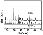
- Figure 7 is a comparison chart between the XRD spectrum of the positive active material core prepared in Example 1-1 and the standard XRD spectrum of lithium manganese phosphate (00-033-0804).
- Ranges disclosed herein are defined in terms of lower and upper limits. A given range is defined by selecting a lower limit and an upper limit that define the boundaries of the particular range. Ranges defined in this manner may be inclusive or exclusive of the endpoints, and may be arbitrarily combined, that is, any lower limit may be combined with any upper limit to form a range. For example, if ranges of 60-120 and 80-110 are listed for a particular parameter, understand that ranges of 60-110 and 80-120 are also expected. Furthermore, if the minimum range values 1 and 2 are listed, and if the maximum range values 3, 4, and 5 are listed, then the following ranges are all expected: 1-3, 1-4, 1-5, 2- 3, 2-4 and 2-5.
- the numerical range “a-b” represents an abbreviated representation of any combination of real numbers between a and b, where a and b are both real numbers.
- the numerical range “0-5" means that all real numbers between "0-5" have been listed in this article, and "0-5" is just an abbreviation of these numerical combinations.
- a certain parameter is an integer ⁇ 2
- the method includes steps (a) and (b), which means that the method may include steps (a) and (b) performed sequentially, or may include steps (b) and (a) performed sequentially.
- step (c) means that step (c) may be added to the method in any order.
- the method may include steps (a), (b) and (c). , may also include steps (a), (c) and (b), may also include steps (c), (a) and (b), etc.
- condition "A or B” is satisfied by any of the following conditions: A is true (or exists) and B is false (or does not exist); A is false (or does not exist) and B is true (or exists) ; Or both A and B are true (or exist).
- the median particle size Dv50 refers to the particle size corresponding to when the cumulative volume distribution percentage of the material reaches 50%.
- the median particle diameter Dv50 of the material can be determined using laser diffraction particle size analysis. For example, refer to the standard GB/T 19077-2016 and use a laser particle size analyzer (such as Malvern Master Size 3000) for measurement.
- aliphatic hydrocarbon group includes alkyl, alkenyl and alkynyl groups
- heteroaliphatic hydrocarbon group means that the aliphatic hydrocarbon group contains heteroatoms (such as N, O, S, etc.).
- heteroalkyl refers to an alkyl group containing heteroatoms (such as N, O, S, etc.), such as alkoxy, alkylthio, etc.
- coating layer refers to a material layer coated on the core.
- the material layer may completely or partially cover the core.
- the use of “coating layer” is only for convenience of description and is not intended to limit this article. invention.
- each coating layer can be completely covered or partially covered.
- source refers to a compound that is the source of a certain element.
- types of “source” include but are not limited to carbonates, sulfates, nitrates, elements, halides, and oxides. and hydroxides, etc.
- the inventor of the present application found in actual operations that manganese ions are relatively seriously eluted from the lithium manganese phosphate cathode active material during the deep charge and discharge process. Although there are attempts in the prior art to coat lithium manganese phosphate with lithium iron phosphate to reduce interface side reactions, this coating cannot prevent the migration of eluted manganese ions into the electrolyte. The eluted manganese ions are reduced to metallic manganese after migrating to the negative electrode. The metal manganese produced is equivalent to a "catalyst", which can catalyze the decomposition of the SEI film (solid electrolyte interphase, solid electrolyte interface film) on the surface of the negative electrode.
- Part of the by-products produced are gases, which can easily cause the battery to expand and affect the safety of the secondary battery. Performance, and the other part is deposited on the surface of the negative electrode, blocking the passage of lithium ions in and out of the negative electrode, causing the impedance of the secondary battery to increase and affecting the dynamic performance of the battery. In addition, in order to replenish the lost SEI film, the electrolyte and active lithium ions inside the battery are continuously consumed, which has an irreversible impact on the capacity retention rate of the secondary battery.
- the inventor found that for lithium manganese phosphate cathode active materials, problems such as severe manganese ion dissolution and high surface reactivity may be caused by the Ginger-Taylor effect of Mn 3+ after delithiation and the change in the size of the Li + channel.
- the inventor modified lithium manganese phosphate to obtain a cathode active material that can significantly reduce the dissolution of manganese ions and reduce the lattice change rate, and thus has good rate performance, cycle performance and safety performance.
- a first aspect of the present application provides a cathode active material with a core-shell structure, which includes a core and a shell covering the core, wherein,
- the core includes Li 1+x Mn 1-y A y P 1-z R z O 4 , x is -0.100 to 0.100, y is 0.001 to 0.500, z is 0.001 to 0.100, and the A is selected from Zn, Al , one or more of Na, K, Mg, Mo, W, Ti, V, Zr, Fe, Ni, Co, Ga, Sn, Sb, Nb and Ge, optionally Fe, Ti, V, Ni , one or more of Co and Mg, the R is selected from one or more of B, Si, N and S;
- the shell includes a first cladding layer covering the core, a second cladding layer covering the first cladding layer, and a third cladding layer covering the second cladding layer, wherein,
- the first coating layer includes pyrophosphate MP 2 O 7 and phosphate XPO 4 , and the M and X are each independently selected from Li, Fe, Ni, Mg, Co, Cu, Zn, Ti, Ag, Zr , one or more of Nb and Al;
- the second cladding layer includes carbon
- the third coating layer includes a polymer, and the polymer includes one or more selected from polysiloxane with a linear structure and polysiloxane with a cyclic structure.
- the above limitation on the numerical range of y is not only a limitation on the stoichiometric number of each element as A, but also on the stoichiometric number of each element as A.
- Limitation of the sum of stoichiometric numbers For example, when A is two or more elements A1, A2...An, the stoichiometric numbers y1, y2...yn of A1, A2...An each need to fall within the numerical range of y defined in this application, and y1 , y2...yn and the sum must also fall within this numerical range.
- the limitation on the numerical range of the R stoichiometric number in this application also has the above meaning.
- the lithium manganese phosphate cathode active material of the present application has a core-shell structure with three coating layers, in which the core includes Li 1+x Mn 1-y A y P 1-z R z O 4 .
- the element A doped in the manganese position of lithium manganese phosphate in the core helps to reduce the lattice change rate of lithium manganese phosphate during the lithium deintercalation process, improves the structural stability of the lithium manganese phosphate cathode active material, and greatly reduces the number of manganese ions. dissolution and reduce the oxygen activity on the particle surface.
- the element R doped at the phosphorus site helps change the ease of Mn-O bond length change, thereby reducing the lithium ion migration barrier, promoting lithium ion migration, and improving the rate performance of secondary batteries.
- the first coating layer of the cathode active material of the present application includes pyrophosphate and phosphate. Since the migration barrier of transition metals in pyrophosphate is high (>1eV), it can effectively inhibit the dissolution of transition metal ions. Phosphate has excellent ability to conduct lithium ions and can reduce the surface miscellaneous lithium content.
- the second coating layer of the cathode active material of the present application is a carbon-containing layer, which can effectively improve the conductive properties and desolvation ability of LiMnPO 4 .
- the "barrier" function of the second coating layer can further hinder the migration of manganese ions into the electrolyte and reduce the erosion of the cathode active material by the electrolyte.
- the third coating layer of the cathode active material of the present application includes one or more of polysiloxane with a linear structure and polysiloxane with a cyclic structure.
- the Si-O skeleton of polysiloxane can remove F-containing ions in the electrolyte and alleviate the erosion of acidic substances on the surface of the cathode active material; polysiloxane has a certain degree of hydrophobicity and can increase the contact between the electrolyte and the cathode plate. angle to further alleviate the erosion of the electrolyte on the surface of the positive active material.
- the third coating layer can also play a role in isolating the electrolyte and the cathode active material, so it can further hinder the migration of manganese ions into the electrolyte and reduce the erosion of the cathode active material by the electrolyte, thereby significantly improving cycle performance.
- this application can effectively suppress the dissolution of manganese ions during the process of deintercalating lithium, and at the same time promote the migration of lithium ions, thereby improving the rate performance and cycle performance of secondary batteries. performance and safety features.
- the core of the cathode active material in this application is basically consistent with the position of the main characteristic peak of LiMnPO 4 before doping, indicating that the doped lithium manganese phosphate cathode active material core has no impurity phase, and the improvement in secondary battery performance mainly comes from It is caused by elemental doping rather than impurity phases.
- the coating amount of the first coating layer is greater than 0% by weight and less than or equal to 7% by weight, optionally 4-5.6% by weight, based on the weight of the core.
- the coating amount of the first coating layer is within the above range, the elution of manganese ions can be further suppressed and the transport of lithium ions can be further promoted. And can effectively avoid the following situations: if the coating amount of the first coating layer is too small, the inhibitory effect of pyrophosphate on the dissolution of manganese ions may be insufficient, and the improvement of lithium ion transmission performance is not significant; if If the coating amount of the first coating layer is too large, the coating layer may be too thick, increase the battery impedance, and affect the dynamic performance of the secondary battery.
- the coating amount of the second coating layer is greater than 0% by weight and less than or equal to 6% by weight, optionally 3-5% by weight, based on the weight of the core.
- the carbon-containing layer as the second coating layer can function as a "barrier” to avoid direct contact between the positive active material and the electrolyte, thereby reducing the erosion of the positive active material by the electrolyte and improving the safety performance of the secondary battery at high temperatures.
- it has strong electrical conductivity, which can reduce the internal resistance of the battery, thereby improving the dynamic performance of the secondary battery.
- the carbon material has a low gram capacity, when the amount of the second coating layer is too large, the overall gram capacity of the cathode active material may be reduced. Therefore, when the coating amount of the second coating layer is within the above range, the kinetic performance and safety performance of the secondary battery can be further improved without sacrificing the gram capacity of the cathode active material.
- the coating amount of the third coating layer is greater than 0% by weight and less than or equal to 10% by weight, optionally greater than 0% by weight and less than or equal to 5% by weight, and further is greater than 0% by weight and less than or equal to 2% by weight, based on the weight of the core having the first cladding layer and the second cladding layer.
- the coating modification effect on the core is better, which can further suppress the dissolution of manganese ions and further promote the transport of lithium ions. And can effectively avoid the following situations: when the coating amount of the coating layer is too low, its effect in reducing the dissolution of manganese ions may not be obvious; when the coating amount of the coating layer is too high, the battery impedance may increase, which may affect the second battery life. Rate performance and cycle performance of secondary batteries.
- x is -0.100 to 0.100.
- x can be 0.006, 0.004, 0.003, 0.002, 0.001, 0, -0.001, -0.003, -0.004, -0.005, -0.006, -0.007, -0.008, -0.009, -0.100.
- y ranges from 0.001 to 0.500, for example, y can be 0.1, 0.2, 0.25, 0.3, 0.35, 0.4, 0.45.
- z ranges from 0.001 to 0.100, for example, z can be 0.001, 0.002, 0.003, 0.004, 0.005, 0.006, 0.007, 0.008, 0.009, 0.100.
- the ratio of y to 1-y is 1:10 to 10:1, optionally 1:4 to 1:1.
- y represents the sum of stoichiometric numbers of Mn-site doping elements.
- the ratio of z to 1-z is 1:9 to 1:999, optionally 1:499 to 1:249.
- y represents the sum of stoichiometric numbers of P-site doping elements.
- the A is selected from at least two of Fe, Ti, V, Ni, Co and Mg.
- Doping the manganese site in the lithium manganese phosphate cathode active material with two or more of the above elements at the same time is beneficial to enhancing the doping effect. On the one hand, it further reduces the lattice change rate, thereby inhibiting the dissolution of manganese ions and reducing the electrolyte and active lithium. On the other hand, the consumption of ions is also conducive to further reducing surface oxygen activity and reducing interface side reactions between the positive active material and the electrolyte, thereby improving the cycle performance and high-temperature storage performance of the secondary battery.
- the interplanar spacing of the phosphate of the first coating layer is 0.345-0.358 nm, and the angle between the crystal directions (111) is 24.25°-26.45°.
- the interplanar spacing of the pyrophosphate of the first coating layer is 0.293-0.326 nm, and the included angle of the crystal direction (111) is 26.41°-32.57°.
- the angle between the interplanar spacing and the crystal direction (111) of the phosphate and pyrophosphate in the first coating layer is within the above range, the impurity phase in the coating layer can be effectively avoided, thereby increasing the gram capacity of the cathode active material. , cycle performance and rate performance.
- the weight ratio of pyrophosphate and phosphate in the first coating layer is 1:3 to 3:1, optionally 1:3 to 1:1.
- the appropriate ratio of pyrophosphate and phosphate is conducive to giving full play to the synergistic effect of the two. It can not only effectively hinder the dissolution of manganese ions, but also effectively reduce the surface miscellaneous lithium content and reduce interface side reactions, thereby improving the rate performance of the secondary battery. , cycle performance and safety performance. And can effectively avoid the following situations: if there is too much pyrophosphate and too little phosphate, it may cause the battery impedance to increase; if there is too much phosphate and too little pyrophosphate, the effect of inhibiting the dissolution of manganese ions is not significant.
- the crystallinity of the pyrophosphate and phosphate salts each independently ranges from 10% to 100%, optionally from 50% to 100%.
- pyrophosphate and phosphate with a certain degree of crystallinity are beneficial to maintaining the structural stability of the first coating layer and reducing lattice defects.
- this is conducive to giving full play to the role of pyrophosphate in hindering the dissolution of manganese ions.
- it is also conducive to the phosphate reducing the surface miscellaneous lithium content and reducing the valence state of surface oxygen, thereby reducing the interface side reactions between the positive electrode active material and the electrolyte. , reduce the consumption of electrolyte, and improve the cycle performance and safety performance of secondary batteries.
- the crystallinity of pyrophosphate and phosphate can be adjusted, for example, by adjusting the process conditions of the sintering process, such as sintering temperature, sintering time, and the like.
- the crystallinity of pyrophosphate and phosphate can be measured by methods known in the art, such as by X-ray diffraction, density, infrared spectroscopy, differential scanning calorimetry, and nuclear magnetic resonance absorption methods.
- the polymer in the third coating layer includes at least one structural unit represented by Formula 1,
- R 1 and R 2 each independently represent H or at least one of the group consisting of the following functional groups: -COOH, -OH, -SH, -CN, -SCN, amino, phosphate group, carboxylate group, amide group, aldehyde group, sulfonyl group, polyether segment, C1 ⁇ C20 aliphatic hydrocarbon group, C1 ⁇ C20 halogenated aliphatic hydrocarbon group, C1 ⁇ C20 heteroaliphatic hydrocarbon group, C1 ⁇ C20 halogenated heteroaliphatic hydrocarbon group, C6 ⁇ C20 aromatic hydrocarbon group, C6 ⁇ C20 halogenated aromatic hydrocarbon group, C2 ⁇ C20 heteroaromatic hydrocarbon group, C2 ⁇ C20 halogenated heteroaromatic hydrocarbon group.
- R 1 and R 2 each independently represent H or at least one of the group consisting of the following functional groups: -OH, -SH, amino, phosphate group, polyether segment, C1 to C8 alkyl, C1 ⁇ C8 haloalkyl, C1 ⁇ C8 heteroalkyl, C1 ⁇ C8 haloheteroalkyl, C2 ⁇ C8 alkenyl, C2 ⁇ C8 haloalkenyl.
- These functional groups can complex manganese ions and reduce the dissolution of manganese ions. They can also remove F-containing ions in the electrolyte, further alleviate the erosion of the surface of the positive active material by acidic substances in the electrolyte, reduce the dissolution of manganese ions, and thus significantly improve the secondary Battery cycle performance.
- the linear-structured polysiloxane may further include an end-capping group.
- the end-capping group includes at least one of the following functional groups: polyether, C1-C8 alkyl, C1-C8 haloalkyl, C1-C8 heteroalkyl, C1-C8 haloheteroalkyl.
- the polysiloxanes with linear structures include, but are not limited to, polydimethylsiloxane, polydiethylsiloxane, polymethylethylsiloxane, and polymethylvinylsiloxane.
- polyphenylmethylsiloxane polymethylhydrogensiloxane, carboxyl functionalized polysiloxane, terminal epoxy polysiloxane, methoxy-terminated polydimethylsiloxane, polymethylsiloxane Chloropropylsiloxane, mercaptopropylpolysiloxane, aminoethylaminopropylpolydimethylsiloxane, terminal hydroxypropylpolysiloxane, terminal hydroxylpolydimethylsiloxane, terminal Based polyether polydimethylsiloxane, side-chain aminopropyl polysiloxane, aminopropyl-terminated polydimethylsiloxane, side-chain hydroxymethylpolysiloxane, side-chain hydroxypropyl polysiloxane
- siloxane side chain polyether grafted polydimethylsiloxane
- the linear structure polysiloxane includes hydroxyl-terminated polydimethylsiloxane, mercaptopropyl polysiloxane, aminoethylaminopropyl polydimethylsiloxane, side chain polysiloxane One or more of ether grafted polydimethylsiloxane and side chain phosphate grafted polydimethylsiloxane.
- the cyclic structure polysiloxane includes 1,3,5,7-octamethylcyclotetrasiloxane, 1,3,5,7-tetrahydro-1,3,5,7- Tetramethylcyclotetrasiloxane, cyclopentasiloxane, 2,4,6,8-tetramethylcyclotetrasiloxane, 2,4,6,8-tetramethyl-2, 4,6,8-tetravinylcyclotetrasiloxane, cyclic polymethylvinylsiloxane, hexadecylmethylcyclooctasiloxane, tetradecamethylcycloheptasiloxane, cyclic polydiethylene One or more methylsiloxanes.
- the polymer is selected from linear structured polysiloxanes.
- the electrons in the ring of polysiloxane with a cyclic structure have a certain degree of delocalization. Therefore, compared with polysiloxane with a linear structure, its Si-O skeleton has less affinity for electron-rich F-containing ions. Smaller, then the removal rate of F ions in the electrolyte is slightly lower, the effect of reducing the dissolution of manganese ions is slightly weaker, and the improvement effect on the cycle performance of the secondary battery is slightly less.
- the number average molecular weight of the polymer is below 300,000, for example, it can be 400 to 300,000, 400 to 200,000, 400 to 100,000, 400 to 80,000, 400 to 50,000, 400 to 20,000, 400 to 10,000, 1000 to 100000, 1000 to 50000, 1000 to 20000, 1000 to 10000.
- the number average molecular weight of a polymer can be determined by methods known in the art, such as gel permeation chromatography (GPC).
- the testing instrument can use PL-GPC220 high temperature gel permeation chromatograph.
- polymer can be either an oligomer or a polymer, which is not limited in this application.
- the cathode active material can also achieve both good dynamic performance and high temperature stability. And can effectively avoid the following situations: if the number average molecular weight of the polymer is too small, it may not have an obvious coating modification effect; if the number average molecular weight of the polymer is too large, its hydrophobicity may be strong, which may affect the secondary The kinetic performance of the battery may also lead to poor coating modification effects.
- the mass percentage of polar functional groups in the polysiloxane is ⁇ , 0 ⁇ 50%, optionally, 5% ⁇ 30%.
- “mass percentage of polar functional groups in polysiloxane” refers to the mass proportion of polar functional groups in R 1 , R 2 and end-capping groups in polysiloxane.
- ⁇ represents the mass fraction of these polar functional groups in polysiloxane; when the above polar functional groups are not directly connected to silicon atoms, ⁇ represents the sum of the polar functional groups and their The sum of the mass fractions of directly connected divalent to tetravalent methyl groups (such as -CH 2 , -CH-, -C-, etc.) in polysiloxane, where "divalent to tetravalent methyl" means the same as the polar
- divalent to tetravalent methyl groups such as -CH 2 , -CH-, -C-, etc.
- ⁇ refers to the mass percentage of -CF 3 , excluding the ethylene group; taking polymethylchloropropylsiloxane as an example, ⁇ is Refers to the mass percentage of -CH 2 Cl, excluding the ethylene group; taking hydroxypropyl-terminated polydimethylsiloxane as an example, ⁇ refers to the mass percentage of -CH 2 OH.
- the mass percentage of polar functional groups in polysiloxane can be determined by methods known in the art, such as titration (such as acid-base titration, redox titration, precipitation titration), infrared spectroscopy, and nuclear magnetic resonance. Determined by spectroscopy.
- the Li/Mn anti-site defect concentration of the cathode active material is 4% or less, optionally 2% or less.
- the Li/Mn antisite defect refers to the interchange of positions of Li + and Mn 2+ in the LiMnPO 4 lattice.
- the Li/Mn anti-site defect concentration refers to the percentage of Li + exchanged with Mn 2+ in the positive active material to the total amount of Li + . Since the Li + transport channel is a one-dimensional channel, Mn 2+ is difficult to migrate in the Li + transport channel. Therefore, the anti-site defective Mn 2+ will hinder the transport of Li + .
- the cathode active material of the present application by controlling the Li/Mn anti-site defect concentration at a low level, the gram capacity and rate performance of the cathode active material can be improved.
- the anti-site defect concentration can be measured in accordance with JIS K 0131-1996, for example.
- the lattice change rate of the cathode active material is 6% or less, optionally 4% or less.
- the lithium deintercalation process of LiMnPO 4 is a two-phase reaction.
- the interface stress of the two phases is determined by the lattice change rate. The smaller the lattice change rate, the smaller the interface stress and the easier Li + transport. Therefore, reducing the lattice change rate of the core will be beneficial to enhancing the Li + transport capability, thereby improving the rate performance of secondary batteries.
- the average discharge voltage of the cathode active material is more than 3.5V, and the discharge capacity is more than 140mAh/g; optionally, the average discharge voltage is more than 3.6V, and the discharge capacity is more than 145mAh. /g or above.
- the average discharge voltage of undoped LiMnPO 4 is above 4.0V, its discharge gram capacity is low, usually less than 120mAh/g. Therefore, the energy density of the secondary battery is low; the lattice change rate is adjusted by doping , which can greatly increase its discharge capacity and significantly increase the overall energy density of the secondary battery while the average discharge voltage drops slightly.
- the surface oxygen valence state of the cathode active material is -1.88 or less, optionally -1.98 to -1.88.
- the higher the valence state of oxygen in the compound the stronger its ability to obtain electrons, that is, the stronger its oxidizing property.
- the reactivity on the surface of the cathode active material can be reduced, and the interface side reactions between the cathode active material and the electrolyte can be reduced, thereby improving Cycle performance and high temperature storage performance of secondary batteries.
- the compacted density of the positive active material at 3 tons (T) is above 2.0 g/cm 3 , optionally above 2.2 g/cm 3 .
- the compacted density of the positive active material that is, the greater the weight of the active material per unit volume, the more beneficial it will be to increase the volume energy density of the secondary battery.
- the compacted density can be measured according to GB/T 24533-2009, for example.
- the second aspect of the application provides a preparation method of the cathode active material of the first aspect of the application, which includes the following steps:
- the core includes Li 1+x Mn 1-y A y P 1-z R z O 4 , wherein x is -0.100 to 0.100, y is 0.001 to 0.500, and z is 0.001 to 0.100,
- the A is selected from one or more of Zn, Al, Na, K, Mg, Mo, W, Ti, V, Zr, Fe, Ni, Co, Ga, Sn, Sb, Nb and Ge, optional is one or more of Fe, Ti, V, Ni, Co and Mg, and the R is selected from one or more of B, Si, N and S;
- Coating step Provide MP 2 O 7 powder and an XPO 4 suspension containing a carbon source, add the core material and MP 2 O 7 powder to the XPO 4 suspension containing a carbon source, and mix. Sintering obtains a core with a first coating layer and a second coating layer, and dry-coating or wet-coating the obtained core with a first coating layer and a second coating layer with a polymer to obtain a positive electrode Active material, wherein the polymer includes one or more selected from polysiloxane with linear structure and polysiloxane with cyclic structure, and M and X are each independently selected from Li, Fe , one or more of Ni, Mg, Co, Cu, Zn, Ti, Ag, Zr, Nb and Al;
- the positive active material has a core-shell structure, which includes an inner core and a shell covering the inner core.
- the shell includes a first coating layer covering the inner core, and a first coating layer covering the inner core. and a third coating layer covering the second coating layer.
- the first coating layer includes pyrophosphate MP 2 O 7 and phosphate XPO 4 .
- the second coating layer includes carbon, and the third coating layer includes a polymer, and the polymer includes one or more selected from the group consisting of polysiloxane with a linear structure and polysiloxane with a cyclic structure.
- the step of providing core material includes the following steps:
- Step (1) Mix and stir the source of manganese, the source of element A and the acid in a container to obtain manganese salt particles doped with element A;
- Step (2) Mix the manganese salt particles doped with element A with a source of lithium, a source of phosphorus and a source of element R in a solvent to obtain a slurry, and then sinter it under the protection of an inert gas atmosphere to obtain doping.
- Lithium manganese phosphate doped with element A and element R wherein the lithium manganese phosphate doped with element A and element R is Li 1+x Mn 1-y A y P 1-z R z O 4 , x is - 0.100 to 0.100, y is 0.001 to 0.500, z is 0.001 to 0.100, and the A is selected from Zn, Al, Na, K, Mg, Mo, W, Ti, V, Zr, Fe, Ni, Co, Ga, Sn , one or more of Sb, Nb and Ge, optionally one or more of Fe, Ti, V, Ni, Co and Mg, the R is selected from B, Si, N and S one or more.
- step (1) is performed at a temperature of 20-120°C, optionally 25-80°C.
- the stirring in step (1) is performed at 500-700 rpm for 60-420 minutes, optionally 120-360 minutes.
- the doping elements can be evenly distributed, reduce lattice defects, inhibit the dissolution of manganese ions, and reduce the interface side reactions between the cathode active material and the electrolyte, thereby improving the cathode activity.
- the source of a certain element may include one or more of the elements, sulfates, halides, nitrates, organic acid salts, oxides or hydroxides, where It is this source that can achieve the purpose of the preparation method of the present application.
- the source of element A is selected from one or more of elements, sulfates, halides, nitrates, organic acid salts, oxides or hydroxides of element A; and/or, the element The source of R is selected from one or more elements, sulfates, halides, nitrates, organic acid salts, oxides or hydroxides of element R, and inorganic acids of element R.
- the source of manganese in this application is one or more selected from the group consisting of elemental manganese, manganese dioxide, manganese phosphate, manganese oxalate, and manganese carbonate.
- element A is iron
- the source of iron is one or more selected from ferrous carbonate, ferric hydroxide, and ferrous sulfate.
- the acid is selected from one or more of hydrochloric acid, sulfuric acid, nitric acid, phosphoric acid, organic acids such as oxalic acid, etc., optionally oxalic acid.
- the acid is a dilute acid with a concentration of 60% by weight or less.
- the inorganic acid of element R is selected from one or more of phosphoric acid, nitric acid, boric acid, silicic acid, and orthosilicic acid.
- the source of lithium in this application is one or more selected from the group consisting of lithium carbonate, lithium hydroxide, lithium phosphate, and lithium dihydrogen phosphate.
- the source of phosphorus in this application is one or more selected from the group consisting of diammonium hydrogen phosphate, ammonium dihydrogen phosphate, ammonium phosphate and phosphoric acid.
- the source of carbon in this application is an organic carbon source, and the organic carbon source is selected from one of starch, sucrose, glucose, polyvinyl alcohol, polyethylene glycol, and citric acid. or more.
- the solvent used in the preparation method described in this application is a solvent commonly used in the art.
- the solvents in the preparation method of the present application can be independently selected from at least one of ethanol and water (such as deionized water).
- the pH of the solution is controlled to be 4-6. It should be noted that in this application, the pH of the resulting mixture can be adjusted by methods commonly used in the art, for example, by adding acid or alkali.
- step (2) the molar ratio of the manganese salt particles doped with element A to the source of lithium and the source of phosphorus is 1:(0.5-2.1):(0.5 -2.1).
- the sintering conditions are: sintering at 600-800°C for 4-10 hours under an inert gas or a mixed atmosphere of inert gas and hydrogen.
- the crystallinity of the material after sintering is higher, which can improve the gram capacity and rate performance of the cathode active material.
- the mixture of inert gas and hydrogen is nitrogen (70-90 volume%) + hydrogen (10-30 volume%).
- the MP 2 O 7 powder is a commercially available product, or alternatively, the MP 2 O 7 powder is prepared by adding a source of element M and a source of phosphorus to In the solvent, a mixture is obtained, adjust the pH of the mixture to 4-6, stir and fully react, and then obtain it by drying and sintering, wherein M is selected from Li, Fe, Ni, Mg, Co, Cu, Zn, Ti, Ag, One or more of Zr, Nb and Al.
- the drying step is drying at 100-300°C, optionally 150-200°C for 4-8 hours.
- the sintering step is sintering under an inert gas atmosphere at 500-800°C, optionally 650-800°C, for 4-10 hours .
- the XPO suspension comprising a source of carbon is commercially available, or alternatively, is prepared by combining a source of lithium, a source of X, phosphorus The source and the carbon source are mixed evenly in the solvent, and then the reaction mixture is heated to 60-120°C and maintained for 2-8 hours to obtain an XPO 4 suspension containing the carbon source.
- the pH of the mixture is adjusted to 4-6.
- the A and R elements doped lithium manganese phosphate (core), MP 2 O 7 powder and XPO 4 suspension containing the source of carbon are The mass ratio is 1:(0.001-0.05):(0.001-0.05).
- the sintering temperature when obtaining the core having the first coating layer and the second coating layer in the coating step is 500-800°C, and the sintering time is 4-10 hours.
- dry coating to prepare the cathode active material in the coating step may be to mix the core with the first coating layer and the second coating layer and the polymer evenly using a mixer to form a mixed powder. , and then sintered in a sintering furnace in a nitrogen or inert gas atmosphere. Sintering can be carried out at a temperature range of 200-300°C for 4-10 hours. Optionally sintered at about 200°C, about 250°C, or about 300°C for about 4 hours, about 6 hours, about 8 hours, or about 10 hours. Optionally, the sintering temperature and sintering time may be within any range of any of the above values.
- the sintering temperature and time within the above range, the following situations can be effectively avoided: when the sintering temperature is too low or the sintering time is too short, the bonding between the third cladding layer and the second cladding layer may not be strong enough; sintering temperature When the temperature is too high or the sintering time is too long, the third coating layer may be carbonized and cannot remove F ions from the electrolyte.
- wet coating is used to prepare the cathode active material by dissolving the polymer in a solvent to form a coating liquid, and then adding a first coating layer and a second coating layer thereto.
- the inner core is stirred evenly to form a mixed slurry, and then the mixed slurry is placed in a wet bag machine and dried while stirring in a nitrogen or inert gas atmosphere.
- the median particle diameter Dv50 of the primary particles of the triple-coated lithium manganese phosphate cathode active material of the present application is 50-2000 nm.
- a third aspect of the present application provides a positive electrode sheet, which includes a positive electrode current collector and a positive electrode film layer disposed on at least one surface of the positive electrode current collector.
- the positive electrode film layer includes the positive electrode active material of the first aspect of the present application or is formed by the positive electrode active material of the present application.
- the cathode active material prepared by the method of the second aspect is applied, and the content of the cathode active material in the cathode film layer is more than 10% by weight, based on the total weight of the cathode film layer.
- the positive electrode current collector has two surfaces opposite in its thickness direction, and the positive electrode film layer is disposed on any one or both of the two opposite surfaces of the positive electrode current collector.
- the content of the cathode active material in the cathode film layer is 90-99.5% by weight, based on the total weight of the cathode film layer.
- the content of the cathode active material is within the above range, it is beneficial to give full play to the advantages of the cathode active material of the present application.
- the cathode film layer does not exclude other cathode active materials other than the cathode active material of the first aspect of the application or the cathode active material prepared by the method of the second aspect of the application.
- the cathode film layer may also include lithium transition metal oxide. At least one of its modified compounds.
- the other cathode active materials may include lithium cobalt oxide, lithium nickel oxide, lithium manganese oxide, lithium nickel cobalt oxide, lithium manganese cobalt oxide, lithium nickel manganese oxide, lithium nickel cobalt manganese oxide , at least one of lithium nickel cobalt aluminum oxide and its modified compounds.
- the positive electrode film layer optionally further includes a positive electrode conductive agent.
- a positive electrode conductive agent includes superconducting carbon, conductive graphite, acetylene black, carbon black, Ketjen black, carbon dots, carbon nanotubes, and graphene. , at least one of carbon nanofibers.
- the positive electrode film layer optionally further includes a positive electrode binder.
- a positive electrode binder may include polyvinylidene fluoride (PVDF), polytetrafluoroethylene (PTFE), vinylidene fluoride-tetrafluoroethylene -At least one of propylene terpolymer, vinylidene fluoride-hexafluoropropylene-tetrafluoroethylene terpolymer, tetrafluoroethylene-hexafluoropropylene copolymer, and fluorine-containing acrylate resin.
- the positive electrode current collector may be a metal foil or a composite current collector.
- a metal foil aluminum foil can be used.
- the composite current collector may include a polymer material base layer and a metal material layer formed on at least one surface of the polymer material base layer.
- the metal material may be selected from at least one of aluminum, aluminum alloy, nickel, nickel alloy, titanium, titanium alloy, silver, and silver alloy.
- the polymer material base layer can be selected from the group consisting of polypropylene (PP), polyethylene terephthalate (PET), polybutylene terephthalate (PBT), polystyrene (PS), poly Ethylene (PE), etc.
- the solid-liquid contact angle between the positive electrode film layer and the non-aqueous organic solvent is between 3° and 90°, optionally between 3° and 60°, further between 10° and 10°. between 30°.
- the contact angle is within a suitable range, the secondary battery can achieve both high energy density and good rate performance, cycle performance and safety performance. And can effectively avoid the following situations: if the contact angle is too small, the polymer may not be able to perform a good coating modification effect, and its effect on improving cycle performance may not be obvious; if the contact angle is too large, the positive electrode film may be damaged The wettability of the electrolyte becomes poor, which affects the rate performance and cycle performance of the secondary battery.
- the solid-liquid contact angle between the positive electrode film layer and the non-aqueous organic solvent is a well-known meaning in the art, and can be tested using methods known in the art. For example, it can be measured with reference to GBT 30693-2014.
- An exemplary test method includes the following steps: at room temperature, droplets of non-aqueous organic solvent are placed on the surface of the positive electrode piece, and the contact angle within 60 seconds is measured using a contact angle measuring instrument.
- the testing instrument can be the LSA 200 optical contact angle measuring instrument from the German LAUDA Scientific company.
- the non-aqueous organic solvent may be a non-aqueous organic solvent that is well known in the art and is used in non-aqueous electrolyte solutions for secondary batteries. Alternatively, the non-aqueous organic solvent may be ethylene carbonate (EC).
- the porosity of the positive electrode film layer is 15% to 50%, optionally 15% to 30%.
- the secondary battery can achieve both high energy density and good rate performance, cycle performance and safety performance. And can effectively avoid the following situations: when the porosity is too small, the electrolyte wettability of the positive electrode film layer may become poor, affecting the rate performance and cycle performance of the secondary battery; when the porosity is too large, it may affect the secondary battery overall energy density.
- the porosity of the positive electrode film layer has a well-known meaning in the art, and can be tested using methods known in the art. For example, it can be measured with reference to GB/T 24586-2009.
- the positive electrode film layer is usually formed by coating the positive electrode slurry on the positive electrode current collector, drying, and cold pressing.
- the positive electrode slurry is usually formed by dispersing the positive electrode active material, optional conductive agent, optional binder and any other components in a solvent and stirring evenly.
- the solvent may be N-methylpyrrolidone (NMP), but is not limited thereto.
- each positive electrode film layer (such as contact angle, porosity, etc.) given in this application refer to the parameters of the positive electrode film layer on one side of the positive electrode current collector.
- the positive electrode film layer is disposed on both sides of the positive electrode current collector, if the parameters of the positive electrode film layer on either side meet the requirements of this application, it is deemed to fall within the protection scope of this application.
- the above-mentioned parameter tests for the positive electrode film layer can be performed by sampling and testing during the preparation process of the electrode sheet or battery, or by sampling and testing from the prepared battery.
- the sampling can be carried out according to the following steps: discharge the battery (for safety reasons, the battery is generally in a fully discharged state); disassemble the battery and take out the positive electrode sheet, use dimethyl carbonate (DMC) to soak the positive electrode sheet for a certain period of time (for example, 2-10 hours); then take out the positive electrode sheet and dry it at a certain temperature and time (for example, 60°C, 4 hours), and dry Finally, the positive electrode piece is taken out. At this time, samples can be taken from the dried positive electrode piece to test various parameters related to the positive electrode film layer mentioned above in this application.
- DMC dimethyl carbonate
- the fourth aspect of the present application provides a secondary battery, which includes the positive electrode sheet of the third aspect of the present application.
- Secondary batteries also known as rechargeable batteries or storage batteries, refer to batteries that can be recharged to activate active materials and continue to be used after the battery is discharged.
- a secondary battery includes an electrode assembly and an electrolyte.
- the electrode assembly includes a positive electrode plate, a negative electrode plate and a separator.
- the isolation film is placed between the positive electrode piece and the negative electrode piece. It mainly prevents the positive and negative electrodes from short-circuiting and allows active ions to pass through.
- the electrolyte plays a role in conducting active ions between the positive electrode piece and the negative electrode piece.
- the positive electrode sheet used in the secondary battery of the present application is the positive electrode sheet described in any embodiment of the third aspect of the present application.
- the negative electrode sheet includes a negative electrode current collector and a negative electrode film layer disposed on at least one surface of the negative electrode current collector and including a negative electrode active material.
- the negative electrode current collector has two surfaces opposite in its thickness direction, and the negative electrode film layer is disposed on any one or both of the two opposite surfaces of the negative electrode current collector.
- the negative active material may be a negative active material known in the art for secondary batteries.
- the negative active material includes but is not limited to at least one of natural graphite, artificial graphite, soft carbon, hard carbon, silicon-based materials, tin-based materials, and lithium titanate.
- the silicon-based material may include at least one of elemental silicon, silicon oxide, silicon-carbon composite, silicon-nitride composite, and silicon alloy material.
- the tin-based material may include at least one of elemental tin, tin oxide, and tin alloy materials.
- the present application is not limited to these materials, and other conventionally known materials that can be used as negative electrode active materials for secondary batteries can also be used. Only one type of these negative electrode active materials may be used alone, or two or more types may be used in combination.
- the negative electrode film layer optionally further includes a negative electrode conductive agent.
- a negative electrode conductive agent may include superconducting carbon, conductive graphite, acetylene black, carbon black, Ketjen black, carbon dots, carbon nanotubes, graphite At least one of alkenes and carbon nanofibers.
- the negative electrode film layer optionally further includes a negative electrode binder.
- a negative electrode binder may include styrene-butadiene rubber (SBR), water-soluble unsaturated resin SR-1B, water-based acrylic resin (for example, At least one of polyacrylic acid PAA, polymethacrylic acid PMAA, polyacrylic acid sodium PAAS), polyacrylamide (PAM), polyvinyl alcohol (PVA), sodium alginate (SA), carboxymethyl chitosan (CMCS) kind.
- SBR styrene-butadiene rubber
- SR-1B water-soluble unsaturated resin
- acrylic resin for example, At least one of polyacrylic acid PAA, polymethacrylic acid PMAA, polyacrylic acid sodium PAAS), polyacrylamide (PAM), polyvinyl alcohol (PVA), sodium alginate (SA), carboxymethyl chitosan (CMCS) kind.
- the negative electrode film layer optionally further includes other additives.
- other auxiliaries may include thickeners, such as sodium carboxymethylcellulose (CMC), PTC thermistor materials, and the like.
- the negative electrode current collector may be a metal foil or a composite current collector.
- the metal foil copper foil can be used.
- the composite current collector may include a polymer material base layer and a metal material layer formed on at least one surface of the polymer material base layer.
- the metal material may be selected from at least one of copper, copper alloy, nickel, nickel alloy, titanium, titanium alloy, silver, and silver alloy.
- the polymer material base layer can be selected from the group consisting of polypropylene (PP), polyethylene terephthalate (PET), polybutylene terephthalate (PBT), polystyrene (PS), poly Ethylene (PE), etc.
- the negative electrode film layer is usually formed by coating the negative electrode slurry on the negative electrode current collector, drying, and cold pressing.
- the negative electrode slurry is usually formed by dispersing the negative electrode active material, optional conductive agent, optional binder, and other optional additives in a solvent and stirring evenly.
- the solvent may be N-methylpyrrolidone (NMP) or deionized water, but is not limited thereto.
- the negative electrode plate does not exclude other additional functional layers in addition to the negative electrode film layer.
- the negative electrode sheet described in the present application further includes a conductive undercoat layer (for example, made of Conductive agent and adhesive).
- the negative electrode sheet described in this application further includes a protective layer covering the surface of the negative electrode film layer.
- the electrolyte may be selected from at least one of a solid electrolyte and a liquid electrolyte (ie, electrolyte).
- the electrolyte is an electrolyte solution that includes an electrolyte salt and a solvent.
- the electrolyte salt may include lithium hexafluorophosphate (LiPF 6 ), lithium tetrafluoroborate (LiBF 4 ), lithium perchlorate (LiClO 4 ), lithium hexafluoroarsenate (LiAsF 6 ), bis Lithium fluorosulfonyl imide (LiFSI), lithium bistrifluoromethanesulfonyl imide (LiTFSI), lithium trifluoromethanesulfonate (LiTFS), lithium difluoromethanesulfonyl borate (LiDFOB), lithium dioxalatoborate (LiBOB), At least one of lithium difluorophosphate (LiPO 2 F 2 ), lithium difluorodioxalate phosphate (LiDFOP), and lithium tetrafluorooxalate
- the solvent may include ethylene carbonate (EC), propylene carbonate (PC), ethyl methyl carbonate (EMC), diethyl carbonate (DEC), dimethyl carbonate ( DMC), dipropyl carbonate (DPC), methylpropyl carbonate (MPC), ethylpropyl carbonate (EPC), butylene carbonate (BC), fluoroethylene carbonate (FEC), methyl formate (MF) , methyl acetate (MA), ethyl acetate (EA), propyl acetate (PA), methyl propionate (MP), ethyl propionate (EP), propyl propionate (PP), methyl butyrate At least one of (MB), ethyl butyrate (EB), 1,4-butyrolactone (GBL), sulfolane (SF), dimethyl sulfone (MSM), methyl ethyl
- additives are optionally included in the electrolyte.
- the additives may include negative electrode film-forming additives, positive electrode film-forming additives, and may also include additives that can improve certain properties of the battery, such as additives that improve battery overcharge performance, additives that improve battery high-temperature performance, and additives that improve battery performance. Additives for low temperature power performance, etc.
- Secondary batteries using electrolytes and some secondary batteries using solid electrolytes also include a separator.
- the isolation film is disposed between the positive electrode piece and the negative electrode piece, and mainly functions to prevent the positive and negative electrodes from short-circuiting, and at the same time, allows active ions to pass through.
- the material of the isolation membrane may include at least one of glass fiber, non-woven fabric, polyethylene, polypropylene and polyvinylidene fluoride.
- the isolation film may be a single-layer film or a multi-layer composite film. When the isolation film is a multi-layer composite film, the materials of each layer may be the same or different.
- the positive electrode piece, the isolation film and the negative electrode piece can be made into an electrode assembly through a winding process or a lamination process.
- the secondary battery may include an outer packaging.
- the outer packaging can be used to package the above-mentioned electrode assembly and electrolyte.
- the outer packaging of the secondary battery may be a hard shell, such as a hard plastic shell, an aluminum shell, a steel shell, etc.
- the outer packaging of the secondary battery may also be a soft bag, such as a bag-type soft bag.
- the soft bag may be made of plastic, such as at least one of polypropylene (PP), polybutylene terephthalate (PBT), polybutylene succinate (PBS), and the like.
- This application has no particular limitation on the shape of the secondary battery, which can be cylindrical, square or any other shape. As shown in FIG. 1 , a square-structured secondary battery 5 is shown as an example.
- the outer package may include a housing 51 and a cover 53 .
- the housing 51 may include a bottom plate and side plates connected to the bottom plate, and the bottom plate and the side plates enclose to form a receiving cavity.
- the housing 51 has an opening communicating with the accommodation cavity, and the cover plate 53 is used to cover the opening to close the accommodation cavity.
- the positive electrode piece, the negative electrode piece and the isolation film can be formed into the electrode assembly 52 through a winding process or a lamination process.
- the electrode assembly 52 is packaged in the containing cavity.
- the electrolyte soaks into the electrode assembly 52 .
- the number of electrode assemblies 52 contained in the secondary battery 5 can be one or several, and can be adjusted according to needs.
- the positive electrode sheet, the separator, the negative electrode sheet, and the electrolyte may be assembled to form a secondary battery.
- the positive electrode sheet, isolation film, and negative electrode sheet can be formed into an electrode assembly through a winding process or a lamination process.
- the electrode assembly is placed in an outer package, dried, and then injected with electrolyte. After vacuum packaging, standing, and Through processes such as formation and shaping, secondary batteries are obtained.
- the secondary batteries according to the present application can be assembled into a battery module.
- the number of secondary batteries contained in the battery module can be multiple, and the specific number can be adjusted according to the application and capacity of the battery module.
- FIG. 3 is a schematic diagram of the battery module 4 as an example.
- a plurality of secondary batteries 5 may be arranged in sequence along the length direction of the battery module 4 .
- the plurality of secondary batteries 5 can be fixed by fasteners.
- the battery module 4 may further include a housing having a receiving space in which a plurality of secondary batteries 5 are received.
- the above-mentioned battery modules can also be assembled into a battery pack, and the number of battery modules contained in the battery pack can be adjusted according to the application and capacity of the battery pack.
- the battery pack 1 may include a battery box and a plurality of battery modules 4 arranged in the battery box.
- the battery box includes an upper box 2 and a lower box 3 .
- the upper box 2 is used to cover the lower box 3 and form a closed space for accommodating the battery module 4 .
- Multiple battery modules 4 can be arranged in the battery box in any manner.
- a fifth aspect of the present application provides an electrical device, which includes at least one of a secondary battery, a battery module, or a battery pack of the present application.
- the secondary battery, battery module or battery pack may be used as a power source for the electrical device or as an energy storage unit for the electrical device.
- the electrical device may be, but is not limited to, mobile devices (such as mobile phones, laptops, etc.), electric vehicles (such as pure electric vehicles, hybrid electric vehicles, plug-in hybrid electric vehicles, electric bicycles, electric scooters, electric Golf carts, electric trucks, etc.), electric trains, ships and satellites, energy storage systems, etc.
- the power-consuming device can select a secondary battery, a battery module or a battery pack according to its usage requirements.
- FIG. 6 is a schematic diagram of an electrical device as an example.
- the electric device is a pure electric vehicle, a hybrid electric vehicle, a plug-in hybrid electric vehicle, etc.
- battery packs or battery modules can be used.
- the power-consuming device may be a mobile phone, a tablet computer, a laptop computer, etc.
- the electrical device is usually required to be light and thin, and secondary batteries can be used as power sources.
- the reaction kettle was heated to 80°C and stirred at a rotation speed of 600 rpm for 6 hours until the reaction was terminated (no bubbles were generated) to obtain a manganese oxalate suspension co-doped with Fe, Co, V and S.
- the suspension was then filtered, and the filter cake was dried at 120° C. and then ground to obtain Fe, Co and V co-doped manganese oxalate dihydrate particles with a median particle size Dv50 of 100 nm.
- Preparation of Fe, Co, V and S co-doped lithium manganese phosphate combine the manganese oxalate dihydrate particles obtained in the previous step (1793.4g), 369.0g lithium carbonate (calculated as Li 2 CO 3 , the same below), 1.6g Dilute sulfuric acid with a concentration of 60% (calculated as 60% H 2 SO 4 , the same below) and 1148.9g ammonium dihydrogen phosphate (calculated as NH 4 H 2 PO 4 , the same below) were added to 20 liters of deionized water, and the mixture was Stir for 10 hours to mix evenly and obtain a slurry.
- lithium iron pyrophosphate powder Dissolve 4.77g lithium carbonate, 7.47g ferrous carbonate, 14.84g ammonium dihydrogen phosphate and 1.3g oxalic acid dihydrate in 50mL deionized water. The pH of the mixture was 5, and the reaction mixture was stirred for 2 hours to fully react. The reacted solution was then heated to 80°C and maintained at this temperature for 4 hours to obtain a suspension containing Li 2 FeP 2 O 7. The suspension was filtered, washed with deionized water, and dried at 120°C for 4 hours to obtain powder. The powder was sintered at 650° C. in a nitrogen atmosphere for 8 hours, and then naturally cooled to room temperature and then ground to obtain Li 2 FeP 2 O 7 powder.
- lithium iron phosphate suspension Dissolve 11.1g lithium carbonate, 34.8g ferrous carbonate, 34.5g ammonium dihydrogen phosphate, 1.3g oxalic acid dihydrate and 74.6g sucrose (calculated as C 12 H 22 O 11 , the same below) In 150 mL of deionized water, a mixture was obtained, and then stirred for 6 hours to allow the above mixture to fully react. The reacted solution was then heated to 120°C and maintained at this temperature for 6 hours to obtain a suspension containing LiFePO4 .
- the mass percentage of the polar functional group (i.e. -OH) of the hydroxyl-terminated polydimethylsiloxane is 3.4%
- the number average molecular weight is 1000
- the coating amount is 1% by weight. Based on the first coating layer and the weight of the core of the second cladding layer.
- the three-layer coated lithium manganese phosphate cathode active material prepared above, the conductive agent acetylene black, and the binder polyvinylidene fluoride (PVDF) were added to N-methylpyrrolidone (NMP) in a weight ratio of 92:2.5:5.5 ), stir and mix evenly to obtain positive electrode slurry. Then, the positive electrode slurry is evenly coated on the aluminum foil at a density of 0.280g/ 1540.25mm2 , dried, cold pressed, and cut to obtain the positive electrode piece.
- the negative electrode slurry is evenly coated on the negative electrode current collector copper foil at a density of 0.117g/1540.25mm 2 , and then dried, cold pressed, and cut to obtain negative electrode pieces.
- a commercially available PP-PE copolymer microporous film with a thickness of 20 ⁇ m and an average pore diameter of 80 nm was used.
- the positive electrode piece, isolation film, and negative electrode piece obtained above are stacked in order, so that the isolation film is between the positive and negative electrodes to play an isolation role, and the electrode assembly is obtained by winding.
- the electrode assembly is placed in an outer package, and the above-mentioned electrolyte is injected and packaged to obtain a full battery (hereinafter also referred to as "full battery").
- the three-layer coated lithium manganese phosphate cathode active material prepared above, PVDF, and acetylene black were added to NMP in a weight ratio of 90:5:5, and stirred in a drying room to form a slurry.
- the above slurry is coated on aluminum foil, dried and cold pressed to form a positive electrode sheet.
- the coating amount is 0.2g/cm 2 and the compacted density is 2.0g/cm 3 .
- Lithium sheets were used as the negative electrode, and a solution of 1 mol/L LiPF 6 in ethylene carbonate (EC) + diethyl carbonate (DEC) + dimethyl carbonate (DMC) with a volume ratio of 1:1:1 was used as the electrolyte.
- liquid, together with the positive electrode sheet prepared above, are assembled into a button battery (hereinafter also referred to as a "button battery") in a buckle box.
- the amount of sucrose used in Examples 1-2 to 1-6 is 37.3g, and in Examples 1-2 to 1-6 During the coating process, the dosage of hydroxyl-terminated polydimethylsiloxane was adjusted to 1% of the weight of the obtained core with the first coating layer and the second coating layer. Other conditions were the same as in Example 1-1. same.
- the amounts of sucrose removed are 74.6g, 149.1g, 186.4g and 223.7g respectively so that the corresponding coating amounts of the carbon layer as the second coating layer are 31.4g, 62.9g, 78.6g and 94.3g respectively, and in the package During the coating process, the dosage of hydroxyl-terminated polydimethylsiloxane is adjusted to other than 1% of the weight of the core obtained with the first coating layer and the second coating layer, Examples 1-7 to 1-10 The conditions are the same as those in Examples 1-3.
- the amounts of various raw materials are adjusted accordingly according to the coating amounts shown in Table 1 so that the amounts of Li 2 FeP 2 O 7 /LiFePO 4 are 23.6g/39.3g respectively. , 31.4g/31.4g, 39.3g/23.6g and 47.2g/15.7g, and during the coating process, the dosage of hydroxyl-terminated polydimethylsiloxane is adjusted to obtain the first coating layer and the third coating layer.
- the conditions of Examples 1-11 to 1-14 were the same as Example 1-7 except that the second coating layer accounted for 1% of the weight of the core.
- Examples 1-15 were the same as Examples 1-14 except for 1% by weight of the core of the cladding layer and the second cladding layer.
- Examples 1-16 used 466.4g of nickel carbonate, 5.0g of zinc carbonate and 7.2g of titanium sulfate instead of ferrous carbonate in the preparation process of the co-doped lithium manganese phosphate core.
- 455.2g of ferrous carbonate and 8.5g of vanadium dichloride were used in the preparation process of the co-doped lithium manganese phosphate core.
- Examples 1-16 to 1-18 the amount of hydroxyl-terminated polydimethylsiloxane was adjusted during the coating process to obtain the first
- the conditions of Examples 1-16 to 1-18 were the same as Example 1-7 except for 1% by weight of the core of the cladding layer and the second cladding layer.
- Examples 1-19 used 369.4g of lithium carbonate and 1.05g of 60% concentrated dilute nitric acid instead of dilute sulfuric acid in the preparation process of the co-doped lithium manganese phosphate core.
- 369.7g of lithium carbonate and 0.78g of silicic acid were used instead of dilute sulfuric acid, and in Examples 1-19 to 1-20, hydroxyl-terminated polydimethylsilane was used during the coating process.
- the conditions of Examples 1-19 to 1-20 were the same as those of Example 1-18 except that the amount of oxane was adjusted to 1% by weight of the obtained core having the first coating layer and the second coating layer.
- Examples 1-21 632.0g manganese carbonate, 463.30g ferrous carbonate, 30.5g vanadium dichloride, 21.0g magnesium carbonate and 0.78g silicic acid were used in the preparation process of the co-doped lithium manganese phosphate core. ;
- Example 1-22 uses 746.9g manganese carbonate, 289.6g ferrous carbonate, 60.9g vanadium dichloride, 42.1g magnesium carbonate and 0.78g silicic acid in the preparation process of co-doped lithium manganese phosphate core. ; and Examples 1-21 to 1-22 adjust the amount of hydroxyl-terminated polydimethylsiloxane during the coating process to the weight of the core obtained with the first coating layer and the second coating layer.
- the conditions of Examples 1-21 to 1-22 were the same as those of Example 1-20 except for 1%.
- Examples 1-23 to 1-24 adjust the amount of hydroxyl-terminated polydimethylsiloxane during the coating process to obtain the first coating layer and the second coating layer.
- the conditions of Examples 1-23 to 1-24 were the same as Example 1-22 except for 1% by weight of the core of the layer.
- Example 1-25 In addition to Examples 1-25, 370.1g lithium carbonate, 1.56g silicic acid and 1147.7g ammonium dihydrogen phosphate were used in the preparation process of the co-doped lithium manganese phosphate core, and the hydroxyl-terminated polydihydrogen was used in the coating process.
- the conditions of Example 1-25 were the same as those of Example 1-20, except that the amount of methylsiloxane was adjusted to 1% by weight of the obtained core having the first coating layer and the second coating layer.
- Example 1-26 were the same as Example 1-20 except for 1% by weight of the core of the layer.
- Example 1-27 367.9g of lithium carbonate, 6.5g of dilute sulfuric acid with a concentration of 60% and 1145.4g of ammonium dihydrogen phosphate were used in the preparation process of the co-doped lithium manganese phosphate core, and the terminals were used during the coating process.
- the conditions of Example 1-27 are the same as those of Example 1-20, except that the amount of hydroxyl polydimethylsiloxane is adjusted to 1% by weight of the core obtained with the first coating layer and the second coating layer. .
- the usage amounts of dilute sulfuric acid with a concentration of 60% are: 8.2g, 9.8g, 11.4g, 13.1g, 14.7g and 16.3g respectively, and the dosage of hydroxyl-terminated polydimethylsiloxane is adjusted during the coating process
- the conditions of Examples 1-28 to 1-33 were the same as Example 1-20 except that the weight of the core having the first cladding layer and the second cladding layer was obtained.
- the sintering temperature in the powder sintering step is 550°C and the sintering time is 1 hour to control the crystallinity of Li 2 FeP 2 O 7 to 30%
- the sintering temperature in the coating sintering step is 650°C and the sintering time is 2 hours to control the crystallinity of LiFePO 4 to 30%.
- Other conditions are the same as in Example 1-1 same.
- the sintering temperature in the powder sintering step is 550°C and the sintering time is 2 hours to control the crystallinity of Li 2 FeP 2 O 7 to 50%
- the sintering temperature in the coating sintering step is 650°C and the sintering time is 3 hours to control the crystallinity of LiFePO 4 to 50%.
- Other conditions are the same as in Example 1-1 same.
- the sintering temperature in the powder sintering step is 600°C and the sintering time is 3 hours to control the crystallinity of Li 2 FeP 2 O 7 to 70%
- the sintering temperature in the coating sintering step is 650°C and the sintering time is 4 hours to control the crystallinity of LiFePO 4 to 70%.
- Other conditions are the same as in Example 1-1 same.
- the polar functional group was -CH 2 SH, the mass percentage was 15%, and the number average molecular weight was 2000
- aminoethylaminopropyl polydimethylsiloxane polar functional groups are -CH 2 NH 2 and -CH 2 NH-, mass percentage is 12%, number average molecular weight is 3700
- side chain poly Ether-grafted polydimethylsiloxane polar functional group is polyether segment, mass percentage is 7.1%, number average molecular weight is 15412
- side chain phosphate ester-grafted polydimethylsiloxane polar functional group is polyether segment, mass percentage is 7.1%, number average molecular weight is 15412)
- the polar functional group is phosphate group, the mass percentage is 1.42%, the number average molecular weight is 15600), polydimethylsiloxane (the polar functional group was phosphate group, the mass percentage is 1.42%, the number average molecular weight is 15600), polydimethylsilox
- Example 1-1 Except during the coating process, the coating amounts of hydroxyl-terminated polydimethylsiloxane were replaced with 0.01%, 0.1%, 2%, 5%, 10%, and 12% by weight respectively (based on the Except for the weight of the core having the first coating layer and the second coating layer obtained), other conditions were the same as in Example 1-1.
- Preparation of manganese oxalate Add 1149.3g of manganese carbonate to the reaction kettle, and add 5 liters of deionized water and 1260.6g of oxalic acid dihydrate (calculated as C 2 H 2 O 4 ⁇ 2H 2 O, the same below). Heat the reaction kettle to 80°C and stir at 600 rpm for 6 hours until the reaction is terminated (no bubbles are generated) to obtain a manganese oxalate suspension, then filter the suspension, dry the filter cake at 120°C, and then proceed After grinding, manganese oxalate dihydrate particles with a median particle size Dv50 of 100 nm were obtained.
- Preparation of carbon-coated lithium manganese phosphate Take 1789.6g of the manganese oxalate dihydrate particles obtained above, 369.4g of lithium carbonate (calculated as Li 2 CO 3 , the same below), 1150.1g of ammonium dihydrogen phosphate (calculated as NH 4 H 2 PO 4 , the same below) and 31g sucrose (calculated as C 12 H 22 O 11 , the same below) were added to 20 liters of deionized water, and the mixture was stirred for 10 hours to mix evenly to obtain a slurry. Transfer the slurry to spray drying equipment for spray drying and granulation, set the drying temperature to 250°C, and dry for 4 hours to obtain powder. In a protective atmosphere of nitrogen (90 volume %) + hydrogen (10 volume %), the above powder was sintered at 700° C. for 4 hours to obtain carbon-coated lithium manganese phosphate.
- Comparative Example 2 Other conditions of Comparative Example 2 were the same as Comparative Example 1 except that 689.5 g of manganese carbonate was used and 463.3 g of additional ferrous carbonate were added.
- Comparative Example 3 Other conditions of Comparative Example 3 were the same as Comparative Example 1 except that 1148.9 g of ammonium dihydrogen phosphate and 369.0 g of lithium carbonate were used, and 1.6 g of 60% concentration dilute sulfuric acid was additionally added.
- Comparative Example 4 Except for using 689.5g of manganese carbonate, 1148.9g of ammonium dihydrogen phosphate and 369.0g of lithium carbonate, and additionally adding 463.3g of ferrous carbonate and 1.6g of 60% concentration of dilute sulfuric acid, the other conditions of Comparative Example 4 were the same as those of Comparative Example 4. Same as scale 1.
- lithium iron pyrophosphate powder Dissolve 9.52g lithium carbonate, 29.9g ferrous carbonate, 29.6g ammonium dihydrogen phosphate and 32.5g oxalic acid dihydrate in 50mL deionized water. The pH of the mixture was 5, and the reaction mixture was stirred for 2 hours to fully react. The reacted solution was then heated to 80°C and maintained at this temperature for 4 hours to obtain a suspension containing Li 2 FeP 2 O 7. The suspension was filtered, washed with deionized water, and dried at 120°C for 4 hours to obtain powder. The powder is sintered at 500°C in a nitrogen atmosphere for 4 hours, and is naturally cooled to room temperature before grinding. The crystallinity of Li 2 FeP 2 O 7 is controlled to 5%. When preparing carbon-coated materials, Li 2 FeP 2 The other conditions of Comparative Example 5 were the same as Comparative Example 4 except that the amount of O 7 was 62.8g.
- lithium iron phosphate suspension Dissolve 14.7g lithium carbonate, 46.1g ferrous carbonate, 45.8g ammonium dihydrogen phosphate and 50.2g oxalic acid dihydrate in 500mL deionized water, and then stir for 6 hours. The mixture reacted fully. The reacted solution was then heated to 120°C and maintained at this temperature for 6 hours to obtain a suspension containing LiFePO 4 .
- the sintering temperature in the coating sintering step during the preparation of lithium iron phosphate (LiFePO 4 ) was 600°C.
- Comparative Example 6 The other conditions of Comparative Example 6 were the same as Comparative Example 4 except that the sintering time was 4 hours to control the crystallinity of LiFePO 4 to 8%. When preparing carbon-coated materials, the amount of LiFePO 4 was 62.8g.
- lithium iron pyrophosphate powder Dissolve 2.38g lithium carbonate, 7.5g ferrous carbonate, 7.4g ammonium dihydrogen phosphate and 8.1g oxalic acid dihydrate in 50mL deionized water. The pH of the mixture was 5, and the reaction mixture was stirred for 2 hours to fully react. The reacted solution was then heated to 80°C and maintained at this temperature for 4 hours to obtain a suspension containing Li 2 FeP 2 O 7. The suspension was filtered, washed with deionized water, and dried at 120°C for 4 After hours, a powder is obtained. The powder was sintered at 500° C. in a nitrogen atmosphere for 4 hours, and then naturally cooled to room temperature and then ground to control the crystallinity of Li 2 FeP 2 O 7 to 5%.
- lithium iron phosphate suspension Dissolve 11.1g lithium carbonate, 34.7g ferrous carbonate, 34.4g ammonium dihydrogen phosphate, 37.7g oxalic acid dihydrate and 37.3g sucrose (calculated as C 12 H 22 O 11 , the same below) in 1500 mL deionized water, and then stirred for 6 hours to fully react the mixture. The reacted solution was then heated to 120°C and maintained at this temperature for 6 hours to obtain a suspension containing LiFePO4 .
- lithium iron pyrophosphate powder 15.7g was added to the above-mentioned lithium iron phosphate (LiFePO 4 ) and sucrose suspension.
- the sintering temperature in the coating sintering step was 600°C, and the sintering time was 4 hours to control Except that the crystallinity of LiFePO 4 was 8%, other conditions of Comparative Example 7 were the same as Comparative Example 4, and amorphous lithium iron pyrophosphate, amorphous lithium iron phosphate, and carbon-coated positive electrode active materials were obtained.
- ACSTEM Spherical aberration electron microscopy
- the button battery prepared above was left to stand for 5 minutes in a constant temperature environment of 25°C, discharged to 2.5V at 0.1C, left to stand for 5 minutes, charged to 4.3V at 0.1C, and then charged at a constant voltage of 4.3V to The current is less than or equal to 0.05mA, let it stand for 5 minutes; then discharge to 2.5V according to 0.1C.
- the discharge capacity at this time is the initial gram capacity, recorded as D0, the discharge energy is the initial energy, recorded as E0, and the average discharge voltage of the buckle is V That is E0/D0.
- the batteries in all embodiments always maintained an SOC of more than 99% during this test until the end of storage.
- the full battery prepared above was charged to 4.3V at 1C, and then charged at a constant voltage of 4.3V until the current was less than or equal to 0.05mA. Let it stand for 5 minutes, then discharge it to 2.5V according to 1C, and record the discharge capacity at this time as D0. Repeat the aforementioned charge and discharge cycles until the discharge capacity is reduced to 80% of D0. Record the number of cycles the battery has gone through at this time.
- the positive active material sample is prepared into a buckle, and the above buckle is charged at a small rate of 0.05C until the current is reduced to 0.01C. Then take out the positive electrode piece from the battery and soak it in dimethyl carbonate (DMC) for 8 hours. Then it is dried, scraped into powder, and particles with a particle size less than 500nm are screened out. Take a sample and calculate its unit cell volume v1 in the same way as the above-mentioned test of fresh samples, and use (v0-v1)/v0 ⁇ 100% as the lattice change rate (unit cell volume change rate) before and after complete deintercalation of lithium. in the table.
- DMC dimethyl carbonate
- the positive electrode active material sample prepared above Take 5 g of the positive electrode active material sample prepared above and prepare a buckle according to the above buckle preparation method. Charge with a small rate of 0.05C until the current is reduced to 0.01C. Then take out the positive electrode piece from the battery and soak it in dimethyl carbonate (DMC) for 8 hours. Then it is dried, scraped into powder, and particles with a particle size less than 500nm are screened out. The obtained particles were measured with electron energy loss spectroscopy (EELS, the instrument model used was Talos F200S) to obtain the energy loss near-edge structure (ELNES), which reflects the density of states and energy level distribution of the element. According to the density of states and energy level distribution, the number of occupied electrons is calculated by integrating the valence band density of states data, thereby deducing the valence state of the charged surface oxygen.
- EELS electron energy loss spectroscopy
- the crystallinity is the ratio of the crystalline part scattering to the total scattering intensity.
- Porosity P [(V2-V1)/V2] ⁇ 100%.
- V1 (cm 3 ) represents the true volume, which can be measured by using an inert gas with a small molecular diameter (such as helium) through the substitution method, combining Archimedes' principle and Bohr's law.
- V2 (cm 3 ) represents the apparent volume
- V2 S ⁇ H ⁇ A
- S (cm 2 ) represents the area
- H (cm) represents the thickness
- A represents the number of samples.
- Table 1 shows the positive electrode active material compositions of Examples 1-1 to 1-33 and Comparative Examples 1 to 8.
- Table 2 shows the performance data measured according to the above performance test method for the positive active materials, positive electrode sheets, buckled power or full power of Examples 1-1 to 1-33 and Comparative Examples 1 to 8.
- Table 3 shows the performance data measured according to the above performance test method for the positive active materials, positive electrode sheets, buckled electricity or full electricity of Examples 2-1 to 2-3.
- the existence of the first coating layer is beneficial to reducing the Li/Mn anti-site defect concentration of the obtained material and the amount of Fe and Mn dissolution after cycling, and improving the performance of the battery. gram capacity, and improve battery safety performance and cycle performance.
- the lattice change rate, anti-site defect concentration and Fe and Mn dissolution of the resulting material can be significantly reduced, the gram capacity of the battery is increased, and the safety performance and cycle of the battery are improved. performance.
- the existence of the third coating layer can further alleviate the erosion of the surface of the cathode active material by the electrolyte, further reduce the dissolution of Fe and Mn after cycling, and significantly improve the cycle performance of the battery.
- Figure 7 is a comparison chart between the XRD spectrum of the positive active material core prepared in Example 1-1 and the standard XRD spectrum of lithium manganese phosphate (00-033-0804).
- the core of the positive active material of the present application is basically consistent with the position of the main characteristic peak before lithium manganese phosphate doping, indicating that the core of the positive active material of the present application has no impurity phase, and the improvement of secondary battery performance mainly comes from elements. doping rather than impurity phases.
- Table 4 shows the composition of the third coating layer in the cathode active materials of Examples 3-1 to 3-24.
- Table 5 shows the performance data of the cathode active materials, cathode plates, buckled batteries or full batteries of Examples 3-1 to 3-24 measured according to the above performance test method.
Landscapes
- Chemical & Material Sciences (AREA)
- Chemical Kinetics & Catalysis (AREA)
- Electrochemistry (AREA)
- General Chemical & Material Sciences (AREA)
- Composite Materials (AREA)
- Inorganic Chemistry (AREA)
- Engineering & Computer Science (AREA)
- Manufacturing & Machinery (AREA)
- Crystallography & Structural Chemistry (AREA)
- Battery Electrode And Active Subsutance (AREA)
Abstract
本申请提供一种正极活性材料、其制备方法以及包含其的正极极片、二次电池及用电装置,所述正极活性材料具有核-壳结构,包括内核及包覆所述内核的壳,其中,所述内核包括Li 1+xMn 1-yA yP 1-zR zO 4,所述壳包括包覆所述内核的第一包覆层、包覆所述第一包覆层的第二包覆层以及包覆所述第二包覆层的第三包覆层。本申请的正极活性材料能使二次电池具有较高的能量密度以及良好的倍率性能、循环性能和安全性能。
Description
本申请属于电池技术领域,具体涉及一种正极活性材料、其制备方法以及包含其的正极极片、二次电池及用电装置。
近年来,二次电池被广泛应用于水力、火力、风力和太阳能电站等储能电源系统,以及电动工具、电动自行车、电动摩托车、电动汽车、军事装备、航空航天等多个领域。随着二次电池的应用及推广,其安全性能受到越来越多的关注。磷酸锰锂由于具有容量高、安全性能好及原材料来源丰富等优势成为了目前最受关注的正极活性材料之一,然而磷酸锰锂在充电时容易发生锰离子溶出,导致容量迅速衰减。因此,有必要提供一种综合性能良好的正极活性材料。
发明内容
本申请的目的在于提供一种正极活性材料、其制备方法以及包含其的正极极片、二次电池及用电装置,其能使应用所述正极活性材料的二次电池具有较高的能量密度以及良好的倍率性能、循环性能和安全性能。
本申请第一方面提供一种具有核-壳结构的正极活性材料,包括内核及包覆所述内核的壳,其中,
所述内核包括Li
1+xMn
1-yA
yP
1-zR
zO
4,x为-0.100至0.100,y为0.001至0.500,z为0.001至0.100,所述A选自Zn、Al、Na、K、Mg、Mo、W、Ti、V、Zr、Fe、Ni、Co、Ga、Sn、Sb、Nb和Ge中的一种或多种,可选为Fe、Ti、V、Ni、Co和Mg中的一种或多种,所述R选自B、Si、N和S中的一种或多种;
所述壳包括包覆所述内核的第一包覆层、包覆所述第一包覆层的第二包覆层以及包覆所述第二包覆层的第三包覆层,其中,
所述第一包覆层包括焦磷酸盐MP
2O
7和磷酸盐XPO
4,所述M和X各自独立地选自Li、Fe、Ni、Mg、Co、Cu、Zn、Ti、Ag、Zr、Nb和Al中的一种或多种;
所述第二包覆层包含碳;
所述第三包覆层包括聚合物,所述聚合物包括选自线状结构的聚硅氧烷、环状结构的聚硅氧烷中的一种或多种。
本申请通过对磷酸锰锂进行特定的元素掺杂和表面包覆,能够有效抑制脱嵌锂过程中的锰离子溶出,同时促进锂离子的迁移,从而改善二次电池的倍率性能、循环性能和安全性能。
在本申请的任意实施方式中,所述聚合物包含至少一种式1所示的结构单元,

R
1、R
2分别独立地表示H或由以下官能团组成的组中的至少一种:-COOH、-OH、-SH、-CN、-SCN、氨基、磷酸酯基、羧酸酯基、酰胺基、醛基、磺酰基、聚醚链段、C1~C20脂肪烃基、C1~C20卤代脂肪烃基、C1~C20杂脂肪烃基、C1~C20卤代杂脂肪烃基、C6~C20芳香烃基、C6~C20卤代芳香烃基、C2~C20杂芳香烃基、C2~C20卤代杂芳香烃基。可选地,R
1、R
2分别独立地表示H或由以下官能团组成的组中的至少一种:-OH、-SH、氨基、磷酸酯基、聚醚链段、C1~C8烷基、C1~C8卤代烷基、C1~C8杂烷基、C1~C8卤代杂烷基、C2~C8烯基、C2~C8卤代烯基。
这些官能团能够络合锰离子,减少锰离子溶出,同时还可以去除电解液中的含F离子,进一步缓解电解液中酸性物质对于正极活性材料表面的侵蚀,减少锰离子溶出,从而显著改善二次电池的循环性能。
在本申请的任意实施方式中,所述线状结构的聚硅氧烷还包含封端基。可选地,所述封端基包括以下官能团组成的组中的至少一种:聚醚、C1~C8烷基、C1~C8卤代烷基、C1~C8杂烷基、C1~C8卤代杂烷基、C2~C8烯基、C2~C8卤代烯基、C6~C20芳香烃基、C1~C8烷氧基、C2~C8环氧基、羟基、C1~C8羟基烷基、氨基、C1~C8氨基烷基、羧基、C1~C8羧基烷基。
在本申请的任意实施方式中,所述线状结构的聚硅氧烷包括聚二甲基硅氧烷、聚二乙基硅氧烷、聚甲基乙基硅氧烷、聚甲基乙烯基硅氧烷、聚苯基甲基硅氧烷、聚甲基氢硅氧烷、羧基功能化聚硅氧烷、端环氧基聚硅氧烷、甲氧基封端聚二甲基硅氧烷、聚甲基氯丙基硅氧烷、巯丙基聚硅氧烷、氨乙基氨丙基聚二甲基硅氧烷、端羟丙基聚硅氧烷、端羟基聚二甲基硅氧烷、端基聚醚聚二甲基硅氧烷、侧链氨丙基聚硅氧烷、氨丙基封端聚二甲基硅氧烷、侧链羟甲基聚硅氧烷、侧链羟丙基聚硅氧烷、侧链聚醚接枝聚二甲基硅氧烷、侧链磷酸酯接枝聚二甲基硅氧烷中的一种或多种。
可选地,所述线状结构的聚硅氧烷包括端羟基聚二甲基硅氧烷、巯丙基聚硅氧烷、氨乙基氨丙基聚二甲基硅氧烷、侧链聚醚接枝聚二甲基硅氧烷、侧链磷酸酯接枝聚二甲基硅氧烷中的一种或多种。
在本申请的任意实施方式中,所述环状结构的聚硅氧烷包括1,3,5,7-八甲基环四硅氧烷、1,3,5,7-四氢-1,3,5,7-四甲基环四硅氧烷、环五聚二甲基硅氧烷、2,4,6,8-四甲基环四硅氧烷、2,4,6,8-四甲基-2,4,6,8-四乙烯基环四硅氧烷、环状聚甲基乙烯基硅氧烷、十六甲基环八硅氧烷、十四甲基环七硅氧烷、环状聚二甲基硅氧烷中的一种或多种。
在本申请的任意实施方式中,所述聚合物选自线状结构的聚硅氧烷。环状结构的聚硅氧烷的环中电子具有一定的离域性,因此,与线状结构的聚硅氧烷相比,其Si-O骨架对于富含电子的含F离子的亲和性较小,进而对电解液中含F离子的去除率略低,减少锰离子溶出的作用稍弱,对二次电池循环性能的改善效果略差。
在本申请的任意实施方式中,所述聚合物的数均分子量在300000以下,可选地为400至200000。聚合物的数均分子量在合适的范围内时,还可以使正极活性材料同时兼顾良好的动力学性能和高温稳定性。
在本申请的任意实施方式中,所述聚硅氧烷中极性官能团的质量百分含量为α,0≤α<50%,可选地,5%≤α≤30%。聚硅氧烷中极性官能团含量在合适的范围内时,其对内核的包覆改性效果更好。
在本申请的任意实施方式中,所述第一包覆层的包覆量为大于0重量%且小于等于7重量%,可选为4-5.6重量%,基于所述内核的重量计。当第一包覆层的包覆量在上述范围内时,能够有效发挥第一包覆层的功能,同时不会由于包覆层过厚而影响二次电池的动力学性能。
在本申请的任意实施方式中,所述第二包覆层的包覆量为大于0重量%且小于等于6重量%,可选为3-5重量%,基于所述内核的重量计。由此,第二包覆层的存在能够避免正极活性材料与电解液直接接触,减少电解液对正极活性材料的侵蚀,并提高正极活性材料的导电能力。当第二层包覆量在上述范围内时,能够有效提升正极活性材料的克容量。
在本申请的任意实施方式中,所述第三包覆层的包覆量为大于0重量%且小于或等于10重量%,可选为大于0重量%且小于或等于5重量%,进一步为大于0重量%且小于或等于2重量%,基于具有第一包覆层和第二包覆层的内核的重量计。由此,当所述第三包覆层的包覆量在上述范围内时,其对内核的包覆改性效果更好,能够进一步抑制锰离子溶出,同时进一步促进锂离子的传输。
在本申请的任意实施方式中,所述第一包覆层的磷酸盐的晶面间距为0.345-0.358nm,晶向(111)的夹角为24.25°-26.45°。由此,进一步提升二次电池的循环性能和倍率性能。
在本申请的任意实施方式中,所述第一包覆层的焦磷酸盐的晶面间距为0.293-0.326nm,晶向(111)的夹角为26.41°-32.57°。由此,进一步提升二次电池的循环性能和倍率性能。
在本申请的任意实施方式中,在所述内核中,y与1-y的比值为1:10至10:1,可选为1:4至1:1。由此,二次电池的能量密度和循环性能可进一步提升。
在本申请的任意实施方式中,在所述内核中,z与1-z的比值为1:9至1:999,可选为1:499至1:249。由此,二次电池的能量密度和循环性能可进一步提升。
在本申请的任意实施方式中,所述第一包覆层中焦磷酸盐和磷酸盐的重量比为1:3至3:1,可选为1:3至1:1。由此,通过焦磷酸盐和磷酸盐在合适的重量比范围,既可有效阻碍锰离子溶出,又可有效减少表面杂锂含量,减少界面副反应,从而提高二次电池的倍率性能、循环性能和安全性能。
在本申请的任意实施方式中,所述焦磷酸盐和磷酸盐的结晶度各自独立地为10%至100%,可选为50%至100%。由此具备上述范围的结晶度的焦磷酸盐和磷酸盐有利于充分发挥焦磷酸盐阻碍锰离子溶出和磷酸盐减少表面杂锂含量、减少界面副反应的作用。
在本申请的任意实施方式中,所述A选自Fe、Ti、V、Ni、Co和Mg中的至少两种。由此,通过所述A为上述范围内的两种或更多种金属,因而在锰位掺杂有利于增强掺杂效果,进一步降低表面氧活性和抑制锰离子的溶出。
在本申请的任意实施方式中,所述正极活性材料的Li/Mn反位缺陷浓度为4%以下,可选为2%以下。由此,能够提升正极活性材料的克容量和倍率性能。
在本申请的任意实施方式中,所述正极活性材料的晶格变化率为6%以下,可选为4%以下。由此,能够改善二次电池的倍率性能。
在本申请的任意实施方式中,所述正极活性材料的表面氧价态为-1.88以下,可选地为-1.98至-1.88。由此,能够改善二次电池的循环性能和高温存储性能。
在本申请的任意实施方式中,所述正极活性材料在3吨下的压实密度为2.0g/cm
3以上,可选地为2.2g/cm
3以上。由此,有利于提升二次电池的体积能量密度。
本申请第二方面提供一种正极活性材料的制备方法,包括以下步骤:
提供内核材料的步骤:所述内核包括Li
1+xMn
1-yA
yP
1-zR
zO
4,其中,x为-0.100至0.100,y为0.001至0.500,z为0.001至0.100,所述A选自Zn、Al、Na、K、Mg、Mo、W、Ti、V、Zr、Fe、Ni、Co、Ga、Sn、Sb、Nb和Ge中的一种或多种,可选为Fe、Ti、V、Ni、Co和Mg中的一种或多种,所述R选自B、Si、N和S中的一种或多种;
包覆步骤:提供MP
2O
7粉末和包含碳的源的XPO
4悬浊液,将所述内核材料、MP
2O
7粉末加入到包含碳的源的XPO
4悬浊液中并混合,经烧结获得具有第一包覆层和第二包覆层的内核,将获得的具有第一包覆层和第二包覆层的内核与聚合物通过干法包覆或湿法包覆,得到正极活性材料,其中,所述聚合物包括选自线状结构的聚硅氧烷、环状结构的聚硅氧烷中的一种或多种,所述M和X各自独立地选自Li、Fe、Ni、Mg、Co、Cu、Zn、Ti、Ag、Zr、Nb和Al中的一种或多种;
其中,所述正极活性材料具有核-壳结构,其包括内核及包覆所述内核的壳,所述壳包括包覆所述内核的第一包覆层、包覆所述第一包覆层的第二包覆层以及包覆所述第二包覆层的第三包覆层,所述第一包覆层包括焦磷酸盐MP
2O
7和磷酸盐XPO
4,所述第二包覆层包含碳,所述第三包覆层包括聚合物,所述聚合物包括选自线状结构的聚硅氧烷、环状结构的聚硅氧烷中的一种或多种。
在本申请的任意实施方式中,所述提供内核材料的步骤包括以下步骤:
步骤(1):将锰的源、元素A的源和酸在容器中混合并搅拌,得到掺杂有元素A的锰盐颗粒;
步骤(2):将所述掺杂有元素A的锰盐颗粒与锂的源、磷的源和元素R的源在溶剂中混合并得到浆料,在惰性气体气氛保护下烧结后得到掺杂有元素A和元素R的磷酸锰锂,其中,所述掺杂有元素A和元素R的磷酸锰锂为Li
1+xMn
1-yA
yP
1-zR
zO
4,x为-0.100至0.100,y为0.001至0.500,z为0.001至0.100,所述A选自Zn、Al、Na、K、Mg、Mo、W、Ti、V、Zr、Fe、Ni、Co、Ga、Sn、Sb、Nb和Ge中的一种或多种,可选为Fe、Ti、V、Ni、Co和Mg中的一种或多种,所述R选自B、Si、N和S中的一种或多种。
在本申请的任意实施方式中,所述步骤(1)在20-120℃,可选为25-80℃的温度下进行。
在本申请的任意实施方式中,所述步骤(1)中所述搅拌在500-700rpm下进行60-420分钟,可选地为120-360分钟。
由此,通过控制掺杂时的反应温度、搅拌速率和混合时间,能够使掺杂元素均匀分布,并且烧结后材料的结晶度更高,从而可提升正极活性材料的克容量和倍率性能等。
在本申请的任意实施方式中,所述元素A的源选自元素A的单质、硫酸盐、卤化物、硝酸盐、有机酸盐、氧化物或氢氧化物中的一种或多种。
在本申请的任意实施方式中,所述元素R的源选自元素R的单质、硫酸盐、卤化物、硝酸盐、有机酸盐、氧化物或氢氧化物以及元素R的无机酸中的一种或多种。
由此,通过在上述范围内选择各掺杂元素的源,能够有效改善正极活性材料的性能。
在本申请的任意实施方式中,所述MP
2O
7粉末通过以下方法制备:将元素M的源和磷的源添加到溶剂中,得到混合物,调节混合物的pH为4-6,搅拌并充分反应,然后经干燥、烧结获得,其中,M选自Li、Fe、Ni、Mg、Co、Cu、Zn、Ti、Ag、Zr、Nb和Al中的一种或多种。
在本申请的任意实施方式中,在制备MP
2O
7粉末过程中,所述干燥步骤为在100-300℃、可选150-200℃下干燥4-8小时。
在本申请的任意实施方式中,在制备MP
2O
7粉末过程中,所述烧结步骤为在500-800℃、可选650-800℃下,在惰性气体气氛下烧结4-10小时。
在本申请的任意实施方式中,所述包覆步骤中获得具有第一包覆层和第二包覆层的内核时的烧结温度为500-800℃,烧结时间为4-10小时。由此,通过控制包覆时的烧结温度和时间,可以进一步提升正极活性材料的克容量和倍率性能等。
本申请第三方面提供一种正极极片,其包括正极集流体以及设置在正极集流体至少一个表面的正极膜层,所述正极膜层包括本申请第一方面的正极活性材料或通过本申请第二方面的方法制备的正极活性材料,并且所述正极活性材料在所述正极膜层中的含量为10重量%以上,基于所述正极膜层的总重量计。
在本申请的任意实施方式中,所述正极活性材料在所述正极膜层中的含量为90-99.5重量%,基于所述正极膜层的总重量计。当所述正极活性材料的含量在上述范围内时,有利于充分发挥本申请正极活性材料的优势。
在本申请的任意实施方式中,所述正极膜层与非水有机溶剂之间的固液接触角在3°至90°之间,可选地在3°至60°之间,进一步地在10°至30°之间。接触角在合适的范围内时,二次电池能够同时兼顾较高的能量密度以及良好的倍率性能、循环性能以及安全性能。
在本申请的任意实施方式中,所述正极膜层的孔隙率为15%至50%,可选地为15%至30%。孔隙率在合适的范围内时,二次电池能够同时兼顾较高的能量密度以及良好的倍率性能、循环性能以及安全性能。
本申请第四方面提供一种二次电池,包括本申请第一方面的正极活性材料、或通过本申请第二方面的方法制备的正极活性材料、或本申请第三方面的正极极片。
本申请第五方面提供一种用电装置,包括本申请第四方面的二次电池。
本申请的正极极片、二次电池、用电装置包括本申请的正极活性材料,因而至少具有与所述正极活性材料相同的优势。
为了更清楚地说明本申请实施例的技术方案,下面将对本申请实施例中所需要使用的附图作简单地介绍。显而易见地,下面所描述的附图仅仅是本申请的一些实施方式, 对于本领域普通技术人员来讲,在不付出创造性劳动的前提下,还可以根据附图获得其他的附图。
图1是本申请的二次电池的一实施方式的示意图。
图2是图1的二次电池的实施方式的分解示意图。
图3是本申请的电池模块的一实施方式的示意图。
图4是本申请的电池包的一实施方式的示意图。
图5是图4所示的电池包的实施方式的分解示意图。
图6是包含本申请的二次电池作为电源的用电装置的一实施方式的示意图。
图7是实施例1-1制备的正极活性材料内核的XRD谱图与磷酸锰锂XRD标准谱图(00-033-0804)的对比图。
在附图中,附图未必按照实际的比例绘制。其中,附图标记说明如下:1电池包,2上箱体,3下箱体,4电池模块,5二次电池,51壳体,52电极组件,53盖板。
以下,适当地参照附图详细说明具体公开了本申请的正极活性材料、其制备方法以及包含其的正极极片、二次电池及用电装置的实施方式。但是会有省略不必要的详细说明的情况。例如,有省略对已众所周知的事项的详细说明、实际相同结构的重复说明的情况。这是为了避免以下的说明不必要地变得冗长,便于本领域技术人员的理解。此外,附图及以下说明是为了本领域技术人员充分理解本申请而提供的,并不旨在限定权利要求书所记载的主题。
本申请所公开的“范围”以下限和上限的形式来限定,给定范围是通过选定一个下限和一个上限进行限定的,选定的下限和上限限定了特别范围的边界。这种方式进行限定的范围可以是包括端值或不包括端值的,并且可以进行任意地组合,即任何下限可以与任何上限组合形成一个范围。例如,如果针对特定参数列出了60-120和80-110的范围,理解为60-110和80-120的范围也是预料到的。此外,如果列出的最小范围值1和2,和如果列出了最大范围值3,4和5,则下面的范围可全部预料到:1-3、1-4、1-5、2-3、2-4和2-5。在本申请中,除非有其他说明,数值范围“a-b”表示a到b之间的任意实数组合的缩略表示,其中a和b都是实数。例如数值范围“0-5”表示本文中已经全部列出了“0-5”之间的全部实数,“0-5”只是这些数值组合的缩略表示。另外,当表述某个参数为≥2的整数,则相当于公开了该参数为例如整数2、3、4、5、6、7、8、9、10、11、12等。
如果没有特别的说明,本申请的所有实施方式以及可选实施方式可以相互组合形成新的技术方案,并且这样的技术方案应被认为包含在本申请的公开内容中。
如果没有特别的说明,本申请的所有技术特征以及可选技术特征可以相互组合形成新的技术方案,并且这样的技术方案应被认为包含在本申请的公开内容中。
如果没有特别的说明,本申请的所有步骤可以顺序进行,也可以随机进行,优选是顺序进行的。例如,所述方法包括步骤(a)和(b),表示所述方法可包括顺序进行的步骤(a)和(b),也可以包括顺序进行的步骤(b)和(a)。例如,所述提到所述方法还可包括步骤(c),表示步骤(c)可以任意顺序加入到所述方法,例如,所述方法可以包括步骤(a)、(b)和(c),也可包括步骤(a)、(c)和(b),也可以包括步骤 (c)、(a)和(b)等。
如果没有特别的说明,本申请所提到的“包括”和“包含”表示开放式,也可以是封闭式。例如,所述“包括”和“包含”可以表示还可以包括或包含没有列出的其他组分,也可以仅包括或包含列出的组分。
如果没有特别的说明,在本申请中,术语“或”是包括性的。举例来说,短语“A或B”表示“A,B,或A和B两者”。更具体地,以下任一条件均满足条件“A或B”:A为真(或存在)并且B为假(或不存在);A为假(或不存在)而B为真(或存在);或A和B都为真(或存在)。
需要说明的是,在本文中,中值粒径Dv50是指材料累计体积分布百分数达到50%时所对应的粒径。在本申请中,材料的中值粒径Dv50可采用激光衍射粒度分析法测定。例如参照标准GB/T 19077-2016,使用激光粒度分析仪(例如Malvern Master Size 3000)进行测定。
在本文中,术语“脂肪烃基”包括烷基、烯基和炔基,术语“杂脂肪烃基”是指脂肪烃基中含有杂原子(例如N、O、S等)。术语“杂烷基”是指烷基中含有杂原子(例如N、O、S等),例如可以为烷氧基、烷硫基等。
在本文中,术语“包覆层”是指包覆在内核上的物质层,所述物质层可以完全或部分地包覆内核,使用“包覆层”只是为了便于描述,并不意图限制本发明。另外,每一层包覆层可以是完全包覆,也可以是部分包覆。
在本文中,术语“源”是指作为某种元素的来源的化合物,作为实例,所述“源”的种类包括但不限于碳酸盐、硫酸盐、硝酸盐、单质、卤化物、氧化物和氢氧化物等。
本申请中,“约”某个数值表示一个范围,表示该数值±10%的范围。
本申请发明人在实际作业中发现:磷酸锰锂正极活性材料在深度充放电过程中,锰离子溶出比较严重。虽然现有技术中有尝试对磷酸锰锂进行磷酸铁锂包覆,从而减少界面副反应,但这种包覆无法阻止溶出的锰离子向电解液中的迁移。溶出的锰离子在迁移到负极后,被还原成金属锰。这些产生的金属锰相当于“催化剂”,能够催化负极表面的SEI膜(solid electrolyte interphase,固态电解质界面膜)分解,产生的副产物一部分为气体,容易导致电池发生膨胀,影响二次电池的安全性能,另一部分沉积在负极表面,阻碍锂离子进出负极的通道,造成二次电池的阻抗增加,影响电池的动力学性能。此外,为补充损失的SEI膜,电解液和电池内部的活性锂离子被不断消耗,给二次电池的容量保持率带来不可逆的影响。
发明人经过大量研究后发现,对于磷酸锰锂正极活性材料,锰离子溶出严重和表面反应活性高等问题可能是由于脱锂后Mn
3+的姜-泰勒效应和Li
+通道大小变化引起的。为此,发明人通过对磷酸锰锂进行改性,得到了能够显著降低锰离子溶出和降低晶格变化率,进而具备良好的倍率性能、循环性能和安全性能的正极活性材料。
正极活性材料
本申请的第一方面提供一种具有核-壳结构的正极活性材料,其包括内核及包覆所述内核的壳,其中,
所述内核包括Li
1+xMn
1-yA
yP
1-zR
zO
4,x为-0.100至0.100,y为0.001至0.500,z为0.001至0.100,所述A选自Zn、Al、Na、K、Mg、Mo、W、Ti、V、Zr、Fe、Ni、Co、 Ga、Sn、Sb、Nb和Ge中的一种或多种,可选为Fe、Ti、V、Ni、Co和Mg中的一种或多种,所述R选自B、Si、N和S中的一种或多种;
所述壳包括包覆所述内核的第一包覆层、包覆所述第一包覆层的第二包覆层以及包覆所述第二包覆层的第三包覆层,其中,
所述第一包覆层包括焦磷酸盐MP
2O
7和磷酸盐XPO
4,所述M和X各自独立地选自Li、Fe、Ni、Mg、Co、Cu、Zn、Ti、Ag、Zr、Nb和Al中的一种或多种;
所述第二包覆层包含碳;
所述第三包覆层包括聚合物,所述聚合物包括选自线状结构的聚硅氧烷、环状结构的聚硅氧烷中的一种或多种。
除非另有说明,否则上述化学式中,当A为两种以上元素时,上述对于y数值范围的限定不仅是对每种作为A的元素的化学计量数的限定,也是对各个作为A的元素的化学计量数之和的限定。例如当A为两种以上元素A1、A2……An时,A1、A2……An各自的化学计量数y1、y2……yn各自均需落入本申请对y限定的数值范围内,且y1、y2……yn之和也需落入该数值范围内。类似地,对于R为两种以上元素的情况,本申请中对R化学计量数的数值范围的限定也具有上述含义。
本申请的磷酸锰锂正极活性材料为具有三层包覆层的核-壳结构,其中内核包括Li
1+xMn
1-yA
yP
1-zR
zO
4。所述内核在磷酸锰锂的锰位掺杂的元素A有助于减小脱嵌锂过程中磷酸锰锂的晶格变化率,提高磷酸锰锂正极活性材料的结构稳定性,大大减少锰离子的溶出并降低颗粒表面的氧活性。在磷位掺杂的元素R有助于改变Mn-O键长变化的难易程度,从而降低锂离子迁移势垒,促进锂离子迁移,提高二次电池的倍率性能。
本申请的正极活性材料的第一包覆层包括焦磷酸盐和磷酸盐。由于过渡金属在焦磷酸盐中的迁移势垒较高(>1eV),能够有效抑制过渡金属离子的溶出。而磷酸盐具有优异的导锂离子的能力,并可减少表面杂锂含量。
本申请的正极活性材料的第二包覆层为含碳层,因而能够有效改善LiMnPO
4的导电性能和去溶剂化能力。此外,第二包覆层的“屏障”作用可以进一步阻碍锰离子迁移到电解液中,并减少电解液对正极活性材料的侵蚀。
本申请的正极活性材料的第三包覆层包括线状结构的聚硅氧烷、环状结构的聚硅氧烷中的一种或多种。聚硅氧烷的Si-O骨架可以去除电解液中的含F离子,缓解酸性物质对于正极活性材料表面的侵蚀;聚硅氧烷具有一定的憎水性,能增加电解液与正极极片的接触角,进一步缓解电解液对于正极活性材料表面的侵蚀。此外,第三包覆层也可以起到隔绝电解液和正极活性材料的作用,因此可以进一步阻碍锰离子迁移到电解液中,并减少电解液对正极活性材料的侵蚀,从而显著改善循环性能。
因此,本申请通过对磷酸锰锂进行特定的元素掺杂和表面包覆,能够有效抑制脱嵌锂过程中的锰离子溶出,同时促进锂离子的迁移,从而改善二次电池的倍率性能、循环性能和安全性能。
需要指出的是,本申请的正极活性材料内核与LiMnPO
4掺杂前的主要特征峰的位置基本一致,说明掺杂的磷酸锰锂正极活性材料内核没有杂质相,二次电池性能的改善主要来自元素掺杂,而不是杂质相导致的。
在一些实施方式中,可选地,所述第一包覆层的包覆量为大于0重量%且小于等于7重量%,可选为4-5.6重量%,基于所述内核的重量计。
当所述第一包覆层的包覆量在上述范围内时,能够进一步抑制锰离子溶出,同时进一步促进锂离子的传输。并能够有效避免以下情况:若第一包覆层的包覆量过小,则可能会导致焦磷酸盐对锰离子溶出的抑制作用不充分,同时对锂离子传输性能的改善也不显著;若第一包覆层的包覆量过大,则可能会导致包覆层过厚,增大电池阻抗,影响二次电池的动力学性能。
在一些实施方式中,可选地,所述第二包覆层的包覆量为大于0重量%且小于等于6重量%,可选为3-5重量%,基于所述内核的重量计。
作为第二包覆层的含碳层一方面可以发挥“屏障”功能,避免正极活性材料与电解液直接接触,从而减少电解液对正极活性材料的侵蚀,提高二次电池在高温下的安全性能。另一方面,其具备较强的导电能力,可降低电池内阻,从而改善二次电池的动力学性能。然而,由于碳材料的克容量较低,因此当第二包覆层的用量过大时,可能会降低正极活性材料整体的克容量。因此,第二包覆层的包覆量在上述范围时,能够在不牺牲正极活性材料克容量的前提下,进一步改善二次电池的动力学性能和安全性能。
在一些实施方式中,可选地,所述第三包覆层的包覆量为大于0重量%且小于或等于10重量%,可选为大于0重量%且小于或等于5重量%,进一步为大于0重量%且小于或等于2重量%,基于具有第一包覆层和第二包覆层的内核的重量计。
当所述第三包覆层的包覆量在上述范围内时,其对内核的包覆改性效果更好,能够进一步抑制锰离子溶出,同时进一步促进锂离子的传输。并能够有效避免以下情况:包覆层的包覆量太低时,其减少锰离子溶出的作用可能不明显;包覆层的包覆量太高时,电池阻抗可能增加,由此可能影响二次电池的倍率性能和循环性能等。
在所述内核中,x为-0.100至0.100,例如x可以为0.006、0.004、0.003、0.002、0.001、0、-0.001、-0.003、-0.004、-0.005、-0.006、-0.007、-0.008、-0.009、-0.100。
在所述内核中,y为0.001至0.500,例如y可以为0.1、0.2、0.25、0.3、0.35、0.4、0.45。
在所述内核中,z为0.001至0.100,例如z可以为0.001、0.002、0.003、0.004、0.005、0.006、0.007、0.008、0.009、0.100。
在一些实施方式中,可选地,在所述内核中,y与1-y的比值为1:10至10:1,可选为1:4至1:1。此处y表示Mn位掺杂元素的化学计量数之和。在满足上述条件时,二次电池的能量密度和循环性能可进一步提升。
在一些实施方式中,可选地,在所述内核中,z与1-z的比值为1:9至1:999,可选为1:499至1:249。此处y表示P位掺杂元素的化学计量数之和。在满足上述条件时,二次电池的能量密度和循环性能可进一步提升。
在一些实施方式中,可选地,所述A选自Fe、Ti、V、Ni、Co和Mg中的至少两种。
在磷酸锰锂正极活性材料中的锰位同时掺杂两种以上的上述元素有利于增强掺杂效果,一方面进一步减小晶格变化率,从而抑制锰离子的溶出,减少电解液和活性锂离子的消耗,另一方面也有利于进一步降低表面氧活性,减少正极活性材料与电解液的界面副反应,从而改善二次电池的循环性能和高温存储性能。
在一些实施方式中,可选地,所述第一包覆层的磷酸盐的晶面间距为0.345-0.358nm,晶向(111)的夹角为24.25°-26.45°。
在一些实施方式中,可选地,第一包覆层的焦磷酸盐的晶面间距为0.293-0.326nm,晶向(111)的夹角为26.41°-32.57°。
当第一包覆层中磷酸盐和焦磷酸盐的晶面间距和晶向(111)的夹角在上述范围时,能够有效避免包覆层中的杂质相,从而提升正极活性材料的克容量、循环性能和倍率性能。
在一些实施方式中,可选地,所述第一包覆层中焦磷酸盐和磷酸盐的重量比为1:3至3:1,可选为1:3至1:1。
焦磷酸盐和磷酸盐的合适配比有利于充分发挥二者的协同作用,既可有效阻碍锰离子溶出,又可有效减少表面杂锂含量,减少界面副反应,从而提高二次电池的倍率性能、循环性能和安全性能。并能够有效避免以下情况:如果焦磷酸盐过多而磷酸盐过少,则可能导致电池阻抗增大;如果磷酸盐过多而焦磷酸盐过少,则抑制锰离子溶出的效果不显著。
在一些实施方式中,可选地,所述焦磷酸盐和磷酸盐的结晶度各自独立地为10%至100%,可选为50%至100%。
在本申请磷酸锰锂正极活性材料的第一包覆层中,具备一定结晶度的焦磷酸盐和磷酸盐有利于保持第一包覆层的结构稳定,减少晶格缺陷。这一方面有利于充分发挥焦磷酸盐阻碍锰离子溶出的作用,另一方面也有利于磷酸盐减少表面杂锂含量、降低表面氧的价态,从而减少正极活性材料与电解液的界面副反应,减少对电解液的消耗,改善二次电池的循环性能和安全性能。
需要说明的是,在本申请中,焦磷酸盐和磷酸盐的结晶度例如可通过调整烧结过程的工艺条件例如烧结温度、烧结时间等进行调节。焦磷酸盐和磷酸盐的结晶度可通过本领域中已知的方法测量,例如通过X射线衍射法、密度法、红外光谱法、差示扫描量热法和核磁共振吸收方法等方法测量。
在一些实施方式中,所述第三包覆层中的聚合物包含至少一种式1所示的结构单元,

R
1、R
2分别独立地表示H或由以下官能团组成的组中的至少一种:-COOH、-OH、-SH、-CN、-SCN、氨基、磷酸酯基、羧酸酯基、酰胺基、醛基、磺酰基、聚醚链段、C1~C20脂肪烃基、C1~C20卤代脂肪烃基、C1~C20杂脂肪烃基、C1~C20卤代杂脂肪烃基、C6~C20芳香烃基、C6~C20卤代芳香烃基、C2~C20杂芳香烃基、C2~C20卤代杂芳香烃基。可选地,R
1、R
2分别独立地表示H或由以下官能团组成的组中的至少一种:-OH、-SH、氨基、磷酸酯基、聚醚链段、C1~C8烷基、C1~C8卤代烷基、C1~C8杂烷基、C1~C8卤代杂烷基、C2~C8烯基、C2~C8卤代烯基。
这些官能团能够络合锰离子,减少锰离子溶出,同时还可以去除电解液中的含F离子,进一步缓解电解液中酸性物质对于正极活性材料表面的侵蚀,减少锰离子溶出,从而显著改善二次电池的循环性能。
在一些实施方式中,所述线状结构的聚硅氧烷还可以包含封端基。可选地,所述封端基包括以下官能团组成的组中的至少一种:聚醚、C1~C8烷基、C1~C8卤代烷基、C1~C8杂烷基、C1~C8卤代杂烷基、C2~C8烯基、C2~C8卤代烯基、C6~C20芳香烃基、C1~C8烷氧基、C2~C8环氧基、羟基、C1~C8羟基烷基、氨基、C1~C8氨基烷基、羧基、C1~C8羧基烷基。
作为示例,所述线状结构的聚硅氧烷包括但不限于聚二甲基硅氧烷、聚二乙基硅氧烷、聚甲基乙基硅氧烷、聚甲基乙烯基硅氧烷、聚苯基甲基硅氧烷、聚甲基氢硅氧烷、羧基功能化聚硅氧烷、端环氧基聚硅氧烷、甲氧基封端聚二甲基硅氧烷、聚甲基氯丙基硅氧烷、巯丙基聚硅氧烷、氨乙基氨丙基聚二甲基硅氧烷、端羟丙基聚硅氧烷、端羟基聚二甲基硅氧烷、端基聚醚聚二甲基硅氧烷、侧链氨丙基聚硅氧烷、氨丙基封端聚二甲基硅氧烷、侧链羟甲基聚硅氧烷、侧链羟丙基聚硅氧烷、侧链聚醚接枝聚二甲基硅氧烷、侧链磷酸酯接枝聚二甲基硅氧烷中的一种或多种。
可选地,所述线状结构的聚硅氧烷包括端羟基聚二甲基硅氧烷、巯丙基聚硅氧烷、氨乙基氨丙基聚二甲基硅氧烷、侧链聚醚接枝聚二甲基硅氧烷、侧链磷酸酯接枝聚二甲基硅氧烷中的一种或多种。
作为示例,所述环状结构的聚硅氧烷包括1,3,5,7-八甲基环四硅氧烷、1,3,5,7-四氢-1,3,5,7-四甲基环四硅氧烷、环五聚二甲基硅氧烷、2,4,6,8-四甲基环四硅氧烷、2,4,6,8-四甲基-2,4,6,8-四乙烯基环四硅氧烷、环状聚甲基乙烯基硅氧烷、十六甲基环八硅氧烷、十四甲基环七硅氧烷、环状聚二甲基硅氧烷中的一种或多种。
在一些实施方式中,所述聚合物选自线状结构的聚硅氧烷。环状结构的聚硅氧烷的环中电子具有一定的离域性,因此,与线状结构的聚硅氧烷相比,其Si-O骨架对于富含电子的含F离子的亲和性较小,进而对电解液中含F离子的去除率略低,减少锰离子溶出的作用稍弱,对二次电池循环性能的改善效果略差。
在一些实施方式中,所述聚合物的数均分子量在300000以下,例如,可以为400至300000、400至200000、400至100000、400至80000、400至50000、400至20000、400至10000、1000至100000、1000至50000、1000至20000、1000至10000。聚合物的数均分子量可通过本领域中已知的方法,例如采用凝胶渗透色谱法(GPC)进行测定。测试仪器可以采用PL-GPC220高温凝胶渗透色谱仪。在本申请,“聚合物”既可以是低聚物也可以是高聚物,本申请对此并不限制。
聚合物的数均分子量在合适的范围内时,还可以使正极活性材料同时兼顾良好的动力学性能和高温稳定性。并能够有效避免以下情况:聚合物的数均分子量太小,可能起不到明显的包覆改性效果;聚合物的数均分子量太大,其疏水性可能较强,由此可能影响二次电池的动力学性能,同时也可能导致包覆改性效果不佳。
在一些实施方式中,所述聚硅氧烷中极性官能团的质量百分含量为α,0≤α<50%,可选地,5%≤α≤30%。
在本申请中,“聚硅氧烷中极性官能团的质量百分含量”是指R
1、R
2以及封端基中的极性官能团在聚硅氧烷中的质量占比。在本申请中,极性官能团包括-COOH、-OH、-SH、-CN、-SCN、氨基(包括-NH
2、-NH-)、磷酸酯基、羧酸酯基(-COO-)、酰胺基(-CONH-)、醛基(-CHO)、磺酰基(-S(=O)
2-)、聚醚链段、卤素、烷氧基、环氧基 中的一种或多种。当上述极性官能团与硅原子直接连接时,α即表示这些极性官能团在聚硅氧烷中的质量分数;当上述极性官能团与硅原子不是直接连接时,则α表示极性官能团和与其直接连接的二价至四价甲基(例如-CH
2、-CH-、-C-等)在聚硅氧烷中的质量分数之和,这里“二价至四价甲基”表示与极性官能团直接连接且位于极性官能团和硅原子之间的碳原子以及碳原子上连接的其他非极性官能团。以聚甲基三氟丙基硅氧烷为例,α是指其中-CF
3的质量百分含量,不包括其中的亚乙基;以聚甲基氯丙基硅氧烷为例,α是指-CH
2Cl的质量百分含量,不包括其中的亚乙基;以羟丙基封端的聚二甲基硅氧烷为例,α是指-CH
2OH的质量百分含量。聚硅氧烷中极性官能团的质量百分含量可通过本领域中已知的方法,例如采用滴定法(例如酸碱滴定法、氧化还原滴定法、沉淀滴定法)、红外光谱法、核磁共振谱法进行测定。
聚硅氧烷中极性官能团含量在合适的范围内时,其对内核的包覆改性效果更好。并能够有效避免以下情况:聚硅氧烷中极性官能团含量太高时,其去除电解液中含F离子的作用不会进一步提升,但是可能导致电解液与正极极片的接触角变小,由此导致对二次电池循环性能的改善效果不明显。
在一些实施方式中,可选地,所述正极活性材料的Li/Mn反位缺陷浓度为4%以下,可选为2%以下。
Li/Mn反位缺陷是指LiMnPO
4晶格中,Li
+和Mn
2+的位置发生互换。Li/Mn反位缺陷浓度指的是正极活性材料中与Mn
2+发生互换的Li
+占Li
+总量的百分比。由于Li
+传输通道为一维通道,Mn
2+在Li
+传输通道中难以迁移,因此,反位缺陷的Mn
2+会阻碍Li
+的传输。在本申请的正极活性材料中,通过将Li/Mn反位缺陷浓度控制在低水平,能够提升正极活性材料的克容量和倍率性能。本申请中,反位缺陷浓度例如可根据JIS K 0131-1996测定。
在一些实施方式中,可选地,所述正极活性材料的晶格变化率为6%以下,可选为4%以下。
LiMnPO
4的脱嵌锂过程是两相反应。两相的界面应力由晶格变化率大小决定,晶格变化率越小,界面应力越小,Li
+传输越容易。因此,减小内核的晶格变化率将有利于增强Li
+的传输能力,从而改善二次电池的倍率性能。
在一些实施方式中,可选地,所述正极活性材料的扣电平均放电电压为3.5V以上,放电克容量在140mAh/g以上;可选为平均放电电压3.6V以上,放电克容量在145mAh/g以上。
尽管未掺杂的LiMnPO
4的平均放电电压在4.0V以上,但它的放电克容量较低,通常小于120mAh/g,因此,二次电池的能量密度较低;通过掺杂调整晶格变化率,可使其放电克容量大幅提升,在平均放电电压微降的情况下,二次电池整体能量密度有明显升高。
在一些实施方式中,可选地,所述正极活性材料的表面氧价态为-1.88以下,可选地为-1.98至-1.88。
这是由于氧在化合物中的价态越高,其得电子能力越强,即氧化性越强。而在本申请的磷酸锰锂正极活性材料中,通过将氧的表面价态控制在较低水平,可降低正极活性材料表面的反应活性,减少正极活性材料与电解液的界面副反应,从而改善二次电池的循环性能和高温存储性能。
在一些实施方式中,可选地,所述正极活性材料在3吨(T)下的压实密度为2.0g/cm
3以上,可选地为2.2g/cm
3以上。
正极活性材料的压实密度越高,即单位体积活性材料的重量越大,将更有利于提升二次电池的体积能量密度。本申请中,压实密度例如可根据GB/T 24533-2009测定。
制备方法
本申请的第二方面提供本申请的第一方面的正极活性材料的制备方法,其包括以下步骤:
提供内核材料的步骤:所述内核包括Li
1+xMn
1-yA
yP
1-zR
zO
4,其中,x为-0.100至0.100,y为0.001至0.500,z为0.001至0.100,所述A选自Zn、Al、Na、K、Mg、Mo、W、Ti、V、Zr、Fe、Ni、Co、Ga、Sn、Sb、Nb和Ge中的一种或多种,可选为Fe、Ti、V、Ni、Co和Mg中的一种或多种,所述R选自B、Si、N和S中的一种或多种;
包覆步骤:提供MP
2O
7粉末和包含碳的源的XPO
4悬浊液,将所述内核材料、MP
2O
7粉末加入到包含碳的源的XPO
4悬浊液中并混合,经烧结获得具有第一包覆层和第二包覆层的内核,将获得的具有第一包覆层和第二包覆层的内核与聚合物通过干法包覆或湿法包覆,得到正极活性材料,其中,所述聚合物包括选自线状结构的聚硅氧烷、环状结构的聚硅氧烷中的一种或多种,所述M和X各自独立地选自Li、Fe、Ni、Mg、Co、Cu、Zn、Ti、Ag、Zr、Nb和Al中的一种或多种;
其中,所述正极活性材料具有核-壳结构,其包括内核及包覆所述内核的壳,所述壳包括包覆所述内核的第一包覆层、包覆所述第一包覆层的第二包覆层以及包覆所述第二包覆层的第三包覆层,所述第一包覆层包括焦磷酸盐MP
2O
7和磷酸盐XPO
4,所述第二包覆层包含碳,所述第三包覆层包括聚合物,所述聚合物包括选自线状结构的聚硅氧烷、环状结构的聚硅氧烷中的一种或多种。
本申请的制备方法对材料的来源没有特别的限制。可选地,本申请制备方法中的内核材料可以是市售获得的,也可以是通过本申请的方法制备获得的。可选地,所述内核材料通过下文中所述方法制备获得。
在一些实施方式中,可选地,提供内核材料的步骤包括以下步骤:
步骤(1):将锰的源、元素A的源和酸在容器中混合并搅拌,得到掺杂有元素A的锰盐颗粒;
步骤(2):将所述掺杂有元素A的锰盐颗粒与锂的源、磷的源和元素R的源在溶剂中混合并得到浆料,在惰性气体气氛保护下烧结后得到掺杂有元素A和元素R的磷酸锰锂,其中,所述掺杂有元素A和元素R的磷酸锰锂为Li
1+xMn
1-yA
yP
1-zR
zO
4,x为-0.100至0.100,y为0.001至0.500,z为0.001至0.100,所述A选自Zn、Al、Na、K、Mg、Mo、W、Ti、V、Zr、Fe、Ni、Co、Ga、Sn、Sb、Nb和Ge中的一种或多种,可选为Fe、Ti、V、Ni、Co和Mg中的一种或多种,所述R选自B、Si、N和S中的一种或多种。
在一些实施方式中,可选地,所述步骤(1)在20-120℃,可选为25-80℃的温度下进行。
在一些实施方式中,所述步骤(1)中所述搅拌在500-700rpm下进行60-420分钟,可选地为120-360分钟。
通过控制掺杂时的反应温度、搅拌速率和混合时间,能够使掺杂元素均匀分布,减少晶格缺陷,抑制锰离子溶出,减少正极活性材料与电解液的界面副反应,从而可提升正极活性材料的克容量和倍率性能等。
需要说明的是,在本申请中,某种元素的来源可包括该元素的单质、硫酸盐、卤化物、硝酸盐、有机酸盐、氧化物或氢氧化物中的一种或多种,前体是该来源可实现本申请制备方法的目的。作为示例,所述元素A的源选自元素A的单质、硫酸盐、卤化物、硝酸盐、有机酸盐、氧化物或氢氧化物中的一种或多种;和/或,所述元素R的源选自元素R的单质、硫酸盐、卤化物、硝酸盐、有机酸盐、氧化物或氢氧化物以及元素R的无机酸中的一种或多种。
在一些实施方式中,可选地,本申请中锰的源为选自单质锰、二氧化锰、磷酸锰、草酸锰、碳酸锰中的一种或多种。
在一些实施方式中,可选地,元素A为铁,并且可选地,铁的源为选自碳酸亚铁、氢氧化铁、硫酸亚铁中的一种或多种。
在一些实施方式中,可选地,在步骤(1)中,所述酸选自盐酸、硫酸、硝酸、磷酸、有机酸如草酸等中的一种或多种,可选为草酸。在一些实施方式中,所述酸为浓度为60重量%以下的稀酸。
在一些实施方式中,可选地,元素R的无机酸选自磷酸、硝酸、硼酸、亚硅酸、原硅酸中的一种或多种。
在一些实施方式中,可选地,本申请中锂的源为选自碳酸锂、氢氧化锂、磷酸锂、磷酸二氢锂中的一种或多种。
在一些实施方式中,可选地,本申请中磷的源为选自磷酸氢二铵、磷酸二氢铵、磷酸铵和磷酸中的一种或多种。
在一些实施方式中,可选地,本申请中碳的源为有机碳源,并且所述有机碳源选自淀粉、蔗糖、葡萄糖、聚乙烯醇、聚乙二醇、柠檬酸中的一种或多种。
在一些实施方式中,可选地,本申请所述制备方法中使用的溶剂为本领域通常使用的溶剂。例如,本申请制备方法中的溶剂可各自独立地选自乙醇、水(例如去离子水)中的至少一种。
在一些实施方式中,可选地,在制备A元素掺杂的锰盐颗粒的过程中,控制溶液pH为4-6。需要说明的是,在本申请中可通过本领域通常使用的方法调节所得混合物的pH,例如可通过添加酸或碱。
在一些实施方式中,可选地,在步骤(2)中,所述掺杂有元素A的锰盐颗粒与锂的源、磷的源的摩尔比为1:(0.5-2.1):(0.5-2.1)。
在一些实施方式中,可选地,在步骤(2)中,烧结条件为:在惰性气体或惰性气体与氢气混合气氛下在600-800℃下烧结4-10小时。由此,烧结后材料的结晶度更高,从而可提升正极活性材料的克容量和倍率性能等。
在一些实施方式中,可选地,惰性气体与氢气混合物为氮气(70-90体积%)+氢气(10-30体积%)。
在一些实施方式中,可选地,所述MP
2O
7粉末是市售产品,或者可选地,所述MP
2O
7粉末通过以下方法制备:将元素M的源和磷的源添加到溶剂中,得到混合物,调 节混合物的pH为4-6,搅拌并充分反应,然后经干燥、烧结获得,其中,M选自Li、Fe、Ni、Mg、Co、Cu、Zn、Ti、Ag、Zr、Nb和Al中的一种或多种。
在一些实施方式中,可选地,在MP
2O
7粉末的制备过程中,所述干燥步骤为在100-300℃、可选150-200℃下干燥4-8小时。
在一些实施方式中,可选地,在MP
2O
7粉末的制备过程中,所述烧结步骤为在500-800℃、可选650-800℃下,在惰性气体气氛下烧结4-10小时。
在一些实施方式中,可选地,所述包含碳的源的XPO
4悬浊液是市售可得的,或者可选地,通过以下方法来制备:将锂的源、X的源、磷的源和碳的源在溶剂中混合均匀,然后将反应混合物升温至60-120℃保持2-8小时即可获得包含碳的源的XPO
4悬浊液。可选地,在制备包含碳的源的XPO
4悬浊液的过程中,调节所述混合物的pH为4-6。
在一些实施方式中,可选地,在包覆步骤中,所述A元素和R元素掺杂的磷酸锰锂(内核)、MP
2O
7粉末和包含碳的源的XPO
4悬浊液的质量比为1:(0.001-0.05):(0.001-0.05)。
在一些实施方式中,可选地,所述包覆步骤中获得具有第一包覆层和第二包覆层的内核时的烧结温度为500-800℃,烧结时间为4-10小时。
在一些实施方式中,所述包覆步骤中干法包覆制备正极活性材料可以是将具有第一包覆层和第二包覆层的内核与聚合物利用混料机混合均匀形成混合粉体,然后在烧结炉中、氮气或惰性气体气氛中烧结得到。烧结可在200-300℃的温度范围内进行4-10小时。可选地在约200℃、约250℃或约300℃下烧结约4小时、约6小时、约8小时或约10小时。可选地,所述烧结的温度、烧结时间可在上述任意数值的任意范围内。
通过将烧结温度和时间控制在以上范围内,能够有效避免以下情况:当烧结温度过低或烧结时间过短时,可能导致第三包覆层与第二包覆层的结合不够牢固;烧结温度过高或烧结时间过长时,第三包覆层可能碳化,不能起到去除电解液中含F离子的作用。
在一些实施方式中,所述包覆步骤中湿法包覆制备正极活性材料可以是将聚合物溶于溶剂中形成包覆液,然后向其中加入具有第一包覆层和第二包覆层的内核搅拌均匀形成混合浆料,再将混合浆料置于湿包机中,在氮气或惰性气体气氛中边搅拌边干燥得到。干燥可以在100℃至200℃、可选为110℃至190℃、更可选为120℃至180℃、甚至更可选为120℃至170℃、最可选为120℃至160℃的温度范围内进行,干燥时间可以为3-9小时、可选为4-8小时,更可选为5-7小时,最可选为约6小时。
在一些实施方式中,可选地,本申请三层包覆的磷酸锰锂正极活性材料的一次颗粒的中值粒径Dv50为50-2000nm。
正极极片
本申请的第三方面提供一种正极极片,其包括正极集流体以及设置在正极集流体至少一个表面的正极膜层,所述正极膜层包括本申请第一方面的正极活性材料或通过本申请第二方面的方法制备的正极活性材料,并且所述正极活性材料在所述正极膜层中的含量为10重量%以上,基于所述正极膜层的总重量计。
所述正极集流体具有在自身厚度方向相对的两个表面,所述正极膜层设置于所述正极集流体的两个相对表面中的任意一者或两者上。
在一些实施方式中,所述正极活性材料在所述正极膜层中的含量为90-99.5重量%,基于所述正极膜层的总重量计。当所述正极活性材料的含量在上述范围内时,有利于充 分发挥本申请正极活性材料的优势。
正极膜层并不排除除了本申请第一方面的正极活性材料或通过本申请第二方面的方法制备的正极活性材料之外的其他正极活性材料,例如正极膜层还可以包括锂过渡金属氧化物及其改性化合物中的至少一种。作为示例,所述其他正极活性材料可包括锂钴氧化物、锂镍氧化物、锂锰氧化物、锂镍钴氧化物、锂锰钴氧化物、锂镍锰氧化物、锂镍钴锰氧化物、锂镍钴铝氧化物及其改性化合物中的至少一种。
在一些实施方式中,所述正极膜层还可选地包括正极导电剂。本申请对所述正极导电剂的种类没有特别的限制,作为示例,所述正极导电剂包括超导碳、导电石墨、乙炔黑、炭黑、科琴黑、碳点、碳纳米管、石墨烯、碳纳米纤维中的至少一种。
在一些实施方式中,所述正极膜层还可选地包括正极粘结剂。本申请对所述正极粘结剂的种类没有特别的限制,作为示例,所述正极粘结剂可包括聚偏氟乙烯(PVDF)、聚四氟乙烯(PTFE)、偏氟乙烯-四氟乙烯-丙烯三元共聚物、偏氟乙烯-六氟丙烯-四氟乙烯三元共聚物、四氟乙烯-六氟丙烯共聚物、含氟丙烯酸酯类树脂中的至少一种。
在一些实施方式中,所述正极集流体可采用金属箔片或复合集流体。作为金属箔片的示例,可采用铝箔。复合集流体可包括高分子材料基层以及形成于高分子材料基层至少一个表面上的金属材料层。作为示例,金属材料可选自铝、铝合金、镍、镍合金、钛、钛合金、银、银合金中的至少一种。作为示例,高分子材料基层可选自聚丙烯(PP)、聚对苯二甲酸乙二醇酯(PET)、聚对苯二甲酸丁二醇酯(PBT)、聚苯乙烯(PS)、聚乙烯(PE)等。
在一些实施方式中,所述正极膜层与非水有机溶剂之间的固液接触角在3°至90°之间,可选地在3°至60°之间,进一步地在10°至30°之间。接触角在合适的范围内时,二次电池能够同时兼顾较高的能量密度以及良好的倍率性能、循环性能以及安全性能。并能够有效避免以下情况:接触角太小时,聚合物可能不能起到很好的包覆改性作用,其改善循环性能的作用可能不明显;接触角太大时,可能会造成正极膜层的电解液浸润性变差,影响二次电池的倍率性能和循环性能等。正极膜层与非水有机溶剂之间的固液接触角为本领域公知的含义,可采用本领域已知的方法进行测试,例如可以参照GBT 30693-2014进行测定。一个示例性的测试方法包括如下步骤:室温下,将非水有机溶剂液滴滴在正极极片表面,通过接触角测量仪测试其在60秒内的接触角。测试仪器可以采用德国LAUDA Scientific公司的LSA 200型光学接触角测量仪。非水有机溶剂可采用本领域公知的用于二次电池非水电解液的非水有机溶剂,可选地,所述非水有机溶剂采用碳酸乙烯酯(EC)。
在一些实施方式中,所述正极膜层的孔隙率为15%至50%,可选地为15%至30%。孔隙率在合适的范围内时,二次电池能够同时兼顾较高的能量密度以及良好的倍率性能、循环性能以及安全性能。并能够有效避免以下情况:孔隙率太小时,可能会造成正极膜层的电解液浸润性变差,影响二次电池的倍率性能和循环性能等;孔隙率太大时,可能会影响二次电池整体的能量密度。正极膜层的孔隙率为本领域公知的含义,可采用本领域已知的方法进行测试,例如可以参照GB/T 24586-2009进行测定。
所述正极膜层通常是将正极浆料涂布在正极集流体上,经干燥、冷压而成的。所述正极浆料通常是将正极活性材料、可选的导电剂、可选的粘结剂以及任意的其他组分分散于溶剂中并搅拌均匀而形成的。溶剂可以是N-甲基吡咯烷酮(NMP),但不限于此。
需要说明的是,本申请所给的各正极膜层参数(例如接触角、孔隙率等)均指正极集流体单侧的正极膜层的参数。当正极膜层设置在正极集流体的两侧时,其中任意一侧的正极膜层参数满足本申请,即认为落入本申请的保护范围内。
此外,上述针对正极膜层的各参数测试,可以在极片或电池制备过程中取样测试,也可以从制备好的电池中取样测试。
当上述测试样品是从制备好的电池中取样时,作为示例,可以按如下步骤进行取样:将电池做放电处理(为了安全起见,一般使电池处于满放状态);将电池拆卸后取出正极极片,使用碳酸二甲酯(DMC)将正极极片浸泡一定时间(例如2-10小时);然后将正极极片取出并在一定温度和时间下干燥处理(例如60℃、4小时),干燥后取出正极极片,此时即可以在干燥后的正极极片中取样测试本申请上述的正极膜层相关的各参数。
二次电池
本申请第四方面提供了一种二次电池,其包括本申请第三方面的正极极片。
二次电池又称为充电电池或蓄电池,是指在电池放电后可通过充电的方式使活性材料激活而继续使用的电池。通常情况下,二次电池包括电极组件和电解质,电极组件包括正极极片、负极极片和隔离膜。隔离膜设置在正极极片和负极极片之间,主要起到防止正负极短路的作用,同时可以使活性离子通过。电解质在正极极片和负极极片之间起到传导活性离子的作用。
[正极极片]
本申请的二次电池中使用的正极极片为本申请第三方面任一实施例所述的正极极片。
[负极极片]
在一些实施方式中,所述负极极片包括负极集流体以及设置在所述负极集流体至少一个表面且包括负极活性材料的负极膜层。例如,所述负极集流体具有在自身厚度方向相对的两个表面,所述负极膜层设置在所述负极集流体的两个相对表面中的任意一者或两者上。
所述负极活性材料可采用本领域公知的用于二次电池的负极活性材料。作为示例,所述负极活性材料包括但不限于天然石墨、人造石墨、软炭、硬炭、硅基材料、锡基材料、钛酸锂中的至少一种。所述硅基材料可包括单质硅、硅氧化物、硅碳复合物、硅氮复合物、硅合金材料中的至少一种。所述锡基材料可包括单质锡、锡氧化物、锡合金材料中的至少一种。本申请并不限定于这些材料,还可以使用其他可被用作二次电池负极活性材料的传统公知的材料。这些负极活性材料可以仅单独使用一种,也可以将两种以上组合使用。
在一些实施方式中,所述负极膜层还可选地包括负极导电剂。本申请对所述负极导电剂的种类没有特别的限制,作为示例,所述负极导电剂可包括超导碳、导电石墨、乙炔黑、炭黑、科琴黑、碳点、碳纳米管、石墨烯、碳纳米纤维中的至少一种。
在一些实施方式中,所述负极膜层还可选地包括负极粘结剂。本申请对所述负极粘结剂的种类没有特别的限制,作为示例,所述负极粘结剂可包括丁苯橡胶(SBR)、水溶 性不饱和树脂SR-1B、水性丙烯酸类树脂(例如,聚丙烯酸PAA、聚甲基丙烯酸PMAA、聚丙烯酸钠PAAS)、聚丙烯酰胺(PAM)、聚乙烯醇(PVA)、海藻酸钠(SA)、羧甲基壳聚糖(CMCS)中的至少一种。
在一些实施方式中,所述负极膜层还可选地包括其他助剂。作为示例,其他助剂可包括增稠剂,例如,羧甲基纤维素钠(CMC)、PTC热敏电阻材料等。
在一些实施方式中,所述负极集流体可采用金属箔片或复合集流体。作为金属箔片的示例,可采用铜箔。复合集流体可包括高分子材料基层以及形成于高分子材料基层至少一个表面上的金属材料层。作为示例,金属材料可选自铜、铜合金、镍、镍合金、钛、钛合金、银、银合金中的至少一种。作为示例,高分子材料基层可选自聚丙烯(PP)、聚对苯二甲酸乙二醇酯(PET)、聚对苯二甲酸丁二醇酯(PBT)、聚苯乙烯(PS)、聚乙烯(PE)等。
所述负极膜层通常是将负极浆料涂布在负极集流体上,经干燥、冷压而成的。所述负极浆料通常是将负极活性材料、可选的导电剂、可选地粘结剂、其他可选的助剂分散于溶剂中并搅拌均匀而形成的。溶剂可以是N-甲基吡咯烷酮(NMP)或去离子水,但不限于此。
所述负极极片并不排除除了所述负极膜层之外的其他附加功能层。例如在某些实施例中,本申请所述的负极极片还包括夹在所述负极集流体和所述负极膜层之间、设置于所述负极集流体表面的导电底涂层(例如由导电剂和粘结剂组成)。在另外一些实施例中,本申请所述的负极极片还包括覆盖在所述负极膜层表面的保护层。
[电解质]
本申请对所述电解质的种类没有具体的限制,可根据需求进行选择。例如,所述电解质可以选自固态电解质及液态电解质(即电解液)中的至少一种。
在一些实施方式中,所述电解质采用电解液,所述电解液包括电解质盐和溶剂。
所述电解质盐的种类不受具体的限制,可根据实际需求进行选择。在一些实施方式中,作为示例,所述电解质盐可包括六氟磷酸锂(LiPF
6)、四氟硼酸锂(LiBF
4)、高氯酸锂(LiClO
4)、六氟砷酸锂(LiAsF
6)、双氟磺酰亚胺锂(LiFSI)、双三氟甲磺酰亚胺锂(LiTFSI)、三氟甲磺酸锂(LiTFS)、二氟草酸硼酸锂(LiDFOB)、二草酸硼酸锂(LiBOB)、二氟磷酸锂(LiPO
2F
2)、二氟二草酸磷酸锂(LiDFOP)、四氟草酸磷酸锂(LiTFOP)中的至少一种。
所述溶剂的种类不受具体的限制,可根据实际需求进行选择。在一些实施方式中,作为示例,所述溶剂可包括碳酸乙烯酯(EC)、碳酸亚丙酯(PC)、碳酸甲乙酯(EMC)、碳酸二乙酯(DEC)、碳酸二甲酯(DMC)、碳酸二丙酯(DPC)、碳酸甲丙酯(MPC)、碳酸乙丙酯(EPC)、碳酸亚丁酯(BC)、氟代碳酸亚乙酯(FEC)、甲酸甲酯(MF)、乙酸甲酯(MA)、乙酸乙酯(EA)、乙酸丙酯(PA)、丙酸甲酯(MP)、丙酸乙酯(EP)、丙酸丙酯(PP)、丁酸甲酯(MB)、丁酸乙酯(EB)、1,4-丁内酯(GBL)、环丁砜(SF)、二甲砜(MSM)、甲乙砜(EMS)及二乙砜(ESE)中的至少一种。
在一些实施方式中,所述电解液中还可选地包括添加剂。例如,所述添加剂可以包括负极成膜添加剂,也可以包括正极成膜添加剂,还可以包括能够改善电池某些性能的 添加剂,例如改善电池过充性能的添加剂、改善电池高温性能的添加剂、改善电池低温功率性能的添加剂等。
[隔离膜]
采用电解液的二次电池、以及一些采用固态电解质的二次电池中,还包括隔离膜。所述隔离膜设置在所述正极极片和所述负极极片之间,主要起到防止正负极短路的作用,同时可以使活性离子通过。本申请对所述隔离膜的种类没有特别的限制,可以选用任意公知的具有良好的化学稳定性和机械稳定性的多孔结构隔离膜。
在一些实施方式中,所述隔离膜的材质可以包括玻璃纤维、无纺布、聚乙烯、聚丙烯及聚偏二氟乙烯中的至少一种。所述隔离膜可以是单层薄膜,也可以是多层复合薄膜。当所述隔离膜为多层复合薄膜时,各层的材料相同或不同。
在一些实施方式中,所述正极极片、所述隔离膜和所述负极极片可通过卷绕工艺或叠片工艺制成电极组件。
在一些实施方式中,所述二次电池可包括外包装。该外包装可用于封装上述电极组件及电解质。
在一些实施方式中,所述二次电池的外包装可以是硬壳,例如硬塑料壳、铝壳、钢壳等。所述二次电池的外包装也可以是软包,例如袋式软包。所述软包的材质可以是塑料,如聚丙烯(PP)、聚对苯二甲酸丁二醇酯(PBT)、聚丁二酸丁二醇酯(PBS)等中的至少一种。
本申请对二次电池的形状没有特别的限制,其可以是圆柱形、方形或其他任意的形状。如图1是作为一个示例的方形结构的二次电池5。
在一些实施方式中,如图2所示,外包装可包括壳体51和盖板53。壳体51可包括底板和连接于底板上的侧板,底板和侧板围合形成容纳腔。壳体51具有与容纳腔连通的开口,盖板53用于盖设所述开口,以封闭所述容纳腔。正极极片、负极极片和隔离膜可经卷绕工艺或叠片工艺形成电极组件52。电极组件52封装于所述容纳腔。电解液浸润于电极组件52中。二次电池5所含电极组件52的数量可以为一个或几个,可根据需求来调节。
本申请的二次电池的制备方法是公知的。在一些实施方式中,可将正极极片、隔离膜、负极极片和电解液组装形成二次电池。作为示例,可将正极极片、隔离膜、负极极片经卷绕工艺或叠片工艺形成电极组件,将电极组件置于外包装中,烘干后注入电解液,经过真空封装、静置、化成、整形等工序,得到二次电池。
在本申请的一些实施例中,根据本申请的二次电池可以组装成电池模块,电池模块所含二次电池的数量可以为多个,具体数量可根据电池模块的应用和容量来调节。
图3是作为一个示例的电池模块4的示意图。如图3所示,在电池模块4中,多个二次电池5可以是沿电池模块4的长度方向依次排列设置。当然,也可以按照其他任意的方式进行排布。进一步可以通过紧固件将该多个二次电池5进行固定。
可选地,电池模块4还可以包括具有容纳空间的外壳,多个二次电池5容纳于该容纳空间。
在一些实施方式中,上述电池模块还可以组装成电池包,电池包所含电池模块的数量可以根据电池包的应用和容量进行调节。
图4和图5是作为一个示例的电池包1的示意图。如图4和图5所示,在电池包1中 可以包括电池箱和设置于电池箱中的多个电池模块4。电池箱包括上箱体2和下箱体3,上箱体2用于盖设下箱体3,并形成用于容纳电池模块4的封闭空间。多个电池模块4可以按照任意的方式排布于电池箱中。
用电装置
本申请的第五方面提供一种用电装置,所述用电装置包括本申请的二次电池、电池模块、或电池包中的至少一种。所述二次电池、电池模块或电池包可以用作所述用电装置的电源,也可以用作所述用电装置的能量存储单元。所述用电装置可以但不限于是移动设备(例如手机、笔记本电脑等)、电动车辆(例如纯电动车、混合动力电动车、插电式混合动力电动车、电动自行车、电动踏板车、电动高尔夫球车、电动卡车等)、电气列车、船舶及卫星、储能系统等。
所述用电装置可以根据其使用需求来选择二次电池、电池模块或电池包。
图6是作为一个示例的用电装置的示意图。该用电装置为纯电动车、混合动力电动车、或插电式混合动力电动车等。为了满足该用电装置对高功率和高能量密度的需求,可以采用电池包或电池模块。
作为另一个示例的用电装置可以是手机、平板电脑、笔记本电脑等。该用电装置通常要求轻薄化,可以采用二次电池作为电源。
实施例
下述实施例更具体地描述了本申请公开的内容,这些实施例仅仅用于阐述性说明,因为在本申请公开内容的范围内进行各种修改和变化对本领域技术人员来说是明显的。除非另有声明,以下实施例中所报道的所有份、百分比、和比值都是基于质量计,而且实施例中使用的所有试剂都可商购获得或是按照常规方法进行合成获得,并且可直接使用而无需进一步处理,以及实施例中使用的仪器均可商购获得。
本申请实施例涉及的原材料来源如下:
| 名称 | 化学式 | 厂家 | 规格 |
| 碳酸锰 | MnCO 3 | 山东西亚化学工业有限公司 | 1Kg |
| 碳酸锂 | Li 2CO 3 | 山东西亚化学工业有限公司 | 1Kg |
| 碳酸镁 | MgCO 3 | 山东西亚化学工业有限公司 | 1Kg |
| 碳酸锌 | ZnCO 3 | 武汉鑫儒化工有限公司 | 25Kg |
| 碳酸亚铁 | FeCO 3 | 西安兰之光精细材料有限公司 | 1Kg |
| 硫酸镍 | NiCO 3 | 山东西亚化学工业有限公司 | 1Kg |
| 硫酸钛 | Ti(SO 4) 2 | 山东西亚化学工业有限公司 | 1Kg |
| 硫酸钴 | CoSO 4 | 厦门志信化学有限公司 | 500g |
| 二氯化钒 | VCl 2 | 上海金锦乐实业有限公司 | 1Kg |
| 二水合草酸 | C 2H 2O 4·2H 2O | 上海金锦乐实业有限公司 | 1Kg |
| 磷酸二氢铵 | NH 4H 2PO 4 | 上海澄绍生物科技有限公司 | 500g |
| 蔗糖 | C 12H 22O 11 | 上海源叶生物科技有限公司 | 100g |
| 硫酸 | H 2SO 4 | 深圳海思安生物技术有限公司 | 质量分数60% |
| 硝酸 | HNO 3 | 安徽凌天精细化工有限公司 | 质量分数60% |
| 亚硅酸 | H 2SiO 3 | 上海源叶生物科技有限公司 | 100g |
| 硼酸 | H 3BO 3 | 常州市启迪化工有限公司 | 1Kg |
实施例1-1
正极活性材料的制备
(1)共掺杂磷酸锰锂内核的制备
制备Fe、Co和V共掺杂的草酸锰:将689.5g碳酸锰(以MnCO
3计,下同)、455.2g碳酸亚铁(以FeCO
3计,下同)、4.6g硫酸钴(以CoSO
4计,下同)和4.9g二氯化钒(以VCl
2计,下同)在混料机中充分混合6小时。将混合物转移至反应釜中,并加入5升去离子水和1260.6g二水合草酸(以C
2H
2O
4.2H
2O计,下同)。将反应釜加热至80℃,以600rpm的转速搅拌6小时,直至反应终止(无气泡产生),得到Fe、Co、V和S共掺杂的草酸锰悬浮液。然后过滤所述悬浮液,将滤饼在120℃下烘干,之后进行研磨,得到中值粒径Dv50为100nm的Fe、Co和V共掺杂的二水草酸锰颗粒。
制备Fe、Co、V和S共掺杂的磷酸锰锂:将前一步骤获得的二水草酸锰颗粒(1793.4g)、369.0g碳酸锂(以Li
2CO
3计,下同),1.6g浓度为60%的稀硫酸(以60%H
2SO
4计,下同)和1148.9g磷酸二氢铵(以NH
4H
2PO
4计,下同)加入到20升去离子水中,将混合物搅拌10小时使其混合均匀,得到浆料。将所述浆料转移到喷雾干燥设备中进行喷雾干燥造粒,设定干燥温度为250℃,干燥4小时,得到粉料。在氮气(90体积%)+氢气(10体积%)保护气氛中,将上述粉料在700℃下烧结4小时,得到1572.1g的Fe、Co、V和S共掺杂的磷酸锰锂,即内核。
(2)焦磷酸铁锂和磷酸铁锂的制备
制备焦磷酸铁锂粉末:将4.77g碳酸锂、7.47g碳酸亚铁、14.84g磷酸二氢铵和1.3g二水合草酸溶于50mL去离子水中。混合物的pH为5,搅拌2小时使反应混合物充分反应。然后将反应后的溶液升温到80℃并保持该温度4小时,得到包含Li
2FeP
2O
7的悬浊液,将悬浊液进行过滤,用去离子水洗涤,并在120℃下干燥4小时,得到粉末。将所述粉末在650℃、氮气气氛下烧结8小时,并自然冷却至室温后进行研磨,得到Li
2FeP
2O
7粉末。
制备磷酸铁锂悬浊液:将11.1g碳酸锂、34.8g碳酸亚铁、34.5g磷酸二氢铵、1.3g二水合草酸和74.6g蔗糖(以C
12H
22O
11计,下同)溶于150mL去离子水中,得到混合物,然后搅拌6小时使上述混合物充分反应。然后将反应后的溶液升温到120℃并保持该温度6小时,得到包含LiFePO
4的悬浊液。
(3)包覆
将1572.1g上述Fe、Co、V和S共掺杂的磷酸锰锂(内核)与15.72g上述焦磷酸铁锂(Li
2FeP
2O
7)粉末加入到上一步骤制备获得的磷酸铁锂(LiFePO
4)悬浊液中,搅拌混合均匀后转入真空烘箱中在150℃下干燥6小时。然后通过砂磨分散所得产物。在分散后, 将所得产物在氮气气氛中、在700℃下烧结6小时,得到具有第一包覆层和第二包覆层的内核。
将端羟基聚二甲基硅氧烷溶于二甲苯中形成第三包覆液,然后向其中加入上述具有第一包覆层和第二包覆层的内核搅拌均匀形成混合浆料,再将混合浆料置于湿包机中,在氮气气氛中、120℃干燥4小时,得到正极活性材料。其中,端羟基聚二甲基硅氧烷的极性官能团(即-OH)的质量百分含量为3.4%、数均分子量为1000,包覆量为1重量%,基于具有第一包覆层和第二包覆层的内核的重量计。
正极极片的制备
将上述制备的三层包覆的磷酸锰锂正极活性材料、导电剂乙炔黑、粘结剂聚偏二氟乙烯(PVDF)按重量比为92:2.5:5.5加入到N-甲基吡咯烷酮(NMP)中,搅拌混合均匀,得到正极浆料。然后将正极浆料按0.280g/1540.25mm
2均匀涂覆于铝箔上,经烘干、冷压、分切,得到正极极片。
负极极片的制备
将负极活性材料人造石墨、硬碳、导电剂乙炔黑、粘结剂丁苯橡胶(SBR)、增稠剂羧甲基纤维素钠(CMC)按照重量比为90:5:2:2:1溶于溶剂去离子水中,搅拌混合均匀后制备成负极浆料。将负极浆料按0.117g/1540.25mm
2均匀涂覆在负极集流体铜箔上,经过烘干、冷压、分切得到负极极片。
电解液的制备
在氩气气氛手套箱中(H
2O<0.1ppm,O
2<0.1ppm),作为有机溶剂,将碳酸亚乙酯(EC)/碳酸甲乙酯(EMC)按照体积比3/7混合均匀,加入12.5重量%(基于所述有机溶剂的重量计)LiPF
6溶解于上述有机溶剂中,搅拌均匀,得到电解液。
隔离膜
使用市售的厚度为20μm、平均孔径为80nm的PP-PE共聚物微孔薄膜(来自卓高电子科技公司,型号20)。
全电池的制备
将上述获得的正极极片、隔离膜、负极极片按顺序叠好,使隔离膜处于正负极中间起到隔离的作用,并卷绕得到电极组件。将电极组件置于外包装中,注入上述电解液并封装,得到全电池(下文也称“全电”)。
扣式电池的制备
将上述制备的三层包覆的磷酸锰锂正极活性材料、PVDF、乙炔黑以90:5:5的重量比加入至NMP中,在干燥房中搅拌制成浆料。在铝箔上涂覆上述浆料,干燥、冷压制成正极极片。涂覆量为0.2g/cm
2,压实密度为2.0g/cm
3。
采用锂片作为负极,采用1mol/L的LiPF
6在体积比1:1:1的碳酸亚乙酯(EC)+碳酸二乙酯(DEC)+碳酸二甲酯(DMC)中的溶液作为电解液,与上述制备的正极极片一起在扣电箱中组装成扣式电池(下文也称“扣电”)。
实施例1-2至1-6
在共掺杂磷酸锰锂内核的制备过程中,除不使用二氯化钒和硫酸钴、使用463.4g的碳酸亚铁,1.6g的60%浓度的稀硫酸,1148.9g的磷酸二氢铵和369.0g碳酸锂以外,实施例1-2至1-6中磷酸锰锂内核的制备条件与实施例1-1相同。
此外,在焦磷酸铁锂和磷酸铁锂的制备过程以及包覆第一包覆层、第二包覆层和第三包覆层的过程中,除所使用的原料按照表1中所示包覆量与实施例1-1对应的包覆量的比值对应调整,以使实施例1-2至1-6中Li
2FeP
2O
7/LiFePO
4的用量分别为12.6g/37.7g、15.7g/47.1g、18.8g/56.5g、22.0/66.0g和25.1g/75.4g,实施例1-2至1-6中蔗糖的用量为37.3g,以及实施例1-2至1-6在包覆过程中将端羟基聚二甲基硅氧烷的用量调整为所获得的具有第一包覆层和第二包覆层的内核的重量的1%以外,其他条件与实施例1-1相同。
实施例1-7至1-10
除蔗糖的用量分别为74.6g、149.1g、186.4g和223.7g以使作为第二包覆层的碳层的对应包覆量分别为31.4g、62.9g、78.6g和94.3g,以及在包覆过程中将端羟基聚二甲基硅氧烷的用量调整为所获得的具有第一包覆层和第二包覆层的内核的重量的1%以外,实施例1-7至1-10的条件与实施例1-3相同。
实施例1-11至1-14
除在焦磷酸铁锂和磷酸铁锂的制备过程中按照表1中所示包覆量对应调整各种原料的用量以使Li
2FeP
2O
7/LiFePO
4的用量分别为23.6g/39.3g、31.4g/31.4g、39.3g/23.6g和47.2g/15.7g,以及在包覆过程中将端羟基聚二甲基硅氧烷的用量调整为所获得的具有第一包覆层和第二包覆层的内核的重量的1%以外,实施例1-11至1-14的条件与实施例1-7相同。
实施例1-15
除在共掺杂磷酸锰锂内核的制备过程中使用492.80g碳酸锌代替碳酸亚铁,以及在包覆过程中将端羟基聚二甲基硅氧烷的用量调整为所获得的具有第一包覆层和第二包覆层的内核的重量的1%以外,实施例1-15的条件与实施例1-14相同。
实施例1-16至1-18
除实施例1-16在共掺杂磷酸锰锂内核的制备过程中使用466.4g的碳酸镍、5.0g的碳酸锌和7.2g的硫酸钛代替碳酸亚铁,实施例1-17在共掺杂的磷酸锰锂内核的制备过程中使用455.2g的碳酸亚铁和8.5g的二氯化钒,实施例1-18在共掺杂的磷酸锰锂内核的制备过程中使用455.2g的碳酸亚铁、4.9g的二氯化钒和2.5g的碳酸镁,以及实施例1-16至1-18在包覆过程中将端羟基聚二甲基硅氧烷的用量调整为所获得的具有第一包覆层和第二包覆层的内核的重量的1%以外,实施例1-16至1-18的条件与实施例1-7相同。
实施例1-19至1-20
除实施例1-19在共掺杂磷酸锰锂内核的制备过程中使用369.4g的碳酸锂、和以1.05g的60%浓度的稀硝酸代替稀硫酸,实施例1-20在共掺杂的磷酸锰锂内核的制备过程中使用369.7g的碳酸锂、和以0.78g的亚硅酸代替稀硫酸,以及实施例1-19至1-20在包覆过程中将端羟基聚二甲基硅氧烷的用量调整为所获得的具有第一包覆层和第二包覆层的内核的重量的1%以外,实施例1-19至1-20的条件与实施例1-18相同。
实施例1-21至1-22
除实施例1-21在共掺杂磷酸锰锂内核的制备过程中使用632.0g碳酸锰、463.30g碳酸亚铁、30.5g的二氯化钒、21.0g的碳酸镁和0.78g的亚硅酸;实施例1-22在共掺杂磷酸锰锂内核的制备过程中使用746.9g碳酸锰、289.6g碳酸亚铁、60.9g的二氯化钒、42.1g的碳酸镁和0.78g的亚硅酸;以及实施例1-21至1-22在包覆过程中将端羟基聚二甲基硅氧烷 的用量调整为所获得的具有第一包覆层和第二包覆层的内核的重量的1%以外,实施例1-21至1-22的条件与实施例1-20相同。
实施例1-23至1-24
除实施例1-23在共掺杂磷酸锰锂内核的制备过程中使用804.6g碳酸锰、231.7g碳酸亚铁、1156.2g的磷酸二氢铵、1.2g的硼酸(质量分数99.5%)和370.8g碳酸锂;实施例1-24在共掺杂磷酸锰锂内核的制备过程中使用862.1g碳酸锰、173.8g碳酸亚铁、1155.1g的磷酸二氢铵、1.86g的硼酸(质量分数99.5%)和371.6g碳酸锂;以及实施例1-23至1-24在包覆过程中将端羟基聚二甲基硅氧烷的用量调整为所获得的具有第一包覆层和第二包覆层的内核的重量的1%以外,实施例1-23至1-24的条件与实施例1-22相同。
实施例1-25
除实施例1-25在共掺杂磷酸锰锂内核的制备过程中使用370.1g碳酸锂、1.56g的亚硅酸和1147.7g的磷酸二氢铵,以及在包覆过程中将端羟基聚二甲基硅氧烷的用量调整为所获得的具有第一包覆层和第二包覆层的内核的重量的1%以外,实施例1-25的条件与实施例1-20相同。
实施例1-26
除实施例1-26在共掺杂磷酸锰锂内核的制备过程中使用368.3g碳酸锂、4.9g质量分数为60%的稀硫酸、919.6g碳酸锰、224.8g碳酸亚铁、3.7g二氯化钒、2.5g碳酸镁和1146.8g的磷酸二氢铵,以及在包覆过程中将端羟基聚二甲基硅氧烷的用量调整为所获得的具有第一包覆层和第二包覆层的内核的重量的1%以外,实施例1-26的条件与实施例1-20相同。
实施例1-27
除实施例1-27在共掺杂磷酸锰锂内核的制备过程中使用367.9g碳酸锂、6.5g浓度为60%的稀硫酸和1145.4g的磷酸二氢铵,以及在包覆过程中将端羟基聚二甲基硅氧烷的用量调整为所获得的具有第一包覆层和第二包覆层的内核的重量的1%以外,实施例1-27的条件与实施例1-20相同。
实施例1-28至1-33
除实施例1-28至1-33在共掺杂磷酸锰锂内核的制备过程中使用1034.5g碳酸锰、108.9g碳酸亚铁、3.7g二氯化钒和2.5g碳酸镁,碳酸锂的使用量分别为:367.6g、367.2g、366.8g、366.4g、366.0g和332.4g,磷酸二氢铵的使用量分别为:1144.5g、1143.4g、1142.2g、1141.1g、1139.9g和1138.8g,浓度为60%的稀硫酸的使用量分别为:8.2g、9.8g、11.4g、13.1g、14.7g和16.3g,以及在包覆过程中将端羟基聚二甲基硅氧烷的用量调整为所获得的具有第一包覆层和第二包覆层的内核的重量的1%以外,实施例1-28至1-33的条件与实施例1-20相同。
实施例2-1
除在焦磷酸铁锂(Li
2FeP
2O
7)的制备过程中在粉末烧结步骤中的烧结温度为550℃,烧结时间为1小时以控制Li
2FeP
2O
7的结晶度为30%,在磷酸铁锂(LiFePO
4)的制备过程中在包覆烧结步骤中的烧结温度为650℃,烧结时间为2小时以控制LiFePO
4的结晶度为30%以外,其他条件与实施例1-1相同。
实施例2-2
除在焦磷酸铁锂(Li
2FeP
2O
7)的制备过程中在粉末烧结步骤中的烧结温度为550℃,烧结时间为2小时以控制Li
2FeP
2O
7的结晶度为50%,在磷酸铁锂(LiFePO
4)的制备过程中在包覆烧结步骤中的烧结温度为650℃,烧结时间为3小时以控制LiFePO
4的结晶度为50%以外,其他条件与实施例1-1相同。
实施例2-3
除在焦磷酸铁锂(Li
2FeP
2O
7)的制备过程中在粉末烧结步骤中的烧结温度为600℃,烧结时间为3小时以控制Li
2FeP
2O
7的结晶度为70%,在磷酸铁锂(LiFePO
4)的制备过程中在包覆烧结步骤中的烧结温度为650℃,烧结时间为4小时以控制LiFePO
4的结晶度为70%以外,其他条件与实施例1-1相同。
实施例3-1至3-11
除了在包覆过程中,将端羟基聚二甲基硅氧烷分别替换为巯丙基聚硅氧烷(极性官能团为-CH
2SH,质量百分含量为15%,数均分子量为2000)、氨乙基氨丙基聚二甲基硅氧烷(极性官能团为-CH
2NH
2和-CH
2NH-,质量百分含量为12%,数均分子量为3700)、侧链聚醚接枝聚二甲基硅氧烷(极性官能团为聚醚链段,质量百分含量为7.1%,数均分子量为15412)、侧链磷酸酯接枝聚二甲基硅氧烷(极性官能团为磷酸酯基,质量百分含量为1.42%,数均分子量为15600)、聚二甲基硅氧烷(极性官能团质量百分含量约为0%,数均分子量为1200)、聚甲基氯丙基硅氧烷(极性官能团为-CH
2Cl,质量百分含量为30.2%,数均分子量为2500)、端环氧基聚硅氧烷(极性官能团为环氧乙烷基,质量百分含量为0.42%,数均分子量为10000)、端基聚醚聚二甲基硅氧烷(极性官能团为聚醚链段,质量百分含量为10%,数均分子量为2000)、1,3,5,7-八甲基环四硅氧烷(极性官能团质量百分含量约为0%,分子量为280)、环五聚二甲基硅氧烷(极性官能团质量百分含量约为0%,分子量为370)、端基聚醚聚二甲基硅氧烷(极性官能团为聚醚链段,质量百分含量为55%,数均分子量为25000)之外,其他条件与实施例1-1相同。
实施例3-12至3-17
除了在包覆过程中,将端羟基聚二甲基硅氧烷的包覆量分别替换为0.01重量%、0.1重量%、2重量%、5重量%、10重量%、12重量%(基于所获得的具有第一包覆层和第二包覆层的内核的重量计)之外,其他条件与实施例1-1相同。
实施例3-18至3-25
除了在包覆过程中,将端羟基聚二甲基硅氧烷分别替换为数均分子量为400、10000、50000、80000、100000、300000、400000的聚二甲基硅氧烷之外,其他条件与实施例1-1相同。
对比例1
制备草酸锰:将1149.3g碳酸锰加至反应釜中,并加入5升去离子水和1260.6g二水合草酸(以C
2H
2O
4·2H
2O计,下同)。将反应釜加热至80℃,以600rpm的转速搅拌6小时,直至反应终止(无气泡产生),得到草酸锰悬浮液,然后过滤所述悬浮液,将滤饼在120℃下烘干,之后进行研磨,得到中值粒径Dv50为100nm的二水草酸锰颗粒。
制备碳包覆的磷酸锰锂:取1789.6g上述获得的二水草酸锰颗粒、369.4g碳酸锂(以Li
2CO
3计,下同),1150.1g磷酸二氢铵(以NH
4H
2PO
4计,下同)和31g蔗糖(以C
12H
22O
11计,下同)加入到20升去离子水中,将混合物搅拌10小时使其混合均匀,得到 浆料。将所述浆料转移到喷雾干燥设备中进行喷雾干燥造粒,设定干燥温度为250℃,干燥4小时,得到粉料。在氮气(90体积%)+氢气(10体积%)保护气氛中,将上述粉料在700℃下烧结4小时,得到碳包覆的磷酸锰锂。
对比例2
除使用689.5g的碳酸锰和额外添加463.3g的碳酸亚铁以外,对比例2的其他条件与对比例1相同。
对比例3
除使用1148.9g的磷酸二氢铵和369.0g碳酸锂,并额外添加1.6g的60%浓度的稀硫酸以外,对比例3的其他条件与对比例1相同。
对比例4
除使用689.5g的碳酸锰、1148.9g的磷酸二氢铵和369.0g碳酸锂,并额外添加463.3g的碳酸亚铁、1.6g的60%浓度的稀硫酸以外,对比例4的其他条件与对比例1相同。
对比例5
除额外增加以下步骤:制备焦磷酸铁锂粉末:将9.52g碳酸锂、29.9g碳酸亚铁、29.6g磷酸二氢铵和32.5g二水合草酸溶于50mL去离子水中。混合物的pH为5,搅拌2小时使反应混合物充分反应。然后将反应后的溶液升温到80℃并保持该温度4小时,得到包含Li
2FeP
2O
7的悬浊液,将悬浊液进行过滤,用去离子水洗涤,并在120℃下干燥4小时,得到粉末。将所述粉末在500℃、氮气气氛下烧结4小时,并自然冷却至室温后进行研磨,控制Li
2FeP
2O
7的结晶度为5%,制备碳包覆的材料时,Li
2FeP
2O
7的用量为62.8g以外,对比例5的其它条件与对比例4相同。
对比例6
除额外增加以下步骤:制备磷酸铁锂悬浊液:将14.7g碳酸锂、46.1g碳酸亚铁、45.8g磷酸二氢铵和50.2g二水合草酸溶于500mL去离子水中,然后搅拌6小时使混合物充分反应。然后将反应后的溶液升温到120℃并保持该温度6小时,得到包含LiFePO
4的悬浊液,在磷酸铁锂(LiFePO
4)的制备过程中在包覆烧结步骤中的烧结温度为600℃,烧结时间为4小时以控制LiFePO
4的结晶度为8%以外,制备碳包覆的材料时,LiFePO
4的用量为62.8g以外,对比例6的其它条件与对比例4相同。
对比例7
制备焦磷酸铁锂粉末:将2.38g碳酸锂、7.5g碳酸亚铁、7.4g磷酸二氢铵和8.1g二水合草酸溶于50mL去离子水中。混合物的pH为5,搅拌2小时使反应混合物充分反应。然后将反应后的溶液升温到80℃并保持该温度4小时,得到包含Li
2FeP
2O
7的悬浊液,将悬浊液进行过滤,用去离子水洗涤,并在120℃下干燥4小时h,得到粉末。将所述粉末在500℃、氮气气氛下烧结4小时,并自然冷却至室温后进行研磨,控制Li
2FeP
2O
7的结晶度为5%。
制备磷酸铁锂悬浊液:将11.1g碳酸锂、34.7g碳酸亚铁、34.4g磷酸二氢铵、37.7g二水合草酸和37.3g蔗糖(以C
12H
22O
11计,下同)溶于1500mL去离子水中,然后搅拌6小时使混合物充分反应。然后将反应后的溶液升温到120℃并保持该温度6小时,得到包含LiFePO
4的悬浊液。
将得到的焦磷酸铁锂粉末15.7g,加入上述磷酸铁锂(LiFePO
4)和蔗糖悬浊液中,制备过程中在包覆烧结步骤中的烧结温度为600℃,烧结时间为4小时以控制LiFePO
4的结晶度为8%以外,对比例7的其它条件与对比例4相同,得到非晶态焦磷酸铁锂、非晶态磷酸铁锂、碳包覆的正极活性材料。
对比例8
除了在正极活性材料的制备过程中,未包覆第三包覆层之外,其他条件与实施例1-1相同。
上述实施例和对比例的正极极片的制备、负极极片的制备、电解液的制备、隔离膜和电池的制备均与实施例1-1的工艺相同。
相关参数测试
1.内核化学式及不同包覆层组成的测定:
采用球差电镜仪(ACSTEM)对正极活性材料内部微观结构和表面结构进行高空间分辨率表征,结合三维重构技术得到正极活性材料的内核化学式及第一、二、三包覆层的组成。
2.扣式电池初始克容量测试:
将上述制得的扣式电池按照0.1C充电至4.3V,然后在4.3V下恒压充电至电流小于等于0.05mA,静置5分钟,然后按照0.1C放电至2.0V,此时的放电容量为初始克容量,记为D0。
3.扣电平均放电电压(V)测试:
将上述制得的扣式电池在25℃恒温环境下,静置5分钟,按照0.1C放电至2.5V,静置5分钟,按照0.1C充电至4.3V,然后在4.3V下恒压充电至电流小于等于0.05mA,静置5分钟;然后按照0.1C放电至2.5V,此时的放电容量为初始克容量,记为D0,放电能量为初始能量,记为E0,扣电平均放电电压V即为E0/D0。
4.全电池60℃胀气测试:
在60℃下,存储100%充电状态(SOC)的上述制得的全电池。在存储前后及过程中测量电池的开路电压(OCV)和交流内阻(IMP)以监控SOC,并测量电池的体积。其中在每存储48小时后取出全电池,静置1小时后测试开路电压(OCV)、内阻(IMP),并在冷却至室温后用排水法测量电池体积。排水法即先用表盘数据自动进行单位转换的天平单独测量电池的重力F
1,然后将电池完全置于去离子水(密度已知为1g/cm
3)中,测量此时的电池的重力F
2,电池受到的浮力F
浮即为F
1-F
2,然后根据阿基米德原理F
浮=ρ×g×V
排,计算得到电池体积V=(F
1-F
2)/(ρ×g)。
由OCV、IMP测试结果来看,本测试过程中直至存储结束,全部实施例的电池始终保持99%以上的SOC。
存储30天后,测量电池体积,并计算相对于存储前的电池体积,存储后的电池体积增加的百分比。
5.全电池45℃下循环性能测试:
在45℃的恒温环境下,将上述制得的全电池按照1C充电至4.3V,然后在4.3V下恒压充电至电流小于等于0.05mA。静置5分钟,然后按照1C放电至2.5V,记录此时的放 电容量为D0。重复前述充放电循环,直至放电容量降低到D0的80%。记录此时电池经过的循环圈数。
6.晶格变化率测量方法:
在25℃恒温环境下,将上述制得的正极活性材料样品置于XRD(型号为Bruker D8 Discover)中,采用1°/分钟对样品进行测试,并对测试数据进行整理分析,参照标准PDF卡片,计算出此时的晶格常数a0、b0、c0和v0(a0、b0和c0表示晶胞各个方向上的长度大小,v0表示晶胞体积,可通过XRD精修结果直接获取)。
采用上述扣电制备方法,将所述正极活性材料样品制备成扣电,并对上述扣电以0.05C小倍率进行充电,直至电流减小至0.01C。然后将扣电中的正极极片取出,并置于碳酸二甲酯(DMC)中浸泡8小时。然后烘干,刮粉,并筛选出其中粒径小于500nm的颗粒。取样并按照与上述测试新鲜样品同样的方式计算出其晶胞体积v1,将(v0-v1)/v0×100%作为其完全脱嵌锂前后的晶格变化率(晶胞体积变化率)示于表中。
7.Li/Mn反位缺陷浓度测试:
将“晶格变化率测量方法”中测试的XRD结果与标准晶体的PDF(Powder Diffraction File)卡片对比,得出Li/Mn反位缺陷浓度。具体而言,将“晶格变化率测量方法”中测试的XRD结果导入通用结构分析系统(GSAS)软件中,自动获得精修结果,其中包含了不同原子的占位情况,通过读取精修结果获得Li/Mn反位缺陷浓度。
8.过渡金属溶出测试:
将45℃下循环至容量衰减至80%后的全电池采用0.1C倍率进行放电至截止电压2.0V。然后将电池拆开,取出负极极片,在负极极片上随机取30个单位面积(1540.25mm
2)的圆片,用Agilent ICP-OES730测试电感耦合等离子体发射光谱(ICP)。根据ICP结果计算其中Fe(如果正极活性材料的Mn位掺杂有Fe的话)和Mn的量,从而计算循环后Mn(以及Mn位掺杂的Fe)的溶出量。测试标准依据EPA-6010D-2014。
9.表面氧价态测试:
取5g上述制得的正极活性材料样品按照上述扣电制备方法制备成扣电。对扣电采用0.05C小倍率进行充电,直至电流减小至0.01C。然后将扣电中的正极极片取出,并置于碳酸二甲酯(DMC)中浸泡8小时。然后烘干,刮粉,并筛选出其中粒径小于500nm的颗粒。将所得颗粒用电子能量损失谱(EELS,所用仪器型号为Talos F200S)进行测量,获取能量损失近边结构(ELNES),其反映元素的态密度和能级分布情况。根据态密度和能级分布,通过对价带态密度数据进行积分,算出占据的电子数,从而推算出充电后的表面氧的价态。
10.压实密度测量:
取5g的上述制得的正极活性材料粉末放于压实专用模具(美国CARVER模具,型号13mm)中,然后将模具放在压实密度仪器上。施加3T(吨)的压力,在设备上读出压力下粉末的厚度(卸压后的厚度,用于测试的容器的面积为1540.25mm
2),通过ρ=m/v,计算出压实密度。
11.X射线衍射法测试焦磷酸盐和磷酸盐的结晶度:
取5g上述制得的正极活性材料粉末,通过X射线测得总散射强度,它是整个空间物质的散射强度之和,只与初级射线的强度、化学结构、参加衍射的总电子数即质量多少 有关,而与样品的序态无关;然后从衍射图上将结晶散射和非结晶散射分开,结晶度即是结晶部分散射与散射总强度之比。
12.晶面间距和夹角:
取1g上述制得的各正极活性材料粉末于50mL的试管中,并在试管中注入10mL质量分数为75%的酒精,然后进行充分搅拌分散30分钟,然后用干净的一次性塑料吸管取适量上述溶液滴加在300目铜网上,此时,部分粉末将在铜网上残留,将铜网连带样品转移至TEM(Talos F200s G2)样品腔中进行测试,得到TEM测试原始图片。
将上述TEM测试所得原始图片在DigitalMicrograph软件中打开,并进行傅里叶变换(点击操作后由软件自动完成)得到衍射花样,量取衍射花样中衍射光斑到中心位置的距离,即可得到晶面间距,夹角根据布拉格方程进行计算得到。
13.接触角测试:
室温下,将碳酸乙烯酯(EC)液滴滴在正极膜层表面,采用德国LAUDA Scientific公司的LSA 200型光学接触角测量仪测试其在60秒内的固液接触角。
14.孔隙率测试:
通过胶带剥离正极膜层,参照GB/T 24586-2009测试正极膜层的孔隙率。孔隙率P=[(V2-V1)/V2]×100%。
V1(cm
3)表示真体积,可以利用具有小分子直径的惰性气体(例如氦气)通过置换法,结合阿基米德原理和玻尔定律进行测定。
V2(cm
3)表示表观体积,V2=S×H×A,S(cm
2)表示面积,H(cm)表示厚度,A表示样品数。
表1示出实施例1-1至1-33、对比例1至8的正极活性材料组成。
表2示出实施例1-1至1-33、对比例1至8的正极活性材料、正极极片、扣电或全电按照上述性能测试方法测得的性能数据。
表3示出实施例2-1至2-3的正极活性材料、正极极片、扣电或全电按照上述性能测试方法测得的性能数据。
表1


综合实施例1-1至1-33以及对比例1-8可知,第一包覆层的存在有利于降低所得材料的Li/Mn反位缺陷浓度和循环后Fe和Mn溶出量,提高电池的克容量,并改善电池的安全性能和循环性能。当在Mn位和磷位分别掺杂其他元素时,可显著降低所得材料的晶格变化率、反位缺陷浓度和Fe和Mn溶出量,提高电池的克容量,并改善电池的安全性能和循环性能。第三包覆层的存在能够进一步缓解电解液对正极活性材料的表面的侵蚀,进一步减少循环后Fe和Mn溶出量,并显著改善电池的循环性能。
综合实施例1-2至1-6可知,随着第一包覆层的量从3.2%增加至6.4%,所得材料的Li/Mn反位缺陷浓度逐渐下降,循环后Fe和Mn溶出量逐渐下降,对应电池的安全性能和45℃下的循环性能也得到改善,但克容量略有下降。可选地,当第一包覆层的总量为4-5.6重量%时,对应电池的综合性能最佳。
综合实施例1-3以及实施例1-7至1-10可知,随着第二包覆层的量从1%增加至6%,所得材料循环后Fe和Mn溶出量逐渐下降,对应电池的安全性能和45℃下的循环性能也得到改善,但克容量却略有下降。可选地,当第二包覆层的总量为3-5重量%时,对应电池的综合性能最佳。
综合实施例1-11至1-15以及对比例5-6可知,当第一包覆层中同时存在Li
2FeP
2O
7和LiFePO
4、特别是Li
2FeP
2O
7和LiFePO
4的重量比为1:3至3:1,并且尤其是1:3至1:1时,对电池性能的改善更加明显。
图7是实施例1-1制备的正极活性材料内核的XRD谱图与磷酸锰锂XRD标准谱图(00-033-0804)的对比图。如图7所示,本申请的正极活性材料内核与磷酸锰锂掺杂前的主要特征峰的位置基本一致,说明本申请的正极活性材料内核没有杂质相,二次电池性能的改善主要来自元素掺杂,而不是杂质相导致的。
由表3可以看出,随着第一包覆层中焦磷酸盐和磷酸盐的结晶度逐渐增加,对应材料的晶格变化率、Li/Mn反位缺陷浓度和Fe和Mn溶出量逐渐下降,电池的克容量逐渐增加,安全性能和循环性能也逐渐改善。
表4示出实施例3-1至3-24的正极活性材料中第三包覆层组成。
表5示出实施例3-1至3-24的正极活性材料、正极极片、扣电或全电按照上述性能测试方法测得的性能数据。
表4


由上述表5可见,在其他元素相同的情况下,选择满足具有合适的极性官能团含量、数均分子量、包覆量中的一者或者多者的聚硅氧烷作为第三包覆层,能够在不影响能量密度和动力学性能的前提下,进一步改善电池的安全性能和循环性能。
需要说明的是,本申请不限定于上述实施方式。上述实施方式仅为示例,在本申请的技术方案范围内具有与技术思想实质相同的构成、发挥相同作用效果的实施方式均包含在本申请的技术范围内。此外,在不脱离本申请主旨的范围内,对实施方式施加本领域技术人员能够想到的各种变形、将实施方式中的一部分构成要素加以组合而构筑的其它方式也包含在本申请的范围内。
Claims (23)
- 一种具有核-壳结构的正极活性材料,包括内核及包覆所述内核的壳,其中,所述内核包括Li 1+xMn 1-yA yP 1-zR zO 4,x为-0.100至0.100,y为0.001至0.500,z为0.001至0.100,所述A选自Zn、Al、Na、K、Mg、Mo、W、Ti、V、Zr、Fe、Ni、Co、Ga、Sn、Sb、Nb和Ge中的一种或多种,可选为Fe、Ti、V、Ni、Co和Mg中的一种或多种,所述R选自B、Si、N和S中的一种或多种;所述壳包括包覆所述内核的第一包覆层、包覆所述第一包覆层的第二包覆层以及包覆所述第二包覆层的第三包覆层,其中,所述第一包覆层包括焦磷酸盐MP 2O 7和磷酸盐XPO 4,所述M和X各自独立地选自Li、Fe、Ni、Mg、Co、Cu、Zn、Ti、Ag、Zr、Nb和Al中的一种或多种;所述第二包覆层包含碳;所述第三包覆层包括聚合物,所述聚合物包括选自线状结构的聚硅氧烷、环状结构的聚硅氧烷中的一种或多种。
- 根据权利要求1所述的正极活性材料,其中,所述聚合物包含至少一种式1所示的结构单元,
 R 1、R 2分别独立地表示H或由以下官能团组成的组中的至少一种:-COOH、-OH、-SH、-CN、-SCN、氨基、磷酸酯基、羧酸酯基、酰胺基、醛基、磺酰基、聚醚链段、C1~C20脂肪烃基、C1~C20卤代脂肪烃基、C1~C20杂脂肪烃基、C1~C20卤代杂脂肪烃基、C6~C20芳香烃基、C6~C20卤代芳香烃基、C2~C20杂芳香烃基、C2~C20卤代杂芳香烃基;可选地,R 1、R 2分别独立地表示H或由以下官能团组成的组中的至少一种:-OH、-SH、氨基、磷酸酯基、聚醚链段、C1~C8烷基、C1~C8卤代烷基、C1~C8杂烷基、C1~C8卤代杂烷基、C2~C8烯基、C2~C8卤代烯基。
 - 根据权利要求1或2所述的正极活性材料,所述线状结构的聚硅氧烷还包含封端基,可选地,所述封端基包括以下官能团组成的组中的至少一种:聚醚、C1~C8烷基、C1~C8卤代烷基、C1~C8杂烷基、C1~C8卤代杂烷基、C2~C8烯基、C2~C8卤代烯基、C6~C20芳香烃基、C1~C8烷氧基、C2~C8环氧基、羟基、C1~C8羟基烷基、氨基、C1~C8氨基烷基、羧基、C1~C8羧基烷基。
- 根据权利要求1-3中任一项所述的正极活性材料,其中,所述线状结构的聚硅氧烷包括聚二甲基硅氧烷、聚二乙基硅氧烷、聚甲基乙基硅氧烷、聚甲基乙烯基硅氧烷、聚苯基甲基硅氧烷、聚甲基氢硅氧烷、羧基功能化聚硅氧烷、端环氧基聚硅氧烷、甲氧基封端聚二甲基硅氧烷、聚甲基氯丙基硅氧烷、巯丙基聚硅氧烷、氨乙基氨丙基聚二甲基硅氧烷、端羟丙基聚硅氧烷、端羟基聚二甲基硅氧烷、端基聚醚聚二甲基硅氧烷、侧链氨丙基聚硅氧烷、氨丙基封端聚二甲基硅氧烷、侧链羟甲基聚硅氧烷、侧链羟丙基聚硅 氧烷、侧链聚醚接枝聚二甲基硅氧烷、侧链磷酸酯接枝聚二甲基硅氧烷中的一种或多种,可选地包括端羟基聚二甲基硅氧烷、巯丙基聚硅氧烷、氨乙基氨丙基聚二甲基硅氧烷、侧链聚醚接枝聚二甲基硅氧烷、侧链磷酸酯接枝聚二甲基硅氧烷中的一种或多种;和/或,所述环状结构的聚硅氧烷包括1,3,5,7-八甲基环四硅氧烷、1,3,5,7-四氢-1,3,5,7-四甲基环四硅氧烷、环五聚二甲基硅氧烷、2,4,6,8-四甲基环四硅氧烷、2,4,6,8-四甲基-2,4,6,8-四乙烯基环四硅氧烷、环状聚甲基乙烯基硅氧烷、十六甲基环八硅氧烷、十四甲基环七硅氧烷、环状聚二甲基硅氧烷中的一种或多种。
- 根据权利要求1-4中任一项所述的正极活性材料,其中,所述聚合物选自线状结构的聚硅氧烷。
- 根据权利要求1-5中任一项所述的正极活性材料,其中,所述聚合物的数均分子量在300000以下,可选地为400至200000。
- 根据权利要求1-6中任一项所述的正极活性材料,其中,所述聚硅氧烷中极性官能团的质量百分含量为α,0≤α<50%,可选地,5%≤α≤30%。
- 根据权利要求1-7中任一项所述的正极活性材料,其中,所述第一包覆层的包覆量为大于0重量%且小于等于7重量%,可选为4-5.6重量%,基于所述内核的重量计;和/或,所述第二包覆层的包覆量为大于0重量%且小于等于6重量%,可选为3-5重量%,基于所述内核的重量计;和/或,所述第三包覆层的包覆量为大于0重量%且小于或等于10重量%,可选为大于0重量%且小于或等于5重量%,进一步为大于0重量%且小于或等于2重量%,基于具有第一包覆层和第二包覆层的内核的重量计。
- 根据权利要求1-8中任一项所述的正极活性材料,其中,所述第一包覆层的磷酸盐的晶面间距为0.345-0.358nm,晶向(111)的夹角为24.25°-26.45°;所述第一包覆层的焦磷酸盐的晶面间距为0.293-0.326nm,晶向(111)的夹角为26.41°-32.57°。
- 根据权利要求1-9中任一项所述的正极活性材料,在所述内核中,y与1-y的比值为1:10至10:1,可选为1:4至1:1;和/或,在所述内核中,z与1-z的比值为1:9至1:999,可选为1:499至1:249。
- 根据权利要求1-10中任一项所述的正极活性材料,其中,所述第一包覆层中焦磷酸盐和磷酸盐的重量比为1:3至3:1,可选为1:3至1:1;和/或,所述焦磷酸盐和磷酸盐的结晶度各自独立地为10%至100%,可选为50%至100%。
- 根据权利要求1-11中任一项所述的正极活性材料,其中,所述A选自Fe、Ti、V、Ni、Co和Mg中的至少两种。
- 根据权利要求1-12中任一项所述的正极活性材料,其中,所述正极活性材料满足如下条件(1)至(4)中的至少一者:(1)所述正极活性材料的Li/Mn反位缺陷浓度为4%以下,可选为2%以下;(2)所述正极活性材料的晶格变化率为6%以下,可选为4%以下;(3)所述正极活性材料的表面氧价态为-1.88以下,可选地为-1.98至-1.88;(4)所述正极活性材料在3吨下的压实密度为2.0g/cm 3以上,可选地为2.2g/cm 3以上。
- 一种正极活性材料的制备方法,包括以下步骤:提供内核材料的步骤:所述内核包括Li 1+xMn 1-yA yP 1-zR zO 4,其中,x为-0.100至0.100,y为0.001至0.500,z为0.001至0.100,所述A选自Zn、Al、Na、K、Mg、Mo、W、Ti、V、Zr、Fe、Ni、Co、Ga、Sn、Sb、Nb和Ge中的一种或多种,可选为Fe、Ti、V、Ni、Co和Mg中的一种或多种,所述R选自B、Si、N和S中的一种或多种;包覆步骤:提供MP 2O 7粉末和包含碳的源的XPO 4悬浊液,将所述内核材料、MP 2O 7粉末加入到包含碳的源的XPO 4悬浊液中并混合,经烧结获得具有第一包覆层和第二包覆层的内核,将获得的具有第一包覆层和第二包覆层的内核与聚合物通过干法包覆或湿法包覆,得到正极活性材料,其中,所述聚合物包括选自线状结构的聚硅氧烷、环状结构的聚硅氧烷中的一种或多种,所述M和X各自独立地选自Li、Fe、Ni、Mg、Co、Cu、Zn、Ti、Ag、Zr、Nb和Al中的一种或多种;其中,所述正极活性材料具有核-壳结构,其包括内核及包覆所述内核的壳,所述壳包括包覆所述内核的第一包覆层、包覆所述第一包覆层的第二包覆层以及包覆所述第二包覆层的第三包覆层,所述第一包覆层包括焦磷酸盐MP 2O 7和磷酸盐XPO 4,所述第二包覆层包含碳,所述第三包覆层包括聚合物,所述聚合物包括选自线状结构的聚硅氧烷、环状结构的聚硅氧烷中的一种或多种。
- 根据权利要求14所述的方法,其中,所述提供内核材料的步骤包括以下步骤:步骤(1):将锰的源、元素A的源和酸在容器中混合并搅拌,得到掺杂有元素A的锰盐颗粒;步骤(2):将所述掺杂有元素A的锰盐颗粒与锂的源、磷的源和元素R的源在溶剂中混合并得到浆料,在惰性气体气氛保护下烧结后得到掺杂有元素A和元素R的磷酸锰锂,其中,所述掺杂有元素A和元素R的磷酸锰锂为Li 1+xMn 1-yA yP 1-zR zO 4,x为-0.100至0.100,y为0.001至0.500,z为0.001至0.100,所述A选自Zn、Al、Na、K、Mg、Mo、W、Ti、V、Zr、Fe、Ni、Co、Ga、Sn、Sb、Nb和Ge中的一种或多种,可选为Fe、Ti、V、Ni、Co和Mg中的一种或多种,所述R选自B、Si、N和S中的一种或多种。
- 根据权利要求15所述的方法,其中,所述步骤(1)在20-120℃,可选为25-80℃的温度下进行;和/或,所述步骤(1)中所述搅拌在500-700rpm下进行60-420分钟,可选地为120-360分钟。
- 根据权利要求15或16所述的方法,其中,所述元素A的源选自元素A的单质、硫酸盐、卤化物、硝酸盐、有机酸盐、氧化物或氢氧化物中的一种或多种;和/或,所述元素R的源选自元素R的单质、硫酸盐、卤化物、硝酸盐、有机酸盐、氧化物或氢氧化物以及元素R的无机酸中的一种或多种。
- 根据权利要求14-17中任一项所述的方法,其中,所述MP 2O 7粉末通过以下方法制备:将元素M的源和磷的源添加到溶剂中,得到混合物,调节混合物的pH为4-6,搅拌并充分反应,然后经干燥、烧结获得,其中,M选自Li、Fe、Ni、Mg、Co、Cu、Zn、Ti、Ag、Zr、Nb和Al中的一种或多种。
- 根据权利要求18所述的方法,其中,所述干燥步骤为在100-300℃、可选150-200℃下干燥4-8小时;和/或,所述烧结步骤为在500-800℃、可选650-800℃下,在惰性气体气氛下烧结4-10小时;和/或,所述包覆步骤中获得具有第一包覆层和第二包覆层的内核时的烧结温度为500-800℃,烧结时间为4-10小时。
- 一种正极极片,其包括正极集流体以及设置在正极集流体至少一个表面的正极膜层,所述正极膜层包括权利要求1-13中任一项所述的正极活性材料或通过权利要求14-19中任一项所述的方法制备的正极活性材料,并且所述正极活性材料在所述正极膜层中的含量为10重量%以上,可选为90-99.5重量%,基于所述正极膜层的总重量计。
- 根据权利要求20所述的正极极片,其中,所述正极膜层与非水有机溶剂之间的固液接触角在3°至90°之间,可选地在3°至60°之间,进一步地在10°至30°之间;和/或,所述正极膜层的孔隙率为15%至50%,可选地为15%至30%。
- 一种二次电池,包括根据权利要求1-13中任一项所述的正极活性材料、或通过权利要求14-19中任一项所述的方法制备的正极活性材料、或权利要求20-21中任一项所述的正极极片。
- 一种用电装置,包括选自权利要求22所述的二次电池。
Priority Applications (4)
| Application Number | Priority Date | Filing Date | Title |
|---|---|---|---|
| EP22912803.8A EP4276928A1 (en) | 2022-03-31 | 2022-03-31 | Positive active material, preparation method therefor, positive electrode plate containing positive active material, and secondary battery and electric device |
| CN202280019746.XA CN116982164A (zh) | 2022-03-31 | 2022-03-31 | 正极活性材料、其制备方法以及包含其的正极极片、二次电池及用电装置 |
| PCT/CN2022/084479 WO2023184370A1 (zh) | 2022-03-31 | 2022-03-31 | 正极活性材料、其制备方法以及包含其的正极极片、二次电池及用电装置 |
| US18/335,143 US11916229B2 (en) | 2022-03-31 | 2023-06-15 | Positive electrode active material and preparation method therefor, positive electrode plate containing same, secondary battery, and power consuming device |
Applications Claiming Priority (1)
| Application Number | Priority Date | Filing Date | Title |
|---|---|---|---|
| PCT/CN2022/084479 WO2023184370A1 (zh) | 2022-03-31 | 2022-03-31 | 正极活性材料、其制备方法以及包含其的正极极片、二次电池及用电装置 |
Related Child Applications (1)
| Application Number | Title | Priority Date | Filing Date |
|---|---|---|---|
| US18/335,143 Continuation US11916229B2 (en) | 2022-03-31 | 2023-06-15 | Positive electrode active material and preparation method therefor, positive electrode plate containing same, secondary battery, and power consuming device |
Publications (1)
| Publication Number | Publication Date |
|---|---|
| WO2023184370A1 true WO2023184370A1 (zh) | 2023-10-05 |
Family
ID=88198714
Family Applications (1)
| Application Number | Title | Priority Date | Filing Date |
|---|---|---|---|
| PCT/CN2022/084479 WO2023184370A1 (zh) | 2022-03-31 | 2022-03-31 | 正极活性材料、其制备方法以及包含其的正极极片、二次电池及用电装置 |
Country Status (4)
| Country | Link |
|---|---|
| US (1) | US11916229B2 (zh) |
| EP (1) | EP4276928A1 (zh) |
| CN (1) | CN116982164A (zh) |
| WO (1) | WO2023184370A1 (zh) |
Cited By (1)
| Publication number | Priority date | Publication date | Assignee | Title |
|---|---|---|---|---|
| CN117154068A (zh) * | 2023-10-31 | 2023-12-01 | 宁德时代新能源科技股份有限公司 | 正极活性材料及其制备方法、正极极片、二次电池和用电装置 |
Citations (4)
| Publication number | Priority date | Publication date | Assignee | Title |
|---|---|---|---|---|
| CN103975474A (zh) * | 2011-12-19 | 2014-08-06 | 日立麦克赛尔株式会社 | 锂二次电池 |
| CN104600273A (zh) * | 2013-10-30 | 2015-05-06 | 北京有色金属研究总院 | 一种含磷的锂离子电池正极材料及其制备方法 |
| CN109309228A (zh) * | 2017-07-28 | 2019-02-05 | 深圳市比亚迪锂电池有限公司 | 正极活性材料、制备方法、正极和高比能量动力电池 |
| CN113097456A (zh) * | 2021-02-23 | 2021-07-09 | 雅安锂盛新能企业管理中心(有限合伙) | 改性超低温磷酸铁锂复合材料、正极材料及其制备方法 |
Family Cites Families (4)
| Publication number | Priority date | Publication date | Assignee | Title |
|---|---|---|---|---|
| CN104218218B (zh) | 2014-09-19 | 2016-04-06 | 山东齐星新材料科技有限公司 | 一种核壳结构的磷酸铁锰锂锂离子电池正极材料及其制备方法 |
| CN106058225A (zh) | 2016-08-19 | 2016-10-26 | 中航锂电(洛阳)有限公司 | 核壳结构LiMn1‑xFexPO4正极材料及其制备方法、锂离子电池 |
| CN109309207B (zh) | 2017-07-28 | 2022-02-08 | 比亚迪股份有限公司 | 一种正极活性物质及其制备方法、正极及锂离子电池 |
| US11223049B2 (en) * | 2018-08-24 | 2022-01-11 | Global Graphene Group, Inc. | Method of producing protected particles of cathode active materials for lithium batteries |
-
2022
- 2022-03-31 EP EP22912803.8A patent/EP4276928A1/en active Pending
- 2022-03-31 CN CN202280019746.XA patent/CN116982164A/zh active Pending
- 2022-03-31 WO PCT/CN2022/084479 patent/WO2023184370A1/zh active Application Filing
-
2023
- 2023-06-15 US US18/335,143 patent/US11916229B2/en active Active
Patent Citations (4)
| Publication number | Priority date | Publication date | Assignee | Title |
|---|---|---|---|---|
| CN103975474A (zh) * | 2011-12-19 | 2014-08-06 | 日立麦克赛尔株式会社 | 锂二次电池 |
| CN104600273A (zh) * | 2013-10-30 | 2015-05-06 | 北京有色金属研究总院 | 一种含磷的锂离子电池正极材料及其制备方法 |
| CN109309228A (zh) * | 2017-07-28 | 2019-02-05 | 深圳市比亚迪锂电池有限公司 | 正极活性材料、制备方法、正极和高比能量动力电池 |
| CN113097456A (zh) * | 2021-02-23 | 2021-07-09 | 雅安锂盛新能企业管理中心(有限合伙) | 改性超低温磷酸铁锂复合材料、正极材料及其制备方法 |
Cited By (1)
| Publication number | Priority date | Publication date | Assignee | Title |
|---|---|---|---|---|
| CN117154068A (zh) * | 2023-10-31 | 2023-12-01 | 宁德时代新能源科技股份有限公司 | 正极活性材料及其制备方法、正极极片、二次电池和用电装置 |
Also Published As
| Publication number | Publication date |
|---|---|
| CN116982164A (zh) | 2023-10-31 |
| US11916229B2 (en) | 2024-02-27 |
| US20230335723A1 (en) | 2023-10-19 |
| EP4276928A1 (en) | 2023-11-15 |
Similar Documents
| Publication | Publication Date | Title |
|---|---|---|
| CN110729458B (zh) | 正极活性物质、其制备方法及正极极片与锂离子二次电池 | |
| WO2023066386A1 (zh) | 正极活性材料及制备方法、正极极片、二次电池、电池模块、电池包及用电装置 | |
| US20230343938A1 (en) | Positive electrode active material and preparation method therefor, positive electrode plate comprising same, secondary battery, and power consuming device | |
| WO2023206342A1 (zh) | 二次电池以及包含其的电池模块、电池包及用电装置 | |
| WO2023082182A1 (zh) | 正极活性材料、正极极片、二次电池、电池模块、电池包和用电装置 | |
| US11916229B2 (en) | Positive electrode active material and preparation method therefor, positive electrode plate containing same, secondary battery, and power consuming device | |
| WO2023184495A1 (zh) | 正极活性材料、其制备方法以及包含其的正极极片、二次电池及用电装置 | |
| WO2023206427A1 (zh) | 二次电池以及包含其的电池模块、电池包及用电装置 | |
| WO2023245682A1 (zh) | 正极材料组合物、其制备方法以及包含其的正极极片、二次电池及用电装置 | |
| WO2023184368A1 (zh) | 正极活性材料、其制备方法以及包含其的正极极片、二次电池及用电装置 | |
| WO2023184504A1 (zh) | 正极活性材料、其制备方法以及包含其的正极极片、二次电池及用电装置 | |
| WO2023245680A1 (zh) | 正极材料组合物、其制备方法以及包含其的正极极片、二次电池及用电装置 | |
| WO2023245679A1 (zh) | 正极材料组合物、其制备方法以及包含其的正极极片、二次电池及用电装置 | |
| WO2024065144A1 (zh) | 正极活性材料、其制备方法以及包含其的正极极片、二次电池及用电装置 | |
| WO2024065145A1 (zh) | 正极活性材料、其制备方法以及包含其的正极极片、二次电池及用电装置 | |
| WO2024065213A1 (zh) | 正极活性材料、其制备方法以及包含其的正极极片、二次电池及用电装置 | |
| WO2023184511A1 (zh) | 正极活性材料、其制备方法以及包含其的正极极片、二次电池及用电装置 | |
| WO2023184512A1 (zh) | 正极活性材料、其制备方法以及包含其的正极极片、二次电池及用电装置 | |
| US11888154B2 (en) | Positive electrode sheet, secondary battery, battery module, battery pack and electrical apparatus | |
| WO2024065150A1 (zh) | 正极活性材料、其制备方法以及包含其的正极极片、二次电池及用电装置 | |
| WO2023184408A1 (zh) | 正极活性材料、其制备方法以及包含其的正极极片、二次电池及用电装置 | |
| WO2023184494A1 (zh) | 正极活性材料、其制备方法以及包含其的正极极片、二次电池及用电装置 | |
| WO2023184502A1 (zh) | 正极活性材料、其制备方法以及包含其的正极极片、二次电池及用电装置 | |
| WO2022257146A1 (zh) | 复合正极材料及其制备方法、二次电池及包含该二次电池的电池组和用电装置 | |
| EP4280301A1 (en) | Positive electrode sheet, secondary battery, battery module, battery pack, and electric apparatus |
Legal Events
| Date | Code | Title | Description |
|---|---|---|---|
| ENP | Entry into the national phase |
Ref document number: 2022912803 Country of ref document: EP Effective date: 20230706 |
|
| WWE | Wipo information: entry into national phase |
Ref document number: 202280019746.X Country of ref document: CN |