WO2023181965A1 - Dispositif de communication et procédé de communication - Google Patents
Dispositif de communication et procédé de communication Download PDFInfo
- Publication number
- WO2023181965A1 WO2023181965A1 PCT/JP2023/009046 JP2023009046W WO2023181965A1 WO 2023181965 A1 WO2023181965 A1 WO 2023181965A1 JP 2023009046 W JP2023009046 W JP 2023009046W WO 2023181965 A1 WO2023181965 A1 WO 2023181965A1
- Authority
- WO
- WIPO (PCT)
- Prior art keywords
- cooperative
- communication
- information
- aps
- communication device
- Prior art date
Links
- 238000004891 communication Methods 0.000 title claims abstract description 196
- 238000000034 method Methods 0.000 title claims description 36
- 230000005540 biological transmission Effects 0.000 abstract description 66
- 101100161473 Arabidopsis thaliana ABCB25 gene Proteins 0.000 description 47
- 101100096893 Mus musculus Sult2a1 gene Proteins 0.000 description 47
- 101150081243 STA1 gene Proteins 0.000 description 47
- 238000010586 diagram Methods 0.000 description 32
- 238000005259 measurement Methods 0.000 description 26
- OVGWMUWIRHGGJP-WVDJAODQSA-N (z)-7-[(1s,3r,4r,5s)-3-[(e,3r)-3-hydroxyoct-1-enyl]-6-thiabicyclo[3.1.1]heptan-4-yl]hept-5-enoic acid Chemical compound OC(=O)CCC\C=C/C[C@@H]1[C@@H](/C=C/[C@H](O)CCCCC)C[C@@H]2S[C@H]1C2 OVGWMUWIRHGGJP-WVDJAODQSA-N 0.000 description 17
- 101000988961 Escherichia coli Heat-stable enterotoxin A2 Proteins 0.000 description 17
- 230000007274 generation of a signal involved in cell-cell signaling Effects 0.000 description 12
- 101000752249 Homo sapiens Rho guanine nucleotide exchange factor 3 Proteins 0.000 description 8
- 102100021689 Rho guanine nucleotide exchange factor 3 Human genes 0.000 description 8
- 230000000694 effects Effects 0.000 description 7
- 101100172132 Mus musculus Eif3a gene Proteins 0.000 description 5
- 238000005516 engineering process Methods 0.000 description 4
- 238000012546 transfer Methods 0.000 description 4
- 230000008859 change Effects 0.000 description 3
- 239000003086 colorant Substances 0.000 description 3
- 239000000284 extract Substances 0.000 description 3
- 238000012545 processing Methods 0.000 description 3
- 101100395869 Escherichia coli sta3 gene Proteins 0.000 description 2
- 239000003795 chemical substances by application Substances 0.000 description 2
- 238000001514 detection method Methods 0.000 description 2
- 230000010354 integration Effects 0.000 description 2
- 230000004044 response Effects 0.000 description 2
- 101000692648 Avena sativa Phytochrome A type 3 Proteins 0.000 description 1
- FGUUSXIOTUKUDN-IBGZPJMESA-N C1(=CC=CC=C1)N1C2=C(NC([C@H](C1)NC=1OC(=NN=1)C1=CC=CC=C1)=O)C=CC=C2 Chemical compound C1(=CC=CC=C1)N1C2=C(NC([C@H](C1)NC=1OC(=NN=1)C1=CC=CC=C1)=O)C=CC=C2 FGUUSXIOTUKUDN-IBGZPJMESA-N 0.000 description 1
- 235000008694 Humulus lupulus Nutrition 0.000 description 1
- 230000001413 cellular effect Effects 0.000 description 1
- 238000004590 computer program Methods 0.000 description 1
- 230000003247 decreasing effect Effects 0.000 description 1
- 239000003814 drug Substances 0.000 description 1
- 230000002093 peripheral effect Effects 0.000 description 1
- 230000008569 process Effects 0.000 description 1
- 239000004065 semiconductor Substances 0.000 description 1
Images


Classifications
-
- H—ELECTRICITY
- H04—ELECTRIC COMMUNICATION TECHNIQUE
- H04W—WIRELESS COMMUNICATION NETWORKS
- H04W28/00—Network traffic management; Network resource management
- H04W28/16—Central resource management; Negotiation of resources or communication parameters, e.g. negotiating bandwidth or QoS [Quality of Service]
-
- H—ELECTRICITY
- H04—ELECTRIC COMMUNICATION TECHNIQUE
- H04W—WIRELESS COMMUNICATION NETWORKS
- H04W92/00—Interfaces specially adapted for wireless communication networks
- H04W92/16—Interfaces between hierarchically similar devices
- H04W92/20—Interfaces between hierarchically similar devices between access points
Definitions
- the present disclosure relates to a communication device and a communication method.
- LAN next-generation wireless local area networks
- 11ax IEEE 802.11ax
- AP Access Points
- STA Session
- ⁇ cooperative communication'' Multi-AP coordination
- Non-limiting embodiments of the present disclosure contribute to providing a communication device and a communication method that can realize an appropriate combination of communication devices in cooperative communication.
- a communication device includes a control circuit that determines a communication partner device with which communication is possible and generates first cooperative control information including information indicating the communication partner device; and a transmitting circuit for transmitting data to at least one communication partner device.
- an appropriate combination of communication devices can be realized in cooperative communication.
- Diagram showing an example of cooperative communication configuration Diagram showing an example of Element format A block diagram showing a partial configuration example of an AP according to an embodiment of the present disclosure
- a block diagram showing a partial configuration example of an STA according to an embodiment of the present disclosure A block diagram showing an example of the configuration of STA according to an embodiment
- a block diagram showing an example of the configuration of an AP according to an embodiment A diagram showing an example of arrangement of communication devices in an embodiment
- a diagram showing a first example of a cooperative control procedure in an embodiment A diagram showing a first example of an operation example of cooperative communication in an embodiment
- a diagram showing a first example of the format of Element in one embodiment A diagram illustrating a second example of cooperative communication operation in an embodiment.
- a diagram showing a second example of the format of Element in one embodiment A diagram illustrating a third example of cooperative communication operation in an embodiment.
- a diagram showing a third example of the format of Element in one embodiment A diagram showing a second example of a cooperative control procedure in an embodiment
- Non-Patent Document 1 In cooperative communication, methods of using wireless backhaul and methods of using wired backhaul are being considered as methods of transferring information between multiple APs (for example, Non-Patent Document 1).
- FIG. 1 is a diagram illustrating a configuration example of cooperative communication.
- Cooperative communication is performed, for example, by an AP called a sharing AP and an AP called a shared AP.
- an AP that has acquired a channel usage period (Transmission Opportunity (TXOP)) through CSMA/CA (Carrier Sense Multiple Access/Collision Avoidance) is called a sharing AP.
- TXOP Transmission Opportunity
- CA Carrier Sense Multiple Access/Collision Avoidance
- a shared AP an AP that is cooperatively controlled by a sharing AP.
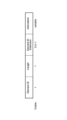
- FIG. 2 is a diagram showing an example of the format of Element.
- the information included in the Element is indicated by the Element ID.
- a set of multiple APs including a sharing AP and a shared AP is hereinafter referred to as an "AP set".
- AP set may be considered as a combination of sharing AP and shared AP, or may be considered as a set of APs that perform cooperative communication.
- control of the AP set includes the selection of APs included in the AP set, the method of transmitting and receiving information between the selected APs, and the like.
- Non-limiting embodiments of the present disclosure contribute to providing a method for selecting and controlling an appropriate AP set for cooperative communication.
- the wireless communication system may include, for example, AP 100 and STA 200.
- the AP 100 may have the functions of both a sharing AP and a shared AP, or it may have either one of the functions.
- FIG. 3A is a block diagram illustrating a partial configuration example of the AP 100 according to an embodiment of the present disclosure.
- FIG. 3B is a block diagram showing a partial configuration example of the STA 200.
- the AP 100 shown in FIG. 3A is an example of a communication device.
- the control unit 110 determines a communication partner device with which communication is possible (for example, another AP 100 that can communicate with the AP 100), and includes information indicating the communication partner device. Generate first cooperative control information.
- the wireless transmitting/receiving unit 101 (corresponding to an example of a transmitting circuit) transmits first cooperative control information to at least one communication partner device.
- the STA 200 shown in FIG. 3B is an example of a communication device.
- the wireless transmitter/receiver 201 receives the signal transmitted by the AP 100.
- Control unit 210 controls wireless communication with AP 100 based on control information included in the received signal.
- At least two APs are arranged and cooperative communication is controlled by sharing cooperative control information between the APs.
- the cooperative control information includes at least a cooperative possible AP list that is a list of cooperative APs.
- FIG. 4 is a block diagram showing a configuration example of STA 200 according to this embodiment.
- the STA 200 includes a wireless transmitting/receiving section 201, a transmitting packet generating section 202, a receiving packet decoding section 203, a receiving quality measuring section 204, and a control signal generating section 205.
- the transmission packet generation section 202, the reception packet decoding section 203, the reception quality measurement section 204, and the control signal generation section 205 may be included in the control section 210.
- the transmission packet generation section 202 generates a transmission packet from the transmission data and the control information output from the control signal generation section 205, and outputs it to the wireless transmission/reception section 201.
- the wireless transmission/reception unit 201 converts the transmission packet generated by the transmission packet generation unit 202 into a wireless signal, and transmits the converted wireless signal.
- Wireless transmitting/receiving section 201 receives a wireless signal and outputs the received wireless signal to received packet decoding section 203 and reception quality measuring section 204.
- the received packet decoding unit 203 decodes the wireless signal into packets and outputs received data from the decoded packets. Further, received packet decoding section 203 extracts control information from the decoded packet, and outputs the control information to control signal generation section 205 and reception quality measuring section 204.
- the reception quality measuring section 204 measures the reception quality based on the instruction of the control information included in the received packet and/or the internal state, and outputs the reception quality to the control signal generation section 205.
- the internal state may be, for example, the ability of the STA 200 (eg, Capability).
- the control signal generation section 205 generates control information from at least a portion of the transmission data, the control information output from the reception packet decoding section 203, the reception quality output from the reception quality measurement section 204, and the internal state. , outputs the generated control information to the transmission packet generation section 202.
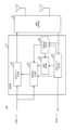
- FIG. 5 is a block diagram showing a configuration example of AP 100 according to this embodiment.
- AP 100 includes a wireless transmission/reception section 101, a transmission packet generation section 102, a reception packet decoding section 103, a reception quality measurement section 104, a control signal generation section 105, and a coordination control section 106.
- Transmission packet generation section 102 , reception packet decoding section 103 , reception quality measurement section 104 , control signal generation section 105 , and coordination control section 106 may be included in control section 110 .
- Transmission packet generation section 102 generates a transmission packet from at least a portion of the transmission data, the control information output from control signal generation section 105 , and the control information output from coordination control section 106 , and generates a transmission packet from wireless transmission/reception section 101 . Output to.
- the wireless transmission/reception unit 101 converts the transmission packet generated by the transmission packet generation unit 102 into a wireless signal, and transmits the converted wireless signal.
- Wireless transmitting/receiving section 101 receives a wireless signal and outputs the received wireless signal to received packet decoding section 103 and reception quality measuring section 104.
- the received packet decoding unit 103 decodes the wireless signal into packets, and outputs received data from the decoded packets. Further, received packet decoding section 103 extracts control information from the decoded packet, and outputs the control information to control signal generation section 105 , reception quality measurement section 104 , and coordination control section 106 .
- the reception quality measuring section 104 measures the reception quality based on the instruction of control information included in the packet and/or the internal state, and outputs the reception quality to the control signal generation section 105 and the cooperative control section 106.
- the internal state may be, for example, the ability of the AP 100 (eg, Capability).
- Control signal generation section 105 generates control information from at least a portion of the transmission data, the control information output from reception packet decoding section 103, the reception quality output from reception quality measurement section 104, and the internal state. , outputs the generated control information to the transmission packet generation section 102.
- the cooperative control unit 106 controls cooperative communication based on the control information output from the received packet decoding unit 103, the reception quality output from the reception quality measurement unit 104, and the internal state. Further, the cooperative control unit 106 generates control information related to control of cooperative communication, and outputs the control information to the transmission packet generating unit 102.
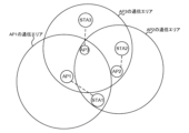
- FIG. 6 is a diagram showing an example of arrangement of communication devices in this embodiment.
- FIG. 6 shows the positional relationship between three APs (AP1, AP2, and AP3) and three STAs (STA1, STA2, and STA3). Further, FIG. 6 shows the communication areas of each of the three APs.
- FIG. 6 shows an example of the arrangement of three APs, the present disclosure is not limited thereto. There may be two APs, or four or more APs.
- an AP may be written as APn, APm, or APk in order to distinguish between N (N is an integer of 1 or more) different APs.
- n, m, and k may be identification information that identifies the AP.
- n is an integer greater than or equal to 1 and less than or equal to N.
- m is an integer different from n, and is an integer greater than or equal to 1 and less than or equal to N.
- k is an integer different from n and m, and is an integer greater than or equal to 1 and less than or equal to N.
- the present disclosure is not limited to the existence of three APs, APn, APm, and APk.
- the communication area of APn (in the example in Figure 6, n is one of 1, 2, or 3) may correspond to the range that the signals transmitted by APn reach, or the communication area with APn may correspond to the possible range.
- the communication area of APn may be defined based on the position of a communication device different from APn when APn can receive a signal transmitted by the communication device.
- the communication area of AP1 includes STA1 and AP3.
- the communication area of AP2 includes STA1, STA2, and AP3.
- the communication area of AP3 includes STA2, STA3, AP1, and AP2.
- STA1 is placed within the communication area of AP1 and AP2, and can receive signals transmitted from AP1 and AP2.
- STA2 is placed within the communication area of AP2 and AP3, and can receive signals transmitted from AP2 and AP3.
- STA3 is placed within the communication area of AP3 and can receive signals transmitted from AP3.
- the first communication device AP or STA
- can receive a signal transmitted from the second communication device an AP or STA different from the first communication device.
- the communication device may also be capable of receiving signals transmitted from the communication device.
- AP1 can receive a signal transmitted from AP3, and AP2 can receive a signal transmitted from AP3.
- AP1 and AP3 can perform cooperative control
- AP2 and AP3 can perform cooperative control.
- each AP performs cooperative control and transmits data to at least one of STA1, STA2, and STA3.
- FIG. 7 is a diagram showing a first example of the cooperative control procedure in this embodiment.
- the cooperative control procedure shown in FIG. 7 includes three steps: Multi-AP setup (step a), Multi-AP selection (step b), and Multi-AP transmission (step c).
- each AP performs Multi-AP setup and Multi-AP selection, and performs Multi-AP transmission based on cooperative control by sharing APs.
- Multi-AP setup step a
- Multi-AP selection step b
- Multi-AP transmission step c
- each AP performs Multi-AP setup and Multi-AP selection, and performs Multi-AP transmission based on cooperative control by sharing APs.
- Multi-AP setup is performed, for example, when APn is installed and when there is a change in APs existing around APn (hereinafter referred to as peripheral APs).
- peripheral APs APs existing around APn
- the case where the surrounding AP changes may correspond to the case where a new AP is added to the surrounding area and/or the case where the surrounding AP moves.
- APn may determine whether there is a change in the surrounding APs of APn based on whether there is a change in the reception quality of a signal (for example, a beacon) that APn receives from the surrounding APs.
- a signal for example, a beacon
- each AP detects a cooperative AP and registers or adds the detected cooperative AP to the cooperative AP list. For example, when APn receives a Beacon (also referred to as a beacon frame) of APm, which is another AP (hereinafter sometimes abbreviated as other AP), APn transmits the ID of APm that is the source of the Beacon to the cooperative AP. Add to list. Note that in this case, APm may be referred to as overlapping basic service set-AP (OBSS-AP).
- OBSS-AP overlapping basic service set-AP
- APn may add, for example, APk with which communication is possible via wired backhaul, in addition to APm, which is the source of the Beacon received by APn, to the APs that can cooperate with APn.
- ID of the AP registered in the cooperative AP list may be a BSS (basic service set) color, a MAC (Media Access Control) address, or a BSSID.
- whether or not registration is possible in the cooperation possible AP list may be determined based on other information (for example, cooperation permission information).
- the cooperation availability information may be included in at least one of Beacon, AP Capability, and BSS parameter.
- the cooperation availability information may be, for example, MAP (Multi-AP) rank information.
- an AP that has relatively low functionality and cannot cooperatively control other APs as a sharing AP may be defined as rank 0, and an AP that can operate as a sharing AP may be defined as rank 1.
- association or authentication may be performed between APs before and/or after registration in the cooperative AP list.
- the AP may set Candidate Set in the Multi-AP setup procedure.
- the Candidate Set may also be referred to as a multi-AP cooperation candidate set, an AP group, or the like.
- Candidate Set may be a group including multiple APs.
- APs that participate in a Candidate Set may be called controller APs, agent APs, coordinator APs, member APs, etc.
- sharing AP and shared AP may be determined within the Candidate Set.
- the AP may decide which APs to participate in the Candidate Set (APs included in the Candidate Set) from among the APs included in the cooperative AP list.
- the Candidate Set may include APs that are not included in the cooperative AP list.
- the AP may also determine that the cooperative AP list is a Candidate Set.
- the Candidate Set may be set by upper layer software of the AP (not shown in FIG. 5) and/or by the user. Then, configuration information regarding the settings of the Candidate Set (for example, an ID indicating the Candidate Set, a list of addresses of member APs) may be notified to the AP. For example, the configuration information may be notified to the cooperative control unit 106 of the AP 100.
- the upper layer software sets an ID value indicating Candidate Set in a MIB (Master Information Block) variable, and notifies the cooperative control unit 106 of the value.
- MIB Master Information Block
- upper layer software uses MLME SAP (MAC Layer Management Entity Service Access Point) primitives (interface information for controlling the MAC layer) when starting AP operation and/or when changing AP settings.
- MLME SAP MAC Layer Management Entity Service Access Point
- Candidate Set setting information may be included in the information and notified to the AP (for example, the cooperative control unit 106).
- An example of such a primitive is MLME-START.request (a primitive that requests the start of a BSS).
- primitives for configuring Multi-AP may be defined.
- the Candidate Set may be set by upper layer software and/or the user before the AP starts operating and/or independently of the AP operation.
- the Candidate Set may be set by communicating between APs. For example, when an APn receives a Beacon containing Capability information indicating that it supports the Multi-AP function from another APm, the APn exchanges Capability information with the other APm or the representative AP of the Candidate Set, and performs authentication procedures. You may decide whether to start or participate in a Candidate Set.
- APs After the Candidate Set is configured, communication between APs may become difficult. For example, after a Candidate Set has been configured (e.g., authentication between APs) via a wired connection and/or push button, temporary communication may become difficult. For example, in FIG. 6, when AP1, AP2, and AP3 are participating APs of the Candidate Set, it may be difficult for AP1 and AP2 to communicate directly.
- the AP that received the Beacon may be added to the list of APs that can cooperate. Further, it may be added to the cooperative AP list by referring to the delay requirements and the like for each Multi-AP cooperative communication method. For example, APs whose number of wireless backhaul connection stages is within a specified value may be added to the cooperative AP list. Note that the number of wireless backhaul connection stages may be the number obtained by adding 1 to the number of APs that relay the wireless backhaul connection. Note that the number of connection stages may be referred to as the number of hops.
- the setting and updating of the Candidate Set may be performed by upper layer software and/or the user.
- the setting and updating of the Candidate Set may be performed by upper layer software and/or instructions from the user, and the setting and updating of the cooperative AP list may be repeatedly performed by the AP.
- the AP may update the cooperative AP list every time it receives a Beacon.
- the AP may record the time of last communication with another AP, and exclude APs from the cooperative AP list for which a certain period of time has passed since the last communication time.
- the last communication time may correspond to, for example, the time closest to the current time among the times when communication was performed in the past than the current time.
- Multi-AP selection is performed to select a cooperative control method.
- each AP shares a cooperative AP list among neighboring APs, and selects a cooperative control method based on the cooperative AP list, for example.
- the nearby APs may be APs registered in the cooperative AP list or may be APs in the Candidate Set.
- a Beacon may be used to share the cooperative AP list, or individual communication between APs may be used. For example, association or individual communication after association may be used to share the cooperative AP list.
- selection of a sharing AP or adjustment of the probability of becoming a sharing AP may be performed, or specification of an operation in which a sharing AP requests control from an AP to be cooperatively controlled using, for example, a Trigger. You may do so.
- an AP that performs CSMA/CA operations may be selected from the cooperative AP list.
- an AP with the maximum number of cooperative APs in the cooperative AP list may perform a carrier sense operation in CSMA/CA.
- an AP that does not have the maximum number of cooperative APs in the cooperative AP list may not perform carrier sensing operation in CSMA/CA, or may stop carrier sensing operation.
- the AP with the maximum number of APs that can cooperate becomes the sharing AP, and the AP with the least number of APs that can cooperate (for example, an AP that has stopped carrier sense operation) becomes the shared AP.
- the time taken to obtain TXOP by CSMA/CA may be adjusted.
- the size of Backoff may be adjusted depending on the number of APs that can cooperate. For example, you can reduce the Backoff of the AP with the maximum number of APs that can cooperate in the list of APs that can cooperate, you can increase the Backoff of the AP with the minimum number of APs that can cooperate, or you can increase the Backoff of the AP with the minimum number of APs that can cooperate with each other. A fixed value depending on the number of APs may be added or subtracted. There is no particular limitation on the method of adjusting the size of Backoff.
- a fixed value when decreasing Backoff, a fixed value may be subtracted from the predefined Backoff, and when increasing Backoff, a fixed value may be added from the predefined Backoff.
- a fixed value corresponding to the number of APs capable of cooperation may be defined in a table format, and the fixed value defined according to the number of APs capable of cooperation may be added or subtracted.
- Multi-AP transmission In Multi-AP transmission, cooperative transmission is performed under the control of a sharing AP or an AP that performs cooperative control.
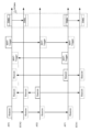
- FIG. 8 is a diagram illustrating a first example of operation of cooperative communication in this embodiment.
- FIG. 8 shows an operation example in which AP3 becomes a sharing AP due to Multi-AP selection and cooperative communication (for example, C-OFDMA) is executed by AP1, AP2, and AP3.
- FIG. 8 exemplifies signals transmitted and received between the communication devices shown in FIG. 6.
- AP1 detects the reception of the Beacon transmitted by AP3 by the wireless transmitter/receiver 101 and the received packet decoder 103, and the cooperative controller 106 allows AP3 to Register in the cooperative AP list.
- AP2 registers AP3 in its cooperative AP list.
- AP3 detects reception of the Beacon sent by AP1, registers AP1 in AP3's cooperative AP list, detects reception of the Beacon sent by AP2, and registers AP2 in AP3's cooperative AP list. do.
- each AP may limit the APs that are registered in the cooperation possible AP list by the cooperation control unit 106 to cases where the reception quality measured by the reception quality measurement unit 104 exceeds a threshold value. For example, APn registers APm in its cooperative AP list when the reception quality of the Beacon transmitted by APm exceeds the threshold, and registers APm in the list of APs that can cooperate with APn when the reception quality of the Beacon transmitted by APm does not exceed the threshold. There is no need to register it in APn's cooperative AP list.
- Multi-AP selection when each AP transmits the cooperative AP list to other APs, for example, the cooperative control unit 106 sends the cooperative AP list to the transmission packet generation unit 102. It may also be sent by including it in the Beacon generated.
- each AP receives a cooperative AP list from another AP, it extracts the cooperative AP list from the Beacon received by wireless transmitting/receiving section 101 and received packet decoding section 103, and stores it in cooperative control section 106. This allows the cooperative AP list to be shared between each AP.
- AP3 having the maximum number of APs registered in the cooperative AP list (number of cooperative APs) is selected as the sharing AP. In this case, AP1 and AP2 may stop carrier sensing operation.
- AP3 becomes a sharing AP, and AP3 transmits the MAP-Trigger generated by transmission packet generation section 102 using wireless transmission/reception section 101.
- AP1 and AP2 detect the MAP-Trigger of AP3 using wireless transmitting/receiving section 101 and received packet decoding section 103, respectively, and notify cooperative control section 106 of the detected MAP-Trigger.
- the cooperative control units 106 of AP1 and AP2 notify the transmission packet generation unit 102 that cooperative communication (for example, C-OFDMA) will be performed based on the MAP-Trigger and internal state notified from AP3.
- the wireless transmitting/receiving units 101 of AP1, AP2, and AP3 transmit the packets generated by the transmission packet generating unit 102, respectively, in the frequency band specified by the cooperative control unit 106 and the MAP-Trigger.
- each AP sends the cooperative AP list to other APs and shares the cooperative AP list of each AP with each other, thereby making it possible to perform appropriate cooperative communication in cooperative control using the cooperative AP list.
- a combination of APs can be realized. For example, in the example described above, cooperative operation by more APs is possible. Therefore, system throughput is improved. For example, in the example of FIG. 6, communication cannot be performed between AP1 and AP2, but by sharing the cooperative AP list, three APs including AP1 and AP2 can perform cooperative operations, and in cooperative communication Appropriate combinations of APs can be achieved, improving system throughput.
- APn may further transfer the cooperative AP list of another AP (for example, APm) to another AP (for example, APk) through inter-AP communication.
- AP3 transfers AP1's cooperative AP list to AP2, so that AP2 can obtain AP1's cooperative AP list.
- FIGS. 7 and 8 show an operation example in which Multi-AP selection is performed after Multi-AP setup
- Multi-AP selection or a part of processing of Multi-AP selection may be included in Multi-AP setup.
- a cooperative AP list may be shared between each AP, and a Candidate Set may be configured based on the cooperative AP list, or the cooperative AP list may be set as a Candidate Set.
- the cooperative control method may be determined in Multi-AP setup or Multi-AP selection, or may be limited to any cooperative control method in advance.
- the cooperative control method targeted here may be, for example, at least one of sharing AP selection, probability adjustment to become a sharing AP, and control using a trigger.
- the cooperative control method may be determined, for example, through negotiation at the time of AP association or authentication, or may be notified at the time of Multi-AP selection.
- FIG. 9 is a diagram showing a first example of the format of Element in this embodiment.
- FIG. 9 shows a format in which a cooperative AP list is added to the Element format shown in FIG. 2.
- an element having a format in which a cooperative AP list is added is referred to as a Multi-AP element, for example.
- the BSS color of other APs that can be cooperatively controlled by each AP is Included.
- the BSS colors of n APs that can be cooperatively controlled are included as an example.
- the Multi-AP element generated by AP1 includes the BSS color of AP3
- the Multi-AP element generated by AP2 includes the BSS color of AP3
- the Multi-AP element generated by AP3 includes the BSS colors of AP1 and AP2.
- the cooperative AP list may include MAP rank information. This can prevent a request for cooperative control from being made to an AP that cannot cooperatively control other APs as a sharing AP.
- the path loss between APs or the received power value of other APs may be added to the cooperative AP list. This makes it possible to control the transmission power of other APs in cooperative control.
- Example 2 In the second embodiment, an example will be described in which the configuration is the same as that of the first embodiment described above, but cooperation candidate information is added as information shared between APs.
- Multi-AP setup and Multi-AP transmission may be the same operations as in the first embodiment described above.
- cooperation candidate information is shared with neighboring APs.
- each AP shares cooperation candidate information and cooperation control information with neighboring APs.
- the cooperation candidate information may be included in the cooperative control information or may be handled separately from the cooperative control information.
- the cooperation candidate information may be information indicating the presence or absence of effective cooperative control, or may be information regarding the STA that is the target of cooperative communication.
- the cooperation candidate information may include information on STAs that are affected by interference from other APs.
- the cooperation candidate information generated by APn may include information about an STA that connects to APn and is affected by interference from APm.
- each AP may refer to the list of APs capable of cooperation in order to create cooperation candidate information.
- FIG. 10 is a diagram illustrating a second example of the cooperative communication operation according to the present embodiment.
- FIG. 10 shows an operation example in which AP3 becomes a sharing AP and cooperative communication (for example, C-OFDMA) is executed between AP1 and AP3.
- FIG. 10 exemplifies signals transmitted and received between the communication devices shown in FIG. 6.
- APn uses information about APm, which is another AP whose subordinate STAs (also referred to as associated STAs or BSS-STAs) are affected by interference, and information about APm, which is another AP whose subordinate STAs (also called associated STAs or BSS-STAs) are affected by interference. Collect information on STAs associated with APm that are receiving STAs (also called OBSS-STAs).
- the STA1 uses the wireless transmitting/receiving section 201 and the receiving packet decoding section 203 to detect reception of a Beacon transmitted by the AP2, and transmits the detection result to the transmitting packet generating section 202 and the wireless transmitting/receiving section 201. Send to. By transmitting this detection result, AP1 is notified that STA1 is affected by interference from AP2.
- FIG. 10 does not illustrate a procedure in which STA1 notifies AP1 of the interference effect, it can be performed as follows, for example.
- STA1 When STA1 receives a signal from an AP other than AP1 and/or a STA associated with an AP other than AP1 (for example, a signal such as a Beacon transmitted from AP2), STA1 interferes with the influence of the received signal. It is recorded as influence information, and all recorded interference influence information is notified to AP1.
- the procedure for notifying the interference impact information from STA1 to AP1 may be performed by STA1 voluntarily or based on a report request from AP1 after STA1 associates with AP1.
- AP1 sends an Association Request frame containing information on interference effects. may be notified.
- the notification of interference influence may be limited to a case where the reception quality measured by the reception quality measurement unit 204 exceeds a predetermined threshold. For example, if the reception quality of the Beacon sent by AP2 exceeds the threshold, STA1 notifies AP1 that STA1 will be affected by interference from AP2, and the reception quality of the Beacon sent by AP2 will not exceed the threshold. In this case, it is determined that STA1 is not affected by interference from AP2, and there is no need to notify AP1 of the interference effect.
- AP1 uses wireless transmitting/receiving section 101 and received packet decoding section 103 to obtain a notification that STA1 is affected by interference from AP2, and stores information indicated by the obtained notification in cooperative control section 106.
- AP1 can determine that AP3 can cooperatively control AP2, which AP1 cannot cooperatively control, from the cooperative possible AP list. Then, AP1 creates information indicating that STA1 is affected by interference from AP2 as cooperation candidate information to be transmitted to AP3, and transmits it to AP3 using transmission packet generation section 102 and wireless transmission/reception section 101.
- STA2 Similar to STA1, STA2 notifies AP2 that STA2 is affected by interference from AP3. AP2, which has received the notification, transmits information indicating that STA2 is affected by interference from AP3 to AP3 as cooperation candidate information, similarly to AP1 described above.
- STA3 is not affected by interference from other APs (AP1 and AP2), AP3 does not need to notify cooperation candidate information, and STA3 does not need to notify other APs (AP1 and AP2) that there is no interference. Or AP2) may be notified.
- cooperation candidate information may be limited.
- each AP may refer to the cooperative AP list and notify information regarding interference from APs that cannot perform direct cooperative control, but may not notify information regarding interference from APs that can perform direct cooperative control.
- the cooperative candidate information to be notified is the information that AP1 notifies AP3 (for example, information indicating that STA1 associated with AP1 is affected by interference from AP2). information).
- the cooperative candidate information to be notified is the information that AP1 notifies AP3 (for example, information indicating that STA1 associated with AP1 is affected by interference from AP2). information).
- AP2 and AP3 can perform direct cooperative control, information indicating that STA2 associated with AP2 is affected by interference from AP3 does not need to be notified from AP2 to AP3.
- Notification referring to the cooperative AP list can be performed, for example, as follows.
- STA1 receives the Beacon of AP1 and obtains a cooperative AP list included in the received Beacon. Since AP1 is located outside the signal reach area from AP2, AP2 is not included in the cooperative AP list of AP1. When STA1 receives a signal such as a beacon from AP2 that is not included in the cooperative AP list from AP1, STA1 notifies AP1 of information on interference from AP2. On the other hand, since AP3 is included in the cooperative AP list, STA1 recognizes that even if it receives a signal such as a beacon from AP3, it does not affect interference and does not notify AP1.
- Beacon may be used to notify the cooperation candidate information, or individual communication between APs may be used.
- AP1 may transmit a cooperative control request including cooperation candidate information to AP3, or AP3, which has received the cooperative control request, may transmit a cooperative control response to AP1.
- cooperation candidate state information information reflecting the cooperation candidate information
- cooperation candidate state information information reflecting the cooperation candidate information
- the ID of the interference source AP and/or interference source STA to be included in the cooperation candidate information may be the BSS color included in the packet received as interference.
- the information included in the cooperation candidate information that AP1 notifies AP3, which indicates that STA1 is affected by interference from AP2, is also included in the BSS color included in the packet that STA1 receives from AP2. good.
- Each AP stores cooperation candidate information decoded by the wireless transmission/reception unit 101 and received packet decoding unit 103 in the cooperation control unit 106.
- the coordination control unit 106 may perform coordination control with reference to coordination candidate information.
- cooperative communication with AP1 for example, C-OFDMA between AP1 and AP3 that has been notified of cooperation candidate information by MAP-Trigger may be specified.
- the amount of data and/or the transmission time desired to be transmitted in cooperative communication may be added to the cooperation candidate information.
- the amount of communication data and/or the transmission time between AP1 and STA1 may be added.
- cooperative control may be performed with reference to the amount of data included in the cooperation candidate information.
- C-OFDMA using AP1, AP2, and AP3 may be specified.
- AP1 when AP1 becomes a sharing AP, as shown in Figure 10, AP1 requests cooperative control to AP3 using MAP-Trigger, and AP3 uses MAP-Trigger to perform cooperative communication with AP1 (for example, AP1, AP3 C-OFDMA) may be specified.
- AP3 specifies C-OFDMA using AP1 and AP3, so that AP2, which has received AP3's MAP-Trigger, does not transmit. By not transmitting data from AP2, interference by AP2 can be suppressed (or eliminated) in communication between AP1 and STA1.
- AP1 sends the amount of data or transmission time that it wants to transmit cooperatively (in the example of FIG. 10, the amount of data and/or transmission time that it wants to transmit to STA1) in the MAP-Trigger that notifies AP3. May be included.
- AP1 and AP3 each have a trigger type (for example, "cooperative execution” or "cooperative execution") to distinguish between the MAP-Trigger transmitted by AP1 and the MAP-Trigger transmitted by AP3. "Request”) may be included in the MAP-Trigger.
- AP1 may autonomously refer to the cooperative AP list and request cooperative control from AP3 using MAP-Trigger.
- cooperation candidate information may not be used.
- each AP transmits the cooperation possible AP list (for example, cooperation control information) and cooperation candidate information to other APs, and by mutually sharing the cooperation possible AP list and cooperation candidate information of each AP.
- cooperation possible AP list for example, cooperation control information
- cooperation candidate information for example, cooperation control information
- an appropriate combination of APs can be realized in cooperative communication.
- cooperative operations can be performed that take into account the influence of interference, so system throughput can be improved.
- FIG. 11 is a diagram showing a second example of the format of Element in this embodiment.
- FIG. 11 shows an example in which the Multi-AP element shown in FIG. 9 includes information on STAs affected by interference as cooperation candidate information.
- the BSS color (“InterferenceBSScolor” in FIG. 11) and the amount of transmitted and received data (“Data Length” in FIG. 11) of other APs that cause interference are notified.
- the amount of transmitted data may be a value that integrates uplink and downlink data amounts and data amounts of multiple STAs.
- FIG. 11 shows an example in which the BSS color of other APs that cause interference is one, the format may also be such that the BSS colors of multiple other APs and/or multiple amounts of transmitted/received data can be specified. .
- the Multi-AP element of AP1 is information including the BSS color of AP2 and the data amount of STA1.
- AP3 can schedule the amount of data to be allocated to AP1, for example, in C-OFDMA.
- the Multi-AP element of AP1 is the sum of the data amount of STA1 and STA4.
- the information may include. This makes it possible to reduce the amount of data required for STA data amount notification. Further, the amount of STA data to be notified may be replaced by, for example, the packet transmission time when transmitted in a 20 MHz band. This eliminates the need for additional information (eg, MCS information, etc.) to determine the packet transmission time.
- Embodiment 3 shows an example in which some STAs have different requirements from other STAs.
- STA2 shown in FIG. 6 is a terminal that requires low latency (also referred to as low latency) will be described below.
- Multi-AP setup and Multi-AP transmission may be performed in the same manner as in the first and second embodiments.
- cooperation candidate information is shared with neighboring APs.
- the coordination candidate information in the coordination control unit 106 may include information on STAs that require low delay, or may include a value (for example, transmission time) that integrates information regarding multiple STAs.
- FIG. 12 is a diagram illustrating a third example of the cooperative communication operation according to the present embodiment.
- FIG. 12 shows an example of an operation in which AP3 becomes a sharing AP and cooperative communication (for example, C-OFDMA) is executed by AP1, AP2, and AP3.
- FIG. 12 exemplifies signals transmitted and received between the communication devices shown in FIG. 6.
- information about STA2, which requires low delay may be added to the cooperation candidate information.
- information about STA2 that requires low delay may be included in cooperation candidate information that limits the information to be transmitted.
- Multi-AP transmission when AP3 becomes a sharing AP, it is possible to specify cooperative communication with AP1 and AP2 (for example, C-OFDMA by AP1, AP2, and AP3) that have been notified of cooperation candidate information by MAP-Trigger. Cooperative communication may also be performed.
- AP1 and AP2 become sharing APs, similar to the second embodiment, cooperative control may be requested to AP3 using MAP-Trigger.
- communication between AP2 and STA2 is improved by adding the transmission of AP2 (that is, by performing C-OFDMA by AP1, AP2, and AP3). Delay can be reduced.
- STAs that require low latency may include NSEP (National Security and Emergency Preparedness) terminals.
- NSEP National Security and Emergency Preparedness
- FIG. 13 is a diagram showing a third example of the format of Element in this embodiment.
- FIG. 13 shows an example in which the Multi-AP element shown in FIG. 9 includes information on STA requiring low delay as cooperation candidate information.
- the amount of data transmitted and received by the STA for which low delay is required (“Data Length" in FIG. 13) is notified.
- the amount of data to be notified may be the amount of data that integrates the amount of data of multiple STAs, as in the second embodiment, or the amount of data may be replaced with the packet transmission time when transmitting in the 20MHz band, for example. It's okay.
- STA2 is an STA that requires low delay, so the Multi-AP element of AP2 is information that includes the data amount of STA2.
- FIG. 11 may be used instead of the format shown in FIG. 13.
- an identifier for identifying the STA for which low delay is required may be added to the InterferenceBSS color field shown in FIG. 11.
- the specific value of InterferenceBSS color may be replaced with a value indicating an STA for which low latency is required.
- the cooperation candidate information includes information on an STA that requires low delay. May be included.
- the cooperation candidate information may include information indicating that the STA requests to prevent interference from other APs.
- Example 4 In the fourth embodiment, an example will be described in which Multi-AP measurement is performed in the arrangement example shown in FIG. 6.
- FIG. 14 is a diagram showing a second example of the cooperative control procedure in this embodiment. As shown in FIG. 14, each AP performs Multi-AP setup (step d) and Multi-AP measurement (step e), and performs Multi-AP transmission (step f) based on cooperative control by the sharing AP.
- each AP shares the cooperative AP list shown in the Multi-AP setup and Multi-AP selection shown in Example 1 with neighboring APs.
- each AP performs measurement with reference to the cooperative AP list and reports the measurement results.
- Multi-AP transmission cooperative communication similar to the first, second, and third embodiments is performed with reference to the Multi-AP measurement notification results.
- FIG. 15 is a diagram illustrating a fourth example of the cooperative communication operation according to the present embodiment.
- FIG. 15 shows an operation example in which AP3 becomes a sharing AP and AP1 and AP3 perform cooperative communication (for example, C-OFDMA).
- FIG. 15 exemplifies signals transmitted and received between the communication devices shown in FIG. 6.
- each AP In the Multi-AP setup, each AP generates a cooperative AP list, similar to the Multi-AP setup in Example 1, and includes the cooperative AP list in the Beacon, similar to Multi-AP selection in Example 1. This notifies neighboring APs of the cooperative AP list.
- the cooperative control unit 106 of AP1 determines that AP3 is capable of cooperative control with AP2 from the cooperative possible AP list. Furthermore, the wireless transmitting/receiving section 101 and the received packet decoding section 103 of AP1 receive information on the received power or path loss between STA1 and AP2 from STA1 in advance. The received information on the received power or path loss between STA1 and AP2 is output to the transmission packet generation section 102. The transmission packet generation unit 102 of AP1 outputs a packet (for example, a report packet) including the received power or path loss between STA1 and AP2 to the wireless transmission/reception unit 101. The report packet is transmitted toward AP3 by the wireless transmitter/receiver 101.
- a packet for example, a report packet
- STA1 receives the Beacon of AP1 and obtains a list of APs that can cooperate included in the received Beacon. Since AP1 is located outside the signal reach area from AP2, AP2 is not included in the cooperative AP list of AP1.
- STA1 receives a signal such as a beacon from AP2 that is not included in the cooperative AP list from AP1, STA1 receives information on the received power or path loss between STA1 and AP2 based on the measurement results of the received signal. , and notify AP1 as a measurement report.
- AP2 and AP3 do not need to transmit report packets because there are no other APs that are affected by interference and that cannot be cooperatively controlled.
- the other AP affected by interference corresponds to, for example, APm whose STA associated with APn is affected by interference.
- the other APs that cannot be controlled cooperatively with APn correspond to APm that cannot communicate with APn.
- STA2 that associates with AP2 is located outside the signal reach area from AP1, so there is no interference from AP1 and it is affected by interference from AP3, but AP3 has no cooperative control with AP2. It is a possible AP.
- STA3 associated with AP3 is not affected by interference from AP1 and AP2. Therefore, AP2 and AP3 have no other APs that are affected by interference and that cannot be controlled cooperatively.
- Multi-AP transmission when AP3 becomes a sharing AP, cooperative communication can be performed by specifying cooperative communication with AP1, which is the source of the Report packet (for example, C-OFDMA between AP1 and AP3). good.
- each AP may update the cooperative AP list based on the measurement results, or may re-execute all or part of the setup procedure based on the updated cooperative AP list.
- APn may transmit measurement results between other APs and STAs (for example, STAs under APn) that it wants to perform cooperative control to other APs in a Report packet.
- the destination of the Report packet may be determined based on the cooperative AP list.
- AP1 may notify AP3 of the measurement results between STA1 and AP2.
- the amount of data transmitted and received by the STA may be added to the information transmitted in the Report packet.
- the measurement results may be aggregated in APs that are under cooperative control.
- the AP to be cooperatively controlled may be replaced with another name such as Master AP, Coordinator AP, multi-AP coordinator, Primary AP, central AP, and Controller AP.
- the AP that performs cooperative control may be described as Master AP.
- the Master AP may be selected based on the cooperative AP list.
- AP3 with the largest number of APs that can cooperate may be the Master AP. This allows AP3 to directly receive Report packets from AP1 and AP2, eliminating the need to transfer Report packets and preventing an increase in the amount of backhaul data.
- the presence or absence of a Master AP and the ID of the Master AP may be added to the cooperative AP list.
- the AP to be cooperatively controlled may be replaced with another name such as Slave AP, Coordinated AP, Secondary AP, associated AP, or Agent AP.
- an AP that is cooperatively controlled may be referred to as a slave AP. Note that authentication may be performed between the Master AP and the Slave AP when registering a Slave AP and/or when adding a Slave AP.
- the Slave AP may refer to the cooperative AP list to select the transfer route for the information to be notified to the Master AP.
- AP2 may refer to the cooperative AP list and send notification information to the Master AP to AP3 that can communicate with AP1.
- buffer status information, etc. may be included in the notification information to the Master AP.
- Example 1 Example 2, and Example 3 described above, examples of the cooperative AP list and cooperation candidate information in the Multi-AP element format were shown, but the present disclosure is not limited thereto.
- the Multi-AP element may have a format in which a cooperative AP list and cooperation candidate information are concatenated.
- the number of APs that can cooperate may be added to the format in order to clearly indicate the data length of the AP list that can cooperate.
- C-SR Coordinatd-Spatial Reuse
- C-BF Coordinatd Beamforming
- JT Joint Transmission
- at least one of the following is added to the cooperation candidate information shown in Embodiments 2 and 3: path loss information, received power, specified transmission power value of other APs (for example, attenuation from Beacon), channel information, etc. may be done.
- channel information etc. may be added to the measurement results shown in the fourth embodiment.
- Example 1 an example of setting a Candidate Set was shown, but even if the cooperative AP list is sent to the Master AP and the Master AP refers to the cooperative AP list and sets and updates the Candidate Set, good.
- a shared AP may send a trigger after a MAP-Trigger.
- the MAP-Trigger and the shared AP trigger may be set as the MU-RTS Trigger. This allows the neighboring APs and STAs to stop transmitting, reducing the effects of interference.
- a Multi-AP flag may be added to the Capability Information field to be notified using a Beacon, etc., and when there is information to be notified, the Multi-AP flag may be enabled, and notification may be made via a Beacon or individual communication.
- information such as MAP rank information may be information included in a format defined as a Multi-AP Capability element, for example.
- the information to be notified is not limited to the information shown in the above-described embodiment, and for example, other information may be added. Alternatively, at least part of the defined information may be deleted.
- frame, element, field, subfield, etc. are areas (ranges or configurations) included in a signal, and are examples of names for areas (ranges or configurations) in which information is set. . These terms may be read interchangeably.
- the AP that instructs cooperative communication and the AP that is instructed to perform cooperative communication are explained using the terms “Sharing AP” and “Shared AP,” respectively. Terms may be used.
- the explanation has been made based on the 11be format as a non-limiting example, but the format to which an embodiment of the present disclosure can be applied is not limited to the 11be format.
- An embodiment of the present disclosure may be applied, for example, to IEEE 802.11bd (NGV (Next Generation V2X)), which is the next generation standard of IEEE 802.11p, which is an in-vehicle standard.
- NVG Next Generation V2X
- Each functional block used in the description of the above embodiment is partially or entirely realized as an LSI that is an integrated circuit, and each process explained in the above embodiment is partially or entirely realized as an LSI, which is an integrated circuit. It may be controlled by one LSI or a combination of LSIs.
- the LSI may be composed of individual chips, or may be composed of a single chip that includes some or all of the functional blocks.
- the LSI may include data input and output.
- LSIs are sometimes called ICs, system LSIs, super LSIs, and ultra LSIs depending on the degree of integration.
- the method of circuit integration is not limited to LSI, and may be realized using a dedicated circuit, a general-purpose processor, or a dedicated processor. Furthermore, an FPGA (Field Programmable Gate Array) that can be programmed after the LSI is manufactured or a reconfigurable processor that can reconfigure the connections and settings of circuit cells inside the LSI may be used.
- FPGA Field Programmable Gate Array
- reconfigurable processor that can reconfigure the connections and settings of circuit cells inside the LSI may be used.
- the present disclosure may be implemented as digital or analog processing.
- the present disclosure can be implemented in all types of devices, devices, and systems (collectively referred to as communication devices) that have communication capabilities.
- the communication device may include a wireless transceiver and processing/control circuitry.
- the wireless transceiver may include a receiving section and a transmitting section, or both as functions.
- the wireless transceiver (transmitter, receiver) may include an RF (Radio Frequency) module and one or more antennas.
- RF modules may include amplifiers, RF modulators/demodulators, or the like.
- Non-limiting examples of communication devices include telephones (mobile phones, smart phones, etc.), tablets, personal computers (PCs) (laptops, desktops, notebooks, etc.), cameras (digital still/video cameras, etc.) ), digital players (e.g.
- digital audio/video players wearable devices (e.g. wearable cameras, smartwatches, tracking devices), game consoles, digital book readers, telehealth/telemedicine (e.g. devices (care/medicine prescriptions), vehicles or mobile vehicles with communication capabilities (cars, airplanes, ships, etc.), and combinations of the various devices described above.
- wearable devices e.g. wearable cameras, smartwatches, tracking devices
- game consoles digital book readers
- telehealth/telemedicine e.g. devices (care/medicine prescriptions), vehicles or mobile vehicles with communication capabilities (cars, airplanes, ships, etc.), and combinations of the various devices described above.
- Communication equipment is not limited to portable or movable, but also non-portable or fixed equipment, devices, systems, such as smart home devices (home appliances, lighting equipment, smart meters or It also includes measuring instruments, control panels, etc.), vending machines, and any other "things” that can exist on an Internet of Things (IoT) network.
- IoT Internet of Things
- Communication includes data communication using cellular systems, wireless LAN systems, communication satellite systems, etc., as well as data communication using a combination of these.
- Communication devices also include devices such as controllers and sensors that are connected or coupled to communication devices that perform the communication functions described in this disclosure. Examples include controllers and sensors that generate control and data signals used by communication devices to perform communication functions of a communication device.
- Communication equipment also includes infrastructure equipment, such as base stations, access points, and any other equipment, devices, or systems that communicate with or control the various equipment described above, without limitation. .
- a communication device includes a control circuit that determines a communication partner device with which communication is possible and generates first cooperative control information including information indicating the communication partner device; and a transmitting circuit for transmitting data to at least one communication partner device.
- a receiving circuit that receives, from at least one of the communication partner devices, second cooperative control information including information indicating a third communication device with which the at least one communication partner device can communicate. Equipped with
- the first cooperative control information includes information indicating the presence or absence of effective cooperative control.
- the first cooperative control information includes information that integrates information regarding a plurality of fourth communication devices associated with the communication device.
- the first cooperative control information includes information regarding a channel between the communication device and a fourth communication device that is associated with the communication device.
- the first cooperative control information may include an amount of data to be transmitted to a fourth communication device associated with the communication device and/or an amount of data received from the fourth communication device. Contains information indicating quantity.
- the first cooperative control information includes information regarding interference received by a fourth communication device associated with the communication device.
- the first cooperative control information includes information regarding the capability of a fourth communication device that associates with the communication device, or information regarding a request of the fourth communication device.
- the transmitting circuit transmits the first cooperative control information using a beacon.
- a communication device determines a communication partner device with which communication is possible, generates first cooperative control information including information indicating the communication partner device, and generates first cooperative control information including information indicating the communication partner device. The information is transmitted to at least one of the communication partner devices.
- An embodiment of the present disclosure is useful for wireless communication systems.
Abstract
L'invention concerne un dispositif de communication comprenant un circuit de commande pour déterminer un dispositif partenaire de communication avec lequel une communication est possible et générer des premières informations de commande coopérative comprenant des informations indiquant le dispositif partenaire de communication, et un circuit de transmission pour transmettre les informations de commande coopérative à au moins un dispositif partenaire de communication.
Applications Claiming Priority (2)
| Application Number | Priority Date | Filing Date | Title |
|---|---|---|---|
| JP2022-049958 | 2022-03-25 | ||
| JP2022049958 | 2022-03-25 |
Publications (1)
| Publication Number | Publication Date |
|---|---|
| WO2023181965A1 true WO2023181965A1 (fr) | 2023-09-28 |
Family
ID=88101281
Family Applications (1)
| Application Number | Title | Priority Date | Filing Date |
|---|---|---|---|
| PCT/JP2023/009046 WO2023181965A1 (fr) | 2022-03-25 | 2023-03-09 | Dispositif de communication et procédé de communication |
Country Status (1)
| Country | Link |
|---|---|
| WO (1) | WO2023181965A1 (fr) |
Citations (3)
| Publication number | Priority date | Publication date | Assignee | Title |
|---|---|---|---|---|
| WO2021010132A1 (fr) * | 2019-07-12 | 2021-01-21 | ソニー株式会社 | Dispositif et procédé de commande de communication, dispositif et procédé de communication sans fil et terminal de communication sans fil |
| JP2021513783A (ja) * | 2018-02-08 | 2021-05-27 | 華為技術有限公司Huawei Technologies Co.,Ltd. | 協調マルチアクセスポイントap伝送のための方法および関連装置 |
| WO2021239930A1 (fr) * | 2020-05-29 | 2021-12-02 | Canon Kabushiki Kaisha | Procédés et appareils de synchronisation dans une coordination multi-ap |
-
2023
- 2023-03-09 WO PCT/JP2023/009046 patent/WO2023181965A1/fr unknown
Patent Citations (3)
| Publication number | Priority date | Publication date | Assignee | Title |
|---|---|---|---|---|
| JP2021513783A (ja) * | 2018-02-08 | 2021-05-27 | 華為技術有限公司Huawei Technologies Co.,Ltd. | 協調マルチアクセスポイントap伝送のための方法および関連装置 |
| WO2021010132A1 (fr) * | 2019-07-12 | 2021-01-21 | ソニー株式会社 | Dispositif et procédé de commande de communication, dispositif et procédé de communication sans fil et terminal de communication sans fil |
| WO2021239930A1 (fr) * | 2020-05-29 | 2021-12-02 | Canon Kabushiki Kaisha | Procédés et appareils de synchronisation dans une coordination multi-ap |
Non-Patent Citations (3)
| Title |
|---|
| JASON YUCHEN GUO (HUAWEI TECHNOLOGIES CO. LTD.): "coordinated spatial reuse operation", IEEE DRAFT; 11-20-0033-01-00BE-COORDINATED-SPATIAL-REUSE-OPERATION, IEEE-SA MENTOR, PISCATAWAY, NJ USA, vol. 802.11 EHT; 802.11be, no. 1, 6 February 2020 (2020-02-06), Piscataway, NJ USA , pages 1 - 14, XP068165614 * |
| JONGHUN HAN (SAMSUNG): "Shared TXOP Spatial Reuse Considerations", IEEE DRAFT; 11-20-0590-05-00BE-SHARED-TXOP-SPATIAL-REUSE-CONSIDERATIONS, IEEE-SA MENTOR, PISCATAWAY, NJ USA, vol. 802.11 EHT; 802.11be, no. 5, 30 September 2020 (2020-09-30), Piscataway, NJ USA , pages 1 - 24, XP068173658 * |
| SUNGJIN PARK (LG ELECTRONICS): "Setup for Multi-AP coordination", IEEE DRAFT; 11-19-1895-02-00BE-SETUP-FOR-MULTI-AP-COORDINATION, IEEE-SA MENTOR, PISCATAWAY, NJ USA, vol. 802.11 EHT; 802.11be, no. 2, 16 January 2020 (2020-01-16), Piscataway, NJ USA , pages 1 - 15, XP068165406 * |
Similar Documents
| Publication | Publication Date | Title |
|---|---|---|
| US20210212150A1 (en) | Method and apparatus for multi-link operations | |
| TWI729984B (zh) | 終端裝置及藉由屬於不同蜂巢式系統的終端裝置來控制裝置間通信的方法 | |
| EP3637918B1 (fr) | Appareil électronique, dispositif de communication sans fil et procédé de communication sans fil | |
| US10944449B2 (en) | Apparatus and method in wireless communication system, and computer readable storage medium | |
| US11387886B2 (en) | Electronic device, method for same and information processing device | |
| JP2008532424A (ja) | 802.11仕様の下で作動するセクター化無線通信ネットワーク | |
| AU2024201611A1 (en) | Communication method applied to multi-link device in wireless local area network, and device | |
| US10433323B2 (en) | Communication control station device, communication terminal device, and communication control method | |
| US11510049B2 (en) | Control device, method, and recording medium | |
| JP2004274765A (ja) | 無線lanシステムおよびその使用方法 | |
| WO2022190677A1 (fr) | Terminal, point d'accès, et procédé de communication | |
| CN116234061A (zh) | 探测mld的请求和响应方法及站点,接入点 | |
| WO2023181965A1 (fr) | Dispositif de communication et procédé de communication | |
| US20220418022A1 (en) | Operating Channel Validation | |
| WO2022253150A1 (fr) | Procédé et appareil de transmission de données | |
| WO2022030213A1 (fr) | Dispositif de communication sans fil et procédé de communication sans fil | |
| WO2024009838A1 (fr) | Dispositif de communication et procédé de communication | |
| WO2022079992A1 (fr) | Terminal, dispositif de communication et procédé de communication | |
| WO2013035968A1 (fr) | Unité d'émission/réception sans fil pour fournir des services ou activités dans un réseau local sans fil | |
| US20230319722A1 (en) | Multi-link single radio suspension and operating parameters | |
| KR20180005999A (ko) | 다중망 병합 전송을 위한 단말, 그리고 이의 동작 방법 | |
| KR20240036014A (ko) | 통신 장치 및 통신 방법 | |
| JP2019165481A (ja) | 装置及び方法 |
Legal Events
| Date | Code | Title | Description |
|---|---|---|---|
| 121 | Ep: the epo has been informed by wipo that ep was designated in this application |
Ref document number: 23774564 Country of ref document: EP Kind code of ref document: A1 |