WO2023181965A1 - Communication device and communication method - Google Patents
Communication device and communication method Download PDFInfo
- Publication number
- WO2023181965A1 WO2023181965A1 PCT/JP2023/009046 JP2023009046W WO2023181965A1 WO 2023181965 A1 WO2023181965 A1 WO 2023181965A1 JP 2023009046 W JP2023009046 W JP 2023009046W WO 2023181965 A1 WO2023181965 A1 WO 2023181965A1
- Authority
- WO
- WIPO (PCT)
- Prior art keywords
- cooperative
- communication
- information
- aps
- communication device
- Prior art date
Links
- 238000004891 communication Methods 0.000 title claims abstract description 196
- 238000000034 method Methods 0.000 title claims description 36
- 230000005540 biological transmission Effects 0.000 abstract description 66
- 101100161473 Arabidopsis thaliana ABCB25 gene Proteins 0.000 description 47
- 101100096893 Mus musculus Sult2a1 gene Proteins 0.000 description 47
- 101150081243 STA1 gene Proteins 0.000 description 47
- 238000010586 diagram Methods 0.000 description 32
- 238000005259 measurement Methods 0.000 description 26
- OVGWMUWIRHGGJP-WVDJAODQSA-N (z)-7-[(1s,3r,4r,5s)-3-[(e,3r)-3-hydroxyoct-1-enyl]-6-thiabicyclo[3.1.1]heptan-4-yl]hept-5-enoic acid Chemical compound OC(=O)CCC\C=C/C[C@@H]1[C@@H](/C=C/[C@H](O)CCCCC)C[C@@H]2S[C@H]1C2 OVGWMUWIRHGGJP-WVDJAODQSA-N 0.000 description 17
- 101000988961 Escherichia coli Heat-stable enterotoxin A2 Proteins 0.000 description 17
- 230000007274 generation of a signal involved in cell-cell signaling Effects 0.000 description 12
- 101000752249 Homo sapiens Rho guanine nucleotide exchange factor 3 Proteins 0.000 description 8
- 102100021689 Rho guanine nucleotide exchange factor 3 Human genes 0.000 description 8
- 230000000694 effects Effects 0.000 description 7
- 101100172132 Mus musculus Eif3a gene Proteins 0.000 description 5
- 238000005516 engineering process Methods 0.000 description 4
- 238000012546 transfer Methods 0.000 description 4
- 230000008859 change Effects 0.000 description 3
- 239000003086 colorant Substances 0.000 description 3
- 239000000284 extract Substances 0.000 description 3
- 238000012545 processing Methods 0.000 description 3
- 101100395869 Escherichia coli sta3 gene Proteins 0.000 description 2
- 239000003795 chemical substances by application Substances 0.000 description 2
- 238000001514 detection method Methods 0.000 description 2
- 230000010354 integration Effects 0.000 description 2
- 230000004044 response Effects 0.000 description 2
- 101000692648 Avena sativa Phytochrome A type 3 Proteins 0.000 description 1
- FGUUSXIOTUKUDN-IBGZPJMESA-N C1(=CC=CC=C1)N1C2=C(NC([C@H](C1)NC=1OC(=NN=1)C1=CC=CC=C1)=O)C=CC=C2 Chemical compound C1(=CC=CC=C1)N1C2=C(NC([C@H](C1)NC=1OC(=NN=1)C1=CC=CC=C1)=O)C=CC=C2 FGUUSXIOTUKUDN-IBGZPJMESA-N 0.000 description 1
- 235000008694 Humulus lupulus Nutrition 0.000 description 1
- 230000001413 cellular effect Effects 0.000 description 1
- 238000004590 computer program Methods 0.000 description 1
- 230000003247 decreasing effect Effects 0.000 description 1
- 239000003814 drug Substances 0.000 description 1
- 230000002093 peripheral effect Effects 0.000 description 1
- 230000008569 process Effects 0.000 description 1
- 239000004065 semiconductor Substances 0.000 description 1
Images


Classifications
-
- H—ELECTRICITY
- H04—ELECTRIC COMMUNICATION TECHNIQUE
- H04W—WIRELESS COMMUNICATION NETWORKS
- H04W28/00—Network traffic management; Network resource management
- H04W28/16—Central resource management; Negotiation of resources or communication parameters, e.g. negotiating bandwidth or QoS [Quality of Service]
-
- H—ELECTRICITY
- H04—ELECTRIC COMMUNICATION TECHNIQUE
- H04W—WIRELESS COMMUNICATION NETWORKS
- H04W92/00—Interfaces specially adapted for wireless communication networks
- H04W92/16—Interfaces between hierarchically similar devices
- H04W92/20—Interfaces between hierarchically similar devices between access points
Definitions
- the present disclosure relates to a communication device and a communication method.
- LAN next-generation wireless local area networks
- 11ax IEEE 802.11ax
- AP Access Points
- STA Session
- ⁇ cooperative communication'' Multi-AP coordination
- Non-limiting embodiments of the present disclosure contribute to providing a communication device and a communication method that can realize an appropriate combination of communication devices in cooperative communication.
- a communication device includes a control circuit that determines a communication partner device with which communication is possible and generates first cooperative control information including information indicating the communication partner device; and a transmitting circuit for transmitting data to at least one communication partner device.
- an appropriate combination of communication devices can be realized in cooperative communication.
- Diagram showing an example of cooperative communication configuration Diagram showing an example of Element format A block diagram showing a partial configuration example of an AP according to an embodiment of the present disclosure
- a block diagram showing a partial configuration example of an STA according to an embodiment of the present disclosure A block diagram showing an example of the configuration of STA according to an embodiment
- a block diagram showing an example of the configuration of an AP according to an embodiment A diagram showing an example of arrangement of communication devices in an embodiment
- a diagram showing a first example of a cooperative control procedure in an embodiment A diagram showing a first example of an operation example of cooperative communication in an embodiment
- a diagram showing a first example of the format of Element in one embodiment A diagram illustrating a second example of cooperative communication operation in an embodiment.
- a diagram showing a second example of the format of Element in one embodiment A diagram illustrating a third example of cooperative communication operation in an embodiment.
- a diagram showing a third example of the format of Element in one embodiment A diagram showing a second example of a cooperative control procedure in an embodiment
- Non-Patent Document 1 In cooperative communication, methods of using wireless backhaul and methods of using wired backhaul are being considered as methods of transferring information between multiple APs (for example, Non-Patent Document 1).
- FIG. 1 is a diagram illustrating a configuration example of cooperative communication.
- Cooperative communication is performed, for example, by an AP called a sharing AP and an AP called a shared AP.
- an AP that has acquired a channel usage period (Transmission Opportunity (TXOP)) through CSMA/CA (Carrier Sense Multiple Access/Collision Avoidance) is called a sharing AP.
- TXOP Transmission Opportunity
- CA Carrier Sense Multiple Access/Collision Avoidance
- a shared AP an AP that is cooperatively controlled by a sharing AP.
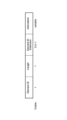
- FIG. 2 is a diagram showing an example of the format of Element.
- the information included in the Element is indicated by the Element ID.
- a set of multiple APs including a sharing AP and a shared AP is hereinafter referred to as an "AP set".
- AP set may be considered as a combination of sharing AP and shared AP, or may be considered as a set of APs that perform cooperative communication.
- control of the AP set includes the selection of APs included in the AP set, the method of transmitting and receiving information between the selected APs, and the like.
- Non-limiting embodiments of the present disclosure contribute to providing a method for selecting and controlling an appropriate AP set for cooperative communication.
- the wireless communication system may include, for example, AP 100 and STA 200.
- the AP 100 may have the functions of both a sharing AP and a shared AP, or it may have either one of the functions.
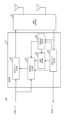
- FIG. 3A is a block diagram illustrating a partial configuration example of the AP 100 according to an embodiment of the present disclosure.
- FIG. 3B is a block diagram showing a partial configuration example of the STA 200.
- the AP 100 shown in FIG. 3A is an example of a communication device.
- the control unit 110 determines a communication partner device with which communication is possible (for example, another AP 100 that can communicate with the AP 100), and includes information indicating the communication partner device. Generate first cooperative control information.
- the wireless transmitting/receiving unit 101 (corresponding to an example of a transmitting circuit) transmits first cooperative control information to at least one communication partner device.
- the STA 200 shown in FIG. 3B is an example of a communication device.
- the wireless transmitter/receiver 201 receives the signal transmitted by the AP 100.
- Control unit 210 controls wireless communication with AP 100 based on control information included in the received signal.
- At least two APs are arranged and cooperative communication is controlled by sharing cooperative control information between the APs.
- the cooperative control information includes at least a cooperative possible AP list that is a list of cooperative APs.
- FIG. 4 is a block diagram showing a configuration example of STA 200 according to this embodiment.
- the STA 200 includes a wireless transmitting/receiving section 201, a transmitting packet generating section 202, a receiving packet decoding section 203, a receiving quality measuring section 204, and a control signal generating section 205.
- the transmission packet generation section 202, the reception packet decoding section 203, the reception quality measurement section 204, and the control signal generation section 205 may be included in the control section 210.
- the transmission packet generation section 202 generates a transmission packet from the transmission data and the control information output from the control signal generation section 205, and outputs it to the wireless transmission/reception section 201.
- the wireless transmission/reception unit 201 converts the transmission packet generated by the transmission packet generation unit 202 into a wireless signal, and transmits the converted wireless signal.
- Wireless transmitting/receiving section 201 receives a wireless signal and outputs the received wireless signal to received packet decoding section 203 and reception quality measuring section 204.
- the received packet decoding unit 203 decodes the wireless signal into packets and outputs received data from the decoded packets. Further, received packet decoding section 203 extracts control information from the decoded packet, and outputs the control information to control signal generation section 205 and reception quality measuring section 204.
- the reception quality measuring section 204 measures the reception quality based on the instruction of the control information included in the received packet and/or the internal state, and outputs the reception quality to the control signal generation section 205.
- the internal state may be, for example, the ability of the STA 200 (eg, Capability).
- the control signal generation section 205 generates control information from at least a portion of the transmission data, the control information output from the reception packet decoding section 203, the reception quality output from the reception quality measurement section 204, and the internal state. , outputs the generated control information to the transmission packet generation section 202.
- FIG. 5 is a block diagram showing a configuration example of AP 100 according to this embodiment.
- AP 100 includes a wireless transmission/reception section 101, a transmission packet generation section 102, a reception packet decoding section 103, a reception quality measurement section 104, a control signal generation section 105, and a coordination control section 106.
- Transmission packet generation section 102 , reception packet decoding section 103 , reception quality measurement section 104 , control signal generation section 105 , and coordination control section 106 may be included in control section 110 .
- Transmission packet generation section 102 generates a transmission packet from at least a portion of the transmission data, the control information output from control signal generation section 105 , and the control information output from coordination control section 106 , and generates a transmission packet from wireless transmission/reception section 101 . Output to.
- the wireless transmission/reception unit 101 converts the transmission packet generated by the transmission packet generation unit 102 into a wireless signal, and transmits the converted wireless signal.
- Wireless transmitting/receiving section 101 receives a wireless signal and outputs the received wireless signal to received packet decoding section 103 and reception quality measuring section 104.
- the received packet decoding unit 103 decodes the wireless signal into packets, and outputs received data from the decoded packets. Further, received packet decoding section 103 extracts control information from the decoded packet, and outputs the control information to control signal generation section 105 , reception quality measurement section 104 , and coordination control section 106 .
- the reception quality measuring section 104 measures the reception quality based on the instruction of control information included in the packet and/or the internal state, and outputs the reception quality to the control signal generation section 105 and the cooperative control section 106.
- the internal state may be, for example, the ability of the AP 100 (eg, Capability).
- Control signal generation section 105 generates control information from at least a portion of the transmission data, the control information output from reception packet decoding section 103, the reception quality output from reception quality measurement section 104, and the internal state. , outputs the generated control information to the transmission packet generation section 102.
- the cooperative control unit 106 controls cooperative communication based on the control information output from the received packet decoding unit 103, the reception quality output from the reception quality measurement unit 104, and the internal state. Further, the cooperative control unit 106 generates control information related to control of cooperative communication, and outputs the control information to the transmission packet generating unit 102.
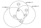
- FIG. 6 is a diagram showing an example of arrangement of communication devices in this embodiment.
- FIG. 6 shows the positional relationship between three APs (AP1, AP2, and AP3) and three STAs (STA1, STA2, and STA3). Further, FIG. 6 shows the communication areas of each of the three APs.
- FIG. 6 shows an example of the arrangement of three APs, the present disclosure is not limited thereto. There may be two APs, or four or more APs.
- an AP may be written as APn, APm, or APk in order to distinguish between N (N is an integer of 1 or more) different APs.
- n, m, and k may be identification information that identifies the AP.
- n is an integer greater than or equal to 1 and less than or equal to N.
- m is an integer different from n, and is an integer greater than or equal to 1 and less than or equal to N.
- k is an integer different from n and m, and is an integer greater than or equal to 1 and less than or equal to N.
- the present disclosure is not limited to the existence of three APs, APn, APm, and APk.
- the communication area of APn (in the example in Figure 6, n is one of 1, 2, or 3) may correspond to the range that the signals transmitted by APn reach, or the communication area with APn may correspond to the possible range.
- the communication area of APn may be defined based on the position of a communication device different from APn when APn can receive a signal transmitted by the communication device.
- the communication area of AP1 includes STA1 and AP3.
- the communication area of AP2 includes STA1, STA2, and AP3.
- the communication area of AP3 includes STA2, STA3, AP1, and AP2.
- STA1 is placed within the communication area of AP1 and AP2, and can receive signals transmitted from AP1 and AP2.
- STA2 is placed within the communication area of AP2 and AP3, and can receive signals transmitted from AP2 and AP3.
- STA3 is placed within the communication area of AP3 and can receive signals transmitted from AP3.
- the first communication device AP or STA
- can receive a signal transmitted from the second communication device an AP or STA different from the first communication device.
- the communication device may also be capable of receiving signals transmitted from the communication device.
- AP1 can receive a signal transmitted from AP3, and AP2 can receive a signal transmitted from AP3.
- AP1 and AP3 can perform cooperative control
- AP2 and AP3 can perform cooperative control.
- each AP performs cooperative control and transmits data to at least one of STA1, STA2, and STA3.
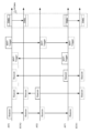
- FIG. 7 is a diagram showing a first example of the cooperative control procedure in this embodiment.
- the cooperative control procedure shown in FIG. 7 includes three steps: Multi-AP setup (step a), Multi-AP selection (step b), and Multi-AP transmission (step c).
- each AP performs Multi-AP setup and Multi-AP selection, and performs Multi-AP transmission based on cooperative control by sharing APs.
- Multi-AP setup step a
- Multi-AP selection step b
- Multi-AP transmission step c
- each AP performs Multi-AP setup and Multi-AP selection, and performs Multi-AP transmission based on cooperative control by sharing APs.
- Multi-AP setup is performed, for example, when APn is installed and when there is a change in APs existing around APn (hereinafter referred to as peripheral APs).
- peripheral APs APs existing around APn
- the case where the surrounding AP changes may correspond to the case where a new AP is added to the surrounding area and/or the case where the surrounding AP moves.
- APn may determine whether there is a change in the surrounding APs of APn based on whether there is a change in the reception quality of a signal (for example, a beacon) that APn receives from the surrounding APs.
- a signal for example, a beacon
- each AP detects a cooperative AP and registers or adds the detected cooperative AP to the cooperative AP list. For example, when APn receives a Beacon (also referred to as a beacon frame) of APm, which is another AP (hereinafter sometimes abbreviated as other AP), APn transmits the ID of APm that is the source of the Beacon to the cooperative AP. Add to list. Note that in this case, APm may be referred to as overlapping basic service set-AP (OBSS-AP).
- OBSS-AP overlapping basic service set-AP
- APn may add, for example, APk with which communication is possible via wired backhaul, in addition to APm, which is the source of the Beacon received by APn, to the APs that can cooperate with APn.
- ID of the AP registered in the cooperative AP list may be a BSS (basic service set) color, a MAC (Media Access Control) address, or a BSSID.
- whether or not registration is possible in the cooperation possible AP list may be determined based on other information (for example, cooperation permission information).
- the cooperation availability information may be included in at least one of Beacon, AP Capability, and BSS parameter.
- the cooperation availability information may be, for example, MAP (Multi-AP) rank information.
- an AP that has relatively low functionality and cannot cooperatively control other APs as a sharing AP may be defined as rank 0, and an AP that can operate as a sharing AP may be defined as rank 1.
- association or authentication may be performed between APs before and/or after registration in the cooperative AP list.
- the AP may set Candidate Set in the Multi-AP setup procedure.
- the Candidate Set may also be referred to as a multi-AP cooperation candidate set, an AP group, or the like.
- Candidate Set may be a group including multiple APs.
- APs that participate in a Candidate Set may be called controller APs, agent APs, coordinator APs, member APs, etc.
- sharing AP and shared AP may be determined within the Candidate Set.
- the AP may decide which APs to participate in the Candidate Set (APs included in the Candidate Set) from among the APs included in the cooperative AP list.
- the Candidate Set may include APs that are not included in the cooperative AP list.
- the AP may also determine that the cooperative AP list is a Candidate Set.
- the Candidate Set may be set by upper layer software of the AP (not shown in FIG. 5) and/or by the user. Then, configuration information regarding the settings of the Candidate Set (for example, an ID indicating the Candidate Set, a list of addresses of member APs) may be notified to the AP. For example, the configuration information may be notified to the cooperative control unit 106 of the AP 100.
- the upper layer software sets an ID value indicating Candidate Set in a MIB (Master Information Block) variable, and notifies the cooperative control unit 106 of the value.
- MIB Master Information Block
- upper layer software uses MLME SAP (MAC Layer Management Entity Service Access Point) primitives (interface information for controlling the MAC layer) when starting AP operation and/or when changing AP settings.
- MLME SAP MAC Layer Management Entity Service Access Point
- Candidate Set setting information may be included in the information and notified to the AP (for example, the cooperative control unit 106).
- An example of such a primitive is MLME-START.request (a primitive that requests the start of a BSS).
- primitives for configuring Multi-AP may be defined.
- the Candidate Set may be set by upper layer software and/or the user before the AP starts operating and/or independently of the AP operation.
- the Candidate Set may be set by communicating between APs. For example, when an APn receives a Beacon containing Capability information indicating that it supports the Multi-AP function from another APm, the APn exchanges Capability information with the other APm or the representative AP of the Candidate Set, and performs authentication procedures. You may decide whether to start or participate in a Candidate Set.
- APs After the Candidate Set is configured, communication between APs may become difficult. For example, after a Candidate Set has been configured (e.g., authentication between APs) via a wired connection and/or push button, temporary communication may become difficult. For example, in FIG. 6, when AP1, AP2, and AP3 are participating APs of the Candidate Set, it may be difficult for AP1 and AP2 to communicate directly.
- the AP that received the Beacon may be added to the list of APs that can cooperate. Further, it may be added to the cooperative AP list by referring to the delay requirements and the like for each Multi-AP cooperative communication method. For example, APs whose number of wireless backhaul connection stages is within a specified value may be added to the cooperative AP list. Note that the number of wireless backhaul connection stages may be the number obtained by adding 1 to the number of APs that relay the wireless backhaul connection. Note that the number of connection stages may be referred to as the number of hops.
- the setting and updating of the Candidate Set may be performed by upper layer software and/or the user.
- the setting and updating of the Candidate Set may be performed by upper layer software and/or instructions from the user, and the setting and updating of the cooperative AP list may be repeatedly performed by the AP.
- the AP may update the cooperative AP list every time it receives a Beacon.
- the AP may record the time of last communication with another AP, and exclude APs from the cooperative AP list for which a certain period of time has passed since the last communication time.
- the last communication time may correspond to, for example, the time closest to the current time among the times when communication was performed in the past than the current time.
- Multi-AP selection is performed to select a cooperative control method.
- each AP shares a cooperative AP list among neighboring APs, and selects a cooperative control method based on the cooperative AP list, for example.
- the nearby APs may be APs registered in the cooperative AP list or may be APs in the Candidate Set.
- a Beacon may be used to share the cooperative AP list, or individual communication between APs may be used. For example, association or individual communication after association may be used to share the cooperative AP list.
- selection of a sharing AP or adjustment of the probability of becoming a sharing AP may be performed, or specification of an operation in which a sharing AP requests control from an AP to be cooperatively controlled using, for example, a Trigger. You may do so.
- an AP that performs CSMA/CA operations may be selected from the cooperative AP list.
- an AP with the maximum number of cooperative APs in the cooperative AP list may perform a carrier sense operation in CSMA/CA.
- an AP that does not have the maximum number of cooperative APs in the cooperative AP list may not perform carrier sensing operation in CSMA/CA, or may stop carrier sensing operation.
- the AP with the maximum number of APs that can cooperate becomes the sharing AP, and the AP with the least number of APs that can cooperate (for example, an AP that has stopped carrier sense operation) becomes the shared AP.
- the time taken to obtain TXOP by CSMA/CA may be adjusted.
- the size of Backoff may be adjusted depending on the number of APs that can cooperate. For example, you can reduce the Backoff of the AP with the maximum number of APs that can cooperate in the list of APs that can cooperate, you can increase the Backoff of the AP with the minimum number of APs that can cooperate, or you can increase the Backoff of the AP with the minimum number of APs that can cooperate with each other. A fixed value depending on the number of APs may be added or subtracted. There is no particular limitation on the method of adjusting the size of Backoff.
- a fixed value when decreasing Backoff, a fixed value may be subtracted from the predefined Backoff, and when increasing Backoff, a fixed value may be added from the predefined Backoff.
- a fixed value corresponding to the number of APs capable of cooperation may be defined in a table format, and the fixed value defined according to the number of APs capable of cooperation may be added or subtracted.
- Multi-AP transmission In Multi-AP transmission, cooperative transmission is performed under the control of a sharing AP or an AP that performs cooperative control.
- FIG. 8 is a diagram illustrating a first example of operation of cooperative communication in this embodiment.
- FIG. 8 shows an operation example in which AP3 becomes a sharing AP due to Multi-AP selection and cooperative communication (for example, C-OFDMA) is executed by AP1, AP2, and AP3.
- FIG. 8 exemplifies signals transmitted and received between the communication devices shown in FIG. 6.
- AP1 detects the reception of the Beacon transmitted by AP3 by the wireless transmitter/receiver 101 and the received packet decoder 103, and the cooperative controller 106 allows AP3 to Register in the cooperative AP list.
- AP2 registers AP3 in its cooperative AP list.
- AP3 detects reception of the Beacon sent by AP1, registers AP1 in AP3's cooperative AP list, detects reception of the Beacon sent by AP2, and registers AP2 in AP3's cooperative AP list. do.
- each AP may limit the APs that are registered in the cooperation possible AP list by the cooperation control unit 106 to cases where the reception quality measured by the reception quality measurement unit 104 exceeds a threshold value. For example, APn registers APm in its cooperative AP list when the reception quality of the Beacon transmitted by APm exceeds the threshold, and registers APm in the list of APs that can cooperate with APn when the reception quality of the Beacon transmitted by APm does not exceed the threshold. There is no need to register it in APn's cooperative AP list.
- Multi-AP selection when each AP transmits the cooperative AP list to other APs, for example, the cooperative control unit 106 sends the cooperative AP list to the transmission packet generation unit 102. It may also be sent by including it in the Beacon generated.
- each AP receives a cooperative AP list from another AP, it extracts the cooperative AP list from the Beacon received by wireless transmitting/receiving section 101 and received packet decoding section 103, and stores it in cooperative control section 106. This allows the cooperative AP list to be shared between each AP.
- AP3 having the maximum number of APs registered in the cooperative AP list (number of cooperative APs) is selected as the sharing AP. In this case, AP1 and AP2 may stop carrier sensing operation.
- AP3 becomes a sharing AP, and AP3 transmits the MAP-Trigger generated by transmission packet generation section 102 using wireless transmission/reception section 101.
- AP1 and AP2 detect the MAP-Trigger of AP3 using wireless transmitting/receiving section 101 and received packet decoding section 103, respectively, and notify cooperative control section 106 of the detected MAP-Trigger.
- the cooperative control units 106 of AP1 and AP2 notify the transmission packet generation unit 102 that cooperative communication (for example, C-OFDMA) will be performed based on the MAP-Trigger and internal state notified from AP3.
- the wireless transmitting/receiving units 101 of AP1, AP2, and AP3 transmit the packets generated by the transmission packet generating unit 102, respectively, in the frequency band specified by the cooperative control unit 106 and the MAP-Trigger.
- each AP sends the cooperative AP list to other APs and shares the cooperative AP list of each AP with each other, thereby making it possible to perform appropriate cooperative communication in cooperative control using the cooperative AP list.
- a combination of APs can be realized. For example, in the example described above, cooperative operation by more APs is possible. Therefore, system throughput is improved. For example, in the example of FIG. 6, communication cannot be performed between AP1 and AP2, but by sharing the cooperative AP list, three APs including AP1 and AP2 can perform cooperative operations, and in cooperative communication Appropriate combinations of APs can be achieved, improving system throughput.
- APn may further transfer the cooperative AP list of another AP (for example, APm) to another AP (for example, APk) through inter-AP communication.
- AP3 transfers AP1's cooperative AP list to AP2, so that AP2 can obtain AP1's cooperative AP list.
- FIGS. 7 and 8 show an operation example in which Multi-AP selection is performed after Multi-AP setup
- Multi-AP selection or a part of processing of Multi-AP selection may be included in Multi-AP setup.
- a cooperative AP list may be shared between each AP, and a Candidate Set may be configured based on the cooperative AP list, or the cooperative AP list may be set as a Candidate Set.
- the cooperative control method may be determined in Multi-AP setup or Multi-AP selection, or may be limited to any cooperative control method in advance.
- the cooperative control method targeted here may be, for example, at least one of sharing AP selection, probability adjustment to become a sharing AP, and control using a trigger.
- the cooperative control method may be determined, for example, through negotiation at the time of AP association or authentication, or may be notified at the time of Multi-AP selection.
- FIG. 9 is a diagram showing a first example of the format of Element in this embodiment.
- FIG. 9 shows a format in which a cooperative AP list is added to the Element format shown in FIG. 2.
- an element having a format in which a cooperative AP list is added is referred to as a Multi-AP element, for example.
- the BSS color of other APs that can be cooperatively controlled by each AP is Included.
- the BSS colors of n APs that can be cooperatively controlled are included as an example.
- the Multi-AP element generated by AP1 includes the BSS color of AP3
- the Multi-AP element generated by AP2 includes the BSS color of AP3
- the Multi-AP element generated by AP3 includes the BSS colors of AP1 and AP2.
- the cooperative AP list may include MAP rank information. This can prevent a request for cooperative control from being made to an AP that cannot cooperatively control other APs as a sharing AP.
- the path loss between APs or the received power value of other APs may be added to the cooperative AP list. This makes it possible to control the transmission power of other APs in cooperative control.
- Example 2 In the second embodiment, an example will be described in which the configuration is the same as that of the first embodiment described above, but cooperation candidate information is added as information shared between APs.
- Multi-AP setup and Multi-AP transmission may be the same operations as in the first embodiment described above.
- cooperation candidate information is shared with neighboring APs.
- each AP shares cooperation candidate information and cooperation control information with neighboring APs.
- the cooperation candidate information may be included in the cooperative control information or may be handled separately from the cooperative control information.
- the cooperation candidate information may be information indicating the presence or absence of effective cooperative control, or may be information regarding the STA that is the target of cooperative communication.
- the cooperation candidate information may include information on STAs that are affected by interference from other APs.
- the cooperation candidate information generated by APn may include information about an STA that connects to APn and is affected by interference from APm.
- each AP may refer to the list of APs capable of cooperation in order to create cooperation candidate information.
- FIG. 10 is a diagram illustrating a second example of the cooperative communication operation according to the present embodiment.
- FIG. 10 shows an operation example in which AP3 becomes a sharing AP and cooperative communication (for example, C-OFDMA) is executed between AP1 and AP3.
- FIG. 10 exemplifies signals transmitted and received between the communication devices shown in FIG. 6.
- APn uses information about APm, which is another AP whose subordinate STAs (also referred to as associated STAs or BSS-STAs) are affected by interference, and information about APm, which is another AP whose subordinate STAs (also called associated STAs or BSS-STAs) are affected by interference. Collect information on STAs associated with APm that are receiving STAs (also called OBSS-STAs).
- the STA1 uses the wireless transmitting/receiving section 201 and the receiving packet decoding section 203 to detect reception of a Beacon transmitted by the AP2, and transmits the detection result to the transmitting packet generating section 202 and the wireless transmitting/receiving section 201. Send to. By transmitting this detection result, AP1 is notified that STA1 is affected by interference from AP2.
- FIG. 10 does not illustrate a procedure in which STA1 notifies AP1 of the interference effect, it can be performed as follows, for example.
- STA1 When STA1 receives a signal from an AP other than AP1 and/or a STA associated with an AP other than AP1 (for example, a signal such as a Beacon transmitted from AP2), STA1 interferes with the influence of the received signal. It is recorded as influence information, and all recorded interference influence information is notified to AP1.
- the procedure for notifying the interference impact information from STA1 to AP1 may be performed by STA1 voluntarily or based on a report request from AP1 after STA1 associates with AP1.
- AP1 sends an Association Request frame containing information on interference effects. may be notified.
- the notification of interference influence may be limited to a case where the reception quality measured by the reception quality measurement unit 204 exceeds a predetermined threshold. For example, if the reception quality of the Beacon sent by AP2 exceeds the threshold, STA1 notifies AP1 that STA1 will be affected by interference from AP2, and the reception quality of the Beacon sent by AP2 will not exceed the threshold. In this case, it is determined that STA1 is not affected by interference from AP2, and there is no need to notify AP1 of the interference effect.
- AP1 uses wireless transmitting/receiving section 101 and received packet decoding section 103 to obtain a notification that STA1 is affected by interference from AP2, and stores information indicated by the obtained notification in cooperative control section 106.
- AP1 can determine that AP3 can cooperatively control AP2, which AP1 cannot cooperatively control, from the cooperative possible AP list. Then, AP1 creates information indicating that STA1 is affected by interference from AP2 as cooperation candidate information to be transmitted to AP3, and transmits it to AP3 using transmission packet generation section 102 and wireless transmission/reception section 101.
- STA2 Similar to STA1, STA2 notifies AP2 that STA2 is affected by interference from AP3. AP2, which has received the notification, transmits information indicating that STA2 is affected by interference from AP3 to AP3 as cooperation candidate information, similarly to AP1 described above.
- STA3 is not affected by interference from other APs (AP1 and AP2), AP3 does not need to notify cooperation candidate information, and STA3 does not need to notify other APs (AP1 and AP2) that there is no interference. Or AP2) may be notified.
- cooperation candidate information may be limited.
- each AP may refer to the cooperative AP list and notify information regarding interference from APs that cannot perform direct cooperative control, but may not notify information regarding interference from APs that can perform direct cooperative control.
- the cooperative candidate information to be notified is the information that AP1 notifies AP3 (for example, information indicating that STA1 associated with AP1 is affected by interference from AP2). information).
- the cooperative candidate information to be notified is the information that AP1 notifies AP3 (for example, information indicating that STA1 associated with AP1 is affected by interference from AP2). information).
- AP2 and AP3 can perform direct cooperative control, information indicating that STA2 associated with AP2 is affected by interference from AP3 does not need to be notified from AP2 to AP3.
- Notification referring to the cooperative AP list can be performed, for example, as follows.
- STA1 receives the Beacon of AP1 and obtains a cooperative AP list included in the received Beacon. Since AP1 is located outside the signal reach area from AP2, AP2 is not included in the cooperative AP list of AP1. When STA1 receives a signal such as a beacon from AP2 that is not included in the cooperative AP list from AP1, STA1 notifies AP1 of information on interference from AP2. On the other hand, since AP3 is included in the cooperative AP list, STA1 recognizes that even if it receives a signal such as a beacon from AP3, it does not affect interference and does not notify AP1.
- Beacon may be used to notify the cooperation candidate information, or individual communication between APs may be used.
- AP1 may transmit a cooperative control request including cooperation candidate information to AP3, or AP3, which has received the cooperative control request, may transmit a cooperative control response to AP1.
- cooperation candidate state information information reflecting the cooperation candidate information
- cooperation candidate state information information reflecting the cooperation candidate information
- the ID of the interference source AP and/or interference source STA to be included in the cooperation candidate information may be the BSS color included in the packet received as interference.
- the information included in the cooperation candidate information that AP1 notifies AP3, which indicates that STA1 is affected by interference from AP2, is also included in the BSS color included in the packet that STA1 receives from AP2. good.
- Each AP stores cooperation candidate information decoded by the wireless transmission/reception unit 101 and received packet decoding unit 103 in the cooperation control unit 106.
- the coordination control unit 106 may perform coordination control with reference to coordination candidate information.
- cooperative communication with AP1 for example, C-OFDMA between AP1 and AP3 that has been notified of cooperation candidate information by MAP-Trigger may be specified.
- the amount of data and/or the transmission time desired to be transmitted in cooperative communication may be added to the cooperation candidate information.
- the amount of communication data and/or the transmission time between AP1 and STA1 may be added.
- cooperative control may be performed with reference to the amount of data included in the cooperation candidate information.
- C-OFDMA using AP1, AP2, and AP3 may be specified.
- AP1 when AP1 becomes a sharing AP, as shown in Figure 10, AP1 requests cooperative control to AP3 using MAP-Trigger, and AP3 uses MAP-Trigger to perform cooperative communication with AP1 (for example, AP1, AP3 C-OFDMA) may be specified.
- AP3 specifies C-OFDMA using AP1 and AP3, so that AP2, which has received AP3's MAP-Trigger, does not transmit. By not transmitting data from AP2, interference by AP2 can be suppressed (or eliminated) in communication between AP1 and STA1.
- AP1 sends the amount of data or transmission time that it wants to transmit cooperatively (in the example of FIG. 10, the amount of data and/or transmission time that it wants to transmit to STA1) in the MAP-Trigger that notifies AP3. May be included.
- AP1 and AP3 each have a trigger type (for example, "cooperative execution” or "cooperative execution") to distinguish between the MAP-Trigger transmitted by AP1 and the MAP-Trigger transmitted by AP3. "Request”) may be included in the MAP-Trigger.
- AP1 may autonomously refer to the cooperative AP list and request cooperative control from AP3 using MAP-Trigger.
- cooperation candidate information may not be used.
- each AP transmits the cooperation possible AP list (for example, cooperation control information) and cooperation candidate information to other APs, and by mutually sharing the cooperation possible AP list and cooperation candidate information of each AP.
- cooperation possible AP list for example, cooperation control information
- cooperation candidate information for example, cooperation control information
- an appropriate combination of APs can be realized in cooperative communication.
- cooperative operations can be performed that take into account the influence of interference, so system throughput can be improved.
- FIG. 11 is a diagram showing a second example of the format of Element in this embodiment.
- FIG. 11 shows an example in which the Multi-AP element shown in FIG. 9 includes information on STAs affected by interference as cooperation candidate information.
- the BSS color (“InterferenceBSScolor” in FIG. 11) and the amount of transmitted and received data (“Data Length” in FIG. 11) of other APs that cause interference are notified.
- the amount of transmitted data may be a value that integrates uplink and downlink data amounts and data amounts of multiple STAs.
- FIG. 11 shows an example in which the BSS color of other APs that cause interference is one, the format may also be such that the BSS colors of multiple other APs and/or multiple amounts of transmitted/received data can be specified. .
- the Multi-AP element of AP1 is information including the BSS color of AP2 and the data amount of STA1.
- AP3 can schedule the amount of data to be allocated to AP1, for example, in C-OFDMA.
- the Multi-AP element of AP1 is the sum of the data amount of STA1 and STA4.
- the information may include. This makes it possible to reduce the amount of data required for STA data amount notification. Further, the amount of STA data to be notified may be replaced by, for example, the packet transmission time when transmitted in a 20 MHz band. This eliminates the need for additional information (eg, MCS information, etc.) to determine the packet transmission time.
- Embodiment 3 shows an example in which some STAs have different requirements from other STAs.
- STA2 shown in FIG. 6 is a terminal that requires low latency (also referred to as low latency) will be described below.
- Multi-AP setup and Multi-AP transmission may be performed in the same manner as in the first and second embodiments.
- cooperation candidate information is shared with neighboring APs.
- the coordination candidate information in the coordination control unit 106 may include information on STAs that require low delay, or may include a value (for example, transmission time) that integrates information regarding multiple STAs.
- FIG. 12 is a diagram illustrating a third example of the cooperative communication operation according to the present embodiment.
- FIG. 12 shows an example of an operation in which AP3 becomes a sharing AP and cooperative communication (for example, C-OFDMA) is executed by AP1, AP2, and AP3.
- FIG. 12 exemplifies signals transmitted and received between the communication devices shown in FIG. 6.
- information about STA2, which requires low delay may be added to the cooperation candidate information.
- information about STA2 that requires low delay may be included in cooperation candidate information that limits the information to be transmitted.
- Multi-AP transmission when AP3 becomes a sharing AP, it is possible to specify cooperative communication with AP1 and AP2 (for example, C-OFDMA by AP1, AP2, and AP3) that have been notified of cooperation candidate information by MAP-Trigger. Cooperative communication may also be performed.
- AP1 and AP2 become sharing APs, similar to the second embodiment, cooperative control may be requested to AP3 using MAP-Trigger.
- communication between AP2 and STA2 is improved by adding the transmission of AP2 (that is, by performing C-OFDMA by AP1, AP2, and AP3). Delay can be reduced.
- STAs that require low latency may include NSEP (National Security and Emergency Preparedness) terminals.
- NSEP National Security and Emergency Preparedness
- FIG. 13 is a diagram showing a third example of the format of Element in this embodiment.
- FIG. 13 shows an example in which the Multi-AP element shown in FIG. 9 includes information on STA requiring low delay as cooperation candidate information.
- the amount of data transmitted and received by the STA for which low delay is required (“Data Length" in FIG. 13) is notified.
- the amount of data to be notified may be the amount of data that integrates the amount of data of multiple STAs, as in the second embodiment, or the amount of data may be replaced with the packet transmission time when transmitting in the 20MHz band, for example. It's okay.
- STA2 is an STA that requires low delay, so the Multi-AP element of AP2 is information that includes the data amount of STA2.
- FIG. 11 may be used instead of the format shown in FIG. 13.
- an identifier for identifying the STA for which low delay is required may be added to the InterferenceBSS color field shown in FIG. 11.
- the specific value of InterferenceBSS color may be replaced with a value indicating an STA for which low latency is required.
- the cooperation candidate information includes information on an STA that requires low delay. May be included.
- the cooperation candidate information may include information indicating that the STA requests to prevent interference from other APs.
- Example 4 In the fourth embodiment, an example will be described in which Multi-AP measurement is performed in the arrangement example shown in FIG. 6.
- FIG. 14 is a diagram showing a second example of the cooperative control procedure in this embodiment. As shown in FIG. 14, each AP performs Multi-AP setup (step d) and Multi-AP measurement (step e), and performs Multi-AP transmission (step f) based on cooperative control by the sharing AP.
- each AP shares the cooperative AP list shown in the Multi-AP setup and Multi-AP selection shown in Example 1 with neighboring APs.
- each AP performs measurement with reference to the cooperative AP list and reports the measurement results.
- Multi-AP transmission cooperative communication similar to the first, second, and third embodiments is performed with reference to the Multi-AP measurement notification results.
- FIG. 15 is a diagram illustrating a fourth example of the cooperative communication operation according to the present embodiment.
- FIG. 15 shows an operation example in which AP3 becomes a sharing AP and AP1 and AP3 perform cooperative communication (for example, C-OFDMA).
- FIG. 15 exemplifies signals transmitted and received between the communication devices shown in FIG. 6.
- each AP In the Multi-AP setup, each AP generates a cooperative AP list, similar to the Multi-AP setup in Example 1, and includes the cooperative AP list in the Beacon, similar to Multi-AP selection in Example 1. This notifies neighboring APs of the cooperative AP list.
- the cooperative control unit 106 of AP1 determines that AP3 is capable of cooperative control with AP2 from the cooperative possible AP list. Furthermore, the wireless transmitting/receiving section 101 and the received packet decoding section 103 of AP1 receive information on the received power or path loss between STA1 and AP2 from STA1 in advance. The received information on the received power or path loss between STA1 and AP2 is output to the transmission packet generation section 102. The transmission packet generation unit 102 of AP1 outputs a packet (for example, a report packet) including the received power or path loss between STA1 and AP2 to the wireless transmission/reception unit 101. The report packet is transmitted toward AP3 by the wireless transmitter/receiver 101.
- a packet for example, a report packet
- STA1 receives the Beacon of AP1 and obtains a list of APs that can cooperate included in the received Beacon. Since AP1 is located outside the signal reach area from AP2, AP2 is not included in the cooperative AP list of AP1.
- STA1 receives a signal such as a beacon from AP2 that is not included in the cooperative AP list from AP1, STA1 receives information on the received power or path loss between STA1 and AP2 based on the measurement results of the received signal. , and notify AP1 as a measurement report.
- AP2 and AP3 do not need to transmit report packets because there are no other APs that are affected by interference and that cannot be cooperatively controlled.
- the other AP affected by interference corresponds to, for example, APm whose STA associated with APn is affected by interference.
- the other APs that cannot be controlled cooperatively with APn correspond to APm that cannot communicate with APn.
- STA2 that associates with AP2 is located outside the signal reach area from AP1, so there is no interference from AP1 and it is affected by interference from AP3, but AP3 has no cooperative control with AP2. It is a possible AP.
- STA3 associated with AP3 is not affected by interference from AP1 and AP2. Therefore, AP2 and AP3 have no other APs that are affected by interference and that cannot be controlled cooperatively.
- Multi-AP transmission when AP3 becomes a sharing AP, cooperative communication can be performed by specifying cooperative communication with AP1, which is the source of the Report packet (for example, C-OFDMA between AP1 and AP3). good.
- each AP may update the cooperative AP list based on the measurement results, or may re-execute all or part of the setup procedure based on the updated cooperative AP list.
- APn may transmit measurement results between other APs and STAs (for example, STAs under APn) that it wants to perform cooperative control to other APs in a Report packet.
- the destination of the Report packet may be determined based on the cooperative AP list.
- AP1 may notify AP3 of the measurement results between STA1 and AP2.
- the amount of data transmitted and received by the STA may be added to the information transmitted in the Report packet.
- the measurement results may be aggregated in APs that are under cooperative control.
- the AP to be cooperatively controlled may be replaced with another name such as Master AP, Coordinator AP, multi-AP coordinator, Primary AP, central AP, and Controller AP.
- the AP that performs cooperative control may be described as Master AP.
- the Master AP may be selected based on the cooperative AP list.
- AP3 with the largest number of APs that can cooperate may be the Master AP. This allows AP3 to directly receive Report packets from AP1 and AP2, eliminating the need to transfer Report packets and preventing an increase in the amount of backhaul data.
- the presence or absence of a Master AP and the ID of the Master AP may be added to the cooperative AP list.
- the AP to be cooperatively controlled may be replaced with another name such as Slave AP, Coordinated AP, Secondary AP, associated AP, or Agent AP.
- an AP that is cooperatively controlled may be referred to as a slave AP. Note that authentication may be performed between the Master AP and the Slave AP when registering a Slave AP and/or when adding a Slave AP.
- the Slave AP may refer to the cooperative AP list to select the transfer route for the information to be notified to the Master AP.
- AP2 may refer to the cooperative AP list and send notification information to the Master AP to AP3 that can communicate with AP1.
- buffer status information, etc. may be included in the notification information to the Master AP.
- Example 1 Example 2, and Example 3 described above, examples of the cooperative AP list and cooperation candidate information in the Multi-AP element format were shown, but the present disclosure is not limited thereto.
- the Multi-AP element may have a format in which a cooperative AP list and cooperation candidate information are concatenated.
- the number of APs that can cooperate may be added to the format in order to clearly indicate the data length of the AP list that can cooperate.
- C-SR Coordinatd-Spatial Reuse
- C-BF Coordinatd Beamforming
- JT Joint Transmission
- at least one of the following is added to the cooperation candidate information shown in Embodiments 2 and 3: path loss information, received power, specified transmission power value of other APs (for example, attenuation from Beacon), channel information, etc. may be done.
- channel information etc. may be added to the measurement results shown in the fourth embodiment.
- Example 1 an example of setting a Candidate Set was shown, but even if the cooperative AP list is sent to the Master AP and the Master AP refers to the cooperative AP list and sets and updates the Candidate Set, good.
- a shared AP may send a trigger after a MAP-Trigger.
- the MAP-Trigger and the shared AP trigger may be set as the MU-RTS Trigger. This allows the neighboring APs and STAs to stop transmitting, reducing the effects of interference.
- a Multi-AP flag may be added to the Capability Information field to be notified using a Beacon, etc., and when there is information to be notified, the Multi-AP flag may be enabled, and notification may be made via a Beacon or individual communication.
- information such as MAP rank information may be information included in a format defined as a Multi-AP Capability element, for example.
- the information to be notified is not limited to the information shown in the above-described embodiment, and for example, other information may be added. Alternatively, at least part of the defined information may be deleted.
- frame, element, field, subfield, etc. are areas (ranges or configurations) included in a signal, and are examples of names for areas (ranges or configurations) in which information is set. . These terms may be read interchangeably.
- the AP that instructs cooperative communication and the AP that is instructed to perform cooperative communication are explained using the terms “Sharing AP” and “Shared AP,” respectively. Terms may be used.
- the explanation has been made based on the 11be format as a non-limiting example, but the format to which an embodiment of the present disclosure can be applied is not limited to the 11be format.
- An embodiment of the present disclosure may be applied, for example, to IEEE 802.11bd (NGV (Next Generation V2X)), which is the next generation standard of IEEE 802.11p, which is an in-vehicle standard.
- NVG Next Generation V2X
- Each functional block used in the description of the above embodiment is partially or entirely realized as an LSI that is an integrated circuit, and each process explained in the above embodiment is partially or entirely realized as an LSI, which is an integrated circuit. It may be controlled by one LSI or a combination of LSIs.
- the LSI may be composed of individual chips, or may be composed of a single chip that includes some or all of the functional blocks.
- the LSI may include data input and output.
- LSIs are sometimes called ICs, system LSIs, super LSIs, and ultra LSIs depending on the degree of integration.
- the method of circuit integration is not limited to LSI, and may be realized using a dedicated circuit, a general-purpose processor, or a dedicated processor. Furthermore, an FPGA (Field Programmable Gate Array) that can be programmed after the LSI is manufactured or a reconfigurable processor that can reconfigure the connections and settings of circuit cells inside the LSI may be used.
- FPGA Field Programmable Gate Array
- reconfigurable processor that can reconfigure the connections and settings of circuit cells inside the LSI may be used.
- the present disclosure may be implemented as digital or analog processing.
- the present disclosure can be implemented in all types of devices, devices, and systems (collectively referred to as communication devices) that have communication capabilities.
- the communication device may include a wireless transceiver and processing/control circuitry.
- the wireless transceiver may include a receiving section and a transmitting section, or both as functions.
- the wireless transceiver (transmitter, receiver) may include an RF (Radio Frequency) module and one or more antennas.
- RF modules may include amplifiers, RF modulators/demodulators, or the like.
- Non-limiting examples of communication devices include telephones (mobile phones, smart phones, etc.), tablets, personal computers (PCs) (laptops, desktops, notebooks, etc.), cameras (digital still/video cameras, etc.) ), digital players (e.g.
- digital audio/video players wearable devices (e.g. wearable cameras, smartwatches, tracking devices), game consoles, digital book readers, telehealth/telemedicine (e.g. devices (care/medicine prescriptions), vehicles or mobile vehicles with communication capabilities (cars, airplanes, ships, etc.), and combinations of the various devices described above.
- wearable devices e.g. wearable cameras, smartwatches, tracking devices
- game consoles digital book readers
- telehealth/telemedicine e.g. devices (care/medicine prescriptions), vehicles or mobile vehicles with communication capabilities (cars, airplanes, ships, etc.), and combinations of the various devices described above.
- Communication equipment is not limited to portable or movable, but also non-portable or fixed equipment, devices, systems, such as smart home devices (home appliances, lighting equipment, smart meters or It also includes measuring instruments, control panels, etc.), vending machines, and any other "things” that can exist on an Internet of Things (IoT) network.
- IoT Internet of Things
- Communication includes data communication using cellular systems, wireless LAN systems, communication satellite systems, etc., as well as data communication using a combination of these.
- Communication devices also include devices such as controllers and sensors that are connected or coupled to communication devices that perform the communication functions described in this disclosure. Examples include controllers and sensors that generate control and data signals used by communication devices to perform communication functions of a communication device.
- Communication equipment also includes infrastructure equipment, such as base stations, access points, and any other equipment, devices, or systems that communicate with or control the various equipment described above, without limitation. .
- a communication device includes a control circuit that determines a communication partner device with which communication is possible and generates first cooperative control information including information indicating the communication partner device; and a transmitting circuit for transmitting data to at least one communication partner device.
- a receiving circuit that receives, from at least one of the communication partner devices, second cooperative control information including information indicating a third communication device with which the at least one communication partner device can communicate. Equipped with
- the first cooperative control information includes information indicating the presence or absence of effective cooperative control.
- the first cooperative control information includes information that integrates information regarding a plurality of fourth communication devices associated with the communication device.
- the first cooperative control information includes information regarding a channel between the communication device and a fourth communication device that is associated with the communication device.
- the first cooperative control information may include an amount of data to be transmitted to a fourth communication device associated with the communication device and/or an amount of data received from the fourth communication device. Contains information indicating quantity.
- the first cooperative control information includes information regarding interference received by a fourth communication device associated with the communication device.
- the first cooperative control information includes information regarding the capability of a fourth communication device that associates with the communication device, or information regarding a request of the fourth communication device.
- the transmitting circuit transmits the first cooperative control information using a beacon.
- a communication device determines a communication partner device with which communication is possible, generates first cooperative control information including information indicating the communication partner device, and generates first cooperative control information including information indicating the communication partner device. The information is transmitted to at least one of the communication partner devices.
- An embodiment of the present disclosure is useful for wireless communication systems.
Abstract
This communication device comprises a control circuit for determining a communication partner device with which communication is possible and generating first cooperative control information including information indicating the communication partner device, and a transmission circuit for transmitting the cooperative control information to at least one communication partner device.
Description
本開示は、通信装置及び通信方法に関する。
The present disclosure relates to a communication device and a communication method.
The Institute of Electrical and Electronics Engineers(IEEE)において、規格IEEE 802.11ax(以下、「11ax」とも呼ぶ)の後継規格にあたる次世代無線ローカルエリアネットワーク(Local Area Network:LAN)向けの規格IEEE 802.11be(以下、「11be」とも呼ぶ)の検討が進められている。11beでは、複数のアクセスポイント(「基地局」とも呼ばれる、以下「AP(Access Point)」という)が協調して、端末(non-AP STA(Station)とも呼ばれる。以下「STA」という)との間でデータを送信及び/又は受信するMulti-AP coordination(以下「協調通信」という)の適用が検討されている。
The Institute of Electrical and Electronics Engineers (IEEE) has created the standard IEEE 802.11be (hereinafter referred to as "LAN") for next-generation wireless local area networks (LAN), which is the successor standard to the standard IEEE 802.11ax (hereinafter also referred to as "11ax"). (also referred to as ``11be'') is currently under consideration. In 11be, multiple access points (also called "base stations", hereinafter referred to as "AP (Access Points)") cooperate to communicate with terminals (also called non-AP STA (Stations), hereinafter referred to as "STA"). The application of Multi-AP coordination (hereinafter referred to as ``cooperative communication''), which transmits and/or receives data between APs, is being considered.
しかしながら、協調通信において適切な通信装置(例えば、AP)の組み合わせについては検討の余地がある。
However, there is room for consideration regarding the appropriate combination of communication devices (for example, AP) in cooperative communication.
本開示の非限定的な実施例は、協調通信において適切な通信装置の組み合わせを実現できる通信装置及び通信方法の提供に資する。
Non-limiting embodiments of the present disclosure contribute to providing a communication device and a communication method that can realize an appropriate combination of communication devices in cooperative communication.
本開示の一実施例に係る通信装置は、通信可能な通信相手装置を決定し、前記通信相手装置を示す情報を含む第1の協調制御情報を生成する制御回路と、前記協調制御情報を前記通信相手装置の少なくとも1つに送信する送信回路と、を備える。
A communication device according to an embodiment of the present disclosure includes a control circuit that determines a communication partner device with which communication is possible and generates first cooperative control information including information indicating the communication partner device; and a transmitting circuit for transmitting data to at least one communication partner device.
なお、これらの包括的または具体的な態様は、システム、装置、方法、集積回路、コンピュータプログラム、または、記録媒体で実現されてもよく、システム、装置、方法、集積回路、コンピュータプログラムおよび記録媒体の任意な組み合わせで実現されてもよい。
Note that these comprehensive or specific aspects may be realized by a system, an apparatus, a method, an integrated circuit, a computer program, or a recording medium. It may be realized by any combination of the following.
本開示の一実施例によれば、協調通信において適切な通信装置の組み合わせを実現できる。
According to an embodiment of the present disclosure, an appropriate combination of communication devices can be realized in cooperative communication.
本開示の一実施例における更なる利点および効果は、明細書および図面から明らかにされる。かかる利点および/または効果は、いくつかの実施形態並びに明細書および図面に記載された特徴によってそれぞれ提供されるが、1つまたはそれ以上の同一の特徴を得るために必ずしも全てが提供される必要はない。
Further advantages and effects of an embodiment of the present disclosure will become apparent from the specification and drawings. Such advantages and/or effects may be provided by each of the several embodiments and features described in the specification and drawings, but not necessarily all are provided in order to obtain one or more of the same features. There isn't.
以下、本開示の各実施の形態について図面を参照して詳細に説明する。
Hereinafter, each embodiment of the present disclosure will be described in detail with reference to the drawings.
上述したように、11beでは、複数のAPが協調してSTAに対してデータを送信したり、あるいは、複数のAPが協調してSTAからデータを受信する協調通信の適用が検討されている。
As mentioned above, in 11be, the application of cooperative communication in which multiple APs cooperate to transmit data to STA or multiple APs cooperate to receive data from STA is being considered.
協調通信では複数のAP間で情報を転送する方法として、無線バックホールを使用する方法と有線バックホールを使用する方法とが検討されている(例えば、非特許文献1)。
In cooperative communication, methods of using wireless backhaul and methods of using wired backhaul are being considered as methods of transferring information between multiple APs (for example, Non-Patent Document 1).
図1は、協調通信の構成例を示す図である。
FIG. 1 is a diagram illustrating a configuration example of cooperative communication.
協調通信は、例えば、sharing APと称されるAPと、shared APと称されるAPとによって実行される。協調通信において、CSMA/CA(Carrier Sense Multiple Access/Collision Avoidance)によってチャネル使用期間(Transmission Opportunity(TXOP))を取得したAPが、sharing APと呼ばれる。また、協調通信において、sharing APによって協調制御されるAPが、shared APと呼ばれる。
Cooperative communication is performed, for example, by an AP called a sharing AP and an AP called a shared AP. In cooperative communication, an AP that has acquired a channel usage period (Transmission Opportunity (TXOP)) through CSMA/CA (Carrier Sense Multiple Access/Collision Avoidance) is called a sharing AP. Furthermore, in cooperative communication, an AP that is cooperatively controlled by a sharing AP is called a shared AP.
また、IEEE802.11では、送受信する情報としてElementと称される情報がある(例えば、非特許文献2)。図2は、Elementのフォーマットの一例を示す図である。図2に示すElementでは、Element IDによって、Elementに含まれる情報が指示される。
Furthermore, in IEEE802.11, there is information called Element as information to be transmitted and received (for example, Non-Patent Document 2). FIG. 2 is a diagram showing an example of the format of Element. In the Element shown in FIG. 2, the information included in the Element is indicated by the Element ID.
sharing APとshared APとを含む複数のAPの集合は、以下では、「AP set」と呼ぶ。AP setは、sharing APとshared APとの組み合わせと捉えてもよいし、協調通信を行うAPの集合と捉えてもよい。
A set of multiple APs including a sharing AP and a shared AP is hereinafter referred to as an "AP set". AP set may be considered as a combination of sharing AP and shared AP, or may be considered as a set of APs that perform cooperative communication.
協調通信において、AP setの制御については、検討の余地がある。なお、AP setの制御とは、AP setに含まれるAPの選択及び選択されたAP間での情報の送受信方法等が含まれる。
In cooperative communication, there is room for consideration regarding AP set control. Note that the control of the AP set includes the selection of APs included in the AP set, the method of transmitting and receiving information between the selected APs, and the like.
本開示の非限定的な実施例は、協調通信の適切なAP setの選択および制御方法の提供に資する。
Non-limiting embodiments of the present disclosure contribute to providing a method for selecting and controlling an appropriate AP set for cooperative communication.
[無線通信システムの構成]
本実施の形態に係る無線通信システムは、例えば、AP100、及び、STA200を含んでよい。AP100は、例えば、sharing AP及びshared APの双方の機能を備えてもよいし、何れか一方の機能を備えてもよい。 [Wireless communication system configuration]
The wireless communication system according to this embodiment may include, for example, AP 100 and STA 200. For example, the AP 100 may have the functions of both a sharing AP and a shared AP, or it may have either one of the functions.
図3Aは、本開示の一実施例に係るAP100の一部の構成例を示すブロック図である。図3Bは、STA200の一部の構成例を示すブロック図である。
FIG. 3A is a block diagram illustrating a partial configuration example of the AP 100 according to an embodiment of the present disclosure. FIG. 3B is a block diagram showing a partial configuration example of the STA 200.
図3Aに示すAP100は、通信装置の一例である。図3Aに示すAP100において、制御部110(制御回路の一例に相当)は、通信可能な通信相手装置(例えば、AP100と通信可能な別のAP100)を決定し、通信相手装置を示す情報を含む第1の協調制御情報を生成する。無線送受信部101(送信回路の一例に相当)は、第1の協調制御情報を通信相手装置の少なくとも1つに送信する。
The AP 100 shown in FIG. 3A is an example of a communication device. In the AP 100 shown in FIG. 3A, the control unit 110 (corresponding to an example of a control circuit) determines a communication partner device with which communication is possible (for example, another AP 100 that can communicate with the AP 100), and includes information indicating the communication partner device. Generate first cooperative control information. The wireless transmitting/receiving unit 101 (corresponding to an example of a transmitting circuit) transmits first cooperative control information to at least one communication partner device.
図3Bに示すSTA200は、通信装置の一例である。図3Bに示す端末200において、無線送受信部201は、AP100が送信した信号を受信する。制御部210は、受信した信号に含まれる制御情報に基づいて、AP100との無線通信を制御する。
The STA 200 shown in FIG. 3B is an example of a communication device. In the terminal 200 shown in FIG. 3B, the wireless transmitter/receiver 201 receives the signal transmitted by the AP 100. Control unit 210 controls wireless communication with AP 100 based on control information included in the received signal.
(一実施の形態)
本実施の形態では、少なくとも2つのAPが配置されAP間で協調制御情報を共有して協調通信の制御を行う。協調制御情報には、少なくとも、協調可能なAPのリストである協調可能APリストが含まれる。 (One embodiment)
In this embodiment, at least two APs are arranged and cooperative communication is controlled by sharing cooperative control information between the APs. The cooperative control information includes at least a cooperative possible AP list that is a list of cooperative APs.
[STAの構成]
図4は、本実施の形態に係るSTA200の構成例を示すブロック図である。STA200は、無線送受信部201と、送信パケット生成部202と、受信パケット復号部203と、受信品質測定部204と、制御信号生成部205とを含む。送信パケット生成部202と、受信パケット復号部203と、受信品質測定部204と、制御信号生成部205とは、制御部210に含まれてもよい。 [STA configuration]
FIG. 4 is a block diagram showing a configuration example of STA 200 according to this embodiment. The STA 200 includes a wireless transmitting/receiving section 201, a transmitting packet generating section 202, a receiving packet decoding section 203, a receiving quality measuring section 204, and a control signal generating section 205. The transmission packet generation section 202, the reception packet decoding section 203, the reception quality measurement section 204, and the control signal generation section 205 may be included in the control section 210.
図4は、本実施の形態に係るSTA200の構成例を示すブロック図である。STA200は、無線送受信部201と、送信パケット生成部202と、受信パケット復号部203と、受信品質測定部204と、制御信号生成部205とを含む。送信パケット生成部202と、受信パケット復号部203と、受信品質測定部204と、制御信号生成部205とは、制御部210に含まれてもよい。 [STA configuration]
FIG. 4 is a block diagram showing a configuration example of STA 200 according to this embodiment. The STA 200 includes a wireless transmitting/
送信パケット生成部202は、送信データ、および、制御信号生成部205から出力された制御情報から送信パケットを生成し、無線送受信部201に出力する。
The transmission packet generation section 202 generates a transmission packet from the transmission data and the control information output from the control signal generation section 205, and outputs it to the wireless transmission/reception section 201.
無線送受信部201は、送信パケット生成部202が生成した送信パケットを無線信号に変換し、変換した無線信号を送信する。無線送受信部201は、無線信号を受信し、受信した無線信号を受信パケット復号部203および受信品質測定部204へ出力する。
The wireless transmission/reception unit 201 converts the transmission packet generated by the transmission packet generation unit 202 into a wireless signal, and transmits the converted wireless signal. Wireless transmitting/receiving section 201 receives a wireless signal and outputs the received wireless signal to received packet decoding section 203 and reception quality measuring section 204.
受信パケット復号部203は、無線信号をパケットに復号し、復号したパケットから、受信データを出力する。また、受信パケット復号部203は、復号したパケットから制御情報を抽出し、制御信号生成部205および受信品質測定部204に制御情報を出力する。
The received packet decoding unit 203 decodes the wireless signal into packets and outputs received data from the decoded packets. Further, received packet decoding section 203 extracts control information from the decoded packet, and outputs the control information to control signal generation section 205 and reception quality measuring section 204.
受信品質測定部204は、受信したパケットに含まれる制御情報の指示、及び/又は、内部状態に基づいて、受信品質を測定し、制御信号生成部205に受信品質を出力する。なお、内部状態とは、例えば、STA200の能力(例えば、Capability)であってよい。
The reception quality measuring section 204 measures the reception quality based on the instruction of the control information included in the received packet and/or the internal state, and outputs the reception quality to the control signal generation section 205. Note that the internal state may be, for example, the ability of the STA 200 (eg, Capability).
制御信号生成部205は、送信データと、受信パケット復号部203から出力された制御情報と、受信品質測定部204から出力された受信品質と、内部状態との少なくとも一部から制御情報を生成し、生成した制御情報を送信パケット生成部202に出力する。
The control signal generation section 205 generates control information from at least a portion of the transmission data, the control information output from the reception packet decoding section 203, the reception quality output from the reception quality measurement section 204, and the internal state. , outputs the generated control information to the transmission packet generation section 202.
[APの構成]
図5は、本実施の形態に係るAP100の構成例を示すブロック図である。AP100は、無線送受信部101と、送信パケット生成部102と、受信パケット復号部103と、受信品質測定部104と、制御信号生成部105と、協調制御部106とを含む。送信パケット生成部102と、受信パケット復号部103と、受信品質測定部104と、制御信号生成部105と、協調制御部106とは、制御部110に含まれてもよい。 [AP configuration]
FIG. 5 is a block diagram showing a configuration example ofAP 100 according to this embodiment. AP 100 includes a wireless transmission/reception section 101, a transmission packet generation section 102, a reception packet decoding section 103, a reception quality measurement section 104, a control signal generation section 105, and a coordination control section 106. Transmission packet generation section 102 , reception packet decoding section 103 , reception quality measurement section 104 , control signal generation section 105 , and coordination control section 106 may be included in control section 110 .
図5は、本実施の形態に係るAP100の構成例を示すブロック図である。AP100は、無線送受信部101と、送信パケット生成部102と、受信パケット復号部103と、受信品質測定部104と、制御信号生成部105と、協調制御部106とを含む。送信パケット生成部102と、受信パケット復号部103と、受信品質測定部104と、制御信号生成部105と、協調制御部106とは、制御部110に含まれてもよい。 [AP configuration]
FIG. 5 is a block diagram showing a configuration example of
送信パケット生成部102は、送信データと、制御信号生成部105から出力された制御情報と、協調制御部106から出力された制御情報との少なくとも一部から送信パケットを生成し、無線送受信部101に出力する。
Transmission packet generation section 102 generates a transmission packet from at least a portion of the transmission data, the control information output from control signal generation section 105 , and the control information output from coordination control section 106 , and generates a transmission packet from wireless transmission/reception section 101 . Output to.
無線送受信部101は、送信パケット生成部102が生成した送信パケットを無線信号に変換し、変換した無線信号を送信する。無線送受信部101は、無線信号を受信し、受信した無線信号を受信パケット復号部103および受信品質測定部104へ出力する。
The wireless transmission/reception unit 101 converts the transmission packet generated by the transmission packet generation unit 102 into a wireless signal, and transmits the converted wireless signal. Wireless transmitting/receiving section 101 receives a wireless signal and outputs the received wireless signal to received packet decoding section 103 and reception quality measuring section 104.
受信パケット復号部103は、無線信号をパケットに復号し、復号したパケットから、受信データを出力する。また、受信パケット復号部103は、復号したパケットから制御情報を抽出し、制御信号生成部105と、受信品質測定部104と、協調制御部106とに制御情報を出力する。
The received packet decoding unit 103 decodes the wireless signal into packets, and outputs received data from the decoded packets. Further, received packet decoding section 103 extracts control information from the decoded packet, and outputs the control information to control signal generation section 105 , reception quality measurement section 104 , and coordination control section 106 .
受信品質測定部104は、パケットに含まれる制御情報の指示、及び/又は、内部状態に基づいて、受信品質を測定し、制御信号生成部105と協調制御部106とに受信品質を出力する。なお、内部状態とは、例えば、AP100の能力(例えば、Capability)であってよい。
The reception quality measuring section 104 measures the reception quality based on the instruction of control information included in the packet and/or the internal state, and outputs the reception quality to the control signal generation section 105 and the cooperative control section 106. Note that the internal state may be, for example, the ability of the AP 100 (eg, Capability).
制御信号生成部105は、送信データと、受信パケット復号部103から出力された制御情報と、受信品質測定部104から出力された受信品質と、内部状態との少なくとも一部から制御情報を生成し、生成した制御情報を送信パケット生成部102に出力する。
Control signal generation section 105 generates control information from at least a portion of the transmission data, the control information output from reception packet decoding section 103, the reception quality output from reception quality measurement section 104, and the internal state. , outputs the generated control information to the transmission packet generation section 102.
協調制御部106は、受信パケット復号部103から出力された制御情報と、受信品質測定部104から出力された受信品質と、内部状態とに基づいて、協調通信の制御を行う。また、協調制御部106は、協調通信の制御に係る制御情報を生成し、制御情報を送信パケット生成部102に出力する。
The cooperative control unit 106 controls cooperative communication based on the control information output from the received packet decoding unit 103, the reception quality output from the reception quality measurement unit 104, and the internal state. Further, the cooperative control unit 106 generates control information related to control of cooperative communication, and outputs the control information to the transmission packet generating unit 102.
<実施例1>
図6は、本実施の形態における通信装置の配置例を示す図である。図6には、3つのAP(AP1と、AP2と、AP3)と、3つのSTA(STA1と、STA2と、STA3)との位置関係が示される。また、図6には、3つのAPそれぞれの通信エリアが示される。 <Example 1>
FIG. 6 is a diagram showing an example of arrangement of communication devices in this embodiment. FIG. 6 shows the positional relationship between three APs (AP1, AP2, and AP3) and three STAs (STA1, STA2, and STA3). Further, FIG. 6 shows the communication areas of each of the three APs.
なお、図6では、3つのAPの配置例が示されるが、本開示はこれに限定されない。APは、2つであってもよいし、4つ以上であってもよい。なお、以下の説明において、N個(Nは1以上の整数)の互いに異なるAPを区別するために、APをAPn、APm、又は、APkと記載する場合がある。n、m、及び、kは、APを識別する識別情報であってよい。nは、1以上N以下の整数である。mは、nと異なる整数であって、1以上N以下の整数である。kは、n及びmと異なる整数であって、1以上N以下の整数である。ただし、本開示は、APn、APm、及び、APkの3つのAPが存在することに限定しない。
Note that although FIG. 6 shows an example of the arrangement of three APs, the present disclosure is not limited thereto. There may be two APs, or four or more APs. Note that in the following description, an AP may be written as APn, APm, or APk in order to distinguish between N (N is an integer of 1 or more) different APs. n, m, and k may be identification information that identifies the AP. n is an integer greater than or equal to 1 and less than or equal to N. m is an integer different from n, and is an integer greater than or equal to 1 and less than or equal to N. k is an integer different from n and m, and is an integer greater than or equal to 1 and less than or equal to N. However, the present disclosure is not limited to the existence of three APs, APn, APm, and APk.
例えば、APn(図6の例では、nは、1, 2, 3のいずれか1つ)の通信エリアは、APnが送信する信号が到達する範囲に相当してもよいし、APnとの通信が可能な範囲に相当してもよい。また、APnが、APnと異なる通信装置が送信した信号を受信可能な場合の当該通信装置の位置に基づいて、APnの通信エリアが規定されてもよい。
For example, the communication area of APn (in the example in Figure 6, n is one of 1, 2, or 3) may correspond to the range that the signals transmitted by APn reach, or the communication area with APn may correspond to the possible range. Furthermore, the communication area of APn may be defined based on the position of a communication device different from APn when APn can receive a signal transmitted by the communication device.
図6に示すように、AP1の通信エリアには、STA1とAP3とが含まれる。AP2の通信エリアには、STA1とSTA2とAP3とが含まれる。AP3の通信エリアには、STA2とSTA3とAP1とAP2とが含まれる。
As shown in FIG. 6, the communication area of AP1 includes STA1 and AP3. The communication area of AP2 includes STA1, STA2, and AP3. The communication area of AP3 includes STA2, STA3, AP1, and AP2.
別言すると、STA1は、AP1及びAP2の通信エリア内に配置され、AP1及びAP2から送信された信号を受信できる。STA2は、AP2及びAP3の通信エリア内に配置され、AP2及びAP3から送信された信号を受信できる。STA3は、AP3の通信エリア内に配置され、AP3から送信された信号を受信できる。なお、第1の通信装置(AP又はSTA)が、第2の通信装置(第1の通信装置と異なるAP又はSTA)から送信された信号を受信できることは、第2の通信装置が、第1の通信装置から送信された信号を受信できることに対応してもよい。
In other words, STA1 is placed within the communication area of AP1 and AP2, and can receive signals transmitted from AP1 and AP2. STA2 is placed within the communication area of AP2 and AP3, and can receive signals transmitted from AP2 and AP3. STA3 is placed within the communication area of AP3 and can receive signals transmitted from AP3. Note that the first communication device (AP or STA) can receive a signal transmitted from the second communication device (an AP or STA different from the first communication device). The communication device may also be capable of receiving signals transmitted from the communication device.
また、AP1は、AP3から送信された信号を受信でき、AP2は、AP3から送信された信号を受信できる。別言すると、AP1とAP3とは、協調制御を行うことができ、AP2とAP3とは、協調制御を行うことができる。
Additionally, AP1 can receive a signal transmitted from AP3, and AP2 can receive a signal transmitted from AP3. In other words, AP1 and AP3 can perform cooperative control, and AP2 and AP3 can perform cooperative control.
なお、以下では、STA1はAP1にアソシエーションし、STA2はAP2にアソシエーションし、STA3はAP3にアソシエーションする場合の例に挙げる。そして、図6において、各APが協調制御を行い、STA1、STA2、STA3の少なくとも1つに対して、データを送信する例を説明する。
Note that in the following, an example will be given in which STA1 associates with AP1, STA2 associates with AP2, and STA3 associates with AP3. In FIG. 6, an example will be described in which each AP performs cooperative control and transmits data to at least one of STA1, STA2, and STA3.
図7は、本実施の形態における協調制御の手順の第1の例を示す図である。図7に示す協調制御の手順には、Multi-APセットアップ(ステップa)と、Multi-AP選択(ステップb)と、Multi-AP送信(ステップc)との3つのステップが含まれる。本実施の形態では、各APは、Multi-APセットアップと、Multi-AP選択とを行い、sharing APによる協調制御に基づいてMulti-AP送信を行う。以下、3つのステップのそれぞれを説明する。
FIG. 7 is a diagram showing a first example of the cooperative control procedure in this embodiment. The cooperative control procedure shown in FIG. 7 includes three steps: Multi-AP setup (step a), Multi-AP selection (step b), and Multi-AP transmission (step c). In this embodiment, each AP performs Multi-AP setup and Multi-AP selection, and performs Multi-AP transmission based on cooperative control by sharing APs. Each of the three steps will be explained below.
[Multi-APセットアップ]
Multi-APセットアップは、例えば、APnが、APnが設置された時、および、APnの周辺に存在するAP(以下、周辺APと記載)の変動が生じた時に実施される。なお、周辺APが変動する場合とは、周辺にAPが新たに追加された場合、及び/又は、周辺のAPが移動した場合に相当してよい。なお、APnは、APnの周辺APの変動の有無を、APnが周辺APから受信する信号(例えば、Beacon)の受信品質の変動の有無等に基づいて、決定してよい。 [Multi-AP setup]
Multi-AP setup is performed, for example, when APn is installed and when there is a change in APs existing around APn (hereinafter referred to as peripheral APs). Note that the case where the surrounding AP changes may correspond to the case where a new AP is added to the surrounding area and/or the case where the surrounding AP moves. Note that APn may determine whether there is a change in the surrounding APs of APn based on whether there is a change in the reception quality of a signal (for example, a beacon) that APn receives from the surrounding APs.
Multi-APセットアップにおいて、各APは、協調可能APを検出し、検出した協調可能APを協調可能APリストに登録または追加する。例えばAPnは、APnの他のAP(以下、他APと略記する場合がある)であるAPmのBeacon(ビーコンフレームとも言う)を受信した場合、Beaconの送信元であるAPmのIDを協調可能APリストに登録する。なお、この場合、APmは、overlapping basic service set-AP (OBSS-AP)と称されてもよい。
In Multi-AP setup, each AP detects a cooperative AP and registers or adds the detected cooperative AP to the cooperative AP list. For example, when APn receives a Beacon (also referred to as a beacon frame) of APm, which is another AP (hereinafter sometimes abbreviated as other AP), APn transmits the ID of APm that is the source of the Beacon to the cooperative AP. Add to list. Note that in this case, APm may be referred to as overlapping basic service set-AP (OBSS-AP).
なお、APnは、APnの協調可能APに、APnが受信したBeaconの送信元のAPmの他に、例えば有線バックホールで通信可能なAPkを加えてもよい。また、協調可能APリストに登録するAPのIDは、BSS (basic service set) colorまたはMAC(Media Access Control)アドレスまたはBSSIDであってもよい。
Note that APn may add, for example, APk with which communication is possible via wired backhaul, in addition to APm, which is the source of the Beacon received by APn, to the APs that can cooperate with APn. Further, the ID of the AP registered in the cooperative AP list may be a BSS (basic service set) color, a MAC (Media Access Control) address, or a BSSID.
また、協調可能APリストへの登録の可否は、別の情報(例えば、協調の可否情報)に基づいて判定されてもよい。例えば、協調の可否情報は、Beacon、AP Capability、および、BSS parameterの少なくとも1つに含まれてよい。なお、協調の可否情報は、例えばMAP(Multi-AP)ランク情報であってもよい。
Furthermore, whether or not registration is possible in the cooperation possible AP list may be determined based on other information (for example, cooperation permission information). For example, the cooperation availability information may be included in at least one of Beacon, AP Capability, and BSS parameter. Note that the cooperation availability information may be, for example, MAP (Multi-AP) rank information.
例えば、APの中で、相対的に低機能であり、sharing APとして他のAPの協調制御ができないAPはrank0と規定し、sharing APとして動作可能なAPは、rank1と規定してもよい。また、協調可能APリストへの登録の前及び/又は後に、AP間でアソシエーションまたは認証が行われてもよい。
For example, among APs, an AP that has relatively low functionality and cannot cooperatively control other APs as a sharing AP may be defined as rank 0, and an AP that can operate as a sharing AP may be defined as rank 1. Furthermore, association or authentication may be performed between APs before and/or after registration in the cooperative AP list.
APは、Multi-APセットアップ手順において、Candidate Setを設定してもよい。Candidate Setは、マルチAP協調候補セット、APグループ、等と呼ばれてもよい。Candidate Setは、複数のAPを含むグループであってもよい。また、Candidate Setに参加するAPは、コントローラAP、エージェントAP、コーディネータAP、メンバーAP、等と呼ばれてもよい。Multi-APでは、Candidate Set内で、sharing APとshared APとが決定されてよい。
The AP may set Candidate Set in the Multi-AP setup procedure. The Candidate Set may also be referred to as a multi-AP cooperation candidate set, an AP group, or the like. Candidate Set may be a group including multiple APs. Additionally, APs that participate in a Candidate Set may be called controller APs, agent APs, coordinator APs, member APs, etc. In Multi-AP, sharing AP and shared AP may be determined within the Candidate Set.
なお、APは、協調可能APリストに含まれるAPの中から、Candidate Setに参加するAP(Candidate Setに含まれるAP)を決定してもよい。なお、Candidate Setには、協調可能APリストに含まれないAPが含まれてもよい。また、APは、協調可能APリストがCandidate Setである、と決定してもよい。
Note that the AP may decide which APs to participate in the Candidate Set (APs included in the Candidate Set) from among the APs included in the cooperative AP list. Note that the Candidate Set may include APs that are not included in the cooperative AP list. The AP may also determine that the cooperative AP list is a Candidate Set.
Candidate Setは、APの上位レイヤのソフトウェア(図5に図示なし)及び/又はユーザにより設定されてよい。そしてCandidate Setの設定に関する設定情報(例えば、Candidate Setを示すID、メンバーAPのアドレスのリスト)は、APに通知されてもよい。例えば、設定情報は、AP100の協調制御部106に通知されてもよい。一例として、上位レイヤのソフトウェアは、MIB(Master Information Block)変数に、Candidate Setを示すIDの値を設定し、協調制御部106に通知する。
The Candidate Set may be set by upper layer software of the AP (not shown in FIG. 5) and/or by the user. Then, configuration information regarding the settings of the Candidate Set (for example, an ID indicating the Candidate Set, a list of addresses of member APs) may be notified to the AP. For example, the configuration information may be notified to the cooperative control unit 106 of the AP 100. As an example, the upper layer software sets an ID value indicating Candidate Set in a MIB (Master Information Block) variable, and notifies the cooperative control unit 106 of the value.
別の例として、上位レイヤのソフトウェアは、APの動作開始時、及び/又は、APの設定変更時に、MLME SAP(MAC Layer Management Entity Service Access Point)プリミティブ(MAC層を制御するためのインターフェース情報)にCandidate Setの設定情報を含めて、AP(例えば、協調制御部106)に通知してもよい。このようなプリミティブの例として、MLME-START.request(BSSの開始を要求するプリミティブ)がある。また、Multi-APの設定を行うプリミティブが規定されてもよい。
As another example, upper layer software uses MLME SAP (MAC Layer Management Entity Service Access Point) primitives (interface information for controlling the MAC layer) when starting AP operation and/or when changing AP settings. Candidate Set setting information may be included in the information and notified to the AP (for example, the cooperative control unit 106). An example of such a primitive is MLME-START.request (a primitive that requests the start of a BSS). Additionally, primitives for configuring Multi-AP may be defined.
Candidate Setは、上位レイヤのソフトウェア及び/又はユーザによって、APの動作開始前に、及び/又は、APの動作と独立に、設定されてもよい。あるいは、Candidate Setは、AP間で通信を行うことによって設定されてもよい。例えば、APnが、Multi-AP機能をサポートすることを示すCapability情報を含むBeaconを他のAPmから受信した場合、APnは、他のAPm、又はCandidate Setの代表APとCapability情報の交換、認証手続きを行い、Candidate Setの開始又は参加の可否を決定してもよい。
The Candidate Set may be set by upper layer software and/or the user before the AP starts operating and/or independently of the AP operation. Alternatively, the Candidate Set may be set by communicating between APs. For example, when an APn receives a Beacon containing Capability information indicating that it supports the Multi-AP function from another APm, the APn exchanges Capability information with the other APm or the representative AP of the Candidate Set, and performs authentication procedures. You may decide whether to start or participate in a Candidate Set.
Candidate Setの設定がなされた後、AP間で通信が困難となる場合がある。例えば、有線接続及び/又はプッシュボタンといった方法によってCandidate Setの設定(例えば、AP間の認証)がなされた後、無線APとして利用するために、APを別の場所に移動する場合に、一時的に通信が困難になる場合がある。例えば、図6において、AP1、AP2、及び、AP3が、Candidate Setの参加APである場合に、AP1とAP2とが直接通信することが困難である場合がある。
After the Candidate Set is configured, communication between APs may become difficult. For example, after a Candidate Set has been configured (e.g., authentication between APs) via a wired connection and/or push button, temporary communication may become difficult. For example, in FIG. 6, when AP1, AP2, and AP3 are participating APs of the Candidate Set, it may be difficult for AP1 and AP2 to communicate directly.
Candidate Setの設定を行った後、Candidate Setの参加APからBeaconを受信した場合に、Beaconを受信したAPが協調可能APリストに加えられてもよい。また、Multi-AP協調通信方式毎の遅延要件等を参照して、協調可能APリストに加えられてもよい。例えば、無線バックホールの接続段数が規定値以内のAPが協調可能APリストに加えられてもよい。なお、無線バックホールの接続段数とは、無線バックホールの接続を中継するAPの数に1を加算した数であってよい。なお、接続段数は、ホップ数と称されてもよい。
After configuring the Candidate Set, if a Beacon is received from an AP participating in the Candidate Set, the AP that received the Beacon may be added to the list of APs that can cooperate. Further, it may be added to the cooperative AP list by referring to the delay requirements and the like for each Multi-AP cooperative communication method. For example, APs whose number of wireless backhaul connection stages is within a specified value may be added to the cooperative AP list. Note that the number of wireless backhaul connection stages may be the number obtained by adding 1 to the number of APs that relay the wireless backhaul connection. Note that the number of connection stages may be referred to as the number of hops.
なお、Candidate Setの設定及び更新は、上位レイヤのソフトウェア及び/又はユーザによって実行されてもよい。あるいは、Candidate Setの設定及び更新は、上位レイヤのソフトウェア及び/又はユーザの指示によって実行されるようにし、協調可能APリストの設定及び更新は、APによって繰り返し実行されるようにしてもよい。例えば、APは、Beaconを受信する毎に協調可能APリストを更新してもよい。また、APは、他のAPとの最終通信時刻を記録し、最終通信時刻から一定時間以上経過したAPを、協調可能APリストから除外してもよい。最終通信時刻とは、例えば、現在時刻よりも過去に通信を行った時刻の中で、現在時刻に最も近い時刻に相当してよい。
Note that the setting and updating of the Candidate Set may be performed by upper layer software and/or the user. Alternatively, the setting and updating of the Candidate Set may be performed by upper layer software and/or instructions from the user, and the setting and updating of the cooperative AP list may be repeatedly performed by the AP. For example, the AP may update the cooperative AP list every time it receives a Beacon. Further, the AP may record the time of last communication with another AP, and exclude APs from the cooperative AP list for which a certain period of time has passed since the last communication time. The last communication time may correspond to, for example, the time closest to the current time among the times when communication was performed in the past than the current time.
[Multi-AP選択]
Multi-AP選択は、協調制御方法を選択するために実施される。Multi-AP選択において、各APは、協調可能APリストを周辺AP間で共有し、例えば、協調可能APリストに基づいて協調制御方法を選択する。 [Multi-AP selection]
Multi-AP selection is performed to select a cooperative control method. In Multi-AP selection, each AP shares a cooperative AP list among neighboring APs, and selects a cooperative control method based on the cooperative AP list, for example.
なお、周辺APとは、協調可能APリストに登録されたAPであってもよいし、Candidate Set内のAPであってもよい。また、協調可能APリストの共有には、Beaconが用いられてもよいし、AP間の個別通信が用いられてもよい。例えば、協調可能APリストの共有には、AssociationまたはAssociation後の個別通信が用いられてもよい。
Note that the nearby APs may be APs registered in the cooperative AP list or may be APs in the Candidate Set. Furthermore, a Beacon may be used to share the cooperative AP list, or individual communication between APs may be used. For example, association or individual communication after association may be used to share the cooperative AP list.
また、協調制御方法の選択では、sharing APの選択、または、sharing APとなる確率調整が行われてもよいし、sharing APが、協調制御するAPに、例えばTriggerで制御を依頼する動作の指定をしてもよい。
In addition, in selecting a cooperative control method, selection of a sharing AP or adjustment of the probability of becoming a sharing AP may be performed, or specification of an operation in which a sharing AP requests control from an AP to be cooperatively controlled using, for example, a Trigger. You may do so.
以下、sharing APの選択と、sharing APとなる確率調整とを説明する。
Hereinafter, the selection of a sharing AP and the adjustment of the probability of becoming a sharing AP will be explained.
sharing APの選択では、協調可能APリストよりCSMA/CA動作を行うAPが選択されてもよい。例えば、協調可能APリスト内で協調可能AP数が最大となるAPがCSMA/CAにおけるキャリアセンス動作を行ってもよい。この場合、協調可能APリスト内で協調可能AP数が最大ではないAPは、CSMA/CAにおけるキャリアセンス動作を行わなくてもよいし、キャリアセンス動作を停止してもよい。これにより、協調可能AP数が最大となるAPがsharing APとなり、協調可能AP数が最大ではないAP(例えば、キャリアセンス動作を停止したAP)がshared APとなる。
When selecting a sharing AP, an AP that performs CSMA/CA operations may be selected from the cooperative AP list. For example, an AP with the maximum number of cooperative APs in the cooperative AP list may perform a carrier sense operation in CSMA/CA. In this case, an AP that does not have the maximum number of cooperative APs in the cooperative AP list may not perform carrier sensing operation in CSMA/CA, or may stop carrier sensing operation. As a result, the AP with the maximum number of APs that can cooperate becomes the sharing AP, and the AP with the least number of APs that can cooperate (for example, an AP that has stopped carrier sense operation) becomes the shared AP.
sharing APとなる確率調整では、CSMA/CAによってTXOPを取得するまでの時間(以下Backoffという)が調整されてもよい。例えば、協調可能AP数に応じて、Backoffの大きさが調整されてもよい。例えば、協調可能APリスト内で協調可能AP数が最大となるAPのBackoffを小さくしてもよいし、協調可能AP数が最小となるAPのBackoffを大きくしてもよいし、Backoffに協調可能AP数に応じた固定値を加算または減算してもよい。Backoffの大きさの調整方法については、特に限定されない。例えば、Backoffを小さくする場合、既定されたBackoffから固定値を減算し、Backoffを大きくする場合、既定されたBackoffから固定値を加算してもよい。あるいは、協調可能AP数に応じた固定値が、例えば、テーブル形式で規定されており、協調可能AP数に応じて規定された固定値を加算または減算してもよい。
When adjusting the probability of becoming a sharing AP, the time taken to obtain TXOP by CSMA/CA (hereinafter referred to as Backoff) may be adjusted. For example, the size of Backoff may be adjusted depending on the number of APs that can cooperate. For example, you can reduce the Backoff of the AP with the maximum number of APs that can cooperate in the list of APs that can cooperate, you can increase the Backoff of the AP with the minimum number of APs that can cooperate, or you can increase the Backoff of the AP with the minimum number of APs that can cooperate with each other. A fixed value depending on the number of APs may be added or subtracted. There is no particular limitation on the method of adjusting the size of Backoff. For example, when decreasing Backoff, a fixed value may be subtracted from the predefined Backoff, and when increasing Backoff, a fixed value may be added from the predefined Backoff. Alternatively, a fixed value corresponding to the number of APs capable of cooperation may be defined in a table format, and the fixed value defined according to the number of APs capable of cooperation may be added or subtracted.
[Multi-AP送信]
Multi-AP送信では、sharing APまたは協調制御するAPの制御により協調送信を実施する。 [Multi-AP transmission]
In Multi-AP transmission, cooperative transmission is performed under the control of a sharing AP or an AP that performs cooperative control.
Multi-AP送信では、sharing APまたは協調制御するAPの制御により協調送信を実施する。 [Multi-AP transmission]
In Multi-AP transmission, cooperative transmission is performed under the control of a sharing AP or an AP that performs cooperative control.
以下では、一例として、図6の配置例の場合の実施例1を説明する。図8は、本実施の形態における協調通信の動作例の第1の例を示す図である。図8では、Multi-AP選択によりAP3がsharing APとなり、AP1、AP2、AP3による協調通信(例えば、C-OFDMA)を実行する動作例を示す。図8には、図6に示した通信装置の間で、送受信される信号が例示されている。
Below, as an example, Example 1 in the case of the arrangement example of FIG. 6 will be described. FIG. 8 is a diagram illustrating a first example of operation of cooperative communication in this embodiment. FIG. 8 shows an operation example in which AP3 becomes a sharing AP due to Multi-AP selection and cooperative communication (for example, C-OFDMA) is executed by AP1, AP2, and AP3. FIG. 8 exemplifies signals transmitted and received between the communication devices shown in FIG. 6.
Multi-APセットアップ(例えば、図7のステップa)において、AP1は、無線送受信部101および受信パケット復号部103によって、AP3が送信したBeaconの受信を検出し、協調制御部106によってAP3をAP1の協調可能APリストに登録する。同様に、AP2は、AP3をAP2の協調可能APリストに登録する。次に、AP3は、AP1が送信したBeaconの受信を検出し、AP1をAP3の協調可能APリストに登録し、AP2が送信したBeaconの受信を検出し、AP2をAP3の協調可能APリストに登録する。なお、各APは、協調制御部106にて協調可能APリストに登録するAPを、受信品質測定部104によって測定された受信品質が閾値を超える場合に限定してもよい。例えば、APnは、APmが送信したBeaconの受信品質が閾値を超える場合に、APmをAPnの協調可能APリストに登録し、APmが送信したBeaconの受信品質が閾値を超えない場合に、APmをAPnの協調可能APリストに登録しなくてよい。
In the Multi-AP setup (for example, step a in FIG. 7), AP1 detects the reception of the Beacon transmitted by AP3 by the wireless transmitter/receiver 101 and the received packet decoder 103, and the cooperative controller 106 allows AP3 to Register in the cooperative AP list. Similarly, AP2 registers AP3 in its cooperative AP list. Next, AP3 detects reception of the Beacon sent by AP1, registers AP1 in AP3's cooperative AP list, detects reception of the Beacon sent by AP2, and registers AP2 in AP3's cooperative AP list. do. Note that each AP may limit the APs that are registered in the cooperation possible AP list by the cooperation control unit 106 to cases where the reception quality measured by the reception quality measurement unit 104 exceeds a threshold value. For example, APn registers APm in its cooperative AP list when the reception quality of the Beacon transmitted by APm exceeds the threshold, and registers APm in the list of APs that can cooperate with APn when the reception quality of the Beacon transmitted by APm does not exceed the threshold. There is no need to register it in APn's cooperative AP list.
Multi-AP選択(例えば、図7のステップb)において、各APは、協調可能APリストを他のAPに送信する場合、例えば、協調制御部106による協調可能APリストを送信パケット生成部102にて生成するBeaconに含めて送信してもよい。各APは、協調可能APリストを他のAPから受信する場合、無線送受信部101および受信パケット復号部103にて受信したBeaconから、協調可能APリストを抽出し、協調制御部106で保存する。これにより、各AP間で協調可能APリストを共有できる。そして、図8の例では、協調可能APリストに登録したAP数(協調可能AP数)が最大となるAP3がsharing APに選択される。この場合、AP1およびAP2は、キャリアセンス動作を停止してもよい。
In Multi-AP selection (for example, step b in FIG. 7), when each AP transmits the cooperative AP list to other APs, for example, the cooperative control unit 106 sends the cooperative AP list to the transmission packet generation unit 102. It may also be sent by including it in the Beacon generated. When each AP receives a cooperative AP list from another AP, it extracts the cooperative AP list from the Beacon received by wireless transmitting/receiving section 101 and received packet decoding section 103, and stores it in cooperative control section 106. This allows the cooperative AP list to be shared between each AP. In the example of FIG. 8, AP3 having the maximum number of APs registered in the cooperative AP list (number of cooperative APs) is selected as the sharing AP. In this case, AP1 and AP2 may stop carrier sensing operation.
Multi-AP送信(例えば、図7のステップc)において、AP3がsharing APとなり、AP3が送信パケット生成部102によって生成されたMAP-Triggerを無線送受信部101によって送信する。AP1およびAP2は、それぞれ、無線送受信部101および受信パケット復号部103によってAP3のMAP-Triggerを検出し、協調制御部106に通知する。AP1およびAP2の協調制御部106は、AP3から通知されたMAP-Triggerおよび内部状態に基づいて、協調通信(例えばC-OFDMA)を行うことを送信パケット生成部102に通知する。AP1、AP2およびAP3の無線送受信部101は、それぞれ、送信パケット生成部102において生成されたパケットを、協調制御部106およびMAP-Triggerで指定された周波数帯域で送信する。
In Multi-AP transmission (for example, step c in FIG. 7), AP3 becomes a sharing AP, and AP3 transmits the MAP-Trigger generated by transmission packet generation section 102 using wireless transmission/reception section 101. AP1 and AP2 detect the MAP-Trigger of AP3 using wireless transmitting/receiving section 101 and received packet decoding section 103, respectively, and notify cooperative control section 106 of the detected MAP-Trigger. The cooperative control units 106 of AP1 and AP2 notify the transmission packet generation unit 102 that cooperative communication (for example, C-OFDMA) will be performed based on the MAP-Trigger and internal state notified from AP3. The wireless transmitting/receiving units 101 of AP1, AP2, and AP3 transmit the packets generated by the transmission packet generating unit 102, respectively, in the frequency band specified by the cooperative control unit 106 and the MAP-Trigger.
このように、各APが、協調可能APリストを他のAPに送信し、APそれぞれの協調可能APリストを互いに共有することによって、協調可能APリストを用いた協調制御において、協調通信において適切なAPの組み合わせが実現できる。例えば、上述した例では、より多くのAPによる協調動作が可能となる。そのため、システムスループットが向上する。例えば、図6の例では、AP1とAP2との間では通信が行えないが、協調可能APリストを共有することによって、AP1とAP2とを含む3つのAPによる協調動作が可能となり、協調通信において適切なAPの組み合わせが実現でき、システムスループットが向上する。
In this way, each AP sends the cooperative AP list to other APs and shares the cooperative AP list of each AP with each other, thereby making it possible to perform appropriate cooperative communication in cooperative control using the cooperative AP list. A combination of APs can be realized. For example, in the example described above, cooperative operation by more APs is possible. Therefore, system throughput is improved. For example, in the example of FIG. 6, communication cannot be performed between AP1 and AP2, but by sharing the cooperative AP list, three APs including AP1 and AP2 can perform cooperative operations, and in cooperative communication Appropriate combinations of APs can be achieved, improving system throughput.
なお、APnは、他AP(例えば、APm)の協調可能APリストをAP間通信で、更に他のAP(例えば、APk)に転送してもよい。図6の例では、例えば、AP3は、AP1の協調可能APリストをAP2に転送することによって、AP2がAP1の協調可能APリストを得られる。
Note that APn may further transfer the cooperative AP list of another AP (for example, APm) to another AP (for example, APk) through inter-AP communication. In the example of FIG. 6, for example, AP3 transfers AP1's cooperative AP list to AP2, so that AP2 can obtain AP1's cooperative AP list.
また、図7及び図8では、Multi-APセットアップの次にMulti-AP選択を実施する動作例を示したが、本開示はこれに限定されない。例えば、Multi-AP選択、または、Multi-AP選択の一部の処理がMulti-APセットアップに含まれてもよい。例えばMulti-APセットアップにおいて、各AP間で協調可能APリストを共有し、協調可能APリストに基づいてCandidate Setの設定を行ってもよいし、協調可能APリストをCandidate Setとしてもよい。
Further, although FIGS. 7 and 8 show an operation example in which Multi-AP selection is performed after Multi-AP setup, the present disclosure is not limited to this. For example, Multi-AP selection or a part of processing of Multi-AP selection may be included in Multi-AP setup. For example, in a Multi-AP setup, a cooperative AP list may be shared between each AP, and a Candidate Set may be configured based on the cooperative AP list, or the cooperative AP list may be set as a Candidate Set.
また、Multi-APセットアップ、または、Multi-AP選択において協調制御方法が決定されてもよいし、いずれかの協調制御方法にあらかじめ限定されてもよい。なお、ここで対象となる協調制御方法とは、例えば、sharing APの選択、sharing APとなる確率調整、及び、Triggerでの制御の少なくとも1つであってよい。協調制御方法の決定は、例えば、APのアソシエーションまたは認証時にネゴシエーションしてもよいし、Multi-AP選択時に通知してもよい。
Further, the cooperative control method may be determined in Multi-AP setup or Multi-AP selection, or may be limited to any cooperative control method in advance. Note that the cooperative control method targeted here may be, for example, at least one of sharing AP selection, probability adjustment to become a sharing AP, and control using a trigger. The cooperative control method may be determined, for example, through negotiation at the time of AP association or authentication, or may be notified at the time of Multi-AP selection.
[フォーマット例]
次に、協調可能APリストを通知する場合の形式(例えば、情報のフォーマット)について説明する。 [Format example]
Next, the format (for example, the format of information) for notifying the cooperative AP list will be explained.
次に、協調可能APリストを通知する場合の形式(例えば、情報のフォーマット)について説明する。 [Format example]
Next, the format (for example, the format of information) for notifying the cooperative AP list will be explained.
図9は、本実施の形態におけるElementのフォーマットの第1の例を示す図である。図9には、図2に示したElementのフォーマットに協調可能APリストを追加したフォーマットが示される。以下では、協調可能APリストを追加したフォーマットを有するElementは、例えば、Multi-AP elementと称される。
FIG. 9 is a diagram showing a first example of the format of Element in this embodiment. FIG. 9 shows a format in which a cooperative AP list is added to the Element format shown in FIG. 2. In the following, an element having a format in which a cooperative AP list is added is referred to as a Multi-AP element, for example.
図9の例では、Multi-AP elementをElemetID=255、及び、ElemetID Extension=111で指定し、協調可能APリストをType=0で指定し、各APが協調制御可能な他APのBSS colorが含められる。図9では、例示的に、n個の協調制御可能なAPのBSS colorが含まれる。
In the example in Figure 9, the Multi-AP element is specified with ElemetID=255 and ElemetID Extension=111, the cooperative AP list is specified with Type=0, and the BSS color of other APs that can be cooperatively controlled by each AP is Included. In FIG. 9, the BSS colors of n APs that can be cooperatively controlled are included as an example.
図6および図8に示した動作例では、AP1が生成するMulti-AP elementには、AP3のBSS colorが含まれ、AP2が生成するMulti-AP elementには、AP3のBSS colorが含まれ、AP3が生成するMulti-AP elementには、AP1およびAP2のBSS colorが含まれる。
In the operation examples shown in FIGS. 6 and 8, the Multi-AP element generated by AP1 includes the BSS color of AP3, the Multi-AP element generated by AP2 includes the BSS color of AP3, The Multi-AP element generated by AP3 includes the BSS colors of AP1 and AP2.
なお、協調可能APリストにMAPランク情報が含まれてもよい。これにより、sharing APとして他APの協調制御ができないAPへの協調制御の依頼を防ぐことができる。
Note that the cooperative AP list may include MAP rank information. This can prevent a request for cooperative control from being made to an AP that cannot cooperatively control other APs as a sharing AP.
また、協調可能APリストにAP間のパスロスまたは他APの受信電力値が追加されてもよい。これにより、協調制御において、他のAPの送信電力を制御することができる。
Additionally, the path loss between APs or the received power value of other APs may be added to the cooperative AP list. This makes it possible to control the transmission power of other APs in cooperative control.
<実施例2>
実施例2では、上述した実施例1と同じ構成で、AP間で共有する情報として協調候補情報を加えた場合の例を説明する。 <Example 2>
In the second embodiment, an example will be described in which the configuration is the same as that of the first embodiment described above, but cooperation candidate information is added as information shared between APs.
実施例2では、上述した実施例1と同じ構成で、AP間で共有する情報として協調候補情報を加えた場合の例を説明する。 <Example 2>
In the second embodiment, an example will be described in which the configuration is the same as that of the first embodiment described above, but cooperation candidate information is added as information shared between APs.
Multi-APセットアップおよびMulti-AP送信は、上述した実施例1と同じ動作であってもよい。
Multi-AP setup and Multi-AP transmission may be the same operations as in the first embodiment described above.
Multi-AP選択では、実施例1の動作に加え、協調候補情報を周辺APと共有する。別言すると、各APは、協調候補情報と、協調制御情報とを周辺APと共有する。なお、協調候補情報は、協調制御情報に含まれてもよいし、協調制御情報とは別に扱われてもよい。
In Multi-AP selection, in addition to the operation of the first embodiment, cooperation candidate information is shared with neighboring APs. In other words, each AP shares cooperation candidate information and cooperation control information with neighboring APs. Note that the cooperation candidate information may be included in the cooperative control information or may be handled separately from the cooperative control information.
協調候補情報は、有効な協調制御の有無を示す情報であってもよいし、協調通信の対象となるSTAに関する情報であってもよい。
The cooperation candidate information may be information indicating the presence or absence of effective cooperative control, or may be information regarding the STA that is the target of cooperative communication.
協調候補情報には、他APからの干渉の影響を受けるSTAの情報が含まれてもよい。例えば、APnが生成する協調候補情報には、APnと接続するSTAであって、APmからの干渉の影響を受けるSTAの情報が含まれてもよい。また、各APは、協調候補情報の作成のために、協調可能APリストを参照してもよい。
The cooperation candidate information may include information on STAs that are affected by interference from other APs. For example, the cooperation candidate information generated by APn may include information about an STA that connects to APn and is affected by interference from APm. Furthermore, each AP may refer to the list of APs capable of cooperation in order to create cooperation candidate information.
以下では、一例として、図6の配置例の場合の実施例2を説明する。図10は、本実施の形態における協調通信の動作例の第2の例を示す図である。図10では、AP3がsharing APとなり、AP1と、AP3とによる協調通信(例えば、C-OFDMA)を実行する動作例を示す。図10には、図6に示した通信装置の間で、送受信される信号が例示されている。
Embodiment 2 in the case of the arrangement example shown in FIG. 6 will be described below as an example. FIG. 10 is a diagram illustrating a second example of the cooperative communication operation according to the present embodiment. FIG. 10 shows an operation example in which AP3 becomes a sharing AP and cooperative communication (for example, C-OFDMA) is executed between AP1 and AP3. FIG. 10 exemplifies signals transmitted and received between the communication devices shown in FIG. 6.
Multi-APセットアップでは実施例1(図8参照)で示した動作例と同じ動作をする。
In the Multi-AP setup, the same operation as shown in the example 1 (see FIG. 8) is performed.
Multi-AP選択において、APnは、配下のSTA(アソシエーションしているSTAまたはBSS-STAとも言う)が干渉の影響を受ける他のAPであるAPmの情報、および、配下のSTAが干渉の影響を受けるSTA (OBSS-STAとも言う)であって、APmにアソシエーションしているSTAの情報を収集する。
In Multi-AP selection, APn uses information about APm, which is another AP whose subordinate STAs (also referred to as associated STAs or BSS-STAs) are affected by interference, and information about APm, which is another AP whose subordinate STAs (also called associated STAs or BSS-STAs) are affected by interference. Collect information on STAs associated with APm that are receiving STAs (also called OBSS-STAs).
例えば、実施例2において、STA1は、無線送受信部201および受信パケット復号部203によって、AP2が送信したBeaconなどの受信を検出し、検出結果を送信パケット生成部202および無線送受信部201により、AP1に送信する。この検出結果の送信により、STA1がAP2の干渉の影響を受けることが、AP1へ通知される。図10には、STA1がAP1に干渉影響の通知を行う手順は図示していないが、例えば、次のように行うことができる。STA1は、AP1以外のAP、及び/又は、AP1以外のAPにアソシエートしているSTAからの信号(例えば、AP2から送信されたBeaconなどの信号)を受信した場合、受信した信号による影響を干渉影響の情報として記録しておき、記録されたすべての干渉影響の情報をAP1に通知する。STA1からAP1への干渉影響の情報の通知の手順は、STA1がAP1にアソシエートした後に、STA1が自発的にあるいはAP1からの報告要求に基づいて実行されてもよい。あるいは、STA1からAP1への通知の手順として、STA1がAP1にアソシエートする前に、周辺APの観測(発見)を行い、アソシエーション手順の中で、干渉影響の情報を含めたAssociasion Request frameを、AP1に通知してもよい。
For example, in the second embodiment, the STA1 uses the wireless transmitting/receiving section 201 and the receiving packet decoding section 203 to detect reception of a Beacon transmitted by the AP2, and transmits the detection result to the transmitting packet generating section 202 and the wireless transmitting/receiving section 201. Send to. By transmitting this detection result, AP1 is notified that STA1 is affected by interference from AP2. Although FIG. 10 does not illustrate a procedure in which STA1 notifies AP1 of the interference effect, it can be performed as follows, for example. When STA1 receives a signal from an AP other than AP1 and/or a STA associated with an AP other than AP1 (for example, a signal such as a Beacon transmitted from AP2), STA1 interferes with the influence of the received signal. It is recorded as influence information, and all recorded interference influence information is notified to AP1. The procedure for notifying the interference impact information from STA1 to AP1 may be performed by STA1 voluntarily or based on a report request from AP1 after STA1 associates with AP1. Alternatively, as a notification procedure from STA1 to AP1, before STA1 associates with AP1, observe (discover) nearby APs, and during the association procedure, AP1 sends an Association Request frame containing information on interference effects. may be notified.
なお、干渉影響の通知は、受信品質測定部204が測定した受信品質が、あらかじめ決められた閾値を超える場合に限定されてもよい。例えば、STA1は、AP2が送信したBeaconの受信品質が閾値を超える場合に、STA1がAP2の干渉の影響を受けることを、AP1へ通知し、AP2が送信したBeaconの受信品質が閾値を超えない場合に、STA1がAP2の干渉の影響を受けないと判定し、干渉影響の通知をAP1へ行わなくてよい。AP1は、無線送受信部101および受信パケット復号部103によって、STA1がAP2の干渉の影響を受ける通知を取得し、取得した通知が示す情報を協調制御部106に保存する。
Note that the notification of interference influence may be limited to a case where the reception quality measured by the reception quality measurement unit 204 exceeds a predetermined threshold. For example, if the reception quality of the Beacon sent by AP2 exceeds the threshold, STA1 notifies AP1 that STA1 will be affected by interference from AP2, and the reception quality of the Beacon sent by AP2 will not exceed the threshold. In this case, it is determined that STA1 is not affected by interference from AP2, and there is no need to notify AP1 of the interference effect. AP1 uses wireless transmitting/receiving section 101 and received packet decoding section 103 to obtain a notification that STA1 is affected by interference from AP2, and stores information indicated by the obtained notification in cooperative control section 106.
AP1は、協調制御部106において、協調可能APリストから、AP1が協調制御できないAP2をAP3が協調制御可能と判断できる。そして、AP1は、AP3へ送信する協調候補情報として、STA1がAP2からの干渉の影響を受けることを示す情報を作成し、送信パケット生成部102および無線送受信部101によってAP3に送信する。
In the cooperative control unit 106, AP1 can determine that AP3 can cooperatively control AP2, which AP1 cannot cooperatively control, from the cooperative possible AP list. Then, AP1 creates information indicating that STA1 is affected by interference from AP2 as cooperation candidate information to be transmitted to AP3, and transmits it to AP3 using transmission packet generation section 102 and wireless transmission/reception section 101.
STA1と同様に、STA2は、STA2がAP3の干渉影響を受けることを、AP2へ通知する。通知を受けたAP2は、上述したAP1と同様に、協調候補情報として、STA2がAP3の干渉影響を受けることを示す情報をAP3に送信する。
Similar to STA1, STA2 notifies AP2 that STA2 is affected by interference from AP3. AP2, which has received the notification, transmits information indicating that STA2 is affected by interference from AP3 to AP3 as cooperation candidate information, similarly to AP1 described above.
なお、STA3は、他AP(AP1及びAP2)からの干渉影響を受けないため、AP3は、協調候補情報を通知しなくてもよいし、STA3において干渉影響がないことを他AP(AP1及び/又はAP2)へ通知してもよい。
Note that since STA3 is not affected by interference from other APs (AP1 and AP2), AP3 does not need to notify cooperation candidate information, and STA3 does not need to notify other APs (AP1 and AP2) that there is no interference. Or AP2) may be notified.
なお、協調候補情報として、干渉影響を受けるAPおよびSTAの全ての情報を通知する例を示したが、本開示はこれに限定されない。協調候補情報として通知する情報は、制限されてもよい。
Although an example has been shown in which all information on APs and STAs affected by interference is notified as cooperation candidate information, the present disclosure is not limited to this. Information notified as cooperation candidate information may be limited.
例えば、各APが、協調可能APリストを参照し、直接協調制御が行えないAPからの干渉に関する情報を通知し、直接協調制御が行えるAPからの干渉に関する情報を通知しなくてもよい。実施例2では、AP1とAP2とは直接協調制御が行えないので、通知する協調候補情報をAP1がAP3に通知する情報(例えば、AP1とアソシエーションするSTA1がAP2の干渉の影響を受けることを示す情報)としてもよい。この場合、例えば、AP2とAP3とは直接協調制御が行えるので、AP2とアソシエーションするSTA2がAP3からの干渉の影響を受けることを示す情報は、AP2からAP3へ通知されなくてよい。協調可能APリストを参照した通知は、例えば、次のように行うことができる。まず、STA1が、AP1のBeaconを受信し、受信したBeaconに含まれる協調可能APリストを得る。AP1はAP2からの信号到達エリア外に位置するため、AP1の協調可能APリストにはAP2が含まれていない。STA1は、AP1からの協調可能APリストに含まれないAP2からBeaconなどの信号を受信した場合、AP2からの干渉影響の情報をAP1に通知する。一方、AP3は協調可能APリストに含まれるので、STA1は、AP3からBeaconなどの信号を受信しても、干渉に影響しないものと認識し、AP1に通知しない。
For example, each AP may refer to the cooperative AP list and notify information regarding interference from APs that cannot perform direct cooperative control, but may not notify information regarding interference from APs that can perform direct cooperative control. In Example 2, since direct cooperative control cannot be performed between AP1 and AP2, the cooperative candidate information to be notified is the information that AP1 notifies AP3 (for example, information indicating that STA1 associated with AP1 is affected by interference from AP2). information). In this case, for example, since AP2 and AP3 can perform direct cooperative control, information indicating that STA2 associated with AP2 is affected by interference from AP3 does not need to be notified from AP2 to AP3. Notification referring to the cooperative AP list can be performed, for example, as follows. First, STA1 receives the Beacon of AP1 and obtains a cooperative AP list included in the received Beacon. Since AP1 is located outside the signal reach area from AP2, AP2 is not included in the cooperative AP list of AP1. When STA1 receives a signal such as a beacon from AP2 that is not included in the cooperative AP list from AP1, STA1 notifies AP1 of information on interference from AP2. On the other hand, since AP3 is included in the cooperative AP list, STA1 recognizes that even if it receives a signal such as a beacon from AP3, it does not affect interference and does not notify AP1.
また、協調候補情報の通知には、Beaconが用いられてもよいし、AP間の個別通信が用いられてもよい。例えば、実施例2では、AP1が、AP3に協調候補情報を含んだ協調制御要求を送信してもよいし、協調制御要求を受信したAP3が、協調制御応答をAP1に送信してもよい。また、協調候補情報がBeaconで通知される場合は、Beaconに協調候補情報を反映した情報(協調候補状態情報と言う)が追加されてもよい。これにより、協調候補情報が受理されたことを確認できる。
Additionally, Beacon may be used to notify the cooperation candidate information, or individual communication between APs may be used. For example, in the second embodiment, AP1 may transmit a cooperative control request including cooperation candidate information to AP3, or AP3, which has received the cooperative control request, may transmit a cooperative control response to AP1. Further, when cooperation candidate information is notified by a beacon, information reflecting the cooperation candidate information (referred to as cooperation candidate state information) may be added to the beacon. This makes it possible to confirm that the collaboration candidate information has been accepted.
また、協調候補情報に含める干渉元APおよび/または干渉元STAのIDを、干渉として受信したパケットに含まれるBSS colorとしてもよい。実施例2では、AP1がAP3に通知する協調候補情報に含まれる情報であって、STA1がAP2の干渉影響を受けることを示す情報が、STA1がAP2から受信したパケットに含まれるBSS colorとしてもよい。
Additionally, the ID of the interference source AP and/or interference source STA to be included in the cooperation candidate information may be the BSS color included in the packet received as interference. In Example 2, the information included in the cooperation candidate information that AP1 notifies AP3, which indicates that STA1 is affected by interference from AP2, is also included in the BSS color included in the packet that STA1 receives from AP2. good.
各APは、無線送受信部101および受信パケット復号部103によって復号された協調候補情報を協調制御部106に保存する。
Each AP stores cooperation candidate information decoded by the wireless transmission/reception unit 101 and received packet decoding unit 103 in the cooperation control unit 106.
協調制御方法の選択として、sharing APとなる確率調整を行う場合、協調可能APリスト内で協調可能AP数が最大となるAP3のBackoffを小さくしてもよいし、協調可能AP数が最小となるAP1およびAP2のBackoffを大きくしてもよい。これによりAP3がsharing APとなる確率が高くなる。
As a cooperative control method selection, when adjusting the probability of becoming a sharing AP, you can reduce the Backoff of AP3, which has the maximum number of APs that can cooperate in the list of APs that can cooperate, or reduce the Backoff of AP3, which has the maximum number of APs that can cooperate in the list of APs that can cooperate. Backoff of AP1 and AP2 may be increased. This increases the probability that AP3 will become a sharing AP.
Multi-AP送信では、実施例1で示した動作に加えて、協調制御部106において協調候補情報を参照した協調制御が行われてもよい。
In Multi-AP transmission, in addition to the operations shown in the first embodiment, the coordination control unit 106 may perform coordination control with reference to coordination candidate information.
例えば、AP3がsharing APとなる場合、MAP-Triggerで協調候補情報を通知されたAP1との協調通信(例えばAP1とAP3によるC-OFDMA)を指定してもよい。なお、協調候補情報には、協調通信において送信したいデータ量及び/又は送信時間が追加されてもよい。例えば、実施例2では、AP1とSTA1間の通信データ量及び/又は送信時間を追加してもよい。この場合、協調候補情報に含まれるデータ量を参照して、協調制御を行ってもよい。例えば、実施例2において、AP1とSTA1間通信のデータ量が少ない場合、AP1、AP2、及び、AP3によるC-OFDMAを指定してもよい。
For example, when AP3 becomes a sharing AP, cooperative communication with AP1 (for example, C-OFDMA between AP1 and AP3) that has been notified of cooperation candidate information by MAP-Trigger may be specified. Note that the amount of data and/or the transmission time desired to be transmitted in cooperative communication may be added to the cooperation candidate information. For example, in the second embodiment, the amount of communication data and/or the transmission time between AP1 and STA1 may be added. In this case, cooperative control may be performed with reference to the amount of data included in the cooperation candidate information. For example, in the second embodiment, if the amount of data communicated between AP1 and STA1 is small, C-OFDMA using AP1, AP2, and AP3 may be specified.
また、AP1がsharing APとなる場合は、図10に示すように、AP1が、MAP-TriggerでAP3に協調制御を依頼し、AP3が、MAP-TriggerでAP1との協調通信(例えばAP1,AP3によるC-OFDMA)を指定してもよい。
In addition, when AP1 becomes a sharing AP, as shown in Figure 10, AP1 requests cooperative control to AP3 using MAP-Trigger, and AP3 uses MAP-Trigger to perform cooperative communication with AP1 (for example, AP1, AP3 C-OFDMA) may be specified.
図10の例では、AP3がAP1とAP3によるC-OFDMAを指定することにより、AP3のMAP-Triggerを受信したAP2が送信を行わない。AP2が送信を行わないことによって、AP1とSTA1間通信においてAP2による干渉を抑制(又は排除)できる。
In the example of FIG. 10, AP3 specifies C-OFDMA using AP1 and AP3, so that AP2, which has received AP3's MAP-Trigger, does not transmit. By not transmitting data from AP2, interference by AP2 can be suppressed (or eliminated) in communication between AP1 and STA1.
なお、図10に示した例において、AP1は、AP3に通知するMAP-Triggerに、協調送信したいデータ量または送信時間(図10の例では、STA1へ送信したいデータ量及び/又は送信時間)を含めてもよい。あるいは、図10に示した例において、AP1及びAP3は、それぞれ、AP1が送信するMAP-TriggerとAP3が送信するMAP-Triggerとを区別するためのトリガー種別(例えば、「協調実施」又は「協調依頼」)をMAP-Triggerに含めてもよい。
Note that in the example shown in FIG. 10, AP1 sends the amount of data or transmission time that it wants to transmit cooperatively (in the example of FIG. 10, the amount of data and/or transmission time that it wants to transmit to STA1) in the MAP-Trigger that notifies AP3. May be included. Alternatively, in the example shown in FIG. 10, AP1 and AP3 each have a trigger type (for example, "cooperative execution" or "cooperative execution") to distinguish between the MAP-Trigger transmitted by AP1 and the MAP-Trigger transmitted by AP3. "Request") may be included in the MAP-Trigger.
また、上述では、協調候補情報を用いた動作例を示したが、本開示はこれに限定されない。例えば、AP1がsharing APとなる場合に、AP1が自律的に協調可能APリストを参照してMAP-TriggerでAP3に協調制御を依頼してもよい。この場合、協調候補情報は用いられなくてもよい。
Furthermore, although the above describes an example of operation using cooperation candidate information, the present disclosure is not limited thereto. For example, when AP1 becomes a sharing AP, AP1 may autonomously refer to the cooperative AP list and request cooperative control from AP3 using MAP-Trigger. In this case, cooperation candidate information may not be used.
このように、各APが、協調可能APリスト(例えば、協調制御情報)と協調候補情報とを他のAPに送信し、APそれぞれの協調可能APリストと協調候補情報とを互いに共有することによって、協調可能APリストおよび協調候補情報を用いた協調制御において、協調通信において適切なAPの組み合わせが実現できる。また、協調可能APリストおよび協調候補情報を用いた協調制御をおこなうことにより、干渉の影響を考慮した協調動作を行うことができるため、システムスループットが向上できる。
In this way, each AP transmits the cooperation possible AP list (for example, cooperation control information) and cooperation candidate information to other APs, and by mutually sharing the cooperation possible AP list and cooperation candidate information of each AP. In cooperative control using the cooperative AP list and cooperative candidate information, an appropriate combination of APs can be realized in cooperative communication. In addition, by performing cooperative control using the cooperative AP list and cooperation candidate information, cooperative operations can be performed that take into account the influence of interference, so system throughput can be improved.
[フォーマット例]
次に、協調候補情報を通知する場合の形式(例えば、情報のフォーマット)について説明する。 [Format example]
Next, a format for notifying cooperation candidate information (for example, an information format) will be described.
次に、協調候補情報を通知する場合の形式(例えば、情報のフォーマット)について説明する。 [Format example]
Next, a format for notifying cooperation candidate information (for example, an information format) will be described.
図11は、本実施の形態におけるElementのフォーマットの第2の例を示す図である。図11には、図9に示したMulti-AP elementに協調候補情報として干渉影響を受けるSTAの情報が含まれる例が示される。
FIG. 11 is a diagram showing a second example of the format of Element in this embodiment. FIG. 11 shows an example in which the Multi-AP element shown in FIG. 9 includes information on STAs affected by interference as cooperation candidate information.
図11の例では、協調候補情報として干渉影響を受けるSTAの情報をType=1で指定する。図11の例では、干渉の影響を与える他APのBSS color(図11の「InterferenceBSScolor」)と送受信データ量(図11の「Data Length」)とを通知する。送信データ量は、上りと下りおよび複数のSTAのデータ量を統合した値としてもよい。また、図11では、干渉の影響を与える他APのBSS colorが1つである例を示すが、複数の他APのBSS colorおよび/または複数の送受信データ量を指定できるフォーマットであってもよい。
In the example of FIG. 11, information on STAs affected by interference is specified as cooperation candidate information with Type=1. In the example of FIG. 11, the BSS color ("InterferenceBSScolor" in FIG. 11) and the amount of transmitted and received data ("Data Length" in FIG. 11) of other APs that cause interference are notified. The amount of transmitted data may be a value that integrates uplink and downlink data amounts and data amounts of multiple STAs. Furthermore, although FIG. 11 shows an example in which the BSS color of other APs that cause interference is one, the format may also be such that the BSS colors of multiple other APs and/or multiple amounts of transmitted/received data can be specified. .
なお、図6の配置例および図10に示した動作例では、AP1のMulti-AP elementが、AP2のBSS colorおよびSTA1のデータ量を含めた情報となる。AP1が、このMulti-AP elementをAP3に通知することにより、AP3は、例えば、C-OFDMAにおいて、AP1へ割り当てるデータ量をスケジューリングできる。
Note that in the arrangement example of FIG. 6 and the operation example shown in FIG. 10, the Multi-AP element of AP1 is information including the BSS color of AP2 and the data amount of STA1. By AP1 notifying AP3 of this Multi-AP element, AP3 can schedule the amount of data to be allocated to AP1, for example, in C-OFDMA.
なお、図6において、STA1とほぼ同じ位置に、AP1にアソシエーションするSTA4が配置された場合の動作例では、AP1のMulti-AP elementは、STA1のデータ量とSTA4のデータ量とを合計した値を含む情報であってもよい。これにより、STAのデータ量の通知に要するデータ量を削減できる。また、通知するSTAのデータ量を、例えば、20MHz帯域で送信した場合のパケット送信時間に置き換えられてもよい。これにより、パケットの送信時間を決定するための追加情報(例えば、MCS情報等)が不要となる。
In addition, in Figure 6, in the operation example when STA4 associated with AP1 is placed at almost the same position as STA1, the Multi-AP element of AP1 is the sum of the data amount of STA1 and STA4. The information may include. This makes it possible to reduce the amount of data required for STA data amount notification. Further, the amount of STA data to be notified may be replaced by, for example, the packet transmission time when transmitted in a 20 MHz band. This eliminates the need for additional information (eg, MCS information, etc.) to determine the packet transmission time.
<実施例3>
実施例3では、STAの一部が他のSTAと異なる要求を有する例を示す。一例として、以下では、実施例2に加え、図6で示したSTA2が低遅延(low latencyとも言う)を要求される端末である場合の例を説明する。 <Example 3>
Embodiment 3 shows an example in which some STAs have different requirements from other STAs. As an example, in addition to the second embodiment, an example in which STA2 shown in FIG. 6 is a terminal that requires low latency (also referred to as low latency) will be described below.
Multi-APセットアップおよびMulti-AP送信は、実施例1および実施例2と同じ動作としてもよい。
Multi-AP setup and Multi-AP transmission may be performed in the same manner as in the first and second embodiments.
Multi-AP選択では、実施例1で示した動作に加えて、協調候補情報を周辺APと共有する。例えば、協調制御部106において協調候補情報に低遅延が要求されるSTAの情報を含めてもよいし、複数のSTAに関する情報を統合した値(例えば送信時間)を含めてもよい。
In Multi-AP selection, in addition to the operations shown in the first embodiment, cooperation candidate information is shared with neighboring APs. For example, the coordination candidate information in the coordination control unit 106 may include information on STAs that require low delay, or may include a value (for example, transmission time) that integrates information regarding multiple STAs.
以下では、一例として、図6の配置例の場合の実施例3を説明する。図12は、本実施の形態における協調通信の動作例の第3の例を示す図である。図12では、AP3がsharing APとなり、AP1、AP2、AP3による協調通信(例えば、C-OFDMA)を実行する動作例を示す。図12には、図6に示した通信装置の間で、送受信される信号が例示されている。
Embodiment 3 in the case of the arrangement example shown in FIG. 6 will be described below as an example. FIG. 12 is a diagram illustrating a third example of the cooperative communication operation according to the present embodiment. FIG. 12 shows an example of an operation in which AP3 becomes a sharing AP and cooperative communication (for example, C-OFDMA) is executed by AP1, AP2, and AP3. FIG. 12 exemplifies signals transmitted and received between the communication devices shown in FIG. 6.
Multi-APセットアップでは、実施例1で示した動作例と同じ動作をする。
In the Multi-AP setup, the same operation as the operation example shown in the first embodiment is performed.
Multi-AP選択では、例えば、実施例2で示した動作例において、協調候補情報に、低遅延が要求されるSTA2の情報が加えられてもよい。例えば、低遅延が要求されるSTA2の情報は、送信する情報を制限した協調候補情報に含められてもよい。
In Multi-AP selection, for example, in the operation example shown in the second embodiment, information about STA2, which requires low delay, may be added to the cooperation candidate information. For example, information about STA2 that requires low delay may be included in cooperation candidate information that limits the information to be transmitted.
Multi-AP送信では、AP3がsharing APとなる場合、MAP-Triggerで協調候補情報を通知されたAP1およびAP2との協調通信(例えばAP1、AP2、及びAP3によるC-OFDMA)を指定することで協調通信を実行してもよい。AP1およびAP2がsharing APとなる場合は、実施例2と同様に、MAP-TriggerでAP3に協調制御を依頼してもよい。
In Multi-AP transmission, when AP3 becomes a sharing AP, it is possible to specify cooperative communication with AP1 and AP2 (for example, C-OFDMA by AP1, AP2, and AP3) that have been notified of cooperation candidate information by MAP-Trigger. Cooperative communication may also be performed. When AP1 and AP2 become sharing APs, similar to the second embodiment, cooperative control may be requested to AP3 using MAP-Trigger.
上述した実施例3では、実施例2に示した協調通信において、AP2の送信を加えることにより(つまり、AP1、AP2、及び、AP3によるC-OFDMAを行うことにより)、AP2とSTA2間の通信遅延を低減できる。
In the third embodiment described above, in the cooperative communication shown in the second embodiment, communication between AP2 and STA2 is improved by adding the transmission of AP2 (that is, by performing C-OFDMA by AP1, AP2, and AP3). Delay can be reduced.
このように、協調候補情報に、低遅延が要求されるSTAの情報を含めることによって、低遅延が要求されるSTAの通信遅延を低減できる。
In this way, by including information on STAs that require low delay in the cooperation candidate information, it is possible to reduce the communication delay of STAs that require low delay.
なお、低遅延が要求されるSTAにNSEP(National Security and Emergency Preparedness)端末が含まれてもよい。
Note that STAs that require low latency may include NSEP (National Security and Emergency Preparedness) terminals.
[フォーマット例]
次に、実施例3に示したような協調候補情報を通知する場合の形式(例えば、情報のフォーマット)について説明する。 [Format example]
Next, a format (for example, an information format) for notifying cooperation candidate information as shown in the third embodiment will be described.
次に、実施例3に示したような協調候補情報を通知する場合の形式(例えば、情報のフォーマット)について説明する。 [Format example]
Next, a format (for example, an information format) for notifying cooperation candidate information as shown in the third embodiment will be described.
図13は、本実施の形態におけるElementのフォーマットの第3の例を示す図である。図13には、図9に示したMulti-AP elementに協調候補情報として低遅延が要求されるSTAの情報が含まれる例が示される。
FIG. 13 is a diagram showing a third example of the format of Element in this embodiment. FIG. 13 shows an example in which the Multi-AP element shown in FIG. 9 includes information on STA requiring low delay as cooperation candidate information.
図13の例では、協調候補情報として低遅延が要求されるSTAの情報をType=2で指定する。図13の例では、低遅延が要求されるSTAの送受信データ量(図13の「Data Length」)を通知する。なお、通知するデータ量は、実施例2と同様に、複数のSTAのデータ量を統合したデータ量であってもよいし、データ量を例えば20MHz帯域で送信した場合のパケット送信時間に置き換えられてもよい。
In the example of FIG. 13, information on STA requiring low delay is specified as cooperation candidate information with Type=2. In the example of FIG. 13, the amount of data transmitted and received by the STA for which low delay is required ("Data Length" in FIG. 13) is notified. Note that the amount of data to be notified may be the amount of data that integrates the amount of data of multiple STAs, as in the second embodiment, or the amount of data may be replaced with the packet transmission time when transmitting in the 20MHz band, for example. It's okay.
図6の配置例および図12に示した動作例では、STA2は、低遅延が要求されるSTAであるから、AP2のMulti-AP elementは、STA2のデータ量を含めた情報となる。
In the arrangement example of FIG. 6 and the operation example shown in FIG. 12, STA2 is an STA that requires low delay, so the Multi-AP element of AP2 is information that includes the data amount of STA2.
なお、図13のフォーマットの代わりに、図11で示したフォーマットを用いてもよい。この場合、図11で示したInterferenceBSS colorフィールドに低遅延が要求されるSTAを特定するための識別子が追加されてもよい。あるいは、InterferenceBSS colorの特定の値を低遅延が要求されるSTAを示す値に置き換えてもよい。
Note that the format shown in FIG. 11 may be used instead of the format shown in FIG. 13. In this case, an identifier for identifying the STA for which low delay is required may be added to the InterferenceBSS color field shown in FIG. 11. Alternatively, the specific value of InterferenceBSS color may be replaced with a value indicating an STA for which low latency is required.
なお、上述した実施例3では、協調候補情報に、低遅延が要求されるSTAの情報が含まれる例を示したが、協調候補情報には、低遅延という要求と異なるSTAの要求に関する情報が含まれてもよい。例えば、協調候補情報には、STAが、他のAPからの干渉を防止することを要求することを示す情報が含まれてもよい。
In addition, in the third embodiment described above, an example was shown in which the cooperation candidate information includes information on an STA that requires low delay. May be included. For example, the cooperation candidate information may include information indicating that the STA requests to prevent interference from other APs.
<実施例4>
実施例4では、図6に示した配置例において、Multi-AP測定を実施する場合の例を説明する。 <Example 4>
In the fourth embodiment, an example will be described in which Multi-AP measurement is performed in the arrangement example shown in FIG. 6.
実施例4では、図6に示した配置例において、Multi-AP測定を実施する場合の例を説明する。 <Example 4>
In the fourth embodiment, an example will be described in which Multi-AP measurement is performed in the arrangement example shown in FIG. 6.
図14は、本実施の形態における協調制御の手順の第2の例を示す図である。各APは、図14に示すように、Multi-APセットアップ(ステップd)とMulti-AP測定(ステップe)を行い、sharing APによる協調制御に基づいてMulti-AP送信(ステップf)を行う。
FIG. 14 is a diagram showing a second example of the cooperative control procedure in this embodiment. As shown in FIG. 14, each AP performs Multi-AP setup (step d) and Multi-AP measurement (step e), and performs Multi-AP transmission (step f) based on cooperative control by the sharing AP.
Multi-APセットアップでは、各APは、実施例1で示したMulti-APセットアップおよびMulti-AP選択で示した協調可能APリストの周辺APとの共有を行う。
In the Multi-AP setup, each AP shares the cooperative AP list shown in the Multi-AP setup and Multi-AP selection shown in Example 1 with neighboring APs.
Multi-AP測定では、各APは、協調可能APリストを参照した測定および測定結果の通知を行う。
In Multi-AP measurement, each AP performs measurement with reference to the cooperative AP list and reports the measurement results.
Multi-AP送信では、Multi-AP測定通知結果を参照し、実施例1および実施例2および実施例3と同様な協調通信を行う。
In Multi-AP transmission, cooperative communication similar to the first, second, and third embodiments is performed with reference to the Multi-AP measurement notification results.
以下では、図6の配置例の場合の実施例4を説明する。図15は、本実施の形態における協調通信の動作例の第4の例を示す図である。図15では、AP3がsharing APとなり、AP1、AP3による協調通信(例えば、C-OFDMA)を実行する動作例を示す。図15には、図6に示した通信装置の間で、送受信される信号が例示されている。
Embodiment 4 in the case of the arrangement example shown in FIG. 6 will be described below. FIG. 15 is a diagram illustrating a fourth example of the cooperative communication operation according to the present embodiment. FIG. 15 shows an operation example in which AP3 becomes a sharing AP and AP1 and AP3 perform cooperative communication (for example, C-OFDMA). FIG. 15 exemplifies signals transmitted and received between the communication devices shown in FIG. 6.
Multi-APセットアップでは、各APは、実施例1のMulti-APセットアップと同様に、協調可能APリストを生成し、実施例1のMulti-AP選択と同様に、協調可能APリストをBeaconに含めることにより、周辺APに協調可能APリストを通知する。
In the Multi-AP setup, each AP generates a cooperative AP list, similar to the Multi-AP setup in Example 1, and includes the cooperative AP list in the Beacon, similar to Multi-AP selection in Example 1. This notifies neighboring APs of the cooperative AP list.
Multi-AP測定では、AP1の協調制御部106が、協調可能APリストよりAP3がAP2との協調制御が可能であると判定する。また、AP1の無線送受信部101および受信パケット復号部103は、あらかじめ、STA1から、STA1とAP2との間の受信電力またはパスロスの情報を受信する。受信されたSTA1とAP2との間の受信電力またはパスロスの情報は、送信パケット生成部102に出力される。AP1の送信パケット生成部102は、STA1とAP2との間の受信電力またはパスロスを含めたパケット(例えばReportパケット)を無線送受信部101に出力する。Reportパケットは、無線送受信部101によりAP3に向けて送信される。STA1がAP1に受信電力またはパスロスの情報を送信する手順は図示していないが、実施例2とほぼ同様であり、例えば次のように行うことができる。まずSTA1がAP1のBeaconを受信し、受信したBeaconに含まれる協調可能APリストを得る。AP1はAP2からの信号到達エリア外に位置するため、AP1の協調可能APリストにはAP2が含まれていない。STA1は、AP1からの協調可能APリストに含まれないAP2からのBeaconなどの信号を受信した場合、受信した信号の測定結果に基づいて、STA1とAP2との間の受信電力またはパスロスの情報を、測定報告としてAP1に通知する。
In the Multi-AP measurement, the cooperative control unit 106 of AP1 determines that AP3 is capable of cooperative control with AP2 from the cooperative possible AP list. Furthermore, the wireless transmitting/receiving section 101 and the received packet decoding section 103 of AP1 receive information on the received power or path loss between STA1 and AP2 from STA1 in advance. The received information on the received power or path loss between STA1 and AP2 is output to the transmission packet generation section 102. The transmission packet generation unit 102 of AP1 outputs a packet (for example, a report packet) including the received power or path loss between STA1 and AP2 to the wireless transmission/reception unit 101. The report packet is transmitted toward AP3 by the wireless transmitter/receiver 101. Although the procedure for STA1 to transmit received power or path loss information to AP1 is not shown, it is almost the same as in the second embodiment, and can be performed, for example, as follows. First, STA1 receives the Beacon of AP1 and obtains a list of APs that can cooperate included in the received Beacon. Since AP1 is located outside the signal reach area from AP2, AP2 is not included in the cooperative AP list of AP1. When STA1 receives a signal such as a beacon from AP2 that is not included in the cooperative AP list from AP1, STA1 receives information on the received power or path loss between STA1 and AP2 based on the measurement results of the received signal. , and notify AP1 as a measurement report.
なお、AP2およびAP3には、干渉の影響を受ける他APであって、かつ、協調制御不可能な他APが無いため、Reportパケットを送信しなくてもよい。干渉の影響を受ける他APとは、例えば、APnとアソシエーションするSTAが干渉を受けるAPmに相当する。また、APnと協調制御不可能な他APとは、APnと通信が可能ではないAPmに相当する。図15の例では、AP2とアソシエーションするSTA2は、AP1からの信号到達エリア外に位置するため、AP1からの干渉は無く、AP3からの干渉の影響を受けるが、AP3は、AP2と協調制御が可能なAPである。また、AP3とアソシエーションするSTA3は、AP1、AP2からの干渉の影響を受けない。よって、AP2およびAP3には、干渉の影響を受ける他APであって、かつ、協調制御不可能な他APが無い。
Note that AP2 and AP3 do not need to transmit report packets because there are no other APs that are affected by interference and that cannot be cooperatively controlled. The other AP affected by interference corresponds to, for example, APm whose STA associated with APn is affected by interference. Further, the other APs that cannot be controlled cooperatively with APn correspond to APm that cannot communicate with APn. In the example in Figure 15, STA2 that associates with AP2 is located outside the signal reach area from AP1, so there is no interference from AP1 and it is affected by interference from AP3, but AP3 has no cooperative control with AP2. It is a possible AP. Furthermore, STA3 associated with AP3 is not affected by interference from AP1 and AP2. Therefore, AP2 and AP3 have no other APs that are affected by interference and that cannot be controlled cooperatively.
Multi-AP送信では、AP3がsharing APとなる場合に、Reportパケットの送信元であるAP1との協調通信(例えばAP1とAP3とによるC-OFDMA)を指定することで協調通信を実行してもよい。
In Multi-AP transmission, when AP3 becomes a sharing AP, cooperative communication can be performed by specifying cooperative communication with AP1, which is the source of the Report packet (for example, C-OFDMA between AP1 and AP3). good.
このように、Multi-AP測定を用いた協調制御を行うことにより、干渉の影響を考慮した協調動作が可能となるため、システムスループットが向上する。
In this way, by performing cooperative control using Multi-AP measurements, it becomes possible to perform cooperative operations that take into account the effects of interference, thereby improving system throughput.
なお、STA1とAP2との間の測定には、Beacon、Sounding用の信号(例えば、NDP(null data packet))、 その他のフレームが用いられてもよい。また、各APは、測定結果に基づいて、協調可能APリストを更新してもよいし、協調可能APリスト更新に基づいて、セットアップ手順の全部または一部を再度実行してもよい。
Note that a Beacon, a sounding signal (for example, NDP (null data packet)), or other frames may be used for the measurement between STA1 and AP2. Furthermore, each AP may update the cooperative AP list based on the measurement results, or may re-execute all or part of the setup procedure based on the updated cooperative AP list.
また、協調制御不可能な他APが有る場合に、Reportパケットを送信する例を示したが、本開示はこれに限定されない。例えば、APnは、協調制御したい他APとSTA(例えば、APnの配下のSTA)との間の測定結果を、Reportパケットで他APへ送信してもよい。この場合、協調可能APリストに基づいて、Reportパケットの送信先が決定されてもよい。例えば、協調可能APリストに基づいて、AP1は、STA1とAP2との間の測定結果をAP3に通知してもよい。
Further, although an example has been shown in which a report packet is transmitted when there is another AP that cannot perform cooperative control, the present disclosure is not limited to this. For example, APn may transmit measurement results between other APs and STAs (for example, STAs under APn) that it wants to perform cooperative control to other APs in a Report packet. In this case, the destination of the Report packet may be determined based on the cooperative AP list. For example, based on the cooperative AP list, AP1 may notify AP3 of the measurement results between STA1 and AP2.
また、Reportパケットで送信する情報にSTAの送受信データ量が加えられてもよい。
Additionally, the amount of data transmitted and received by the STA may be added to the information transmitted in the Report packet.
また、測定結果が協調制御するAPに集約されてもよい。ここで、協調制御するAPは、Master AP、Coordinator AP、multi-AP coordinator、Primary AP、central AP、及び、Controller APといった別の呼称に置き換えられてもよい。以下では、協調制御するAPは、Master APと記載される場合がある。Master APは、協調可能APリストに基づいて選定されてもよい。上述した実施例では、協調可能APの数が最も多いAP3がMaster APであってもよい。これにより、AP3は、AP1およびAP2から直接Reportパケットを受信できるため、Reportパケットの転送が不要となり、バックホールのデータ量の増加を防ぐことが出来る。
Additionally, the measurement results may be aggregated in APs that are under cooperative control. Here, the AP to be cooperatively controlled may be replaced with another name such as Master AP, Coordinator AP, multi-AP coordinator, Primary AP, central AP, and Controller AP. Below, the AP that performs cooperative control may be described as Master AP. The Master AP may be selected based on the cooperative AP list. In the embodiment described above, AP3 with the largest number of APs that can cooperate may be the Master AP. This allows AP3 to directly receive Report packets from AP1 and AP2, eliminating the need to transfer Report packets and preventing an increase in the amount of backhaul data.
また、協調可能APリストにMaster APの有無およびMaster APのIDが追加されてもよい。これにより、Master APが選定済みの状態で、例えばAPの追加に応じてMulti-APセットアップを行う場合は、追加されたAPは、協調可能APリストを参照して協調制御されるAPとして追加されてもよい。ここで、協調制御されるAPは、Slave AP、Coordinated AP、Secondary AP、associated AP及びAgent APといった別の呼称に置き換えられてもよい。以下では、協調制御されるAPは、Slave APと記載する場合がある。なお、Slave APの登録時および/又はSlave APの追加時に、Master APとSlave APとの間で認証が行われてもよい。
Also, the presence or absence of a Master AP and the ID of the Master AP may be added to the cooperative AP list. As a result, if you perform Multi-AP setup in response to the addition of an AP while the Master AP has already been selected, the added AP will be added as an AP to be cooperatively controlled by referring to the cooperative AP list. It's okay. Here, the AP to be cooperatively controlled may be replaced with another name such as Slave AP, Coordinated AP, Secondary AP, associated AP, or Agent AP. In the following, an AP that is cooperatively controlled may be referred to as a slave AP. Note that authentication may be performed between the Master AP and the Slave AP when registering a Slave AP and/or when adding a Slave AP.
また、Slave APがMaster APに通知する情報の転送ルート選定に協調可能APリストを参照してもよい。例えば、上述した例では、AP1がMaster APである場合に、AP2は、協調可能APリストを参照し、AP1と通信可能なAP3にMaster APへの通知情報を送信してもよい。
Additionally, the Slave AP may refer to the cooperative AP list to select the transfer route for the information to be notified to the Master AP. For example, in the above example, when AP1 is the Master AP, AP2 may refer to the cooperative AP list and send notification information to the Master AP to AP3 that can communicate with AP1.
また、Master APへの通知情報にバッファステータス情報等が含まれてもよい。
Additionally, buffer status information, etc. may be included in the notification information to the Master AP.
上述した実施例1、実施例2、および、実施例3で、Multi-AP elementフォーマットによる協調可能APリストおよび協調候補情報の例を示したが、本開示はこれらに限定されない。例えば、Multi-AP elementは、協調可能APリストと協調候補情報とを連結したフォーマットを有してもよい。この場合、協調可能APリストのデータ長を明示するために、協調可能なAPの数をフォーマットに追加してもよい。
In Example 1, Example 2, and Example 3 described above, examples of the cooperative AP list and cooperation candidate information in the Multi-AP element format were shown, but the present disclosure is not limited thereto. For example, the Multi-AP element may have a format in which a cooperative AP list and cooperation candidate information are concatenated. In this case, the number of APs that can cooperate may be added to the format in order to clearly indicate the data length of the AP list that can cooperate.
また、上述した実施例2、実施例3、および、実施例4で、STAの送受信データ量を通知する例を示したが、通知するデータ量はAC(access category)毎のデータ量としてもよい。
Furthermore, in the second, third, and fourth embodiments described above, examples were shown in which the amount of data sent and received by the STA is notified, but the amount of data to be notified may also be the amount of data for each AC (access category). .
また、上述した各実施例で、C-OFDMAを用いた協調通信の例を示したが、C-OFDMAの代わりにC-SR(Coordinated-Spatial Reuse)、C-BF(Coordinated Beamforming)または、JT(Joint Transmission)が用いられてもよい。この場合、実施例2および実施例3で示した協調候補情報に、パスロス情報、受信電力、他APの送信電力指定値(例えばBeaconからの減衰量)、及び、チャネル情報等の少なくとも1つが追加されてもよい。あるいは、この場合、実施例4で示した測定結果にチャネル情報等が追加されてもよい。
In each of the embodiments described above, an example of cooperative communication using C-OFDMA was shown, but instead of C-OFDMA, C-SR (Coordinated-Spatial Reuse), C-BF (Coordinated Beamforming) or JT (Joint Transmission) may be used. In this case, at least one of the following is added to the cooperation candidate information shown in Embodiments 2 and 3: path loss information, received power, specified transmission power value of other APs (for example, attenuation from Beacon), channel information, etc. may be done. Alternatively, in this case, channel information etc. may be added to the measurement results shown in the fourth embodiment.
また、実施例1で、Candidate Setを設定する例を示したが、協調可能APリストをMaster APに送信し、Master APが協調可能APリストを参照してCandidate Setの設定および更新を行ってもよい。
In addition, in Example 1, an example of setting a Candidate Set was shown, but even if the cooperative AP list is sent to the Master AP and the Master AP refers to the cooperative AP list and sets and updates the Candidate Set, good.
Multi-AP送信において、MAP-Triggerによりデータ送信を指示する例を示したが、本開示は、これに限定されない。例えば、MAP-Triggerの後にshared APがtriggerを送信してもよい。また、MAP-Triggerおよびshared APのtriggerを、MU-RTS Triggerとしてもよい。これにより、周辺APおよびSTAの送信を停止でき、干渉影響を低減できる。
Although an example has been shown in which data transmission is instructed by MAP-Trigger in Multi-AP transmission, the present disclosure is not limited to this. For example, a shared AP may send a trigger after a MAP-Trigger. Furthermore, the MAP-Trigger and the shared AP trigger may be set as the MU-RTS Trigger. This allows the neighboring APs and STAs to stop transmitting, reducing the effects of interference.
また、協調可能APリスト、協調候補情報、および、MAPランク情報等の情報をBeaconで通知する例を示したが、本開示はこれに限定されない。例えば、Beacon等で通知するCapability Information fieldにMulti-APフラグを追加し、通知する情報がある場合にMulti-APフラグを有効とし、Beaconまたは個別通信で通知してもよい。また、MAPランク情報等の情報は、例えば、Multi-AP Capability elementとして規定されたフォーマットに含まれる情報であってもよい。
Furthermore, although an example has been shown in which information such as the cooperation possible AP list, cooperation candidate information, and MAP rank information is notified using a beacon, the present disclosure is not limited to this. For example, a Multi-AP flag may be added to the Capability Information field to be notified using a Beacon, etc., and when there is information to be notified, the Multi-AP flag may be enabled, and notification may be made via a Beacon or individual communication. Further, information such as MAP rank information may be information included in a format defined as a Multi-AP Capability element, for example.
なお、上述した実施の形態において、Elementの構成の一例について説明したが、通知される情報は、上述した実施の形態において示した情報に限定されず、例えば、他の情報が追加されてもよく、もしくは、定義された情報の少なくとも一部が削除されてもよい。
Although an example of the configuration of an Element has been described in the above-described embodiment, the information to be notified is not limited to the information shown in the above-described embodiment, and for example, other information may be added. Alternatively, at least part of the defined information may be deleted.
また、上述した実施の形態における、frame、element、field、及び、subfield等は、信号に含まれる領域(範囲又は構成)であり、情報を設定する領域(範囲又は構成)の呼称の一例である。これらは、相互に読み替えられてもよい。
Furthermore, in the embodiments described above, frame, element, field, subfield, etc. are areas (ranges or configurations) included in a signal, and are examples of names for areas (ranges or configurations) in which information is set. . These terms may be read interchangeably.
また、上述した各実施の形態における、frame、element、field、及び、subfield等の名称は、一例であり、本開示は、上述した例に限定されない。
Furthermore, the names such as frame, element, field, and subfield in each of the embodiments described above are merely examples, and the present disclosure is not limited to the examples described above.
また、上述した各実施の形態において、協調通信を指示するAP、協調通信を指示されるAPをそれぞれ「Sharing AP」及び「Shared AP」という用語で説明したが、これに限定されず、他の用語が用いられてもよい。
Furthermore, in each of the above-described embodiments, the AP that instructs cooperative communication and the AP that is instructed to perform cooperative communication are explained using the terms "Sharing AP" and "Shared AP," respectively. Terms may be used.
また、上述した各実施の形態では、非限定的な一例として、11beのフォーマットに基づいて説明したが、本開示の一実施例が適用可能なフォーマットは、11beのフォーマットに限定されない。本開示の一実施例は、例えば、車載向け規格であるIEEE 802.11pの次世代規格であるIEEE 802.11bd(NGV(Next Generation V2X))向けに適用されてもよい。
Further, in each of the embodiments described above, the explanation has been made based on the 11be format as a non-limiting example, but the format to which an embodiment of the present disclosure can be applied is not limited to the 11be format. An embodiment of the present disclosure may be applied, for example, to IEEE 802.11bd (NGV (Next Generation V2X)), which is the next generation standard of IEEE 802.11p, which is an in-vehicle standard.
本開示はソフトウェア、ハードウェア、又は、ハードウェアと連携したソフトウェアで実現することが可能である。上記実施の形態の説明に用いた各機能ブロックは、部分的に又は全体的に、集積回路であるLSIとして実現され、上記実施の形態で説明した各プロセスは、部分的に又は全体的に、一つのLSI又はLSIの組み合わせによって制御されてもよい。LSIは個々のチップから構成されてもよいし、機能ブロックの一部または全てを含むように一つのチップから構成されてもよい。LSIはデータの入力と出力を備えてもよい。LSIは、集積度の違いにより、IC、システムLSI、スーパーLSI、ウルトラLSIと呼称されることもある。
The present disclosure can be realized by software, hardware, or software in cooperation with hardware. Each functional block used in the description of the above embodiment is partially or entirely realized as an LSI that is an integrated circuit, and each process explained in the above embodiment is partially or entirely realized as an LSI, which is an integrated circuit. It may be controlled by one LSI or a combination of LSIs. The LSI may be composed of individual chips, or may be composed of a single chip that includes some or all of the functional blocks. The LSI may include data input and output. LSIs are sometimes called ICs, system LSIs, super LSIs, and ultra LSIs depending on the degree of integration.
集積回路化の手法はLSIに限るものではなく、専用回路、汎用プロセッサ又は専用プロセッサで実現してもよい。また、LSI製造後に、プログラムすることが可能なFPGA(Field Programmable Gate Array)や、LSI内部の回路セルの接続や設定を再構成可能なリコンフィギュラブル・プロセッサを利用してもよい。本開示は、デジタル処理又はアナログ処理として実現されてもよい。
The method of circuit integration is not limited to LSI, and may be realized using a dedicated circuit, a general-purpose processor, or a dedicated processor. Furthermore, an FPGA (Field Programmable Gate Array) that can be programmed after the LSI is manufactured or a reconfigurable processor that can reconfigure the connections and settings of circuit cells inside the LSI may be used. The present disclosure may be implemented as digital or analog processing.
さらには、半導体技術の進歩または派生する別技術によりLSIに置き換わる集積回路化の技術が登場すれば、当然、その技術を用いて機能ブロックの集積化を行ってもよい。バイオ技術の適用等が可能性としてありえる。
Furthermore, if an integrated circuit technology that replaces LSI emerges due to advancements in semiconductor technology or other derived technology, then of course the functional blocks may be integrated using that technology. Possibilities include the application of biotechnology.
本開示は、通信機能を持つあらゆる種類の装置、デバイス、システム(通信装置と総称)において実施可能である。通信装置は無線送受信機(トランシーバー)と処理/制御回路を含んでもよい。無線送受信機は受信部と送信部、またはそれらを機能として、含んでもよい。無線送受信機(送信部、受信部)は、RF(Radio Frequency)モジュールと1または複数のアンテナを含んでもよい。RFモジュールは、増幅器、RF変調器/復調器、またはそれらに類するものを含んでもよい。通信装置の、非限定的な例としては、電話機(携帯電話、スマートフォン等)、タブレット、パーソナル・コンピューター(PC)(ラップトップ、デスクトップ、ノートブック等)、カメラ(デジタル・スチル/ビデオ・カメラ等)、デジタル・プレーヤー(デジタル・オーディオ/ビデオ・プレーヤー等)、着用可能なデバイス(ウェアラブル・カメラ、スマートウオッチ、トラッキングデバイス等)、ゲーム・コンソール、デジタル・ブック・リーダー、テレヘルス・テレメディシン(遠隔ヘルスケア・メディシン処方)デバイス、通信機能付きの乗り物又は移動輸送機関(自動車、飛行機、船等)、及び上述の各種装置の組み合わせがあげられる。
The present disclosure can be implemented in all types of devices, devices, and systems (collectively referred to as communication devices) that have communication capabilities. The communication device may include a wireless transceiver and processing/control circuitry. The wireless transceiver may include a receiving section and a transmitting section, or both as functions. The wireless transceiver (transmitter, receiver) may include an RF (Radio Frequency) module and one or more antennas. RF modules may include amplifiers, RF modulators/demodulators, or the like. Non-limiting examples of communication devices include telephones (mobile phones, smart phones, etc.), tablets, personal computers (PCs) (laptops, desktops, notebooks, etc.), cameras (digital still/video cameras, etc.) ), digital players (e.g. digital audio/video players), wearable devices (e.g. wearable cameras, smartwatches, tracking devices), game consoles, digital book readers, telehealth/telemedicine (e.g. devices (care/medicine prescriptions), vehicles or mobile vehicles with communication capabilities (cars, airplanes, ships, etc.), and combinations of the various devices described above.
通信装置は、持ち運び可能又は移動可能なものに限定されず、持ち運びできない又は固定されている、あらゆる種類の装置、デバイス、システム、例えば、スマート・ホーム・デバイス(家電機器、照明機器、スマートメーター又は計測機器、コントロール・パネル等)、自動販売機、その他IoT(Internet of Things)ネットワーク上に存在し得るあらゆる「モノ(Things)」をも含む。
Communication equipment is not limited to portable or movable, but also non-portable or fixed equipment, devices, systems, such as smart home devices (home appliances, lighting equipment, smart meters or It also includes measuring instruments, control panels, etc.), vending machines, and any other "things" that can exist on an Internet of Things (IoT) network.
通信には、セルラーシステム、無線LANシステム、通信衛星システム等によるデータ通信に加え、これらの組み合わせによるデータ通信も含まれる。
Communication includes data communication using cellular systems, wireless LAN systems, communication satellite systems, etc., as well as data communication using a combination of these.
また、通信装置には、本開示に記載される通信機能を実行する通信デバイスに接続又は連結される、コントローラやセンサー等のデバイスも含まれる。例えば、通信装置の通信機能を実行する通信デバイスが使用する制御信号やデータ信号を生成するような、コントローラやセンサーが含まれる。
Communication devices also include devices such as controllers and sensors that are connected or coupled to communication devices that perform the communication functions described in this disclosure. Examples include controllers and sensors that generate control and data signals used by communication devices to perform communication functions of a communication device.
また、通信装置には、上記の非限定的な各種装置と通信を行う、あるいはこれら各種装置を制御する、インフラストラクチャ設備、例えば、基地局、アクセスポイント、その他あらゆる装置、デバイス、システムが含まれる。
Communication equipment also includes infrastructure equipment, such as base stations, access points, and any other equipment, devices, or systems that communicate with or control the various equipment described above, without limitation. .
本開示の一実施例に係る通信装置は、通信可能な通信相手装置を決定し、前記通信相手装置を示す情報を含む第1の協調制御情報を生成する制御回路と、前記協調制御情報を前記通信相手装置の少なくとも1つに送信する送信回路と、を備える。
A communication device according to an embodiment of the present disclosure includes a control circuit that determines a communication partner device with which communication is possible and generates first cooperative control information including information indicating the communication partner device; and a transmitting circuit for transmitting data to at least one communication partner device.
本開示の一実施例において、前記通信相手装置の少なくとも1つから、前記少なくとも1つの通信相手装置が通信可能な第3の通信装置を示す情報を含む第2の協調制御情報を受信する受信回路を備える。
In an embodiment of the present disclosure, a receiving circuit that receives, from at least one of the communication partner devices, second cooperative control information including information indicating a third communication device with which the at least one communication partner device can communicate. Equipped with
本開示の一実施例において、前記第1の協調制御情報は、有効な協調制御の有無を示す情報を含む。
In one embodiment of the present disclosure, the first cooperative control information includes information indicating the presence or absence of effective cooperative control.
本開示の一実施例において、前記第1の協調制御情報は、前記通信装置とアソシエーションする複数の第4の通信装置に関する情報を統合した情報を含む。
In an embodiment of the present disclosure, the first cooperative control information includes information that integrates information regarding a plurality of fourth communication devices associated with the communication device.
本開示の一実施例において、前記第1の協調制御情報は、前記通信装置とアソシエーションする第4の通信装置と前記通信装置との間のチャネルに関する情報を含む。
In an embodiment of the present disclosure, the first cooperative control information includes information regarding a channel between the communication device and a fourth communication device that is associated with the communication device.
本開示の一実施例において、前記第1の協調制御情報は、前記通信装置とアソシエーションする第4の通信装置へ送信するデータの量、及び/又は、前記第4の通信装置から受信するデータの量を示す情報を含む。
In an embodiment of the present disclosure, the first cooperative control information may include an amount of data to be transmitted to a fourth communication device associated with the communication device and/or an amount of data received from the fourth communication device. Contains information indicating quantity.
本開示の一実施例において、前記第1の協調制御情報は、前記通信装置とアソシエーションする第4の通信装置が受ける干渉に関する情報を含む。
In an embodiment of the present disclosure, the first cooperative control information includes information regarding interference received by a fourth communication device associated with the communication device.
本開示の一実施例において、前記第1の協調制御情報は、前記通信装置とアソシエーションする第4の通信装置の能力に関する情報、または、前記第4の通信装置の要求に関する情報を含む。
In one embodiment of the present disclosure, the first cooperative control information includes information regarding the capability of a fourth communication device that associates with the communication device, or information regarding a request of the fourth communication device.
本開示の一実施例において、前記送信回路は、前記第1の協調制御情報を、ビーコンを用いて送信する。
In one embodiment of the present disclosure, the transmitting circuit transmits the first cooperative control information using a beacon.
本開示の一実施例に係る通信方法は、通信装置が、通信可能な通信相手装置を決定し、前記通信相手装置を示す情報を含む第1の協調制御情報を生成し、前記協調制御情報を前記通信相手装置の少なくとも1つに送信する。
In a communication method according to an embodiment of the present disclosure, a communication device determines a communication partner device with which communication is possible, generates first cooperative control information including information indicating the communication partner device, and generates first cooperative control information including information indicating the communication partner device. The information is transmitted to at least one of the communication partner devices.
2022年3月25日出願の特願2022-049958の日本出願に含まれる明細書、図面および要約書の開示内容は、すべて本願に援用される。
The disclosure contents of the specification, drawings, and abstract contained in the Japanese patent application No. 2022-049958 filed on March 25, 2022 are all incorporated into the present application.
本開示の一実施例は、無線通信システムに有用である。
An embodiment of the present disclosure is useful for wireless communication systems.
100 AP
101、201 無線送受信部
102、202 送信パケット生成部
103、203 受信パケット復号部
104、204 受信品質測定部
105、205 制御信号生成部
106 協調制御部
110、210 制御部
200 STA 100 AP
101, 201 Wireless transmission/reception unit 102, 202 Transmission packet generation unit 103, 203 Reception packet decoding unit 104, 204 Reception quality measurement unit 105, 205 Control signal generation unit 106 Coordination control unit 110, 210 Control unit 200 STA
101、201 無線送受信部
102、202 送信パケット生成部
103、203 受信パケット復号部
104、204 受信品質測定部
105、205 制御信号生成部
106 協調制御部
110、210 制御部
200 STA 100 AP
101, 201 Wireless transmission/
Claims (10)
- 通信可能な通信相手装置を決定し、前記通信相手装置を示す情報を含む第1の協調制御情報を生成する制御回路と、
前記協調制御情報を前記通信相手装置の少なくとも1つに送信する送信回路と、
を備える通信装置。 a control circuit that determines a communication partner device with which communication is possible and generates first cooperative control information including information indicating the communication partner device;
a transmitting circuit that transmits the cooperative control information to at least one of the communication partner devices;
A communication device comprising: - 前記通信相手装置の少なくとも1つから、前記少なくとも1つの通信相手装置が通信可能な第3の通信装置を示す情報を含む第2の協調制御情報を受信する受信回路を備える、
請求項1に記載の通信装置。 comprising a receiving circuit that receives, from at least one of the communication partner devices, second cooperative control information including information indicating a third communication device with which the at least one communication partner device can communicate;
The communication device according to claim 1. - 前記第1の協調制御情報は、有効な協調制御の有無を示す情報を含む、
請求項1に記載の通信装置。 The first cooperative control information includes information indicating the presence or absence of effective cooperative control.
The communication device according to claim 1. - 前記第1の協調制御情報は、前記通信装置とアソシエーションする複数の第4の通信装置に関する情報を統合した情報を含む、
請求項1に記載の通信装置。 The first cooperative control information includes information that integrates information regarding a plurality of fourth communication devices associated with the communication device.
The communication device according to claim 1. - 前記第1の協調制御情報は、前記通信装置とアソシエーションする第4の通信装置と前記通信装置との間のチャネルに関する情報を含む、
請求項1に記載の通信装置。 The first cooperative control information includes information regarding a channel between the communication device and a fourth communication device associated with the communication device.
The communication device according to claim 1. - 前記第1の協調制御情報は、前記通信装置とアソシエーションする第4の通信装置へ送信するデータの量、及び/又は、前記第4の通信装置から受信するデータの量を示す情報を含む、
請求項1に記載の通信装置。 The first cooperative control information includes information indicating the amount of data to be transmitted to a fourth communication device associated with the communication device and/or the amount of data to be received from the fourth communication device.
The communication device according to claim 1. - 前記第1の協調制御情報は、前記通信装置とアソシエーションする第4の通信装置が受ける干渉に関する情報を含む、
請求項1に記載の通信装置。 The first cooperative control information includes information regarding interference received by a fourth communication device associated with the communication device.
The communication device according to claim 1. - 前記第1の協調制御情報は、前記通信装置とアソシエーションする第4の通信装置の能力に関する情報、または、前記第4の通信装置の要求に関する情報を含む、
請求項1に記載の通信装置。 The first cooperative control information includes information regarding a capability of a fourth communication device that associates with the communication device, or information regarding a request of the fourth communication device.
The communication device according to claim 1. - 前記送信回路は、前記第1の協調制御情報を、ビーコンを用いて送信する、
請求項1に記載の通信装置。 The transmitting circuit transmits the first cooperative control information using a beacon.
The communication device according to claim 1. - 通信装置が、
通信可能な通信相手装置を決定し、
前記通信相手装置を示す情報を含む第1の協調制御情報を生成し、
前記協調制御情報を前記通信相手装置の少なくとも1つに送信する、
通信方法。 The communication device is
Determine the communication partner device with which communication is possible,
generating first cooperative control information including information indicating the communication partner device;
transmitting the cooperative control information to at least one of the communication partner devices;
Communication method.
Applications Claiming Priority (2)
| Application Number | Priority Date | Filing Date | Title |
|---|---|---|---|
| JP2022-049958 | 2022-03-25 | ||
| JP2022049958 | 2022-03-25 |
Publications (1)
| Publication Number | Publication Date |
|---|---|
| WO2023181965A1 true WO2023181965A1 (en) | 2023-09-28 |
Family
ID=88101281
Family Applications (1)
| Application Number | Title | Priority Date | Filing Date |
|---|---|---|---|
| PCT/JP2023/009046 WO2023181965A1 (en) | 2022-03-25 | 2023-03-09 | Communication device and communication method |
Country Status (1)
| Country | Link |
|---|---|
| WO (1) | WO2023181965A1 (en) |
Citations (3)
| Publication number | Priority date | Publication date | Assignee | Title |
|---|---|---|---|---|
| WO2021010132A1 (en) * | 2019-07-12 | 2021-01-21 | ソニー株式会社 | Communication control device and method, wireless communication device and method, and wireless communication terminal |
| JP2021513783A (en) * | 2018-02-08 | 2021-05-27 | 華為技術有限公司Huawei Technologies Co.,Ltd. | Methods and related equipment for cooperative multi-access point AP transmission |
| WO2021239930A1 (en) * | 2020-05-29 | 2021-12-02 | Canon Kabushiki Kaisha | Methods and apparatuses for synchronization in a multi-ap coordination |
-
2023
- 2023-03-09 WO PCT/JP2023/009046 patent/WO2023181965A1/en unknown
Patent Citations (3)
| Publication number | Priority date | Publication date | Assignee | Title |
|---|---|---|---|---|
| JP2021513783A (en) * | 2018-02-08 | 2021-05-27 | 華為技術有限公司Huawei Technologies Co.,Ltd. | Methods and related equipment for cooperative multi-access point AP transmission |
| WO2021010132A1 (en) * | 2019-07-12 | 2021-01-21 | ソニー株式会社 | Communication control device and method, wireless communication device and method, and wireless communication terminal |
| WO2021239930A1 (en) * | 2020-05-29 | 2021-12-02 | Canon Kabushiki Kaisha | Methods and apparatuses for synchronization in a multi-ap coordination |
Non-Patent Citations (3)
| Title |
|---|
| JASON YUCHEN GUO (HUAWEI TECHNOLOGIES CO. LTD.): "coordinated spatial reuse operation", IEEE DRAFT; 11-20-0033-01-00BE-COORDINATED-SPATIAL-REUSE-OPERATION, IEEE-SA MENTOR, PISCATAWAY, NJ USA, vol. 802.11 EHT; 802.11be, no. 1, 6 February 2020 (2020-02-06), Piscataway, NJ USA , pages 1 - 14, XP068165614 * |
| JONGHUN HAN (SAMSUNG): "Shared TXOP Spatial Reuse Considerations", IEEE DRAFT; 11-20-0590-05-00BE-SHARED-TXOP-SPATIAL-REUSE-CONSIDERATIONS, IEEE-SA MENTOR, PISCATAWAY, NJ USA, vol. 802.11 EHT; 802.11be, no. 5, 30 September 2020 (2020-09-30), Piscataway, NJ USA , pages 1 - 24, XP068173658 * |
| SUNGJIN PARK (LG ELECTRONICS): "Setup for Multi-AP coordination", IEEE DRAFT; 11-19-1895-02-00BE-SETUP-FOR-MULTI-AP-COORDINATION, IEEE-SA MENTOR, PISCATAWAY, NJ USA, vol. 802.11 EHT; 802.11be, no. 2, 16 January 2020 (2020-01-16), Piscataway, NJ USA , pages 1 - 15, XP068165406 * |
Similar Documents
| Publication | Publication Date | Title |
|---|---|---|
| US20210212150A1 (en) | Method and apparatus for multi-link operations | |
| TWI729984B (en) | Terminal device and method for controlling device-to-device communication by terminal devices belonging to different cellular systems | |
| EP3637918B1 (en) | Electronic apparatus, wireless communication device, and wireless communication method | |
| US10944449B2 (en) | Apparatus and method in wireless communication system, and computer readable storage medium | |
| US11387886B2 (en) | Electronic device, method for same and information processing device | |
| JP2008532424A (en) | Sectorized wireless communication network operating under the 802.11 specification | |
| AU2024201611A1 (en) | Communication method applied to multi-link device in wireless local area network, and device | |
| US10433323B2 (en) | Communication control station device, communication terminal device, and communication control method | |
| US11510049B2 (en) | Control device, method, and recording medium | |
| JP2004274765A (en) | Wireless lan system and method for using the same | |
| WO2021159253A1 (en) | Method for acquiring signal quality information, and device and system | |
| WO2022190677A1 (en) | Terminal, access point, and communication method | |
| CN116234061A (en) | Request and response method for detecting MLD, station and access point | |
| WO2023181965A1 (en) | Communication device and communication method | |
| US20220418022A1 (en) | Operating Channel Validation | |
| WO2022253150A1 (en) | Data transmission method and apparatus | |
| WO2022030213A1 (en) | Wireless communication device and wireless communication method | |
| WO2024009838A1 (en) | Communication device and communication method | |
| WO2022079992A1 (en) | Terminal, communication device, and communication method | |
| WO2013035968A1 (en) | Wireless transmit/receive unit for providing services or activities in a wireless local area network | |
| US20230319722A1 (en) | Multi-link single radio suspension and operating parameters | |
| KR20180005999A (en) | Terminal for multinet aggregation transmission, and operaing method thereof | |
| KR20240036014A (en) | Communication devices and communication methods | |
| JP2019165481A (en) | Device and method |
Legal Events
| Date | Code | Title | Description |
|---|---|---|---|
| 121 | Ep: the epo has been informed by wipo that ep was designated in this application |
Ref document number: 23774564 Country of ref document: EP Kind code of ref document: A1 |