WO2023181774A1 - 動力伝達継手 - Google Patents
動力伝達継手 Download PDFInfo
- Publication number
- WO2023181774A1 WO2023181774A1 PCT/JP2023/006583 JP2023006583W WO2023181774A1 WO 2023181774 A1 WO2023181774 A1 WO 2023181774A1 JP 2023006583 W JP2023006583 W JP 2023006583W WO 2023181774 A1 WO2023181774 A1 WO 2023181774A1
- Authority
- WO
- WIPO (PCT)
- Prior art keywords
- joint
- motor
- axle
- axis
- power transmission
- Prior art date
- Legal status (The legal status is an assumption and is not a legal conclusion. Google has not performed a legal analysis and makes no representation as to the accuracy of the status listed.)
- Ceased
Links
Images





Classifications
-
- F—MECHANICAL ENGINEERING; LIGHTING; HEATING; WEAPONS; BLASTING
- F16—ENGINEERING ELEMENTS AND UNITS; GENERAL MEASURES FOR PRODUCING AND MAINTAINING EFFECTIVE FUNCTIONING OF MACHINES OR INSTALLATIONS; THERMAL INSULATION IN GENERAL
- F16D—COUPLINGS FOR TRANSMITTING ROTATION; CLUTCHES; BRAKES
- F16D3/00—Yielding couplings, i.e. with means permitting movement between the connected parts during the drive
- F16D3/02—Yielding couplings, i.e. with means permitting movement between the connected parts during the drive adapted to specific functions
- F16D3/12—Yielding couplings, i.e. with means permitting movement between the connected parts during the drive adapted to specific functions specially adapted for accumulation of energy to absorb shocks or vibration
-
- F—MECHANICAL ENGINEERING; LIGHTING; HEATING; WEAPONS; BLASTING
- F16—ENGINEERING ELEMENTS AND UNITS; GENERAL MEASURES FOR PRODUCING AND MAINTAINING EFFECTIVE FUNCTIONING OF MACHINES OR INSTALLATIONS; THERMAL INSULATION IN GENERAL
- F16D—COUPLINGS FOR TRANSMITTING ROTATION; CLUTCHES; BRAKES
- F16D3/00—Yielding couplings, i.e. with means permitting movement between the connected parts during the drive
- F16D3/50—Yielding couplings, i.e. with means permitting movement between the connected parts during the drive with the coupling parts connected by one or more intermediate members
- F16D3/60—Yielding couplings, i.e. with means permitting movement between the connected parts during the drive with the coupling parts connected by one or more intermediate members comprising pushing or pulling links attached to both parts
- F16D3/62—Yielding couplings, i.e. with means permitting movement between the connected parts during the drive with the coupling parts connected by one or more intermediate members comprising pushing or pulling links attached to both parts the links or their attachments being elastic
-
- F—MECHANICAL ENGINEERING; LIGHTING; HEATING; WEAPONS; BLASTING
- F16—ENGINEERING ELEMENTS AND UNITS; GENERAL MEASURES FOR PRODUCING AND MAINTAINING EFFECTIVE FUNCTIONING OF MACHINES OR INSTALLATIONS; THERMAL INSULATION IN GENERAL
- F16D—COUPLINGS FOR TRANSMITTING ROTATION; CLUTCHES; BRAKES
- F16D3/00—Yielding couplings, i.e. with means permitting movement between the connected parts during the drive
- F16D3/50—Yielding couplings, i.e. with means permitting movement between the connected parts during the drive with the coupling parts connected by one or more intermediate members
- F16D3/72—Yielding couplings, i.e. with means permitting movement between the connected parts during the drive with the coupling parts connected by one or more intermediate members with axially-spaced attachments to the coupling parts
- F16D3/74—Yielding couplings, i.e. with means permitting movement between the connected parts during the drive with the coupling parts connected by one or more intermediate members with axially-spaced attachments to the coupling parts the intermediate member or members being made of rubber or other rubber-like flexible material
Definitions
- Patent Document 1 discloses a cardan type railway vehicle bogie.
- the main motor shaft of the main motor (motor) and the axle shaft (driven shaft) are connected via a gear joint device and a gear device for speed reduction.
- the torque of the motor is transmitted to the driven shaft via the main motor shaft, a gear coupling device, and a gear device.
- the present disclosure has been made in order to solve the above problems, and provides a power transmission joint that can satisfactorily transmit motor torque to the driven shaft while absorbing displacement of the driven shaft. With the goal.
- a power transmission joint includes a drive shaft that rotates under the drive of a motor having a rotor, and at least a portion located at a position spaced apart from the drive shaft in the axial direction of the drive shaft.
- the joint members are arranged in the axial direction, and the joint members that are adjacent in the axial direction are provided between the joint members that are adjacent in the axial direction.
- the joint members include a motor side joint fixed to the drive shaft, and a driven shaft side joint fixed to the outer peripheral surface of the driven shaft, which is provided on the opposite side of the motor in the axial direction across the motor side joint. a joint; and an intermediate body provided between the motor-side joint and the driven shaft-side joint, and both ends of the elastic body extend around a link axis that passes through the joint and extends in the axial direction. Rotatably joined.
- FIG. 1 is a schematic configuration diagram of a truck according to a first embodiment of the present disclosure, viewed from a traveling direction.
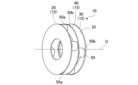
- FIG. 1 is a perspective view of a power transmission joint according to a first embodiment of the present disclosure.
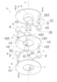
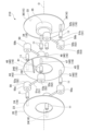
- FIG. 1 is an exploded perspective view of a power transmission joint according to a first embodiment of the present disclosure.
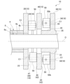
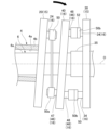
- FIG. 2 is an axial cross-sectional view of the power transmission joint according to the first embodiment of the present disclosure.
- FIG. 3 is a diagram illustrating absorption of vertical displacement and traveling displacement by the power transmission joint according to the first embodiment of the present disclosure.
- FIG. 3 is a diagram illustrating absorption of axial displacement by the power transmission joint according to the first embodiment of the present disclosure.
- FIG. 1 is a schematic configuration diagram of a truck according to a first embodiment of the present disclosure, viewed from a traveling direction.
- FIG. 1 is a perspective view of a power transmission joint according to a first embodiment of the present disclosure.
- FIG. 1 is an exploded perspective view
- FIG. 3 is a diagram illustrating absorption of an inclination angle by the power transmission joint according to the first embodiment of the present disclosure.
- FIG. 2 is an exploded perspective view of a power transmission joint according to a second embodiment of the present disclosure.
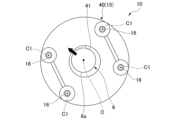
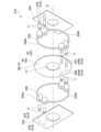
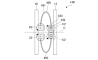
- FIG. 7 is an exploded perspective view of a power transmission joint according to a third embodiment of the present disclosure. It is a figure which shows typically the joint part of the power transmission joint based on 4th embodiment of this indication. It is a figure which shows typically the joint part of the power transmission joint based on 4th embodiment of this indication. It is a figure which shows typically the joint part of the power transmission joint based on the modification of the fourth embodiment of this indication. It is a figure which shows typically the joint part of the power transmission joint based on the modification of the fourth embodiment of this indication.
- a bogie 1 shown in FIG. 1 is a bogie for a railway vehicle.
- the truck 1 includes a truck frame 2, a motor 3, a drive shaft 4, an axle (driven shaft) 6, wheels 7, an axle spring 8, and a power transmission joint 10.
- the truck frame 2 is spaced upward from the rail L that runs along the ground.
- the bottom portion 2a of the truck frame 2 extends in the horizontal direction.
- the bottom portion 2a of the truck frame 2 extends in the longitudinal direction of the rail L.
- the motor 3 is a direct drive motor.
- the motor 3 is attached to the lower surface of the bottom portion 2a of the truck frame 2 via a motor suspension portion 5.
- the motor 3 has a rotor 3a.
- the rotor 3a is formed in a cylindrical shape extending in a horizontal direction and in a direction orthogonal to the longitudinal direction of the rail L.
- the drive shaft 4 is inserted through the rotor 3a.
- the drive shaft 4 is a hollow shaft formed in a cylindrical shape and extending in a horizontal direction and in a direction orthogonal to the longitudinal direction of the rail L.
- the outer peripheral surface 4b of the drive shaft 4 is fixed to the inner peripheral surface of the rotor 3a.
- the drive shaft 4 is driven by the motor 3 and rotates around the axis O of the drive shaft 4 .
- the drive shaft 4 is made of metal material.
- the axis O of the drive shaft 4 will be simply referred to as “axis O”
- the radial direction of axis O will be simply referred to as “radial direction”
- the circumferential direction of axis O will simply be referred to as “circumferential direction”.
- the direction of the axis O is perpendicular to the longitudinal direction of the rail L.
- One end of the drive shaft 4 in the direction of the axis O is located outside the rotor 3a in the direction of the axis O.
- the axle 6 is formed into a cylindrical shape.
- the axle 6 is made of metal material.
- the axle 6 is inserted through the drive shaft 4.
- the motor 3 is located at an intermediate portion of the axle 6 in the direction of the axis O. That is, the axle 6 is arranged coaxially with the drive shaft 4. At least a portion of the axle 6 is arranged at a position spaced apart from the drive shaft 4 in the direction of the axis O of the drive shaft 4 .
- the middle portion of the axle 6 in the direction of the axis O is arranged at a position overlapping the drive shaft 4 in the radial direction, and both ends of the axle 6 in the direction of the axis O are arranged at positions spaced apart from the drive shaft 4 in the direction of the axis O. has been done.
- the axle 6 is arranged so as to be spaced apart from the inner peripheral surface 4a of the drive shaft 4. Torque around the axis O is transmitted from the motor 3 to the axle 6 via the drive shaft 4 and the power transmission joint 10 .
- the axle 6 rotates around the axis O by the torque of the motor 3.
- a pair of wheels 7 facing each other in the axis O direction are provided at both ends of the axle 6 in the axis O direction.
- An axial spring 8 is provided between the axle 6 and the truck frame 2. (There is a bearing and a bearing box on the lower side of the shaft spring 8 (on the axle 6 side), but they are not shown.)
- the wheel 7 is arranged at a position spaced apart from the motor 3 in the direction of the axis O.
- the wheel 7 is formed into a disc shape.
- the thickness direction of the wheel 7 coincides with the axis O direction.
- the wheel 7 is connected to the end of the axle 6 at its center. Wheel 7 is fixed to axle 6.
- Each wheel 7 is in contact with the rail L at its lower end. The wheels 7 rotate on the rails L by the torque transmitted from the axle 6.
- the shaft spring 8 absorbs vibrations in the vertical direction.
- the shaft spring 8 is provided at a position close to the wheel 7.
- the shaft spring 8 is a coil spring that extends in the vertical direction.
- the upper end of the shaft spring 8 is fixed to the bottom 2a of the truck frame 2.
- the lower end of the shaft spring 8 is connected to the axle 6 via a connecting member (not shown).
- the shaft spring 8 is provided so that the torque of the motor 3 is not transmitted from the axle 6 through this connecting member.
- a pair of shaft springs 8 are provided on both outer sides of the motor 3 in the direction of the axis O.
- a power transmission joint 10 is provided between one of the pair of shaft springs 8 and the motor 3 .
- the power transmission joint 10 transmits the torque of the motor 3 to the axle 6.
- the power transmission joint 10 is provided between the motor 3 and the wheels 7. As shown in FIGS. 2 to 4, the power transmission joint 10 includes a joint member 15, an elastic body 50, and a joint portion 16.
- the joint member 15 is provided between the motor 3 and the wheel 7.
- the joint members 15 are arranged at equal intervals in the direction of the axis O.
- the joint member 15 includes a motor-side joint 20, an axle-side joint (driven shaft-side joint) 30, and an intermediate body 40.
- the motor side joint 20 is provided between the motor 3 and the wheel 7.
- the motor side joint 20 is fixed to the drive shaft 4 of the motor 3. More specifically, the motor-side joint 20 is provided at the end of the drive shaft 4 in the direction of the axis O, and is integrated with the drive shaft 4 .
- the motor side joint 20 is formed in a flange shape that covers the axle 6 from the outer circumferential side.
- the plate thickness direction of the motor side joint 20 intersects with the radial direction. In this embodiment, the plate thickness direction of the motor side joint 20 is perpendicular to the radial direction. That is, the plate thickness direction of the motor side joint 20 coincides with the axis O direction.
- the motor side joint 20 is formed into a plate shape with a constant thickness in the radial direction and the circumferential direction.
- the motor side joint 20 is formed of a metal material.
- the inner diameter of the motor side joint 20 is larger than the outer diameter of the axle 6. Therefore, the motor-side joint 20 is movable relative to the axle 6 in the axis O direction and in the radial direction.
- the outer diameter of the motor-side joint 20 is larger than the outer diameter of the drive shaft 4.
- An axle-side joint 30 is provided between the motor-side joint 20 and the wheel 7.
- the axle-side joint 30 is provided on the opposite side of the motor 3 with the motor-side joint 20 interposed therebetween. That is, the axle-side joint 30 faces the motor-side joint 20 in the axis O direction.
- the axle-side joint 30 is formed in a flange shape that covers the axle 6 from the outer peripheral side.
- the plate thickness direction of the axle-side joint 30 intersects with the radial direction. In this embodiment, the plate thickness direction of the axle-side joint 30 is perpendicular to the radial direction. That is, the plate thickness direction of the axle-side joint 30 coincides with the axis O direction.
- the axle side joint 30 is arranged parallel to the motor side joint 20.
- the axle-side joint 30 is formed into a plate shape with constant plate thickness in the radial direction and the circumferential direction.
- the axle side joint 30 is formed of a metal material.
- fixed cylinders 35 are provided on two surfaces of the axle-side joint 30 facing the axis O direction.
- the fixed cylinder 35 is provided at a radially inner portion of the axle-side joint 30.
- the fixed cylinder 35 is formed into a cylindrical shape extending in the direction of the axis O.
- the inner circumferential surface of the fixed cylinder 35 is flush with the inner circumferential surface of the axle-side joint 30.
- the fixed tube 35 provided on the side surface 33 facing the motor 3 side in the direction of the axis O is longer in the direction of the axis O than the fixed tube 35 on the opposite side.
- the axle-side joint 30 is press-fitted and fixed to the outer circumferential surface 6a of the axle 6 in a stable state by a fixed tube 35.
- An intermediate body 40 is provided between the axle side joint 30 and the motor side joint 20.
- the intermediate body 40 is formed in a flange shape that covers the axle 6 from the outer peripheral side.
- the thickness direction of the intermediate body 40 intersects with the radial direction.
- the thickness direction of the intermediate body 40 is perpendicular to the radial direction. That is, the thickness direction of the intermediate body 40 coincides with the direction of the axis O.
- the intermediate body 40 is formed into a plate shape having a constant thickness in the radial direction and the circumferential direction.
- Intermediate body 40 is formed of a metal material.
- the inner peripheral surface 41 of the intermediate body 40 is further away from the outer peripheral surface 6a of the axle 6 in the radial direction than the inner peripheral surface of the motor-side joint 20.
- a pair of side surfaces 43 of the intermediate body 40 facing in the direction of the axis O are each provided with an intermediate joint portion 46 .
- the side surface 43 facing the motor 3 side in the axis O direction will be referred to as the "first side surface 44”
- the side surface 43 facing the wheel 7 side in the axis line O direction will be referred to as the "second side surface 45”. to be called.
- a plurality of elastic bodies 50 are provided between joint members 15 adjacent to each other in the axis O direction.
- the elastic body 50 connects the joint members 15 aligned in the direction of the axis O.
- the elastic body 50 is illustrated abstractly. That is, in the drawing, both ends of the elastic body 50 are illustrated as cylindrical members, and both ends of the elastic body 50 are connected by thick lines. Details of characteristics such as the shape and material of the elastic body 50 will be described in text.
- the elastic body 50 is formed into a plate shape extending in a direction intersecting the axis O direction. In this embodiment, the elastic body 50 is formed in a straight line that intersects with the axis O direction.
- the elastic body 50 is a so-called leaf spring made of a metal material.
- the thickness direction of the elastic body 50 intersects with the radial direction.
- a plurality of elastic bodies 50 are provided at symmetrical positions with respect to the axis O direction in the gaps between the joint members 15 adjacent to each other in the axis O direction.
- a pair of elastic bodies 50 are provided facing each other in the radial direction.
- the pair of elastic bodies 50 are arranged symmetrically about the axis O.
- the elastic bodies 50 that are adjacent to each other in the direction of the axis O are rotated about the axis O and arranged so that their phases are different from each other.
- the elastic bodies 50 that are adjacent to each other in the direction of the axis O are rotated about the axis O within a range of 85 degrees or more and 95 degrees or less, and are arranged so that their phases differ from each other. More specifically, the elastic bodies 50 that are adjacent to each other in the direction of the axis O are arranged so as to be rotated by 90 degrees about the axis O.
- Each elastic body 50 has an elastic main body portion 51 and a joint end 52 .
- the elastic main body portion 51 is a portion of the elastic body 50 other than both ends.
- the plate thickness of the elastic main body portion 51 is constant in the axis O direction and the circumferential direction.
- the joint ends 52 are both ends of the elastic body 50.
- the joint end 52 is formed thicker than the elastic main body portion 51.
- the joint end 52 is curved into an arc shape when viewed from the direction of the axis O.
- a joining hole 53 penetrating in the direction of the axis O is formed in the joining end 52 .
- the plurality of elastic bodies 50 include a motor-side elastic body 50a and an axle-side elastic body 50b.
- the motor-side elastic body 50a is provided between the intermediate body 40 and the motor-side joint 20.
- the motor side elastic body 50a connects the motor side joint 20 and the intermediate body 40.
- the elastic body 51 of the motor side elastic body 50a will be referred to as the "motor side elastic body 51a”
- the joint end 52 of the motor side elastic body 50a will be referred to as the “motor side joint end 52a”
- the motor side elastic body 50a will be referred to as the joint end 52 of the motor side elastic body 50a.
- the joining hole 53 may be referred to as a "motor side joining hole 53a.”
- the axle-side elastic body 50b is provided between the axle-side joint 30 and the intermediate body 40.
- the axle-side elastic body 50b connects the axle-side joint 30 and the intermediate body 40.
- the elastic body 51 of the axle-side elastic body 50b will be referred to as the "axle-side elastic body 51b”
- the joint end 52 of the axle-side elastic body 50b will be referred to as the "axle-side joint end 52b”
- the axle-side elastic body 50b will be referred to as the joint end 52 of the axle-side elastic body 50b.
- the joining hole 53 may be referred to as the "axle side joining hole 53b".
- each joint portion 16 is provided in a fixed state to each joint member 15. That is, the joint portion 16 is provided in each of the motor-side joint 20, the axle-side joint 30, and the intermediate body 40. In this embodiment, each joint member 15 is provided with a plurality of joint portions 16 .
- the joint portion 16 is a cylindrical pin that protrudes from the joint member 15 in the direction of the axis O.
- the joint portion 16 is integrated with the joint member 15 by, for example, welding.
- the joint portion 16 joins both ends of the elastic body 50. That is, the joint portion 16 joins with the joint end 52 of the elastic body 50.
- the joint portion 16 is inserted into the joint hole 53 of the joint end 52 via the rubber bush 11 .
- both ends of the elastic body 50 are joined to be rotatable around the link axis C1 that passes through the joint 16 and extends in the direction of the axis O. There is.
- the plurality of joints 16 include a motor side joint 24 , an axle side joint 34 , and an intermediate body joint 46 .
- the motor-side joint portion 24 is provided at the motor-side joint 20 . More specifically, the motor-side joint portion 24 is provided on the side surface 23 of the motor-side joint 20 facing away from the motor 3 in the axis O direction. Two motor-side joints 24 are provided on the same virtual arc centered on the axis O and at positions spaced apart from each other in the circumferential direction with a predetermined phase difference.
- phase means “circumferential phase”
- circumferential phase means “circumferential position”.
- a and B are spaced apart in the circumferential direction
- a central axis such as axis O or a center point is simply the “center”
- a half straight line connecting the center and A, and a half line between the center and B This means that the angle formed by the half line connecting the two is, for example, 45 degrees or more.
- the angle formed by the half-line connecting the center and A and the half-line connecting the center and B may simply be referred to as the "center angle” between A and B.
- the central angle of the two motor-side joints 24 is about 90 degrees.
- the motor-side joint 24 is made of the same metal material as the motor-side joint 20.
- the motor-side joint portion 24 is inserted into the motor-side joint hole 53a of one of the two motor-side joint ends 52a of the motor-side elastic body 50a.
- the motor-side joint portion 24 is joined to the one motor-side joint end 52a.
- the axle-side joint portion 34 is provided at the axle-side joint 30. More specifically, the axle-side joint portion 34 is provided on the side surface 33 of the axle-side joint 30 facing away from the wheel 7 in the axis O direction.
- Two axle-side joints 34 are provided on the same virtual arc centered on the axis O and at positions spaced apart from each other in the circumferential direction with a predetermined phase difference.
- the radius of the virtual arc passing through the two axle-side joints 34 is equal to the radius of the virtual arc passing through the two motor-side joints 24.
- the center angle of the two axle-side joints 34 is equal to the center angle of the two motor-side joints 24, and is about 90 degrees.
- the axle-side joint 34 is made of the same metal material as the axle-side joint 30.
- the axle-side joint portion 34 is inserted into the axle-side joint hole 53b of one of the two axle-side joint ends 52b of the axle-side elastic body 50b.
- the axle-side joint portion 34 is joined to the one axle-side joint end 52b.
- the axle-side joint 30 is arranged so that the axle-side joint 34 and the motor-side joint 24 are in different circumferential phases with respect to the motor-side joint 20 .
- the overall phase difference between the two axle-side joints 34 and the two motor-side joints 24 is 90 degrees.
- the "phase difference” is expressed as an angle in the circumferential direction around the axis O. The same applies to "phase difference” below.
- a plurality of intermediate body joining parts 46 are provided in the intermediate body 40.
- the plurality of intermediate joints 46 include a first intermediate joint 47 on the motor 3 side and a second intermediate joint 48 on the wheel 7 side.
- the first intermediate joint portion 47 is provided on the first side surface 44 .
- Two first intermediate joints 47 are provided on the same virtual arc centered on the axis O and at positions spaced apart from each other in the circumferential direction with a predetermined phase difference.
- the radius of the virtual arc passing through the two first intermediate joints 47 is equal to the radius of the virtual arc passing through the two motor-side joints 24 and the radius of the virtual arc passing through the two axle-side joints 34 .
- the central angle of the two first intermediate joints 47 is equal to the central angle of the two motor-side joints 24 and the central angle of the two axle-side joints 34, and is about 90 degrees.
- the first intermediate body joining portion 47 is formed of the same metal material as the intermediate body 40.
- the first intermediate joint portion 47 is inserted into the motor-side joint hole 53a of the other motor-side joint end 52a that is not joined to the motor-side joint portion 24 among the two motor-side joint ends 52a of the motor-side elastic body 50a. .
- the first intermediate joint portion 47 is joined to the other motor side joint end 52a.
- the second intermediate joint portion 48 is provided on the second side surface 45.
- Two second intermediate joints 48 are provided on the same virtual arc centered on the axis O and at positions spaced apart from each other in the circumferential direction with a predetermined phase difference.
- the radius of the virtual arc passing through the two second intermediate joints 48 is equal to the radius of the virtual arc passing through the two first intermediate joints 47.
- the central angle of the two second intermediate joints 48 is equal to the central angle of the two first intermediate joints 47, and is about 90 degrees.
- the two second intermediate joints 48 are provided out of phase with respect to the two first intermediate joints 47 in the circumferential direction.
- the overall phase difference between the two second intermediate joints 48 and the two first intermediate joints 47 is 90 degrees.
- the second intermediate joint portion 48 is made of the same metal material as the intermediate body 40.
- the second intermediate joint portion 48 is inserted into the axle-side joint hole 53b of the other axle-side joint end 52b that is not joined to the axle-side joint portion 34 among the two axle-side joint ends 52b of the axle-side elastic body 50b. .
- the second intermediate joint portion 48 is joined to the other axle-side joint end 52b.
- the intermediate bodies 40 are arranged differently from each other with respect to the motor side joint 20 so that the motor side joint part 24 and the first intermediate body joint part 47 have different circumferential phases.
- the overall phase difference between the two first intermediate joints 47 and the two motor side joints 24 is 180 degrees.
- the intermediate bodies 40 are arranged differently from each other with respect to the axle-side joint 30 so that the axle-side joint portion 34 and the second intermediate body joint portion 48 have different circumferential phases.
- the overall phase difference between the two second intermediate joints 48 and the two axle-side joints 34 is 180 degrees.
- the motor side joint part 24, the axle side joint part 34, the first intermediate body joint part 47, and the second intermediate body joint part 48 are They are arranged at positions shifted by 90 degrees around the axis O.
- the elastic bodies 50 adjacent to each other in the direction of the axis O are arranged so as to be rotated by 90 degrees about the axis O. That is, the motor-side elastic body 50a and the axle-side elastic body 50b are arranged to have different phases in the circumferential direction, and the overall phase difference between the pair of motor-side elastic bodies 50a and the pair of axle-side elastic bodies 50b is is 90 degrees.
- at least one of the motor-side elastic body 50a and the axle-side elastic body 50b is arranged at all circumferential positions of the power transmission joint 10.
- the power transmission joint 10 constitutes a link mechanism as a whole by the elastic body 50 that is rotatable (free to rotate) around the joint portion 16.
- the power transmission joint 10 constitutes a link mechanism including an elastic body 50 that is rotatable (free to rotate) around the joint portion 16 . Therefore, the power transmission joint 10 transmits torque without substantially elastically deforming the elastic body 50 in the radial direction.
- each elastic body 50 rotates around the joint portion 16, and the intermediate body 40 is displaced in the radial direction (in-plane displacement). Thereby, vertical displacement of the axle 6 is absorbed.
- the axle 6 may be displaced in the direction of the axis O as shown in FIG. 6 due to the weight of the wheel 7, vibration, etc. of the truck 1.
- the direction of displacement in the direction of the axis O is indicated by an arrow.
- the elastic body 50 is elastically deformed in the direction of the axis O (out-of-plane deformation).
- an elastic force acts in a direction opposite to the direction of displacement. This elastic force suppresses displacement in the direction of the axis O. In this way, displacement of the axle 6 in the direction of the axis O is absorbed.
- the motor side joint 20 is tilted with respect to the axle side joint 30, as shown in FIG. A tilt angle may occur with respect to the axis of rotation.
- the direction of the inclination angle of the motor side joint 20 is indicated by an arrow.
- the intermediate body 40 and the elastic body 50 are tilted similarly to the motor-side joint 20, and the elastic body 50 is elastically deformed in the direction of the axis O (out-of-plane deformation).
- an elastic force acts in a direction opposite to the inclination of the motor-side joint 20.
- This elastic force suppresses the inclination of the motor side joint 20. In this way, the angle of inclination between the motor-side joint 20 and the axle-side joint 30 is absorbed.
- the power transmission joint 10 is provided between joint members 15 arranged in the axis O direction and between joint members 15 adjacent in the axis O direction, and connects the joint members 15 adjacent in the axis O direction. It also includes a plurality of plate-shaped elastic bodies 50 extending in a direction intersecting the axis O direction, and a plurality of joint parts 16 provided on each joint member 15 and joined to both ends of the elastic bodies 50.
- the joint member 15 includes a motor-side joint 20 fixed to the drive shaft 4, and an axle joint 20 fixed to the outer circumferential surface 6a of the axle 6, which is provided on the opposite side of the motor 3 in the axis O direction across the motor-side joint 20.
- Both ends of the elastic body 50 are joined to be rotatable around a link axis C1 that passes through the joint 16 and extends in the direction of the axis O.
- the power transmission joint 10 transmits the torque of the motor 3 as a couple.
- the power transmission joint 10 can function as a link mechanism. That is, the power transmission joint 10 can move like a link in response to forced displacement in a plane perpendicular to the axis O direction. Therefore, no resistance is generated against forced displacement within the plane. Thereby, the power transmission joint 10 can satisfactorily transmit the torque of the motor 3.
- the intermediate body 40 is arranged between the elastic bodies 50. Therefore, a plurality of elastic bodies 50 can be arranged in series in the axis O direction. Thereby, the power transmission joint 10 can extend the elastic body 50 in the direction of the axis O and reduce the rigidity in the direction of the axis O while there is a radial dimension restriction.
- each elastic body 50 can be set to any shape. That is, by arranging the elastic bodies 50 in series while making the elastic bodies 50 have a shape capable of resisting torque, it is possible to realize the power transmission joint 10 with low rigidity. Furthermore, the power transmission joint 10 can also exhibit a so-called vibration isolation function by causing frictional damping by the plurality of elastic bodies 50 arranged in series.
- the thickness direction of the elastic body 50 intersects with the radial direction.
- the rigidity of the elastic body 50 in the axis O direction is smaller than the rigidity in the radial direction. Therefore, as a link mechanism, the power transmission joint 10 easily absorbs displacement in the direction perpendicular to the axis, and also easily absorbs displacement in the axial direction due to the deformation of the elastic body 50 in the direction of the axis O. In this way, since the rigidity of the elastic body 50 can be reduced, the power transmission joint 10 can satisfactorily absorb the displacement of the axle 6.
- the power transmission joint 10 includes a joint member 15, an elastic body 50, and a joint portion 16.
- the power transmission joint 10 can suppress torque attenuation during the process in which the torque of the motor 3 is transmitted to the axle 6. Therefore, the power transmission joint 10 can satisfactorily transmit the torque of the motor 3 to the axle 6 while absorbing the displacement of the axle 6 well. Therefore, even when the displacement of the axle 6 is large, the large displacement of the axle 6 can be absorbed sufficiently well.
- the power transmission joint 10 can sufficiently transmit the high rotational speed of the motor 3 to the axle shaft 6. Furthermore, the power transmission joint 10 can be made into a compact mechanism. In this way, the power transmission joint 10 is a mechanism that is more compact than the conventional one, and can transmit the large torque and high rotation of the motor 3 to the axle 6 while absorbing large displacements of the axle 6.
- the power transmission joint 10 can absorb large displacements and can achieve large torque and high rotation transmission of the motor 3. Therefore, it becomes possible to configure a so-called direct drive mechanism.
- the motor/gear weight ratio, unsprung weight ratio, and truck 1 frame weight ratio are all lower than in the conventional case. can also be reduced.
- the elastic body 50 is formed in a straight line that intersects with the axis O direction.
- the couple generated at both ends of the elastic body 50 by the torque of the motor 3 is transmitted by axial force. Therefore, when the torque is relatively large, the power transmission joint 10 can efficiently transmit the couple and can efficiently transmit the torque of the motor 3 to the axle.
- the elastic body 50 is connected to the joint portion 16 of the joint member 15 via the rubber bush 11, but the present invention is not limited to this.
- the rubber bush 11 may not be used for joining.
- the end face of each joint may be a so-called spherical seat.
- a slit 241 is formed in the intermediate body 240.
- the slit 241 is provided on the opposite side of the intermediate body joining portion 46 in the radial direction with respect to the axis O.
- the slit 241 is formed to penetrate into the interior of the intermediate body 240 from the edge thereof.
- the slit 241 is formed in a straight line when viewed from the axis O direction.
- the slit 241 passes through the intermediate body 240 in the axial direction.
- a slit 241 is formed in the intermediate body 240.
- the rigidity of the intermediate body 240 can be reduced. This makes it easier for the intermediate body 240 to deform in the direction of the axis O. Therefore, the power transmission joint 210 can relieve stress against forced displacement.
- the motor-side joint 320 is formed into a rectangular plate shape whose thickness direction intersects with the radial direction.
- the motor side joint 320 extends in one direction when viewed from the axis O direction.
- An insertion hole into which the axle 6 is inserted is formed in the center of the motor side joint 320.
- the inner circumferential surface of the insertion hole is spaced radially outward from the outer circumferential surface 6a of the axle 6.
- the axle-side joint 330 is formed into a rectangular plate shape whose thickness direction intersects with the radial direction.
- the axle-side joint 330 extends in one direction when viewed from the axis O direction.
- the axle-side joint 330 is arranged with a circumferential phase shift of 90 degrees with respect to the motor-side joint 320. That is, when viewed from the direction of the axis O, the longitudinal direction of the axle-side joint 330 is orthogonal to the longitudinal direction of the motor-side joint 320.
- the elastic body 350 is curved when viewed from the axis O direction. More specifically, the elastic body 350 is formed in an arc shape extending in the circumferential direction when viewed from the axis O direction. Note that in this embodiment, the elastic body 350 is illustrated abstractly as in the first embodiment.
- the plurality of joints 316 are provided at different positions from those in the first embodiment.
- the plurality of joints 316 include a motor-side joint 324, an axle-side joint 334, and an intermediate joint 346.
- the motor-side joint portions 324 are provided in a pair at one longitudinal end of the motor-side joint 320 so as to be adjacent to each other in the circumferential direction and in the same phase.
- two motor-side joints 324 are provided on the same virtual arc centered on the axis O and at positions close to each other in the circumferential direction.
- the axle-side joint portions 334 are provided in a pair at one longitudinal end of the axle-side joint 330 so as to be adjacent to each other in the circumferential direction and in the same phase.
- two axle-side joints 334 are provided on the same virtual arc centered on the axis O and at positions close to each other in the circumferential direction.
- the radius of the virtual arc passing through the two axle-side joints 334 is equal to the radius of the virtual arc passing through the two motor-side joints 324.
- the central angle of the two axle-side joints 334 is equal to the central angle of the two motor-side joints 324.
- the plurality of intermediate joints 346 include a first intermediate joint 347 and a second intermediate joint 348.
- the first intermediate joint portions 347 are provided as a pair in the same phase so as to be adjacent to each other in the circumferential direction.
- two first intermediate joints 347 are provided on the same virtual arc centered on the axis O and at positions close to each other in the circumferential direction.
- the radius of the virtual arc passing through the two first intermediate joints 347 is equal to the radius of the virtual arc passing through the two motor-side joints 324 and the radius of the virtual arc passing through the two axle-side joints 334.
- the central angle of the two first intermediate joints 347 is equal to the central angle of the two motor-side joints 324 and the central angle of the two axle-side joints 334.
- the second intermediate joint portions 348 are provided as a pair in the same phase so as to be adjacent to each other in the circumferential direction.
- two second intermediate joints 348 are provided on the same virtual arc centered on the axis O and at positions close to each other in the circumferential direction.
- the radius of the virtual arc passing through the two second intermediate joints 348 is equal to the radius of the virtual arc passing through the two first intermediate joints 347.
- the central angle of the two second intermediate joints 348 is equal to the central angle of the two first intermediate joints 347.
- the two second intermediate joints 348 are provided with a phase shift in the circumferential direction with respect to the two first intermediate joints 347.
- the overall phase difference between the two second intermediate joints 348 and the two first intermediate joints 347 is 90 degrees.
- the intermediate bodies 40 are arranged differently from each other with respect to the motor side joint 320 so that the motor side joint portion 324 and the first intermediate body joint portion 347 have different circumferential phases.
- the overall phase difference between the two first intermediate joints 47 and the two motor side joints 324 is 180 degrees.
- the intermediate bodies 40 are arranged differently from each other with respect to the axle-side joint 330 so that the axle-side joint portion 334 and the second intermediate body joint portion 348 have different circumferential phases.
- the overall phase difference between the two second intermediate joints 348 and the two axle-side joints 334 is 180 degrees.
- the motor side joint part 324, the axle side joint part 334, the first intermediate body joint part 347, and the second intermediate body joint part 348 are They are arranged at positions shifted by 90 degrees around the axis O.
- the elastic bodies 350 that are adjacent to each other in the direction of the axis O are arranged so as to be rotated by 90 degrees about the axis O. That is, the motor-side elastic body 350a and the axle-side elastic body 350b are arranged to have different phases in the circumferential direction, and the overall phase difference between the pair of motor-side elastic bodies 350a and the pair of axle-side elastic bodies 350b is is 90 degrees.
- at least one of the motor-side elastic body 350a and the axle-side elastic body 350b is arranged at all circumferential positions of the power transmission joint 10.
- the elastic body 350 is curved when viewed from the axis O direction.
- the couple generated at both ends of the elastic body 350 by the torque of the motor 3 is transmitted by bending the elastic body 350. Therefore, the power transmission joint 310 can reduce the risk of buckling of the elastic body 350, which is a concern when a couple is transmitted by axial force. Furthermore, the length of the elastic body 350 becomes longer than when the elastic body 350 is formed in a straight line. Therefore, the power transmission joint 310 can reduce the rigidity of the elastic body 350.
- both ends of the elastic body 450 are rotatably joined around a joint axis C2 that passes through the joint 416 and extends in a direction perpendicular to the axis O direction.
- the elastic body 450 is illustrated abstractly as in the first embodiment.
- the elastic body 450 has an elastic main body portion 451 and a joining end 452.
- a joining hole 453 is provided in the joining end 452 .
- the joining hole 453 of this embodiment penetrates the joining end 452 in the plate thickness direction.
- the joint portion 416 itself is rotatable around the link axis C1 extending in the axis O direction.
- the joint portion 416 includes a plate portion 416a and a shaft portion 416b.
- the plate portion 416a is a plate-shaped member that protrudes from the joint member 15 in the direction of the axis O.
- a pair of plate portions 416a are provided for each joint portion 416 so as to face each other in the direction of the straight line connecting the pair of joint ends 452. Further, the pair of plate portions 416a are provided so as to be rotatable as a unit around the link axis C1. The pair of plate portions 416a sandwich the joint end 452 of the elastic body 450.
- the shaft portion 416b is provided between the pair of plate portions 416a, and connects the pair of plate portions 416a.
- the shaft portion 416b extends in the direction of a straight line connecting the pair of joint ends 452.
- the shaft portion 416b is inserted into the joining hole 453 of the joining end 452.
- Both ends of the elastic body 450 are rotatably joined around the shaft portion 416b of the joint portion 416. That is, in this embodiment, the joint axis C2 extends along the center line of the joint 416 in the direction of a straight line connecting the pair of joint ends 452.
- both ends of the elastic body 450 pass through the joint 416 and are joined to be rotatable around the joint axis C2.
- the elastic body 450 rotates around the joint axis C2. This allows the power transmission joint 410 to release displacement in the axis O direction.
- each joint end 452 extends in the direction of a straight line connecting the pair of joint ends 452 and away from the other joint ends 452 .
- one plate portion 416a is provided for each joint portion 416.
- the plate portion 416a is overlapped with the joint end 452 from the circumferential direction.
- the shaft portion 416b protrudes from the plate portion 416a in a direction perpendicular to the axis O direction and in a direction perpendicular to the straight line connecting the pair of joint ends 452.
- the shaft portion 416b is inserted into the joining hole 453 of the joining end 452.
- Both ends of the elastic body 1150 are rotatably joined around the shaft portion 416b of the joint portion 416. That is, in this modification, the joint axis C2 extends along the center line of the joint 416 in a direction perpendicular to the axis O direction and perpendicular to the direction of the straight line connecting the pair of joint ends 452. There is.
- the elastic body 450 and the joint 416 may be rotatably joined around the joint axis C2 by, for example, a hinge or a spherical seat.
- both ends of the elastic body 450 are rotatably joined around the joint axis C2
- the present invention is not limited to this. Only one of both ends of the elastic body 450 may be rotatably joined around the joint axis C2.
- the drive shaft 4 is a hollow shaft, but the drive shaft 4 is not limited to this.
- the drive shaft 4 may be, for example, a solid shaft formed in a cylindrical shape.
- the entire axle (driven shaft) 6 is arranged at a position spaced apart from the drive shaft 4 in the direction of the axis O.
- bogie 1 is a railway vehicle trolley
- the trolley 1 may be used, for example, as a forklift or an electrically assisted trolley that is manually pushed by a person when transporting a heavy object.
- the power transmission joints 10, 210, 310, 410 may be used for applications other than bogies.
- the power transmission joints 10, 210, 310, and 410 include a drive shaft 4 that rotates under the drive of a motor 3 having a rotor 3a, and an axis line from the drive shaft 4 to the drive shaft 4.
- a drive shaft 4 that rotates under the drive of a motor 3 having a rotor 3a
- an axis line from the drive shaft 4 to the drive shaft 4.
- joint members 15 aligned in the axis O direction and adjacent in the axis O direction
- a plurality of plate-shaped elastic bodies 50, 350, 450 are provided between the joint members 15 to connect the joint members 15 adjacent to each other in the direction of the axis O, and extend in a direction intersecting the direction of the axis O.
- a joint, and an intermediate body 40, 240 provided between the motor side joint 20, 320 and the driven shaft side joint, and both ends of the elastic body 50, 350, 450 are connected to the joint part 16.
- 316, 416 is rotatably joined around a link axis C1 extending in the direction of the axis O.
- An example of the driven shaft is the axle 6.
- Examples of driven shaft side joints include axle side joints 30 and 330.
- the power transmission joints 10, 210, 310, and 410 transmit the torque of the motor 3 as a couple.
- the power transmission joints 10, 210, 310, 410 can function as link mechanisms. That is, the power transmission joints 10, 210, 310, and 410 can move like links in response to forced displacement in a plane perpendicular to the axis O direction.
- intermediate bodies 40, 240 are arranged between elastic bodies 50, 350, 450. Therefore, a plurality of elastic bodies 50, 350, 450 can be arranged in series in the axis O direction. Further, since the plurality of elastic bodies 50, 350, 450 are arranged in series in the direction of the axis O, each elastic body 50, 350, 450 can be set in any shape.
- the power transmission joint 210 of the second embodiment is the power transmission joint 210 of the first embodiment, and the intermediate body 240 may have a slit 241 formed therein.
- the rigidity of the intermediate body 240 can be reduced.
- the power transmission joint 410 of the third aspect is the power transmission joint 410 of the first or second aspect, in which at least one of both ends of the elastic body 450 passes through the joint portion 416 and
- the joint may be rotatably joined around a joint axis C2 extending in a direction perpendicular to the axis O direction.
- the elastic body 450 rotates around the joint axis C2.
- the power transmission joint 10 of the fourth aspect is any one of the first to third power transmission joints 10, in which the elastic body 50 is formed in a linear shape intersecting the axis O direction. You can leave it there.
- the couple generated at both ends of the elastic body 50 by the torque of the motor 3 is transmitted by the axial force.
- the power transmission joint 310 of the fifth aspect is any one of the first to third power transmission joints 310, and the elastic body 350 is curved when viewed from the axis O direction. Good too.
- the couple generated at both ends of the elastic body 350 by the torque of the motor 3 is transmitted by bending the elastic body 350. Furthermore, the length of the elastic body 350 becomes longer than when the elastic body 350 is formed in a straight line.
- the power transmission joint of the present disclosure it is possible to satisfactorily absorb the displacement of the driven shaft while transmitting the torque of the motor to the driven shaft.
- Axial spring 10 ...Power transmission joint 11...Rubber bush 15...Joint member 16...Joint part 20...Motor side joint 23...Side surface 24...Motor side joint part 30...Axle side joint (driven shaft side joint) 33...Side surface 34...Axle Side joint 35...Fixed tube 40...Intermediate body 41...Inner circumferential surface 42...Outer circumferential surface 43...Side surface 44...First side 45...Second side 46...Intermediate body joint 47...First intermediate body joint 48...Second side Two intermediate body joining part 50...Elastic body 50a...Motor side elastic body 50b...Axle side elastic body 51...Elastic main body part 51a...Motor side elastic main body part 51b...Axle side elastic main body part 52...Joint end 52a...Motor side joint end 52b...Axle side joining end 53...Joining hole 53a...Motor side joining hole 53b...Axle side joining hole 210
Landscapes
- Engineering & Computer Science (AREA)
- General Engineering & Computer Science (AREA)
- Mechanical Engineering (AREA)
- Arrangement Or Mounting Of Propulsion Units For Vehicles (AREA)
Abstract
動力伝達継手は、軸線方向に並ぶ継手部材と、軸線方向で隣り合う継手部材同士の間に設けられて軸線方向で隣り合う継手部材同士を連結するとともに、軸線方向に交差する方向に延びる板状の複数の弾性体と、各継手部材に設けられ、弾性体の両端部と接合する複数の接合部と、を備え、継手部材は、駆動軸に固定されるモータ側継手と、モータ側継手を挟んで軸線方向でモータとは反対側に設けられ、従動軸の外周面に固定される従動軸側継手と、モータ側継手と従動軸側継手との間に設けられた中間体と、を含み、弾性体の両端部は、接合部を通るとともに軸線方向に延びるリンク軸線回りに回転可能に接合されている。
Description
本開示は、動力伝達継手に関する。
本願は、2022年3月22日に日本に出願された特願2022-045963号について優先権を主張し、その内容をここに援用する。
本願は、2022年3月22日に日本に出願された特願2022-045963号について優先権を主張し、その内容をここに援用する。
特許文献1には、カルダン方式の鉄道車両用台車が開示されている。特許文献1の台車では、主電動機(モータ)の主電動機軸と車軸(従動軸)とが、歯車継手装置及び減速用の歯車装置を介して接続されている。モータのトルクは、主電動機軸、歯車継手装置及び歯車装置を介して従動軸に伝達される。
しかしながら、特許文献1の台車では、複数の歯車を介してトルク伝達を行うため、モータのトルクを従動軸に良好に伝達できない場合があった。
本開示は、上記課題を解決するためになされたものであって、従動軸の変位を良好に吸収しつつ、モータのトルクを従動軸に良好に伝達することができる動力伝達継手を提供することを目的とする。
上記課題を解決するために、本開示に係る動力伝達継手は、ロータを有するモータの駆動を受けて回転する駆動軸と、前記駆動軸から前記駆動軸の軸線方向に離間した位置に少なくとも一部が配置される従動軸とを接続する動力伝達継手において、前記軸線方向に並ぶ継手部材と、前記軸線方向で隣り合う前記継手部材同士の間に設けられて前記軸線方向で隣り合う前記継手部材同士を連結するとともに、前記軸線方向に交差する方向に延びる板状の複数の弾性体と、各前記継手部材に設けられ、前記弾性体の両端部と接合する複数の接合部と、を備え、前記継手部材は、前記駆動軸に固定されるモータ側継手と、前記モータ側継手を挟んで前記軸線方向で前記モータとは反対側に設けられ、前記従動軸の外周面に固定される従動軸側継手と、前記モータ側継手と前記従動軸側継手との間に設けられた中間体と、を含み、前記弾性体の両端部は、前記接合部を通るとともに前記軸線方向に延びるリンク軸線回りに回転可能に接合されている。
本開示の動力伝達継手によれば、従動軸の変位を良好に吸収しつつ、モータのトルクを従動軸に良好に伝達することができる。
<第一実施形態>
以下、本開示の第一実施形態に係る動力伝達継手10について、図1から図7を参照して説明する。
以下、本開示の第一実施形態に係る動力伝達継手10について、図1から図7を参照して説明する。
(台車)
図1に示す台車1は、鉄道車両用台車である。台車1は、台車フレーム2と、モータ3と、駆動軸4と、車軸(従動軸)6と、車輪7と、軸ばね8と、動力伝達継手10と、を備える。
図1に示す台車1は、鉄道車両用台車である。台車1は、台車フレーム2と、モータ3と、駆動軸4と、車軸(従動軸)6と、車輪7と、軸ばね8と、動力伝達継手10と、を備える。
(台車フレーム)
台車フレーム2は、地面に沿うレールLから上方に離間している。台車フレーム2の底部2aは、水平方向に延在している。台車フレーム2の底部2aは、レールLの長手方向に延びている。
台車フレーム2は、地面に沿うレールLから上方に離間している。台車フレーム2の底部2aは、水平方向に延在している。台車フレーム2の底部2aは、レールLの長手方向に延びている。
(モータ)
モータ3は、ダイレクトドライブ方式のモータである。モータ3は、モータ懸架部5を介して台車フレーム2の底部2aの下面に取り付けられている。モータ3は、ロータ3aを有する。
モータ3は、ダイレクトドライブ方式のモータである。モータ3は、モータ懸架部5を介して台車フレーム2の底部2aの下面に取り付けられている。モータ3は、ロータ3aを有する。
(ロータ)
ロータ3aは、水平方向、且つ、レールLの長手方向に直交する方向に延びる円筒状に形成されている。
ロータ3aは、水平方向、且つ、レールLの長手方向に直交する方向に延びる円筒状に形成されている。
(駆動軸)
駆動軸4は、ロータ3aに挿通されている。駆動軸4は、水平方向、且つ、レールLの長手方向に直交する方向に延びる円筒状に形成された中空軸である。駆動軸4の外周面4bは、ロータ3aの内周面に固定されている。駆動軸4は、モータ3の駆動を受けて駆動軸4の軸線O回りに回転する。駆動軸4は、金属材料により形成されている。
以下、駆動軸4の軸線Oを単に「軸線O」と称し、軸線Oの径方向を単に「径方向」と称し、軸線Oの周方向を単に「周方向」と称する。軸線O方向は、レールLの長手方向と直交している。
駆動軸4の軸線O方向の一端部は、ロータ3aよりも軸線O方向で外側に位置する。
駆動軸4は、ロータ3aに挿通されている。駆動軸4は、水平方向、且つ、レールLの長手方向に直交する方向に延びる円筒状に形成された中空軸である。駆動軸4の外周面4bは、ロータ3aの内周面に固定されている。駆動軸4は、モータ3の駆動を受けて駆動軸4の軸線O回りに回転する。駆動軸4は、金属材料により形成されている。
以下、駆動軸4の軸線Oを単に「軸線O」と称し、軸線Oの径方向を単に「径方向」と称し、軸線Oの周方向を単に「周方向」と称する。軸線O方向は、レールLの長手方向と直交している。
駆動軸4の軸線O方向の一端部は、ロータ3aよりも軸線O方向で外側に位置する。
(車軸)
車軸6は、円柱状に形成されている。車軸6は、金属材料により形成されている。車軸6は、駆動軸4に挿通されている。モータ3は、車軸6の軸線O方向の中間部に位置する。すなわち、車軸6は、駆動軸4と同軸に配置されている。車軸6は、駆動軸4から駆動軸4の軸線O方向に離間した位置に少なくとも一部が配置される。本実施形態では、車軸6の軸線O方向中間部が駆動軸4と径方向で重なる位置に配置され、車軸6の軸線O方向の両端部が駆動軸4から軸線O方向に離間した位置に配置されている。
車軸6は、円柱状に形成されている。車軸6は、金属材料により形成されている。車軸6は、駆動軸4に挿通されている。モータ3は、車軸6の軸線O方向の中間部に位置する。すなわち、車軸6は、駆動軸4と同軸に配置されている。車軸6は、駆動軸4から駆動軸4の軸線O方向に離間した位置に少なくとも一部が配置される。本実施形態では、車軸6の軸線O方向中間部が駆動軸4と径方向で重なる位置に配置され、車軸6の軸線O方向の両端部が駆動軸4から軸線O方向に離間した位置に配置されている。
車軸6は、駆動軸4の内周面4aから離間するように配置されている。車軸6には、駆動軸4及び動力伝達継手10を介して、モータ3から軸線O回りのトルクが伝達される。車軸6は、モータ3のトルクによって軸線O回りに回転する。車軸6の軸線O方向両端部には、軸線O方向に対向する一対の車輪7が設けられている。車軸6と台車フレーム2との間には、軸ばね8が設けられている。(軸ばね8の下側(車軸6側)には軸受、軸受箱があるが、図示していない。)
(車輪)
車輪7は、モータ3から軸線O方向に離間した位置に配置されている。車輪7は、円板状に形成されている。車輪7の板厚方向は、軸線O方向と一致する。車輪7は、中央部で車軸6の端部と連結されている。車輪7は、車軸6に固定されている。各車輪7は、下端部でレールLと接触している。車輪7は、車軸6から伝達されるトルクにより、レールL上を回転移動する。
車輪7は、モータ3から軸線O方向に離間した位置に配置されている。車輪7は、円板状に形成されている。車輪7の板厚方向は、軸線O方向と一致する。車輪7は、中央部で車軸6の端部と連結されている。車輪7は、車軸6に固定されている。各車輪7は、下端部でレールLと接触している。車輪7は、車軸6から伝達されるトルクにより、レールL上を回転移動する。
(軸ばね)
軸ばね8は、上下方向の振動を吸収する。軸ばね8は、車輪7に接近した位置に設けられている。軸ばね8は、上下方向に延びるコイルばねである。軸ばね8の上端は、台車フレーム2の底部2aに固定されている。軸ばね8の下端は、不図示の接続部材を介して、車軸6に接続されている。軸ばね8は、この接続部材によって、車軸6からモータ3のトルクが伝達されないように設けられている。軸ばね8は、モータ3に対して、軸線O方向両外側に一対設けられている。一対の軸ばね8のうち一方の軸ばね8とモータ3との間には、動力伝達継手10が設けられている。
軸ばね8は、上下方向の振動を吸収する。軸ばね8は、車輪7に接近した位置に設けられている。軸ばね8は、上下方向に延びるコイルばねである。軸ばね8の上端は、台車フレーム2の底部2aに固定されている。軸ばね8の下端は、不図示の接続部材を介して、車軸6に接続されている。軸ばね8は、この接続部材によって、車軸6からモータ3のトルクが伝達されないように設けられている。軸ばね8は、モータ3に対して、軸線O方向両外側に一対設けられている。一対の軸ばね8のうち一方の軸ばね8とモータ3との間には、動力伝達継手10が設けられている。
(動力伝達継手)
動力伝達継手10は、モータ3のトルクを車軸6に伝達する。動力伝達継手10は、モータ3と車輪7との間に設けられている。図2から図4に示すように、動力伝達継手10は、継手部材15と、弾性体50と、接合部16と、を備える。
動力伝達継手10は、モータ3のトルクを車軸6に伝達する。動力伝達継手10は、モータ3と車輪7との間に設けられている。図2から図4に示すように、動力伝達継手10は、継手部材15と、弾性体50と、接合部16と、を備える。
(継手部材)
継手部材15は、モータ3と車輪7との間に設けられている。継手部材15は、軸線O方向に等間隔に並んでいる。継手部材15は、モータ側継手20と、車軸側継手(従動軸側継手)30と、中間体40と、を含む。
継手部材15は、モータ3と車輪7との間に設けられている。継手部材15は、軸線O方向に等間隔に並んでいる。継手部材15は、モータ側継手20と、車軸側継手(従動軸側継手)30と、中間体40と、を含む。
(モータ側継手)
モータ側継手20は、モータ3と車輪7との間に設けられている。モータ側継手20は、モータ3の駆動軸4に固定されている。より具体的には、モータ側継手20は、駆動軸4の軸線O方向の端部に設けられ、駆動軸4と一体化している。モータ側継手20は、車軸6を外周側から覆うフランジ状に形成されている。モータ側継手20の板厚方向は、径方向と交差している。本実施形態では、モータ側継手20の板厚方向は、径方向と直交している。すなわち、モータ側継手20の板厚方向は、軸線O方向と一致している。モータ側継手20は、径方向及び周方向で板厚が一定の板状に形成されている。モータ側継手20は、金属材料により形成されている。
モータ側継手20は、モータ3と車輪7との間に設けられている。モータ側継手20は、モータ3の駆動軸4に固定されている。より具体的には、モータ側継手20は、駆動軸4の軸線O方向の端部に設けられ、駆動軸4と一体化している。モータ側継手20は、車軸6を外周側から覆うフランジ状に形成されている。モータ側継手20の板厚方向は、径方向と交差している。本実施形態では、モータ側継手20の板厚方向は、径方向と直交している。すなわち、モータ側継手20の板厚方向は、軸線O方向と一致している。モータ側継手20は、径方向及び周方向で板厚が一定の板状に形成されている。モータ側継手20は、金属材料により形成されている。
モータ側継手20の内径は、車軸6の外径よりも大きい。このため、モータ側継手20は、車軸6に対して軸線O方向及び径方向に相対移動可能となっている。モータ側継手20の外径は、駆動軸4の外径よりも大きい。モータ側継手20と車輪7との間には、車軸側継手30が設けられている。
(車軸側継手)
車軸側継手30は、モータ側継手20を挟んでモータ3とは反対側に設けられている。すなわち、車軸側継手30は、モータ側継手20と軸線O方向で対向している。車軸側継手30は、車軸6を外周側から覆うフランジ状に形成されている。車軸側継手30の板厚方向は、径方向と交差している。本実施形態では、車軸側継手30の板厚方向は、径方向と直交している。すなわち、車軸側継手30の板厚方向は、軸線O方向と一致している。車軸側継手30は、モータ側継手20と平行に配置されている。車軸側継手30は、径方向及び周方向で板厚が一定の板状に形成されている。車軸側継手30は、金属材料により形成されている。
車軸側継手30は、モータ側継手20を挟んでモータ3とは反対側に設けられている。すなわち、車軸側継手30は、モータ側継手20と軸線O方向で対向している。車軸側継手30は、車軸6を外周側から覆うフランジ状に形成されている。車軸側継手30の板厚方向は、径方向と交差している。本実施形態では、車軸側継手30の板厚方向は、径方向と直交している。すなわち、車軸側継手30の板厚方向は、軸線O方向と一致している。車軸側継手30は、モータ側継手20と平行に配置されている。車軸側継手30は、径方向及び周方向で板厚が一定の板状に形成されている。車軸側継手30は、金属材料により形成されている。
また、車軸側継手30の軸線O方向に面する2面には、固定筒35が設けられている。固定筒35は、車軸側継手30の径方向内側部分に設けられている。固定筒35は、軸線O方向に延びる円筒状に形成されている。固定筒35の内周面は、車軸側継手30の内周面と面一である。軸線O方向でモータ3側を向く側面33に設けられた固定筒35は、反対側の固定筒35よりも軸線O方向に長く形成されている。車軸側継手30は、固定筒35によって安定した状態で車軸6の外周面6aに圧入固定されている。
車軸側継手30とモータ側継手20との間には、中間体40が設けられている。
車軸側継手30とモータ側継手20との間には、中間体40が設けられている。
(中間体)
中間体40は、車軸6を外周側から覆うフランジ状に形成されている。中間体40の板厚方向は、径方向と交差している。本実施形態では、中間体40の板厚方向は、径方向と直交している。すなわち、中間体40の板厚方向は、軸線O方向と一致している。中間体40は、径方向及び周方向で板厚が一定の板状に形成されている。中間体40は、金属材料により形成されている。
中間体40は、車軸6を外周側から覆うフランジ状に形成されている。中間体40の板厚方向は、径方向と交差している。本実施形態では、中間体40の板厚方向は、径方向と直交している。すなわち、中間体40の板厚方向は、軸線O方向と一致している。中間体40は、径方向及び周方向で板厚が一定の板状に形成されている。中間体40は、金属材料により形成されている。
中間体40の内周面41は、モータ側継手20の内周面よりも、車軸6の外周面6aから径方向外側に離間している。
中間体40の軸線O方向を向く一対の側面43には、それぞれ中間体接合部46が設けられている。以下では、一対の側面43のうち、軸線O方向でモータ3側を向く側面43を「第一側面44」と称し、軸線O方向で車輪7側を向く側面43を「第二側面45」と称する。
(弾性体)
弾性体50は、軸線O方向で隣り合う継手部材15同士の間に複数設けられている。弾性体50は、軸線O方向で並ぶ継手部材15同士を連結する。なお、本実施形態では、弾性体50は、抽象的に図示されている。すなわち、図面上では、弾性体50の両端部は円筒状の部材として図示され、弾性体50の両端部は太線で接続されている。弾性体50の形状や材質等の特徴の詳細は文章で記載する。
弾性体50は、軸線O方向に交差する方向に延びる板状に形成されている。本実施形態では、弾性体50は、軸線O方向に交差する直線状に形成されている。弾性体50は、金属材料により形成されたいわゆる板バネである。弾性体50の板厚方向は、径方向と交差している。
弾性体50は、軸線O方向で隣り合う継手部材15同士の間に複数設けられている。弾性体50は、軸線O方向で並ぶ継手部材15同士を連結する。なお、本実施形態では、弾性体50は、抽象的に図示されている。すなわち、図面上では、弾性体50の両端部は円筒状の部材として図示され、弾性体50の両端部は太線で接続されている。弾性体50の形状や材質等の特徴の詳細は文章で記載する。
弾性体50は、軸線O方向に交差する方向に延びる板状に形成されている。本実施形態では、弾性体50は、軸線O方向に交差する直線状に形成されている。弾性体50は、金属材料により形成されたいわゆる板バネである。弾性体50の板厚方向は、径方向と交差している。
軸線O方向で隣り合う継手部材15同士の隙間には、弾性体50が軸線O方向を中心として対称な位置に複数設けられている。本実施形態では、弾性体50は、径方向に対向して一対設けられている。一対の弾性体50は、軸線Oを中心として対称に配置されている。
軸線O方向で隣り合う弾性体50同士は、軸線Oを中心として回転させて互いに位相が異なるように配置されている。本実施形態では、軸線O方向で隣り合う弾性体50同士は、軸線Oを中心として85度以上95度以下の範囲で回転させて互いに位相が異なるように配置されている。より具体的には、軸線O方向で隣り合う弾性体50同士は、軸線Oを中心として、互いに90度で回転させて配置されている。
各弾性体50は、弾性本体部51と、接合端52と、を有する。
弾性本体部51は、弾性体50の両端部以外の部分である。本実施形態では、弾性本体部51の板厚は、軸線O方向及び周方向で一定である。
弾性本体部51は、弾性体50の両端部以外の部分である。本実施形態では、弾性本体部51の板厚は、軸線O方向及び周方向で一定である。
接合端52は、弾性体50の両端部である。本実施形態では、接合端52は、弾性本体部51よりも厚く形成されている。接合端52は、軸線O方向から見て、円弧状に湾曲形成されている。接合端52には、軸線O方向に貫通する接合孔53が形成されている。
また、複数の弾性体50は、モータ側弾性体50aと、車軸側弾性体50bと、を含む。
(モータ側弾性体)
モータ側弾性体50aは、中間体40とモータ側継手20との間に設けられている。モータ側弾性体50aは、モータ側継手20と中間体40とを連結する。
以下では、モータ側弾性体50aの弾性本体部51を「モータ側弾性本体部51a」と称し、モータ側弾性体50aの接合端52を「モータ側接合端52a」と称し、モータ側弾性体50aの接合孔53を「モータ側接合孔53a」と称する場合がある。
モータ側弾性体50aは、中間体40とモータ側継手20との間に設けられている。モータ側弾性体50aは、モータ側継手20と中間体40とを連結する。
以下では、モータ側弾性体50aの弾性本体部51を「モータ側弾性本体部51a」と称し、モータ側弾性体50aの接合端52を「モータ側接合端52a」と称し、モータ側弾性体50aの接合孔53を「モータ側接合孔53a」と称する場合がある。
(車軸側弾性体)
車軸側弾性体50bは、車軸側継手30と中間体40との間に設けられている。車軸側弾性体50bは、車軸側継手30と中間体40とを連結する。
以下では、車軸側弾性体50bの弾性本体部51を「車軸側弾性本体部51b」と称し、車軸側弾性体50bの接合端52を「車軸側接合端52b」と称し、車軸側弾性体50bの接合孔53を「車軸側接合孔53b」と称する場合がある。
車軸側弾性体50bは、車軸側継手30と中間体40との間に設けられている。車軸側弾性体50bは、車軸側継手30と中間体40とを連結する。
以下では、車軸側弾性体50bの弾性本体部51を「車軸側弾性本体部51b」と称し、車軸側弾性体50bの接合端52を「車軸側接合端52b」と称し、車軸側弾性体50bの接合孔53を「車軸側接合孔53b」と称する場合がある。
(接合部)
接合部16は、各継手部材15に固定された状態で設けられている。すなわち、接合部16は、モータ側継手20、車軸側継手30、及び中間体40のそれぞれに設けられている。本実施形態では、接合部16は、各継手部材15に複数設けられている。
接合部16は、各継手部材15に固定された状態で設けられている。すなわち、接合部16は、モータ側継手20、車軸側継手30、及び中間体40のそれぞれに設けられている。本実施形態では、接合部16は、各継手部材15に複数設けられている。
本実施形態では、接合部16は、継手部材15から軸線O方向に突出する円柱状のピンである。接合部16は、例えば溶接により継手部材15と一体化されている。
接合部16は、弾性体50の両端部と接合する。すなわち、接合部16は、弾性体50の接合端52と接合する。接合部16は、ゴムブッシュ11を介して、接合端52の接合孔53に挿通されている。本実施形態では、ゴムブッシュ11の材質や寸法を適当に選択することにより、弾性体50の両端部は、接合部16を通るとともに軸線O方向に延びるリンク軸線C1回りに回転可能に接合されている。
また、複数の接合部16は、モータ側接合部24と、車軸側接合部34と、中間体接合部46と、を含む。
(モータ側接合部)
モータ側接合部24は、モータ側継手20に設けられている。より具体的には、モータ側接合部24は、軸線O方向でモータ3とは反対側を向くモータ側継手20の側面23に設けられている。
モータ側接合部24は、軸線Oを中心とする同一の仮想円弧上、且つ、互いに所定の位相差で周方向に離間した位置に2本設けられている。
モータ側接合部24は、モータ側継手20に設けられている。より具体的には、モータ側接合部24は、軸線O方向でモータ3とは反対側を向くモータ側継手20の側面23に設けられている。
モータ側接合部24は、軸線Oを中心とする同一の仮想円弧上、且つ、互いに所定の位相差で周方向に離間した位置に2本設けられている。
ここで、「位相」とは、「周方向の位相」を意味し、「周方向の位相」とは、「周方向の位置」を意味する。
また、「AとBとが周方向で離間している」とは、例えば軸線O等の中心軸線や中心点を単に「中心」として、「中心とAとを結ぶ半直線と、中心とBとを結ぶ半直線とがなす角度」が、例えば45度以上である場合を意味する。
また、反対に、「AとBとが周方向で接近している」とは、例えば軸線O等の中心軸線や中心点を単に「中心」として、「中心とAとを結ぶ半直線と、中心とBとを結ぶ半直線とがなす角度」が、例えば5度以上45度以下である場合を意味する。
また、以下では、「中心とAをと結ぶ半直線と、中心とBとを結ぶ半直線とがなす角度」を単に、AとBの「中心角」と称する場合がある。
また、反対に、「AとBとが周方向で接近している」とは、例えば軸線O等の中心軸線や中心点を単に「中心」として、「中心とAとを結ぶ半直線と、中心とBとを結ぶ半直線とがなす角度」が、例えば5度以上45度以下である場合を意味する。
また、以下では、「中心とAをと結ぶ半直線と、中心とBとを結ぶ半直線とがなす角度」を単に、AとBの「中心角」と称する場合がある。
2本のモータ側接合部24の中心角は、約90度である。
モータ側接合部24は、モータ側継手20と同様の金属材料により形成されている。
モータ側接合部24は、モータ側継手20と同様の金属材料により形成されている。
モータ側接合部24は、モータ側弾性体50aの2つのモータ側接合端52aのうち一方のモータ側接合端52aのモータ側接合孔53aに挿通される。モータ側接合部24は、該一方のモータ側接合端52aと接合される。
(車軸側接合部)
車軸側接合部34は、車軸側継手30に設けられている。より具体的には、車軸側接合部34は、軸線O方向で車輪7とは反対側を向く車軸側継手30の側面33に設けられている。
車軸側接合部34は、軸線Oを中心とする同一の仮想円弧上、且つ、互いに所定の位相差で周方向に離間した位置に2本設けられている。2本の車軸側接合部34を通る仮想円弧の半径は、2本のモータ側接合部24を通る仮想円弧の半径に等しい。2本の車軸側接合部34の中心角は、2本のモータ側接合部24の中心角に等しく、約90度である。
車軸側接合部34は、車軸側継手30に設けられている。より具体的には、車軸側接合部34は、軸線O方向で車輪7とは反対側を向く車軸側継手30の側面33に設けられている。
車軸側接合部34は、軸線Oを中心とする同一の仮想円弧上、且つ、互いに所定の位相差で周方向に離間した位置に2本設けられている。2本の車軸側接合部34を通る仮想円弧の半径は、2本のモータ側接合部24を通る仮想円弧の半径に等しい。2本の車軸側接合部34の中心角は、2本のモータ側接合部24の中心角に等しく、約90度である。
車軸側接合部34は、車軸側継手30と同様の金属材料により形成されている。
車軸側接合部34は、車軸側弾性体50bの2つの車軸側接合端52bのうち一方の車軸側接合端52bの車軸側接合孔53bに挿通される。車軸側接合部34は、該一方の車軸側接合端52bと接合される。
車軸側継手30は、モータ側継手20に対して、車軸側接合部34とモータ側接合部24との周方向の位相が異なるように配置されている。本実施形態では、2本の車軸側接合部34と2本のモータ側接合部24との、全体としての位相差は90度である。
ここで、「位相差」は、軸線Oを中心とした周方向の角度で表している。以下の「位相差」についても同様である。
ここで、「位相差」は、軸線Oを中心とした周方向の角度で表している。以下の「位相差」についても同様である。
(中間体接合部)
中間体接合部46は、中間体40に複数設けられている。複数の中間体接合部46は、モータ3側の第一中間体接合部47及び車輪7側の第二中間体接合部48を含む。
中間体接合部46は、中間体40に複数設けられている。複数の中間体接合部46は、モータ3側の第一中間体接合部47及び車輪7側の第二中間体接合部48を含む。
(第一中間体接合部)
第一中間体接合部47は、第一側面44に設けられている。
第一中間体接合部47は、軸線Oを中心とする同一の仮想円弧上、且つ、互いに所定の位相差で周方向に離間した位置に2本設けられている。2本の第一中間体接合部47を通る仮想円弧の半径は、2本のモータ側接合部24を通る仮想円弧の半径及び2本の車軸側接合部34を通る仮想円弧の半径に等しい。2本の第一中間体接合部47の中心角は、2本のモータ側接合部24の中心角及び2本の車軸側接合部34の中心角に等しく、約90度である。
第一中間体接合部47は、第一側面44に設けられている。
第一中間体接合部47は、軸線Oを中心とする同一の仮想円弧上、且つ、互いに所定の位相差で周方向に離間した位置に2本設けられている。2本の第一中間体接合部47を通る仮想円弧の半径は、2本のモータ側接合部24を通る仮想円弧の半径及び2本の車軸側接合部34を通る仮想円弧の半径に等しい。2本の第一中間体接合部47の中心角は、2本のモータ側接合部24の中心角及び2本の車軸側接合部34の中心角に等しく、約90度である。
第一中間体接合部47は、中間体40と同様の金属材料により形成されている。
第一中間体接合部47は、モータ側弾性体50aの2つのモータ側接合端52aのうち、モータ側接合部24と接合されない他方のモータ側接合端52aのモータ側接合孔53aに挿通される。第一中間体接合部47は、該他方のモータ側接合端52aと接合される。
(第二中間体接合部)
第二中間体接合部48は、第二側面45に設けられている。
第二中間体接合部48は、軸線Oを中心とする同一の仮想円弧上、且つ、互いに所定の位相差で周方向に離間した位置に2本設けられている。2本の第二中間体接合部48を通る仮想円弧の半径は、2本の第一中間体接合部47を通る仮想円弧の半径に等しい。2本の第二中間体接合部48の中心角は、2本の第一中間体接合部47の中心角に等しく、約90度である。
第二中間体接合部48は、第二側面45に設けられている。
第二中間体接合部48は、軸線Oを中心とする同一の仮想円弧上、且つ、互いに所定の位相差で周方向に離間した位置に2本設けられている。2本の第二中間体接合部48を通る仮想円弧の半径は、2本の第一中間体接合部47を通る仮想円弧の半径に等しい。2本の第二中間体接合部48の中心角は、2本の第一中間体接合部47の中心角に等しく、約90度である。
2本の第二中間体接合部48は、2本の第一中間体接合部47に対して周方向の位相をずらして設けられている。本実施形態では、2本の第二中間体接合部48と2本の第一中間体接合部47との、全体としての位相差は90度である。
第二中間体接合部48は、中間体40と同様の金属材料により形成されている。
第二中間体接合部48は、車軸側弾性体50bの2つの車軸側接合端52bのうち、車軸側接合部34と接合されない他方の車軸側接合端52bの車軸側接合孔53bに挿通される。第二中間体接合部48は、該他方の車軸側接合端52bと接合される。
中間体40は、モータ側継手20に対して、モータ側接合部24と第一中間体接合部47との周方向の位相が異なるように、互いに違いに配置されている。本実施形態では、2本の第一中間体接合部47と2本のモータ側接合部24との、全体としての位相差は180度である。
また、中間体40は、車軸側継手30に対して、車軸側接合部34と第二中間体接合部48との周方向の位相が異なるように、互いに違いに配置されている。本実施形態では、2本の第二中間体接合部48と2本の車軸側接合部34との、全体としての位相差は180度である。
また、中間体40は、車軸側継手30に対して、車軸側接合部34と第二中間体接合部48との周方向の位相が異なるように、互いに違いに配置されている。本実施形態では、2本の第二中間体接合部48と2本の車軸側接合部34との、全体としての位相差は180度である。
中間体40が上記のように配置されることによって、軸線O方向から見て、モータ側接合部24、車軸側接合部34、第一中間体接合部47、第二中間体接合部48は、軸線Oを中心として90度ずつずらした位置に配置される。これにより、前述したように、軸線O方向で隣り合う弾性体50同士は、軸線Oを中心として、互いに90度で回転させて配置される。すなわち、モータ側弾性体50aと車軸側弾性体50bとは、周方向の位相が異なるように配置され、一対のモータ側弾性体50aと一対の車軸側弾性体50bとの、全体としての位相差は90度となる。これにより、モータ側弾性体50a及び車軸側弾性体50bの少なくともいずれか一方が、動力伝達継手10の全ての周方向位置に配置される。
このように、本実施形態では、動力伝達継手10は、接合部16回りに回転可能(回転フリー)な弾性体50によって、全体としてリンク機構を構成している。
(作用効果)
以下、動力伝達継手10の作用について説明する。
まず、動力伝達継手10によるトルク伝達について説明する。
モータ3、モータ側継手20、中間体40、車軸側継手30、車軸6の順にモータ3のトルクが車軸6に伝達される。
動力伝達継手10は、接合部16回りに回転可能(回転フリー)な弾性体50を備えたリンク機構を構成している。このため、動力伝達継手10は、弾性体50を径方向に殆ど弾性変形させることなくトルク伝達を行う。
以下、動力伝達継手10の作用について説明する。
まず、動力伝達継手10によるトルク伝達について説明する。
モータ3、モータ側継手20、中間体40、車軸側継手30、車軸6の順にモータ3のトルクが車軸6に伝達される。
動力伝達継手10は、接合部16回りに回転可能(回転フリー)な弾性体50を備えたリンク機構を構成している。このため、動力伝達継手10は、弾性体50を径方向に殆ど弾性変形させることなくトルク伝達を行う。
次に、動力伝達継手10による変位吸収及び傾き角吸収について、図5から図7等を参照して説明する。
例えば、車輪7が台車1の重量や、振動等により、図5に示すように車軸6が上下方向(径方向)及び台車1の走行方向に変位する場合がある。図5では、変位の向きが矢印で示されている。この場合、各弾性体50が接合部16回りに回転し、中間体40が径方向に変位する(面内変位)。これにより、車軸6の上下方向の変位が吸収される。
例えば、車輪7が台車1の重量や、振動等により、図5に示すように車軸6が上下方向(径方向)及び台車1の走行方向に変位する場合がある。図5では、変位の向きが矢印で示されている。この場合、各弾性体50が接合部16回りに回転し、中間体40が径方向に変位する(面内変位)。これにより、車軸6の上下方向の変位が吸収される。
また、例えば、車輪7が台車1の重量や、振動等により、図6に示すように車軸6が軸線O方向に変位する場合がある。図6では、軸線O方向の変位の向きが矢印で示されている。この場合、弾性体50が軸線O方向に弾性変形する(面外変形)。これにより、変位方向とは反対の向きに、弾性力が作用する。この弾性力によって、軸線O方向の変位が抑制される。このようにして、車軸6の軸線O方向の変位が吸収される。
また、例えば、車輪7が台車1の重量や、振動等により、図7に示すように車軸側継手30に対してモータ側継手20が傾き、モータ側継手20の回転軸線と車軸側継手30の回転軸線との間に傾き角が生じる場合がある。図7では、モータ側継手20の傾き角の向きが矢印で示されている。この場合、中間体40及び弾性体50がモータ側継手20と同様に傾き、弾性体50は軸線O方向に弾性変形する(面外変形)。これにより、モータ側継手20の傾きとは反対の向きに、弾性力が作用する。この弾性力によって、モータ側継手20の傾きが抑制される。このようにして、モータ側継手20と車軸側継手30との傾き角が吸収される。
本実施形態では、動力伝達継手10は、軸線O方向に並ぶ継手部材15と、軸線O方向で隣り合う継手部材15同士の間に設けられて軸線O方向で隣り合う継手部材15同士を連結するとともに、軸線O方向に交差する方向に延びる板状の複数の弾性体50と、各継手部材15に設けられ、弾性体50の両端部と接合する複数の接合部16と、を備える。継手部材15は、駆動軸4に固定されるモータ側継手20と、モータ側継手20を挟んで軸線O方向でモータ3とは反対側に設けられ、車軸6の外周面6aに固定される車軸側継手30と、モータ側継手20と車軸側継手30との間に設けられた中間体40と、を含む。弾性体50の両端部は、接合部16を通るとともに軸線O方向に延びるリンク軸線C1回りに回転可能に接合されている。
本実施形態によれば、動力伝達継手10は、モータ3のトルクを偶力で伝達する。一方で、動力伝達継手10は、リンク機構として機能することができる。すなわち、軸線O方向に垂直な面内の強制変位に対し、動力伝達継手10がリンク状に動くことができる。このため、面内の強制変位に対して抵抗が生じない。これにより、動力伝達継手10は、モータ3のトルクを良好に伝達することができる。
また、弾性体50の間に中間体40が配置される。このため、複数の弾性体50を軸線O方向に直列に配置することができる。これにより、動力伝達継手10は、径方向寸法制約がある中で、軸線O方向に弾性体50を延ばし、軸線O方向の剛性の小さくすることができる。
また、弾性体50の間に中間体40が配置される。このため、複数の弾性体50を軸線O方向に直列に配置することができる。これにより、動力伝達継手10は、径方向寸法制約がある中で、軸線O方向に弾性体50を延ばし、軸線O方向の剛性の小さくすることができる。
また、複数の弾性体50が軸線O方向に直列配置されるため、個々の弾性体50を任意の形状に設定することができる。すなわち、弾性体50をトルクに抵抗可能な形状としつつ、弾性体50の直列配置により、剛性の小さい動力伝達継手10を実現することができる。さらに、動力伝達継手10は、直列配置された複数の弾性体50によって摩擦減衰を生じさせることにより、いわゆる防振機能を発揮することもできる。
さらに、本実施形態によれば、弾性体50の板厚方向は、径方向と交差している。これにより、弾性体50は、径方向の剛性よりも軸線O方向の剛性の方が小さくなる。このため、動力伝達継手10は、リンク機構として軸線に直交する方向の変位を吸収しやすく、かつ、弾性体50の軸線O方向の変形により軸線方向の変位も吸収しやすくなる。
このように、弾性体50の剛性を小さくすることができるので、動力伝達継手10は、車軸6の変位を良好に吸収することができる。
このように、弾性体50の剛性を小さくすることができるので、動力伝達継手10は、車軸6の変位を良好に吸収することができる。
また、本実施形態によれば、動力伝達継手10は、継手部材15、弾性体50、及び接合部16からなる。これにより、動力伝達継手10は、モータ3のトルクが車軸6に伝達される過程で、トルクの減衰を抑制することができる。
したがって、動力伝達継手10は、車軸6の変位を良好に吸収しつつ、モータ3のトルクを車軸6に良好に伝達することができる。よって、車軸6の変位が大きい場合でも、車軸6の大変位を十分良好に吸収することができる。
したがって、動力伝達継手10は、車軸6の変位を良好に吸収しつつ、モータ3のトルクを車軸6に良好に伝達することができる。よって、車軸6の変位が大きい場合でも、車軸6の大変位を十分良好に吸収することができる。
また、本実施形態によれば、モータ3の回転数が比較的大きい場合でも、動力伝達継手10は、モータ3の高回転を車軸6に十分良好に伝達することができる。さらに、動力伝達継手10をコンパクトな機構とすることができる。
このように、動力伝達継手10は、従来よりもコンパクトな機構で、車軸6の大変位を吸収しつつ、モータ3の大トルク及び高回転を車軸6に伝達することができる。
このように、動力伝達継手10は、従来よりもコンパクトな機構で、車軸6の大変位を吸収しつつ、モータ3の大トルク及び高回転を車軸6に伝達することができる。
また、動力伝達継手10は、大変位の吸収や、モータ3の大トルク及び高回転の伝達を達成することができる。したがって、いわゆるダイレクトドライブ機構を構成することが可能となる。
また、本実施形態では、モータ3はモータ懸架部5によって台車フレーム2に支持されているので、従来と比較して、モータ・ギヤ重量比、ばね下重量比、及び台車1枠重量比のいずれも軽減することができる。
本実施形態では、弾性体50は、軸線O方向に交差する直線状に形成されている。
本実施形態では、モータ3のトルクによって弾性体50の両端に生じる偶力が軸力によって伝達される。このため、トルクが比較的大きい場合には、動力伝達継手10は、効率良く偶力を伝達し、モータ3のトルクを車軸に効率良く伝達することができる。
なお、第一実施形態では、弾性体50は、継手部材15にゴムブッシュ11を介して接合部16に接合されているとしたが、これに限るものではない。ゴムブッシュ11は、接合に用いられていなくてもよい。また、各接合部の端面がいわゆる球面座であってもよい。
<第二実施形態>
以下、本開示の第二実施形態に係る動力伝達継手210について、図8を参照して説明する。前述した第一実施形態と同様の構成については、同一の名称及び同一の符号を付す等して説明を適宜省略する。
以下、本開示の第二実施形態に係る動力伝達継手210について、図8を参照して説明する。前述した第一実施形態と同様の構成については、同一の名称及び同一の符号を付す等して説明を適宜省略する。
図8に示すように、中間体240には、スリット241が形成されている。本実施形態では、スリット241は、軸線Oを基準として、径方向で中間体接合部46とは反対側に設けられている。スリット241は、中間体240の縁から内部に侵入するように形成されている。スリット241は、軸線O方向から見て直線状に形成されている。スリット241は、中間体240を軸線方向に貫通している。
本実施形態では、中間体240には、スリット241が形成されている。
本実施形態によれば、中間体240の剛性を小さくすることができる。これにより、中間体240が軸線O方向に変形し易くなる。したがって、動力伝達継手210は、強制変位に対する応力を緩和することができる。
なお、スリット241の位置、及び形状、個数は適宜変更である。
なお、本実施形態では、弾性体50は、第一実施形態と同様に抽象的に図示されている。
なお、本実施形態では、弾性体50は、第一実施形態と同様に抽象的に図示されている。
<第三実施形態>
以下、本開示の第三実施形態に係る動力伝達継手310について、図9を参照して説明する。前述した各実施形態と同様の構成については、同一の名称及び同一の符号を付す等して説明を適宜省略する。
以下、本開示の第三実施形態に係る動力伝達継手310について、図9を参照して説明する。前述した各実施形態と同様の構成については、同一の名称及び同一の符号を付す等して説明を適宜省略する。
図9に示すように、モータ側継手320は、板厚方向が径方向と交差する矩形板状に形成されている。
モータ側継手320は、軸線O方向から見て一方向に延びている。モータ側継手320の中心部には、車軸6が挿通される挿通孔が形成されている。挿通孔の内周面は、車軸6の外周面6aから径方向外側に離間している。
モータ側継手320は、軸線O方向から見て一方向に延びている。モータ側継手320の中心部には、車軸6が挿通される挿通孔が形成されている。挿通孔の内周面は、車軸6の外周面6aから径方向外側に離間している。
車軸側継手330は、板厚方向が径方向と交差する矩形板状に形成されている。
車軸側継手330は、軸線O方向から見て一方向に延びている。車軸側継手330は、モータ側継手320に対して、周方向の位相が90度ずれて配置されている。すなわち、軸線O方向から見て、車軸側継手330の長手方向は、モータ側継手320の長手方向と直交している。
車軸側継手330は、軸線O方向から見て一方向に延びている。車軸側継手330は、モータ側継手320に対して、周方向の位相が90度ずれて配置されている。すなわち、軸線O方向から見て、車軸側継手330の長手方向は、モータ側継手320の長手方向と直交している。
弾性体350は、軸線O方向から見て湾曲形成されている。より具体的には、弾性体350は、軸線O方向から見て周方向に延びる円弧状に形成されている。
なお、本実施形態では、弾性体350は、第一実施形態と同様に抽象的に図示されている。
なお、本実施形態では、弾性体350は、第一実施形態と同様に抽象的に図示されている。
複数の接合部316は、第一実施形態とは異なる位置に設けられている。複数の接合部316は、モータ側接合部324と、車軸側接合部334と、中間体接合部346と、を含む。
モータ側接合部324は、モータ側継手320の長手方向の一端に、周方向で隣り合うように同位相で一対の組で設けられている。換言すると、モータ側接合部324は、軸線Oを中心とする同一の仮想円弧上、且つ、互いに周方向で接近した位置に2本設けられている。
車軸側接合部334は、車軸側継手330の長手方向の一端に、周方向で隣り合うように同位相で一対の組で設けられている。換言すると、車軸側接合部334は、軸線Oを中心とする同一の仮想円弧上、且つ、互いに周方向で接近した位置に2本設けられている。2本の車軸側接合部334を通る仮想円弧の半径は、2本のモータ側接合部324を通る仮想円弧の半径に等しい。2本の車軸側接合部334の中心角は、2本のモータ側接合部324の中心角に等しい。
複数の中間体接合部346は、第一中間体接合部347及び第二中間体接合部348を含む。
第一中間体接合部347は、周方向で隣り合うように同位相で一対の組で設けられている。換言すると、第一中間体接合部347は、軸線Oを中心とする同一の仮想円弧上、且つ、互いに周方向で接近した位置に2本設けられている。2本の第一中間体接合部347を通る仮想円弧の半径は、2本のモータ側接合部324を通る仮想円弧の半径及び2本の車軸側接合部334を通る仮想円弧の半径に等しい。2本の第一中間体接合部347の中心角は、2本のモータ側接合部324の中心角及び2本の車軸側接合部334の中心角に等しい。
第二中間体接合部348は、周方向で隣り合うように同位相で一対の組で設けられている。換言すると、第二中間体接合部348は、軸線Oを中心とする同一の仮想円弧上、且つ、互いに周方向で接近した位置に2本設けられている。2本の第二中間体接合部348を通る仮想円弧の半径は、2本の第一中間体接合部347を通る仮想円弧の半径に等しい。2本の第二中間体接合部348の中心角は、2本の第一中間体接合部347の中心角に等しい。
2本の第二中間体接合部348は、2本の第一中間体接合部347に対して周方向の位相をずらして設けられている。本実施形態では、2本の第二中間体接合部348と2本の第一中間体接合部347との、全体としての位相差は90度である。
中間体40は、モータ側継手320に対して、モータ側接合部324と第一中間体接合部347との周方向の位相が異なるように、互いに違いに配置されている。本実施形態では、2本の第一中間体接合部47と2本のモータ側接合部324との、全体としての位相差は180度である。
また、中間体40は、車軸側継手330に対して、車軸側接合部334と第二中間体接合部348との周方向の位相が異なるように、互いに違いに配置されている。本実施形態では、2本の第二中間体接合部348と2本の車軸側接合部334との、全体としての位相差は180度である。
また、中間体40は、車軸側継手330に対して、車軸側接合部334と第二中間体接合部348との周方向の位相が異なるように、互いに違いに配置されている。本実施形態では、2本の第二中間体接合部348と2本の車軸側接合部334との、全体としての位相差は180度である。
中間体40が上記のように配置されることによって、軸線O方向から見て、モータ側接合部324、車軸側接合部334、第一中間体接合部347、第二中間体接合部348は、軸線Oを中心として90度ずつずらした位置に配置される。これにより、第一実施形態の場合と同様に、軸線O方向で隣り合う弾性体350同士は、軸線Oを中心として、互いに90度で回転させて配置される。すなわち、モータ側弾性体350aと車軸側弾性体350bとは、周方向の位相が異なるように配置され、一対のモータ側弾性体350aと一対の車軸側弾性体350bとの、全体としての位相差は90度となる。これにより、モータ側弾性体350a及び車軸側弾性体350bの少なくともいずれか一方が、動力伝達継手10の全ての周方向位置に配置される。
本実施形態では、弾性体350は、軸線O方向から見て湾曲形成されている。
本実施形態によれば、モータ3のトルクによって弾性体350の両端に生じる偶力が弾性体350の曲げで伝達される。このため、動力伝達継手310は、偶力が軸力によって伝達される場合に懸念される、弾性体350の座屈が発生するリスクを低減することができる。さらに、弾性体350が直線状に形成されている場合と比較して、弾性体350の長さが長くなる。このため、動力伝達継手310は、弾性体350の剛性を小さくすることができる。
<第四実施形態>
以下、本開示の第四実施形態に係る動力伝達継手410について、図10、図11を参照して説明する。前述した各実施形態と同様の構成については、同一の名称及び同一の符号を付す等して説明を適宜省略する。
以下、本開示の第四実施形態に係る動力伝達継手410について、図10、図11を参照して説明する。前述した各実施形態と同様の構成については、同一の名称及び同一の符号を付す等して説明を適宜省略する。
図10、図11に示すように、弾性体450の両端部は、前記接合部416を通るとともに軸線O方向に直交する方向に延びる接合部軸線C2回りに回転可能に接合されている。
なお、本実施形態では、弾性体450は、第一実施形態と同様に抽象的に図示されている。
なお、本実施形態では、弾性体450は、第一実施形態と同様に抽象的に図示されている。
本実施形態では、弾性体450は、弾性本体部451と、接合端452と、を有する。接合端452には、接合孔453が設けられている。本実施形態の接合孔453は、接合端452を板厚方向に貫通している。
本実施形態では、接合部416自体が、軸線O方向に延びるリンク軸線C1回りに回転可能となっている。接合部416は、板部416aと、軸部416bと、を有する。
板部416aは、継手部材15から軸線O方向に突出する板状の部材である。板部416aは、接合部416毎に、一対の接合端452を結ぶ直線の方向に対向するように一対ずつ設けられている。また、一対の板部416aは、一体としてリンク軸線C1回りに回転可能に設けられている。一対の板部416aは、弾性体450の接合端452を挟み込む。
軸部416bは、一対の板部416aの間に設けられ、一対の板部416a同士を接続している。軸部416bは、一対の接合端452を結ぶ直線の方向に延びている。軸部416bは、接合端452の接合孔453に挿通されている。
弾性体450の両端部は、接合部416の軸部416b回りに回転可能に接合されている。すなわち、本実施形態では、接合部軸線C2は、接合部416の中心線に沿って、一対の接合端452を結ぶ直線の方向に延びている。
本実施形態では、弾性体450の両端部は、接合部416を通るとともに接合部軸線C2回りに回転可能に接合されている。
本実施形態によれば、弾性体450が接合部軸線C2回りに回転する。これにより、動力伝達継手は410、軸線O方向の変位を逃がすことができる。
<第四実施形態の変形例>
第四実施形態の変形例について、図12、図13を参照して説明する。
図12、図13に示すように、本変形例では、接合端452は、弾性本体部451の両端に設けられている。本変形例では、接合端452は、一対の接合端452を結ぶ直線の方向で、他の接合端452から離間する方向に延びている。
第四実施形態の変形例について、図12、図13を参照して説明する。
図12、図13に示すように、本変形例では、接合端452は、弾性本体部451の両端に設けられている。本変形例では、接合端452は、一対の接合端452を結ぶ直線の方向で、他の接合端452から離間する方向に延びている。
本変形例では、板部416aは、各接合部416に1つ設けられている。板部416aは、接合端452に対して、周方向から重ね合わされている。
軸部416bは、板部416aから軸線O方向に直交する方向、かつ、一対の接合端452を結ぶ直線の方向に直交する方向に突出している。軸部416bは、接合端452の接合孔453に挿通されている。
軸部416bは、板部416aから軸線O方向に直交する方向、かつ、一対の接合端452を結ぶ直線の方向に直交する方向に突出している。軸部416bは、接合端452の接合孔453に挿通されている。
弾性体1150の両端部は、接合部416の軸部416b回りに回転可能に接合されている。すなわち、本変形例では、接合部軸線C2は、接合部416の中心線に沿って、軸線O方向に直交する方向、かつ、一対の接合端452を結ぶ直線の方向に直交する方向に延びている。
なお、弾性体450と接合部416とは、例えばヒンジまたは球面座によって接合部軸線C2回りに回転可能に接合されていてもよい。
なお、第四実施形態では、弾性体450の両端部が、接合部軸線C2回りに回転可能に接合されているとしたが、これに限られない。弾性体450の両端部の一方のみが接合部軸線C2回りに回転可能に接合されていてもよい。
なお、上記実施形態では、駆動軸4は中空軸であるとしたが、これに限るものではない。駆動軸4は、例えば円柱状に形成された、中実軸であってもよい。この場合、車軸(従動軸)6の全体が、駆動軸4から軸線O方向に離間した位置に配置される。
なお、上記実施形態では、台車1が鉄道車両用台車である場合について説明したが、これに限られない。台車1は、例えば、フォークリフトや人が重量物を運搬する際に手押しで用いる電動アシスト台車に用いられてもよい。さらには、動力伝達継手10、210、310、410は、台車以外に用いられてもよい。
<付記>
各実施形態に記載の動力伝達継手10、210、310、410は、例えば以下のように把握される。
各実施形態に記載の動力伝達継手10、210、310、410は、例えば以下のように把握される。
(1)第1の態様に係る動力伝達継手10、210、310、410は、ロータ3aを有するモータ3の駆動を受けて回転する駆動軸4と、前記駆動軸4から前記駆動軸4の軸線O方向に離間した位置に少なくとも一部が配置される従動軸とを接続する動力伝達継手10、210、310、410において、前記軸線O方向に並ぶ継手部材15と、前記軸線O方向で隣り合う前記継手部材15同士の間に設けられて前記軸線O方向で隣り合う前記継手部材15同士を連結するとともに、前記軸線O方向に交差する方向に延びる板状の複数の弾性体50、350、450と、各前記継手部材15に設けられ、前記弾性体50、350、450の両端部と接合する複数の接合部16、316、416と、を備え、前記継手部材15は、前記駆動軸4に固定されるモータ側継手20、320と、前記モータ側継手20、320を挟んで前記軸線O方向で前記モータ3とは反対側に設けられ、前記従動軸の外周面に固定される従動軸側継手と、前記モータ側継手20、320と前記従動軸側継手との間に設けられた中間体40、240と、を含み、前記弾性体50、350、450の両端部は、前記接合部16、316、416を通るとともに前記軸線O方向に延びるリンク軸線C1回りに回転可能に接合されている。
従動軸の例としては、車軸6が挙げられる。
従動軸側継手の例としては、車軸側継手30,330が挙げられる。
従動軸の例としては、車軸6が挙げられる。
従動軸側継手の例としては、車軸側継手30,330が挙げられる。
本態様によれば、動力伝達継手10、210、310、410は、モータ3のトルクを偶力で伝達する。一方で、動力伝達継手10、210、310、410は、リンク機構として機能することができる。すなわち、軸線O方向に垂直な面内の強制変位に対し、動力伝達継手10、210、310、410がリンク状に動くことができる。
また、弾性体50、350、450の間に中間体40、240が配置される。このため、複数の弾性体50、350、450を軸線O方向に直列に配置することができる。
また、複数の弾性体50、350、450が軸線O方向に直列配置されるため、個々の弾性体50、350、450を任意の形状に設定することができる。
また、弾性体50、350、450の間に中間体40、240が配置される。このため、複数の弾性体50、350、450を軸線O方向に直列に配置することができる。
また、複数の弾性体50、350、450が軸線O方向に直列配置されるため、個々の弾性体50、350、450を任意の形状に設定することができる。
(2)第2の態様の動力伝達継手210は、第1の態様の動力伝達継手210であって、前記中間体240には、スリット241が形成されていてもよい。
本態様によれば、中間体240の剛性を小さくすることができる。
(3)第3の態様の動力伝達継手410は、第1または第2の態様の動力伝達継手410であって、前記弾性体450の両端部のうち少なくとも一方は、前記接合部416を通るとともに前記軸線O方向に直交する方向に延びる接合部軸線C2回りに回転可能に接合されていてもよい。
本態様によれば、弾性体450が接合部軸線C2回りに回転する。
(4)第4の態様の動力伝達継手10は、第1から第3のいずれか1つの動力伝達継手10であって、前記弾性体50は、前記軸線O方向に交差する直線状に形成されていてもよい。
本態様では、モータ3のトルクによって弾性体50の両端に生じる偶力が軸力によって伝達される。
(5)第5の態様の動力伝達継手310は、第1から第3のいずれか1つの動力伝達継手310であって、前記弾性体350は、前記軸線O方向から見て湾曲形成されていてもよい。
本態様によれば、モータ3のトルクによって弾性体350の両端に生じる偶力が弾性体350の曲げで伝達される。さらに、弾性体350が直線状に形成されている場合と比較して、弾性体350の長さが長くなる。
本開示の動力伝達継手によれば、従動軸の変位を良好に吸収しつつ、モータのトルクを従動軸に良好に伝達することができる。
1…台車 2…台車フレーム 2a…底部 3…モータ 3a…ロータ 4…駆動軸 4a…内周面 4b…外周面 5…モータ懸架部 6…車軸(従動軸) 6a…外周面 7…車輪 8…軸ばね 10…動力伝達継手 11…ゴムブッシュ 15…継手部材 16…接合部 20…モータ側継手 23…側面 24…モータ側接合部 30…車軸側継手(従動軸側継手) 33…側面 34…車軸側接合部 35…固定筒 40…中間体 41…内周面 42…外周面 43…側面 44…第一側面 45…第二側面 46…中間体接合部 47…第一中間体接合部 48…第二中間体接合部 50…弾性体 50a…モータ側弾性体 50b…車軸側弾性体 51…弾性本体部 51a…モータ側弾性本体部 51b…車軸側弾性本体部 52…接合端 52a…モータ側接合端 52b…車軸側接合端 53…接合孔 53a…モータ側接合孔 53b…車軸側接合孔 210…動力伝達継手 240…中間体 241…スリット 310…動力伝達継手 316…接合部 320…モータ側継手 330…車軸側継手 324…モータ側接合部 334…車軸側接合部 346…中間体接合部 347…第一中間体接合部 348…第二中間体接合部 350…弾性体 350a…モータ側弾性体 350b…車軸側弾性体 410…動力伝達継手 416…接合部 416a…板部 416b…軸部 450…弾性体 451…弾性本体部 452…接合端 453…接合孔 C1…リンク軸線 C2…接合部軸線 L…レール O…軸線
Claims (5)
- ロータを有するモータの駆動を受けて回転する駆動軸と、前記駆動軸から前記駆動軸の軸線方向に離間した位置に少なくとも一部が配置される従動軸とを接続する動力伝達継手において、
前記軸線方向に並ぶ継手部材と、
前記軸線方向で隣り合う前記継手部材同士の間に設けられて前記軸線方向で隣り合う前記継手部材同士を連結するとともに、前記軸線方向に交差する方向に延びる板状の複数の弾性体と、
各前記継手部材に設けられ、前記弾性体の両端部と接合する複数の接合部と、
を備え、
前記継手部材は、
前記駆動軸に固定されるモータ側継手と、
前記モータ側継手を挟んで前記軸線方向で前記モータとは反対側に設けられ、前記従動軸の外周面に固定される従動軸側継手と、
前記モータ側継手と前記従動軸側継手との間に設けられた中間体と、
を含み、
前記弾性体の両端部は、前記接合部を通るとともに前記軸線方向に延びるリンク軸線回りに回転可能に接合されている動力伝達継手。 - 前記中間体には、スリットが形成されている請求項1に記載の動力伝達継手。
- 前記弾性体の両端部のうち少なくとも一方は、前記接合部を通るとともに前記軸線方向に直交する方向に延びる接合部軸線回りに回転可能に接合されている請求項1または2に記載の動力伝達継手。
- 前記弾性体は、前記軸線方向に交差する直線状に形成されている請求項1又は2に記載の動力伝達継手。
- 前記弾性体は、前記軸線方向から見て湾曲形成されている請求項1又は2に記載の動力伝達継手。
Applications Claiming Priority (2)
| Application Number | Priority Date | Filing Date | Title |
|---|---|---|---|
| JP2022045963A JP2023140097A (ja) | 2022-03-22 | 2022-03-22 | 動力伝達継手 |
| JP2022-045963 | 2022-03-22 |
Publications (1)
| Publication Number | Publication Date |
|---|---|
| WO2023181774A1 true WO2023181774A1 (ja) | 2023-09-28 |
Family
ID=88100565
Family Applications (1)
| Application Number | Title | Priority Date | Filing Date |
|---|---|---|---|
| PCT/JP2023/006583 Ceased WO2023181774A1 (ja) | 2022-03-22 | 2023-02-22 | 動力伝達継手 |
Country Status (2)
| Country | Link |
|---|---|
| JP (1) | JP2023140097A (ja) |
| WO (1) | WO2023181774A1 (ja) |
Citations (6)
| Publication number | Priority date | Publication date | Assignee | Title |
|---|---|---|---|---|
| JPS5079844U (ja) * | 1973-11-27 | 1975-07-10 | ||
| JPS5681228U (ja) * | 1979-11-20 | 1981-07-01 | ||
| JPS60152840U (ja) * | 1984-03-22 | 1985-10-11 | 東洋電機製造株式会社 | 車両用リンク式可撓継手装置 |
| JPS6138317U (ja) * | 1984-08-10 | 1986-03-10 | アイシン精機株式会社 | ジヨイント機構 |
| JPH0480932U (ja) * | 1990-11-27 | 1992-07-14 | ||
| JP2019027564A (ja) * | 2017-08-03 | 2019-02-21 | 株式会社日立製作所 | 鉄道車両用台車 |
-
2022
- 2022-03-22 JP JP2022045963A patent/JP2023140097A/ja active Pending
-
2023
- 2023-02-22 WO PCT/JP2023/006583 patent/WO2023181774A1/ja not_active Ceased
Patent Citations (6)
| Publication number | Priority date | Publication date | Assignee | Title |
|---|---|---|---|---|
| JPS5079844U (ja) * | 1973-11-27 | 1975-07-10 | ||
| JPS5681228U (ja) * | 1979-11-20 | 1981-07-01 | ||
| JPS60152840U (ja) * | 1984-03-22 | 1985-10-11 | 東洋電機製造株式会社 | 車両用リンク式可撓継手装置 |
| JPS6138317U (ja) * | 1984-08-10 | 1986-03-10 | アイシン精機株式会社 | ジヨイント機構 |
| JPH0480932U (ja) * | 1990-11-27 | 1992-07-14 | ||
| JP2019027564A (ja) * | 2017-08-03 | 2019-02-21 | 株式会社日立製作所 | 鉄道車両用台車 |
Also Published As
| Publication number | Publication date |
|---|---|
| JP2023140097A (ja) | 2023-10-04 |
Similar Documents
| Publication | Publication Date | Title |
|---|---|---|
| US7422080B2 (en) | In-wheel motor system | |
| JPH032094B2 (ja) | ||
| US7871091B2 (en) | Steering damper apparatus and damper apparatus | |
| US4518370A (en) | Transmission for a motor vehicle | |
| JPH0310532B2 (ja) | ||
| JPS60189616A (ja) | 車輛の車輪アセンブリの独立懸架装置 | |
| CN100522684C (zh) | 纵轴 | |
| CN111406162A (zh) | 牵引装置的弹性衬套装置及铁道车辆用转向架 | |
| JPH038968B2 (ja) | ||
| JP2023140097A (ja) | 動力伝達継手 | |
| JP2009511839A (ja) | 取付方法における最適比を有する直接トルクフロー連結部 | |
| WO2017083358A1 (en) | Leaf spring suspension system for a vehicle | |
| JP7350928B1 (ja) | 動力伝達継手 | |
| US6287207B1 (en) | Coupling assembly | |
| JP3746349B2 (ja) | 鉄道車両用台車の車軸支持構造 | |
| WO2024161697A1 (ja) | 動力伝達継手 | |
| JP2003327121A (ja) | 軌間可変機構付輪軸及び台車 | |
| GB2147084A (en) | Improved double-joint transmission device | |
| US7445555B2 (en) | Axial insulation for a universal joint | |
| US7445554B2 (en) | Insulation for a universal cross joint | |
| CN100451370C (zh) | 车辆转向装置 | |
| JP2005153557A (ja) | 自動車のモータ駆動システム | |
| JPH09229085A (ja) | 弾性軸継手 | |
| US1780105A (en) | Flexible coupling | |
| JP2001140918A (ja) | 弾性軸継手 |
Legal Events
| Date | Code | Title | Description |
|---|---|---|---|
| 121 | Ep: the epo has been informed by wipo that ep was designated in this application |
Ref document number: 23774373 Country of ref document: EP Kind code of ref document: A1 |
|
| NENP | Non-entry into the national phase |
Ref country code: DE |
|
| 122 | Ep: pct application non-entry in european phase |
Ref document number: 23774373 Country of ref document: EP Kind code of ref document: A1 |