WO2023181623A1 - 電子ビーム照射装置及び電子ビーム照射方法 - Google Patents
電子ビーム照射装置及び電子ビーム照射方法 Download PDFInfo
- Publication number
- WO2023181623A1 WO2023181623A1 PCT/JP2023/002326 JP2023002326W WO2023181623A1 WO 2023181623 A1 WO2023181623 A1 WO 2023181623A1 JP 2023002326 W JP2023002326 W JP 2023002326W WO 2023181623 A1 WO2023181623 A1 WO 2023181623A1
- Authority
- WO
- WIPO (PCT)
- Prior art keywords
- electron beam
- prodrug
- irradiation
- unit
- section
- Prior art date
Links
- 238000010894 electron beam technology Methods 0.000 title claims abstract description 249
- 238000000034 method Methods 0.000 title claims description 29
- 230000005855 radiation Effects 0.000 title abstract 4
- 229940002612 prodrug Drugs 0.000 claims abstract description 168
- 239000000651 prodrug Substances 0.000 claims abstract description 168
- 239000013543 active substance Substances 0.000 claims abstract description 22
- 230000005684 electric field Effects 0.000 claims description 30
- 230000001678 irradiating effect Effects 0.000 claims description 12
- 230000002123 temporal effect Effects 0.000 claims description 3
- 230000000694 effects Effects 0.000 description 31
- 229940079593 drug Drugs 0.000 description 21
- 239000003814 drug Substances 0.000 description 21
- 238000010586 diagram Methods 0.000 description 11
- 238000012360 testing method Methods 0.000 description 10
- 239000003937 drug carrier Substances 0.000 description 9
- 230000003287 optical effect Effects 0.000 description 9
- XLYOFNOQVPJJNP-UHFFFAOYSA-N water Substances O XLYOFNOQVPJJNP-UHFFFAOYSA-N 0.000 description 9
- 239000002246 antineoplastic agent Substances 0.000 description 8
- 229940041181 antineoplastic drug Drugs 0.000 description 8
- 239000000126 substance Substances 0.000 description 7
- 210000004204 blood vessel Anatomy 0.000 description 6
- 210000004556 brain Anatomy 0.000 description 5
- 238000006243 chemical reaction Methods 0.000 description 5
- 238000012377 drug delivery Methods 0.000 description 5
- 238000011144 upstream manufacturing Methods 0.000 description 5
- 206010028980 Neoplasm Diseases 0.000 description 4
- 230000001133 acceleration Effects 0.000 description 4
- 239000000611 antibody drug conjugate Substances 0.000 description 4
- 229940049595 antibody-drug conjugate Drugs 0.000 description 4
- 238000009826 distribution Methods 0.000 description 4
- 230000006870 function Effects 0.000 description 4
- WEVYAHXRMPXWCK-UHFFFAOYSA-N Acetonitrile Chemical compound CC#N WEVYAHXRMPXWCK-UHFFFAOYSA-N 0.000 description 3
- IAZDPXIOMUYVGZ-UHFFFAOYSA-N Dimethylsulphoxide Chemical compound CS(C)=O IAZDPXIOMUYVGZ-UHFFFAOYSA-N 0.000 description 3
- 238000004519 manufacturing process Methods 0.000 description 3
- 238000004088 simulation Methods 0.000 description 3
- 238000002560 therapeutic procedure Methods 0.000 description 3
- 208000014644 Brain disease Diseases 0.000 description 2
- 230000004913 activation Effects 0.000 description 2
- -1 alkyl azide Chemical class 0.000 description 2
- 201000011510 cancer Diseases 0.000 description 2
- 230000006835 compression Effects 0.000 description 2
- 238000007906 compression Methods 0.000 description 2
- 238000007876 drug discovery Methods 0.000 description 2
- 230000003993 interaction Effects 0.000 description 2
- 238000002595 magnetic resonance imaging Methods 0.000 description 2
- 230000000873 masking effect Effects 0.000 description 2
- 238000005259 measurement Methods 0.000 description 2
- BDAGIHXWWSANSR-UHFFFAOYSA-N methanoic acid Natural products OC=O BDAGIHXWWSANSR-UHFFFAOYSA-N 0.000 description 2
- 230000004048 modification Effects 0.000 description 2
- 238000012986 modification Methods 0.000 description 2
- OSWFIVFLDKOXQC-UHFFFAOYSA-N 4-(3-methoxyphenyl)aniline Chemical compound COC1=CC=CC(C=2C=CC(N)=CC=2)=C1 OSWFIVFLDKOXQC-UHFFFAOYSA-N 0.000 description 1
- 208000024827 Alzheimer disease Diseases 0.000 description 1
- 241000894006 Bacteria Species 0.000 description 1
- 208000003174 Brain Neoplasms Diseases 0.000 description 1
- 102000004190 Enzymes Human genes 0.000 description 1
- 108090000790 Enzymes Proteins 0.000 description 1
- 102100022365 NAD(P)H dehydrogenase [quinone] 1 Human genes 0.000 description 1
- 230000002378 acidificating effect Effects 0.000 description 1
- 230000003213 activating effect Effects 0.000 description 1
- 230000033115 angiogenesis Effects 0.000 description 1
- 229940125644 antibody drug Drugs 0.000 description 1
- QVGXLLKOCUKJST-UHFFFAOYSA-N atomic oxygen Chemical compound [O] QVGXLLKOCUKJST-UHFFFAOYSA-N 0.000 description 1
- IVRMZWNICZWHMI-UHFFFAOYSA-N azide group Chemical group [N-]=[N+]=[N-] IVRMZWNICZWHMI-UHFFFAOYSA-N 0.000 description 1
- 108010066657 azoreductase Proteins 0.000 description 1
- 230000008901 benefit Effects 0.000 description 1
- 239000011942 biocatalyst Substances 0.000 description 1
- 210000004369 blood Anatomy 0.000 description 1
- 239000008280 blood Substances 0.000 description 1
- 230000008499 blood brain barrier function Effects 0.000 description 1
- 210000001218 blood-brain barrier Anatomy 0.000 description 1
- 210000005013 brain tissue Anatomy 0.000 description 1
- 239000003054 catalyst Substances 0.000 description 1
- 230000008859 change Effects 0.000 description 1
- 238000002648 combination therapy Methods 0.000 description 1
- 238000013461 design Methods 0.000 description 1
- 238000011161 development Methods 0.000 description 1
- 238000009792 diffusion process Methods 0.000 description 1
- 230000009977 dual effect Effects 0.000 description 1
- 238000011156 evaluation Methods 0.000 description 1
- 230000004907 flux Effects 0.000 description 1
- 235000019253 formic acid Nutrition 0.000 description 1
- 238000013467 fragmentation Methods 0.000 description 1
- 238000006062 fragmentation reaction Methods 0.000 description 1
- 239000007789 gas Substances 0.000 description 1
- 238000004128 high performance liquid chromatography Methods 0.000 description 1
- 230000000415 inactivating effect Effects 0.000 description 1
- 239000002502 liposome Substances 0.000 description 1
- 235000004213 low-fat Nutrition 0.000 description 1
- 230000014759 maintenance of location Effects 0.000 description 1
- 239000000463 material Substances 0.000 description 1
- 239000002184 metal Substances 0.000 description 1
- 239000000693 micelle Substances 0.000 description 1
- 230000004770 neurodegeneration Effects 0.000 description 1
- 208000015122 neurodegenerative disease Diseases 0.000 description 1
- 235000015097 nutrients Nutrition 0.000 description 1
- 230000001590 oxidative effect Effects 0.000 description 1
- 239000001301 oxygen Substances 0.000 description 1
- 229910052760 oxygen Inorganic materials 0.000 description 1
- 230000035515 penetration Effects 0.000 description 1
- 230000035699 permeability Effects 0.000 description 1
- CTRLRINCMYICJO-UHFFFAOYSA-N phenyl azide Chemical compound [N-]=[N+]=NC1=CC=CC=C1 CTRLRINCMYICJO-UHFFFAOYSA-N 0.000 description 1
- 230000010287 polarization Effects 0.000 description 1
- 229920000642 polymer Polymers 0.000 description 1
- 238000012545 processing Methods 0.000 description 1
- 230000001902 propagating effect Effects 0.000 description 1
- 238000001959 radiotherapy Methods 0.000 description 1
- 238000011160 research Methods 0.000 description 1
- 230000004044 response Effects 0.000 description 1
- 230000002441 reversible effect Effects 0.000 description 1
- 230000003595 spectral effect Effects 0.000 description 1
- 238000001228 spectrum Methods 0.000 description 1
- 238000003860 storage Methods 0.000 description 1
- 125000001424 substituent group Chemical group 0.000 description 1
- 230000008685 targeting Effects 0.000 description 1
- 230000001988 toxicity Effects 0.000 description 1
- 231100000419 toxicity Toxicity 0.000 description 1
- 230000004614 tumor growth Effects 0.000 description 1
Images


Classifications
-
- A—HUMAN NECESSITIES
- A61—MEDICAL OR VETERINARY SCIENCE; HYGIENE
- A61N—ELECTROTHERAPY; MAGNETOTHERAPY; RADIATION THERAPY; ULTRASOUND THERAPY
- A61N5/00—Radiation therapy
- A61N5/10—X-ray therapy; Gamma-ray therapy; Particle-irradiation therapy
Definitions
- One aspect of the present invention relates to an electron beam irradiation device and an electron beam irradiation method.
- a prodrug is, for example, a drug that, after reaching a target site in the body, is converted into an active substance by endogenous or external triggers, and can express activity at the targeted site.
- endogenous triggers methods using an oxidative or acidic environment, and methods using azoreductase derived from enteric bacteria are known.
- external triggers methods using light irradiation, methods using metal catalysts or biocatalysts, etc. are known.
- Non-Patent Document 1 a method has been developed in which a prodrug is irradiated with X-rays, the irradiated site is changed into an active substance, and the activity is expressed.
- the above-described method can be applied when the prodrug activity is expressed near the surface of the irradiation target, but it is difficult to apply when the prodrug activity is expressed deep within the irradiation target.
- One aspect of the present invention is to provide an electron beam irradiation device and an electron beam irradiation method that are capable of expressing the activity of a prodrug even in the deep part of an irradiation target.
- the present inventors discovered that by irradiating a prodrug with a high-energy electron beam, the high-energy electron beam acts as a trigger and can transform the prodrug into an active substance. Ta. They also discovered that high-energy electron beams can sufficiently reach prodrugs that exist deep within the irradiation target because of their low energy attenuation in substances, leading to the completion of one aspect of the present invention. Ta.
- the electron beam irradiation device includes an arrangement part in which an irradiation target containing a prodrug is arranged, and an energy larger than 1 MeV applied to the prodrug inside the irradiation target arranged in the arrangement part. and an irradiation unit that irradiates the prodrug with an electron beam to convert the prodrug into an active substance.
- An electron beam irradiation method includes the steps of: arranging an irradiation target containing a prodrug therein in a placement section; irradiating the prodrug with a beam to convert the prodrug into an active substance.
- the electron beam irradiation device and electron beam irradiation method even if the prodrug is present deep inside the irradiation target, it is possible to selectively apply the electron beam to the prodrug at a sufficient dose to develop its activity. It becomes possible. Therefore, it becomes possible to express the activity of the prodrug deep within the irradiation target.
- the electron beam irradiation device may include a first application unit that applies an external magnetic field along the traveling direction of the electron beam to the electron beam.
- the directivity of the electron beam can be increased, and the above effects of being able to selectively apply a sufficient dose of the electron beam to prodrugs present deep inside the irradiation target are significantly exhibited. becomes possible.
- the irradiation unit includes an electron beam source that generates an electron beam having an energy chirp, and an energy chirp of the electron beam generated by the electron beam source. and a chirp adjustment section that is adjusted to be disposed at the rear in the direction.
- the pulse width is automatically gradually compressed and the charge density increases, imparting energy to other parts of the irradiation target other than the prodrug. This makes it possible to increase the energy imparted to the prodrug while suppressing the That is, it becomes possible to realize beam irradiation that selectively imparts large energy to prodrugs within the irradiation target using an electron beam.
- the electron beam may have a pulse width of sub-picoseconds or less.
- the effect of the electric field of the electron beam on the prodrug is enhanced, and the activity of the prodrug can be expressed more efficiently than, for example, when the electron beam has a pulse width in the nanosecond to picosecond range. becomes.
- An electron beam irradiation device includes an input section into which prodrug information regarding a prodrug can be input, and a time structure of a plurality of electron pulses included in an electron beam irradiated by the irradiation section. and a control section that performs control based on.
- the temporal structure of multiple electron pulses based on prodrug information
- the chemical reaction caused by the interaction between the electron pulses and the prodrug can be controlled, and the structure and type of the active substance changed from the prodrug can be controlled. , yield, yield ratio, etc.
- the time structure of the plurality of electron pulses may include, for example, at least one of the intensity, intensity ratio, each time interval, and each pulse width of the plurality of electron pulses.
- the irradiation unit may emit an electron beam with aligned spin directions.
- An electron beam irradiation device is provided with an electron beam irradiation device that applies an external electric field or an external magnetic field to the prodrug inside the irradiation target placed in the placement part so that the polar directions of the prodrug are aligned. It may be provided with two application sections. In this case, it becomes possible to control, for example, the structure, type, yield, yield ratio, etc. of the active substance changed from the prodrug, depending on the polarity direction of the prodrug.
- the irradiation section may be able to irradiate the prodrug inside the irradiation target placed in the placement section with the electron beam from a plurality of directions.
- the prodrug by irradiating the prodrug with electron beams from a plurality of directions, it is possible to increase the energy imparted to the prodrug while suppressing the imparting of energy to other than the prodrug in the irradiation target.
- an electron beam irradiation device and an electron beam irradiation method that are capable of expressing the activity of a prodrug even in the deep part of an irradiation target.
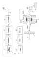
- FIG. 1 is a schematic configuration diagram showing an electron beam irradiation apparatus according to a first embodiment.
- FIG. 2(a) is a schematic diagram showing a phase rotator.
- FIG. 2(b) is a schematic diagram showing the course adjuster.
- FIG. 3 is a graph showing an example of the time structure of an electron beam.
- FIG. 4 is a diagram showing an example of the dose distribution of an electron beam.
- FIG. 5 is a graph showing the relationship between the relative dose of the electron beam and the depth of the irradiation target.
- FIG. 6A is a schematic diagram for explaining the relationship between the pulse width of an electron beam and the shielding effect.
- FIG. 6(b) is another schematic diagram for explaining the relationship between the pulse width of the electron beam and the shielding effect.
- FIG. 6A is a schematic diagram for explaining the relationship between the pulse width of an electron beam and the shielding effect.
- FIG. 7 is a schematic configuration diagram showing an electron beam irradiation device according to the second embodiment.
- FIG. 8(a) is a schematic configuration diagram showing an irradiation section according to a modification.
- FIG. 8(b) is a schematic configuration diagram showing an irradiation section according to another modification.
- the electron beam irradiation apparatus 100 irradiates an electron beam E to a prodrug D in the body of a patient (irradiation target) P, and uses the electron beam E as a trigger. It is a device that acts to convert prodrug D into an active substance.
- the electron beam irradiation apparatus 100 includes a patient table 1, an irradiation unit 10, a spin controller 2, a first magnetic field application section 3, a second magnetic field application section 4, an electric field application section 5, a beam monitor 41, a beam dump 6, and an operation input section. 20 and a control section 21.
- the prodrug D is a drug that, after reaching the target site in the body of the patient P, changes into an active substance (expresses activity) in response to a trigger.
- Prodrug D can exhibit activity and function at targeted locations.
- Prodrug D is not particularly limited and may be any prodrug.
- the prodrug D used is a drug that is inactive until it reaches the target site, and that can be converted into a drug such as an anticancer drug by a trigger at the target site.
- the prodrug D may be present deep within the body of the patient P (in the trunk).
- the patient table 1 is an arrangement section on which the patient P containing the prodrug D is placed.
- the irradiation unit 10 is a unit that irradiates the prodrug D inside the patient P on the patient table 1 with an electron beam E to convert the prodrug D into an active substance.
- the irradiation unit 10 includes a laser plasma driven electron accelerator 11, a phase rotator 12, and a path adjuster 13.
- the laser plasma-driven electron accelerator 11 is an electron accelerator that accelerates an electron beam by laser plasma acceleration.
- the acceleration energy of the laser plasma driven electron accelerator 11 is, for example, 1 to 300 MeV.
- the laser plasma-driven electron accelerator 11 constitutes an electron beam source that emits an electron beam E in the form of an ultrashort electron pulse with a spread in energy.
- the laser plasma-driven electron accelerator 11 includes an optical waveguide forming device that forms an optical waveguide for propagating a high-intensity laser pulse over a long distance, for example, by gas discharge in a discharge tube.
- the electron beam E generated by the laser plasma driven electron accelerator 11 has an energy chirp due to the energy spectrum being expanded by the fragmentation of the plasma wave.
- the energy chirp is a state in which the energy component of the electron beam E has a strong correlation with the traveling direction, and means that the energy component gradually changes from the front to the rear in the traveling direction of the electron beam E.
- the electron beam E generated by the laser plasma-driven electron accelerator 11 has, for example, a ⁇ E/E of 100 to 0.1%.
- E here is acceleration energy
- ⁇ E energy width (spectral width).
- the phase rotator 12 is a chirp adjustment unit that spatially rotates the electron beam E by 180° and inverts the energy chirp of the electron beam E.
- the phase rotator 12 adjusts the energy chirp of the electron beam E so that higher energy components are arranged at the rear in the beam traveling direction (in other words, lower energy components are arranged at the front in the beam traveling direction). adjust.
- an electronic bunch stretcher or the like can be used as the phase rotator 12.
- the phase rotator 12 includes magnetic field forming sections 12a, 12b, 12c, and 12d configured by dipole magnets.
- the phase rotator 12 electrons move to form semicircular orbits due to the magnetic fields of the magnetic field forming sections 12a, 12b, 12c, and 12d.
- the emitted electron beam E has an energy chirp in which the higher the energy component, the more rearward the electron beam E is located in the beam traveling direction.
- the path adjuster 13 compresses the pulse width of the electron beam E adjusted by the phase rotator 12.
- the path adjuster 13 adjusts the optical path of each energy component of the electron beam E to compress the pulse width of the electron beam E.
- the path adjuster 13 compresses the electron beam E in the longitudinal direction (direction along the traveling direction of the electron beam E).
- the path adjuster 13 adjusts the optical path of each energy component of the electron beam E so that the pulse width of the electron beam E is most compressed at the position of the prodrug D.
- an electronic bunch compressor or the like can be used as the phase rotator 12.
- the path adjuster 13 includes electromagnets 13a, 13b, 13c, and 13d.
- the electrons move to form an arcuate trajectory due to the magnetic fields of the electromagnets 13a, 13b, 13c, and 13d.
- the optical path of each energy component of the electron beam E is adjusted, and the optical path distance from the path adjuster 13 to the prodrug D is set to the distance at which the pulse width of the electron beam E is most compressed at the position of the prodrug D. .
- the electron beam E emitted from the irradiation unit 10 configured in this manner has, for example, the following characteristics. That is, the electron beam E has a pulse width of sub-picoseconds or less. Here, the electron beam E has a pulse width of 300 femtoseconds or less. Specifically, the electron beam E has a pulse width of 100 femtoseconds or less, more specifically, a pulse width of several femtoseconds or less.
- the electron beam E has energy that allows it to pass through the patient P and reach the prodrug D.
- the electron beam E has an energy of more than 1 MeV, here more than 10 MeV, in particular more than 200 MeV. Each condition of the electron beam E may be settable via the operation input section 20, for example. When the irradiation target is the patient P as in this embodiment, the electron beam E may have an energy greater than 10 MeV.
- the spin controller 2 controls the spins of the electron beam E emitted from the irradiation unit 10 so that they are aligned in a specific direction.
- the spin controller 2 spin-polarizes the electron beam E input from the irradiation unit 10 and emits the electron beam E with the spin directions aligned.
- the spin controller 2 here aligns the spins in a direction corresponding to the polarity of the prodrug D aligned by the electric field applying section 5.
- the spin controller 2 is not particularly limited, and various controllers may be used.
- the direction of the spins aligned by the spin controller 2 may be fixed or variable. When the direction of the spins aligned by the spin controller 2 is variable, the angle may be changeable via the operation input unit 20, for example.
- the first magnetic field applying unit 3 applies an external magnetic field to the electron beam E input from the spin controller 2 along the traveling direction (propagation direction) of the electron beam E.
- the first magnetic field application unit 3 focuses the electron beam E.
- the first magnetic field applying section 3 compresses the electron beam E in the lateral direction (direction perpendicular to the traveling direction).
- a pulse current driven electromagnet time-synchronized with the electron beam E is used as the first magnetic field applying section 3.
- the first magnetic field application section 3 constitutes a first application section.
- the first magnetic field applying section 3 is not limited to a material, and a superconducting magnet or the like may be used.
- the second magnetic field applying unit 4 applies an external magnetic field along the traveling direction of the electron beam E, which is irradiated to the prodrug D in the body of the patient P on the patient table 1.
- the second magnetic field applying section 4 includes an upstream applying section 4A disposed upstream of the patient table 1 in the traveling direction of the electron beam E, and a downstream side applying section 4A disposed downstream of the patient table 1 in the traveling direction of the electron beam.
- An application section 4B is included.
- As the upstream application section 4A and the downstream application section 4B for example, pulsed current-driven electromagnets time-synchronized with the electron beam E are used.
- the second magnetic field application section 4 focuses the electron beam E between the upstream application section 4A and the downstream application section 4B.
- the second magnetic field application section 4 compresses the electron beam E in the lateral direction between the upstream application section 4A and the downstream application section 4B.
- the second magnetic field application section 4 constitutes a first application section.
- the second magnetic field applying unit 4 is not limited to this, and a superconducting magnet or the like may be used.
- the electric field applying unit 5 applies an external electric field to the prodrug D inside the patient P placed on the patient table 1 so that the polarity directions of the prodrug D are aligned.
- the electric field applying section 5 is provided with electrodes 5A and 5B so as to sandwich the patient P therebetween.
- the direction in which the electrodes 5A and 5B of the electric field application section 5 face each other is perpendicular to the direction in which the electron beam E travels.
- the direction of polarity aligned by the electric field applying section 5 may be fixed or variable. If the direction of the polarities aligned by the electric field applying section 5 is variable, the angle may be changeable via the operation input section 20, for example.
- the direction of the polarity aligned by the electric field applying unit 5 may be a direction corresponding to the direction of the spins aligned by the spin controller 2.
- the electric field application section 5 constitutes a second application section.
- the beam monitor 41 is a device that measures the electron beam E that has passed through the prodrug D.
- the beam monitor 41 monitors at least one of the position, intensity, shape, and dose of the electron beam E that has passed through the prodrug D.
- the beam monitor 41 is not particularly limited, and any known monitor can be used.
- the beam dump 6 is a device that absorbs and stops the electron beam E that has passed through the prodrug D and has been measured by the beam monitor 41.
- the beam dump 6 is provided on the downstream side of the patient table 1 in the optical path of the electron beam E.
- the beam dump 6 is not particularly limited, and a known device can be used.
- the operation input unit 20 is an input unit that can accept various inputs from the user.
- the operation input unit 20 for example, a touch panel, a microphone, a camera, etc. are used. Inputs from the operation input unit 20 include touch input, voice input, camera input, and the like.
- the operation input unit 20 inputs, for example, each condition of the electron beam E emitted from the irradiation unit 10, the direction of spins aligned by the spin controller 2, the direction of polarity aligned by the electric field application unit 5, and prodrug information regarding the prodrug D. is configured so that it can be entered.
- the prodrug information includes at least information regarding the type of prodrug D.
- the control unit 21 is configured by, for example, one or more computer devices.
- the control unit 21 includes a CPU (Central Processing Unit) which is a processor, a RAM (Random Access Memory) or a ROM (Read Only Memory) which is a recording medium, and the like.
- the control unit 21 executes various controls by loading programs and the like onto hardware such as the CPU and RAM.
- the control section 21 controls each condition of the electron beam E irradiated by the irradiation unit 10 based on input from the operation input section 20 .
- the control unit 21 controls the time structure of a plurality of electron pulses included in the electron beam E irradiated by the irradiation unit 10 based on the prodrug information input through the operation input unit 20. Specifically, the control unit 21 refers to the data table stored in the storage unit 22 based on the type of prodrug D in the input prodrug information, and controls the time structure of the electron pulses included in the electron beam E. do.
- the time structure of the electronic pulse includes at least one of the intensity, intensity ratio, time interval, and pulse width of the plurality of electronic pulses 30.
- the type of prodrug D and the time structure of the electronic pulse are associated with each other.
- the data table can be obtained in advance by actual measurement or simulation.
- the patient P When using the electron beam irradiation device 100 described above, first, the patient P, to whom the prodrug D has been delivered to the target site in the body, is placed on the patient table 1. At the same time, each condition of the electron beam E to be irradiated, prodrug information, the spin direction of the electron beam E, and the polarity direction of the prodrug D are inputted using the operation input unit 20. Thereby, the irradiation unit 10 is controlled by the control unit 21, and has, for example, an energy larger than 200 MeV, a pulse width of 100 femtoseconds or less, and a time structure of an electron pulse according to the type of prodrug D. An electron beam E is emitted from the irradiation unit 10.
- the electron beam E emitted from the irradiation unit 10 has its spin direction aligned by the spin controller 2, and is focused by the first magnetic field application unit 3, and then reaches the target inside the body of the patient P placed on the patient table 1.
- Drug D is selectively irradiated.
- the electron beam E is focused by the second magnetic field applying section 4.
- the polarity directions of the prodrugs D are aligned by the electric field applying section 5.
- the high-energy electron beam E has low energy attenuation in the substance, so the electron beam E can sufficiently reach the prodrug D present deep within the patient P. Therefore, even when the prodrug D exists deep inside the patient P, the electron beam E can be selectively applied to the prodrug D at a sufficient dose and the electron beam E can act as a trigger. Thereby, it becomes possible to activate prodrug D, convert it into an active substance, and express its activity.
- the electron beam irradiation device 100 and the electron beam irradiation method it is possible to express the activity of the prodrug D deep in the patient P.
- the irradiation of the electron beam E which can three-dimensionally control the application of energy into the body of the patient P, it becomes possible to express the activity and function of the prodrug D deep in the trunk.
- the electron beam irradiation device 100 includes a first magnetic field applying section 3 and a second magnetic field applying section 4.
- the directivity of the electron beam E can be increased, and the pencil beam-shaped electron beam E can be selectively applied at a sufficient dose to the prodrug D present deep inside the patient P. It becomes possible to bring out the effects significantly. It is possible to suppress the problem of scattering of even a high-energy electron beam E in a substance and maintain the directivity of the electron beam E.
- the prodrug D can be efficiently activated while reducing the effect on the human body.
- FIG. 4 is a diagram showing an example of the dose distribution of the electron beam E.
- FIG. 4 shows numerical simulation results showing how an electron beam E having an energy of 200 MeV propagates through water.
- the horizontal axis is the position of the electron beam E in the traveling direction
- the vertical axis is the position in the direction perpendicular to the traveling direction.
- a 3T magnetic field is applied in the traveling direction of the electron beam E. The darker the shading in the figure, the greater the dose (flux) of the electron beam E.
- FIG. 4 it can be seen that in this embodiment, the diffusion of the electron beam E is suppressed, the electron beam E is focused into a pencil beam shape, and the directivity is enhanced.
- the irradiation unit 10 includes a laser plasma-driven electron accelerator 11, a phase rotator 12, and a path adjuster 13.
- the pulse width is automatically gradually compressed and the charge density increases, and It becomes possible to increase the energy imparted to the prodrug D while suppressing the energy imparted to the prodrug D. That is, it becomes possible to realize beam irradiation that selectively imparts large energy to the prodrug D in the body of the patient P using the electron beam E.
- the prodrug D can be efficiently activated while reducing the effect on the human body.
- FIG. 5 is a graph showing the dose distribution of the electron beam E.
- the vertical axis in the figure is the relative dose of the electron beam E
- the horizontal axis in the figure is the depth of the patient P from the electron beam incident surface.
- the relative dose of the electron beam E is maintained at a low level in the depth region up to the prodrug D
- the relative dose of the electron beam E at the depth of the prodrug D is The relative dose is increasing rapidly.
- the electron beam E is used, it can be expected that irradiation similar to the Bragg peak characteristics of a hadron beam can be performed with the electron beam.
- the electron beam E has a pulse width of sub-picoseconds or less.
- the effect of the electric field of the electron beam E on the prodrug D is enhanced, and the activity of the prodrug D is expressed more efficiently than, for example, when the electron beam E has a pulse width in the nanosecond to picosecond range.
- the prodrug D can be changed into an active substance with a small total dose), and the radiation exposure dose of the patient P can be reduced.
- FIG. 6 is a schematic diagram for explaining the relationship between the pulse width of the electron beam E and the shielding effect.
- the electron beam E propagates in a condensed dipole medium (water)
- the electrons 7 in the electron beam E are blocked by water molecules 8. Therefore, the electric field 9 created by the electrons 7 is small and does not affect the movement and dynamics of the electron beam E.
- a finite amount of time is required for the polarization reaction. For example, assuming that the rotational speed v of the dipole is 10 5 cm/s and the length l of the dipole is 3 ⁇ 10 -8 cm, the relaxation time TR obtains 300 fs (3 ⁇ 10 ⁇ 13 s: femtoseconds).
- the pulse width of the electron beam E is shorter than the relaxation time, the water molecules 8 will block the electric field 9 only on the surface of the electron beam E, as shown in FIG. 6(b). Therefore, a region of strong electric field 9 is formed. From this point of view, it is significant that the electron beam E has a pulse width of sub-picoseconds or less.
- the electron beam irradiation device 100 includes an operation input section 20 and a control section 21.
- the time structure for example, intensity, intensity ratio, time interval, each pulse width, etc.
- the control unit 21 based on prodrug information input via the operation input unit 20. This makes it possible to control the chemical reaction caused by the interaction between the electron pulse 30 and the prodrug D, and to control, for example, the structure, type, yield, yield ratio, etc. of the active substance changed from the prodrug D.
- the spin controller 2 aligns the spin directions of the electron beam E from the irradiation unit 10. In this case, it becomes possible to control, for example, the structure, type, yield, yield ratio, etc. of the active substance changed from the prodrug D to be in accordance with the direction of the aligned spins of the electron beam E. Note that the spin controller 2 may align the spin directions according to the polarity directions of the prodrug D aligned by the electric field application unit 5, or may align the spins independently.
- the electron beam irradiation device 100 includes an electric field applying section 5.
- an electric field applying section 5 it becomes possible to control, for example, the structure, type, yield, yield ratio, etc. of the active substance changed from prodrug D to be in accordance with the aligned polarity direction of prodrug D.
- the electric field applying section 5 may align the polarity direction according to the spin direction of the electron beam E aligned by the spin controller 2, or may align the polarity independently.
- the irradiation unit 10 and the spin controller 2 constitute an irradiation section.
- the first magnetic field applying section 3 and the second magnetic field applying section 4 constitute a magnetic field applying section.
- At least one of the phase rotator 12, the path adjuster 13, the spin controller 2, the first magnetic field application section 3, the second magnetic field application section 4, and the electric field application section 5 may be omitted depending on the case.
- the positional relationship between the patient table 1 and the irradiation unit 10 is controlled so that the electron beam E from the irradiation unit 10 is appropriately incident on the prodrug D in the body of the patient P on the patient table 1.
- the control unit 21 may be configured to be controllable.
- the operation input unit 20 may be configured to be able to input position information of the prodrug D in the body of the patient P.
- the positional relationship between the patient table 1 and the irradiation unit 10 may be configured to be controllable by the control unit 21 so that the electron beam E is incident on the prodrug D based on the positional information.
- the electric field applying section 5 may be provided so that its relative positional relationship with respect to the patient table 1 can be changed. Thereby, an external electric field can be easily applied toward the prodrug D inside the patient P on the patient table 1.
- This embodiment includes the following electron beam irradiation method.
- the electron beam irradiation method includes the steps of arranging an irradiation target containing a prodrug therein in a placement section (placement step), and irradiating the prodrug inside the irradiation target placed in the placement section with electrons having an energy greater than 1 MeV. irradiating the prodrug with a beam to convert the prodrug into an active substance (irradiation step).
- the electron beam irradiation method corresponds to the method of using the electron beam irradiation apparatus 100.
- the electron beam irradiation method includes a magnetic field application step of applying an external magnetic field along the traveling direction of the electron beam to the electron beam.
- the irradiation step includes a step of generating an electron beam having an energy chirp, and a step of adjusting the energy chirp of the generated electron beam so that higher energy components are arranged at the rear in the beam traveling direction. and has.
- the electron beam has a pulse width of sub-picoseconds or less.
- the electron beam irradiation method includes an input step of inputting prodrug information regarding the prodrug, and a control step of controlling the temporal structure of a plurality of electron pulses 30 included in the irradiated electron beam based on the prodrug information. , is provided.
- the irradiation step emits an electron beam with aligned spin directions.
- the electron beam irradiation method includes an electric field application step of applying an external electric field to the prodrug inside the irradiation target placed in the placement section so that the polar directions of the prodrug are aligned.
- the prodrug inside the placed irradiation target is irradiated with an electron beam from a plurality of directions.
- This embodiment may be used for simultaneous activation of multiple prodrugs.
- multidrug therapy in which multiple anticancer drugs are used in combination is often performed, but in this case, the toxicity of each anticancer drug becomes an issue.
- this embodiment by converting each of the anticancer drugs used in combination into prodrugs (inactivating them) and simultaneously activating them by electron beam irradiation, it is expected that the treatment satisfaction level of multidrug combination therapy will be increased ( multi-prodrug therapy).
- this embodiment may be used for a molecule in which a plurality of anticancer drugs are linked into one molecule via a linker or the like and activated by a plurality of prodrugs D (dual prodrug therapy).
- the prodrug may include a drug carrier in a broad sense.
- a drug carrier is something that encapsulates a drug, such as polymer micelles, liposomes, nanomachines, and the like. That is, in one aspect of the present invention, it can also be used for site-specific disruption of drug carriers and drug release. By irradiating drug carriers accumulated in diseased areas such as cancer tissues with high-energy electron beams, selective collapse of drug carriers in the affected areas and subsequent drug release is expected.
- hydrated electrons are generated from water molecules as a first step by high-energy electron beam irradiation (see the formula below). H 2 0 ⁇ H 2 O + +e aq - (initial step)
- hydrated electrons act on the amphiphilic molecules constituting the drug carrier, causing the chemical structure to change, and after the drug carrier collapses, the drug (drug-encapsulating core) is released.
- An example in which hydrated electrons react with such amphiphilic molecules is considered to require a higher dose than the above-mentioned example in which hydrated electrons react with a mask.
- This embodiment may be used to treat neurodegenerative diseases such as Alzheimer's disease and brain diseases such as brain tumors.
- the administered drug When targeting brain diseases, the administered drug must move from the bloodstream into the brain, but in this case it must pass through the blood-brain barrier that separates the blood and brain tissue.
- drugs with high fat solubility have a high ability to penetrate the brain.
- a prodrug D with improved fat solubility is created by masking substituents with low fat solubility in the drug, and after it reaches the brain, it is activated by irradiation with an electron beam E. , it is expected that it will be possible to improve the penetration into the brain and to have a brain-specific effect.
- Drug delivery systems can deliver drugs to desired locations by utilizing the EPR (enhanced permeability) effect. That is, blood vessels have gaps that allow oxygen or nutrients to be taken into cells outside the blood vessels. In normal blood vessels, this gap is very small, and while low-molecular substances can pass through the blood vessel wall, high-molecular substances cannot. Blood vessels in tumor tissues have many branches because they are formed by angiogenesis accompanying tumor growth, and the vessel walls are rougher than normal blood vessels, with gaps of, for example, about 100 to 200 nm. Taking advantage of this difference, drug carriers can accumulate drugs in tumor tissues.
- EPR enhanced permeability
- ADC Antibody-Drug Conjugate
- ADC antibody-drug complex
- Antibodies are used as the functional site for precise target recognition and delivery, and the drug is responsible for the actual drug efficacy. Therefore, by using an ADC, a drug can be specifically delivered to cells recognized by the antibody used.
- the electron beam irradiation device 200 is a drug discovery platform used for the development of prodrug D.
- the electron beam irradiation device 200 is a device that irradiates the prodrug D inside the test tube (irradiation target) S with an electron beam E, and uses the electron beam E as a trigger to convert the prodrug D into an active substance. It is.
- the electron beam irradiation apparatus 200 differs from the first embodiment in that it includes a test tube holder 201 instead of the patient table 1 (see FIG. 1) and further includes a beam deflection magnet 205.
- the test tube holder 201 holds and arranges the test tube S containing the prodrug D therein.
- Beam deflection magnet 205 is arranged between beam monitor 41 and beam dump 6.
- the beam deflection magnet 205 deflects the electron beam E, which has passed through the prodrug D and has been measured by the beam monitor 41, toward the beam dump 6.
- the electron beam E of this embodiment has energy that allows it to pass through the test tube S and reach the prodrug D.
- the electron beam E may have an energy greater than 1 MeV.
- the electron beam irradiation device 200 also produces effects similar to those of the first embodiment, that is, effects such as being able to express the activity of prodrug D deep in the patient P.
- the beam deflection magnet 205 may be omitted depending on the case.
- the above embodiment may further include a phantom (water cell) placed between the irradiation unit 10 and the patient P (preferably in front of the patient P's body) on the optical path of the electron beam E.
- This phantom functions similarly to the path adjuster 13 and can adjust the compression point of the electron beam E to become the prodrug D in the patient P's body.
- the irradiation target is not particularly limited, and may be various targets.
- the above embodiment may include an irradiation unit 110 shown in FIG. 8(a) instead of the irradiation unit 10 (see FIG. 1).
- the irradiation unit 110 includes a high frequency electron accelerator 111 and a pulse compressor 112.
- the high frequency electron accelerator 111 emits a monochromatic (single energy) electron pulsed electron beam E1.
- the pulse compressor 112 compresses the pulse of the electron beam E1 emitted by the high-frequency electron accelerator 111, and outputs the compressed pulse to the subsequent spin controller 2 (see FIG. 1).
- the pulse compressor 112 compresses the pulse width of the electron beam E1 to several nanoseconds to several femtoseconds. Note that the pulse compressor 112 may not be provided depending on the case (see the irradiation unit 210 in FIG. 8(b)).
- the irradiation units 110 and 210 constitute an irradiation section.
- the irradiation unit may be capable of irradiating the prodrug inside the irradiation target placed in the placement unit with an electron beam from a plurality of directions.
- the emission side of the irradiation unit 10 is configured to be movable around the irradiation target, and the prodrug D can be irradiated with the electron beam E multiple times by changing the position of the emission side of the irradiation unit 10. good.
- the spin controller 2 may not be provided.
- the spin controller 2 it becomes possible to easily and reliably control and align the spins of the electron beams E by the spin controller 2.
- the above embodiment includes the electric field application unit 5 as the second application unit, but instead of or in addition to this, an external magnetic field is applied to the prodrug D so that the polarity direction of the prodrug D is aligned.
- An application unit for example, an MRI (Magnetic Resonance Imaging) device
- MRI Magnetic Resonance Imaging
- the above embodiment may further include a phantom (water cell) placed on the optical path of the electron beam E between the phase rotator 12 and the irradiation target (preferably in front of the irradiation target).
- This phantom functions as an electron beam compressor like the path adjuster 13, and can adjust the compression point of the electron beam E to become the prodrug D inside the irradiation target.
- the patient P and the test tube S were irradiated with the electron beam E, but the irradiation targets are not particularly limited.
- the external electric field and external magnetic field for aligning the polar directions of the prodrug D can be generated and applied using various known methods.
Landscapes
- Health & Medical Sciences (AREA)
- Engineering & Computer Science (AREA)
- Biomedical Technology (AREA)
- Pathology (AREA)
- Nuclear Medicine, Radiotherapy & Molecular Imaging (AREA)
- Radiology & Medical Imaging (AREA)
- Life Sciences & Earth Sciences (AREA)
- Animal Behavior & Ethology (AREA)
- General Health & Medical Sciences (AREA)
- Public Health (AREA)
- Veterinary Medicine (AREA)
- Radiation-Therapy Devices (AREA)
Abstract
内部にプロドラッグを含む照射対象を配置する配置部と、配置部に配置された照射対象の内部のプロドラッグに1MeVよりも大きいエネルギーの電子ビームを照射し、当該プロドラッグを活性物質へ変化させる照射部と、を備える、電子ビーム照射装置。
Description
本発明の一側面は、電子ビーム照射装置及び電子ビーム照射方法に関する。
プロドラッグは、例えば体内の目標部位に到達してから、内在性及び外来のトリガーによって活性物質へ変化する薬物であり、狙った箇所にて活性を発現させ得る。内在性のトリガーとしては、酸化的環境又は酸性環境を利用した手法、及び、腸内細菌由来のアゾレダクターゼを用いる手法等が知られている。外来のトリガーとしては、光照射を用いる手法、及び、金属触媒や生体触媒を活用する手法等が知られている。
しかし、これらの手法では、狙った箇所以外においても、プロドラッグの活性の発現が起こることが多い。そこで、例えば非特許文献1に記載されているように、X線をプロドラッグに照射し、その照射部位を活性物質へ変化させ、活性を発現する手法が開発されている。
Jin Geng、他9名、"Switching on prodrugs using radiotherapy"、Nature Chemistry,VOL 13,AUGUST 2021,805-810
照射対象の深部にプロドラッグが存在する場合、X線は物質中のエネルギー減衰が大きいことから、当該プロドラッグにはX線が届きにくい。そのため、上述した手法は、照射対象の表面付近でプロドラッグの活性を発現させる場合には適用され得るが、照射対象の深部でプロドラッグの活性を発現させる場合には適用され難い。
本発明の一側面は、照射対象の深部においてもプロドラッグの活性を発現させることが可能な電子ビーム照射装置及び電子ビーム照射方法を提供することを課題とする。
本発明者らは鋭意検討を重ねた結果、プロドラッグに高エネルギーの電子ビームを照射することで、この高エネルギーの電子ビームをトリガーとして作用させ、プロドラッグを活性物質へ変化できるという知見を得た。そして、高エネルギーの電子ビームは、物質中のエネルギー減衰が低いことから、照射対象の深部に存在するプロドラッグに対しても十分に届き得ることを見出し、本発明の一側面を完成するに至った。
すなわち、本発明の一側面に係る電子ビーム照射装置は、内部にプロドラッグを含む照射対象を配置する配置部と、配置部に配置された照射対象の内部のプロドラッグに1MeVよりも大きいエネルギーの電子ビームを照射し、当該プロドラッグを活性物質へ変化させる照射部と、を備える。本発明の一側面に係る電子ビーム照射方法は、内部にプロドラッグを含む照射対象を配置部に配置するステップと、配置部に配置した照射対象の内部のプロドラッグに1MeVよりも大きいエネルギーの電子ビームを照射し、当該プロドラッグを活性物質へ変化させるステップと、を備える。
電子ビーム照射装置及び電子ビーム照射方法では、照射対象の内部の深い箇所にプロドラッグが存在する場合でも、当該プロドラッグに電子ビームを十分な線量で選択的に当て、その活性を発現させることが可能となる。したがって、照射対象の深部においてプロドラッグの活性を発現させることが可能となる。
本発明の一側面に係る電子ビーム照射装置は、電子ビームに対して当該電子ビームの進行方向に沿った外部磁場を印加する第1印加部を備えていてもよい。この場合、電子ビームの指向性を高めることができ、照射対象の内部の深い箇所に存在するプロドラッグに電子ビームを十分な線量で選択的に当てることができる上記作用効果を、顕著に発揮させることが可能となる。
本発明の一側面に係る電子ビーム照射装置では、照射部は、エネルギーチャープを有する電子ビームを生成する電子ビーム源と、電子ビーム源で生成した電子ビームのエネルギーチャープを、高いエネルギー成分ほどビーム進行方向の後方に配置されるように調整するチャープ調整部と、を有していてもよい。この場合、電子ビームは、照射対象内のプロドラッグに至るまでの伝搬に伴って、自動的に徐々にパルス幅が圧縮されて電荷密度が高まっていき、照射対象においてプロドラッグ以外へのエネルギー付与を抑える一方でプロドラッグへのエネルギー付与を高めることが可能となる。すなわち、照射対象内のプロドラッグに選択的に大きなエネルギー付与を与えるビーム照射を、電子ビームを用いて実現することが可能となる。
本発明の一側面に係る電子ビーム照射装置では、電子ビームは、サブピコ秒以下のパルス幅を有していてもよい。この場合、電子ビームの電場がプロドラッグへ与える効果を高め、例えば電子ビームがナノ秒~ピコ秒の範囲のパルス幅を有する場合と比べて、プロドラッグの活性を効率的に発現させることが可能となる。
本発明の一側面に係る電子ビーム照射装置は、プロドラッグに関するプロドラッグ情報を入力可能な入力部と、照射部により照射される電子ビームに含まれる複数の電子パルスの時間構造を、プロドラッグ情報に基づいて制御する制御部と、を備えていてもよい。この場合、複数の電子パルスの時間構造をプロドラッグ情報に基づき制御することで、電子パルスとプロドラッグとの相互作用による化学反応を制御し、プロドラッグから変化させた活性物質の例えば構造、種類、収量及び収量比等をコントロールすることが可能となる。複数の電子パルスの時間構造は、例えば、複数の電子パルスについての強度、強度比、各時間間隔、及び、各パルス幅の少なくとも何れかを含んでいてもよい。
本発明の一側面に係る電子ビーム照射装置では、照射部は、スピンの向きを揃えた電子ビームを出射してもよい。この場合、プロドラッグから変化させた活性物質の例えば構造、種類、収量及び収量比等を、電子ビームのスピンの向きに応じたものへコントロールすることが可能となる。
本発明の一側面に係る電子ビーム照射装置は、配置部に配置された照射対象の内部のプロドラッグに対して、当該プロドラッグの極性の向きが揃うように外部電場又は外部磁場を印加する第2印加部を備えていてもよい。この場合、プロドラッグから変化させた活性物質の例えば構造、種類、収量及び収量比等を、プロドラッグの極性の向きに応じたものへコントロールすることが可能となる。
本発明の一側面に係る電子ビーム照射装置では、照射部は、配置部に配置された照射対象の内部のプロドラッグに対して、複数の方向から電子ビームを照射可能であってもよい。この場合、プロドラッグへの複数の方向からの電子ビームの照射により、照射対象においてプロドラッグ以外へのエネルギー付与を抑える一方で、プロドラッグへのエネルギー付与を高めることが可能となる。
本発明の一側面によれば、照射対象の深部においてもプロドラッグの活性を発現させることが可能な電子ビーム照射装置及び電子ビーム照射方法を提供することが可能となる。
以下、図面を参照しつつ実施形態について詳細に説明する。以下の説明において同一又は相当要素には同一符号を付し、重複する説明を省略する。
[第1実施形態]
図1に示されるように、第1実施形態に係る電子ビーム照射装置100は、患者(照射対象)Pの体内のプロドラッグDに対して電子ビームEを照射し、その電子ビームEをトリガーとして作用させてプロドラッグDを活性物質へ変化させる装置である。電子ビーム照射装置100は、患者台1、照射ユニット10、スピン制御器2、第1磁場印加部3、第2磁場印加部4、電場印加部5、ビームモニター41、ビームダンプ6、操作入力部20及び制御部21を備える。
図1に示されるように、第1実施形態に係る電子ビーム照射装置100は、患者(照射対象)Pの体内のプロドラッグDに対して電子ビームEを照射し、その電子ビームEをトリガーとして作用させてプロドラッグDを活性物質へ変化させる装置である。電子ビーム照射装置100は、患者台1、照射ユニット10、スピン制御器2、第1磁場印加部3、第2磁場印加部4、電場印加部5、ビームモニター41、ビームダンプ6、操作入力部20及び制御部21を備える。
プロドラッグDは、患者Pの体内の目標部位に到達してから、トリガーによって活性物質へ変化(活性を発現)する薬物である。プロドラッグDは、狙った箇所にて活性及び機能を発現させ得る。プロドラッグDは、特に限定されず、あらゆるプロドラッグであってもよい。例えばプロドラッグDとしては、目標部位に到達するまでは不活性な薬剤であって、目標部位においてはトリガーによって抗がん剤等の薬へ変化可能なものが用いられる。プロドラッグDは、患者Pの体内において深い位置(体幹部)に存在していてもよい。
患者台1は、内部にプロドラッグDを含む患者Pを載せて配置する配置部である。照射ユニット10は、患者台1上の患者Pの内部のプロドラッグDに電子ビームEを照射し、当該プロドラッグDを活性物質へ変化させるユニットである。照射ユニット10は、レーザプラズマ駆動電子加速器11と、位相回転器12と、行路調整器13と、を有する。
レーザプラズマ駆動電子加速器11は、レーザプラズマ加速により電子ビームを加速する電子加速器である。レーザプラズマ駆動電子加速器11の加速エネルギは、例えば1~300MeVである。レーザプラズマ駆動電子加速器11は、エネルギーに拡がりを持った超短電子パルスの電子ビームEを出射する電子ビーム源を構成する。レーザプラズマ駆動電子加速器11は、例えば高強度レーザパルスを長距離伝播させる光導波路を、放電管中のガス放電によって形成する光導波路形成装置を備える。
レーザプラズマ駆動電子加速器11により生成した電子ビームEは、プラズマ波の破砕によってエネルギースペクトルが拡がることで、エネルギーチャープを有する。エネルギーチャープとは、電子ビームEのエネルギー成分が進行方向と強い相関のある状態であって、電子ビームEの進行方向の前方から後方にかけてエネルギー成分が徐々に変わっている状態を意味する。レーザプラズマ駆動電子加速器11により生成した電子ビームEは、例えばΔE/Eが100~0.1%である。ここでのEは、加速エネルギーであり、ΔEは、エネルギー巾(スペクトル巾)である。ΔEは、例えば、加速エネルギーの分布の半値幅に対応する。例えばΔE/E=10MeV/100MeV=10%である。
位相回転器12は、電子ビームEを空間的に180°回転させ、電子ビームEのエネルギーチャープを反転させるチャープ調整部である。位相回転器12は、高いエネルギー成分ほどビーム進行方向の後方に配置されるように(換言すると、低いエネルギー成分ほどビーム進行方向の前方に配置されるように)、当該電子ビームEのエネルギーチャープを調整する。位相回転器12としては、電子バンチストレッチャー等を用いることができる。
例えば図2(a)に示されるように、位相回転器12は、ダイポール磁石によって構成される磁場形成部12a,12b,12c,12dを含む。位相回転器12では、磁場形成部12a,12b,12c,12dの磁場により電子が半円軌道を形成するように動く。これにより、出射される電子ビームEは、高いエネルギー成分ほどビーム進行方向の後方に配置されるエネルギーチャープを有する。
行路調整器13は、位相回転器12で調整した電子ビームEのパルス幅を圧縮する。行路調整器13は、電子ビームEの各エネルギー成分の光路を調整して、当該電子ビームEのパルス幅を圧縮する。行路調整器13は、電子ビームEを縦方向(電子ビームEの進行方向に沿う方向)に圧縮する。行路調整器13は、電子ビームEのパルス幅がプロドラッグDの位置で最も圧縮されるように、当該電子ビームEの各エネルギー成分の光路を調整する。位相回転器12としては、電子バンチコンプレッサ等を用いることができる。
例えば図2(b)に示されるように、行路調整器13は、電磁石13a,13b,13c,13dを含む。行路調整器13では、電磁石13a,13b,13c,13dの磁場により電子が弧状の軌道を形成するように動く。これにより、電子ビームEの各エネルギー成分の光路を調整し、行路調整器13からプロドラッグDまでの光路距離を、電子ビームEのパルス幅がプロドラッグDの位置で最も圧縮される距離とする。
このように構成された照射ユニット10から出射された電子ビームEは、一例として、次の特性を有する。すなわち、電子ビームEは、サブピコ秒以下のパルス幅を有する。ここでは、電子ビームEは、300フェムト秒以下のパルス幅を有する。具体的には、電子ビームEは、100フェムト秒以下のパルス幅を有し、より具体的には、数フェムト秒以下のパルス幅を有する。電子ビームEは、患者Pを透過してプロドラッグDへ到達可能なエネルギーを有する。電子ビームEは、1MeVよりも大きいエネルギーを有し、ここでは、10MeVよりも大きいエネルギーを有し、具体的には、200MeVよりも大きいエネルギーを有する。電子ビームEの各条件は、例えば、操作入力部20を介して設定可能であってもよい。本実施形態のように照射対象が患者Pの場合、電子ビームEは、10MeVよりも大きいエネルギーを有していてもよい。
図1に戻り、スピン制御器2は、照射ユニット10から出射された電子ビームEのスピンを、特定の方向に揃うように制御する。スピン制御器2は、照射ユニット10から入力された電子ビームEをスピン偏極させ、スピンの向きを揃えた当該電子ビームEを出射する。ここでのスピン制御器2は、電場印加部5により揃えたプロドラッグDの極性に対応する方向へ、スピンを揃える。スピン制御器2としては特に限定されず、種々の制御器を用いてもよい。スピン制御器2により揃えるスピンの方向は、固定でもよいし、可変でもよい。スピン制御器2により揃えるスピンの方向が可変の場合、例えば、操作入力部20を介して、その角度が変更可能であってもよい。
第1磁場印加部3は、スピン制御器2から入力された電子ビームEに対して、当該電子ビームEの進行方向(伝播方向)に沿った外部磁場を印加する。第1磁場印加部3は、電子ビームEを集束させる。第1磁場印加部3は、電子ビームEを横方向(進行方向に垂直な方向)に圧縮する。第1磁場印加部3としては、例えば電子ビームEと時間同期したパルス電流駆動の電磁石が用いられる。第1磁場印加部3は、第1印加部を構成する。第1磁場印加部3としては限定されず、超伝導磁石等を用いてもよい。
第2磁場印加部4は、患者台1上の患者Pの体内のプロドラッグDに照射される電子ビームEに対して、当該電子ビームEの進行方向に沿った外部磁場を印加する。第2磁場印加部4は、電子ビームEの進行方向における患者台1の上流側に配置された上流側印加部4Aと、電子ビームの進行方向における患者台1の下流側に配置された下流側印加部4Bと、を含む。上流側印加部4A及び下流側印加部4Bとしては、例えば電子ビームEと時間同期したパルス電流駆動の電磁石が用いられる。第2磁場印加部4は、上流側印加部4Aと下流側印加部4Bとの間において電子ビームEを集束させる。第2磁場印加部4は、上流側印加部4Aと下流側印加部4Bとの間において電子ビームEを横方向に圧縮する。第2磁場印加部4は、第1印加部を構成する。第2磁場印加部4としては限定されず、超伝導磁石等を用いてもよい。
電場印加部5は、患者台1に配置された患者Pの内部のプロドラッグDに対して、当該プロドラッグDの極性の向きが揃うように外部電場を印加する。電場印加部5は、患者Pを挟むように各電極5A,5Bが設けられている。電場印加部5の電極5A,5Bが対向する方向は、電子ビームEの進行方向と直交する。電場印加部5により揃える極性の向きは、固定でもよいし、可変でもよい。電場印加部5により揃える極性の向きが可変の場合、例えば、操作入力部20を介して、その角度が変更可能であってもよい。電場印加部5により揃える極性の向きは、スピン制御器2により揃えるスピンの方向に応じた向きであってもよい。電場印加部5は、第2印加部を構成する。
ビームモニター41は、プロドラッグDを透過した電子ビームEを計測する装置である。ビームモニター41は、プロドラッグDを透過した電子ビームEの位置、強度、形状及び線量の少なくとも何れかをモニターする。ビームモニター41としては特に限定されず、公知のモニターを用いることができる。ビームダンプ6は、プロドラッグDを透過し且つビームモニター41で計測済みの電子ビームEを吸収して止める装置である。ビームダンプ6は、電子ビームEの光路において患者台1の下流側に設けられている。ビームダンプ6は特に限定されず、公知の装置を用いることができる。
操作入力部20は、ユーザにより各種の入力を受付け可能な入力部である。操作入力部20としては、例えばタッチパネル、マイク及びカメラ等が用いられる。操作入力部20の入力としては、タッチ入力、音声入力、カメラ入力等が挙げられる。操作入力部20は、例えば、照射ユニット10から出射する電子ビームEの各条件、スピン制御器2により揃えるスピンの方向、電場印加部5により揃える極性の向き、及び、プロドラッグDに関するプロドラッグ情報が入力可能に構成されている。プロドラッグ情報は、プロドラッグDの種類に関する情報を少なくとも含む。
制御部21は、例えば一以上のコンピュータ装置により構成される。制御部21は、プロセッサであるCPU(Central Processing Unit)、記録媒体であるRAM(Random Access Memory)又はROM(Read Only Memory)等を含んで構成される。制御部21は、CPU及びRAM等のハードウェア上にプログラム等を読み込ませることにより、各種の制御を実行する。制御部21は、照射ユニット10により照射される電子ビームEの各条件を、操作入力部20の入力に基づいて制御する。
制御部21は、照射ユニット10により照射される電子ビームEに含まれる複数の電子パルスの時間構造を、操作入力部20で入力されたプロドラッグ情報に基づいて制御する。具体的には、制御部21は、入力されたプロドラッグ情報のプロドラッグDの種類から、記憶部22に記憶されたデータテーブルを参照し、電子ビームEに含まれる電子パルスの時間構造を制御する。例えば電子パルスの時間構造としては、図3に示されるように、複数の電子パルス30についての強度、強度比、各時間間隔、及び、各パルス幅の少なくとも何れかを含む。例えばデータテーブルでは、プロドラッグDの種類と電子パルスの時間構造とが互いに関連付けられてなる。データテーブルは、予め実測又はシミュレーション等により取得することができる。
以上に説明した電子ビーム照射装置100を用いる場合、まず、体内の目標部位にプロドラッグDを到達させた患者Pを、患者台1に配置する。これと共に、操作入力部20により、照射する電子ビームEの各条件、プロドラッグ情報、電子ビームEのスピン向き、及び、プロドラッグDの極性の向きを入力する。これにより、制御部21により照射ユニット10が制御され、例えば、200MeVよりも大きいエネルギーで100フェムト秒以下のパルス幅を有し、且つ、プロドラッグDの種類に応じた電子パルスの時間構造を有する電子ビームEが、照射ユニット10から出射される。
照射ユニット10から出射された電子ビームEは、スピン制御器2によりそのスピンの方向が揃えられ、第1磁場印加部3により集束された後、患者台1に載せられた患者Pの体内のプロドラッグDに選択的に照射される。このとき、第2磁場印加部4により当該電子ビームEが集束される。また、電場印加部5によりプロドラッグDの極性の向きが揃えられる。以上の結果、プロドラッグDは、電子ビームEの照射により活性化し、活性物質へ変化し、その活性を発現させることとなる。
以上の結果、本実施形態では、高エネルギーの電子ビームEは物質中のエネルギー減衰が低いことから、患者Pの深部に存在するプロドラッグDに対しても電子ビームEが十分に届き得る。よって、患者Pの内部の深い箇所にプロドラッグDが存在する場合でも、プロドラッグDに電子ビームEを十分な線量で選択的に当て、その電子ビームEをトリガーとして作用させることができる。これにより、プロドラッグDを活性化して活性物質へ変化させ、その活性を発現させることが可能となる。
すなわち、電子ビーム照射装置100及び電子ビーム照射方法によれば、患者Pの深部においてプロドラッグDの活性を発現させることが可能となる。患者Pの体内へのエネルギー付与を立体的にコントロールできる電子ビームEの照射を用いて、体幹深部でプロドラッグDの活性及び機能を発現させることが可能となる。
電子ビーム照射装置100は、第1磁場印加部3及び第2磁場印加部4を備える。この場合、電子ビームEの指向性を高めることができ、患者Pの内部の深い箇所に存在するプロドラッグDに、ペンシルビーム状の電子ビームEを十分な線量で選択的に当てることができる上記作用効果を、顕著に発揮させることが可能となる。高エネルギーの電子ビームEであっても物質中では散乱してしまう問題を抑え、電子ビームEの指向性を維持することが可能となる。ドラッグデリバリーシステムにより局在化したプロドラッグDに対し、集約した電子ビームEを照射することで、人体への影響を軽減しつつ、効率的にプロドラッグDを活性化できる。
図4は、電子ビームEの線量分布の例を示す図である。図4は、200MeVのエネルギをー有する電子ビームEが水中を伝播する様子を示す数値シミュレーション結果である。図4では、横軸が電子ビームEの進行方向の位置であり、縦軸が当該進行方向に垂直な方向の位置である。図中の数値シミュレーションでは、電子ビームEの進行方向に3Tの磁場を印加している。図中の濃淡が濃いほど、電子ビームEの線量(フラックス)が大きいことを意味する。図4に示されるように、本実施形態では、電子ビームEの拡散が抑制され、電子ビームEがペンシルビーム状に集束されて指向性が高められていることがわかる。
電子ビーム照射装置100では、照射ユニット10は、レーザプラズマ駆動電子加速器11、位相回転器12及び行路調整器13を有する。この場合、電子ビームEは、患者Pの体内のプロドラッグDに至るまでの伝搬に伴って、自動的に徐々にパルス幅が圧縮されて電荷密度が高まっていき、患者PにおいてプロドラッグD以外へのエネルギー付与を抑える一方でプロドラッグDへのエネルギー付与を高めることが可能となる。すなわち、患者Pの体内のプロドラッグDに選択的に大きなエネルギー付与を与えるビーム照射を、電子ビームEを用いて実現することが可能となる。また、第1磁場印加部3及び第2磁場印加部4と組み合わせることで、電子ビームEの3次元的な照射制御が容易に可能となる。ドラッグデリバリーシステムにより局在化したプロドラッグDに対し、集約した電子ビームEを照射することで、人体への影響を軽減しつつ、効率的にプロドラッグDを活性化できる。
図5は、電子ビームEの線量付与分布を示すグラフである。図中の縦軸は、電子ビームEの相対線量であり、図中の横軸は、患者Pの電子ビーム入射面からの深さである。図5に示されるように、プロドラッグDに至るまでの深さ領域では、電子ビームEの相対線量は低い状態で維持されているのに対して、プロドラッグDの深さ位置で電子ビームEの相対線量が急峻に高まっている。このように本実施形態では、電子ビームEを用いるにもかかわらず、ハドロンビームのブラッグピーク特性と同様な照射を電子ビームで行うことが期待できる。
電子ビーム照射装置100では、電子ビームEは、サブピコ秒以下のパルス幅を有する。この場合、電子ビームEの電場がプロドラッグDへ与える効果を高め、例えば電子ビームEがナノ秒~ピコ秒の範囲のパルス幅を有する場合と比べて、プロドラッグDの活性を効率的に発現(つまり、小さなトータル線量でプロドラッグDから活性物質へ変化)させることができ、患者Pの被曝量を低下させることが可能となる。
図6は、電子ビームEのパルス幅と遮蔽効果との関係を説明するための模式図である。図6(a)に示されるように、一般的に、電子ビームEが凝縮双極子媒体(水)中を伝播するとき、電子ビームEの中の電子7は水分子8に遮蔽される。そのため、電子7の作る電場9は小さく、電子ビームEの運動及びやダイナミックスに影響を与えることはない。しかし、分極反応には有限の時間が必要であり、例えば、双極子の回転速度vを105cm/sとし、双極子の長さlを3×10-8cmと仮定すると、緩和時間TRは、300fs(3×10-13s:フェムト秒)が得られる。もし電子ビームEのパルス幅が緩和時間より短かければ、水分子8は、図6(b)に示されるように、電子ビームEの表面上のみで電場9を遮蔽する。そのため、強い電場9の領域が形成される。このことからも、電子ビームEがサブピコ秒以下のパルス幅を有する意義は大きい。
電子ビーム照射装置100は、操作入力部20及び制御部21備えている。この場合、複数の電子パルス30の時間構造(例えば強度、強度比、時間間隔、各パルス幅等)を、操作入力部20を介して入力されたプロドラッグ情報に基づき制御部21により制御する。これにより、電子パルス30とプロドラッグDとの相互作用による化学反応を制御し、プロドラッグDから変化させた活性物質の例えば構造、種類、収量及び収量比等をコントロールすることが可能となる。
電子ビーム照射装置100では、スピン制御器2により、照射ユニット10からの電子ビームEのスピンの向きが揃えられる。この場合、プロドラッグDから変化させた活性物質の例えば構造、種類、収量及び収量比等を、電子ビームEの揃えたスピンの向きに応じたものへコントロールすることが可能となる。なお、スピン制御器2は、スピンの向きを、電場印加部5により揃えるプロドラッグDの極性の向きに応じて揃えていてもよいし、独立して揃えてもよい。
電子ビーム照射装置100は、電場印加部5を備える。この場合、プロドラッグDから変化させた活性物質の例えば構造、種類、収量及び収量比等を、プロドラッグDの揃えた極性の向きに応じたものへコントロールすることが可能となる。なお、電場印加部5は、極性の向きを、スピン制御器2により揃える電子ビームEのスピンの向きに応じて揃えていてもよいし、独立して揃えてもよい。
本実施形態に係る電子ビーム照射装置100及び電子ビーム照射方法を用い、電子ビームEの照射によるプロドラッグDの活性化(抗がん剤の生成)について、以下の条件の下、評価試験を行った。
PBS(100mM,pH=7,DMSO(0.1%)
電子ビームEのエネルギー:11.5Gy/1shot
逆層HPLC
カラム:ODS
移動相:水、アセトニトリル、ギ酸0.1%
その結果、電子ビームEの照射により、保持時間3.9分に生成量のピークが観測された。抗がん剤の生成を確認することができた。1回の照射時に5%の抗がん剤の生成を確認することができた。
PBS(100mM,pH=7,DMSO(0.1%)
電子ビームEのエネルギー:11.5Gy/1shot
逆層HPLC
カラム:ODS
移動相:水、アセトニトリル、ギ酸0.1%
その結果、電子ビームEの照射により、保持時間3.9分に生成量のピークが観測された。抗がん剤の生成を確認することができた。1回の照射時に5%の抗がん剤の生成を確認することができた。
上記において、照射ユニット10及びスピン制御器2は、照射部を構成する。第1磁場印加部3及び第2磁場印加部4は、磁場印加部を構成する。位相回転器12、行路調整器13、スピン制御器2、第1磁場印加部3、第2磁場印加部4及び電場印加部5の少なくとも何れかは、場合によっては無くてもよい。
なお、本実施形態では、患者台1上の患者Pの体内のプロドラッグDに照射ユニット10からの電子ビームEが適切に入射されるように、患者台1及び照射ユニット10の位置関係が制御部21により制御可能に構成されていてもよい。また例えば、操作入力部20は、患者Pの体内におけるプロドラッグDの位置情報が入力可能に構成されていてもよい。この場合、当該位置情報に基づきプロドラッグDに電子ビームEが入射されるように、患者台1及び照射ユニット10の位置関係が制御部21により制御可能に構成されていてもよい。また例えば、電場印加部5は、患者台1に対して相対的な位置関係が変更可能に設けられていてもよい。これにより、患者台1上の患者Pの内部のプロドラッグDに向けて外部電場を容易に印加できる。
本実施形態は、以下の電子ビーム照射方法を含んでいる。
電子ビーム照射方法は、内部にプロドラッグを含む照射対象を配置部に配置するステップ(配置ステップ)と、前記配置部に配置した前記照射対象の内部の前記プロドラッグに1MeVよりも大きいエネルギーの電子ビームを照射し、当該プロドラッグを活性物質へ変化させるステップ(照射ステップ)と、を備える。電子ビーム照射方法は、電子ビーム照射装置100の使用方法に対応する。
電子ビーム照射方法は、電子ビームに対して当該電子ビームの進行方向に沿った外部磁場を印加する磁場印加ステップを備える。電子ビーム照射方法では、前記照射ステップは、エネルギーチャープを有する電子ビームを生成するステップと、生成した電子ビームのエネルギーチャープを、高いエネルギー成分ほどビーム進行方向の後方に配置されるように調整するステップと、を有する。
電子ビーム照射方法では、電子ビームは、サブピコ秒以下のパルス幅を有する。電子ビーム照射方法は、前記プロドラッグに関するプロドラッグ情報を入力する入力ステップと、照射される電子ビームに含まれる複数の電子パルス30の時間構造を、前記プロドラッグ情報に基づいて制御する制御ステップと、を備える。電子ビーム照射方法では、照射ステップは、スピンの向きを揃えた電子ビームを出射する。
電子ビーム照射方法では、前記配置部に配置された前記照射対象の内部の前記プロドラッグに対して、当該プロドラッグの極性の向きが揃うように外部電場を印加する電場印加ステップを備えている。電子ビーム照射方法は、前記照射ステップでは、配置された前記照射対象の内部の前記プロドラッグに対して、複数の方向から電子ビームを照射する。
本実施形態は、複数プロドラッグの同時活性化に用いてもよい。がん治療において、複数の抗がん剤を併用する多剤併用療法がしばしば行われるが、この場合、それぞれの抗がん剤の毒性が課題となる。本実施形態では、併用する抗がん剤をそれぞれプロドラッグ化(不活性化)し、電子ビーム照射により同時に活性化することで、多剤併用療法の治療満足度を上げることも期待される(マルチプロドラッグ療法)。更に本実施形態は、複数個の抗がん剤をリンカー等を介して一分子に連結し、複数個のプロドラッグDに活性化される分子(デュアルプロドラッグ療法)に用いてもよい。
本実施形態では、プロドラッグは、広義にはドラッグキャリアを含んでいてもよい。ドラッグキャリアは、ドラッグを内包したものであり、例えば高分子ミセル、リポソーム及びナノマシン等である。すなわち、本発明の一側面では、ドラッグキャリアの部位特異的崩壊及び薬物放出に用いることも可能である。がん組織などの患部に集積したドラッグキャリアに対し、高エネルギー電子ビームを照射することにより、患部選択的なドラッグキャリアの崩壊と続く薬物放出が期待される。
プロドラッグに対して電子ビームEをトリガーとして照射したときの反応(電子ビームEならではの反応)について、具体的に説明する。プロドラッグDに電子ビームEをトリガーとして照射した場合、第一段階として、高エネルギー電子ビーム照射により、水分子から水和電子が生じる(下式参照)。
H20→H2O++eaq -(initial step)
第2段階として、ドラッグとマスクとが結びついているプロドラッグ(Inactive)において、マスクに水和電子が反応し、ドラッグが放出される。具体的な、マスキンググループとして、アジド基(フェニルアジド、アルキルアジド及びスルホンアジド)がある。
H20→H2O++eaq -(initial step)
第2段階として、ドラッグとマスクとが結びついているプロドラッグ(Inactive)において、マスクに水和電子が反応し、ドラッグが放出される。具体的な、マスキンググループとして、アジド基(フェニルアジド、アルキルアジド及びスルホンアジド)がある。
また特に、プロドラッグとしてのドラッグキャリアに電子ビームEをトリガーとして照射した場合、第一段階として、高エネルギー電子ビーム照射により、水分子から水和電子が生じる(下式参照)。
H20→H2O++eaq -(initial step)
第2段階として、ドラッグキャリアを構成する両親媒性分子に対し、水和電子が作用することにより、化学構造が変化し、ドラッグキャリアが崩壊した後、ドラッグ(薬物封入コア)が放出される。このような両親媒性分子に水和電子が反応する一例は、マスクに水和電子が反応する上述の一例に対して、必要な線量は高いと考えられる。
H20→H2O++eaq -(initial step)
第2段階として、ドラッグキャリアを構成する両親媒性分子に対し、水和電子が作用することにより、化学構造が変化し、ドラッグキャリアが崩壊した後、ドラッグ(薬物封入コア)が放出される。このような両親媒性分子に水和電子が反応する一例は、マスクに水和電子が反応する上述の一例に対して、必要な線量は高いと考えられる。
本実施形態は、アルツハイマー病等の神経変性疾患、及び、脳腫瘍等の脳の病気の治療に用いてもよい。脳の病気を標的とする場合、投与されたドラッグは、血中から脳内へ移行する必要があるが、この場合、血液と脳組織とを隔てる血液脳関門を通過しなければならない。一般に、脂溶性の高いドラッグが脳内移行性が高いことが知られている。本実施形態では、ドラッグ内の脂溶性の低い置換基をマスキングすることにより、脂溶性が向上したプロドラッグDを作成し、脳内に到達してから電子ビームEを照射して活性化すれば、脳内移行性の改善でき、また、脳特異的に作用させることができると期待される。
本実施形態は、ドラッグデリバリーシステムに適用できる。ドラッグデリバリーシステムでは、EPR(enhanced permeability)効果を利用して、ドラッグを所望箇所へ届けることができる。すなわち、血管には、血管外の細胞に酸素又は栄養分を取り込むための隙間が空いている。正常血管では、この隙間は非常に小さく、低分子物質は血管壁を通過する一方、高分子物質は通過することができない。腫瘍組織の血管では、腫瘍の増殖に伴う血管新生により形成されるために分岐が多く、血管壁が正常血管よりも粗造になっており、例えば100~200nm程度の隙間が空いている。この違いを利用して、ドラッグキャリアは、腫瘍組織にドラッグを集積させることができる。
またドラッグデリバリーシステムでは、ADC(Antibody-Drug Conjugate)を利用して、ドラッグを所望箇所へ届けることができる。すなわち、抗体と薬物とをリンカーを介して連結した分子をADC(抗体-薬物複合体)という。抗体を標的の精密認識・デリバリー機能部位として使い、実質的な薬効は薬物が担う。よって、ADCを用いると、用いる抗体が認識する細胞に特異的にドラッグを届けることができる。
[第2実施形態]
次に、第2実施形態について説明する。本実施形態の説明では、第1実施形態と異なる点について主に説明し、重複する説明は省略する。
次に、第2実施形態について説明する。本実施形態の説明では、第1実施形態と異なる点について主に説明し、重複する説明は省略する。
図7に示されるように、第2実施形態に係る電子ビーム照射装置200は、プロドラッグDの開発に使用される創薬プラットフォームである。電子ビーム照射装置200は、試験管(照射対象)Sの内部のプロドラッグDに対して電子ビームEを照射し、その電子ビームEをトリガーとして作用させてプロドラッグDを活性物質へ変化させる装置である。
電子ビーム照射装置200は、患者台1(図1参照)に代えて試験管保持台201を備え、ビーム偏向磁石205を更に備える点で、第1実施形態と異なる。試験管保持第201は、内部にプロドラッグDを含む試験管Sを保持して配置する。ビーム偏向磁石205は、ビームモニター41とビームダンプ6との間に配置されている。ビーム偏向磁石205は、プロドラッグDを透過し且つビームモニター41で計測済みの電子ビームEをビームダンプ6へ向けて偏向させる。本実施形態の電子ビームEは、試験管Sを透過してプロドラッグDへ到達可能なエネルギーを有する。本実施形態のような創薬プラットフォームにおいては(例えば照射対象が試験管Sの場合には)、電子ビームEは、1MeVよりも大きいエネルギーを有していてもよい。
以上、電子ビーム照射装置200においても、第1実施形態と同様な効果、すなわち、患者Pの深部においてプロドラッグDの活性を発現させることが可能となる等の効果が奏される。本実施形態では、ビーム偏向磁石205は、場合によっては無くてもよい。
[変形例]
以上、実施形態について説明したが、本発明の一態様は、上記実施形態に限られない。例えば上記及び図中の各数値には、設計上、計測上又は製造上等の誤差が含まれていてもよい。
以上、実施形態について説明したが、本発明の一態様は、上記実施形態に限られない。例えば上記及び図中の各数値には、設計上、計測上又は製造上等の誤差が含まれていてもよい。
上記実施形態は、電子ビームEの光路上において照射ユニット10と患者Pとの間(好ましくは、患者Pの身体の前)に配置されたファントム(水セル)を更に備えていてもよい。このファントムは、行路調整器13と同様に機能し、電子ビームEの圧縮点が患者Pの体内のプロドラッグDになるように調整できる。上記実施形態では、照射対象は特に限定されず、様々な対象であってもよい。
上記実施形態は、照射ユニット10(図1参照)に代えて、図8(a)に示される照射ユニット110を備えていてもよい。図8(a)に示されるように、照射ユニット110は、高周波電子加速器111及びパルス圧縮器112を有する。高周波電子加速器111は、単色(単一エネルギ)の電子パルスの電子ビームE1を出射する。パルス圧縮器112は、高周波電子加速器111で出射された電子ビームE1のパルスを圧縮し、後段のスピン制御器2(図1参照)へ出力する。例えばパルス圧縮器112は、電子ビームE1のパルス幅を数ナノ秒~数フェムト秒に圧縮する。なお、パルス圧縮器112は、場合によっては無くてもよい(図8(b)の照射ユニット210を参照)。照射ユニット110,210は、照射部を構成する。
上記実施形態では、特定の照射方向からプロドラッグDに電子ビームEを照射する例を説明したが、これに限定されない。照射部は、配置部に配置された照射対象の内部のプロドラッグに対して、複数の方向から電子ビームを照射可能であってもよい。例えば照射ユニット10の出射側が、照射対象の周囲を移動可能に構成されており、照射ユニット10の出射側の位置を変えたプロドラッグDへの電子ビームEの照射を、複数回実施してもよい。この場合、強度変調された電子ビームEを多方向からプロドラッグDへ照射し、プロドラッグDの位置で電子ビームEを重ねることで、照射対象においてプロドラッグD以外へのエネルギー付与を抑える一方で、プロドラッグDへのエネルギー付与を高めることが可能となる。
上記実施形態では、照射ユニット10から出射された電子ビームEのスピンが揃っている場合には、スピン制御器2は無くてもよい。スピン制御器2を備える場合には、スピン制御器2により電子ビームEのスピンを容易に及び確実に制御して揃えることが可能となる。上記実施形態は、電場印加部5を第2印加部として備えるが、これに代えてもしくは加えて、プロドラッグDに対して当該プロドラッグDの極性の向きが揃うように外部磁場を印加する磁場印加部(例えば、MRI(Magnetic Resonance Imaging)装置)を第2印加部として備えていてもよい。
上記実施形態は、電子ビームEの光路上において位相回転器12と照射対象との間(好ましくは、照射対象の前)に配置されたファントム(水セル)を更に備えていてもよい。このファントムは、行路調整器13と同様に電子ビーム圧縮部として機能し、電子ビームEの圧縮点が照射対象の内部のプロドラッグDになるように調整できる。また、上記実施形態では、電子ビームEを患者P及び試験管Sに照射したが、照射対象は特に限定されるものではない。
上記実施形態では、プロドラッグDの極性の向きを揃えるための外部電場及び外部磁場ついては、種々の公知手法により生成して印可することができる。
1…患者台(配置部)、2…スピン制御器(照射部)、3…第1磁場印加部(第1印加部)、4…第2磁場印加部(第1印加部)、5…電場印加部(第2印加部)、10,110,210…照射ユニット(照射部)、11…レーザプラズマ駆動電子加速器(電子ビーム源)、12…位相回転器(チャープ調整部)、20…操作入力部(入力部)、21…制御部、100,200…電子ビーム照射装置、201…試験管保持台(配置部)、D…プロドラッグ、E,E1…電子ビーム、P…患者(照射対象)、S…試験管(照射対象)。
Claims (9)
- 内部にプロドラッグを含む照射対象を配置する配置部と、
前記配置部に配置された前記照射対象の内部の前記プロドラッグに1MeVよりも大きいエネルギーの電子ビームを照射し、当該プロドラッグを活性物質へ変化させる照射部と、を備える、電子ビーム照射装置。 - 前記電子ビームに対して当該電子ビームの進行方向に沿った外部磁場を印加する第1印加部を備える、請求項1に記載の電子ビーム照射装置。
- 前記照射部は、
エネルギーチャープを有する前記電子ビームを生成する電子ビーム源と、
前記電子ビーム源で生成した前記電子ビームの前記エネルギーチャープを、高いエネルギー成分ほどビーム進行方向の後方に配置されるように調整するチャープ調整部と、を有する、請求項1又は2に記載の電子ビーム照射装置。 - 前記電子ビームは、サブピコ秒以下のパルス幅を有する、請求項1に記載の電子ビーム照射装置。
- 前記プロドラッグに関するプロドラッグ情報を入力可能な入力部と、
前記照射部により照射される前記電子ビームに含まれる複数の電子パルスの時間構造を、前記プロドラッグ情報に基づいて制御する制御部と、を備える、請求項1に記載の電子ビーム照射装置。 - 前記照射部は、スピンの向きを揃えた前記電子ビームを出射する、請求項1に記載の電子ビーム照射装置。
- 前記配置部に配置された前記照射対象の内部の前記プロドラッグに対して、当該プロドラッグの極性の向きが揃うように外部電場又は外部磁場を印加する第2印加部を備える、請求項1又は6に記載の電子ビーム照射装置。
- 前記照射部は、前記配置部に配置された前記照射対象の内部の前記プロドラッグに対して、複数の方向から前記電子ビームを照射可能である、請求項1に記載の電子ビーム照射装置。
- 内部にプロドラッグを含む照射対象を配置部に配置するステップと、
前記配置部に配置した前記照射対象の内部の前記プロドラッグに1MeVよりも大きいエネルギーの電子ビームを照射し、当該プロドラッグを活性物質へ変化させるステップと、を備える、電子ビーム照射方法。
Applications Claiming Priority (2)
| Application Number | Priority Date | Filing Date | Title |
|---|---|---|---|
| JP2022046567 | 2022-03-23 | ||
| JP2022-046567 | 2022-03-23 |
Publications (1)
| Publication Number | Publication Date |
|---|---|
| WO2023181623A1 true WO2023181623A1 (ja) | 2023-09-28 |
Family
ID=88101039
Family Applications (1)
| Application Number | Title | Priority Date | Filing Date |
|---|---|---|---|
| PCT/JP2023/002326 WO2023181623A1 (ja) | 2022-03-23 | 2023-01-25 | 電子ビーム照射装置及び電子ビーム照射方法 |
Country Status (1)
| Country | Link |
|---|---|
| WO (1) | WO2023181623A1 (ja) |
Citations (3)
| Publication number | Priority date | Publication date | Assignee | Title |
|---|---|---|---|---|
| JP2010167137A (ja) * | 2009-01-23 | 2010-08-05 | Japan Health Science Foundation | 電子線治療装置及び電子線治療方法 |
| JP2014079552A (ja) * | 2012-10-16 | 2014-05-08 | Beijing Top Grade-Kang Ming Medical Devices Inc | フィトクロームで過酸化水素の分解を触媒するシリーズ薬物 |
| JP2018146265A (ja) * | 2017-03-01 | 2018-09-20 | 国立大学法人大阪大学 | 電子ビーム照射装置及び電子ビーム照射装置の作動方法 |
-
2023
- 2023-01-25 WO PCT/JP2023/002326 patent/WO2023181623A1/ja active Application Filing
Patent Citations (3)
| Publication number | Priority date | Publication date | Assignee | Title |
|---|---|---|---|---|
| JP2010167137A (ja) * | 2009-01-23 | 2010-08-05 | Japan Health Science Foundation | 電子線治療装置及び電子線治療方法 |
| JP2014079552A (ja) * | 2012-10-16 | 2014-05-08 | Beijing Top Grade-Kang Ming Medical Devices Inc | フィトクロームで過酸化水素の分解を触媒するシリーズ薬物 |
| JP2018146265A (ja) * | 2017-03-01 | 2018-09-20 | 国立大学法人大阪大学 | 電子ビーム照射装置及び電子ビーム照射装置の作動方法 |
Similar Documents
| Publication | Publication Date | Title |
|---|---|---|
| Vozenin et al. | Towards clinical translation of FLASH radiotherapy | |
| AU2014276932B2 (en) | Cytotoxic substance for use in combination with radiotherapy in cancer treatment | |
| US8039819B2 (en) | Device and method for creating a spatial dose distribution in a medium volume | |
| WO2015102681A2 (en) | Methods and systems for rf power generation and distribution to facilitate rapid radiation therapies | |
| Brüchner et al. | Establishment of a small animal tumour model for in vivo studies with low energy laser accelerated particles | |
| WO2023181623A1 (ja) | 電子ビーム照射装置及び電子ビーム照射方法 | |
| JP6873465B2 (ja) | 電子ビーム照射装置及び電子ビーム照射装置の作動方法 | |
| EP3180085B1 (en) | Means and methods for targeted x-ray therapy | |
| US20220117075A1 (en) | Systems and methods for compact laser wakefield accelerated electrons and x-rays | |
| Cavallone | Application of laser-plasma accelerated beams to high dose-rate radiation biology | |
| RU2724865C1 (ru) | Пучковые устройство, система и комплекс ионно-лучевого наноинвазивного низкоэнергетического воздействия на биологические ткани и агломераты клеток, с функциями впрыска и мониторирования | |
| US11607454B2 (en) | Devices and processes for Cherenkov-activated nuclear-targeted photodynamic therapy | |
| Serafetinides et al. | Towards bridging non-ionizing, ultra intense, laser radiation and ionizing radiation in cancer therapy | |
| US20130281999A1 (en) | Method of performing microbeam radiosurgery | |
| Polin | Ion Dosimetry for Radiobiology Experiments Employing Laser-accelerated Beams | |
| Alviri et al. | Particle Charging Using Ultra-Short Pulse Laser in the Ideal Maxwellian Cold Plasma for Cancer Treatment Based on Hadron Therapy | |
| Radiosensitization | Nanomaterials for Radiation Therapy | |
| KR20160133793A (ko) | 하전입자 발생용 타깃 및 하전입자 발생 장치 |
Legal Events
| Date | Code | Title | Description |
|---|---|---|---|
| 121 | Ep: the epo has been informed by wipo that ep was designated in this application |
Ref document number: 23774223 Country of ref document: EP Kind code of ref document: A1 |
|
| WWE | Wipo information: entry into national phase |
Ref document number: 2024509796 Country of ref document: JP |
|
| WWE | Wipo information: entry into national phase |
Ref document number: 2023774223 Country of ref document: EP |
|
| ENP | Entry into the national phase |
Ref document number: 2023774223 Country of ref document: EP Effective date: 20240906 |