WO2023181349A1 - 位置算出装置、位置算出方法およびプログラム記憶媒体 - Google Patents
位置算出装置、位置算出方法およびプログラム記憶媒体 Download PDFInfo
- Publication number
- WO2023181349A1 WO2023181349A1 PCT/JP2022/014391 JP2022014391W WO2023181349A1 WO 2023181349 A1 WO2023181349 A1 WO 2023181349A1 JP 2022014391 W JP2022014391 W JP 2022014391W WO 2023181349 A1 WO2023181349 A1 WO 2023181349A1
- Authority
- WO
- WIPO (PCT)
- Prior art keywords
- information
- unmanned
- flight
- aircraft
- unmanned moving
- Prior art date
- Legal status (The legal status is an assumption and is not a legal conclusion. Google has not performed a legal analysis and makes no representation as to the accuracy of the status listed.)
- Ceased
Links
Images




Classifications
-
- G—PHYSICS
- G01—MEASURING; TESTING
- G01C—MEASURING DISTANCES, LEVELS OR BEARINGS; SURVEYING; NAVIGATION; GYROSCOPIC INSTRUMENTS; PHOTOGRAMMETRY OR VIDEOGRAMMETRY
- G01C21/00—Navigation; Navigational instruments not provided for in groups G01C1/00 - G01C19/00
- G01C21/10—Navigation; Navigational instruments not provided for in groups G01C1/00 - G01C19/00 by using measurements of speed or acceleration
- G01C21/12—Navigation; Navigational instruments not provided for in groups G01C1/00 - G01C19/00 by using measurements of speed or acceleration executed aboard the object being navigated; Dead reckoning
- G01C21/14—Navigation; Navigational instruments not provided for in groups G01C1/00 - G01C19/00 by using measurements of speed or acceleration executed aboard the object being navigated; Dead reckoning by recording the course traversed by the object
-
- G—PHYSICS
- G01—MEASURING; TESTING
- G01S—RADIO DIRECTION-FINDING; RADIO NAVIGATION; DETERMINING DISTANCE OR VELOCITY BY USE OF RADIO WAVES; LOCATING OR PRESENCE-DETECTING BY USE OF THE REFLECTION OR RERADIATION OF RADIO WAVES; ANALOGOUS ARRANGEMENTS USING OTHER WAVES
- G01S19/00—Satellite radio beacon positioning systems; Determining position, velocity or attitude using signals transmitted by such systems
- G01S19/38—Determining a navigation solution using signals transmitted by a satellite radio beacon positioning system
- G01S19/39—Determining a navigation solution using signals transmitted by a satellite radio beacon positioning system the satellite radio beacon positioning system transmitting time-stamped messages, e.g. GPS [Global Positioning System], GLONASS [Global Orbiting Navigation Satellite System] or GALILEO
- G01S19/42—Determining position
-
- G—PHYSICS
- G05—CONTROLLING; REGULATING
- G05D—SYSTEMS FOR CONTROLLING OR REGULATING NON-ELECTRIC VARIABLES
- G05D1/00—Control of position, course, altitude or attitude of land, water, air or space vehicles, e.g. using automatic pilots
- G05D1/10—Simultaneous control of position or course in three dimensions
-
- G—PHYSICS
- G08—SIGNALLING
- G08G—TRAFFIC CONTROL SYSTEMS
- G08G5/00—Traffic control systems for aircraft
Definitions
- the present invention relates to a technology for acquiring the flight position of an unmanned vehicle such as an unmanned aircraft or an autonomous vehicle.
- unmanned aerial vehicles are gaining momentum in areas such as logistics and infrastructure inspection.
- the unmanned aircraft herein refers to an airplane, a rotorcraft, a glider, an airship, etc. that can be used for aviation purposes, and can be flown by remote control or autopilot.
- Such unmanned aerial vehicles are also called drones, UAVs (Unmanned Aerial Vehicles), and the like.
- the remote ID includes aircraft unique information (aircraft registration number), location information, and time information.
- Patent Document 1 Japanese Patent Application Laid-open No. 2018-165931
- the control target is A technology for controlling the flight of a drone has been disclosed.
- the remote ID transmitted from an unmanned aircraft includes location information indicating the flight position of the unmanned aircraft, it is possible to use the flight position based on this remote ID to manage the operation of the unmanned aircraft to be managed. .
- the location information included in the remote ID has the following problems. That is, the positional information is, for example, positional information acquired by the unmanned aircraft using a global navigation satellite system (GNSS) such as a global positioning system (GPS). That is, an unmanned aircraft receives radio waves transmitted from a GNSS satellite, and uses information contained in the radio waves to obtain (calculate) position information.
- the position information acquired in this manner includes errors caused by the reception state of radio waves from GNSS satellites.
- the reception status of radio waves received by unmanned aircraft from GNSS satellites changes depending on the surrounding environment of the unmanned aircraft (e.g. weather, presence of tall buildings), etc., so the error included in the position information acquired by the unmanned aircraft is fluctuate. As a result, the positional accuracy of the positional information included in the remote ID varies.
- the present invention was devised to solve the above problems. That is, the main purpose of the present invention is to provide a technique for improving the accuracy of calculating the position of an unmanned moving object, which is calculated using position information transmitted from an unmanned moving object including an unmanned aircraft. .
- a position calculation device includes, as one aspect thereof,
- the unmanned moving object transmits identification information including machine-specific information given to the unmanned moving object, position information representing the position of the unmanned moving object, and time information at predetermined transmission timings.
- an acquisition unit that acquires the transmitted identification information; From among the measured positions that are the positions of the unmanned vehicle represented by the position information included in each of the plurality of pieces of acquired identification information, using a standard movement pattern given in advance, , a determination unit that selects a plausible positioning position as the position of the unmanned moving body and determines the selected positioning position as the position of the unmanned moving body.
- the unmanned moving object transmits identification information including machine-specific information given to the unmanned moving object, position information representing the position of the unmanned moving object, and time information at predetermined transmission timings.
- Identification information including machine-specific information given to the unmanned moving object, position information representing the position of the unmanned moving object, and time information at predetermined transmission timings.
- Obtaining the transmitted identification information From among the measured positions that are the positions of the unmanned vehicle represented by the position information included in each of the plurality of pieces of acquired identification information, using a standard movement pattern given in advance, , select a likely positioning position as the position of the unmanned moving body, and confirming the selected positioning position as the position of the unmanned moving body.
- the unmanned moving object transmits identification information including machine-specific information given to the unmanned moving object, position information representing the position of the unmanned moving object, and time information at predetermined transmission timings.
- a process of acquiring the transmitted identification information From among the measured positions that are the positions of the unmanned vehicle represented by the position information included in each of the plurality of pieces of acquired identification information, using a standard movement pattern given in advance, , a computer program is stored that causes a computer to execute a process of selecting a likely positioning position as the position of the unmanned moving body and determining the selected positioning position as the position of the unmanned moving body.
- the present invention it is possible to improve the accuracy of calculating the position of an unmanned moving object, which is calculated using position information transmitted from an unmanned moving object including an unmanned aircraft.
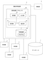
- FIG. 1 is a diagram illustrating the configuration of a position calculation device according to a first embodiment of the present invention.
- FIG. 1 is a diagram illustrating a traffic management system in which a traffic management device including a position calculation device according to a first embodiment is incorporated.
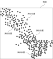
- FIG. 2 is an image diagram showing a flight position (positioned position) of an unmanned aircraft based on position information included in a remote ID transmitted from the unmanned aircraft.
- FIG. 3 is a diagram illustrating a method in which the position calculation device of the first embodiment calculates the flight position of an unmanned aircraft using position information included in a remote ID. Furthermore, it is a figure explaining the method by which the position calculation device of 1st Embodiment calculates the flight position of an unmanned aircraft using the position information contained in remote ID.
- FIG. 1 is a diagram illustrating the configuration of a position calculation device according to a first embodiment of the present invention.
- FIG. 1 is a diagram illustrating a traffic management system in which a traffic management device including a position calculation device
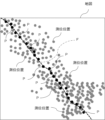
- FIG. 2 is a diagram illustrating an example of the flight position and flight trajectory of the unmanned aircraft calculated by the position calculation device of the first embodiment.
- 2 is a flowchart illustrating an example of an operation in which the position calculation device of the first embodiment calculates a flight position of an unmanned aircraft using position information included in a remote ID. It is a figure explaining the composition of the position calculation device of a 2nd embodiment.
- FIG. 2 is a diagram illustrating an embodiment in which a position calculation device is incorporated into a monitoring device. It is a figure explaining the composition of the position calculation device of other embodiments. It is a flow chart explaining an example of operation of a position calculation device of other embodiments.
- FIG. 1 is a diagram illustrating the configuration of a traffic management device including a position calculation device according to a first embodiment of the present invention.
- the operation management device 4 is a computer device that is incorporated into the operation management system 1 as shown in FIG. 2 and manages the operation of the unmanned aircraft 2.
- the unmanned aircraft 2 is an aircraft that has a structure that can be used for aviation purposes and can be flown by remote control or autopilot, and includes so-called drones and flying cars.
- the unmanned aircraft 2 transmits the remote ID at predetermined timings (eg, every 1 second) by wireless communication.
- the remote ID is identification information that identifies the unmanned aircraft 2 in flight, and includes aircraft unique information, position information, and time information.
- the aircraft-specific information is information that includes the aircraft-specific number given to each unmanned aircraft 2, and here, the registration number issued (assigned) when the aircraft is registered with the country is included as the aircraft-specific number. It will be done.
- the position information is information representing the flight position of the unmanned aircraft 2 (for example, latitude, longitude, and height information) obtained using GNSS (Global Navigation Satellite System).
- the time information is information representing the time at which information representing the flight position in the position information was acquired.
- Such aircraft-specific information, position information, and time information are associated and included in the remote ID.
- Bluetooth registered trademark
- the unmanned aircraft 2 as described above is a type of unmanned vehicle.
- An unmanned vehicle is a device, such as an unmanned aircraft or a self-driving car, that does not have an operator or driver on board and moves by remote control or autonomous control. Equipped with a function to transmit location information.
- the traffic management system 1 includes a plurality of receivers 3 and a traffic management device 4.
- the receiver 3 has a function of receiving a remote ID transmitted from the unmanned aircraft 2 and a function of transmitting the received remote ID to the operation management device 4.
- the configuration of the receiver 3 is not limited as long as it is capable of receiving a remote ID and can be connected to the traffic management device 4 via an information communication network; Description will be omitted.
- Such receivers 3 are installed at a plurality of locations determined in consideration of the predetermined route of the unmanned aircraft 2 and the like. Note that some of the plurality of receivers 3 that constitute the traffic management system 1 may be installed in a moving body.
- the receiver 3 may be installed in a vehicle such as a truck as an on-vehicle device, or may be a reception device realized by a processor that executes processing according to an application program and a communication device in a car navigation computer device, a mobile terminal, etc.
- a container 3 may be equipped.
- the traffic management device 4 includes a calculation device 40 and a storage device 50, as shown in FIG.
- the storage device 50 includes a storage medium that stores data and a computer program (hereinafter also referred to as a program) 51.
- a computer program hereinafter also referred to as a program
- RAM Random Access Memory
- ROM Read Only Memory
- the type of storage device 50 included in the traffic management device 4 is not limited to one type.
- Computer devices are often equipped with multiple types of storage devices.
- the type and number of storage devices 50 provided in the traffic management device 4 are not limited, and their explanation will be omitted.
- the traffic management device 4 is equipped with a plurality of types of storage devices 50, they are collectively referred to as the storage device 50.
- the storage device 50 contains a computer program for giving the flight control device 4 the function of managing the flight of the unmanned aircraft 2, and a computer program for calculating the flight position of the unmanned aircraft 2 from the position information included in the remote ID. Stores computer programs, etc.
- the arithmetic device 40 is composed of a processor such as a CPU (Central Processing Unit) or a GPU (Graphics Processing Unit).
- the arithmetic device 40 can have various functions based on the program 51 by reading and executing the program 51 stored in the storage device 50.
- the arithmetic device 40 includes an acquisition section 41, a management section 42, a determination section 43, and an output section 44 as functional sections.
- the position calculation device 5 is included in the traffic management device 4 and is configured by an acquisition unit 41 and a determination unit 43 of the arithmetic unit 40 that constitute the traffic management device 4, and a storage device 50. .
- the acquisition unit 41 has a function of acquiring, from each of the receivers 3, the remote ID that the receiver 3 receives from the unmanned aircraft 2.
- the information included in the received remote ID is associated with each other, and is held in the storage device 50 in a state in which, for example, receiver identification information for identifying the receiver 3 that has transmitted the information is further associated.
- the determination unit 43 selects a position that is likely to correspond to the actual flight position from among the position information (hereinafter also referred to as position position) of a plurality of remote IDs transmitted from the same unmanned aircraft 2 in flight and acquired by the acquisition unit 41. is determined as the flight position of the unmanned aircraft 2. Note that the flight position of the unmanned aircraft 2 determined by the determination unit 43 is used by the management unit 42 for operational management of the unmanned aircraft 2 during flight, so the flight position is determined while the unmanned aircraft 2 is in flight. They are executed sequentially at appropriate timings.
- FIG. 3 is an image diagram in which the position information (positioned position) of the remote ID transmitted from the same unmanned aircraft 2 is represented by a dot ( ⁇ ) on a map.
- the positioning positions are shown on the map, so it appears that the multiple positioning positions are located on the same plane along the ground, but the multiple positioning positions are located on the same plane along the ground. It also varies.
- the determining unit 43 determines (calculates) the flight position of the unmanned aircraft 2 as follows. That is, the flight plan and route reference information of the unmanned aircraft 2 are stored in advance in the storage device 50 or the database 7 to which the flight management device 4 is connected.
- the route reference information is information including information on the standard route pattern (movement pattern) of the unmanned aircraft 2.
- the information on the standard route pattern is obtained by processing a large number of flight trajectories based on the actual flight position of the unmanned aircraft 2 using, for example, radar or camera images, using statistical processing or AI (Artificial Intelligence). This information represents a route pattern that is most likely an unmanned aircraft.
- the flight speed of the unmanned aircraft 2, information on the weather of the airspace in which it flew, information on the time of flight, etc. may also be used to generate the standard route pattern.
- the information for calculating the standard route pattern using the flight speed of the unmanned aircraft 2, the weather information of the airspace in which it flew, and the information on the flight time may be different from the standard route pattern.
- the information may be included in route reference information.
- the information on the standard route pattern included in the route reference information stored in the storage device 50 or the database 7 is not limited to one, but, for example, there are multiple standard route patterns corresponding to each of the multiple models of the unmanned aircraft 2.
- information may be included.
- the route reference information may include information on a plurality of standard route patterns corresponding to each type of weather such as clear weather, strong winds, and rain.
- the route reference information may include information on a plurality of standard route patterns corresponding to a plurality of such combinations of aircraft types and weather.
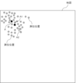
- the determination unit 43 determines one of the positioning positions of the plurality of remote IDs as shown in FIG. 4 transmitted from the aircraft of interest. Let us assume that we have focused on one position (also referred to as position A). It is assumed that this position of interest A is a likely position as the flight position of the aircraft of interest.
- the determination unit 43 selects among the plurality of positioning positions (selection candidates) associated with the aircraft-specific information of the aircraft of interest, with reference to the standard route pattern as described above and the flight plan of the aircraft of interest. , select a likely positioning position (for example, positioning position A1 in FIG. 4) as the flight position at which the aircraft of interest has advanced from position A of interest.
- a likely positioning position for example, positioning position A1 in FIG. 4
- the aircraft of interest unmanned aircraft 2 attempts to fly according to the flight route included in the flight plan, but in reality it may deviate from the flight route due to wind conditions in the flight area. . Therefore, here, not only the flight plan but also the standard route pattern is used to select a likely positioning position as the flight position of the aircraft of interest.
- the determining unit 43 determines the selected positioning position A1 as the flight position of the aircraft of interest.
- the positioning positions that are likely to be flight positions are selected from among the positioning positions of the selection candidates, for example, positioning positions within a range determined with respect to the position of interest A as a reference.
- An example of the range for determining the selection candidates is the direction in which the aircraft of interest is expected to move forward from the reference (position of interest A), and the distance that the aircraft of interest is expected to move forward in a predetermined time from the reference (position of interest A) (in other words, Then, the range defined by the speed of the aircraft of interest).
- the standard route pattern to be referenced may be a route pattern that takes into consideration the flight speed of the aircraft of interest and the weather of the flight area.
- the route reference information includes information on multiple standard route patterns corresponding to the flight speed of the unmanned aircraft 2 and weather conditions such as sunny, strong winds, and rain
- the route pattern corresponding to the flight speed of the aircraft 2 and the weather of the flight area is referred to.
- the following positioning position correction may be performed.
- the surrounding environment where the receiver 3 is installed such as an environment where there is a high-rise building nearby, next to a large river, or halfway up a mountain
- the remote ID cannot be acquired by the receiver 3.
- This can also be said to be the environment in which the unmanned aircraft 2 is flying. Therefore, the position information included in the remote ID received by the receiver 3 has an error depending on the radio wave reception status of the unmanned aircraft 2 due to the environment around the receiver 3 (the environment around the unmanned aircraft 2). is thought to be included.
- the main cause of the error in location information is an error caused by the environment as described above, for example, depending on the receiver 3, a similar positional shift may be observed in the location information of the received remote ID. Conceivable. In other words, the position information of the remote ID received by a certain receiver 3 tends to be shifted by about 700 meters in the west direction from the actual position of the unmanned aircraft 2. It is conceivable that this may be observed. Taking this into consideration, the position information (positioned position) of the remote ID received by the receiver 3 where such a positional deviation that can be estimated in advance is observed is corrected by the estimated positional deviation. The positioning position selection process described above may be performed using the corrected positioning position corrected in this manner.
- the determination unit 43 repeats the same process as described above using the determined flight position (positioned position A1) as the focused position, and determines, for example, the determined position A2 as shown in FIG. 5 as the flight position of the aircraft of interest.
- the location is selected as a likely location and confirmed as the flight location of the aircraft of interest.
- the determination unit 43 sequentially determines the likely flight position P of the aircraft of interest as shown in FIG. 6 as the flight position of the aircraft of interest. do.
- the processing start timing may be, for example, the timing when the number of acquired positioning positions is counted and the count number reaches a set number, or the timing when the positioning position is acquired (that is, every time a positioning position is acquired). ) or at set time intervals.
- the information on the likely flight position of the aircraft of interest determined as above includes, as confirmed flight position information, the aircraft-specific information of the aircraft of interest and the time information associated with the position information corresponding to the determined flight position. They are stored in the storage device 50 or database 7 in association with each other.
- the determining unit 43 utilizes the determined flight position P of the aircraft of interest and the time information associated with the position information corresponding to the flight position P, for example, as shown by the dotted line F in FIG.
- a flight trajectory (hereinafter also referred to as an estimated trajectory) of the aircraft of interest is calculated.
- This calculated information on the estimated trajectory of the aircraft of interest is stored in the storage device 50 or the database 7 in association with the aircraft-specific information of the aircraft of interest and flight date and time information.
- the determining unit 43 takes into account the new flight position P and determines the trajectory of the aircraft of interest. Update the estimated trajectory of the aircraft. This updated information regarding the estimated trajectory of the aircraft of interest is overwritten and stored in the storage device 50 or the database 7.
- the determination unit 43 determines the likely flight position of each of these unmanned aerial vehicles 2 from among the plurality of positioning positions as described above. The selected position is determined as the flight position of the unmanned aircraft 2. Further, the determination unit 43 calculates a flight trajectory (estimated trajectory) for each unmanned aircraft 2 using the determined flight position.
- the management unit 42 uses the confirmed flight position information including the flight position of the unmanned aircraft 2 confirmed by the confirming unit 43 to manage the operation of the unmanned aircraft 2 to be managed.
- the output unit 44 outputs the results of the processing by the management unit 42 from the arithmetic device 40 to a preset output destination.
- information on the flight plan of the unmanned aircraft 2 to be managed is stored in advance in the storage device 50 or the database 7 to which the flight management device 4 is connected.
- This flight plan information is associated with, for example, aircraft-specific information of the unmanned aircraft 2 that executes the flight plan.
- the system-specific aircraft identification number assigned to the unmanned aircraft 2 by the operation management system 1 in order to identify the unmanned aircraft 2 is associated with the flight plan. It may be.
- data representing the correspondence between the aircraft identification number and the aircraft unique information (registration number) is stored in the storage device 50, for example.
- the management unit 42 uses the aircraft-specific information of the remote ID acquired by the acquisition unit 41 to refer to the flight plan of the unmanned aircraft 2 corresponding to the aircraft-specific information in the storage device 50 or the database 7. Then, the management unit 42 compares the confirmed flight position information and flight trajectory (estimated trajectory) information provided by the confirmation unit 43 with the flight route (hereinafter also referred to as planned route) and scheduled flight time included in the flight plan, and It is determined whether the aircraft 2 is flying according to the flight plan. For example, the management unit 42 calculates the amount of deviation of the trajectory estimated by the determining unit 43 from the planned route, and determines whether the amount of deviation is within a predetermined allowable range.
- the management unit 42 executes predetermined countermeasure processing.
- the handling process may include controlling the flight of the unmanned aircraft 2 that deviates from the planned route in order to correct the flight route.
- the management unit 42 executes it.
- the output unit 44 outputs a control signal toward the unmanned aircraft 2 to be flight controlled.
- the flight control device 4 manages the flight of the unmanned aircraft 2 to be managed, but the flight control (operation) of the unmanned aircraft 2 is performed using a control system (GCS (Ground Control Station)) that is separate from the flight control device 4. may be executed by.
- GCS Global Control Station
- the operation management device 4 is connected to a GCS 8 as shown by the dotted line in FIG. 2, which performs flight control (operation) of the unmanned aircraft 2 to be managed.
- the management unit 42 may use the output unit 44 to notify the GCS 8 that is controlling the unmanned aircraft 2 that has deviated from the planned route, of the information that the unmanned aircraft 2 has deviated from the planned route.
- data that associates the unmanned aircraft 2 to be managed with information representing the GCS 8 that controls the unmanned aircraft 2 is stored in the storage device 50 or the database 7. has been done.
- the management unit 42 uses the confirmed flight position information by the confirmation unit 43 for each unmanned aircraft 2 to determine whether an unmanned aircraft is flying within a reporting range determined based on the flight position of the unmanned aircraft 2 that has deviated from the planned route. 2 is detected. Then, the management unit 42 notifies the GCS 8, which is controlling the flight of the detected unmanned aircraft 2, through the output unit 44, information that the unmanned aircraft 2 that has deviated from the planned route is flying nearby. You may. By the way, it is assumed that among the large number of remote IDs acquired by the acquisition unit 41 from the receiver 3, remote IDs transmitted from unmanned aircraft 2 other than those to be managed may be included.
- the database of a system related to the registration of unmanned aircraft serves as the information source 6 shown by the dotted line in Figure 1.
- the management unit 42 can obtain information on the contact information (connection destination) of the operator (GCS) associated with the remote ID transmitted from the unmanned aircraft 2 other than the one to be managed.
- the management unit 42 also notifies the pilot (GCS) who is controlling the flight of the unmanned aircraft 2 other than the one to be managed, of the information that the unmanned aircraft 2 that has deviated from the planned route is flying nearby. You may.
- the management unit 42 outputs, for example, information indicating that there is an unmanned aircraft 2 that has deviated from the planned route and its flight position to a predetermined manned aircraft by the output unit 44. You may also notify the control center or nearby facilities.
- FIG. 7 is a flowchart illustrating an example of the operation of the position calculation device 5.
- the acquisition unit 41 acquires the remote ID from the receiver 3 every moment, and the storage device 50 or the database 7 stores information on a plurality of positioning positions based on the remote ID from the aircraft of interest. do.
- the determination unit 43 detects that it is time to start processing, it extracts the positioning position of the selection candidate regarding the aircraft of interest from the positioning positions stored in the storage device 50 or the database 7 (see FIG. Step 101 in 7).
- the determination unit 43 refers to the standard route pattern and flight plan of the unmanned aircraft 2, selects a positioning position that is likely to be the flight position of the aircraft of interest from among the positioning positions of the selection candidates (step 102), and The selected positioning position is determined as the flight position of the aircraft of interest (step 103).
- This confirmed flight position information is stored in the storage device 50 or in a database in which aircraft-specific information of the aircraft of interest and time information associated with the position information corresponding to the confirmed flight position are associated with each other as confirmed flight position information. 7 is stored.
- the determining unit 43 updates the flight trajectory of the aircraft of interest in consideration of the determined flight position (step 104), and the updated flight trajectory is overwritten and stored in the storage device 50 or database 7.
- the position calculation device 5 of the first embodiment selects a positioning position that is likely to be the flight position of the unmanned aircraft 2 from among the positioning positions by referring to a standard route pattern that has been determined in advance and a flight plan.
- the selected position is determined as the flight position of the unmanned aircraft 2.
- the position calculation device 5 can calculate the flight position of the unmanned aircraft 2 while suppressing the adverse effects of variations in positioning positions caused by variations in errors. That is, the position calculation device 5 can improve the accuracy of the flight position of the unmanned aircraft 2 calculated using the position information included in the remote ID.
- the operation management device 4 uses the flight position and flight trajectory of the unmanned aircraft 2 determined (calculated) by the position calculation device 5 (determination unit 43) to remotely manage the operation of the unmanned aircraft 2. It is possible to suppress the occurrence of problems caused by the accuracy of ID location information.
- the determining unit 43 may further include the following functions. That is, even though the unmanned aerial vehicle 2 is flying, there may be a flight section in which the remote ID of the unmanned aerial vehicle 2 is not acquired. In such a case, the determination unit 43 refers to the standard route pattern (movement pattern) and flight plan to determine the flight trajectory of the unmanned aircraft 2 regarding the flight section for which no remote ID (location information) has been acquired. You can guess. In other words, the determining unit 43 may have a function of supplementing the flight trajectory of a flight section with missing data for which remote ID (location information) has not been acquired.
- the transmitter for transmitting the remote ID of the unmanned aircraft 2 may malfunction or the unmanned aircraft 2 may crash, making it impossible to obtain the remote ID from the unmanned aircraft 2.
- the determining unit 43 refers to the standard route pattern (movement pattern) and flight plan to estimate the crash position of the unmanned aircraft 2 and to estimate the crash position when the unmanned aircraft 2 continues to fly.
- the flight position of the unmanned aircraft 2 may also be estimated.
- the flight management device 4 can provide the crash position and continued flight position of the unmanned aircraft 2 to the pilot (GCS), for example, so that the crashed unmanned aircraft 2 and the transmitter can be This can contribute to the prompt recovery of the unmanned aircraft 2 that is out of order.
- GCS pilot
- the position calculation device 5 (traffic management device 4) has an update unit 45 as shown in FIG. It is equipped with Further, the position calculation device 5 (traffic management device 4) is capable of acquiring information from the detection device 9.
- the detection device 9 is a device (for example, a radar) that detects the flight position of the unmanned aircraft 2, and outputs information representing the detected flight position (hereinafter also referred to as a detected position).
- the update unit 45 is a functional unit realized by a processor executing a program.
- This updating unit 45 uses the information output from the detection device 9 to track the detected positions that are considered to be those of the same unmanned aircraft 2, thereby determining the actual flight trajectory (hereinafter also referred to as detected trajectory) of the unmanned aircraft 2. ) is calculated. Note that when the detected trajectory of the unmanned aircraft 2 is calculated by an information processing device 10 different from the position calculation device 5 (operation management device 4) using information output from the detection device 9, the update is performed.
- the unit 45 may acquire the detected trajectory of the unmanned aircraft 2 from the information processing device 10. In this case, the process of calculating the detected trajectory of the unmanned aircraft 2 by the updating unit 45 is omitted.
- the updating unit 45 further associates the detected trajectory that is considered to be of the same unmanned aircraft 2 with the estimated trajectory by the determining unit 43. Furthermore, the updating unit 45 compares the associated detected trajectory and estimated trajectory, and uses the comparison result to update the standard route pattern included in the route reference information by statistical processing or AI. .
- the configuration of the position calculation device 5 (traffic management device 4) in the second embodiment other than the above is the same as the configuration of the position calculation device 5 (traffic management device 4) in the first embodiment.
- the position calculation device 5 of the second embodiment has the same configuration as the position calculation device 5 of the first embodiment, it can achieve the same effects as the first embodiment. Furthermore, since the position calculation device 5 of the second embodiment updates the standard route pattern by the updating unit 45, it is possible to increase the likelihood of the unmanned aircraft 2 in the standard route pattern. The accuracy of the flight position of the unmanned aircraft 2 determined by 43 can be further improved.
- the present invention is not limited to the first and second embodiments, and can take various embodiments.
- the first and second embodiments show examples in which the position calculation device according to the present invention is applied to a traffic management device.
- the position calculation device described in the first and second embodiments can be applied to, for example, the following monitoring device.
- FIG. 9 is a diagram illustrating the configuration of a monitoring device 12 including a position calculation device 5 having a similar configuration to the position calculation device 5 described in the first and second embodiments.
- This monitoring device 12 is a device that monitors a predetermined monitoring airspace.
- the surveillance airspace may be set as appropriate, but a specific example is an airspace that requires permission to fly an unmanned aircraft. More specifically, the airspace that requires flight permission includes the airspace above and around important facilities such as airports, power plants, commercial facilities, stadiums, oil complexes, and government facilities. Further, specific examples of airspace that require flight permission include routes for unmanned aircraft, such as logistics-related unmanned aircraft, that have received permission to fly, corridors for aircraft other than unmanned aircraft, and the surrounding airspace.
- a plurality of receivers 3 that receive remote IDs transmitted from the unmanned aircraft 2 are arranged at appropriate positions and spaced apart from each other.
- the monitoring device 12 includes a calculation device 20 and a storage device 25.
- the storage device 25 includes a storage medium that stores data and programs 26, similar to the storage device 50 described in the first and second embodiments.
- the arithmetic device 20 is configured by a processor like the arithmetic device 40 described in the first and second embodiments, and when the processor executes the program 26, it can have various functions based on the program 26. .
- the arithmetic device 20 includes an acquisition unit 41 and a determination unit 43 that constitute the position calculation device 5 described in the first and second embodiments, and further includes a monitoring unit 21 and an output unit 22. ing.
- the arithmetic device 20 may include an update section 45 that constitutes the position calculation device 5.
- the functions of the acquisition unit 41, confirmation unit 43, and update unit 45 are similar to those of the acquisition unit 41, confirmation unit 43, and update unit 45 described in the first and second embodiments. The explanation thereof will be omitted here.
- the monitoring unit 21 uses the flight position of the unmanned aircraft 2 determined by the determining unit 43 to execute the following monitoring process.
- flight permission information is generated in advance and stored in the storage device 25 or the database 13 to which the monitoring device 12 is connected.
- the flight permission information includes information representing airplanes that are permitted to fly in the monitored airspace and their flight plans.
- the flight permission information includes the unique information of the unmanned aircraft 2 that is permitted to fly in the monitored airspace (in other words, the registration number of the aircraft given by registration with the country), and the unmanned aircraft 2.
- Information about the flight plan on which the aircraft 2 is permitted to fly is included in association with the information.
- the monitoring unit 21 detects that the flight position of the unmanned aircraft 2 determined by the determining unit 43 is in the monitored airspace (that is, intrusion into the monitored airspace), the monitoring unit 21 detects that the flight position of the unmanned aircraft 2 determined by the determining unit 43 is included in the remote ID transmitted from the unmanned aircraft 2.
- the aircraft-specific information included in the flight permission information is compared with the aircraft-specific information included in the flight permission information. As a result, if the aircraft specific information of the remote ID is included in the flight permission information, the monitoring unit 21 further refers to the flight plan associated with the aircraft specific information.
- the monitoring unit 21 determines whether the unmanned aircraft 2 flying in the monitored airspace is an unmanned aircraft 2 that is permitted to fly in the monitored airspace, and whether the flight is in accordance with the flight plan. Decide whether or not. As a result, if the monitoring unit 21 determines that the unmanned aircraft 2 that has been permitted to fly in the monitored airspace is flying according to the flight plan, it will continue to monitor the flight of the unmanned aircraft 2 in the monitored airspace. , no other processing is performed regarding the unmanned aircraft 2. For example, the output unit 22 outputs a message to a monitor viewed by an observer who is monitoring the surveillance airspace using the monitoring device 12, indicating that the unmanned aircraft 2 flying in the surveillance airspace is a licensed aircraft that is permitted to fly. Outputs information to notify that.
- the monitoring unit 21 determines that the unmanned aircraft 2 that transmitted the remote ID is a suspicious aircraft that is not permitted to fly in the monitored airspace. . Furthermore, the monitoring unit 21 obtains the estimated trajectory of the unauthorized suspicious aircraft (unmanned aerial vehicle 2) within the monitored airspace by the determining unit 43. Then, the monitoring unit 21 refers to a previously given intrusion purpose determination trajectory, and estimates the intrusion purpose of the suspicious aircraft from the obtained estimated trajectory. For example, the monitoring unit 21 estimates that the suspicious aircraft is flying toward a non-public area of an important facility in the monitored airspace based on the intrusion purpose determination trajectory.
- the monitoring unit 21 determines that the destination location of the suspicious aircraft in the monitored airspace cannot be identified even by referring to the intrusion purpose determination trajectory, the monitoring unit 21 estimates that the suspicious aircraft is an unmanned aircraft that has wandered into the monitored airspace. do.
- the monitoring unit 21 executes countermeasure processing according to the estimated purpose of the intrusion.
- the monitoring unit 21 uses the output unit 22 to notify the control system (GCS) that is controlling the flight of the suspicious aircraft to evacuate from the monitored airspace.
- GCS control system
- the monitoring unit 21 may further perform monitoring processing for unmanned aircraft that do not transmit a remote ID.
- the monitoring device 12 is connected to a sensing device 15 as represented by the dotted line in FIG.
- the detection device 15 is a device that detects an unmanned aircraft in a surveillance airspace, and is configured by, for example, a passive radar (radio wave detection sensor), a surveillance camera, a radar, a lidar, or a combination of two or more of them.
- the monitoring unit 21 refers to the information on the flight position of the unmanned aircraft 2 determined by the determining unit 43 and the detection information of the unmanned aircraft in the surveillance airspace obtained from the detection device 15, and determines whether the remote ID is not transmitted. It can detect when unmanned aircraft are flying in surveillance airspace. When the monitoring unit 21 detects that an unmanned aircraft that has not transmitted a remote ID, that is, a suspicious aircraft, is flying in the monitored airspace, it executes a predetermined countermeasure process. For example, the monitoring unit 21 uses the detection information of the unmanned aircraft output from the detection device 15 to calculate the flight trajectory of the suspicious aircraft in the monitored airspace.
- the monitoring unit 21 compares the calculated flight trajectory of the suspicious aircraft with the planned route included in the flight plan of the unmanned aircraft 2 that is permitted to fly, and compares the flight trajectory of the suspicious aircraft with a plan similar to the flight trajectory of the suspicious aircraft. Determine whether there is a route. As a result of this judgment, if there is a planned route similar to the flight trajectory of the suspicious aircraft, the monitoring unit 21 determines that although the suspicious aircraft is an unmanned aircraft that is permitted to fly in the monitored airspace, there is It is determined that the device 12 (position calculation device 5) has not been able to acquire the remote ID.
- the monitoring unit 21 may be able to obtain a remote ID for the control system (GCS) that is controlling the flight of the unmanned aircraft 2 corresponding to a planned route similar to the flight trajectory of the suspicious aircraft.
- the output unit 22 outputs information that there is no such information.
- the control system (GCS) performs, for example, checking the operation of the remote ID transmitter in the unmanned aircraft 2.
- the monitoring unit 21 determines that the suspicious aircraft is an unmanned aircraft that is not permitted to fly in the monitored airspace. Then, the monitoring unit 21 executes a predetermined countermeasure process for such a suspicious machine.
- countermeasures include preventing the suspicious aircraft from flying with laser irradiation, or forcing the suspicious aircraft to land by controlling the control device (computer) installed on the suspicious aircraft through hacking.
- control device computer
- the monitoring unit 21 may notify the manager of an important facility corresponding to the monitored airspace, etc., of the approaching suspicious aircraft through the output unit 22.
- the position calculation device 5 is shown as being incorporated in the traffic management device 4 and the monitoring device 12.
- the position calculation device 5 may be a single device, and the information on the flight position of the unmanned aircraft 2 determined by the single position calculation device 5 and the information on the flight trajectory are transmitted from the position calculation device 5. It may also be output to a traffic control device or a monitoring device.
- the position calculation device 5 is equipped with a function of providing residents and the GCS with information on the flight position of the unmanned aircraft 2 determined by the determination unit 43. Good too. That is, when a terminal device operated by a resident or a GCS connects to the position calculation device 5, and the terminal device requests the position calculation device 5 to provide information on the flight position of the unmanned aircraft 2, the position calculation device 5 In response to a request, it is provided with a function of returning, for example, the flight position of a specific unmanned aircraft 2 or the flight position of an unmanned aircraft 2 flying in a specific airspace. Further, the position calculation device 5 may periodically provide information on the flight position of the unmanned aircraft 2 to pre-registered residents and GCS terminal devices.
- the position calculation device 5 calculates the flight position of the unmanned aircraft 2. It can also be applied to unmanned moving objects such as cars. Furthermore, in the embodiments described above, when selecting a likely positioning position as the position of an unmanned aircraft (unmanned moving object), standard route patterns (travel patterns) and flight plans (operation plans) are referred to. Instead, for example, if the flight plan (operation plan) cannot be referenced for some reason and the route of unmanned aircraft (unmanned moving vehicles) is regulated, the most likely positioning It is not necessary to use a flight plan (operation plan) to select a location.
- FIG. 10 is a block diagram illustrating the minimum configuration of the position calculation device according to the present invention.
- the position calculation device 30 in FIG. 10 includes an acquisition section 31 and a determination section 32.
- the acquisition unit 31 acquires identification information transmitted from the unmanned vehicle at predetermined transmission timings.
- the identification information includes body-specific information given to the unmanned moving object, position information representing the position of the unmanned moving object, and time information.
- the determination unit 32 uses a standard movement pattern given in advance from among the measured positions that are the positions of the unmanned moving objects represented by the position information included in each of the plurality of pieces of acquired identification information. Then, a likely position is selected as the position of the unmanned vehicle.
- the determining unit 32 determines the selected positioning position as the position of the unmanned vehicle.
- FIG. 11 is a flowchart illustrating an example of the operation of the position calculation device 30 related to calculation of the position of the unmanned moving object.
- the acquisition unit 31 of the position calculation device 30 acquires identification information transmitted from an unmanned vehicle at each predetermined transmission timing, for example, via a receiver (step 201 in FIG. 11).
- the determination unit 32 selects a predetermined standard movement pattern from among the measured positions that are the positions of the unmanned moving objects represented by the position information included in each of the plurality of pieces of acquired identification information. Using this, a likely measured position is selected as the position of the unmanned vehicle (step 202).
- the determining unit 32 determines the selected positioning position as the position of the unmanned vehicle (step 203).
- the position calculation device 30 determines the position of the unmanned moving object with the above-described configuration and operation, it calculates the position of the unmanned moving object using the position information transmitted from the unmanned moving object. Calculation accuracy can be improved.
Landscapes
- Engineering & Computer Science (AREA)
- Radar, Positioning & Navigation (AREA)
- Remote Sensing (AREA)
- Physics & Mathematics (AREA)
- General Physics & Mathematics (AREA)
- Aviation & Aerospace Engineering (AREA)
- Automation & Control Theory (AREA)
- Computer Networks & Wireless Communication (AREA)
- Traffic Control Systems (AREA)
Priority Applications (2)
| Application Number | Priority Date | Filing Date | Title |
|---|---|---|---|
| PCT/JP2022/014391 WO2023181349A1 (ja) | 2022-03-25 | 2022-03-25 | 位置算出装置、位置算出方法およびプログラム記憶媒体 |
| JP2024509653A JP7768350B2 (ja) | 2022-03-25 | 2022-03-25 | 位置算出装置、位置算出方法およびコンピュータプログラム |
Applications Claiming Priority (1)
| Application Number | Priority Date | Filing Date | Title |
|---|---|---|---|
| PCT/JP2022/014391 WO2023181349A1 (ja) | 2022-03-25 | 2022-03-25 | 位置算出装置、位置算出方法およびプログラム記憶媒体 |
Publications (1)
| Publication Number | Publication Date |
|---|---|
| WO2023181349A1 true WO2023181349A1 (ja) | 2023-09-28 |
Family
ID=88100767
Family Applications (1)
| Application Number | Title | Priority Date | Filing Date |
|---|---|---|---|
| PCT/JP2022/014391 Ceased WO2023181349A1 (ja) | 2022-03-25 | 2022-03-25 | 位置算出装置、位置算出方法およびプログラム記憶媒体 |
Country Status (2)
| Country | Link |
|---|---|
| JP (1) | JP7768350B2 (https=) |
| WO (1) | WO2023181349A1 (https=) |
Cited By (1)
| Publication number | Priority date | Publication date | Assignee | Title |
|---|---|---|---|---|
| WO2026034516A1 (ja) * | 2024-08-05 | 2026-02-12 | 株式会社 東芝 | 統合対処システム、統合装置、および、飛行体対処方法 |
Citations (4)
| Publication number | Priority date | Publication date | Assignee | Title |
|---|---|---|---|---|
| JP2006125876A (ja) * | 2004-10-26 | 2006-05-18 | Alpine Electronics Inc | 移動体の位置算出装置および算出方法 |
| WO2018110634A1 (ja) * | 2016-12-14 | 2018-06-21 | 株式会社自律制御システム研究所 | 無人航空機の飛行管理システム、及び飛行管理方法 |
| WO2020255796A1 (ja) * | 2019-06-18 | 2020-12-24 | 日本電気株式会社 | 受信端末、測位方法及びプログラム |
| JP6883155B1 (ja) * | 2021-01-06 | 2021-06-09 | Kddi株式会社 | 飛行管理装置及び飛行管理方法 |
-
2022
- 2022-03-25 WO PCT/JP2022/014391 patent/WO2023181349A1/ja not_active Ceased
- 2022-03-25 JP JP2024509653A patent/JP7768350B2/ja active Active
Patent Citations (4)
| Publication number | Priority date | Publication date | Assignee | Title |
|---|---|---|---|---|
| JP2006125876A (ja) * | 2004-10-26 | 2006-05-18 | Alpine Electronics Inc | 移動体の位置算出装置および算出方法 |
| WO2018110634A1 (ja) * | 2016-12-14 | 2018-06-21 | 株式会社自律制御システム研究所 | 無人航空機の飛行管理システム、及び飛行管理方法 |
| WO2020255796A1 (ja) * | 2019-06-18 | 2020-12-24 | 日本電気株式会社 | 受信端末、測位方法及びプログラム |
| JP6883155B1 (ja) * | 2021-01-06 | 2021-06-09 | Kddi株式会社 | 飛行管理装置及び飛行管理方法 |
Cited By (1)
| Publication number | Priority date | Publication date | Assignee | Title |
|---|---|---|---|---|
| WO2026034516A1 (ja) * | 2024-08-05 | 2026-02-12 | 株式会社 東芝 | 統合対処システム、統合装置、および、飛行体対処方法 |
Also Published As
| Publication number | Publication date |
|---|---|
| JP7768350B2 (ja) | 2025-11-12 |
| JPWO2023181349A1 (https=) | 2023-09-28 |
Similar Documents
| Publication | Publication Date | Title |
|---|---|---|
| US12066840B2 (en) | Method and system for providing route of unmanned air vehicle | |
| US11900823B2 (en) | Systems and methods for computing flight controls for vehicle landing | |
| US20260008487A1 (en) | Unmanned aerial vehicle system for inspecting railroad assets | |
| US11927677B2 (en) | Systems and methods for supplemental navigation using distributed avionics processing | |
| US20210358311A1 (en) | Automated system of air traffic control (atc) for at least one unmanned aerial vehicle (uav) | |
| US12067889B2 (en) | Systems and methods for detect and avoid system for beyond visual line of sight operations of urban air mobility in airspace | |
| KR102752939B1 (ko) | 무인 비행체 항로 구축 방법 및 시스템 | |
| US12518637B2 (en) | Systems and methods for strategic smart route planning service for urban airspace users | |
| EP3866138A1 (en) | Systems and methods for automated cross-vehicle navigation using sensor data fusion | |
| KR20170111921A (ko) | 무인 비행체 제어 방법 및 시스템 | |
| JP7253315B2 (ja) | 航空機の飛行支援システム、航空機の飛行支援プログラム及び航空機 | |
| KR20170126637A (ko) | 무인 비행체 항로 구축 방법 및 시스템 | |
| EP3816649A1 (en) | Systems and methods for supplemental navigation using distributed avionics processing | |
| CN111819610A (zh) | 用于无人驾驶飞行器和载人飞行器的空中态势信息和交通管理系统 | |
| US20230282121A1 (en) | Displaying electromagnetic spectrum information for unmanned aerial vehicle (uav) navigation | |
| US11719783B2 (en) | Systems and methods for cross-reference navigation using low latency communications | |
| EP4063987A1 (en) | Systems and methods for identifying landing zones for unmanned aircraft | |
| JP7768350B2 (ja) | 位置算出装置、位置算出方法およびコンピュータプログラム | |
| RU2847508C1 (ru) | Способ обеспечения пилотирования бпла в общем воздушном пространстве | |
| EP3968056B1 (en) | Systems and methods for cross-reference navigation using low latency communications | |
| WO2023175810A1 (ja) | 無人航空機の情報取得システムおよび無人航空機の情報取得方法 |
Legal Events
| Date | Code | Title | Description |
|---|---|---|---|
| 121 | Ep: the epo has been informed by wipo that ep was designated in this application |
Ref document number: 22933489 Country of ref document: EP Kind code of ref document: A1 |
|
| ENP | Entry into the national phase |
Ref document number: 2024509653 Country of ref document: JP Kind code of ref document: A |
|
| NENP | Non-entry into the national phase |
Ref country code: DE |
|
| 122 | Ep: pct application non-entry in european phase |
Ref document number: 22933489 Country of ref document: EP Kind code of ref document: A1 |