WO2023181178A1 - Information processing device, information processing method, and program - Google Patents
Information processing device, information processing method, and program Download PDFInfo
- Publication number
- WO2023181178A1 WO2023181178A1 PCT/JP2022/013534 JP2022013534W WO2023181178A1 WO 2023181178 A1 WO2023181178 A1 WO 2023181178A1 JP 2022013534 W JP2022013534 W JP 2022013534W WO 2023181178 A1 WO2023181178 A1 WO 2023181178A1
- Authority
- WO
- WIPO (PCT)
- Prior art keywords
- customization process
- axis
- parameter
- control unit
- temperature
- Prior art date
Links
- 230000010365 information processing Effects 0.000 title claims abstract description 34
- 238000003672 processing method Methods 0.000 title claims description 5
- 238000000034 method Methods 0.000 claims abstract description 260
- 230000008569 process Effects 0.000 claims abstract description 244
- 238000010438 heat treatment Methods 0.000 claims abstract description 153
- 239000000443 aerosol Substances 0.000 claims abstract description 74
- 230000008859 change Effects 0.000 claims abstract description 60
- 239000000463 material Substances 0.000 claims description 33
- 238000012545 processing Methods 0.000 claims description 21
- 239000000796 flavoring agent Substances 0.000 abstract description 13
- 235000019634 flavors Nutrition 0.000 abstract description 13
- 230000007246 mechanism Effects 0.000 abstract description 4
- 239000000758 substrate Substances 0.000 abstract description 4
- 238000010586 diagram Methods 0.000 description 22
- 238000004891 communication Methods 0.000 description 19
- 230000000391 smoking effect Effects 0.000 description 13
- 230000006870 function Effects 0.000 description 9
- 238000001514 detection method Methods 0.000 description 8
- 230000005674 electromagnetic induction Effects 0.000 description 6
- 230000007704 transition Effects 0.000 description 5
- 239000000126 substance Substances 0.000 description 4
- DNIAPMSPPWPWGF-UHFFFAOYSA-N Propylene glycol Chemical compound CC(O)CO DNIAPMSPPWPWGF-UHFFFAOYSA-N 0.000 description 3
- 230000006698 induction Effects 0.000 description 3
- 230000001007 puffing effect Effects 0.000 description 3
- PEDCQBHIVMGVHV-UHFFFAOYSA-N Glycerine Chemical compound OCC(O)CO PEDCQBHIVMGVHV-UHFFFAOYSA-N 0.000 description 2
- 241000208125 Nicotiana Species 0.000 description 2
- 235000002637 Nicotiana tabacum Nutrition 0.000 description 2
- 230000001133 acceleration Effects 0.000 description 2
- 230000009471 action Effects 0.000 description 2
- 230000007423 decrease Effects 0.000 description 2
- 239000011810 insulating material Substances 0.000 description 2
- 238000009413 insulation Methods 0.000 description 2
- 239000007788 liquid Substances 0.000 description 2
- 238000009688 liquid atomisation Methods 0.000 description 2
- HBBGRARXTFLTSG-UHFFFAOYSA-N Lithium ion Chemical compound [Li+] HBBGRARXTFLTSG-UHFFFAOYSA-N 0.000 description 1
- 238000013459 approach Methods 0.000 description 1
- 238000004364 calculation method Methods 0.000 description 1
- 239000003086 colorant Substances 0.000 description 1
- 238000004590 computer program Methods 0.000 description 1
- 239000003814 drug Substances 0.000 description 1
- 229940079593 drug Drugs 0.000 description 1
- 230000000694 effects Effects 0.000 description 1
- 239000003571 electronic cigarette Substances 0.000 description 1
- 238000005516 engineering process Methods 0.000 description 1
- 235000011187 glycerol Nutrition 0.000 description 1
- 239000008263 liquid aerosol Substances 0.000 description 1
- 229910001416 lithium ion Inorganic materials 0.000 description 1
- 238000012986 modification Methods 0.000 description 1
- 230000004048 modification Effects 0.000 description 1
- 239000006199 nebulizer Substances 0.000 description 1
- 230000003287 optical effect Effects 0.000 description 1
- 230000000750 progressive effect Effects 0.000 description 1
- 230000004044 response Effects 0.000 description 1
- 239000007787 solid Substances 0.000 description 1
- 150000005846 sugar alcohols Polymers 0.000 description 1
- 239000013589 supplement Substances 0.000 description 1
- 238000012546 transfer Methods 0.000 description 1
- XLYOFNOQVPJJNP-UHFFFAOYSA-N water Substances O XLYOFNOQVPJJNP-UHFFFAOYSA-N 0.000 description 1
Images


Classifications
-
- A—HUMAN NECESSITIES
- A24—TOBACCO; CIGARS; CIGARETTES; SIMULATED SMOKING DEVICES; SMOKERS' REQUISITES
- A24F—SMOKERS' REQUISITES; MATCH BOXES; SIMULATED SMOKING DEVICES
- A24F40/00—Electrically operated smoking devices; Component parts thereof; Manufacture thereof; Maintenance or testing thereof; Charging means specially adapted therefor
- A24F40/50—Control or monitoring
- A24F40/57—Temperature control
-
- A—HUMAN NECESSITIES
- A24—TOBACCO; CIGARS; CIGARETTES; SIMULATED SMOKING DEVICES; SMOKERS' REQUISITES
- A24F—SMOKERS' REQUISITES; MATCH BOXES; SIMULATED SMOKING DEVICES
- A24F40/00—Electrically operated smoking devices; Component parts thereof; Manufacture thereof; Maintenance or testing thereof; Charging means specially adapted therefor
- A24F40/60—Devices with integrated user interfaces
Definitions
- the present invention relates to an information processing device, an information processing method, and a program.
- a suction device generates an aerosol to which a flavor component has been added using a base material that includes an aerosol source for generating an aerosol, a flavor source for imparting a flavor component to the generated aerosol, and the like.
- the user can taste the flavor by inhaling the aerosol to which the flavor component is added, which is generated by the suction device.
- the action of the user inhaling an aerosol will also be referred to below as a puff or a puff action.
- Patent Document 1 it may be difficult for the user to customize the device as desired.
- an object of the present invention is to provide a customization mechanism that allows the user to easily achieve the desired smoking taste.
- an aerosol is generated by heating an aerosol source included in a base material based on control information that defines parameters regarding the temperature at which the aerosol source is heated. generating a display image displaying an operation target for setting the parameter included in the control information used by the suction device; and a user operation on the operation target displayed in the generated display image. a control unit that controls a customization process including changing the parameters included in the control information according to the control information; An information processing apparatus is provided, which sets a method for changing the parameters in the next customization process based on the content of the changes in the parameters.
- the display image includes an axis on which the operation target is movably arranged, and the control unit changes the parameters based on the position of the operation target on the axis in the customization process, and changes the parameters based on the position of the operation target on the axis in the customization process, Based on the changes to the parameters in the process, a correspondence relationship between the position on the axis in the next customization process and the value set as the parameter when the operation target is located at the position may be set. good.
- control unit adds or subtracts a second value corresponding to a difference between the reference position and the operation target position to a first value corresponding to the reference position on the axis.
- a second value corresponding to a difference between the reference position and the operation target position may be set as the parameter
- the first value in the next customization process may be set based on the parameter set in the previous customization process.
- the control unit may set the parameter set in the previous customization process to the first value in the next customization process.
- control unit adds or subtracts a second value corresponding to a distance between the reference position and the operation target position to a first value corresponding to the reference position on the axis.
- a second value corresponding to a distance between the reference position and the operation target position may be set as the parameter
- the second value per unit distance in the next customization process may be set based on the amount of change in the parameter in the previous customization process.
- the control unit sets the second value per unit distance in the next customization process to be larger as the amount of change in the parameter in the previous customization process is larger, and the control unit sets the second value per unit distance in the next customization process to a larger value, The smaller the amount, the smaller the second value per unit distance may be set in the next customization process.
- the control unit adjusts the unit in the next customization process so that an integral multiple of the second value per unit distance in the next customization process matches the change amount of the parameter in the previous customization process.
- the second value per distance may be set.
- the initial position of the operation target in the display image may be the reference position on the axis.
- the reference position may be the center of the axis.
- the display image includes a plurality of the axes, each of the plurality of axes corresponds to each of the plurality of puff timings, and the control unit, based on the position of the operation target on each of the plurality of axes, The parameters may be set for each of the plurality of puff timings.
- the control unit is configured to cause, in the display image, a display mode of a portion of the axis that corresponds to a value that can be set as the parameter to be different from a display mode of a portion of the axis that corresponds to a value that cannot be set. Good too.
- an aerosol source included in a base material is heated based on control information that defines a parameter regarding the temperature at which the aerosol source is heated.
- generating a display image that displays an operation target for setting the parameter included in the control information used by a suction device that generates an aerosol; and controlling a customization process including changing the parameters included in the control information in response to a user operation, and controlling the customization process includes: when repeatedly executing the customization process;
- An information processing method is provided that includes setting a method for changing the parameters in the next customization process based on changes to the parameters in the previous customization process.
- the computer heats the aerosol source included in the base material based on control information that defines parameters regarding the temperature at which the aerosol source is heated.
- a program is provided that sets a method for changing the parameters in the next customization process based on the changes to the parameters in the previous customization process.
- a customization mechanism is provided that allows the user to easily achieve the desired smoking taste.
- FIG. 1 is a diagram for explaining an example configuration of a system according to an embodiment.
- FIG. 1 is a schematic diagram schematically showing a configuration example of a suction device according to the present embodiment.
- FIG. 2 is a block diagram showing a configuration example of a terminal device according to the present embodiment.
- 3 is a graph schematically showing an example of a heating profile. It is a figure showing an example of a customization screen concerning this embodiment.
- FIG. 7 is a diagram showing the correspondence between the position on the axis and the temperature in the next customization process when the target temperature has been raised in the previous customization process.
- FIG. 7 is a diagram showing the correspondence between the position on the axis and the temperature in the next customization process when the target temperature has been lowered in the previous customization process.
- FIG. 1 is a diagram for explaining an example configuration of a system according to an embodiment.
- FIG. 1 is a schematic diagram schematically showing a configuration example of a suction device according to the present embodiment.
- FIG. 2 is a
- FIG. 7 is a diagram for explaining a first specific example of updating the correspondence between the scale of the axis 32 and the temperature corresponding to one puff timing.
- FIG. 7 is a diagram for explaining a second specific example of updating the correspondence between the scale of the axis 32 and the temperature corresponding to one puff timing.
- FIG. 7 is a diagram for explaining a third specific example of updating the correspondence between the scale of the axis 32 and the temperature corresponding to one puff timing.
- FIG. 7 is a diagram for explaining a fourth specific example of updating the correspondence between the scale of the axis 32 and the temperature corresponding to one puff timing. It is a flowchart which shows an example of the flow of processing performed in the terminal device concerning this embodiment.
- FIG. 6 is a diagram for explaining the target temperature at the second puff timing.
- FIG. 1 is a diagram for explaining a configuration example of a system 1 according to an embodiment. As shown in FIG. 1, the system 1 includes a suction device 100 and a terminal device 200.
- the suction device 100 is a device that generates a substance to be suctioned by a user.
- the substance generated by the suction device 100 will be described as an aerosol.
- the substance produced by the suction device may be a gas.
- the suction device 100 uses a stick-type base material 150 to generate an aerosol.
- Stick type substrate 150 is an example of a substrate containing an aerosol source.
- the suction device 100 is an example of an aerosol generation device that generates aerosol by heating an aerosol source contained in a base material.
- the terminal device 200 is an information processing device that performs various information processing regarding the suction device 100.
- the terminal device 200 is used by the user of the suction device 100.
- the terminal device 200 may be any device such as a smartphone, a tablet terminal, a wearable device, or a PC (Personal Computer).
- the terminal device 200 may be a charger that charges the suction device 100.
- the terminal device 200 is used to change the settings of the suction device 100.
- the terminal device 200 receives a user operation for changing the settings of the suction device 100, and changes the settings of the suction device 100.
- FIG. 2 is a schematic diagram schematically showing a configuration example of the suction device according to the present embodiment.
- the suction device 100 includes a power supply section 111, a sensor section 112, a notification section 113, a storage section 114, a communication section 115, a control section 116, a heating section 121, a holding section 140, and a heat insulation section 144. .
- the power supply unit 111 stores power. Then, the power supply unit 111 supplies power to each component of the suction device 100 based on control by the control unit 116.
- the power supply unit 111 may be configured with a rechargeable battery such as a lithium ion secondary battery, for example.
- the sensor unit 112 acquires various information regarding the suction device 100.
- the sensor unit 112 includes a pressure sensor such as a condenser microphone, a flow rate sensor, a temperature sensor, etc., and acquires a value associated with suction by the user.
- the sensor unit 112 is configured with an input device such as a button or a switch that receives information input from the user.
- the notification unit 113 notifies the user of information.
- the notification unit 113 includes, for example, a light emitting device that emits light, a display device that displays an image, a sound output device that outputs sound, a vibration device that vibrates, or the like.
- the storage unit 114 stores various information for the operation of the suction device 100.
- the storage unit 114 is configured by, for example, a nonvolatile storage medium such as a flash memory.
- the communication unit 115 is a communication interface that can perform communication compliant with any wired or wireless communication standard.
- a communication standard for example, a standard using Wi-Fi (registered trademark), Bluetooth (registered trademark), NFC (Near Field Communication), or LPWA (Low Power Wide Area) may be adopted.
- the control unit 116 functions as an arithmetic processing device and a control device, and controls overall operations within the suction device 100 according to various programs.
- the control unit 116 is realized by, for example, an electronic circuit such as a CPU (Central Processing Unit) or a microprocessor.
- the holding part 140 has an internal space 141 and holds the stick-type base material 150 while accommodating a part of the stick-type base material 150 in the internal space 141.
- the holding part 140 has an opening 142 that communicates the internal space 141 with the outside, and holds the stick-shaped base material 150 inserted into the internal space 141 through the opening 142.
- the holding part 140 is a cylindrical body having an opening 142 and a bottom part 143 as the bottom surface, and defines a columnar internal space 141.
- An air flow path that supplies air to the internal space 141 is connected to the holding portion 140 .
- An air inflow hole which is an inlet of air to the air flow path, is arranged on a side surface of the suction device 100, for example.
- An air outlet hole which is an outlet for air from the air flow path to the internal space 141, is arranged at the bottom 143, for example.
- the stick-type base material 150 includes a base portion 151 and a mouthpiece portion 152.
- Base portion 151 includes an aerosol source.
- Aerosol sources are, for example, polyhydric alcohols such as glycerin and propylene glycol, and liquids such as water.
- the aerosol source may include flavor components of tobacco or non-tobacco origin. If the suction device 100 is a medical inhaler, such as a nebulizer, the aerosol source may include a drug. Note that in this configuration example, the aerosol source is not limited to a liquid, and may be a solid.
- the heating unit 121 atomizes the aerosol source to generate aerosol by heating the aerosol source.
- the heating section 121 is configured in a film shape and is arranged to cover the outer periphery of the holding section 140.
- the heating part 121 generates heat
- the base material part 151 of the stick-type base material 150 is heated from the outer periphery, and an aerosol is generated.
- the heating unit 121 generates heat when supplied with power from the power supply unit 111 .
- power may be supplied when the sensor unit 112 detects that the user has started suctioning and/or that predetermined information has been input. Then, when the sensor unit 112 detects that the user has finished suctioning and/or that predetermined information has been input, the power supply may be stopped.
- the heat insulating section 144 prevents heat transfer from the heating section 121 to other components.
- the heat insulating section 144 is made of a vacuum heat insulating material, an airgel heat insulating material, or the like.
- suction device 100 has been described above.
- the configuration of the suction device 100 is not limited to the above, and may take various configurations as exemplified below.
- the heating unit 121 may be configured in a blade shape and arranged to protrude from the bottom 143 of the holding unit 140 into the internal space 141. In that case, the blade-shaped heating unit 121 is inserted into the base portion 151 of the stick-type base material 150 and heats the base portion 151 of the stick-type base material 150 from inside.
- the heating part 121 may be arranged to cover the bottom part 143 of the holding part 140.
- the heating section 121 is a combination of two or more of a first heating section that covers the outer periphery of the holding section 140 , a second heating section shaped like a blade, and a third heating section that covers the bottom 143 of the holding section 140 . It may be configured as
- the holding part 140 may include an opening/closing mechanism such as a hinge that opens and closes a part of the outer shell that forms the internal space 141.
- the holding part 140 may hold the stick-shaped base material 150 inserted into the internal space 141 by opening and closing the outer shell.
- the heating unit 121 may be provided at the relevant clamping location in the holding unit 140 and may heat the stick-shaped base material 150 while pressing it.
- the means for atomizing the aerosol source is not limited to heating by the heating unit 121.
- the means of atomizing the aerosol source may be induction heating.
- the suction device 100 includes at least an electromagnetic induction source such as a coil that generates a magnetic field instead of the heating unit 121.
- the susceptor that generates heat by induction heating may be provided in the suction device 100 or may be included in the stick-shaped base material 150.
- the suction device 100 works together with the stick-shaped base material 150 to generate an aerosol that is suctioned by the user. Therefore, the combination of the suction device 100 and the stick-type base material 150 may be regarded as an aerosol generation system.
- FIG. 3 is a block diagram showing a configuration example of the terminal device 200 according to the present embodiment.
- the terminal device 200 includes an input section 210, an output section 220, a detection section 230, a communication section 240, a storage section 250, and a control section 260.
- the input unit 210 has a function of accepting input of various information.
- Input unit 210 may include an input device that accepts information input from a user. Examples of the input device include buttons, keyboards, touch panels, and microphones.
- the input unit 210 may include various sensors such as an image sensor.
- the output unit 220 has a function of outputting information.
- the output unit 220 may include an output device that outputs information to the user.
- Examples of the output device include a display device that displays information, a light emitting device that emits light, a vibration device that vibrates, and a sound output device that outputs sound.
- An example of a display device is a display.
- An example of a light emitting device is an LED (Light Emitting Diode).
- An example of a vibrating device is an eccentric motor.
- An example of a sound output device is a speaker.
- the output unit 220 notifies the user of the information by outputting the information input from the control unit 260.
- the detection unit 230 has a function of detecting information regarding the terminal device 200.
- the detection unit 230 may detect position information of the terminal device 200.
- the detection unit 230 receives a GNSS signal from a GNSS (Global Navigation Satellite System) satellite (e.g., a GPS signal from a GPS (Global Positioning System) satellite) and detects position information consisting of latitude and longitude of the device. do.
- the detection unit 230 may detect the movement of the terminal device 200.
- the detection unit 230 includes a gyro sensor and an acceleration sensor, and detects angular velocity and acceleration.
- the communication unit 240 is a communication interface for transmitting and receiving information between the terminal device 200 and other devices.
- the communication unit 240 performs communication based on any wired or wireless communication standard. Examples of such communication standards include standards using USB (Universal Serial Bus), Wi-Fi (registered trademark), Bluetooth (registered trademark), NFC (Near Field Communication), or LPWA (Low Power Wide Area). can be done.
- USB Universal Serial Bus
- Wi-Fi registered trademark
- Bluetooth registered trademark
- NFC Near Field Communication
- LPWA Low Power Wide Area
- the storage unit 250 stores various information.
- the storage unit 250 is configured by, for example, a nonvolatile storage medium such as a flash memory.
- the control unit 260 functions as an arithmetic processing device or a control device, and controls overall operations within the terminal device 200 according to various programs.
- the control unit 260 is realized by, for example, an electronic circuit such as a CPU (Central Processing Unit) or a microprocessor.
- the control unit 260 may include a ROM (Read Only Memory) that stores programs to be used, calculation parameters, etc., and a RAM (Random Access Memory) that temporarily stores parameters that change as appropriate.
- the terminal device 200 executes various processes based on control by the control unit 260.
- the control unit 260 processes information input by the input unit 210, outputs the information by the output unit 220, detects the information by the detection unit 230, transmits and receives information by the communication unit 240, and stores and reads information by the storage unit 250. This is an example of processing controlled by. Other processes executed by the terminal device 200, such as inputting information to each component and processing based on information output from each component, are also controlled by the control unit 260.
- control unit 260 may be realized using an application.
- the application may be preinstalled or may be downloaded. Further, the functions of the control unit 260 may be realized by PWA (Progressive Web Apps).
- the control unit 116 controls the operation of the heating unit 121 based on the heating profile. Control of the operation of the heating section 121 is achieved by controlling power supply from the power supply section 111 to the heating section 121. The heating unit 121 heats the stick-shaped base material 150 using the electric power supplied from the power supply unit 111.
- the heating profile is control information for controlling the temperature at which the aerosol source is heated.
- the heating profile defines parameters regarding the temperature at which the aerosol source is heated.
- An example of the temperature at which the aerosol source is heated is the temperature of the heating section 121.
- An example of a parameter related to the temperature at which the aerosol source is heated is a target value for the temperature of the heating section 121 (hereinafter also referred to as target temperature).
- the temperature of the heating unit 121 may be controlled to change depending on the elapsed time from the start of heating. In that case, the heating profile includes information that defines the time series transition of the target temperature.
- the heating profile may include parameters (hereinafter also referred to as power supply parameters) that define a method of supplying power to the heating unit 121.
- the power supply parameters include, for example, the voltage applied to the heating unit 121, ON/OFF of power supply to the heating unit 121, the feedback control method to be adopted, and the like. Turning on/off the power supply to the heating unit 121 may be regarded as turning the heating unit 121 on/off.
- the control unit 116 controls the operation of the heating unit 121 so that the temperature of the heating unit 121 (hereinafter also referred to as actual temperature) changes in the same manner as the target temperature defined in the heating profile.
- the heating profile is typically designed to optimize the flavor experienced by the user when the user inhales the aerosol generated from the stick-shaped substrate 150. Therefore, by controlling the operation of the heating unit 121 based on the heating profile, the flavor that the user enjoys can be optimized.
- Temperature control of the heating section 121 can be realized, for example, by known feedback control.
- the feedback control may be, for example, PID control (Proportional-Integral-Differential Controller).
- the control unit 116 can cause the power from the power supply unit 111 to be supplied to the heating unit 121 in the form of pulses using pulse width modulation (PWM) or pulse frequency modulation (PFM). In that case, the control unit 116 can control the temperature of the heating unit 121 by adjusting the duty ratio or frequency of the power pulse in feedback control. Alternatively, the control unit 116 may perform simple on/off control in feedback control.
- control unit 116 causes the heating unit 121 to perform heating until the actual temperature reaches the target temperature, and when the actual temperature reaches the target temperature, interrupts the heating by the heating unit 121 so that the actual temperature is lower than the target temperature. When the temperature becomes low, heating by the heating unit 121 may be restarted.
- the temperature of the heating section 121 can be quantified, for example, by measuring or estimating the electrical resistance value of the heating section 121 (more precisely, the heating resistor that constitutes the heating section 121). This is because the electrical resistance value of the heating resistor changes depending on the temperature.
- the electrical resistance value of the heating resistor can be estimated, for example, by measuring the amount of voltage drop across the heating resistor.
- the amount of voltage drop across the heating resistor can be measured by a voltage sensor that measures the potential difference applied to the heating resistor.
- the temperature of the heating section 121 can be measured by a temperature sensor, such as a thermistor, installed near the heating section 121.
- a heating session is a period in which power supply to the heating unit 121 is controlled based on the heating profile.
- the beginning of a heating session is the timing at which heating based on the heating profile is started.
- the end of the heating session is when a sufficient amount of aerosol is no longer produced.
- the heating session includes a preheating period in the first half and a puffable period in the second half.
- the puffable period is a period during which a sufficient amount of aerosol is expected to be generated.
- the preheating period is the period from when heating starts until the puffable period starts.
- the heating performed during the preheating period is also referred to as preheating.
- the notification unit 113 may notify the user of information indicating the timing at which preheating ends. For example, the notification unit 113 may notify information that foretells the end of preheating before the end of preheating, or may notify information indicating that preheating has ended at the timing when preheating has ended. The user may be notified by, for example, lighting an LED or vibrating. The user can refer to this notification and start puffing immediately after the end of preheating.
- the notification unit 113 may notify the user of information indicating the timing at which the puffable period ends. For example, the notification unit 113 may notify information foretelling the end of the puffable period before the puffable period ends, or notify information indicating that the puffable period has ended at the timing when the puffable period has ended. or The user may be notified by, for example, lighting an LED or vibrating. The user is able to puff until the puffing period ends with reference to this notification.
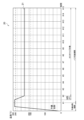
- FIG. 4 is a graph schematically showing an example of a heating profile.
- the horizontal axis of the graph 20 is time.
- the vertical axis of graph 20 is temperature.
- a line 21 shows the time series transition of the target temperature.
- the target temperature rapidly rises to around 300° C. after heating starts, then decreases to around 230° C. and is maintained until the end.
- power supply to the heating unit 121 is interrupted and heating is turned off.
- the timings at which puffs are performed from the first to the 15th time (hereinafter also referred to as puff timings) are displayed as #1 to #15.
- the puff timing may be set in advance.
- the time until the first puff timing is a preheating period, and 15 puff timings are set in the subsequent puffable period.
- the range from the second puff timing to the 15th puff timing is subject to customization, and changes in the target temperature at the first puff timing are restricted. This is because during the preheating period, it is desirable to rapidly raise the temperature of the heating section 121 and maintain it at a high temperature, and excessive temperature changes are not desirable.
- the temperature that can be set as the target temperature is limited to a range from a lower limit temperature of 190°C to an upper limit temperature of 290°C, and changes to temperatures exceeding the range are restricted. It's okay.
- the range of temperatures that can be set can be set as appropriate depending on the specifications of the heating section 121 and the like.
- the terminal device 200 controls the customization process.
- the customization process is a process of changing the heating profile used by the suction device 100.
- the terminal device 200 repeatedly executes the customization process until a heating profile that achieves the smoking taste desired by the user is generated. By repeating the customization process, the heating profile can be gradually brought closer to the ideal heating profile that achieves the user's desired smoking taste.
- the customization process includes generating a customization screen.
- the customization screen is a display image that displays an operation target for setting a target temperature included in the heating profile used by the suction device 100.
- the customization process includes changing the target temperature included in the heating profile in accordance with the user's operation on the operation target displayed on the generated customization screen.
- the flavor can be enhanced, and by lowering the target temperature, the flavor can be weakened.
- the user can gradually change the heating profile so as to approach the desired smoking taste while repeating operations on the operation target displayed on the customization screen.
- An example of the customization screen will be described with reference to FIG. 5.
- FIG. 5 is a diagram showing an example of a customization screen according to this embodiment.
- the customization screen 30 includes an axis 32 (32-1 to 312-15) on which points 31 (31-1 to 31-15) are movably arranged.
- Point 31 is an example of an object to be operated by the user.
- the position on the axis 32 corresponds to the value (ie, temperature) set as the target temperature. That is, the temperature corresponding to the position of point 31 is set as the target temperature.
- the user can change the target temperature included in the heating profile.
- the customization screen 30 includes a plurality of axes 32.
- Each of the multiple axes 32 corresponds to each of the multiple puff timings.
- the control unit 260 sets the target temperature at each of the plurality of puff timings based on the position of the point 31 on each of the plurality of axes 32.
- axis 32-3 corresponds to the third puff timing. Therefore, the control unit 260 sets the target temperature at the third puff timing based on the position of the point 31-3 on the axis 32-3.
- Terminal device 200 may display customization screen 30 and accept user operations during the heating session, or may display customization screen 30 and accept user operations after the heating session ends. According to this configuration, the user can customize the heating profile so that the smoking taste at each puff timing is as desired.
- the terminal device 200 changes the target temperature based on the position of the point 31 on the axis 32. More specifically, in the customization process, the terminal device 200 adds or subtracts a second value corresponding to the distance between the reference position and the position of the point 31 to or from a reference value corresponding to the reference position on the axis 32. , set as the target temperature.
- the terminal device 200 sets a value obtained by adding the second value to the first value as the target temperature.
- the terminal device 200 sets a value obtained by subtracting the second value from the first value as the target temperature.
- the first value corresponds to the target temperature before the change.
- the second value corresponds to the amount of change from the target temperature before change. That is, the terminal device 200 changes the target temperature more greatly as the position of the point 31 is farther from the reference position, and changes the target temperature smaller as the position of the point 31 is closer to the reference position. According to this configuration, the user can intuitively and easily change the target temperature.
- the point 31 can be moved on the axis 32 in units of a predetermined distance.
- the shaft 32 has seven scales, and the point 31 is located at the center scale and can be moved up and down to three scales. The user can set the target temperature by positioning the point 31 on any of the seven scales.
- the terminal device 200 sets a method for changing the target temperature in the next customization process based on the content of the target temperature change in the previous customization process.
- the method of changing the target temperature in the next customization process can be optimized according to the details of the change in the target temperature in the previous customization process. This makes it possible to improve usability regarding customization of the heating profile.
- the terminal device 200 determines the position on the axis 32 in the next customization process and the temperature that will be set as the target temperature when the point 31 is located at that position, based on the change in the target temperature in the previous customization process.
- Set the correspondence relationship with That is, the terminal device 200 updates the correspondence between the position on the axis 32 and the temperature corresponding to the position based on how much the target temperature was raised or lowered in the previous customization process.
- the above-mentioned correspondence relationship in the next customization process is updated in accordance with the user's intention, such as wanting to change the target temperature largely or in detail, as inferred from the content of changes in the target temperature in the previous customization process. can do. Therefore, it is possible to reach a heating profile that achieves the desired smoking taste of the user with fewer repetitions of the customization process.
- the terminal device 200 sets the first value in the next customization process based on the target temperature set in the previous customization process. More specifically, the terminal device 200 sets the target temperature set in the previous customization process as the first value in the next customization process. For example, the terminal device 200 sets the first value set for a certain puff timing as the target temperature set for the puff timing in the previous customization process. According to this configuration, in the process of repeating the customization process, it is possible to repeatedly change the target temperature based on the previously set target temperature. Note that the terminal device 200 sets an initial value as the first value in the first customization process.
- the initial position of the point 31 on the customization screen 30 is the reference position on the axis 32.
- the reference position is a position corresponding to the first value, that is, the target temperature before change. Therefore, if the position of point 31 after receiving the user operation remains at the reference position, terminal device 200 does not change the target temperature.
- the terminal device 200 changes the target temperature in accordance with the movement. According to this configuration, the user can intuitively change the heating profile by moving the point 31 from the reference position.
- the reference position may be the center of the axis 32. In the example shown in FIG. 5, the reference position is the center of the shaft 32 in the vertical direction. Then, the terminal device 200 makes the target temperature higher than before the change when the position of the point 31 is moved above the center of the axis 32, and when the position of the point 31 is moved below the center of the axis 32. If the change occurs, set the target temperature lower than before the change. According to this configuration, the user can raise or lower the target temperature by moving the point 31 up or down from the reference position.
- the terminal device 200 sets a second value per unit distance in the next customization process based on the amount of change in the target temperature in the previous customization process. Specifically, the terminal device 200 sets the amount of temperature change per scale of the axis 32 in the next customization process based on the amount of change in the target temperature in the previous customization process. The amount of temperature change per scale of the axis 32 is also referred to as resolution below.
- the terminal device 200 sets a larger resolution in the next customization process as the amount of change in the target temperature in the previous customization process is larger.
- the terminal device 200 sets the resolution in the next customization process to be smaller as the amount of change in the target temperature in the previous customization process is smaller.
- a typical flow when customizing a heating profile is to roughly change the target temperature to bring the taste closer to the ideal, and then fine-tune the taste by changing the target temperature in small steps.
- by adjusting the resolution according to the amount of change in the target temperature in the previous customization process it is possible to automatically customize the heating profile along the above typical flow.
- the terminal device 200 may set the resolution in the next customization process so that an integral multiple of the resolution in the next customization process matches the amount of change in the target temperature in the previous customization process.
- the terminal device 200 may set the resolution in the next customization process to a value obtained by dividing the amount of change in the target temperature in the previous customization process by an integer. It is desirable that the integer here remains unchanged during repeated customization processing. According to this configuration, the user can change the target temperature in the next customization process based on the amount of change in the target temperature in the previous customization process.
- the terminal device 200 may set the resolution based on the following formula.
- ⁇ T resolution.
- n is the number of repetitions of the next customization process.
- T n-1 is the target temperature set in the previous customization process.
- T n-2 is the target temperature set in the previous customization process.
- FIG. 6 is a diagram showing the correspondence between the position on the axis 32 and the temperature in the next customization process when the target temperature has been raised in the previous customization process.
- the terminal device 200 sets the target temperature T n-1 set in the previous customization process as the temperature corresponding to the scale at the center of the axis 32.
- the terminal device 200 sets T n-1 + ⁇ T as the temperature corresponding to the scale one scale above the center of the axis 32, and sets T n-1 +2 ⁇ T as the temperature corresponding to the scale two scales above, T n-1 +3 ⁇ T is set as the temperature corresponding to the third scale above.
- the terminal device 200 sets T n-1 - ⁇ T as the temperature corresponding to the scale one scale below the center of the axis 32, and sets T n-1 -2 ⁇ T as the temperature corresponding to the scale two scales below. Then, T n-1 -3 ⁇ T is set as the temperature corresponding to the third lower scale. Note that the resolution ⁇ T is calculated by the above formula (1), and since T n-1 > T n-2 , T n-1 -2 ⁇ T is equal to T n-2 .
- FIG. 7 is a diagram showing the correspondence between the position on the axis 32 and the temperature in the next customization process when the target temperature has been lowered in the previous customization process.
- the terminal device 200 sets the target temperature T n-1 set in the previous customization process as the temperature corresponding to the scale at the center of the axis 32.
- the terminal device 200 sets T n-1 + ⁇ T as the temperature corresponding to the scale one scale above the center of the axis 32, and sets T n-1 +2 ⁇ T as the temperature corresponding to the scale two scales above, T n-1 +3 ⁇ T is set as the temperature corresponding to the third scale above.
- the terminal device 200 sets T n-1 - ⁇ T as the temperature corresponding to the scale one scale below the center of the axis 32, and sets T n-1 -2 ⁇ T as the temperature corresponding to the scale two scales below. Then, T n-1 -3 ⁇ T is set as the temperature corresponding to the third lower scale. Note that the resolution ⁇ T is calculated by the above formula (1), and since T n-1 ⁇ T n-2 , T n-1 +2 ⁇ T is equal to T n-2 .
- twice the resolution ⁇ T in the next customization process matches the amount of change in the target temperature in the previous customization process. Therefore, by moving the point 31 by two scales from the center of the axis 32, the target temperature can be changed by the same amount as the previous time. Therefore, by moving the point 31 up or down by two scales from the center of the axis 32, it is possible to change the target temperature in the same way as before or cancel the previous change in the target temperature. .
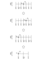
- FIG. 8 is a diagram for explaining a first specific example of updating the correspondence between the scale of the axis 32 and the temperature corresponding to one puff timing.
- This figure shows an example where the target temperature is raised in the second customization process and the third customization process.
- three scales are set on the axis 32
- seven scales are set on the axis 32. In this way, by reducing the number of scale marks it is possible to make the operation easier to understand, and by increasing the number of scale marks it is possible to make detailed customization possible.
- the terminal device 200 sets the temperature corresponding to the scale at the center of the axis 32 to 230°C, which is the initial value T0 , and sets the resolution ⁇ T to 16°C. That is, as shown in FIG. 8, the terminal device 200 sets the scale of the axis 32 to 246° C., 230° C., and 214° C. in order from the top.
- the terminal device 200 changes the target temperature from 230°C to 246°C.
- the terminal device 200 sets the temperature corresponding to the center scale of the axis 32 to 246°C, which is the target temperature T1 set in the first customization process, and ), the resolution ⁇ T is set to 8°C. That is, as shown in FIG. 8, the terminal device 200 sets the scale of the axis 32 to 270°C, 262°C, 254°C, 246°C, 238°C, 230°C, and 222°C in order from the top.
- the terminal device 200 changes the target temperature from 246°C to 270°C.
- the terminal device 200 sets the temperature corresponding to the scale at the center of the axis 32 to 270°C, which is the target temperature T2 set in the second customization process, and ), the resolution ⁇ T is set to 12°C. That is, as shown in FIG. 8, the terminal device 200 sets the scale of the axis 32 to 306°C, 294°C, 282°C, 270°C, 258°C, 246°C, and 234°C in order from the top.
- the terminal device 200 changes the target temperature from 270°C to 282°C.
- the terminal device 200 sets the temperature corresponding to the center scale of the axis 32 to 282°C, which is the target temperature T3 set in the third customization process, and ), the resolution ⁇ T is set to 6°C. That is, as shown in FIG. 8, the terminal device 200 sets the scale of the axis 32 to 302°C, 296°C, 288°C, 282°C, 276°C, 270°C, and 264°C in order from the top.
- the portion of the axis 32 that exceeds the upper limit temperature of 290° C. that can be set as the target temperature is displayed with a broken line. Then, movement of the point 31 to the broken line portion is restricted. According to this configuration, it is possible to clearly indicate to the user that setting a temperature higher than the upper limit temperature of 290° C. as the target temperature is restricted.
- FIG. 9 is a diagram for explaining a second specific example of updating the correspondence between the scale of the axis 32 corresponding to one puff timing and the temperature. This figure shows an example in which the target temperature is raised in the second customization process and lowered in the third customization process. The number of scale marks on the axis 32 from the first customization process to the fourth customization process is the same as in FIG. 8 .
- the terminal device 200 sets the temperature corresponding to the scale at the center of the axis 32 to 230°C, which is the initial value T0 , and sets the resolution ⁇ T to 16°C. That is, as shown in FIG. 9, the terminal device 200 sets the scale of the axis 32 to 246° C., 230° C., and 214° C. in order from the top.
- the terminal device 200 changes the target temperature from 230°C to 246°C.
- the terminal device 200 sets the temperature corresponding to the scale at the center of the axis 32 to 246°C, which is the target temperature T1 set in the first customization process, and uses the above formula ( Based on 1), the resolution ⁇ T is set to 8°C. That is, as shown in FIG. 9, the terminal device 200 sets the scale of the axis 32 to 270°C, 262°C, 254°C, 246°C, 238°C, 230°C, and 222°C in order from the top.
- the terminal device 200 changes the target temperature from 246°C to 262°C.
- the terminal device 200 sets the temperature corresponding to the scale at the center of the axis 32 to 262°C, which is the target temperature T2 set in the second customization process, and ), the resolution ⁇ T is set to 8°C. That is, as shown in FIG. 9, the terminal device 200 sets the scale of the axis 32 to 286°C, 278°C, 270°C, 262°C, 254°C, 246°C, and 238°C in order from the top. In the third customization process, the user moves the point 31 from the center of the axis 32 to one scale below. Therefore, the terminal device 200 changes the target temperature from 262°C to 254°C.
- the terminal device 200 sets the temperature corresponding to the center scale of the axis 32 to 254°C, which is the target temperature T3 set in the third customization process, and ), the resolution ⁇ T is set to 4°C. That is, as shown in FIG. 9, the terminal device 200 sets the scale of the axis 32 to 266°C, 262°C, 258°C, 254°C, 250°C, 246°C, and 242°C in order from the top.
- FIG. 10 is a diagram for explaining a third specific example of updating the correspondence between the scale of the axis 32 and the temperature corresponding to one puff timing. This figure shows an example where the target temperature is lowered in the second customization process and the third customization process. The number of scale marks on the axis 32 from the first customization process to the fourth customization process is the same as in FIG. 8 .
- the terminal device 200 sets the temperature corresponding to the scale at the center of the axis 32 to 230°C, which is the initial value T0 , and sets the resolution ⁇ T to 16°C. That is, as shown in FIG. 10, the terminal device 200 sets the scale of the axis 32 to 246° C., 230° C., and 214° C. in order from the top.
- the terminal device 200 changes the target temperature from 230°C to 246°C.
- the terminal device 200 sets the temperature corresponding to the center scale of the axis 32 to 246°C, which is the target temperature T1 set in the first customization process, and ), the resolution ⁇ T is set to 8°C. That is, as shown in FIG. 10, the terminal device 200 sets the scale of the axis 32 to 270°C, 262°C, 254°C, 246°C, 238°C, 230°C, and 222°C in order from the top.
- the user moves the point 31 to a scale three positions below the center of the axis 32. Therefore, the terminal device 200 changes the target temperature from 246°C to 222°C.
- the terminal device 200 sets the temperature corresponding to the scale at the center of the axis 32 to 222°C, which is the target temperature T2 set in the second customization process, and ), the resolution ⁇ T is set to 12°C. That is, as shown in FIG. 10, the terminal device 200 sets the scale of the axis 32 to 258° C., 246° C., 234° C., 222° C., 210° C., 198° C., and 186° C. in order from the top. In the third customization process, the user moves the point 31 from the center of the axis 32 to two scale marks below. Therefore, the terminal device 200 changes the target temperature from 222°C to 198°C.
- the terminal device 200 sets the temperature corresponding to the center scale of the axis 32 to 198°C, which is the target temperature T3 set in the third customization process, and ), the resolution ⁇ T is set to 12°C. That is, as shown in FIG. 10, the terminal device 200 sets the scale of the axis 32 to 234°C, 222°C, 210°C, 198°C, 186°C, 174°C, and 162°C in order from the top.
- the portion of the axis 32 that is below the lower limit temperature of 190° C. that can be set as the target temperature is displayed with a broken line. Then, movement of the point 31 to the broken line portion is restricted. According to this configuration, it becomes possible to clearly indicate to the user that setting a temperature below the lower limit temperature of 190° C. as the target temperature is restricted.
- FIG. 11 is a diagram for explaining a fourth specific example of updating the correspondence between the scale of the axis 32 and the temperature corresponding to one puff timing. This figure shows an example in which the target temperature is lowered in the second customization process and raised in the third customization process. The number of scale marks on the axis 32 from the first customization process to the fourth customization process is the same as in FIG. 8 .
- the terminal device 200 sets the temperature corresponding to the scale at the center of the axis 32 to 230°C, which is the initial value T0 , and sets the resolution ⁇ T to 16°C. That is, as shown in FIG. 11, the terminal device 200 sets the scale of the axis 32 to 246° C., 230° C., and 214° C. in order from the top.
- the terminal device 200 changes the target temperature from 230°C to 246°C.
- the terminal device 200 sets the temperature corresponding to the center scale of the axis 32 to 246°C, which is the target temperature T1 set in the first customization process, and ), the resolution ⁇ T is set to 8°C. That is, as shown in FIG. 11, the terminal device 200 sets the scale of the axis 32 to 270°C, 262°C, 254°C, 246°C, 238°C, 230°C, and 222°C from the top.
- the terminal device 200 changes the target temperature from 246°C to 238°C.
- the terminal device 200 sets the temperature corresponding to the center scale of the axis 32 to 238°C, which is the target temperature T2 set in the second customization process, and ), the resolution ⁇ T is set to 4°C. That is, as shown in FIG. 11, the terminal device 200 sets the scale of the axis 32 to 250°C, 246°C, 242°C, 238°C, 234°C, 230°C, and 226°C in order from the top.
- the terminal device 200 changes the target temperature from 238°C to 242°C.
- the terminal device 200 sets the temperature corresponding to the center scale of the axis 32 to 242°C, which is the target temperature T3 set in the third customization process, and ), the resolution ⁇ T is set to 2°C. That is, as shown in FIG. 11, the terminal device 200 sets the scale of the axis 32 to 248° C., 246° C., 244° C., 242° C., 240° C., 238° C., and 236° C. in order from the top.
- the temperature and resolution ⁇ T corresponding to each scale of the axis 32 may be displayed or hidden on the customization screen 30.
- the temperature and resolution ⁇ T corresponding to each scale of the axis 32 at each puff timing are not displayed.
- one point 31 is displayed on one axis 32 on the customization screen 30, the present invention is not limited to such an example.
- one axis 32 in addition to the point 31 that accepts user operations, there is also a point corresponding to the target temperature T n-1 set in the previous customization process, and furthermore, a point corresponding to the target temperature T n-1 set in the previous customization process.
- a point corresponding to n-2 may be displayed. In that case, the user can change the target temperature while keeping track of the change history.
- FIG. 12 is a flowchart illustrating an example of the flow of processing executed in the terminal device 200 according to the present embodiment.
- the control unit 260 detects the start of heating based on the heating profile (step S102). For example, when suction device 100 starts heating based on the heating profile, it may transmit information indicating that heating has started to terminal device 200. Based on the reception of such information, the control unit 260 can detect the start of heating based on the heating profile.
- the control unit 260 sets the temperature and resolution corresponding to the scale at the center of the axis 32, depending on the change in the target temperature in the previous customization process (step S104). At this time, the control unit 260 sets the target temperature set in the previous customization process to the temperature corresponding to the scale at the center of the axis 32. Then, the control unit 260 sets the resolution based on the amount of change in the target temperature in the previous customization process. For each puff timing, the temperature and/or resolution corresponding to the center scale of axis 32 may be different.
- control unit 260 displays the customization screen 30 and accepts a user operation to move the point 31 on the axis 32 corresponding to each puff timing (step S106).
- the control unit 260 causes the output unit 220 to display the customization screen 30 during the heating session, prompting the user to puff each time the puff timing arrives, and then displaying a screen prompting the user to move the point 31 according to the smoking taste. may be controlled.
- the control unit 260 changes the target temperature at each puff timing based on the position of the point 31 on the axis 32 corresponding to each puff timing (step S108).
- the control unit 260 adds a temperature obtained by multiplying the number of scales moved by the resolution to the target temperature set in the previous customization process. This temperature is set as the target temperature.
- the control unit 260 controls the temperature by multiplying the number of scales moved by the resolution from the target temperature set in the previous customization process. The temperature obtained by subtracting is set as the target temperature.
- the control unit 260 continues to set the target temperature set in the previous customization process as the target temperature.
- control unit 260 controls the communication unit 240 to transmit the changed heating profile to the suction device 100 (step S110). Thereby, the suction device 100 can perform heating based on the changed heating profile from next time onwards.
- the processing related to steps S102 to S110 described above corresponds to the customization processing.
- the control unit 260 determines whether the termination condition is satisfied (step S112).
- An example of the termination condition is that the user has instructed to terminate the customization process.
- Another example of a termination condition is that point 31 was not moved from the center scale of axis 32 for all puff timings. According to this process, the customization process is repeated until the change in target temperature is converged, and it becomes possible for the user to generate a heating profile that achieves the desired smoking taste.
- the terminal device 200 may change the time until the first puff timing. Specifically, when the position of the point 31-1 on the axis 32-1 corresponding to the first puff timing is raised, the terminal device 200 extends the time until the first puff timing. Good too. In this case, similar to the case of increasing the target temperature, it is possible to enhance the taste. On the other hand, if the position of the point 31-1 on the axis 32-1 corresponding to the first puff timing is lowered, the terminal device 200 may shorten the time until the first puff timing is reached. In this case, similar to the case of lowering the target temperature, it is possible to weaken the smoking taste.
- the target temperature at the second puff timing is preferably used as the temperature at which heating is turned from heating OFF to heating ON (hereinafter also referred to as heating restart temperature).
- heating restart temperature the temperature at which heating is turned from heating OFF to heating ON
- FIG. 13 is a diagram for explaining the target temperature at the second puff timing. This figure shows a case where the target temperature at the second puff timing is changed from 230°C to 246°C.
- Graph 40A shows the heating profile before change.
- the line 41A shows the time series transition of the target temperature.
- Graph 40B shows a heating profile when the target temperature is changed to 246°C and the heating restart temperature remains unchanged at 230°C.
- a line 41B shows the time series transition of the target temperature.
- Graph 40C shows a heating profile when the target temperature and heating restart temperature are changed to 246°C.
- a line 41C indicates a time series transition of the target temperature.
- the heating restart temperature remains at 230°C
- the temperature of the heating section 121 once drops to 230°C and then rises to 246°C, which has the effect of improving the smoking taste at the second puff timing. is thin.
- the heating restart temperature is changed to 246°C
- the temperature of the heating section 121 is maintained at 246°C as the lower limit, so the smoking taste at the second puff timing can be greatly improved. It becomes possible.
- the target temperature set in the previous customization process is set as the temperature corresponding to the scale at the center of the axis 32, but the present invention is not limited to such an example.
- the terminal device 200 may set a value different from the target temperature set in the previous customization process as the first value in the next customization process. For example, the terminal device 200 may set the first value for a certain puff timing as the average value of the target temperatures set for the puff timing and the puff timings before and after the puff timing in the previous customization process.
- temperatures that can be set as the target temperature are set as discrete values.
- the temperature that can be set as the target temperature may be a continuous value. That is, the point 31 may be movable between the scales on the axis 32 as well.
- the terminal device 200 may display a portion of the axis 32 that corresponds to a temperature that can be set as a target temperature in a different display manner than a portion of the axis 32 that corresponds to a temperature that cannot be set. All you have to do is do it.
- the difference in these display modes is not limited to the difference between solid lines and broken lines.
- the terminal device 200 may have different colors, thicknesses, shadings, etc.
- the heating section 121 is configured as a heating resistor and generates heat by electric resistance, but the present invention is not limited to such an example.
- the heating unit 121 may include an electromagnetic induction source such as a coil that generates a magnetic field, and a susceptor that generates heat by induction heating, and the stick-shaped base material 150 may be heated by the susceptor.
- the control unit 116 applies an alternating current to the electromagnetic induction source to generate an alternating magnetic field, and causes the alternating magnetic field to enter the susceptor, thereby causing the susceptor to generate heat.
- the temperature at which the aerosol source is heated which is controlled based on the heating profile, will be the temperature of the susceptor.
- the temperature of the susceptor can be estimated based on the electrical resistance value of the electromagnetic induction source.
- the parameter related to the temperature at which the aerosol source is heated which is defined in the heating profile, is the target temperature of the heating section 121, but the present invention is not limited to such an example.
- Parameters related to the temperature at which the aerosol source is heated include the electrical resistance value of the heating section 121 in addition to the temperature itself of the heating section 121 described in the above embodiment.
- the suction device 100 includes an electromagnetic induction source instead of the heating unit 121
- the parameters related to the temperature for heating the aerosol source specified in the heating profile include the temperature of the susceptor, the electrical resistance value of the electromagnetic induction source, etc. Target values can be mentioned.
- the suction device 100 may be configured as a so-called liquid atomization type aerosol generation device that generates aerosol by heating and atomizing a liquid aerosol source.
- the present invention is also applicable to liquid atomization type aerosol generation devices.
- Each device described in this specification may be realized as a single device, or a part or all of it may be realized as a separate device.
- the control unit 260 of the terminal device 200 may be included in a device such as a server connected to the terminal device 200 via a network or the like. That is, customization of the heating profile may be performed by a server on the cloud based on a user operation input into the terminal device 200.
- each device described in this specification may be realized using software, hardware, or a combination of software and hardware.
- a program constituting the software is stored in advance, for example, in a recording medium (specifically, a computer-readable non-temporary storage medium) provided inside or outside each device.
- each program is read into the RAM when executed by a computer that controls each device described in this specification, and is executed by a processing circuit such as a CPU.
- the recording medium is, for example, a magnetic disk, an optical disk, a magneto-optical disk, a flash memory, or the like.
- the above computer program may be distributed, for example, via a network, without using a recording medium.
- the above-mentioned computer may be an application-specific integrated circuit such as an ASIC, a general-purpose processor that executes functions by loading a software program, or a computer on a server used for cloud computing. Furthermore, a series of processes performed by each device described in this specification may be distributed and processed by multiple computers.
- the parameters included in the control information are used by a suction device that generates an aerosol by heating an aerosol source included in a base material based on control information that defines parameters regarding the temperature at which the aerosol source is heated.
- Information processing device is used by a suction device that generates an aerosol by heating an aerosol source included in a base material based on control information that defines parameters regarding the temperature at which the aerosol source is heated.
- the display image includes an axis on which the operation target is movably arranged
- the control unit includes: changing the parameters based on the position of the operation target on the axis in the customization process; Based on the changes to the parameters in the previous customization process, determine the correspondence between the position on the axis in the next customization process and the value set as the parameter when the operation target is located at the position. set, The information processing device according to (1) above.
- the control unit includes: In the customization process, a value obtained by adding or subtracting a second value corresponding to a difference between the reference position and the operation target position to a first value corresponding to the reference position on the axis is used as the parameter.
- the control unit sets the parameter set in the previous customization process to the first value in the next customization process;
- the control unit includes: In the customization process, a value obtained by adding or subtracting a second value corresponding to a distance between the reference position and the operation target position to a first value corresponding to the reference position on the axis is used as the parameter.
- Set setting the second value per unit distance in the next customization process based on a change amount of the parameter in the previous customization process; The information processing device according to any one of (2) to (4) above.
- the control unit sets the second value per unit distance in the next customization process to be larger as the amount of change in the parameter in the previous customization process is larger, and the control unit sets the second value per unit distance in the next customization process to a larger value, The smaller the amount, the smaller the second value per unit distance in the next customization process.
- the information processing device according to (5) above.
- the control unit adjusts the unit in the next customization process so that an integral multiple of the second value per unit distance in the next customization process matches the change amount of the parameter in the previous customization process. setting the second value per distance;
- the initial position of the operation target in the display image is the reference position on the axis; The information processing device according to any one of (3) to (7) above.
- the reference position is the center of the axis;
- the information processing device according to (8) above.
- the displayed image includes a plurality of axes, each of the plurality of axes corresponding to each of a plurality of puff timings,
- the control unit sets the parameters at each of the plurality of puff timings based on the position of the operation target on each of the plurality of axes.
- the information processing device according to any one of (2) to (9) above.
- the control unit causes a display mode of a portion of the axis corresponding to a value that can be set as the parameter to be different from a display mode of a portion of the axis that corresponds to a value that cannot be set.
- the information processing device according to any one of (2) to (10) above.
- the parameters included in the control information are used by a suction device that generates an aerosol by heating an aerosol source included in a base material based on control information that defines parameters regarding the temperature at which the aerosol source is heated.
- Controlling the customization process includes setting a method for changing the parameter in the next customization process based on the content of the change in the parameter in the previous customization process when repeatedly executing the customization process. include, Information processing method.
- the parameters included in the control information are used by a suction device that generates an aerosol by heating an aerosol source included in a base material based on control information that defines parameters regarding the temperature at which the aerosol source is heated.
Abstract
[Problem] To provide a customization mechanism with which it is possible to easily realize a flavor desired by a user. [Solution] An information processing device used by an inhalation device for heating an aerosol source contained in a substrate on the basis of control information stipulating a parameter relating to a temperature to which the aerosol source is to be heated to generate an aerosol, the information processing device comprising a control unit for controlling a customization process including generating a display image displaying an operation subject for setting the parameter included in the control information, and changing the parameter included in the control information in accordance with a user operation on the operation subject displayed in the generated display image. When repeatedly executing the customization process, the control unit sets a method for changing the parameter in a subsequent customization process on the basis of change content for the parameter in the previous customization process.
Description
本発明は、情報処理装置、情報処理方法、及びプログラムに関する。
The present invention relates to an information processing device, an information processing method, and a program.
電子タバコ及びネブライザ等の、ユーザに吸引される物質を生成する吸引装置が広く普及している。例えば、吸引装置は、エアロゾルを生成するためのエアロゾル源、及び生成されたエアロゾルに香味成分を付与するための香味源等を含む基材を用いて、香味成分が付与されたエアロゾルを生成する。ユーザは、吸引装置により生成された、香味成分が付与されたエアロゾルを吸引することで、香味を味わうことができる。ユーザがエアロゾルを吸引する動作を、以下ではパフ又はパフ動作とも称する。
Inhalation devices, such as electronic cigarettes and nebulizers, that produce substances that are inhaled by a user are widespread. For example, a suction device generates an aerosol to which a flavor component has been added using a base material that includes an aerosol source for generating an aerosol, a flavor source for imparting a flavor component to the generated aerosol, and the like. The user can taste the flavor by inhaling the aerosol to which the flavor component is added, which is generated by the suction device. The action of the user inhaling an aerosol will also be referred to below as a puff or a puff action.
パフした際に味わう香味(以下、喫味とも称する)に対する好みは、ユーザごとに異なる。そのため、喫味に直接的な影響を与えるエアロゾル源を加熱する温度が、ユーザによりカスタマイズ可能であることが好ましい。下記特許文献1には、エアロゾル源を加熱する温度をユーザがカスタマイズする技術が開示されている。
Preferences for the flavor experienced when puffing (hereinafter also referred to as smoking flavor) differ from user to user. Therefore, it is preferable that the temperature at which the aerosol source is heated, which directly affects the taste, can be customized by the user. Patent Document 1 listed below discloses a technique in which a user customizes the temperature at which an aerosol source is heated.
しかし、上記特許文献1に開示された技術では、ユーザが思い通りのカスタマイズを行うことが困難な場合があった。
However, with the technology disclosed in Patent Document 1, it may be difficult for the user to customize the device as desired.
そこで、本発明は、上記問題に鑑みてなされたものであり、本発明の目的とするところは、ユーザが思い通りの喫味を容易に実現可能なカスタマイズの仕組みを提供することにある。
Therefore, the present invention has been made in view of the above problems, and an object of the present invention is to provide a customization mechanism that allows the user to easily achieve the desired smoking taste.
上記課題を解決するために、本発明のある観点によれば、基材に含まれるエアロゾル源を、前記エアロゾル源を加熱する温度に関するパラメータを規定する制御情報に基づいて加熱することでエアロゾルを生成する吸引装置により使用される、前記制御情報に含まれる前記パラメータを設定するための操作対象を表示する表示画像を生成することと、生成した前記表示画像に表示された前記操作対象に対するユーザ操作に応じて、前記制御情報に含まれる前記パラメータを変更することと、を含むカスタマイズ処理を制御する制御部、を備え、前記制御部は、前記カスタマイズ処理を繰り返し実行する際に、前回の前記カスタマイズ処理における前記パラメータの変更内容に基づいて、次回の前記カスタマイズ処理における前記パラメータの変更方法を設定する、情報処理装置が提供される。
In order to solve the above problems, according to one aspect of the present invention, an aerosol is generated by heating an aerosol source included in a base material based on control information that defines parameters regarding the temperature at which the aerosol source is heated. generating a display image displaying an operation target for setting the parameter included in the control information used by the suction device; and a user operation on the operation target displayed in the generated display image. a control unit that controls a customization process including changing the parameters included in the control information according to the control information; An information processing apparatus is provided, which sets a method for changing the parameters in the next customization process based on the content of the changes in the parameters.
前記表示画像は、前記操作対象が移動可能に配置された軸を含み、前記制御部は、前記カスタマイズ処理において前記軸上の前記操作対象の位置に基づいて前記パラメータを変更し、前回の前記カスタマイズ処理における前記パラメータの変更内容に基づいて、次回の前記カスタマイズ処理における前記軸上の位置と当該位置に前記操作対象が位置する場合に前記パラメータとして設定される値との対応関係を設定してもよい。
The display image includes an axis on which the operation target is movably arranged, and the control unit changes the parameters based on the position of the operation target on the axis in the customization process, and changes the parameters based on the position of the operation target on the axis in the customization process, Based on the changes to the parameters in the process, a correspondence relationship between the position on the axis in the next customization process and the value set as the parameter when the operation target is located at the position may be set. good.
前記制御部は、前記カスタマイズ処理において、前記軸上の基準位置に対応する第1の値に、前記基準位置と前記操作対象の位置との差分に対応する第2の値を加算又は減算した値を、前記パラメータとして設定し、前回の前記カスタマイズ処理において設定された前記パラメータに基づいて、次回の前記カスタマイズ処理における前記第1の値を設定してもよい。
In the customization process, the control unit adds or subtracts a second value corresponding to a difference between the reference position and the operation target position to a first value corresponding to the reference position on the axis. may be set as the parameter, and the first value in the next customization process may be set based on the parameter set in the previous customization process.
前記制御部は、前回の前記カスタマイズ処理において設定された前記パラメータを、次回の前記カスタマイズ処理における前記第1の値に設定してもよい。
The control unit may set the parameter set in the previous customization process to the first value in the next customization process.
前記制御部は、前記カスタマイズ処理において、前記軸上の基準位置に対応する第1の値に、前記基準位置と前記操作対象の位置との距離に対応する第2の値を加算又は減算した値を、前記パラメータとして設定し、前回の前記カスタマイズ処理における前記パラメータの変更量に基づいて、次回の前記カスタマイズ処理における単位距離当たりの前記第2の値を設定してもよい。
In the customization process, the control unit adds or subtracts a second value corresponding to a distance between the reference position and the operation target position to a first value corresponding to the reference position on the axis. may be set as the parameter, and the second value per unit distance in the next customization process may be set based on the amount of change in the parameter in the previous customization process.
前記制御部は、前回の前記カスタマイズ処理における前記パラメータの変更量が大きいほど次回の前記カスタマイズ処理における前記単位距離当たりの前記第2の値を大きく設定し、前回の前記カスタマイズ処理における前記パラメータの変更量が小さいほど次回の前記カスタマイズ処理における前記単位距離当たりの前記第2の値を小さく設定してもよい。
The control unit sets the second value per unit distance in the next customization process to be larger as the amount of change in the parameter in the previous customization process is larger, and the control unit sets the second value per unit distance in the next customization process to a larger value, The smaller the amount, the smaller the second value per unit distance may be set in the next customization process.
前記制御部は、次回の前記カスタマイズ処理における前記単位距離当たりの前記第2の値の整数倍が、前回の前記カスタマイズ処理における前記パラメータの変更量に一致するよう、次回の前記カスタマイズ処理における前記単位距離当たりの前記第2の値を設定してもよい。
The control unit adjusts the unit in the next customization process so that an integral multiple of the second value per unit distance in the next customization process matches the change amount of the parameter in the previous customization process. The second value per distance may be set.
前記表示画像における前記操作対象の初期位置は、前記軸上の前記基準位置であってもよい。
The initial position of the operation target in the display image may be the reference position on the axis.
前記基準位置は、前記軸の中心であってもよい。
The reference position may be the center of the axis.
前記表示画像は、複数の前記軸を含み、複数の前記軸の各々は複数のパフタイミングの各々に対応し、前記制御部は、複数の前記軸の各々における前記操作対象の位置に基づいて、複数の前記パフタイミングの各々における前記パラメータを設定してもよい。
The display image includes a plurality of the axes, each of the plurality of axes corresponds to each of the plurality of puff timings, and the control unit, based on the position of the operation target on each of the plurality of axes, The parameters may be set for each of the plurality of puff timings.
前記制御部は、前記表示画像において、前記軸のうち前記パラメータとして設定可能な値に対応する部分の表示態様と前記軸のうち設定不可能な値に対応する部分の表示態様とを異ならせてもよい。
The control unit is configured to cause, in the display image, a display mode of a portion of the axis that corresponds to a value that can be set as the parameter to be different from a display mode of a portion of the axis that corresponds to a value that cannot be set. Good too.
また、上記課題を解決するために、本発明の別の観点によれば、基材に含まれるエアロゾル源を、前記エアロゾル源を加熱する温度に関するパラメータを規定する制御情報に基づいて加熱することでエアロゾルを生成する吸引装置により使用される、前記制御情報に含まれる前記パラメータを設定するための操作対象を表示する表示画像を生成することと、生成した前記表示画像に表示された前記操作対象に対するユーザ操作に応じて、前記制御情報に含まれる前記パラメータを変更することと、を含むカスタマイズ処理を制御することを含み、前記カスタマイズ処理を制御することは、前記カスタマイズ処理を繰り返し実行する際に、前回の前記カスタマイズ処理における前記パラメータの変更内容に基づいて、次回の前記カスタマイズ処理における前記パラメータの変更方法を設定することを含む、情報処理方法が提供される。
Moreover, in order to solve the above-mentioned problem, according to another aspect of the present invention, an aerosol source included in a base material is heated based on control information that defines a parameter regarding the temperature at which the aerosol source is heated. generating a display image that displays an operation target for setting the parameter included in the control information used by a suction device that generates an aerosol; and controlling a customization process including changing the parameters included in the control information in response to a user operation, and controlling the customization process includes: when repeatedly executing the customization process; An information processing method is provided that includes setting a method for changing the parameters in the next customization process based on changes to the parameters in the previous customization process.
また、上記課題を解決するために、本発明の別の観点によれば、コンピュータを、基材に含まれるエアロゾル源を、前記エアロゾル源を加熱する温度に関するパラメータを規定する制御情報に基づいて加熱することでエアロゾルを生成する吸引装置により使用される、前記制御情報に含まれる前記パラメータを設定するための操作対象を表示する表示画像を生成することと、生成した前記表示画像に表示された前記操作対象に対するユーザ操作に応じて、前記制御情報に含まれる前記パラメータを変更することと、を含むカスタマイズ処理を制御する制御部、として機能させ、前記制御部は、前記カスタマイズ処理を繰り返し実行する際に、前回の前記カスタマイズ処理における前記パラメータの変更内容に基づいて、次回の前記カスタマイズ処理における前記パラメータの変更方法を設定する、プログラムが提供される。
Further, in order to solve the above problems, according to another aspect of the present invention, the computer heats the aerosol source included in the base material based on control information that defines parameters regarding the temperature at which the aerosol source is heated. generating a display image displaying an operation target for setting the parameter included in the control information used by a suction device that generates an aerosol; a control unit that controls a customization process including changing the parameters included in the control information in accordance with a user operation on an operation target; Further, a program is provided that sets a method for changing the parameters in the next customization process based on the changes to the parameters in the previous customization process.
以上説明したように本発明によれば、ユーザが思い通りの喫味を容易に実現可能なカスタマイズの仕組みが提供される。
As explained above, according to the present invention, a customization mechanism is provided that allows the user to easily achieve the desired smoking taste.
以下に添付図面を参照しながら、本発明の好適な実施の形態について詳細に説明する。なお、本明細書及び図面において、実質的に同一の機能構成を有する構成要素については、同一の符号を付することにより重複説明を省略する。
Preferred embodiments of the present invention will be described in detail below with reference to the accompanying drawings. Note that, in this specification and the drawings, components having substantially the same functional configurations are designated by the same reference numerals and redundant explanation will be omitted.
<1.構成例>
(1)システムの構成例
図1は、一実施形態に係るシステム1の構成例を説明するための図である。図1に示すように、システム1は、吸引装置100、及び端末装置200を含む。 <1. Configuration example>
(1) System configuration example FIG. 1 is a diagram for explaining a configuration example of asystem 1 according to an embodiment. As shown in FIG. 1, the system 1 includes a suction device 100 and a terminal device 200.
(1)システムの構成例
図1は、一実施形態に係るシステム1の構成例を説明するための図である。図1に示すように、システム1は、吸引装置100、及び端末装置200を含む。 <1. Configuration example>
(1) System configuration example FIG. 1 is a diagram for explaining a configuration example of a
吸引装置100は、ユーザにより吸引される物質を生成する装置である。以下では、吸引装置100により生成される物質は、エアロゾルであるものとして説明する。他に、吸引装置により生成される物質は、気体であってもよい。吸引装置100は、スティック型基材150を使用して、エアロゾルを生成する。スティック型基材150は、エアロゾル源を含有する基材の一例である。吸引装置100は、基材に含まれるエアロゾル源を加熱してエアロゾルを生成するエアロゾル生成装置の一例である。
The suction device 100 is a device that generates a substance to be suctioned by a user. In the following, the substance generated by the suction device 100 will be described as an aerosol. Alternatively, the substance produced by the suction device may be a gas. The suction device 100 uses a stick-type base material 150 to generate an aerosol. Stick type substrate 150 is an example of a substrate containing an aerosol source. The suction device 100 is an example of an aerosol generation device that generates aerosol by heating an aerosol source contained in a base material.
端末装置200は、吸引装置100に関する各種情報処理を行う情報処理装置である。端末装置200は、吸引装置100のユーザにより使用される。端末装置200は、スマートフォン、タブレット端末、ウェアラブルデバイス、又はPC(Personal Computer)等の任意の装置であってよい。若しくは、端末装置200は、吸引装置100を充電する充電器であってもよい。
The terminal device 200 is an information processing device that performs various information processing regarding the suction device 100. The terminal device 200 is used by the user of the suction device 100. The terminal device 200 may be any device such as a smartphone, a tablet terminal, a wearable device, or a PC (Personal Computer). Alternatively, the terminal device 200 may be a charger that charges the suction device 100.
端末装置200は、吸引装置100の設定を変更するために使用される。例えば、端末装置200は、吸引装置100の設定を変更するためのユーザ操作を受け付け、吸引装置100の設定を変更する。
The terminal device 200 is used to change the settings of the suction device 100. For example, the terminal device 200 receives a user operation for changing the settings of the suction device 100, and changes the settings of the suction device 100.
(2)吸引装置の構成例
図2は、本実施形態に係る吸引装置の構成例を模式的に示す模式図である。図2に示すように、吸引装置100は、電源部111、センサ部112、通知部113、記憶部114、通信部115、制御部116、加熱部121、保持部140、及び断熱部144を含む。 (2) Configuration example of suction device FIG. 2 is a schematic diagram schematically showing a configuration example of the suction device according to the present embodiment. As shown in FIG. 2, thesuction device 100 includes a power supply section 111, a sensor section 112, a notification section 113, a storage section 114, a communication section 115, a control section 116, a heating section 121, a holding section 140, and a heat insulation section 144. .
図2は、本実施形態に係る吸引装置の構成例を模式的に示す模式図である。図2に示すように、吸引装置100は、電源部111、センサ部112、通知部113、記憶部114、通信部115、制御部116、加熱部121、保持部140、及び断熱部144を含む。 (2) Configuration example of suction device FIG. 2 is a schematic diagram schematically showing a configuration example of the suction device according to the present embodiment. As shown in FIG. 2, the
電源部111は、電力を蓄積する。そして、電源部111は、制御部116による制御に基づいて、吸引装置100の各構成要素に電力を供給する。電源部111は、例えば、リチウムイオン二次電池等の充電式バッテリにより構成され得る。
The power supply unit 111 stores power. Then, the power supply unit 111 supplies power to each component of the suction device 100 based on control by the control unit 116. The power supply unit 111 may be configured with a rechargeable battery such as a lithium ion secondary battery, for example.
センサ部112は、吸引装置100に関する各種情報を取得する。一例として、センサ部112は、コンデンサマイクロホン等の圧力センサ、流量センサ又は温度センサ等により構成され、ユーザによる吸引に伴う値を取得する。他の一例として、センサ部112は、ボタン又はスイッチ等の、ユーザからの情報の入力を受け付ける入力装置により構成される。
The sensor unit 112 acquires various information regarding the suction device 100. As an example, the sensor unit 112 includes a pressure sensor such as a condenser microphone, a flow rate sensor, a temperature sensor, etc., and acquires a value associated with suction by the user. As another example, the sensor unit 112 is configured with an input device such as a button or a switch that receives information input from the user.
通知部113は、情報をユーザに通知する。通知部113は、例えば、発光する発光装置、画像を表示する表示装置、音を出力する音出力装置、又は振動する振動装置等により構成される。
The notification unit 113 notifies the user of information. The notification unit 113 includes, for example, a light emitting device that emits light, a display device that displays an image, a sound output device that outputs sound, a vibration device that vibrates, or the like.
記憶部114は、吸引装置100の動作のための各種情報を記憶する。記憶部114は、例えば、フラッシュメモリ等の不揮発性の記憶媒体により構成される。
The storage unit 114 stores various information for the operation of the suction device 100. The storage unit 114 is configured by, for example, a nonvolatile storage medium such as a flash memory.
通信部115は、有線又は無線の任意の通信規格に準拠した通信を行うことが可能な通信インタフェースである。かかる通信規格としては、例えば、Wi-Fi(登録商標)、Bluetooth(登録商標)、NFC(Near Field Communication)、又はLPWA(Low Power Wide Area)を用いる規格等が採用され得る。
The communication unit 115 is a communication interface that can perform communication compliant with any wired or wireless communication standard. As such a communication standard, for example, a standard using Wi-Fi (registered trademark), Bluetooth (registered trademark), NFC (Near Field Communication), or LPWA (Low Power Wide Area) may be adopted.
制御部116は、演算処理装置及び制御装置として機能し、各種プログラムに従って吸引装置100内の動作全般を制御する。制御部116は、例えばCPU(Central Processing Unit)、又はマイクロプロセッサ等の電子回路によって実現される。
The control unit 116 functions as an arithmetic processing device and a control device, and controls overall operations within the suction device 100 according to various programs. The control unit 116 is realized by, for example, an electronic circuit such as a CPU (Central Processing Unit) or a microprocessor.
保持部140は、内部空間141を有し、内部空間141にスティック型基材150の一部を収容しながらスティック型基材150を保持する。保持部140は、内部空間141を外部に連通する開口142を有し、開口142から内部空間141に挿入されたスティック型基材150を保持する。例えば、保持部140は、開口142及び底部143を底面とする筒状体であり、柱状の内部空間141を画定する。保持部140には、内部空間141に空気を供給する空気流路が接続される。空気流路への空気の入口である空気流入孔は、例えば、吸引装置100の側面に配置される。空気流路から内部空間141への空気の出口である空気流出孔は、例えば、底部143に配置される。
The holding part 140 has an internal space 141 and holds the stick-type base material 150 while accommodating a part of the stick-type base material 150 in the internal space 141. The holding part 140 has an opening 142 that communicates the internal space 141 with the outside, and holds the stick-shaped base material 150 inserted into the internal space 141 through the opening 142. For example, the holding part 140 is a cylindrical body having an opening 142 and a bottom part 143 as the bottom surface, and defines a columnar internal space 141. An air flow path that supplies air to the internal space 141 is connected to the holding portion 140 . An air inflow hole, which is an inlet of air to the air flow path, is arranged on a side surface of the suction device 100, for example. An air outlet hole, which is an outlet for air from the air flow path to the internal space 141, is arranged at the bottom 143, for example.
スティック型基材150は、基材部151、及び吸口部152を含む。基材部151は、エアロゾル源を含む。エアロゾル源は、例えば、グリセリン及びプロピレングリコール等の多価アルコール、並びに水等の液体である。エアロゾル源は、たばこ由来又は非たばこ由来の香味成分を含んでいてもよい。吸引装置100がネブライザ等の医療用吸入器である場合、エアロゾル源は、薬剤を含んでもよい。なお、本構成例において、エアロゾル源は液体に限られるものではなく、固体であってもよい。スティック型基材150が保持部140に保持された状態において、基材部151の少なくとも一部は内部空間141に収容され、吸口部152の少なくとも一部は開口142から突出する。そして、開口142から突出した吸口部152をユーザが咥えて吸引すると、図示しない空気流路を経由して内部空間141に空気が流入し、基材部151から発生するエアロゾルと共にユーザの口内に到達する。
The stick-type base material 150 includes a base portion 151 and a mouthpiece portion 152. Base portion 151 includes an aerosol source. Aerosol sources are, for example, polyhydric alcohols such as glycerin and propylene glycol, and liquids such as water. The aerosol source may include flavor components of tobacco or non-tobacco origin. If the suction device 100 is a medical inhaler, such as a nebulizer, the aerosol source may include a drug. Note that in this configuration example, the aerosol source is not limited to a liquid, and may be a solid. In a state where the stick-shaped base material 150 is held by the holding part 140, at least a portion of the base material part 151 is accommodated in the internal space 141, and at least a part of the mouthpiece part 152 protrudes from the opening 142. When the user holds the mouthpiece 152 protruding from the opening 142 and sucks it, air flows into the internal space 141 via an air flow path (not shown) and reaches the user's mouth together with the aerosol generated from the base member 151. do.
加熱部121は、エアロゾル源を加熱することで、エアロゾル源を霧化してエアロゾルを生成する。図2に示した例では、加熱部121は、フィルム状に構成され、保持部140の外周を覆うように配置される。そして、加熱部121が発熱すると、スティック型基材150の基材部151が外周から加熱され、エアロゾルが生成される。加熱部121は、電源部111から給電されると発熱する。一例として、ユーザが吸引を開始したこと、及び/又は所定の情報が入力されたことが、センサ部112により検出された場合に、給電されてもよい。そして、ユーザが吸引を終了したこと、及び/又は所定の情報が入力されたことが、センサ部112により検出された場合に、給電が停止されてもよい。
The heating unit 121 atomizes the aerosol source to generate aerosol by heating the aerosol source. In the example shown in FIG. 2, the heating section 121 is configured in a film shape and is arranged to cover the outer periphery of the holding section 140. When the heating part 121 generates heat, the base material part 151 of the stick-type base material 150 is heated from the outer periphery, and an aerosol is generated. The heating unit 121 generates heat when supplied with power from the power supply unit 111 . As an example, power may be supplied when the sensor unit 112 detects that the user has started suctioning and/or that predetermined information has been input. Then, when the sensor unit 112 detects that the user has finished suctioning and/or that predetermined information has been input, the power supply may be stopped.
断熱部144は、加熱部121から他の構成要素への伝熱を防止する。例えば、断熱部144は、真空断熱材、又はエアロゲル断熱材等により構成される。
The heat insulating section 144 prevents heat transfer from the heating section 121 to other components. For example, the heat insulating section 144 is made of a vacuum heat insulating material, an airgel heat insulating material, or the like.
以上、吸引装置100の構成例を説明した。もちろん吸引装置100の構成は上記に限定されず、以下に例示する多様な構成をとり得る。
The configuration example of the suction device 100 has been described above. Of course, the configuration of the suction device 100 is not limited to the above, and may take various configurations as exemplified below.
一例として、加熱部121は、ブレード状に構成され、保持部140の底部143から内部空間141に突出するように配置されてもよい。その場合、ブレード状の加熱部121は、スティック型基材150の基材部151に挿入され、スティック型基材150の基材部151を内部から加熱する。他の一例として、加熱部121は、保持部140の底部143を覆うように配置されてもよい。また、加熱部121は、保持部140の外周を覆う第1の加熱部、ブレード状の第2の加熱部、及び保持部140の底部143を覆う第3の加熱部のうち、2以上の組み合わせとして構成されてもよい。
As an example, the heating unit 121 may be configured in a blade shape and arranged to protrude from the bottom 143 of the holding unit 140 into the internal space 141. In that case, the blade-shaped heating unit 121 is inserted into the base portion 151 of the stick-type base material 150 and heats the base portion 151 of the stick-type base material 150 from inside. As another example, the heating part 121 may be arranged to cover the bottom part 143 of the holding part 140. In addition, the heating section 121 is a combination of two or more of a first heating section that covers the outer periphery of the holding section 140 , a second heating section shaped like a blade, and a third heating section that covers the bottom 143 of the holding section 140 . It may be configured as
他の一例として、保持部140は、内部空間141を形成する外殻の一部を開閉する、ヒンジ等の開閉機構を含んでいてもよい。そして、保持部140は、外殻を開閉することで、内部空間141に挿入されたスティック型基材150を挟持してもよい。その場合、加熱部121は、保持部140における当該挟持箇所に設けられ、スティック型基材150を押圧しながら加熱してもよい。
As another example, the holding part 140 may include an opening/closing mechanism such as a hinge that opens and closes a part of the outer shell that forms the internal space 141. The holding part 140 may hold the stick-shaped base material 150 inserted into the internal space 141 by opening and closing the outer shell. In that case, the heating unit 121 may be provided at the relevant clamping location in the holding unit 140 and may heat the stick-shaped base material 150 while pressing it.
また、エアロゾル源を霧化する手段は、加熱部121による加熱に限定されない。例えば、エアロゾル源を霧化する手段は、誘導加熱であってもよい。その場合、吸引装置100は、加熱部121の代わりに、磁場を発生させるコイル等の電磁誘導源を少なくとも有する。誘導加熱により発熱するサセプタは、吸引装置100に設けられていてもよいし、スティック型基材150に含まれていてもよい。
Further, the means for atomizing the aerosol source is not limited to heating by the heating unit 121. For example, the means of atomizing the aerosol source may be induction heating. In that case, the suction device 100 includes at least an electromagnetic induction source such as a coil that generates a magnetic field instead of the heating unit 121. The susceptor that generates heat by induction heating may be provided in the suction device 100 or may be included in the stick-shaped base material 150.
なお、吸引装置100は、スティック型基材150と協働することで、ユーザに吸引されるエアロゾルを生成する。そのため、吸引装置100及びスティック型基材150の組み合わせは、エアロゾル生成システムとして捉えられてもよい。
Note that the suction device 100 works together with the stick-shaped base material 150 to generate an aerosol that is suctioned by the user. Therefore, the combination of the suction device 100 and the stick-type base material 150 may be regarded as an aerosol generation system.
(3)端末装置の構成例
図3は、本実施形態に係る端末装置200の構成例を示すブロック図である。図3に示すように、端末装置200は、入力部210、出力部220、検出部230、通信部240、記憶部250、及び制御部260を含む。 (3) Configuration example of terminal device FIG. 3 is a block diagram showing a configuration example of theterminal device 200 according to the present embodiment. As shown in FIG. 3, the terminal device 200 includes an input section 210, an output section 220, a detection section 230, a communication section 240, a storage section 250, and a control section 260.
図3は、本実施形態に係る端末装置200の構成例を示すブロック図である。図3に示すように、端末装置200は、入力部210、出力部220、検出部230、通信部240、記憶部250、及び制御部260を含む。 (3) Configuration example of terminal device FIG. 3 is a block diagram showing a configuration example of the
入力部210は、各種情報の入力を受け付ける機能を有する。入力部210は、ユーザからの情報の入力を受け付ける入力装置を含んでいてもよい。入力装置としては、例えば、ボタン、キーボード、タッチパネル、及びマイク等が挙げられる。他にも、入力部210は、画像センサ等の各種センサを含んでいてもよい。
The input unit 210 has a function of accepting input of various information. Input unit 210 may include an input device that accepts information input from a user. Examples of the input device include buttons, keyboards, touch panels, and microphones. In addition, the input unit 210 may include various sensors such as an image sensor.
出力部220は、情報を出力する機能を有する。出力部220は、ユーザに対し情報を出力する出力装置を含んでいてもよい。出力装置としては、例えば、情報を表示する表示装置、発光する発光装置、振動する振動装置、及び音を出力する音出力装置等が挙げられる。表示装置の一例は、ディスプレイである。発光装置の一例は、LED(Light Emitting Diode)である。振動装置の一例は、偏心モータである。音出力装置の一例は、スピーカである。出力部220は、制御部260から入力された情報を出力することで、情報をユーザに通知する。
The output unit 220 has a function of outputting information. The output unit 220 may include an output device that outputs information to the user. Examples of the output device include a display device that displays information, a light emitting device that emits light, a vibration device that vibrates, and a sound output device that outputs sound. An example of a display device is a display. An example of a light emitting device is an LED (Light Emitting Diode). An example of a vibrating device is an eccentric motor. An example of a sound output device is a speaker. The output unit 220 notifies the user of the information by outputting the information input from the control unit 260.
検出部230は、端末装置200に関する情報を検出する機能を有する。検出部230は、端末装置200の位置情報を検出してもよい。例えば、検出部230は、GNSS(Global Navigation Satellite System)衛星からのGNSS信号(例えば、GPS(Global Positioning System)衛星からのGPS信号)を受信して装置の緯度、及び経度から成る位置情報を検出する。検出部230は、端末装置200の動きを検出してもよい。例えば、検出部230は、ジャイロセンサ及び加速度センサを含み、角速度及び加速度を検出する。
The detection unit 230 has a function of detecting information regarding the terminal device 200. The detection unit 230 may detect position information of the terminal device 200. For example, the detection unit 230 receives a GNSS signal from a GNSS (Global Navigation Satellite System) satellite (e.g., a GPS signal from a GPS (Global Positioning System) satellite) and detects position information consisting of latitude and longitude of the device. do. The detection unit 230 may detect the movement of the terminal device 200. For example, the detection unit 230 includes a gyro sensor and an acceleration sensor, and detects angular velocity and acceleration.
通信部240は、端末装置200と他の装置との間で情報の送受信を行うための、通信インタフェースである。通信部240は、有線又は無線の任意の通信規格に準拠した通信を行う。かかる通信規格としては、例えば、USB(Universal Serial Bus)、Wi-Fi(登録商標)、Bluetooth(登録商標)、NFC(Near Field Communication)、又はLPWA(Low Power Wide Area)を用いる規格等が採用され得る。
The communication unit 240 is a communication interface for transmitting and receiving information between the terminal device 200 and other devices. The communication unit 240 performs communication based on any wired or wireless communication standard. Examples of such communication standards include standards using USB (Universal Serial Bus), Wi-Fi (registered trademark), Bluetooth (registered trademark), NFC (Near Field Communication), or LPWA (Low Power Wide Area). can be done.
記憶部250は、各種情報を記憶する。記憶部250は、例えば、フラッシュメモリ等の不揮発性の記憶媒体により構成される。
The storage unit 250 stores various information. The storage unit 250 is configured by, for example, a nonvolatile storage medium such as a flash memory.
制御部260は、演算処理装置又は制御装置として機能し、各種プログラムに従って端末装置200内の動作全般を制御する。制御部260は、例えばCPU(Central Processing Unit)、又はマイクロプロセッサ等の電子回路によって実現される。他に、制御部260は、使用するプログラム及び演算パラメータ等を記憶するROM(Read Only Memory)、並びに適宜変化するパラメータ等を一時記憶するRAM(Random Access Memory)を含んでいてもよい。端末装置200は、制御部260による制御に基づいて、各種処理を実行する。入力部210により入力された情報の処理、出力部220による情報の出力、検出部230による情報の検出、通信部240による情報の送受信、並びに記憶部250による情報の記憶及び読み出しは、制御部260により制御される処理の一例である。各構成要素への情報の入力、及び各構成要素から出力された情報に基づく処理等、端末装置200により実行されるその他の処理も、制御部260により制御される。
The control unit 260 functions as an arithmetic processing device or a control device, and controls overall operations within the terminal device 200 according to various programs. The control unit 260 is realized by, for example, an electronic circuit such as a CPU (Central Processing Unit) or a microprocessor. In addition, the control unit 260 may include a ROM (Read Only Memory) that stores programs to be used, calculation parameters, etc., and a RAM (Random Access Memory) that temporarily stores parameters that change as appropriate. The terminal device 200 executes various processes based on control by the control unit 260. The control unit 260 processes information input by the input unit 210, outputs the information by the output unit 220, detects the information by the detection unit 230, transmits and receives information by the communication unit 240, and stores and reads information by the storage unit 250. This is an example of processing controlled by. Other processes executed by the terminal device 200, such as inputting information to each component and processing based on information output from each component, are also controlled by the control unit 260.
なお、制御部260の機能は、アプリケーションを用いて実現されてもよい。当該アプリケーションは、プリインストールされていてもよいし、ダウンロードされてもよい。また、制御部260の機能は、PWA(Progressive Web Apps)により実現されてもよい。
Note that the functions of the control unit 260 may be realized using an application. The application may be preinstalled or may be downloaded. Further, the functions of the control unit 260 may be realized by PWA (Progressive Web Apps).
<2.技術的特徴>
(1)加熱プロファイル
制御部116は、加熱プロファイルに基づいて、加熱部121の動作を制御する。加熱部121の動作の制御は、電源部111から加熱部121への給電を制御することにより、実現される。加熱部121は、電源部111から供給された電力を使用してスティック型基材150を加熱する。 <2. Technical features>
(1) Heating Profile Thecontrol unit 116 controls the operation of the heating unit 121 based on the heating profile. Control of the operation of the heating section 121 is achieved by controlling power supply from the power supply section 111 to the heating section 121. The heating unit 121 heats the stick-shaped base material 150 using the electric power supplied from the power supply unit 111.
(1)加熱プロファイル
制御部116は、加熱プロファイルに基づいて、加熱部121の動作を制御する。加熱部121の動作の制御は、電源部111から加熱部121への給電を制御することにより、実現される。加熱部121は、電源部111から供給された電力を使用してスティック型基材150を加熱する。 <2. Technical features>
(1) Heating Profile The
加熱プロファイルとは、エアロゾル源を加熱する温度を制御するための制御情報である。加熱プロファイルは、エアロゾル源を加熱する温度に関するパラメータを規定する。エアロゾル源を加熱する温度の一例は、加熱部121の温度である。エアロゾル源を加熱する温度に関するパラメータの一例は、加熱部121の温度の目標値(以下、目標温度とも称する)である。加熱部121の温度は加熱開始からの経過時間に応じて変化するよう制御されてもよい。その場合、加熱プロファイルは、目標温度の時系列推移を規定する情報を含む。他の一例として、加熱プロファイルは、加熱部121への電力の供給方式を規定するパラメータ(以下、給電パラメータとも称する)を含み得る。給電パラメータは、例えば、加熱部121に印可される電圧、加熱部121への給電のON/OFF、又は採用すべきフィードバック制御の方式等を含む。加熱部121への給電ON/OFFは、加熱部121のON/OFFとして捉えられてもよい。
The heating profile is control information for controlling the temperature at which the aerosol source is heated. The heating profile defines parameters regarding the temperature at which the aerosol source is heated. An example of the temperature at which the aerosol source is heated is the temperature of the heating section 121. An example of a parameter related to the temperature at which the aerosol source is heated is a target value for the temperature of the heating section 121 (hereinafter also referred to as target temperature). The temperature of the heating unit 121 may be controlled to change depending on the elapsed time from the start of heating. In that case, the heating profile includes information that defines the time series transition of the target temperature. As another example, the heating profile may include parameters (hereinafter also referred to as power supply parameters) that define a method of supplying power to the heating unit 121. The power supply parameters include, for example, the voltage applied to the heating unit 121, ON/OFF of power supply to the heating unit 121, the feedback control method to be adopted, and the like. Turning on/off the power supply to the heating unit 121 may be regarded as turning the heating unit 121 on/off.
制御部116は、加熱部121の温度(以下、実温度とも称する)が、加熱プロファイルにおいて規定された目標温度と同様に推移するように、加熱部121の動作を制御する。加熱プロファイルは、典型的には、スティック型基材150から生成されるエアロゾルをユーザが吸引した際にユーザが味わう香味が最適になるように設計される。よって、加熱プロファイルに基づいて加熱部121の動作を制御することにより、ユーザが味わう香味を最適にすることができる。
The control unit 116 controls the operation of the heating unit 121 so that the temperature of the heating unit 121 (hereinafter also referred to as actual temperature) changes in the same manner as the target temperature defined in the heating profile. The heating profile is typically designed to optimize the flavor experienced by the user when the user inhales the aerosol generated from the stick-shaped substrate 150. Therefore, by controlling the operation of the heating unit 121 based on the heating profile, the flavor that the user enjoys can be optimized.
加熱部121の温度制御は、例えば公知のフィードバック制御によって実現できる。フィードバック制御は、例えばPID制御(Proportional-Integral-Differential Controller)であってよい。制御部116は、電源部111からの電力を、パルス幅変調(PWM)又はパルス周波数変調(PFM)によるパルスの形態で、加熱部121に供給させ得る。その場合、制御部116は、フィードバック制御において、電力パルスのデューティ比、又は周波数を調整することによって、加熱部121の温度制御を行うことができる。若しくは、制御部116は、フィードバック制御において、単純なオン/オフ制御を行ってもよい。例えば、制御部116は、実温度が目標温度に到達するまで加熱部121による加熱を実行し、実温度が目標温度に到達した場合に加熱部121による加熱を中断し、実温度が目標温度より低くなると加熱部121による加熱を再開してもよい。
Temperature control of the heating section 121 can be realized, for example, by known feedback control. The feedback control may be, for example, PID control (Proportional-Integral-Differential Controller). The control unit 116 can cause the power from the power supply unit 111 to be supplied to the heating unit 121 in the form of pulses using pulse width modulation (PWM) or pulse frequency modulation (PFM). In that case, the control unit 116 can control the temperature of the heating unit 121 by adjusting the duty ratio or frequency of the power pulse in feedback control. Alternatively, the control unit 116 may perform simple on/off control in feedback control. For example, the control unit 116 causes the heating unit 121 to perform heating until the actual temperature reaches the target temperature, and when the actual temperature reaches the target temperature, interrupts the heating by the heating unit 121 so that the actual temperature is lower than the target temperature. When the temperature becomes low, heating by the heating unit 121 may be restarted.
加熱部121の温度は、例えば、加熱部121(より正確には、加熱部121を構成する発熱抵抗体)の電気抵抗値を測定又は推定することによって定量できる。これは、発熱抵抗体の電気抵抗値が、温度に応じて変化するためである。発熱抵抗体の電気抵抗値は、例えば、発熱抵抗体での電圧低下量を測定することによって推定できる。発熱抵抗体での電圧低下量は、発熱抵抗体に印加される電位差を測定する電圧センサによって測定できる。他の例では、加熱部121の温度は、加熱部121付近に設置されたサーミスタ等の温度センサによって測定されることができる。
The temperature of the heating section 121 can be quantified, for example, by measuring or estimating the electrical resistance value of the heating section 121 (more precisely, the heating resistor that constitutes the heating section 121). This is because the electrical resistance value of the heating resistor changes depending on the temperature. The electrical resistance value of the heating resistor can be estimated, for example, by measuring the amount of voltage drop across the heating resistor. The amount of voltage drop across the heating resistor can be measured by a voltage sensor that measures the potential difference applied to the heating resistor. In another example, the temperature of the heating section 121 can be measured by a temperature sensor, such as a thermistor, installed near the heating section 121.
スティック型基材150を用いてエアロゾルを生成する処理が開始してから終了するまでの期間を、以下では加熱セッションとも称する。換言すると、加熱セッションとは、加熱プロファイルに基づいて加熱部121への給電が制御される期間である。加熱セッションの始期は、加熱プロファイルに基づく加熱が開始されるタイミングである。加熱セッションの終期は、十分な量のエアロゾルが生成されなくなったタイミングである。加熱セッションは、前半の予備加熱期間、及び後半のパフ可能期間を含む。パフ可能期間とは、十分な量のエアロゾルが発生すると想定される期間である。予備加熱期間とは、加熱が開始されてからパフ可能期間が開始されるまでの期間である。予備加熱期間において行われる加熱は、予備加熱とも称される。
The period from the start to the end of the process of generating an aerosol using the stick-type base material 150 is hereinafter also referred to as a heating session. In other words, a heating session is a period in which power supply to the heating unit 121 is controlled based on the heating profile. The beginning of a heating session is the timing at which heating based on the heating profile is started. The end of the heating session is when a sufficient amount of aerosol is no longer produced. The heating session includes a preheating period in the first half and a puffable period in the second half. The puffable period is a period during which a sufficient amount of aerosol is expected to be generated. The preheating period is the period from when heating starts until the puffable period starts. The heating performed during the preheating period is also referred to as preheating.
通知部113は、予備加熱が終了するタイミングを示す情報をユーザに通知してもよい。例えば、通知部113は、予備加熱が終了する前に予備加熱の終了を予告する情報を通知したり、予備加熱が終了したタイミングで予備加熱が終了したことを示す情報を通知したりする。ユーザへの通知は、例えば、LEDの点灯又は振動等により行われ得る。ユーザは、かかる通知を参考に、予備加熱の終了直後からパフを行うことが可能となる。
The notification unit 113 may notify the user of information indicating the timing at which preheating ends. For example, the notification unit 113 may notify information that foretells the end of preheating before the end of preheating, or may notify information indicating that preheating has ended at the timing when preheating has ended. The user may be notified by, for example, lighting an LED or vibrating. The user can refer to this notification and start puffing immediately after the end of preheating.
同様に、通知部113は、パフ可能期間が終了するタイミングを示す情報をユーザに通知してもよい。例えば、通知部113は、パフ可能期間が終了する前にパフ可能期間の終了を予告する情報を通知したり、パフ可能期間が終了したタイミングでパフ可能期間が終了したことを示す情報を通知したりする。ユーザへの通知は、例えば、LEDの点灯又は振動等により行われ得る。ユーザは、かかる通知を参考に、パフ可能期間が終了するまでパフを行うことが可能となる。
Similarly, the notification unit 113 may notify the user of information indicating the timing at which the puffable period ends. For example, the notification unit 113 may notify information foretelling the end of the puffable period before the puffable period ends, or notify information indicating that the puffable period has ended at the timing when the puffable period has ended. or The user may be notified by, for example, lighting an LED or vibrating. The user is able to puff until the puffing period ends with reference to this notification.
加熱プロファイルの一例を、図4を参照しながら説明する。図4は、加熱プロファイルの一例を模式的に示すグラフである。グラフ20の横軸は、時間である。グラフ20の縦軸は、温度である。線21は、目標温度の時系列推移を示している。図4に示すように、目標温度は、加熱開始後300℃付近まで急速に上昇し、その後230℃程度に低下して最後まで維持されている。温度が低下する期間においては、加熱部121への給電が中断され、加熱がOFFされる。横軸には、1回目から15回目にパフが行われるタイミング(以下、パフタイミングとも称する)が、#1~#15として表示されている。パフタイミングは予め設定されていてもよい。1回目のパフタイミングまでの時間が予備加熱期間であり、その後のパフ可能期間において15回のパフタイミングが設定されている。
An example of the heating profile will be explained with reference to FIG. 4. FIG. 4 is a graph schematically showing an example of a heating profile. The horizontal axis of the graph 20 is time. The vertical axis of graph 20 is temperature. A line 21 shows the time series transition of the target temperature. As shown in FIG. 4, the target temperature rapidly rises to around 300° C. after heating starts, then decreases to around 230° C. and is maintained until the end. During the period when the temperature decreases, power supply to the heating unit 121 is interrupted and heating is turned off. On the horizontal axis, the timings at which puffs are performed from the first to the 15th time (hereinafter also referred to as puff timings) are displayed as #1 to #15. The puff timing may be set in advance. The time until the first puff timing is a preheating period, and 15 puff timings are set in the subsequent puffable period.
なお、加熱プロファイルのカスタマイズ(即ち、目標温度の変更)には制限が課されていてもよい。例えば、図4に示した例では、2回目のパフタイミングから15回目のパフタイミングまでがカスタマイズ対象であり、1回目のパフタイミングにおける目標温度の変更は制限される。予備加熱期間においては、加熱部121を急速に昇温させて高温に維持することが望ましく、過度な温度変更が望ましくないためである。他方、2回目のパフタイミングから15回目のパフタイミングにかけて、目標温度として設定可能な温度が下限温度190℃から上限温度290℃までの範囲に限定され、当該範囲を超える温度への変更は制限されてもよい。設定可能な温度の範囲は、加熱部121の仕様等に応じて適宜設定され得る。
Note that restrictions may be imposed on customization of the heating profile (that is, changing the target temperature). For example, in the example shown in FIG. 4, the range from the second puff timing to the 15th puff timing is subject to customization, and changes in the target temperature at the first puff timing are restricted. This is because during the preheating period, it is desirable to rapidly raise the temperature of the heating section 121 and maintain it at a high temperature, and excessive temperature changes are not desirable. On the other hand, from the second puff timing to the 15th puff timing, the temperature that can be set as the target temperature is limited to a range from a lower limit temperature of 190°C to an upper limit temperature of 290°C, and changes to temperatures exceeding the range are restricted. It's okay. The range of temperatures that can be set can be set as appropriate depending on the specifications of the heating section 121 and the like.
(2)加熱プロファイルのカスタマイズ
端末装置200(例えば、制御部260)は、カスタマイズ処理を制御する。カスタマイズ処理とは、吸引装置100により使用される加熱プロファイルを変更する処理である。端末装置200は、ユーザの思い通りの喫味を実現する加熱プロファイルが生成されるまで、カスタマイズ処理を繰り返し実行する。カスタマイズ処理を繰り返すことで、加熱プロファイルを、ユーザの思い通りの喫味を実現する理想の加熱プロファイルに徐々に近づけることができる。 (2) Customization of heating profile The terminal device 200 (for example, the control unit 260) controls the customization process. The customization process is a process of changing the heating profile used by thesuction device 100. The terminal device 200 repeatedly executes the customization process until a heating profile that achieves the smoking taste desired by the user is generated. By repeating the customization process, the heating profile can be gradually brought closer to the ideal heating profile that achieves the user's desired smoking taste.
端末装置200(例えば、制御部260)は、カスタマイズ処理を制御する。カスタマイズ処理とは、吸引装置100により使用される加熱プロファイルを変更する処理である。端末装置200は、ユーザの思い通りの喫味を実現する加熱プロファイルが生成されるまで、カスタマイズ処理を繰り返し実行する。カスタマイズ処理を繰り返すことで、加熱プロファイルを、ユーザの思い通りの喫味を実現する理想の加熱プロファイルに徐々に近づけることができる。 (2) Customization of heating profile The terminal device 200 (for example, the control unit 260) controls the customization process. The customization process is a process of changing the heating profile used by the
カスタマイズ処理は、カスタマイズ画面を生成することを含む。カスタマイズ画面とは、吸引装置100により使用される加熱プロファイルに含まれる目標温度を設定するための操作対象を表示する表示画像である。さらに、カスタマイズ処理は、生成したカスタマイズ画面に表示された操作対象に対するユーザ操作に応じて、加熱プロファイルに含まれる目標温度を変更することを含む。典型的には、目標温度を上げることで喫味を強め、目標温度を下げることで喫味を弱めることができる。かかる構成によれば、ユーザは、カスタマイズ画面に表示された操作対象に対する操作を繰り返しながら、思い通りの喫味に近付くよう加熱プロファイルを徐々に変更することが可能となる。カスタマイズ画面の一例を、図5を参照しながら説明する。
The customization process includes generating a customization screen. The customization screen is a display image that displays an operation target for setting a target temperature included in the heating profile used by the suction device 100. Further, the customization process includes changing the target temperature included in the heating profile in accordance with the user's operation on the operation target displayed on the generated customization screen. Typically, by increasing the target temperature, the flavor can be enhanced, and by lowering the target temperature, the flavor can be weakened. According to this configuration, the user can gradually change the heating profile so as to approach the desired smoking taste while repeating operations on the operation target displayed on the customization screen. An example of the customization screen will be described with reference to FIG. 5.
図5は、本実施形態に係るカスタマイズ画面の一例を示す図である。カスタマイズ画面30は、点31(31-1~31-15)が移動可能に配置された軸32(32-1~312-15)を含む。点31は、ユーザによる操作対象の一例である。軸32上の位置は、目標温度として設定される値(即ち、温度)に対応する。即ち、点31の位置に応じた温度が、目標温度として設定される。ユーザは、点31を軸32上で移動させることで、加熱プロファイルに含まれる目標温度を変更することができる。
FIG. 5 is a diagram showing an example of a customization screen according to this embodiment. The customization screen 30 includes an axis 32 (32-1 to 312-15) on which points 31 (31-1 to 31-15) are movably arranged. Point 31 is an example of an object to be operated by the user. The position on the axis 32 corresponds to the value (ie, temperature) set as the target temperature. That is, the temperature corresponding to the position of point 31 is set as the target temperature. By moving the point 31 on the axis 32, the user can change the target temperature included in the heating profile.
図5に示すように、カスタマイズ画面30は、複数の軸32を含む。複数の軸32の各々は、複数のパフタイミングの各々に対応する。そして、制御部260は、複数の軸32の各々における点31の位置に基づいて、複数のパフタイミングの各々における目標温度を設定する。例えば、軸32-3は、3回目のパフタイミングに対応する。そのため、制御部260は、軸32-3上の点31-3の位置に基づいて、3回目のパフタイミングにおける目標温度を設定する。他のパフタイミングについても同様である。端末装置200は、吸引装置100による加熱開始を検知すると、パフタイミングが到来する度に、画面を表示したり吸引装置100を振動させたりしてパフを行うようユーザに促してもよい。端末装置200は、加熱セッション中にカスタマイズ画面30を表示してユーザ操作を受け付けてもよいし、加熱セッション終了後にカスタマイズ画面30を表示してユーザ操作を受け付けてもよい。かかる構成によれば、ユーザは、各パフタイミングにおける喫味が思い通りになるように、加熱プロファイルをカスタマイズすることが可能となる。
As shown in FIG. 5, the customization screen 30 includes a plurality of axes 32. Each of the multiple axes 32 corresponds to each of the multiple puff timings. Then, the control unit 260 sets the target temperature at each of the plurality of puff timings based on the position of the point 31 on each of the plurality of axes 32. For example, axis 32-3 corresponds to the third puff timing. Therefore, the control unit 260 sets the target temperature at the third puff timing based on the position of the point 31-3 on the axis 32-3. The same applies to other puff timings. When the terminal device 200 detects the start of heating by the suction device 100, the terminal device 200 may display a screen or vibrate the suction device 100 to prompt the user to puff each time the puff timing arrives. Terminal device 200 may display customization screen 30 and accept user operations during the heating session, or may display customization screen 30 and accept user operations after the heating session ends. According to this configuration, the user can customize the heating profile so that the smoking taste at each puff timing is as desired.
端末装置200は、カスタマイズ処理において、軸32上の点31の位置に基づいて目標温度を変更する。より詳しくは、端末装置200は、カスタマイズ処理において、軸32上の基準位置に対応する基準値に、基準位置と点31の位置との距離に対応する第2の値を加算又は減算した値を、目標温度として設定する。端末装置200は、点31が基準位置よりも上に位置する場合、第1の値に第2の値を加算した値を、目標温度として設定する。他方、端末装置200は、点31が基準位置よりも下に位置する場合、第1の値から第2の値を減算した値を、目標温度として設定する。基準位置と点31の位置との距離が長いほど第2の値は大きく、基準位置と点31の位置との距離が短いほど第2の値は小さい。第1の値は、変更前の目標温度に対応する。そして、第2の値は、変更前の目標温度からの変更量に対応する。即ち、端末装置200は、点31の位置が基準位置から遠いほど目標温度を大きく変更し、点31の位置が基準位置から近いほど目標温度を小さく変更する。かかる構成によれば、ユーザは、直感的且つ容易に目標温度を変更することができる。
In the customization process, the terminal device 200 changes the target temperature based on the position of the point 31 on the axis 32. More specifically, in the customization process, the terminal device 200 adds or subtracts a second value corresponding to the distance between the reference position and the position of the point 31 to or from a reference value corresponding to the reference position on the axis 32. , set as the target temperature. When the point 31 is located above the reference position, the terminal device 200 sets a value obtained by adding the second value to the first value as the target temperature. On the other hand, when the point 31 is located below the reference position, the terminal device 200 sets a value obtained by subtracting the second value from the first value as the target temperature. The longer the distance between the reference position and the position of point 31, the larger the second value, and the shorter the distance between the reference position and the position of point 31, the smaller the second value. The first value corresponds to the target temperature before the change. The second value corresponds to the amount of change from the target temperature before change. That is, the terminal device 200 changes the target temperature more greatly as the position of the point 31 is farther from the reference position, and changes the target temperature smaller as the position of the point 31 is closer to the reference position. According to this configuration, the user can intuitively and easily change the target temperature.
カスタマイズ画面30において、点31は軸32上を所定距離単位で移動可能である。図5に示した例では、軸32は7個の目盛りを有しており、点31は中央の目盛りに位置し、上下に3目盛りまで移動可能である。ユーザは、点31を7個の目盛りのいずれかに位置させることで、目標温度を設定することができる。
On the customization screen 30, the point 31 can be moved on the axis 32 in units of a predetermined distance. In the example shown in FIG. 5, the shaft 32 has seven scales, and the point 31 is located at the center scale and can be moved up and down to three scales. The user can set the target temperature by positioning the point 31 on any of the seven scales.
ここで、端末装置200は、カスタマイズ処理を繰り返し実行する際に、前回のカスタマイズ処理における目標温度の変更内容に基づいて、次回のカスタマイズ処理における目標温度の変更方法を設定する。かかる構成によれば、次回のカスタマイズ処理における目標温度の変更方法を、前回のカスタマイズ処理における目標温度の変更内容に応じて最適化することができる。これにより、加熱プロファイルにカスタマイズに関するユーザビリティを向上させることが可能となる。
Here, when repeatedly executing the customization process, the terminal device 200 sets a method for changing the target temperature in the next customization process based on the content of the target temperature change in the previous customization process. According to this configuration, the method of changing the target temperature in the next customization process can be optimized according to the details of the change in the target temperature in the previous customization process. This makes it possible to improve usability regarding customization of the heating profile.
詳しくは、端末装置200は、前回のカスタマイズ処理における目標温度の変更内容に基づいて、次回のカスタマイズ処理における軸32上の位置と当該位置に点31が位置する場合に目標温度として設定される温度との対応関係を設定する。即ち、端末装置200は、軸32上の位置と当該位置に対応する温度との対応関係を、前回のカスタマイズ処理において目標温度がどの程度上げ下げされたかに基づいて更新する。かかる構成によれば、前回のカスタマイズ処理における目標温度の変更内容から推測される、目標温度を大きく変更したい又は細かく変更したい等のユーザの意図に沿って、次回のカスタマイズ処理における上記対応関係を更新することができる。従って、ユーザの思い通りの喫味を実現する加熱プロファイルに、より少ないカスタマイズ処理の繰り返し回数で到達することが可能となる。
Specifically, the terminal device 200 determines the position on the axis 32 in the next customization process and the temperature that will be set as the target temperature when the point 31 is located at that position, based on the change in the target temperature in the previous customization process. Set the correspondence relationship with That is, the terminal device 200 updates the correspondence between the position on the axis 32 and the temperature corresponding to the position based on how much the target temperature was raised or lowered in the previous customization process. According to this configuration, the above-mentioned correspondence relationship in the next customization process is updated in accordance with the user's intention, such as wanting to change the target temperature largely or in detail, as inferred from the content of changes in the target temperature in the previous customization process. can do. Therefore, it is possible to reach a heating profile that achieves the desired smoking taste of the user with fewer repetitions of the customization process.
第1に、端末装置200は、前回のカスタマイズ処理において設定された目標温度に基づいて、次回のカスタマイズ処理における第1の値を設定する。より詳しくは、端末装置200は、前回のカスタマイズ処理において設定された目標温度を、次回のカスタマイズ処理における第1の値に設定する。例えば、端末装置200は、あるパフタイミングについて設定する第1の値を、前回のカスタマイズ処理において当該パフタイミングに設定された目標温度とする。かかる構成によれば、カスタマイズ処理を繰り返す過程で、前回設定された目標温度を基準として目標温度を繰り返し変更することが可能となる。なお、端末装置200は、初回のカスタマイズ処理においては、第1の値として初期値を設定する。
First, the terminal device 200 sets the first value in the next customization process based on the target temperature set in the previous customization process. More specifically, the terminal device 200 sets the target temperature set in the previous customization process as the first value in the next customization process. For example, the terminal device 200 sets the first value set for a certain puff timing as the target temperature set for the puff timing in the previous customization process. According to this configuration, in the process of repeating the customization process, it is possible to repeatedly change the target temperature based on the previously set target temperature. Note that the terminal device 200 sets an initial value as the first value in the first customization process.
カスタマイズ画面30における点31の初期位置は、軸32上の基準位置である。基準位置とは、第1の値、即ち変更前の目標温度に対応する位置である。そのため、端末装置200は、ユーザ操作を受け付けた後の点31の位置が基準位置のままある場合、目標温度を変更しない。他方、端末装置200は、ユーザが点31の位置を基準位置から移動させた場合に、かかる移動に応じて目標温度を変更する。かかる構成によれば、ユーザは、基準位置から点31を移動させることで、加熱プロファイルを直感的に変更することが可能となる。
The initial position of the point 31 on the customization screen 30 is the reference position on the axis 32. The reference position is a position corresponding to the first value, that is, the target temperature before change. Therefore, if the position of point 31 after receiving the user operation remains at the reference position, terminal device 200 does not change the target temperature. On the other hand, when the user moves the position of the point 31 from the reference position, the terminal device 200 changes the target temperature in accordance with the movement. According to this configuration, the user can intuitively change the heating profile by moving the point 31 from the reference position.
基準位置は、軸32の中心であってもよい。図5に示した例では、基準位置は、軸32の上下方向の中心である。そして、端末装置200は、点31の位置が軸32の中心よりも上に移動された場合に目標温度を変更前よりも高くし、点31の位置が軸32の中心よりも下に移動された場合に目標温度を変更前よりも低くする。かかる構成によれば、ユーザは、基準位置から点31を上下に移動させることで、目標温度を上下させることが可能となる。
The reference position may be the center of the axis 32. In the example shown in FIG. 5, the reference position is the center of the shaft 32 in the vertical direction. Then, the terminal device 200 makes the target temperature higher than before the change when the position of the point 31 is moved above the center of the axis 32, and when the position of the point 31 is moved below the center of the axis 32. If the change occurs, set the target temperature lower than before the change. According to this configuration, the user can raise or lower the target temperature by moving the point 31 up or down from the reference position.
第2に、端末装置200は、前回のカスタマイズ処理における目標温度の変更量に基づいて、次回のカスタマイズ処理における単位距離当たりの第2の値を設定する。詳しくは、端末装置200は、前回のカスタマイズ処理における目標温度の変更量に基づいて、次回のカスタマイズ処理における軸32の1目盛り当たりの温度変化量を設定する。軸32の1目盛り当たりの温度変化量を、以下では分解能とも称する。
Second, the terminal device 200 sets a second value per unit distance in the next customization process based on the amount of change in the target temperature in the previous customization process. Specifically, the terminal device 200 sets the amount of temperature change per scale of the axis 32 in the next customization process based on the amount of change in the target temperature in the previous customization process. The amount of temperature change per scale of the axis 32 is also referred to as resolution below.
具体的には、端末装置200は、前回のカスタマイズ処理における目標温度の変更量が大きいほど次回のカスタマイズ処理における分解能を大きく設定する。他方、端末装置200は、前回のカスタマイズ処理における目標温度の変更量が小さいほど次回のカスタマイズ処理における分解能を小さく設定する。加熱プロファイルをカスタマイズする際の典型的な流れとして、目標温度を大きく変更しながら喫味を理想に大まかに近づけ、その後、目標温度を細かく変更しながら喫味を微調整することが考えられる。この点、前回のカスタマイズ処理における目標温度の変更量に応じて分解能を調整することで、上記の典型的な流れに沿った加熱プロファイルのカスタマイズを自動的に実現することが可能となる。
Specifically, the terminal device 200 sets a larger resolution in the next customization process as the amount of change in the target temperature in the previous customization process is larger. On the other hand, the terminal device 200 sets the resolution in the next customization process to be smaller as the amount of change in the target temperature in the previous customization process is smaller. A typical flow when customizing a heating profile is to roughly change the target temperature to bring the taste closer to the ideal, and then fine-tune the taste by changing the target temperature in small steps. In this regard, by adjusting the resolution according to the amount of change in the target temperature in the previous customization process, it is possible to automatically customize the heating profile along the above typical flow.
さらに、端末装置200は、次回のカスタマイズ処理における分解能の整数倍が、前回のカスタマイズ処理における目標温度の変更量に一致するよう、次回のカスタマイズ処理における分解能を設定してもよい。換言すると、端末装置200は、前回のカスタマイズ処理における目標温度の変更量を整数で割った値を、次回のカスタマイズ処理における分解能に設定してもよい。ここでの整数は、繰り返されるカスタマイズ処理において不変であることが望ましい。かかる構成によれば、ユーザは、前回のカスタマイズ処理における目標温度の変更量を基準にして、次回のカスタマイズ処理において目標温度を変更することができる。
Furthermore, the terminal device 200 may set the resolution in the next customization process so that an integral multiple of the resolution in the next customization process matches the amount of change in the target temperature in the previous customization process. In other words, the terminal device 200 may set the resolution in the next customization process to a value obtained by dividing the amount of change in the target temperature in the previous customization process by an integer. It is desirable that the integer here remains unchanged during repeated customization processing. According to this configuration, the user can change the target temperature in the next customization process based on the amount of change in the target temperature in the previous customization process.
一例として、端末装置200は、分解能を次式に基づいて設定してもよい。
As an example, the terminal device 200 may set the resolution based on the following formula.
ここで、ΔTは、分解能である。nは、次回のカスタマイズ処理の繰り返し回数である。Tn-1は、前回のカスタマイズ処理において設定された目標温度である。Tn-2は、前々回のカスタマイズ処理において設定された目標温度である。上記数式(1)が使用される場合の、軸32上の位置と温度との対応関係について、図6及び図7を参照しながら説明する。
Here, ΔT is resolution. n is the number of repetitions of the next customization process. T n-1 is the target temperature set in the previous customization process. T n-2 is the target temperature set in the previous customization process. The correspondence relationship between the position on the axis 32 and the temperature when the above formula (1) is used will be explained with reference to FIGS. 6 and 7.
図6は、前回のカスタマイズ処理において目標温度が上げられた場合の、次回のカスタマイズ処理における軸32上の位置と温度との対応関係を示す図である。図6に示すように、端末装置200は、軸32の中央の目盛りに対応する温度として、前回のカスタマイズ処理において設定された目標温度Tn-1を設定する。そして、端末装置200は、軸32の中央から1つ上の目盛りに対応する温度としてTn-1+ΔTを設定し、2つ上の目盛りに対応する温度としてTn-1+2ΔTを設定し、3つ上の目盛りに対応する温度としてTn-1+3ΔTを設定する。他方、端末装置200は、軸32の中央から1つ下の目盛りに対応する温度としてTn-1-ΔTを設定し、2つ下の目盛りに対応する温度としてTn-1-2ΔTを設定し、3つ下の目盛りに対応する温度としてTn-1-3ΔTを設定する。なお、分解能ΔTは上記数式(1)により算出され、Tn-1>Tn-2であるから、Tn-1-2ΔTはTn-2と等しくなる。
FIG. 6 is a diagram showing the correspondence between the position on the axis 32 and the temperature in the next customization process when the target temperature has been raised in the previous customization process. As shown in FIG. 6, the terminal device 200 sets the target temperature T n-1 set in the previous customization process as the temperature corresponding to the scale at the center of the axis 32. Then, the terminal device 200 sets T n-1 +ΔT as the temperature corresponding to the scale one scale above the center of the axis 32, and sets T n-1 +2ΔT as the temperature corresponding to the scale two scales above, T n-1 +3ΔT is set as the temperature corresponding to the third scale above. On the other hand, the terminal device 200 sets T n-1 -ΔT as the temperature corresponding to the scale one scale below the center of the axis 32, and sets T n-1 -2ΔT as the temperature corresponding to the scale two scales below. Then, T n-1 -3ΔT is set as the temperature corresponding to the third lower scale. Note that the resolution ΔT is calculated by the above formula (1), and since T n-1 > T n-2 , T n-1 -2ΔT is equal to T n-2 .
図7は、前回のカスタマイズ処理において目標温度が下げられた場合の、次回のカスタマイズ処理における軸32上の位置と温度との対応関係を示す図である。図7に示すように、端末装置200は、軸32の中央の目盛りに対応する温度として、前回のカスタマイズ処理において設定された目標温度Tn-1を設定する。そして、端末装置200は、軸32の中央から1つ上の目盛りに対応する温度としてTn-1+ΔTを設定し、2つ上の目盛りに対応する温度としてTn-1+2ΔTを設定し、3つ上の目盛りに対応する温度としてTn-1+3ΔTを設定する。他方、端末装置200は、軸32の中央から1つ下の目盛りに対応する温度としてTn-1-ΔTを設定し、2つ下の目盛りに対応する温度としてTn-1-2ΔTを設定し、3つ下の目盛りに対応する温度としてTn-1-3ΔTを設定する。なお、分解能ΔTは上記数式(1)により算出され、Tn-1<Tn-2であるから、Tn-1+2ΔTはTn-2と等しくなる。
FIG. 7 is a diagram showing the correspondence between the position on the axis 32 and the temperature in the next customization process when the target temperature has been lowered in the previous customization process. As shown in FIG. 7, the terminal device 200 sets the target temperature T n-1 set in the previous customization process as the temperature corresponding to the scale at the center of the axis 32. Then, the terminal device 200 sets T n-1 +ΔT as the temperature corresponding to the scale one scale above the center of the axis 32, and sets T n-1 +2ΔT as the temperature corresponding to the scale two scales above, T n-1 +3ΔT is set as the temperature corresponding to the third scale above. On the other hand, the terminal device 200 sets T n-1 -ΔT as the temperature corresponding to the scale one scale below the center of the axis 32, and sets T n-1 -2ΔT as the temperature corresponding to the scale two scales below. Then, T n-1 -3ΔT is set as the temperature corresponding to the third lower scale. Note that the resolution ΔT is calculated by the above formula (1), and since T n-1 <T n-2 , T n-1 +2ΔT is equal to T n-2 .
なお、上記数式(1)によれば、次回のカスタマイズ処理における分解能ΔTの2倍が、前回のカスタマイズ処理における目標温度の変更量に一致する。そのため、軸32の中央から2目盛り分だけ点31を移動させることで、前回と同じ量だけ目標温度を変更することができる。従って、軸32の中央から2目盛り分だけ上又は下に点31を移動させることで、前回と同様に目標温度を変更したり、前回の目標温度の変更をキャンセルしたりすることが可能となる。
According to the above formula (1), twice the resolution ΔT in the next customization process matches the amount of change in the target temperature in the previous customization process. Therefore, by moving the point 31 by two scales from the center of the axis 32, the target temperature can be changed by the same amount as the previous time. Therefore, by moving the point 31 up or down by two scales from the center of the axis 32, it is possible to change the target temperature in the same way as before or cancel the previous change in the target temperature. .
(3)具体例
以上、前回のカスタマイズ処理における目標温度の変更内容に基づく、次回のカスタマイズ処理における目標温度の変更方法について説明した。以下、図8~図11を参照しながら、具体例を説明する。 (3) Specific example The method of changing the target temperature in the next customization process based on the content of change in the target temperature in the previous customization process has been described above. A specific example will be described below with reference to FIGS. 8 to 11.
以上、前回のカスタマイズ処理における目標温度の変更内容に基づく、次回のカスタマイズ処理における目標温度の変更方法について説明した。以下、図8~図11を参照しながら、具体例を説明する。 (3) Specific example The method of changing the target temperature in the next customization process based on the content of change in the target temperature in the previous customization process has been described above. A specific example will be described below with reference to FIGS. 8 to 11.
-第1の具体例
図8は、ある1つのパフタイミングに対応する軸32の目盛りと温度との対応関係を更新する第1の具体例を説明するための図である。本図では、2回目のカスタマイズ処理及び3回目のカスタマイズ処理において目標温度が上げられた場合の例が図示されている。1回目のカスタマイズ処理においては軸32に3つの目盛りが設定され、2回目以降のカスタマイズ処理においては軸32に7つの目盛りが設定されている。このように、目盛りの数を少なくすることで操作を分かりやすくしたり、目盛りの数を多くすることで細かなカスタマイズを可能にしたりすることができる。 -First Specific Example FIG. 8 is a diagram for explaining a first specific example of updating the correspondence between the scale of theaxis 32 and the temperature corresponding to one puff timing. This figure shows an example where the target temperature is raised in the second customization process and the third customization process. In the first customization process, three scales are set on the axis 32, and in the second and subsequent customization processes, seven scales are set on the axis 32. In this way, by reducing the number of scale marks it is possible to make the operation easier to understand, and by increasing the number of scale marks it is possible to make detailed customization possible.
図8は、ある1つのパフタイミングに対応する軸32の目盛りと温度との対応関係を更新する第1の具体例を説明するための図である。本図では、2回目のカスタマイズ処理及び3回目のカスタマイズ処理において目標温度が上げられた場合の例が図示されている。1回目のカスタマイズ処理においては軸32に3つの目盛りが設定され、2回目以降のカスタマイズ処理においては軸32に7つの目盛りが設定されている。このように、目盛りの数を少なくすることで操作を分かりやすくしたり、目盛りの数を多くすることで細かなカスタマイズを可能にしたりすることができる。 -First Specific Example FIG. 8 is a diagram for explaining a first specific example of updating the correspondence between the scale of the
1回目のカスタマイズ処理において、端末装置200は、軸32の中央の目盛りに対応する温度を初期値T0である230℃に設定し、分解能ΔTを16℃に設定する。即ち、図8に示すように、端末装置200は、軸32の目盛りについて、上から順に246℃、230℃、214℃を設定する。1回目のカスタマイズ処理において、ユーザにより軸32の中央から1つ上の目盛りに点31が移動されている。そのため、端末装置200は、目標温度を230℃から246℃に変更する。
In the first customization process, the terminal device 200 sets the temperature corresponding to the scale at the center of the axis 32 to 230°C, which is the initial value T0 , and sets the resolution ΔT to 16°C. That is, as shown in FIG. 8, the terminal device 200 sets the scale of the axis 32 to 246° C., 230° C., and 214° C. in order from the top. In the first customization process, the user moves the point 31 from the center of the axis 32 to one scale above. Therefore, the terminal device 200 changes the target temperature from 230°C to 246°C.
1回目のカスタマイズ処理において、目標温度は16℃上げられ246℃に設定された。そのため、2回目のカスタマイズ処理において、端末装置200は、軸32の中央の目盛りに対応する温度を1回目のカスタマイズ処理において設定された目標温度T1である246℃に設定し、上記数式(1)に基づき分解能ΔTを8℃に設定する。即ち、図8に示すように、端末装置200は、軸32の目盛りについて、上から順に270℃、262℃、254℃、246℃、238℃、230℃、222℃を設定する。2回目のカスタマイズ処理において、ユーザにより軸32の中央から3つ上の目盛りに点31が移動されている。そのため、端末装置200は、目標温度を246℃から270℃に変更する。
In the first customization process, the target temperature was increased by 16°C and set to 246°C. Therefore, in the second customization process, the terminal device 200 sets the temperature corresponding to the center scale of the axis 32 to 246°C, which is the target temperature T1 set in the first customization process, and ), the resolution ΔT is set to 8°C. That is, as shown in FIG. 8, the terminal device 200 sets the scale of the axis 32 to 270°C, 262°C, 254°C, 246°C, 238°C, 230°C, and 222°C in order from the top. In the second customization process, the user moves the point 31 to three scale marks above the center of the axis 32. Therefore, the terminal device 200 changes the target temperature from 246°C to 270°C.
2回目のカスタマイズ処理において目標温度が24℃上げられ270℃に設定された。そのため、3回目のカスタマイズ処理において、端末装置200は、軸32の中央の目盛りに対応する温度を2回目のカスタマイズ処理において設定された目標温度T2である270℃に設定し、上記数式(1)に基づき分解能ΔTを12℃に設定する。即ち、図8に示すように、端末装置200は、軸32の目盛りについて、上から順に306℃、294℃、282℃、270℃、258℃、246℃、234℃を設定する。3回目のカスタマイズ処理において、ユーザにより軸32の中央から1つ上の目盛りに点31が移動されている。そのため、端末装置200は、目標温度を270℃から282℃に変更する。
In the second customization process, the target temperature was increased by 24°C and set to 270°C. Therefore, in the third customization process, the terminal device 200 sets the temperature corresponding to the scale at the center of the axis 32 to 270°C, which is the target temperature T2 set in the second customization process, and ), the resolution ΔT is set to 12°C. That is, as shown in FIG. 8, the terminal device 200 sets the scale of the axis 32 to 306°C, 294°C, 282°C, 270°C, 258°C, 246°C, and 234°C in order from the top. In the third customization process, the user moves the point 31 from the center of the axis 32 to one scale above. Therefore, the terminal device 200 changes the target temperature from 270°C to 282°C.
3回目のカスタマイズ処理において目標温度が12℃上げられ282℃に設定された。そのため、4回目のカスタマイズ処理において、端末装置200は、軸32の中央の目盛りに対応する温度を3回目のカスタマイズ処理において設定された目標温度T3である282℃に設定し、上記数式(1)に基づき分解能ΔTを6℃に設定する。即ち、図8に示すように、端末装置200は、軸32の目盛りについて、上から順に302℃、296℃、288℃、282℃、276℃、270℃、264℃を設定する。
In the third customization process, the target temperature was raised by 12°C and set to 282°C. Therefore, in the fourth customization process, the terminal device 200 sets the temperature corresponding to the center scale of the axis 32 to 282°C, which is the target temperature T3 set in the third customization process, and ), the resolution ΔT is set to 6°C. That is, as shown in FIG. 8, the terminal device 200 sets the scale of the axis 32 to 302°C, 296°C, 288°C, 282°C, 276°C, 270°C, and 264°C in order from the top.
なお、図8に示すように、3回目、4回目のカスタマイズ処理において、軸32のうち目標温度として設定可能な上限温度290℃を超える部分については破線で表示されている。そして、破線部分への点31の移動は制限される。かかる構成によれば、上限温度290℃を上回る温度を目標温度として設定することが制限されることを、ユーザに明示することが可能となる。
As shown in FIG. 8, in the third and fourth customization processes, the portion of the axis 32 that exceeds the upper limit temperature of 290° C. that can be set as the target temperature is displayed with a broken line. Then, movement of the point 31 to the broken line portion is restricted. According to this configuration, it is possible to clearly indicate to the user that setting a temperature higher than the upper limit temperature of 290° C. as the target temperature is restricted.
-第2の具体例
図9は、ある1つのパフタイミングに対応する軸32の目盛りと温度との対応関係を更新する第2の具体例を説明するための図である。本図では、2回目のカスタマイズ処理において目標温度が上げられ3回目のカスタマイズ処理において目標温度が下げられた場合の例が図示されている。1回目のカスタマイズ処理から4回目のカスタマイズ処理における軸32上の目盛りの数については、図8と同様である。 -Second Specific Example FIG. 9 is a diagram for explaining a second specific example of updating the correspondence between the scale of theaxis 32 corresponding to one puff timing and the temperature. This figure shows an example in which the target temperature is raised in the second customization process and lowered in the third customization process. The number of scale marks on the axis 32 from the first customization process to the fourth customization process is the same as in FIG. 8 .
図9は、ある1つのパフタイミングに対応する軸32の目盛りと温度との対応関係を更新する第2の具体例を説明するための図である。本図では、2回目のカスタマイズ処理において目標温度が上げられ3回目のカスタマイズ処理において目標温度が下げられた場合の例が図示されている。1回目のカスタマイズ処理から4回目のカスタマイズ処理における軸32上の目盛りの数については、図8と同様である。 -Second Specific Example FIG. 9 is a diagram for explaining a second specific example of updating the correspondence between the scale of the
1回目のカスタマイズ処理において、端末装置200は、軸32の中央の目盛りに対応する温度を初期値T0である230℃に設定し、分解能ΔTを16℃に設定する。即ち、図9に示すように、端末装置200は、軸32の目盛りについて、上から順に246℃、230℃、214℃を設定する。1回目のカスタマイズ処理において、ユーザにより軸32の中央から1つ上の目盛りに点31が移動されている。そのため、端末装置200は、目標温度を230℃から246℃に変更する。
In the first customization process, the terminal device 200 sets the temperature corresponding to the scale at the center of the axis 32 to 230°C, which is the initial value T0 , and sets the resolution ΔT to 16°C. That is, as shown in FIG. 9, the terminal device 200 sets the scale of the axis 32 to 246° C., 230° C., and 214° C. in order from the top. In the first customization process, the user moves the point 31 from the center of the axis 32 to one scale above. Therefore, the terminal device 200 changes the target temperature from 230°C to 246°C.
1回目のカスタマイズ処理において、目標温度は16℃上げられ246℃に設定された。そのため、2回目のカスタマイズ処理において、端末装置200は、軸32の中央の目盛りに対応する温度を1回目のカスタマイズ処理においてに設定された目標温度T1である246℃に設定し、上記数式(1)に基づき分解能ΔTを8℃に設定する。即ち、図9に示すように、端末装置200は、軸32の目盛りについて、上から順に270℃、262℃、254℃、246℃、238℃、230℃、222℃を設定する。2回目のカスタマイズ処理において、ユーザにより軸32の中央から2つ上の目盛りに点31が移動されている。そのため、端末装置200は、目標温度を246℃から262℃に変更する。
In the first customization process, the target temperature was increased by 16°C and set to 246°C. Therefore, in the second customization process, the terminal device 200 sets the temperature corresponding to the scale at the center of the axis 32 to 246°C, which is the target temperature T1 set in the first customization process, and uses the above formula ( Based on 1), the resolution ΔT is set to 8°C. That is, as shown in FIG. 9, the terminal device 200 sets the scale of the axis 32 to 270°C, 262°C, 254°C, 246°C, 238°C, 230°C, and 222°C in order from the top. In the second customization process, the user moves the point 31 to the scale two marks above the center of the axis 32. Therefore, the terminal device 200 changes the target temperature from 246°C to 262°C.
2回目のカスタマイズ処理において目標温度が16℃上げられ262℃に設定された。そのため、3回目のカスタマイズ処理において、端末装置200は、軸32の中央の目盛りに対応する温度を2回目のカスタマイズ処理において設定された目標温度T2である262℃に設定し、上記数式(1)に基づき分解能ΔTを8℃に設定する。即ち、図9に示すように、端末装置200は、軸32の目盛りについて、上から順に286℃、278℃、270℃、262℃、254℃、246℃、238℃を設定する。3回目のカスタマイズ処理において、ユーザにより軸32の中央から1つ下の目盛りに点31が移動されている。そのため、端末装置200は、目標温度を262℃から254℃に変更する。
In the second customization process, the target temperature was increased by 16°C and set to 262°C. Therefore, in the third customization process, the terminal device 200 sets the temperature corresponding to the scale at the center of the axis 32 to 262°C, which is the target temperature T2 set in the second customization process, and ), the resolution ΔT is set to 8°C. That is, as shown in FIG. 9, the terminal device 200 sets the scale of the axis 32 to 286°C, 278°C, 270°C, 262°C, 254°C, 246°C, and 238°C in order from the top. In the third customization process, the user moves the point 31 from the center of the axis 32 to one scale below. Therefore, the terminal device 200 changes the target temperature from 262°C to 254°C.
3回目のカスタマイズ処理において目標温度が8℃下げられ254℃に設定された。そのため、4回目のカスタマイズ処理において、端末装置200は、軸32の中央の目盛りに対応する温度を3回目のカスタマイズ処理において設定された目標温度T3である254℃に設定し、上記数式(1)に基づき分解能ΔTを4℃に設定する。即ち、図9に示すように、端末装置200は、軸32の目盛りについて、上から順に266℃、262℃、258℃、254℃、250℃、246℃、242℃を設定する。
In the third customization process, the target temperature was lowered by 8°C and set to 254°C. Therefore, in the fourth customization process, the terminal device 200 sets the temperature corresponding to the center scale of the axis 32 to 254°C, which is the target temperature T3 set in the third customization process, and ), the resolution ΔT is set to 4°C. That is, as shown in FIG. 9, the terminal device 200 sets the scale of the axis 32 to 266°C, 262°C, 258°C, 254°C, 250°C, 246°C, and 242°C in order from the top.
-第3の具体例
図10は、ある1つのパフタイミングに対応する軸32の目盛りと温度との対応関係を更新する第3の具体例を説明するための図である。本図では、2回目のカスタマイズ処理及び3回目のカスタマイズ処理において目標温度が下げられた場合の例が図示されている。1回目のカスタマイズ処理から4回目のカスタマイズ処理における軸32上の目盛りの数については、図8と同様である。 - Third Specific Example FIG. 10 is a diagram for explaining a third specific example of updating the correspondence between the scale of theaxis 32 and the temperature corresponding to one puff timing. This figure shows an example where the target temperature is lowered in the second customization process and the third customization process. The number of scale marks on the axis 32 from the first customization process to the fourth customization process is the same as in FIG. 8 .
図10は、ある1つのパフタイミングに対応する軸32の目盛りと温度との対応関係を更新する第3の具体例を説明するための図である。本図では、2回目のカスタマイズ処理及び3回目のカスタマイズ処理において目標温度が下げられた場合の例が図示されている。1回目のカスタマイズ処理から4回目のカスタマイズ処理における軸32上の目盛りの数については、図8と同様である。 - Third Specific Example FIG. 10 is a diagram for explaining a third specific example of updating the correspondence between the scale of the
1回目のカスタマイズ処理において、端末装置200は、軸32の中央の目盛りに対応する温度を初期値T0である230℃に設定し、分解能ΔTを16℃に設定する。即ち、図10に示すように、端末装置200は、軸32の目盛りについて、上から順に246℃、230℃、214℃を設定する。1回目のカスタマイズ処理において、ユーザにより軸32の中央から1つ上の目盛りに点31が移動されている。そのため、端末装置200は、目標温度を230℃から246℃に変更する。
In the first customization process, the terminal device 200 sets the temperature corresponding to the scale at the center of the axis 32 to 230°C, which is the initial value T0 , and sets the resolution ΔT to 16°C. That is, as shown in FIG. 10, the terminal device 200 sets the scale of the axis 32 to 246° C., 230° C., and 214° C. in order from the top. In the first customization process, the user moves the point 31 from the center of the axis 32 to one scale above. Therefore, the terminal device 200 changes the target temperature from 230°C to 246°C.
1回目のカスタマイズ処理において、目標温度は16℃上げられ246℃に設定された。そのため、2回目のカスタマイズ処理において、端末装置200は、軸32の中央の目盛りに対応する温度を1回目のカスタマイズ処理において設定された目標温度T1である246℃に設定し、上記数式(1)に基づき分解能ΔTを8℃に設定する。即ち、図10に示すように、端末装置200は、軸32の目盛りについて、上から順に270℃、262℃、254℃、246℃、238℃、230℃、222℃を設定する。2回目のカスタマイズ処理において、ユーザにより軸32の中央から3つ下の目盛りに点31が移動されている。そのため、端末装置200は、目標温度を246℃から222℃に変更する。
In the first customization process, the target temperature was increased by 16°C and set to 246°C. Therefore, in the second customization process, the terminal device 200 sets the temperature corresponding to the center scale of the axis 32 to 246°C, which is the target temperature T1 set in the first customization process, and ), the resolution ΔT is set to 8°C. That is, as shown in FIG. 10, the terminal device 200 sets the scale of the axis 32 to 270°C, 262°C, 254°C, 246°C, 238°C, 230°C, and 222°C in order from the top. In the second customization process, the user moves the point 31 to a scale three positions below the center of the axis 32. Therefore, the terminal device 200 changes the target temperature from 246°C to 222°C.
2回目のカスタマイズ処理において目標温度が24℃下げられ222℃に設定された。そのため、3回目のカスタマイズ処理において、端末装置200は、軸32の中央の目盛りに対応する温度を2回目のカスタマイズ処理において設定された目標温度T2である222℃に設定し、上記数式(1)に基づき分解能ΔTを12℃に設定する。即ち、図10に示すように、端末装置200は、軸32の目盛りについて、上から順に258℃、246℃、234℃、222℃、210℃、198℃、186℃を設定する。3回目のカスタマイズ処理において、ユーザにより軸32の中央から2つ下の目盛りに点31が移動されている。そのため、端末装置200は、目標温度を222℃から198℃に変更する。
In the second customization process, the target temperature was lowered by 24°C and set to 222°C. Therefore, in the third customization process, the terminal device 200 sets the temperature corresponding to the scale at the center of the axis 32 to 222°C, which is the target temperature T2 set in the second customization process, and ), the resolution ΔT is set to 12°C. That is, as shown in FIG. 10, the terminal device 200 sets the scale of the axis 32 to 258° C., 246° C., 234° C., 222° C., 210° C., 198° C., and 186° C. in order from the top. In the third customization process, the user moves the point 31 from the center of the axis 32 to two scale marks below. Therefore, the terminal device 200 changes the target temperature from 222°C to 198°C.
3回目のカスタマイズ処理において目標温度が24℃下げられ198℃に設定された。そのため、4回目のカスタマイズ処理において、端末装置200は、軸32の中央の目盛りに対応する温度を3回目のカスタマイズ処理において設定された目標温度T3である198℃に設定し、上記数式(1)に基づき分解能ΔTを12℃に設定する。即ち、図10に示すように、端末装置200は、軸32の目盛りについて、上から順に234℃、222℃、210℃、198℃、186℃、174℃、162℃を設定する。
In the third customization process, the target temperature was lowered by 24°C and set to 198°C. Therefore, in the fourth customization process, the terminal device 200 sets the temperature corresponding to the center scale of the axis 32 to 198°C, which is the target temperature T3 set in the third customization process, and ), the resolution ΔT is set to 12°C. That is, as shown in FIG. 10, the terminal device 200 sets the scale of the axis 32 to 234°C, 222°C, 210°C, 198°C, 186°C, 174°C, and 162°C in order from the top.
なお、図10に示すように、3回目、4回目のカスタマイズ処理において、軸32のうち目標温度として設定可能な下限温度190℃を下回る部分については破線で表示されている。そして、破線部分への点31の移動は制限される。かかる構成によれば、下限温度190℃を下回る温度を目標温度として設定することが制限されることを、ユーザに明示することが可能となる。
Note that, as shown in FIG. 10, in the third and fourth customization processes, the portion of the axis 32 that is below the lower limit temperature of 190° C. that can be set as the target temperature is displayed with a broken line. Then, movement of the point 31 to the broken line portion is restricted. According to this configuration, it becomes possible to clearly indicate to the user that setting a temperature below the lower limit temperature of 190° C. as the target temperature is restricted.
-第4の具体例
図11は、ある1つのパフタイミングに対応する軸32の目盛りと温度との対応関係を更新する第4の具体例を説明するための図である。本図では、2回目のカスタマイズ処理において目標温度が下げられ3回目のカスタマイズ処理において目標温度が上げられた場合の例が図示されている。1回目のカスタマイズ処理から4回目のカスタマイズ処理における軸32上の目盛りの数については、図8と同様である。 - Fourth Specific Example FIG. 11 is a diagram for explaining a fourth specific example of updating the correspondence between the scale of theaxis 32 and the temperature corresponding to one puff timing. This figure shows an example in which the target temperature is lowered in the second customization process and raised in the third customization process. The number of scale marks on the axis 32 from the first customization process to the fourth customization process is the same as in FIG. 8 .
図11は、ある1つのパフタイミングに対応する軸32の目盛りと温度との対応関係を更新する第4の具体例を説明するための図である。本図では、2回目のカスタマイズ処理において目標温度が下げられ3回目のカスタマイズ処理において目標温度が上げられた場合の例が図示されている。1回目のカスタマイズ処理から4回目のカスタマイズ処理における軸32上の目盛りの数については、図8と同様である。 - Fourth Specific Example FIG. 11 is a diagram for explaining a fourth specific example of updating the correspondence between the scale of the
1回目のカスタマイズ処理において、端末装置200は、軸32の中央の目盛りに対応する温度を初期値T0である230℃に設定し、分解能ΔTを16℃に設定する。即ち、図11に示すように、端末装置200は、軸32の目盛りについて、上から順に246℃、230℃、214℃を設定する。1回目のカスタマイズ処理において、ユーザにより軸32の中央から1つ上の目盛りに点31が移動されている。そのため、端末装置200は、目標温度を230℃から246℃に変更する。
In the first customization process, the terminal device 200 sets the temperature corresponding to the scale at the center of the axis 32 to 230°C, which is the initial value T0 , and sets the resolution ΔT to 16°C. That is, as shown in FIG. 11, the terminal device 200 sets the scale of the axis 32 to 246° C., 230° C., and 214° C. in order from the top. In the first customization process, the user moves the point 31 from the center of the axis 32 to one scale above. Therefore, the terminal device 200 changes the target temperature from 230°C to 246°C.
1回目のカスタマイズ処理において、目標温度は16℃上げられ246℃に設定された。そのため、2回目のカスタマイズ処理において、端末装置200は、軸32の中央の目盛りに対応する温度を1回目のカスタマイズ処理において設定された目標温度T1である246℃に設定し、上記数式(1)に基づき分解能ΔTを8℃に設定する。即ち、図11に示すように、端末装置200は、軸32の目盛りについて、上から順に270℃、262℃、254℃、246℃、238℃、230℃、222℃を設定する。2回目のカスタマイズ処理において、ユーザにより軸32の中央から1つ下の目盛りに点31が移動されている。そのため、端末装置200は、目標温度を246℃から238℃に変更する。
In the first customization process, the target temperature was increased by 16°C and set to 246°C. Therefore, in the second customization process, the terminal device 200 sets the temperature corresponding to the center scale of the axis 32 to 246°C, which is the target temperature T1 set in the first customization process, and ), the resolution ΔT is set to 8°C. That is, as shown in FIG. 11, the terminal device 200 sets the scale of the axis 32 to 270°C, 262°C, 254°C, 246°C, 238°C, 230°C, and 222°C from the top. In the second customization process, the user moves the point 31 from the center of the axis 32 to one scale below. Therefore, the terminal device 200 changes the target temperature from 246°C to 238°C.
2回目のカスタマイズ処理において目標温度が8℃下げられ238℃に設定された。そのため、3回目のカスタマイズ処理において、端末装置200は、軸32の中央の目盛りに対応する温度を2回目のカスタマイズ処理において設定された目標温度T2である238℃に設定し、上記数式(1)に基づき分解能ΔTを4℃に設定する。即ち、図11に示すように、端末装置200は、軸32の目盛りについて、上から順に250℃、246℃、242℃、238℃、234℃、230℃、226℃を設定する。3回目のカスタマイズ処理において、ユーザにより軸32の中央から1つ上の目盛りに点31が移動されている。そのため、端末装置200は、目標温度を238℃から242℃に変更する。
In the second customization process, the target temperature was lowered by 8°C and set to 238°C. Therefore, in the third customization process, the terminal device 200 sets the temperature corresponding to the center scale of the axis 32 to 238°C, which is the target temperature T2 set in the second customization process, and ), the resolution ΔT is set to 4°C. That is, as shown in FIG. 11, the terminal device 200 sets the scale of the axis 32 to 250°C, 246°C, 242°C, 238°C, 234°C, 230°C, and 226°C in order from the top. In the third customization process, the user moves the point 31 from the center of the axis 32 to one scale above. Therefore, the terminal device 200 changes the target temperature from 238°C to 242°C.
3回目のカスタマイズ処理において目標温度が4℃上げられ242℃に設定された。そのため、4回目のカスタマイズ処理において、端末装置200は、軸32の中央の目盛りに対応する温度を3回目のカスタマイズ処理において設定された目標温度T3である242℃に設定し、上記数式(1)に基づき分解能ΔTを2℃に設定する。即ち、図11に示すように、端末装置200は、軸32の目盛りについて、上から順に248℃、246℃、244℃、242℃、240℃、238℃、236℃を設定する。
In the third customization process, the target temperature was raised by 4°C and set to 242°C. Therefore, in the fourth customization process, the terminal device 200 sets the temperature corresponding to the center scale of the axis 32 to 242°C, which is the target temperature T3 set in the third customization process, and ), the resolution ΔT is set to 2°C. That is, as shown in FIG. 11, the terminal device 200 sets the scale of the axis 32 to 248° C., 246° C., 244° C., 242° C., 240° C., 238° C., and 236° C. in order from the top.
-補足
軸32の各目盛りに対応する温度及び分解能ΔTは、カスタマイズ画面30において表示されてもよいし、非表示であってもよい。例えば、図5に示したカスタマイズ画面30では、各パフタイミングにおける軸32の各目盛りに対応する温度及び分解能ΔTは非表示である。 - Supplementary information The temperature and resolution ΔT corresponding to each scale of theaxis 32 may be displayed or hidden on the customization screen 30. For example, in the customization screen 30 shown in FIG. 5, the temperature and resolution ΔT corresponding to each scale of the axis 32 at each puff timing are not displayed.
軸32の各目盛りに対応する温度及び分解能ΔTは、カスタマイズ画面30において表示されてもよいし、非表示であってもよい。例えば、図5に示したカスタマイズ画面30では、各パフタイミングにおける軸32の各目盛りに対応する温度及び分解能ΔTは非表示である。 - Supplementary information The temperature and resolution ΔT corresponding to each scale of the
カスタマイズ画面30において、1つの軸32において1つの点31が表示される例を説明したが、本発明はかかる例に限定されない。例えば、1つの軸32において、ユーザ操作を受け付ける点31の他に、前回のカスタマイズ処理において設定された目標温度Tn-1に対応する点、さらには前々回のカスタマイズ処理において設定された目標温度Tn-2に対応する点が、表示されてもよい。その場合、ユーザは、変更の履歴を把握しながら、目標温度を変更することが可能となる。
Although an example has been described in which one point 31 is displayed on one axis 32 on the customization screen 30, the present invention is not limited to such an example. For example, in one axis 32, in addition to the point 31 that accepts user operations, there is also a point corresponding to the target temperature T n-1 set in the previous customization process, and furthermore, a point corresponding to the target temperature T n-1 set in the previous customization process. A point corresponding to n-2 may be displayed. In that case, the user can change the target temperature while keeping track of the change history.
(4)処理の流れ
以下、図12を参照しながら、本実施形態に係る端末装置200において実行される処理の流れについて説明する。図12は、本実施形態に係る端末装置200において実行される処理の流れの一例を示すフローチャートである。 (4) Flow of Processing The flow of processing executed in theterminal device 200 according to this embodiment will be described below with reference to FIG. 12. FIG. 12 is a flowchart illustrating an example of the flow of processing executed in the terminal device 200 according to the present embodiment.
以下、図12を参照しながら、本実施形態に係る端末装置200において実行される処理の流れについて説明する。図12は、本実施形態に係る端末装置200において実行される処理の流れの一例を示すフローチャートである。 (4) Flow of Processing The flow of processing executed in the
図12に示すように、まず、制御部260は、加熱プロファイルに基づく加熱の開始を検知する(ステップS102)。例えば、吸引装置100は、加熱プロファイルに基づく加熱を開始した際に、加熱を開始したことを示す情報を端末装置200へ送信してもよい。制御部260は、かかる情報の受信に基づいて、加熱プロファイルに基づく加熱の開始を検知し得る。
As shown in FIG. 12, first, the control unit 260 detects the start of heating based on the heating profile (step S102). For example, when suction device 100 starts heating based on the heating profile, it may transmit information indicating that heating has started to terminal device 200. Based on the reception of such information, the control unit 260 can detect the start of heating based on the heating profile.
次いで、制御部260は、パフタイミングごとに、前回のカスタマイズ処理における目標温度の変更内容に応じて、軸32の中央の目盛りに対応する温度及び分解能を設定する(ステップS104)。その際、制御部260は、前回のカスタマイズ処理において設定された目標温度を、軸32の中央の目盛りに対応する温度に設定する。そして、制御部260は、前回のカスタマイズ処理における目標温度の変更量に基づいて、分解能を設定する。パフタイミング毎に、軸32の中央の目盛りに対応する温度、及び/又は分解能は、相違し得る。
Next, at each puff timing, the control unit 260 sets the temperature and resolution corresponding to the scale at the center of the axis 32, depending on the change in the target temperature in the previous customization process (step S104). At this time, the control unit 260 sets the target temperature set in the previous customization process to the temperature corresponding to the scale at the center of the axis 32. Then, the control unit 260 sets the resolution based on the amount of change in the target temperature in the previous customization process. For each puff timing, the temperature and/or resolution corresponding to the center scale of axis 32 may be different.
次に、制御部260は、カスタマイズ画面30を表示して、各パフタイミングに対応する軸32上の点31を移動させるユーザ操作を受け付ける(ステップS106)。制御部260は、加熱セッション中にカスタマイズ画面30を表示して、パフタイミングが到来する度にパフを行うよう促し、次いで喫味に応じて点31を移動するよう促す画面を表示するよう出力部220を制御してもよい。
Next, the control unit 260 displays the customization screen 30 and accepts a user operation to move the point 31 on the axis 32 corresponding to each puff timing (step S106). The control unit 260 causes the output unit 220 to display the customization screen 30 during the heating session, prompting the user to puff each time the puff timing arrives, and then displaying a screen prompting the user to move the point 31 according to the smoking taste. may be controlled.
次いで、制御部260は、各パフタイミングに対応する軸32上の点31の位置に基づいて、各パフタイミングにおける目標温度を変更する(ステップS108)。一例として、制御部260は、点31が軸32の中心の目盛りから上に移動された場合、前回のカスタマイズ処理において設定された目標温度に、移動した目盛りの数に分解能を乗算した温度を加算した温度を、目標温度として設定する。他の一例として、制御部260は、点31が軸32の中心の目盛りから下に移動された場合、前回のカスタマイズ処理において設定された目標温度から、移動した目盛りの数に分解能を乗算した温度を減算した温度を、目標温度として設定する。他の一例として、制御部260は、点31の位置が軸32の中心の目盛りのままである場合、前回のカスタマイズ処理において設定された目標温度を、引き続き目標温度として設定する。
Next, the control unit 260 changes the target temperature at each puff timing based on the position of the point 31 on the axis 32 corresponding to each puff timing (step S108). As an example, when the point 31 is moved above the center scale of the axis 32, the control unit 260 adds a temperature obtained by multiplying the number of scales moved by the resolution to the target temperature set in the previous customization process. This temperature is set as the target temperature. As another example, when the point 31 is moved down from the center scale of the axis 32, the control unit 260 controls the temperature by multiplying the number of scales moved by the resolution from the target temperature set in the previous customization process. The temperature obtained by subtracting is set as the target temperature. As another example, if the position of the point 31 remains on the center scale of the axis 32, the control unit 260 continues to set the target temperature set in the previous customization process as the target temperature.
そして、制御部260は、変更後の加熱プロファイルを吸引装置100に送信するよう通信部240を制御する(ステップS110)。これにより、次回以降、吸引装置100は変更後の加熱プロファイルに基づく加熱を実行することが可能となる。以上説明したステップS102~S110に係る処理が、カスタマイズ処理に対応する。
Then, the control unit 260 controls the communication unit 240 to transmit the changed heating profile to the suction device 100 (step S110). Thereby, the suction device 100 can perform heating based on the changed heating profile from next time onwards. The processing related to steps S102 to S110 described above corresponds to the customization processing.
次いで、制御部260は、終了条件が満たされたか否かを判定する(ステップS112)。終了条件の一例は、ユーザがカスタマイズ処理を終了するよう指示したことである。終了条件の他の一例は、全てのパフタイミングについて、点31が軸32の中心の目盛りから移動されなかったことである。かかる処理によれば、目標温度の変更が収束するまで、カスタマイズ処理を繰り返し、ユーザが思い通りの喫味を実現する加熱プロファイルを生成することが可能となる。
Next, the control unit 260 determines whether the termination condition is satisfied (step S112). An example of the termination condition is that the user has instructed to terminate the customization process. Another example of a termination condition is that point 31 was not moved from the center scale of axis 32 for all puff timings. According to this process, the customization process is repeated until the change in target temperature is converged, and it becomes possible for the user to generate a heating profile that achieves the desired smoking taste.
<3.補足>
以上、添付図面を参照しながら本発明の好適な実施形態について詳細に説明したが、本発明はかかる例に限定されない。本発明の属する技術の分野における通常の知識を有する者であれば、請求の範囲に記載された技術的思想の範疇内において、各種の変更例または修正例に想到し得ることは明らかであり、これらについても、当然に本発明の技術的範囲に属するものと了解される。 <3. Supplement>
Although preferred embodiments of the present invention have been described above in detail with reference to the accompanying drawings, the present invention is not limited to such examples. It is clear that a person with ordinary knowledge in the technical field to which the present invention pertains can come up with various changes or modifications within the scope of the technical idea described in the claims. It is understood that these also fall within the technical scope of the present invention.
上記実施形態では、1回目のパフタイミングにおける目標温度の変更が制限される例を説明したが、1回目のパフタイミングの喫味は他の手段で変更されてもよい。例えば、端末装置200は、1回目のパフタイミングに至るまでの時間を変更してもよい。具体的には、端末装置200は、1回目のパフタイミングに対応する軸32-1上の点31-1の位置が上げられた場合、1回目のパフタイミングに至るまでの時間を延長してもよい。この場合、目標温度を上げる場合と同様に、喫味を強めることが可能となる。他方、端末装置200は、1回目のパフタイミングに対応する軸32-1上の点31-1の位置が下げられた場合、1回目のパフタイミングに至るまでの時間を短縮してもよい。この場合、目標温度を下げる場合と同様に、喫味を弱めることが可能となる。
In the above embodiment, an example has been described in which the change in the target temperature at the first puff timing is limited, but the taste at the first puff timing may be changed by other means. For example, the terminal device 200 may change the time until the first puff timing. Specifically, when the position of the point 31-1 on the axis 32-1 corresponding to the first puff timing is raised, the terminal device 200 extends the time until the first puff timing. Good too. In this case, similar to the case of increasing the target temperature, it is possible to enhance the taste. On the other hand, if the position of the point 31-1 on the axis 32-1 corresponding to the first puff timing is lowered, the terminal device 200 may shorten the time until the first puff timing is reached. In this case, similar to the case of lowering the target temperature, it is possible to weaken the smoking taste.
2回目のパフタイミングにおける目標温度は、加熱OFFから加熱ONに転じる温度(以下では、加熱再開温度とも称する)として使用されることが望ましい。この点について、図13を参照しながら詳しく説明する。図13は、2回目のパフタイミングにおける目標温度について説明するための図である。本図では、2回目のパフタイミングにおける目標温度が230℃から246℃に変更される場合について図示されている。グラフ40Aは、変更前の加熱プロファイルを示している。線41Aは、目標温度の時系列推移を示している。グラフ40Bは、目標温度を246℃に変更し加熱再開温度を230℃のまま変更しない場合の加熱プロファイルを示している。線41Bは、目標温度の時系列推移を示している。グラフ40Cは、目標温度及び加熱再開温度を246℃に変更する場合の加熱プロファイルを示している。線41Cは、目標温度の時系列推移を示している。グラフ40Bに示すように、加熱再開温度が230℃のままである場合、加熱部121の温度が230℃まで一旦下がってから246℃まで上昇するので、2回目のパフタイミングにおける喫味を向上する効果が薄い。他方、グラフ40Cに示すように、加熱再開温度が246℃に変更される場合、加熱部121の温度が246℃を下限として維持されるので、2回目のパフタイミングにおける喫味を大きく向上させることが可能となる。
The target temperature at the second puff timing is preferably used as the temperature at which heating is turned from heating OFF to heating ON (hereinafter also referred to as heating restart temperature). This point will be explained in detail with reference to FIG. 13. FIG. 13 is a diagram for explaining the target temperature at the second puff timing. This figure shows a case where the target temperature at the second puff timing is changed from 230°C to 246°C. Graph 40A shows the heating profile before change. The line 41A shows the time series transition of the target temperature. Graph 40B shows a heating profile when the target temperature is changed to 246°C and the heating restart temperature remains unchanged at 230°C. A line 41B shows the time series transition of the target temperature. Graph 40C shows a heating profile when the target temperature and heating restart temperature are changed to 246°C. A line 41C indicates a time series transition of the target temperature. As shown in graph 40B, when the heating restart temperature remains at 230°C, the temperature of the heating section 121 once drops to 230°C and then rises to 246°C, which has the effect of improving the smoking taste at the second puff timing. is thin. On the other hand, as shown in graph 40C, when the heating restart temperature is changed to 246°C, the temperature of the heating section 121 is maintained at 246°C as the lower limit, so the smoking taste at the second puff timing can be greatly improved. It becomes possible.
上記実施形態では、軸32の中心の目盛りに対応する温度として、前回のカスタマイズ処理において設定された目標温度が設定される例を説明したが、本発明はかかる例に限定されない。端末装置200は、前回のカスタマイズ処理において設定された目標温度とは異なる値を、次回のカスタマイズ処理における第1の値として設定してもよい。例えば、端末装置200は、あるパフタイミングについて設定する第1の値を、前回のカスタマイズ処理において当該パフタイミングとその前後のパフタイミングに設定された目標温度の平均値としてもよい。
In the above embodiment, an example has been described in which the target temperature set in the previous customization process is set as the temperature corresponding to the scale at the center of the axis 32, but the present invention is not limited to such an example. The terminal device 200 may set a value different from the target temperature set in the previous customization process as the first value in the next customization process. For example, the terminal device 200 may set the first value for a certain puff timing as the average value of the target temperatures set for the puff timing and the puff timings before and after the puff timing in the previous customization process.
上記実施形態では、図6~図10に示したように、軸32に目盛りが設定され、目標温度として設定可能な温度が離散値として設定される例を説明したが、本発明はかかる例に限定されない。目標温度として設定可能な温度は連続値であってもよい。即ち、軸32上の目盛りと目盛りの間にも、点31が移動可能であってもよい。
In the above embodiment, as shown in FIGS. 6 to 10, an example is described in which a scale is set on the axis 32 and temperatures that can be set as the target temperature are set as discrete values. Not limited. The temperature that can be set as the target temperature may be a continuous value. That is, the point 31 may be movable between the scales on the axis 32 as well.
上記実施形態では、図8及び図10を参照しながら、軸32のうち目標温度として設定可能な上限温度を超える部分又は下限温度を下回る部分については破線で表示される例を説明したが、本発明はかかる例に限定されない。即ち、端末装置200は、カスタマイズ画面30において、軸32のうち目標温度として設定可能な温度に対応する部分の表示態様と軸32のうち設定不可能な温度に対応する部分との表示態様を異ならせればよい。そして、これらの表示態様の相違は実線と破線との相違に限定されない。他にも、端末装置200は、色、太さ、又は濃淡等を相違させてもよい。
In the above embodiment, with reference to FIGS. 8 and 10, an example was explained in which a portion of the axis 32 that exceeds the upper limit temperature or that falls below the lower limit temperature that can be set as the target temperature is displayed with a broken line. The invention is not limited to such examples. That is, on the customization screen 30, the terminal device 200 may display a portion of the axis 32 that corresponds to a temperature that can be set as a target temperature in a different display manner than a portion of the axis 32 that corresponds to a temperature that cannot be set. All you have to do is do it. The difference in these display modes is not limited to the difference between solid lines and broken lines. In addition, the terminal device 200 may have different colors, thicknesses, shadings, etc.
上記実施形態では、加熱部121が発熱抵抗体として構成され、電気抵抗により発熱する例を説明したが、本発明はかかる例に限定されない。例えば、加熱部121は、磁場を発生させるコイル等の電磁誘導源と、誘導加熱により発熱するサセプタと、を含んでいてもよく、サセプタによりスティック型基材150が加熱されてもよい。この場合、制御部116は、電磁誘導源に交流電流を印可して交番磁場を発生させ、サセプタに交番磁場を侵入させることで、サセプタを発熱させる。この場合、加熱プロファイルに基づいて制御されるエアロゾル源を加熱する温度は、サセプタの温度となる。サセプタの温度は、電磁誘導源の電気抵抗値に基づいて推定可能である。
In the above embodiment, an example has been described in which the heating section 121 is configured as a heating resistor and generates heat by electric resistance, but the present invention is not limited to such an example. For example, the heating unit 121 may include an electromagnetic induction source such as a coil that generates a magnetic field, and a susceptor that generates heat by induction heating, and the stick-shaped base material 150 may be heated by the susceptor. In this case, the control unit 116 applies an alternating current to the electromagnetic induction source to generate an alternating magnetic field, and causes the alternating magnetic field to enter the susceptor, thereby causing the susceptor to generate heat. In this case, the temperature at which the aerosol source is heated, which is controlled based on the heating profile, will be the temperature of the susceptor. The temperature of the susceptor can be estimated based on the electrical resistance value of the electromagnetic induction source.
上記実施形態では、加熱プロファイルにおいて規定される、エアロゾル源を加熱する温度に関するパラメータが、加熱部121の目標温度である例を説明したが、本発明はかかる例に限定されない。エアロゾル源を加熱する温度に関するパラメータとしては、上記実施形態において説明した加熱部121の温度そのものの他に、加熱部121の電気抵抗値が挙げられる。また、吸引装置100が加熱部121の代わりに電磁誘導源を含む場合、加熱プロファイルに規定されるエアロゾル源を加熱する温度に関するパラメータとしては、サセプタの温度、又は電磁誘導源の電気抵抗値等の目標値が挙げられる。
In the above embodiment, an example has been described in which the parameter related to the temperature at which the aerosol source is heated, which is defined in the heating profile, is the target temperature of the heating section 121, but the present invention is not limited to such an example. Parameters related to the temperature at which the aerosol source is heated include the electrical resistance value of the heating section 121 in addition to the temperature itself of the heating section 121 described in the above embodiment. In addition, when the suction device 100 includes an electromagnetic induction source instead of the heating unit 121, the parameters related to the temperature for heating the aerosol source specified in the heating profile include the temperature of the susceptor, the electrical resistance value of the electromagnetic induction source, etc. Target values can be mentioned.
上記実施形態では、吸引装置100が、スティック型基材150を加熱してエアロゾルを生成する例を説明したが、本発明はかかる例に限定されない。吸引装置100は、液体としてのエアロゾル源を加熱して霧化することでエアロゾルを生成する、いわゆる液霧化型のエアロゾル生成装置として構成されてもよい。液霧化型のエアロゾル生成装置に対しても、本発明を適用可能である。
Although the above embodiment describes an example in which the suction device 100 generates an aerosol by heating the stick-type base material 150, the present invention is not limited to such an example. The suction device 100 may be configured as a so-called liquid atomization type aerosol generation device that generates aerosol by heating and atomizing a liquid aerosol source. The present invention is also applicable to liquid atomization type aerosol generation devices.
本明細書において説明した各装置は、単独の装置として実現されてもよく、一部または全部が別々の装置として実現されても良い。例えば、端末装置200のうち制御部260は、端末装置200とネットワーク等で接続されたサーバ等の装置に備えられていても良い。即ち、加熱プロファイルのカスタマイズは、端末装置200に入力されたユーザ操作に基づいて、クラウド上のサーバにより実施されてもよい。
Each device described in this specification may be realized as a single device, or a part or all of it may be realized as a separate device. For example, the control unit 260 of the terminal device 200 may be included in a device such as a server connected to the terminal device 200 via a network or the like. That is, customization of the heating profile may be performed by a server on the cloud based on a user operation input into the terminal device 200.
なお、本明細書において説明した各装置による一連の処理は、ソフトウェア、ハードウェア、及びソフトウェアとハードウェアとの組合せのいずれを用いて実現されてもよい。ソフトウェアを構成するプログラムは、例えば、各装置の内部又は外部に設けられる記録媒体(詳しくは、コンピュータにより読み取り可能な非一時的な記憶媒体)に予め格納される。そして、各プログラムは、例えば、本明細書において説明した各装置を制御するコンピュータによる実行時にRAMに読み込まれ、CPUなどの処理回路により実行される。上記記録媒体は、例えば、磁気ディスク、光ディスク、光磁気ディスク、フラッシュメモリ等である。また、上記のコンピュータプログラムは、記録媒体を用いずに、例えばネットワークを介して配信されてもよい。また、上記のコンピュータは、ASICのような特定用途向け集積回路、ソフトウエアプログラムを読み込むことで機能を実行する汎用プロセッサ、又はクラウドコンピューティングに使用されるサーバ上のコンピュータ等であってよい。また、本明細書において説明した各装置による一連の処理は、複数のコンピュータにより分散して処理されてもよい。
Note that the series of processes performed by each device described in this specification may be realized using software, hardware, or a combination of software and hardware. A program constituting the software is stored in advance, for example, in a recording medium (specifically, a computer-readable non-temporary storage medium) provided inside or outside each device. For example, each program is read into the RAM when executed by a computer that controls each device described in this specification, and is executed by a processing circuit such as a CPU. The recording medium is, for example, a magnetic disk, an optical disk, a magneto-optical disk, a flash memory, or the like. Furthermore, the above computer program may be distributed, for example, via a network, without using a recording medium. Further, the above-mentioned computer may be an application-specific integrated circuit such as an ASIC, a general-purpose processor that executes functions by loading a software program, or a computer on a server used for cloud computing. Furthermore, a series of processes performed by each device described in this specification may be distributed and processed by multiple computers.
また、本明細書においてフローチャート及びシーケンス図を用いて説明した処理は、必ずしも図示された順序で実行されなくてもよい。いくつかの処理ステップは、並列的に実行されてもよい。また、追加的な処理ステップが採用されてもよく、一部の処理ステップが省略されてもよい。
Furthermore, the processes described using flowcharts and sequence diagrams in this specification do not necessarily have to be executed in the order shown. Some processing steps may be performed in parallel. Also, additional processing steps may be employed or some processing steps may be omitted.
なお、以下のような構成も本発明の技術的範囲に属する。
(1)
基材に含まれるエアロゾル源を、前記エアロゾル源を加熱する温度に関するパラメータを規定する制御情報に基づいて加熱することでエアロゾルを生成する吸引装置により使用される、前記制御情報に含まれる前記パラメータを設定するための操作対象を表示する表示画像を生成することと、
生成した前記表示画像に表示された前記操作対象に対するユーザ操作に応じて、前記制御情報に含まれる前記パラメータを変更することと、
を含むカスタマイズ処理を制御する制御部、
を備え、
前記制御部は、前記カスタマイズ処理を繰り返し実行する際に、前回の前記カスタマイズ処理における前記パラメータの変更内容に基づいて、次回の前記カスタマイズ処理における前記パラメータの変更方法を設定する、
情報処理装置。
(2)
前記表示画像は、前記操作対象が移動可能に配置された軸を含み、
前記制御部は、
前記カスタマイズ処理において前記軸上の前記操作対象の位置に基づいて前記パラメータを変更し、
前回の前記カスタマイズ処理における前記パラメータの変更内容に基づいて、次回の前記カスタマイズ処理における前記軸上の位置と当該位置に前記操作対象が位置する場合に前記パラメータとして設定される値との対応関係を設定する、
前記(1)に記載の情報処理装置。
(3)
前記制御部は、
前記カスタマイズ処理において、前記軸上の基準位置に対応する第1の値に、前記基準位置と前記操作対象の位置との差分に対応する第2の値を加算又は減算した値を、前記パラメータとして設定し、
前回の前記カスタマイズ処理において設定された前記パラメータに基づいて、次回の前記カスタマイズ処理における前記第1の値を設定する、
前記(2)に記載の情報処理装置。
(4)
前記制御部は、前回の前記カスタマイズ処理において設定された前記パラメータを、次回の前記カスタマイズ処理における前記第1の値に設定する、
前記(3)に記載の情報処理装置。
(5)
前記制御部は、
前記カスタマイズ処理において、前記軸上の基準位置に対応する第1の値に、前記基準位置と前記操作対象の位置との距離に対応する第2の値を加算又は減算した値を、前記パラメータとして設定し、
前回の前記カスタマイズ処理における前記パラメータの変更量に基づいて、次回の前記カスタマイズ処理における単位距離当たりの前記第2の値を設定する、
前記(2)~(4)のいずれか一項に記載の情報処理装置。
(6)
前記制御部は、前回の前記カスタマイズ処理における前記パラメータの変更量が大きいほど次回の前記カスタマイズ処理における前記単位距離当たりの前記第2の値を大きく設定し、前回の前記カスタマイズ処理における前記パラメータの変更量が小さいほど次回の前記カスタマイズ処理における前記単位距離当たりの前記第2の値を小さく設定する、
前記(5)に記載の情報処理装置。
(7)
前記制御部は、次回の前記カスタマイズ処理における前記単位距離当たりの前記第2の値の整数倍が、前回の前記カスタマイズ処理における前記パラメータの変更量に一致するよう、次回の前記カスタマイズ処理における前記単位距離当たりの前記第2の値を設定する、
前記(5)又は(6)に記載の情報処理装置。
(8)
前記表示画像における前記操作対象の初期位置は、前記軸上の前記基準位置である、
前記(3)~(7)のいずれか一項に記載の情報処理装置。
(9)
前記基準位置は、前記軸の中心である、
前記(8)に記載の情報処理装置。
(10)
前記表示画像は、複数の前記軸を含み、複数の前記軸の各々は複数のパフタイミングの各々に対応し、
前記制御部は、複数の前記軸の各々における前記操作対象の位置に基づいて、複数の前記パフタイミングの各々における前記パラメータを設定する、
前記(2)~(9)のいずれか一項に記載の情報処理装置。
(11)
前記制御部は、前記表示画像において、前記軸のうち前記パラメータとして設定可能な値に対応する部分の表示態様と前記軸のうち設定不可能な値に対応する部分の表示態様とを異ならせる、
前記(2)~(10)のいずれか一項に記載の情報処理装置。
(12)
基材に含まれるエアロゾル源を、前記エアロゾル源を加熱する温度に関するパラメータを規定する制御情報に基づいて加熱することでエアロゾルを生成する吸引装置により使用される、前記制御情報に含まれる前記パラメータを設定するための操作対象を表示する表示画像を生成することと、
生成した前記表示画像に表示された前記操作対象に対するユーザ操作に応じて、前記制御情報に含まれる前記パラメータを変更することと、
を含むカスタマイズ処理を制御することを含み、
前記カスタマイズ処理を制御することは、前記カスタマイズ処理を繰り返し実行する際に、前回の前記カスタマイズ処理における前記パラメータの変更内容に基づいて、次回の前記カスタマイズ処理における前記パラメータの変更方法を設定することを含む、
情報処理方法。
(13)
コンピュータを、
基材に含まれるエアロゾル源を、前記エアロゾル源を加熱する温度に関するパラメータを規定する制御情報に基づいて加熱することでエアロゾルを生成する吸引装置により使用される、前記制御情報に含まれる前記パラメータを設定するための操作対象を表示する表示画像を生成することと、
生成した前記表示画像に表示された前記操作対象に対するユーザ操作に応じて、前記制御情報に含まれる前記パラメータを変更することと、
を含むカスタマイズ処理を制御する制御部、
として機能させ、
前記制御部は、前記カスタマイズ処理を繰り返し実行する際に、前回の前記カスタマイズ処理における前記パラメータの変更内容に基づいて、次回の前記カスタマイズ処理における前記パラメータの変更方法を設定する、
プログラム。 Note that the following configurations also belong to the technical scope of the present invention.
(1)
The parameters included in the control information are used by a suction device that generates an aerosol by heating an aerosol source included in a base material based on control information that defines parameters regarding the temperature at which the aerosol source is heated. Generating a display image that displays an operation target for setting,
changing the parameters included in the control information according to a user operation on the operation target displayed in the generated display image;
a control unit that controls customization processing including;
Equipped with
When repeatedly executing the customization process, the control unit sets a method for changing the parameter in the next customization process based on the change content of the parameter in the previous customization process.
Information processing device.
(2)
The display image includes an axis on which the operation target is movably arranged,
The control unit includes:
changing the parameters based on the position of the operation target on the axis in the customization process;
Based on the changes to the parameters in the previous customization process, determine the correspondence between the position on the axis in the next customization process and the value set as the parameter when the operation target is located at the position. set,
The information processing device according to (1) above.
(3)
The control unit includes:
In the customization process, a value obtained by adding or subtracting a second value corresponding to a difference between the reference position and the operation target position to a first value corresponding to the reference position on the axis is used as the parameter. Set,
setting the first value in the next customization process based on the parameter set in the previous customization process;
The information processing device according to (2) above.
(4)
the control unit sets the parameter set in the previous customization process to the first value in the next customization process;
The information processing device according to (3) above.
(5)
The control unit includes:
In the customization process, a value obtained by adding or subtracting a second value corresponding to a distance between the reference position and the operation target position to a first value corresponding to the reference position on the axis is used as the parameter. Set,
setting the second value per unit distance in the next customization process based on a change amount of the parameter in the previous customization process;
The information processing device according to any one of (2) to (4) above.
(6)
The control unit sets the second value per unit distance in the next customization process to be larger as the amount of change in the parameter in the previous customization process is larger, and the control unit sets the second value per unit distance in the next customization process to a larger value, The smaller the amount, the smaller the second value per unit distance in the next customization process.
The information processing device according to (5) above.
(7)
The control unit adjusts the unit in the next customization process so that an integral multiple of the second value per unit distance in the next customization process matches the change amount of the parameter in the previous customization process. setting the second value per distance;
The information processing device according to (5) or (6) above.
(8)
the initial position of the operation target in the display image is the reference position on the axis;
The information processing device according to any one of (3) to (7) above.
(9)
the reference position is the center of the axis;
The information processing device according to (8) above.
(10)
The displayed image includes a plurality of axes, each of the plurality of axes corresponding to each of a plurality of puff timings,
The control unit sets the parameters at each of the plurality of puff timings based on the position of the operation target on each of the plurality of axes.
The information processing device according to any one of (2) to (9) above.
(11)
In the display image, the control unit causes a display mode of a portion of the axis corresponding to a value that can be set as the parameter to be different from a display mode of a portion of the axis that corresponds to a value that cannot be set.
The information processing device according to any one of (2) to (10) above.
(12)
The parameters included in the control information are used by a suction device that generates an aerosol by heating an aerosol source included in a base material based on control information that defines parameters regarding the temperature at which the aerosol source is heated. Generating a display image that displays an operation target for setting,
changing the parameters included in the control information according to a user operation on the operation target displayed in the generated display image;
including controlling customization processes including;
Controlling the customization process includes setting a method for changing the parameter in the next customization process based on the content of the change in the parameter in the previous customization process when repeatedly executing the customization process. include,
Information processing method.
(13)
computer,
The parameters included in the control information are used by a suction device that generates an aerosol by heating an aerosol source included in a base material based on control information that defines parameters regarding the temperature at which the aerosol source is heated. Generating a display image that displays an operation target for setting,
changing the parameters included in the control information according to a user operation on the operation target displayed in the generated display image;
a control unit that controls customization processing including;
function as
When repeatedly executing the customization process, the control unit sets a method for changing the parameter in the next customization process based on the change content of the parameter in the previous customization process.
program.
(1)
基材に含まれるエアロゾル源を、前記エアロゾル源を加熱する温度に関するパラメータを規定する制御情報に基づいて加熱することでエアロゾルを生成する吸引装置により使用される、前記制御情報に含まれる前記パラメータを設定するための操作対象を表示する表示画像を生成することと、
生成した前記表示画像に表示された前記操作対象に対するユーザ操作に応じて、前記制御情報に含まれる前記パラメータを変更することと、
を含むカスタマイズ処理を制御する制御部、
を備え、
前記制御部は、前記カスタマイズ処理を繰り返し実行する際に、前回の前記カスタマイズ処理における前記パラメータの変更内容に基づいて、次回の前記カスタマイズ処理における前記パラメータの変更方法を設定する、
情報処理装置。
(2)
前記表示画像は、前記操作対象が移動可能に配置された軸を含み、
前記制御部は、
前記カスタマイズ処理において前記軸上の前記操作対象の位置に基づいて前記パラメータを変更し、
前回の前記カスタマイズ処理における前記パラメータの変更内容に基づいて、次回の前記カスタマイズ処理における前記軸上の位置と当該位置に前記操作対象が位置する場合に前記パラメータとして設定される値との対応関係を設定する、
前記(1)に記載の情報処理装置。
(3)
前記制御部は、
前記カスタマイズ処理において、前記軸上の基準位置に対応する第1の値に、前記基準位置と前記操作対象の位置との差分に対応する第2の値を加算又は減算した値を、前記パラメータとして設定し、
前回の前記カスタマイズ処理において設定された前記パラメータに基づいて、次回の前記カスタマイズ処理における前記第1の値を設定する、
前記(2)に記載の情報処理装置。
(4)
前記制御部は、前回の前記カスタマイズ処理において設定された前記パラメータを、次回の前記カスタマイズ処理における前記第1の値に設定する、
前記(3)に記載の情報処理装置。
(5)
前記制御部は、
前記カスタマイズ処理において、前記軸上の基準位置に対応する第1の値に、前記基準位置と前記操作対象の位置との距離に対応する第2の値を加算又は減算した値を、前記パラメータとして設定し、
前回の前記カスタマイズ処理における前記パラメータの変更量に基づいて、次回の前記カスタマイズ処理における単位距離当たりの前記第2の値を設定する、
前記(2)~(4)のいずれか一項に記載の情報処理装置。
(6)
前記制御部は、前回の前記カスタマイズ処理における前記パラメータの変更量が大きいほど次回の前記カスタマイズ処理における前記単位距離当たりの前記第2の値を大きく設定し、前回の前記カスタマイズ処理における前記パラメータの変更量が小さいほど次回の前記カスタマイズ処理における前記単位距離当たりの前記第2の値を小さく設定する、
前記(5)に記載の情報処理装置。
(7)
前記制御部は、次回の前記カスタマイズ処理における前記単位距離当たりの前記第2の値の整数倍が、前回の前記カスタマイズ処理における前記パラメータの変更量に一致するよう、次回の前記カスタマイズ処理における前記単位距離当たりの前記第2の値を設定する、
前記(5)又は(6)に記載の情報処理装置。
(8)
前記表示画像における前記操作対象の初期位置は、前記軸上の前記基準位置である、
前記(3)~(7)のいずれか一項に記載の情報処理装置。
(9)
前記基準位置は、前記軸の中心である、
前記(8)に記載の情報処理装置。
(10)
前記表示画像は、複数の前記軸を含み、複数の前記軸の各々は複数のパフタイミングの各々に対応し、
前記制御部は、複数の前記軸の各々における前記操作対象の位置に基づいて、複数の前記パフタイミングの各々における前記パラメータを設定する、
前記(2)~(9)のいずれか一項に記載の情報処理装置。
(11)
前記制御部は、前記表示画像において、前記軸のうち前記パラメータとして設定可能な値に対応する部分の表示態様と前記軸のうち設定不可能な値に対応する部分の表示態様とを異ならせる、
前記(2)~(10)のいずれか一項に記載の情報処理装置。
(12)
基材に含まれるエアロゾル源を、前記エアロゾル源を加熱する温度に関するパラメータを規定する制御情報に基づいて加熱することでエアロゾルを生成する吸引装置により使用される、前記制御情報に含まれる前記パラメータを設定するための操作対象を表示する表示画像を生成することと、
生成した前記表示画像に表示された前記操作対象に対するユーザ操作に応じて、前記制御情報に含まれる前記パラメータを変更することと、
を含むカスタマイズ処理を制御することを含み、
前記カスタマイズ処理を制御することは、前記カスタマイズ処理を繰り返し実行する際に、前回の前記カスタマイズ処理における前記パラメータの変更内容に基づいて、次回の前記カスタマイズ処理における前記パラメータの変更方法を設定することを含む、
情報処理方法。
(13)
コンピュータを、
基材に含まれるエアロゾル源を、前記エアロゾル源を加熱する温度に関するパラメータを規定する制御情報に基づいて加熱することでエアロゾルを生成する吸引装置により使用される、前記制御情報に含まれる前記パラメータを設定するための操作対象を表示する表示画像を生成することと、
生成した前記表示画像に表示された前記操作対象に対するユーザ操作に応じて、前記制御情報に含まれる前記パラメータを変更することと、
を含むカスタマイズ処理を制御する制御部、
として機能させ、
前記制御部は、前記カスタマイズ処理を繰り返し実行する際に、前回の前記カスタマイズ処理における前記パラメータの変更内容に基づいて、次回の前記カスタマイズ処理における前記パラメータの変更方法を設定する、
プログラム。 Note that the following configurations also belong to the technical scope of the present invention.
(1)
The parameters included in the control information are used by a suction device that generates an aerosol by heating an aerosol source included in a base material based on control information that defines parameters regarding the temperature at which the aerosol source is heated. Generating a display image that displays an operation target for setting,
changing the parameters included in the control information according to a user operation on the operation target displayed in the generated display image;
a control unit that controls customization processing including;
Equipped with
When repeatedly executing the customization process, the control unit sets a method for changing the parameter in the next customization process based on the change content of the parameter in the previous customization process.
Information processing device.
(2)
The display image includes an axis on which the operation target is movably arranged,
The control unit includes:
changing the parameters based on the position of the operation target on the axis in the customization process;
Based on the changes to the parameters in the previous customization process, determine the correspondence between the position on the axis in the next customization process and the value set as the parameter when the operation target is located at the position. set,
The information processing device according to (1) above.
(3)
The control unit includes:
In the customization process, a value obtained by adding or subtracting a second value corresponding to a difference between the reference position and the operation target position to a first value corresponding to the reference position on the axis is used as the parameter. Set,
setting the first value in the next customization process based on the parameter set in the previous customization process;
The information processing device according to (2) above.
(4)
the control unit sets the parameter set in the previous customization process to the first value in the next customization process;
The information processing device according to (3) above.
(5)
The control unit includes:
In the customization process, a value obtained by adding or subtracting a second value corresponding to a distance between the reference position and the operation target position to a first value corresponding to the reference position on the axis is used as the parameter. Set,
setting the second value per unit distance in the next customization process based on a change amount of the parameter in the previous customization process;
The information processing device according to any one of (2) to (4) above.
(6)
The control unit sets the second value per unit distance in the next customization process to be larger as the amount of change in the parameter in the previous customization process is larger, and the control unit sets the second value per unit distance in the next customization process to a larger value, The smaller the amount, the smaller the second value per unit distance in the next customization process.
The information processing device according to (5) above.
(7)
The control unit adjusts the unit in the next customization process so that an integral multiple of the second value per unit distance in the next customization process matches the change amount of the parameter in the previous customization process. setting the second value per distance;
The information processing device according to (5) or (6) above.
(8)
the initial position of the operation target in the display image is the reference position on the axis;
The information processing device according to any one of (3) to (7) above.
(9)
the reference position is the center of the axis;
The information processing device according to (8) above.
(10)
The displayed image includes a plurality of axes, each of the plurality of axes corresponding to each of a plurality of puff timings,
The control unit sets the parameters at each of the plurality of puff timings based on the position of the operation target on each of the plurality of axes.
The information processing device according to any one of (2) to (9) above.
(11)
In the display image, the control unit causes a display mode of a portion of the axis corresponding to a value that can be set as the parameter to be different from a display mode of a portion of the axis that corresponds to a value that cannot be set.
The information processing device according to any one of (2) to (10) above.
(12)
The parameters included in the control information are used by a suction device that generates an aerosol by heating an aerosol source included in a base material based on control information that defines parameters regarding the temperature at which the aerosol source is heated. Generating a display image that displays an operation target for setting,
changing the parameters included in the control information according to a user operation on the operation target displayed in the generated display image;
including controlling customization processes including;
Controlling the customization process includes setting a method for changing the parameter in the next customization process based on the content of the change in the parameter in the previous customization process when repeatedly executing the customization process. include,
Information processing method.
(13)
computer,
The parameters included in the control information are used by a suction device that generates an aerosol by heating an aerosol source included in a base material based on control information that defines parameters regarding the temperature at which the aerosol source is heated. Generating a display image that displays an operation target for setting,
changing the parameters included in the control information according to a user operation on the operation target displayed in the generated display image;
a control unit that controls customization processing including;
function as
When repeatedly executing the customization process, the control unit sets a method for changing the parameter in the next customization process based on the change content of the parameter in the previous customization process.
program.
1 システム
100 吸引装置
111 電源部
112 センサ部
113 通知部
114 記憶部
115 通信部
116 制御部
121 加熱部
140 保持部
141 内部空間
142 開口
143 底部
144 断熱部
150 スティック型基材
151 基材部
152 吸口部
200 端末装置
210 入力部
220 出力部
230 検出部
240 通信部
250 記憶部
260 制御部
30 カスタマイズ画面
31 点
32 軸 1System 100 Suction device 111 Power supply section 112 Sensor section 113 Notification section 114 Storage section 115 Communication section 116 Control section 121 Heating section 140 Holding section 141 Internal space 142 Opening 143 Bottom section 144 Heat insulation section 150 Stick type base material 151 Base material section 152 Suction port Section 200 Terminal device 210 Input section 220 Output section 230 Detection section 240 Communication section 250 Storage section 260 Control section 30 Customization screen 31 points 32 Axis
100 吸引装置
111 電源部
112 センサ部
113 通知部
114 記憶部
115 通信部
116 制御部
121 加熱部
140 保持部
141 内部空間
142 開口
143 底部
144 断熱部
150 スティック型基材
151 基材部
152 吸口部
200 端末装置
210 入力部
220 出力部
230 検出部
240 通信部
250 記憶部
260 制御部
30 カスタマイズ画面
31 点
32 軸 1
Claims (13)
- 基材に含まれるエアロゾル源を、前記エアロゾル源を加熱する温度に関するパラメータを規定する制御情報に基づいて加熱することでエアロゾルを生成する吸引装置により使用される、前記制御情報に含まれる前記パラメータを設定するための操作対象を表示する表示画像を生成することと、
生成した前記表示画像に表示された前記操作対象に対するユーザ操作に応じて、前記制御情報に含まれる前記パラメータを変更することと、
を含むカスタマイズ処理を制御する制御部、
を備え、
前記制御部は、前記カスタマイズ処理を繰り返し実行する際に、前回の前記カスタマイズ処理における前記パラメータの変更内容に基づいて、次回の前記カスタマイズ処理における前記パラメータの変更方法を設定する、
情報処理装置。 The parameters included in the control information are used by a suction device that generates an aerosol by heating an aerosol source included in a base material based on control information that defines parameters regarding the temperature at which the aerosol source is heated. Generating a display image that displays an operation target for setting,
changing the parameters included in the control information according to a user operation on the operation target displayed in the generated display image;
a control unit that controls customization processing including;
Equipped with
When repeatedly executing the customization process, the control unit sets a method for changing the parameter in the next customization process based on the change content of the parameter in the previous customization process.
Information processing device. - 前記表示画像は、前記操作対象が移動可能に配置された軸を含み、
前記制御部は、
前記カスタマイズ処理において前記軸上の前記操作対象の位置に基づいて前記パラメータを変更し、
前回の前記カスタマイズ処理における前記パラメータの変更内容に基づいて、次回の前記カスタマイズ処理における前記軸上の位置と当該位置に前記操作対象が位置する場合に前記パラメータとして設定される値との対応関係を設定する、
請求項1に記載の情報処理装置。 The display image includes an axis on which the operation target is movably arranged,
The control unit includes:
changing the parameters based on the position of the operation target on the axis in the customization process;
Based on the changes to the parameters in the previous customization process, determine the correspondence between the position on the axis in the next customization process and the value set as the parameter when the operation target is located at the position. set,
The information processing device according to claim 1. - 前記制御部は、
前記カスタマイズ処理において、前記軸上の基準位置に対応する第1の値に、前記基準位置と前記操作対象の位置との差分に対応する第2の値を加算又は減算した値を、前記パラメータとして設定し、
前回の前記カスタマイズ処理において設定された前記パラメータに基づいて、次回の前記カスタマイズ処理における前記第1の値を設定する、
請求項2に記載の情報処理装置。 The control unit includes:
In the customization process, a value obtained by adding or subtracting a second value corresponding to a difference between the reference position and the operation target position to a first value corresponding to the reference position on the axis is used as the parameter. Set,
setting the first value in the next customization process based on the parameter set in the previous customization process;
The information processing device according to claim 2. - 前記制御部は、前回の前記カスタマイズ処理において設定された前記パラメータを、次回の前記カスタマイズ処理における前記第1の値に設定する、
請求項3に記載の情報処理装置。 the control unit sets the parameter set in the previous customization process to the first value in the next customization process;
The information processing device according to claim 3. - 前記制御部は、
前記カスタマイズ処理において、前記軸上の基準位置に対応する第1の値に、前記基準位置と前記操作対象の位置との距離に対応する第2の値を加算又は減算した値を、前記パラメータとして設定し、
前回の前記カスタマイズ処理における前記パラメータの変更量に基づいて、次回の前記カスタマイズ処理における単位距離当たりの前記第2の値を設定する、
請求項2~4のいずれか一項に記載の情報処理装置。 The control unit includes:
In the customization process, a value obtained by adding or subtracting a second value corresponding to a distance between the reference position and the operation target position to a first value corresponding to the reference position on the axis is used as the parameter. Set,
setting the second value per unit distance in the next customization process based on a change amount of the parameter in the previous customization process;
The information processing device according to any one of claims 2 to 4. - 前記制御部は、前回の前記カスタマイズ処理における前記パラメータの変更量が大きいほど次回の前記カスタマイズ処理における前記単位距離当たりの前記第2の値を大きく設定し、前回の前記カスタマイズ処理における前記パラメータの変更量が小さいほど次回の前記カスタマイズ処理における前記単位距離当たりの前記第2の値を小さく設定する、
請求項5に記載の情報処理装置。 The control unit sets the second value per unit distance in the next customization process to be larger as the amount of change in the parameter in the previous customization process is larger, and the control unit sets the second value per unit distance in the next customization process to a larger value, The smaller the amount, the smaller the second value per unit distance in the next customization process.
The information processing device according to claim 5. - 前記制御部は、次回の前記カスタマイズ処理における前記単位距離当たりの前記第2の値の整数倍が、前回の前記カスタマイズ処理における前記パラメータの変更量に一致するよう、次回の前記カスタマイズ処理における前記単位距離当たりの前記第2の値を設定する、
請求項5又は6に記載の情報処理装置。 The control unit adjusts the unit in the next customization process so that an integral multiple of the second value per unit distance in the next customization process matches the change amount of the parameter in the previous customization process. setting the second value per distance;
The information processing device according to claim 5 or 6. - 前記表示画像における前記操作対象の初期位置は、前記軸上の前記基準位置である、
請求項3~7のいずれか一項に記載の情報処理装置。 the initial position of the operation target in the display image is the reference position on the axis;
The information processing device according to any one of claims 3 to 7. - 前記基準位置は、前記軸の中心である、
請求項8に記載の情報処理装置。 the reference position is the center of the axis;
The information processing device according to claim 8. - 前記表示画像は、複数の前記軸を含み、複数の前記軸の各々は複数のパフタイミングの各々に対応し、
前記制御部は、複数の前記軸の各々における前記操作対象の位置に基づいて、複数の前記パフタイミングの各々における前記パラメータを設定する、
請求項2~9のいずれか一項に記載の情報処理装置。 The displayed image includes a plurality of axes, each of the plurality of axes corresponding to each of a plurality of puff timings,
The control unit sets the parameters at each of the plurality of puff timings based on the position of the operation target on each of the plurality of axes.
The information processing device according to any one of claims 2 to 9. - 前記制御部は、前記表示画像において、前記軸のうち前記パラメータとして設定可能な値に対応する部分の表示態様と前記軸のうち設定不可能な値に対応する部分の表示態様とを異ならせる、
請求項2~10のいずれか一項に記載の情報処理装置。 In the display image, the control unit causes a display mode of a portion of the axis corresponding to a value that can be set as the parameter to be different from a display mode of a portion of the axis that corresponds to a value that cannot be set.
The information processing device according to any one of claims 2 to 10. - 基材に含まれるエアロゾル源を、前記エアロゾル源を加熱する温度に関するパラメータを規定する制御情報に基づいて加熱することでエアロゾルを生成する吸引装置により使用される、前記制御情報に含まれる前記パラメータを設定するための操作対象を表示する表示画像を生成することと、
生成した前記表示画像に表示された前記操作対象に対するユーザ操作に応じて、前記制御情報に含まれる前記パラメータを変更することと、
を含むカスタマイズ処理を制御することを含み、
前記カスタマイズ処理を制御することは、前記カスタマイズ処理を繰り返し実行する際に、前回の前記カスタマイズ処理における前記パラメータの変更内容に基づいて、次回の前記カスタマイズ処理における前記パラメータの変更方法を設定することを含む、
情報処理方法。 The parameters included in the control information are used by a suction device that generates an aerosol by heating an aerosol source included in a base material based on control information that defines parameters regarding the temperature at which the aerosol source is heated. Generating a display image that displays an operation target for setting,
changing the parameters included in the control information according to a user operation on the operation target displayed in the generated display image;
including controlling customization processes including;
Controlling the customization process includes setting a method for changing the parameter in the next customization process based on the content of the change in the parameter in the previous customization process when repeatedly executing the customization process. include,
Information processing method. - コンピュータを、
基材に含まれるエアロゾル源を、前記エアロゾル源を加熱する温度に関するパラメータを規定する制御情報に基づいて加熱することでエアロゾルを生成する吸引装置により使用される、前記制御情報に含まれる前記パラメータを設定するための操作対象を表示する表示画像を生成することと、
生成した前記表示画像に表示された前記操作対象に対するユーザ操作に応じて、前記制御情報に含まれる前記パラメータを変更することと、
を含むカスタマイズ処理を制御する制御部、
として機能させ、
前記制御部は、前記カスタマイズ処理を繰り返し実行する際に、前回の前記カスタマイズ処理における前記パラメータの変更内容に基づいて、次回の前記カスタマイズ処理における前記パラメータの変更方法を設定する、
プログラム。 computer,
The parameters included in the control information are used by a suction device that generates an aerosol by heating an aerosol source included in a base material based on control information that defines parameters regarding the temperature at which the aerosol source is heated. Generating a display image that displays an operation target for setting,
changing the parameters included in the control information according to a user operation on the operation target displayed in the generated display image;
a control unit that controls customization processing including;
function as
When repeatedly executing the customization process, the control unit sets a method for changing the parameter in the next customization process based on the change content of the parameter in the previous customization process.
program.
Priority Applications (1)
| Application Number | Priority Date | Filing Date | Title |
|---|---|---|---|
| PCT/JP2022/013534 WO2023181178A1 (en) | 2022-03-23 | 2022-03-23 | Information processing device, information processing method, and program |
Applications Claiming Priority (1)
| Application Number | Priority Date | Filing Date | Title |
|---|---|---|---|
| PCT/JP2022/013534 WO2023181178A1 (en) | 2022-03-23 | 2022-03-23 | Information processing device, information processing method, and program |
Publications (1)
| Publication Number | Publication Date |
|---|---|
| WO2023181178A1 true WO2023181178A1 (en) | 2023-09-28 |
Family
ID=88100440
Family Applications (1)
| Application Number | Title | Priority Date | Filing Date |
|---|---|---|---|
| PCT/JP2022/013534 WO2023181178A1 (en) | 2022-03-23 | 2022-03-23 | Information processing device, information processing method, and program |
Country Status (1)
| Country | Link |
|---|---|
| WO (1) | WO2023181178A1 (en) |
Citations (3)
| Publication number | Priority date | Publication date | Assignee | Title |
|---|---|---|---|---|
| JPH0917562A (en) * | 1995-06-29 | 1997-01-17 | Matsushita Electric Ind Co Ltd | Induction heating cooker |
| WO2019104227A1 (en) * | 2017-11-22 | 2019-05-31 | Juul Labs, Inc. | User interface and user experience for a vaporizer device |
| JP2020009559A (en) * | 2018-07-04 | 2020-01-16 | 三菱電機株式会社 | Heating cooker |
-
2022
- 2022-03-23 WO PCT/JP2022/013534 patent/WO2023181178A1/en unknown
Patent Citations (3)
| Publication number | Priority date | Publication date | Assignee | Title |
|---|---|---|---|---|
| JPH0917562A (en) * | 1995-06-29 | 1997-01-17 | Matsushita Electric Ind Co Ltd | Induction heating cooker |
| WO2019104227A1 (en) * | 2017-11-22 | 2019-05-31 | Juul Labs, Inc. | User interface and user experience for a vaporizer device |
| JP2020009559A (en) * | 2018-07-04 | 2020-01-16 | 三菱電機株式会社 | Heating cooker |
Similar Documents
| Publication | Publication Date | Title |
|---|---|---|
| RU2762870C1 (en) | Electronic aerosol providing system and method for controlling this system | |
| WO2019011623A1 (en) | Control of total particulate matter production | |
| EP4101321A1 (en) | Inhaling device, control method, and program | |
| WO2023181178A1 (en) | Information processing device, information processing method, and program | |
| US20230072356A1 (en) | Information processing device, information processing method, and non-transitory computer readable medium | |
| WO2023181179A1 (en) | Information processing device, information processing method, and program | |
| WO2023181180A1 (en) | Information processing device, information processing method, and program | |
| EP4074200A1 (en) | Inhalation device, control method, and program | |
| WO2023112219A1 (en) | Information processing device, information processing method, and program | |
| EP4233599A2 (en) | Aerosol provision system and method | |
| EP4212046A1 (en) | Inhalation device, terminal device, and program | |
| WO2023112248A1 (en) | Aerosol generation system and terminal device | |
| EP4212044A1 (en) | Inhalation device, terminal device, and program | |
| EP4212042A1 (en) | Inhalation device, terminal device, and program | |
| WO2023095216A1 (en) | System and method | |
| WO2023181177A1 (en) | System and information processing method | |
| EP4212041A1 (en) | Inhalation device, terminal device, and program | |
| EP4212043A1 (en) | Inhalation device, terminal device, and program | |
| WO2023228279A1 (en) | Information processing device, and information processing method | |
| EP4292457A1 (en) | Control device, control method, and program | |
| WO2023112149A1 (en) | Information processing device, information processing method, and program | |
| WO2023112218A1 (en) | Control device, inhalation device, and control method | |
| WO2022130545A1 (en) | Control method, inhalation device, terminal device, and program | |
| US20230074631A1 (en) | Information processing device, information processing method, and non-transitory computer readable medium | |
| EP4353106A1 (en) | Inhalation device, base material, and control method |
Legal Events
| Date | Code | Title | Description |
|---|---|---|---|
| 121 | Ep: the epo has been informed by wipo that ep was designated in this application |
Ref document number: 22933322 Country of ref document: EP Kind code of ref document: A1 |