WO2023181175A1 - 内視鏡検査支援システム、内視鏡検査支援方法および記憶媒体 - Google Patents
内視鏡検査支援システム、内視鏡検査支援方法および記憶媒体 Download PDFInfo
- Publication number
- WO2023181175A1 WO2023181175A1 PCT/JP2022/013531 JP2022013531W WO2023181175A1 WO 2023181175 A1 WO2023181175 A1 WO 2023181175A1 JP 2022013531 W JP2022013531 W JP 2022013531W WO 2023181175 A1 WO2023181175 A1 WO 2023181175A1
- Authority
- WO
- WIPO (PCT)
- Prior art keywords
- endoscope
- shape
- support system
- endoscopy
- endoscope shape
- Prior art date
- Legal status (The legal status is an assumption and is not a legal conclusion. Google has not performed a legal analysis and makes no representation as to the accuracy of the status listed.)
- Ceased
Links
Images







Classifications
-
- A—HUMAN NECESSITIES
- A61—MEDICAL OR VETERINARY SCIENCE; HYGIENE
- A61B—DIAGNOSIS; SURGERY; IDENTIFICATION
- A61B34/00—Computer-aided surgery; Manipulators or robots specially adapted for use in surgery
- A61B34/20—Surgical navigation systems; Devices for tracking or guiding surgical instruments, e.g. for frameless stereotaxis
-
- A—HUMAN NECESSITIES
- A61—MEDICAL OR VETERINARY SCIENCE; HYGIENE
- A61B—DIAGNOSIS; SURGERY; IDENTIFICATION
- A61B1/00—Instruments for performing medical examinations of the interior of cavities or tubes of the body by visual or photographical inspection, e.g. endoscopes; Illuminating arrangements therefor
-
- A—HUMAN NECESSITIES
- A61—MEDICAL OR VETERINARY SCIENCE; HYGIENE
- A61B—DIAGNOSIS; SURGERY; IDENTIFICATION
- A61B1/00—Instruments for performing medical examinations of the interior of cavities or tubes of the body by visual or photographical inspection, e.g. endoscopes; Illuminating arrangements therefor
- A61B1/00002—Operational features of endoscopes
- A61B1/00004—Operational features of endoscopes characterised by electronic signal processing
- A61B1/00009—Operational features of endoscopes characterised by electronic signal processing of image signals during a use of endoscope
- A61B1/000094—Operational features of endoscopes characterised by electronic signal processing of image signals during a use of endoscope extracting biological structures
-
- A—HUMAN NECESSITIES
- A61—MEDICAL OR VETERINARY SCIENCE; HYGIENE
- A61B—DIAGNOSIS; SURGERY; IDENTIFICATION
- A61B1/00—Instruments for performing medical examinations of the interior of cavities or tubes of the body by visual or photographical inspection, e.g. endoscopes; Illuminating arrangements therefor
- A61B1/00002—Operational features of endoscopes
- A61B1/00043—Operational features of endoscopes provided with output arrangements
- A61B1/00045—Display arrangement
- A61B1/0005—Display arrangement combining images e.g. side-by-side, superimposed or tiled
-
- A—HUMAN NECESSITIES
- A61—MEDICAL OR VETERINARY SCIENCE; HYGIENE
- A61B—DIAGNOSIS; SURGERY; IDENTIFICATION
- A61B1/00—Instruments for performing medical examinations of the interior of cavities or tubes of the body by visual or photographical inspection, e.g. endoscopes; Illuminating arrangements therefor
- A61B1/005—Flexible endoscopes
- A61B1/009—Flexible endoscopes with bending or curvature detection of the insertion part
-
- A—HUMAN NECESSITIES
- A61—MEDICAL OR VETERINARY SCIENCE; HYGIENE
- A61B—DIAGNOSIS; SURGERY; IDENTIFICATION
- A61B1/00—Instruments for performing medical examinations of the interior of cavities or tubes of the body by visual or photographical inspection, e.g. endoscopes; Illuminating arrangements therefor
- A61B1/04—Instruments for performing medical examinations of the interior of cavities or tubes of the body by visual or photographical inspection, e.g. endoscopes; Illuminating arrangements therefor combined with photographic or television appliances
- A61B1/045—Control thereof
-
- A—HUMAN NECESSITIES
- A61—MEDICAL OR VETERINARY SCIENCE; HYGIENE
- A61B—DIAGNOSIS; SURGERY; IDENTIFICATION
- A61B1/00—Instruments for performing medical examinations of the interior of cavities or tubes of the body by visual or photographical inspection, e.g. endoscopes; Illuminating arrangements therefor
- A61B1/31—Instruments for performing medical examinations of the interior of cavities or tubes of the body by visual or photographical inspection, e.g. endoscopes; Illuminating arrangements therefor for the rectum, e.g. proctoscopes, sigmoidoscopes, colonoscopes
-
- A—HUMAN NECESSITIES
- A61—MEDICAL OR VETERINARY SCIENCE; HYGIENE
- A61B—DIAGNOSIS; SURGERY; IDENTIFICATION
- A61B5/00—Measuring for diagnostic purposes; Identification of persons
- A61B5/06—Devices, other than using radiation, for detecting or locating foreign bodies ; Determining position of diagnostic devices within or on the body of the patient
- A61B5/065—Determining position of the probe employing exclusively positioning means located on or in the probe, e.g. using position sensors arranged on the probe
-
- A—HUMAN NECESSITIES
- A61—MEDICAL OR VETERINARY SCIENCE; HYGIENE
- A61B—DIAGNOSIS; SURGERY; IDENTIFICATION
- A61B34/00—Computer-aided surgery; Manipulators or robots specially adapted for use in surgery
- A61B34/20—Surgical navigation systems; Devices for tracking or guiding surgical instruments, e.g. for frameless stereotaxis
- A61B2034/2046—Tracking techniques
- A61B2034/2061—Tracking techniques using shape-sensors, e.g. fiber shape sensors with Bragg gratings
-
- A—HUMAN NECESSITIES
- A61—MEDICAL OR VETERINARY SCIENCE; HYGIENE
- A61B—DIAGNOSIS; SURGERY; IDENTIFICATION
- A61B34/00—Computer-aided surgery; Manipulators or robots specially adapted for use in surgery
- A61B34/20—Surgical navigation systems; Devices for tracking or guiding surgical instruments, e.g. for frameless stereotaxis
- A61B2034/2046—Tracking techniques
- A61B2034/2065—Tracking using image or pattern recognition
-
- A—HUMAN NECESSITIES
- A61—MEDICAL OR VETERINARY SCIENCE; HYGIENE
- A61M—DEVICES FOR INTRODUCING MEDIA INTO, OR ONTO, THE BODY; DEVICES FOR TRANSDUCING BODY MEDIA OR FOR TAKING MEDIA FROM THE BODY; DEVICES FOR PRODUCING OR ENDING SLEEP OR STUPOR
- A61M25/00—Catheters; Hollow probes
- A61M25/01—Introducing, guiding, advancing, emplacing or holding catheters
- A61M25/0105—Steering means as part of the catheter or advancing means; Markers for positioning
- A61M2025/0166—Sensors, electrodes or the like for guiding the catheter to a target zone, e.g. image guided or magnetically guided
Definitions
- the present disclosure relates to an endoscopy support system, an endoscopy support method, and a storage medium for supporting an operator in an endoscopy.
- the present disclosure has been made in view of these circumstances, and its purpose is to provide a technique that facilitates re-accessing a lesion or lesion candidate with an endoscope.
- an endoscopy support system includes one or more processors having hardware.
- the processor determines a first endoscope shape when the endoscope tip is located at a predetermined location, an endoscopic image taken during the endoscopy, and an endoscope image taken during the endoscopy. and the second endoscope shape when the mirror image was taken.
- Another aspect of the present disclosure is an endoscopy support method. This method uses the first endoscope shape when the endoscope tip is located at a predetermined location, the endoscopic image taken during the endoscopy, and the internal and the second endoscope shape when the endoscopic image was taken.
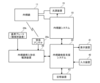
- FIG. 1 is a diagram showing an overall system configuration related to colonoscopy according to an embodiment.
- FIG. It is a figure showing an example of the endoscope used in this embodiment.
- 1 is a diagram showing a configuration example of an endoscopy support system according to an embodiment. It is a figure showing example 1 of a screen displayed on a display device. It is a figure which shows the example 2 of a screen displayed on a display apparatus. It is a figure which shows the example 3 of a screen displayed on a display apparatus. It is a figure which shows the example 4 of a screen displayed on a display apparatus. It is a figure which shows the example 5 of a screen displayed on a display apparatus. It is a figure which shows the example 6 of a screen displayed on a display apparatus.
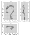
- FIGS. 10(a) to 10(c) are diagrams showing examples in which a plurality of endoscope shapes are displayed as trigonometric projections from three directions.
- FIG. 3 is a diagram showing an example of a bird's-eye perspective view of the shape of the three-dimensional endoscope when it reaches the cecum. It is a flowchart which shows the operation
- This embodiment relates to colonoscopy.
- colonoscopy an endoscope is inserted into the cecum, and upon removal, screening for lesions, examination of the lesions, and treatment of the lesions are performed.
- the location of the lesion is recorded to facilitate subsequent treatment and post-treatment follow-up.
- follow-up observation may be performed to see if the area changes to a disease, and the location of the area may be recorded as a lesion candidate.
- the large intestine is approximately 1 to 1.5 meters long and is easily deformed.
- the insertion length from the anus to the same lesion varies greatly depending on the insertion method at the time of insertion. Even if the same doctor tries, re-access may not be possible. Although re-access may be performed at other facilities from a specialist standpoint, it is more difficult for other doctors to re-access the site.
- a schema diagram of the large intestine and the approximate location of the lesion may be included in the referral letter, but the lesion is often not found even if the schema diagram is re-accessed. Therefore, information regarding lesion locations exchanged between doctors and facilities is only for reference. From the above, it is required to indicate a lesion position or a lesion candidate position with good reproducibility.
- FIG. 1 is a diagram showing the overall system configuration related to colonoscopy according to an embodiment.
- an endoscope system 10 an endoscope 11, a light source device 15, an endoscope position detection unit (UPD) 20, an endoscope examination support system 30, a display device 41, An input device 42 and a storage device 43 are used.
- the endoscope 11 according to the present embodiment is a colonoscope inserted into the large intestine of a subject (patient).
- the endoscope 11 includes a lens and a solid-state image sensor (for example, a CMOS image sensor, a CCD image sensor, or a CMD image sensor).
- the solid-state image sensor converts the light focused by the lens into an electrical signal, and outputs it to the endoscope system 10 as an endoscopic image (electrical signal).
- Endoscope 11 includes a forceps channel. An operator (doctor) can perform various treatments during an endoscopy by passing a treatment tool through the forceps channel.
- the light source device 15 includes a light source such as a xenon lamp, and supplies observation light (white light, narrowband light, fluorescence, near-infrared light, etc.) to the tip of the endoscope 11.
- the light source device 15 also has a built-in pump that sends water and air to the endoscope 11.
- the endoscope system 10 controls the light source device 15 and processes endoscopic images input from the endoscope 11.
- the endoscope system 10 can perform, for example, Narrow Band Imaging (NBI), Red Dichromatic Imaging (RDI), Texture and Color Enhancement Imaging (TXI), and Extended Depth of Field (TXI). It is equipped with functions such as EDOF (Extended Depth of Field).
- Narrow Band Imaging Narrow Band Imaging
- RDI Red Dichromatic Imaging
- TXI Texture and Color Enhancement Imaging
- TXI Texture and Color Enhancement Imaging
- TXI Extended Depth of Field
- EDOF Extended Depth of Field
- Narrowband light observation uses specific wavelengths of violet (415 nm) and green (540 nm), which are strongly absorbed by hemoglobin in the blood, to highlight capillaries and microstructures in the surface layer of the mucous membrane. A mirror image can be obtained.
- violet 415 nm
- green 540 nm
- Structural color enhancement generates an endoscopic image in which the three elements of the mucosal surface, ⁇ structure,'' ⁇ tone,'' and ⁇ brightness,'' are optimized under normal light observation.
- the endoscope system 10 uses an endoscopic image obtained by processing an endoscopic image input from the endoscope 11, or an endoscopic image input from the endoscope 11 as it is, to the endoscopy support system 30. Output to.
- the endoscope insertion shape observation device 20 is a device for observing the three-dimensional shape of the endoscope 11 inserted into the lumen of the subject.
- a receiving antenna 20a is connected to the endoscope insertion shape observation device 20.
- the receiving antenna 20a is an antenna for detecting a magnetic field generated by a plurality of magnetic coils built into the endoscope 11.
- FIG. 2 is a diagram showing an example of the endoscope 11 used in this embodiment.
- the endoscope 11 has an elongated tubular insertion section 11a made of a flexible member, and an operation section 11e connected to the proximal end of the insertion section 11a.
- the insertion portion 11a has, from the distal end side to the proximal end side, a hard distal end portion 11b, a curved portion 11c, and a flexible tube portion 11d.
- the proximal end of the rigid tip portion 11b is connected to the distal end of the curved portion 11c, and the proximal end of the curved portion 11c is connected to the proximal end of the flexible tube portion 11d.
- the operating part 11e has a main body part 11f from which a flexible tube part 11d extends, and a grip part 11g connected to the base end of the main body part 11f.
- the grip portion 11g is gripped by the operator.
- a universal cord including an imaging electric cable, a light guide, etc. extending from inside the insertion section 11a extends from the operation section 11e, and is connected to the endoscope system 10 and the light source device 15.
- the rigid tip portion 11b is the tip of the insertion portion 11a and is also the tip of the endoscope 11.
- a solid-state image sensor, an illumination optical system, an observation optical system, etc. are built into the rigid tip portion 11b. Illumination light emitted from the light source device 15 is propagated along the light guide to the distal end surface of the rigid distal end portion 11b, and is irradiated from the distal end surface of the rigid distal end portion 11b toward an observation target within the lumen.
- the curved portion 11c is constructed by connecting node rings along the longitudinal axis direction of the insertion portion 11a.
- the curved portion 11c is curved in a desired direction in response to the operator's operation input to the operating portion 11e, and the position and orientation of the rigid distal end portion 11b are changed in accordance with the curvature.
- the flexible tube portion 11d is a tubular member extending from the main body portion 11f of the operating portion 11e, has desired flexibility, and is bent by external force. The operator inserts the insertion section 11a into the large intestine of the subject while bending the bending section 11c and twisting the flexible tube section 11d.
- a plurality of magnetic coils 12 are arranged inside the insertion portion 11a at predetermined intervals (for example, 10 cm intervals) along the longitudinal direction. Each magnetic coil 12 generates a magnetic field when supplied with current.
- the plurality of magnetic coils 12 function as a position sensor for detecting each position of the insertion portion 11a.
- the receiving antenna 20a receives magnetic fields transmitted from a plurality of magnetic coils 12 built into the insertion section 11a of the endoscope 11, and outputs the magnetic fields to the endoscope insertion shape observation device 20.
- the endoscope insertion shape observation device 20 applies the magnetic field strength of each of the plurality of magnetic coils 12 received by the receiving antenna 20a to a predetermined position detection algorithm, and determines the three-dimensional position of each of the plurality of magnetic coils 12. Estimate.
- the endoscope insertion shape observation device 20 generates a three-dimensional endoscope shape of the insertion portion 11a of the endoscope 11 by performing curve interpolation on the estimated three-dimensional positions of the plurality of magnetic coils 12.
- the reference plate 20b is attached to the subject (for example, the abdomen of the subject).
- a body position sensor for detecting the body position of the subject is arranged on the reference plate 20b.
- a three-axis acceleration sensor or a gyro sensor can be used as the body position sensor.
- the reference plate 20b is connected to the endoscope insertion shape observation device 20 by a cable, and the reference plate 20b internally collects three-dimensional posture information indicating the posture of the reference plate 20b (that is, the posture of the subject). It is output to the mirror insertion shape observation device 20.
- a plurality of magnetic coils similar to the plurality of magnetic coils 12 built into the insertion section 11a of the endoscope 11 may be used as the body position sensor disposed on the reference plate 20b.
- the receiving antenna 20a receives the magnetic field transmitted from the plurality of magnetic coils arranged on the reference plate 20b, and outputs it to the endoscope insertion shape observation device 20.
- the endoscope insertion shape observation device 20 applies the magnetic field strength of each of the plurality of magnetic coils received by the receiving antenna 20a to a predetermined attitude detection algorithm to determine the attitude of the reference plate 20b (i.e., the attitude of the subject). ) is generated.
- the endoscope insertion shape observation device 20 changes the generated three-dimensional endoscope shape to follow changes in the three-dimensional posture information. Specifically, the endoscope insertion shape observation device 20 changes the three-dimensional endoscope shape so as to cancel out the change in the three-dimensional posture information. As a result, even if the subject's body position is changed during endoscopy, the endoscope shape is always maintained from a specific viewpoint (for example, the perspective of viewing the subject's abdomen vertically from the front side of the abdomen). can be recognized.
- a specific viewpoint for example, the perspective of viewing the subject's abdomen vertically from the front side of the abdomen.
- the endoscope insertion shape observation device 20 measures the insertion length indicating the length of the portion of the endoscope 11 inserted into the large intestine, and the elapsed time since the endoscope 11 was inserted into the large intestine (hereinafter referred to as insertion time). ) can be obtained.
- the endoscope insertion shape observation device 20 measures the insertion length using the position of the timing at which the operator inputs the examination start operation into the input device 42 as a reference point, and measures the insertion time using the timing as the starting point.
- the endoscope insertion shape observation device 20 estimates the position of the anus from the generated three-dimensional endoscope shape and the difference in magnetic field strength between the magnetic coil inside the body and the magnetic field coil outside the body, and the estimated anus position.
- the position may be used as the base point of the insertion length.
- an encoder may be installed near the anus of the subject.
- the endoscope insertion shape observation device 20 detects the insertion length based on the anus position based on the signal from the encoder.
- the endoscope insertion shape observation device 20 adds the insertion length and insertion time to the 3D endoscope shape after body position correction based on the 3D posture information, and outputs the result to the endoscopy support system 30.
- the endoscopy support system 30 performs endoscopy based on the endoscope image input from the endoscope system 10 and the endoscope shape input from the endoscope insertion shape observation device 20. Generate support information and present it to the operator. Furthermore, the endoscopy support system 30 uses the endoscope image inputted from the endoscope system 10 and the endoscope shape inputted from the endoscope insertion shape observation device 20 to Inspection history information is generated and recorded in the storage device 43.
- the display device 41 includes a liquid crystal monitor or an organic EL monitor, and displays images input from the endoscopy support system 30.
- the input device 42 includes a mouse, a keyboard, a touch panel, etc., and outputs operation information input by a surgeon or the like to the endoscopy support system 30.
- the storage device 43 includes a storage medium such as an HDD or an SSD, and stores endoscopy history information generated by the endoscopy support system 30.
- the storage device 43 may be a dedicated storage device attached to the endoscope system 10, a database in an in-hospital server connected via an in-hospital network, or a database in a cloud server. It may be.
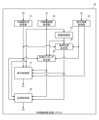
- FIG. 3 shows a configuration example of an endoscopy support system 30 according to an embodiment.
- the endoscopy support system 30 may be constructed with a processing device dedicated to endoscopy support, or may be constructed with a general-purpose server (which may be a cloud server). Furthermore, the endoscopy support system 30 may be constructed with any combination of a processing device dedicated to endoscopy support, a general-purpose server (which may be a cloud server), and a dedicated image diagnostic device. . Further, the endoscopy support system 30 may be constructed integrally with the endoscope system 10.
- the endoscope shape acquisition unit 31 acquires the endoscope shape from the endoscope insertion shape observation device 20.
- the endoscope shape also includes information on insertion length and insertion time.
- the endoscopic image acquisition unit 32 acquires endoscopic images from the endoscope system 10.
- the image recognition unit 34 has a plurality of machine learning models for detecting the site of the large intestine, the state within the large intestine lumen, and lesions from the endoscopic image.
- a plurality of machine learning models are generated by machine learning using a large number of endoscopic images each annotated with various parts, various states, and various lesions as a supervised data set.
- the annotation is provided by an annotator with specialized knowledge such as a doctor.
- CNN, RNN, LSTM, etc. which are types of deep learning, can be used.
- the parts of the large intestine can be broadly classified into the rectum, sigmoid colon, descending colon, transverse colon, ascending colon, and cecum, in order from the anal side.
- the image recognition unit 34 can input the endoscopic image to the region learning model and detect the region of the large intestine from the endoscopic image. At this time, the image recognition unit 34 may identify the region based on the detection results of a plurality of chronologically consecutive endoscopic images. For example, when the same region is detected in a set number or more of consecutive endoscopic images of 30 frames or 60 frames, the image recognition unit 34 specifies the region as an officially detected region.
- the image recognition unit 34 may identify the region by considering the anteroposterior relationship of the detected region or the shape of the endoscope acquired from the endoscope insertion shape observation device 20.
- the image recognition unit 34 identifies, for example, whether the direction of movement of the endoscope 11 is the insertion direction (anus ⁇ cecum) or the removal direction (cecum ⁇ anus). In the case of the insertion direction, the image recognition unit 34 switches the detection site from the descending colon to the transverse colon when the left colon flexure is detected, and switches the detection site from the transverse colon to the ascending colon when the right colon flexure is detected. Switch.
- the image recognition unit 34 switches the detection site from the ascending colon to the transverse colon when the right colonic flexure is detected, and switches the detection site from the transverse colon to the descending colon when the left colonic flexure is detected. Switch.
- the image recognition unit 34 takes into account the three-dimensional position of the rigid tip portion 11b (hereinafter referred to as the endoscope tip portion) based on the endoscope shape obtained from the endoscope insertion shape observation device 20.
- the accuracy of part detection may be improved.
- the image recognition unit 34 discards the detection result based on image recognition when the position of the endoscope tip estimated from the shape of the endoscope and the position of the detected part based on image recognition are inconsistent.
- the image recognition unit 34 can also input the endoscopic image into the intraluminal state learning model and determine the intraluminal state from the endoscopic image.
- the image recognition unit 34 can detect, for example, the presence or absence of folds of a predetermined height or more, and the presence or absence of diverticula.
- the image recognition unit 34 can also input endoscopic images to the lesion learning model and detect lesion candidates from the endoscopic images.
- the image recognition unit 34 may check the image quality of the endoscopic image prior to image recognition of the detection target.
- the image recognition unit 34 excludes endoscopic images that are determined to have poor image quality (for example, blur, out of focus, abnormal brightness (for example, halation)) from image recognition targets of detection targets.
- the reference position determination unit 35 determines the shape of the endoscope to be set as the reference position from the shape of the endoscope that is continuously acquired from the endoscope insertion shape observation device 20.
- the reference position is determined to be the position when the deepest part is reached during colonoscopy. Usually, the deepest part of the colonoscopy is the cecum. Note that depending on the operator, the endoscope 11 may be inserted up to the ileum. Furthermore, depending on the subject, the endoscope 11 may not be able to be inserted into the cecum, and the ascending colon may be the deepest part of the colonoscopy.
- the reference position determination unit 35 determines the position when the insertion length obtained from the endoscope insertion shape observation device 20 is the longest as the position when the deepest part is reached. Further, the reference position determination unit 35 may determine the imaging position of the endoscopic image in which the cecum is detected by the image recognition unit 34 as the position when the deepest part is reached. Further, the reference position determination unit 35 may determine the position at the timing when the operator inputs the insertion completion operation into the input device 42 as the position when the deepest part is reached.
- the recording timing determination unit 36 determines the recording timing of the endoscopic image and the shape of the endoscope.
- the recording timing determination unit 36 determines, for example, the timing at which the operator presses the photographing button (release button) of the operation unit 11e as the recording timing. Note that if a microphone is installed in the operator's throat or the like, the operator can also instruct the recording timing by voice. Furthermore, the recording timing determining unit 36 may determine the recording timing to be the timing at which the endoscopic image in which the lesion candidate is detected is captured by the image recognizing unit 34 .
- the recording timing determination unit 36 may automatically determine the recording timing based on a predetermined rule. Automatic recording of endoscopic images and endoscopic shapes is utilized to generate examination digests. Generally, in colonoscopy, the endoscope 11 is inserted into the cecum and then removed toward the anus while observation and treatment are performed. For example, the recording timing determining unit 36 may set the recording timing every time the insertion length increases by a predetermined interval (for example, several cm). Further, the recording timing determining unit 36 may set the recording timing every time the removal time elapses for a predetermined period of time.
- a predetermined interval for example, several cm
- the recording timing determining unit 36 may change the frequency of automatic recording depending on the site or intraluminal state detected by the image recognition unit 34. For example, the recording timing determining unit 36 increases the frequency of automatic recording while passing through a region where lesions are likely to occur. Furthermore, the recording timing determining unit 36 increases the frequency of automatic recording while passing through a location where the intraluminal condition is poor. Note that the areas to be automatically recorded may be set in advance based on the past history and epidemiological knowledge of the subject.
- the recording timing determining unit 36 may determine as the recording timing at least one or all of the timing based on the operator's operation, the timing based on the detection of a lesion candidate by the image recognition unit 34, and the timing based on automatic settings. good.
- the display control unit 37 When displaying examination information including endoscopic images, the display control unit 37 simultaneously displays two endoscope shapes: the endoscope shape when reaching the deepest part and the endoscope shape at a specific recording timing. 41. Note that the display control unit 37 may display the two endoscope shapes when a predetermined operation is input to the input device 42. The display control unit 37 may display the two endoscope shapes in one graph, or may display them side by side in two graphs.
- the display control unit 37 can display the two endoscope shapes in real time during the examination.
- the display control unit 37 superimposes a mark surrounding the lesion candidate on the endoscopic image in which the lesion candidate is detected. This makes it possible to reduce the risk of missing a lesion. Note that an alert sound may be output from a speaker.
- the subject may change his or her body position or move slightly on his or her own in accordance with the operator's instructions.
- the body position change is performed to facilitate insertion of the endoscope 11 and observation. Therefore, the position and orientation of the endoscope may deviate from the coordinate space based on the position and orientation of the examination room or examination table (bed).
- the reference plate 20b is attached to the subject, the position and orientation of the subject are detected, and the position and orientation of the endoscope shape are corrected based on the detection results.
- the position and orientation of the endoscope shape can be corrected by matching the colon lumen arrangement model with the endoscope shape. This is particularly effective during removal because the shape of the insertion portion 11a generally matches the arrangement of the large intestine lumen. This correction may be performed by the endoscope insertion shape observation device 20 or may be performed by the endoscopy support system 30.
- the recording control unit 38 stores the examination information including the endoscopic images acquired during the examination in the storage device 43 by associating the shape of the endoscope when reaching the deepest part with the shape of the endoscope at at least one recording timing. Record. Since the shape of the endoscope when reaching the deepest part is common in one case, it is only necessary to record it in association with the case. Note that the format of the endoscope shape data to be recorded does not matter. For example, it may be a mathematical formula for calculating the shape, point cloud data for indicating the shape, or image data viewed from one or more directions.
- the examination information recorded in the storage device 43 is read out to the endoscopy support system 30.
- the display control unit 37 displays two types of endoscope shapes on the display device 41: the endoscope shape at the time of reaching the deepest point associated with the examination information, and the endoscope shape at at least one recording timing.
- the test information may be displayed on the monitor of another PC after appropriately selecting the test information, changing the format, or transferring the test information to another database.
- two types of endoscope shapes are simultaneously displayed on the monitor: the endoscope shape when reaching the deepest part and the endoscope shape at at least one recording timing.
- the display control unit 37 and the recording control unit 38 respectively display the first endoscope shape when the endoscope tip is located at a predetermined position and the shape of the endoscope in endoscopy. It is possible to acquire an endoscopic image taken during the examination and the shape of the second endoscope when the endoscopic image was taken. This allows the endoscopic image to be divided into the shape of the second endoscope when the endoscopic image was taken and the shape of the first endoscope when the endoscope tip is located at a predetermined location. It becomes possible to present the shape and the shape at the same time.
- the first endoscope shape and the second endoscope shape are different shapes from each other.
- the predetermined region may be the deepest region during endoscopy.
- the shape of the endoscope when the distal end portion of the endoscope is located at the deepest point can be determined to be the first shape of the endoscope.
- the predetermined site may be the cecum. In this case, it is possible to determine the shape of the first endoscope when the deepest part during endoscopy is the cecum.
- the insertion portion 11a of the endoscope 11 is inserted into the tortuous intestinal tract of the large intestine.
- the insertion shape of the endoscope 11 may change even in the same patient due to differences in doctors or insertion techniques, or due to differences in the insertion shape of the endoscope 11 for each examination due to changes in the position of the unfixed intestinal section in the body, expansion and contraction, etc. can change.
- the internal arrangement of parts fixed to the patient's body such as the ascending colon and descending colon, does not change significantly.
- the end of the large intestine, the caecum is located at the end of these fixed parts, and its position within the body does not change much.
- the caecum is the deepest part of the large intestine, and is the area that doctors aim to reach during colonoscopy.
- the endoscope 11 may be inserted as far as the ileum, which is the end of the small intestine, but the cecum can serve as a relatively stable reference point during examinations because it is located at the end of the ascending colon, which is a fixed part. This is one of the parts.
- the deepest part is one of the sites that can serve as a reference point.
- the endoscope 11 when the endoscope 11 is removed from the deepest part, for example, the cecum, even if the intestinal tract is inserted in a bent manner, the bent portion is lengthened and the degree of bending is reduced. As a result, the intestinal tract at the time of removal takes on a shape with less curvature, based on its original arrangement. It is thought that the shape and arrangement of the intestinal tract will become more stable than at the time of insertion. At this time, the tip of the insertion portion 11a of the endoscope 11 is considered to take a route or draw a trajectory with less variation than when inserted.
- the route or trajectory is approximately determined by the following.
- the reference position determination unit 35 determines that the endoscope tip is located at a predetermined location based on at least one of the endoscopic image, the shape of the endoscope, and the insertion length of the endoscope.
- the display control unit 37 and the recording control unit 38 each acquire the endoscope shape when the endoscope tip is located at a predetermined location as the first endoscope shape. In this case, the first endoscope shape can be automatically acquired.
- the display control unit 37 and the recording control unit 38 each define the endoscope shape at the timing when the reference position determination unit 35 acquires the endoscope insertion completion signal based on the operator's operation as the first endoscope shape. You may also obtain it as In this case, it is possible to obtain the first endoscope shape that matches the operator's intention.
- the recording control unit 38 records the first endoscope shape, the photographed endoscopic image, and the second endoscope shape corresponding to the endoscope image in the storage device 43 in association with each other. be able to. According to this, after an examination, the endoscopic image is divided into the second endoscope shape when the endoscopic image was taken and the second endoscope shape when the endoscope tip is located at a predetermined position. It becomes possible to present the endoscope shape of 1 at the same time.
- the display control unit 37 can display the first endoscope shape and the second endoscope shape on the display device 41 at the same time. According to this, the operator or doctor can intuitively grasp the relative position of the second endoscope shape when the endoscopic image is taken. At this time, the display control unit 37 can display the first endoscope shape and the second endoscope shape on one graph. According to this, the operator or doctor can more accurately grasp the relative position of the second endoscope shape when the endoscopic image is taken. Furthermore, the display control unit 37 can simultaneously display the first endoscope shape, the second endoscope shape, and the endoscopic image corresponding to the second endoscope shape on the display device 41. can. According to this, the operator or doctor can simultaneously grasp the endoscopic image and the relative position of the second endoscope shape when the endoscopic image was taken.
- the placement of the tip of the first endoscope shape and the tip of the second endoscope shape on the intestinal tract is displayed with relatively high reproducibility. Therefore, based on the first endoscope shape placed deeper and its tip position, the tip of the second endoscope shape is changed from the second endoscope shape at the position where it is removed from that position. The position and arrangement within the intestinal tract can be confirmed with relatively good reproducibility. These results can be checked during and after the test. Therefore, it becomes position specifying information when recording the position of a lesion, etc. during an examination, and can serve as guide information with good reproducibility when approaching the same lesion, etc. during subsequent examinations or treatments. In particular, by using images taken when the endoscope is in the second shape, it becomes easier to identify the location of the lesion, approach it again, and more accurately determine the location. Become.
- the second endoscope shape is obtained when inserting the endoscope 11, it is possible to record it by comparing it with the shape when it reaches the deepest part or the cecum, as a record when inserting into a difficult-to-insert site. It is useful as a record of individual examinations and patients in that it can be confirmed along with the tip position, insertion shape, and events at that position.
- FIG. 4 is a diagram showing example 1 of the screen displayed on the display device 41.
- the following example screen assumes a screen example when a doctor confirms test information after an examination, but a similar screen display is also possible during the examination.
- a similar screen display is also possible during the examination.
- the endoscope shape B1 at the time of reaching the cecum and the plurality of endoscope shapes B2 to B8 at the time of imaging are displayed simultaneously on the graph placed in the center.
- the display control unit 37 aligns and displays a specific portion of the endoscope shape B1 and specific portions of the plurality of endoscope shapes B2 to B8.
- the specific portion may be a site corresponding to the insertion port of the subject into which the endoscope 11 is inserted (in the case of colonoscopy, the anus).
- the plurality of endoscope shapes B2 to B8 (second endoscope shape) at the time of imaging are It can be placed in a position that matches the actual situation.
- Marks C1 to C8 indicating imaging positions are added to the distal ends of the endoscope shape B1 when reaching the cecum and the plurality of endoscope shapes B2 to B8 during imaging, respectively.
- a plurality of endoscopic images A1-A8 are displayed surrounding a graph placed in the center.
- the endoscopic image A1 on the lower left is an endoscopic image when the cecum is reached, and a plurality of endoscopic images A2 to A8 are arranged clockwise in order of the removal direction.
- the insertion length and insertion time are displayed in each of the endoscopic images A1 to A8.
- the display control unit 37 acquires the plurality of endoscopic images A2-A8 and the plurality of endoscopic shapes B2-B8 corresponding to the plurality of endoscopic images A2-A8, respectively, and displays the plurality of endoscopic images A2. -A8 and the plurality of endoscope shapes B2-B8 are displayed on the display device 41 at the same time as the endoscope shape B1. Displaying a list of multiple endoscope images A2-A8, multiple endoscope shapes B2-B8 (second endoscope shape), and endoscope shape B1 (first endoscope shape). This makes it easier for surgeons and doctors to understand the overall picture of endoscopy.
- the display control unit 37 estimates the change in the position and orientation of the subject from the change in the acquired endoscope shape, and performs the estimation. Based on the results, the endoscope shape B1 and the plurality of endoscope shapes B2-B8 are aligned and faced. The display control unit 37 simultaneously displays the endoscope shape B1 and the plurality of endoscope shapes B2-B8 on the display device 41 after alignment and facing. According to this, the endoscope shape B1 (first endoscope shape) when reaching the cecum and the plurality of endoscope shapes B2 to B8 (second endoscope shape) at the time of imaging are compared to the actual situation. It is possible to continuously display the shape of the endoscope from a specific viewpoint (for example, a viewpoint viewing the abdomen of the subject perpendicularly from the front side of the abdomen) while arranging it in a regular position.
- a specific viewpoint for example, a viewpoint viewing the abdomen of the subject perpendicularly from the front side of the abdomen
- lesion candidates are detected in three endoscopic images A2, A3, and A6.
- Marks D2, D3, and D6 surrounding the respective lesion candidates are superimposed on the three endoscopic images A2, A3, and A6.
- mark C1-C8 indicating the imaging positions of multiple endoscope shapes B1-B8
- endoscope shapes B1, B4- are associated with endoscope images A1, A4-A5, and A7-A8 in which no lesion candidate is detected.
- Marks C1, C4-C5, and C7-C8 indicating the imaging positions of B5 and B7-B8 are displayed as round marks, and the endoscopes are linked to the endoscopic images A2, A3, and A6 in which lesion candidates are detected.
- Marks C2, C3, and C6 indicating the photographing positions of shapes B2, B3, and B6 are displayed as star marks.
- the display control unit 37 displays endoscopic images A2, A3, and A6 in which lesion candidates are detected, and an endoscope shape B2 when the endoscopic images A2, A3, and A6 in which lesion candidates are detected are captured. B3 and B6 are acquired. According to this, it is possible to obtain a highly important endoscopic image using the shape of the endoscope as a display target.
- the display control unit 37 displays the endoscope shapes B2, B3, and B6, and the marks C2, C3, and C6 that indicate that a lesion candidate has been detected and are placed at the distal ends of the endoscope shapes B2, B3, and B6. It is displayed on the display device 41 at the same time. According to this, the operator or doctor can more easily grasp the imaging position of the endoscopic image in which the lesion candidate is detected.
- the shape of the endoscope with the subject in a supine position on the examination table is shown from the ceiling perspective.
- the shape of the endoscope viewed from two or three directions may be displayed, or the shape of the endoscope viewed from an oblique direction may be displayed in a perspective view.
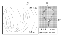
- FIG. 5 is a diagram showing a second example screen displayed on the display device 41.
- Screen example 2 is a screen example that changes when endoscopic image A7 is selected by a user such as a doctor by a click operation or a touch operation in screen example 1 shown in FIG. 4.
- the endoscopic image A7 that has been noticed by the user is displayed, and on the right side of the screen, the endoscope shape B7 when capturing the endoscopic image A7 and the endoscope shape B1 when reaching the cecum are displayed.
- a single graph is displayed in which both are plotted at the same time.
- the insertion length (18 [cm]) when the endoscopic image A7 was captured and the insertion length (68 [cm]) when reaching the cecum are displayed below the graph. Note that the graph and insertion length table on the right side may be displayed only when the user performs a predetermined operation on the endoscopic image A7 in order to simplify the screen display.
- the display control unit 37 displays an endoscopic image A7 selected by the user from the plurality of endoscopic images A2-A8 and an endoscope shape B7 corresponding to the selected endoscopic image A7. It is displayed on the display device 41 at the same time as the shape B1. According to this, it is possible to generate a screen that focuses on the information of the endoscopic image that the user is interested in.
- the display control unit 37 displays the insertion length corresponding to the endoscope shape B1 and the insertion length corresponding to the endoscope shape B7 on the display device 4 at the same time as the endoscope shape B1 and the endoscope shape B7. may be displayed. By displaying the insertion length at the same time, the amount of information presented to the user can be increased.
- the display control unit 37 displays the insertion time corresponding to the endoscope shape B1 and the insertion time corresponding to the endoscope shape B7 on the display device 41 at the same time as the endoscope shape B1 and the endoscope shape B7. You may. By displaying the insertion time at the same time, the amount of information presented to the user can be increased.
- FIG. 6 is a diagram showing a third example screen displayed on the display device 41.
- screen example 3 only the endoscope shape B11 when reaching the cecum is displayed on the three-dimensional graph placed in the center.
- a plurality of endoscopic images A11 to A21 are displayed surrounding a graph placed in the center.
- the plurality of endoscopic images A11-A21 may be thumbnail images.
- the endoscopic image A11 on the lower left is an endoscopic image when the cecum is reached, and a plurality of endoscopic images A12 to A21 are arranged clockwise in the order of the removal direction.
- Marks C11-C21 are added to the endoscope shape B11 when the endoscope reaches the cecum, indicating the respective imaging positions of the plurality of endoscopic images A11-A21.
- FIG. 7 is a diagram showing example 4 of the screen displayed on the display device 41.
- Screen example 4 is a screen example that changes when the user selects endoscopic image A18 in screen example 3 shown in FIG.
- the endoscopic image A18 that has been noticed by the user is displayed, and on the right side of the screen, the endoscope shape B18 when capturing the endoscopic image A18 and the endoscope shape B11 when reaching the cecum are displayed.
- a single graph is displayed in which both are plotted at the same time.
- the insertion length (23 [cm]) at the time of capturing the endoscopic image A18 is displayed below the graph. Note that the screen example shown in FIG. 6 and the screen example shown in FIG. 7 may be displayed on one screen.
- the display control unit 37 shows the endoscope shape B11, the plurality of endoscopic images A11-A21, and the shooting positions of each of the plurality of endoscopic images A11-A21 arranged on the endoscope shape B11.
- a first display mode in which marks C11 to C21 are displayed on the display device 41, an endoscope image A18 selected by the user, an endoscope shape B18 corresponding to the selected endoscope image A18, and an endoscope shape B18 corresponding to the selected endoscope image A18. It is possible to switch between a second display mode in which the endoscope shape B11 and the endoscope shape B11 are simultaneously displayed on the display device 41. According to this, visibility or operability for the user can be improved.
- FIG. 8 is a diagram showing screen example 5 displayed on the display device 41.
- an insertion length straight line E1 generated by straightening the endoscope shape B11 when reaching the cecum shown in FIG. are displayed in parallel with the insertion long line E1.
- the plurality of endoscopic images A11-A21 may be thumbnail images.
- the leftmost endoscopic image A11 is an endoscopic image when the cecum is reached, and a plurality of endoscopic images A12 to A21 are arranged toward the right in the order of the removal direction.
- Marks C11-C21 are added on the insertion length straight line E1 to indicate the respective imaging positions of the plurality of endoscopic images A11-A21.
- the display control unit 37 displays the endoscope shape B11, the plurality of endoscopic images A11-A21, and the plurality of endoscopic images arranged on the insertion length straight line E1 generated by linearizing the endoscope shape B11. It is possible to switch between a third display mode in which marks C11-C21 indicating the shooting positions of A11-A21 are displayed on the display device 41, and the second display mode. According to this, visibility or operability for the user can be improved.
- FIG. 9 is a diagram showing screen example 6 displayed on the display device 41.
- an insertion time straight line E2 generated by linearizing the endoscope shape B11 when reaching the cecum shown in FIG. 6 is displayed, and above the insertion time straight line E2, a plurality of endoscopic images A11-A21 are displayed. are displayed in parallel with the insertion time straight line E2.
- the plurality of endoscopic images A11-A21 may be thumbnail images.
- the leftmost endoscopic image A11 is an endoscopic image when the cecum is reached, and a plurality of endoscopic images A12 to A21 are arranged toward the right in the order of the removal direction.
- Marks C11-C21 are added on the insertion time straight line E2 to indicate the imaging timing of each of the plurality of endoscopic images A11-A21.
- the insertion time when the cecum is reached is 4:26 after the start of insertion, and the insertion time is counted up from there until the removal is completed.
- the screen changes to the example screen shown in FIG. 7.
- the display control unit 37 displays the endoscope shape B11, the plurality of endoscopic images A11-A21, and the plurality of endoscopic images arranged on the insertion time straight line E2 generated by linearizing the endoscope shape B11. It is possible to switch between a fourth display mode in which marks C11-C21 indicating the respective photographing timings of A11-A21 are displayed on the display device 41, and the second display mode. According to this, visibility or operability for the user can be improved.
- FIGS. 10(a) to 10(c) are diagrams showing examples in which a plurality of endoscope shapes are displayed as trigonometric projection views from three directions.
- the y direction is the longitudinal direction
- the x direction is the lateral direction
- the z direction is the thickness direction of the subject in the supine position.
- FIG. 10(a) shows an example in which a plurality of endoscope shapes are plotted on xy coordinates.
- the left side of the x-axis is the direction of the right flank
- the right side of the x-axis is the direction of the left flank
- the upper side of the y-axis is the direction of the chest
- the lower side of the y-axis is the direction of the foot.
- FIG. 10(b) shows an example in which a plurality of endoscope shapes are plotted on the zy coordinate.
- the left side of the z-axis is the direction of the abdomen
- the right side of the z-axis is the direction of the back
- the upper side of the y-axis is the direction of the chest
- the lower side of the y-axis is the direction of the feet.
- FIG. 10(c) shows an example in which a plurality of endoscope shapes are plotted on xz coordinates.
- the left side of the x-axis is the direction of the right flank
- the right side of the x-axis is the direction of the left flank
- the upper side of the z-axis is the direction of the abdomen
- the lower side of the z-axis is the direction of the back.
- FIG. 11 is a diagram showing an example of a bird's-eye perspective view of the three-dimensional endoscope shape B31 when the endoscope reaches the cecum.
- a coordinate system is used in which the origin is the position corresponding to the anus, which is the starting point of insertion into the body.
- the coordinate system has memory for actual dimensions.
- the direction and scale of the viewpoint can be appropriately changed and set to the direction and size desired by the operator to confirm the three-dimensional endoscope shape B31.
- a plurality of endoscope shapes at the time of imaging as shown in FIG. 4 may also be displayed simultaneously on the same three-dimensional graph.
- the coordinate system and dimensions may be displayed in any manner. For example, the coordinate system may not be displayed, the origin may not be the anus position, the dimensions may not be displayed, or only the scale may be displayed.
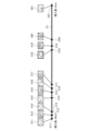
- FIG. 13 is a flowchart illustrating an example of the operation of the endoscopy support system 30 according to the embodiment when confirming examination information.
- the display control unit 37 displays the shape of the endoscope at the time of reaching the deepest point, the plurality of endoscopic images taken by the operator, and the plurality of endoscopic images corresponding to the respective shooting timings, which are recorded in association with the storage device 43.
- the endoscope shape is read from the storage device 43 (S20).
- the display control unit 37 displays a digest of the plurality of read endoscopic images on the display device 41 (S21).
- the display control unit 37 displays the endoscopic image selected by the user, the shape of the endoscope corresponding to the endoscopic image, and the shape of the endoscope when reaching the deepest part on the display device 41 (S22). .
- the lesion or lesion candidate can be re-accessed with the endoscope 11. It becomes easier to do. The operator can more accurately grasp the position within the colon lumen where a lesion or lesion candidate exists, and re-access becomes easier. Further, by employing the various display forms described above, visibility or operability for the user can be improved.
- a plurality of shape sensors may be built into the endoscope 11 to estimate the shape of the endoscope.
- the shape sensor may be, for example, a fiber sensor that detects the bent shape from the curvature of a specific location using an optical fiber.
- the fiber sensor has, for example, an optical fiber arranged along the longitudinal direction of the insertion section 11a, and the optical fiber is provided with a plurality of photodetectors along the longitudinal direction. Detection light is supplied from the detection light emitting device to the optical fiber, and the shape of the endoscope is estimated based on changes in the amount of light detected by each photodetector while the detection light is propagating through the optical fiber.
- the present disclosure can be used for colonoscopy.
Landscapes
- Health & Medical Sciences (AREA)
- Life Sciences & Earth Sciences (AREA)
- Surgery (AREA)
- Engineering & Computer Science (AREA)
- Veterinary Medicine (AREA)
- General Health & Medical Sciences (AREA)
- Public Health (AREA)
- Biomedical Technology (AREA)
- Heart & Thoracic Surgery (AREA)
- Medical Informatics (AREA)
- Molecular Biology (AREA)
- Animal Behavior & Ethology (AREA)
- Physics & Mathematics (AREA)
- Biophysics (AREA)
- Pathology (AREA)
- Nuclear Medicine, Radiotherapy & Molecular Imaging (AREA)
- Optics & Photonics (AREA)
- Radiology & Medical Imaging (AREA)
- Human Computer Interaction (AREA)
- Robotics (AREA)
- Signal Processing (AREA)
- Endoscopes (AREA)
Priority Applications (4)
| Application Number | Priority Date | Filing Date | Title |
|---|---|---|---|
| JP2024508897A JP7815415B2 (ja) | 2022-03-23 | 2022-03-23 | 内視鏡検査支援システム、内視鏡検査支援システムの作動方法および記憶媒体 |
| PCT/JP2022/013531 WO2023181175A1 (ja) | 2022-03-23 | 2022-03-23 | 内視鏡検査支援システム、内視鏡検査支援方法および記憶媒体 |
| CN202280093881.9A CN118900659A (zh) | 2022-03-23 | 2022-03-23 | 内窥镜检查辅助系统、内窥镜检查辅助方法以及存储介质 |
| US18/892,693 US20250009248A1 (en) | 2022-03-23 | 2024-09-23 | Endoscopy support system, endoscopy support method, and storage medium |
Applications Claiming Priority (1)
| Application Number | Priority Date | Filing Date | Title |
|---|---|---|---|
| PCT/JP2022/013531 WO2023181175A1 (ja) | 2022-03-23 | 2022-03-23 | 内視鏡検査支援システム、内視鏡検査支援方法および記憶媒体 |
Related Child Applications (1)
| Application Number | Title | Priority Date | Filing Date |
|---|---|---|---|
| US18/892,693 Continuation US20250009248A1 (en) | 2022-03-23 | 2024-09-23 | Endoscopy support system, endoscopy support method, and storage medium |
Publications (1)
| Publication Number | Publication Date |
|---|---|
| WO2023181175A1 true WO2023181175A1 (ja) | 2023-09-28 |
Family
ID=88100382
Family Applications (1)
| Application Number | Title | Priority Date | Filing Date |
|---|---|---|---|
| PCT/JP2022/013531 Ceased WO2023181175A1 (ja) | 2022-03-23 | 2022-03-23 | 内視鏡検査支援システム、内視鏡検査支援方法および記憶媒体 |
Country Status (4)
| Country | Link |
|---|---|
| US (1) | US20250009248A1 (https=) |
| JP (1) | JP7815415B2 (https=) |
| CN (1) | CN118900659A (https=) |
| WO (1) | WO2023181175A1 (https=) |
Families Citing this family (1)
| Publication number | Priority date | Publication date | Assignee | Title |
|---|---|---|---|---|
| WO2022195696A1 (ja) * | 2021-03-16 | 2022-09-22 | オリンパスメディカルシステムズ株式会社 | 医療支援システムおよび医療支援方法 |
Citations (4)
| Publication number | Priority date | Publication date | Assignee | Title |
|---|---|---|---|---|
| JP2001046318A (ja) * | 1999-08-05 | 2001-02-20 | Olympus Optical Co Ltd | 内視鏡形状検出装置 |
| WO2018069992A1 (ja) * | 2016-10-12 | 2018-04-19 | オリンパス株式会社 | 挿入システム |
| WO2018179991A1 (ja) * | 2017-03-30 | 2018-10-04 | 富士フイルム株式会社 | 内視鏡システム及びその作動方法 |
| WO2019198322A1 (ja) * | 2018-04-10 | 2019-10-17 | オリンパス株式会社 | 医療システム |
Family Cites Families (1)
| Publication number | Priority date | Publication date | Assignee | Title |
|---|---|---|---|---|
| JP7752529B2 (ja) | 2018-10-19 | 2025-10-10 | ギブン イメージング リミテッド | 生体内画像ストリームの精査用情報を生成及び表示するためのシステム並びに方法 |
-
2022
- 2022-03-23 CN CN202280093881.9A patent/CN118900659A/zh active Pending
- 2022-03-23 JP JP2024508897A patent/JP7815415B2/ja active Active
- 2022-03-23 WO PCT/JP2022/013531 patent/WO2023181175A1/ja not_active Ceased
-
2024
- 2024-09-23 US US18/892,693 patent/US20250009248A1/en active Pending
Patent Citations (4)
| Publication number | Priority date | Publication date | Assignee | Title |
|---|---|---|---|---|
| JP2001046318A (ja) * | 1999-08-05 | 2001-02-20 | Olympus Optical Co Ltd | 内視鏡形状検出装置 |
| WO2018069992A1 (ja) * | 2016-10-12 | 2018-04-19 | オリンパス株式会社 | 挿入システム |
| WO2018179991A1 (ja) * | 2017-03-30 | 2018-10-04 | 富士フイルム株式会社 | 内視鏡システム及びその作動方法 |
| WO2019198322A1 (ja) * | 2018-04-10 | 2019-10-17 | オリンパス株式会社 | 医療システム |
Also Published As
| Publication number | Publication date |
|---|---|
| JPWO2023181175A1 (https=) | 2023-09-28 |
| CN118900659A (zh) | 2024-11-05 |
| JP7815415B2 (ja) | 2026-02-17 |
| US20250009248A1 (en) | 2025-01-09 |
Similar Documents
| Publication | Publication Date | Title |
|---|---|---|
| KR102458587B1 (ko) | 진단 검사를 실시간 치료에 통합하기 위한 범용 장치 및 방법 | |
| JP5676058B1 (ja) | 内視鏡システム及び内視鏡システムの作動方法 | |
| US10092216B2 (en) | Device, method, and non-transitory computer-readable medium for identifying body part imaged by endoscope | |
| CN103313675B (zh) | 用于内窥镜手术的术中照相机校准 | |
| JP2018537155A (ja) | 患者の体内における内視鏡の位置を追跡するための装置及び方法 | |
| CN102946784A (zh) | 用于内窥镜实时校准的系统和方法 | |
| WO2012014438A1 (ja) | 内視鏡観察を支援する装置および方法、並びに、プログラム | |
| JP2011206168A (ja) | 観察支援システムおよび方法並びにプログラム | |
| JP7441934B2 (ja) | 処理装置、内視鏡システム及び処理装置の作動方法 | |
| US20250009248A1 (en) | Endoscopy support system, endoscopy support method, and storage medium | |
| JP7462255B2 (ja) | 内視鏡用形状計測システムおよび内視鏡用形状計測方法 | |
| US20260102051A1 (en) | Endoscope control device, endoscope system, and endoscope control method | |
| JP2008119259A (ja) | 内視鏡挿入形状解析システム | |
| JP2026074170A (ja) | 内視鏡検査支援システム、内視鏡検査支援システムの作動方法 | |
| JP2020185082A (ja) | 血管径測定装置および血管径測定方法 | |
| JP7669584B2 (ja) | 内視鏡挿入支援システム、内視鏡挿入支援システムの作動方法および記憶媒体 | |
| JP7836881B2 (ja) | 内視鏡検査支援システム、内視鏡検査支援システムによる内視鏡検査支援方法および記憶媒体 | |
| WO2022230160A1 (ja) | 内視鏡システム、内腔構造算出システム及び内腔構造情報の作成方法 | |
| CN113317874A (zh) | 一种医学图像处理装置及介质 | |
| WO2021176665A1 (ja) | 手術支援システム、手術支援方法、及び、プログラム | |
| JP7264407B2 (ja) | 訓練用の大腸内視鏡観察支援装置、作動方法、及びプログラム | |
| JP7609278B2 (ja) | 画像処理装置、画像処理方法及びプログラム | |
| WO2023195103A1 (ja) | 検査支援システムおよび検査支援方法 | |
| WO2024185099A1 (ja) | 内視鏡検査支援装置、内視鏡検査支援方法、及び、記録媒体 | |
| WO2025037403A1 (ja) | 内視鏡補助情報生成装置、内視鏡補助情報生成方法、内視鏡補助情報生成プログラム、推論モデルの学習方法、および内視鏡補助システム |
Legal Events
| Date | Code | Title | Description |
|---|---|---|---|
| 121 | Ep: the epo has been informed by wipo that ep was designated in this application |
Ref document number: 22933319 Country of ref document: EP Kind code of ref document: A1 |
|
| ENP | Entry into the national phase |
Ref document number: 2024508897 Country of ref document: JP Kind code of ref document: A |
|
| WWE | Wipo information: entry into national phase |
Ref document number: 202280093881.9 Country of ref document: CN |
|
| NENP | Non-entry into the national phase |
Ref country code: DE |
|
| 122 | Ep: pct application non-entry in european phase |
Ref document number: 22933319 Country of ref document: EP Kind code of ref document: A1 |