WO2023181175A1 - Endoscopic examination assistance system, endoscopic examination assistance method, and storage medium - Google Patents
Endoscopic examination assistance system, endoscopic examination assistance method, and storage medium Download PDFInfo
- Publication number
- WO2023181175A1 WO2023181175A1 PCT/JP2022/013531 JP2022013531W WO2023181175A1 WO 2023181175 A1 WO2023181175 A1 WO 2023181175A1 JP 2022013531 W JP2022013531 W JP 2022013531W WO 2023181175 A1 WO2023181175 A1 WO 2023181175A1
- Authority
- WO
- WIPO (PCT)
- Prior art keywords
- endoscope
- shape
- support system
- endoscopy
- endoscope shape
- Prior art date
Links
- 238000000034 method Methods 0.000 title claims description 17
- 238000001839 endoscopy Methods 0.000 claims abstract description 99
- 238000003780 insertion Methods 0.000 claims description 115
- 230000037431 insertion Effects 0.000 claims description 115
- 230000003902 lesion Effects 0.000 claims description 52
- 210000004534 cecum Anatomy 0.000 claims description 38
- 230000008569 process Effects 0.000 claims description 3
- 238000003384 imaging method Methods 0.000 description 19
- 210000002429 large intestine Anatomy 0.000 description 18
- 238000001514 detection method Methods 0.000 description 17
- 238000010586 diagram Methods 0.000 description 17
- 238000002052 colonoscopy Methods 0.000 description 16
- 210000000436 anus Anatomy 0.000 description 11
- 230000008859 change Effects 0.000 description 11
- 238000011282 treatment Methods 0.000 description 8
- 210000001015 abdomen Anatomy 0.000 description 7
- 210000001815 ascending colon Anatomy 0.000 description 6
- 210000001035 gastrointestinal tract Anatomy 0.000 description 6
- 238000012360 testing method Methods 0.000 description 6
- 239000013307 optical fiber Substances 0.000 description 5
- 210000003384 transverse colon Anatomy 0.000 description 5
- 210000001072 colon Anatomy 0.000 description 4
- 210000001731 descending colon Anatomy 0.000 description 4
- 238000010801 machine learning Methods 0.000 description 4
- 238000012545 processing Methods 0.000 description 4
- 238000005452 bending Methods 0.000 description 3
- 241000252983 Caecum Species 0.000 description 2
- 240000004050 Pentaglottis sempervirens Species 0.000 description 2
- 235000004522 Pentaglottis sempervirens Nutrition 0.000 description 2
- 230000000112 colonic effect Effects 0.000 description 2
- 238000012937 correction Methods 0.000 description 2
- 239000000835 fiber Substances 0.000 description 2
- 230000006870 function Effects 0.000 description 2
- 210000003405 ileum Anatomy 0.000 description 2
- 238000005286 illumination Methods 0.000 description 2
- 238000012986 modification Methods 0.000 description 2
- 230000004048 modification Effects 0.000 description 2
- 230000003287 optical effect Effects 0.000 description 2
- 238000012216 screening Methods 0.000 description 2
- 206010013530 Diverticula Diseases 0.000 description 1
- 206010013554 Diverticulum Diseases 0.000 description 1
- 102000001554 Hemoglobins Human genes 0.000 description 1
- 108010054147 Hemoglobins Proteins 0.000 description 1
- 206010028980 Neoplasm Diseases 0.000 description 1
- 208000037062 Polyps Diseases 0.000 description 1
- 230000002159 abnormal effect Effects 0.000 description 1
- 230000001133 acceleration Effects 0.000 description 1
- 238000013459 approach Methods 0.000 description 1
- 239000008280 blood Substances 0.000 description 1
- 210000004369 blood Anatomy 0.000 description 1
- 201000011510 cancer Diseases 0.000 description 1
- 239000003086 colorant Substances 0.000 description 1
- 238000004590 computer program Methods 0.000 description 1
- 238000012790 confirmation Methods 0.000 description 1
- 239000000470 constituent Substances 0.000 description 1
- 230000008602 contraction Effects 0.000 description 1
- 238000013135 deep learning Methods 0.000 description 1
- 201000010099 disease Diseases 0.000 description 1
- 208000037265 diseases, disorders, signs and symptoms Diseases 0.000 description 1
- 230000014509 gene expression Effects 0.000 description 1
- 238000012966 insertion method Methods 0.000 description 1
- 238000007689 inspection Methods 0.000 description 1
- 230000000968 intestinal effect Effects 0.000 description 1
- 230000001678 irradiating effect Effects 0.000 description 1
- 239000004973 liquid crystal related substance Substances 0.000 description 1
- 210000004400 mucous membrane Anatomy 0.000 description 1
- 238000010827 pathological analysis Methods 0.000 description 1
- 230000000644 propagated effect Effects 0.000 description 1
- 230000001902 propagating effect Effects 0.000 description 1
- 210000000664 rectum Anatomy 0.000 description 1
- 230000004044 response Effects 0.000 description 1
- 210000001599 sigmoid colon Anatomy 0.000 description 1
- 210000000813 small intestine Anatomy 0.000 description 1
- 239000002344 surface layer Substances 0.000 description 1
- 210000001519 tissue Anatomy 0.000 description 1
- XLYOFNOQVPJJNP-UHFFFAOYSA-N water Substances O XLYOFNOQVPJJNP-UHFFFAOYSA-N 0.000 description 1
- 229910052724 xenon Inorganic materials 0.000 description 1
- FHNFHKCVQCLJFQ-UHFFFAOYSA-N xenon atom Chemical compound [Xe] FHNFHKCVQCLJFQ-UHFFFAOYSA-N 0.000 description 1
Images


Classifications
-
- A—HUMAN NECESSITIES
- A61—MEDICAL OR VETERINARY SCIENCE; HYGIENE
- A61B—DIAGNOSIS; SURGERY; IDENTIFICATION
- A61B1/00—Instruments for performing medical examinations of the interior of cavities or tubes of the body by visual or photographical inspection, e.g. endoscopes; Illuminating arrangements therefor
- A61B1/04—Instruments for performing medical examinations of the interior of cavities or tubes of the body by visual or photographical inspection, e.g. endoscopes; Illuminating arrangements therefor combined with photographic or television appliances
- A61B1/045—Control thereof
Definitions
- the present disclosure relates to an endoscopy support system, an endoscopy support method, and a storage medium for supporting an operator in an endoscopy.
- the present disclosure has been made in view of these circumstances, and its purpose is to provide a technique that facilitates re-accessing a lesion or lesion candidate with an endoscope.
- an endoscopy support system includes one or more processors having hardware.
- the processor determines a first endoscope shape when the endoscope tip is located at a predetermined location, an endoscopic image taken during the endoscopy, and an endoscope image taken during the endoscopy. and the second endoscope shape when the mirror image was taken.
- Another aspect of the present disclosure is an endoscopy support method. This method uses the first endoscope shape when the endoscope tip is located at a predetermined location, the endoscopic image taken during the endoscopy, and the internal and the second endoscope shape when the endoscopic image was taken.
- FIG. 1 is a diagram showing an overall system configuration related to colonoscopy according to an embodiment.
- FIG. It is a figure showing an example of the endoscope used in this embodiment.
- 1 is a diagram showing a configuration example of an endoscopy support system according to an embodiment. It is a figure showing example 1 of a screen displayed on a display device. It is a figure which shows the example 2 of a screen displayed on a display apparatus. It is a figure which shows the example 3 of a screen displayed on a display apparatus. It is a figure which shows the example 4 of a screen displayed on a display apparatus. It is a figure which shows the example 5 of a screen displayed on a display apparatus. It is a figure which shows the example 6 of a screen displayed on a display apparatus.
- FIGS. 10(a) to 10(c) are diagrams showing examples in which a plurality of endoscope shapes are displayed as trigonometric projections from three directions.
- FIG. 3 is a diagram showing an example of a bird's-eye perspective view of the shape of the three-dimensional endoscope when it reaches the cecum. It is a flowchart which shows the operation
- This embodiment relates to colonoscopy.
- colonoscopy an endoscope is inserted into the cecum, and upon removal, screening for lesions, examination of the lesions, and treatment of the lesions are performed.
- the location of the lesion is recorded to facilitate subsequent treatment and post-treatment follow-up.
- follow-up observation may be performed to see if the area changes to a disease, and the location of the area may be recorded as a lesion candidate.
- the large intestine is approximately 1 to 1.5 meters long and is easily deformed.
- the insertion length from the anus to the same lesion varies greatly depending on the insertion method at the time of insertion. Even if the same doctor tries, re-access may not be possible. Although re-access may be performed at other facilities from a specialist standpoint, it is more difficult for other doctors to re-access the site.
- a schema diagram of the large intestine and the approximate location of the lesion may be included in the referral letter, but the lesion is often not found even if the schema diagram is re-accessed. Therefore, information regarding lesion locations exchanged between doctors and facilities is only for reference. From the above, it is required to indicate a lesion position or a lesion candidate position with good reproducibility.
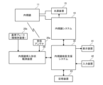
- FIG. 1 is a diagram showing the overall system configuration related to colonoscopy according to an embodiment.
- an endoscope system 10 an endoscope 11, a light source device 15, an endoscope position detection unit (UPD) 20, an endoscope examination support system 30, a display device 41, An input device 42 and a storage device 43 are used.
- the endoscope 11 according to the present embodiment is a colonoscope inserted into the large intestine of a subject (patient).
- the endoscope 11 includes a lens and a solid-state image sensor (for example, a CMOS image sensor, a CCD image sensor, or a CMD image sensor).
- the solid-state image sensor converts the light focused by the lens into an electrical signal, and outputs it to the endoscope system 10 as an endoscopic image (electrical signal).
- Endoscope 11 includes a forceps channel. An operator (doctor) can perform various treatments during an endoscopy by passing a treatment tool through the forceps channel.
- the light source device 15 includes a light source such as a xenon lamp, and supplies observation light (white light, narrowband light, fluorescence, near-infrared light, etc.) to the tip of the endoscope 11.
- the light source device 15 also has a built-in pump that sends water and air to the endoscope 11.
- the endoscope system 10 controls the light source device 15 and processes endoscopic images input from the endoscope 11.
- the endoscope system 10 can perform, for example, Narrow Band Imaging (NBI), Red Dichromatic Imaging (RDI), Texture and Color Enhancement Imaging (TXI), and Extended Depth of Field (TXI). It is equipped with functions such as EDOF (Extended Depth of Field).
- Narrow Band Imaging Narrow Band Imaging
- RDI Red Dichromatic Imaging
- TXI Texture and Color Enhancement Imaging
- TXI Texture and Color Enhancement Imaging
- TXI Extended Depth of Field
- EDOF Extended Depth of Field
- Narrowband light observation uses specific wavelengths of violet (415 nm) and green (540 nm), which are strongly absorbed by hemoglobin in the blood, to highlight capillaries and microstructures in the surface layer of the mucous membrane. A mirror image can be obtained.
- violet 415 nm
- green 540 nm
- Structural color enhancement generates an endoscopic image in which the three elements of the mucosal surface, ⁇ structure,'' ⁇ tone,'' and ⁇ brightness,'' are optimized under normal light observation.
- the endoscope system 10 uses an endoscopic image obtained by processing an endoscopic image input from the endoscope 11, or an endoscopic image input from the endoscope 11 as it is, to the endoscopy support system 30. Output to.
- the endoscope insertion shape observation device 20 is a device for observing the three-dimensional shape of the endoscope 11 inserted into the lumen of the subject.
- a receiving antenna 20a is connected to the endoscope insertion shape observation device 20.
- the receiving antenna 20a is an antenna for detecting a magnetic field generated by a plurality of magnetic coils built into the endoscope 11.
- FIG. 2 is a diagram showing an example of the endoscope 11 used in this embodiment.
- the endoscope 11 has an elongated tubular insertion section 11a made of a flexible member, and an operation section 11e connected to the proximal end of the insertion section 11a.
- the insertion portion 11a has, from the distal end side to the proximal end side, a hard distal end portion 11b, a curved portion 11c, and a flexible tube portion 11d.
- the proximal end of the rigid tip portion 11b is connected to the distal end of the curved portion 11c, and the proximal end of the curved portion 11c is connected to the proximal end of the flexible tube portion 11d.
- the operating part 11e has a main body part 11f from which a flexible tube part 11d extends, and a grip part 11g connected to the base end of the main body part 11f.
- the grip portion 11g is gripped by the operator.
- a universal cord including an imaging electric cable, a light guide, etc. extending from inside the insertion section 11a extends from the operation section 11e, and is connected to the endoscope system 10 and the light source device 15.
- the rigid tip portion 11b is the tip of the insertion portion 11a and is also the tip of the endoscope 11.
- a solid-state image sensor, an illumination optical system, an observation optical system, etc. are built into the rigid tip portion 11b. Illumination light emitted from the light source device 15 is propagated along the light guide to the distal end surface of the rigid distal end portion 11b, and is irradiated from the distal end surface of the rigid distal end portion 11b toward an observation target within the lumen.
- the curved portion 11c is constructed by connecting node rings along the longitudinal axis direction of the insertion portion 11a.
- the curved portion 11c is curved in a desired direction in response to the operator's operation input to the operating portion 11e, and the position and orientation of the rigid distal end portion 11b are changed in accordance with the curvature.
- the flexible tube portion 11d is a tubular member extending from the main body portion 11f of the operating portion 11e, has desired flexibility, and is bent by external force. The operator inserts the insertion section 11a into the large intestine of the subject while bending the bending section 11c and twisting the flexible tube section 11d.
- a plurality of magnetic coils 12 are arranged inside the insertion portion 11a at predetermined intervals (for example, 10 cm intervals) along the longitudinal direction. Each magnetic coil 12 generates a magnetic field when supplied with current.
- the plurality of magnetic coils 12 function as a position sensor for detecting each position of the insertion portion 11a.
- the receiving antenna 20a receives magnetic fields transmitted from a plurality of magnetic coils 12 built into the insertion section 11a of the endoscope 11, and outputs the magnetic fields to the endoscope insertion shape observation device 20.
- the endoscope insertion shape observation device 20 applies the magnetic field strength of each of the plurality of magnetic coils 12 received by the receiving antenna 20a to a predetermined position detection algorithm, and determines the three-dimensional position of each of the plurality of magnetic coils 12. Estimate.
- the endoscope insertion shape observation device 20 generates a three-dimensional endoscope shape of the insertion portion 11a of the endoscope 11 by performing curve interpolation on the estimated three-dimensional positions of the plurality of magnetic coils 12.
- the reference plate 20b is attached to the subject (for example, the abdomen of the subject).
- a body position sensor for detecting the body position of the subject is arranged on the reference plate 20b.
- a three-axis acceleration sensor or a gyro sensor can be used as the body position sensor.
- the reference plate 20b is connected to the endoscope insertion shape observation device 20 by a cable, and the reference plate 20b internally collects three-dimensional posture information indicating the posture of the reference plate 20b (that is, the posture of the subject). It is output to the mirror insertion shape observation device 20.
- a plurality of magnetic coils similar to the plurality of magnetic coils 12 built into the insertion section 11a of the endoscope 11 may be used as the body position sensor disposed on the reference plate 20b.
- the receiving antenna 20a receives the magnetic field transmitted from the plurality of magnetic coils arranged on the reference plate 20b, and outputs it to the endoscope insertion shape observation device 20.
- the endoscope insertion shape observation device 20 applies the magnetic field strength of each of the plurality of magnetic coils received by the receiving antenna 20a to a predetermined attitude detection algorithm to determine the attitude of the reference plate 20b (i.e., the attitude of the subject). ) is generated.
- the endoscope insertion shape observation device 20 changes the generated three-dimensional endoscope shape to follow changes in the three-dimensional posture information. Specifically, the endoscope insertion shape observation device 20 changes the three-dimensional endoscope shape so as to cancel out the change in the three-dimensional posture information. As a result, even if the subject's body position is changed during endoscopy, the endoscope shape is always maintained from a specific viewpoint (for example, the perspective of viewing the subject's abdomen vertically from the front side of the abdomen). can be recognized.
- a specific viewpoint for example, the perspective of viewing the subject's abdomen vertically from the front side of the abdomen.
- the endoscope insertion shape observation device 20 measures the insertion length indicating the length of the portion of the endoscope 11 inserted into the large intestine, and the elapsed time since the endoscope 11 was inserted into the large intestine (hereinafter referred to as insertion time). ) can be obtained.
- the endoscope insertion shape observation device 20 measures the insertion length using the position of the timing at which the operator inputs the examination start operation into the input device 42 as a reference point, and measures the insertion time using the timing as the starting point.
- the endoscope insertion shape observation device 20 estimates the position of the anus from the generated three-dimensional endoscope shape and the difference in magnetic field strength between the magnetic coil inside the body and the magnetic field coil outside the body, and the estimated anus position.
- the position may be used as the base point of the insertion length.
- an encoder may be installed near the anus of the subject.
- the endoscope insertion shape observation device 20 detects the insertion length based on the anus position based on the signal from the encoder.
- the endoscope insertion shape observation device 20 adds the insertion length and insertion time to the 3D endoscope shape after body position correction based on the 3D posture information, and outputs the result to the endoscopy support system 30.
- the endoscopy support system 30 performs endoscopy based on the endoscope image input from the endoscope system 10 and the endoscope shape input from the endoscope insertion shape observation device 20. Generate support information and present it to the operator. Furthermore, the endoscopy support system 30 uses the endoscope image inputted from the endoscope system 10 and the endoscope shape inputted from the endoscope insertion shape observation device 20 to Inspection history information is generated and recorded in the storage device 43.
- the display device 41 includes a liquid crystal monitor or an organic EL monitor, and displays images input from the endoscopy support system 30.
- the input device 42 includes a mouse, a keyboard, a touch panel, etc., and outputs operation information input by a surgeon or the like to the endoscopy support system 30.
- the storage device 43 includes a storage medium such as an HDD or an SSD, and stores endoscopy history information generated by the endoscopy support system 30.
- the storage device 43 may be a dedicated storage device attached to the endoscope system 10, a database in an in-hospital server connected via an in-hospital network, or a database in a cloud server. It may be.
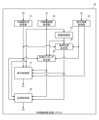
- FIG. 3 shows a configuration example of an endoscopy support system 30 according to an embodiment.
- the endoscopy support system 30 may be constructed with a processing device dedicated to endoscopy support, or may be constructed with a general-purpose server (which may be a cloud server). Furthermore, the endoscopy support system 30 may be constructed with any combination of a processing device dedicated to endoscopy support, a general-purpose server (which may be a cloud server), and a dedicated image diagnostic device. . Further, the endoscopy support system 30 may be constructed integrally with the endoscope system 10.
- the endoscope shape acquisition unit 31 acquires the endoscope shape from the endoscope insertion shape observation device 20.
- the endoscope shape also includes information on insertion length and insertion time.
- the endoscopic image acquisition unit 32 acquires endoscopic images from the endoscope system 10.
- the image recognition unit 34 has a plurality of machine learning models for detecting the site of the large intestine, the state within the large intestine lumen, and lesions from the endoscopic image.
- a plurality of machine learning models are generated by machine learning using a large number of endoscopic images each annotated with various parts, various states, and various lesions as a supervised data set.
- the annotation is provided by an annotator with specialized knowledge such as a doctor.
- CNN, RNN, LSTM, etc. which are types of deep learning, can be used.
- the parts of the large intestine can be broadly classified into the rectum, sigmoid colon, descending colon, transverse colon, ascending colon, and cecum, in order from the anal side.
- the image recognition unit 34 can input the endoscopic image to the region learning model and detect the region of the large intestine from the endoscopic image. At this time, the image recognition unit 34 may identify the region based on the detection results of a plurality of chronologically consecutive endoscopic images. For example, when the same region is detected in a set number or more of consecutive endoscopic images of 30 frames or 60 frames, the image recognition unit 34 specifies the region as an officially detected region.
- the image recognition unit 34 may identify the region by considering the anteroposterior relationship of the detected region or the shape of the endoscope acquired from the endoscope insertion shape observation device 20.
- the image recognition unit 34 identifies, for example, whether the direction of movement of the endoscope 11 is the insertion direction (anus ⁇ cecum) or the removal direction (cecum ⁇ anus). In the case of the insertion direction, the image recognition unit 34 switches the detection site from the descending colon to the transverse colon when the left colon flexure is detected, and switches the detection site from the transverse colon to the ascending colon when the right colon flexure is detected. Switch.
- the image recognition unit 34 switches the detection site from the ascending colon to the transverse colon when the right colonic flexure is detected, and switches the detection site from the transverse colon to the descending colon when the left colonic flexure is detected. Switch.
- the image recognition unit 34 takes into account the three-dimensional position of the rigid tip portion 11b (hereinafter referred to as the endoscope tip portion) based on the endoscope shape obtained from the endoscope insertion shape observation device 20.
- the accuracy of part detection may be improved.
- the image recognition unit 34 discards the detection result based on image recognition when the position of the endoscope tip estimated from the shape of the endoscope and the position of the detected part based on image recognition are inconsistent.
- the image recognition unit 34 can also input the endoscopic image into the intraluminal state learning model and determine the intraluminal state from the endoscopic image.
- the image recognition unit 34 can detect, for example, the presence or absence of folds of a predetermined height or more, and the presence or absence of diverticula.
- the image recognition unit 34 can also input endoscopic images to the lesion learning model and detect lesion candidates from the endoscopic images.
- the image recognition unit 34 may check the image quality of the endoscopic image prior to image recognition of the detection target.
- the image recognition unit 34 excludes endoscopic images that are determined to have poor image quality (for example, blur, out of focus, abnormal brightness (for example, halation)) from image recognition targets of detection targets.
- the reference position determination unit 35 determines the shape of the endoscope to be set as the reference position from the shape of the endoscope that is continuously acquired from the endoscope insertion shape observation device 20.
- the reference position is determined to be the position when the deepest part is reached during colonoscopy. Usually, the deepest part of the colonoscopy is the cecum. Note that depending on the operator, the endoscope 11 may be inserted up to the ileum. Furthermore, depending on the subject, the endoscope 11 may not be able to be inserted into the cecum, and the ascending colon may be the deepest part of the colonoscopy.
- the reference position determination unit 35 determines the position when the insertion length obtained from the endoscope insertion shape observation device 20 is the longest as the position when the deepest part is reached. Further, the reference position determination unit 35 may determine the imaging position of the endoscopic image in which the cecum is detected by the image recognition unit 34 as the position when the deepest part is reached. Further, the reference position determination unit 35 may determine the position at the timing when the operator inputs the insertion completion operation into the input device 42 as the position when the deepest part is reached.
- the recording timing determination unit 36 determines the recording timing of the endoscopic image and the shape of the endoscope.
- the recording timing determination unit 36 determines, for example, the timing at which the operator presses the photographing button (release button) of the operation unit 11e as the recording timing. Note that if a microphone is installed in the operator's throat or the like, the operator can also instruct the recording timing by voice. Furthermore, the recording timing determining unit 36 may determine the recording timing to be the timing at which the endoscopic image in which the lesion candidate is detected is captured by the image recognizing unit 34 .
- the recording timing determination unit 36 may automatically determine the recording timing based on a predetermined rule. Automatic recording of endoscopic images and endoscopic shapes is utilized to generate examination digests. Generally, in colonoscopy, the endoscope 11 is inserted into the cecum and then removed toward the anus while observation and treatment are performed. For example, the recording timing determining unit 36 may set the recording timing every time the insertion length increases by a predetermined interval (for example, several cm). Further, the recording timing determining unit 36 may set the recording timing every time the removal time elapses for a predetermined period of time.
- a predetermined interval for example, several cm
- the recording timing determining unit 36 may change the frequency of automatic recording depending on the site or intraluminal state detected by the image recognition unit 34. For example, the recording timing determining unit 36 increases the frequency of automatic recording while passing through a region where lesions are likely to occur. Furthermore, the recording timing determining unit 36 increases the frequency of automatic recording while passing through a location where the intraluminal condition is poor. Note that the areas to be automatically recorded may be set in advance based on the past history and epidemiological knowledge of the subject.
- the recording timing determining unit 36 may determine as the recording timing at least one or all of the timing based on the operator's operation, the timing based on the detection of a lesion candidate by the image recognition unit 34, and the timing based on automatic settings. good.
- the display control unit 37 When displaying examination information including endoscopic images, the display control unit 37 simultaneously displays two endoscope shapes: the endoscope shape when reaching the deepest part and the endoscope shape at a specific recording timing. 41. Note that the display control unit 37 may display the two endoscope shapes when a predetermined operation is input to the input device 42. The display control unit 37 may display the two endoscope shapes in one graph, or may display them side by side in two graphs.
- the display control unit 37 can display the two endoscope shapes in real time during the examination.
- the display control unit 37 superimposes a mark surrounding the lesion candidate on the endoscopic image in which the lesion candidate is detected. This makes it possible to reduce the risk of missing a lesion. Note that an alert sound may be output from a speaker.
- the subject may change his or her body position or move slightly on his or her own in accordance with the operator's instructions.
- the body position change is performed to facilitate insertion of the endoscope 11 and observation. Therefore, the position and orientation of the endoscope may deviate from the coordinate space based on the position and orientation of the examination room or examination table (bed).
- the reference plate 20b is attached to the subject, the position and orientation of the subject are detected, and the position and orientation of the endoscope shape are corrected based on the detection results.
- the position and orientation of the endoscope shape can be corrected by matching the colon lumen arrangement model with the endoscope shape. This is particularly effective during removal because the shape of the insertion portion 11a generally matches the arrangement of the large intestine lumen. This correction may be performed by the endoscope insertion shape observation device 20 or may be performed by the endoscopy support system 30.
- the recording control unit 38 stores the examination information including the endoscopic images acquired during the examination in the storage device 43 by associating the shape of the endoscope when reaching the deepest part with the shape of the endoscope at at least one recording timing. Record. Since the shape of the endoscope when reaching the deepest part is common in one case, it is only necessary to record it in association with the case. Note that the format of the endoscope shape data to be recorded does not matter. For example, it may be a mathematical formula for calculating the shape, point cloud data for indicating the shape, or image data viewed from one or more directions.
- the examination information recorded in the storage device 43 is read out to the endoscopy support system 30.
- the display control unit 37 displays two types of endoscope shapes on the display device 41: the endoscope shape at the time of reaching the deepest point associated with the examination information, and the endoscope shape at at least one recording timing.
- the test information may be displayed on the monitor of another PC after appropriately selecting the test information, changing the format, or transferring the test information to another database.
- two types of endoscope shapes are simultaneously displayed on the monitor: the endoscope shape when reaching the deepest part and the endoscope shape at at least one recording timing.
- the display control unit 37 and the recording control unit 38 respectively display the first endoscope shape when the endoscope tip is located at a predetermined position and the shape of the endoscope in endoscopy. It is possible to acquire an endoscopic image taken during the examination and the shape of the second endoscope when the endoscopic image was taken. This allows the endoscopic image to be divided into the shape of the second endoscope when the endoscopic image was taken and the shape of the first endoscope when the endoscope tip is located at a predetermined location. It becomes possible to present the shape and the shape at the same time.
- the first endoscope shape and the second endoscope shape are different shapes from each other.
- the predetermined region may be the deepest region during endoscopy.
- the shape of the endoscope when the distal end portion of the endoscope is located at the deepest point can be determined to be the first shape of the endoscope.
- the predetermined site may be the cecum. In this case, it is possible to determine the shape of the first endoscope when the deepest part during endoscopy is the cecum.
- the insertion portion 11a of the endoscope 11 is inserted into the tortuous intestinal tract of the large intestine.
- the insertion shape of the endoscope 11 may change even in the same patient due to differences in doctors or insertion techniques, or due to differences in the insertion shape of the endoscope 11 for each examination due to changes in the position of the unfixed intestinal section in the body, expansion and contraction, etc. can change.
- the internal arrangement of parts fixed to the patient's body such as the ascending colon and descending colon, does not change significantly.
- the end of the large intestine, the caecum is located at the end of these fixed parts, and its position within the body does not change much.
- the caecum is the deepest part of the large intestine, and is the area that doctors aim to reach during colonoscopy.
- the endoscope 11 may be inserted as far as the ileum, which is the end of the small intestine, but the cecum can serve as a relatively stable reference point during examinations because it is located at the end of the ascending colon, which is a fixed part. This is one of the parts.
- the deepest part is one of the sites that can serve as a reference point.
- the endoscope 11 when the endoscope 11 is removed from the deepest part, for example, the cecum, even if the intestinal tract is inserted in a bent manner, the bent portion is lengthened and the degree of bending is reduced. As a result, the intestinal tract at the time of removal takes on a shape with less curvature, based on its original arrangement. It is thought that the shape and arrangement of the intestinal tract will become more stable than at the time of insertion. At this time, the tip of the insertion portion 11a of the endoscope 11 is considered to take a route or draw a trajectory with less variation than when inserted.
- the route or trajectory is approximately determined by the following.
- the reference position determination unit 35 determines that the endoscope tip is located at a predetermined location based on at least one of the endoscopic image, the shape of the endoscope, and the insertion length of the endoscope.
- the display control unit 37 and the recording control unit 38 each acquire the endoscope shape when the endoscope tip is located at a predetermined location as the first endoscope shape. In this case, the first endoscope shape can be automatically acquired.
- the display control unit 37 and the recording control unit 38 each define the endoscope shape at the timing when the reference position determination unit 35 acquires the endoscope insertion completion signal based on the operator's operation as the first endoscope shape. You may also obtain it as In this case, it is possible to obtain the first endoscope shape that matches the operator's intention.
- the recording control unit 38 records the first endoscope shape, the photographed endoscopic image, and the second endoscope shape corresponding to the endoscope image in the storage device 43 in association with each other. be able to. According to this, after an examination, the endoscopic image is divided into the second endoscope shape when the endoscopic image was taken and the second endoscope shape when the endoscope tip is located at a predetermined position. It becomes possible to present the endoscope shape of 1 at the same time.
- the display control unit 37 can display the first endoscope shape and the second endoscope shape on the display device 41 at the same time. According to this, the operator or doctor can intuitively grasp the relative position of the second endoscope shape when the endoscopic image is taken. At this time, the display control unit 37 can display the first endoscope shape and the second endoscope shape on one graph. According to this, the operator or doctor can more accurately grasp the relative position of the second endoscope shape when the endoscopic image is taken. Furthermore, the display control unit 37 can simultaneously display the first endoscope shape, the second endoscope shape, and the endoscopic image corresponding to the second endoscope shape on the display device 41. can. According to this, the operator or doctor can simultaneously grasp the endoscopic image and the relative position of the second endoscope shape when the endoscopic image was taken.
- the placement of the tip of the first endoscope shape and the tip of the second endoscope shape on the intestinal tract is displayed with relatively high reproducibility. Therefore, based on the first endoscope shape placed deeper and its tip position, the tip of the second endoscope shape is changed from the second endoscope shape at the position where it is removed from that position. The position and arrangement within the intestinal tract can be confirmed with relatively good reproducibility. These results can be checked during and after the test. Therefore, it becomes position specifying information when recording the position of a lesion, etc. during an examination, and can serve as guide information with good reproducibility when approaching the same lesion, etc. during subsequent examinations or treatments. In particular, by using images taken when the endoscope is in the second shape, it becomes easier to identify the location of the lesion, approach it again, and more accurately determine the location. Become.
- the second endoscope shape is obtained when inserting the endoscope 11, it is possible to record it by comparing it with the shape when it reaches the deepest part or the cecum, as a record when inserting into a difficult-to-insert site. It is useful as a record of individual examinations and patients in that it can be confirmed along with the tip position, insertion shape, and events at that position.
- FIG. 4 is a diagram showing example 1 of the screen displayed on the display device 41.
- the following example screen assumes a screen example when a doctor confirms test information after an examination, but a similar screen display is also possible during the examination.
- a similar screen display is also possible during the examination.
- the endoscope shape B1 at the time of reaching the cecum and the plurality of endoscope shapes B2 to B8 at the time of imaging are displayed simultaneously on the graph placed in the center.
- the display control unit 37 aligns and displays a specific portion of the endoscope shape B1 and specific portions of the plurality of endoscope shapes B2 to B8.
- the specific portion may be a site corresponding to the insertion port of the subject into which the endoscope 11 is inserted (in the case of colonoscopy, the anus).
- the plurality of endoscope shapes B2 to B8 (second endoscope shape) at the time of imaging are It can be placed in a position that matches the actual situation.
- Marks C1 to C8 indicating imaging positions are added to the distal ends of the endoscope shape B1 when reaching the cecum and the plurality of endoscope shapes B2 to B8 during imaging, respectively.
- a plurality of endoscopic images A1-A8 are displayed surrounding a graph placed in the center.
- the endoscopic image A1 on the lower left is an endoscopic image when the cecum is reached, and a plurality of endoscopic images A2 to A8 are arranged clockwise in order of the removal direction.
- the insertion length and insertion time are displayed in each of the endoscopic images A1 to A8.
- the display control unit 37 acquires the plurality of endoscopic images A2-A8 and the plurality of endoscopic shapes B2-B8 corresponding to the plurality of endoscopic images A2-A8, respectively, and displays the plurality of endoscopic images A2. -A8 and the plurality of endoscope shapes B2-B8 are displayed on the display device 41 at the same time as the endoscope shape B1. Displaying a list of multiple endoscope images A2-A8, multiple endoscope shapes B2-B8 (second endoscope shape), and endoscope shape B1 (first endoscope shape). This makes it easier for surgeons and doctors to understand the overall picture of endoscopy.
- the display control unit 37 estimates the change in the position and orientation of the subject from the change in the acquired endoscope shape, and performs the estimation. Based on the results, the endoscope shape B1 and the plurality of endoscope shapes B2-B8 are aligned and faced. The display control unit 37 simultaneously displays the endoscope shape B1 and the plurality of endoscope shapes B2-B8 on the display device 41 after alignment and facing. According to this, the endoscope shape B1 (first endoscope shape) when reaching the cecum and the plurality of endoscope shapes B2 to B8 (second endoscope shape) at the time of imaging are compared to the actual situation. It is possible to continuously display the shape of the endoscope from a specific viewpoint (for example, a viewpoint viewing the abdomen of the subject perpendicularly from the front side of the abdomen) while arranging it in a regular position.
- a specific viewpoint for example, a viewpoint viewing the abdomen of the subject perpendicularly from the front side of the abdomen
- lesion candidates are detected in three endoscopic images A2, A3, and A6.
- Marks D2, D3, and D6 surrounding the respective lesion candidates are superimposed on the three endoscopic images A2, A3, and A6.
- mark C1-C8 indicating the imaging positions of multiple endoscope shapes B1-B8
- endoscope shapes B1, B4- are associated with endoscope images A1, A4-A5, and A7-A8 in which no lesion candidate is detected.
- Marks C1, C4-C5, and C7-C8 indicating the imaging positions of B5 and B7-B8 are displayed as round marks, and the endoscopes are linked to the endoscopic images A2, A3, and A6 in which lesion candidates are detected.
- Marks C2, C3, and C6 indicating the photographing positions of shapes B2, B3, and B6 are displayed as star marks.
- the display control unit 37 displays endoscopic images A2, A3, and A6 in which lesion candidates are detected, and an endoscope shape B2 when the endoscopic images A2, A3, and A6 in which lesion candidates are detected are captured. B3 and B6 are acquired. According to this, it is possible to obtain a highly important endoscopic image using the shape of the endoscope as a display target.
- the display control unit 37 displays the endoscope shapes B2, B3, and B6, and the marks C2, C3, and C6 that indicate that a lesion candidate has been detected and are placed at the distal ends of the endoscope shapes B2, B3, and B6. It is displayed on the display device 41 at the same time. According to this, the operator or doctor can more easily grasp the imaging position of the endoscopic image in which the lesion candidate is detected.
- the shape of the endoscope with the subject in a supine position on the examination table is shown from the ceiling perspective.
- the shape of the endoscope viewed from two or three directions may be displayed, or the shape of the endoscope viewed from an oblique direction may be displayed in a perspective view.
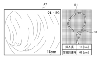
- FIG. 5 is a diagram showing a second example screen displayed on the display device 41.
- Screen example 2 is a screen example that changes when endoscopic image A7 is selected by a user such as a doctor by a click operation or a touch operation in screen example 1 shown in FIG. 4.
- the endoscopic image A7 that has been noticed by the user is displayed, and on the right side of the screen, the endoscope shape B7 when capturing the endoscopic image A7 and the endoscope shape B1 when reaching the cecum are displayed.
- a single graph is displayed in which both are plotted at the same time.
- the insertion length (18 [cm]) when the endoscopic image A7 was captured and the insertion length (68 [cm]) when reaching the cecum are displayed below the graph. Note that the graph and insertion length table on the right side may be displayed only when the user performs a predetermined operation on the endoscopic image A7 in order to simplify the screen display.
- the display control unit 37 displays an endoscopic image A7 selected by the user from the plurality of endoscopic images A2-A8 and an endoscope shape B7 corresponding to the selected endoscopic image A7. It is displayed on the display device 41 at the same time as the shape B1. According to this, it is possible to generate a screen that focuses on the information of the endoscopic image that the user is interested in.
- the display control unit 37 displays the insertion length corresponding to the endoscope shape B1 and the insertion length corresponding to the endoscope shape B7 on the display device 4 at the same time as the endoscope shape B1 and the endoscope shape B7. may be displayed. By displaying the insertion length at the same time, the amount of information presented to the user can be increased.
- the display control unit 37 displays the insertion time corresponding to the endoscope shape B1 and the insertion time corresponding to the endoscope shape B7 on the display device 41 at the same time as the endoscope shape B1 and the endoscope shape B7. You may. By displaying the insertion time at the same time, the amount of information presented to the user can be increased.
- FIG. 6 is a diagram showing a third example screen displayed on the display device 41.
- screen example 3 only the endoscope shape B11 when reaching the cecum is displayed on the three-dimensional graph placed in the center.
- a plurality of endoscopic images A11 to A21 are displayed surrounding a graph placed in the center.
- the plurality of endoscopic images A11-A21 may be thumbnail images.
- the endoscopic image A11 on the lower left is an endoscopic image when the cecum is reached, and a plurality of endoscopic images A12 to A21 are arranged clockwise in the order of the removal direction.
- Marks C11-C21 are added to the endoscope shape B11 when the endoscope reaches the cecum, indicating the respective imaging positions of the plurality of endoscopic images A11-A21.
- FIG. 7 is a diagram showing example 4 of the screen displayed on the display device 41.
- Screen example 4 is a screen example that changes when the user selects endoscopic image A18 in screen example 3 shown in FIG.
- the endoscopic image A18 that has been noticed by the user is displayed, and on the right side of the screen, the endoscope shape B18 when capturing the endoscopic image A18 and the endoscope shape B11 when reaching the cecum are displayed.
- a single graph is displayed in which both are plotted at the same time.
- the insertion length (23 [cm]) at the time of capturing the endoscopic image A18 is displayed below the graph. Note that the screen example shown in FIG. 6 and the screen example shown in FIG. 7 may be displayed on one screen.
- the display control unit 37 shows the endoscope shape B11, the plurality of endoscopic images A11-A21, and the shooting positions of each of the plurality of endoscopic images A11-A21 arranged on the endoscope shape B11.
- a first display mode in which marks C11 to C21 are displayed on the display device 41, an endoscope image A18 selected by the user, an endoscope shape B18 corresponding to the selected endoscope image A18, and an endoscope shape B18 corresponding to the selected endoscope image A18. It is possible to switch between a second display mode in which the endoscope shape B11 and the endoscope shape B11 are simultaneously displayed on the display device 41. According to this, visibility or operability for the user can be improved.
- FIG. 8 is a diagram showing screen example 5 displayed on the display device 41.
- an insertion length straight line E1 generated by straightening the endoscope shape B11 when reaching the cecum shown in FIG. are displayed in parallel with the insertion long line E1.
- the plurality of endoscopic images A11-A21 may be thumbnail images.
- the leftmost endoscopic image A11 is an endoscopic image when the cecum is reached, and a plurality of endoscopic images A12 to A21 are arranged toward the right in the order of the removal direction.
- Marks C11-C21 are added on the insertion length straight line E1 to indicate the respective imaging positions of the plurality of endoscopic images A11-A21.
- the display control unit 37 displays the endoscope shape B11, the plurality of endoscopic images A11-A21, and the plurality of endoscopic images arranged on the insertion length straight line E1 generated by linearizing the endoscope shape B11. It is possible to switch between a third display mode in which marks C11-C21 indicating the shooting positions of A11-A21 are displayed on the display device 41, and the second display mode. According to this, visibility or operability for the user can be improved.
- FIG. 9 is a diagram showing screen example 6 displayed on the display device 41.
- an insertion time straight line E2 generated by linearizing the endoscope shape B11 when reaching the cecum shown in FIG. 6 is displayed, and above the insertion time straight line E2, a plurality of endoscopic images A11-A21 are displayed. are displayed in parallel with the insertion time straight line E2.
- the plurality of endoscopic images A11-A21 may be thumbnail images.
- the leftmost endoscopic image A11 is an endoscopic image when the cecum is reached, and a plurality of endoscopic images A12 to A21 are arranged toward the right in the order of the removal direction.
- Marks C11-C21 are added on the insertion time straight line E2 to indicate the imaging timing of each of the plurality of endoscopic images A11-A21.
- the insertion time when the cecum is reached is 4:26 after the start of insertion, and the insertion time is counted up from there until the removal is completed.
- the screen changes to the example screen shown in FIG. 7.
- the display control unit 37 displays the endoscope shape B11, the plurality of endoscopic images A11-A21, and the plurality of endoscopic images arranged on the insertion time straight line E2 generated by linearizing the endoscope shape B11. It is possible to switch between a fourth display mode in which marks C11-C21 indicating the respective photographing timings of A11-A21 are displayed on the display device 41, and the second display mode. According to this, visibility or operability for the user can be improved.
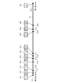
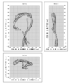
- FIGS. 10(a) to 10(c) are diagrams showing examples in which a plurality of endoscope shapes are displayed as trigonometric projection views from three directions.
- the y direction is the longitudinal direction
- the x direction is the lateral direction
- the z direction is the thickness direction of the subject in the supine position.
- FIG. 10(a) shows an example in which a plurality of endoscope shapes are plotted on xy coordinates.
- the left side of the x-axis is the direction of the right flank
- the right side of the x-axis is the direction of the left flank
- the upper side of the y-axis is the direction of the chest
- the lower side of the y-axis is the direction of the foot.
- FIG. 10(b) shows an example in which a plurality of endoscope shapes are plotted on the zy coordinate.
- the left side of the z-axis is the direction of the abdomen
- the right side of the z-axis is the direction of the back
- the upper side of the y-axis is the direction of the chest
- the lower side of the y-axis is the direction of the feet.
- FIG. 10(c) shows an example in which a plurality of endoscope shapes are plotted on xz coordinates.
- the left side of the x-axis is the direction of the right flank
- the right side of the x-axis is the direction of the left flank
- the upper side of the z-axis is the direction of the abdomen
- the lower side of the z-axis is the direction of the back.
- FIG. 11 is a diagram showing an example of a bird's-eye perspective view of the three-dimensional endoscope shape B31 when the endoscope reaches the cecum.
- a coordinate system is used in which the origin is the position corresponding to the anus, which is the starting point of insertion into the body.
- the coordinate system has memory for actual dimensions.
- the direction and scale of the viewpoint can be appropriately changed and set to the direction and size desired by the operator to confirm the three-dimensional endoscope shape B31.
- a plurality of endoscope shapes at the time of imaging as shown in FIG. 4 may also be displayed simultaneously on the same three-dimensional graph.
- the coordinate system and dimensions may be displayed in any manner. For example, the coordinate system may not be displayed, the origin may not be the anus position, the dimensions may not be displayed, or only the scale may be displayed.
- FIG. 13 is a flowchart illustrating an example of the operation of the endoscopy support system 30 according to the embodiment when confirming examination information.
- the display control unit 37 displays the shape of the endoscope at the time of reaching the deepest point, the plurality of endoscopic images taken by the operator, and the plurality of endoscopic images corresponding to the respective shooting timings, which are recorded in association with the storage device 43.
- the endoscope shape is read from the storage device 43 (S20).
- the display control unit 37 displays a digest of the plurality of read endoscopic images on the display device 41 (S21).
- the display control unit 37 displays the endoscopic image selected by the user, the shape of the endoscope corresponding to the endoscopic image, and the shape of the endoscope when reaching the deepest part on the display device 41 (S22). .
- the lesion or lesion candidate can be re-accessed with the endoscope 11. It becomes easier to do. The operator can more accurately grasp the position within the colon lumen where a lesion or lesion candidate exists, and re-access becomes easier. Further, by employing the various display forms described above, visibility or operability for the user can be improved.
- a plurality of shape sensors may be built into the endoscope 11 to estimate the shape of the endoscope.
- the shape sensor may be, for example, a fiber sensor that detects the bent shape from the curvature of a specific location using an optical fiber.
- the fiber sensor has, for example, an optical fiber arranged along the longitudinal direction of the insertion section 11a, and the optical fiber is provided with a plurality of photodetectors along the longitudinal direction. Detection light is supplied from the detection light emitting device to the optical fiber, and the shape of the endoscope is estimated based on changes in the amount of light detected by each photodetector while the detection light is propagating through the optical fiber.
- the present disclosure can be used for colonoscopy.
Abstract
A display control unit 37 and a recording control unit 38 each acquire the following during an endoscopic examination: a first endoscope shape of when an endoscope distal end is located at a prescribed position; an endoscopy image captured during the endoscopy examination; and a second endoscope shape of when the endoscopy image was captured. The recording control unit 38 may also record the first endoscope shape, the endoscopy image, and the second endoscope shape in a storage device 43. The display control unit 37 may display the first endoscope shape and the second endoscope shape simultaneously on a display device 41.
Description
本開示は、内視鏡検査において術者を支援するための内視鏡検査支援システム、内視鏡検査支援方法および記憶媒体に関する。
The present disclosure relates to an endoscopy support system, an endoscopy support method, and a storage medium for supporting an operator in an endoscopy.
大腸内視鏡検査では、後日に実施する処置や処置後の経過観察をしやすくするために、病変(例えば、ポリープや癌)が確認された際は、確認された病変がどこにあるかを記録することが一般的である。これに関連して、大腸内視鏡検査時に、AIが検出した病変を、大腸模式図の対応する箇所にマーキングする手法が提案されている(例えば、特許文献1参照)。
During colonoscopy, when a lesion (e.g., polyp or cancer) is identified, the location of the identified lesion is recorded to facilitate subsequent procedures and post-procedure follow-up. It is common to do so. In connection with this, a method has been proposed in which lesions detected by AI are marked at corresponding locations on a schematic diagram of the large intestine during colonoscopy (for example, see Patent Document 1).
大腸は変形しやすいため、上記手法で病変の位置を記録した場合でも、後日に内視鏡を再挿入した際、当該病変の位置を特定することが困難なケースがある。
Because the large intestine is easily deformed, even if the location of a lesion is recorded using the above method, it may be difficult to pinpoint the location of the lesion when the endoscope is reinserted at a later date.
本開示はこうした状況に鑑みなされたものであり、その目的は、病変または病変候補へ内視鏡で再アクセスすることを容易にする技術を提供することにある。
The present disclosure has been made in view of these circumstances, and its purpose is to provide a technique that facilitates re-accessing a lesion or lesion candidate with an endoscope.
上記課題を解決するために、本開示のある態様の内視鏡検査支援システムは、ハードウェアを有する1つ以上のプロセッサを備える。プロセッサは、内視鏡検査において、内視鏡先端部が所定の部位に位置しているときの第1の内視鏡形状と、内視鏡検査において撮影された内視鏡画像と、内視鏡画像が撮影されたときの第2の内視鏡形状とを取得する。
In order to solve the above problems, an endoscopy support system according to an aspect of the present disclosure includes one or more processors having hardware. During an endoscopy, the processor determines a first endoscope shape when the endoscope tip is located at a predetermined location, an endoscopic image taken during the endoscopy, and an endoscope image taken during the endoscopy. and the second endoscope shape when the mirror image was taken.
本開示の別の態様は、内視鏡検査支援方法である。この方法は、内視鏡検査において、内視鏡先端部が所定の部位に位置しているときの第1の内視鏡形状と、内視鏡検査において撮影された内視鏡画像と、内視鏡画像が撮影されたときの第2の内視鏡形状とを取得する。
Another aspect of the present disclosure is an endoscopy support method. This method uses the first endoscope shape when the endoscope tip is located at a predetermined location, the endoscopic image taken during the endoscopy, and the internal and the second endoscope shape when the endoscopic image was taken.
なお、以上の構成要素の任意の組み合わせ、本開示の表現を方法、装置、システム、記録媒体、コンピュータプログラム等の間で変換したものもまた、本開示の態様として有効である。
Note that any combination of the above components and the expressions of the present disclosure converted between methods, devices, systems, recording media, computer programs, etc. are also effective as aspects of the present disclosure.
本実施の形態は大腸内視鏡検査に関する。大腸内視鏡検査では、盲腸まで内視鏡を挿入して、抜去時に病変スクリーニング、病変の精査、病変の処置を実施する。病変が確認された際には、その病変がどこにあるかを記録して、後日に実施する処置や処置後の経過観察をしやすくする。また、精査した結果、病変ではない等の理由で処置しない場合にも、その部分が病変化しないか経過観察を実施することがあり、その部分の位置を病変候補として記録することがある。
This embodiment relates to colonoscopy. In colonoscopy, an endoscope is inserted into the cecum, and upon removal, screening for lesions, examination of the lesions, and treatment of the lesions are performed. When a lesion is confirmed, the location of the lesion is recorded to facilitate subsequent treatment and post-treatment follow-up. Furthermore, even if the area is not treated as a result of careful examination because it is not found to be a lesion, follow-up observation may be performed to see if the area changes to a disease, and the location of the area may be recorded as a lesion candidate.
大腸内視鏡検査の病変スクリーニング後の病理診断で、処置が必要とされた場合等、前の検査で見つかった病変または病変候補へ再アクセスすることが日常的に実施されている。同じ医師が再アクセスする場合もあれば、他の医師が再アクセスする場合もある。また、他の施設で再アクセスされる場合もある。
In cases where treatment is required in pathological diagnosis after lesion screening during colonoscopy, re-accessing lesions or lesion candidates found in previous examinations is routinely performed. The same doctor may access the information again, or another doctor may access the information again. It may also be accessed again at other facilities.
しかしながら、大腸は1~1.5m程度の長さがあり、変形しやすい。特に、挿入時の挿入方法によって、同じ病変までの肛門からの挿入長が大きく変わる。同じ医師が試みても簡単に再アクセスできないこともある。専門性の観点から他施設で再アクセスすることもあるが、他の医師が再アクセスすることは、より難易度が上がる。紹介状に大腸のシェーマ図と、おおよその病変位置が記載されることがあるが、シェーマ図の通りに再アクセスしても病変が見つからないこともしばしばある。したがって、医師や施設間で交換される病変位置に関する情報は参考程度となっている。以上から、病変位置または病変候補位置を再現性良く示すことが求められる。
However, the large intestine is approximately 1 to 1.5 meters long and is easily deformed. In particular, the insertion length from the anus to the same lesion varies greatly depending on the insertion method at the time of insertion. Even if the same doctor tries, re-access may not be possible. Although re-access may be performed at other facilities from a specialist standpoint, it is more difficult for other doctors to re-access the site. A schema diagram of the large intestine and the approximate location of the lesion may be included in the referral letter, but the lesion is often not found even if the schema diagram is re-accessed. Therefore, information regarding lesion locations exchanged between doctors and facilities is only for reference. From the above, it is required to indicate a lesion position or a lesion candidate position with good reproducibility.
図1は、実施の形態に係る大腸内視鏡検査に関連する全体システム構成を示す図である。本実施の形態では、内視鏡システム10、内視鏡11、光源装置15、内視鏡挿入形状観測装置(UPD:Endoscope Position Detecting Unit)20、内視鏡検査支援システム30、表示装置41、入力装置42および記憶装置43が使用される。本実施の形態に係る内視鏡11は、被検体(患者)の大腸に挿入される大腸内視鏡である。
FIG. 1 is a diagram showing the overall system configuration related to colonoscopy according to an embodiment. In this embodiment, an endoscope system 10, an endoscope 11, a light source device 15, an endoscope position detection unit (UPD) 20, an endoscope examination support system 30, a display device 41, An input device 42 and a storage device 43 are used. The endoscope 11 according to the present embodiment is a colonoscope inserted into the large intestine of a subject (patient).
内視鏡11は、レンズおよび固体撮像素子(例えば、CMOSイメージセンサ、CCDイメージセンサまたはCMDイメージセンサ)を含む。固体撮像素子は、レンズで集光した光を電気信号に変換し、内視鏡画像(電気信号)として内視鏡システム10に出力する。内視鏡11は鉗子チャンネルを含む。術者(医師)は鉗子チャンネルに処置具を通すことで、内視鏡検査中に種々の処置を実施することができる。
The endoscope 11 includes a lens and a solid-state image sensor (for example, a CMOS image sensor, a CCD image sensor, or a CMD image sensor). The solid-state image sensor converts the light focused by the lens into an electrical signal, and outputs it to the endoscope system 10 as an endoscopic image (electrical signal). Endoscope 11 includes a forceps channel. An operator (doctor) can perform various treatments during an endoscopy by passing a treatment tool through the forceps channel.
光源装置15はキセノンランプ等の光源を備え、内視鏡11の先端部に観察光(白色光、狭帯域光、蛍光、近赤外光等)を供給する。光源装置15は、内視鏡11に水や空気を送り出すポンプも内蔵している。
The light source device 15 includes a light source such as a xenon lamp, and supplies observation light (white light, narrowband light, fluorescence, near-infrared light, etc.) to the tip of the endoscope 11. The light source device 15 also has a built-in pump that sends water and air to the endoscope 11.
内視鏡システム10は、光源装置15を制御するとともに、内視鏡11から入力される内視鏡画像を処理する。内視鏡システム10は例えば、狭帯域光観察(NBI:Narrow Band Imaging)、赤色光観察(RDI:Red Dichromatic Imaging)、構造色彩強調(TXI:Texture and Color Enhancement Imaging)、被写界深度拡大(EDOF:Extended Depth of Field)等の機能を搭載する。
The endoscope system 10 controls the light source device 15 and processes endoscopic images input from the endoscope 11. The endoscope system 10 can perform, for example, Narrow Band Imaging (NBI), Red Dichromatic Imaging (RDI), Texture and Color Enhancement Imaging (TXI), and Extended Depth of Field (TXI). It is equipped with functions such as EDOF (Extended Depth of Field).
狭帯域光観察では、血液中のヘモグロビンに強く吸収される紫(415nm)と緑(540nm)の特定の波長の光を照射することで、粘膜表層の毛細血管や微細構造が強調された内視鏡画像を取得することができる。赤色光観察では、3色(緑・アンバー・赤)の特定の波長の光を照射することで、深部組織のコントラストが強調された内視鏡画像を取得することができる。構造色彩強調では、通常光観察下での粘膜表面の「構造」・「色調」・「明るさ」の3つの要素が最適化された内視鏡画像が生成される。被写界深度拡大では、近距離と遠距離のそれぞれに焦点が合った2つの画像を合成することで、焦点範囲の広い内視鏡画像を取得することができる。
Narrowband light observation uses specific wavelengths of violet (415 nm) and green (540 nm), which are strongly absorbed by hemoglobin in the blood, to highlight capillaries and microstructures in the surface layer of the mucous membrane. A mirror image can be obtained. In red light observation, by irradiating light of three colors (green, amber, and red) with specific wavelengths, it is possible to obtain endoscopic images with enhanced contrast of deep tissues. Structural color enhancement generates an endoscopic image in which the three elements of the mucosal surface, ``structure,'' ``tone,'' and ``brightness,'' are optimized under normal light observation. In expanding the depth of field, it is possible to obtain an endoscopic image with a wide focal range by combining two images that are focused at near and far distances.
内視鏡システム10は、内視鏡11から入力される内視鏡画像を処理した内視鏡画像、または内視鏡11から入力される内視鏡画像をそのまま、内視鏡検査支援システム30に出力する。
The endoscope system 10 uses an endoscopic image obtained by processing an endoscopic image input from the endoscope 11, or an endoscopic image input from the endoscope 11 as it is, to the endoscopy support system 30. Output to.
内視鏡挿入形状観測装置20は、被検体の管腔内に挿入された内視鏡11の3次元形状を観測するための装置である。内視鏡挿入形状観測装置20には、受信アンテナ20aが接続される。受信アンテナ20aは、内視鏡11に内蔵された複数の磁気コイルが発生させる磁界を検出するためのアンテナである。
The endoscope insertion shape observation device 20 is a device for observing the three-dimensional shape of the endoscope 11 inserted into the lumen of the subject. A receiving antenna 20a is connected to the endoscope insertion shape observation device 20. The receiving antenna 20a is an antenna for detecting a magnetic field generated by a plurality of magnetic coils built into the endoscope 11.
図2は、本実施の形態で使用される内視鏡11の一例を示す図である。内視鏡11は、可撓性部材で構成される細長い管状の挿入部11aと、挿入部11aの基端部と連結された操作部11eを有する。挿入部11aは、先端側から基端側へ向かって、先端硬質部11b、湾曲部11cおよび可撓管部11dを有する。先端硬質部11bの基端部は湾曲部11cの先端部と連結し、湾曲部11cの基端部は可撓管部11dの基端部と連結している。
FIG. 2 is a diagram showing an example of the endoscope 11 used in this embodiment. The endoscope 11 has an elongated tubular insertion section 11a made of a flexible member, and an operation section 11e connected to the proximal end of the insertion section 11a. The insertion portion 11a has, from the distal end side to the proximal end side, a hard distal end portion 11b, a curved portion 11c, and a flexible tube portion 11d. The proximal end of the rigid tip portion 11b is connected to the distal end of the curved portion 11c, and the proximal end of the curved portion 11c is connected to the proximal end of the flexible tube portion 11d.
操作部11eは、可撓管部11dが延出している本体部11fと、本体部11fの基端部と連結している把持部11gを有している。把持部11gは術者によって把持される。操作部11eからは、挿入部11a内から延びた撮像用電気ケーブル、ライトガイド等を含むユニバーサルコードが延びており、内視鏡システム10および光源装置15に接続される。
The operating part 11e has a main body part 11f from which a flexible tube part 11d extends, and a grip part 11g connected to the base end of the main body part 11f. The grip portion 11g is gripped by the operator. A universal cord including an imaging electric cable, a light guide, etc. extending from inside the insertion section 11a extends from the operation section 11e, and is connected to the endoscope system 10 and the light source device 15.
先端硬質部11bは、挿入部11aの先端部であって、かつ内視鏡11の先端部でもある。先端硬質部11bには、固体撮像素子、照明光学系、観察光学系等が内蔵される。光源装置15から出射される照明光が、ライトガイドに沿って、先端硬質部11bの先端面に伝搬され、先端硬質部11bの先端面から管腔内の観察対象に向けて照射される。
The rigid tip portion 11b is the tip of the insertion portion 11a and is also the tip of the endoscope 11. A solid-state image sensor, an illumination optical system, an observation optical system, etc. are built into the rigid tip portion 11b. Illumination light emitted from the light source device 15 is propagated along the light guide to the distal end surface of the rigid distal end portion 11b, and is irradiated from the distal end surface of the rigid distal end portion 11b toward an observation target within the lumen.
湾曲部11cは、節輪が挿入部11aの長手軸方向に沿って連結されることにより構成される。湾曲部11cは、操作部11eに入力される術者の操作に応じて所望の方向に湾曲し、その湾曲に応じて先端硬質部11bの位置および向きが変わる。
The curved portion 11c is constructed by connecting node rings along the longitudinal axis direction of the insertion portion 11a. The curved portion 11c is curved in a desired direction in response to the operator's operation input to the operating portion 11e, and the position and orientation of the rigid distal end portion 11b are changed in accordance with the curvature.
可撓管部11dは、操作部11eの本体部11fから延出した管状部材であり、所望の可撓性を有し、外力によって曲がる。術者は、湾曲部11cを湾曲操作したり可撓管部11dを捻ったりしながら、挿入部11aを被検体の大腸へ挿入していく。
The flexible tube portion 11d is a tubular member extending from the main body portion 11f of the operating portion 11e, has desired flexibility, and is bent by external force. The operator inserts the insertion section 11a into the large intestine of the subject while bending the bending section 11c and twisting the flexible tube section 11d.
挿入部11aの内部に長手方向に沿って、所定の間隔(例えば、10cm間隔)で複数の磁気コイル12が配置される。各磁気コイル12は、電流が供給されると磁界を発生させる。複数の磁気コイル12は、挿入部11aの各位置を検出するための位置センサとして機能する。
A plurality of magnetic coils 12 are arranged inside the insertion portion 11a at predetermined intervals (for example, 10 cm intervals) along the longitudinal direction. Each magnetic coil 12 generates a magnetic field when supplied with current. The plurality of magnetic coils 12 function as a position sensor for detecting each position of the insertion portion 11a.
図1に戻る。受信アンテナ20aは、内視鏡11の挿入部11aに内蔵された複数の磁気コイル12から発信される磁界を受信し、内視鏡挿入形状観測装置20に出力する。内視鏡挿入形状観測装置20は、受信アンテナ20aで受信された複数の磁気コイル12のそれぞれの磁界強度を、所定の位置検出アルゴリズムに適用して、複数の磁気コイル12のそれぞれの3次元位置を推定する。内視鏡挿入形状観測装置20は、推定した複数の磁気コイル12の3次元位置を曲線補間することにより、内視鏡11の挿入部11aの3次元内視鏡形状を生成する。
Return to Figure 1. The receiving antenna 20a receives magnetic fields transmitted from a plurality of magnetic coils 12 built into the insertion section 11a of the endoscope 11, and outputs the magnetic fields to the endoscope insertion shape observation device 20. The endoscope insertion shape observation device 20 applies the magnetic field strength of each of the plurality of magnetic coils 12 received by the receiving antenna 20a to a predetermined position detection algorithm, and determines the three-dimensional position of each of the plurality of magnetic coils 12. Estimate. The endoscope insertion shape observation device 20 generates a three-dimensional endoscope shape of the insertion portion 11a of the endoscope 11 by performing curve interpolation on the estimated three-dimensional positions of the plurality of magnetic coils 12.
基準プレート20bは被検体(例えば、被検体の腹部)に装着される。基準プレート20bには、被検体の体位を検出するための体位センサが配置される。体位センサとして例えば、3軸加速度センサやジャイロセンサを使用することができる。図1では基準プレート20bはケーブルで内視鏡挿入形状観測装置20に接続されており、基準プレート20bは、基準プレート20bの姿勢(即ち、被検体の姿勢)を示す3次元姿勢情報を内視鏡挿入形状観測装置20に出力する。
The reference plate 20b is attached to the subject (for example, the abdomen of the subject). A body position sensor for detecting the body position of the subject is arranged on the reference plate 20b. For example, a three-axis acceleration sensor or a gyro sensor can be used as the body position sensor. In FIG. 1, the reference plate 20b is connected to the endoscope insertion shape observation device 20 by a cable, and the reference plate 20b internally collects three-dimensional posture information indicating the posture of the reference plate 20b (that is, the posture of the subject). It is output to the mirror insertion shape observation device 20.
なお、基準プレート20bに配置される体位センサとして、内視鏡11の挿入部11aに内蔵された複数の磁気コイル12と同様の、複数の磁気コイルが使用されてもよい。この場合、受信アンテナ20aは、基準プレート20bに配置された複数の磁気コイルから発信される磁界を受信し、内視鏡挿入形状観測装置20に出力する。内視鏡挿入形状観測装置20は、受信アンテナ20aで受信された複数の磁気コイルのそれぞれの磁界強度を、所定の姿勢検出アルゴリズムに適用して、基準プレート20bの姿勢(即ち、被検体の姿勢)を示す3次元姿勢情報を生成する。
Note that a plurality of magnetic coils similar to the plurality of magnetic coils 12 built into the insertion section 11a of the endoscope 11 may be used as the body position sensor disposed on the reference plate 20b. In this case, the receiving antenna 20a receives the magnetic field transmitted from the plurality of magnetic coils arranged on the reference plate 20b, and outputs it to the endoscope insertion shape observation device 20. The endoscope insertion shape observation device 20 applies the magnetic field strength of each of the plurality of magnetic coils received by the receiving antenna 20a to a predetermined attitude detection algorithm to determine the attitude of the reference plate 20b (i.e., the attitude of the subject). ) is generated.
内視鏡挿入形状観測装置20は、生成した3次元内視鏡形状を、3次元姿勢情報の変化に追従させて変化させる。具体的には内視鏡挿入形状観測装置20は、3次元姿勢情報の変化を打ち消すように、3次元内視鏡形状を変化させる。これにより、内視鏡検査中に被検体の体位変換が実施された場合でも、常に特定の視点(例えば、被検体の腹部を、腹部の正面側から垂直に見る視点)からの内視鏡形状を認識することができる。
The endoscope insertion shape observation device 20 changes the generated three-dimensional endoscope shape to follow changes in the three-dimensional posture information. Specifically, the endoscope insertion shape observation device 20 changes the three-dimensional endoscope shape so as to cancel out the change in the three-dimensional posture information. As a result, even if the subject's body position is changed during endoscopy, the endoscope shape is always maintained from a specific viewpoint (for example, the perspective of viewing the subject's abdomen vertically from the front side of the abdomen). can be recognized.
内視鏡挿入形状観測装置20は、内視鏡11の大腸に挿入された部分の長さを示す挿入長と、内視鏡11が大腸に挿入されてからの経過時間(以下、挿入時間という)を取得することができる。内視鏡挿入形状観測装置20は例えば、術者が入力装置42に検査開始操作を入力したタイミングの位置を基点として挿入長を計測し、当該タイミングを起点に挿入時間を計測する。なお、内視鏡挿入形状観測装置20は、生成した3次元内視鏡形状と、体内にある磁気コイルと体外にある磁界コイルの磁界強度の差から、肛門の位置を推定し、推定した肛門の位置を挿入長の基点としてもよい。
The endoscope insertion shape observation device 20 measures the insertion length indicating the length of the portion of the endoscope 11 inserted into the large intestine, and the elapsed time since the endoscope 11 was inserted into the large intestine (hereinafter referred to as insertion time). ) can be obtained. For example, the endoscope insertion shape observation device 20 measures the insertion length using the position of the timing at which the operator inputs the examination start operation into the input device 42 as a reference point, and measures the insertion time using the timing as the starting point. The endoscope insertion shape observation device 20 estimates the position of the anus from the generated three-dimensional endoscope shape and the difference in magnetic field strength between the magnetic coil inside the body and the magnetic field coil outside the body, and the estimated anus position. The position may be used as the base point of the insertion length.
なお、挿入長を高精度に計測するために、被検体の肛門近傍にエンコーダを設置してもよい。内視鏡挿入形状観測装置20は、エンコーダからの信号をもとに、肛門の位置を基点とした挿入長を検出する。
Note that in order to measure the insertion length with high precision, an encoder may be installed near the anus of the subject. The endoscope insertion shape observation device 20 detects the insertion length based on the anus position based on the signal from the encoder.
内視鏡挿入形状観測装置20は、3次元姿勢情報に基づく体位補正後の3次元内視鏡形状に、挿入長と挿入時間を付加して、内視鏡検査支援システム30に出力する。
The endoscope insertion shape observation device 20 adds the insertion length and insertion time to the 3D endoscope shape after body position correction based on the 3D posture information, and outputs the result to the endoscopy support system 30.
内視鏡検査支援システム30は、内視鏡システム10から入力される内視鏡画像、および内視鏡挿入形状観測装置20から入力される内視鏡形状をもとに、内視鏡検査の支援情報を生成して術者に呈示する。また、内視鏡検査支援システム30は、内視鏡システム10から入力される内視鏡画像、および内視鏡挿入形状観測装置20から入力される内視鏡形状をもとに、内視鏡検査履歴情報を生成して記憶装置43に記録する。
The endoscopy support system 30 performs endoscopy based on the endoscope image input from the endoscope system 10 and the endoscope shape input from the endoscope insertion shape observation device 20. Generate support information and present it to the operator. Furthermore, the endoscopy support system 30 uses the endoscope image inputted from the endoscope system 10 and the endoscope shape inputted from the endoscope insertion shape observation device 20 to Inspection history information is generated and recorded in the storage device 43.
表示装置41は、液晶モニタや有機ELモニタを備え、内視鏡検査支援システム30から入力される画像を表示する。入力装置42は、マウス、キーボード、タッチパネル等を備え、術者等が入力した操作情報を内視鏡検査支援システム30に出力する。記憶装置43はHDD、SSD等の記憶媒体を備え、内視鏡検査支援システム30により生成された内視鏡検査履歴情報を保存する。記憶装置43は、内視鏡システム10に付随する専用の記憶装置であってもよいし、院内ネットワークを経由して接続された院内サーバ内のデータベースであってもよいし、クラウドサーバ内のデータベースであってもよい。
The display device 41 includes a liquid crystal monitor or an organic EL monitor, and displays images input from the endoscopy support system 30. The input device 42 includes a mouse, a keyboard, a touch panel, etc., and outputs operation information input by a surgeon or the like to the endoscopy support system 30. The storage device 43 includes a storage medium such as an HDD or an SSD, and stores endoscopy history information generated by the endoscopy support system 30. The storage device 43 may be a dedicated storage device attached to the endoscope system 10, a database in an in-hospital server connected via an in-hospital network, or a database in a cloud server. It may be.
図3は、実施の形態に係る内視鏡検査支援システム30の構成例を示す。内視鏡検査支援システム30は、内視鏡検査支援専用の処理装置で構築されてもよいし、汎用のサーバ(クラウドサーバであってもよい)で構築されてもよい。また、内視鏡検査支援システム30は、内視鏡検査支援専用の処理装置、汎用のサーバ(クラウドサーバであってもよい)、および専用の画像診断装置の任意の組み合わせで構築されてもよい。また、内視鏡検査支援システム30は内視鏡システム10と一体的に構築されてもよい。
FIG. 3 shows a configuration example of an endoscopy support system 30 according to an embodiment. The endoscopy support system 30 may be constructed with a processing device dedicated to endoscopy support, or may be constructed with a general-purpose server (which may be a cloud server). Furthermore, the endoscopy support system 30 may be constructed with any combination of a processing device dedicated to endoscopy support, a general-purpose server (which may be a cloud server), and a dedicated image diagnostic device. . Further, the endoscopy support system 30 may be constructed integrally with the endoscope system 10.
内視鏡検査支援システム30は、内視鏡形状取得部31、内視鏡画像取得部32、操作情報取得部33、画像認識部34、基準位置決定部35、記録タイミング決定部36、表示制御部37および記録制御部38を含む。これらの構成要素は、ハードウェア的には任意の少なくとも1つのプロセッサ(例えば、CPU、GPU)、メモリ(例えば、DRAM)、その他のLSI(例えば、FPGA、ASIC)で実現でき、ソフトウェア的にはメモリにロードされたプログラム等によって実現されるが、ここではそれらの連携によって実現される機能ブロックを描いている。したがって、これらの機能ブロックがハードウェアのみ、ソフトウェアのみ、またはそれらの組合せによっていろいろな形で実現できることは、当業者には理解されるところである。
The endoscopy support system 30 includes an endoscope shape acquisition section 31, an endoscope image acquisition section 32, an operation information acquisition section 33, an image recognition section 34, a reference position determination section 35, a recording timing determination section 36, and a display control section. 37 and a recording control section 38. These components can be realized in terms of hardware by at least one arbitrary processor (e.g., CPU, GPU), memory (e.g., DRAM), or other LSI (e.g., FPGA, ASIC), and can be realized in terms of software. It is realized by programs loaded into memory, but here the functional blocks realized by their cooperation are depicted. Therefore, those skilled in the art will understand that these functional blocks can be implemented in various ways using only hardware, only software, or a combination thereof.
内視鏡形状取得部31は、内視鏡挿入形状観測装置20から内視鏡形状を取得する。内視鏡形状には挿入長および挿入時間の情報も含まれている。内視鏡画像取得部32は、内視鏡システム10から内視鏡画像を取得する。
The endoscope shape acquisition unit 31 acquires the endoscope shape from the endoscope insertion shape observation device 20. The endoscope shape also includes information on insertion length and insertion time. The endoscopic image acquisition unit 32 acquires endoscopic images from the endoscope system 10.
画像認識部34は、内視鏡画像から、大腸の部位、大腸管腔内の状態および病変を検出するための複数の機械学習モデルを有する。複数の機械学習モデルは、各種の部位、各種の状態、および各種の病変にアノテーションが付与されたそれぞれ多数の内視鏡画像を、教師付きデータセットとする機械学習により生成される。アノテーションは、医師等の専門知識を有するアノテータにより付与される。機械学習には、ディープラーニングの一種であるCNN、RNN、LSTM等を使用することができる。
The image recognition unit 34 has a plurality of machine learning models for detecting the site of the large intestine, the state within the large intestine lumen, and lesions from the endoscopic image. A plurality of machine learning models are generated by machine learning using a large number of endoscopic images each annotated with various parts, various states, and various lesions as a supervised data set. The annotation is provided by an annotator with specialized knowledge such as a doctor. For machine learning, CNN, RNN, LSTM, etc., which are types of deep learning, can be used.
大腸の部位は大別すると、肛門側から順に、直腸、S状結腸、下行結腸、横行結腸、上行結腸、および盲腸に分類される。画像認識部34は、内視鏡画像を部位学習モデルに入力して、内視鏡画像から大腸の部位を検出することができる。その際、画像認識部34は、時系列に連続する複数の内視鏡画像の検出結果をもとに部位を特定してもよい。画像認識部34は例えば、連続する30フレームまたは60フレームの内視鏡画像の内、設定数以上のフレームで同じ部位が検出されたとき、その部位を正式な検出部位として特定する。
The parts of the large intestine can be broadly classified into the rectum, sigmoid colon, descending colon, transverse colon, ascending colon, and cecum, in order from the anal side. The image recognition unit 34 can input the endoscopic image to the region learning model and detect the region of the large intestine from the endoscopic image. At this time, the image recognition unit 34 may identify the region based on the detection results of a plurality of chronologically consecutive endoscopic images. For example, when the same region is detected in a set number or more of consecutive endoscopic images of 30 frames or 60 frames, the image recognition unit 34 specifies the region as an officially detected region.
また画像認識部34は、検出部位の前後関係または内視鏡挿入形状観測装置20から取得される内視鏡形状を考慮して部位を特定してもよい。画像認識部34は例えば、内視鏡11の移動方向が挿入方向(肛門→盲腸)か、抜去方向(盲腸→肛門)かを特定する。挿入方向の場合において、画像認識部34は、左結腸曲が検出された場合、検出部位を下行結腸から横行結腸に切り替え、右結腸曲が検出された場合、検出部位を横行結腸から上行結腸に切り替える。挿入方向の場合において、画像認識部34は、右結腸曲が検出された場合、検出部位を上行結腸から横行結腸に切り替え、左結腸曲が検出された場合、検出部位を横行結腸から下行結腸に切り替える。
Furthermore, the image recognition unit 34 may identify the region by considering the anteroposterior relationship of the detected region or the shape of the endoscope acquired from the endoscope insertion shape observation device 20. The image recognition unit 34 identifies, for example, whether the direction of movement of the endoscope 11 is the insertion direction (anus→cecum) or the removal direction (cecum→anus). In the case of the insertion direction, the image recognition unit 34 switches the detection site from the descending colon to the transverse colon when the left colon flexure is detected, and switches the detection site from the transverse colon to the ascending colon when the right colon flexure is detected. Switch. In the case of the insertion direction, the image recognition unit 34 switches the detection site from the ascending colon to the transverse colon when the right colonic flexure is detected, and switches the detection site from the transverse colon to the descending colon when the left colonic flexure is detected. Switch.
また画像認識部34は、内視鏡挿入形状観測装置20から取得される内視鏡形状に基づく先端硬質部11b(以下、内視鏡先端部と表記する)の3次元位置を考慮して、部位検出の精度を向上させてもよい。画像認識部34は例えば、内視鏡形状から推定される内視鏡先端部の位置と、画像認識に基づく検出部位の位置が矛盾する場合、画像認識に基づく検出結果を破棄する。
In addition, the image recognition unit 34 takes into account the three-dimensional position of the rigid tip portion 11b (hereinafter referred to as the endoscope tip portion) based on the endoscope shape obtained from the endoscope insertion shape observation device 20. The accuracy of part detection may be improved. For example, the image recognition unit 34 discards the detection result based on image recognition when the position of the endoscope tip estimated from the shape of the endoscope and the position of the detected part based on image recognition are inconsistent.
また画像認識部34は、内視鏡画像を管腔内状態学習モデルに入力して、内視鏡画像から管腔内状態を判定することができる。画像認識部34は例えば、所定高さ以上の襞の有無、憩室の有無を検出することができる。また画像認識部34は、内視鏡画像を病変学習モデルに入力して、内視鏡画像から病変候補を検出することができる。
The image recognition unit 34 can also input the endoscopic image into the intraluminal state learning model and determine the intraluminal state from the endoscopic image. The image recognition unit 34 can detect, for example, the presence or absence of folds of a predetermined height or more, and the presence or absence of diverticula. The image recognition unit 34 can also input endoscopic images to the lesion learning model and detect lesion candidates from the endoscopic images.
なお画像認識部34は、検出目標の画像認識に先立ち、内視鏡画像の画質をチェックしてもよい。画像認識部34は、画質不良(例えば、ブレ、ピンボケ、輝度異常(例えば、ハレーション))と判断した内視鏡画像を、検出目標の画像認識対象から除外する。
Note that the image recognition unit 34 may check the image quality of the endoscopic image prior to image recognition of the detection target. The image recognition unit 34 excludes endoscopic images that are determined to have poor image quality (for example, blur, out of focus, abnormal brightness (for example, halation)) from image recognition targets of detection targets.
基準位置決定部35は、内視鏡挿入形状観測装置20から連続的に取得される内視鏡形状から、基準位置とすべき内視鏡形状を決定する。基準位置は、大腸内視鏡検査における最深部到達時の位置に決定される。通常、大腸内視鏡検査における最深部は盲腸である。なお、術者によっては回腸まで内視鏡11を挿入する場合もある。また、被検体によっては盲腸まで内視鏡11を挿入することができず、上行結腸が大腸内視鏡検査における最深部になる場合もある。
The reference position determination unit 35 determines the shape of the endoscope to be set as the reference position from the shape of the endoscope that is continuously acquired from the endoscope insertion shape observation device 20. The reference position is determined to be the position when the deepest part is reached during colonoscopy. Usually, the deepest part of the colonoscopy is the cecum. Note that depending on the operator, the endoscope 11 may be inserted up to the ileum. Furthermore, depending on the subject, the endoscope 11 may not be able to be inserted into the cecum, and the ascending colon may be the deepest part of the colonoscopy.
基準位置決定部35は例えば、内視鏡挿入形状観測装置20から取得される挿入長が最長になったときの位置を最深部到達時の位置として決定する。また基準位置決定部35は、画像認識部34により盲腸が検出された内視鏡画像の撮影位置を最深部到達時の位置として決定してもよい。また基準位置決定部35は、術者が入力装置42に挿入完了操作を入力したタイミングの位置を最深部到達時の位置として決定してもよい。
For example, the reference position determination unit 35 determines the position when the insertion length obtained from the endoscope insertion shape observation device 20 is the longest as the position when the deepest part is reached. Further, the reference position determination unit 35 may determine the imaging position of the endoscopic image in which the cecum is detected by the image recognition unit 34 as the position when the deepest part is reached. Further, the reference position determination unit 35 may determine the position at the timing when the operator inputs the insertion completion operation into the input device 42 as the position when the deepest part is reached.
記録タイミング決定部36は、内視鏡画像と内視鏡形状の記録タイミングを決定する。記録タイミング決定部36は例えば、術者が操作部11eの撮影ボタン(レリーズボタン)を押下したタイミングを記録タイミングに決定する。なお、術者の咽頭等にマイクが設置されている場合、術者は音声により記録タイミングを指示することもできる。また記録タイミング決定部36は、画像認識部34による病変候補が検出された内視鏡画像の撮影タイミングを記録タイミングに決定してもよい。
The recording timing determination unit 36 determines the recording timing of the endoscopic image and the shape of the endoscope. The recording timing determination unit 36 determines, for example, the timing at which the operator presses the photographing button (release button) of the operation unit 11e as the recording timing. Note that if a microphone is installed in the operator's throat or the like, the operator can also instruct the recording timing by voice. Furthermore, the recording timing determining unit 36 may determine the recording timing to be the timing at which the endoscopic image in which the lesion candidate is detected is captured by the image recognizing unit 34 .
また記録タイミング決定部36は、所定のルールに基づき自動的に記録タイミングを決定してもよい。内視鏡画像と内視鏡形状の自動記録は検査ダイジェストの生成に活用される。一般的に大腸内視鏡検査では、内視鏡11を盲腸まで挿入した後、肛門に向けて抜去しながら観察・処置が実施される。記録タイミング決定部36は例えば、挿入長が所定間隔(例えば、数cm)増加する度に記録タイミングを設定してもよい。また記録タイミング決定部36は、抜去時間が所定時間経過する度に記録タイミングを設定してもよい。
Furthermore, the recording timing determination unit 36 may automatically determine the recording timing based on a predetermined rule. Automatic recording of endoscopic images and endoscopic shapes is utilized to generate examination digests. Generally, in colonoscopy, the endoscope 11 is inserted into the cecum and then removed toward the anus while observation and treatment are performed. For example, the recording timing determining unit 36 may set the recording timing every time the insertion length increases by a predetermined interval (for example, several cm). Further, the recording timing determining unit 36 may set the recording timing every time the removal time elapses for a predetermined period of time.
記録タイミング決定部36は、画像認識部34により検出された部位または管腔内状態に応じて、自動記録の頻度を変化させてもよい。例えば記録タイミング決定部36は、病変が発生しやすい部位を通過中は、自動記録の頻度を上げる。また記録タイミング決定部36は、管腔内状態が悪い箇所を通過中は、自動記録の頻度を上げる。なお被検体の既往歴や疫学的知見をもとに、予め自動記録の頻度を上げる部位が設定されてもよい。
The recording timing determining unit 36 may change the frequency of automatic recording depending on the site or intraluminal state detected by the image recognition unit 34. For example, the recording timing determining unit 36 increases the frequency of automatic recording while passing through a region where lesions are likely to occur. Furthermore, the recording timing determining unit 36 increases the frequency of automatic recording while passing through a location where the intraluminal condition is poor. Note that the areas to be automatically recorded may be set in advance based on the past history and epidemiological knowledge of the subject.
記録タイミング決定部36は、術者の操作に基づくタイミング、画像認識部34による病変候補の検出に基づくタイミング、および自動設定に基づくタイミングの、少なくとも1つまたは全てを、記録タイミングに決定してもよい。
The recording timing determining unit 36 may determine as the recording timing at least one or all of the timing based on the operator's operation, the timing based on the detection of a lesion candidate by the image recognition unit 34, and the timing based on automatic settings. good.
表示制御部37は、内視鏡画像を含む検査情報を表示する際、最深部到達時の内視鏡形状と、特定の記録タイミングの内視鏡形状の2つの内視鏡形状を同時に表示装置41に表示することができる。なお表示制御部37は、2つの内視鏡形状を、入力装置42に対して所定の操作が入力されたときに表示してもよい。表示制御部37は2つの内視鏡形状を、1つのグラフに合わせ込んで表示してもよいし、2つのグラフに並べて表示してもよい。
When displaying examination information including endoscopic images, the display control unit 37 simultaneously displays two endoscope shapes: the endoscope shape when reaching the deepest part and the endoscope shape at a specific recording timing. 41. Note that the display control unit 37 may display the two endoscope shapes when a predetermined operation is input to the input device 42. The display control unit 37 may display the two endoscope shapes in one graph, or may display them side by side in two graphs.
表示制御部37は2つの内視鏡形状を、検査中にリアルタイム表示することができる。検査中に画像認識部34により病変候補が検出された場合、表示制御部37は、病変候補が検出された内視鏡画像上に、病変候補を囲むマークを重畳する。これにより、病変の見逃し等のリスクを低減することができる。なお、スピーカからアラート音声を出力してもよい。
The display control unit 37 can display the two endoscope shapes in real time during the examination. When a lesion candidate is detected by the image recognition unit 34 during the examination, the display control unit 37 superimposes a mark surrounding the lesion candidate on the endoscopic image in which the lesion candidate is detected. This makes it possible to reduce the risk of missing a lesion. Note that an alert sound may be output from a speaker.
ところで、被検体は内視鏡検査中、術者の指示に従って体位変換したり、自ら若干動いたりする場合がある。体位変換は、内視鏡11の挿入や観察をしやすくするために実施される。そのため、検査室または診察台(ベッド)の位置・向きを基準とした座標空間に対して、内視鏡形状の位置・向きがずれるときがある。
By the way, during endoscopy, the subject may change his or her body position or move slightly on his or her own in accordance with the operator's instructions. The body position change is performed to facilitate insertion of the endoscope 11 and observation. Therefore, the position and orientation of the endoscope may deviate from the coordinate space based on the position and orientation of the examination room or examination table (bed).
これに対して、図1に示した例では基準プレート20bを被検体に装着して、被検体の位置・向きを検出して、検出結果に基づき内視鏡形状の位置・向きを補正した。この点、基準プレート20bが使用されずに大腸内視鏡検査が実施されるケースも多い。その場合でも、挿入長が所定値以上であれば、大腸管腔の配置モデルと内視鏡形状を合わせ込むことで、内視鏡形状の位置・向きを補正できる。特に抜去時には、挿入部11aの形状が概ね大腸管腔の配置に合った形状となるため有効である。この補正は、内視鏡挿入形状観測装置20で実行してもよいし、内視鏡検査支援システム30で実行してもよい。
In contrast, in the example shown in FIG. 1, the reference plate 20b is attached to the subject, the position and orientation of the subject are detected, and the position and orientation of the endoscope shape are corrected based on the detection results. In this regard, there are many cases in which colonoscopy is performed without using the reference plate 20b. Even in that case, as long as the insertion length is equal to or greater than a predetermined value, the position and orientation of the endoscope shape can be corrected by matching the colon lumen arrangement model with the endoscope shape. This is particularly effective during removal because the shape of the insertion portion 11a generally matches the arrangement of the large intestine lumen. This correction may be performed by the endoscope insertion shape observation device 20 or may be performed by the endoscopy support system 30.
記録制御部38は、検査中に取得された内視鏡画像を含む検査情報を、最深部到達時の内視鏡形状と、少なくとも1つの記録タイミングの内視鏡形状を関連付けて記憶装置43に記録する。最深部到達時の内視鏡形状は、1症例においては共通であるため、症例に関連付けた記録ができればよい。なお、記録する内視鏡形状のデータのフォーマットは問わない。例えば、形状を算出するための数式や形状を示すための点群データでもよいし、1つないし複数の方向から見た画像データでも構わない。
The recording control unit 38 stores the examination information including the endoscopic images acquired during the examination in the storage device 43 by associating the shape of the endoscope when reaching the deepest part with the shape of the endoscope at at least one recording timing. Record. Since the shape of the endoscope when reaching the deepest part is common in one case, it is only necessary to record it in association with the case. Note that the format of the endoscope shape data to be recorded does not matter. For example, it may be a mathematical formula for calculating the shape, point cloud data for indicating the shape, or image data viewed from one or more directions.
医師が内視鏡検査後に検査情報を確認する場合、記憶装置43に記録された検査情報が内視鏡検査支援システム30に読み出される。表示制御部37は、検査情報と関連付けられた最深部到達時の内視鏡形状と、少なくとも1つの記録タイミングの内視鏡形状の2種類の内視鏡形状を表示装置41に表示する。なお、検査情報を適宜取捨選択したり、フォーマット変更したり、別のデータベースに転送したりしてから、別のPCのモニタに検査情報を表示する場合もある。その場合も、最深部到達時の内視鏡形状と、少なくとも1つの記録タイミングの内視鏡形状の2種類の内視鏡形状が同時にモニタに表示される。
When a doctor confirms the examination information after an endoscopy, the examination information recorded in the storage device 43 is read out to the endoscopy support system 30. The display control unit 37 displays two types of endoscope shapes on the display device 41: the endoscope shape at the time of reaching the deepest point associated with the examination information, and the endoscope shape at at least one recording timing. Note that the test information may be displayed on the monitor of another PC after appropriately selecting the test information, changing the format, or transferring the test information to another database. In that case as well, two types of endoscope shapes are simultaneously displayed on the monitor: the endoscope shape when reaching the deepest part and the endoscope shape at at least one recording timing.
このように表示制御部37および記録制御部38はそれぞれ、内視鏡検査において、内視鏡先端部が所定の部位に位置しているときの第1の内視鏡形状と、当該内視鏡検査において撮影された内視鏡画像と、当該内視鏡画像が撮影されたときの第2の内視鏡形状とを取得することができる。これにより、内視鏡画像を、内視鏡画像が撮影されたときの第2の内視鏡形状と、内視鏡先端部が所定の部位に位置しているときの第1の内視鏡形状と同時に呈示することが可能な状態となる。第1の内視鏡形状と第2の内視鏡形状は互いに異なる形状である。所定の部位は、内視鏡検査時の最深部であってもよい。この場合、内視鏡検査において、内視鏡先端部が最深部に位置しているときの内視鏡形状を第1の内視鏡形状に決定することができる。所定の部位は、盲腸であってもよい。この場合、内視鏡検査時の最深部が盲腸である場合の第1の内視鏡形状を決定することができる。
In this way, the display control unit 37 and the recording control unit 38 respectively display the first endoscope shape when the endoscope tip is located at a predetermined position and the shape of the endoscope in endoscopy. It is possible to acquire an endoscopic image taken during the examination and the shape of the second endoscope when the endoscopic image was taken. This allows the endoscopic image to be divided into the shape of the second endoscope when the endoscopic image was taken and the shape of the first endoscope when the endoscope tip is located at a predetermined location. It becomes possible to present the shape and the shape at the same time. The first endoscope shape and the second endoscope shape are different shapes from each other. The predetermined region may be the deepest region during endoscopy. In this case, in the endoscopy, the shape of the endoscope when the distal end portion of the endoscope is located at the deepest point can be determined to be the first shape of the endoscope. The predetermined site may be the cecum. In this case, it is possible to determine the shape of the first endoscope when the deepest part during endoscopy is the cecum.
大腸内視鏡検査において、挿入時は、内視鏡11の挿入部11aを曲がりくねった大腸の腸管に挿入していく。その際、固定されていない腸管部分の体内の配置が変化したり、伸縮したりすることによって、同じ患者でも、医師や挿入手技の違いによって、または、検査ごとに、内視鏡11の挿入形状が変わり得る。ただし、上行結腸や下行結腸の様に患者の体に固定された部分の体内配置は大きく変化することは無い。大腸の末端である盲腸部分は、こうした固定部分の端にあり、体内での位置の変化は少ない。
During colonoscopy, during insertion, the insertion portion 11a of the endoscope 11 is inserted into the tortuous intestinal tract of the large intestine. At that time, the insertion shape of the endoscope 11 may change even in the same patient due to differences in doctors or insertion techniques, or due to differences in the insertion shape of the endoscope 11 for each examination due to changes in the position of the unfixed intestinal section in the body, expansion and contraction, etc. can change. However, the internal arrangement of parts fixed to the patient's body, such as the ascending colon and descending colon, does not change significantly. The end of the large intestine, the caecum, is located at the end of these fixed parts, and its position within the body does not change much.
盲腸は、大腸の最深部であり、大腸内視鏡検査において、医師が到達目標とするところでもある。実際には、小腸末端である回腸まで内視鏡11を挿入することもあるが、盲腸は、固定部分である上行結腸の末端にある点からも、検査時の比較的安定した基準点となりうる部位の1つである。また、挿入困難等で盲腸まで挿入出来ない検査症例においては、最深部が基準点となりうる部位の1つとなる。
The caecum is the deepest part of the large intestine, and is the area that doctors aim to reach during colonoscopy. In reality, the endoscope 11 may be inserted as far as the ileum, which is the end of the small intestine, but the cecum can serve as a relatively stable reference point during examinations because it is located at the end of the ascending colon, which is a fixed part. This is one of the parts. In addition, in test cases where insertion is difficult and the cecum cannot be inserted, the deepest part is one of the sites that can serve as a reference point.
こうした、盲腸や最深部までの内視鏡11の挿入部11aの挿入形状が分かることで、個人差のある、患者の大腸腸管の配置や検査における内視鏡11の挿入具合を確認することができる。そのため、内視鏡先端部が盲腸、または、最深部に位置する際の内視鏡形状を第1の内視鏡形状とすることは有効である。
By knowing the insertion shape of the insertion part 11a of the endoscope 11 up to the cecum and the deepest part, it is possible to check the placement of the patient's large intestine tract and the insertion condition of the endoscope 11 during the examination, which varies from person to person. can. Therefore, it is effective to set the endoscope shape to the first endoscope shape when the endoscope distal end portion is located in the cecum or the deepest part.
一方、最深部、例えば、盲腸から内視鏡11を抜去する際には、腸管が屈曲して挿入されていても、その屈曲部分が延ばされて屈曲度合いが低減されていく。その結果、抜去時の腸管は、本来の配置に基づきつつ、屈曲の少ない形状となっていく。そして、腸管の形状配置は、挿入時に比べて、より安定したものに近づいていくと考えられる。その際、内視鏡11の挿入部11aの先端は、挿入時に比べてばらつきの少ないルートを通る、もしくは、軌跡を描くと考えられる。また、内視鏡11の挿入部11aの先端が通るルート、または、描く軌跡は、1つに定まった安定したものとならなくても、盲腸到達時の内視鏡11の挿入部11aの形状によって概ね決まるルート、または、軌跡となると考えられる。
On the other hand, when the endoscope 11 is removed from the deepest part, for example, the cecum, even if the intestinal tract is inserted in a bent manner, the bent portion is lengthened and the degree of bending is reduced. As a result, the intestinal tract at the time of removal takes on a shape with less curvature, based on its original arrangement. It is thought that the shape and arrangement of the intestinal tract will become more stable than at the time of insertion. At this time, the tip of the insertion portion 11a of the endoscope 11 is considered to take a route or draw a trajectory with less variation than when inserted. In addition, even if the route taken by the tip of the insertion portion 11a of the endoscope 11 or the trajectory drawn is not fixed and stable, the shape of the insertion portion 11a of the endoscope 11 when it reaches the cecum can be changed. It is considered that the route or trajectory is approximately determined by the following.
基準位置決定部35は、内視鏡画像、内視鏡形状および内視鏡の挿入長の少なくとも1つに基づき、内視鏡先端部が所定の部位に位置していることを判断する。表示制御部37および記録制御部38はそれぞれ、内視鏡先端が所定の部位に位置しているときの内視鏡形状を、第1の内視鏡形状として取得する。この場合、自動的に第1の内視鏡形状を取得することができる。なお、表示制御部37および記録制御部38はそれぞれ、基準位置決定部35が術者の操作に基づく内視鏡挿入完了信号を取得したタイミングの内視鏡形状を、第1の内視鏡形状として取得してもよい。この場合、術者の意図に合致した第1の内視鏡形状を取得することができる。
The reference position determination unit 35 determines that the endoscope tip is located at a predetermined location based on at least one of the endoscopic image, the shape of the endoscope, and the insertion length of the endoscope. The display control unit 37 and the recording control unit 38 each acquire the endoscope shape when the endoscope tip is located at a predetermined location as the first endoscope shape. In this case, the first endoscope shape can be automatically acquired. Note that the display control unit 37 and the recording control unit 38 each define the endoscope shape at the timing when the reference position determination unit 35 acquires the endoscope insertion completion signal based on the operator's operation as the first endoscope shape. You may also obtain it as In this case, it is possible to obtain the first endoscope shape that matches the operator's intention.
記録制御部38は、第1の内視鏡形状と、撮影された内視鏡画像と、当該内視鏡画像に対応する第2の内視鏡形状とを関連付けて、記憶装置43に記録することができる。これによれば、検査後に、内視鏡画像を、内視鏡画像が撮影されたときの第2の内視鏡形状と、内視鏡先端部が所定の部位に位置しているときの第1の内視鏡形状と同時に呈示することが可能となる。
The recording control unit 38 records the first endoscope shape, the photographed endoscopic image, and the second endoscope shape corresponding to the endoscope image in the storage device 43 in association with each other. be able to. According to this, after an examination, the endoscopic image is divided into the second endoscope shape when the endoscopic image was taken and the second endoscope shape when the endoscope tip is located at a predetermined position. It becomes possible to present the endoscope shape of 1 at the same time.
表示制御部37は、第1の内視鏡形状と、第2の内視鏡形状とを同時に表示装置41に表示することができる。これによれば、術者や医師が、内視鏡画像が撮影されたときの第2の内視鏡形状の相対的な位置を直感的に把握することができる。その際、表示制御部37は、第1の内視鏡形状と、第2の内視鏡形状とを1つのグラフ上に表示することができる。これによれば、術者や医師が、内視鏡画像が撮影されたときの第2の内視鏡形状の相対的な位置をより正確に把握することができる。また表示制御部37は、第1の内視鏡形状と、第2の内視鏡形状と、第2の内視鏡形状に対応する内視鏡画像とを同時に表示装置41に表示することができる。これによれば、術者や医師が、内視鏡画像と、内視鏡画像が撮影されたときの第2の内視鏡形状の相対的な位置を同時に把握することができる。
The display control unit 37 can display the first endoscope shape and the second endoscope shape on the display device 41 at the same time. According to this, the operator or doctor can intuitively grasp the relative position of the second endoscope shape when the endoscopic image is taken. At this time, the display control unit 37 can display the first endoscope shape and the second endoscope shape on one graph. According to this, the operator or doctor can more accurately grasp the relative position of the second endoscope shape when the endoscopic image is taken. Furthermore, the display control unit 37 can simultaneously display the first endoscope shape, the second endoscope shape, and the endoscopic image corresponding to the second endoscope shape on the display device 41. can. According to this, the operator or doctor can simultaneously grasp the endoscopic image and the relative position of the second endoscope shape when the endoscopic image was taken.
これらの結果、抜去時において、第1の内視鏡形状の先端と、第2の内視鏡形状の先端の、腸管上の配置が比較的再現性良く表示される。そのため、より深部に配置された第1の内視鏡形状とその先端位置を基に、その位置から抜去された位置での第2の内視鏡形状から、第2の内視鏡形状の先端位置の腸管内の位置・配置が比較的再現性良く確認できる。そして、これらの結果は、検査中、検査後に確認することができる。そのため、検査中に病変等の位置を記録する際の位置特定情報となり、以降の検査や処置の際に同じ病変等にアプローチする際の、再現性の良いガイド情報となりうる。特に、第2の内視鏡形状となっている時に撮影された画像を用いることで、病変部等の位置特定、再アプローチが、より容易となり、確実にその位置であることが判断できるようになる。
As a result, at the time of removal, the placement of the tip of the first endoscope shape and the tip of the second endoscope shape on the intestinal tract is displayed with relatively high reproducibility. Therefore, based on the first endoscope shape placed deeper and its tip position, the tip of the second endoscope shape is changed from the second endoscope shape at the position where it is removed from that position. The position and arrangement within the intestinal tract can be confirmed with relatively good reproducibility. These results can be checked during and after the test. Therefore, it becomes position specifying information when recording the position of a lesion, etc. during an examination, and can serve as guide information with good reproducibility when approaching the same lesion, etc. during subsequent examinations or treatments. In particular, by using images taken when the endoscope is in the second shape, it becomes easier to identify the location of the lesion, approach it again, and more accurately determine the location. Become.
また、第2の内視鏡形状を内視鏡11の挿入時に取得した場合についても、挿入困難部位等の挿入時の記録として、最深部や盲腸到達時の形状との比較で記録することは、先端位置や挿入形状とその位置での事象と併せて確認できるという点で、個々の検査や患者の記録として役立つ。
In addition, even when the second endoscope shape is obtained when inserting the endoscope 11, it is possible to record it by comparing it with the shape when it reaches the deepest part or the cecum, as a record when inserting into a difficult-to-insert site. It is useful as a record of individual examinations and patients in that it can be confirmed along with the tip position, insertion shape, and events at that position.
図4は、表示装置41に表示される画面例1を示す図である。以下の画面例は、医師が検査後に検査情報を確認する際の画面例を想定するが、検査中も同様の画面表示が可能である。検査中の場合、術者が内視鏡画像を撮影する度に、内視鏡画像と撮影時の内視鏡形状が画面に追加されていく。
FIG. 4 is a diagram showing example 1 of the screen displayed on the display device 41. The following example screen assumes a screen example when a doctor confirms test information after an examination, but a similar screen display is also possible during the examination. During an examination, each time the operator photographs an endoscopic image, the endoscopic image and the shape of the endoscope at the time of photographing are added to the screen.
画面例1では、中央に配置されたグラフ上に、盲腸到達時の内視鏡形状B1と、撮影時の複数の内視鏡形状B2-B8が同時に表示されている。表示制御部37は、内視鏡形状B1の特定の部分と、複数の内視鏡形状B2-B8の特定の部分とを位置合わせして表示する。特定の部分は、内視鏡11が挿入される被検体の挿入口に対応する部位(大腸内視鏡検査の場合は、肛門)であってもよい。これによれば、盲腸到達時の内視鏡形状B1(第1の内視鏡形状)に対して、撮影時の複数の内視鏡形状B2-B8(第2の内視鏡形状)を、実態に則した位置に配置することができる。盲腸到達時の内視鏡形状B1と、撮影時の複数の内視鏡形状B2-B8の先端部にはそれぞれ撮影位置を示すマークC1-C8が付加されている。
In screen example 1, the endoscope shape B1 at the time of reaching the cecum and the plurality of endoscope shapes B2 to B8 at the time of imaging are displayed simultaneously on the graph placed in the center. The display control unit 37 aligns and displays a specific portion of the endoscope shape B1 and specific portions of the plurality of endoscope shapes B2 to B8. The specific portion may be a site corresponding to the insertion port of the subject into which the endoscope 11 is inserted (in the case of colonoscopy, the anus). According to this, for the endoscope shape B1 (first endoscope shape) when reaching the cecum, the plurality of endoscope shapes B2 to B8 (second endoscope shape) at the time of imaging are It can be placed in a position that matches the actual situation. Marks C1 to C8 indicating imaging positions are added to the distal ends of the endoscope shape B1 when reaching the cecum and the plurality of endoscope shapes B2 to B8 during imaging, respectively.
中央に配置されたグラフを囲むように複数の内視鏡画像A1-A8が表示されている。左下の内視鏡画像A1は盲腸到達時の内視鏡画像であり、抜去方向の順番に時計回りに複数の内視鏡画像A2-A8が配置されている。それぞれの内視鏡画像A1-A8には、挿入長と挿入時間(挿入開始からの経過時間)が表示されている。
A plurality of endoscopic images A1-A8 are displayed surrounding a graph placed in the center. The endoscopic image A1 on the lower left is an endoscopic image when the cecum is reached, and a plurality of endoscopic images A2 to A8 are arranged clockwise in order of the removal direction. The insertion length and insertion time (time elapsed from the start of insertion) are displayed in each of the endoscopic images A1 to A8.
表示制御部37は、複数の内視鏡画像A2-A8と、複数の内視鏡画像A2-A8にそれぞれ対応する複数の内視鏡形状B2-B8を取得し、複数の内視鏡画像A2-A8と、複数の内視鏡形状B2-B8とを、内視鏡形状B1と同時に表示装置41に表示する。複数の内視鏡画像A2-A8と、複数の内視鏡形状B2-B8(第2の内視鏡形状)と、内視鏡形状B1(第1の内視鏡形状)を一覧表示することで、術者や医師が、内視鏡検査の全体像を把握しやすくなる。
The display control unit 37 acquires the plurality of endoscopic images A2-A8 and the plurality of endoscopic shapes B2-B8 corresponding to the plurality of endoscopic images A2-A8, respectively, and displays the plurality of endoscopic images A2. -A8 and the plurality of endoscope shapes B2-B8 are displayed on the display device 41 at the same time as the endoscope shape B1. Displaying a list of multiple endoscope images A2-A8, multiple endoscope shapes B2-B8 (second endoscope shape), and endoscope shape B1 (first endoscope shape). This makes it easier for surgeons and doctors to understand the overall picture of endoscopy.
内視鏡挿入形状観測装置20において被検体の体位変換の補正が実行されない場合、表示制御部37は、取得される内視鏡形状の変化から被検体の位置および向きの変化を推定し、推定結果に基づいて、内視鏡形状B1と、複数の内視鏡形状B2-B8の位置合わせおよび向き合わせを実行する。表示制御部37は、位置合わせおよび向き合わせ後の、内視鏡形状B1と、複数の内視鏡形状B2-B8とを同時に表示装置41に表示する。これによれば、盲腸到達時の内視鏡形状B1(第1の内視鏡形状)と、撮影時の複数の内視鏡形状B2-B8(第2の内視鏡形状)を、実態に則した位置に配置しつつ、常に特定の視点(例えば、被検体の腹部を、腹部の正面側から垂直に見る視点)からの内視鏡形状として表示し続けることができる。
If the endoscope insertion shape observation device 20 does not correct the change in the body position of the subject, the display control unit 37 estimates the change in the position and orientation of the subject from the change in the acquired endoscope shape, and performs the estimation. Based on the results, the endoscope shape B1 and the plurality of endoscope shapes B2-B8 are aligned and faced. The display control unit 37 simultaneously displays the endoscope shape B1 and the plurality of endoscope shapes B2-B8 on the display device 41 after alignment and facing. According to this, the endoscope shape B1 (first endoscope shape) when reaching the cecum and the plurality of endoscope shapes B2 to B8 (second endoscope shape) at the time of imaging are compared to the actual situation. It is possible to continuously display the shape of the endoscope from a specific viewpoint (for example, a viewpoint viewing the abdomen of the subject perpendicularly from the front side of the abdomen) while arranging it in a regular position.
図4に示す例では、3枚の内視鏡画像A2、A3、A6で病変候補が検出されている。3枚の内視鏡画像A2、A3、A6には、それぞれの病変候補を丸で囲んだマークD2、D3、D6が重畳されている。複数の内視鏡形状B1-B8の撮影位置を示すマークC1-C8の内、病変候補が検出されない内視鏡画像A1、A4-A5、A7-A8に紐づく内視鏡形状B1、B4-B5、B7-B8の撮影位置を示すマークC1、C4-C5、C7-C8は丸印のマークで表示され、病変候補が検出された内視鏡画像A2、A3、A6に紐づく内視鏡形状B2、B3、B6の撮影位置を示すマークC2、C3、C6は星印のマークで表示されている。
In the example shown in FIG. 4, lesion candidates are detected in three endoscopic images A2, A3, and A6. Marks D2, D3, and D6 surrounding the respective lesion candidates are superimposed on the three endoscopic images A2, A3, and A6. Among marks C1-C8 indicating the imaging positions of multiple endoscope shapes B1-B8, endoscope shapes B1, B4- are associated with endoscope images A1, A4-A5, and A7-A8 in which no lesion candidate is detected. Marks C1, C4-C5, and C7-C8 indicating the imaging positions of B5 and B7-B8 are displayed as round marks, and the endoscopes are linked to the endoscopic images A2, A3, and A6 in which lesion candidates are detected. Marks C2, C3, and C6 indicating the photographing positions of shapes B2, B3, and B6 are displayed as star marks.
表示制御部37は、病変候補が検出された内視鏡画像A2、A3、A6と、病変候補が検出された内視鏡画像A2、A3、A6が撮影されたときの内視鏡形状B2、B3、B6とを取得する。これによれば、重要性の高い内視鏡画像を内視鏡形状を、表示対象として取得することができる。表示制御部37は、内視鏡形状B2、B3、B6と、内視鏡形状B2、B3、B6の先端部に配置される病変候補が検出されたことを示すマークC2、C3、C6とを同時に表示装置41に表示する。これによれば、術者や医師は、病変候補が検出された内視鏡画像の撮影位置をより把握しやすくなる。
The display control unit 37 displays endoscopic images A2, A3, and A6 in which lesion candidates are detected, and an endoscope shape B2 when the endoscopic images A2, A3, and A6 in which lesion candidates are detected are captured. B3 and B6 are acquired. According to this, it is possible to obtain a highly important endoscopic image using the shape of the endoscope as a display target. The display control unit 37 displays the endoscope shapes B2, B3, and B6, and the marks C2, C3, and C6 that indicate that a lesion candidate has been detected and are placed at the distal ends of the endoscope shapes B2, B3, and B6. It is displayed on the display device 41 at the same time. According to this, the operator or doctor can more easily grasp the imaging position of the endoscopic image in which the lesion candidate is detected.
図4に示す例では、被検体が診察台上で仰臥位の姿勢でいる状態の内視鏡形状を、天井視点で見た例を示している。なお後述するが、2~3方向からの視点で見た内視鏡形状を表示してもよいし、斜め方向から見た内視鏡形状を斜視図で表示してもよい。このように抜去時の内視鏡形状を表示することで、内視鏡先端部が位置する大腸管腔内の部位を明確に呈示できるようになる。
In the example shown in FIG. 4, the shape of the endoscope with the subject in a supine position on the examination table is shown from the ceiling perspective. As will be described later, the shape of the endoscope viewed from two or three directions may be displayed, or the shape of the endoscope viewed from an oblique direction may be displayed in a perspective view. By displaying the shape of the endoscope at the time of removal in this manner, it becomes possible to clearly present the region within the large intestine lumen where the end portion of the endoscope is located.
図5は、表示装置41に表示される画面例2を示す図である。画面例2は、図4に示す画面例1において、医師等のユーザにより内視鏡画像A7がクリック操作やタッチ操作により選択された場合に遷移する画面例である。画面の左側には、ユーザにより注目された内視鏡画像A7が表示され、画面の右側には、内視鏡画像A7を撮像時の内視鏡形状B7と盲腸到達時の内視鏡形状B1が同時にプロットされた1つのグラフが表示される。グラフの下側には、内視鏡画像A7を撮像時の挿入長(18[cm])と、盲腸到達時の挿入長(68[cm])が表示される。なお、右側のグラフと挿入長の表は、画面表示を簡潔にするために、ユーザにより内視鏡画像A7に対して所定の操作がなされたときのみ表示してもよい。
FIG. 5 is a diagram showing a second example screen displayed on the display device 41. Screen example 2 is a screen example that changes when endoscopic image A7 is selected by a user such as a doctor by a click operation or a touch operation in screen example 1 shown in FIG. 4. On the left side of the screen, the endoscopic image A7 that has been noticed by the user is displayed, and on the right side of the screen, the endoscope shape B7 when capturing the endoscopic image A7 and the endoscope shape B1 when reaching the cecum are displayed. A single graph is displayed in which both are plotted at the same time. The insertion length (18 [cm]) when the endoscopic image A7 was captured and the insertion length (68 [cm]) when reaching the cecum are displayed below the graph. Note that the graph and insertion length table on the right side may be displayed only when the user performs a predetermined operation on the endoscopic image A7 in order to simplify the screen display.
表示制御部37は、複数の内視鏡画像A2-A8からユーザにより選択された内視鏡画像A7と、選択された内視鏡画像A7に対応する内視鏡形状B7とを、内視鏡形状B1と同時に表示装置41に表示する。これによれば、ユーザが注目する内視鏡画像の情報にフォーカスした画面を生成することができる。その際、表示制御部37は、内視鏡形状B1に対応する挿入長と、内視鏡形状B7に対応する挿入長とを、内視鏡形状B1および内視鏡形状B7と同時に表示装置41に表示してもよい。挿入長を同時に表示することで、ユーザに呈示する情報量を増やすことができる。なお表示制御部37は、内視鏡形状B1に対応する挿入時間と、内視鏡形状B7に対応する挿入時間とを、内視鏡形状B1および内視鏡形状B7と同時に表示装置41に表示してもよい。挿入時間を同時に表示することで、ユーザに呈示する情報量を増やすことができる。
The display control unit 37 displays an endoscopic image A7 selected by the user from the plurality of endoscopic images A2-A8 and an endoscope shape B7 corresponding to the selected endoscopic image A7. It is displayed on the display device 41 at the same time as the shape B1. According to this, it is possible to generate a screen that focuses on the information of the endoscopic image that the user is interested in. At this time, the display control unit 37 displays the insertion length corresponding to the endoscope shape B1 and the insertion length corresponding to the endoscope shape B7 on the display device 4 at the same time as the endoscope shape B1 and the endoscope shape B7. may be displayed. By displaying the insertion length at the same time, the amount of information presented to the user can be increased. Note that the display control unit 37 displays the insertion time corresponding to the endoscope shape B1 and the insertion time corresponding to the endoscope shape B7 on the display device 41 at the same time as the endoscope shape B1 and the endoscope shape B7. You may. By displaying the insertion time at the same time, the amount of information presented to the user can be increased.
図6は、表示装置41に表示される画面例3を示す図である。画面例3では、中央に配置された3次元グラフ上に、盲腸到達時の内視鏡形状B11のみが表示されている。中央に配置されたグラフを囲むように複数の内視鏡画像A11-A21が表示されている。複数の内視鏡画像A11-A21はサムネイル画像であってもよい。左下の内視鏡画像A11は盲腸到達時の内視鏡画像であり、抜去方向の順番に時計回りに複数の内視鏡画像A12-A21が配置されている。盲腸到達時の内視鏡形状B11上に、複数の内視鏡画像A11-A21のそれぞれの撮影位置を示すマークC11-C21が付加されている。
FIG. 6 is a diagram showing a third example screen displayed on the display device 41. In screen example 3, only the endoscope shape B11 when reaching the cecum is displayed on the three-dimensional graph placed in the center. A plurality of endoscopic images A11 to A21 are displayed surrounding a graph placed in the center. The plurality of endoscopic images A11-A21 may be thumbnail images. The endoscopic image A11 on the lower left is an endoscopic image when the cecum is reached, and a plurality of endoscopic images A12 to A21 are arranged clockwise in the order of the removal direction. Marks C11-C21 are added to the endoscope shape B11 when the endoscope reaches the cecum, indicating the respective imaging positions of the plurality of endoscopic images A11-A21.
図7は、表示装置41に表示される画面例4を示す図である。画面例4は、図6に示す画面例3において、ユーザにより内視鏡画像A18が選択された場合に遷移する画面例である。画面の左側には、ユーザにより注目された内視鏡画像A18が表示され、画面の右側には、内視鏡画像A18を撮像時の内視鏡形状B18と盲腸到達時の内視鏡形状B11が同時にプロットされた1つのグラフが表示される。グラフの下側には、内視鏡画像A18を撮像時の挿入長(23[cm])が表示される。なお、図6に示した画面例と図7に示した画面例は、1画面内に表示されてもよい。
FIG. 7 is a diagram showing example 4 of the screen displayed on the display device 41. Screen example 4 is a screen example that changes when the user selects endoscopic image A18 in screen example 3 shown in FIG. On the left side of the screen, the endoscopic image A18 that has been noticed by the user is displayed, and on the right side of the screen, the endoscope shape B18 when capturing the endoscopic image A18 and the endoscope shape B11 when reaching the cecum are displayed. A single graph is displayed in which both are plotted at the same time. The insertion length (23 [cm]) at the time of capturing the endoscopic image A18 is displayed below the graph. Note that the screen example shown in FIG. 6 and the screen example shown in FIG. 7 may be displayed on one screen.
表示制御部37は、内視鏡形状B11と、複数の内視鏡画像A11-A21と、内視鏡形状B11上に配置された複数の内視鏡画像A11-A21のそれぞれの撮影位置を示すマークC11-C21とを表示装置41に表示する第1の表示モードと、ユーザにより選択された内視鏡画像A18と、選択された内視鏡画像A18に対応する内視鏡形状B18と、内視鏡形状B11とを同時に表示装置41に表示する第2の表示モードと、を切り替え可能である。これによれば、ユーザの視認性または操作性を向上させることができる。
The display control unit 37 shows the endoscope shape B11, the plurality of endoscopic images A11-A21, and the shooting positions of each of the plurality of endoscopic images A11-A21 arranged on the endoscope shape B11. A first display mode in which marks C11 to C21 are displayed on the display device 41, an endoscope image A18 selected by the user, an endoscope shape B18 corresponding to the selected endoscope image A18, and an endoscope shape B18 corresponding to the selected endoscope image A18. It is possible to switch between a second display mode in which the endoscope shape B11 and the endoscope shape B11 are simultaneously displayed on the display device 41. According to this, visibility or operability for the user can be improved.
図8は、表示装置41に表示される画面例5を示す図である。画面例5では、図6に示した盲腸到達時の内視鏡形状B11を直線化して生成した挿入長直線E1が表示され、挿入長直線E1の上側に、複数の内視鏡画像A11-A21が挿入長直線E1と平行に並べて表示されている。複数の内視鏡画像A11-A21はサムネイル画像であってもよい。1番左側の内視鏡画像A11は盲腸到達時の内視鏡画像であり、抜去方向の順番に右方向に向かって複数の内視鏡画像A12-A21が配置されている。挿入長直線E1上に、複数の内視鏡画像A11-A21のそれぞれの撮影位置を示すマークC11-C21が付加されている。ユーザにより内視鏡画像A11-A21のいずれかが選択されると、図7に示したような画面例に遷移する。
FIG. 8 is a diagram showing screen example 5 displayed on the display device 41. In screen example 5, an insertion length straight line E1 generated by straightening the endoscope shape B11 when reaching the cecum shown in FIG. are displayed in parallel with the insertion long line E1. The plurality of endoscopic images A11-A21 may be thumbnail images. The leftmost endoscopic image A11 is an endoscopic image when the cecum is reached, and a plurality of endoscopic images A12 to A21 are arranged toward the right in the order of the removal direction. Marks C11-C21 are added on the insertion length straight line E1 to indicate the respective imaging positions of the plurality of endoscopic images A11-A21. When the user selects one of the endoscopic images A11-A21, the screen changes to the example screen shown in FIG. 7.
表示制御部37は、内視鏡形状B11と、複数の内視鏡画像A11-A21と、内視鏡形状B11を直線化して生成した挿入長直線E1上に配置された複数の内視鏡画像A11-A21のそれぞれの撮影位置を示すマークC11-C21とを表示装置41に表示する第3の表示モードと、上記第2の表示モードとを切り替え可能である。これによれば、ユーザの視認性または操作性を向上させることができる。
The display control unit 37 displays the endoscope shape B11, the plurality of endoscopic images A11-A21, and the plurality of endoscopic images arranged on the insertion length straight line E1 generated by linearizing the endoscope shape B11. It is possible to switch between a third display mode in which marks C11-C21 indicating the shooting positions of A11-A21 are displayed on the display device 41, and the second display mode. According to this, visibility or operability for the user can be improved.
図9は、表示装置41に表示される画面例6を示す図である。画面例6では、図6に示した盲腸到達時の内視鏡形状B11を直線化して生成した挿入時間直線E2が表示され、挿入時間直線E2の上側に、複数の内視鏡画像A11-A21が挿入時間直線E2と平行に並べて表示されている。複数の内視鏡画像A11-A21はサムネイル画像であってもよい。1番左側の内視鏡画像A11は盲腸到達時の内視鏡画像であり、抜去方向の順番に右方向に向かって複数の内視鏡画像A12-A21が配置されている。挿入時間直線E2上に、複数の内視鏡画像A11-A21のそれぞれの撮影タイミングを示すマークC11-C21が付加されている。図9に示す例では盲腸到達時の挿入時間が挿入開始から4:26経過時であり、そこから抜去完了まで挿入時間がカウントアップされていく。ユーザにより内視鏡画像A11-A21のいずれかが選択されると、図7に示したような画面例に遷移する。
FIG. 9 is a diagram showing screen example 6 displayed on the display device 41. In screen example 6, an insertion time straight line E2 generated by linearizing the endoscope shape B11 when reaching the cecum shown in FIG. 6 is displayed, and above the insertion time straight line E2, a plurality of endoscopic images A11-A21 are displayed. are displayed in parallel with the insertion time straight line E2. The plurality of endoscopic images A11-A21 may be thumbnail images. The leftmost endoscopic image A11 is an endoscopic image when the cecum is reached, and a plurality of endoscopic images A12 to A21 are arranged toward the right in the order of the removal direction. Marks C11-C21 are added on the insertion time straight line E2 to indicate the imaging timing of each of the plurality of endoscopic images A11-A21. In the example shown in FIG. 9, the insertion time when the cecum is reached is 4:26 after the start of insertion, and the insertion time is counted up from there until the removal is completed. When the user selects one of the endoscopic images A11-A21, the screen changes to the example screen shown in FIG. 7.
表示制御部37は、内視鏡形状B11と、複数の内視鏡画像A11-A21と、内視鏡形状B11を直線化して生成した挿入時間直線E2上に配置された複数の内視鏡画像A11-A21のそれぞれの撮影タイミングを示すマークC11-C21とを表示装置41に表示する第4の表示モードと、上記第2の表示モードとを切り替え可能である。これによれば、ユーザの視認性または操作性を向上させることができる。
The display control unit 37 displays the endoscope shape B11, the plurality of endoscopic images A11-A21, and the plurality of endoscopic images arranged on the insertion time straight line E2 generated by linearizing the endoscope shape B11. It is possible to switch between a fourth display mode in which marks C11-C21 indicating the respective photographing timings of A11-A21 are displayed on the display device 41, and the second display mode. According to this, visibility or operability for the user can be improved.
図10(a)-(c)は、複数の内視鏡形状を3方向からの三角法の投影図で表示した例を示す図である。図10(a)-(c)では、仰臥位姿勢の被検体において、y方向を長手方向、x方向を短手方向、z方向を厚さ方向としている。図10(a)は、x-y座標に複数の内視鏡形状をプロットした例を示している。x軸の左側が右側腹部の方向であり、x軸の右側が左側腹部の方向であり、y軸の上側が胸の方向であり、y軸の下側が足の方向である。図10(b)は、z-y座標に複数の内視鏡形状をプロットした例を示している。z軸の左側が腹の方向であり、z軸の右側が背中の方向であり、y軸の上側が胸の方向であり、y軸の下側が足の方向である。図10(c)は、x-z座標に複数の内視鏡形状をプロットした例を示している。x軸の左側が右側腹部の方向であり、x軸の右側が左側腹部の方向であり、z軸の上側が腹の方向であり、z軸の下側が背中の方向である。
FIGS. 10(a) to 10(c) are diagrams showing examples in which a plurality of endoscope shapes are displayed as trigonometric projection views from three directions. In FIGS. 10A to 10C, the y direction is the longitudinal direction, the x direction is the lateral direction, and the z direction is the thickness direction of the subject in the supine position. FIG. 10(a) shows an example in which a plurality of endoscope shapes are plotted on xy coordinates. The left side of the x-axis is the direction of the right flank, the right side of the x-axis is the direction of the left flank, the upper side of the y-axis is the direction of the chest, and the lower side of the y-axis is the direction of the foot. FIG. 10(b) shows an example in which a plurality of endoscope shapes are plotted on the zy coordinate. The left side of the z-axis is the direction of the abdomen, the right side of the z-axis is the direction of the back, the upper side of the y-axis is the direction of the chest, and the lower side of the y-axis is the direction of the feet. FIG. 10(c) shows an example in which a plurality of endoscope shapes are plotted on xz coordinates. The left side of the x-axis is the direction of the right flank, the right side of the x-axis is the direction of the left flank, the upper side of the z-axis is the direction of the abdomen, and the lower side of the z-axis is the direction of the back.
図11は、盲腸到達時の3次元内視鏡形状B31を鳥瞰斜視図で表示した例を示す図である。図において、体内への挿入開始点である肛門に相当する位置を原点とした座標系を用いて表示している。また、座標系には、実寸法のメモリを振っている。視点の方向やスケールは、術者が希望する向きと大きさに適宜、変更設定して3次元内視鏡形状B31を確認できるものとする。なお、図4に示したような撮影時の複数の内視鏡形状も、同一3次元グラフ上に同時に表示されてもよい。また、座標系の取り方や寸法の表示はどのようなものであってもよい。例えば、座標系の表示を無くしたり、原点を肛門位置としなくても構わないし、寸法表示をなくしたり、縮尺のみの表示でも構わない。
FIG. 11 is a diagram showing an example of a bird's-eye perspective view of the three-dimensional endoscope shape B31 when the endoscope reaches the cecum. In the figure, a coordinate system is used in which the origin is the position corresponding to the anus, which is the starting point of insertion into the body. Also, the coordinate system has memory for actual dimensions. The direction and scale of the viewpoint can be appropriately changed and set to the direction and size desired by the operator to confirm the three-dimensional endoscope shape B31. Note that a plurality of endoscope shapes at the time of imaging as shown in FIG. 4 may also be displayed simultaneously on the same three-dimensional graph. Furthermore, the coordinate system and dimensions may be displayed in any manner. For example, the coordinate system may not be displayed, the origin may not be the anus position, the dimensions may not be displayed, or only the scale may be displayed.
図12は、実施の形態に係る内視鏡検査支援システム30の検査終了時の動作例を示すフローチャートである。記録制御部38は、最深部到達時の内視鏡形状を取得する(S10)。記録制御部38は、術者が撮影した複数の内視鏡画像と、それぞれの撮影タイミングに対応する複数の内視鏡形状を取得する(S11)。記録制御部38は、最深部到達時の内視鏡形状と、術者が撮影した複数の内視鏡画像と、それぞれの撮影タイミングに対応する複数の内視鏡形状を関連付けて記憶装置43に記録する(S12)。
FIG. 12 is a flowchart showing an example of the operation of the endoscopy support system 30 according to the embodiment at the end of the examination. The recording control unit 38 acquires the endoscope shape when reaching the deepest part (S10). The recording control unit 38 acquires a plurality of endoscopic images taken by the operator and a plurality of endoscope shapes corresponding to the respective imaging timings (S11). The recording control unit 38 associates the shape of the endoscope when reaching the deepest part, the plurality of endoscopic images taken by the operator, and the shape of the endoscope corresponding to the respective shooting timings, and stores them in the storage device 43. Record (S12).
図13は、実施の形態に係る内視鏡検査支援システム30の検査情報確認時の動作例を示すフローチャートである。表示制御部37は、記憶装置43に関連付けて記録されている、最深部到達時の内視鏡形状と、術者が撮影した複数の内視鏡画像と、それぞれの撮影タイミングに対応する複数の内視鏡形状を、記憶装置43から読み出す(S20)。表示制御部37は、読み出した複数の内視鏡画像を表示装置41にダイジェスト表示する(S21)。表示制御部37は、ユーザにより選択された内視鏡画像と、当該内視鏡画像に対応する内視鏡形状と、最深部到達時の内視鏡形状を表示装置41に表示する(S22)。
FIG. 13 is a flowchart illustrating an example of the operation of the endoscopy support system 30 according to the embodiment when confirming examination information. The display control unit 37 displays the shape of the endoscope at the time of reaching the deepest point, the plurality of endoscopic images taken by the operator, and the plurality of endoscopic images corresponding to the respective shooting timings, which are recorded in association with the storage device 43. The endoscope shape is read from the storage device 43 (S20). The display control unit 37 displays a digest of the plurality of read endoscopic images on the display device 41 (S21). The display control unit 37 displays the endoscopic image selected by the user, the shape of the endoscope corresponding to the endoscopic image, and the shape of the endoscope when reaching the deepest part on the display device 41 (S22). .
以上説明したように本実施の形態によれば、最深部到達時の内視鏡形状と、撮影タイミングの内視鏡形状を同時に表示することで、病変または病変候補へ内視鏡11で再アクセスすることが容易になる。術者は、病変または病変候補が存在する大腸管腔内の位置をより正確に把握することができ、再アクセスが容易になる。また、上述した種々の表示形態を採用することで、ユーザの視認性または操作性を向上させることができる。
As described above, according to the present embodiment, by simultaneously displaying the shape of the endoscope when reaching the deepest part and the shape of the endoscope at the imaging timing, the lesion or lesion candidate can be re-accessed with the endoscope 11. It becomes easier to do. The operator can more accurately grasp the position within the colon lumen where a lesion or lesion candidate exists, and re-access becomes easier. Further, by employing the various display forms described above, visibility or operability for the user can be improved.
以上、本開示を複数の実施の形態をもとに説明した。これらの実施の形態は例示であり、それらの各構成要素や各処理プロセスの組合せにいろいろな変形例が可能なこと、またそうした変形例も本開示の範囲にあることは当業者に理解されるところである。
The present disclosure has been described above based on multiple embodiments. Those skilled in the art will understand that these embodiments are illustrative, and that various modifications can be made to the combinations of their constituent elements and processing processes, and that such modifications are also within the scope of the present disclosure. By the way.
上記の実施の形態では、内視鏡11に複数の磁気コイルを内蔵して内視鏡形状を推定する例を説明した。この点、内視鏡11に複数の形状センサを内蔵して内視鏡形状を推定してもよい。形状センサは例えば、光ファイバを用いて特定箇所の曲率から曲げ形状を検出するファイバセンサであってもよい。ファイバセンサは例えば、挿入部11aの長手方向に沿って配置された光ファイバを有し、光ファイバには、長手方向に沿って複数の光検出器が設けられる。検出光出射装置から光ファイバに検出光が供給され、検出光が光ファイバを伝搬しているときの各光検出器で検出される光量の変化に基づいて、内視鏡形状を推定する。
In the above embodiment, an example has been described in which a plurality of magnetic coils are built into the endoscope 11 and the shape of the endoscope is estimated. In this regard, a plurality of shape sensors may be built into the endoscope 11 to estimate the shape of the endoscope. The shape sensor may be, for example, a fiber sensor that detects the bent shape from the curvature of a specific location using an optical fiber. The fiber sensor has, for example, an optical fiber arranged along the longitudinal direction of the insertion section 11a, and the optical fiber is provided with a plurality of photodetectors along the longitudinal direction. Detection light is supplied from the detection light emitting device to the optical fiber, and the shape of the endoscope is estimated based on changes in the amount of light detected by each photodetector while the detection light is propagating through the optical fiber.
本開示は、大腸内視鏡検査に利用できる。
The present disclosure can be used for colonoscopy.
10・・・内視鏡システム、11・・・内視鏡、11a・・・挿入部、11b・・・先端硬質部、11c・・・湾曲部、11d・・・可撓管部、11e・・・操作部、11f・・・本体部、11g・・・把持部、12・・・磁気コイル、15・・・光源装置、20・・・内視鏡挿入形状観測装置、20a・・・受信アンテナ、20b・・・基準プレート、30・・・内視鏡検査支援システム、31・・・内視鏡形状取得部、32・・・内視鏡画像取得部、33・・・操作情報取得部、34・・・画像認識部、35・・・基準位置決定部、36・・・記録タイミング決定部、37・・・表示制御部、38・・・記録制御部、41・・・表示装置、42・・・入力装置、43・・・記憶装置。
DESCRIPTION OF SYMBOLS 10... Endoscope system, 11... Endoscope, 11a... Insertion part, 11b... Tip rigid part, 11c... Curved part, 11d... Flexible tube part, 11e. ...Operation unit, 11f...Main unit, 11g...Gripping part, 12...Magnetic coil, 15...Light source device, 20...Endoscope insertion shape observation device, 20a...Reception Antenna, 20b... Reference plate, 30... Endoscopy support system, 31... Endoscope shape acquisition section, 32... Endoscope image acquisition section, 33... Operation information acquisition section , 34... Image recognition unit, 35... Reference position determining unit, 36... Recording timing determining unit, 37... Display control unit, 38... Recording control unit, 41... Display device, 42... Input device, 43... Storage device.
Claims (24)
- 内視鏡検査支援システムであって、
ハードウェアを有する1つ以上のプロセッサを備え、
前記プロセッサは、内視鏡検査において、内視鏡先端部が所定の部位に位置しているときの第1の内視鏡形状と、前記内視鏡検査において撮影された内視鏡画像と、前記内視鏡画像が撮影されたときの第2の内視鏡形状とを取得する、
内視鏡検査支援システム。 An endoscopy support system,
one or more processors having hardware;
The processor is configured to determine, in an endoscopy, a first endoscope shape when the endoscope tip is located at a predetermined position, and an endoscopic image taken in the endoscopy; obtaining a second endoscope shape when the endoscope image was taken;
Endoscopy support system. - 請求項1に記載の内視鏡検査支援システムにおいて、
前記プロセッサは、前記第1の内視鏡形状と、前記内視鏡画像と、前記第2の内視鏡形状とを記憶装置に記録する、
内視鏡検査支援システム。 The endoscopy support system according to claim 1,
the processor records the first endoscope shape, the endoscope image, and the second endoscope shape in a storage device;
Endoscopy support system. - 請求項1に記載の内視鏡検査支援システムにおいて、
前記プロセッサは、前記第1の内視鏡形状と、前記第2の内視鏡形状とを同時にモニタに表示する、
内視鏡検査支援システム。 The endoscopy support system according to claim 1,
the processor simultaneously displays the first endoscope shape and the second endoscope shape on a monitor;
Endoscopy support system. - 請求項3に記載の内視鏡検査支援システムにおいて、
前記プロセッサは、前記第1の内視鏡形状と、前記第2の内視鏡形状と、前記内視鏡画像とを同時に前記モニタに表示する、
内視鏡検査支援システム。 The endoscopy support system according to claim 3,
The processor simultaneously displays the first endoscope shape, the second endoscope shape, and the endoscope image on the monitor.
Endoscopy support system. - 請求項3に記載の内視鏡検査支援システムにおいて、
前記プロセッサは、前記第1の内視鏡形状と、前記第2の内視鏡形状とを1つのグラフ上に表示する、
内視鏡検査支援システム。 The endoscopy support system according to claim 3,
the processor displays the first endoscope shape and the second endoscope shape on one graph;
Endoscopy support system. - 請求項3に記載の内視鏡検査支援システムにおいて、
前記プロセッサは、前記第1の内視鏡形状の特定の部分と、前記第2の内視鏡形状の特定の部分とを位置合わせして表示する、
内視鏡検査支援システム。 The endoscopy support system according to claim 3,
the processor aligns and displays a specific portion of the first endoscope shape and a specific portion of the second endoscope shape;
Endoscopy support system. - 請求項3に記載の内視鏡検査支援システムにおいて、
前記プロセッサは、前記第1の内視鏡形状における被検体の挿入口に対応する部位と、前記第2の内視鏡形状における前記挿入口に対応する部位を位置合わせして表示する、
内視鏡検査支援システム。 The endoscopy support system according to claim 3,
The processor aligns and displays a region corresponding to the insertion port of the subject in the first endoscope shape and a region corresponding to the insertion port in the second endoscope shape.
Endoscopy support system. - 請求項3に記載の内視鏡検査支援システムにおいて、
前記プロセッサは、
被検体の位置および向きの変化を推定し、
推定結果に基づいて、前記第1の内視鏡形状と、前記第2の内視鏡形状の位置合わせおよび向き合わせを実行して、前記第1の内視鏡形状と、前記第2の内視鏡形状とを同時に前記モニタに表示する、
内視鏡検査支援システム。 The endoscopy support system according to claim 3,
The processor includes:
Estimate changes in the position and orientation of the subject,
Based on the estimation result, the first endoscope shape and the second endoscope shape are aligned and faced, and the first endoscope shape and the second endoscope shape are aligned. displaying the endoscope shape on the monitor at the same time;
Endoscopy support system. - 請求項1に記載の内視鏡検査支援システムにおいて、
前記プロセッサは、病変候補が検出された前記内視鏡画像と、前記病変候補が検出された前記内視鏡画像が撮影されたときの前記第2の内視鏡形状とを取得する、
内視鏡検査支援システム。 The endoscopy support system according to claim 1,
The processor obtains the endoscopic image in which the lesion candidate is detected and the second endoscopic shape when the endoscopic image in which the lesion candidate is detected is taken.
Endoscopy support system. - 請求項9に記載の内視鏡検査支援システムにおいて、
前記プロセッサは、前記第1の内視鏡形状と、前記第2の内視鏡形状と、前記第2の内視鏡形状の先端部に配置される前記病変候補が検出されたことを示すマークとを同時にモニタに表示し、
内視鏡検査支援システム。 The endoscopy support system according to claim 9,
The processor includes the first endoscope shape, the second endoscope shape, and a mark indicating that the lesion candidate has been detected, which is placed at the distal end of the second endoscope shape. and displayed on the monitor at the same time,
Endoscopy support system. - 請求項1に記載の内視鏡検査支援システムにおいて、
前記所定の部位は、内視鏡検査時の最深部である、
内視鏡検査支援システム。 The endoscopy support system according to claim 1,
the predetermined region is the deepest region during endoscopy;
Endoscopy support system. - 請求項1に記載の内視鏡検査支援システムにおいて、
前記所定の部位は、盲腸である、
内視鏡検査支援システム。 The endoscopy support system according to claim 1,
the predetermined region is the cecum;
Endoscopy support system. - 請求項1に記載の内視鏡検査支援システムにおいて、
前記プロセッサは、
内視鏡画像、内視鏡形状および内視鏡の挿入長の少なくとも1つに基づき、前記内視鏡先端部が前記所定の部位に位置していることを判断し、
前記内視鏡先端部が前記所定の部位に位置しているときの内視鏡形状を前記第1の内視鏡形状として取得する、
内視鏡検査支援システム。 The endoscopy support system according to claim 1,
The processor includes:
determining that the endoscope tip is located at the predetermined site based on at least one of the endoscopic image, the shape of the endoscope, and the insertion length of the endoscope;
acquiring an endoscope shape when the endoscope tip is located at the predetermined region as the first endoscope shape;
Endoscopy support system. - 請求項1に記載の内視鏡検査支援システムにおいて、
前記プロセッサは、
術者の操作に基づく内視鏡挿入完了信号を取得したタイミングの内視鏡形状を前記第1の内視鏡形状として取得する、
内視鏡検査支援システム。 The endoscopy support system according to claim 1,
The processor includes:
acquiring an endoscope shape at a timing when an endoscope insertion completion signal based on an operator's operation is acquired as the first endoscope shape;
Endoscopy support system. - 請求項1に記載の内視鏡検査支援システムにおいて、
前記第1の内視鏡形状と前記第2の内視鏡形状は互いに異なる形状である、
内視鏡検査支援システム。 The endoscopy support system according to claim 1,
the first endoscope shape and the second endoscope shape are mutually different shapes;
Endoscopy support system. - 請求項4に記載の内視鏡検査支援システムにおいて、
前記プロセッサは、前記第1の内視鏡形状に対応する挿入長と、前記第2の内視鏡形状に対応する挿入長とを、前記第1の内視鏡形状および前記第2の内視鏡形状と同時に前記モニタに表示する、
内視鏡検査支援システム。 The endoscopy support system according to claim 4,
The processor determines the insertion length corresponding to the first endoscope shape and the insertion length corresponding to the second endoscope shape from the first endoscope shape and the second endoscope shape. displaying the mirror shape on the monitor at the same time;
Endoscopy support system. - 請求項4に記載の内視鏡検査支援システムにおいて、
前記プロセッサは、前記第1の内視鏡形状に対応する挿入開始からの経過時間と、前記第2の内視鏡形状に対応する挿入開始からの経過時間とを、前記第1の内視鏡形状および前記第2の内視鏡形状と同時に前記モニタに表示する、
内視鏡検査支援システム。 The endoscopy support system according to claim 4,
The processor calculates the elapsed time from the start of insertion corresponding to the first endoscope shape and the elapsed time from the start of insertion corresponding to the second endoscope shape to the first endoscope. displaying the shape and the second endoscope shape on the monitor simultaneously;
Endoscopy support system. - 請求項4に記載の内視鏡検査支援システムにおいて、
前記プロセッサは、
複数の前記内視鏡画像と、複数の前記内視鏡画像にそれぞれ対応する複数の前記第2の内視鏡形状を取得し、
複数の前記内視鏡画像と、複数の前記第2の内視鏡形状とを、前記第1の内視鏡形状と同時に前記モニタに表示する、
内視鏡検査支援システム。 The endoscopy support system according to claim 4,
The processor includes:
acquiring a plurality of said endoscopic images and a plurality of said second endoscope shapes respectively corresponding to said plurality of said endoscopic images;
displaying a plurality of the endoscopic images and a plurality of the second endoscope shapes on the monitor at the same time as the first endoscope shape;
Endoscopy support system. - 請求項4に記載の内視鏡検査支援システムにおいて、
前記プロセッサは、
複数の前記内視鏡画像と、複数の前記内視鏡画像にそれぞれ対応する複数の前記第2の内視鏡形状を取得し、
複数の前記内視鏡画像からユーザにより選択された前記内視鏡画像と、選択された前記内視鏡画像に対応する前記第2の内視鏡形状とを、前記第1の内視鏡形状と同時に前記モニタに表示する、
内視鏡検査支援システム。 The endoscopy support system according to claim 4,
The processor includes:
acquiring a plurality of said endoscopic images and a plurality of said second endoscope shapes respectively corresponding to said plurality of said endoscopic images;
The endoscopic image selected by the user from the plurality of endoscopic images and the second endoscope shape corresponding to the selected endoscopic image are combined into the first endoscope shape. simultaneously displaying on said monitor,
Endoscopy support system. - 請求項4に記載の内視鏡検査支援システムにおいて、
前記プロセッサは、
前記第1の内視鏡形状と、複数の前記内視鏡画像と、前記第1の内視鏡形状上に配置された複数の前記内視鏡画像のそれぞれの撮影位置を示すマークとを前記モニタに表示する第1の表示モードと、
ユーザにより選択された内視鏡画像と、選択された内視鏡画像に対応する第2の内視鏡形状と、前記第1の内視鏡形状とを同時に前記モニタに表示する第2の表示モードと、を切り替え可能である、
内視鏡検査支援システム。 The endoscopy support system according to claim 4,
The processor includes:
The first endoscope shape, the plurality of endoscopic images, and marks indicating the photographing positions of each of the plurality of endoscopic images arranged on the first endoscope shape. a first display mode displayed on a monitor;
a second display that simultaneously displays an endoscopic image selected by the user, a second endoscope shape corresponding to the selected endoscopic image, and the first endoscope shape on the monitor; It is possible to switch between modes and
Endoscopy support system. - 請求項4に記載の内視鏡検査支援システムにおいて、
前記プロセッサは、
前記第1の内視鏡形状と、複数の前記内視鏡画像と、前記第1の内視鏡形状を直線化して生成した挿入長直線上に配置された複数の前記内視鏡画像のそれぞれの撮影位置を示すマークとを前記モニタに表示する第3の表示モードと、
ユーザにより選択された内視鏡画像と、選択された内視鏡画像に対応する第2の内視鏡形状と、前記第1の内視鏡形状とを同時に前記モニタに表示する第2の表示モードと、を切り替え可能である、
内視鏡検査支援システム。 The endoscopy support system according to claim 4,
The processor includes:
The first endoscope shape, the plurality of endoscopic images, and each of the plurality of endoscopic images arranged on an insertion length straight line generated by linearizing the first endoscope shape. a third display mode in which a mark indicating a shooting position of is displayed on the monitor;
a second display that simultaneously displays an endoscopic image selected by the user, a second endoscope shape corresponding to the selected endoscopic image, and the first endoscope shape on the monitor; It is possible to switch between modes and
Endoscopy support system. - 請求項4に記載の内視鏡検査支援システムにおいて、
前記プロセッサは、
前記第1の内視鏡形状と、複数の前記内視鏡画像と、前記第1の内視鏡形状を直線化して生成した挿入時間直線上に配置された複数の前記内視鏡画像のそれぞれの撮影タイミングを示すマークとを前記モニタに表示する第4の表示モードと、
ユーザにより選択された内視鏡画像と、選択された内視鏡画像に対応する第2の内視鏡形状と、前記第1の内視鏡形状とを同時に前記モニタに表示する第2の表示モードと、を切り替え可能である、
内視鏡検査支援システム。 The endoscopy support system according to claim 4,
The processor includes:
The first endoscope shape, the plurality of endoscopic images, and each of the plurality of endoscopic images arranged on an insertion time straight line generated by linearizing the first endoscope shape. a fourth display mode in which a mark indicating the shooting timing of is displayed on the monitor;
a second display that simultaneously displays an endoscopic image selected by the user, a second endoscope shape corresponding to the selected endoscopic image, and the first endoscope shape on the monitor; It is possible to switch between modes and
Endoscopy support system. - 内視鏡検査支援方法であって、
内視鏡検査において、内視鏡先端部が所定の部位に位置しているときの第1の内視鏡形状と、前記内視鏡検査において撮影された内視鏡画像と、前記内視鏡画像が撮影されたときの第2の内視鏡形状とを取得する、
内視鏡検査支援方法。 An endoscopy support method, the method comprising:
In an endoscopy, a first endoscope shape when the endoscope tip is located at a predetermined position, an endoscopic image taken in the endoscopy, and the endoscope obtaining a second endoscope shape when the image was taken;
Endoscopy support method. - 内視鏡検査において、内視鏡先端部が所定の部位に位置しているときの第1の内視鏡形状と、前記内視鏡検査において撮影された内視鏡画像と、前記内視鏡画像が撮影されたときの第2の内視鏡形状とを取得する処理、
をコンピュータに実行させるプログラムを記憶した記憶媒体。 In an endoscopy, a first endoscope shape when the endoscope tip is located at a predetermined position, an endoscopic image taken in the endoscopy, and the endoscope a process of acquiring a second endoscope shape when the image was taken;
A storage medium that stores a program that causes a computer to execute.
Priority Applications (1)
| Application Number | Priority Date | Filing Date | Title |
|---|---|---|---|
| PCT/JP2022/013531 WO2023181175A1 (en) | 2022-03-23 | 2022-03-23 | Endoscopic examination assistance system, endoscopic examination assistance method, and storage medium |
Applications Claiming Priority (1)
| Application Number | Priority Date | Filing Date | Title |
|---|---|---|---|
| PCT/JP2022/013531 WO2023181175A1 (en) | 2022-03-23 | 2022-03-23 | Endoscopic examination assistance system, endoscopic examination assistance method, and storage medium |
Publications (1)
| Publication Number | Publication Date |
|---|---|
| WO2023181175A1 true WO2023181175A1 (en) | 2023-09-28 |
Family
ID=88100382
Family Applications (1)
| Application Number | Title | Priority Date | Filing Date |
|---|---|---|---|
| PCT/JP2022/013531 WO2023181175A1 (en) | 2022-03-23 | 2022-03-23 | Endoscopic examination assistance system, endoscopic examination assistance method, and storage medium |
Country Status (1)
| Country | Link |
|---|---|
| WO (1) | WO2023181175A1 (en) |
Citations (4)
| Publication number | Priority date | Publication date | Assignee | Title |
|---|---|---|---|---|
| JP2001046318A (en) * | 1999-08-05 | 2001-02-20 | Olympus Optical Co Ltd | Endoscope shape detector |
| WO2018069992A1 (en) * | 2016-10-12 | 2018-04-19 | オリンパス株式会社 | Insertion system |
| WO2018179991A1 (en) * | 2017-03-30 | 2018-10-04 | 富士フイルム株式会社 | Endoscope system and method for operating same |
| WO2019198322A1 (en) * | 2018-04-10 | 2019-10-17 | オリンパス株式会社 | Medical treatment system |
-
2022
- 2022-03-23 WO PCT/JP2022/013531 patent/WO2023181175A1/en unknown
Patent Citations (4)
| Publication number | Priority date | Publication date | Assignee | Title |
|---|---|---|---|---|
| JP2001046318A (en) * | 1999-08-05 | 2001-02-20 | Olympus Optical Co Ltd | Endoscope shape detector |
| WO2018069992A1 (en) * | 2016-10-12 | 2018-04-19 | オリンパス株式会社 | Insertion system |
| WO2018179991A1 (en) * | 2017-03-30 | 2018-10-04 | 富士フイルム株式会社 | Endoscope system and method for operating same |
| WO2019198322A1 (en) * | 2018-04-10 | 2019-10-17 | オリンパス株式会社 | Medical treatment system |
Similar Documents
| Publication | Publication Date | Title |
|---|---|---|
| KR102458587B1 (en) | Universal device and method to integrate diagnostic testing into treatment in real-time | |
| US10092216B2 (en) | Device, method, and non-transitory computer-readable medium for identifying body part imaged by endoscope | |
| JP5580637B2 (en) | Image processing apparatus, operation method of endoscope apparatus, and program | |
| WO2014136579A1 (en) | Endoscope system and endoscope system operation method | |
| JP2018537155A (en) | Apparatus and method for tracking the position of an endoscope within a patient's body | |
| JP5504028B2 (en) | Observation support system, method and program | |
| JP6049202B2 (en) | Image processing apparatus, method, and program | |
| JP2009279250A (en) | Medical device | |
| WO2012014438A1 (en) | Device, method, and program for assisting endoscopic observation | |
| JP4855901B2 (en) | Endoscope insertion shape analysis system | |
| JP7423740B2 (en) | Endoscope system, lumen structure calculation device, operation method of lumen structure calculation device, and lumen structure information creation program | |
| WO2021171465A1 (en) | Endoscope system and method for scanning lumen using endoscope system | |
| JP7441934B2 (en) | Processing device, endoscope system, and method of operating the processing device | |
| WO2023181175A1 (en) | Endoscopic examination assistance system, endoscopic examination assistance method, and storage medium | |
| JP4855912B2 (en) | Endoscope insertion shape analysis system | |
| CN113317874B (en) | Medical image processing device and medium | |
| WO2023175986A1 (en) | Endoscope insertion assistance system, endoscope insertion assistance method, and storage medium | |
| JP2021194268A (en) | Blood vessel observation system and blood vessel observation method | |
| WO2023175732A1 (en) | Endoscopic examination assistance system, endoscopic examination assistance method, and recording medium | |
| WO2023195103A1 (en) | Inspection assistance system and inspection assistance method | |
| WO2023275974A1 (en) | Image processing device, image processing method, and storage medium | |
| JP7264407B2 (en) | Colonoscopy observation support device for training, operation method, and program | |
| WO2020230389A1 (en) | Blood vessel diameter measurement system and blood vessel diameter measurement method | |
| WO2021176665A1 (en) | Surgery support system, surgery support method, and program | |
| WO2022230160A1 (en) | Endoscopic system, lumen structure calculation system, and method for creating lumen structure information |
Legal Events
| Date | Code | Title | Description |
|---|---|---|---|
| 121 | Ep: the epo has been informed by wipo that ep was designated in this application |
Ref document number: 22933319 Country of ref document: EP Kind code of ref document: A1 |