WO2023176037A1 - Optical member and optical device - Google Patents
Optical member and optical device Download PDFInfo
- Publication number
- WO2023176037A1 WO2023176037A1 PCT/JP2022/040455 JP2022040455W WO2023176037A1 WO 2023176037 A1 WO2023176037 A1 WO 2023176037A1 JP 2022040455 W JP2022040455 W JP 2022040455W WO 2023176037 A1 WO2023176037 A1 WO 2023176037A1
- Authority
- WO
- WIPO (PCT)
- Prior art keywords
- optical
- light
- fillers
- optical member
- optical element
- Prior art date
Links
- 230000003287 optical effect Effects 0.000 title claims abstract description 164
- 239000000945 filler Substances 0.000 claims abstract description 78
- 239000013307 optical fiber Substances 0.000 claims abstract description 18
- 230000008859 change Effects 0.000 abstract description 3
- 239000011521 glass Substances 0.000 description 14
- 229910004298 SiO 2 Inorganic materials 0.000 description 12
- 230000008878 coupling Effects 0.000 description 9
- 238000010168 coupling process Methods 0.000 description 9
- 238000005859 coupling reaction Methods 0.000 description 9
- 239000004065 semiconductor Substances 0.000 description 9
- PNEYBMLMFCGWSK-UHFFFAOYSA-N aluminium oxide Inorganic materials [O-2].[O-2].[O-2].[Al+3].[Al+3] PNEYBMLMFCGWSK-UHFFFAOYSA-N 0.000 description 6
- 230000004048 modification Effects 0.000 description 6
- 238000012986 modification Methods 0.000 description 6
- 239000000463 material Substances 0.000 description 5
- 229910018072 Al 2 O 3 Inorganic materials 0.000 description 4
- KKCBUQHMOMHUOY-UHFFFAOYSA-N Na2O Inorganic materials [O-2].[Na+].[Na+] KKCBUQHMOMHUOY-UHFFFAOYSA-N 0.000 description 4
- VYPSYNLAJGMNEJ-UHFFFAOYSA-N Silicium dioxide Chemical compound O=[Si]=O VYPSYNLAJGMNEJ-UHFFFAOYSA-N 0.000 description 4
- 229910052593 corundum Inorganic materials 0.000 description 4
- 230000000694 effects Effects 0.000 description 4
- 229910001845 yogo sapphire Inorganic materials 0.000 description 4
- 230000007423 decrease Effects 0.000 description 3
- 229910005793 GeO 2 Inorganic materials 0.000 description 2
- GWEVSGVZZGPLCZ-UHFFFAOYSA-N Titan oxide Chemical compound O=[Ti]=O GWEVSGVZZGPLCZ-UHFFFAOYSA-N 0.000 description 2
- 239000005354 aluminosilicate glass Substances 0.000 description 2
- 239000005385 borate glass Substances 0.000 description 2
- 239000005388 borosilicate glass Substances 0.000 description 2
- 229910002026 crystalline silica Inorganic materials 0.000 description 2
- 238000010586 diagram Methods 0.000 description 2
- 230000009477 glass transition Effects 0.000 description 2
- 150000002500 ions Chemical class 0.000 description 2
- 239000000395 magnesium oxide Substances 0.000 description 2
- CPLXHLVBOLITMK-UHFFFAOYSA-N magnesium oxide Inorganic materials [Mg]=O CPLXHLVBOLITMK-UHFFFAOYSA-N 0.000 description 2
- AXZKOIWUVFPNLO-UHFFFAOYSA-N magnesium;oxygen(2-) Chemical compound [O-2].[Mg+2] AXZKOIWUVFPNLO-UHFFFAOYSA-N 0.000 description 2
- 229910044991 metal oxide Inorganic materials 0.000 description 2
- 150000004706 metal oxides Chemical class 0.000 description 2
- 238000000034 method Methods 0.000 description 2
- 239000000075 oxide glass Substances 0.000 description 2
- 239000002245 particle Substances 0.000 description 2
- 150000003839 salts Chemical class 0.000 description 2
- 239000005368 silicate glass Substances 0.000 description 2
- 235000012239 silicon dioxide Nutrition 0.000 description 2
- OGIDPMRJRNCKJF-UHFFFAOYSA-N titanium oxide Inorganic materials [Ti]=O OGIDPMRJRNCKJF-UHFFFAOYSA-N 0.000 description 2
- 239000000853 adhesive Substances 0.000 description 1
- 230000001070 adhesive effect Effects 0.000 description 1
- 238000004891 communication Methods 0.000 description 1
- 230000000052 comparative effect Effects 0.000 description 1
- 229910021645 metal ion Inorganic materials 0.000 description 1
- 230000010355 oscillation Effects 0.000 description 1
- 239000012466 permeate Substances 0.000 description 1
- 230000009467 reduction Effects 0.000 description 1
- 238000002834 transmittance Methods 0.000 description 1
Images


Classifications
-
- G—PHYSICS
- G02—OPTICS
- G02B—OPTICAL ELEMENTS, SYSTEMS OR APPARATUS
- G02B6/00—Light guides; Structural details of arrangements comprising light guides and other optical elements, e.g. couplings
- G02B6/24—Coupling light guides
- G02B6/26—Optical coupling means
-
- G—PHYSICS
- G02—OPTICS
- G02B—OPTICAL ELEMENTS, SYSTEMS OR APPARATUS
- G02B6/00—Light guides; Structural details of arrangements comprising light guides and other optical elements, e.g. couplings
- G02B6/24—Coupling light guides
- G02B6/26—Optical coupling means
- G02B6/32—Optical coupling means having lens focusing means positioned between opposed fibre ends
-
- G—PHYSICS
- G02—OPTICS
- G02B—OPTICAL ELEMENTS, SYSTEMS OR APPARATUS
- G02B6/00—Light guides; Structural details of arrangements comprising light guides and other optical elements, e.g. couplings
- G02B6/24—Coupling light guides
- G02B6/26—Optical coupling means
- G02B6/34—Optical coupling means utilising prism or grating
-
- G—PHYSICS
- G02—OPTICS
- G02B—OPTICAL ELEMENTS, SYSTEMS OR APPARATUS
- G02B6/00—Light guides; Structural details of arrangements comprising light guides and other optical elements, e.g. couplings
- G02B6/24—Coupling light guides
- G02B6/42—Coupling light guides with opto-electronic elements
Definitions
- the present invention relates to an optical member and an optical device.
- a semiconductor optical coupling device described in Patent Document 1 As an invention related to a conventional optical member, for example, a semiconductor optical coupling device described in Patent Document 1 is known.
- This semiconductor optical coupling device includes a laser diode, an optical isolator, and an optical fiber.
- a laser diode emits light.
- the light emitted by the laser diode passes through the optical isolator and enters the end face of the optical fiber.
- the optical isolator prevents light reflected by the end face of the optical fiber from entering the laser diode.
- an object of the present invention is to provide an optical member and an optical device that can reduce the size of the optical member and the cost of the optical member.
- An optical member includes: A first optical element including a medium and a plurality of fillers provided in the medium and having an aspherical shape, the first optical element changing the traveling direction of light passing through the medium. Motoko and a holding part that holds the optical fiber so that the light emitted from the first optical element is incident on the end face of the optical fiber; It is equipped with
- the size of the optical member and the cost of the optical member can be reduced.
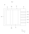
- FIG. 1 is a perspective view of the optical member 10.
- FIG. 2 is a top view of the optical member 10.
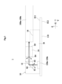
- FIG. 3 is a perspective view of the optical device 1.
- FIG. 4 is an exploded view of the optical device 1.
- FIG. 5 is a diagram of the lens portion 14 viewed in the negative direction of the X-axis.
- FIG. 6 is a perspective view of the optical device 1001.
- FIG. 7 is a perspective view of the optical device 1a.
- FIG. 8 is a perspective view of the optical device 1b.
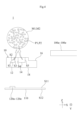
- FIG. 9 is a perspective view of the gradient index lens 140.
- FIG. 10 is a perspective view of the gradient index lens 142.
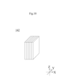
- FIG. 11 is a perspective view of the gradient index lenses 14a to 14e of the optical member 10c.
- FIG. 1 is a perspective view of the optical member 10.
- FIG. 2 is a top view of the optical member 10.
- FIG. 3 is a perspective view of the optical device 1.
- FIG. 4 is an exploded view of the optical device 1.
- FIG. 5 is a diagram of the lens portion 14 viewed in the negative direction of the X-axis.
- direction is defined as follows. As shown in FIG. 3, the direction in which the light emitting elements 120a to 120e emit light is defined as the positive direction of the Z axis. The direction in which the light reflected by the prism 12 travels is defined as the positive direction of the X-axis. The direction in which the optical fibers 100a to 100e are lined up is defined as the positive direction of the Y axis. The X-axis, Y-axis, and Z-axis are orthogonal to each other. Moreover, the X-axis, Y-axis, and Z-axis in this embodiment do not need to correspond with the X-axis, Y-axis, and Z-axis when the optical device 1 is used.
- the optical device 1 is a transmitting device of an optical communication system. As shown in FIGS. 3 and 4, the optical device 1 includes an optical member 10, optical fibers 100a to 100e, a circuit board 110, and light emitting elements 120a to 120e.
- the optical member 10 has a function of forming an optical path, a function of condensing light, and a function of changing the traveling direction of light. More specifically, the optical member 10 includes a prism 12, a lens section 14, a holding section 16, and a frame 18, as shown in FIGS. 1 and 2.
- the prism 12 is a second optical element that includes a medium M2 and a plurality of fillers P2 provided in the medium M2 and having an aspherical shape.
- the prism 12 changes the traveling direction of light passing through the medium M2.
- the prism 12 has a right isosceles triangular shape when viewed in the Y-axis direction.
- the prism 12 has an entrance surface S1 through which light enters, a reflection surface S2 through which light is reflected, and an exit surface S3 through which light exits.
- the entrance surface S1 has a normal line extending toward the negative direction of the Z axis.
- the reflective surface S2 has a normal line extending in the positive direction of the Z-axis and in the negative direction of the X-axis.
- the exit surface S3 has a normal extending in the positive direction of the X-axis.
- the medium M2 of the prism 12 is glass.
- Glass is a material that is amorphous and exhibits a glass transition phenomenon.
- the glass include simple oxide glasses such as SiO 2 , B 2 O 3 , P 2 O 5 , GeO 2 , As 2 O 3 , Li 2 O--SiO 2 , Na 2 O--SiO 2 , K 2 silicate glasses such as O-SiO 2 , aluminosilicate glasses such as Na 2 O-Al 2 O 3 -SiO 2 , CaO-Al 2 O 3 -SiO 2 , LiO 2 -Ba 2 -O 3 , Borate glasses such as Na2O - B2O3 , aluminoborate glasses such as CaO- Al2O3 - B2O3 , Na2O - Al2O3 -B2O3 - SiO It is a second class borosilicate glass.
- the plurality of fillers P2 are metal oxide particles such as crystalline silica, amorphous silica, alumina, magnesium oxide, and titanium oxide.
- the refractive index of the plurality of fillers is a value between the upper limit value n1 and the lower limit value n2 of the refractive index of the medium M2 of the prism 12 (second optical element).
- the refractive index of the plurality of fillers P2 and the refractive index of the medium M2 be close to each other.
- the higher the amorphousness of the plurality of fillers P2 the higher the transparency of the plurality of fillers P2.
- the plurality of fillers P2 have a non-spherical shape.
- a non-spherical shape is a shape that is not a sphere.
- a non-spherical shape is a shape in which the distance from the center to the outer edge is not constant, such as a rectangular parallelepiped shape or an ellipsoidal shape.
- the non-spherical shape may be a shape in which a large number of irregularities are provided on the surface of a sphere.
- the plurality of fillers P2 have an ellipsoidal shape.
- the plurality of fillers P2 have a longitudinal direction and a lateral direction. The longitudinal direction is the length direction of the longest portion of the plurality of fillers P2.
- the lateral direction is the length direction of the shortest portion of the plurality of fillers P2 among the directions orthogonal to the longitudinal direction.
- L1 be the length of the plurality of fillers P2 in the longitudinal direction.
- L2 be the length of the plurality of fillers P2 in the lateral direction.
- the wavelength of light be ⁇ .
- L2/L1>L1/ ⁇ holds true. Note that L1 and L2 are average values of 20 of the plurality of fillers P2 included in the prism 12.
- the plurality of fillers P2 are uniformly dispersed throughout the prism 12. Thereby, the plurality of fillers P2 are provided on the optical path. In particular, the plurality of fillers P2 are provided on the entrance surface S1.
- the lens section 14 includes gradient index lenses 14a to 14e and a support section 14f.
- the gradient index lenses 14a to 14e are arranged in this order toward the positive direction of the Y-axis. Since the gradient index lenses 14a to 14e have the same structure, the gradient index lens 14a will be described as an example.
- the gradient index lens 14a has a cylindrical shape with a central axis extending in the front-rear direction.
- the gradient index lens 14a has an entrance surface S4 and an exit surface S5, as shown in FIG.
- the entrance surface S4 and the exit surface S5 are arranged in this order in the positive direction of the X-axis.
- the entrance surface S4 has a normal line extending toward the negative direction of the X-axis.
- the exit surface S5 has a normal extending in the positive direction of the X-axis.
- the gradient index lens 14a is a first optical element that includes a medium M1 and a plurality of fillers P1 provided in the medium M1 and having an aspherical shape.
- the gradient index lens 14a changes the traveling direction of light passing through the medium M1. Specifically, as shown in FIG. 5, the refractive index of the gradient index lens 14a decreases as it moves away from the central axis of the gradient index lens 14a when viewed in the X-axis direction. Thereby, as shown in FIG. 3, the gradient index lens 14a condenses the light traveling in the positive direction of the X-axis within the medium M1 to a focal point located on the central axis of the gradient index lens 14a. . The focal point is located on the positive side of the X-axis from the exit surface S5. As a result, the gradient index lens 14a can change the diameter of light.
- the medium M1 of the gradient index lens 14a is glass.
- Glass is a material that is amorphous and exhibits a glass transition phenomenon.
- the glass include simple oxide glasses such as SiO 2 , B 2 O 3 , P 2 O 5 , GeO 2 , As 2 O 3 , Li 2 O-SiO 2 , Na 2 O-SiO 2 , K 2 silicate glasses such as O-SiO 2 , aluminosilicate glasses such as Na 2 O-Al 2 O 3 -SiO 2 , CaO-Al 2 O 3 -SiO 2 , LiO 2 -Ba 2 -O 3 , Borate glasses such as Na2O - B2O3 , aluminoborate glasses such as CaO- Al2O3 - B2O3 , Na2O - Al2O3 -B2O3 - SiO It is a second class borosilicate glass.
- Examples of methods for giving the gradient index lens 14a a refractive index distribution include the method described below. By impregnating cylindrical glass with molten salt, ions in the glass are replaced with ions in the molten salt, and metal ions permeate the cylindrical glass.
- the plurality of fillers P1 are metal oxide particles such as crystalline silica, amorphous silica, alumina, magnesium oxide, and titanium oxide.
- the refractive index of the plurality of fillers P1 is a value between the upper limit value n1 and the lower limit value n2 of the refractive index of the medium M1 of the gradient index lens 14a (first optical element).
- the refractive index of the plurality of fillers P1 and the refractive index of the medium M1 be close to each other.
- the plurality of fillers P1 have a non-spherical shape. Specifically, the plurality of fillers P1 have an ellipsoidal shape.
- the plurality of fillers P1 have a longitudinal direction and a lateral direction.
- the longitudinal direction is the length direction of the longest portion of the plurality of fillers P1.
- the lateral direction is the length direction of the shortest portion of the plurality of fillers P1 among the directions perpendicular to the longitudinal direction.
- L1 be the length of the plurality of fillers P1 in the longitudinal direction.
- L2 be the length of the plurality of fillers P1 in the lateral direction.
- the wavelength of light be ⁇ . At this time, L2/L1>L1/ ⁇ holds true. Note that L1 and L2 are average values of 20 fillers among the plurality of fillers P1 included in the gradient index lens 14a.
- the plurality of fillers P1 are uniformly dispersed throughout the gradient index lenses 14a to 14e. Thereby, the plurality of fillers P1 are provided on the optical path. In particular, the plurality of fillers P1 are provided on the entrance surface S4.
- the support portion 14f supports the gradient index lenses 14a to 14e. Specifically, the support portion 14f has an ellipsoidal shape.
- the gradient index lenses 14a to 14e are embedded in the support portion 14f. However, each of the entrance surfaces S4 of the gradient index lenses 14a to 14e is exposed from the negative side surface of the X-axis of the support portion 14f. Each of the exit surfaces S5 of the gradient index lenses 14a to 14e is exposed from the surface of the support portion 14f on the positive side of the X-axis.
- the material of the support portion 14f is the same glass as the medium M1 of the gradient index lens 14a.
- the gradient index lenses 14a to 14e as described above are located on the positive side of the X-axis of the prism 12. Thereby, the entrance surface S4 of the gradient index lenses 14a to 14e overlaps the exit surface S3 of the prism 12 when viewed in the X-axis direction.
- the holding part 16 holds the optical fiber 100a so that each of the lights emitted from the gradient index lenses 14a to 14e (first optical element) is incident on the end surface T of the optical fibers 100a to 100e. ⁇ Hold 100e. More specifically, the holding part 16 is located on the positive side of the X-axis of the lens part 14. As shown in FIG. 1, the holding portion 16 has a plate shape having a positive principal surface SP and a negative principal surface SM. The positive principal surface SP and the negative principal surface SM are arranged in this order in the negative direction of the Z-axis. Further, grooves 16a to 16e extending in the X-axis direction are provided on the front main surface SP of the holding portion 16.
- the grooves 16a to 16e are arranged in this order in the positive direction of the Y-axis.
- Each of the optical fibers 100a to 100e is fixed to the grooves 16a to 16e with an adhesive.
- the optical axes of the optical fibers 100a to 100e coincide with the central axes of the gradient index lenses 14a to 14e.
- the material of the holding part 16 is the same glass as the medium M2 of the prism 12 and the medium M1 of the gradient index lens 14a.
- the frame 18 supports the prism 12, the lens section 14, and the holding section 16. More specifically, the frame 18 includes support parts 18a, 18b and a connecting part 18c. Each of the support parts 18a and 18b is a plate having two main surfaces aligned in the Y-axis direction. The support portions 18a and 18b are arranged in this order in the negative direction of the Y-axis. The end of the holding portion 16 on the positive side of the Y-axis and the end of the lens portion 14 on the positive side of the Y-axis are in contact with the support portion 18a. The Y-axis negative end of the holding portion 16 and the Y-axis negative end of the lens portion 14 are in contact with the support portion 18b. The surface of the holding portion 16 located on the negative side of the X-axis is in contact with the positive end of the support portion 18a in the X-axis direction and the positive end of the support portion 18b in the X-axis direction.
- the connecting portion 18c is a plate having two main surfaces aligned in the X-axis direction.
- the end of the connecting portion 18c on the positive side of the Y axis is in contact with the supporting portion 18a.
- the Y-axis negative end of the connecting portion 18c is in contact with the supporting portion 18b.
- the material of the holding part 16 is the same glass as the medium M2 of the prism 12 and the medium M1 of the gradient index lens 14a.
- the lens portion 14 (first optical element), prism 12 (second optical element), holding portion 16, and frame 18 as described above are integrally molded. That is, the lens portion 14 (first optical element), prism 12 (second optical element), holding portion 16, and frame 18 cannot be separated without damaging them.
- the circuit board 110 has a plate shape, as shown in FIGS. 3 and 4. Therefore, the circuit board 110 has a positive principal surface S11 and a negative principal surface S12.
- the positive principal surface S11 is located on the positive side of the Z axis of the negative principal surface S12. Electric circuits such as wiring are provided on the surface and inside of the circuit board 110.
- the circuit board 110 is located on the negative side of the optical member 10 in the Z-axis direction.
- the light emitting elements 120a to 120e emit light in the positive direction of the Z axis.
- the light emitting elements 120a to 120e are, for example, vertical cavity surface emitting lasers (VCSEL).
- the wavelength of the light is, for example, 1310 nm.
- the light emitting elements 120a to 120e are mounted on the front main surface S11 of the circuit board 110.
- the light emitting elements 120a to 120e overlap the entrance surface S1 of the prism 12 when viewed in the Z-axis direction.
- the light emitting elements 120a to 120e emit light in the positive direction of the Z axis.
- the light travels in the positive direction of the Z-axis while the diameter expands in a direction perpendicular to the direction of travel, or while the diameter remains unchanged.
- the light emitted by the light emitting elements 120a to 120e enters the prism 12 (second optical element) via the entrance surface S1.
- the light travels in the positive direction of the X-axis by being reflected by the reflective surface S2.
- the light then exits from the prism 12 via the exit surface S3.
- the light emitted from the prism 12 enters the gradient index lenses 14a to 14e (first optical element) via the entrance surface S4.
- the light is focused when passing through the gradient index lenses 14a to 14e.
- the light then exits from the gradient index lenses 14a to 14e via the exit surface S5. After this, the light enters the optical fibers 100a-100e.
- FIG. 6 is a perspective view of the optical device 1001.
- the optical device 1001 differs from the optical device 1 in that the prism 1012 does not include a plurality of fillers P2, and the gradient index lenses 1014a to 1014e (not shown) do not include a plurality of fillers P1. .
- the semiconductor optical coupling device described in Patent Document 1 includes an optical isolator.
- the gradient index lenses 14a to 14e include a plurality of fillers P1.
- the prism 12 includes a plurality of fillers P2.
- part of the light is reflected by the plurality of fillers P1 while traveling in the medium M1.
- part of the light is reflected by the plurality of fillers P2 while traveling in the medium M2.
- the plurality of fillers P1 and P2 have a non-spherical shape. Therefore, the light reflected by the plurality of fillers P1 does not travel in the negative direction of the X-axis, as shown in FIG. 3.
- the light reflected by the plurality of fillers P2 does not travel in the negative direction of the Z-axis. Therefore, the light reflected by the plurality of fillers P1 and P2 becomes difficult to enter the light emitting elements 120a to 120e.
- the optical member 10 by providing the plurality of fillers P1 and P2 without adding a new element, reflected light is suppressed from entering the light emitting elements 120a to 120e. Therefore, the size of the optical member 10 and the cost of the optical member 10 can be reduced.
- the plurality of fillers P1 and P2 are provided on the optical path. Thereby, light becomes more likely to be reflected by the plurality of fillers P1 and P2.
- the plurality of fillers P1 and P2 are provided on the entrance surfaces S1 and S4.
- the light reflected by the incident surface S1 is reflected by the plurality of fillers P2 in a direction other than the negative direction of the Z axis.
- the light reflected by the entrance surface S4 is reflected by the plurality of fillers P1 in a direction other than the negative direction of the X-axis.
- the light reflected by the plurality of fillers P1 and P2 becomes difficult to enter the light emitting elements 120a to 120e.
- the refractive index of the plurality of fillers P1 is a value between the upper limit value n1 and the lower limit value n2 of the refractive index of the medium M1 of the gradient index lenses 14a to 14e. Therefore, the influence of the plurality of fillers P1 on the optical characteristics of the gradient index lenses 14a to 14e can be reduced.
- the length of the plurality of fillers P1 and P2 in the longitudinal direction is L1
- the length of the plurality of fillers P1 and P2 in the transverse direction is L2
- the wavelength of light is ⁇
- L2/L1>L1/ ⁇ holds true.
- Rayleigh scattering occurs.
- Spherical fillers increase backscattered components due to Rayleigh scattering, but non-spherical fillers can suppress this.
- the prism 12 and the gradient index lenses 14a to 14e are integrally molded. This suppresses variations in the positional relationship between the prism 12 and the gradient index lenses 14a to 14e.
- FIG. 7 is a perspective view of the optical device 1a.
- the optical member 10a differs from the optical member 10 in that it does not include a prism 12.
- each of the light emitting elements 120a to 120e is located on the negative side of the X axis of the gradient index lenses 14a to 14e. Then, the light emitted from each of the light emitting elements 120a to 120e enters the gradient index lenses 14a to 14e (first optical elements).
- the other structure of the optical member 10a is the same as that of the optical member 10, so a description thereof will be omitted.
- the optical member 10a can have the same effects as the optical member 10.
- FIG. 8 is a perspective view of the optical device 1b.
- FIG. 9 is a perspective view of the gradient index lens 140.
- FIG. 10 is a perspective view of the gradient index lens 142.
- the optical member 10b differs from the optical member 10a in that it includes a gradient index lens 140 (first optical element) and a gradient index lens 142 instead of gradient index lenses 14a to 14e (first optical elements). It differs from The refractive index of the gradient index lens 140 decreases as it moves away from the center in the Z-axis direction in the positive and negative directions of the Z-axis direction. Thereby, the gradient index lens 140 condenses light traveling in the positive direction of the X-axis so that the diameter thereof becomes smaller in the Z-axis direction. Further, the gradient index lens 140 includes a medium and a plurality of fillers.
- the refractive index of the gradient index lens 142 decreases as it moves away from the center in the Y-axis direction in the positive and negative directions of the Y-axis direction.
- the gradient index lens 142 condenses light traveling in the positive direction of the X-axis so that the diameter thereof becomes smaller in the Y-axis direction.
- the gradient index lens 142 includes a medium and a plurality of fillers.
- optical member 10b The other structure of the optical member 10b is the same as that of the optical member 10a, so a description thereof will be omitted.
- the optical member 10b can have the same effects as the optical member 10a.
- FIG. 11 is a perspective view of the gradient index lenses 14a to 14e of the optical member 10c.
- the optical member 10c differs from the optical member 10 in the positions where the plurality of fillers P1 are provided. More specifically, the gradient index lenses 14a to 14e have a focal point. The condensing point is a position where the diameter of light is the smallest in the gradient index lenses 14a to 14e (first optical element). The plurality of fillers P1 are located at the focal point. Thereby, the light is effectively scattered by the plurality of fillers P1.
- the rest of the structure of the optical member 10c is the same as that of the optical member 10, so a description thereof will be omitted.
- the optical member 10c can have the same effects as the optical member 10.
- optical member according to the present invention is not limited to the optical members 10, 10a to 10c, and can be modified within the scope of the gist thereof. Furthermore, the structures of the optical members 10, 10a to 10c may be combined arbitrarily.
- first optical element and the second optical element may be optical elements other than the prism and the gradient index lens.
- the plurality of fillers may be provided at positions other than the light condensing point. Further, the plurality of fillers may not be provided at the light condensing point.
- the plurality of fillers do not need to be provided on the incident surface.
- the optical device may include a receiving device in addition to the transmitting device. That is, the optical device may include a light receiving element in addition to the light emitting element.
- the first optical element and the second optical element corresponding to the light emitting element may include a medium and a plurality of fillers.
- the positions of the gradient index lens 140 and the gradient index lens 142 may be switched.
- the optical member may not include a gradient index lens but may include a prism.
- the prism is the first optical element.
- the refractive index of the gradient index lens may change stepwise.
- Optical device 10 10a to 10c: Optical member 12: Prism 14: Lens parts 14a to 14e, 140, 142: Gradient index lens 14f: Supporting part 16: Holding parts 16a to 16e: Groove 18 : Frame bodies 18a, 18b: Support part 18c: Connecting parts 100a to 100e: Optical fiber 110: Circuit board 120a to 120e: Light emitting elements M1, M2: Medium P1, P2: Filler S1, S4: Incident surface S11, SP: Positive Principal surface S12, SM: Negative principal surface S2: Reflective surface S3, S5: Output surface T: End surface
Abstract
The optical member according to the present invention comprises: first optical elements (12, 14) that include media (M1, M2) and a plurality of aspherical fillers (P1, P2) provided in the media, and that change the traveling direction of light passing in the media; and a holding part (16) that holds optical fibers (100) such that light emitted from the first optical elements enters end surfaces of the optical fibers.
Description
本発明は、光学部材及び光学装置に関する。
The present invention relates to an optical member and an optical device.
従来の光学部材に関する発明としては、例えば、特許文献1に記載の半導体光結合装置が知られている。この半導体光結合装置は、レーザダイオード、光アイソレータ及び光ファイバを備えている。レーザダイオードは、光を出射する。レーザダイオードが出射した光は、光アイソレータを通過して、光ファイバの端面に入射する。光アイソレータは、光ファイバの端面等により反射された光が、レーザダイオードに入射することを抑制する。
As an invention related to a conventional optical member, for example, a semiconductor optical coupling device described in Patent Document 1 is known. This semiconductor optical coupling device includes a laser diode, an optical isolator, and an optical fiber. A laser diode emits light. The light emitted by the laser diode passes through the optical isolator and enters the end face of the optical fiber. The optical isolator prevents light reflected by the end face of the optical fiber from entering the laser diode.
ところで、特許文献1に記載の半導体光結合装置において、半導体光結合装置の小型化及び半導体光結合装置の低コスト化を図ることが望まれている。
By the way, in the semiconductor optical coupling device described in Patent Document 1, it is desired to reduce the size of the semiconductor optical coupling device and the cost reduction of the semiconductor optical coupling device.
そこで、本発明の目的は、光学部材の小型化及び光学部材の低コスト化を図ることができる光学部材及び光学装置を提供することである。
Therefore, an object of the present invention is to provide an optical member and an optical device that can reduce the size of the optical member and the cost of the optical member.
本発明の一形態に係る光学部材は、
媒質と、前記媒質内に設けられ、かつ、非球形状を有する複数のフィラーと、を含んでいる第1光学素子であって、前記媒質内を通過する光の進行方向を変化させる第1光学素子と、
前記第1光学素子から出射した光が光ファイバの端面に入射するように、前記光ファイバを保持する保持部と、
を備えている。 An optical member according to one embodiment of the present invention includes:
A first optical element including a medium and a plurality of fillers provided in the medium and having an aspherical shape, the first optical element changing the traveling direction of light passing through the medium. Motoko and
a holding part that holds the optical fiber so that the light emitted from the first optical element is incident on the end face of the optical fiber;
It is equipped with
本発明に光学部材の小型化及び光学部材の低コスト化を図ることができる。
According to the present invention, the size of the optical member and the cost of the optical member can be reduced.
(実施形態)
以下に、本発明の一実施形態に係る光学部材10を備える光学装置1について図面を参照しながら説明する。図1は、光学部材10の斜視図である。図2は、光学部材10の上面図である。図3は、光学装置1の透視図である。図4は、光学装置1の分解図である。図5は、レンズ部14をX軸の負方向に見た図である。 (Embodiment)
Anoptical device 1 including an optical member 10 according to an embodiment of the present invention will be described below with reference to the drawings. FIG. 1 is a perspective view of the optical member 10. FIG. 2 is a top view of the optical member 10. FIG. 3 is a perspective view of the optical device 1. FIG. 4 is an exploded view of the optical device 1. FIG. 5 is a diagram of the lens portion 14 viewed in the negative direction of the X-axis.
以下に、本発明の一実施形態に係る光学部材10を備える光学装置1について図面を参照しながら説明する。図1は、光学部材10の斜視図である。図2は、光学部材10の上面図である。図3は、光学装置1の透視図である。図4は、光学装置1の分解図である。図5は、レンズ部14をX軸の負方向に見た図である。 (Embodiment)
An
本明細書において、方向を以下のように定義する。図3に示すように、発光素子120a~120eが光を放射する方向をZ軸の正方向と定義する。プリズム12により反射された光が進行する方向をX軸の正方向と定義する。光ファイバ100a~100eが並ぶ方向をY軸の正方向と定義する。X軸、Y軸及びZ軸は、互いに直交している。また、本実施形態におけるX軸、Y軸及びZ軸は、光学装置1の使用時におけるX軸、Y軸及びZ軸と一致していなくてもよい。
In this specification, direction is defined as follows. As shown in FIG. 3, the direction in which the light emitting elements 120a to 120e emit light is defined as the positive direction of the Z axis. The direction in which the light reflected by the prism 12 travels is defined as the positive direction of the X-axis. The direction in which the optical fibers 100a to 100e are lined up is defined as the positive direction of the Y axis. The X-axis, Y-axis, and Z-axis are orthogonal to each other. Moreover, the X-axis, Y-axis, and Z-axis in this embodiment do not need to correspond with the X-axis, Y-axis, and Z-axis when the optical device 1 is used.
光学装置1は、光通信システムの送信装置である。光学装置1は、図3及び図4に示すように、光学部材10、光ファイバ100a~100e、回路基板110及び発光素子120a~120eを備えている。
The optical device 1 is a transmitting device of an optical communication system. As shown in FIGS. 3 and 4, the optical device 1 includes an optical member 10, optical fibers 100a to 100e, a circuit board 110, and light emitting elements 120a to 120e.
光学部材10は、光路を形成する機能、集光する機能、及び、光の進行方向を変化させる機能を有している。より詳細には、光学部材10は、図1及び図2に示すように、プリズム12、レンズ部14、保持部16及び枠体18を備えている。
The optical member 10 has a function of forming an optical path, a function of condensing light, and a function of changing the traveling direction of light. More specifically, the optical member 10 includes a prism 12, a lens section 14, a holding section 16, and a frame 18, as shown in FIGS. 1 and 2.
プリズム12は、図3及び図4に示すように、媒質M2と、媒質M2内に設けられ、かつ、非球形状を有する複数のフィラーP2と、を含んでいる第2光学素子である。プリズム12は、媒質M2内を通過する光の進行方向を変化させる。具体的には、プリズム12は、Y軸方向に見て、直角二等辺三角形状を有している。プリズム12は、光が入射する入射面S1、光が反射する反射面S2及び光が出射する出射面S3を有している。入射面S1は、Z軸の負方向に向かって延びる法線を有している。反射面S2は、Z軸の正方向かつX軸の負方向に向かって延びる法線を有している。出射面S3は、X軸の正方向に向かって延びる法線を有している。
As shown in FIGS. 3 and 4, the prism 12 is a second optical element that includes a medium M2 and a plurality of fillers P2 provided in the medium M2 and having an aspherical shape. The prism 12 changes the traveling direction of light passing through the medium M2. Specifically, the prism 12 has a right isosceles triangular shape when viewed in the Y-axis direction. The prism 12 has an entrance surface S1 through which light enters, a reflection surface S2 through which light is reflected, and an exit surface S3 through which light exits. The entrance surface S1 has a normal line extending toward the negative direction of the Z axis. The reflective surface S2 has a normal line extending in the positive direction of the Z-axis and in the negative direction of the X-axis. The exit surface S3 has a normal extending in the positive direction of the X-axis.
プリズム12の媒質M2は、ガラスである。ガラスは、非晶質であり、かつ、ガラス転移現象を示す材料である。ガラスは、例えば、SiO2,B2O3,P2O5,GeO2,As2O3等の単純酸化物のガラスや、Li2O-SiO2,Na2O-SiO2,K2O-SiO2等のケイ酸塩のガラス、Na2O-Al2O3-SiO2,CaO-Al2O3-SiO2等のアルミノケイ酸塩のガラス、LiO2-Ba2-O3,Na2O-B2O3等のホウ酸塩のガラス、CaO-Al2O3-B2O3等のアルミノホウ酸塩のガラス、Na2O-Al2O3-B2O3-SiO2等のホウケイ酸塩のガラスである。
The medium M2 of the prism 12 is glass. Glass is a material that is amorphous and exhibits a glass transition phenomenon. Examples of the glass include simple oxide glasses such as SiO 2 , B 2 O 3 , P 2 O 5 , GeO 2 , As 2 O 3 , Li 2 O--SiO 2 , Na 2 O--SiO 2 , K 2 silicate glasses such as O-SiO 2 , aluminosilicate glasses such as Na 2 O-Al 2 O 3 -SiO 2 , CaO-Al 2 O 3 -SiO 2 , LiO 2 -Ba 2 -O 3 , Borate glasses such as Na2O - B2O3 , aluminoborate glasses such as CaO- Al2O3 - B2O3 , Na2O - Al2O3 -B2O3 - SiO It is a second class borosilicate glass.
複数のフィラーP2は、結晶性シリカ、非晶質シリカ、アルミナ、酸化マグネシウム、酸化チタン等の金属酸化物粒子である。複数のフィラーの屈折率は、プリズム12(第2光学素子)の媒質M2の屈折率の上限値n1と下限値n2との間の値である。ただし、界面での屈折率差による反射を抑制するため、複数のフィラーP2の屈折率と媒質M2の屈折率が近い方が好ましい。また、複数のフィラーP2の非晶質性が高くなる程に、複数のフィラーP2の透過性が高いことが好ましい。
The plurality of fillers P2 are metal oxide particles such as crystalline silica, amorphous silica, alumina, magnesium oxide, and titanium oxide. The refractive index of the plurality of fillers is a value between the upper limit value n1 and the lower limit value n2 of the refractive index of the medium M2 of the prism 12 (second optical element). However, in order to suppress reflection due to a difference in refractive index at the interface, it is preferable that the refractive index of the plurality of fillers P2 and the refractive index of the medium M2 be close to each other. Moreover, it is preferable that the higher the amorphousness of the plurality of fillers P2, the higher the transparency of the plurality of fillers P2.
複数のフィラーP2は、非球形状を有している。非球形状とは、球ではない形状である。球ではない形状は、中心から外縁までの距離が一定ではない形状であり、例えば、直方体状や楕円球形状である。また、非球形状とは、球の表面に多数の凹凸が設けられた形状であってもよい。本実施形態では、複数のフィラーP2は、楕円球形状を有している。そして、複数のフィラーP2は、長手方向及び短手方向を有している。長手方向は、複数のフィラーP2における最長部分の長さ方向である。短手方向は、長手方向に直交する方向の内で、複数のフィラーP2における最短部分の長さ方向である。複数のフィラーP2の長手方向の長さをL1とする。複数のフィラーP2の短手方向の長さをL2とする。光の波長をλとする。このとき、L2/L1>L1/λが成立している。なお、L1,L2は、プリズム12に含まれる複数のフィラーP2の内の20個の平均値である。
The plurality of fillers P2 have a non-spherical shape. A non-spherical shape is a shape that is not a sphere. A non-spherical shape is a shape in which the distance from the center to the outer edge is not constant, such as a rectangular parallelepiped shape or an ellipsoidal shape. Moreover, the non-spherical shape may be a shape in which a large number of irregularities are provided on the surface of a sphere. In this embodiment, the plurality of fillers P2 have an ellipsoidal shape. The plurality of fillers P2 have a longitudinal direction and a lateral direction. The longitudinal direction is the length direction of the longest portion of the plurality of fillers P2. The lateral direction is the length direction of the shortest portion of the plurality of fillers P2 among the directions orthogonal to the longitudinal direction. Let L1 be the length of the plurality of fillers P2 in the longitudinal direction. Let L2 be the length of the plurality of fillers P2 in the lateral direction. Let the wavelength of light be λ. At this time, L2/L1>L1/λ holds true. Note that L1 and L2 are average values of 20 of the plurality of fillers P2 included in the prism 12.
また、複数のフィラーP2は、プリズム12の全体に均一に分散している。これにより、複数のフィラーP2は、光の経路上に設けられている。特に、複数のフィラーP2は、入射面S1に設けられている。
Furthermore, the plurality of fillers P2 are uniformly dispersed throughout the prism 12. Thereby, the plurality of fillers P2 are provided on the optical path. In particular, the plurality of fillers P2 are provided on the entrance surface S1.
レンズ部14は、図1に示すように、屈折率分布型レンズ14a~14e及び支持部14fを含んでいる。屈折率分布型レンズ14a~14eは、Y軸の正方向に向かってこの順に並んでいる。屈折率分布型レンズ14a~14eの構造は同じであるので、屈折率分布型レンズ14aを例に挙げて説明する。
As shown in FIG. 1, the lens section 14 includes gradient index lenses 14a to 14e and a support section 14f. The gradient index lenses 14a to 14e are arranged in this order toward the positive direction of the Y-axis. Since the gradient index lenses 14a to 14e have the same structure, the gradient index lens 14a will be described as an example.
屈折率分布型レンズ14aは、前後方向に延びる中心軸線を有する円柱形状を有している。屈折率分布型レンズ14aは、図3に示すように、入射面S4及び出射面S5を有している。入射面S4及び出射面S5は、X軸の正方向にこの順に並んでいる。入射面S4は、X軸の負方向に向かって延びる法線を有している。出射面S5は、X軸の正方向に向かって延びる法線を有している。
The gradient index lens 14a has a cylindrical shape with a central axis extending in the front-rear direction. The gradient index lens 14a has an entrance surface S4 and an exit surface S5, as shown in FIG. The entrance surface S4 and the exit surface S5 are arranged in this order in the positive direction of the X-axis. The entrance surface S4 has a normal line extending toward the negative direction of the X-axis. The exit surface S5 has a normal extending in the positive direction of the X-axis.
屈折率分布型レンズ14aは、図4に示すように、媒質M1と、媒質M1内に設けられ、かつ、非球形状を有する複数のフィラーP1と、を含んでいる第1光学素子である。屈折率分布型レンズ14aは、媒質M1内を通過する光の進行方向を変化させる。具体的には、屈折率分布型レンズ14aの屈折率は、図5に示すように、X軸方向に見て、屈折率分布型レンズ14aの中心軸線から離れるにしたがって小さくなっている。これにより、屈折率分布型レンズ14aは、図3に示すように、媒質M1内をX軸の正方向に進行する光を屈折率分布型レンズ14aの中心軸線上に位置する焦点に集光する。焦点は、出射面S5よりX軸の正側に位置している。その結果、屈折率分布型レンズ14aは、光の径を変化させることができる。
As shown in FIG. 4, the gradient index lens 14a is a first optical element that includes a medium M1 and a plurality of fillers P1 provided in the medium M1 and having an aspherical shape. The gradient index lens 14a changes the traveling direction of light passing through the medium M1. Specifically, as shown in FIG. 5, the refractive index of the gradient index lens 14a decreases as it moves away from the central axis of the gradient index lens 14a when viewed in the X-axis direction. Thereby, as shown in FIG. 3, the gradient index lens 14a condenses the light traveling in the positive direction of the X-axis within the medium M1 to a focal point located on the central axis of the gradient index lens 14a. . The focal point is located on the positive side of the X-axis from the exit surface S5. As a result, the gradient index lens 14a can change the diameter of light.
屈折率分布型レンズ14aの媒質M1は、ガラスである。ガラスは、非晶質であり、かつ、ガラス転移現象を示す材料である。ガラスは、例えば、SiO2,B2O3,P2O5,GeO2,As2O3等の単純酸化物のガラスや、Li2O-SiO2,Na2O-SiO2,K2O-SiO2等のケイ酸塩のガラス、Na2O-Al2O3-SiO2,CaO-Al2O3-SiO2等のアルミノケイ酸塩のガラス、LiO2-Ba2-O3,Na2O-B2O3等のホウ酸塩のガラス、CaO-Al2O3-B2O3等のアルミノホウ酸塩のガラス、Na2O-Al2O3-B2O3-SiO2等のホウケイ酸塩のガラスである。
The medium M1 of the gradient index lens 14a is glass. Glass is a material that is amorphous and exhibits a glass transition phenomenon. Examples of the glass include simple oxide glasses such as SiO 2 , B 2 O 3 , P 2 O 5 , GeO 2 , As 2 O 3 , Li 2 O-SiO 2 , Na 2 O-SiO 2 , K 2 silicate glasses such as O-SiO 2 , aluminosilicate glasses such as Na 2 O-Al 2 O 3 -SiO 2 , CaO-Al 2 O 3 -SiO 2 , LiO 2 -Ba 2 -O 3 , Borate glasses such as Na2O - B2O3 , aluminoborate glasses such as CaO- Al2O3 - B2O3 , Na2O - Al2O3 -B2O3 - SiO It is a second class borosilicate glass.
屈折率分布型レンズ14aに屈折率分布を持たせる方法としては、以下に説明する方法が挙げられる。円柱形状のガラスを溶融塩に含浸させることにより、ガラス中のイオンを溶融塩中のイオンに置換して、円柱形状のガラスに金属イオンを浸透させる。
Examples of methods for giving the gradient index lens 14a a refractive index distribution include the method described below. By impregnating cylindrical glass with molten salt, ions in the glass are replaced with ions in the molten salt, and metal ions permeate the cylindrical glass.
複数のフィラーP1は、結晶性シリカ、非晶質シリカ、アルミナ、酸化マグネシウム、酸化チタン等の金属酸化物粒子である。複数のフィラーP1の屈折率は、屈折率分布型レンズ14a(第1光学素子)の媒質M1の屈折率の上限値n1と下限値n2との間の値である。ただし、界面での屈折率差による反射を抑制するため、複数のフィラーP1の屈折率と媒質M1の屈折率が近い方が好ましい。また、複数のフィラーP1の非晶質性が高くなる程に、複数のフィラーP1の透過性が高いことが好ましい。
The plurality of fillers P1 are metal oxide particles such as crystalline silica, amorphous silica, alumina, magnesium oxide, and titanium oxide. The refractive index of the plurality of fillers P1 is a value between the upper limit value n1 and the lower limit value n2 of the refractive index of the medium M1 of the gradient index lens 14a (first optical element). However, in order to suppress reflection due to a difference in refractive index at the interface, it is preferable that the refractive index of the plurality of fillers P1 and the refractive index of the medium M1 be close to each other. Moreover, it is preferable that the higher the amorphousness of the plurality of fillers P1, the higher the transmittance of the plurality of fillers P1.
複数のフィラーP1は、非球形状を有している。具体的には、複数のフィラーP1は、楕円球形状を有している。そして、複数のフィラーP1は、長手方向及び短手方向を有している。長手方向は、複数のフィラーP1における最長部分の長さ方向である。短手方向は、長手方向に直交する方向の内で、複数のフィラーP1における最短部分の長さ方向である。複数のフィラーP1の長手方向の長さをL1とする。複数のフィラーP1の短手方向の長さをL2とする。光の波長をλとする。このとき、L2/L1>L1/λが成立している。なお、L1,L2は、屈折率分布型レンズ14aに含まれる複数のフィラーP1の内の20個の平均値である。
The plurality of fillers P1 have a non-spherical shape. Specifically, the plurality of fillers P1 have an ellipsoidal shape. The plurality of fillers P1 have a longitudinal direction and a lateral direction. The longitudinal direction is the length direction of the longest portion of the plurality of fillers P1. The lateral direction is the length direction of the shortest portion of the plurality of fillers P1 among the directions perpendicular to the longitudinal direction. Let L1 be the length of the plurality of fillers P1 in the longitudinal direction. Let L2 be the length of the plurality of fillers P1 in the lateral direction. Let the wavelength of light be λ. At this time, L2/L1>L1/λ holds true. Note that L1 and L2 are average values of 20 fillers among the plurality of fillers P1 included in the gradient index lens 14a.
また、複数のフィラーP1は、屈折率分布型レンズ14a~14eの全体に均一に分散している。これにより、複数のフィラーP1は、光の経路上に設けられている。特に、複数のフィラーP1は、入射面S4に設けられている。
Further, the plurality of fillers P1 are uniformly dispersed throughout the gradient index lenses 14a to 14e. Thereby, the plurality of fillers P1 are provided on the optical path. In particular, the plurality of fillers P1 are provided on the entrance surface S4.
支持部14fは、屈折率分布型レンズ14a~14eを支持している。具体的には、支持部14fは、楕円球形状を有している。屈折率分布型レンズ14a~14eは、支持部14fに埋め込まれている。ただし、屈折率分布型レンズ14a~14eの入射面S4のそれぞれは、支持部14fのX軸の負側の面から露出している。屈折率分布型レンズ14a~14eの出射面S5のそれぞれは、支持部14fのX軸の正側の面から露出している。支持部14fの材料は、屈折率分布型レンズ14aの媒質M1と同じガラスである。
The support portion 14f supports the gradient index lenses 14a to 14e. Specifically, the support portion 14f has an ellipsoidal shape. The gradient index lenses 14a to 14e are embedded in the support portion 14f. However, each of the entrance surfaces S4 of the gradient index lenses 14a to 14e is exposed from the negative side surface of the X-axis of the support portion 14f. Each of the exit surfaces S5 of the gradient index lenses 14a to 14e is exposed from the surface of the support portion 14f on the positive side of the X-axis. The material of the support portion 14f is the same glass as the medium M1 of the gradient index lens 14a.
以上のような屈折率分布型レンズ14a~14eは、プリズム12のX軸の正側に位置している。これにより、屈折率分布型レンズ14a~14eの入射面S4は、X軸方向に見て、プリズム12の出射面S3と重なっている。
The gradient index lenses 14a to 14e as described above are located on the positive side of the X-axis of the prism 12. Thereby, the entrance surface S4 of the gradient index lenses 14a to 14e overlaps the exit surface S3 of the prism 12 when viewed in the X-axis direction.
保持部16は、図3に示すように、屈折率分布型レンズ14a~14e(第1光学素子)から出射した光のそれぞれが光ファイバ100a~100eの端面Tに入射するように、光ファイバ100a~100eを保持する。より詳細には、保持部16は、レンズ部14のX軸の正側に位置している。保持部16は、図1に示すように、正主面SP及び負主面SMを有する板形状を有している。正主面SP及び負主面SMは、Z軸の負方向にこの順に並んでいる。また、保持部16の正主面SPには、X軸方向に延びる溝16a~16eが設けられている。溝16a~16eは、Y軸の正方向にこの順に並んでいる。光ファイバ100a~100eのそれぞれは、接着剤により溝16a~16eに固定されている。このとき、光ファイバ100a~100eのそれぞれの光軸は、屈折率分布型レンズ14a~14eの中心軸線と一致している。保持部16の材料は、プリズム12の媒質M2及び屈折率分布型レンズ14aの媒質M1と同じガラスである。
As shown in FIG. 3, the holding part 16 holds the optical fiber 100a so that each of the lights emitted from the gradient index lenses 14a to 14e (first optical element) is incident on the end surface T of the optical fibers 100a to 100e. ~Hold 100e. More specifically, the holding part 16 is located on the positive side of the X-axis of the lens part 14. As shown in FIG. 1, the holding portion 16 has a plate shape having a positive principal surface SP and a negative principal surface SM. The positive principal surface SP and the negative principal surface SM are arranged in this order in the negative direction of the Z-axis. Further, grooves 16a to 16e extending in the X-axis direction are provided on the front main surface SP of the holding portion 16. The grooves 16a to 16e are arranged in this order in the positive direction of the Y-axis. Each of the optical fibers 100a to 100e is fixed to the grooves 16a to 16e with an adhesive. At this time, the optical axes of the optical fibers 100a to 100e coincide with the central axes of the gradient index lenses 14a to 14e. The material of the holding part 16 is the same glass as the medium M2 of the prism 12 and the medium M1 of the gradient index lens 14a.
枠体18は、プリズム12、レンズ部14及び保持部16を支持している。より詳細には、枠体18は、支持部18a,18b及び連結部18cを含んでいる。支持部18a,18bのそれぞれは、Y軸方向に並ぶ2つの主面を有する板である。支持部18a,18bは、Y軸の負方向にこの順に並んでいる。保持部16のY軸の正側の端、及び、レンズ部14のY軸の正側の端は、支持部18aに接している。保持部16のY軸の負側の端、及び、レンズ部14のY軸の負側の端は、支持部18bに接している。保持部16のX軸の負側に位置する面は、支持部18aのX軸方向の正側の端、及び、支持部18bのX軸方向の正側の端に接している。
The frame 18 supports the prism 12, the lens section 14, and the holding section 16. More specifically, the frame 18 includes support parts 18a, 18b and a connecting part 18c. Each of the support parts 18a and 18b is a plate having two main surfaces aligned in the Y-axis direction. The support portions 18a and 18b are arranged in this order in the negative direction of the Y-axis. The end of the holding portion 16 on the positive side of the Y-axis and the end of the lens portion 14 on the positive side of the Y-axis are in contact with the support portion 18a. The Y-axis negative end of the holding portion 16 and the Y-axis negative end of the lens portion 14 are in contact with the support portion 18b. The surface of the holding portion 16 located on the negative side of the X-axis is in contact with the positive end of the support portion 18a in the X-axis direction and the positive end of the support portion 18b in the X-axis direction.
連結部18cは、X軸方向に並ぶ2つの主面を有する板である。連結部18cのY軸の正側の端は、支持部18aに接している。連結部18cのY軸の負側の端は、支持部18bに接している。保持部16の材料は、プリズム12の媒質M2及び屈折率分布型レンズ14aの媒質M1と同じガラスである。
The connecting portion 18c is a plate having two main surfaces aligned in the X-axis direction. The end of the connecting portion 18c on the positive side of the Y axis is in contact with the supporting portion 18a. The Y-axis negative end of the connecting portion 18c is in contact with the supporting portion 18b. The material of the holding part 16 is the same glass as the medium M2 of the prism 12 and the medium M1 of the gradient index lens 14a.
以上のようなレンズ部14(第1光学素子)とプリズム12(第2光学素子)と保持部16と枠体18とは、一体成型されている。すなわち、レンズ部14(第1光学素子)とプリズム12(第2光学素子)と保持部16と枠体18とは、破損させることなく分離することができない。
The lens portion 14 (first optical element), prism 12 (second optical element), holding portion 16, and frame 18 as described above are integrally molded. That is, the lens portion 14 (first optical element), prism 12 (second optical element), holding portion 16, and frame 18 cannot be separated without damaging them.
回路基板110は、図3及び図4に示すように、板形状を有している。従って、回路基板110は、正主面S11及び負主面S12を有している。正主面S11は、負主面S12のZ軸の正側に位置している。回路基板110の表面及び内部には、配線等の電気回路が設けられている。回路基板110は、光学部材10のZ軸方向の負側に位置している。
The circuit board 110 has a plate shape, as shown in FIGS. 3 and 4. Therefore, the circuit board 110 has a positive principal surface S11 and a negative principal surface S12. The positive principal surface S11 is located on the positive side of the Z axis of the negative principal surface S12. Electric circuits such as wiring are provided on the surface and inside of the circuit board 110. The circuit board 110 is located on the negative side of the optical member 10 in the Z-axis direction.
発光素子120a~120eは、光をZ軸の正方向に出射する。発光素子120a~120eは、例えば、垂直共振器型面発光レーザ(VCSEL)である。光の波長は、例えば、1310nmである。発光素子120a~120eは、回路基板110の正主面S11に実装されている。発光素子120a~120eは、Z軸方向に見て、プリズム12の入射面S1と重なっている。
The light emitting elements 120a to 120e emit light in the positive direction of the Z axis. The light emitting elements 120a to 120e are, for example, vertical cavity surface emitting lasers (VCSEL). The wavelength of the light is, for example, 1310 nm. The light emitting elements 120a to 120e are mounted on the front main surface S11 of the circuit board 110. The light emitting elements 120a to 120e overlap the entrance surface S1 of the prism 12 when viewed in the Z-axis direction.
以上のような光学装置1では、発光素子120a~120eは、光をZ軸の正方向に出射する。このとき、光は、図3に示すように、進行方向に直交する方向に径が広がりながら、或いは径がそのままでZ軸の正方向に進行する。そして、発光素子120a~120eが出射した光は、入射面S1を介してプリズム12(第2光学素子)に入射する。光は、反射面S2により反射することにより、X軸の正方向に進行する。そして、光は、出射面S3を介してプリズム12から出射する。
In the optical device 1 as described above, the light emitting elements 120a to 120e emit light in the positive direction of the Z axis. At this time, as shown in FIG. 3, the light travels in the positive direction of the Z-axis while the diameter expands in a direction perpendicular to the direction of travel, or while the diameter remains unchanged. Then, the light emitted by the light emitting elements 120a to 120e enters the prism 12 (second optical element) via the entrance surface S1. The light travels in the positive direction of the X-axis by being reflected by the reflective surface S2. The light then exits from the prism 12 via the exit surface S3.
プリズム12(第2光学素子)から出射した光は、入射面S4を介して屈折率分布型レンズ14a~14e(第1光学素子)に入射する。光は、屈折率分布型レンズ14a~14eを通過するときに集光される。そして、光は、出射面S5を介して屈折率分布型レンズ14a~14eから出射する。この後、光は、光ファイバ100a~100eに入射する。
The light emitted from the prism 12 (second optical element) enters the gradient index lenses 14a to 14e (first optical element) via the entrance surface S4. The light is focused when passing through the gradient index lenses 14a to 14e. The light then exits from the gradient index lenses 14a to 14e via the exit surface S5. After this, the light enters the optical fibers 100a-100e.
[効果]
光学部材10によれば、光学部材10の小型化及び光学部材10の低コスト化を図ることができる。以下に、比較例に係る光学装置1001を例に挙げて説明する。図6は、光学装置1001の透視図である。光学装置1001は、プリズム1012が複数のフィラーP2を含んでいない点、及び、屈折率分布型レンズ1014a~1014e(図示せず)が複数のフィラーP1を含んでいない点において光学装置1と相違する。 [effect]
According to theoptical member 10, the size of the optical member 10 and the cost of the optical member 10 can be reduced. An optical device 1001 according to a comparative example will be described below as an example. FIG. 6 is a perspective view of the optical device 1001. The optical device 1001 differs from the optical device 1 in that the prism 1012 does not include a plurality of fillers P2, and the gradient index lenses 1014a to 1014e (not shown) do not include a plurality of fillers P1. .
光学部材10によれば、光学部材10の小型化及び光学部材10の低コスト化を図ることができる。以下に、比較例に係る光学装置1001を例に挙げて説明する。図6は、光学装置1001の透視図である。光学装置1001は、プリズム1012が複数のフィラーP2を含んでいない点、及び、屈折率分布型レンズ1014a~1014e(図示せず)が複数のフィラーP1を含んでいない点において光学装置1と相違する。 [effect]
According to the
図6に示すように、光は、入射面S1,S4において反射する。そのため、反射光は、発光素子120a~120eに入射する。このような反射光は、発光素子120a~120eの発振状態に影響を与える場合がある。この問題を解決するために、特許文献1に記載の半導体光結合装置は、光アイソレータを備えている。
As shown in FIG. 6, the light is reflected at the incident surfaces S1 and S4. Therefore, the reflected light enters the light emitting elements 120a to 120e. Such reflected light may affect the oscillation state of the light emitting elements 120a to 120e. In order to solve this problem, the semiconductor optical coupling device described in Patent Document 1 includes an optical isolator.
しかしながら、特許文献1に記載の半導体光結合装置では、光アイソレータが必要なので、半導体光結合装置の大型化及び半導体光結合装置の高コスト化の問題がある。
However, since the semiconductor optical coupling device described in Patent Document 1 requires an optical isolator, there are problems of increasing the size of the semiconductor optical coupling device and increasing the cost of the semiconductor optical coupling device.
そこで、光学装置1では、屈折率分布型レンズ14a~14eは、複数のフィラーP1を含んでいる。また、プリズム12は、複数のフィラーP2を含んでいる。これにより、光の一部は、媒質M1内を進行しているときに複数のフィラーP1により反射される。同様に、光の一部は、媒質M2内を進行しているときに複数のフィラーP2により反射される。ただし、複数のフィラーP1,P2は、非球形状を有している。そのため、複数のフィラーP1により反射された光は、図3に示すように、X軸の負方向に進行しない。同様に、複数のフィラーP2により反射された光は、Z軸の負方向に進行しない。従って、複数のフィラーP1,P2により反射された光は、発光素子120a~120eに入射しにくくなる。
Therefore, in the optical device 1, the gradient index lenses 14a to 14e include a plurality of fillers P1. Moreover, the prism 12 includes a plurality of fillers P2. As a result, part of the light is reflected by the plurality of fillers P1 while traveling in the medium M1. Similarly, part of the light is reflected by the plurality of fillers P2 while traveling in the medium M2. However, the plurality of fillers P1 and P2 have a non-spherical shape. Therefore, the light reflected by the plurality of fillers P1 does not travel in the negative direction of the X-axis, as shown in FIG. 3. Similarly, the light reflected by the plurality of fillers P2 does not travel in the negative direction of the Z-axis. Therefore, the light reflected by the plurality of fillers P1 and P2 becomes difficult to enter the light emitting elements 120a to 120e.
以上のように、光学部材10では、新たな素子が追加されることなく、複数のフィラーP1,P2が設けられることにより、反射光が発光素子120a~120eに入射することが抑制される。よって、光学部材10の小型化及び光学部材10の低コスト化を図ることができる。
As described above, in the optical member 10, by providing the plurality of fillers P1 and P2 without adding a new element, reflected light is suppressed from entering the light emitting elements 120a to 120e. Therefore, the size of the optical member 10 and the cost of the optical member 10 can be reduced.
また、光学部材10では、複数のフィラーP1,P2は、光の経路上に設けられている。これにより、光は、複数のフィラーP1,P2により反射されやすくなる。
Furthermore, in the optical member 10, the plurality of fillers P1 and P2 are provided on the optical path. Thereby, light becomes more likely to be reflected by the plurality of fillers P1 and P2.
また、光学部材10では、複数のフィラーP1,P2は、入射面S1,S4に設けられている。これにより、入射面S1により反射された光は、複数のフィラーP2によりZ軸の負方向以外の方向に反射される。同様に、入射面S4により反射された光は、複数のフィラーP1によりX軸の負方向以外の方向に反射される。その結果、複数のフィラーP1,P2により反射された光は、発光素子120a~120eに入射しにくくなる。
Furthermore, in the optical member 10, the plurality of fillers P1 and P2 are provided on the entrance surfaces S1 and S4. Thereby, the light reflected by the incident surface S1 is reflected by the plurality of fillers P2 in a direction other than the negative direction of the Z axis. Similarly, the light reflected by the entrance surface S4 is reflected by the plurality of fillers P1 in a direction other than the negative direction of the X-axis. As a result, the light reflected by the plurality of fillers P1 and P2 becomes difficult to enter the light emitting elements 120a to 120e.
また、光学部材10では、複数のフィラーP1の屈折率は、屈折率分布型レンズ14a~14eの媒質M1の屈折率の上限値n1と下限値n2との間の値である。これにより、複数のフィラーP1が屈折率分布型レンズ14a~14eの光学的特性に与える影響を低減できる。
Furthermore, in the optical member 10, the refractive index of the plurality of fillers P1 is a value between the upper limit value n1 and the lower limit value n2 of the refractive index of the medium M1 of the gradient index lenses 14a to 14e. Thereby, the influence of the plurality of fillers P1 on the optical characteristics of the gradient index lenses 14a to 14e can be reduced.
また、光学部材10では、複数のフィラーP1,P2の長手方向の長さをL1とし、複数のフィラーP1,P2の短手方向の長さをL2とし、光の波長をλとしたときに、L2/L1>L1/λが成立している。L1に比べ、λが大きくなると、レイリー散乱となる。球状フィラーでは、レイリー散乱で後方散乱成分が増えるが、非球状フィラーでは、これを抑制することができる。
In addition, in the optical member 10, when the length of the plurality of fillers P1 and P2 in the longitudinal direction is L1, the length of the plurality of fillers P1 and P2 in the transverse direction is L2, and the wavelength of light is λ, L2/L1>L1/λ holds true. When λ becomes larger than L1, Rayleigh scattering occurs. Spherical fillers increase backscattered components due to Rayleigh scattering, but non-spherical fillers can suppress this.
また、光学部材10では、プリズム12と屈折率分布型レンズ14a~14eとは、一体成型されている。これにより、プリズム12と屈折率分布型レンズ14a~14eとの位置関係にばらつきが発生することが抑制される。
Furthermore, in the optical member 10, the prism 12 and the gradient index lenses 14a to 14e are integrally molded. This suppresses variations in the positional relationship between the prism 12 and the gradient index lenses 14a to 14e.
(第1変形例)
以下に、第1変形例に係る光学部材10aを備える光学装置1aについて図面を参照しながら説明する。図7は、光学装置1aの透視図である。 (First modification)
An optical device 1a including anoptical member 10a according to a first modification will be described below with reference to the drawings. FIG. 7 is a perspective view of the optical device 1a.
以下に、第1変形例に係る光学部材10aを備える光学装置1aについて図面を参照しながら説明する。図7は、光学装置1aの透視図である。 (First modification)
An optical device 1a including an
光学部材10aは、プリズム12を備えていない点において光学部材10と相違する。この場合、発光素子120a~120eのそれぞれは、屈折率分布型レンズ14a~14eのX軸の負側に位置している。そして、発光素子120a~120eのそれぞれが出射した光は、屈折率分布型レンズ14a~14e(第1光学素子)に入射する。光学部材10aのその他の構造は、光学部材10と同じであるので説明を省略する。光学部材10aは、光学部材10と同じ作用効果を奏することができる。
The optical member 10a differs from the optical member 10 in that it does not include a prism 12. In this case, each of the light emitting elements 120a to 120e is located on the negative side of the X axis of the gradient index lenses 14a to 14e. Then, the light emitted from each of the light emitting elements 120a to 120e enters the gradient index lenses 14a to 14e (first optical elements). The other structure of the optical member 10a is the same as that of the optical member 10, so a description thereof will be omitted. The optical member 10a can have the same effects as the optical member 10.
(第2変形例)
以下に、第2変形例に係る光学部材10bを備える光学装置1bについて図面を参照しながら説明する。図8は、光学装置1bの透視図である。図9は、屈折率分布型レンズ140の斜視図である。図10は、屈折率分布型レンズ142の斜視図である。 (Second modification)
Anoptical device 1b including an optical member 10b according to a second modification will be described below with reference to the drawings. FIG. 8 is a perspective view of the optical device 1b. FIG. 9 is a perspective view of the gradient index lens 140. FIG. 10 is a perspective view of the gradient index lens 142.
以下に、第2変形例に係る光学部材10bを備える光学装置1bについて図面を参照しながら説明する。図8は、光学装置1bの透視図である。図9は、屈折率分布型レンズ140の斜視図である。図10は、屈折率分布型レンズ142の斜視図である。 (Second modification)
An
光学部材10bは、屈折率分布型レンズ14a~14e(第1光学素子)の代わりに屈折率分布型レンズ140(第1光学素子)及び屈折率分布型レンズ142を備えている点において光学部材10aと相違する。屈折率分布型レンズ140の屈折率は、Z軸方向の中央からZ軸方向の正方向及び負方向に離れるにしたがって低くなる。これにより、屈折率分布型レンズ140は、X軸の正方向に進行する光の径がZ軸方向に小さくなるように集光する。また、屈折率分布型レンズ140は、媒質及び複数のフィラーを含んでいる。
The optical member 10b differs from the optical member 10a in that it includes a gradient index lens 140 (first optical element) and a gradient index lens 142 instead of gradient index lenses 14a to 14e (first optical elements). It differs from The refractive index of the gradient index lens 140 decreases as it moves away from the center in the Z-axis direction in the positive and negative directions of the Z-axis direction. Thereby, the gradient index lens 140 condenses light traveling in the positive direction of the X-axis so that the diameter thereof becomes smaller in the Z-axis direction. Further, the gradient index lens 140 includes a medium and a plurality of fillers.
屈折率分布型レンズ142の屈折率は、Y軸方向の中央からY軸方向の正方向及び負方向に離れるにしたがって低くなる。これにより、屈折率分布型レンズ142は、X軸の正方向に進行する光の径がY軸方向に小さくなるように集光する。また、屈折率分布型レンズ142は、媒質及び複数のフィラーを含んでいる。
The refractive index of the gradient index lens 142 decreases as it moves away from the center in the Y-axis direction in the positive and negative directions of the Y-axis direction. As a result, the gradient index lens 142 condenses light traveling in the positive direction of the X-axis so that the diameter thereof becomes smaller in the Y-axis direction. Further, the gradient index lens 142 includes a medium and a plurality of fillers.
光学部材10bのその他の構造は、光学部材10aと同じであるので説明を省略する。光学部材10bは、光学部材10aと同じ作用効果を奏することができる。
The other structure of the optical member 10b is the same as that of the optical member 10a, so a description thereof will be omitted. The optical member 10b can have the same effects as the optical member 10a.
(第3変形例)
以下に、第3変形例に係る光学部材10cを備える光学装置1cについて図面を参照しながら説明する。図11は、光学部材10cの屈折率分布型レンズ14a~14eの透視図である。 (Third modification)
Anoptical device 1c including an optical member 10c according to a third modification will be described below with reference to the drawings. FIG. 11 is a perspective view of the gradient index lenses 14a to 14e of the optical member 10c.
以下に、第3変形例に係る光学部材10cを備える光学装置1cについて図面を参照しながら説明する。図11は、光学部材10cの屈折率分布型レンズ14a~14eの透視図である。 (Third modification)
An
光学部材10cは、複数のフィラーP1が設けられている位置において光学部材10と相違する。より詳細には、屈折率分布型レンズ14a~14eは、集光点を有する。集光点は、屈折率分布型レンズ14a~14e(第1光学素子)において光の径が最も小さくなる位置である。そして、複数のフィラーP1は、集光点に位置している。これにより、光は、複数のフィラーP1により効果的に散乱される。光学部材10cのその他の構造は、光学部材10と同じであるので説明を省略する。光学部材10cは、光学部材10と同じ作用効果を奏することができる。
The optical member 10c differs from the optical member 10 in the positions where the plurality of fillers P1 are provided. More specifically, the gradient index lenses 14a to 14e have a focal point. The condensing point is a position where the diameter of light is the smallest in the gradient index lenses 14a to 14e (first optical element). The plurality of fillers P1 are located at the focal point. Thereby, the light is effectively scattered by the plurality of fillers P1. The rest of the structure of the optical member 10c is the same as that of the optical member 10, so a description thereof will be omitted. The optical member 10c can have the same effects as the optical member 10.
(その他の実施形態)
本発明に係る光学部材は、光学部材10,10a~10cに限らず、その要旨の範囲内において変更可能である。また、光学部材10,10a~10cの構造を任意に組み合わせてもよい。 (Other embodiments)
The optical member according to the present invention is not limited to the optical members 10, 10a to 10c, and can be modified within the scope of the gist thereof. Furthermore, the structures of the optical members 10, 10a to 10c may be combined arbitrarily.
本発明に係る光学部材は、光学部材10,10a~10cに限らず、その要旨の範囲内において変更可能である。また、光学部材10,10a~10cの構造を任意に組み合わせてもよい。 (Other embodiments)
The optical member according to the present invention is not limited to the
なお、第1光学素子及び第2光学素子は、プリズム及び屈折率分布型レンズ以外の光学素子であってもよい。
Note that the first optical element and the second optical element may be optical elements other than the prism and the gradient index lens.
なお、複数のフィラーは、集光点以外の位置に設けられていてもよい。また、複数のフィラーは、集光点に設けられていなくてもよい。
Note that the plurality of fillers may be provided at positions other than the light condensing point. Further, the plurality of fillers may not be provided at the light condensing point.
なお、複数のフィラーは、入射面に設けられていなくてもよい。
Note that the plurality of fillers do not need to be provided on the incident surface.
なお、L2/L1>L1/λが成立していなくてもよい。
Note that L2/L1>L1/λ does not need to hold.
なお、光学装置は、送信装置に加えて受信装置を備えていてもよい。すなわち、光学装置は、発光素子に加えて、受光素子を備えていてもよい。この場合、発光素子に対応する第1光学素子及び第2光学素子は、媒質及び複数のフィラーを含んでいてもよい。
Note that the optical device may include a receiving device in addition to the transmitting device. That is, the optical device may include a light receiving element in addition to the light emitting element. In this case, the first optical element and the second optical element corresponding to the light emitting element may include a medium and a plurality of fillers.
なお、屈折率分布型レンズ140の位置と屈折率分布型レンズ142の位置とが入れ替わっていてもよい。
Note that the positions of the gradient index lens 140 and the gradient index lens 142 may be switched.
なお、光学部材は、屈折率分布型レンズを備えておらず、プリズムを備えていてもよい。この場合、プリズムは、第1光学素子である。
Note that the optical member may not include a gradient index lens but may include a prism. In this case, the prism is the first optical element.
なお、屈折率分布型レンズの屈折率は、階段状に変化していてもよい。
Note that the refractive index of the gradient index lens may change stepwise.
1,1a~1c:光学装置
10,10a~10c:光学部材
12:プリズム
14:レンズ部
14a~14e,140,142:屈折率分布型レンズ
14f:支持部
16:保持部
16a~16e:溝
18:枠体
18a,18b:支持部
18c:連結部
100a~100e:光ファイバ
110:回路基板
120a~120e:発光素子
M1,M2:媒質
P1,P2:フィラー
S1,S4:入射面
S11,SP:正主面
S12,SM:負主面
S2:反射面
S3,S5:出射面
T:端面 1, 1a to 1c: Optical device 10, 10a to 10c: Optical member 12: Prism 14: Lens parts 14a to 14e, 140, 142: Gradient index lens 14f: Supporting part 16: Holding parts 16a to 16e: Groove 18 : Frame bodies 18a, 18b: Support part 18c: Connecting parts 100a to 100e: Optical fiber 110: Circuit board 120a to 120e: Light emitting elements M1, M2: Medium P1, P2: Filler S1, S4: Incident surface S11, SP: Positive Principal surface S12, SM: Negative principal surface S2: Reflective surface S3, S5: Output surface T: End surface
10,10a~10c:光学部材
12:プリズム
14:レンズ部
14a~14e,140,142:屈折率分布型レンズ
14f:支持部
16:保持部
16a~16e:溝
18:枠体
18a,18b:支持部
18c:連結部
100a~100e:光ファイバ
110:回路基板
120a~120e:発光素子
M1,M2:媒質
P1,P2:フィラー
S1,S4:入射面
S11,SP:正主面
S12,SM:負主面
S2:反射面
S3,S5:出射面
T:端面 1, 1a to 1c:
Claims (11)
- 媒質と、前記媒質内に設けられ、かつ、非球形状を有する複数のフィラーと、を含んでいる第1光学素子であって、前記媒質内を通過する光の進行方向を変化させる第1光学素子と、
前記第1光学素子から出射した光が光ファイバの端面に入射するように、前記光ファイバを保持する保持部と、
を備えている、
光学部材。 A first optical element including a medium and a plurality of fillers provided in the medium and having an aspherical shape, the first optical element changing the traveling direction of light passing through the medium. Motoko and
a holding part that holds the optical fiber so that the light emitted from the first optical element is incident on the end face of the optical fiber;
It is equipped with
Optical components. - 前記複数のフィラーは、長手方向及び短手方向を有しており、
前記複数のフィラーの長手方向の長さをL1とし、前記複数のフィラーの短手方向の長さをL2とし、前記光の波長をλとしたときに、
L2/L1>L1/λ
が成立している、
請求項1に記載の光学部材。 The plurality of fillers have a longitudinal direction and a transverse direction,
When the length of the plurality of fillers in the longitudinal direction is L1, the length of the plurality of fillers in the transverse direction is L2, and the wavelength of the light is λ,
L2/L1>L1/λ
is established,
The optical member according to claim 1. - 前記複数のフィラーは、前記光の経路上に設けられている、
請求項1又は請求項2に記載の光学部材。 The plurality of fillers are provided on the path of the light,
The optical member according to claim 1 or claim 2. - 前記複数のフィラーは、前記第1光学素子において前記光の径が最も小さくなる位置に設けられている、
請求項3に記載の光学部材。 The plurality of fillers are provided in the first optical element at a position where the diameter of the light is the smallest,
The optical member according to claim 3. - 前記第1光学素子は、屈折率分布型レンズであり、
前記複数のフィラーの屈折率は、前記第1光学素子の前記媒質の屈折率の上限値と下限値との間の値である、
請求項1ないし請求項4のいずれかに記載の光学部材。 The first optical element is a gradient index lens,
The refractive index of the plurality of fillers is a value between an upper limit value and a lower limit value of the refractive index of the medium of the first optical element,
The optical member according to any one of claims 1 to 4. - 前記第1光学素子は、前記光が入射する入射面、前記光が反射する反射面及び前記光が出者する出射面を有するプリズムであり、
前記複数のフィラーは、前記入射面に設けられている、
請求項1ないし請求項4のいずれかに記載の光学部材。 The first optical element is a prism having an entrance surface on which the light enters, a reflective surface on which the light is reflected, and an exit surface on which the light exits,
The plurality of fillers are provided on the entrance surface,
The optical member according to any one of claims 1 to 4. - 前記光学部材は、
前記光が入射する入射面、前記光が反射する反射面及び前記光が出射する出射面を有するプリズムである第2光学素子を、
更に備えており、
前記第1光学素子は、屈折率分布型レンズであり、
前記第2光学素子から出射した光が前記第1光学素子に入射する、
請求項1ないし請求項4のいずれかに記載の光学部材。 The optical member is
A second optical element that is a prism having an entrance surface on which the light enters, a reflection surface on which the light is reflected, and an exit surface from which the light exits;
Furthermore, we are equipped with
The first optical element is a gradient index lens,
light emitted from the second optical element enters the first optical element;
The optical member according to any one of claims 1 to 4. - 前記第1光学素子と前記第2光学素子とは、一体成型されている、
請求項7に記載の光学部材。 The first optical element and the second optical element are integrally molded,
The optical member according to claim 7. - 光を出射する発光素子と、
請求項1ないし請求項6のいずれかに記載の光学部材と、
を備えており、
前記発光素子が出射した前記光は、前記第1光学素子に入射する、
光学装置。 a light emitting element that emits light;
The optical member according to any one of claims 1 to 6,
It is equipped with
The light emitted by the light emitting element is incident on the first optical element,
optical equipment. - 光を出射する発光素子と、
請求項7又は請求項8に記載の前記光学部材と、
を備えており、
前記発光素子が出射した前記光は、前記第2光学素子に入射する、
光学装置。 a light emitting element that emits light;
The optical member according to claim 7 or claim 8;
It is equipped with
The light emitted by the light emitting element is incident on the second optical element,
optical equipment. - 前記光学装置は、
前記光ファイバを、
更に備えている、
請求項9又は請求項10に記載の光学装置。 The optical device includes:
The optical fiber,
Furthermore, we have
The optical device according to claim 9 or claim 10.
Priority Applications (1)
| Application Number | Priority Date | Filing Date | Title |
|---|---|---|---|
| JP2024507499A JPWO2023176037A1 (en) | 2022-03-17 | 2022-10-28 |
Applications Claiming Priority (2)
| Application Number | Priority Date | Filing Date | Title |
|---|---|---|---|
| JP2022-042718 | 2022-03-17 | ||
| JP2022042718 | 2022-03-17 |
Publications (1)
| Publication Number | Publication Date |
|---|---|
| WO2023176037A1 true WO2023176037A1 (en) | 2023-09-21 |
Family
ID=88023218
Family Applications (1)
| Application Number | Title | Priority Date | Filing Date |
|---|---|---|---|
| PCT/JP2022/040455 WO2023176037A1 (en) | 2022-03-17 | 2022-10-28 | Optical member and optical device |
Country Status (2)
| Country | Link |
|---|---|
| JP (1) | JPWO2023176037A1 (en) |
| WO (1) | WO2023176037A1 (en) |
Citations (7)
| Publication number | Priority date | Publication date | Assignee | Title |
|---|---|---|---|---|
| JPS556320A (en) * | 1978-06-27 | 1980-01-17 | Ritsuo Hasumi | Spectral module |
| US5026160A (en) * | 1989-10-04 | 1991-06-25 | The United States Of America As Represented By The Secretary Of The Navy | Monolithic optical programmable spectrograph (MOPS) |
| JP2005321651A (en) * | 2004-05-10 | 2005-11-17 | Seiko Epson Corp | Optical communication module |
| JP2007304298A (en) * | 2006-05-11 | 2007-11-22 | Central Glass Co Ltd | Photoactive element mounting substrate |
| JP2009037001A (en) * | 2007-08-01 | 2009-02-19 | National Institute Of Advanced Industrial & Technology | Optical coupling adhesive and optical coupling method using it |
| WO2009054229A1 (en) * | 2007-10-25 | 2009-04-30 | Konica Minolta Opto, Inc. | Optical element manufacturing method |
| WO2020150551A1 (en) * | 2019-01-18 | 2020-07-23 | Samtec, Inc. | Sealed optical transceiver |
-
2022
- 2022-10-28 JP JP2024507499A patent/JPWO2023176037A1/ja active Pending
- 2022-10-28 WO PCT/JP2022/040455 patent/WO2023176037A1/en active Application Filing
Patent Citations (7)
| Publication number | Priority date | Publication date | Assignee | Title |
|---|---|---|---|---|
| JPS556320A (en) * | 1978-06-27 | 1980-01-17 | Ritsuo Hasumi | Spectral module |
| US5026160A (en) * | 1989-10-04 | 1991-06-25 | The United States Of America As Represented By The Secretary Of The Navy | Monolithic optical programmable spectrograph (MOPS) |
| JP2005321651A (en) * | 2004-05-10 | 2005-11-17 | Seiko Epson Corp | Optical communication module |
| JP2007304298A (en) * | 2006-05-11 | 2007-11-22 | Central Glass Co Ltd | Photoactive element mounting substrate |
| JP2009037001A (en) * | 2007-08-01 | 2009-02-19 | National Institute Of Advanced Industrial & Technology | Optical coupling adhesive and optical coupling method using it |
| WO2009054229A1 (en) * | 2007-10-25 | 2009-04-30 | Konica Minolta Opto, Inc. | Optical element manufacturing method |
| WO2020150551A1 (en) * | 2019-01-18 | 2020-07-23 | Samtec, Inc. | Sealed optical transceiver |
Also Published As
| Publication number | Publication date |
|---|---|
| JPWO2023176037A1 (en) | 2023-09-21 |
Similar Documents
| Publication | Publication Date | Title |
|---|---|---|
| JP6243568B1 (en) | Optical assembly for optical transmission and reception | |
| JP2013137507A (en) | Optical receptacle and optical module including the same | |
| WO2017072993A1 (en) | Optical connector, optical connector system, and active optical cable provided with same | |
| JP6429921B2 (en) | Optical branching module | |
| US9995892B2 (en) | Optical communication modules | |
| US10261272B2 (en) | Optical receptacle and optical module | |
| US10649147B2 (en) | Optical module | |
| US9500819B2 (en) | Optical module | |
| US10386575B2 (en) | Optical assembly and method for coupling a waveguide array to a photonic-integrated circuit | |
| WO2017068843A1 (en) | Optical path conversion element, optical interface apparatus, and optical transmission system | |
| WO2023176037A1 (en) | Optical member and optical device | |
| JP2016133518A (en) | Optical element and method for manufacturing the same | |
| US10955618B2 (en) | Fiber coupling device | |
| JP2012194372A (en) | Lens array and optical module equipped with the same | |
| WO2020213411A1 (en) | Optical connecting structure | |
| WO2022145308A1 (en) | Fan-in/fan-out device | |
| WO2019105048A1 (en) | Optical transmission sub-module and optical transceiver assembly | |
| JP2016212414A (en) | Waveguide coupling circuit | |
| JP4206964B2 (en) | Optical splitter | |
| US10545286B2 (en) | Housing for packaging optical transmitter module and optical transmitter module | |
| JP2017134228A (en) | Optical waveguide | |
| WO2023181496A1 (en) | Optical connection unit | |
| US20230236368A1 (en) | Optical module package using bi-angled silica waveguide | |
| US20230090783A1 (en) | Optical wiring component | |
| WO2023026574A1 (en) | Optical element |
Legal Events
| Date | Code | Title | Description |
|---|---|---|---|
| 121 | Ep: the epo has been informed by wipo that ep was designated in this application |
Ref document number: 22932300 Country of ref document: EP Kind code of ref document: A1 |
|
| WWE | Wipo information: entry into national phase |
Ref document number: 2024507499 Country of ref document: JP |