WO2023171348A1 - 検出システム、検出方法、及び、検出プログラム - Google Patents
検出システム、検出方法、及び、検出プログラム Download PDFInfo
- Publication number
- WO2023171348A1 WO2023171348A1 PCT/JP2023/006087 JP2023006087W WO2023171348A1 WO 2023171348 A1 WO2023171348 A1 WO 2023171348A1 JP 2023006087 W JP2023006087 W JP 2023006087W WO 2023171348 A1 WO2023171348 A1 WO 2023171348A1
- Authority
- WO
- WIPO (PCT)
- Prior art keywords
- person
- information
- biological
- degree
- setting
- Prior art date
- Legal status (The legal status is an assumption and is not a legal conclusion. Google has not performed a legal analysis and makes no representation as to the accuracy of the status listed.)
- Ceased
Links
Images










Classifications
-
- A—HUMAN NECESSITIES
- A61—MEDICAL OR VETERINARY SCIENCE; HYGIENE
- A61B—DIAGNOSIS; SURGERY; IDENTIFICATION
- A61B5/00—Measuring for diagnostic purposes; Identification of persons
-
- A—HUMAN NECESSITIES
- A61—MEDICAL OR VETERINARY SCIENCE; HYGIENE
- A61B—DIAGNOSIS; SURGERY; IDENTIFICATION
- A61B5/00—Measuring for diagnostic purposes; Identification of persons
- A61B5/103—Measuring devices for testing the shape, pattern, colour, size or movement of the body or parts thereof, for diagnostic purposes
- A61B5/11—Measuring movement of the entire body or parts thereof, e.g. head or hand tremor or mobility of a limb
-
- G—PHYSICS
- G08—SIGNALLING
- G08B—SIGNALLING SYSTEMS, e.g. PERSONAL CALLING SYSTEMS; ORDER TELEGRAPHS; ALARM SYSTEMS
- G08B21/00—Alarms responsive to a single specified undesired or abnormal condition and not otherwise provided for
- G08B21/02—Alarms for ensuring the safety of persons
-
- G—PHYSICS
- G08—SIGNALLING
- G08B—SIGNALLING SYSTEMS, e.g. PERSONAL CALLING SYSTEMS; ORDER TELEGRAPHS; ALARM SYSTEMS
- G08B25/00—Alarm systems in which the location of the alarm condition is signalled to a central station, e.g. fire or police telegraphic systems
- G08B25/01—Alarm systems in which the location of the alarm condition is signalled to a central station, e.g. fire or police telegraphic systems characterised by the transmission medium
- G08B25/04—Alarm systems in which the location of the alarm condition is signalled to a central station, e.g. fire or police telegraphic systems characterised by the transmission medium using a single signalling line, e.g. in a closed loop
Definitions
- the present disclosure relates to a detection system, a detection method, and a detection program.
- the purpose of the present disclosure is to provide a technology that can utilize biometric information according to the purpose of use.
- a detection system includes at least one radar type sensor installed in a monitoring area, and a living body that detects biological information of a person in the monitoring area based on sensor data output from the sensor. Using an information detection device and biological degree determination information for determining the degree of activity of the person, generating biological degree information including the degree of the person from the biological information output from the biological body detection device. and a management device to do so.
- a detection method detects biometric information of a person in a monitoring area based on sensor data output from at least one radar type sensor installed in the monitoring area, and detects biological information of the person in the monitoring area.
- Biological degree information including the degree of the person is generated from the biological information using the biological degree determination information for determining the degree of the activity state.
- a detection program detects biological information of a person in the monitoring area based on sensor data output from at least one radar type sensor installed in the monitoring area, and detects biological information of the person in the monitoring area.
- a computer is caused to generate biological degree information including the degree of the person from the biological information using the biological degree determination information for determining the degree regarding the activity state.
- Block diagram showing a configuration example of a detection system according to Embodiment 1 A diagram showing a configuration example of sensor data according to Embodiment 1 A diagram showing a configuration example of biometric information according to Embodiment 1 A flowchart illustrating an example of a process for setting biological grade determination information and display setting information by the detection system according to Embodiment 1. Flowchart illustrating an example of monitoring processing of a monitoring area by the detection system according to Embodiment 1 A diagram showing a selection screen for the usage scene “Watch over” according to Embodiment 1 A diagram illustrating an example of a setting screen for biometric level determination information for the usage scene “Watching” according to Embodiment 1.
- a diagram showing a setting screen for display setting information for the usage scene "Watching” according to Embodiment 1 A diagram illustrating a setting screen for biological degree correction setting information for the usage scene “Watching” according to Embodiment 1.
- a diagram showing a selection screen for the usage scene “abnormality detection” according to Embodiment 1 A diagram showing an example of a setting screen for biological grade determination information for the usage scene “abnormality detection” according to Embodiment 1
- a diagram showing a setting screen for display setting information for the usage scene “abnormality detection” according to Embodiment 1 A diagram showing a setting screen for biological degree correction setting information for the usage scene “abnormality detection” according to Embodiment 1.
- a diagram showing a selection screen for the usage scene “content viewing reaction detection” according to Embodiment 1 A diagram showing an example of a setting screen for biological grade determination information for the usage scene "content viewing reaction detection” according to Embodiment 1
- a diagram showing a setting screen for display setting information for the usage scene “content viewing reaction detection” according to Embodiment 1 A diagram showing an example of signage setting information according to Embodiment 1
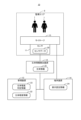
- FIG. 1 is a block diagram showing a configuration example of a detection system 10 according to the first embodiment.
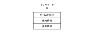
- FIG. 2 is a diagram showing a configuration example of sensor data 20 according to the first embodiment.
- FIG. 3 is a diagram showing a configuration example of the biometric information 21 according to the first embodiment.
- the detection system 10 includes a sensor 11, a biological information detection device 12, a management device 13, and a terminal device 14.
- the sensor 11, biological information detection device 12, management device 13, and terminal device 14 may be able to transmit and receive data or information through a predetermined communication network.
- the communication network may be wired or wireless.
- a plurality of sensors 11 may be arranged so that the entire monitoring area 8 can be monitored.
- the sensor 11 is a radar type sensor that emits radio waves in a predetermined frequency band and receives reflected waves reflected from an object (for example, a person 1) existing within the sensing range of the sensor 11.
- the sensor 11 compares the emitted radio wave and the received reflected wave to generate sensor data 20 shown in FIG. 2 .
- the sensor 11 may be a millimeter wave radar type sensor. Examples of millimeter wave radar systems include the FMCW (Frequency Modulated Continuous Wave) system and the step ICW (Interrupted Continuous Wave) system.
- time stamps, detection information, and signal information are associated with each other.
- the time stamp is information indicating the timing at which the sensor data 20 was obtained. Examples of timestamps include time information or frame numbers.
- the detection information includes, for example, information indicating a position in three-dimensional space where a reflected wave of a predetermined intensity or higher was obtained (hereinafter referred to as a reflection point), information indicating the distance from the sensor 11 to the reflection point, and information indicating the reflection point. Contains information indicating the reflection intensity at
- the signal information includes, for example, IQ data for each receiving antenna.
- the sensor data 20 is data that indicates the position, shape, and temporal changes of objects existing in the sensing range in three-dimensional space, and does not have the resolution of video data, so it It is not possible to identify the person, and the sensor 11 can obtain data while protecting the person's privacy.
- the sensor 11 transmits the generated sensor data 20 to the management device 13 and the terminal device 14.
- the biological information detection device 12 generates biological information 21 shown in FIG. 3 based on the sensor data 20 received from each sensor 11.
- a time stamp, detected person information, vital value information, and reliability are associated with each other.
- the time stamp is information indicating the timing at which the biometric information 21 was generated.
- An example of a timestamp is time information.
- the management device 13 sets the time when the biometric information 21 is generated as the time stamp.
- the detected person information is information regarding the detected person 1.
- the detected person information includes a person ID, a person position, and a person posture.
- the person ID is an ID for identifying the detected person 1.
- the person position indicates the position of the person indicated by the person ID in the three-dimensional space in the monitoring area 8.
- the person posture indicates the posture of the person 1 indicated by the person ID.
- the biological information detection device 12 identifies a person's position and posture based on the detection information of the sensor data 20.
- the vital value information is information regarding the vital value of the detected person 1, which is the active state.
- Examples of vital values include breathing rate, depth of breathing, heart rate, and blood pressure.
- the biological information detection device 12 calculates vital values (for example, breathing rate, depth of breathing, heart rate, blood pressure, etc.) of the detected person 1 based on temporal changes in the detection information of the sensor data 20.
- Reliability information is information indicating the reliability (likelihood) of vital value information.
- the biological information detection device 12 calculates the reliability of the calculated vital value information based on the detection information and signal information of the sensor data 20. Note that the reliability information can be generated based on the noise level ratio of the radar signal that is the calculation source of the vital value information or the comparison result of the reliability information of a plurality of different vital value information candidates.
- the biological information detection device 12 transmits the generated biological information 21 to the management device 13 and the terminal device 14.
- the management device 13 generates biological degree information 22 for each person 1 based on the biological information 21 received from the biological information detection device 12.
- the biological level information 22 is information indicating the degree (level) of vital values of the person 1, which is the active state.
- the management device 13 generates living body grade information 22 based on the living body grade determination information 23.
- the biological grade determination information 23 includes information for determining the grade from vital values. The user can operate the management device 13 to set the biological grade determination information 23. Note that details of the biological grade determination information will be described later.
- the management device 13 transmits the generated living body grade information 22 and living body grade determination information 23 to the terminal device 14.
- the terminal device 14 determines the behavior or state of the person 1 in the monitoring area 8 based on the biometric information 21 received from the biometric information detection device 12 and the biometric level information 22 and biometric level determination information 23 received from the management device 13. Estimate and display on the monitoring screen. At this time, the terminal device 14 determines the display mode of the behavior or state of the person 1 based on the display setting information 24.
- the display setting information 24 is information including settings for a display mode of a person's behavior or state. The user can operate the terminal device 14 to set the display setting information 24. Note that details of the display setting information 24 will be described later.
- the detection system 10 detects the biological condition of the person 1 using the radar type sensor 11 that senses the person using radio waves. Thereby, the biological condition of the person 1 can be detected while protecting the privacy of the person 1.
- FIG. 4 is a flowchart illustrating an example of a process for setting the living body degree determination information 23 and display setting information 24 by the detection system 10 according to the first embodiment.
- the management device 13 displays a usage scene selection screen. Note that a specific example of the selection screen will be described later.
- the user selects one usage scene from the selection screen (S11).
- the management device 13 reads and displays the default biological degree determination information 23 for the usage scene selected in step S11.
- the user sets the displayed biological condition determination information 23 (S12). Note that the details of how to set the living body level determination information 23 will be described later.
- the terminal device 14 displays the default display setting information 24 for the usage scene selected in step S11.
- the user sets the displayed display setting information 24 (S13). Note that the details of how to set the display setting information 24 will be described later.
- the management device 13 stores the usage scene selected in step S11 in the storage 1003 (see FIG. 25) in association with the biological degree determination information 23 set in step S12.
- the terminal device 14 associates the display setting information 24 set in step S13 with the usage scene selected in step S11 and stores it in the storage 1003 (S14).
- the appropriate living body level determination information 23 and display setting information 24 are associated and retained in the storage 1003 for each usage scene.
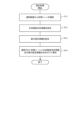
- FIG. 5 is a flowchart illustrating an example of monitoring processing of the monitoring area 8 by the detection system 10 according to the first embodiment.
- the terminal device 14 displays a usage scene selection screen. The user selects one usage scene from the selection screen (S21).
- the management device 13 acquires the biological degree determination information 23 associated with the usage scene selected in step S21 from the storage 1003.
- the terminal device 14 acquires the display setting information 24 associated with the usage scene selected in step S21 from the storage 1003 (S22). Thereby, the detection system 10 can perform monitoring processing using the living body degree determination information 23 and display setting information 24 that are appropriately set for the usage scene.
- the management device 13 uses the biological condition determination information 23 to generate biological condition information 22 from the biological information 21 received from the biological information detection device 12 (S23).
- the management device 13 transmits the generated biological condition information 22 to the terminal device 14.
- the terminal device 14 identifies the position and posture of the person 1 from the biometric information 21 received from the biometric information detection device 12 (S24).
- the terminal device 14 uses the display setting information 24 to estimate the person's behavior or state from the person's position and posture and the biological condition information 22 (S25).
- the terminal device 14 displays information indicating the estimated position, behavior, state, etc. of the person on the monitoring screen 400 (S26). Then, the detection system 10 returns the process to step S22.
- the user can intuitively monitor the position, behavior, or state of the person 1 within the monitoring area 8 (for example, an abnormal state related to the living body of the person 1) by viewing the monitoring screen.
- FIG. 6 is a diagram showing a selection screen 50A for the usage scene "watching over" according to the first embodiment.
- step S11 of FIG. 4 the management device 13 displays the usage scene selection screen shown in FIG. 6.
- the management device 13 displays a setting screen 100A of living body level determination information 23 for the usage scene "watch over” as shown below.
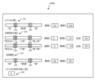
- FIG. 7 is a diagram illustrating an example of a setting screen 100A for the living body level determination information 23 for the usage scene "watching" according to the first embodiment.
- the setting screen 100A of the living body level determination information 23 for the usage scene "watching” includes a threshold setting area 101 for vital values, a threshold setting area 102 for the degree of change over time of vital values, and a setting area 102 for the depth of breathing. It is configured to include a threshold setting area 103 and a measurement number setting area 104.
- the user adjusts the threshold bar 120 included in the vital value threshold setting area 101 to set a threshold value for determining the biological level of the vital value based on the vital value.
- the biological degree of the level of vital values is referred to as the degree of vital level.
- the degree of vital level For example, when setting three levels of vital levels: “low,” “normal,” and “high,” the user sets threshold 1 to distinguish between “low” and “normal,” as shown in FIG. A threshold value 2 is set to distinguish between "normal” and “high”.
- the user may set the threshold to be lower (that is, stricter) for elderly people who are to be watched over.
- the set threshold value 1 and threshold value 2 may be displayed as numerical values.
- the number of vital levels is not limited to three levels, and may be two levels or four or more levels.
- the names of each stage of vital levels may be changeable by the user.
- each stage of the degree of vitality level may be read as a level of vitality level.
- the user adjusts the threshold bar 120 included in the threshold setting area 102 for the degree of change in vital values over time to set a threshold for determining the biological degree of the degree of change in vital values over time based on the degree of change in vital values over time.
- the biological degree regarding the degree of change in vital values over time includes a degree in an upward direction and a degree in a downward direction.
- the degree in the upward direction is referred to as the degree of change in vital vitals.
- the degree in the downward direction is referred to as the degree of vital decline change. For example, if three levels are set as the degree of change in vitals: "no change,” “increase,” and “rapidly increase,” as shown in FIG.
- a threshold value 2 is set to distinguish between "increase” and "rapid rise".
- the user may set the threshold to be lower (that is, stricter) for elderly people who are to be watched over.
- the set threshold value 1 and threshold value 2 may be displayed as numerical values.
- each stage of the degree of increase in vitals may be read as a level of increase in vitals.
- three levels of vital signs such as "no change,” “declining,” and “sudden decline,” as shown in FIG.
- a threshold value 2 that distinguishes between "downward” and "sudden descent” is set.
- the user may set the threshold to be lower (that is, stricter) for elderly people who are to be watched over.
- the set threshold value 1 and threshold value 2 may be displayed as numerical values. Note that each stage of the degree of decline in vitals may be read as a level of decline in vitals.
- the user adjusts the threshold bar 120 included in the breathing depth threshold setting area 103 to set a threshold for determining the degree of living body related to the breathing depth of the vital value from the breathing depth of the vital value. .
- the degree of the living body's vital values related to the depth of respiration is referred to as the degree of respiration depth.
- the degree of respiration depth For example, when setting three levels of breathing depth: "Shallow,” “Normal,” and “Deep,” the user sets threshold 1 to distinguish between “Shallow” and “Normal,” as shown in Figure 7.
- a threshold value 2 for distinguishing between "normal” and “deep” is set.
- the user may set the threshold to be lower (that is, stricter) for elderly people who are to be watched over.
- the set threshold value 1 and threshold value 2 may be displayed as numerical values. Note that each stage of breathing depth may be read as a breathing depth level.
- the user sets the maximum number of people to be measured in the measurement number setting area 104.
- the set maximum number of people will be referred to as the maximum number of people to be measured.
- the user may set "one person".
- the reliability of biometric information improves when the maximum number of people measured is reduced.
- the management device 13 generates biological degree determination information 23 including each threshold value set by the user and the maximum number of people to be measured, and stores it in the storage 1003 in association with the usage scene "watching over”. Thereby, in the monitoring process shown in FIG. 5, when the usage scene "watching over" is selected, the management device 13 can use the living body level determination information 23 appropriately set for the usage scene "watching over".
- FIG. 8 is a diagram showing a setting screen 200A of the display setting information 24 for the usage scene "watching" according to the first embodiment.
- the setting screen 200A of the display setting information 24 for the usage scene "watching" has as items an action or state name, a setting name, and a setting value.
- the action or state name indicates the name of the person's action or state.
- the setting name indicates the name of the setting associated with the action or state name.
- One or more setting names are associated with one action or state name.
- the setting value indicates the value associated with the setting name.
- One setting value is associated with one setting name.
- a plurality of setting values may be associated with one setting name.
- a set of a setting name and a setting value may be referred to as a display setting parameter.
- the setting value of the setting name "location condition” indicates the range of a person's position for determining the person's behavior as “sleeping.”
- the range may be defined by an X section and a Y section on the map.
- the user sets the range of "bedroom” on the map (floor plan of the residence) as the setting value of the setting name "location condition" associated with the action "sleeping.”
- the setting value of the setting name "posture condition” indicates the posture of the person for determining the person's behavior as “sleeping".
- One of the postures may be selected from a predetermined posture list. For example, the user selects "supine position” from a predetermined posture list as the setting value of the setting name "posture condition" associated with the action "sleeping.”
- the setting value of the setting name "biological degree condition” indicates the biological degree of the person and the correction amount of the biological degree for determining the person's behavior as "sleeping".
- the user may set a correction amount that lowers the default threshold of vital level level by a predetermined amount as a setting value of the setting name "biological level condition” associated with the action "sleeping". This eliminates the possibility that the terminal device 14 may erroneously determine the level of vitals as "low” even though the person's vitals are only slightly lower than normal because the person is sleeping. It can be suppressed.
- the setting value of the setting name "icon name” indicates the file name of the icon used when the behavior of the person is determined to be "sleeping".
- the terminal device 14 determines that the position of the person is within the range indicated by the setting value of the setting name "location condition” (for example, in the bedroom), and the person's posture is in the position indicated by the setting value of the setting name "posture condition”. If the person's vital level is "normal” corrected by the setting value of the setting name "biological condition”, the person's behavior is determined to be “sleeping”, and the person's behavior is determined to be “sleeping", ” Displays the icon of the file name indicated by the setting value. Note that details of the display method will be described later.
- the setting value of the setting name "location condition” indicates the range of a person's position for determining the person's behavior as “watching TV.”
- the range may be defined by an X section and a Y section on the map.
- the user sets the range of "living room” on the map (floor plan of the residence) as the setting value of the setting name "location condition” associated with the action "watching TV.”
- the setting value of the setting name "posture condition” indicates the posture of the person for determining the person's behavior as “watching TV.”
- One of the postures may be selected from a predetermined posture list. For example, the user selects “sitting position” from a predetermined posture list as the setting value of the setting name "posture condition” associated with the action "watching television.”
- the setting value of the setting name "biological degree condition” indicates the biological degree of the person and the correction amount of the biological degree for determining the person's behavior as "watching TV.” For example, a person watching television may have higher vital values than normal due to the influence of the content. Therefore, the user may set a correction amount that increases the default threshold of vital level level by a predetermined amount as a setting value of the setting name "biological level condition” associated with the action "watching television". As a result, it is possible to suppress the possibility that the terminal device 14 will erroneously judge the level of vitals as "high” even though the person's vitals are a little higher than usual because the person is watching TV. . However, it is not essential to associate the action name "Watching TV" with the setting name "Biological degree condition”.
- the setting value of the setting name "icon name” indicates the file name of the icon used when the person's behavior is determined to be “watching TV.”
- the terminal device 14 determines that the position of the person is within the range indicated by the setting value of "location condition” (for example, in the living room), the posture of the person is “sitting”, which is indicated by the setting value of "posture condition", If the person's vital level is "normal” as corrected by the setting value of the setting name "biological condition", the person's behavior is determined to be "watching TV” and the setting value of "icon name” indicates. Show file name icon. Note that details of the display method will be described later.
- the setting value of the setting name "location condition” indicates the range of the position of the person for determining the state of the person as "abnormal state". In FIG. 8, the entire range of the monitoring area 8 is set as the range for determining the abnormal state.
- the setting value of the setting name "posture condition” indicates the posture of the person for determining the state of the person as "abnormal state.”
- One of the postures may be selected from a predetermined posture list. For example, the user selects "supine position” from a predetermined posture list as the setting value of the setting name "posture condition" associated with the state "abnormal state.”
- the setting value of the setting name "vital height level condition” indicates the level of vitality level for determining a person's condition as an "abnormal state". For example, the user sets “high” and “low” as the setting values of the setting name "vital height level condition" associated with the state "abnormal state”.
- the setting value with the setting name "Vital rising/falling change degree condition” indicates the degree of vital rise change and the degree of vital decrease change for determining the person's condition as an "abnormal state.” For example, the user sets “sudden rise” and “sudden fall” as setting values for the setting name "vital rise/fall change degree condition” associated with the state "abnormal state”.
- the setting value of the setting name "icon name” indicates the file name of the icon to be used when the state of the person is determined to be "abnormal state”.
- the terminal device 14 determines that the person's position is in any of the monitoring areas 8 (for example, in a residence), the person's posture is the “supine position” indicated by the setting value of “posture condition”, and the person's The level of vitals is "high” or “low” as indicated by the setting value of "Vital height/lower level condition”, and the degree of increase or decrease of vitals of the person is indicated by the setting value of "Vital increase/lower change level condition”.
- the state of the person is determined to be "abnormal”
- an icon with the file name indicated by the setting value of the setting name "icon name” is displayed. Note that details of the display method will be described later.
- FIG. 9 is a diagram illustrating a setting screen 300A of biological degree correction setting information for the usage scene "watching" according to the first embodiment.
- the terminal device 14 displays a setting screen 300A for setting biological degree correction setting information shown in FIG.
- the setting screen 300A of biological degree correction setting information has a place name and a correction amount as items.
- the place name indicates the name of the place in the monitoring area 8.
- the place name is, for example, "living room”, “toilet”, “bathroom”, “bedroom”, etc.
- the amount of correction indicates the amount of correction of the living body degree determination information 23 when the person is located at the location indicated by the place name.
- the terminal device 14 determines the level of vitals of a person located in the toilet, taking into consideration the correction amount. This can suppress the possibility of erroneously determining the level of vitals as "high” even though the person's vitals are only slightly higher than normal because the person is in the tray.
- the terminal device 14 determines the level of vitals of a person located in the bathroom, taking into consideration the correction amount. Thereby, the terminal device 14 can suppress the possibility of erroneously determining the level of the vitals as "high” even though the vitals are slightly higher than usual because the person is taking a bath.
- FIG. 10 is a diagram illustrating an example of a monitoring screen 400A when a person is sleeping in a bedroom according to the first embodiment.
- the terminal device 14 displays a monitoring screen 400A, as shown in FIG.
- the monitoring screen 400A includes a map area 401, a posture area 402, a location area 403, and an action area 404.
- the terminal device 14 displays a floor plan of a residence in the monitoring area 8 as an example of a map in the map area 401.
- the terminal device 14 detects the posture of the person 1 based on the biometric information 21 received from the biometric information detection device 12 and displays the detected posture name in the posture area 402.
- the terminal device 14 detects the position of the person 1 based on the biometric information 21 received from the biometric information detection device 12.
- the terminal device 14 maps the detected position of the person on the floor plan and identifies the place name of the person 1.
- the terminal device 14 displays the specified place name in the place area 403.
- the terminal device 14 estimates the behavior of the person 1 based on the biometric information 21 received from the biometric information detection device 12, the biometric information 22 received from the management device 13, and the display setting information 24.
- the terminal device 14 displays the estimated action name of the person 1 in the action area 404.
- the terminal device 14 displays an icon 500 corresponding to the estimated behavior and an icon 501 corresponding to a living body at the specified location in the map area 401.
- the icon in this embodiment may be read as graphic information.
- the terminal device 14 displays “supine” in the posture area 402.
- the terminal device 14 displays "Bedroom” in the location area 403.
- the terminal device 14 estimates that the behavior of the person 1 is "sleeping" from the display setting information 24, it displays “sleeping” in the action area 404.
- the terminal device 14 estimates that the behavior of the person 1 is "sleeping” based on the living body level information 22 and the display setting information 24, the terminal device 14 selects a "bedroom” in the floor plan displayed in the map area 401. A "sleeping" icon 500 is displayed at the location.
- the terminal device 14 determines that the depth of breathing of the person 1 is "normal” and that the level of the person's vitals (for example, the level of heart rate) is “normal” based on the biological level information 22 and the display setting information 24. If it is determined that the level is "normal”, an icon 501 indicating the depth of breathing as "normal” and an icon 502 indicating the level of vitals (heart rate) as "normal” are displayed near the icon 500.
- the level of the person's vitals for example, the level of heart rate
- the user can intuitively confirm by looking at the monitoring screen 400A that the person 1 to be monitored who lives in the residence is currently sleeping in the bedroom and that his vitals are normal.
- FIG. 11 is a diagram showing an example of a monitoring screen 400B when a person according to Embodiment 1 is watching television in the living room.
- the terminal device 14 displays "sitting" in the posture area 402.
- the terminal device 14 displays "living room” in the location area 403.
- the terminal device 14 estimates that the behavior of the person 1 is "watching TV” based on the biological degree information 22 and the display setting information 24, it displays "Watching TV” in the action area 404.
- the terminal device 14 estimates that the location of the person 1 estimated from the biometric information 21 is "living room” and the action of the person 1 is "watching TV” based on the display setting information 24, An icon 503 of "Watching TV” is displayed in the "living room” location.
- the terminal device 14 determines that the depth of breathing of the person 1 is "normal” and that the level of the vitals of the person 1 (for example, the level of the heart rate) is "normal” based on the biological condition information 22 and the display setting information 24. If it is determined that the condition is "normal”, an icon 501 indicating the depth of breathing as "normal” and an icon 504 indicating the level of vitals (heart rate) as "normal” are displayed near the icon 503.
- the user can intuitively confirm by looking at the monitoring screen 400B that the person 1 to be monitored who lives in the residence is currently watching television in the living room and that his vitals are normal.
- FIG. 12 is a diagram showing an example of the monitoring screen 400C when a person is in an abnormal state in the bathroom according to the first embodiment.
- the terminal device 14 displays “supine” in the posture area 402.
- the terminal device 14 displays "bathroom” in the location area 403.
- the terminal device 14 determines that the state of the person 1 is "abnormal” based on the biological condition information 22 and the display setting information 24, the terminal device 14 displays the vital signs "abnormal” in the "bathroom” location of the floor plan.
- An icon 504 indicating . Note that although the action area 404 of the person 1 is not displayed, alert information such as "safety confirmation” and "emergency call” may be displayed.
- the user can look at the monitoring screen 400C and intuitively confirm that the person to be monitored who lives in the residence is currently experiencing vital abnormalities in the bathroom.
- FIG. 13 is a diagram showing a selection screen 50B for the usage scene "abnormality detection" according to the first embodiment.
- step S11 of FIG. 4 the management device 13 displays the usage scene selection screen 50B shown in FIG. 13.
- the management device 13 displays a setting screen 100B of biological grade determination information 23 for the usage scene "abnormality detection” as shown below.
- FIG. 14 is a diagram illustrating an example of a setting screen 100B for the biological grade determination information 23 for the usage scene "abnormality detection" according to the first embodiment.
- the setting screen 100B of the living body grade determination information 23 for the usage scene "abnormality detection” includes a threshold setting area 101 for vital values, a threshold setting area 102 for the degree of change over time of vital values, and a threshold for reliability. It is configured to include a setting area 105 and a measurement number setting area 104.
- the user adjusts the threshold bar 120 in the vital value threshold setting area 101 to set a threshold value corresponding to the height of the vital value.
- the user may set the threshold to be high (ie, relaxed) because the employee who is the target of abnormality detection is relatively healthy.
- the user adjusts the threshold bar 120 in the threshold value setting area 102 for the degree of change over time of vital values to set the threshold values for the degree of increase in vital values and the degree of decrease in vital values.
- the threshold may be low (ie, strict).
- the user adjusts the threshold bar 120 included in the reliability threshold setting area 105 to determine the threshold for determining the biological degree of reliability based on the reliability information included in the biometric information 21.
- the biological level regarding the level of reliability is referred to as the level of trust.
- the level of trust For example, when setting three levels of confidence: “low,” “normal,” and “high,” the user sets threshold 1 to distinguish between “low” and “normal,” as shown in FIG. A threshold value 2 for distinguishing between "normal” and “high” is set.
- a user may set the threshold to be high (that is, to be strict) because frequent false detections of an abnormal state even though the state is not present will hinder operations. You may.
- the set threshold value 1 and threshold value 2 may be displayed as numerical values. Note that the number of confidence levels is not limited to three levels, and may be two levels or four or more levels.
- each level of trust may be read as a trust level.
- the user sets the maximum number of people to be measured in the number of people to be measured setting area 104.
- the user may set the maximum number of people to be measured according to the number of employees working in the office.
- the management device 13 generates biological degree determination information 23 including each threshold value set by the user and the maximum number of people to be measured, and stores it in the storage 1003 in association with the usage scene "abnormality detection". Thereby, in the monitoring process shown in FIG. 5, when the usage scene "abnormality detection" is selected, the management device 13 can use the biological degree determination information 23 appropriately set for "abnormality detection".
- FIG. 15 is a diagram showing a setting screen of the display setting information 24 for the usage scene "abnormality detection" according to the first embodiment.
- the setting screen of the display setting information 24 for the usage scene "abnormality detection" has, as shown in FIG. 8, an action or state name, a setting name, and a setting value as items.
- the setting value of the setting name "location condition” indicates the range of a person's position for determining the person's behavior as “working".
- the range may be defined by an X section and a Y section on the map.
- the user sets the range of "desk” on a map (for example, a floor plan of an office) as a setting value of the setting name "location condition" associated with the action "working".
- the setting value of the setting name "posture condition” indicates the posture of the person for determining the person's behavior as "working".
- One of the postures may be selected from a predetermined posture list. For example, the user selects "sitting position” from a predetermined posture list as the setting value of the setting name "posture condition” associated with the action "working".
- the setting value of the setting name "living condition” indicates the living body level of the person and the correction amount of the living body level for determining the person's behavior as "working".
- a person working is concentrating, so their vital values tend to be lower than normal. Therefore, the user may set a correction amount that lowers the default threshold of vital level level by a predetermined amount as a setting value of the setting name "biological level condition” associated with the action "working". This eliminates the possibility that the management device 13 may incorrectly determine the level of vitals as "low” even though the person's vitals are only slightly lower than normal because the person is working. It can be suppressed. However, it is not essential to associate the action name "Working" with the setting name "Living condition”.
- the setting value of the setting name "icon name” indicates the file name of the icon used when the person's behavior is determined to be "working”.
- the terminal device 14 determines that the person's position is within the range indicated by the setting value of "place condition” (for example, at a desk), the person's posture is “sitting position” indicated by the setting value of "posture condition”, and the person's vitals are If the height level is "normal” corrected by the setting value of the setting name "Biological level condition", the behavior of the person is determined to be "working” and the file name indicated by the setting value of the setting name "icon name” Display the icon. Note that details of the display method will be described later.
- the setting value of the setting name "reliability level condition” indicates the reliability level for determining the state of person 1 as an "abnormal state". For example, the user sets "high” as the setting value of the setting name "reliability level condition” associated with the state "abnormal state”.
- the possibility of biological abnormalities occurring is lower than that of elderly people, and false positives frequently occur with low reliability, hindering operations. This is because there is a possibility that
- the terminal device 14 determines that the position of person 1 is within the range indicated by the setting value of "location condition", the posture of person 1 is the “supine position” indicated by the setting value of "posture condition", and The level of vitals is “high” or “low” as indicated by the set value of "vital height/lower level condition", and the degree of increase or decrease in vitals of person 1 is the set value of "vital increase/lower change level condition” is a “sudden rise” or “sudden decline” and the trust level of the person 1 is "high” as indicated by the setting value of the "trust level condition", the state of the person 1 is determined to be an "abnormal state", Displays the icon with the file name indicated by the setting value of the setting name "icon name”. Note that details of the display method will be described later.
- FIG. 16 is a diagram showing a setting screen of biological degree correction setting information for the usage scene "abnormality detection" according to the first embodiment.
- the terminal device 14 displays a setting screen 300B for setting biological degree correction setting information shown in FIG. 16.
- the setting screen 300B for biological degree correction setting information has a place name and a correction amount as items.
- the place name may be, for example, "toilet", “aisle”, etc.
- the terminal device 14 determines the level of vitals of the person 1 located in the toilet, taking into consideration the correction amount. Thereby, it is possible to suppress the possibility of erroneously determining the level of vitals as "high” even though the vitals are slightly higher than usual because the person 1 is in the tray.
- the terminal device 14 determines the level of vitals of the person 1 located in the passage, taking into consideration the correction amount. As a result, the terminal device 14 may erroneously determine the level of the person's vitals as "high” even though the vitals are only slightly higher than normal because the person is moving through the aisle. You can suppress your sexuality.
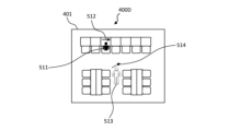
- FIG. 17 is a diagram illustrating an example of a monitoring screen 400D when two people are in an office according to the first embodiment.
- the terminal device 14 displays a monitoring screen 400D, as shown in FIG. 17.
- the monitoring screen 400D includes a map area 401.
- the terminal device 14 displays a floor plan of the office, which is the monitoring area 8, as an example of a map in the map area 401.
- the terminal device 14 estimates that the behavior of person A is "working” from the display setting information 24, the terminal device 14 places an icon “working” at the location of person A in the floor plan displayed in the map area 401. 511 is displayed. In addition, the terminal device 14 displays the icon 511 with, for example, a solid line so that it can be seen that the reliability level is "high”. In addition, the terminal device 14 displays an arrow icon (horizontal arrow icon 512 in FIG. 17) indicating that the degree of increase/decrease in vitals (heart rate) is "normal” near the icon 511.
- the terminal device 14 when the terminal device 14 estimates that the behavior of person B is "moving" from the display setting information 24, the terminal device 14 indicates “moving” at the position of person B in the floor plan displayed in the map area 401.
- An icon 513 is displayed.
- the terminal device 14 displays the icon 513 with, for example, a broken line so that it can be seen that the reliability level is "low”.
- the terminal device 14 displays, near the icon 513, an arrow icon (in FIG. 17, a diagonally upward arrow icon 514) indicating that the degree of increase/decrease in vital signs (heart rate) is "rapidly”. .
- the user can intuitively confirm by looking at the monitoring screen 400D that Person A working in the office is working, his vitals are normal, and the reliability of the vitals is high. Further, the user can intuitively confirm by looking at the monitoring screen 400D that although Person B is moving and the change in vitals is rapidly increasing, the reliability of the vitals is low.
- FIG. 18 is a diagram showing an example of the monitoring screen 400E when there is a person in an abnormal state in the office according to the first embodiment.
- the terminal device 14 estimates that the state of person C is in an "abnormal state" based on the display setting information 24, the terminal device 14 places an icon indicating "abnormal state” at the position of the person in the floor plan displayed in the map area 401. 515 is displayed. In addition, the terminal device 14 displays the icon 515 as a solid line, for example, so that it can be seen that the reliability level is "high”. In addition, the terminal device 14 displays an icon 516 near the icon 515 indicating that the vitals are in an "abnormal state.”
- the terminal device 14 may output an alert indicating that the person 1 with a biological abnormality has occurred (for example, displaying a character string or issuing a sound regarding safety confirmation).
- FIG. 19 is a diagram showing a configuration example of the detection system 10 for content viewing reaction detection according to the first embodiment.
- the detection system 10 further includes a signage 15 that displays content.
- the signage 15 is a so-called digital signage device, and includes, for example, a liquid crystal display. Further, the signage 15 may be connected to the terminal device 14 through a predetermined communication network. The terminal device 14 may be able to control content displayed on the signage 15.
- the sensor 11 is attached to the back surface of the signage 15, for example, and senses a person present in front of the signage 15.
- the sensors 11 may be arranged in any manner, and a plurality of sensors 11 may be arranged.
- FIG. 20 is a diagram showing a selection screen 50C of the usage scene "content viewing reaction detection" according to the first embodiment.
- step S11 of FIG. 4 the management device 13 displays the usage scene selection screen 50C shown in FIG. 20.
- the management device 13 displays a setting screen 100C of living body degree determination information 23 for the usage scene "content viewing reaction detection” shown below.
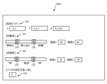
- FIG. 21 is a diagram illustrating an example of the setting screen 100C of the biological grade determination information 23 for the usage scene "content viewing reaction detection" according to the first embodiment.
- the setting screen 100C of the living body level determination information 23 for the usage scene "content viewing reaction detection” includes a monitoring area setting area 106, an excitement level threshold setting area 107, a reliability threshold setting area 105, It also includes a measurement number setting area 104.
- the user sets the monitoring area 8 for content viewing reaction detection in the monitoring area setting area 106.
- the user sets the X section, Y section, and Z section so that the monitoring area 8 is in front of the signage 15. Further, the user may set the monitoring area 8 according to the size of the signage 15.
- the user adjusts the threshold bar 120 included in the threshold setting area 107 for the degree of excitement to determine the threshold for determining the biological degree of the level of excitement based on the degree of excitement.
- the degree of a living organism's degree of excitement is referred to as the degree of excitement.
- the degree of excitement may be calculated based on the magnitude and time change of vital values (for example, heart rate and/or respiratory rate). For example, when setting three levels of excitement: “indifferent,” “interested,” and “excited,” the user sets threshold 1 to distinguish between “indifferent” and "interested,” as shown in FIG.
- a threshold value 2 is set to distinguish between "interested” and "excited.” For example, the user may set the threshold to be low (that is, relaxed) so that even some degree of interest of the person 1 can be detected.
- the set threshold value 1 and threshold value 2 may be displayed as numerical values. Note that the number of levels of excitement is not limited to three levels, but may be two levels or four or more levels. Further, the name of each level of excitement may be changeable by the user. Note that each stage of excitement may be read as an excitement level.
- the user adjusts the threshold bar 120 included in the reliability threshold setting area 105 to determine the threshold for determining the reliability level from the reliability level. For example, in content reaction detection, even if the reliability is low, there is no problem in operation, so the user may set the threshold to be low (that is, relaxed).
- the user sets the maximum number of people to be measured in the number of people to be measured setting area 104.
- the user may set the maximum number of people that the system can handle.
- the management device 13 generates biological degree determination information 23 including the set monitoring area 8, each threshold value, and the maximum number of people to be measured, and stores it in the storage 1003 in association with the usage scene "content viewing reaction detection". As a result, in the monitoring process shown in FIG. 5, when the usage scene "content viewing reaction detection" is selected, the management device 13 uses the biological grade determination information 23 appropriately set for "content viewing reaction detection". can.
- FIG. 22 is a diagram showing a setting screen 200C of the display setting information 24 for the usage scene "content viewing reaction detection" according to the first embodiment.
- the setting screen 200C of the display setting information 24 for the usage scene "content viewing reaction detection" has an action or state name, a setting name, and a setting value as items, similar to FIG. 8. .
- the setting value of the setting name “posture condition” indicates the posture of the person 1 for determining the behavior of the person 1 as “walking”.
- One of the postures may be selected from a predetermined posture list. For example, the user selects "standing” from a predetermined posture list as the setting value of the setting name "posture condition” associated with the action "walking.”
- the setting value of the setting name "operation condition” indicates the action of the person 1 for determining the action of the person 1 as "walking".
- One of the operations may be selected from a predetermined operation list. For example, the user selects "move” from a predetermined action list as the setting value of the setting name "operating condition" associated with the action "walking".
- the setting value of the setting name "biological degree condition” indicates the biological degree of the person 1 and the correction amount of the biological degree for determining the behavior of the person 1 as "walking".
- the vital values of a walking person tend to be higher than normal. Therefore, the user may set a correction amount that increases the default excitement level threshold by a predetermined amount as a setting value of the setting name "biological level condition” associated with the action "walking".
- the terminal device 14 incorrectly determines the degree of excitement as "interested” or "excited” even though the person 1 is walking and his/her vital values are higher than normal. The possibility of being lost can be suppressed.
- the setting value of the setting name "icon name” indicates the file name of the icon used when the behavior of the person 1 is determined to be "walking.”
- the terminal device 14 determines that the posture of the person 1 is "standing” indicated by the setting value of the setting name "posture condition", and the motion of the person 1 is “moving” indicated by the setting value of the setting name “movement”. , if the degree of excitement of person 1 is "indifferent” corrected by the setting value of the setting name "biological degree condition", the behavior of the person 1 is determined to be "walking", and the setting name of "icon name” is determined. Displays the icon of the file name indicated by the value. Note that details of the display method will be described later.
- the setting value of the setting name "posture condition” indicates the posture of the person 1 for determining the behavior of the person 1 as "still".
- One of the postures may be selected from a predetermined posture list. For example, the user selects "standing” from a predetermined posture list as the setting value of the setting name "posture condition" associated with the action "resting".
- the setting value of the setting name "operation condition” indicates the action of the person 1 for determining the action of the person 1 as "still".
- One of the operations may be selected from a predetermined operation list. For example, the user selects "stop” from a predetermined action list as the setting value of the setting name "operating condition" associated with the action "resting".
- the setting value of the setting name "Living Condition” indicates the living body level of the person 1 and the correction amount of the living body level for determining the behavior of the person 1 as being "at rest.”
- the user may set a correction amount that lowers the default excitement level threshold by a predetermined amount as a setting value of the setting name "biological level condition” associated with the action "resting”. This eliminates the possibility that the terminal device 14 may erroneously determine the degree of excitement as "interested” even though the person 1 is stationary and his/her vital values are lower than normal. It can be suppressed.
- the setting value of the setting name "icon name” indicates the file name of the icon to be used when the behavior of person 1 is determined to be "still”.
- the terminal device 14 determines that the posture of the person 1 is "standing” indicated by the setting value of the setting name "posture condition", and the motion of the person 1 is “stop” indicated by the setting value of the setting name "movement”. , if the degree of excitement of person 1 is "indifferent” corrected by the setting value of the setting name "biological degree condition", the behavior of the person 1 is determined to be "resting”, and the setting name of "icon name” is determined. Displays the icon of the file name indicated by the value. Note that details of the display method will be described later.
- the setting value of the setting name “excitement level condition” indicates the degree of excitement of the person for determining the state of the person 1 as “attention” to the content displayed on the signage 15. For example, the user sets "interested” and “excited” as setting values for the setting name "excitement level condition” associated with the state "attention”.
- the setting value of the setting name "face orientation condition” indicates the direction of the person's face for determining the state of person 1 as "attention". For example, the user sets the range of angles of the face when facing in the front direction of the signage 15 as a setting for the setting name "face orientation condition” associated with the state "attention". Note that the direction of the person's face may be detected based on the biometric information 21.
- the setting value of the setting name "icon color” indicates the color of the icon to be used when the state of person 1 is determined to be "attention”.
- the terminal device 14 determines that the degree of excitement of the person 1 is "interested” or “excited” indicated by the setting value of the setting name "excitement level condition", and the direction of the face of the person 1 is the setting value of the setting name "face orientation condition”. ”, the state of the person 1 is determined to be “attention”, and the icon is displayed in the color indicated by the setting value of the setting name “icon color”. Note that details of the display method will be described later.
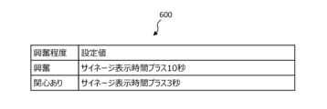
- FIG. 23 is a diagram illustrating an example of signage setting information 600 according to the first embodiment.
- the signage setting information 600 includes settings for changing the content display on the signage 15 according to the detection result of the content viewing reaction.
- the signage setting information 600 has as items the degree of excitement and a setting value.
- the user increases the display time of the content being displayed on the signage 15 by 10 seconds as a setting value for the excitement level "excitement”.
- Map settings the terminal device 14 increases the display time of the content being displayed on the signage 15 by 10 seconds when the person 1 with the excitement level "excited" is present in the monitoring area 8.
- the user increases the display time of the content currently displayed on the signage 15 by 3 seconds as a setting value for the excitement level "interested". Map the settings that you want to use.
- the terminal device 14 increases the display time of the content being displayed on the signage 15 by 3 seconds if the person 1 with the level of excitement "interested" is present in the monitoring area 8.
- FIG. 24 is a diagram showing an example of a monitoring screen 400F for the administrator of the signage 15 according to the first embodiment.
- the monitoring screen 400F includes a content area 421, a person area 422, an attention area 423, and a graph area 424.
- the terminal device 14 displays the content being displayed on the signage 15 in the content area 421.
- the terminal device 14 displays the behavior or status of each detected person in the person area 422 as an icon. As shown in FIG. 24, the terminal device 14 may display icons for the number of detected persons. For example, if the detected behavior of the person is "walking", the terminal device 14 displays a walking icon 521. For example, if the detected person's behavior is "resting", the terminal device 14 displays the "resting" icon 522. For example, when the degree of excitement of the detected person is "excitement", an icon 523 of a color (for example, red) corresponding to "excitement” is displayed. For example, if the level of excitement of the detected person is "interested", an icon (not shown) in a color (for example, orange) corresponding to "interested” is displayed.
- a color for example, orange
- the terminal device 14 displays the degree of interest in the degree of interest area 423.
- the terminal device 14 may calculate the degree of attention based on the proportion of the detected persons whose status is determined to be "attention" in the display setting information 24.
- the terminal device 14 displays, in the graph area 424, a graph GR showing changes in attention level over time.
- the horizontal axis indicates time and the vertical axis indicates the degree of attention.
- the terminal device 14 may update the graph GR at any time.
- the terminal device 14 may generate content attention level information and hold it in the storage 1003 by associating the displayed contents of the content with the attention level when the content was being displayed. Thereby, the administrator of the signage 15 can use the content attention degree information to later analyze which content among the contents displayed on the signage 15 has attracted how much attention.
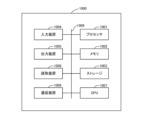
- FIG. 25 is a diagram showing the hardware configuration of a computer that implements the functions of each device according to the present disclosure using a computer program.
- the computer 1000 includes a processor 1001, a memory 1002, a storage 1003, an input device 1004, an output device 1005, a communication device 1006, a GPU (Graphics Processing Unit) 1007, a reading device 1008, and a bus 1009.
- a processor 1001 a memory 1002, a storage 1003, an input device 1004, an output device 1005, a communication device 1006, a GPU (Graphics Processing Unit) 1007, a reading device 1008, and a bus 1009.
- a processor 1001, a memory 1002, a storage 1003, an input device 1004, an output device 1005, a communication device 1006, a GPU 1007, and a reading device 1008 are connected to a bus 1009 and can send and receive data bidirectionally via the bus 1009.
- the processor 1001 is a device that executes a computer program stored in the memory 1002 and implements the functional blocks described above.
- Examples of the processor 1001 include a CPU (Central Processing Unit), MPU (Micro Processing Unit), controller, LSI (Large Scale Integration), ASIC (Application Specific Integrated Circuit), PLD (Programmable Logic Device), and FPGA (Field-Programmable Gate). Array).
- the memory 1002 is a device that is composed of a volatile storage medium and stores computer programs and data handled by the computer 1000. However, at least a portion of memory 1002 may be configured with a nonvolatile storage medium.
- the storage 1003 is a device that is composed of a non-volatile storage medium and stores computer programs and data handled by the computer 1000.
- An example of the storage 1003 is an HDD (Hard Disk Drive) or an SSD (Solid State Drive).
- the input device 1004 is a device that accepts data input to the processor 1001. Examples of input devices 1004 include a keyboard, mouse, touch pad, or microphone.
- the output device 1005 is a device that outputs data generated by the processor 1001. Examples of the output device 1005 include a display or a speaker.
- the communication device 1006 is a device that transmits and receives data to and from other devices via a communication network.
- the communication device 1006 may include a transmitter that transmits data and a receiver that receives data.
- the communication device 1006 may support either wired communication or wireless communication.
- An example of wired communication is Ethernet (registered trademark).
- Examples of wireless communication include IEEE802.11, Wi-Fi (registered trademark), Bluetooth (registered trademark), LTE, 4G, and 5G.
- the GPU 1007 is a device that processes image depiction at high speed. Note that the GPU 1007 may be used for AI (artificial intelligence) processing (for example, deep learning).
- AI artificial intelligence
- deep learning deep learning
- the reading device 1008 is a device that reads data from a recording medium such as a DVD-ROM (Digital Versatile Disk Read Only Memory) or a USB (Universal Serial Bus) memory.
- a recording medium such as a DVD-ROM (Digital Versatile Disk Read Only Memory) or a USB (Universal Serial Bus) memory.
- the technology of the present disclosure includes a system that detects the state of a person's biological body using a radar-based sensor; It is useful for methods, programs, etc.
Landscapes
- Health & Medical Sciences (AREA)
- Life Sciences & Earth Sciences (AREA)
- Physics & Mathematics (AREA)
- Molecular Biology (AREA)
- Animal Behavior & Ethology (AREA)
- General Physics & Mathematics (AREA)
- Biophysics (AREA)
- Pathology (AREA)
- Engineering & Computer Science (AREA)
- Biomedical Technology (AREA)
- Heart & Thoracic Surgery (AREA)
- Medical Informatics (AREA)
- Emergency Management (AREA)
- Surgery (AREA)
- Business, Economics & Management (AREA)
- General Health & Medical Sciences (AREA)
- Public Health (AREA)
- Veterinary Medicine (AREA)
- Oral & Maxillofacial Surgery (AREA)
- Physiology (AREA)
- Dentistry (AREA)
- Alarm Systems (AREA)
- Measurement Of The Respiration, Hearing Ability, Form, And Blood Characteristics Of Living Organisms (AREA)
- Measuring And Recording Apparatus For Diagnosis (AREA)
- Emergency Alarm Devices (AREA)
Applications Claiming Priority (2)
| Application Number | Priority Date | Filing Date | Title |
|---|---|---|---|
| JP2022-036398 | 2022-03-09 | ||
| JP2022036398A JP2023131562A (ja) | 2022-03-09 | 2022-03-09 | 検出システム、検出方法、及び、検出プログラム |
Publications (1)
| Publication Number | Publication Date |
|---|---|
| WO2023171348A1 true WO2023171348A1 (ja) | 2023-09-14 |
Family
ID=87936884
Family Applications (1)
| Application Number | Title | Priority Date | Filing Date |
|---|---|---|---|
| PCT/JP2023/006087 Ceased WO2023171348A1 (ja) | 2022-03-09 | 2023-02-20 | 検出システム、検出方法、及び、検出プログラム |
Country Status (2)
| Country | Link |
|---|---|
| JP (1) | JP2023131562A (https=) |
| WO (1) | WO2023171348A1 (https=) |
Citations (5)
| Publication number | Priority date | Publication date | Assignee | Title |
|---|---|---|---|---|
| JPH04266739A (ja) * | 1991-02-21 | 1992-09-22 | Nec San-Ei Instr Co Ltd | 患者監視装置 |
| JP2011519288A (ja) * | 2008-04-03 | 2011-07-07 | カイ メディカル、 インコーポレイテッド | 非接触の生理的運動センサおよびその使用方法 |
| JP2012075861A (ja) * | 2010-09-09 | 2012-04-19 | Citizen Holdings Co Ltd | 安否監視装置 |
| JP2016085577A (ja) * | 2014-10-24 | 2016-05-19 | 吉田 一雄 | 自殺抑制システム |
| WO2020259653A1 (zh) * | 2019-06-28 | 2020-12-30 | 华为技术有限公司 | 一种基于跌倒检测的呼救方法及电子设备 |
-
2022
- 2022-03-09 JP JP2022036398A patent/JP2023131562A/ja active Pending
-
2023
- 2023-02-20 WO PCT/JP2023/006087 patent/WO2023171348A1/ja not_active Ceased
Patent Citations (5)
| Publication number | Priority date | Publication date | Assignee | Title |
|---|---|---|---|---|
| JPH04266739A (ja) * | 1991-02-21 | 1992-09-22 | Nec San-Ei Instr Co Ltd | 患者監視装置 |
| JP2011519288A (ja) * | 2008-04-03 | 2011-07-07 | カイ メディカル、 インコーポレイテッド | 非接触の生理的運動センサおよびその使用方法 |
| JP2012075861A (ja) * | 2010-09-09 | 2012-04-19 | Citizen Holdings Co Ltd | 安否監視装置 |
| JP2016085577A (ja) * | 2014-10-24 | 2016-05-19 | 吉田 一雄 | 自殺抑制システム |
| WO2020259653A1 (zh) * | 2019-06-28 | 2020-12-30 | 华为技术有限公司 | 一种基于跌倒检测的呼救方法及电子设备 |
Also Published As
| Publication number | Publication date |
|---|---|
| JP2023131562A (ja) | 2023-09-22 |
Similar Documents
| Publication | Publication Date | Title |
|---|---|---|
| CN109416943B (zh) | 监测装置、用于动态调整监测装置的警报极限设置的方法 | |
| US9766370B2 (en) | Wrist-detection algorithm | |
| KR102408312B1 (ko) | 바이탈 사인 센서 기반의 응급상황 모니터링 시스템 | |
| US20180333050A1 (en) | Multiple independent audio spheres for patient monitor | |
| JP2018186940A (ja) | ベッドシステム | |
| JPWO2016199749A1 (ja) | 画像処理システム、画像処理装置、画像処理方法、および画像処理プログラム | |
| CN111432715B (zh) | 闭环报警管理 | |
| CN107735014B (zh) | 利用分析优化监视装置的患者警报设定 | |
| CN111538030A (zh) | 检测人类活动的方法、系统和非暂态计算机可读介质 | |
| WO2023171349A1 (ja) | 検出システム、検出方法、及び、検出プログラム | |
| WO2023176413A1 (ja) | 検出システム、検出方法、及び、検出プログラム | |
| US10839668B2 (en) | Alarm information processing apparatus and control program for alarm information processing apparatus | |
| KR102537316B1 (ko) | 활동센서 기반의 상황 감시 시스템 | |
| WO2023171348A1 (ja) | 検出システム、検出方法、及び、検出プログラム | |
| WO2017134681A2 (en) | Sleep monitoring and tracking system and method thereof | |
| US11004322B2 (en) | Systems and methods for adjusting medical device behavior | |
| CN114983379A (zh) | 基于毫米波雷达的使用者监测方法和计算机设备 | |
| KR20240072435A (ko) | 생활 안전 모니터링에 따른 알림 제공 방법 및 디바이스 | |
| KR102881678B1 (ko) | 레이더 센서를 이용한 이상징후 감지영역 다중설정 및 모니터링 방법 및 시스템 | |
| CN114255566A (zh) | 一种监测人员生命状态的居家看护方法及系统 | |
| JP7596696B2 (ja) | 生体情報監視装置、生体情報監視システム及びプログラム | |
| JP2023137778A (ja) | 検出システム、検出方法、及び、検出プログラム | |
| JP2023137776A (ja) | 検出システム、検出方法、及び、検出プログラム | |
| JPWO2020136592A1 (ja) | 情報処理装置、情報処理方法、情報処理プログラム、および情報処理システム | |
| KR20260060545A (ko) | 실시간 건강 이상 감지를 위한 웨어러블 장치 및 그 방법 |
Legal Events
| Date | Code | Title | Description |
|---|---|---|---|
| 121 | Ep: the epo has been informed by wipo that ep was designated in this application |
Ref document number: 23766527 Country of ref document: EP Kind code of ref document: A1 |
|
| NENP | Non-entry into the national phase |
Ref country code: DE |
|
| 122 | Ep: pct application non-entry in european phase |
Ref document number: 23766527 Country of ref document: EP Kind code of ref document: A1 |