WO2023170993A1 - 車載カメラシステム、および、車載カメラの露光条件決定方法 - Google Patents
車載カメラシステム、および、車載カメラの露光条件決定方法 Download PDFInfo
- Publication number
- WO2023170993A1 WO2023170993A1 PCT/JP2022/029253 JP2022029253W WO2023170993A1 WO 2023170993 A1 WO2023170993 A1 WO 2023170993A1 JP 2022029253 W JP2022029253 W JP 2022029253W WO 2023170993 A1 WO2023170993 A1 WO 2023170993A1
- Authority
- WO
- WIPO (PCT)
- Prior art keywords
- vehicle
- exposure condition
- exposure
- camera
- cameras
- Prior art date
- Legal status (The legal status is an assumption and is not a legal conclusion. Google has not performed a legal analysis and makes no representation as to the accuracy of the status listed.)
- Ceased
Links
Images



Classifications
-
- H—ELECTRICITY
- H04—ELECTRIC COMMUNICATION TECHNIQUE
- H04N—PICTORIAL COMMUNICATION, e.g. TELEVISION
- H04N23/00—Cameras or camera modules comprising electronic image sensors; Control thereof
- H04N23/70—Circuitry for compensating brightness variation in the scene
- H04N23/73—Circuitry for compensating brightness variation in the scene by influencing the exposure time
-
- G—PHYSICS
- G06—COMPUTING OR CALCULATING; COUNTING
- G06V—IMAGE OR VIDEO RECOGNITION OR UNDERSTANDING
- G06V10/00—Arrangements for image or video recognition or understanding
- G06V10/10—Image acquisition
- G06V10/12—Details of acquisition arrangements; Constructional details thereof
- G06V10/14—Optical characteristics of the device performing the acquisition or on the illumination arrangements
- G06V10/141—Control of illumination
-
- G—PHYSICS
- G06—COMPUTING OR CALCULATING; COUNTING
- G06V—IMAGE OR VIDEO RECOGNITION OR UNDERSTANDING
- G06V20/00—Scenes; Scene-specific elements
- G06V20/50—Context or environment of the image
- G06V20/56—Context or environment of the image exterior to a vehicle by using sensors mounted on the vehicle
- G06V20/58—Recognition of moving objects or obstacles, e.g. vehicles or pedestrians; Recognition of traffic objects, e.g. traffic signs, traffic lights or roads
-
- H—ELECTRICITY
- H04—ELECTRIC COMMUNICATION TECHNIQUE
- H04N—PICTORIAL COMMUNICATION, e.g. TELEVISION
- H04N13/00—Stereoscopic video systems; Multi-view video systems; Details thereof
- H04N13/20—Image signal generators
- H04N13/204—Image signal generators using stereoscopic image cameras
-
- H—ELECTRICITY
- H04—ELECTRIC COMMUNICATION TECHNIQUE
- H04N—PICTORIAL COMMUNICATION, e.g. TELEVISION
- H04N13/00—Stereoscopic video systems; Multi-view video systems; Details thereof
- H04N13/20—Image signal generators
- H04N13/204—Image signal generators using stereoscopic image cameras
- H04N13/239—Image signal generators using stereoscopic image cameras using two two-dimensional [2D] image sensors having a relative position equal to or related to the interocular distance
-
- H—ELECTRICITY
- H04—ELECTRIC COMMUNICATION TECHNIQUE
- H04N—PICTORIAL COMMUNICATION, e.g. TELEVISION
- H04N13/00—Stereoscopic video systems; Multi-view video systems; Details thereof
- H04N13/20—Image signal generators
- H04N13/296—Synchronisation thereof; Control thereof
-
- H—ELECTRICITY
- H04—ELECTRIC COMMUNICATION TECHNIQUE
- H04N—PICTORIAL COMMUNICATION, e.g. TELEVISION
- H04N13/00—Stereoscopic video systems; Multi-view video systems; Details thereof
- H04N2013/0074—Stereoscopic image analysis
- H04N2013/0081—Depth or disparity estimation from stereoscopic image signals
Definitions
- the present invention relates to an in-vehicle camera system that recognizes the outside world of a vehicle by using a plurality of cameras, and a method for determining exposure conditions for an in-vehicle camera.
- Vehicle control technologies such as ACC (Adaptive Cruise Control), AEBS (Advanced Emergency Braking System), and LKAS (Lane Keeping Assist System) are known as technical elements of driving support systems and automatic driving systems.
- the system uses images captured by an on-vehicle camera to detect targets around the vehicle (e.g., other vehicles, pedestrians, cyclists, traffic lights, traffic signs, white lines, obstacles).
- targets around the vehicle e.g., other vehicles, pedestrians, cyclists, traffic lights, traffic signs, white lines, obstacles.
- By constantly recognizing and tracking vehicles e.g.), it is known that the vehicle can follow the vehicle in front, apply emergency brakes, or control steering to avoid drifting out of the driving lane.
- vehicles that enable automatic parking by arranging multiple cameras to monitor not only the front and rear of the vehicle but also the sides are becoming popular.
- Patent Document 1 is known as a conventional technique for controlling the exposure time of a vehicle-mounted camera.
- the abstract of the same document states that the problem is ⁇ capturing and displaying images of the surroundings of the vehicle while taking into consideration the driving conditions of the vehicle,'' and as a solution, ⁇ The on-vehicle camera control device and a camera control means that changes the exposure time of the vehicle-mounted camera according to the vehicle speed acquired by the vehicle speed acquisition means.
- paragraph 0036 of the same document states, "When the vehicle is moving at high speed, an image of the surroundings of the vehicle can be displayed in real time, although the image is not clear.”
- the exposure time control in Patent Document 1 uniformly changes the exposure time of the in-vehicle camera according to the vehicle speed in order to display images around the host vehicle in real time. had the problem of not being able to obtain clear images when moving at high speed. Therefore, if the blurred image captured by the technology of Patent Document 1 is used, targets around the own vehicle cannot be accurately recognized, and vehicle control such as ACC, AEBS, LKAS, etc. may not be properly realized. was there.
- the in-vehicle camera system of the present invention includes a plurality of cameras arranged in the own vehicle so that at least a portion of the field of view has overlapping stereoscopic viewing areas, and based on the behavior of the own vehicle, a movement amount calculation unit that calculates a movement amount of a feature point in the stereo viewing area imaged by the plurality of cameras; and a first exposure that determines a first exposure condition of the plurality of cameras so that the movement amount is equal to or less than a threshold value.
- An in-vehicle camera system includes: an exposure control unit that switches an exposure condition to the first exposure condition or the second exposure condition.
- the in-vehicle camera system and the in-vehicle camera exposure condition determination method of the present invention by time-sharingly switching exposure control for distance measurement and exposure control for target object recognition, ACC, AEBS, LKAS It is possible to obtain accurate three-dimensional information and target object recognition information required for vehicle control, etc., without being affected by vehicle speed.
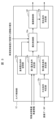
- FIG. 1 is a functional block diagram of an in-vehicle camera system according to an embodiment.
- FIG. 3 is a top view showing the relationship between the viewing area and the stereo viewing area of each camera.
- FIG. 2 is a functional block diagram of the camera control section in FIG. 1.
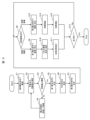
- FIG. 1 is a processing flowchart of an in-vehicle camera system according to an embodiment. A specific example of a calculation line of three-dimensional information and a calculation area of a feature point movement amount.
- FIG. 1 is a functional block diagram of the in-vehicle camera system 100.
- This on-vehicle camera system 100 is a system mounted on the own vehicle 1, and includes an arithmetic processing unit 10, a camera 20 (21 to 26), a vehicle control device 30, and a light projector 40.
- arithmetic processing device 10 will be explained in detail.
- the camera 20 is a sensor that images the surroundings of the own vehicle and outputs imaged data P.
- the own vehicle 1 of this embodiment is equipped with a plurality of cameras 20 (21 to 26) so as to be able to image the entire outside of the vehicle. has been done. Note that each camera is installed so that at least a portion of its imaging range overlaps with the imaging range of other cameras.
- FIG. 2 is a top view of the host vehicle 1, and is a diagram illustrating the relationship between the viewing area C of each camera and the stereo viewing area V.
- the host vehicle 1 of this embodiment includes a front camera 21 that images a front viewing area C 21 shown by a solid line, a right front camera 22 that images a right front viewing area C 22 shown by a dashed line, and a right rear camera 22 that takes an image of a right front viewing area C 22 shown by a dashed line.
- a right rear camera 23 that images a viewing area C 23 at the rear
- a rear camera 24 that images a rear viewing area C 24 shown by a solid line
- a left rear camera 25 that images a left rear viewing area C 25 shown by a dashed line.
- a left front camera 26 is installed to take an image of a left front viewing area C 26 shown by a broken line, and these six cameras 20 can take images of the entire outside of the vehicle.
- the same object can be imaged from multiple line-of-sight directions (stereo imaging), and if well-known stereo matching technology is used, the imaged object (moving objects, stationary objects, road surfaces, etc. around the vehicle) can be captured. ) can generate 3D information. Therefore, the area where the viewing areas C overlap is referred to as a stereo viewing area V.
- FIG. 2 illustrates front, rear, left, and right stereo viewing areas V 1 to V 4
- the number and direction of the stereo viewing areas V are not limited to this example.
- FIG. 2 is a simplified illustration of the viewing area C of each camera, and the actual imaging distance of each camera does not have to be in the magnitude relationship shown.
- the actual imaging distance of each camera is about 200 m for the front camera 21 and the rear camera 24, and about 50 m for the other cameras.
- the imaging distance of the stereo viewing area V is approximately 50 m.
- the vehicle control device 30 executes vehicle control such as ACC, AEBS, LKAS, automatic parking, etc. by controlling a steering system, a drive system, and a braking system (not shown) based on the results of target distance measurement, which will be described later. It is a control device that allows The vehicle control device 30 transmits vehicle speed information of the host vehicle 1 to the camera control unit 12, which will be described later, and prioritizes desired information (three-dimensional map, vehicle attitude, target object recognition, target distance measurement). You can also request it to be sent.
- the light projector 40 is a device that projects visible light or near-infrared light in a desired amount of light within the stereo viewing area V so that each camera can capture clearer image data P. Note that if the outside world of the own vehicle 1 is sufficiently bright, it is not necessary to use the floodlight 40. Furthermore, even when using the light projector 40, it is not necessary to project light all the time, and it is sufficient to project light in synchronization with the imaging timing of each camera.
- the processing unit 10 Based on the output of the camera 20 (image data P), the processing unit 10 acquires three-dimensional information around the own vehicle, estimates the own vehicle attitude, and detects targets around the own vehicle (for example, other vehicles). , pedestrians, cyclists, traffic lights, traffic signs, white lines, obstacles, etc.) and to measure the distance to targets.
- the arithmetic processing device 10 is specifically a computer equipped with hardware such as an arithmetic device such as a CPU, a storage device such as a semiconductor memory, and a communication device. The arithmetic device executes a predetermined program to realize each functional unit, such as the camera control unit 12, which will be described later, but the following description will omit such well-known techniques as appropriate.
- the arithmetic processing device 10 of this embodiment includes a sensor interface 11, a camera control section 12, a floodlight control section 13, an image distribution section 14, a feature point movement amount calculation section 15, and a three-dimensional information acquisition section 16. , a three-dimensional map storage section 17, an own vehicle attitude estimation section 18, a target object recognition section 19, and a target distance measuring section 1a. The functions of each part will be explained below.
- the sensor interface 11 is a functional unit that transmits commands from the camera control unit 12 to the camera 20 (21 to 26), receives image data P from the camera 20 (21 to 26), and transmits it to the image distribution unit 14. . Thereby, each camera can image the image data P under the exposure conditions set by the camera control unit 12. Note that the details of the exposure conditions will be described later.
- the camera control unit 12 is a functional unit that controls the camera 20 (21 to 26) via the sensor interface 11 and also controls the projector 40 via the projector control unit 13.
- the camera control section 12 includes a reference exposure condition storage section 12a, a first exposure condition determination section 12b, an external light condition determination section 12c, a second exposure condition determination section 12d, an exposure control section 12e, and an imaging section 12a. It has a control section 12f and a lighting condition determining section 12g. Each part will be explained in detail below.
- the reference exposure condition storage unit 12a is a functional unit that stores reference exposure conditions (reference exposure time) to be set for each camera when the arithmetic processing unit 10 is started up or when the vehicle speed or the environment outside the vehicle changes significantly.
- the first exposure condition determining unit 12b is a functional unit that determines the first exposure condition based on the amount of feature point movement received from the feature point movement amount calculation unit 15, which will be described later, or the vehicle speed information received from the vehicle control device 30. It is.
- This first exposure condition defines the exposure time when capturing the image data P1 for acquiring three-dimensional information, and is such that the amount of feature point movement is equal to or less than a predetermined threshold (for example, 2 pixels).
- the exposure time is set to a certain value, or an exposure time that is inversely proportional to the vehicle speed.
- the external light condition determination unit 12c is a functional unit that determines the external light condition outside the vehicle based on brightness information of image data P received from the image distribution unit 14, which will be described later. Note that when determining the external light condition, for example, the gain set for each camera and the average brightness in the image data P are taken into consideration. Therefore, even if the average brightness of the image data P is the same, if the gain is high, it is determined that the outside world is dark, and if the gain is low, it is determined that the outside world is bright.
- the second exposure condition determining unit 12d is a functional unit that determines the second exposure condition based on the external light condition determined by the external light condition determining unit 12c.
- This second exposure condition defines the exposure time when capturing the image data P2 for recognizing the target object, and the exposure time is set to be approximately inversely proportional to the amount of external light. Note that the relationship between the amount of external light and the second exposure condition may be obtained from a predetermined arithmetic expression, or may be obtained by referring to a table prepared in advance.
- the image data P1 captured under the first exposure condition has the disadvantage that it is not suitable for target object recognition because the image is dark, it is possible to quickly detect changes in the environment around the host vehicle because the sampling period is short.
- the image data P2 captured under the second exposure condition has a drawback that it is not suitable for quickly detecting environmental changes around the vehicle due to the long sampling period, but the image data P2 is bright and can accurately detect the target object. It has the advantage that it can be recognized.
- the exposure control unit 12e selects one of the reference exposure condition, the first exposure condition, and the second exposure condition according to the processing procedure, vehicle speed, type, distance, collision possibility, etc. of the recognized target. , which is a functional unit that transmits data to the imaging control unit 12f.
- each camera since the exposure conditions of each camera are set in a time-sharing manner while taking into account the priority use of each camera at the time, each camera receives image data P1 for acquiring three-dimensional information and the target object. Image data P2 for recognition will be output at a predetermined ratio. For example, if the priority use of the camera 20 is to obtain three-dimensional information, such as when the own vehicle 1 is traveling at high speed or when a target object with a possibility of collision is detected, the first exposure condition is used.
- the ratio may be increased to capture a large number of image data P1 and a small number of image data P2, or for target object recognition, the ratio of use of the second exposure condition may be increased to capture a small number of image data P1 and a large number of image data P2. All you have to do is take an image.
- the exposure conditions are set in consideration of the vehicle speed.
- the first exposure condition for acquiring three-dimensional information is set preferentially for each camera.
- the ratio (period or number of times) of setting the first exposure condition to each camera is increased, and the ratio (period or number of times) of setting the second exposure condition is suppressed.
- the second exposure condition for target object recognition is set preferentially for each camera.
- the first exposure condition for acquiring three-dimensional information is applied to the camera group (front camera 21, front right camera 22, front left camera 26) corresponding to the front stereo viewing area V1 .
- the second exposure condition for target object recognition may be set preferentially to the camera group (right rear camera 23, rear camera 24, left rear camera 25) corresponding to the rear stereoscopic viewing area V3 .
- the imaging control section 12f is a functional section that controls the imaging timing of each camera using the exposure conditions set by the exposure control section 12e.
- the camera groups corresponding to the same stereoscopic viewing area V need to take images in synchronization, but if the cameras have different stereoscopic viewing areas V, the imaging timings may be made different. Therefore, for example, the camera group (21, 22, 26) corresponding to the front stereo viewing area V1 and the camera group (23, 24, 25) corresponding to the rear stereo viewing area V3 have the same imaging period (for example, , 50 ms), a time difference of, for example, half a cycle (for example, 25 ms) may be provided between the former and latter imaging timings. As a result, the sampling period for capturing images outside the vehicle can be substantially halved.
- the light projection condition determination section 12g is a functional section that determines the light projection timing and light projection amount of the light projector 40 based on the output of the imaging control section 12f, and transmits the determined light projection amount to the light projector control section 13. As mentioned above, it is sufficient for the light projector 40 to emit light while each camera is taking an image, so if it is controlled so that it does not emit light while each camera is not taking an image, the power consumption of the projector 40 can be reduced. Can be suppressed.
- the light projector control section 13 is a functional section that controls the light projection of the light projector 40 according to the light projection timing and light projection amount determined by the light projection condition determination section 12g.
- the image distribution unit 14 transmits the image data P received via the sensor interface 11 to the camera control unit 12 and feature point movement according to the control procedure, the driving situation of the own vehicle 1, the request from the vehicle control device 30, etc.
- This is a functional unit that is distributed to the quantity calculation unit 15, the three-dimensional information acquisition unit 16, or the target object recognition unit 19. It is assumed that information indicating exposure conditions (or exposure time) is added to the image data P so that the image distribution unit 14 can distinguish the type of the image data P.
- the feature point movement amount calculation section 15 is a functional section that calculates the movement amount within the image data P for any feature point within the image data P received from the image distribution section 14 .
- FIG. 4(a) is an example of movement of feature points within the image data P.
- the feature point movement amount calculation unit 15 calculates the movement amount of the feature point based on the clarity of the image near the feature point. Note that since the amount of movement of the feature point is proportional to the vehicle speed, the calculation of the amount of movement of the feature point can also be regarded as an approximate estimation of the vehicle speed.
- the three-dimensional information acquisition unit 16 acquires three-dimensional information for each pixel on an arbitrary calculation line on a set of image data P obtained by synchronously capturing the stereo viewing area V using a well-known stereo matching technique. It is a functional part.
- FIG. 4(b) is a calculation line illustrated in the image data P for obtaining three-dimensional information.
- the sky is imaged in approximately the upper half
- the road surface is imaged in approximately the lower half
- a calculation line is set in the vertical direction of the image data P
- the calculation line is
- distance information is calculated that is the closest to the road surface pixel at the bottom of the image data P, and gradually becomes farther away for the road surface pixels from the bottom of the image data P to approximately the center.
- Distance information is calculated, and distance information indicating that it is invalid (distance cannot be measured) is calculated for empty pixels from approximately the center to the upper end.
- Only one calculation line is shown in FIG. 4, if there is surplus calculation capacity, a plurality of calculation lines with arbitrary angles can be set on the image data P, and 3 calculation lines can be set for each of them. Dimensional information may also be calculated.
- the three-dimensional map storage unit 17 accumulates the three-dimensional information acquired by the three-dimensional information acquisition unit 16 in chronological order to generate and store a three-dimensional map showing the road surface slope, targets, etc. around the own vehicle. It is a functional part. Note that if the past three-dimensional information of a target that is considered to be a moving object is stored in the three-dimensional map storage unit 17, the first exposure condition is set as a priority for each camera, and the current three-dimensional information of the moving object is stored. It is desirable to be able to track the moving object by being able to update the dimensional information.
- the own vehicle attitude estimating unit 18 is a functional unit that estimates the attitude of the own vehicle 1 with respect to the road surface based on the three-dimensional map stored in the three-dimensional map storage unit 17.
- the target recognition unit 19 is a functional unit that recognizes the target captured in the image data P2 using a well-known pattern matching technique.
- FIG. 4(c) is an example of a target recognized from the image data P by the target recognition unit 19.
- a preceding vehicle traveling in the own vehicle's lane and a preceding vehicle traveling in the right lane of the own vehicle's traveling lane are recognized.
- the former is recognized as a target (another vehicle) by pattern matching with an image pattern taken from the rear of the vehicle
- the latter is recognized as a target object (another vehicle) by pattern matching with an image pattern taken from the rear left of the vehicle. It was recognized as a target (another vehicle).
- the target distance measuring unit 1a is a functional unit that estimates the distance to the target recognized by the target object recognition unit 19 based on the total width, total height, etc. of the target in the image data P. Note that if the target is within the stereo viewing area V, the distance to the target may be calculated using stereo matching technology, or if the distance to the target is registered in advance as a three-dimensional map. The distance indicated by the three-dimensional map may be used as the distance to the target. Information on the distance to the target obtained here is sent to the vehicle control device 30, so the vehicle control device 30 performs various vehicle controls such as ACC, AEBS, and automatic parking depending on the distance to the target. can be executed.
- step S1 the camera control unit 12 (12a, 12e, 12f) sets reference exposure conditions for each camera 20, and causes each camera 20 to capture image data P.
- step S2 the feature point movement amount calculation unit 15 calculates the feature point movement amount based on the image data P captured in step S1.
- step S3 the camera control unit 12 (12b) determines whether the calculated feature point movement amount is less than or equal to a predetermined threshold. If the feature point movement amount is less than or equal to a predetermined threshold value, the process proceeds to step S5; otherwise, the process proceeds to step S4.
- step S4 the camera control unit 12 (12b, 12e, 12f) sets the camera 20 to a shorter exposure time and causes the camera 20 to capture the image data P. Since the processes of steps S2 and S3 described above are executed also on the newly captured image data P, the exposure time at which the feature point movement amount is equal to or less than a predetermined threshold is finally determined.
- step S5 the camera control unit 12 (12b) determines the exposure time during which the amount of feature point movement is equal to or less than a predetermined threshold as the first exposure condition.
- step S6 the camera control unit 12 (12c) acquires the external light conditions outside the vehicle based on the image data P.
- step S7 the camera control unit 12 (12d) determines the second exposure condition based on the external light condition.
- step S8 the camera control unit 12 (12e) sets the purpose of the next imaging, taking into account the exposure conditions etc. prioritized for each camera. If the next imaging purpose is to acquire distance information (three-dimensional information, vehicle attitude information), the process advances to step S9, and the next imaging purpose is to acquire target information (target recognition information, target ranging information). If it is an acquisition, the process advances to step S12.
- step S9 the camera control unit 12 (12b, 12e, 12f, 12g) sets the first exposure condition on the camera 20 and causes the camera 20 to capture the image data P1.
- step S10 the three-dimensional information acquisition unit 16 acquires three-dimensional information based on a plurality of image data P1 obtained by synchronously capturing images of the same stereoscopic viewing area V. Further, the acquired three-dimensional information is stored in the three-dimensional map storage unit 17 as a three-dimensional map.
- step S11 the own vehicle attitude estimating unit 18 estimates the attitude of the own vehicle 1.
- the estimated vehicle posture is transmitted to the vehicle control device 30 and used for vehicle control.
- step S12 the camera control unit 12 (12d, 12e, 12f, 12g) sets the second exposure condition on the camera 20, and causes the camera 20 to capture the image data P2.
- step S13 the target recognition unit 19 recognizes the target in the image data P2.
- step S14 the target distance measuring unit 1a measures the distance to the recognized target.
- the measured distance to the target object is transmitted to the vehicle control device 30 and used for desired vehicle control.
- step S15 the arithmetic processing unit 10 determines whether the traveling has ended. If the travel has not ended, the process returns to step S8 and continues imaging. Thereby, each camera can capture image data P1 and P2 at a predetermined ratio. On the other hand, when the travel is finished, the process of FIG. 5 is finished. Note that if the brightness outside the vehicle or the vehicle speed changes significantly, the process from step S1 may be executed again.
- vehicle control such as ACC, AEBS, LKAS, etc.
- vehicle control such as ACC, AEBS, LKAS, etc.
- SYMBOLS 1 Self-vehicle, 100... In-vehicle camera system, 10... Arithmetic processing unit, 11... Sensor interface, 12... Camera control section, 12a... Reference exposure condition storage section, 12b... First exposure condition determining section, 12c... External light condition Judgment unit, 12d... Second exposure condition determination unit, 12e... Exposure control unit, 12f... Imaging control unit, 12g... Light projection condition determination unit, 13... Emitter control unit, 14... Image distribution unit, 15...
- Feature point movement amount Arithmetic unit 16...3D information acquisition unit, 17...3D map storage unit, 18...Vehicle attitude estimation unit, 19...Target recognition unit, 1a...Target distance measurement unit, 20 (21 to 26)...Camera , 30... Vehicle control device, 40... Floodlight, C... Viewing area, V... Stereo viewing area, P... Image data
Landscapes
- Engineering & Computer Science (AREA)
- Multimedia (AREA)
- Signal Processing (AREA)
- Physics & Mathematics (AREA)
- General Physics & Mathematics (AREA)
- Theoretical Computer Science (AREA)
- Studio Devices (AREA)
- Image Analysis (AREA)
- Closed-Circuit Television Systems (AREA)
- Traffic Control Systems (AREA)
Abstract
Description
カメラ20は、自車両周辺を撮像して撮像データPを出力するセンサであり、本実施例の自車両1には、車外全周を撮像できるように複数のカメラ20(21~26)が設置されている。なお、各カメラは、撮像範囲の少なくとも一部が他カメラの撮像範囲と重複するように設置されているものとする。
車両制御装置30は、後述する物標測距の結果などに基づいて、図示しない、操舵系、駆動系、制動系を制御することで、ACC、AEBS、LKAS、自動駐車等の車両制御を実行させる制御装置である。なお、車両制御装置30は、後述するカメラ制御部12に、自車両1の車速情報を送信したり、所望の情報(3次元地図、自車姿勢、物標認識、物標測距)の優先送信を要請したりもする。
投光器40は、各カメラでより鮮明な画像データPを撮像できるようにするため、ステレオ視領域Vの範囲内に可視光または近赤外線を所望の光量で投光する装置である。なお、自車両1の外界が十分に明るい場合は、投光器40を使用しなくても良い。また、投光器40を使用する場合も、常時投光は必要無く、各カメラの撮像タイミングと同期して投光すれば良い。
演算処理装置10は、カメラ20の出力(画像データP)に基づいて、自車両周辺の3次元情報を取得したり、自車姿勢を推定したり、自車両周辺の物標(例えば、他車両、歩行者、サイクリスト、交通信号機、交通標識、白線、障害物など)を認識したり、物標までの距離を計測したりするための装置である。なお、この演算処理装置10は、具体的には、CPU等の演算装置、半導体メモリ等の記憶装置、および、通信装置などのハードウェアを備えたコンピュータである。そして、演算装置が所定のプログラムを実行することで、後述するカメラ制御部12等の各機能部を実現するが、以下では、このような周知技術を適宜省略しながら説明する。
センサインターフェース11は、カメラ制御部12の指令をカメラ20(21~26)に送信するとともに、カメラ20(21~26)から画像データPを受信し、画像分配部14に送信する機能部である。これにより、各カメラは、カメラ制御部12が設定した露光条件で画像データPを撮像することができる。なお、露光条件の詳細は後述する。
カメラ制御部12は、センサインターフェース11を介してカメラ20(21~26)を制御するとともに、投光器制御部13を介して投光器40を制御する機能部である。このカメラ制御部12は、図3に示すように、基準露光条件記憶部12a、第1露光条件決定部12b、外光条件判定部12c、第2露光条件決定部12d、露光制御部12e、撮像制御部12f、投光条件決定部12gを有している。以下、各部を詳細に説明する。
投光器制御部13は、投光条件決定部12gで決定した投光タイミング、投光量に従って、投光器40の投光を制御する機能部である。
画像分配部14は、センサインターフェース11を介して受信した画像データPを、制御手順、自車両1の走行状況や、車両制御装置30の要請内容などに応じて、カメラ制御部12、特徴点移動量演算部15、3次元情報取得部16、または、物標認識部19に分配する機能部である。なお、画像分配部14で画像データPの種別を区別できるよう、画像データPには、露光条件(または露光時間)を示す情報が付加されているものとする。
特徴点移動量演算部15は、画像分配部14から受信した画像データP内の任意の特徴点について、その画像データP内での移動量を演算する機能部である。
3次元情報取得部16は、周知のステレオマッチングの技術を用いて、ステレオ視領域Vを同期撮像した一組の画像データP上の任意の演算ライン上の各画素について、3次元情報を取得する機能部である。
3次元地図記憶部17は、3次元情報取得部16で取得した3次元情報を時系列に蓄積することで、自車両周辺の路面勾配や物標等を示す3次元地図を生成して記憶する機能部である。なお、3次元地図記憶部17に移動体と思われる物標の過去の3次元情報が記憶されている場合は、各カメラに第1露光条件を優先設定して、その移動体の現在の3次元情報を更新できるようにすることで、当該移動体を追跡できるようにすることが望ましい。
自車姿勢推定部18は、3次元地図記憶部17に記憶された3次元地図に基づいて、路面に対する自車両1の姿勢を推定する機能部である。
物標認識部19は、周知のパターンマッチングの技術を用いて、画像データP2に撮像された物標を認識する機能部である。
物標測距部1aは、物標認識部19が認識した物標の、画像データP内での全幅、全高などに基づいて、当該物標までの距離を推測する機能部である。なお、物標がステレオ視領域V内にある場合はステレオマッチングの技術を用いて物標までの距離を演算しても良いし、物標までの距離が3次元地図として予め登録されている場合は、3次元地図が示す距離を、物標までの距離として採用しても良い。ここで求めた物標までの距離の情報は、車両制御装置30に送信されるため、車両制御装置30は、物標までの距離に応じて、ACCやAEBS、自動駐車等の各種車両制御を実行することができる。
次に、図5のフローチャートを用いて、上記した車載カメラシステム100の各部の処理を順次説明する。なお、ここでは、説明を簡略化するため、車外の明るさは一定であり、また、車速も一定であるものとする。
Claims (8)
- 視野領域の少なくとも一部が重複したステレオ視領域を有するように自車両に配置された複数のカメラと、
自車両の挙動に基づいて、前記複数のカメラが撮像した前記ステレオ視領域の特徴点の移動量を求める移動量演算部と、
前記移動量が閾値以下となるように前記複数のカメラの第1露光条件を決定する第1露光条件決定部と、
車外の外光条件に基づいて、前記複数のカメラの第2露光条件を決定する第2露光条件決定部と、
前記第1露光条件で撮像した画像を用いて、前記ステレオ視領域の3次元情報を取得する3次元情報取得部と、
前記第2露光条件で撮像した画像を用いて、自車両周辺の物標を認識する物標認識部と、
前記複数のカメラの各々の露光条件を前記第1露光条件または前記第2露光条件に切り替える露光制御部と、
を備えることを特徴とする車載カメラシステム。 - 請求項1に記載の車載カメラシステムにおいて、
前記露光制御部は、自車両の車速が所定値以上である場合に、前記第2露光条件より前記第1露光条件を優先することを特徴とする車載カメラシステム。 - 請求項1に記載の車載カメラシステムにおいて、
前記3次元情報取得部が過去に取得したステレオ視領域の3次元情報を当該ステレオ視領域に含まれる物標と対応付けて記憶する記憶部をさらに備え、
前記露光制御部は、現時点で前記ステレオ視領域に含まれる物標の3次元情報が前記記憶部に記憶されている場合、前記第2露光条件よりも前記第1露光条件を優先することを特徴とする車載カメラシステム。 - 請求項1に記載の車載カメラシステムにおいて、
前記複数のカメラは、複数の前記ステレオ視領域を有するように配置され、
前記露光制御部は、各ステレオ視領域を撮像するカメラ群毎に、前記第1露光条件と前記第2露光条件を切り替えることを特徴とする車載カメラシステム。 - 請求項4に記載の車載カメラシステムにおいて、
前記露光制御部は、複数のステレオ視領域のいずれかに自車両と衝突する可能性がある物標が存在する場合、前記物標を検知したステレオ視領域を撮像するカメラについて、前記第2露光条件よりも前記第1露光条件を優先することを特徴とする車載カメラシステム。 - 請求項4に記載の車載カメラシステムにおいて、
前記複数のカメラのうち、第1ステレオ視領域を撮像するカメラと、第2ステレオ視領域を撮像するカメラと、の撮像タイミングが所定時間ずれるように撮像タイミングを制御する撮像タイミング制御部をさらに備え、
前記3次元情報取得部は、前記第1ステレオ視領域で撮像した画像と、前記第2ステレオ視領域で撮像した画像と、に基づいて、前記3次元情報を取得することを特徴とする車載カメラシステム。 - 請求項1に記載の車載カメラシステムにおいて、
前記カメラの撮像と同期して投光する投光器をさらに備えることを特徴とする車載カメラシステム。 - 複数のカメラの視野領域が重複したステレオ視領域を撮像する撮像ステップと、
自車両の挙動に基づいて、前記複数のカメラが撮像した前記ステレオ視領域の特徴点の移動量を求める移動量演算ステップと、
前記移動量が閾値以下となるように前記複数のカメラの第1露光条件を決定する第1露光条件決定ステップと、
車外の外光条件に基づいて、前記複数のカメラの第2露光条件を決定する第2露光条件決定ステップと、
前記第1露光条件で撮像した画像を用いて、前記ステレオ視領域の3次元情報を取得する3次元情報取得ステップと、
前記第2露光条件で撮像した画像を用いて、自車両周辺の物標を認識する物標認識ステップと、
前記複数のカメラの各々の露光条件を前記第1露光条件または前記第2露光条件に切り替える露光制御ステップと、
を備えることを特徴とする車載カメラの露光条件決定方法。
Priority Applications (3)
| Application Number | Priority Date | Filing Date | Title |
|---|---|---|---|
| DE112022006150.2T DE112022006150T5 (de) | 2022-03-07 | 2022-07-29 | Bordeigenes kamerasystem und belichtungsbedingungsbestimmungsverfahren für bordeigene kamera |
| US18/841,507 US20250168515A1 (en) | 2022-03-07 | 2022-07-29 | On-board camera system, and exposure condition determination method for on-board camera |
| CN202280092269.XA CN118830254A (zh) | 2022-03-07 | 2022-07-29 | 车载摄像机系统以及车载摄像机的曝光条件决定方法 |
Applications Claiming Priority (2)
| Application Number | Priority Date | Filing Date | Title |
|---|---|---|---|
| JP2022-034138 | 2022-03-07 | ||
| JP2022034138A JP7739205B2 (ja) | 2022-03-07 | 2022-03-07 | 車載カメラシステム、および、車載カメラの露光条件決定方法 |
Publications (1)
| Publication Number | Publication Date |
|---|---|
| WO2023170993A1 true WO2023170993A1 (ja) | 2023-09-14 |
Family
ID=87936401
Family Applications (1)
| Application Number | Title | Priority Date | Filing Date |
|---|---|---|---|
| PCT/JP2022/029253 Ceased WO2023170993A1 (ja) | 2022-03-07 | 2022-07-29 | 車載カメラシステム、および、車載カメラの露光条件決定方法 |
Country Status (5)
| Country | Link |
|---|---|
| US (1) | US20250168515A1 (ja) |
| JP (1) | JP7739205B2 (ja) |
| CN (1) | CN118830254A (ja) |
| DE (1) | DE112022006150T5 (ja) |
| WO (1) | WO2023170993A1 (ja) |
Families Citing this family (1)
| Publication number | Priority date | Publication date | Assignee | Title |
|---|---|---|---|---|
| JP2026050570A (ja) | 2024-09-10 | 2026-03-23 | キヤノン株式会社 | 測距装置、移動体制御装置および測距方法 |
Citations (3)
| Publication number | Priority date | Publication date | Assignee | Title |
|---|---|---|---|---|
| JP2015170901A (ja) * | 2014-03-05 | 2015-09-28 | 日産自動車株式会社 | カメラ装置 |
| WO2018225516A1 (ja) * | 2017-06-07 | 2018-12-13 | 日立オートモティブシステムズ株式会社 | 画像処理装置 |
| US20190289282A1 (en) * | 2018-03-13 | 2019-09-19 | Lyft, Inc. | Exposure coordination for multiple cameras |
Family Cites Families (12)
| Publication number | Priority date | Publication date | Assignee | Title |
|---|---|---|---|---|
| JP2008174078A (ja) | 2007-01-18 | 2008-07-31 | Xanavi Informatics Corp | 車載カメラ制御装置、車載カメラ制御方法 |
| JP2012221103A (ja) * | 2011-04-06 | 2012-11-12 | Denso Corp | 車両用画像処理装置 |
| JP2014153167A (ja) | 2013-02-07 | 2014-08-25 | Nidec Elesys Corp | 物体認識装置、物体認識方法及び物体認識プログラム |
| EP3395613B1 (en) | 2015-12-25 | 2024-03-20 | Hitachi Astemo, Ltd. | Headlight control device |
| KR101994699B1 (ko) * | 2017-09-15 | 2019-07-01 | 엘지전자 주식회사 | 차량 운전 보조 장치 및 차량 |
| US11245888B2 (en) * | 2018-03-19 | 2022-02-08 | Ricoh Company, Ltd. | Information processing apparatus, image capture apparatus, image processing system, and method of processing a plurality of captured images of a traveling surface where a moveable apparatus travels |
| JP7289723B2 (ja) | 2019-05-23 | 2023-06-12 | 日立Astemo株式会社 | 物体認識装置 |
| US20210094565A1 (en) * | 2019-09-30 | 2021-04-01 | Ghost Locomotion Inc. | Motion-based scene selection for an autonomous vehicle |
| US11557127B2 (en) * | 2019-12-30 | 2023-01-17 | Waymo Llc | Close-in sensing camera system |
| JP7433146B2 (ja) | 2020-06-25 | 2024-02-19 | 日産自動車株式会社 | 物体検出方法及び物体検出装置 |
| CN115123103B (zh) * | 2021-03-29 | 2026-01-09 | 深圳引望智能技术有限公司 | 一种车载采集设备 |
| US20230209206A1 (en) * | 2021-12-28 | 2023-06-29 | Rivian Ip Holdings, Llc | Vehicle camera dynamics |
-
2022
- 2022-03-07 JP JP2022034138A patent/JP7739205B2/ja active Active
- 2022-07-29 DE DE112022006150.2T patent/DE112022006150T5/de active Pending
- 2022-07-29 US US18/841,507 patent/US20250168515A1/en active Pending
- 2022-07-29 CN CN202280092269.XA patent/CN118830254A/zh active Pending
- 2022-07-29 WO PCT/JP2022/029253 patent/WO2023170993A1/ja not_active Ceased
Patent Citations (3)
| Publication number | Priority date | Publication date | Assignee | Title |
|---|---|---|---|---|
| JP2015170901A (ja) * | 2014-03-05 | 2015-09-28 | 日産自動車株式会社 | カメラ装置 |
| WO2018225516A1 (ja) * | 2017-06-07 | 2018-12-13 | 日立オートモティブシステムズ株式会社 | 画像処理装置 |
| US20190289282A1 (en) * | 2018-03-13 | 2019-09-19 | Lyft, Inc. | Exposure coordination for multiple cameras |
Also Published As
| Publication number | Publication date |
|---|---|
| DE112022006150T5 (de) | 2025-01-02 |
| US20250168515A1 (en) | 2025-05-22 |
| CN118830254A (zh) | 2024-10-22 |
| JP2023129847A (ja) | 2023-09-20 |
| JP7739205B2 (ja) | 2025-09-16 |
Similar Documents
| Publication | Publication Date | Title |
|---|---|---|
| EP2933790B1 (en) | Moving object location/attitude angle estimation device and moving object location/attitude angle estimation method | |
| US20220398923A1 (en) | Traffic Signal Recognition Method and Traffic Signal Recognition Device | |
| US9507345B2 (en) | Vehicle control system and method | |
| US20250018865A1 (en) | Parking Assistance Method and Parking Assistance Device | |
| US9933252B2 (en) | Self-position calculating apparatus and self-position calculating method | |
| JP4980970B2 (ja) | 撮像手段の調整装置および物体検出装置 | |
| JP2010009235A (ja) | 画像表示装置 | |
| US11663834B2 (en) | Traffic signal recognition method and traffic signal recognition device | |
| JP2020201746A (ja) | 距離推定装置、距離推定方法及び距離推定用コンピュータプログラム | |
| US12549867B2 (en) | Imaging device and image processing method | |
| JP2018124768A (ja) | 車両制御装置 | |
| JP7576915B2 (ja) | 制御システム、制御方法、車両、およびプログラム | |
| JP2022006844A (ja) | 物体検出方法及び物体検出装置 | |
| CN116892949A (zh) | 地上物检测装置、地上物检测方法以及地上物检测用计算机程序 | |
| JP2022154933A (ja) | 車両制御装置、車両制御用コンピュータプログラム及び車両制御方法 | |
| JP7739205B2 (ja) | 車載カメラシステム、および、車載カメラの露光条件決定方法 | |
| JP2024030951A (ja) | 車両制御装置、車両制御方法及び車両制御用コンピュータプログラム | |
| US20240010242A1 (en) | Signal processing device and signal processing method | |
| US12391285B2 (en) | Vehicle control device, storage medium storing computer program for vehicle control, and method for controlling vehicle | |
| JP2022099422A (ja) | 車両認識装置および車両制御装置 | |
| JP7643476B2 (ja) | 車両制御装置、車両制御方法及び車両制御用コンピュータプログラム | |
| JP7740150B2 (ja) | 車線判定装置、車線判定方向及び車線判定用コンピュータプログラム | |
| US12194998B2 (en) | Vehicle control apparatus | |
| JP7856733B1 (ja) | 物体検出装置 | |
| US20250155245A1 (en) | Position estimation apparatus and vehicle control system |
Legal Events
| Date | Code | Title | Description |
|---|---|---|---|
| WWE | Wipo information: entry into national phase |
Ref document number: 112022006150 Country of ref document: DE Ref document number: 202280092269.X Country of ref document: CN |
|
| WWE | Wipo information: entry into national phase |
Ref document number: 18841507 Country of ref document: US |
|
| 122 | Ep: pct application non-entry in european phase |
Ref document number: 22930970 Country of ref document: EP Kind code of ref document: A1 |
|
| WWP | Wipo information: published in national office |
Ref document number: 18841507 Country of ref document: US |