WO2023167162A1 - ドットパターン生成方法及び3次元計測装置 - Google Patents
ドットパターン生成方法及び3次元計測装置 Download PDFInfo
- Publication number
- WO2023167162A1 WO2023167162A1 PCT/JP2023/007197 JP2023007197W WO2023167162A1 WO 2023167162 A1 WO2023167162 A1 WO 2023167162A1 JP 2023007197 W JP2023007197 W JP 2023007197W WO 2023167162 A1 WO2023167162 A1 WO 2023167162A1
- Authority
- WO
- WIPO (PCT)
- Prior art keywords
- dot pattern
- arrangement
- dot
- density
- pattern generation
- Prior art date
- Legal status (The legal status is an assumption and is not a legal conclusion. Google has not performed a legal analysis and makes no representation as to the accuracy of the status listed.)
- Ceased
Links
Images


Classifications
-
- G—PHYSICS
- G01—MEASURING; TESTING
- G01B—MEASURING LENGTH, THICKNESS OR SIMILAR LINEAR DIMENSIONS; MEASURING ANGLES; MEASURING AREAS; MEASURING IRREGULARITIES OF SURFACES OR CONTOURS
- G01B11/00—Measuring arrangements characterised by the use of optical techniques
- G01B11/24—Measuring arrangements characterised by the use of optical techniques for measuring contours or curvatures
- G01B11/25—Measuring arrangements characterised by the use of optical techniques for measuring contours or curvatures by projecting a pattern, e.g. one or more lines, moiré fringes on the object
- G01B11/2513—Measuring arrangements characterised by the use of optical techniques for measuring contours or curvatures by projecting a pattern, e.g. one or more lines, moiré fringes on the object with several lines being projected in more than one direction, e.g. grids, patterns
-
- G—PHYSICS
- G01—MEASURING; TESTING
- G01B—MEASURING LENGTH, THICKNESS OR SIMILAR LINEAR DIMENSIONS; MEASURING ANGLES; MEASURING AREAS; MEASURING IRREGULARITIES OF SURFACES OR CONTOURS
- G01B11/00—Measuring arrangements characterised by the use of optical techniques
- G01B11/24—Measuring arrangements characterised by the use of optical techniques for measuring contours or curvatures
- G01B11/25—Measuring arrangements characterised by the use of optical techniques for measuring contours or curvatures by projecting a pattern, e.g. one or more lines, moiré fringes on the object
- G01B11/2545—Measuring arrangements characterised by the use of optical techniques for measuring contours or curvatures by projecting a pattern, e.g. one or more lines, moiré fringes on the object with one projection direction and several detection directions, e.g. stereo
Definitions
- the present invention relates to a dot pattern generation method and a three-dimensional measuring device for three-dimensional measurement of an object.
- devices have been used that measure the three-dimensional shape of an object based on the principle of triangulation based on two captured images of the object taken from two directions.
- the principle of triangulation it is necessary to specify corresponding corresponding locations between two captured images.
- As a method of identifying corresponding locations there is a method of comparing luminance information of small areas in two captured images.
- the object has a flat portion, a portion with little change in color, or the like, a situation may arise in which it is difficult to specify the corresponding portion with high accuracy.
- a random dot pattern is generally used as the light and dark pattern of the projection light projected onto the object for the purpose of specifying the corresponding point in stereo matching.
- a light source is used to project a dot pattern onto an object. If the light source is a point light source such as an LED, the amount of light increases at the center of the irradiation range of the projection light, and decreases as the distance from the center increases. If the dynamic range of the camera is narrow when photographing such a state in which there is a difference in the amount of light, saturation may occur, resulting in blown-out highlights or blocked-up shadows. There is a problem that the accuracy of specifying the corresponding portion in stereo matching is lowered in a photographed image with blown-out highlights or blocked-up shadows.
- the present invention has been made in view of the above problems, and is capable of generating a dot pattern that can irradiate a projection area with a uniform amount of light even if the light source for irradiating the dot pattern is a point light source such as an LED.
- An object of the present invention is to provide a method and a three-dimensional measuring device.
- a dot pattern generation method is a dot pattern generation method for generating a dot pattern to be projected onto an object with projection light in order to calculate parallax information by stereo matching and perform three-dimensional measurement.
- an area dividing procedure for dividing the dot pattern generation range into at least two areas according to the distance from the irradiation center of the projection light;
- a density determination procedure for determining density information of dots to be set in each of the plurality of regions so that the density of dots to be placed in each region is gradually lowered, and the rule determined by the Poisson disk sampling algorithm.
- a dot pattern generation procedure for arranging dots in each of the plurality of regions to generate a dot pattern based on the density information.
- the dot pattern generation procedure further includes a determination process for determining a plurality of reference positions according to a rule determined by a Poisson disk sampling algorithm, and an arrangement for each of the reference positions. a selection process for selecting one from a plurality of arrangement patterns indicating at least one or more dot arrangements; and an arrangement process for arranging dots based on the arrangement pattern selected for each of the reference positions. and at least two or more groups are set in advance by classifying the arrangement patterns according to the arrangement density of the dots, and the selection process includes the arrangement arranged in each area for each area.
- the arrangement pattern to be arranged at each reference position may be selected based on a predetermined selection rule that defines from which group the pattern is to be selected.
- the selection rule further includes determining a selection ratio from the plurality of groups for the arrangement pattern to be arranged in each area, so that the It may be characterized by reflecting density information.
- the dot pattern generation procedure further includes a determination process for determining a plurality of reference positions according to a rule determined by a Poisson disk sampling algorithm, and an arrangement for each of the reference positions. a selection process for selecting one from a plurality of arrangement patterns indicating at least one or more dot arrangements; and an arrangement process for arranging dots based on the arrangement pattern selected for each of the reference positions. and the determination process may be characterized in that, based on the density information determined for each area, the placement density of the reference positions to be placed in the area is determined. .
- the plurality of arrangement patterns further determine in which part of a preset dot arrangement area the dots are to be arranged. It may be characterized by being a combination of patterns that do not overlap each other.
- a three-dimensional measuring device is a three-dimensional measuring device for performing three-dimensional measurement on an object, comprising: a dot pattern generation unit for generating a dot pattern based on any one of the above dot pattern generation methods; A dot pattern projection control unit for controlling a projection device so as to project the projection light composed of the dot pattern onto the object, and a photographing device for photographing the object onto which the projection light is projected from two directions.
- a captured image acquisition unit that acquires two captured images by controlling a parallax information calculation unit that calculates parallax information for the acquired two captured images; and based on the calculated parallax information, the and a three-dimensional shape specifying unit that specifies the three-dimensional shape of the object.
- a three-dimensional measuring apparatus is a three-dimensional measuring apparatus for performing three-dimensional measurement on an object, wherein a dot pattern is generated in advance based on any of the dot pattern generating methods described above, and a predetermined storage unit is provided. and a dot pattern projection control unit that reads out the dot pattern from the storage unit and controls the projection device to project the projection light composed of the dot pattern onto the object. and a photographed image acquiring unit that acquires two photographed images by controlling a photographing device to photograph the object on which the projection light is projected from two directions; A parallax information calculation unit that calculates parallax information, and a three-dimensional shape identification unit that identifies the three-dimensional shape of the object based on the calculated parallax information.
- a dot pattern can be generated so that the density of dots in the central portion is high and the density of dots decreases as the distance from the center increases. Even with projection light using , the projection area is illuminated with a uniform amount of light, so stereo matching can be performed stably without saturation even if the dynamic range of the camera is narrow.
- FIG. 1 is a block diagram showing an example of the configuration of a three-dimensional measuring device corresponding to at least one embodiment of the present invention
- FIG. FIG. 4 is a flowchart diagram showing an example of the flow of three-dimensional measurement processing corresponding to at least one embodiment of the present invention
- FIG. 4 is a flowchart diagram showing an example of a rough flow of dot pattern generation in this example corresponding to at least one of the embodiments of the present invention
- FIG. 5 is a flow chart diagram showing an example of the flow of a dot pattern generation procedure of this example corresponding to at least one of the embodiments of the present invention
- FIG. 4 is an explanatory diagram illustrating an example of arrangement patterns belonging to a first group corresponding to at least one embodiment of the present invention
- FIG. 9 is an explanatory diagram illustrating an example of arrangement patterns belonging to a second group corresponding to at least one embodiment of the present invention
- FIG. 10 is an explanatory diagram illustrating an example of setting of density information for each area and an example of a dot arrangement method corresponding to at least one of the embodiments of the present invention
- FIG. 5 is an image diagram showing an example of a dot pattern generated based on the setting of density information for each region and the dot arrangement method corresponding to at least one embodiment of the present invention
- FIG. 1 is a block diagram showing an example of the configuration of a three-dimensional measuring device corresponding to at least one embodiment of the present invention.
- the three-dimensional measurement apparatus 10 includes a dot pattern generation unit 11, a dot pattern projection control unit 12, a captured image acquisition unit 13, a parallax information calculation unit 14, and a three-dimensional shape identification unit 15. , and a storage unit 16 .
- the three-dimensional measurement device 10 is a device for performing three-dimensional measurement of an object. Specifically, the three-dimensional measurement apparatus 10 projects projection light onto an object to photograph it, and specifies the three-dimensional shape of the object based on the photographed image of the object onto which the projection light is projected. It is a device.
- the three-dimensional measurement device 10 includes a CPU (Central Processing Unit) that a general computer would normally have, a memory, a hard disk drive, a storage such as an SSD, etc.
- an input device such as a mouse and a keyboard, an output device such as a display and a printer, and a communication device for connecting to a communication network may be provided, and these may be connected via a bus. .
- a CPU Central Processing Unit
- the processing in each part of the three-dimensional measuring device 10 is realized by reading a program for executing the processing in each part from the memory and executing it in a CPU, GPU, or FPGA that functions as a control circuit (processing circuit, processing circuitry). do.
- the processor processing circuit
- the processor is configured to execute each process of each device.
- the three-dimensional measurement device 10 uses a projection device 20 and an imaging device 30 in three-dimensional measurement.
- the three-dimensional measurement device 10 is implemented as a dedicated machine, and the description is given assuming that the projection device 20 and the imaging device 30 are integrally provided inside.
- the three-dimensional measurement device 10 does not necessarily have to have the projection device 20 and the imaging device 30 inside, and may use the external projection device 20 and/or the imaging device 30 .
- the projection device 20 is a device for projecting projection light onto an object.
- Examples of projection device 20 include a projector and a display.
- the photographing device 30 is a device for photographing an object from two directions.
- two imaging devices 30 are provided inside the three-dimensional measurement device 10 in a portion capable of imaging an object from two directions.
- the imaging device 30 is an external device independent of the three-dimensional measurement device 10, for example, two devices independent of each other or one device provided with two imaging optical systems inside the own device can be used. It is a device.
- An example of the imaging device 30 is a stereo camera.
- the dot pattern generation unit 11 has a function of generating dot patterns based on a predetermined generation method.
- the dot pattern generated by the dot pattern generating unit 11 is a pattern indicating the switching of light and dark of the projection light projected by the projection device 20, and is a two-dimensional pattern indicated by the arrangement of dots.
- the shape of each dot is not particularly limited, and may be round or square. A specific dot pattern generation method will be described later. Further, the dot pattern unique to this example generated by the dot pattern generation unit 11 is hereinafter referred to as "this example dot pattern".
- the dot pattern projection control unit 12 has a function of controlling the projection device 20 so as to project the projection light composed of the dot pattern of this example onto the target object.
- the portion corresponding to the dot in the dot pattern of this example when the projection light is projected onto the object may be a portion (bright portion) having a higher luminance than the portion corresponding to other than the dot. However, it may be a portion with low brightness (dark portion). Note that in this example, the projection processing by the dot pattern projection control unit 12 is executed by controlling the projection device 20 .
- the photographed image acquisition unit 13 has a function of acquiring two photographed images by controlling the photographing device 30 so as to photograph the object onto which the projection light is projected from two directions.
- the photographing process from two directions by the photographed image acquisition unit 13 is executed by controlling the photographing device 30 provided inside the three-dimensional measuring device 10 . It should be noted that the photographing by the photographing device 30 is performed in such a state that the object on which the projection light is projected fits in both angles of view when photographing from two directions.
- the parallax information calculation unit 14 has a function of calculating parallax information for the two acquired captured images. Specifically, the parallax information calculation unit 14 identifies a location in one of the two captured images acquired by the captured image acquisition unit 13 that corresponds to a predetermined location in the other captured image, and Processing is performed to calculate distance information between pixel positions at a point as parallax information. For example, the predetermined location is one pixel at a predetermined position in the captured image. Then, for example, when one pixel in the other captured image corresponding to one pixel at a predetermined position in the captured image is specified, the parallax information calculation unit 14 determines the distance between the pixel positions of the two pixels whose correspondence is specified. is calculated as parallax information.
- a pixel position means a position corresponding to each pixel in a captured image composed of a plurality of pixels.
- the parallax information calculation unit 14 may use the luminance information of the captured image when identifying a location in the other captured image that corresponds to a predetermined location in one captured image.
- the luminance information of the captured image exists, for example, for each pixel.
- luminance information of pixels within a predetermined range based on a predetermined location of the captured image may be used.
- the parallax information calculation unit 14 calculates a predetermined number of pixels located within a predetermined range centered on one pixel at a predetermined position of the captured image (for example, a total of 9 pixels, 3 vertically and 3 horizontally centered at the pixel at the predetermined position). ) is used.
- the brightness of one pixel at a predetermined position is compared with the brightness of a plurality of pixels located within a predetermined range centering on the one pixel to generate binarized binary vector data. Then, based on the Hamming distance between the captured images for the data, a location in the other captured image corresponding to a predetermined location in the other captured image is specified.
- the above is an example of a method of using luminance information.
- the three-dimensional shape identification unit 15 has a function of identifying the three-dimensional shape of the object based on the calculated parallax information.
- the three-dimensional shape identification unit 15 uses the principle of triangulation when identifying the three-dimensional shape of the object.
- the three-dimensional shape identification unit 15 performs triangulation on the distance information from the imaging device 30 to each point in the object based on the information indicating the distance between pixel positions calculated by the parallax information calculation unit 14, for example. Each is calculated using the principle, and the three-dimensional shape of the object is specified based on the calculated distance information.
- the storage unit 16 has a function of storing information necessary for the processing of each unit in the three-dimensional measuring device 10 and storing various information generated by the processing of each unit.
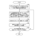
- FIG. 2 is a flowchart diagram showing an example of the flow of three-dimensional measurement processing corresponding to at least one embodiment of the present invention.
- a flow of three-dimensional measurement processing in the three-dimensional measurement apparatus 10 corresponding to at least one embodiment of the present invention will be described with reference to FIG.
- the three-dimensional measurement process is started by generating the dot pattern of this example in the three-dimensional measurement device 10 (step S101).
- a detailed flow of the method for generating the dot pattern of this example will be described with reference to FIGS. 3 and 4.
- FIG. Next, the three-dimensional measurement device 10 controls the projection device 20 so as to project the projection light composed of the dot pattern of this example onto the object (step S102).
- the three-dimensional measurement device 10 controls the imaging device 30 so as to capture images of the object from two directions, and acquires two captured images (step S103).
- the three-dimensional measurement device 10 calculates parallax information for the two captured images (step S104).
- the three-dimensional measuring device 10 identifies the three-dimensional shape of the object based on the parallax information (step S105), and the process ends.
- Dot pattern generation method Next, a method for generating the dot pattern of this example will be described in detail.
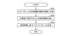
- FIG. 3 is a flowchart diagram showing an example of a rough flow of generating the dot pattern of this example corresponding to at least one embodiment of the present invention.
- the dot pattern of this example is generated by dividing the dot pattern generation range into at least two regions according to the distance from the irradiation center of the projection light in the three-dimensional measurement device 10. (region dividing procedure) (step S201). Any division method may be used as long as the region can be divided according to the distance from the irradiation center.
- the three-dimensional measurement apparatus 10 sets the density of dots in each of the plurality of regions so that the density of dots arranged in each region gradually decreases as the distance from the irradiation center of the projection light increases.
- step S202 density determination procedure
- Any method of specifying the density information may be used, including a method of specifying a specific dot density as a numerical value. A method of specifying such as medium density and low density may be used.
- the three-dimensional measuring apparatus 10 generates the dot pattern of the present example by arranging dots in each of the plurality of regions based on the rule determined by the Poisson disk sampling algorithm and the determined density information. (Dot pattern generation procedure) (Step S203), the generation process is terminated.
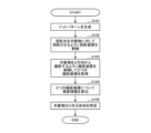
- FIG. 4 is a flowchart diagram showing an example of the flow of the dot pattern generation procedure of this example corresponding to at least one embodiment of the present invention.
- the flow described in FIG. 4 is an example of a more detailed flow of the dot pattern generation procedure in step S203 of FIG.
- the dot pattern generation procedure is started by determining a plurality of reference positions for each region according to rules determined by the Poisson disk sampling algorithm in the three-dimensional measurement device 10 (step S301).
- the three-dimensional measurement apparatus 10 includes a first group to which a plurality of placement patterns with a high dot placement density belong, and a dot placement pattern.
- a second group to which a plurality of layout patterns with a low layout density belong is set, and from which group the layout pattern is to be selected is determined according to the density information set for the area (step S302). At this time, the selection ratio between the first group and the second group is determined in advance for each area.
- the three-dimensional measuring device 10 selects an arrangement pattern from among the determined groups (step S303). The arrangement pattern selected at this time is preferably determined at random.
- the three-dimensional measuring device 10 arranges dots at the reference positions according to the selected arrangement pattern (step S304). In this way, the three-dimensional measuring apparatus 10 repeats the process of executing steps S302 to S304 for one reference position to arrange dots until the dot arrangement is completed for all reference positions (step S305). . Then, the three-dimensional measuring device 10 ends the dot pattern generation procedure when the dot arrangement is completed for all the reference positions (S305-Y).
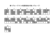
- FIG. 5 is an explanatory diagram explaining an example of arrangement patterns belonging to the first group (group with high dot arrangement density) corresponding to at least one embodiment of the present invention.
- FIG. 5 shows examples of arrangement patterns that are candidates for selection in the dot pattern generation procedure in the dot pattern generation unit 11 .
- there are a total of 14 types of arrangement patterns belonging to the first group each of which is a grid in which 5 dots are arranged in a dot arrangement area capable of arranging a maximum of 9 dots of 3 rows and 3 columns. pattern.
- the 15 types of arrangement patterns in this example are combinations that do not include the same dot arrangement pattern in duplicate and that do not overlap with each other when translated in the dot arrangement area.
- each arrangement pattern is assigned a unique number from 0 to 14.
- FIG. 1 In the selection process by the dot pattern generator 11, any one of 0 to 14 is randomly generated, and an arrangement pattern corresponding to the generated numerical value is selected. Note that when the arrangement pattern indicates that two dots are arranged adjacently, the two dots in the projection light projected by the dot pattern projection control unit 12 may be continuous or may be arranged at a predetermined distance. You can stay away.
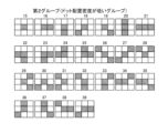
- FIG. 6 is an explanatory diagram explaining an example of arrangement patterns belonging to the second group (group with low dot arrangement density) corresponding to at least one embodiment of the present invention.
- FIG. 6 shows examples of arrangement patterns that are candidates for selection in the dot pattern generation procedure in the dot pattern generation unit 11 .
- there are a total of 25 arrangement patterns belonging to the second group each of which has 1 to 3 dots arranged in a dot arrangement area capable of arranging a maximum of 9 dots of 3 vertical and 3 horizontal dots. It is a grid-like pattern.
- the 25 arrangement patterns in this example are a combination of patterns that do not include the same dot arrangement pattern in duplicate and do not overlap each other when translated in the dot arrangement area.
- each arrangement pattern is assigned a unique number from 15 to 39.
- FIG. In the selection process by the dot pattern generator 11, one of 15 to 39 is randomly generated, and the arrangement pattern corresponding to the generated numerical value is selected.
- FIG. 7 is an explanatory diagram explaining an example of setting density information for each area and an example of a dot arrangement method corresponding to at least one embodiment of the present invention.
- the range for generating a dot pattern is divided into six areas by concentric circles, and for each area, a first group (expressed as [1] in FIG. 7) with a high dot arrangement density and a dot arrangement density 7 shows an example in which the selection ratio is set for the second group (expressed as [2] in FIG. 7) with a low .
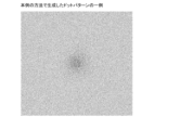
- FIG. 8 is an image diagram showing an example of a dot pattern generated based on the setting of density information for each area and the dot arrangement method corresponding to at least one embodiment of the present invention.
- FIG. 8 shows an example in which a dot pattern is generated by selecting an arrangement pattern from two groups based on the setting of density information for each area shown in FIG.
- FIG. 8 it is possible to generate a dot pattern in which the dot arrangement density is high in the central portion and the dot arrangement density decreases as the distance from the center increases.
- the amount of light in the photographed image data becomes relatively uniform, so that the photographed image does not saturate the dynamic range of the camera. Data can be acquired.
- the dot pattern generation method in order to perform three-dimensional measurement by calculating parallax information by stereo matching, a dot pattern projected onto an object with projection light is generated.
- the dot pattern generation range is divided into at least two regions according to the distance from the irradiation center of the projection light, and the distance from the irradiation center of the projection light is far.
- a dot pattern generation procedure for generating a dot pattern by arranging dots for each of a plurality of areas based on the obtained density information. It is possible to generate a dot pattern in which the density is increased and the dot arrangement density decreases as the distance from the projection light irradiation center increases. By projecting the projection light using the dot pattern generated in this way and performing photographing for three-dimensional measurement, the amount of light in the photographed image data becomes relatively uniform, so that the photographed image does not saturate the dynamic range of the camera. Data can be obtained.
- the dot pattern generation procedure includes determination processing for determining a plurality of reference positions according to rules determined by the Poisson disk sampling algorithm, and arrangement for each of the reference positions.
- a dot pattern is formed by a selection process of selecting one from a plurality of arrangement patterns indicating at least one or more dot arrangements, and an arrangement process of arranging dots based on the arrangement pattern selected for each of the reference positions; is generated, and at least two or more groups are set in advance by classifying the arrangement patterns according to the arrangement density of dots, and the selection process selects from which group the arrangement pattern to be arranged in each area for each area.
- the arrangement pattern to be arranged at each reference position is selected based on a predetermined selection rule that determines whether the By appropriately adjusting the group for selecting the arrangement pattern for each area, such as the area for selecting the arrangement pattern, as a result, the area near the irradiation center of the projection light has a high dot arrangement density, and the area near the irradiation center of the projection light is increased. It is possible to generate a dot pattern in which the dot placement density decreases with increasing distance from .
- the selection rule defines the selection ratio from a plurality of groups for the arrangement pattern to be arranged in each area, so that the density information determined in the area is reflected. Therefore, by setting the ratio of selecting an arrangement pattern from a group with a high dot arrangement density and the ratio of selecting an arrangement pattern from a group with a low dot arrangement density in each area, as a result, the projection light irradiation It is possible to generate a dot pattern in which the dot arrangement density is high in the area near the center and the dot arrangement density decreases as the distance from the projection light irradiation center increases.
- the plurality of arrangement patterns overlap each other when translated in the dot arrangement area regarding which part of the dot arrangement area set in advance to place the dots. Since a combination of non-patterns is used, it is possible to reduce the possibility of erroneous identification in identifying corresponding locations in stereo matching.
- a three-dimensional measuring apparatus is a three-dimensional measuring apparatus for performing three-dimensional measurement on an object, and includes a dot pattern generation unit that generates a dot pattern based on any of the dot pattern generation methods described above.
- a dot pattern projection control unit for controlling a projection device so as to project the projection light composed of the dot pattern onto the object;
- a photographed image acquisition unit that acquires two photographed images by controlling a photographing device, a parallax information calculation unit that calculates parallax information for the two photographed images obtained, and based on the calculated parallax information and a three-dimensional shape specifying unit for specifying the three-dimensional shape of the object. Therefore, it is possible to obtain photographed image data that does not cause blown-out highlights or blocked-up shadows without saturating the dynamic range of the camera. As a result, it is possible to improve the accuracy of identifying corresponding locations in stereo matching.
- the three-dimensional measurement apparatus 10 has a dot pattern generation processing unit that generates the dot pattern of the present example in advance and stores it in a predetermined storage unit instead of generating the dot pattern of the present example in real time in the dot pattern generation unit 11. may be provided.
- the dot pattern projection control unit 12 reads out the dot pattern of the present example from the storage unit and controls the projection device 20 to project the projection light composed of the dot pattern of the present example onto the object.
- the dot pattern may be stored as an image file, or may be stored in the device after the dot pattern is printed on a photomask.
- the dot pattern generation unit 11 performs a determination process of determining a plurality of reference positions according to a rule determined by a Poisson disk sampling algorithm, and arranges for each of the reference positions. Therefore, a selection process for selecting one from a plurality of arrangement patterns indicating at least one or more dot arrangements, and an arrangement process for arranging dots based on the arrangement pattern selected for each of the reference positions.
- a pattern may be generated, and the determination processing may determine the placement density of the reference positions to be placed within the area based on the density information determined for each area.
- the range for generating the dot pattern is divided into a plurality of areas, and the reference position density is increased in the area near the center, and the reference position density decreases as the area moves away from the center.
- the present invention is not limited to this. That is, as long as it is possible to generate a dot pattern such that the dot density near the center of the dot pattern generation range is high and the dot density gradually decreases as the distance from the center increases, the generation method using the arrangement pattern is not limited. .
- dots near the center of the dot pattern generation range A method of generating a dot pattern having a high density and gradually lowering the dot density away from the center may be used.
- REFERENCE SIGNS LIST 10 three-dimensional measurement device 11 dot pattern generation unit 12 dot pattern projection control unit 13 captured image acquisition unit 14 parallax information calculation unit 15 three-dimensional shape identification unit 16 storage unit 20 projection device 30 imaging device
Landscapes
- Engineering & Computer Science (AREA)
- Computer Vision & Pattern Recognition (AREA)
- Physics & Mathematics (AREA)
- General Physics & Mathematics (AREA)
- Length Measuring Devices By Optical Means (AREA)
Priority Applications (2)
| Application Number | Priority Date | Filing Date | Title |
|---|---|---|---|
| JP2024504685A JPWO2023167162A1 (enExample) | 2022-03-01 | 2023-02-28 | |
| EP23763420.9A EP4488619A1 (en) | 2022-03-01 | 2023-02-28 | Dot pattern generation method and three-dimensional measurement device |
Applications Claiming Priority (2)
| Application Number | Priority Date | Filing Date | Title |
|---|---|---|---|
| JP2022031209 | 2022-03-01 | ||
| JP2022-031209 | 2022-03-01 |
Publications (1)
| Publication Number | Publication Date |
|---|---|
| WO2023167162A1 true WO2023167162A1 (ja) | 2023-09-07 |
Family
ID=87883708
Family Applications (1)
| Application Number | Title | Priority Date | Filing Date |
|---|---|---|---|
| PCT/JP2023/007197 Ceased WO2023167162A1 (ja) | 2022-03-01 | 2023-02-28 | ドットパターン生成方法及び3次元計測装置 |
Country Status (3)
| Country | Link |
|---|---|
| EP (1) | EP4488619A1 (enExample) |
| JP (1) | JPWO2023167162A1 (enExample) |
| WO (1) | WO2023167162A1 (enExample) |
Citations (5)
| Publication number | Priority date | Publication date | Assignee | Title |
|---|---|---|---|---|
| JPH0425758B2 (enExample) | 1983-03-31 | 1992-05-01 | Tokyo Shibaura Electric Co | |
| US20190226838A1 (en) * | 2011-08-09 | 2019-07-25 | Apple Inc. | Overlapping pattern projector |
| JP2020071034A (ja) * | 2018-10-29 | 2020-05-07 | セイコーエプソン株式会社 | 三次元計測方法、三次元計測装置、及び、ロボットシステム |
| US20200319341A1 (en) * | 2019-04-03 | 2020-10-08 | Varjo Technologies Oy | Distance-imaging system and method of distance imaging |
| WO2022254854A1 (ja) * | 2021-05-31 | 2022-12-08 | 興和株式会社 | 3次元計測装置 |
-
2023
- 2023-02-28 WO PCT/JP2023/007197 patent/WO2023167162A1/ja not_active Ceased
- 2023-02-28 JP JP2024504685A patent/JPWO2023167162A1/ja active Pending
- 2023-02-28 EP EP23763420.9A patent/EP4488619A1/en active Pending
Patent Citations (5)
| Publication number | Priority date | Publication date | Assignee | Title |
|---|---|---|---|---|
| JPH0425758B2 (enExample) | 1983-03-31 | 1992-05-01 | Tokyo Shibaura Electric Co | |
| US20190226838A1 (en) * | 2011-08-09 | 2019-07-25 | Apple Inc. | Overlapping pattern projector |
| JP2020071034A (ja) * | 2018-10-29 | 2020-05-07 | セイコーエプソン株式会社 | 三次元計測方法、三次元計測装置、及び、ロボットシステム |
| US20200319341A1 (en) * | 2019-04-03 | 2020-10-08 | Varjo Technologies Oy | Distance-imaging system and method of distance imaging |
| WO2022254854A1 (ja) * | 2021-05-31 | 2022-12-08 | 興和株式会社 | 3次元計測装置 |
Also Published As
| Publication number | Publication date |
|---|---|
| JPWO2023167162A1 (enExample) | 2023-09-07 |
| EP4488619A1 (en) | 2025-01-08 |
Similar Documents
| Publication | Publication Date | Title |
|---|---|---|
| CN108683907B (zh) | 光学模组像素缺陷检测方法、装置及设备 | |
| CN109751973B (zh) | 三维测量装置、三维测量方法以及存储介质 | |
| JP5994787B2 (ja) | 形状測定装置、構造物製造システム、形状測定方法、構造物製造方法、形状測定プログラム | |
| US10430962B2 (en) | Three-dimensional shape measuring apparatus, three-dimensional shape measuring method, and storage medium that calculate a three-dimensional shape of an object by capturing images of the object from a plurality of directions | |
| JP2017146298A (ja) | 形状測定システム、形状測定装置及び形状測定方法 | |
| CN111788883A (zh) | 部件贴装状态的检查方法、印刷电路板检查装置及计算机可读记录介质 | |
| TW201520975A (zh) | 產生場景深度圖之方法及裝置 | |
| US20210156677A1 (en) | Three-dimensional measurement apparatus and method | |
| CN108616726A (zh) | 基于结构光的曝光控制方法及曝光控制装置 | |
| JP2019163993A (ja) | 欠陥検査装置および欠陥検査方法 | |
| US12142007B2 (en) | Optical information detection method, device and equipment | |
| EP3394830A1 (en) | Data processing apparatus and method of controlling same | |
| JP2017003331A (ja) | 被計測物の形状を計測する計測装置、算出装置、算出方法及びプログラム | |
| JP7741875B2 (ja) | 3次元計測装置 | |
| WO2023167162A1 (ja) | ドットパターン生成方法及び3次元計測装置 | |
| JP2014035198A (ja) | 形状測定装置、構造物製造システム、形状測定方法、構造物製造方法、及び形状測定プログラム | |
| WO2025139408A1 (zh) | 一种结构光三维重建方法和系统 | |
| JP2014178536A (ja) | 描画データ生成方法、描画方法、描画データ生成装置、および描画装置 | |
| JPWO2013035847A1 (ja) | 形状測定装置、構造物製造システム、形状測定方法、構造物製造方法、形状測定プログラム、コンピュータ読み取り可能な記録媒体 | |
| JP2002131031A (ja) | 三次元形状計測方法および三次元形状計測装置 | |
| US12019958B2 (en) | Method and apparatus for automated test plan generation to measure a measurement object | |
| JP6335809B2 (ja) | 縞パタン画像取得装置、縞パタン画像取得方法、三次元位置特定装置、三次元位置特定方法、およびプログラム | |
| US11023706B2 (en) | Measurement system and measurement method | |
| US20230342900A1 (en) | Certificate determination apparatus, certificate determination method, and recording medium | |
| JP2019066424A (ja) | 3次元形状を導出する装置、方法、及びプログラム |
Legal Events
| Date | Code | Title | Description |
|---|---|---|---|
| 121 | Ep: the epo has been informed by wipo that ep was designated in this application |
Ref document number: 23763420 Country of ref document: EP Kind code of ref document: A1 |
|
| ENP | Entry into the national phase |
Ref document number: 2024504685 Country of ref document: JP Kind code of ref document: A |
|
| WWE | Wipo information: entry into national phase |
Ref document number: 2023763420 Country of ref document: EP |
|
| NENP | Non-entry into the national phase |
Ref country code: DE |
|
| ENP | Entry into the national phase |
Ref document number: 2023763420 Country of ref document: EP Effective date: 20241001 |