WO2023167032A1 - 推定システム、推定方法及びプログラム - Google Patents
推定システム、推定方法及びプログラム Download PDFInfo
- Publication number
- WO2023167032A1 WO2023167032A1 PCT/JP2023/005953 JP2023005953W WO2023167032A1 WO 2023167032 A1 WO2023167032 A1 WO 2023167032A1 JP 2023005953 W JP2023005953 W JP 2023005953W WO 2023167032 A1 WO2023167032 A1 WO 2023167032A1
- Authority
- WO
- WIPO (PCT)
- Prior art keywords
- signal
- transmitter
- radio
- signals
- receiver
- Prior art date
- Legal status (The legal status is an assumption and is not a legal conclusion. Google has not performed a legal analysis and makes no representation as to the accuracy of the status listed.)
- Ceased
Links
Images







Classifications
-
- G—PHYSICS
- G01—MEASURING; TESTING
- G01S—RADIO DIRECTION-FINDING; RADIO NAVIGATION; DETERMINING DISTANCE OR VELOCITY BY USE OF RADIO WAVES; LOCATING OR PRESENCE-DETECTING BY USE OF THE REFLECTION OR RERADIATION OF RADIO WAVES; ANALOGOUS ARRANGEMENTS USING OTHER WAVES
- G01S5/00—Position-fixing by co-ordinating two or more direction or position line determinations; Position-fixing by co-ordinating two or more distance determinations
- G01S5/02—Position-fixing by co-ordinating two or more direction or position line determinations; Position-fixing by co-ordinating two or more distance determinations using radio waves
- G01S5/04—Position of source determined by a plurality of spaced direction-finders
-
- G—PHYSICS
- G01—MEASURING; TESTING
- G01S—RADIO DIRECTION-FINDING; RADIO NAVIGATION; DETERMINING DISTANCE OR VELOCITY BY USE OF RADIO WAVES; LOCATING OR PRESENCE-DETECTING BY USE OF THE REFLECTION OR RERADIATION OF RADIO WAVES; ANALOGOUS ARRANGEMENTS USING OTHER WAVES
- G01S5/00—Position-fixing by co-ordinating two or more direction or position line determinations; Position-fixing by co-ordinating two or more distance determinations
- G01S5/02—Position-fixing by co-ordinating two or more direction or position line determinations; Position-fixing by co-ordinating two or more distance determinations using radio waves
- G01S5/14—Determining absolute distances from a plurality of spaced points of known location
Definitions
- the present disclosure relates to an estimation system, estimation method and program, and more particularly to an estimation system, estimation method and program for estimating the position of a transmitter.
- Patent Document 1 describes a positioning system that measures the position of a wireless terminal (transmitter).
- a wireless terminal transmits a plurality of positioning signals (radio signals), and a base station receives the plurality of positioning signals by changing directivity. Then, the positioning system described in Patent Literature 1 performs position calculation based on all combinations of reception of a plurality of positioning signals, and selects a combination that results in the smallest position calculation error.
- An object of the present disclosure is to provide an estimation system, an estimation method, and a program that can reduce the amount of computation when estimating the position of a transmitter.
- An estimation system includes a transmitter and an estimation unit.
- the transmitter outputs a plurality of radio signals different from each other.
- the estimator estimates the position of the transmitter based on a plurality of received signals.
- the plurality of received signals are generated by a receiver that receives the plurality of wireless signals.
- the estimator estimates the position of the transmitter using the maximum value of received power of the plurality of received signals or the average value of the received power of the plurality of received signals.
- An estimation method includes a transmission step and an estimation step.
- the transmitter transmits a plurality of different radio signals.
- the estimating step estimates the position of the transmitter using a plurality of received signals.
- the plurality of received signals are generated by a receiver that receives the plurality of wireless signals.
- the position of the transmitter is estimated using the maximum value of received power of the plurality of received signals or the average value of the received power of the plurality of received signals.
- a program according to one aspect of the present disclosure causes one or more processors to execute the estimation method.
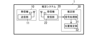
- FIG. 1 is a functional block diagram showing the configuration of an estimation system according to Embodiment 1.
- FIG. FIG. 2 is a sequence diagram showing the operation of the estimation system;
- FIG. 3 is a graph showing the relationship between the distance between the transmitter and receiver and the signal strength of the received signal.
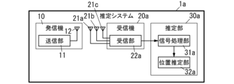
- FIG. 4 is a functional block diagram showing the configuration of the estimation system according to the second embodiment.
- FIG. 5 is a functional block diagram showing the configuration of a receiver in the estimation system;
- FIG. 6 is a sequence diagram showing the operation of the estimation system;
- FIG. 7 is a functional block diagram showing the configuration of an estimation system according to the third embodiment.
- FIG. 8 is a functional block diagram showing the configuration of a transmitter in the estimation system according to Embodiment 4.
- FIG. 9 is a functional block diagram showing the configuration of a transmitter in the estimation system according to Embodiment 5.
- FIG. 10 is a functional block diagram showing the configuration of a transmitter in the estimation system according to Embodiment 6.
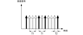
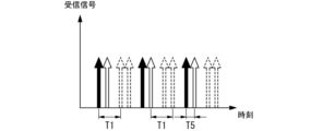
- FIG. 11 is a schematic diagram showing the timing of radio signals in the estimation system of the same.
- FIG. 12 is a schematic diagram showing the timing of radio signals in Comparative Example 1.
- FIG. 13 is a schematic diagram showing the timing of radio signals in Comparative Example 2.
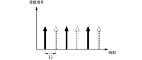
- FIG. FIG. 14 is a schematic diagram showing the timing of radio signals in Comparative Example 3.
- FIG. 15 is a functional block diagram showing the configuration of an estimation system according to Embodiment 7.
- FIG. FIG. 16 is a sequence diagram showing the operation of the estimation system;
- the estimation system 1 is a positioning system (LPS: Local Positioning System) that measures the position of a transmitter 10 that transmits a radio signal using radio waves as a medium.
- LPS Local Positioning System
- an estimation system 1 includes a transmitter 10, a plurality of receivers 20 (only one is shown in FIG. 1), and an estimator 30. .
- the transmitter 10 is a beacon device that transmits a plurality of radio signals Tx1 and Tx2 (see FIG. 2).
- the transmitter 10 has a transmitter 11 and an antenna 12 .
- the transmission unit 11 is a circuit that generates a plurality of different radio signals and transmits them from the antenna 12.
- the radio signals Tx1 and Tx2 are, for example, beacon signals conforming to the BLE (Bluetooth (registered trademark) Low Energy) standard.
- the radio signal includes information such as identification information of the transmitter 10, for example.
- the identification information of the transmitter 10 is, for example, a MAC (Media Access Control) address.
- Receiver 20 is a receiving device for receiving the radio signals Tx1 and Tx2 transmitted by the transmitter 10 .
- the estimation system 1 includes a plurality of receivers 20, only one receiver 20 is shown in FIG.
- Receiver 20 includes antenna 21 and receiver 22 .
- the receiving unit 22 uses the antenna 21 to receive the radio signals Tx1 and Tx2 transmitted by the transmitter 10 .
- the receiver 22 outputs the signal strength of the received signal corresponding to each of the radio signals Tx1 and Tx2.
- the signal strength of the received signal is, for example, RSSI (Received Signal Strength Indicator).
- RSSI Received Signal Strength Indicator
- the receiving unit 22 outputs the signal strength Rx1 (see FIG. 2) of the received signal corresponding to the radio signal Tx1 and the signal strength Rx2 (see FIG. 2) of the received signal corresponding to the radio signal Tx2. do.
- the estimating unit 30 estimates the position of the transmitter 10 based on the signal strengths Rx1 and Rx2 output by the plurality of receivers 20 and the positional information of each receiver 20 .
- the estimating section 30 includes a signal processing section 31 and a position estimating section 32 .
- the signal processing unit 31 receives multiple signal strengths Rx1 and Rx2 from each of the multiple receivers 20 . More specifically, the signal processing unit 31 receives the signal strength Rx1 of the received signal corresponding to the radio signal Tx1 and the signal strength Rx2 of the received signal corresponding to the radio signal Tx2 from each of the plurality of receivers 20. . Then, the signal processing unit 31 calculates the representative value Rx of the received signal corresponding to the radio signal transmitted by the transmitter 10 for each receiver 20 .
- the signal processing unit 31 calculates the maximum value among the plurality of signal strengths Rx1 and Rx2 as the representative value Rx of the received signal. For example, the signal processing unit 31 calculates the maximum value of the signal strength Rx1 of the received signal corresponding to the radio signal Tx1 and the signal strength Rx2 of the received signal corresponding to the radio signal Tx2 as the representative value Rx of the received signal.
- the signal processing unit 31 outputs the representative value Rx of the received signal calculated for each receiver 20 to the position estimation unit 32 .
- Position Estimating Unit uses the representative value Rx of the received signals of the plurality of receivers 20 and the position information of each of the plurality of receivers 20 to determine the position of the transmitter 10. to estimate
- the position estimation unit 32 estimates the distance between the receiver 20 and the transmitter 10 for each receiver 20 based on the representative value Rx of the received signal. For example, the position estimation unit 32 calculates the attenuation of the radio signal Tx1 or Tx2 based on the representative value Rx of the received signal and the power of the radio signals Tx1 and Tx2 of the transmitter 10, and compares the attenuation with the receiver 20. Convert to the distance to the transmitter 10 .
- the position estimation unit 32 estimates the distance between the receiver 20 and the transmitter 10 for each receiver 20 and estimates the position of the transmitter 10 using the position information of each receiver 20 .
- the position estimation unit 32 includes, for example, a storage unit (not shown) that holds the positions (coordinates) of each receiver 20 .
- the position estimation unit 32 draws a sphere centered at the receiver 20 and having a radius defined as the distance between the receiver 20 and the transmitter 10 in the virtual space. The coordinates of the intersection point are calculated as the position of the transmitter 10 .
- the transmitter 10 outputs a radio signal Tx1 (step S1).
- a part of the radio signal Tx1 output from the antenna 12 of the transmitter 10 (hereinafter referred to as "direct wave”) reaches the antenna 21 of each receiver 20 directly.
- part of the radio signal Tx1 output from the antenna 12 of the transmitter 10 (hereinafter referred to as "reflected wave”) reaches the antenna 21 after being reflected by an object different from the transmitter 10 and the receiver 20. .
- each of the receivers 20 performs reception processing for the radio signal Tx1 (step S2).
- Each receiver 20 outputs the signal strength Rx1 of the received signal based on the radio signal Tx1.
- the transmitter 10 outputs a radio signal Tx2 (step S3).
- the radio signal Tx2 output from the antenna 12 of the transmitter 10 reaches the antenna 21 of each receiver 20 directly, or reaches the antenna 21 after being reflected by an object different from the transmitter 10 and the receiver 20. do.
- each of the receivers 20 performs reception processing for the radio signal Tx2 (step S4).
- Each of the receivers 20 outputs the signal strength Rx2 of the received signal based on the radio signal Tx2.
- the signal processing section 31 of the estimating section 30 calculates a representative value Rx of received signals corresponding to the radio signals Tx1 and Tx2 transmitted by the transmitter 10 for each receiver 20 (step S5).
- the signal processing unit 31 calculates the maximum value of the signal strength Rx1 and the signal strength Rx2 for each receiver 20 as the representative value Rx of the received signal.
- the position estimating section 32 of the estimating section 30 estimates the position of the transmitter 10 (step S6).
- the position estimator 32 estimates the distance between the receiver 20 and the transmitter 10 for each receiver 20 based on the representative value Rx of the received signal.
- the position estimating unit 32 calculates the amount of attenuation of the radio signal based on, for example, the representative value Rx of the received signal and the power of the radio signal of the transmitter 10, and the distance between the receiver 20 and the transmitter 10 is Convert.
- the position estimation unit 32 estimates the distance between each receiver 20 and the transmitter 10 and estimates the position of the transmitter 10 using the position information of each receiver 20 .
- the signal processing unit 31 calculates the reception signal representative value Rx corresponding to the radio signal transmitted by the transmitter 10 for each receiver 20 . For example, the signal processing unit 31 calculates the maximum value of the signal strength Rx1 of the received signal corresponding to the radio signal Tx1 and the signal strength Rx2 of the received signal corresponding to the radio signal Tx2 as the representative value Rx of the received signal.
- FIG. 3 shows the value of the signal strength of the received signal with respect to the distance between the transmitter 10 and the receiver 20.
- the dashed line indicates the theoretical value of the signal strength when only the direct wave directly reaching the receiver 20 from the transmitter 10 reaches the receiver 20 .
- the solid line indicates the theoretical value when both the direct wave and the reflected wave that reaches the receiver 20 after being reflected after being output from the transmitter 10 arrive.
- the dashed-dotted line in FIG. 3 is the measured value of the signal strength of the signal received by the receiver 20 when the power of the radio signal is kept constant and the distance between the transmitter 10 and the receiver 20 is changed. .
- the reflected wave path between the transmitter 10 and the receiver 20 is not limited to one, even if the positional relationship between the transmitter 10 and the receiver 20 is the same, the influence of the reflected wave is not constant.
- the radio signal Tx1 and the radio signal Tx2 have the same power, and the positional relationship between the transmitter 10 and the receiver 20 is the same, but the signal strength is different. .
- the position of the transmitter 10 is estimated using the signal strength Rxa of the received signal, the estimated distance between the receiver 20 and the transmitter 10 is the distance between the receiver 20 and the transmitter 10 get bigger. Therefore, the distance between transmitter 10 and receiver 20 is not correctly predicted, and the error in the predicted position of transmitter 10 increases.
- the signal processing unit 31 for each receiver 20, out of the signal strength Rx1 of the received signal corresponding to the radio signal Tx1 and the signal strength Rx2 of the received signal corresponding to the radio signal Tx2 The maximum value is calculated as the representative value Rx of the received signal.
- the signal strength Rx1 of the received signal and the signal strength Rx2 of the received signal the stronger signal strength is likely to be less affected by the reflected wave.
- the influence of the reflected wave can be suppressed by a simple method. can be done.
- the transmitter 10 transmits different radio signals Tx1 and Tx2, and the receivers 20 output signal strengths Rx1 and Rx2 of received signals corresponding to the radio signals Tx1 and Tx2.
- the number of radio signal transmissions is not limited to two, and may be three or more.
- the receiver 20 outputs the signal strength of the received signal in one-to-one correspondence with the radio signal.
- the signal processing unit 31 of the estimating unit 30 calculates, for each receiver 20, the maximum value among the signal strengths of a plurality of received signals corresponding to the radio signal on a one-to-one basis as the representative value Rx of the received signals.
- the transmitter 10 transmits a plurality of different radio signals Tx1 and Tx2. Also, the signal processing unit 31 of the estimating unit 30 calculates a representative value Rx of the received signal corresponding to the radio signal transmitted by the transmitter 10 for each receiver 20 . Also, the position estimator 32 of the estimator 30 estimates the position of the transmitter 10 using the representative value Rx of the received signal corresponding to the receiver 20 on a one-to-one basis.
- the estimating unit 30 uses the received signal, which is considered to have the smallest influence of the reflected wave, as the representative signal, and uses the signal strength of the representative signal to Estimate the position of As a result, the estimation system 1 according to the first embodiment can reduce the influence of reflected waves and improve the accuracy of position estimation of the transmitter 10 .
- the representative value Rx of the received signal is calculated for each receiver 20 and the position of the transmitter 10 is estimated using the representative value Rx of the received signal for each receiver 20 . Therefore, even if the number of radio signal transmissions increases, an increase in the amount of calculation can be suppressed.
- the signal processing unit 31 calculates, for each receiver 20, the maximum value among the signal strengths of a plurality of received signals as the representative value Rx of the received signals.
- the representative value Rx of the received signal is not limited to the maximum value among the signal strengths Rx1 and Rx2 of the received signal.
- the average value of the signal strengths Rx1 and Rx2 of the received signals is calculated as the representative value Rx of the received signals.
- the signal processing unit 31 acquires the signal strength of the received signal corresponding to each radio signal on a one-to-one basis from each of the receivers 20 .
- the signal processing unit 31 receives signal strengths Rxi (i is an integer of 1 or more and n or less) of n received signals for n radio signals (n is an integer of 2 or more) from each of the receivers 20. do.
- the signal strength Rxi is the signal strength of the received signal corresponding to the i-th radio signal Txi.
- the signal processing unit 31 calculates the average value of the signal strengths Rxi of the received signals for each receiver 20 as the representative value Rx of the received signals. That is, the representative value Rx of the received signal is expressed by the following formula.
- the signal strength Rxi of the received signal corresponding to the radio signal Txi and the signal strength Rxj of the received signal corresponding to the radio signal Txj (j is an integer from 1 to n and i ⁇ j) Propagation routes are not significantly different. Therefore, the difference in components caused by direct waves is small between the signal strength Rxi of the received signal and the signal strength Rxj of the received signal.
- the signal strength Rxi of the received signal corresponding to the radio signal Txi and the signal strength Rxj of the received signal corresponding to the radio signal Txj may have different propagation paths of reflected waves.
- the difference in the component due to the reflected wave is larger than the difference in the component due to the direct wave. Therefore, by calculating the average value of the signal strengths Rxi of a plurality of received signals and calculating the representative value Rx of the received signals, the effect of the direct wave on each of the signal strengths Rxi of the received signals is strengthened and the reflected wave can cancel each other out. That is, the representative value Rx of the received signal is less affected by the reflected wave than each of the signal strengths Rxi of the received signal.
- the estimation system 1 according to the modified example of the first embodiment can also suppress the influence of reflected waves by a simple method.
- the estimation system 1 calculates the representative value Rx of the received signal for each receiver 20, estimates the distance between each receiver 20 and the transmitter 10, and estimates the position of the transmitter 10. .
- the method of estimating the position of transmitter 10 is not limited to the above method.
- the estimation system 1a according to the second embodiment includes a plurality of receivers 20a and an estimating unit 30a (only one is shown in FIG. 4) instead of the plurality of receivers 20 and the estimating unit 30.
- the estimation system 1a according to the second embodiment is similar to the first embodiment in that the receiver 20a and the estimation unit 30a estimate the direction of the propagation path between the transmitter 10 and the receiver 20a and estimate the position of the transmitter 10. It is different from estimation system 1.
- an estimation system 1a includes a transmitter 10, a plurality of receivers 20a, and an estimation section 30a.
- the receiver 20a is a receiving device for receiving the radio signals Tx1 and Tx2 output by the transmitter .
- the estimation system 1a includes a plurality of receivers 20a, but FIG. 4 shows one receiver 20a.
- the receiver 20a includes three antennas 21a to 21c and a receiver 22a.
- the receiving unit 22a receives the radio signals Tx1 and Tx2 output by the transmitter 10 using the three antennas 21a to 21c.
- the receiving unit 22a performs synthesis processing on three input signals IS1 to IS3 (see FIG. 5) input from each of the three antennas 21a to 21c, and generates four synthesized signals SS1 to SS4 (see FIG. 5). Output.
- the receiving section 22a includes a phase synthesizing section 25 and an output section .
- the phase synthesizer 25 includes a plurality of (five in the illustrated example) phase synthesizers 23a, 23b, 23c, 23d, and 23e.
- the phase synthesizers 23a, 23b, 23c, 23d, and 23e are referred to as the phase synthesizers 23 when they are not distinguished from each other.
- the phase synthesizer 23 is composed of, for example, a 90-degree hybrid unit (hybrid element).
- the phase synthesizer 23 generates a signal whose power value is 1/ ⁇ 2 times as large as the three input signals IS1 to IS3 input to the first input terminal I1 and the second input terminal I2. Output from the output terminal O1 and the second output terminal O2. Further, the phase synthesizer 23 outputs a signal having the same phase from the first output terminal O1 as compared with the three input signals IS1 to IS3 input to the first input terminal I1, and outputs a signal whose phase is delayed by 90 degrees. Output from the second output terminal O2.
- the phase synthesizer 23a outputs from the first output terminal O1 a signal IS4 having a power value 1/ ⁇ 2 times as large as the input signal IS1 input to the first input terminal I1 and having the same phase.
- the phase synthesizer 23b outputs from the second output terminal O2 a signal IS5 whose power value is 1/ ⁇ 2 times the input signal IS2 input to the first input terminal I1 and whose phase is delayed by 90 degrees. Further, the phase synthesizer 23b outputs a signal IS6 having a power value 1/ ⁇ 2 times as large as that of the input signal IS2 and having the same phase as the input signal IS2 from the first output terminal O1.
- the phase synthesizer 23c outputs from the second output terminal O2 a signal IS7 having a power value 1/ ⁇ 2 times as large as the input signal IS3 input to the second input terminal I2 and having the same phase.
- the phase synthesizer 23d receives the signal IS4 at the second input terminal I2 and the signal IS5 at the first input terminal I1.
- the phase synthesizer 23d generates a signal whose power value is 1/ ⁇ 2 times that of the signal IS4 and whose phase is delayed by 90 degrees, and a signal whose power value is 1/ ⁇ 2 times that of the signal IS5 and whose phase is the same.
- the combined signal SS1 is output from the first output terminal O1.
- the phase synthesizer 23d generates a signal whose power value is 1/ ⁇ 2 times as large as the signal IS4 and has the same phase as that of the signal IS4, and a signal whose power value is 1/ ⁇ 2 times as large as that of the signal IS5 and whose phase is delayed by 90 degrees. , is output from the second output terminal O2.
- the phase synthesizer 23e receives the signal IS6 at the second input terminal I2 and the signal IS7 at the first input terminal I1.
- the phase synthesizer 23e generates a signal whose power value is 1/ ⁇ 2 times that of the signal IS6 and whose phase is delayed by 90 degrees, and a signal whose power value is 1/ ⁇ 2 times that of the signal IS7 and whose phase is the same.
- the combined signal SS3 is output from the first output terminal O1.
- the phase synthesizer 23e generates a signal having a power value 1/ ⁇ 2 times as large as the signal IS6 and having the same phase as that of the signal IS6, and a signal having a power value 1/ ⁇ 2 times as large as the signal IS7 and having a phase lag of 90 degrees. , is output from the second output terminal O2.
- the output unit 24 outputs four synthesized signals SS1 to SS4 generated by the phase synthesizing unit 25 for each radio signal to the estimating unit 30 .
- a combination (signal set) of synthesized signals SS1, SS2, SS3, and SS4 corresponding to the i-th radio signal is hereinafter referred to as a received signal set Rvi.
- Synthesized signals SS1, SS2, SS3, and SS4 included in the received signal set Rvi are referred to as synthesized signals SSi1, SSi2, SSi3, and SSi4, respectively.
- the synthesized signals SS1, SS2, SS3, and SS4 included in the received signal set Rv1 corresponding to the first radio signal Tx1 are respectively synthesized signals SS11, SS12, SS13, and SS14 (see FIG. 6).
- the combined signals SS1, SS2, SS3, and SS4 included in the received signal set Rv2 corresponding to the second radio signal Tx2 are combined signals SS21, SS22, SS23, and SS24 (see FIG. 6).
- the estimation unit 30a receives a received signal set Rvi corresponding to each of a plurality of radio signals from a plurality of receivers 20a.
- the estimation unit 30a calculates a representative signal Rr of the received signal set Rvi for each receiver 20a.
- the estimation unit 30a then estimates the position of the transmitter 10 based on the representative signal Rr for each receiver 20a.
- the estimation unit 30a includes a signal processing unit 31a and a position estimation unit 32a.
- the signal processing section 31a receives a reception signal set Rvi corresponding to each of the plurality of radio signals from each of the plurality of receivers 20a. Then, the signal processing unit 31a calculates the representative signal Rr for each receiver 20a.
- the signal processing unit 31a performs the following processing for each receiver 20a. That is, the signal processing unit 31a generates a representative signal of all SS1 included in a plurality of received signal sets Rvi, and sets it as a representative signal SSr1 of the combined signal SS1.
- the representative signal SSr1 is, for example, the amplitude value of the synthesized signal SS1 having the highest signal strength among the plurality of SS1. For example, when the transmitter 10 transmits two radio signals Tx1 and Tx2, the signal The amplitude value of the synthesized signal with a large intensity is assumed to be a representative signal SSr1.
- the signal processing unit 31a generates a representative signal of all SSi2 included in the plurality of received signal sets Rvi, and sets it as a representative signal SSr2 of the combined signal SS2.
- the representative signal SSr2 is, for example, the amplitude value of the synthesized signal with the highest signal strength among the plurality of SSi2.
- the signal processing unit 31a generates a representative signal of all SSi3 included in a plurality of received signal sets Rvi, and sets it as a representative signal SSr3 of the synthesized signal SS3.
- the representative signal SSr3 is, for example, the amplitude value of the synthesized signal with the highest signal strength among the plurality of SSi3.
- the signal processing unit 31a generates representative signals of all SSi4 included in the plurality of received signal sets Rvi, and sets them as representative signals SSr4 of the combined signal SS4.
- the representative signal SSr4 is, for example, the amplitude value of the synthesized signal with the highest signal strength among the plurality of SSi4.
- the signal processing unit 31a outputs a combination of representative signals SSr1, SSr2, SSr3, and SSr4 calculated for each receiver 20a as a representative signal Rr corresponding to the receiver 20a.
- Position Estimating Unit The position estimating unit 32a estimates the position of the transmitter 10 using the representative signal Rr for each of the plurality of receivers 20a and the position information of each of the plurality of receivers 20. do.
- the complex propagation channel between the antenna 21a of the receiver 20a and the antenna 12 of the transmitter 10 be h1.
- a complex propagation channel between the antenna 21b of the receiver 20a and the antenna 12 of the transmitter 10 is h2.
- a complex propagation channel between the antenna 21c of the receiver 20a and the antenna 12 of the transmitter 10 is h3.
- Let d1 be the distance between the antennas 21a and 21b and the distance between the antennas 21b and 21c.
- the transmitter 10 is located at an angle ⁇ 1 with respect to the broadside direction of the array antenna composed of the antennas 21a, 21b, and 21c.
- the propagation channels can be collectively expressed as Equation (1).
- Equation (2) The correlation matrix R of this propagation channel can be expressed as Equation (2).
- the symbol H indicates complex conjugate transposition
- the symbol * indicates complex conjugate.
- the diagonal terms of the correlation matrix R are real numbers, and the off-diagonal terms are complex numbers.
- indicates the value of the representative signal SSr1 of the synthesized signal SS1 output from the first output terminal O1 of the phase synthesizer 23d.
- indicates the value of the representative signal SSr2 of the synthesized signal SS2 output from the second output terminal O2 of the phase synthesizer 23d.
- indicates the value of the representative signal SSr3 of the synthesized signal SS3 output from the first output terminal O1 of the phase synthesizer 23e.
- indicates the value of the representative signal SSr4 of the synthesized signal SS4 output from the second output terminal O2 of the phase synthesizer 23e.
- the channel gains on the left side of Equations (3) to (6) can be expressed by Equations (7) to (10).
- Equation (11) Focusing on the gain difference obtained via the phase synthesizer 23d, Equation (11) is obtained.
- Equation (13) focusing on the sum of the gains obtained via the phase synthesizer 23d, Equation (13) is obtained from the relation of the arithmetic mean.
- Equation (14) which is the deflection angle of R12
- Equation (15) is obtained.
- Equation (2) the correlation matrix for representative signals SSr1 and SSr2 is defined as R1. Representing the correlation matrix R1 in terms of A and ⁇ yields equation (16).
- Equation (17) focusing on the gain difference obtained via the phase synthesizer 23e, Equation (17) is obtained, and the imaginary parts of R23 and R32 can be obtained.
- ⁇ indicates the deflection angle of R23.
- Equation (18) is obtained from the relation of the arithmetic mean.
- the propagation loss from the antenna 12 to the antenna 21b of the transmitter 10 is equal to the propagation loss from the antenna 12 to the antenna 21c, and
- Equation (20) is obtained.
- B is a real constant.
- the correlation matrix relating to representative signals SSr3 and SSr4 is defined as R2. Representing the correlation matrix R2 in terms of B and ⁇ yields equation (21) to estimate the correlation matrix.
- R13 represents the correlation of radio signals between the antennas 21a and 21c.
- R13 can be expressed by Equation (22) using the determined
- the position estimation unit 32 can estimate the direction of the transmitter 10 by using various direction-of-arrival estimation algorithms for the correlation matrix R. Specifically, when the beamformer method is used, the position estimator 32 calculates the correlation between the correlation matrix R and the steering vector from the product of the correlation matrix R and the steering vector (theoretical value) represented by Equation (24). By taking this, the direction of the transmitter 10 can be estimated.
- the position estimation unit 32 substitutes various values for ⁇ in equation (25), and determines that the direction in which the evaluation function P( ⁇ ) is maximized is the direction of the transmitter 10 relative to the receiver 20a. .
- the position estimation unit 32 performs the above estimation for each receiver 20a, and estimates the existence range of the transmitter 10 based on the position of the receiver 20a.
- the existence range of the transmitter 10 is estimated on a straight line passing through the positions of the antennas 21a to 21c of the receiver 20a. Then, the position estimating unit 32 draws the existence range of the transmitter 10 based on the position of the receiver 20a in the virtual space, and calculates the position of the intersection of the existence range of the transmitter 10 as the position of the transmitter 10. do.
- the transmitter 10 outputs a radio signal Tx1 (step S1).
- a part of the radio signal Tx1 output from the antenna 12 of the transmitter 10 directly reaches each of the antennas 21a to 21c of each receiver 20a.
- a part of the radio signal Tx1 output from the antenna 12 of the transmitter 10 reaches each of the antennas 21a to 21c after being reflected by an object different from the transmitter 10 and the receiver 20a.
- each of the receivers 20a performs reception processing for the radio signal Tx1 (step S12).
- Each of the receivers 20a outputs synthesized signals SS11 to SS14 based on the radio signal Tx1.
- the transmitter 10 outputs a radio signal Tx2 (step S3).
- the radio signal Tx2 output from the antenna 12 of the transmitter 10 reaches the antennas 21a to 21c of each receiver 20a directly, or after being reflected by an object different from the transmitter 10 and the receiver 20a, reaches the antenna 21a. ⁇ 21c.
- each of the receivers 20a performs reception processing for the radio signal Tx2 (step S14).
- Each of the receivers 20a outputs combined signals SS21 to SS24 based on the radio signal Tx2.
- the signal processing section 31a of the estimating section 30a outputs a representative signal Rr corresponding to the radio signals Tx1 and Tx2 transmitted by the transmitter 10 for each receiver 20a (step S15).
- the signal processing unit 31a performs the following processing for each receiver 20a.
- the signal processing unit 31a sets the amplitude value of the synthesized signal having the greater signal strength among the synthesized signal SS11 and the synthesized signal SS21 as the representative signal SSr1.
- the signal processing unit 31a sets the amplitude value of the synthesized signal having the greater signal strength among the synthesized signal SS12 and the synthesized signal SS22 as the representative signal SSr2.
- the signal processing unit 31a sets the amplitude value of the synthesized signal having the greater signal strength among the synthesized signal SS13 and the synthesized signal SS23 as the representative signal SSr3. Further, the signal processing unit 31a sets the amplitude value of the synthesized signal having the greater signal strength among the synthesized signal SS14 and the synthesized signal SS24 as the representative signal SSr4.
- the position estimation unit 32a of the estimation unit 30a estimates the position of the transmitter 10 (step S16).
- the position estimator 32a estimates the azimuth of the transmitter 10 relative to the receiver 20a based on the representative signal Rr for each receiver 20a.
- the position estimation unit 32 estimates the azimuth of the transmitter 10 for each receiver 20 and estimates the position of the transmitter 10 using the position information of each receiver 20a.
- the transmitter 10 transmits a plurality of different radio signals Tx1 and Tx2. Also, the signal processing unit 31a of the estimation unit 30a calculates a representative signal Rr corresponding to the radio signal transmitted by the transmitter 10 for each receiver 20a. Further, the position estimator 32a of the estimator 30a estimates the position of the transmitter 10 using the representative signal Rr corresponding to the receiver 20a on a one-to-one basis.
- the estimating unit 30a estimates the position of the transmitter 10 using the amplitude values SSr1, SSr2, SSr3, and SSr4 of the combined signals with small influence of the reflected wave and large signal strength for each of the combined signals SS1 to SS4 for each receiver 20a. used for As a result, in the estimation system 1a according to the second embodiment, the influence of reflected waves can be reduced, and the accuracy of position estimation of the transmitter 10 can be improved.
- the representative signal Rr is calculated for each receiver 20a, and the position of the transmitter 10 is estimated using the representative signal Rr for each receiver 20a. Therefore, even if the number of radio signal transmissions increases, an increase in the amount of calculation can be suppressed.
- the signal with the maximum signal strength in the composite signal SS1, the signal with the maximum signal strength in the composite signal SS2, the signal with the maximum signal strength in the composite signal SS3, and the composite signal A signal having the maximum signal strength among SS4 is defined as a representative signal Rr.
- each component of the representative signal Rr is not limited to the signal with the maximum signal strength.
- the average signal strength of the combined signal SS1 for example, for each receiver 20a, the average signal strength of the combined signal SS1, the average signal strength of the combined signal SS2, the average signal strength of the combined signal SS3, and the combined
- the average of the signal strength of the signal SS4 be a representative signal Rr.
- the signal processing unit 31a acquires synthesized signals SS1 to SS4 from each of the receivers 20a.
- the signal processing unit 31a averages the signal strength of the combined signal SSi1 corresponding to each of the n radio signals to obtain the signal strength of the representative signal SSr1. That is, the signal processing unit 31a calculates the signal strength of the representative signal SSr1 based on the following formula.
- the signal processing unit 31a calculates a representative signal SSr2 based on the following formula.
- the signal processing unit 31a calculates a representative signal SSr3 based on the following formula.
- the signal processing unit 31a calculates a representative signal SSr4 based on the following formula.
- the estimation system 1a according to the modified example can also suppress the influence of reflected waves by a simple method.
- a transmitter 10b includes a transmitter 11b and antennas 12a and 12b having different planes of polarization.
- the transmitter 11b of the transmitter 10b outputs the radio signal Tx1 from the antenna 12a and the radio signal Tx2 from the antenna 12b.
- a transmitter 10b includes a transmitter 11b and multiple antennas 12a and 12b.
- the antenna 12a and the antenna 12b have different planes of polarization of the output radio signals.
- the antennas 12a and 12b for example, output radio signals whose planes of polarization are orthogonal to each other.
- Antenna 12a and antenna 12b are implemented, for example, as a single dual-polarized patch antenna.
- the antenna 21 of the receiver 20 receives radio signal components along one plane of polarization.
- the receiver 20 may have a plurality of antennas, but all the antennas commonly receive radio signal components along one plane of polarization.
- the transmitter 11b of the transmitter 10b according to the third embodiment uses the antenna 12a to transmit the radio signal Tx1. Also, the transmitter 11b of the transmitter 10b according to the third embodiment uses the antenna 12b to transmit the radio signal Tx2.
- the radio signal Tx1 and the radio signal Tx2 have different planes of polarization.
- the plane of polarization of the direct wave does not change along the propagation path, but the plane of polarization of the reflected wave may differ from that before reflection to that after reflection. Therefore, the plane of polarization of the direct wave is the same as the plane of polarization of the radio signal output from the transmitter 10b, but the reflected wave has a polarization component in a plane orthogonal to the plane of polarization of the radio signal output from the transmitter 10b.
- the received signal corresponding to the radio signal Tx1 and the received signal corresponding to the radio signal Tx2 are the direct wave and the reflected wave. Different signal strength ratios with waves.
- the antenna 21 of the receiver 20 receives vertically polarized waves.
- the radio signal Tx1 is a vertically polarized wave
- the direct wave is a vertically polarized wave and the reflected wave may contain a horizontally polarized wave component. Therefore, the received signal corresponding to the radio signal Tx1 has a strong direct wave component.
- the radio signal Tx2 is a horizontally polarized wave, so the direct wave is a horizontally polarized wave and the reflected wave may include a vertically polarized wave component.
- the reflected wave component is strong in the received signal corresponding to the radio signal Tx2.
- the signal strength of the received signal corresponding to the radio signal Tx1 is greater than the signal strength of the received signal corresponding to the radio signal Tx2. That is, the signal strength of the received signal is greater as the influence of the direct wave is stronger and the influence of the reflected wave is smaller.
- the signal strength Rx1 of the received signal corresponding to the radio signal Tx1 and the signal strength Rx2 of the received signal corresponding to the radio signal Tx2 are set for each receiver 20. and the maximum value is taken as the representative value Rx of the received signal.
- the receiver 20 and the estimation unit 30 as in the modification of the first embodiment, for each receiver 20, the signal strength Rx1 of the received signal corresponding to the radio signal Tx1 and the strength of the received signal corresponding to the radio signal Tx2 The average value of the signal strength Rx2 may be used as the representative value Rx of the received signal. Further, similarly to the second embodiment or the modified example of the second embodiment, the receiver 20 outputs synthesized signals SS11 to SS14 corresponding to the radio signal Tx1 and synthesized signals SS21 to SS24 corresponding to the radio signal Tx2. , the position of the transmitter 10b may be estimated based on these.
- the transmitter 10b according to the third embodiment includes antennas 12a and 12b having different planes of polarization. Therefore, when the transmitter 10b is a portable device, the polarization plane of either the antenna 12a or the antenna 12b is the same as that of the antenna of the receiver 20 regardless of the orientation of the transmitter 10b. is likely to be close to That is, among the received signal corresponding to the radio signal Tx1 and the received signal corresponding to the radio signal Tx2, the influence of the reflected wave on the received signal with high signal strength is greater than the influence of the reflected wave on the received signal with low strength. small. Therefore, regardless of the direction of the transmitter 10b, the influence of the reflected wave can be suppressed by a simple method.
- the transmitter 10 outputs a plurality of radio signals Tx1 and Tx2 from a single antenna 12 with the same directivity.
- the transmitter 10c according to the fourth embodiment changes the directivity of the antenna 12 with the radio signal Tx1 and the radio signal Tx2.
- a transmitter 10c includes an antenna 12 and a parasitic antenna 12c.
- the parasitic antenna 12c is grounded through the switch 13.
- the transmitter 10c according to the fourth embodiment uses the antenna 12 to transmit the radio signal Tx1 with the switch 13 open. Further, the transmitter 10c according to the fourth embodiment uses the antenna 12 to transmit the radio signal Tx2 while the switch 13 is closed.
- the transmitter 10c according to the fourth embodiment transmits the radio signal Tx1 while the parasitic antenna 12c is not grounded. Further, in the transmitter 10c according to the fourth embodiment, the radio signal Tx2 is transmitted while one end of the parasitic antenna 12c is grounded. Since the coupling state between the antenna 12 and the parasitic antenna 12c changes depending on whether the switch 13 is open or closed, the directivity of the antenna 12 changes between when the radio signal Tx1 is transmitted and when the radio signal Tx2 is transmitted. changes.
- the directivity is different between the radio signal Tx1 and the radio signal Tx2. Therefore, in the receiver 20, the received signal corresponding to the radio signal Tx1 and the received signal corresponding to the radio signal Tx2 have different signal propagation paths, and therefore the signal strength ratio between the direct wave and the reflected wave is different.
- the signal strength Rx1 of the received signal corresponding to the radio signal Tx1 and the strength of the received signal corresponding to the radio signal Tx2 are set for each receiver 20.
- the average of the signal intensity Rx2 is taken as the representative value Rx of the received signal.
- the receiver 20 generates synthesized signals SS11 to SS14 corresponding to the radio signal Tx1 and synthesized signals SS21 to SS24 corresponding to the radio signal Tx2. and the position of the transmitter 10c may be estimated based on these.
- the transmitter 10 transmits a plurality of radio signals Tx1, Tx2 from a single antenna 12.
- the transmitter 10d according to the fifth embodiment includes antennas 12d and 12e that are separated by half the wavelength of the carrier wave, the radio signal Tx1 is transmitted from the antenna 12d, and the radio signal Tx2 is transmitted from the antenna 12e.
- a transmitter 10d according to Embodiment 5 includes a transmitter 11d and a plurality of antennas 12d and 12e.
- the antennas 12d and 12e are separated from each other by half the wavelength of the carriers of the radio signals Tx1 and Tx2.
- the transmitter 11d of the transmitter 10d according to the fifth embodiment uses the antenna 12d to output the radio signal Tx1. Also, the transmitter 11d of the transmitter 10d according to the fifth embodiment uses the antenna 12e to output the radio signal Tx2.
- the antenna 12d through which the radio signal Tx1 is transmitted and the antenna 12e through which the radio signal Tx2 is transmitted are separated by half the wavelength of the carrier wave. Therefore, the propagation paths between the transmitter 10d and the receiver 20 are not the same for the radio signal Tx1 and the radio signal Tx2. Therefore, in the receiver 20, the signal strength ratio between the direct wave and the reflected wave differs between the radio signal Tx1 and the radio signal Tx2.
- the signal strength Rx1 of the received signal corresponding to the radio signal Tx1 and the signal strength Rx2 of the received signal corresponding to the radio signal Tx2 are set for each receiver 20. and the maximum value is taken as the representative value Rx of the received signal.
- the position of the transmitter 10d can be estimated using the signal strength Rx1 or the signal strength Rx2, whichever is less affected by the reflected wave. Therefore, the influence of the reflected wave can be suppressed by a simple method, and the position of the transmitter 10d can be estimated.
- the receiver 20 and the estimation unit 30 as in the modification of the first embodiment, for each receiver 20, the signal strength Rx1 of the received signal corresponding to the radio signal Tx1 and the strength of the received signal corresponding to the radio signal Tx2 The average value of the signal strength Rx2 may be used as the representative value Rx of the received signal. Further, similarly to the second embodiment or the modification of the second embodiment, the receiver 20 outputs the combined signals SS11 to SS14 corresponding to the radio signal Tx1 and the combined signals SS21 to SS24 corresponding to the radio signal Tx2, The position of the transmitter 10d may be estimated based on these.
- the transmitter 10 transmits a plurality of radio signals Tx1 and Tx2 from a single transmitter 11.
- the transmitter 10e according to the sixth embodiment includes a plurality of transmitters connected to antennas, and transmits radio signals from each of the plurality of transmitters.
- a transmitter 10e includes a plurality of (two in the illustrated example) transmitters 11f and 11g, a plurality of (two in the illustrated example) antennas 12f and 12g, and a control unit. 14 and.
- the transmitter 11f uses the antenna 12f to output the radio signal Tx1. Also, the transmitter 11g outputs a radio signal Tx2 using the antenna 12g.
- the controller 14 controls the transmitters 11f and 11g so that the transmission period of the radio signal Tx1 and the transmission period of the radio signal Tx2 do not overlap.
- the transmitter 10e according to the sixth embodiment outputs the radio signal Tx1 by the transmitter 11f and the radio signal Tx2 by the transmitter 11g so that the transmission period of the radio signal Tx1 and the transmission period of the radio signal Tx2 do not overlap. alternately.
- the transmitter 10e according to the sixth embodiment outputs radio signals Tx1 and Tx2 as follows. That is, as shown in FIG. 11, the transmitter 11f outputs the radio signal Tx1 at each transmission interval T1.
- the transmitter 11g outputs a radio signal Tx2 at each transmission interval T1.
- the output of the radio signal Tx2 by the transmitter 11g is delayed by an interval T2 from the output of the radio signal Tx1 by the transmitter 11f.
- the interval T2 is, for example, half the transmission interval T1.
- the transmitter 10e since the transmitter 10e includes the transmitters 11f and 11g, the transmitter 10e can transmit radio signals at intervals shorter than the transmission intervals of the transmitters 11f and 11g.
- the interval T2 between the output of the radio signal Tx1 by the transmitter 11f and the output of the radio signal Tx2 by the transmitter 11g is set to 1/2 of the transmission interval T1 of each of the radio signals Tx1 and Tx2. there is Therefore, the radio signal is output from the transmitter 10e at intervals T2.
- the transmission interval T5 between the radio signal Tx1 and the radio signal Tx2 is so short that the transmission period of the radio signal Tx1 and the transmission period of the radio signal Tx2 overlap (in the case of Comparative Example 3), as shown in FIG. , the probability of receiving failure increases.
- the black arrow indicates the received signal corresponding to the radio signal Tx1
- the white arrow indicates the received signal corresponding to the radio signal Tx2. That is, by starting transmission of the radio signal Tx2 before the transmitter completes transmission of the radio signal Tx1, the probability that the receiver fails to receive the radio signal increases.
- the control unit 14 controls so that the transmission period of the radio signal Tx1 and the transmission period of the radio signal Tx2 do not overlap. Therefore, as shown in FIG. 11, the reception interval of the radio signal in the receiver 20 can be shortened, and the reception failure frequency can be reduced. Therefore, the transmitter 10e can transmit radio signals with high frequency, and the time lag in estimating the position of the transmitter 10e in the estimation unit 30 can be reduced.
- the radio signal Tx1 and the radio signal Tx2 contain different identification information.
- the transmission section 11f has a MAC address
- the transmission section 11g has a MAC address different from the MAC address of the transmission section 11f.
- the radio signal Tx1 contains the MAC address of the transmitter 11f
- the radio signal Tx2 contains the MAC address of the transmitter 11g.
- the estimation unit 30 receives the signal strength Rx2 of the received signal with respect to the radio signal Tx2 from each of the receivers 20 as a trigger to generate the representative value Rx of the received signal and the representative value Rx of the received signal. can be used to estimate the position of the transmitter 10e.
- the receiver 20 and the estimation unit 30 as in the modification of the first embodiment, for each receiver 20, the signal strength Rx1 of the received signal corresponding to the radio signal Tx1 and the strength of the received signal corresponding to the radio signal Tx2 The average value of the signal strength Rx2 may be used as the representative value Rx of the received signal. Further, similarly to the second embodiment or the modification of the second embodiment, the receiver 20 outputs the combined signals SS11 to SS14 corresponding to the radio signal Tx1 and the combined signals SS21 to SS24 corresponding to the radio signal Tx2, The position of the transmitter 10d may be estimated based on these.
- the transmitter 10 outputs a plurality of radio signals Tx1 and Tx2 from a single transmitter 11.
- the transmitter 10f includes a plurality of transmitters each having an antenna, and each of the transmitters changes the frequency of the carrier wave and outputs a radio signal.
- an estimation system 1f includes a transmitter 10f, a plurality of receivers 20f (only one is shown in FIG. 15), and an estimation section 30f.
- a transmitter 10f according to the seventh embodiment includes a plurality of (two in FIG. 15) transmitting sections 11h and 11i, a plurality of (two in FIG. 15) antennas 12h and 12i, and a control section 14f.
- the transmitter 11h uses the antenna 12h to transmit a radio signal.
- the transmitter 11i uses the antenna 12i to transmit a radio signal.
- Both the transmission unit 11h and the transmission unit 11i can select one from a plurality of frequencies as the frequency of the carrier wave of the radio signal. More specifically, the transmitters 11h and 11i transmit radio signals using, for example, any one of 37ch, 38ch, and 39ch in BLE.
- the control unit 14f controls the transmission unit 11h and the transmission unit 11i to alternately transmit wireless signals.
- the transmission period of the radio signal of the transmitter 11h and the transmission period of the radio signal of the transmitter 11i do not overlap.
- the transmitter 11i transmits a radio signal with a frequency different from the frequency used by the transmitter 11h immediately before.
- the transmitter 11h transmits a radio signal with a frequency different from the frequency used by the transmitter 11i immediately before.
- the transmitter 11h uses 37ch to transmit the radio signal Tx1 from the antenna 12h.
- the transmitter 11i uses 38ch to transmit the radio signal Tx2 from the antenna 12i.
- the transmitter 11h transmits the radio signal Tx1 from the antenna 12h using 39ch.
- the transmitter 11i then transmits the radio signal Tx1 using 37ch.
- the transmitter 11h transmits the radio signal Tx2 using 38ch.
- the transmitter 11i transmits the radio signal Tx3 using 39ch. Thereafter, the transmitter 10f repeats the same operation.
- the receiver 20f includes an antenna 21 and a receiver 22f.
- the receiver 22f outputs the signal strength of the reception signal received by the antenna 21 during the reception period.
- the reception period alternately includes a first reception period and a second reception period.
- Each of the first reception period and the second reception period includes transmission periods of at least two radio signals.
- the first reception period and the second reception period include transmission periods of two radio signals.
- the receiver 22f outputs the signal strength Ra1 of the received signal received during the first reception period.
- the receiver 22f also outputs the signal strength Ra2 of the received signal received during the second reception period.
- the estimation unit 30f includes a signal processing unit 31f and a position estimation unit 32.
- the signal processing unit 31f calculates a representative value Rx of the received signal from the signal strength Ra1 of the received signal and the signal strength Ra2 of the received signal for each receiver 20f.
- the transmitter 10f outputs the radio signal Tx1 using the transmitters 11h to 37ch (step S21).
- the transmitter 10f outputs the radio signal Tx2 from the transmitter 11i using 38ch after the transmission interval has passed since step S21 is completed (step S22).
- the transmitter 10f outputs the radio signal Tx3 using the transmitters 11h to 39ch after the transmission interval has elapsed since step S22 was completed (step S23).
- the transmitter 10f outputs the radio signal Tx1 using the transmitters 11i to 37ch after the transmission interval has passed since step S23 is completed (step S24).
- the transmitter 10f outputs the radio signal Tx2 using the transmitters 11h to 38ch after the transmission interval has elapsed since step S24 was completed (step S25).
- the transmitter 10f outputs the radio signal Tx3 using the transmitters 11i to 39ch after the transmission interval has elapsed since step S22 was completed (step S26).
- the transmitter 10f repeats the operations from step S21 to step S26 after the transmission interval has elapsed since step S26 was completed.
- the receiver 20f outputs the signal strength Ra1 of the reception signal received by the antenna 21 during the first reception period (step S31).
- the receiving unit 22f of the receiver 20f receives the radio signal Tx1 related to step S21 and the radio signal Tx2 related to step S22 during the first receiving period. Therefore, the receiver 20f outputs the signal strength Ra1 of the received signal corresponding to the radio signal Tx1 related to step S21 and the radio signal Tx2 related to step S22.
- the receiver 20f outputs the signal strength Ra2 of the reception signal received by the antenna 21 during the second reception period (step S32).
- the receiver 22f of the receiver 20f receives the radio signal Tx3 in step S23 and the radio signal Tx1 in step S24 during the second reception period. Therefore, the receiver 20f outputs the signal strength Ra2 of the received signal corresponding to the radio signal Tx3 related to step S23 and the radio signal Tx1 related to step S24.
- the receiver 20f repeats the operations of steps S31 and S32. Therefore, in the next step S31, the receiver 20f outputs the signal strength Ra1 of the received signal corresponding to the radio signal Tx2 in step S25 and the radio signal Tx3 in step S26. Further, in the next step S32, the receiver 20f outputs the signal strength Ra2 of the received signal corresponding to the radio signal Tx1 in step S21 and the radio signal Tx2 in step S22.
- the signal processing unit 31f of the estimating unit 30f receives the signal strength Ra1 of the received signal and the signal strength Ra2 of the received signal from the receiver 20f, it calculates a representative value Rx of the received signal corresponding to the receiver 20f (step S5).
- the signal processing unit 31 calculates the maximum value of the signal strength Ra1 of the received signal and the signal strength Ra2 of the received signal as the representative value Rx of the received signal.
- the position estimating unit 32 of the estimating unit 30 estimates the position of the transmitter 10f using the representative value Rx of the received signal for each receiver 20f (step S6).
- the frequencies of the plurality of radio signals corresponding to the signal strength Ra1 of the received signal and the plurality of radio signals corresponding to the signal strength Ra2 of the received signal are different. Therefore, by calculating the representative value Rx of the received signal from the signal strength Ra1 of the received signal and the signal strength Ra2 of the received signal, the estimation system 1f reduces the influence of the reflected wave, and the accuracy of position estimation of the transmitter 10 is can be improved.
- the operating cycle of the transmitter 10f and the operating cycle of the receiver 20f do not necessarily match. That is, while the transmitter 10f switches between three types of carrier frequencies, the receiver 20f performs reception processing based on reception of two types of radio signals. Thereby, in the estimation system 1f, the frequency of position estimation can be improved. Moreover, since the operation of the receiver 20f and the operation of the transmitter 10f do not necessarily have to be synchronized, the operation of the receiver 20f is simplified.
- the average value of the signal strength Ra1 of the received signal and the signal strength Ra2 of the received signal is calculated for each receiver 20f. may be used as the representative value Rx of the received signal.
- the receiver 20f outputs the combined signals SS11 to SS14 corresponding to the first receiving period and the combined signals SS21 to SS24 corresponding to the second receiving period. and the position of the transmitter 10f may be estimated based on these.
- An estimation system (1; 1a; 1b; 1f) includes transmitters (10; 10b to 10f) and an estimation section (30; 30a; 30f).
- a transmitter (10; 10b to 10f) outputs a plurality of radio signals (Tx1, Tx2, Tx3) different from each other.
- An estimator (30; 30a; 30f) estimates the position of the transmitter (10; 10b-10f) based on a plurality of received signals (Rx1, Rx2; SS1-SS4; Ra1-Ra2).
- a plurality of received signals (Rx1, Rx2; SS1-SS4; Ra1-Ra2) are generated by a receiver (20; 20a; 20f) that receives a plurality of radio signals (Tx1, Tx2, Tx3).
- the estimator (30; 30a; 30f) calculates the maximum value of received power of a plurality of received signals (Rx; SSr1, SSr2, SSr3, SSr4) or the average value of received power of a plurality of received signals (Rx; SSr1, SSr2, SSr3, SSr4) are used to estimate the position of the transmitter.
- the transmitters (10; 10b-10f) output a plurality of different radio signals (Tx1, Tx2, Tx3).
- the estimating unit (30; 30a; 30f) is the maximum value of received power of a plurality of received signals (Rx; SSr1, SSr2, SSr3, SSr4), or the average value of received power of a plurality of received signals (Rx; SSr1, SSr2, SSr3, SSr4) are used to estimate the position of the transmitter. Therefore, the accuracy of position estimation of the transmitter (10; 10b to 10f) should be improved by using the received signal with the least influence of the reflected wave or by averaging the received signal to reduce the influence of the reflected wave. can be done.
- the transmitter (10b to 10f) includes a plurality of antennas ( 12a, 12b; 12d, 12e; 12f, 12g; 12h, 12i).
- the transmitters (10b to 10f) can easily output a plurality of different radio signals (Tx1, Tx2, Tx3).
- the plurality of antennas (12a, 12b) outputs a plurality of signals having different planes of polarization as the plurality of radio signals (Tx1, Tx2). do.
- the receiver (20) can easily reduce the influence of the reflected wave on the received signal based on the plane of polarization.
- the plurality of antennas (12, 12c) transmit a plurality of radio signals having different directivities as the plurality of radio signals (Tx1, Tx2). Output.
- the estimation system (1) since the degree of influence of the reflected wave differs for each received signal (Rx1, Rx2; SS1 to SS4; Ra1 to Ra2), the received signal with the least influence of the reflected wave is used. Alternatively, by averaging the received signal, the influence of the reflected wave can be reduced to improve the accuracy of position estimation of the transmitter (10c).
- the interval between the plurality of antennas (12d, 12e) is 1/2 the wavelength of the radio signal (Tx1, Tx2) .
- the radio signal (Tx1) output from the antenna (12d) and the radio signal (Tx2) output from the antenna (12e) have a propagation path in space. not identical. Therefore, the degree of influence of the reflected wave differs for each received signal (Rx1, Rx2; SS1 to SS4; Ra1 to Ra2). Therefore, it is possible to improve the accuracy of estimating the position of the transmitter (10d) by using the received signal with the least influence of the reflected wave, or by averaging the received signal to reduce the influence of the reflected wave.
- the transmitter (10e) further includes a control section (14).
- the multiple antennas include a first antenna (12f) and a second antenna (12g).
- a first antenna (12f) outputs a first radio signal (Tx1) among a plurality of radio signals.
- the second antenna (12g) outputs a second radio signal (Tx2) different from the first radio signal (Tx1) among the plurality of radio signals.
- a control unit (14) controls the first antenna (12f) and the second antenna (12g) so that the transmission period of the first radio signal (Tx1) and the transmission period of the second radio signal (Tx2) do not overlap. do.
- the estimation system (1) it is possible to shorten the transmission interval of a plurality of radio signals and reduce the time lag in estimating the position of the transmitter (10e).
- the received signals Rx1, Rx2; SS1 to SS4; Ra1 to Ra2
- the quality of the received signal due to interference between the signal corresponding to the first radio signal (Tx1) and the signal corresponding to the second radio signal (Tx2) decline can be prevented.
- the multiple antennas include a first antenna (12h) and a second antenna (12i).
- the first antenna (12h) and the second antenna (12i) output radio signals with different frequencies as a plurality of radio signals (Tx1, Tx2, Tx3).
- each received signal (Rx1, Rx2; SS1 to SS4; Ra1 to Ra2) reflects The degree of wave influence is different. Therefore, it is possible to improve the accuracy of estimating the position of the transmitter (10d) by using the received signal with the least influence of the reflected wave, or by averaging the received signal to reduce the influence of the reflected wave.
- the plurality of received signals (Rx1, Rx2) are the plurality of radio signals (Tx1, Tx2) and One-to-one correspondence.
- the position of the transmitter (10; 10b-10f) can be estimated by a simple method.
- the multiple received signals include multiple signal sets.
- Each of the multiple signal sets includes multiple received signals (SS1, SS2, SS3, SS4).
- the plurality of signal sets correspond one-to-one with the plurality of radio signals (Tx1, Tx2).
- the estimation system (1a) it is possible to estimate the position of the transmitter (10) by a highly accurate method.
- the estimation method includes a transmission step and an estimation step.
- transmitters (10; 10b to 10f) transmit a plurality of different radio signals (Tx1, Tx2, Tx3).
- a plurality of received signals (Rx1, Rx2; SS1-SS4; Ra1-Ra2) are used to estimate the position of the transmitter (10; 10b-10f).
- a plurality of received signals (Rx1, Rx2; SS1-SS4; Ra1-Ra2) are generated by a receiver (20; 20a; 20f) that receives a plurality of radio signals (Tx1, Tx2).
- the maximum value of received power of a plurality of received signals (Rx; SSr1, SSr2, SSr3, SSr4) or the average value of received power of a plurality of received signals (Rx; SSr1, SSr2, SSr3, SSr4) is used to estimate the position of the transmitter.
- the transmitter (10; 10b to 10f) using the received signal with the least influence of the reflected wave, or by averaging the received signal to reduce the influence of the reflected wave, the transmitter (10; 10b to 10f) The accuracy of position estimation can be improved.
- the estimation program according to the eleventh aspect is a program for causing one or more processors to execute the estimation method according to the tenth aspect.
- the transmitter (10; 10b to 10f) using the received signal with the least influence of the reflected wave, or reducing the influence of the reflected wave by averaging the received signal, the transmitter (10; 10b to 10f) The accuracy of position estimation can be improved.
Landscapes
- Physics & Mathematics (AREA)
- Engineering & Computer Science (AREA)
- General Physics & Mathematics (AREA)
- Radar, Positioning & Navigation (AREA)
- Remote Sensing (AREA)
- Position Fixing By Use Of Radio Waves (AREA)
Priority Applications (1)
| Application Number | Priority Date | Filing Date | Title |
|---|---|---|---|
| JP2024504620A JP7742593B2 (ja) | 2022-03-04 | 2023-02-20 | 推定システム、推定方法及びプログラム |
Applications Claiming Priority (2)
| Application Number | Priority Date | Filing Date | Title |
|---|---|---|---|
| JP2022-033750 | 2022-03-04 | ||
| JP2022033750 | 2022-03-04 |
Publications (1)
| Publication Number | Publication Date |
|---|---|
| WO2023167032A1 true WO2023167032A1 (ja) | 2023-09-07 |
Family
ID=87883486
Family Applications (1)
| Application Number | Title | Priority Date | Filing Date |
|---|---|---|---|
| PCT/JP2023/005953 Ceased WO2023167032A1 (ja) | 2022-03-04 | 2023-02-20 | 推定システム、推定方法及びプログラム |
Country Status (2)
| Country | Link |
|---|---|
| JP (1) | JP7742593B2 (https=) |
| WO (1) | WO2023167032A1 (https=) |
Citations (6)
| Publication number | Priority date | Publication date | Assignee | Title |
|---|---|---|---|---|
| JPH10150395A (ja) * | 1996-11-20 | 1998-06-02 | Hitachi Ltd | スイッチ回路およびスイッチならびに無線装置 |
| JP2007288311A (ja) * | 2006-04-13 | 2007-11-01 | Matsushita Electric Ind Co Ltd | 無線制御装置及びそのプログラム |
| JP2010021955A (ja) * | 2008-07-14 | 2010-01-28 | Canon Inc | 無線通信装置及びそのアンテナ選択方法 |
| WO2020059235A1 (ja) * | 2018-09-19 | 2020-03-26 | 日本電産株式会社 | 位置推定システム、位置推定方法 |
| JP2020106450A (ja) * | 2018-12-28 | 2020-07-09 | 株式会社オートネットワーク技術研究所 | 測距装置 |
| JP2020182158A (ja) * | 2019-04-26 | 2020-11-05 | 株式会社Soken | 位置判定システム |
-
2023
- 2023-02-20 WO PCT/JP2023/005953 patent/WO2023167032A1/ja not_active Ceased
- 2023-02-20 JP JP2024504620A patent/JP7742593B2/ja active Active
Patent Citations (6)
| Publication number | Priority date | Publication date | Assignee | Title |
|---|---|---|---|---|
| JPH10150395A (ja) * | 1996-11-20 | 1998-06-02 | Hitachi Ltd | スイッチ回路およびスイッチならびに無線装置 |
| JP2007288311A (ja) * | 2006-04-13 | 2007-11-01 | Matsushita Electric Ind Co Ltd | 無線制御装置及びそのプログラム |
| JP2010021955A (ja) * | 2008-07-14 | 2010-01-28 | Canon Inc | 無線通信装置及びそのアンテナ選択方法 |
| WO2020059235A1 (ja) * | 2018-09-19 | 2020-03-26 | 日本電産株式会社 | 位置推定システム、位置推定方法 |
| JP2020106450A (ja) * | 2018-12-28 | 2020-07-09 | 株式会社オートネットワーク技術研究所 | 測距装置 |
| JP2020182158A (ja) * | 2019-04-26 | 2020-11-05 | 株式会社Soken | 位置判定システム |
Also Published As
| Publication number | Publication date |
|---|---|
| JP7742593B2 (ja) | 2025-09-22 |
| JPWO2023167032A1 (https=) | 2023-09-07 |
Similar Documents
| Publication | Publication Date | Title |
|---|---|---|
| US11085990B2 (en) | Angle of arrival measurements using RF carrier synchronization and phase alignment methods | |
| EP2498414B1 (en) | Control method for wireless communication system, wireless communication system, and wireless communication device | |
| US8126504B2 (en) | Method of controlling wireless communication system and wireless communication system | |
| US8994589B2 (en) | Orientation and localization system | |
| US11994604B2 (en) | System and methods for improving secure phase-based positioning accuracy | |
| CN109565777B (zh) | 用于在无线通信网络中定位的通信节点及其中的方法 | |
| US20120220239A1 (en) | Control method of radio communication system, radio communication system, and radio communication apparatus | |
| US20120092217A1 (en) | Control method of wireless communication system, wireless communication system, wireless communication apparatus, and adjustment method of array weight vector | |
| CN111148021A (zh) | 一种基于切换波束成形的毫米波单基站定位方法 | |
| TWI893087B (zh) | 更新波束成形碼簿的方法及無線通信裝置 | |
| CN111052619A (zh) | 电子设备和通信方法 | |
| CN109792278A (zh) | 用于基于rf的通信和位置确定的通信设备及方法 | |
| WO2018171860A1 (en) | Apparatus for configuring reference signal beams based on accuracy of user equipment localization | |
| JP2017116425A (ja) | Mimoレーダシステム、および信号処理装置 | |
| WO2013024459A1 (en) | Methods circuits systems and associated computer executable code for performing beamforming based wireless communication | |
| CN112666514A (zh) | 用于检测到达角的系统及位置检测系统 | |
| Jiao et al. | An indoor mmwave joint radar and communication system with active channel perception | |
| CN108141266B (zh) | 通信装置和操作通信装置的方法 | |
| WO2023036448A1 (en) | Ris-based localization method and system empowered by a joint bs-ris beam alignment | |
| JP7742593B2 (ja) | 推定システム、推定方法及びプログラム | |
| TW202515143A (zh) | 通訊感知一體化系統中的感知波束管理方法與設備 | |
| JP4119719B2 (ja) | 移動局方向推定方法及び装置 | |
| WO2023146704A1 (en) | Radar-based radio frequency (rf) sensing | |
| Yang et al. | Full-Duplex Decode-And-Forward Relay for Joint Environmental Sensing And Self-Interference Cancellation | |
| Cao et al. | Implementation of DORT to a MIMO radar with planar transmit and receive arrays |
Legal Events
| Date | Code | Title | Description |
|---|---|---|---|
| 121 | Ep: the epo has been informed by wipo that ep was designated in this application |
Ref document number: 23763291 Country of ref document: EP Kind code of ref document: A1 |
|
| ENP | Entry into the national phase |
Ref document number: 2024504620 Country of ref document: JP Kind code of ref document: A |
|
| NENP | Non-entry into the national phase |
Ref country code: DE |
|
| 122 | Ep: pct application non-entry in european phase |
Ref document number: 23763291 Country of ref document: EP Kind code of ref document: A1 |