WO2023167012A1 - Dental implant body - Google Patents
Dental implant body Download PDFInfo
- Publication number
- WO2023167012A1 WO2023167012A1 PCT/JP2023/005692 JP2023005692W WO2023167012A1 WO 2023167012 A1 WO2023167012 A1 WO 2023167012A1 JP 2023005692 W JP2023005692 W JP 2023005692W WO 2023167012 A1 WO2023167012 A1 WO 2023167012A1
- Authority
- WO
- WIPO (PCT)
- Prior art keywords
- region
- dental implant
- implant body
- male screw
- jawbone
- Prior art date
Links
Images


Classifications
-
- A—HUMAN NECESSITIES
- A61—MEDICAL OR VETERINARY SCIENCE; HYGIENE
- A61C—DENTISTRY; APPARATUS OR METHODS FOR ORAL OR DENTAL HYGIENE
- A61C8/00—Means to be fixed to the jaw-bone for consolidating natural teeth or for fixing dental prostheses thereon; Dental implants; Implanting tools
Definitions
- the present disclosure relates to dental implant bodies.
- Patent Literature 1 discloses a dental screw-type implant body provided with a cutting edge for self-tapping. The cutting edge is provided at the lower end of the dental screw-type implant body, that is, at the deepest end when implanted in the jawbone.
- Patent Document 2 discloses a non-cylindrical implant body characterized by an eccentricity parameter for primary and secondary fixation to the jawbone.
- the eccentricity parameter is defined as the ratio of the maximum distance from the center of a cross section of the implant volume to the minimum distance from its center to the contour of this cross section.
- Patent Literature 2 discloses a dental implant body having cutting grooves, which are cutting edge portions, in any one of the crown zone, the transition zone, and the root apex, or in a plurality of places.
- a dental implant body includes a body portion having a distal end portion and a posterior end portion, the body portion having a tapered first region including a distal end portion and a tapered first region having a posterior end portion that is greater than the first region.
- the outer circumference of the third region is circular when viewed from the axial direction passing through the center of rotation of the male threaded portion.
- FIG. 1 is a front view showing a dental implant body according to Embodiment 1 of the present disclosure
- FIG. Fig. 2 is a right side view of the dental implant body shown in Fig. 1
- FIG. 2 is a cross-sectional view taken along the line II of FIG. 1
- 2 is a top view of the dental implant body shown in FIG. 1
- FIG. 2 is a diagram showing a state in which the dental implant body shown in FIG. 1 is implanted in the jawbone
- FIG. Fig. 2 shows a modification of the dental implant body shown in Fig. 1
- Fig. 2 shows yet another variant of the dental implant body shown in Fig. 1
- FIG. 8 shows a modification of the dental implant body shown in FIG. 7;
- FIG. 4 is a front view showing a dental implant body according to Embodiment 2 of the present disclosure
- Fig. 10 is a right side view of the dental implant body shown in Fig. 9
- FIG. 10 is a cross-sectional view taken along line IX-IX in FIG. 9
- It is a figure explaining the method of extracting the dental implant body shown in FIG. 1 from a jawbone.
- 1 shows a conventional dental implant body
- a dental implant body is a biological implant that restores the function of the lost tooth root by being implanted in the jawbone. Therefore, the material, shape, and surface properties of the dental implant body are devised so that it can be firmly integrated with the jawbone. However, on rare occasions, the dental implant must be removed for some reason. In such cases, dentists sometimes find it difficult to remove the dental implant because the dental implant is firmly integrated with the jawbone.
- An object of one aspect of the present disclosure is to provide a dental implant body having a shape that can reduce the trouble of removing it.
- a dental implant body having a shape that can reduce the time and effort required for removal.
- FIG. 1 the extending direction of the dental implant body 1 is the Z-axis direction
- the horizontal direction of the dental implant body 1 is the Y-axis direction
- the direction orthogonal to both the Y-axis direction and the Z-axis direction is the X-axis direction.
- the positive direction of the X-axis is the depth direction.
- the positive direction of the Y-axis is the right direction.
- the positive direction of the Z-axis is the upward direction.
- the X-axis direction, Y-axis direction and Z-axis direction defined in FIG. 1 are also applied to other drawings.
- flat surface does not strictly require a flat surface as long as it is flat at a visible level.
- perpendicular does not require that it is strictly perpendicular as long as it is perpendicular at a visible level.
- FIG. 1 is a front view showing a dental implant body 1 according to Embodiment 1 of the present disclosure.
- FIG. 2 is a right side view of the dental implant body 1 shown in FIG.
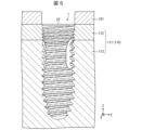
- FIG. 5 is a diagram showing a state in which the dental implant body 1 shown in FIG. 1 is implanted in the jawbone 110. As shown in FIG.
- the dental implant body 1 comprises a body portion 2 having a leading end portion 21 and a trailing end portion 22 .
- the distal end portion 21 is located on the cancellous bone 113 side of the alveolar bone 111 when the dental implant body 1 is embedded in the jawbone 110 .
- the rear end portion 22 is located on the cortical bone 112 side of the alveolar bone 111 when the dental implant body 1 is embedded in the jawbone 110 , and is located at the boundary between the alveolar bone 111 and the gingiva 101 .
- the body portion 2 includes a first region R1, a third region R3, and a second region R2, as shown in FIG.
- the first region R ⁇ b>1 is a tapered region including the tip portion 21 .
- the third region R3 is a region closer to the rear end portion 22 than the first region R1.
- the third region R3 is a columnar region of the body portion 2 that includes the rear end portion 22 .
- the third region R3 does not have to include the rear end portion 22 .
- the third region R3 may be configured such that its diameter increases from the bottom to the top.
- the second region R2 is a cylindrical region positioned between the first region R1 and the third region R3.
- the first region R1 and the second region R2 are regions in contact with the cancellous bone 113 when the dental implant body 1 is embedded in the jawbone 110, as shown in FIG.
- the third region R3 is a region in contact only with the cortical bone 112 when the dental implant body 1 is embedded in the jawbone 110, as shown in FIG. In this embodiment, the third region R3 is in contact with the gingiva 101 on the rear end portion 22 side.
- the body portion 2 further has a male screw portion 23.
- the male screw portion 23 is arranged from the first region R1 to the outer periphery of the third region R3.
- the male screw portion 23 spirally extends from the rear end portion 22 to the front end portion 21 .
- the dental implant body 1 can be screwed into the alveolar bone 111 by self-tapping and embedded.
- the clockwise direction with respect to the axis S1 passing through the center of rotation of the male threaded portion 23 corresponds to the direction in which the male threaded portion 23 is embedded, and the counterclockwise direction.
- the clockwise direction corresponds to the direction in which the male screw portion 23 is pulled out.
- the clockwise direction with respect to the axis S1 passing through the rotation center of the male threaded portion 23 corresponds to the direction in which the male threaded portion 23 is removed, and the counterclockwise direction corresponds to the male. It may correspond to the direction in which the screw portion 23 is embedded.
- FIG. 4 is a top view of the dental implant body 1 shown in FIG.
- the outer circumference of the third region R3 (see FIG. 1) is circular when viewed from above.
- the outer circumference of the third region R3 is circular even when viewed downward (in the direction of the axis S1 passing through the rotation center of the male screw portion 23).
- the axis S1 passing through the rotation center of the male screw portion 23 is an axis passing through between the front end portion 21 and the rear end portion 22 of the body portion 2, as shown in FIG. shall mean the axis that becomes the axis of rotation when That is, the outer circumference of the third region R3 is rotationally symmetrical with respect to the axis S1 passing through the rotation center of the male screw portion 23 from the front end portion 21 side to the rear end portion 22 . This facilitates removal of the dental implant body 1 firmly fixed to the jawbone 110 .
- the dental implant body 1 has a display 25 on the rear end portion 22 of the main body portion 2 to indicate the position of the recess 24 described later on the outer peripheral surface 230 .
- the concave portion 24 cannot be recognized and the position of the concave portion 24 cannot be known from the outside of the jawbone 110 . Since the dental implant body 1 has the display 25, the position of the concave portion 24 can be recognized from the outside even after being embedded in the jawbone 110, and the process for removing the fixation between the concave portion 24 and the jawbone 110 can be facilitated. can be done.
- the display 25 indicates the width of the recess 24 in the XY plane and is displayed on the rear end portion 22 of the main body 2 so as to follow the outer peripheral surface 230 .
- the display 25 is not limited to this as long as it indicates the position of the recess 24 on the outer peripheral surface 230 . In other words, the display 25 may indicate a part of the position of the recess 24 on the outer peripheral surface 230 .
- ⁇ Concave> 3 is a cross-sectional view taken along the line II of FIG. 1.
- the body portion 2 has a recess 24 .
- the recess 24 is formed by an end surface 241 perpendicular to the outer peripheral surface 230 and a surface 242 perpendicular to the end surface 241 .
- the end surface 241 forming the recess 24 and the surface 242 perpendicular to the end surface 241 form an inverted L shape when viewed from above.
- the shape of the concave portion 24 may be any shape that contributes to fixation after the dental implant body 1 is embedded in the jawbone 110 .
- the recess 24 has a groove-like shape, but it may be a hole.
- the recess 24 is arranged so as to be continuous only with the outer peripheral surface 230 of the male threaded portion 23 of the second region R2 and the male threaded portion 23 of the third region R3, excluding the vicinity of the first region R1. .
- the recessed portion 24 is not arranged on the outer peripheral surface 230 of the male screw portion 23 in the first region R1. According to this configuration, when removing the dental implant body 1, there is no need to use a tool to excise the bone around the regenerated bone in the recess 24 located near the first region R1. Therefore, removal of the dental implant body 1 can be facilitated.
- the concave portion 24 arranged on the outer peripheral surface 230 of the male screw portion 23 in the second region R2 and the concave portion 24 arranged in the outer peripheral surface 230 of the male screw portion 23 in the third region R3 may not be continuous. good.
- the recessed portion 24 may reach the rear end portion 22 of the outer peripheral surface 230 of the externally threaded portion 23 in the third region R3, but is arranged outside the rear end portion 22 in this embodiment.
- the rear end portion 22 of the dental implant body 1 With the dental implant body 1 embedded in the jawbone 110, the rear end portion 22 of the dental implant body 1 is positioned at the boundary between the bone tissue (the jawbone 110) and the soft tissue (the gingiva 101).
- the presence of the recess 24 in the rear end 22 may provide an infection route for oral bacteria into the jawbone 110 .
- By arranging the concave portion 24 at a position other than the rear end portion 22 it is possible to reduce the risk of becoming an infection route for the above-mentioned oral bacteria into the jawbone 110 .
- the recessed portion 24 may be arranged not only in the rear end portion 22 of the outer peripheral surface 230 of the male screw portion 23 in the third region R3, but also in areas other than the vicinity of the rear end portion 22. This makes it possible to further reduce the risk of becoming the infection route described above.
- the recessed portion 24 may be arranged only on the outer peripheral surface 230 of the male screw portion 23 in the second region R2. As a result, it is possible to further reduce the risk of the oral bacteria becoming an infection route into the jawbone 110 .
- three recesses 24 are arranged on the outer peripheral surface 230 .
- the number of recesses 24 may be singular. When the number of recesses 24 is plural, the number of recesses 24 is not limited to three as long as it is plural.
- the concave portion 24 is arranged at a rotationally symmetrical position with respect to the axis S1 passing through the rotation center of the male screw portion 23. As shown in FIG. In this embodiment, it is three-fold symmetrical with respect to the axis of the male screw portion 23 .
- the dental implant body 1 and the jawbone 110 can be fixed in a well-balanced manner.
- the positions of the recesses 24 can be changed according to the number of the recesses 24 arranged on the outer peripheral surface 230 .
- the concave portions 24 may be configured to have four-fold symmetry with respect to the axis of the male screw portion 23 .
- recesses 24 do not have to be arranged at positions that are rotationally symmetrical about axis S ⁇ b>1 passing through the center of rotation of male threaded portion 23 .
- the recesses 24 may be arranged along the direction of the axis S ⁇ b>1 passing through the rotation center of the male threaded portion 23 .
- the concave portion 24 has an end surface 241 along the direction of the axis S1 passing through the rotation center of the male screw portion 23. As shown in FIG.
- the recess 24 may not have the end surface 241 .
- the recess 24 has an end surface 241 on the counterclockwise side when viewed from above.
- the recessed portion 24 has a cutting edge portion 2411 .
- the cutting edge portion 2411 functions as a cutting edge when the male screw portion 23 is rotated about the axis S1 passing through the rotation center of the male screw portion 23 .
- the cutting edge portion 2411 makes it possible to enhance the cutting ability of the dental implant body 1 .
- the cutting edge 2411 can easily cut the regenerated bone in the recess 24 . Therefore, removal of the dental implant body 1 can be facilitated.
- the cutting edge portion 2411 is arranged on the thread of the male screw portion 23 of the end face 241 .
- at least a portion of the ridge formed by the intersection of the end surface 241 and the outer peripheral surface 230 of the male screw portion 23 serves as the cutting edge portion 2411 .
- the radius of curvature of this ridge may be 100 ⁇ m or less. Since the cutting edge 2411 is disposed on the thread of the end face 241 along the axis S1 passing through the center of rotation of the male threaded portion 23, the cutting edge 2411 can be efficiently used when the dental implant 1 is rotated. can do.
- the cutting edge portion 2411 may not be arranged on the end surface 241 and may be arranged on any one of the recesses 24 .
- the cutting edge portion 2411 does not have to be arranged in the concave portion 24 .
- the cutting edge portions 2411 may be arranged on the threads of the male screw portions of the two end faces 241, respectively. In this case, removal of the dental implant body 1 can also be facilitated.
- the first region R1 occupies one-eighth or more and two-thirds or less of the male screw portion 23 in the direction of the axis S1 passing through the rotation center of the male screw portion 23 . This allows the recess 24 to have an appropriate size. In the present embodiment, as shown in FIG. 1, the first region R1 extends 3/18 or more and 3/8 or less of the male screw portion 23 in the direction of the axis S1 passing through the rotation center of the male screw portion 23. Occupy The first region R1 does not have to occupy one-eighth or more and two-thirds or less of the male screw portion 23 in the direction of the axis S1 passing through the rotation center of the male screw portion 23 .
- FIG. 6 is a diagram showing a modification of the dental implant body 1 shown in FIG.
- Reference numeral 6001 in FIG. 6 is a front view of the dental implant body 1A.
- Reference numeral 6002 in FIG. 6 is a right side view of the dental implant body 1A.
- the concave portion 24A has an end surface 241A that is inclined with respect to the direction of the axis S1 (see FIG. 1) passing through the rotation center of the male screw portion 23, unlike the end surface 241 of the first embodiment. .
- the dental implant body 1A has the same effects as the dental implant body 1 in the first embodiment.
- the dental implant body 1A having the end face 241A inclined with respect to the direction of the axis S1 passing through the rotation center of the male screw portion 23 has the effect of reducing the resistance during implantation.
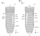
- FIG. 7 is a diagram showing still another modification of the dental implant body 1 shown in FIG.
- Reference numeral 7001 in FIG. 7 is a front view of the dental implant body 1B.
- Reference numeral 7002 in FIG. 7 is a right side view of the dental implant body 1B.
- the main body portion 2B differs from the main body portion 2 in that the outer peripheral surface 230 of the male threaded portion 23 of the second region R2 including the vicinity of the first region R1 and the male threaded portion 23 of the third region R3 is provided. It has recesses 24B that are arranged so as to be continuous only. In other words, the recessed portion 24B is arranged on the outer peripheral surface 230 of the male screw portion 23 in the second region R2 up to the upper end portion of the first region R1. This makes it easier for the cutting edge 2411B to cut the alveolar bone 111 clockwise when the dental implant body 1B is embedded in the jawbone 110 .
- FIG. 8 is a diagram showing a modification of the dental implant body 1B shown in FIG.
- Reference numeral 8001 in FIG. 8 is a front view of the dental implant body 1C.
- Reference numeral 8002 in FIG. 8 is a right side view of the dental implant body 1C.
- a dental implant body 1C shown in FIG. 8 is different from the dental implant body 1A shown in FIG. 6 in that the recess 24C is arranged on the outer peripheral surface 230 of the male screw portion 23 in the second region R2 up to the upper end of the first region R1. The difference is that
- the concave portion 24C has an end surface 241C that is inclined with respect to the direction of the axis S1 (see FIG. 1) passing through the rotation center of the male screw portion 23, unlike the end surface 241B.
- the dental implant body 1C is embedded in the jawbone 110, the resistance due to the contact area between the end surface 241C and the alveolar bone 111 in the direction of the axis S1 (see FIG. 1) passing through the rotation center of the male screw portion 23 can be reduced. .
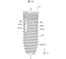
- FIG. 9 is a front view showing a dental implant body 1D according to Embodiment 2 of the present disclosure. 10 is a right side view of the dental implant body 1D shown in FIG. 9. FIG. 11 is a cross-sectional view taken along the line IX-IX in FIG. 9. FIG.
- the recess 24D has an end surface 241D on the counterclockwise direction side when viewed from above.
- the cutting edge portion 2411D has a shape that functions as a cutting edge when rotated in the counterclockwise direction (the direction in which the male screw portion 23 is pulled out).
- the recess 24D is formed by an end surface 241D perpendicular to the outer peripheral surface 230 and a surface 242D perpendicular to the end surface 241D.
- the end surface 241D forming the recess 24 and the surface perpendicular to the end surface 241D form an L shape when viewed from above.
- the cutting edge portion 2411D is arranged in the extraction direction for extracting the male screw portion 23, extraction of the dental implant body 1D can be facilitated.
- the direction in which the male screw portion 23 is pulled out may be the clockwise direction. In this case, the counterclockwise direction is the direction for embedding the male screw portion 23 into the jawbone 110 .
- FIG. 12A and 12B are diagrams illustrating a method of extracting the dental implant body 1D shown in FIG. 9 from the jawbone 110.
- FIG. FIG. 13 is a diagram showing a conventional dental implant body 1E.
- the dental implant body 1E includes a recess 24E arranged only on the outer peripheral surface 230 of the male threaded portion 23 of the first region R1.
- a space is formed between the recess 24E and the alveolar bone 111 when the dental implant body 1E is implanted in the alveolar bone 111 .
- the jawbone 110 is regenerated to fill the concave portion 24E. 12 when removing the dental implant body 1E from the jawbone 110, the jawbone 110 is shaved with a tool from above to below the outside of the display 25 to the vicinity of the concave portion 24E. Then, by rotating the dental implant body 1E counterclockwise, the dental implant body 1E is removed from the jawbone 110 while scraping the jawbone 110 in the concave portion 24E.
- the jawbone 110 is shaved with a tool to the vicinity of 24D. In other words, there is no need to cut the jawbone 110 with a tool from above to below the outside of the display 25 to the vicinity of the distal end portion 21 of the dental implant body 1D. Therefore, the dental implant body 1D firmly fixed to the jawbone 110 can be removed more easily than the dental implant body 1E. Also, damage to the jawbone 110 is less than when the dental implant body 1E is removed from the jawbone 110 . Moreover, the operation time for extracting the dental implant body 1D from the jawbone 110 can be shortened.
- the dental implant body 1D is removed from the jawbone 110 while scraping the jawbone 110 in the concave portion 24D.
- the dental implant body 1D has no concave portion 24D in the tapered distal end portion 21 and has a rotationally symmetrical shape up to the rear end portion 22 (see FIGS. 9 to 11). Removal of the implant body 1D can be facilitated.
Abstract
This dental implant body comprises a main body part that has a tip end part and a rear end part. The main body part is provided with a tapered first region that includes the tip end part, a third region that is closer to the rear end part than the first region, and a cylindrical second region that is positioned between the first region and the third region; has a male screw part that is disposed along the outer periphery of the first region and the third region; and is provided with a recess that is disposed only on the outer peripheral surface of the male screw part in the second region and the male screw part in the third region. The outer periphery of the third region is circular in a view from the axial direction which passes through the rotational center of the male screw part.
Description
本開示は歯科インプラント体に関する。
The present disclosure relates to dental implant bodies.
歯科インプラント体(歯科用インプラントフィクスチャー)が知られている。例えば特許文献1には、セルフタップのための切刃部が設けられた歯科用スクリュー型インプラント体が開示されている。切刃部は、歯科用スクリュー型インプラント体の下端、即ち顎骨に埋植する際に最も深い位置となる端部に設けられている。
A dental implant body (dental implant fixture) is known. For example, Patent Literature 1 discloses a dental screw-type implant body provided with a cutting edge for self-tapping. The cutting edge is provided at the lower end of the dental screw-type implant body, that is, at the deepest end when implanted in the jawbone.
また、例えば特許文献2には、顎骨への一次及び二次固定のために、偏心パラメータによって特徴づけられる非円筒形状のインプラント体が開示されている。偏心パラメータは、インプラント容積の断面が、その中心からこの断面の輪郭までの最小距離に対する、その中心からこの断面の輪郭までの最大距離の比率として定義される。特許文献2には、切刃部である切削溝を歯冠ゾーン、移行ゾーン、歯根尖端のいずれか、または、複数個所に備える歯科インプラント体が開示されている。
Also, for example, Patent Document 2 discloses a non-cylindrical implant body characterized by an eccentricity parameter for primary and secondary fixation to the jawbone. The eccentricity parameter is defined as the ratio of the maximum distance from the center of a cross section of the implant volume to the minimum distance from its center to the contour of this cross section. Patent Literature 2 discloses a dental implant body having cutting grooves, which are cutting edge portions, in any one of the crown zone, the transition zone, and the root apex, or in a plurality of places.
本開示の一態様に係る歯科インプラント体は、先端部および後端部を有する本体部を備え、前記本体部は先端部を含むテーパ形状の第1領域と、前記第1領域よりも後端部に近い第3領域と、前記第1領域と前記第3領域との間に位置する円柱状の第2領域とを備え、前記第1領域から前記第3領域の外周にわたって配された雄ネジ部を有し、前記第2領域の前記雄ネジ部の外周面にのみ配された凹部、または、前記第2領域の前記雄ネジ部と前記第3領域の前記雄ネジ部との外周面にのみ配された凹部、を備え、前記第3領域の外周は、前記雄ネジ部の回転中心を通る軸方向から見て円形である。
A dental implant body according to one aspect of the present disclosure includes a body portion having a distal end portion and a posterior end portion, the body portion having a tapered first region including a distal end portion and a tapered first region having a posterior end portion that is greater than the first region. and a cylindrical second region located between the first region and the third region, and a male screw portion arranged from the first region to the outer circumference of the third region and a recess arranged only on the outer peripheral surface of the male threaded portion of the second region, or only on the outer peripheral surface of the male threaded portion of the second region and the male threaded portion of the third region The outer circumference of the third region is circular when viewed from the axial direction passing through the center of rotation of the male threaded portion.
歯科インプラント体は、顎骨に埋植することにより、失われた歯根の機能を再建する生体埋植部材である。そのため、歯科インプラント体は顎骨と強固に一体化するよう、材質、形状、または表面性状が工夫されている。しかし稀に、歯科インプラント体は、何らかの原因により、抜去しなければならない場合がある。そのような場合、歯科医師は、歯科インプラント体が顎骨と強固に一体化しているため、歯科インプラント体の抜去に難渋することがあった。
A dental implant body is a biological implant that restores the function of the lost tooth root by being implanted in the jawbone. Therefore, the material, shape, and surface properties of the dental implant body are devised so that it can be firmly integrated with the jawbone. However, on rare occasions, the dental implant must be removed for some reason. In such cases, dentists sometimes find it difficult to remove the dental implant because the dental implant is firmly integrated with the jawbone.
本開示の一態様は、抜去の手間を軽減できる形状の歯科用インプラント体を提供することを目的とする。
An object of one aspect of the present disclosure is to provide a dental implant body having a shape that can reduce the trouble of removing it.
本開示の一態様によれば、抜去の手間を軽減できる形状の歯科用インプラント体を提供できる。
According to one aspect of the present disclosure, it is possible to provide a dental implant body having a shape that can reduce the time and effort required for removal.
〔実施形態1〕
以下、本開示の一実施形態について、図1~図8を参照して詳細に説明する。図1において、歯科インプラント体1の延伸方向をZ軸方向、歯科インプラント体1の左右方向をY軸方向、Y軸方向およびZ軸方向の両方に直交する方向をX軸方向とする。X軸正方向が奥方向である。Y軸正方向が右方向である。Z軸正方向が上方向である。図1で定義したX軸方向、Y軸方向およびZ軸方向は、他の図においても適用されるものとする。また、「平面」との記載は、視認できるレベルにおいて平面であればよく、厳密に平面であることを求めない。また、「垂直」との記載は、視認できるレベルにおいて垂直であればよく、厳密に垂直であることを求めない。 [Embodiment 1]
An embodiment of the present disclosure will be described in detail below with reference to FIGS. 1 to 8. FIG. In FIG. 1, the extending direction of thedental implant body 1 is the Z-axis direction, the horizontal direction of the dental implant body 1 is the Y-axis direction, and the direction orthogonal to both the Y-axis direction and the Z-axis direction is the X-axis direction. The positive direction of the X-axis is the depth direction. The positive direction of the Y-axis is the right direction. The positive direction of the Z-axis is the upward direction. The X-axis direction, Y-axis direction and Z-axis direction defined in FIG. 1 are also applied to other drawings. In addition, the term “flat surface” does not strictly require a flat surface as long as it is flat at a visible level. In addition, the description of "perpendicular" does not require that it is strictly perpendicular as long as it is perpendicular at a visible level.
以下、本開示の一実施形態について、図1~図8を参照して詳細に説明する。図1において、歯科インプラント体1の延伸方向をZ軸方向、歯科インプラント体1の左右方向をY軸方向、Y軸方向およびZ軸方向の両方に直交する方向をX軸方向とする。X軸正方向が奥方向である。Y軸正方向が右方向である。Z軸正方向が上方向である。図1で定義したX軸方向、Y軸方向およびZ軸方向は、他の図においても適用されるものとする。また、「平面」との記載は、視認できるレベルにおいて平面であればよく、厳密に平面であることを求めない。また、「垂直」との記載は、視認できるレベルにおいて垂直であればよく、厳密に垂直であることを求めない。 [Embodiment 1]
An embodiment of the present disclosure will be described in detail below with reference to FIGS. 1 to 8. FIG. In FIG. 1, the extending direction of the
<歯科インプラント体>
図1は、本開示の実施形態1に係る歯科インプラント体1を示す正面図である。図2は、図1に示す歯科インプラント体1の右側面図である。図5は、図1に示す歯科インプラント体1が顎骨110に埋植されている状態を示す図である。 <Dental implant body>
FIG. 1 is a front view showing adental implant body 1 according to Embodiment 1 of the present disclosure. FIG. 2 is a right side view of the dental implant body 1 shown in FIG. FIG. 5 is a diagram showing a state in which the dental implant body 1 shown in FIG. 1 is implanted in the jawbone 110. As shown in FIG.
図1は、本開示の実施形態1に係る歯科インプラント体1を示す正面図である。図2は、図1に示す歯科インプラント体1の右側面図である。図5は、図1に示す歯科インプラント体1が顎骨110に埋植されている状態を示す図である。 <Dental implant body>
FIG. 1 is a front view showing a
図1および図2に示すように、歯科インプラント体1は、先端部21および後端部22を有する本体部2を備える。先端部21は、図5に示すように、歯科インプラント体1が顎骨110に埋入されている状態において、歯槽骨111の海綿骨113側に位置する部位である。後端部22は、歯科インプラント体1が顎骨110に埋入されている状態において、歯槽骨111の皮質骨112側に位置する部位であり、歯槽骨111と歯肉101との境界に位置する。
As shown in FIGS. 1 and 2, the dental implant body 1 comprises a body portion 2 having a leading end portion 21 and a trailing end portion 22 . As shown in FIG. 5 , the distal end portion 21 is located on the cancellous bone 113 side of the alveolar bone 111 when the dental implant body 1 is embedded in the jawbone 110 . The rear end portion 22 is located on the cortical bone 112 side of the alveolar bone 111 when the dental implant body 1 is embedded in the jawbone 110 , and is located at the boundary between the alveolar bone 111 and the gingiva 101 .
本体部2は、図1に示すように、第1領域R1と、第3領域R3と、第2領域R2とを備える。第1領域R1は、先端部21を含むテーパ形状の領域である。第3領域R3は、第1領域R1よりも後端部22に近い領域である。本実施形態では、第3領域R3は、本体部2のうち後端部22を含む円柱状の領域である。第3領域R3は、後端部22を含まなくてもよい。第3領域R3は、下方向から上方向に向かうにつれて大径になるように構成されていてもよい。
The body portion 2 includes a first region R1, a third region R3, and a second region R2, as shown in FIG. The first region R<b>1 is a tapered region including the tip portion 21 . The third region R3 is a region closer to the rear end portion 22 than the first region R1. In the present embodiment, the third region R3 is a columnar region of the body portion 2 that includes the rear end portion 22 . The third region R3 does not have to include the rear end portion 22 . The third region R3 may be configured such that its diameter increases from the bottom to the top.
第2領域R2は、第1領域R1と第3領域R3との間に位置する円柱状の領域である。第1領域R1および第2領域R2は、図5に示すように、歯科インプラント体1が顎骨110に埋入されている状態において、海綿骨113に接している領域である。第3領域R3は、図5に示すように、歯科インプラント体1が顎骨110に埋入されている状態において、皮質骨112のみに接している領域である。本実施形態では、第3領域R3は、後端部22側において歯肉101と接している。
The second region R2 is a cylindrical region positioned between the first region R1 and the third region R3. The first region R1 and the second region R2 are regions in contact with the cancellous bone 113 when the dental implant body 1 is embedded in the jawbone 110, as shown in FIG. The third region R3 is a region in contact only with the cortical bone 112 when the dental implant body 1 is embedded in the jawbone 110, as shown in FIG. In this embodiment, the third region R3 is in contact with the gingiva 101 on the rear end portion 22 side.
図1および図2に示すように、本体部2は、雄ネジ部23をさらに有する。雄ネジ部23は、第1領域R1から第3領域R3の外周にわたって配されている。雄ネジ部23は、後端部22から先端部21にわたって螺旋状に延びている。これにより、歯科インプラント体1を歯槽骨111にセルフタップで螺入しつつ埋入することができる。本実施形態では、歯科インプラント体1を上方向からみた状態において、雄ネジ部23の回転中心を通る軸S1に対して時計回りの方向が雄ネジ部23を埋入する方向に対応し、反時計回りの方向が雄ネジ部23を抜去する方向に対応する。歯科インプラント体1を上方向からみた状態において、雄ネジ部23の回転中心を通る軸S1に対して時計回りの方向が雄ネジ部23を抜去する方向に対応し、反時計回りの方向が雄ネジ部23を埋入する方向に対応してもよい。
As shown in FIGS. 1 and 2, the body portion 2 further has a male screw portion 23. The male screw portion 23 is arranged from the first region R1 to the outer periphery of the third region R3. The male screw portion 23 spirally extends from the rear end portion 22 to the front end portion 21 . As a result, the dental implant body 1 can be screwed into the alveolar bone 111 by self-tapping and embedded. In the present embodiment, when the dental implant body 1 is viewed from above, the clockwise direction with respect to the axis S1 passing through the center of rotation of the male threaded portion 23 corresponds to the direction in which the male threaded portion 23 is embedded, and the counterclockwise direction. The clockwise direction corresponds to the direction in which the male screw portion 23 is pulled out. When the dental implant body 1 is viewed from above, the clockwise direction with respect to the axis S1 passing through the rotation center of the male threaded portion 23 corresponds to the direction in which the male threaded portion 23 is removed, and the counterclockwise direction corresponds to the male. It may correspond to the direction in which the screw portion 23 is embedded.
図4は、図1に示す歯科インプラント体1の上面図である。図4に示すように、第3領域R3(図1参照)の外周は、上方向からみて円形である。本実施形態では、第3領域R3は円柱状であるため、第3領域R3の外周は、下方向(雄ネジ部23の回転中心を通る軸S1方向)からみても円形である。
FIG. 4 is a top view of the dental implant body 1 shown in FIG. As shown in FIG. 4, the outer circumference of the third region R3 (see FIG. 1) is circular when viewed from above. In the present embodiment, since the third region R3 is columnar, the outer circumference of the third region R3 is circular even when viewed downward (in the direction of the axis S1 passing through the rotation center of the male screw portion 23).
ここで、雄ネジ部23の回転中心を通る軸S1とは、図1に示すように、本体部2の先端部21および後端部22の間を貫く軸であり、歯科インプラント体1を回転させたときに回転軸となる軸を意味するものとする。つまり、第3領域R3の外周は、先端部21側から後端部22まで雄ネジ部23の回転中心を通る軸S1に対して回転対称形状である。これにより、顎骨110に強固に固定された歯科インプラント体1の抜去を容易にすることができる。
Here, the axis S1 passing through the rotation center of the male screw portion 23 is an axis passing through between the front end portion 21 and the rear end portion 22 of the body portion 2, as shown in FIG. shall mean the axis that becomes the axis of rotation when That is, the outer circumference of the third region R3 is rotationally symmetrical with respect to the axis S1 passing through the rotation center of the male screw portion 23 from the front end portion 21 side to the rear end portion 22 . This facilitates removal of the dental implant body 1 firmly fixed to the jawbone 110 .
図4に示すように、歯科インプラント体1は、本体部2の後端部22に、外周面230における後述する凹部24が配された位置を示す表示25を持つ。歯科インプラント体1が顎骨110に埋入された後、凹部24を認識することができず、顎骨110の外部からは凹部24の位置が分からない。歯科インプラント体1が表示25を持つことにより、顎骨110に埋入後も外部から凹部24の位置を認識することができ、凹部24と顎骨110との固着を剥がすための処理を容易にすることができる。本実施形態では、表示25は、XY平面において凹部24の幅を示し、かつ外周面230に沿うように、本体部2の後端部22に表示されている。表示25は、外周面230における凹部24が配された位置を示す態様であればこれに限られない。換言すれば、表示25は、外周面230における凹部24が配された位置の一部を示す態様でもよい。
As shown in FIG. 4, the dental implant body 1 has a display 25 on the rear end portion 22 of the main body portion 2 to indicate the position of the recess 24 described later on the outer peripheral surface 230 . After the dental implant body 1 is embedded in the jawbone 110 , the concave portion 24 cannot be recognized and the position of the concave portion 24 cannot be known from the outside of the jawbone 110 . Since the dental implant body 1 has the display 25, the position of the concave portion 24 can be recognized from the outside even after being embedded in the jawbone 110, and the process for removing the fixation between the concave portion 24 and the jawbone 110 can be facilitated. can be done. In this embodiment, the display 25 indicates the width of the recess 24 in the XY plane and is displayed on the rear end portion 22 of the main body 2 so as to follow the outer peripheral surface 230 . The display 25 is not limited to this as long as it indicates the position of the recess 24 on the outer peripheral surface 230 . In other words, the display 25 may indicate a part of the position of the recess 24 on the outer peripheral surface 230 .
<凹部>
図3は、図1のI-I線矢視断面図である。図3に示すように、本体部2は、凹部24を備える。本実施形態では、凹部24は、外周面230に対して垂直な端面241と、該端面241に垂直な面242とにより形成されている。換言すれば、凹部24を構成する端面241と該端面241に垂直な面242とは、上方向から視て逆L字状をなす。凹部24の形状は、歯科インプラント体1を顎骨110に埋入した後に固定性に寄与するものであればよい。本実施形態では、凹部24は溝のような形状を有しているが孔でもよい。 <Concave>
3 is a cross-sectional view taken along the line II of FIG. 1. FIG. As shown in FIG. 3 , thebody portion 2 has a recess 24 . In this embodiment, the recess 24 is formed by an end surface 241 perpendicular to the outer peripheral surface 230 and a surface 242 perpendicular to the end surface 241 . In other words, the end surface 241 forming the recess 24 and the surface 242 perpendicular to the end surface 241 form an inverted L shape when viewed from above. The shape of the concave portion 24 may be any shape that contributes to fixation after the dental implant body 1 is embedded in the jawbone 110 . In this embodiment, the recess 24 has a groove-like shape, but it may be a hole.
図3は、図1のI-I線矢視断面図である。図3に示すように、本体部2は、凹部24を備える。本実施形態では、凹部24は、外周面230に対して垂直な端面241と、該端面241に垂直な面242とにより形成されている。換言すれば、凹部24を構成する端面241と該端面241に垂直な面242とは、上方向から視て逆L字状をなす。凹部24の形状は、歯科インプラント体1を顎骨110に埋入した後に固定性に寄与するものであればよい。本実施形態では、凹部24は溝のような形状を有しているが孔でもよい。 <Concave>
3 is a cross-sectional view taken along the line II of FIG. 1. FIG. As shown in FIG. 3 , the
本実施形態では、凹部24は、第1領域R1近傍を除く第2領域R2の雄ネジ部23と第3領域R3の雄ネジ部23との外周面230にのみ連続するように配されている。換言すれば、凹部24は第1領域R1の雄ネジ部23の外周面230には配されていない。この構成によれば、歯科インプラント体1を抜去する際に、第1領域R1近傍に位置する凹部24内の再生骨の周囲の骨を工具により切除する必要性が無くなる。このため、歯科インプラント体1の抜去を容易にすることができる。第2領域R2の雄ネジ部23の外周面230に配された凹部24と、第3領域R3の雄ネジ部23の外周面230に配された凹部24と、は、連続していなくてもよい。
In this embodiment, the recess 24 is arranged so as to be continuous only with the outer peripheral surface 230 of the male threaded portion 23 of the second region R2 and the male threaded portion 23 of the third region R3, excluding the vicinity of the first region R1. . In other words, the recessed portion 24 is not arranged on the outer peripheral surface 230 of the male screw portion 23 in the first region R1. According to this configuration, when removing the dental implant body 1, there is no need to use a tool to excise the bone around the regenerated bone in the recess 24 located near the first region R1. Therefore, removal of the dental implant body 1 can be facilitated. The concave portion 24 arranged on the outer peripheral surface 230 of the male screw portion 23 in the second region R2 and the concave portion 24 arranged in the outer peripheral surface 230 of the male screw portion 23 in the third region R3 may not be continuous. good.
凹部24は、第3領域R3の雄ネジ部23の外周面230のうち後端部22に達していてもよいが、本実施形態では後端部22以外に配されている。歯科インプラント体1が顎骨110に埋入されている状態において、歯科インプラント体1の後端部22は、骨組織(顎骨110)と軟組織(歯肉101)との境界に位置する。しかし、後端部22に凹部24があると、口内細菌の顎骨110内への感染経路となるおそれがある。凹部24を後端部22以外に配することにより、上記の口内細菌の顎骨110内への感染経路となるおそれを低減できる。
The recessed portion 24 may reach the rear end portion 22 of the outer peripheral surface 230 of the externally threaded portion 23 in the third region R3, but is arranged outside the rear end portion 22 in this embodiment. With the dental implant body 1 embedded in the jawbone 110, the rear end portion 22 of the dental implant body 1 is positioned at the boundary between the bone tissue (the jawbone 110) and the soft tissue (the gingiva 101). However, the presence of the recess 24 in the rear end 22 may provide an infection route for oral bacteria into the jawbone 110 . By arranging the concave portion 24 at a position other than the rear end portion 22 , it is possible to reduce the risk of becoming an infection route for the above-mentioned oral bacteria into the jawbone 110 .
凹部24は、第3領域R3の雄ネジ部23の外周面230のうち後端部22だけでなく、後端部22近傍以外に配されていてもよい。これにより、上記感染経路となるおそれをより低減できる。
The recessed portion 24 may be arranged not only in the rear end portion 22 of the outer peripheral surface 230 of the male screw portion 23 in the third region R3, but also in areas other than the vicinity of the rear end portion 22. This makes it possible to further reduce the risk of becoming the infection route described above.
凹部24は、第2領域R2の雄ネジ部23の外周面230にのみ配されていてもよい。これにより、口内細菌の顎骨110内への感染経路となるおそれをより低減できる。
The recessed portion 24 may be arranged only on the outer peripheral surface 230 of the male screw portion 23 in the second region R2. As a result, it is possible to further reduce the risk of the oral bacteria becoming an infection route into the jawbone 110 .
図3に示すように、凹部24は、外周面230に3つ配されている。凹部24を外周面230に複数配することにより、歯科インプラント体1と顎骨110との固着をより強固にすることができる。凹部24の数は、単数であってもよい。凹部24の数が複数である場合、凹部24の数は複数であれば3つに限られない。
As shown in FIG. 3 , three recesses 24 are arranged on the outer peripheral surface 230 . By arranging a plurality of recesses 24 on the outer peripheral surface 230, the fixation between the dental implant body 1 and the jawbone 110 can be made stronger. The number of recesses 24 may be singular. When the number of recesses 24 is plural, the number of recesses 24 is not limited to three as long as it is plural.
図3に示すように、凹部24は、雄ネジ部23の回転中心を通る軸S1に対して回転対称となる位置に配されている。本実施形態では、雄ネジ部23の軸に対して3回対称となっている。凹部24を回転対称に配することにより、歯科インプラント体1と顎骨110とをバランスよく固着させることができる。凹部24の位置は、外周面230に配される凹部24の数に応じて変更できる。例えば、凹部24の数が4つの場合には、雄ネジ部23の軸に対して4回対称となるように構成されていてもよい。凹部24が外周面230に複数配されている場合に、凹部24は、雄ネジ部23の回転中心を通る軸S1に対して回転対象となる位置に配されていなくてもよい。また、凹部24の数が複数である場合、それら凹部24は雄ネジ部23の回転中心を通る軸S1方向に沿って配置されていてもよい。
As shown in FIG. 3, the concave portion 24 is arranged at a rotationally symmetrical position with respect to the axis S1 passing through the rotation center of the male screw portion 23. As shown in FIG. In this embodiment, it is three-fold symmetrical with respect to the axis of the male screw portion 23 . By arranging the concave portions 24 rotationally symmetrically, the dental implant body 1 and the jawbone 110 can be fixed in a well-balanced manner. The positions of the recesses 24 can be changed according to the number of the recesses 24 arranged on the outer peripheral surface 230 . For example, when the number of concave portions 24 is four, the concave portions 24 may be configured to have four-fold symmetry with respect to the axis of the male screw portion 23 . When a plurality of recesses 24 are arranged on outer peripheral surface 230 , recesses 24 do not have to be arranged at positions that are rotationally symmetrical about axis S<b>1 passing through the center of rotation of male threaded portion 23 . Moreover, when the number of the recesses 24 is plural, the recesses 24 may be arranged along the direction of the axis S<b>1 passing through the rotation center of the male threaded portion 23 .
図1~図3に示すように、凹部24は、雄ネジ部23の回転中心を通る軸S1方向に沿った端面241を有している。凹部24は、端面241を有していなくてもよい。本実施形態では、凹部24は、上方向からみたときに、反時計回り方向側に端面241を有している。
As shown in FIGS. 1 to 3, the concave portion 24 has an end surface 241 along the direction of the axis S1 passing through the rotation center of the male screw portion 23. As shown in FIG. The recess 24 may not have the end surface 241 . In this embodiment, the recess 24 has an end surface 241 on the counterclockwise side when viewed from above.
凹部24は切刃部2411を備えている。ここで、切刃部2411とは、雄ネジ部23を雄ネジ部23の回転中心を通る軸S1に対して回転させた際に切刃として機能するものである。換言すれば、切刃部2411は、歯科インプラント体1の切削能力の強化を可能にするものである。これにより、歯科インプラント体1を顎骨110から抜去する際に、切刃部2411が凹部24内の再生骨を切削しやすくなる。このため、歯科インプラント体1の抜去を容易にすることができる。
The recessed portion 24 has a cutting edge portion 2411 . Here, the cutting edge portion 2411 functions as a cutting edge when the male screw portion 23 is rotated about the axis S1 passing through the rotation center of the male screw portion 23 . In other words, the cutting edge portion 2411 makes it possible to enhance the cutting ability of the dental implant body 1 . As a result, when the dental implant body 1 is removed from the jawbone 110 , the cutting edge 2411 can easily cut the regenerated bone in the recess 24 . Therefore, removal of the dental implant body 1 can be facilitated.
本実施形態では、切刃部2411は、端面241の雄ネジ部23のネジ山に配されている。換言すれば、端面241と雄ネジ部23の外周面230とが交わることにより形成される稜部の少なくとも一部が切刃部2411となる。この稜部の曲率半径は、100μm以下であってもよい。切刃部2411が、雄ネジ部23の回転中心を通る軸S1に沿った端面241のネジ山に配されているので、歯科インプラント1を回転させるときに、切刃部2411を効率的に使用することができる。切刃部2411は、端面241に配されていなくても良く、凹部24のいずれかに配されていてもよい。切刃部2411は、凹部24に配されていなくてもよい。凹部24が外周面230に対して垂直な2つの端面241により形成されている場合、切刃部2411は、2つの端面241の雄ネジ部のネジ山にそれぞれ配されていてもよい。この場合、歯科インプラント体1の抜去も容易にすることができる。
In this embodiment, the cutting edge portion 2411 is arranged on the thread of the male screw portion 23 of the end face 241 . In other words, at least a portion of the ridge formed by the intersection of the end surface 241 and the outer peripheral surface 230 of the male screw portion 23 serves as the cutting edge portion 2411 . The radius of curvature of this ridge may be 100 μm or less. Since the cutting edge 2411 is disposed on the thread of the end face 241 along the axis S1 passing through the center of rotation of the male threaded portion 23, the cutting edge 2411 can be efficiently used when the dental implant 1 is rotated. can do. The cutting edge portion 2411 may not be arranged on the end surface 241 and may be arranged on any one of the recesses 24 . The cutting edge portion 2411 does not have to be arranged in the concave portion 24 . When the recessed portion 24 is formed by two end faces 241 perpendicular to the outer peripheral surface 230, the cutting edge portions 2411 may be arranged on the threads of the male screw portions of the two end faces 241, respectively. In this case, removal of the dental implant body 1 can also be facilitated.
第1領域R1は、雄ネジ部23の回転中心を通る軸S1方向において、雄ネジ部23の8分の1以上、かつ3分の2以下を占める。これにより、凹部24を適切な大きさとすることができる。本実施形態では、図1に示すように、第1領域R1は、雄ネジ部23の回転中心を通る軸S1方向において、雄ネジ部23の18分の3以上、かつ8分の3以下を占める。第1領域R1は、雄ネジ部23の回転中心を通る軸S1方向において、雄ネジ部23の8分の1以上、かつ3分の2以下を占めていなくてもよい。
The first region R1 occupies one-eighth or more and two-thirds or less of the male screw portion 23 in the direction of the axis S1 passing through the rotation center of the male screw portion 23 . This allows the recess 24 to have an appropriate size. In the present embodiment, as shown in FIG. 1, the first region R1 extends 3/18 or more and 3/8 or less of the male screw portion 23 in the direction of the axis S1 passing through the rotation center of the male screw portion 23. Occupy The first region R1 does not have to occupy one-eighth or more and two-thirds or less of the male screw portion 23 in the direction of the axis S1 passing through the rotation center of the male screw portion 23 .
<変形例>
本実施形態の変形例について、図6~図8を用いて説明すれば、以下のとおりである。説明の便宜上、上記実施形態1にて説明した部材と同じ機能を有する部材については、同じ符号を付記し、その説明を省略することがある。 <Modification>
Modifications of this embodiment will be described below with reference to FIGS. 6 to 8. FIG. For convenience of description, members having the same functions as those of the members described in the first embodiment are denoted by the same reference numerals, and their description may be omitted.
図6は、図1に示す歯科インプラント体1の変形例を示す図である。図6の符号6001は、歯科インプラント体1Aの正面図である。図6の符号6002は、歯科インプラント体1Aの右側面図である。
FIG. 6 is a diagram showing a modification of the dental implant body 1 shown in FIG. Reference numeral 6001 in FIG. 6 is a front view of the dental implant body 1A. Reference numeral 6002 in FIG. 6 is a right side view of the dental implant body 1A.
図6に示すように、凹部24Aは、実施形態1の端面241と異なり雄ネジ部23の回転中心を通る軸S1方向(図1参照)に対して傾斜するような端面241Aを有している。このような構成においても、歯科インプラント体1Aは、実施形態1における歯科インプラント体1と同様の効果を奏する。さらに、雄ネジ部23の回転中心を通る軸S1方向に対して傾斜するような端面241Aを有している歯科インプラント体1Aは、埋入時の抵抗を低減できるという効果を奏する。
As shown in FIG. 6, the concave portion 24A has an end surface 241A that is inclined with respect to the direction of the axis S1 (see FIG. 1) passing through the rotation center of the male screw portion 23, unlike the end surface 241 of the first embodiment. . Even with such a configuration, the dental implant body 1A has the same effects as the dental implant body 1 in the first embodiment. Furthermore, the dental implant body 1A having the end face 241A inclined with respect to the direction of the axis S1 passing through the rotation center of the male screw portion 23 has the effect of reducing the resistance during implantation.
図7は、図1に示す歯科インプラント体1の更に別の変形例を示す図である。図7の符号7001は、歯科インプラント体1Bの正面図である。図7の符号7002は、歯科インプラント体1Bの右側面図である。
FIG. 7 is a diagram showing still another modification of the dental implant body 1 shown in FIG. Reference numeral 7001 in FIG. 7 is a front view of the dental implant body 1B. Reference numeral 7002 in FIG. 7 is a right side view of the dental implant body 1B.
図7に示すように、本体部2Bは、本体部2と異なり、第1領域R1近傍を含む第2領域R2の雄ネジ部23と第3領域R3の雄ネジ部23との外周面230にのみ連続するように配された凹部24Bを備える。換言すれば、凹部24Bは、第1領域R1の上端部まで第2領域R2の雄ネジ部23の外周面230に配されている。これにより、歯科インプラント体1Bを顎骨110に埋入の際に、切刃部2411Bが時計回りに方向に向かって歯槽骨111を削ることが容易となる。
As shown in FIG. 7, the main body portion 2B differs from the main body portion 2 in that the outer peripheral surface 230 of the male threaded portion 23 of the second region R2 including the vicinity of the first region R1 and the male threaded portion 23 of the third region R3 is provided. It has recesses 24B that are arranged so as to be continuous only. In other words, the recessed portion 24B is arranged on the outer peripheral surface 230 of the male screw portion 23 in the second region R2 up to the upper end portion of the first region R1. This makes it easier for the cutting edge 2411B to cut the alveolar bone 111 clockwise when the dental implant body 1B is embedded in the jawbone 110 .
図8は、図7に示す歯科インプラント体1Bの変形例を示す図である。図8の符号8001は、歯科インプラント体1Cの正面図である。図8の符号8002は、歯科インプラント体1Cの右側面図である。図8に示す歯科インプラント体1Cは、図6に示す歯科インプラント体1Aと比べて、凹部24Cが、第1領域R1の上端部まで第2領域R2の雄ネジ部23の外周面230に配されている点が異なっている。
FIG. 8 is a diagram showing a modification of the dental implant body 1B shown in FIG. Reference numeral 8001 in FIG. 8 is a front view of the dental implant body 1C. Reference numeral 8002 in FIG. 8 is a right side view of the dental implant body 1C. A dental implant body 1C shown in FIG. 8 is different from the dental implant body 1A shown in FIG. 6 in that the recess 24C is arranged on the outer peripheral surface 230 of the male screw portion 23 in the second region R2 up to the upper end of the first region R1. The difference is that
図8に示すように、凹部24Cは、端面241Bと異なり雄ネジ部23の回転中心を通る軸S1方向(図1参照)に対して傾斜するような端面241Cを有している。これにより、歯科インプラント体1Cを顎骨110に埋入の際に、雄ネジ部23の回転中心を通る軸S1方向(図1参照)における端面241Cと歯槽骨111との接触面積による抵抗を低減できる。
As shown in FIG. 8, the concave portion 24C has an end surface 241C that is inclined with respect to the direction of the axis S1 (see FIG. 1) passing through the rotation center of the male screw portion 23, unlike the end surface 241B. As a result, when the dental implant body 1C is embedded in the jawbone 110, the resistance due to the contact area between the end surface 241C and the alveolar bone 111 in the direction of the axis S1 (see FIG. 1) passing through the rotation center of the male screw portion 23 can be reduced. .
〔実施形態2〕
本開示の他の実施形態について、図9~図13を参照して以下に説明する。説明の便宜上、上記実施形態にて説明した部材と同じ機能を有する部材については、同じ符号を付記し、その説明を繰り返さない。 [Embodiment 2]
Other embodiments of the present disclosure are described below with reference to FIGS. 9-13. For convenience of description, members having the same functions as those of the members described in the above embodiments are denoted by the same reference numerals, and description thereof will not be repeated.
図9は、本開示の実施形態2に係る歯科インプラント体1Dを示す正面図である。図10は、図9に示す歯科インプラント体1Dの右側面図である。図11は、図9のIX-IX線矢視断面図である。
FIG. 9 is a front view showing a dental implant body 1D according to Embodiment 2 of the present disclosure. 10 is a right side view of the dental implant body 1D shown in FIG. 9. FIG. 11 is a cross-sectional view taken along the line IX-IX in FIG. 9. FIG.
図11に示すように、凹部24Dは、上方向からみたときに、反時計回り方向側に端面241Dを有している。切刃部2411Dは、反時計回り方向(雄ネジ部23を抜去する方向)に回転させた際に切刃として機能する形状を有する。本実施形態では、凹部24Dは、外周面230に対して垂直な端面241Dと、該端面241Dに垂直な面242Dとにより形成されている。換言すれば、凹部24を構成する端面241Dと該端面241Dに垂直な面とは、上方向から視てL字状をなす。雄ネジ部23を抜去する抜去方向に切刃部2411Dが配されているため、歯科インプラント体1Dの抜去をより容易にすることができる。雄ネジ部23を抜去する方向は、時計回り方向であってもよい。この場合、反時計回り方向が雄ネジ部23を顎骨110に埋入する方向である。
As shown in FIG. 11, the recess 24D has an end surface 241D on the counterclockwise direction side when viewed from above. The cutting edge portion 2411D has a shape that functions as a cutting edge when rotated in the counterclockwise direction (the direction in which the male screw portion 23 is pulled out). In this embodiment, the recess 24D is formed by an end surface 241D perpendicular to the outer peripheral surface 230 and a surface 242D perpendicular to the end surface 241D. In other words, the end surface 241D forming the recess 24 and the surface perpendicular to the end surface 241D form an L shape when viewed from above. Since the cutting edge portion 2411D is arranged in the extraction direction for extracting the male screw portion 23, extraction of the dental implant body 1D can be facilitated. The direction in which the male screw portion 23 is pulled out may be the clockwise direction. In this case, the counterclockwise direction is the direction for embedding the male screw portion 23 into the jawbone 110 .
<歯科インプラント体の抜去方法>
以下、実施形態2に係る歯科インプラント体1Dの抜去方法について、図12~図13を参照して説明する。図12は、図9に示す歯科インプラント体1Dを顎骨110から抜去する方法を説明する図である。図13は、従来の歯科インプラント体1Eを示す図である。 <How to remove the dental implant>
A method for removing thedental implant body 1D according to the second embodiment will be described below with reference to FIGS. 12 and 13. FIG. 12A and 12B are diagrams illustrating a method of extracting the dental implant body 1D shown in FIG. 9 from the jawbone 110. FIG. FIG. 13 is a diagram showing a conventional dental implant body 1E.
以下、実施形態2に係る歯科インプラント体1Dの抜去方法について、図12~図13を参照して説明する。図12は、図9に示す歯科インプラント体1Dを顎骨110から抜去する方法を説明する図である。図13は、従来の歯科インプラント体1Eを示す図である。 <How to remove the dental implant>
A method for removing the
図13に示すように、歯科インプラント体1Eは、歯科インプラント体1と異なり、第1領域R1の雄ネジ部23の外周面230にのみ配された凹部24Eを備える。
As shown in FIG. 13, unlike the dental implant body 1, the dental implant body 1E includes a recess 24E arranged only on the outer peripheral surface 230 of the male threaded portion 23 of the first region R1.
図12において符号1201に示すように、歯科インプラント体1Eが歯槽骨111に埋植手術されたときは、凹部24Eと歯槽骨111との間に空間が形成されている。次に、図12において符号1202に示すように、歯科インプラント体1Eを顎骨110から抜去する前においては、顎骨110が再生することにより凹部24Eに顎骨110が埋まっている。また、図12において符号1203に示すように、歯科インプラント体1Eを顎骨110から抜去するときには、当該表示25の外側における上方向から下方向にかけて凹部24Eの近傍まで工具により顎骨110を削る。そして、歯科インプラント体1Eを半時計回りに回転させることによって、凹部24E部分の顎骨110を削りながら歯科インプラント体1Eを顎骨110から抜去する。
As indicated by reference numeral 1201 in FIG. 12 , a space is formed between the recess 24E and the alveolar bone 111 when the dental implant body 1E is implanted in the alveolar bone 111 . 12, before the dental implant body 1E is removed from the jawbone 110, the jawbone 110 is regenerated to fill the concave portion 24E. 12, when removing the dental implant body 1E from the jawbone 110, the jawbone 110 is shaved with a tool from above to below the outside of the display 25 to the vicinity of the concave portion 24E. Then, by rotating the dental implant body 1E counterclockwise, the dental implant body 1E is removed from the jawbone 110 while scraping the jawbone 110 in the concave portion 24E.
これに対して、図12において符号1204に示すように、歯科インプラント体1Dが歯槽骨111に埋植手術されたときは、凹部24Dと歯槽骨111との間に空間が形成されている。次に、図12において符号1205に示すように、歯科インプラント体1Dを顎骨110から抜去する前においては、凹部24Dに顎骨110が埋まっている。図12において符号1206に示すように、歯科インプラント体1Dを顎骨110から抜去するときには、凹部24Dが配された位置を示す表示25を目印として、当該表示25の外側における上方向から下方向にかけて凹部24Dの近傍まで工具により顎骨110を削る。換言すれば、当該表示25の外側における上方向から下方向にかけて歯科インプラント体1Dの先端部21近傍まで工具により顎骨110を削る必要性がない。このため、歯科インプラント体1Eと比べて顎骨110に強固に固定された歯科インプラント体1Dの抜去を容易にすることができる。また、顎骨110に対する損傷が、歯科インプラント体1Eを顎骨110から抜去するときと比べて小さい。また、歯科インプラント体1Dを顎骨110から抜去する手術時間を短縮できる。
On the other hand, as indicated by reference numeral 1204 in FIG. 12, when the dental implant body 1D is implanted in the alveolar bone 111, a space is formed between the recess 24D and the alveolar bone 111. Next, as indicated by reference numeral 1205 in FIG. 12, the jawbone 110 is embedded in the concave portion 24D before the dental implant body 1D is removed from the jawbone 110 . As indicated by reference numeral 1206 in FIG. 12, when the dental implant body 1D is removed from the jawbone 110, the display 25 indicating the position of the recess 24D is used as a mark, and the recess extends from the upper side to the lower side of the display 25 outside the display 25. The jawbone 110 is shaved with a tool to the vicinity of 24D. In other words, there is no need to cut the jawbone 110 with a tool from above to below the outside of the display 25 to the vicinity of the distal end portion 21 of the dental implant body 1D. Therefore, the dental implant body 1D firmly fixed to the jawbone 110 can be removed more easily than the dental implant body 1E. Also, damage to the jawbone 110 is less than when the dental implant body 1E is removed from the jawbone 110 . Moreover, the operation time for extracting the dental implant body 1D from the jawbone 110 can be shortened.
そして、歯科インプラント体1Dを半時計回りに回転させることによって、凹部24D部分の顎骨110を削りながら歯科インプラント体1Dを顎骨110から抜去する。
Then, by rotating the dental implant body 1D counterclockwise, the dental implant body 1D is removed from the jawbone 110 while scraping the jawbone 110 in the concave portion 24D.
以上のように、歯科インプラント体1Dは、テーパ状の先端部21に凹部24Dがなく、後端部22まで回転対称形状(図9~図11参照)なので、顎骨110に強固に固定された歯科インプラント体1Dの抜去を容易にすることができる。
As described above, the dental implant body 1D has no concave portion 24D in the tapered distal end portion 21 and has a rotationally symmetrical shape up to the rear end portion 22 (see FIGS. 9 to 11). Removal of the implant body 1D can be facilitated.
以上、本開示に係る発明について、諸図面および実施例に基づいて説明してきた。しかし、本開示に係る発明は上述した各実施形態に限定されるものではない。すなわち、本開示に係る発明は本開示で示した範囲で種々の変更が可能であり、異なる実施形態にそれぞれ開示された技術的手段を適宜組み合わせて得られる実施形態についても本開示に係る発明の技術的範囲に含まれる。つまり、当業者であれば本開示に基づき種々の変形または修正を行うことが容易であることに注意されたい。また、これらの変形または修正は本開示の範囲に含まれることに留意されたい。
The invention according to the present disclosure has been described above based on various drawings and examples. However, the invention according to the present disclosure is not limited to each embodiment described above. That is, the invention according to the present disclosure can be variously modified within the scope shown in the present disclosure, and the embodiments obtained by appropriately combining the technical means disclosed in different embodiments can also be applied to the invention according to the present disclosure. Included in the technical scope. In other words, it should be noted that a person skilled in the art can easily make various variations or modifications based on this disclosure. Also, note that these variations or modifications are included within the scope of this disclosure.
1、1A、1B、1C、1D、1E 歯科インプラント体
2、2B、2C、2D、2E 本体部
21 先端部
22 後端部
23 雄ネジ部
24、24A、24B、24C、24D、24E 凹部
25 表示
230 外周面
241、241B、241C、241D、241E 端面
2411、2411A、2411B、2411C、2411D、2411E 切刃部
R1 第1領域
R2 第2領域
R3 第3領域
S1 雄ネジの回転中心を通る軸
1, 1A, 1B, 1C, 1D, 1E dental implant body 2, 2B, 2C, 2D, 2E body portion 21 tip portion 22 rear end portion 23 male screw portion 24, 24A, 24B, 24C, 24D, 24E recess portion 25 display 230 outer peripheral surface 241, 241B, 241C, 241D, 241E end surface 2411, 2411A, 2411B, 2411C, 2411D, 2411E cutting edge portion R1 first region R2 second region R3 third region S1 axis passing through the center of rotation of the male thread
2、2B、2C、2D、2E 本体部
21 先端部
22 後端部
23 雄ネジ部
24、24A、24B、24C、24D、24E 凹部
25 表示
230 外周面
241、241B、241C、241D、241E 端面
2411、2411A、2411B、2411C、2411D、2411E 切刃部
R1 第1領域
R2 第2領域
R3 第3領域
S1 雄ネジの回転中心を通る軸
1, 1A, 1B, 1C, 1D, 1E
Claims (9)
- 先端部および後端部を有する本体部を備え、
前記本体部は先端部を含むテーパ形状の第1領域と、前記第1領域よりも後端部に近い第3領域と、前記第1領域と前記第3領域との間に位置する円柱状の第2領域とを備え、
前記第1領域から前記第3領域の外周にわたって配された雄ネジ部を有し、
前記第2領域の前記雄ネジ部の外周面にのみ配された凹部、または、前記第2領域の前記雄ネジ部と前記第3領域の前記雄ネジ部との外周面にのみ配された凹部、を備え、
前記第3領域の外周は、前記雄ネジ部の回転中心を通る軸方向から見て円形である、歯科インプラント体。 comprising a body having a leading end and a trailing end;
The main body portion has a tapered first region including a tip portion, a third region closer to the rear end than the first region, and a cylindrical shape positioned between the first region and the third region. and a second region,
Having a male screw portion arranged from the first region to the outer circumference of the third region,
A recess provided only on the outer peripheral surface of the male threaded portion of the second region, or a recessed portion provided only on the outer peripheral surfaces of the male threaded portion of the second region and the male threaded portion of the third region. , and
The dental implant body, wherein the outer circumference of the third region is circular when viewed from an axial direction passing through the center of rotation of the male screw portion. - 前記凹部は、前記外周面に複数配されている、請求項1に記載の歯科インプラント体。 The dental implant body according to claim 1, wherein a plurality of said recesses are arranged on said outer peripheral surface.
- 前記凹部は、前記雄ネジ部の軸に対して回転対称となる位置に配されている、請求項2に記載の歯科インプラント体。 The dental implant body according to claim 2, wherein the concave portion is arranged at a rotationally symmetrical position with respect to the axis of the male screw portion.
- 前記後端部に、前記外周面における前記凹部が配された位置を示す表示を持つ、請求項1~3のいずれか1項に記載の歯科インプラント体。 The dental implant body according to any one of claims 1 to 3, wherein the rear end portion has an indication indicating the position of the concave portion on the outer peripheral surface.
- 前記凹部は切刃部を備えている、請求項1~4のいずれか1項に記載の歯科インプラント体。 The dental implant body according to any one of claims 1 to 4, wherein said recess comprises a cutting edge.
- 前記凹部は、前記雄ネジ部の軸方向に沿った端面を有し、
前記切刃部は、前記端面のネジ山に配されている、請求項5に記載の歯科インプラント体。 The recess has an end face along the axial direction of the male screw,
6. The dental implant body according to claim 5, wherein the cutting edge is arranged on the thread of the end face. - 前記切刃部は、前記雄ネジ部を抜去する方向に回転させた際に切刃として機能する形状を有する、請求項5または6に記載の歯科インプラント体。 The dental implant body according to claim 5 or 6, wherein the cutting edge portion has a shape that functions as a cutting edge when the male screw portion is rotated in the direction of extraction.
- 前記凹部は、前記後端部以外に配されている、請求項1~7のいずれか1項に記載の歯科インプラント体。 The dental implant body according to any one of claims 1 to 7, wherein the concave portion is arranged outside the rear end portion.
- 前記第1領域は、前記雄ネジ部の軸方向において、前記雄ネジ部の8分の1以上、3分の2以下を占める、請求項1~8のいずれか1項に記載の歯科インプラント体。 The dental implant body according to any one of claims 1 to 8, wherein the first region occupies one-eighth or more and two-thirds or less of the male threaded portion in the axial direction of the male threaded portion. .
Applications Claiming Priority (2)
| Application Number | Priority Date | Filing Date | Title |
|---|---|---|---|
| JP2022033835 | 2022-03-04 | ||
| JP2022-033835 | 2022-03-04 |
Publications (1)
| Publication Number | Publication Date |
|---|---|
| WO2023167012A1 true WO2023167012A1 (en) | 2023-09-07 |
Family
ID=87883477
Family Applications (1)
| Application Number | Title | Priority Date | Filing Date |
|---|---|---|---|
| PCT/JP2023/005692 WO2023167012A1 (en) | 2022-03-04 | 2023-02-17 | Dental implant body |
Country Status (1)
| Country | Link |
|---|---|
| WO (1) | WO2023167012A1 (en) |
Citations (3)
| Publication number | Priority date | Publication date | Assignee | Title |
|---|---|---|---|---|
| JP2012501217A (en) * | 2008-08-26 | 2012-01-19 | ゼスト アイピー ホールディングス リミティド ライアビリティー カンパニー | Dental fixation device and method |
| WO2014094000A1 (en) * | 2012-12-13 | 2014-06-19 | Yahav Jonathon | Implantable fixture |
| JP2019524384A (en) * | 2016-09-02 | 2019-09-05 | キ・ウン・パク | Dental implant structure |
-
2023
- 2023-02-17 WO PCT/JP2023/005692 patent/WO2023167012A1/en unknown
Patent Citations (3)
| Publication number | Priority date | Publication date | Assignee | Title |
|---|---|---|---|---|
| JP2012501217A (en) * | 2008-08-26 | 2012-01-19 | ゼスト アイピー ホールディングス リミティド ライアビリティー カンパニー | Dental fixation device and method |
| WO2014094000A1 (en) * | 2012-12-13 | 2014-06-19 | Yahav Jonathon | Implantable fixture |
| JP2019524384A (en) * | 2016-09-02 | 2019-09-05 | キ・ウン・パク | Dental implant structure |
Similar Documents
| Publication | Publication Date | Title |
|---|---|---|
| US20210145540A1 (en) | Instrument for drilling dental root canals | |
| JP6040030B2 (en) | Dental implant, abutment for dental implant, and combinations thereof, and implant set | |
| EP3682843B1 (en) | Dental implant | |
| JP5156113B2 (en) | Dental implant | |
| EP2470111B1 (en) | Dental implant and kit including said dental implant | |
| RU2576605C2 (en) | Dental component, dental retainer, dental implant assembly and dental implant system | |
| US20060084035A1 (en) | Dental implant | |
| JPS618043A (en) | Implanting element for attaching denture holder in jaw bone | |
| CN103118624A (en) | Implant, implant body, abutment body | |
| US20120164599A1 (en) | Dental fixture, a dental component and a dental implant assembly | |
| CN113164232B (en) | Dental implant screw | |
| PT1529497E (en) | Dental implant component | |
| JPH0732786B2 (en) | Embedded denture | |
| JP2008245994A (en) | Dental implant fixture | |
| WO2023167012A1 (en) | Dental implant body | |
| JPH09135848A (en) | Set of incising apparatus to bore nerve root pipe of tooth, of which dimensions gradually increase | |
| WO2019194593A2 (en) | Drill bit for dental implant surgery | |
| JP2010136944A (en) | Implant | |
| WO2016084604A1 (en) | Fixture for dental implants and dental implant | |
| JP3026125U (en) | Dental implant | |
| JP2015006247A (en) | Fixture for dental implant and dental implant | |
| ES2894288T3 (en) | Dental implant with progressive thread | |
| EP2444025A1 (en) | A dental component, a dental implant assembly and a dental implant system | |
| KR102194250B1 (en) | Dental Implant Abutment Assembly | |
| JP5845375B1 (en) | Implant and method for manufacturing implant |
Legal Events
| Date | Code | Title | Description |
|---|---|---|---|
| 121 | Ep: the epo has been informed by wipo that ep was designated in this application |
Ref document number: 23763271 Country of ref document: EP Kind code of ref document: A1 |