WO2023162977A1 - Photocosmetic device - Google Patents
Photocosmetic device Download PDFInfo
- Publication number
- WO2023162977A1 WO2023162977A1 PCT/JP2023/006241 JP2023006241W WO2023162977A1 WO 2023162977 A1 WO2023162977 A1 WO 2023162977A1 JP 2023006241 W JP2023006241 W JP 2023006241W WO 2023162977 A1 WO2023162977 A1 WO 2023162977A1
- Authority
- WO
- WIPO (PCT)
- Prior art keywords
- light source
- light
- hair
- light emitting
- source units
- Prior art date
Links
Images


Classifications
-
- A—HUMAN NECESSITIES
- A45—HAND OR TRAVELLING ARTICLES
- A45D—HAIRDRESSING OR SHAVING EQUIPMENT; EQUIPMENT FOR COSMETICS OR COSMETIC TREATMENTS, e.g. FOR MANICURING OR PEDICURING
- A45D26/00—Hair-singeing apparatus; Apparatus for removing superfluous hair, e.g. tweezers
-
- A—HUMAN NECESSITIES
- A61—MEDICAL OR VETERINARY SCIENCE; HYGIENE
- A61N—ELECTROTHERAPY; MAGNETOTHERAPY; RADIATION THERAPY; ULTRASOUND THERAPY
- A61N5/00—Radiation therapy
- A61N5/06—Radiation therapy using light
Definitions
- the present disclosure generally relates to photocosmetics. More particularly, the present disclosure relates to a photocosmetic device that emits light that irradiates the skin.
- Patent Literature 1 discloses a hair removal device.
- the hair removal device comprises a light emitting unit having a substrate and a plurality of first LED dies.
- a plurality of first LED dies are mounted on the substrate over an area of at least 0.2 cm 2 and have peak emission wavelengths in the far-red to infrared wavelength range of 700 nm to 980 nm.
- Patent Document 1 describes that hair follicles are located about 1 to 3 mm below the skin surface, and that the coagulation required to bring about apoptosis (programmed cell death) in hair follicles depends on temperature and time. is known to be a function of both.
- a hair removal device is configured to emit processing light pulses having a pulse length in the range of 60 ms to 120 ms, and a first LED die emits 3 J on the user's skin by irradiation of the processing light pulses. It is described to have a radiant flux such that a radiant fluence in the range of /cm 2 to 7 J/cm 2 is obtained.
- An object of the present disclosure is to provide a photocosmetic device capable of reducing discomfort given to the user.
- a photocosmetic device of one aspect of the present disclosure includes a plurality of light source units, a housing, and a light emitting surface.
- Each of the plurality of light source units has a light source.
- the housing accommodates the plurality of light source units.
- the light emitting surface emits light from the light sources of the plurality of light source units to the outside of the housing.
- the light emitting surface is concave inwardly of the housing.
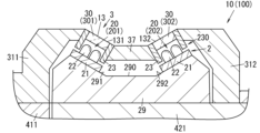
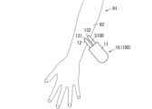
- FIG. 1 is a cross-sectional view of the photocosmetic device of Embodiment 1.
- FIG. 2 is a front view of the same photo-beauty device.
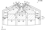
- FIG. 3 is a cross-sectional view of a main part of the same optical beauty device.
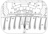
- FIG. 4 is a cross-sectional view showing a mode of use of the same photocosmetic device.
- FIG. 5 is a block diagram of the same photocosmetic device. 6 is a cross-sectional view of a main part of a photocosmetic device of Modification 1 of Embodiment 1.
- FIG. 7 is a cross-sectional view of a main part of a photocosmetic device of Modification 2 of Embodiment 1.
- FIG. 1 is a cross-sectional view of the photocosmetic device of Embodiment 1.
- FIG. 2 is a front view of the same photo-beauty device.
- FIG. 3 is a cross-sectional view of a main part of the same optical beauty device.
- FIG. 8 is a cross-sectional view of a main part of a photocosmetic device of Modification 3 of Embodiment 1.
- FIG. 9 is a cross-sectional view of a main part of a photocosmetic device of Modification 4 of Embodiment 1.
- FIG. 10 is a cross-sectional view of a main part of a photocosmetic device of Modification 5 of Embodiment 1.
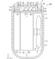
- FIG. 11 is a cross-sectional view of a photocosmetic device of Modification 6 of Embodiment 1.
- FIG. FIG. 12 is a cross-sectional view of a main part of a photocosmetic device of Modification 7 of Embodiment 1.
- FIG. 13 is a cross-sectional view of a main part of a photocosmetic device of Modification 8 of Embodiment 1.
- FIG. 14 is a cross-sectional view of a main part of a photocosmetic device of Modification 9 of Embodiment 1.
- FIG. 15 is a conceptual diagram showing how the photocosmetic device of Comparative Example 1 is used.
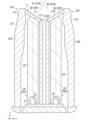
- 16 is a cross-sectional view of the photocosmetic device of Embodiment 2.
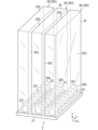
- FIG. 17 is a perspective view of a main part of the same photocosmetic device.
- FIG. 18 is a front view of the photocosmetics device same as the above.
- FIG. 19 is a cross-sectional view showing a mode of use of the same photocosmetic device.
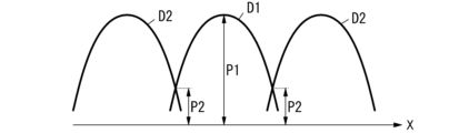
- FIG. 20 is a conceptual diagram showing the intensity distribution of light emitted from the above photocosmetic device.
- FIG. 21 is a conceptual diagram showing how to use the same photocosmetic device.
- 22 is a perspective view of a main part of a photocosmetic device of Modification 1 of Embodiment 2.
- FIG. 23 is a cross-sectional view of a main part of a photocosmetic device of Modification 2 of Embodiment 2.
- FIG. 24 is a cross-sectional view of a main part of a photocosmetic device of Modification 3 of Embodiment 2.
- FIG. FIG. 25 is a perspective view of a main part of the same photocosmetic device.
- FIG. 26 is a cross-sectional view of a main part of a photocosmetic device of Modification 4 of Embodiment 2.
- FIG. FIG. 27 is a cross-sectional view of a main part of another example of a photocosmetic device of Modification 4 of Embodiment 2.
- FIG. FIG. 28 is a cross-sectional view of a main part of a photocosmetic device of Modification 5 of Embodiment 2.
- FIG. 29 is a cross-sectional view of a main part of a photocosmetic device of Modification 6 of Embodiment 2.
- FIG. 30 is a cross-sectional view of a main part of Modification 7 of Embodiment 2.
- FIG. 31 is a cross-sectional view of a main part of a photocosmetic device of Modification 8 of Embodiment 2.
- FIG. FIG. 32 is a conceptual diagram showing how to use the same photocosmetic device.
- FIG. 33 is a cross-sectional view of a photocosmetic device of Comparative Example 2.
- FIG. FIG. 34 is a conceptual diagram showing how to use the same photocosmetic device.
- 35 is a perspective view of the photocosmetic device of Embodiment 3.
- FIG. 36 is a front view of the photocosmetics device same as the above.
- FIG. 37 is a cross-sectional view of the same optical cosmetic device.
- FIG. 38 is a conceptual diagram showing a mode of use of the same photocosmetic device.
- 39 is a cross-sectional view of a main part of a photocosmetic device of Modification 1 of Embodiment 3.
- FIG. 40 is a cross-sectional view of a main part of a photocosmetic device of Modification 2 of Embodiment 3.
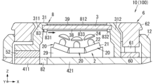
- FIG. 41 is a cross-sectional view of a photocosmetic device of Embodiment 4.
- FIG. FIG. 42 is a cross-sectional view showing a mode of use of the same photocosmetic device.
- 43 is a cross-sectional view of a main part of a photocosmetic device of Modification 1 of Embodiment 4.
- FIG. 44 is a cross-sectional view of a main part of a photocosmetic device of Modification 2 of Embodiment 4.
- FIG. 45 is a cross-sectional view of a main part of a photocosmetic device of Modification 3 of Embodiment 4.
- FIG. FIG. 46 is a block diagram of a photocosmetic device of Modification 4 of Embodiment 4.
- FIG. 47 is a cross-sectional view of a main part of a photocosmetic device of Modification 5 of Embodiment 4.
- FIG. 48 is a cross-sectional view of a main part of a photocosmetic device of Modification 6 of Embodiment 4.
- FIG. 49 is a conceptual diagram for explaining the mechanism by which hair is expelled from the skin by light irradiation.
- FIG. 50 is a conceptual diagram for explaining the mechanism by which hair is expelled from the skin by light irradiation.
- FIG. 51 is a conceptual diagram for explaining the mechanism by which hair is expelled from the skin by light irradiation.
- Embodiment 1 (1.1) Overview of Embodiment 1
- the photocosmetic device 100 (see FIGS. 1 and 2) of the present embodiment irradiates the skin 92 (see FIG. 4) with light to cause the skin 92 to absorb the light.
- the photocosmetic device 100 of the present embodiment irradiates a region of the skin 92 where the hair 91 grows to promote the discharge of the hair 91 from the skin 92, thereby suppressing or depilating the hair.
- a hair treatment device is a hair treatment device.
- hair suppression is a concept that means temporarily removing hair 91 from a predetermined area of skin 92 .
- hairs 91 may grow back from a predetermined region of the skin 92 after the hairs 91 have temporarily disappeared from that region.
- hair removal is a concept that means removing hairs 91 from a predetermined area of the skin 92 and then making the hairs 91 no longer grow from this area (permanent hair removal). That is, the photocosmetic device 100 (body hair treatment device) of the present embodiment is a device for irradiating the skin 92 with light to suppress or remove hair.
- the following mechanisms are known for hair suppression or hair loss by light irradiation. That is, as shown in FIG. 49, when a region where hair 91 grows on the surface of skin 92 is irradiated with light L10, melanin in hair follicles 911 absorbs the irradiated light L10. The hair follicle portion 911 generates heat due to the energy of the absorbed light L10, and the hair matrix 912 is damaged by this heat. The hairs 91 whose hair matrix 912 has been damaged are then separated from the hair matrix 912 by biological action (see FIG. 50) and are expelled from the skin 92 (see FIG. 51).
- the optical cosmetic device 100 of this embodiment as shown in FIG. It is formed in a concave shape. Therefore, when the skin 92 is pressed against the light emitting surface 13 of the photocosmetic device 100, the surface of the skin 92 is deformed along the light emitting surface 13 as shown in FIG. state of being drawn into the space surrounded by the emission surface 13). Along with this, the portion of the skin 92 where the hair matrix 912 of the hair 91 exists also approaches the light emitting surface 13 .
- the light L1 from the plurality of light source units 20 is emitted from the concave light emission surface 13 into the space surrounded by the light emission surface 13. released towards. Therefore, the light L1 from the multiple light source units 20 crosses inside the skin 92 drawn into the space surrounded by the light emitting surface 13 . This increases the possibility that the light L1 emitted from the plurality of light source units 20 intersects within the skin 92 at a desired region (for example, near the periphery of the hair matrix 912). As a result, for example, the light L1 can be absorbed near the periphery of the hair matrix 912 in the skin 92 to efficiently damage the hair matrix 912 .
- a plurality of light source units 20 are arranged so that the light L1 from the light source units 20 intersects at the position of (hair bulb).
- the light L1 from the plurality of light source units 20 can be condensed at the position of the hair matrix 912 within the skin 92 . This makes it possible to efficiently absorb the light L1 in the vicinity of the periphery of the hair matrix 912 in the skin 92 and efficiently damage the hair matrix 912 .
- the total energy of the light L1 from the plurality of light source units 20 at the position of the hair matrix 912 is such that the hair 91 is discharged. It is sufficient if it has a size that can damage the hair matrix 912 . Therefore, as the light source 22 of each light source unit 20, it is possible to use a light source with a relatively low intensity of the light L1, and it is possible to reduce the amount of the light L1 absorbed by substances such as moisture in the skin 92. Become. As a result, it is possible to reduce the magnitude of heat generated in the skin 92 at a position other than the portion where the light L1 intersects (for example, near the surface layer of the skin 92), thereby reducing discomfort given to the user. becomes possible.
- the optical beauty device 100 of this embodiment is a body hair treatment device for treating body hair (hair 91 ) grown on the skin 92 .
- X-axis first axis
- Y axis second axis
- Z axis third axis
- the X-axis, Y-axis, and Z-axis are all virtual axes, and the arrows indicating "X", "Y", and "Z” in the drawings are merely used for explanation. , none of which is material.
- the positive direction of the X-axis is also referred to as “right”, the negative direction of the X-axis is referred to as “left”, the positive direction of the Z-axis is referred to as “forward”, and the negative direction of the Z-axis is referred to as “rear”. .
- these directions are not meant to limit the directions during use of the optical cosmetic device 100 .
- hair (body hair) as used in the present disclosure includes various hairs 91 protruding from the skin 92, that is, various hairs extending from the skin 92, such as human (human) hair, beard, eyebrows, and shin hair. , nose or ear hair.
- various hairs 91 protruding from the skin 92 of mammals such as dogs and cats and other animals are also included in the term “hair (body hair)” in the present disclosure.
- the body hair treatment device as an example of the photocosmetic device 100 of the present embodiment is a device for irradiating the skin 92 from which these hairs 91 protrude.
- the "user" in the present disclosure means a subject having skin 92 irradiated with light L1 from the optical beauty device 100, such as a person, mammals, other animals, and the like. If the user is a person, the optical beauty device 100 may be operated (and held) by the user himself/herself, or may be operated and used by a person other than the user. If the user is an animal other than a human, the optical beauty device 100 is basically operated and used by a person other than the user.
- the "operator" in the present disclosure means a person who operates the optical beauty device 100.
- the operator may be the user himself or may be someone other than the user.
- two members are thermally connected means that two members are in contact with each other, and one or more other members (hereinafter also referred to as “heat transfer members”). ) is a concept that includes both the case of being connected via Note that the heat transfer coefficient of the heat transfer member here is higher than that of air.
- the hair suppressing device 10 as an example of the optical beauty device 100 (body hair treatment device) according to the present embodiment will be described below.
- the hair suppressing device 10 includes a housing 1, a light emitting surface 13, a light emitting portion 2, a transmitting member 3, a heat radiating portion 4, a cooler 5, an operating portion 6, and a control portion. 71 (see FIG. 5) and a power supply section 72 (see FIG. 5).
- the housing 1 has a first case 11 and a second case 12.
- the first case 11 is made of resin, for example.
- the first case 11 has a tubular shape that opens forward. Left and right side walls of the first case 11 are formed with a plurality of ventilation holes 111 passing through the side walls along the X-axis.
- the first case 11 is, for example, a portion held by an operator when using the hair suppressing device 10 .
- the second case 12 is made of resin, for example.
- the second case 12 has a peripheral wall shape protruding forward from the peripheral edge of the front opening of the first case 11 .
- the second case 12 is coupled to the first case 11 by coupling members such as screws.
- the housing 1 accommodates the light emitting section 2, the transmitting member 3, the heat radiating section 4, the cooler 5, the control section 71, and the power supply section 72 inside.
- the operating portion 6 is held by the housing 1 .
- the radiator 4 and cooler 5 are housed in a first case 11 .
- the light emitting section 2 and the transmissive member 3 are housed in the second case 12 .
- the control unit 71 and the power supply unit 72 are housed in the first case 11 .
- the operation part 6 is held by the second case 12 with a part thereof exposed.
- the light emitting surface 13 is a surface that emits the light from the light emitting section 2 to the outside of the housing 1 .
- the light emitting surface 13 is positioned on the front surface of the housing 1 (the front surface of the second case 12).
- the light emitting surface 13 has a concave shape that is recessed inward of the housing 1 .
- the light emitting surface 13 includes a planar bottom surface 130 orthogonal to the Z axis and a first inclined surface 131 located to the left of the bottom surface 130 and inclined diagonally forward left. and a second inclined surface 132 located on the right side of the bottom surface 130 and inclined diagonally forward right.
- the light emitting section 2 includes a plurality of (three in this case) light source units 20 and a holder 29 .
- each of the plurality of light source units 20 includes a substrate 21, a light source 22, and a light shielding structure 23.
- the substrate 21 has a rectangular plate shape.
- the substrate 21 extends along the Y-axis.
- the light source 22 is mounted on the substrate 21.
- the light source 22 is mounted on the front surface of the substrate 21 .
- the light source 22 includes multiple LEDs (Light Emitting Diodes) 221 .
- the LED 221 is a so-called bullet-shaped LED, and an LED element (semiconductor element) is enclosed in a bullet-shaped resin case.
- the emission wavelength of the LED 221 is within the range of 600 nm to 1000 nm.
- the LEDs 221 are red LEDs or near-infrared LEDs.
- An example of the emission wavelength of the LED 221 is approximately 850 nm.
- Another example of the emission wavelength of the LED 221 is about 950 nm.
- the emission wavelength of the LED 221 means the peak emission wavelength of the LED 221, that is, the wavelength at which the intensity is maximized in the emission spectrum of the LED 221.
- the LED 221 is a monochromatic light source that emits monochromatic light. LED 221 emits light with a relatively narrow spectral width.
- the width of the emission spectrum of the LED 221 is, for example, approximately 60 nm to 100 nm. In the present disclosure, “width of emission spectrum of LED 221 ” means full width at half maximum of emission spectrum of LED 221 .
- the multiple LEDs 221 have the same emission wavelength.
- “the emission wavelengths of the plurality of LEDs 221 are the same” is not limited to the case where the emission wavelengths (peak emission wavelengths) of the plurality of LEDs 221 completely match, and errors that may occur during manufacturing, for example, are allowed.
- the multiple LEDs 221 are arranged in an array on the substrate 21 . That is, the light source 22 has an LED array in which a plurality of LEDs 221 are arranged in an array.
- the light source 22 has 16 LEDs 221 .
- the 16 LEDs 221 are arranged in a 2 ⁇ 8 array with two along the X-axis and eight along the Y-axis when viewed from the front.
- Each of the plurality of LEDs 221 is mounted on the substrate 21 so as to have a light distribution characteristic with an intensity peak in the normal direction of the substrate 21 . That is, the optical axis of each of the plurality of LEDs 221 is along the normal direction of the substrate 21 on which the LEDs 221 are mounted.
- the optical axis of the light source 22 is along the normal direction of the substrate 21 .
- the optical axis of the light source 22 including the plurality of LEDs 221 means a virtual axis (columnar axis) defined by a region surrounded by the optical axes of the plurality of LEDs 221.
- the projection area obtained by projecting the optical axis of the light source 22 onto a virtual plane perpendicular to the normal direction of the substrate 21 is an area surrounded by the optical axes of the plurality of LEDs 221 on the substrate 21. It has the same size (area) and shape as (rectangular area).
- each of the plurality of light source units 20 has an optical axis A10 (see FIG. 3).
- the optical axis A10 of the light source unit 20 is an imaginary line that represents the luminous flux emitted from the light source unit 20 .
- the optical axis A ⁇ b>10 of the light source unit 20 coincides with the optical axis of the light source 22 .
- An optical axis A10 of the light source unit 20 extends along the normal direction of the substrate 21 .
- the light shielding structure 23 has a shape surrounding the light source 22 when viewed from the normal direction of the substrate 21 .
- the light shielding structure 23 surrounds the light source 22 without gaps when viewed from the normal direction of the substrate 21 .
- the light shielding structure 23 has a rectangular frame shape when viewed from the normal direction of the substrate 21 .
- the light shielding structure 23 has a wall shape extending along the normal direction of the substrate 21 . That is, the light shielding structure 23 is a rectangular frame-shaped wall surrounding the light source 22 (plurality of LEDs 221 ) when viewed from the normal direction of the substrate 21 .
- the light shielding structure 23 reduces the amount of light (leakage light) directed to the outside of the substrate 21 (the outside of the substrate 21 on a virtual plane perpendicular to the normal direction of the substrate 21) among the light emitted from the light source 22. do.
- the light shielding structure 23 prevents the light emitted from the light source 22 of the light source unit 20 to which the light shielding structure 23 belongs from leaking to the other light source units 20 .
- the light shielding structure 23 is open on the side (front side) where the light from the light source 22 is emitted. Light from the light source 22 is emitted in the normal direction (forward) of the substrate 21 through this opening.
- the light shielding structure 23 has thermal conductivity.
- the light shielding structure 23 is made of metal, for example.
- a mirror that reflects the light from the light source 22 is formed on the inner surface of the light shielding structure 23 . Accordingly, the light emitted from the light source 22 and reaching the light shielding structure 23 can be reflected forward by the mirror, and the amount of light L1 emitted from the light source unit 20 can be increased.
- the front edges of the light shielding structures 23 of the plurality (three) of the light source units 20 are connected and integrated.
- the (three) light shielding structures 23 of the plurality (three) light source units 20 constitute the light shielding section 230 . That is, in the hair suppressing device 10 of this embodiment, the light shielding part 230 has the three integrated light shielding structures 23 .
- the light shielding part 230 blocks light (leakage light) from the light source 22 of one light source unit 20 out of the plurality of light source units 20 toward the light source 22 of at least one light source unit 20 out of the remaining plurality of light source units 20 . configured to reduce
- the holder 29 has thermal conductivity.
- the holder 29 can be made of metal or ceramic, for example.
- the holder 29 holds the substrates 21 of the plurality (three) of the light source units 20 .
- the holder 29 holds the substrates 21 of the plurality of light source units 20 such that the plurality (three) of the light source units 20 are arranged along the X-axis.
- a plurality (three) of light source units 20 are arranged side by side along the X-axis such that the short axes of the respective substrates 21 match when viewed from the front.
- the three light source units 20 may be referred to as a first light source unit 201, a second light source unit 202, and a third light source unit 203, respectively.
- the first light source unit 201 is the leftmost (negative side of the X-axis) light source unit 20 among the three light source units 20 .
- the second light source unit 202 is the rightmost (positive side of the X-axis) light source unit 20 among the three light source units 20 .
- the third light source unit 203 is the central light source unit 20 among the three light source units 20 .
- the first light source unit 201 to the third light source unit 203 are arranged in the order of the first light source unit 201, the third light source unit 203, and the second light source unit 202 along the X-axis.
- the front surface of the holding body 29 has a concave shape in which the central portion on the X axis is recessed rearward (negative side of the Z axis).
- the front surface of the holding member 29 includes a planar bottom surface 290 orthogonal to the Z axis, a first inclined surface 291 that inclines diagonally forward left from the left edge of the bottom surface 290, and a first inclined surface 291 that inclines diagonally forward right from the right edge of the bottom surface 290. and a second inclined surface 292 .
- the bottom surface 290 of the front surface of the holder 29 is parallel to the bottom surface 130 of the light emitting surface 13 .
- a first inclined surface 291 on the front surface of the holder 29 is parallel to the first inclined surface 131 of the light emitting surface 13
- a second inclined surface 292 on the front surface of the holding member 29 is parallel to the second inclined surface 131 of the light emitting surface 13 . It is parallel to the inclined surface 132 .
- the substrate 21 of the first light source unit 201 is arranged on the first inclined surface 291
- the substrate 21 of the second light source unit 202 is arranged on the second inclined surface 292
- the substrate 21 of the third light source unit 203 is arranged on the bottom surface 290 . ing.
- the optical axis A1 (A10) of the first light source unit 201 is non-parallel to the optical axis A2 (A10) of the second light source unit 202.
- the optical axis A ⁇ b>1 of the first light source unit 201 intersects the optical axis A ⁇ b>2 of the second light source unit 202 outside the housing 1 .
- the optical axis A1 of the first light source unit 201 is non-parallel to the optical axis A3 (A10) of the third light source unit 203.
- the optical axis A ⁇ b>1 of the first light source unit 201 crosses the optical axis A ⁇ b>3 of the third light source unit 203 outside the housing 1 .
- the optical axis A2 of the second light source unit 202 is non-parallel to the optical axis A3 of the third light source unit 203.
- the optical axis A2 of the second light source unit 202 intersects the optical axis A3 of the third light source unit 203 outside the housing 1 .
- the optical axes A10 of the plurality (three) of the light source units 20 are non-parallel to each other.
- the optical axes A10 of the plurality (three) of light source units 20 intersect at one point. As shown in FIG. 3 , the optical axes A10 of the plurality (three) of light source units 20 intersect outside the housing 1 in front of the light emitting surface 13 .
- the plurality (three) of light source units 20 are in a state in which the surface of the skin 92 is in contact with the light emitting surface 13 (the skin 92 is pulled into the space surrounded by the light emitting surface 13). state), the light L1 from the plurality of light source units 20 is arranged so as to intersect near the hair matrix 912 (hair bulb) in the skin 92 .
- the light L1 from the plurality of light source units 20 is 2 mm to 5 mm from the bottom surface 130 in the skin 92 while the surface of the skin 92 is in contact with the light emitting surface 13 of the plurality (three) of the light source units 20. They are arranged so as to intersect at a position within a certain range (for example, about 4 mm).
- intersection angle between the plurality (three) of light source units 20 is the light L1 intersect near the hair matrix 912 in the skin 92, the refractive index of the skin 92 and the like are also considered.
- the crossing angle between the two light source units 20 having the largest crossing angle is, for example, in the range of 10° or more and less than 180°.
- intersection angle ⁇ 1 is the value of When the intersection angle ⁇ 1 is less than 10°, when the two light source units 20 are arranged so that the light L1 intersects at a depth within the range of about 2 mm to 5 mm (for example, about 4 mm) from the surface of the skin 92, the light source 22 Fewer LEDs 221 may be included and the amount of light from the light source 22 may be reduced. Moreover, when the crossing angle ⁇ 1 is 180° or more, it becomes difficult to deform the skin 92 along the concave light emitting surface 13 . Further, when the crossing angle ⁇ 1 is increased, the light source unit 20 needs to be placed far away in order to cross the optical axis A10 inside the skin 92, which leads to an increase in the size of the device.
- the intersection angle ⁇ 1 may be less than 170°.
- the crossing angle ⁇ 1 may be a value in the range of 50° or more and 160° or less, or may be a value in the range of 90° or more and 150° or less.
- the intensity of the light emitted from the light emitting section 2 is such that the intensity of the irradiated light on the light emitting surface 13 is within the range of 15 W/cm 2 to 35 W/cm 2 .
- the light emitted from the light emitting section 2 is light whose emission time is in the range of 500 ms to 2000 ms, for example.
- the substrates 21 of the plurality of light source units 20 are separated from each other without being in contact with each other along the axis (X-axis) along which the plurality of light source units 20 are arranged.
- the distance between substrates 21 in two adjacent light source units 20 is larger than the size of one LED 221, for example.
- the light sources 22 of the plurality of light source units 20 are separated from each other without being in contact with each other along the axis (X-axis) along which the plurality of light source units 20 are arranged.
- the distance between the light sources 22 (the LEDs 221) in two adjacent light source units 20 is larger than the size of one LED 221, for example.
- the light sources 22 of the plurality of light source units 20 are arranged apart from each other. Since the plurality of light sources 22 are spaced apart from each other in this manner, overlapping of the light L1 emitted from the plurality of light source units 20 on the light emitting surface 13 is reduced.
- the light sources 22 of the plurality of light source units 20 are mutually arranged so that the light L1 emitted from two adjacent light source units 20 does not substantially overlap on the light emitting surface 13. placed apart.
- the light L1 emitted from the two light source units 20 does not substantially overlap on the light emitting surface 13 means, for example, that one of the two light source units 20 is It means that the light L1 from the other light source unit 20 does not substantially hit the transmissive piece 30 (described later) arranged corresponding to the other light source unit 20 .
- the hair suppressing device 10 of the present embodiment includes the light shielding portion 230 (light shielding structure 23), which further reduces the overlap of the light L1 emitted from the plurality of light source units 20 on the light emitting surface 13. be done.
- the transparent member 3 is arranged in front of the light emitting section 2 .
- the surface of the transmissive member 3 constitutes at least part of the light emitting surface 13 .
- the outer surface (front surface) of the housing 1 in the transmissive member 3 constitutes (the entirety of) the light emitting surface 13 .
- the transmissive member 3 transmits light from the light sources 22 of the plurality of light source units 20 of the light emitting section 2 . 2, illustration of the transmissive member 3 is omitted.
- the transmissive member 3 is made of a material having a low absorptance for the wavelength of light emitted from the light source 22 . That is, the transmissive member 3 is made of a material with low absorption loss for light emitted from the light source 22 .
- the transmissive member 3 is transparent at the wavelength of light emitted from the light source 22 .
- the transmissive member 3 is made of a material with a small extinction coefficient at the wavelength of light emitted from the light source 22 .
- the transmissive member 3 is preferably made of a material having an extinction coefficient of 0.0 at the wavelength of light emitted from the light source 22 .
- the transmissive member 3 When the light absorptivity of the transmissive member 3 is small, the transmissive member 3 is less likely to absorb light, and the temperature rise of the transmissive member 3 is suppressed. This makes it possible to suppress irritation to the skin 92 in contact with the transmissive member 3 .
- the transparent member 3 is made of a material having a higher refractive index than the human skin 92 at the wavelength of the light emitted from the light source 22 (the emission wavelength of the light source 22).
- the transmissive member 3 is made of a material having a refractive index of 1.7 or more at the emission wavelength of the light source 22 .
- the refractive index is, for example, a value measured according to the method for measuring the refractive index of optical glass specified in JIS B 7071.
- the transmissive member 3 has thermal conductivity.
- the transmissive member 3 is made of a material having a thermal conductivity of 1 W/mK or more.
- the thermal conductivity is, for example, a value measured according to the method of measuring thermal conductivity by the flash method for fine ceramics specified in JIS R 1611. If the transmissive member 3 has thermal conductivity, it is possible to promote cooling of objects in contact with the transmissive member 3 .
- the transmissive member 3 is made of, for example, a material having a refractive index of 1.7 or more at the wavelength of the light L1 emitted from the light source 22 and a thermal conductivity of 1 W/mK or more.
- the transparent member 3 is made of sapphire (Al 2 O 3 ), zinc oxide (ZnO), zirconium oxide (ZrO 2 ), magnesium oxide (MgO), gallium nitride (GaN), aluminum nitride (AlN), diamond made of at least one material selected from the group consisting of
- the transparent member 3 is preferably made of sapphire.
- the transparent member 3 may be made of two or more materials. Table 1 below shows the refractive index and thermal conductivity (W/mK) of these materials.
- the refractive indices shown in Table 1 are values at a specific wavelength (d-line: 587.6 nm). Further, since there is wavelength dispersion of the refractive index, the refractive index value of each material changes depending on the selected wavelength of the light source 22 . For example, in the case of sapphire, the value of the refractive index decreases with increasing wavelength, eg, the refractive index at a wavelength of 850 nm is 1.76. In the case of sapphire, the refractive index value increases as the wavelength becomes shorter. For example, the refractive index at a wavelength of 405 nm is 1.786.
- the transparent member 3 includes a plurality (three) of transparent pieces 30.
- Each of the plurality of transmission pieces 30 has a plate shape.
- the multiple transmission pieces 30 correspond to the multiple light source units 20 (one-to-one).
- each of the plurality of transmissive pieces 30 is arranged on the optical axis A10 of the corresponding light source unit 20.
- Each of the multiple transmissive pieces 30 faces the light source 22 of the corresponding light source unit 20 .
- Each transmission piece 30 is fixed to the light shielding structure 23 of the corresponding light source unit 20 so as to close the front opening of the light shielding structure 23 of the corresponding light source unit 20 .
- the transmission piece 30 corresponding to the first light source unit 201 is also referred to as the first transmission piece 301
- the transmission piece 30 corresponding to the second light source unit 202 is referred to as the second transmission piece.
- the transmission piece 30 corresponding to the third light source unit 203 is also called a third transmission piece 303 .
- the front surface of the first transmitting piece 301 corresponds to the first inclined surface 131 of the light emitting surface 13 .
- the front surface of the second transmission piece 302 corresponds to the second inclined surface 132 of the light emitting surface 13 .
- the front surface of the third transmissive piece 303 corresponds to the bottom surface 130 of the light emitting surface 13 . That is, the light emitting surface 13 is composed of the front surface of the first transmission piece 301 (first inclined surface 131), the front surface of the second transmission piece 302 (second inclined surface 132), and the front surface of the third transmission piece 303 (bottom surface 130). including.
- the depth X1 of the concave space surrounded by the light emitting surface 13 is a value greater than 0 mm and 30 mm or less.
- the depth X1 of the concave space surrounded by the light emitting surface 13 means the depth of the surface from which the light can actually be emitted from the housing 1. As shown in FIG. In one specific example, "the depth X1 of the concave space surrounded by the light emitting surface 13" is the end of the first inclined surface 131 away from the bottom surface 130 (or the second inclined surface 132 from the bottom surface 130). the far end) and the bottom surface of the concave space (bottom surface 130) along the Z axis (see FIG. 3).
- the depth X1 preferably has a value of 2 mm or more and 30 mm or less.
- the depth X1 By setting the depth X1 to be equal to or greater than the lower limit of the above range, it is possible to emit a plurality of non-parallel lights from the light emitting surface 13, and the plurality of non-parallel lights can be crossed in the vicinity of the hair matrix 912. , it is possible to increase the amount of light condensed near the hair matrix 912 . If the depth X1 is larger than the upper limit of the above range, it becomes difficult to deform the skin 92 along the light emitting surface 13 .
- each transmissive piece 30 intersects the optical axis A10 of the corresponding light source unit 20.
- the front surface of each transmissive piece 30 is perpendicular to the optical axis A10 of the corresponding light source unit 20 .
- the front surface (first inclined surface 131 ) of the first transmission piece 301 intersects (here, orthogonally) the optical axis A1 of the first light source unit 201 .
- the front surface (second inclined surface 132 ) of the second transmitting piece 302 intersects (here, orthogonally) the optical axis A ⁇ b>2 of the second light source unit 202 .
- the front surface (bottom surface 130 ) of the third transmission piece 303 intersects (here, orthogonally) the optical axis A3 of the third light source unit 203 .
- the optical axis A10 of each of the light sources 22 of the plurality of light source units 20 intersects (here, orthogonally) the light emitting surface 13 . This makes it possible to improve the efficiency of light extraction from the light emitting surface 13 .
- the hair suppressing device 10 of the present embodiment includes the partitioning portion 32 (the front edge portion of the light shielding structure 23) that partitions the plurality of transmissive pieces 30 on the light emitting surface 13. As shown in FIG. Due to the presence of the partition section 32 , overlapping of the light L ⁇ b>1 emitted from the plurality of light source units 20 on the light emitting surface 13 is reduced.
- the transmissive piece 30 is fixed to the light shielding structure 23. Therefore, by positioning the plurality of light shielding structures 23 with respect to the plurality of light sources 22 , the plurality of transmissive pieces 30 are positioned with respect to the plurality of light sources 22 .
- the transparent member 3 is held by the holding portion 31 .
- the holding part 31 is part of the housing 1 .
- the holding portion 31 indirectly holds the light shielding portion 230 (the plurality of light shielding structures 23 integrated), thereby indirectly keeping.
- the holding portion 31 has thermal conductivity.
- the holding portion 31 is made of metal, for example. Since the holding portion 31 that holds the transparent member 3 has thermal conductivity, it is possible to further promote cooling of the object in contact with the transparent member 3 .
- the holding portion 31 has a first holding arm 311 and a second holding arm 312.
- the first holding arm 311 is coupled to the left edge of the light shielding portion 230 (the left edge of the light shielding structure 23 of the first light source unit 201), and the second holding arm 312 is coupled to the light shielding portion.
- the light shielding part 230 is held by the holding part 31 by being coupled to the right edge of the light shielding structure 230 (the right edge of the light shielding structure 23 of the second light source unit 202 ).
- the transmission member 3 (the plurality of transmission pieces 30) is thermally connected to the holding section 31 via the light shielding section 230. As a result, heat from an object in contact with the transmissive member 3 can be transmitted to the holding section 31 via the light shielding section 230 (light shielding structure 23).
- the heat radiating section 4 includes a first heat radiating section 41 and a second heat radiating section 42 .
- the first heat radiation part 41 mainly radiates the heat of the transmissive member 3 .
- the second heat dissipation part 42 mainly dissipates the heat of the transmissive member 3 and the light emitting part 2 .
- the first heat radiation part 41 includes a first connecting part 411 and a first heat radiation member 412 .
- the first connecting portion 411 has thermal conductivity.
- the first connecting portion 411 is made of metal, for example.
- the first connecting part 411 has a plate shape that has a thickness along the Z axis and extends along the Y axis.
- the first connecting portion 411 is arranged inside the housing 1 so as to close the left side portion of the front opening of the first case 11 .
- a first holding arm 311 of the holding portion 31 is provided on the front surface of the first connecting portion 411 .
- the first heat radiation member 412 has thermal conductivity.
- the first heat dissipation member 412 is made of metal, for example.
- the first heat radiation member 412 has a plurality of first heat radiation fins.
- Each of the plurality of first heat radiating fins has a plate shape that protrudes rearward from the rear surface of the first connecting portion 411 .
- the plurality of first heat radiating fins are connected by a first connecting portion 411 .
- the plurality of first heat radiation fins are arranged in the internal space of the first case 11 .
- the plurality of first heat radiation fins are arranged along the Y-axis. There is a gap between two first heat radiation fins adjacent to each other in the Y axis.
- the first heat radiation member 412 is thermally connected to the transmissive member 3 via the first connecting portion 411 , the first holding arm 311 and the light blocking portion 230 . Therefore, the heat of the transmissive member 3 is transmitted to the plurality of first heat radiation fins of the first heat radiation member 412 via the light shielding portion 230, the first holding arm 311 and the first connecting portion 411, and the heat from the plurality of first heat radiation fins It is discharged to the outside (for example, via the ventilation hole 111 of the first case 11).
- the second heat radiation part 42 includes a second connecting part 421 and a second heat radiation member 422 .
- the second connecting portion 421 has thermal conductivity.
- the second connecting portion 421 is made of metal, for example.
- the second connecting part 421 has a plate shape with a thickness along the Z axis.
- the second connecting part 421 is arranged inside the housing 1 so as to close the central part and the right part of the front opening of the first case 11 .
- the holding body 29 of the light emitting part 2 and the second holding arm 312 of the holding part 31 are provided on the front surface of the second connecting part 421 .
- the second heat radiation member 422 has thermal conductivity.
- the second heat dissipation member 422 is made of metal, for example.
- the second heat radiation member 422 has a plurality of second heat radiation fins.
- Each of the plurality of second heat radiating fins has a plate shape that protrudes rearward from the left portion of the rear surface of the second connecting portion 421 .
- the plurality of second heat radiating fins are connected by the second connecting portion 421 .
- a plurality of second heat radiation fins are arranged in the internal space of the first case 11 .
- the plurality of second heat radiation fins are arranged along the Y-axis. There is a gap between two second heat radiating fins adjacent to each other on the Y axis.
- the first heat radiation fin and the second heat radiation fin are at the same position on the Y axis. Therefore, the gap between the first heat radiating fins and the gap between the second heat radiating fins are at the same position on the Y axis.
- the second heat dissipation member 422 is thermally connected to the substrates 21 of the plurality of light source units 20 via the second connecting portion 421 and the holder 29 . Therefore, the heat generated by the light source 22 of the light source unit 20 is transmitted to the plurality of second heat radiating fins of the second heat radiating member 422 via the holder 29 and the second connecting portion 421, and from the plurality of second heat radiating fins ( For example, it is discharged to the outside through the ventilation hole 111 of the first case 11 .
- the second heat radiation member 422 is thermally connected to the transmissive member 3 via the second connecting portion 421 , the second holding arm 312 and the light shielding portion 230 . Therefore, the heat of the transmissive member 3 is transmitted to the plurality of second heat radiating fins of the second heat radiating member 422 via the light shielding portion 230, the second holding arm 312 and the second connecting portion 421, and the heat from the plurality of second heat radiating fins is transmitted. It is discharged to the outside (for example, through a through hole of the first case 11).
- the heat of the transmissive member 3 is discharged to the outside through the first heat radiation member 412 and the second heat radiation member 422 . Therefore, an object in contact with the transmissive member 3 is cooled by being deprived of heat by the transmissive member 3 . That is, the transmissive member 3 has a cooling ability to cool an object in contact with the transmissive member 3 .
- the surface (front surface) of the transmissive member 3 constitutes the light emitting surface 13 .
- the hair suppressing device 10 is used with the skin 92 in contact with the front surface (light emitting surface 13) of the transmissive member 3 (see FIG. 4). Therefore, when the hair suppressing device 10 is in use, the skin 92 in contact with the front surface (light emitting surface 13) of the transmissive member 3 is deprived of heat by the transmissive member 3 and cooled. That is, the transparent member 3 has a cooling ability to cool the skin 92 in contact with the transparent member 3 . Since the permeable member 3 has a cooling ability, the temperature rise in the vicinity of the surface layer of the skin 92 is suppressed, the stimulation of the pain nerves of the skin 92 is reduced, and the discomfort given to the user can be reduced. becomes.
- the cooler 5 is arranged inside the first case 11 .
- the cooler 5 includes a cooling fan 51 .
- the cooling fan 51 is arranged side by side with the second heat radiating member 422 and the first heat radiating member 412 on the X axis in the first case 11 .
- the cooling fan 51 blows air leftward (negative direction of the X-axis).
- the wind sent out from the cooling fan 51 impinges on the second heat radiating member 422 and the first heat radiating member 412 and takes heat from the second heat radiating member 422 and the first heat radiating member 412 .
- This promotes cooling of the second heat radiating member 422 and the first heat radiating member 412 .
- the transmissive member 3 thermally connected to the first heat radiation member 412 and the second heat radiation member 422 is cooled.
- the cooler 5 cools the transmissive member 3 .
- the temperature rise in the vicinity of the surface layer of the skin 92 is further suppressed, and it is possible to further reduce the discomfort given to the user.
- the operation of the cooler 5 is controlled by the controller 71 so that, for example, the temperature of the surface of the skin 92 in contact with the transmissive member 3 is within a predetermined temperature range.
- the predetermined temperature range is, for example, -5°C to 35°C.
- the hair suppression device 10 may include a temperature sensor that measures the temperature of the skin 92, and the controller 71 may operate the cooler 5 based on the measurement result of the temperature sensor. Even if the hair suppressing device 10 is not equipped with a temperature sensor, the operating conditions of the cooler 5 (the rotation speed of the cooling fan 51, etc.) can be set appropriately in advance, and the operation input from the operator using a switch or the like can be performed. By enabling the operation of the cooler 5 to be turned on and off accordingly, the surface temperature of the skin 92 can be controlled within the predetermined temperature range.
- the operation unit 6 accepts operations from the operator. As shown in FIG. 1, the operation unit 6 includes a substrate 60 arranged on the front surface of the second connecting portion 421, a switch 61 mounted on the front surface of the substrate 60, and a switch 61 arranged in front of the switch 61. and a push button 62 that moves backward in response to the operation of , and pushes the switch 61 .
- the push button 62 is formed like a peripheral wall so as to surround the plurality of light source units 20 of the light emitting section 2 .
- the push button 62 As shown in FIG. 1, on the front surface of the push button 62, at a position corresponding to the light emitting surface 13 on the X axis, there is a recess that is recessed rearward (negative side of the Z axis) along the concave shape of the light emitting surface 13. place is formed.
- the push button 62 is held by the housing 1 so that the front surface of the push button 62 protrudes forward from the front surface of the housing 1 (the front surface of the second case 12), as shown in FIG. Therefore, when the hair suppressing device 10 is pressed against the skin 92, the part of the skin 92 around the part that contacts the transparent member 3 contacts the front surface of the push button 62 and pushes the push button 62 backward. As a result, the switch 61 is pushed by the push button 62 . In this way, by configuring the push button 62 to be pushed by the skin 92 when the skin 92 comes into contact with the transmissive member 3, it is possible to suppress the occurrence of a situation in which light is accidentally emitted from the light emitting section 2. It becomes possible.
- the control unit 71 controls the operation of the hair suppressing device 10 .
- the control unit 71 controls operations of the light emitting unit 2 and the cooler 5 .
- the control unit 71 includes, for example, a microcontroller having one or more processors and one or more memories.
- the microcontroller realizes the function as the control unit 71 by executing programs recorded in one or more memories with one or more processors.
- the program may be recorded in memory in advance, recorded in a non-temporary recording medium such as a memory card and provided, or provided through an electric communication line.
- the program is a program for causing one or more processors to function as the control unit 71 .
- the control unit 71 controls the operations of the light emitting unit 2 and the cooler 5 according to the operation of the operation unit 6, for example. For example, when the switch 61 is pushed in response to the pushing operation of the push button 62 , the control section 71 causes the light emitting section 2 to start emitting light and causes the cooling fan 51 to start operating. For example, when the push operation of the switch 61 by the push button 62 is released, the control unit 71 stops the emission of light from the light emitting unit 2, and the cooling fan 51 operates after a predetermined time (0 seconds may be acceptable). to stop
- the power supply unit 72 supplies power to the light emitting unit 2, the cooler 5 and the control unit 71.
- the power supply unit 72 supplies DC power to the light emitting unit 2 , the cooler 5 and the control unit 71 .
- the power supply unit 72 is, for example, a battery.
- the power supply unit 72 includes, for example, a rechargeable secondary battery and a charging circuit that converts AC power from an external AC power supply into DC power to charge the secondary battery.
- the power supply unit 72 is not limited to this, and may be a power supply circuit including an AC/DC converter that converts AC power from an external AC power supply into DC power.
- the optical cosmetic device 200 of Comparative Example 1 includes a plurality of light sources 22, as shown in FIG. Further, in the optical cosmetic device 200 of Comparative Example 1, the light emitting surface 13 is planar. In the optical cosmetic device 200 of Comparative Example 1, the light L100 from the plurality of light sources 22 is planarly emitted from the light emitting surface 13 .
- the hair 910 is irradiated with light. Assume that the mother 912 is damaged.
- the light emitted from the light source 22 positioned in front of the hair 910 among the plurality of light sources 22 reaches the hair matrix 912 of the hair 910 .
- the skin 92 is advanced a distance C11.
- the distance C11 is a distance corresponding to the depth (approximately 2 mm to 5 mm) at which the hair matrix 912 of the hair 91 is positioned within the skin 92 .
- the light emitted from the light source 22 positioned away from the hair 910 in the horizontal direction passes through the skin 92 before reaching the hair matrix 912 of the hair 910. It is necessary to travel a distance C12 (C12>C11), which is greater than the distance C11.
- C12 C12>C11
- the intensity of the light is attenuated by being absorbed by substances such as moisture present within skin 92 as the light travels through skin 92 . Therefore, light emitted from a light source 22 located away from the hair 910 may cause less damage to the hair matrix 912 of the hair 910 .
- the light absorbed by substances such as moisture in the skin 92 is converted into heat and stimulates pain nerves and the like in the skin 92, which can make the user feel uncomfortable.
- the skin 92 is irradiated with the light L1. That is, in the photocosmetic device 100 of the present embodiment, the skin 92 is irradiated with the light L1 while the hair matrix 912 of the hair 910 is close to the bottom surface 130 of the light emitting surface 13 .
- the distance C1 that the light L1 emitted from the light source unit 20 (third light source unit 203) positioned in front of the hair 910 travels through the skin 92 until it reaches the hair matrix 912 of the hair 910 is the distance C1 within the skin 92. This distance corresponds to the depth of the hair matrix 912 (approximately 2 mm to 5 mm).
- the light L1 emitted from the light source units 20 (the first light source unit 201 and the second light source unit 202) positioned away from the hair 910 in the left-right direction
- the distance C2 traveled in the skin 92 until reaching the hair matrix 912 is approximately the same as the distance C1 (C2 ⁇ C1). That is, in the optical cosmetic device 100 of the present embodiment, not only the light L1 emitted from the light source unit 20 located in front of the hair 910 but also the light L1 emitted from the light source unit 20 distant from the hair 910 It becomes possible to efficiently damage the hair matrix 912 of 910 . In short, in the photocosmetic device 100 of the present embodiment, it is possible to efficiently damage the hair matrix 912 of the hair 910 with the light L1 emitted from (all of) the plurality of light source units 20 .
- a plurality of light source units 20 are arranged at the position of the hair matrix 912 of one hair 910 of interest in the skin 92.
- a plurality of light source units 20 are arranged so that the light L1 from the light sources intersects. This makes it possible to damage the hair matrix 912 of the hair 910 more efficiently.
- the sum of the energy of the light L1 from the plurality of light source units 20 causes damage to the extent that the hair 910 is discharged. It is sufficient if the size is such that it can provide the hair matrix 912 with Therefore, the intensity of light emitted from the light source 22 of one light source unit 20 can be reduced. Therefore, it is possible to reduce the magnitude of heat generated by absorption of the light L1 in areas other than the position of the hair matrix 912 of the hair 910 in the skin 92, and it is possible to reduce discomfort given to the user. .
- the photocosmetic device 100 of this embodiment includes a light shielding part 230 . This makes it possible to reduce leakage light (light from the light source 22 of one light source unit 20 out of the plurality of light source units 20 directed toward the light source 22 of another light source unit 20), improving energy efficiency. It becomes possible to plan
- the optical cosmetic device 100 of this embodiment includes a transmission member 3 (a plurality of transmission pieces 30) whose surface (front surface) constitutes a light emitting surface 13 and transmits light from the light sources 22 of the plurality of light source units 20.
- a transmission member 3 a plurality of transmission pieces 30
- the surface layer of the skin 92 is exposed.
- the extent to which the skin 92 penetrates into the space can vary depending on how the device is pressed against the skin 92 .
- the degree of deformation of the skin 92 may vary depending on how the device is used. Traveled distances C1 and C2 may vary.
- the surface (front surface) of the transmissive member 3 constitutes the light emitting surface 13 (the contact surface with the skin 92), thereby stabilizing the degree of deformation of the skin 92.
- the distances C1 and C2 that the light L1 emitted from the light source unit 20 travels through the skin 92 until it reaches the hair matrix 912 of the hair 910 can be reproduced with good reproducibility (without changing each time it is used). ) can be uniquely determined.
- the transmissive member 3 since the transmissive member 3 has thermal conductivity, it is possible to accelerate the cooling of the skin 92 and reduce the user's discomfort. Become. In addition, by cooling the transmissive member 3 with the cooler 5, it is possible to further promote the cooling of the skin 92, and it is possible to reduce the user's discomfort.
- the transmissive member 3 is made of a material that does not easily absorb the light of the emission wavelength of the light source 22, the temperature rise of the transmissive member 3 due to the absorption of light can be suppressed. is possible, and the user's discomfort can be reduced.
- a hair suppressing device 10 (photocosmetic device 100) of this modified example will be described with reference to FIG.
- the hair suppressing device 10 of this modified example differs from the hair suppressing device 10 of the basic example in the structure of the light shielding portion 230 .
- the light shielding structures 23 of the plurality of light source units 20 constituting the light shielding portion 230 are mounted on the corresponding surface of the substrate 21 (the surface on which the light source 22 is mounted). ) are in contact with This makes it possible to further reduce the amount of leaked light compared to when there is a gap between the light shielding structure 23 and the substrate 21 .
- the light shielding structure 23 having thermal conductivity is in contact with (thermally connected to) the substrate 21, so that the heat generated by the light source 22 (LED 221) is can be transmitted to the holding portion 31 through the light shielding structure 23 and released to the outside, and the light source 22 can be efficiently cooled.
- a hair suppressing device 10 (photocosmetic device 100) of this modified example will be described with reference to FIG.
- the hair suppressing device 10 of this modified example differs from the hair suppressing device 10 of the basic example in the configuration of the light emitting section 2 .
- the light emitting section 2 includes a first light source unit 201 arranged on the first inclined surface 291 and a second light source unit 201 arranged on the second inclined surface 292. a unit 202; In the hair suppressing device 10 of this modified example, the light emitting section 2 does not include the third light source unit 203 (see FIG. 3).
- the transmissive member 3 includes a plurality of transmissive pieces 30 , a first transmissive piece 301 corresponding to the first light source unit 201 and a second transmissive piece 301 corresponding to the second light source unit 202 . a strip 302; In the hair suppressing device 10 of this modified example, the transmissive member 3 does not include the third transmissive piece 303 (see FIG. 3) corresponding to the third light source unit 203 .
- a light shielding plate 37 is arranged between the light shielding structure 23 of the first light source unit 201 and the light shielding structure 23 of the second light source unit 202 .
- the light shielding plate 37 is made of metal, for example.
- the plurality of light shielding structures 23 are integrated via the light shielding plate 37 to form a light shielding section 230 .
- the hair suppressing device 10 of this modified example can also reduce the user's discomfort in the same way as the hair suppressing device 10 of the basic example.
- the number of light source units 20 included in the light emitting section 2 is not limited to 2 or 3, and may be 4 or more.
- a hair suppressing device 10 (photocosmetic device 100) of this modified example will be described with reference to FIG.
- the hair suppressing device 10 of this modified example differs from the hair suppressing device 10 of the second modified example in the structure of the light shielding portion 230 .
- the light shielding structure 23 of the first light source unit 201 is a rectangular frame-shaped wall, and the substrates surround the light source 22 (the plurality of LEDs 221). 21 (the surface on which the light source 22 is mounted) without gaps. Also, the light shielding structure 23 of the first light source unit 201 is separated from the transmissive member 3 (first transmissive piece 301 ) and the holding portion 31 .
- the light shielding structure 23 of the second light source unit 202 is a rectangular frame-shaped wall, and surrounds the light source 22 (the plurality of LEDs 221) on the surface of the substrate 21 (the light source 22 is mounted) without a gap. Also, the light shielding structure 23 of the second light source unit 202 is separated from the transparent member 3 (second transparent piece 302 ) and the holding portion 31 .
- the transparent member 3 (the first transparent piece 301 and the second transparent piece 302) is directly coupled to the holding portion 31 (the first holding arm 311 and the second holding arm 312). It is A light blocking plate 37 is arranged between the first transmission piece 301 and the second transmission piece 302 . In the hair suppressing device 10 of this modified example, the light shielding plate 37 corresponds to the partition portion 32 .
- the light shielding structure 23 may cover the side surface of the substrate 21 and may be in contact with the holder 29 .
- a hair suppressing device 10 (photocosmetic device 100) of this modified example will be described with reference to FIG.
- the hair suppressing device 10 of this modified example differs from the hair suppressing device 10 of the second modified example in the structure of the light shielding portion 230 .
- the light shielding structure 23 of the first light source unit 201 has an outer wall portion 231 that covers the outer (left side) portion of the transmissive member 3 (first transmissive piece 301). only.
- the outer wall portion 231 is coupled and fixed to the first holding arm 311 of the holding portion 31 .
- the light shielding structure 23 of the second light source unit 202 includes only the outer wall portion 231 that covers the outer (right) portion of the transmissive member 3 (second transmissive piece 302). .
- the outer wall portion 231 is coupled and fixed to the second holding arm 312 of the holding portion 31 .
- a light blocking plate 37 is arranged between the first transmission piece 301 and the second transmission piece 302 .
- a hair suppressing device 10 (photocosmetic device 100) of this modified example will be described with reference to FIG.
- the hair suppressing device 10 of this modified example differs from the hair suppressing device 10 of the third modified example in the structure of the light shielding portion 230 .
- the light shielding structure 23 of the first light source unit 201 includes only the outer wall portion 231 arranged on the outer (left) portion of the substrate 21 .
- the outer wall portion 231 is in contact with the substrate 21 and fixed to the substrate 21 .
- the light shielding structure 23 of the second light source unit 202 includes only the outer wall portion 231 arranged on the outside (right side) portion of the substrate 21 .
- the outer wall portion 231 is in contact with the substrate 21 and fixed to the substrate 21 .
- a hair suppressing device 10 (photocosmetic device 100) of this modified example will be described with reference to FIG.
- the hair suppressing device 10 of this modified example differs from the hair suppressing device 10 of the second modified example in that the cooler 5 includes a Peltier element 52 instead of the cooling fan 51 .
- a Peltier element 52 is arranged at the position of the first connecting portion 411 in the hair suppressing device 10 of the second modified example.
- the Peltier element 52 is arranged such that the heat absorption side surface is the front surface (the surface on which the first holding arm 311 is arranged).
- the Peltier element 52 can cool the transmissive member 3 (the first transmissive piece 301 and the second transmissive piece 302), and the skin 92 in contact with the transmissive member 3 can be cooled. Cooling can be achieved. Therefore, it is possible to reduce the user's discomfort.
- the cooler 5 may include both the cooling fan 51 and the Peltier element 52 . It becomes possible to improve the cooling efficiency of the transmissive member 3 and the light emitting section 2 .
- Peltier element 52 may be applied to the hair suppressing devices 10 of the basic example, modified example 1, and modified examples 3-5.
- a hair suppressing device 10 (photocosmetic device 100) of this modified example will be described with reference to FIG.
- the hair suppressing device 10 of this modified example differs from the hair suppressing device 10 of the sixth modified example in the arrangement position of the Peltier element 52 .
- the Peltier element 52 is arranged inside the hole 429 formed in the central portion of the second connecting portion 421 .
- the Peltier element 52 is connected to the light shielding plate 37 via the connecting portion 59 .
- the Peltier element 52 can cool the transmissive member 3 (the first transmissive piece 301 and the second transmissive piece 302). Cooling can be achieved. Therefore, it is possible to reduce the user's discomfort.
- a hair suppressing device 10 (photocosmetic device 100) of this modified example will be described with reference to FIG.
- the hair suppressing device 10 of this modified example differs from the hair suppressing device 10 of the modified example 2 in the construction of the housing 1 (second case 12), the light emitting section 2, the transparent member 3, and the like.
- the light emitting section 2 includes a first light source unit 201 and a second light source unit 202 as the plurality of light source units 20 .
- the housing 1 (the second case 12 thereof) includes the first housing portion 105 for housing the first light source unit 201 and the second housing portion for housing the second light source unit 202. 106 and.
- the concave light emitting surface 13 includes a first inclined surface 131 that emits light from the light source 22 of the first light source unit 201 to the outside of the first housing portion 105, and a second inclined surface 132 that emits light from the light source 22 of the second light source unit 202 to the outside of the second housing portion 106 .
- the first housing portion 105 and the second housing portion 106 are divided (arranged separately).
- the hair suppressing device 10 of this modification includes a first light source block 101 and a second light source block 102 .
- the first light source block 101 includes a first support plate 285 , a first holder 295 , a first light source unit 201 , a first transmission piece 301 , a first holding arm 311 , and a first housing portion 105 .
- the first support plate 285 has a plate shape extending along the Y-axis.
- the first holding body 295 is supported on the first support plate 285 and has an inclined platform shape extending along the Y-axis.
- the first holder 295 has a first inclined surface 291 inclined toward the second light source block 102 side.
- the substrate 21 of the first light source unit 201 is arranged on the first inclined surface 291 .
- the first transmission piece 301 is held by the first holding arm 311 so as to be positioned on the optical axis A1 of the first light source unit 201 .
- the front surface of the first transmitting piece 301 corresponds to the first inclined surface 131 of the light emitting surface 13 .
- the first housing portion 105 has a peripheral wall shape surrounding the first holder 295 , the first light source unit 201 and the first holding arm 311 .
- the second light source block 102 includes a second support plate 286, a second holder 296, a second light source unit 202, a second transmissive piece 302, a second holding arm 312, and a second housing portion 106.
- the second support plate 286 has a plate shape extending along the Y-axis.
- the second holding body 296 is supported on the second support plate 286 and has an inclined platform shape extending along the Y-axis.
- the second holder 296 has a second inclined surface 292 inclined toward the first light source block 101 side.
- the substrate 21 of the second light source unit 202 is arranged on the second inclined surface 292 .
- the second transmissive piece 302 is held by the second holding arm 312 so as to be positioned on the optical axis A2 of the second light source unit 202 .
- the front surface of the second transmission piece 302 corresponds to the second inclined surface 132 of the light emitting surface 13 .
- the second housing portion 106 has a peripheral wall shape surrounding the second holding body 296 , the second light source unit 202 and the second holding arm 312 .
- a space S100 is formed between the first accommodating portion 105 and the second accommodating portion 106. As shown in FIG. That is, in the hair suppressing device 10 of this modified example, a space S100 is formed between the first light source block 101 and the second light source block 102 .
- the housing 1 is divided into a first accommodation portion 105 that accommodates the first light source unit 201 and a second accommodation portion 106 that accommodates the second light source unit 202 . This makes it possible to reduce light (leakage light) directed from one light source 22 of the first light source unit 201 and the second light source unit 202 to the other light source 22 .
- the space S100 is formed between the first accommodation portion 105 and the second accommodation portion 106 as described above.
- first housing portion 105 and the second housing portion 106 may be in contact (the distance between them may be 0).
- a hair suppressing device 10 (photocosmetic device 100) of this modified example will be described with reference to FIG.
- the hair suppressing device 10 of this modification at least one of the first housing portion 105 and the second housing portion 106 (that is, at least one of the first light source block 101 and the second light source block 102) is It is different from the hair suppressing device 10 of Modified Example 8 in that it is movable in the direction in which the first light source unit 201 and the second light source unit 202 are arranged (the direction of the X-axis).
- the hair suppressing device 10 of this modified example as schematically indicated by arrows B1 to B4 in FIG. 14, the first light source block 101 and the second light source block 102 are configured to be movable along the X axis.
- the hair suppressing device 10 of this modification includes a moving mechanism that moves the first light source block 101 and the second light source block 102 in the direction in which the first light source block 101 and the second light source block 102 are arranged.
- the moving mechanism may include a hinge mechanism that rotatably supports the first light source block 101 and the second light source block 102 around the rotation axis.
- the moving mechanism may include a slide mechanism that slides the first light source block 101 and the second light source block 102 along the X axis.
- the moving mechanism may be a mechanism for manually moving the first light source block 101 and the second light source block 102 by the operator, or a mechanism for moving the first light source block 101 by driving a motor according to button operation by the operator. and a mechanism for moving the second light source block 102 .
- only one of the first light source block 101 and the second light source block 102 may be movable, or both the first light source block 101 and the second light source block 102 may be movable.
- the skin 92 is brought into contact with the light emitting surface 13 while the distance D10 between the first light source block 101 and the second light source block 102 is relatively large, and then, By moving the first light source block 101 and the second light source block 102 so that the distance D10 between the first light source block 101 and the second light source block 102 is relatively small, the first light source block 101 and the second light source block 102 are moved. It becomes possible to sandwich the skin 92 between the light source block 102 and the light source block 102 . This makes it possible to further improve the adhesion of the skin 92 to the light emitting surface 13 .
- the distance D10 between the first accommodation portion 105 and the second accommodation portion 106 is greater than 0.
- a stopper mechanism may be provided so that the That is, the hair suppressing device 10 is configured such that a gap is formed between the first accommodation portion 105 and the second accommodation portion 106 when the first accommodation portion 105 and the second accommodation portion 106 are closest to each other.
- a stopper mechanism that restricts movement of at least one of the portion 105 and the second accommodation portion 106 may be further provided.
- the stopper mechanism may be a projection projecting from one of the first accommodating portion 105 and the second accommodating portion 106 toward the other.
- the hair suppressing device 10 may have a structure in which the first housing portion 105 and the second housing portion 106 are in contact with each other without a gap when the first light source block 101 and the second light source block 102 are closest to each other. .
- the housing 1 may not contain the entire plurality of light source units 20, for example, a part of the light source units 20 (for example, a part of the substrate 21). ) projects from the housing 1 .
- the optical beauty device 100 does not have to include the light shielding part 230 .
- the light source unit 20 may include an optical member that reflects or refracts the light from the light source 22 to change the direction of the optical path, such as a mirror, a half mirror, or a prism.
- the optical axis A ⁇ b>10 of the light source unit 20 may differ from the optical axis of the light source 22 .
- the plurality of light source units 20 may be arranged such that the optical axes of the respective light sources 22 are parallel to each other. Even in this case, the light from the light source 22 is reflected or refracted by the optical member in each light source unit 20 so that the optical axes A10 of the plurality of light source units 20 intersect outside the light emitting surface 13 of the housing 1. do it.
- the transparent member 3 may have a lens shape.
- the optical beauty device 100 may not include the transmissive member 3 .
- the operation unit 6 may have a switch provided on the side surface of the first case 11, for example.
- the optical beauty device 100 may further include a suction mechanism for sucking the skin 92 .
- Embodiment 2 (2.1) Overview of Embodiment 2
- the photocosmetic device 100 (see FIGS. 16 to 18) of the present embodiment irradiates the skin 92 (see FIG. 19) with light to cause the skin 92 to absorb the light. It is a device for treating the skin 92 by the action of illuminated light.
- the hair removal device of Patent Document 1 has a head portion for emitting processing light pulses and a handle portion for a user to hold the hair removal device by hand.
- a control element for at least turning on/off the epilation device is arranged on the handle portion.
- the head has an exit opening through which processing light pulses are emitted in operation.
- a substrate with a plurality of LED dies mounted thereon is placed immediately behind the exit opening or inside the head part at a certain distance of about or less than 10 mm from the exit opening.
- An exit window formed of a material essentially transparent to the light emitted by the LED die covers the exit opening.
- Substrate mounted LED die arrays are mounted on heat sinks to transfer away excess heat generated by the LED dies during operation.
- a fan is placed near the heatsink to help dissipate heat from the heatsink.
- the substrate and the heat sink are arranged immediately behind the outlet opening or at a distance of about 10 mm or less from the outlet opening in the head section. Therefore, space is required to place the heat sink near the exit opening, and the mechanism around the exit opening becomes large. Therefore, these mechanisms may become an obstacle, making it difficult to visually recognize the position of the skin irradiated with the treatment light, which may reduce convenience.
- a portion of the skin 92 that is desired to absorb light e.g., hair that is desired to be removed
- the light from the photocosmetic device 100 sufficiently reaches the peripheral portion of the hair matrix 912 of 910 (see FIG. 19).
- each of the plurality of light source units 20 includes a light guide member 25 that guides the light from the light source 22 to the light emitting surface 13, as shown in FIG.
- the area around the light emitting surface 13 can be made compact. Therefore, the operator who operates the optical cosmetic device 100 can easily see the position irradiated with the processing light without being obstructed by the peripheral portion of the light emitting surface 13 in the optical cosmetic device 100 . This makes it easier to align the light-emitting surface 13 with a desired region of the skin 92, thereby improving convenience.
- Embodiment 2 As shown in FIG. 5, an operation unit 6, a control unit 71 (see FIG. 5), and a power supply unit 72 (see FIG. 5). Since the configurations of the cooler 5, the operation unit 6, the control unit 71, and the power supply unit 72 are the same as those of the hair suppressing device 10 of the first embodiment, description thereof will be omitted.
- the housing 1 has a first case 11 and a second case 12.
- the first case 11 has a tubular shape that opens forward. When viewed from the front, the dimension of the front opening of the first case 11 along the X axis is smaller than the dimension of the outer periphery of the first case 11 along the X axis.
- the second case 12 is formed to protrude from the first case 11 along the first axis (Z-axis). As shown in FIG. 16, the maximum dimension of the first case 11 along the second axis (X-axis) orthogonal to the first axis (Z-axis) is larger than the maximum dimension of the second case 12 along the second axis. is also big. Further, as shown in FIG.
- the area of the first projection region surrounded by the first projection line obtained by projecting the outer periphery of the first case 11 onto a virtual plane Im1 (see FIG. 16) orthogonal to the first axis is It is larger than the area of the second projection area surrounded by the second projection line obtained by projecting the outer periphery of the second case 12 onto the imaginary plane Im1.
- the light emitting surface 13 is located at the end (front end) of the second case 12 that is remote from the first case 11 along the first axis (Z-axis). .
- the light emitting section 2 includes a plurality of (here, three) light source units 20 (first light source unit 201 to third light source unit 203) and a substrate 21.
- the substrate 21 has a rectangular plate shape.
- the substrate 21 has a rectangular plate shape extending along the X-axis and the Y-axis, as shown in FIG.
- each of the plurality of light source units 20 includes a light source 22 and a light guide member 25.
- the light source 22 is mounted on the substrate 21.
- the light source 22 is mounted on the front surface of the substrate 21 .
- the light sources 22 of the multiple light source units 20 are mounted on a common substrate 21 .
- the light sources 22 of the plurality of light source units 20 are arranged side by side along the second axis (X axis).
- the light source 22 includes multiple LEDs 221 .
- the plurality of LEDs 221 are arranged in a row along one axis (Y-axis). More specifically, the light source 22 includes eight LEDs 221, for example. In each light source unit 20, eight LEDs 221 are arranged in a row along one axis (Y-axis).
- Each of the plurality of LEDs 221 is mounted on the substrate 21 so as to have a light distribution characteristic with an intensity peak in the normal direction of the substrate 21 . That is, the optical axis of each of the plurality of LEDs 221 is along the normal direction of the substrate 21 . In each light source unit 20 , the optical axis of the light source 22 is along the normal direction of the substrate 21 . In this embodiment, “the optical axis of the light source 22 including the plurality of LEDs 221 ” means a virtual plane (planar axis) including the optical axes of the plurality of LEDs 221 .
- the light guide member 25 is arranged in front of the light source 22 .
- the light guide member 25 is configured to guide light from the corresponding light source 22 to the light emission surface 13 .
- the material of the light guide member 25 is quartz or sapphire, for example.
- the light guide member 25 may be made of resin or may be made of polymer resin.
- the polymer resin that is the material of the light guide member 25 may be, for example, polymethyl methacrylate.
- the light guide member 25 has a plate shape extending along the Y-axis and the Z-axis.
- the light guide member 25 has a thickness along the X axis.
- the length X25 of the light guide member 25 along the first axis (Z-axis) is a value within the range of 10 mm or more and 50 mm or less.
- the length X25 of the light guide member 25 may be 20 mm or longer, or may be 30 mm or longer.
- each light guide member 25 is arranged so as to cover the front of a plurality of (eight) LEDs 221 included in the light source 22.
- the light guide member 25 has a recess 250 on the rear side (the side facing the light source 22). Inside the recess 250 the light source 22 is arranged. As shown in FIG. 17, the recess 250 is groove-shaped extending along the Y-axis. A plurality of (eight) LEDs 221 are arranged in the recess 250 .
- a rear end surface of the light guide member 25 (a portion other than the recess 250 ) is fixed to the front surface of the substrate 21 .
- the recess 250 of the light guide member 25 and the light source 22 (LED 221) are not in contact with each other, and there is a gap between them.
- the light guide member 25 has an incident surface 251 and an exit surface 252 .
- the incident surface 251 is the surface of the light guide member 25 on which the light from the light source 22 is incident.
- the incident surface 251 is configured by the surface of the light guide member 25 forming the recess 250 .
- the incident surface 251 faces the light source 22 .
- the incident surface 251 is a lens surface. As shown in FIG. 17, the incident surface 251 is a cylindrical concave lens surface. Since the incident surface 251 is a lens surface, it is possible to shape the light entering the light guide member 25 from the light source 22 via the incident surface 251 .
- the emission surface 252 is the surface of the light guide member 25 that emits the light incident on the incidence surface 251 toward the light emission surface 13 . As shown in FIG. 16 , the exit surface 252 faces the light exit surface 13 .
- the emission surface 252 is closely opposed to the transmission member 3 that constitutes the light emission surface 13, and is in contact with the transmission member 3 here.
- the exit surface 252 is planar.
- the exit surface 252 is parallel to the rear surface of the transmissive member 3 . This makes it possible to suppress loss (reflection loss, etc.) when the light emitted from the emission surface 252 of the light guide member 25 enters the inside of the transmissive member 3 via the rear surface of the transmissive member 3 . Become.
- the light guide member 25 also has a pair of side surfaces 253 that intersect the thickness axis (X-axis) of the light guide member 25 .
- a pair of side surfaces 253 intersect the output surface 252 .
- the pair of side surfaces 253 are orthogonal to the output surface 252 .
- a pair of side surfaces 253 are parallel to each other.
- the light guide member 25 has the same cross-sectional shape along one axis (the axis along which the plurality of LEDs 221 are arranged; the Y axis). That is, in the region facing the light source 22, the light guide member 25 has all virtual planes Im10 orthogonal to one axis (virtual planes Im10 that intersect each of the entrance plane 251, the exit plane 252, and the pair of side surfaces 253; 17) are identical to each other.
- each of the plurality of light source units 20 has an optical axis A10 (see FIG. 19).
- the optical axis A ⁇ b>10 of the light source unit 20 coincides with the optical axis of the light source 22 .
- the optical axis A ⁇ b>10 of the light source unit 20 extends along the normal direction of the emission surface 252 of the light guide member 25 .
- the optical axes A10 of the plurality of light source units 20 are parallel to each other.
- the light guide members 25 respectively provided in the first light source unit 201 to the third light source unit 203 have a common shape.
- the light sources 22 of the plurality of light source units 20 are separated from each other without being in contact with each other along the axis (X-axis) along which the plurality of light source units 20 are arranged.
- the distance between the light sources 22 (the LEDs 221) in two adjacent light source units 20 is larger than the size of one LED 221, for example.
- the light guide members 25 of the plurality of light source units 20 are separated from each other without being in contact with each other along the axis (X-axis) along which the plurality of light source units 20 are arranged.
- the distance between the light guide members 25 in two adjacent light source units 20 is smaller than the dimension of one LED221, for example.
- the light sources 22 of the plurality of light source units 20 are arranged apart from each other, and the plurality of light guide members 25 are separated from each other. As a result, overlapping of the light L1 (see FIG. 19) emitted from the plurality of light source units 20 on the light emitting surface 13 is reduced.
- the light sources 22 of the plurality of light source units 20 are mutually arranged so that the light L1 emitted from two adjacent light source units 20 does not substantially overlap on the light emitting surface 13. placed apart.
- the light L1 emitted from the two light source units 20 does not substantially overlap on the light emitting surface 13 means, for example, that the two light source units 20 on the light emitting surface 13
- the ratio (P1/P2) between the intensity P2 and the intensity P2 is 3 or more (see FIG. 20).
- the above ratio (P1/P2) may be 5 or more, 10 or more, or 20 or more.
- the transparent member 3 is arranged in front of the light emitting section 2 .
- the transmissive member 3 is arranged in front of the emission surface 252 of the light guide member 25 of each of the plurality of light source units 20 .
- one plate-shaped transmissive member 3 is arranged so as to cover the front of the plurality of light source units 20 as a whole.
- the transmission member 3 transmits light from the plurality of light source units 20 .
- the hair suppressing device 10 of this embodiment is used with the surface of the transmissive member 3 (the light emitting surface 13) in contact with the surface of the skin 92, as shown in FIG.
- the holding portion 31 has a hollow tubular shape extending along the Z-axis.
- the transparent member 3 is held at the front end of the holding portion 31 (the end on the positive side of the Z axis).
- the side wall 311 on the left side of the holding section 31 is arranged in front of the first connecting section 411 of the first heat radiating section 41 .
- the first heat radiation member 412 of the first heat radiation part 41 is thermally connected to the transmissive member 3 via the first connecting part 411 and the holding part 31 . Therefore, the heat of the transmissive member 3 is transmitted to the plurality of first heat radiating fins of the first heat radiating member 412 via the holding portion 31 and the first connecting portion 411, and from the plurality of first heat radiating fins (for example, the first case 11 vent holes 111).
- the side wall 312 on the right side of the holding section 31 is arranged in front of the second connecting section 421 of the second heat radiating section 42 .
- the second heat dissipation member 422 of the second heat dissipation part 42 is thermally connected to the substrate 21 via the second connecting part 421 . Therefore, the heat generated by the light source 22 of the light source unit 20 is transmitted to the plurality of second heat radiation fins of the second heat radiation member 422 via the second connecting portion 421, and from the plurality of second heat radiation fins (for example, the first It is discharged to the outside through the ventilation hole 111 of the case 11).
- the second heat radiation member 422 is thermally connected to the transmissive member 3 via the second connecting portion 421 and the holding portion 31 . Therefore, the heat of the transmissive member 3 is transmitted to the plurality of second heat radiation fins of the second heat radiation member 422 via the holding portion 31 and the second connecting portion 421, and from the plurality of second heat radiation fins (for example, the first case 11 vent holes 111).
- the light source unit 20 does not have the light guide member 25, and the light source 22 (LED 221) faces the transparent member 3 directly.
- the dimensions along the Z-axis of each of the holding portion 31 and the second case 12 are smaller than those of the optical cosmetic device 100 of the embodiment.
- the distance along the Z-axis between the light source 22 and the transmissive member 3 is less than 10 mm, for example.
- the Peltier element 52 is arranged between the left side wall 311 of the holding portion 31 and the first connecting portion 411 .
- the Peltier element 52 is arranged such that the heat absorption side surface is the front surface (the surface on which the holding portion 31 is arranged).
- the gas (air) warmed by the heat generated by the light source 22 easily reaches the transmissive member 3 .
- the temperature rise of the transmissive member 3 is suppressed by cooling the transmissive member 3 with the Peltier element 52 .
- each of the plurality of light source units 20 (light sources 22) emits light with a certain degree of spread (intensity distribution) on the X axis. Therefore, in the optical cosmetic device 300 of Comparative Example 2, the dimension along the X-axis of the transmissive member 3 is larger than that of the optical cosmetic device 100 of the embodiment so that the light from the plurality of light source units 20 can be sufficiently incident. .
- the optical cosmetic device 300 of Comparative Example 2 various members (light source 22, Peltier element 52, heat dissipation section 4, etc.) are arranged around the transmissive member 3 that constitutes the light emitting surface 13.
- the dimension of the transmissive member 3 along the X-axis is larger than that of the optical cosmetic device 100 of the embodiment. Therefore, in the photocosmetic device 300 of Comparative Example 2, the maximum dimension of the second case 12 along the X-axis is larger than that of the photocosmetic device 100 of the embodiment.
- the maximum dimension of the second case 12 along the X-axis is substantially equal to the maximum dimension of the first case 11 along the X-axis.
- the optical beauty device 300 of Comparative Example 2 is used with the light emitting surface 13 facing the skin 92 of the user H1, as conceptually shown in FIG.
- the optical cosmetic device 300 of Comparative Example 2 since the maximum dimension of the second case 12 along the X axis is large as described above, when viewed from the side (for example, along the X axis), the second case 12 It is difficult to confirm where the light emitting surface 13 (transmissive member 3) is positioned on the front surface of the case 12. - ⁇ Therefore, it is difficult for the operator to align the light emitting surface 13 with the desired area of the skin 92 .
- the light source unit 20 includes the light guide member 25, so that the light source 22 and the transmissive member 3 can be separated by the light guide member 25. It becomes possible. As a result, the dimension of the front end of the second case 12 along the X-axis can be made approximately the same as the dimension of the light emitting surface 13 along the X-axis. Therefore, when the optical cosmetic device 100 is used with the light emitting surface 13 facing the skin 92 of the user H1 (see FIG. 21), the operator who operates the optical cosmetic device 100 is forced to make contact between the light emitting surface 13 and the skin 92. Makes it easier to align. That is, in the optical cosmetic device 100 of this embodiment, it is possible to improve convenience.
- the dimension of the transmissive member 3 along the X axis can be reduced.
- the overlapping of the light L1 emitted from the plurality of light source units 20 on the light emitting surface 13 can be reduced.
- the light emitting surface 252 of the light guide member 25 faces the transmissive member 3, it becomes easy to confirm the portion of the light emitting surface 13 from which the light from the light source unit 20 is emitted. This makes it possible to improve convenience.
- the length of the light guide member 25 along the Z axis is a value in the range of 10 mm or more and 50 mm or less.
- the length of the light guide member 25 the shorter the length of the light guide member 25 , the less the loss that can occur before the light emitted from the light source 22 reaches the transmissive member 3 .
- the length of the light guide member 25 may be appropriately set in consideration of visibility and light loss.
- a hair suppressing device 10 (photocosmetic device 100) of this modified example will be described with reference to FIG.
- the hair suppressing device 10 of this modified example differs from the hair suppressing device 10 of the basic example in the structure of the light guide member 25 .
- the light guide member 25 has a plurality of (eight) recesses 250 corresponding to the plurality of (eight) LEDs 221 one-to-one.
- the shape of the recess 250 corresponds to the shape of the LED 221 . That is, the recess 250 is a cannonball-shaped recess.
- An incident surface 251 is configured by the surface of the light guide member 25 forming the recess 250 .
- the incident surface 251 of the light guide member 25 is a lens surface having a shape corresponding to the shape of the recess 250 .
- the incident surface 251 has the shape of a concave lens surface. Since the incident surface 251 is a lens surface, it is possible to shape the light entering the light guide member 25 from the light source 22 via the incident surface 251 .
- recess 250 of the light guide member 25 and the light source 22 (LED 221) may be in contact without any gap.
- a hair suppressing device 10 (photocosmetic device 100) of this modified example will be described with reference to FIG.
- the hair suppressing device 10 of this modified example differs from the hair suppressing device 10 of the basic example in the structure of the light guide member 25 .
- the exit surface 252 of the light guide member 25 of each of the plurality of light source units 20 is the lens surface 254 .
- the exit surface 252 has the same cross-sectional shape on all imaginary planes Im10 (see FIG. 17) perpendicular to one axis (Y-axis).
- the output surface 252 is here a symmetrical (viewed from the Y-axis) cylindrical convex lens surface.
- the characteristics (curvature, etc.) of the shape of the entrance surface 251 and the shape of the exit surface 252 are set, for example, so that the light from the light source 22 is emitted from the exit surface 252 as collimated light. That is, the light source unit 20 emits collimated light.
- the collimated lights emitted from the plurality of light source units 20 are parallel to each other.
- the plurality of light source units 20 are separated from each other on the X axis, and the emission surface 252 of each of the plurality of light source units 20 is the lens surface 254. Therefore, two adjacent light source units It is possible to further reduce the overlap of the light L1 emitted from 20 on the light emitting surface 13 .
- the shape of the emission surface 252 of the light guide member 25 of each light source unit 20 is set so that the collimated light emitted from the emission surface 252 of each of the plurality of light source units 20 is parallel to each other. It is possible to further reduce the overlap of the light L1 emitted from the two light source units 20 on the light emitting surface 13 .
- FIG. 3 A hair suppressing device 10 (photocosmetic device 100) of this modification will be described with reference to FIGS. 24 and 25.
- FIG. The hair suppressing device 10 of this modified example differs from the hair suppressing device 10 of the second modified example in the structure of the light guide member 25 .
- the emission surface 252 of the light guide member 25 of each of the plurality of light source units 20 is formed so that the light L1 from each of the plurality of light source units 20 intersects outside the housing 1.
- the lens shape of the emission surface 252 of each of the light guide members 25 of the plurality of light source units 20 is such that the light L1 from each of the plurality of light source units 20 intersects in front of the light emission surface 13 .
- each light source unit of Modification 2 20 the lens shape of the output surface 252 (lens surface 255) of the light guide member 25 is a symmetrical cylindrical convex lens shape.
- the first light source unit 201 located on the left side and the second light source unit 202 located on the right side are In each, the lens shape of the output surface 252 (lens surface 256) of the light guide member 25 is a left-right asymmetric cylindrical convex lens shape.
- the shape of the emission surface 252 of the light guide member 25 is set so that the light from the light source 22 is refracted inward (to the right).
- the shape of the emission surface 252 of the light guide member 25 is set so that the light from the light source 22 is refracted inward (to the left).
- the dimension (length) of the light guide member 25 of each of the first light source unit 201 and the second light source unit 202 along the first axis (Z-axis) is the same as that of the light guide member 25 of the third light source unit 203 . Larger than the dimension along the axis (Z-axis).
- the shape of the exit surface 252 of the light guide member 25 of the first light source unit 201 and the shape of the exit surface 252 of the second light source unit 202 are symmetrical. That is, when viewed from the plurality (three) of light source units 20, the shape of the exit surface 252 of each light guide member 25 is bilaterally symmetrical.
- the optical axis A2 of the second light source unit 202 does not coincide with the optical axis of the light source 22 of the second light source unit 202, and extends forward from the emission surface 252 so as to incline inward (to the left).
- the optical axis A3 of the third light source unit 203 coincides with the optical axis of the light source 22 of the third light source unit 203 and extends forward from the emission surface 252 along the Z axis.
- the optical axes A10 of the plurality of light source units 20 intersect outside the housing 1 (in front of the light emitting surface 13).
- the light L1 from the multiple (three) light source units 20 intersect each other in front of the light emitting surface 13 .
- the hair suppressing device 10 of this modified example When the hair suppressing device 10 of this modified example is used with the surface of the skin 92 positioned on the light emitting surface 13, the light L1 from the plurality of light source units 20 crosses inside the skin 92. This increases the possibility that the light L1 emitted from the plurality of light source units 20 intersects in the skin 92 near the periphery of the hair matrix 912 . As a result, the light L1 can be absorbed in the vicinity of the periphery of the hair matrix 912 in the skin 92 to efficiently damage the hair matrix 912 .
- the light L1 from the plurality of light source units 20 intersects near the hair matrix 912 (hair bulb) in the skin 92 while the surface of the skin 92 is positioned on the light emitting surface 13.
- the characteristics of the lens shape of the exit surface 252 of the light guide member 25 of each of the plurality of light source units 20 are set so that the light source units 20 have the following characteristics. For example, while the surface of the skin 92 is in contact with the light emitting surface 13, the light L1 from the plurality of light source units 20 intersects at a depth within a range of about 2 mm to 5 mm (for example, about 4 mm) from the surface of the skin 92.
- the characteristics of the lens shape of the exit surface 252 of the light guide member 25 of each of the plurality of light source units 20 are set so that the light source units 20 have the following characteristics.
- the characteristics of the lens shape of the exit surface 252 of the light guide member 25 of each of the plurality of light source units 20 are set in consideration of the refractive index of the skin 92 and the like.
- the crossing angle between the two light source units 20 having the largest crossing angle is, for example, in the range of 10° or more and less than 180°. is the value of The intersection angle ⁇ 1 may be less than 170°.
- the crossing angle ⁇ 1 may be a value in the range of 50° or more and 160° or less, or may be a value in the range of 90° or more and 150° or less.
- the hair suppressing device 10 of this modified example it is possible to efficiently damage the hair matrix 912 .
- a hair suppressing device 10 (photocosmetic device 100) of this modified example will be described with reference to FIG.
- the hair suppressing device 10 of this modified example differs from the hair suppressing device 10 of the third modified example in the structure of the light source unit 20 .
- each of the plurality of light source units 20 further includes a light shielding structure 23 .
- the light shielding structure 23 reduces light (leakage light) emitted from the light source 22 toward at least one light source unit 20 among the rest of the plurality of light source units 20 .
- the light blocking structure 23 has a shape surrounding the light guide member 25 when viewed from the normal direction of the substrate 21 .
- the light shielding structure 23 surrounds the light guide member 25 with no gap when viewed from the normal direction of the substrate 21 .
- the light shielding structure 23 has a rectangular frame shape when viewed from the normal direction of the substrate 21 .
- the light shielding structure 23 is in the shape of a wall extending along the normal direction of the substrate 21 .
- the light shielding structure 23 is provided over the entire length of the light guide member 25 along the Z axis.
- the light shielding structure 23 surrounds the side surfaces (four side surfaces) of the light guide member 25 .
- the light shielding structure 23 is a rectangular frame-shaped wall surrounding the light guide member 25 when viewed from the normal direction of the substrate 21 .
- the light shielding structure 23 measures the amount of light (leakage light) emitted from the side surface of the light guide member 25 to the outside of the light guide member 25, among the light emitted from the light source 22 and incident on the light guide member 25. Reduce. Thus, the light shielding structure 23 prevents the light emitted from the light source 22 of the light source unit 20 to which the light shielding structure 23 belongs from leaking to the other light source units 20 .
- the light shielding structure 23 is open on the output surface 252 side (front side) of the light guide member 25 . Light from the light guide member 25 is emitted through this opening.
- a mirror that reflects the light from the light source 22 may be formed on the inner surface of the light shielding structure 23 . This makes it possible to increase the amount of light L1 emitted from the light source unit 20 .
- the light shielding structure 23 is fixed to the substrate 21, for example.
- the light shielding structure 23 may have thermal conductivity.
- the light shielding structure 23 may be made of metal, for example. If the light shielding structure 23 having thermal conductivity is thermally connected (for example, in contact) with the substrate 21, the heat generated by the light source 22 (LED 221) is released to the outside through the light shielding structure 23. It becomes possible to cool the light source 22 efficiently.
- the light shielding structure 23 may be thermally connected to the transmissive member 3 or may be in contact with the transmissive member 3 . If the light-shielding structure 23 having thermal conductivity is thermally connected (for example, in contact) with the transmissive member 3, the light-shielding structure 23 can efficiently cool the transmissive member 3. .
- the light shielding structure 23 does not have to be provided over the entire length of the light guide member 25 along the Z axis.
- the light shielding structure 23 may surround the light guide member 25 so that the portion of the exit surface 252 having a lens shape as viewed from the X axis is exposed.
- the hair suppressing device 10 of this modified example will be described with reference to FIG.
- the hair suppressing device 10 of this modified example differs from the hair suppressing device 10 of the basic example in the configuration of the light guide member 25 .
- the recess 250 of the light guide member 25 has a groove shape with rectangular bottom and side surfaces. That is, in the hair suppressing device 10 of this modified example, the incident surface 251 of the light guide member 25 is not a lens surface. An incident surface 251 is configured by the surface of the light guide member 25 forming the recess 250 .
- the hair suppressing device 10 of this modified example can also improve convenience.
- a hair suppressing device 10 (photocosmetic device 100) of this modified example will be described with reference to FIG.
- the hair suppressing device 10 of this modified example differs from the hair suppressing device 10 of the basic example in the structure of the light guide member 25 .
- the hair suppressing device 10 of the present modification among the plurality (three) of the light source units 20 arranged along the X-axis, the first light source unit 201 located on the left side and the third light source unit 201 located on the right side.
- the pair of side surfaces 253 of the light guide member 25 are not parallel to each other.
- the outer (left) side surface 253 of the light guide member 25 of the first light source unit 201 is an inclined surface 257 located inward (rightward) toward the front side (positive side of the Z axis).
- the thickness (dimension along the X axis) of the light guide member 25 decreases toward the front.
- the light guide member 25 of the first light source unit 201 has a tapered shape in which the cross-sectional area decreases from the entrance surface 251 toward the exit surface 252 .
- the outer (right) side surface 253 of the light guide member 25 of the second light source unit 202 is an inclined surface 257 located inward (leftward) toward the front side (positive side of the Z axis).
- the thickness (dimension along the X axis) of the light guide member 25 decreases toward the front.
- the light guide member 25 of the second light source unit 202 has a tapered shape in which the cross-sectional area decreases from the entrance surface 251 toward the exit surface 252 .
- the light guide member 25 has a tapered shape, it is possible to reduce the dimension of the front end portion of the second case 12 . This makes it possible to reduce the size of the front end portion of the hair suppressing device 10 where the light emitting surface 13 is provided, and facilitates the alignment of the light emitting surface 13 with a desired region on the surface of the skin 92. Become.
- the light guide member 25 may also have a side surface that intersects the Y-axis, and may be an inclined surface located inward (rightward) toward the front side (positive side of the Z-axis).
- a hair suppressing device 10 (photocosmetic device 100) of this modified example will be described with reference to FIG.
- the hair suppressing device 10 of this modified example differs from the hair suppressing device 10 of the basic example in the construction of the housing 1 (second case 12), the light emitting surface 13, the light emitting portion 2, the transparent member 3, and the like.
- the light emitting surface 13 is formed in a concave shape recessed inward of the housing 1 .
- each of the light guide member 25 of the first light source unit 201 and the light guide member 25 of the second light source unit 202 has the first portion 258 and the second portion 259. I have.
- the first portion 258 has a rectangular parallelepiped shape extending along the optical axis of the light source 22 (along the Z axis).
- the second portion 259 of the light guide member 25 of the first light source unit 201 has a rectangular parallelepiped shape extending obliquely forward right from the front end of the first portion 258 .
- the emission surface 252 (the front surface of the second portion 259) of the light guide member 25 is an inwardly inclined surface. Therefore, the optical axis A1 of the first light source unit 201 does not coincide with the optical axis of the light source 22 of the first light source unit 201, and extends forward from the emission surface 252 so as to incline inward (to the right).
- the first portion 258 has a rectangular parallelepiped shape extending along the optical axis of the light source 22 (along the Z axis).
- the second portion 259 of the light guide member 25 of the second light source unit 202 has a rectangular parallelepiped shape extending obliquely forward left from the front end of the first portion 258 .
- the emission surface 252 of the light guide member 25 (the front surface of the second portion 259) is an inwardly inclined surface. Therefore, the optical axis A2 of the second light source unit 202 does not coincide with the optical axis of the light source 22 of the second light source unit 202 and extends forward from the emission surface 252 so as to incline inward (to the left).
- the transparent member 3 includes a plurality (three) of transparent pieces 30 (first transparent piece 301 to third transparent piece 303).
- the multiple transmission pieces 30 correspond to the multiple light source units 20 (one-to-one).
- Each of the plurality of transmissive pieces 30 is held by the holding portion 31 so as to face (here, contact with) the emission surface 252 of the light guide member 25 of the corresponding light source unit 20 .
- a light blocking plate 37 is arranged between the adjacent transmissive pieces 30 .
- the light emitting surface 13 includes a planar bottom surface 130 orthogonal to the Z-axis, a first inclined surface 131 located on the left side of the bottom surface 130 and inclined forward and to the left, and a first inclined surface 131 located on the right side of the bottom surface 130 . and a second inclined surface 132 inclined obliquely forward right.
- the front surface of the first transmission piece 301 constitutes the first inclined surface 131 .
- the front surface of the second transmission piece 302 constitutes the second inclined surface 132 .
- the front surface of the third transmissive piece 303 constitutes the bottom surface 130 .
- the hair suppressing device 10 of this modified example as in the hair suppressing device 10 of Embodiment 1, the light emitting surface 13 is concave, and the skin 92 is pulled into the space surrounded by the light emitting surface 13. In the deformed state, the skin 92 is irradiated with the light L1. As a result, it is possible to reduce discomfort given to the user. That is, according to the hair suppressing device 10 of this modified example, in addition to the advantage that convenience can be improved in the same manner as the hair suppressing device 10 of the second embodiment, the hair suppressing device 10 of the first embodiment There is an advantage that it is possible to reduce the discomfort given to the user in the same way as in the case of .
- a hair suppressing device 10 (photocosmetic device 100) of this modified example will be described with reference to FIG.
- the hair suppressing device 10 of this modified example differs from the hair suppressing device 10 of the seventh modified example in the construction of the housing 1 (second case 12), the light emitting section 2, the transparent member 3, and the like.
- the light emitting section 2 does not include the third light source unit 203 and the transmissive member 3 does not include the third transmissive piece 303 .
- the housing 1 (the second case 12 thereof) includes the first housing portion 105 for housing the first light source unit 201 and the second housing portion for housing the second light source unit 202. 106 and. In the direction in which the first light source unit 201 and the second light source unit 202 are arranged, the first housing portion 105 and the second housing portion 106 are divided (arranged separately).
- the hair suppressing device 10 of this modification includes a first light source block 101 and a second light source block 102 .
- the first light source block 101 includes a first light source unit 201 , a first transmissive piece 301 and a first accommodating portion 105 .
- the first accommodating portion 105 includes the left side wall 311 of the holding portion 31 and has a peripheral wall shape surrounding the first light source unit 201.
- the first transmitting piece 301 is positioned on the optical axis A1 of the first light source unit 201.
- the first transmission piece 301 is held so as to do so.
- the front surface of the first transmitting piece 301 corresponds to the first inclined surface 131 of the light emitting surface 13 .
- the second light source block 102 includes a second light source unit 202, a second transmissive piece 302, and a second housing portion 106.
- the second housing portion 106 includes a right side wall 312 of the holding portion 31 and has a peripheral wall shape surrounding the second light source unit 202.
- the second transmitting piece 302 is positioned on the optical axis A2 of the second light source unit 202.
- the second transmission piece 302 is held so as to do so.
- the front surface of the second transmission piece 302 corresponds to the second inclined surface 132 of the light emitting surface 13 .
- a space S100 is formed between the first accommodating portion 105 and the second accommodating portion 106.
- the distance (dimension on the X-axis) between the first accommodating portion 105 and the second accommodating portion 106 is, for example, a value in the range of 0.1 mm to 10 mm, even if the value is in the range of 0.5 mm to 5 mm. Well, it may be about 2 mm.
- the space S100 is formed between the first light source block 101 and the second light source block 102 .
- the housing 1 is divided into a first accommodation portion 105 that accommodates the first light source unit 201 and a second accommodation portion 106 that accommodates the second light source unit 202 . This makes it possible to reduce light (leakage light) directed from one light source 22 of the first light source unit 201 and the second light source unit 202 to the other light source 22 .
- a space S100 is formed between the first light source block 101 and the second light source block 102 . Therefore, as conceptually shown in FIG. 32, the operator can easily visually recognize the position irradiated with the processing light through the space S100, and can easily align the light emitting surface 13 with the desired region of the skin 92. Clearly, with the hair suppressing device 10 of this modified example, it is possible to further improve convenience.
- the housing 1 may not contain the entire plurality of light source units 20, for example, a part of the light source units 20 (for example, the light shielding structure 23).
- the light source unit 20 may be housed so that a part thereof protrudes from the housing 1 .
- the transmissive member 3 may have a lens shape.
- the optical beauty device 100 may not include the transmissive member 3 .
- the operation unit 6 may have a switch provided on the side surface of the first case 11, for example.
- the cooler 5 may comprise a Peltier element 52.
- the light emitting section 2 may include one, two, or four or more light source units 20 .
- the light source 22 of the light source unit 20 may have one LED 221 or may have a plurality of LEDs 221 .
- the light source 22 of the light source unit 20 is not limited to the LED 221, and may include a xenon lamp, a semiconductor laser, or the like.
- Embodiment 3 (3.1) Overview of Embodiment 3
- the photocosmetic device 100 (see FIGS. 35 to 37) of the present embodiment irradiates the skin 92 (see FIG. 38) with light to cause the skin 92 to absorb the light.
- Japanese Patent Application Laid-Open No. 2000-153003 discloses a cooling probe for a laser beauty device.
- This cooling probe is a laser beauty device that performs beauty treatment by irradiating laser light from the tip of the probe that should come into contact with the skin surface. connected to a cooling means.
- a top-shaped head projecting from a conical surface is integrally attached to the side of the cylindrical case.
- the head portion has a concave portion formed in the center of the front surface by notching the tip of the conical surface, and a ball lens is installed at the innermost portion of the concave portion.
- a laser diode is inserted through a through hole behind the ball lens.
- the base of the head portion is surrounded by a Peltier element as a cooling means that utilizes the heat absorption phenomenon of thermoelectricity, and the outside of the Peltier element is covered with a heat sink that absorbs the heat exchanged by the Peltier element.
- optical beauty device such as the laser beauty device in the reference
- the skin 92 in the vicinity of the surface layer of the skin 92 of an animal such as a human, in addition to the melanin of the hair follicle part 911, substances such as water and blood vessels that absorb the light L10 are present. Therefore, for example, when the skin 92 is irradiated with the light L10 for the purpose of hair suppression or hair removal, part of the irradiated light L10 is absorbed by these substances (such as moisture) and converted into heat. .
- the heat generated by the absorption of the light L10 may stimulate pain nerves or the like existing in the skin 92. FIG. When the pain sensory nerve or the like is strongly stimulated, the user may feel discomfort.
- Cooling the skin 92 is an example of a method for reducing the stimulation of the pain sensory nerves of the skin 92 . However, in order to achieve this, a means of cooling the skin 92 is required.
- a light source that emits the light L10 is required.
- the light source converts electrical energy into light energy and emits light L10.
- part of the electrical energy is converted into thermal energy to generate heat. If the generated heat causes the temperature of the light source to rise excessively, the luminous efficiency of the light source may decrease. Therefore, the photocosmetic device 100 requires means for cooling the light emitting source.
- the optical beauty device 100 of this embodiment includes a light-emitting portion 2, a radiator 40 (a first heat-radiating portion 41 and a second heat-radiating portion 42), a transparent member 3, and a heat-conducting portion 50. , a cooler 5 .
- the light emitting section 2 emits light that irradiates the skin 92 (see FIG. 38).
- the radiator 40 is thermally connected to the light emitting section 2 .
- the radiator 40 radiates heat generated by the light emitting section 2 .
- the transmissive member 3 transmits light from the light emitting section 2 .
- the heat conducting part 50 is thermally connected to the transmissive member 3 . Heat from the transmissive member 3 is transferred to the heat conducting portion 50 .
- the cooler 5 cools the heat conducting section 50 .
- a predetermined surface 500 which is at least a part of the surface of the heat conducting section 50, faces the radiator 40 with a gap therebetween.
- the heat of the transmissive member 3 is transferred to the heat conducting portion 50, and the heat conducting portion 50 is cooled by the cooler 5, thereby cooling the transmissive member 3. Therefore, it is possible to cool an object (for example, the skin 92) in contact with the transmissive member 3.
- the heat generated in the light emitting section 2 is transferred to the radiator 40 and radiated by the radiator 40 . This makes it possible to cool the light emitting unit 2 .
- the predetermined surface 500 of the heat conducting section 50 faces the radiator 40 with a gap therebetween. may contact the heat sink 40 .
- the condensed water in contact with the radiator 40 is heated by the radiator 40 whose temperature is increased by the heat from the light emitting part 2, vaporizes, and takes heat from the radiator 40 by the heat of vaporization. As a result, cooling of the radiator 40 is promoted, and cooling of the light emitting section 2 thermally connected to the radiator 40 is promoted.
- optical beauty device 100 of the present embodiment it is possible to achieve both cooling of the skin and cooling of the light source. In the optical beauty device 100 of the present embodiment, it is possible to further promote cooling of the light emitting section 2 .
- the hair suppressing device 10 of this embodiment includes a housing 1, a light emitting portion 2, a transmitting member 3, a heat radiating portion 4, a cooler 5, an operating portion 6, a control It includes a section 71 (see FIG. 5) and a power supply section 72 (see FIG. 5).
- the housing 1 accommodates the light emitting section 2, the transmitting member 3, the heat radiating section 4, the cooler 5, the control section 71, and the power supply section 72 inside.
- the operation part 6 is provided on the outer surface of the housing 1, for example.
- the housing 1 has a first case 11, a second case 12 and a third case 17.
- the first case 11 is made of resin, for example. As shown in FIGS. 35 to 37, the first case 11 is in the shape of a rectangular cylinder that opens forward. Left and right side walls of the first case 11 are formed with a plurality of ventilation holes 111 passing through the side walls along the X-axis. Further, the first case 11 has an opening 115 on its rear surface.
- the second case 12 is made of resin, for example.
- the second case 12 is arranged in front of the first case 11 so as to cover the front opening of the first case 11 .
- the second case 12 has a peripheral wall 122 including four side walls 121, a pair of front walls 123, and a bottom wall .
- the peripheral wall 122 has a rectangular frame shape protruding forward from the peripheral edge of the front opening of the first case 11 and is formed of four side walls 121 .
- Each of the pair of front walls 123 has a substantially trapezoidal shape (a hexagonal shape close to an isosceles trapezoid) when viewed from the front.
- the pair of front walls 123 extends obliquely forward from the front edges of the left and right side walls 121 of the four side walls 121 .
- the bottom wall 124 has a groove shape recessed rearward.
- a bottom wall 124 connects between the front edges of the pair of front walls 123 and the front edges of the remaining two of the four side walls 121 .
- the second case 12 is connected to the first case 11 by screws 15. More specifically, between the first case 11 and the second case 12, a fixing plate 16 (see FIG. 37) having a rectangular frame shape when viewed from the front and having a plurality of screw holes is arranged. there is
- the screw 15 also includes a first screw 151 having a front head and a second screw having a rear head. The second screws are arranged at the four corner positions of the front plate of the second case 12 .
- the first screw 151 is passed through the through hole formed in the first case 11 from the front of the first case 11 and screwed into the screw hole of the fixing plate 16 .
- the second screws are passed from the rear of the second case 12 through the through holes formed at the four corners of the front plate of the second case 12 and screwed into the screw holes of the fixing plate 16 .
- the first case 11 and the second case 12 are coupled via the fixing plate 16 .
- the third case 17 is made of resin, for example. As shown in FIGS. 35 and 37, the third case 17 has a rectangular tubular shape with front and rear openings. The size of the third case 17 is one size smaller than the size of the first case 11 when viewed from the Z axis. The third case 17 is arranged behind the first case 11 so that the front opening of the third case 17 is connected to the rear opening 115 of the first case 11 . The third case 17 is coupled with the first case 11 by screws 18 .
- the hair suppressing device 10 has a light emitting surface 13 (light emitting portion).
- the light emitting surface 13 is a surface that emits light from the light emitting section 2 to the outside of the housing 1 .
- the light emitting surface 13 is positioned on the front surface of the housing 1 (the front surface of the second case 12).
- the light emitting surface 13 is located at the center of the front surface of the housing 1 (the center of the front surface of the second case 12) when viewed from the front.
- the light emitting surface 13 has a concave shape (concave surface shape) recessed inward of the housing 1 .
- the light emitting surface 13 has a first inclined surface 131 and a second inclined surface 132 .
- the first inclined surface 131 and the second inclined surface 132 face each other on the X axis.
- the first inclined surface 131 and the second inclined surface 132 intersect at an intersection angle ⁇ 1.
- the intersection angle ⁇ 1 is set to a value greater than 0° and less than 180°.
- the intersection angle ⁇ 1 may be a value of 30° or more and 120° or less, a value of 30° or more and 60° or less, a value of 60° or more and 120° or less, or 60° or more.
- the intersection angle ⁇ 1 is 90°.
- a recessed space S1 is defined so as to be surrounded by the light emitting surface 13 (between the first inclined surface 131 and the second inclined surface 132).
- the concave space S1 is a space into which the skin 92 is introduced when the hair suppressing device 10 is used.
- the recessed space S1 is also a space toward which light is emitted from the hair suppressing device 10 when the hair suppressing device 10 is used.
- the concave space S1 includes a V-shaped groove-shaped space surrounded by the light emitting surface 13 when viewed from the Y axis. The angle of the bottom of the V-shaped groove is equal to the intersection angle ⁇ 1.
- the skin 92 can be drawn into the recessed space S1.
- the angle of the bottom of the groove of the concave space S1 is 30° or more and 120° or less, the surface of the skin 92 can be easily brought closer to the light emitting surface 13, and the light is emitted from the first inclined surface 131 and the second inclined surface 132.
- the angle of the bottom of the groove of the recessed space S1 is a value of 80° or more and 120° or less, the amount of light in the hair follicle portion 911 is increased by 1.8 to 2.5 times compared to the planar irradiation, that is, You can increase the effect.
- the angle of the bottom of the groove of the recessed space S1 is 60° or more and 80° or less, the first inclined surface 131 and the second inclined surface 132 become nearly parallel, and the light emitted from the two light source units 20
- the amount of light to the hair follicle portion 911 can be increased up to 3.4 times as much as the planar irradiation, that is, the effect can be enhanced.
- the angle should be 30° or more and 60° or less, which makes it possible to increase the amount of light by a maximum of 4.5 times, that is, to enhance the effect.
- the light emitting section 2 includes a plurality of (here, two) light source units 20 .
- Each of the multiple light source units 20 includes a substrate 21 and a light source 22 .
- the substrate 21 has a rectangular plate shape.
- the substrate 21 extends along the Y-axis.
- the light source 22 is mounted on the substrate 21.
- the light source 22 is mounted on the front surface of the substrate 21 .
- the light source 22 includes a plurality of LEDs 221. That is, the light emitting section 2 has a plurality of LEDs 221 as the light source 22 .
- multiple LEDs 221 are arranged in an array on the substrate 21 .
- the light source 22 has 24 LEDs 221 .
- the 24 LEDs 221 are arranged in a 3 ⁇ 8 array with 3 along the X-axis and 8 along the Y-axis as viewed from the front.
- Each of the plurality of LEDs 221 is mounted on the substrate 21 so as to have a light distribution characteristic with an intensity peak in the normal direction of the substrate 21 . That is, the optical axis of each of the plurality of LEDs 221 is along the normal direction of the substrate 21 .
- each of the plurality of light source units 20 has an optical axis.
- the optical axis of the light source unit 20 coincides with the optical axis of the light source 22 .
- the optical axis of the light source unit 20 extends along the normal direction of the substrate 21 .
- the two light source units 20 may be referred to as a first light source unit 201 and a second light source unit 202, respectively.
- the first light source unit 201 is the light source unit 20 on the left (negative side of the X axis) of the two light source units 20 .
- the second light source unit 202 is the light source unit 20 on the right side (positive side of the X axis) of the two light source units 20 .
- the substrate 21 of the first light source unit 201 is parallel to the first inclined surface 131 of the light emitting surface 13 .
- the substrate 21 of the first light source unit 201 is tilted at a predetermined angle (here, 135°) with respect to the X-axis in the XY plane.
- Light L1 (see FIG. 38) from the first light source unit 201 is emitted from the first inclined surface 131 of the light emitting surface 13 to the outside of the housing 1 (specifically, the concave space S1).
- the substrate 21 of the second light source unit 202 is parallel to the second inclined surface 132 of the light emission surface 13.
- the substrate 21 of the second light source unit 202 is tilted at a predetermined angle (here, 45°) with respect to the X-axis in the XY plane.
- Light L1 from the second light source unit 202 is emitted from the second inclined surface 132 of the light emitting surface 13 to the outside of the housing 1 (specifically, the recessed space S1).
- the plurality of light source units 20 are arranged such that the surface of the skin 92 is brought into contact with the light emitting surface 13.
- the light L1 from the plurality of light source units 20 is arranged so as to intersect near the hair matrix 912 (hair bulb) in the skin 92 .
- the transparent member 3 is arranged in front of the light emitting section 2 .
- the surface of the transmissive member 3 constitutes at least part of the light emitting surface 13 .
- the outer surface (front surface) of the housing 1 in the transmissive member 3 constitutes (the entirety of) the light emitting surface 13 .
- the transmissive member 3 transmits light from the light sources 22 of the plurality of light source units 20 of the light emitting section 2 . 36, illustration of the transmissive member 3 is omitted.
- the transmissive member 3 includes a plurality of (two) transmissive pieces 30 (first transmissive piece 301 and second transmissive piece 302).
- Each of the plurality of transmission pieces 30 has a plate shape.
- the multiple transmission pieces 30 correspond to the multiple light source units 20 (one-to-one).
- each of the plurality of transmissive pieces 30 is arranged so as to face the light source 22 (plurality of LEDs 221) of the corresponding light source unit 20.
- the light source 22 of the light emitting section 2 (light source unit 20) is arranged so as to face the transmissive member 3 (transmissive piece 30). This makes it possible to shorten the distance from the light source 22 to the light emitting surface 13 as compared with the case where the light source 22 does not face the transmissive member 3 .
- the front surface of the first transmitting piece 301 corresponds to the first inclined surface 131 of the light emitting surface 13.
- the front surface of the second transmission piece 302 corresponds to the second inclined surface 132 of the light emitting surface 13 . That is, the light emitting surface 13 includes the front surface of the first transmission piece 301 (first inclined surface 131) and the front surface of the second transmission piece 302 (second inclined surface 132).
- the first transmission piece 301 transmits light from the light source 22 of the first light source unit 201 .
- the second transmissive piece 302 transmits light from the light source 22 of the second light source unit 202 .
- the front surface of the first transmission piece 301 and the front surface of the second transmission piece 302 form the bottom of the V-shaped groove of the concave space S1. That is, the first transmission piece 301 and the second transmission piece 302 are arranged so that the first transmission piece 301 and the second transmission piece 302 form a recess (recessed space S1).
- the depth of the recessed space S1 is, for example, a value in the range of greater than 0 mm and 30 mm or less.
- the concave space S1 means the depth of the surface from which the housing 1 can actually emit light.
- the depth of the recessed space S1 is the dimension of the first inclined surface 131 (or the second inclined surface 132) along the Z-axis.
- the depth of the recessed space S1 is preferably a value in the range of 2 mm or more and 30 mm or less.
- each transmissive piece 30 intersects (here, orthogonally) the optical axis of the corresponding light source unit 20 .
- the front surface (first inclined surface 131 ) of the first transmitting piece 301 intersects (here, orthogonally) the optical axis of the first light source unit 201 .
- the front surface (second inclined surface 132 ) of the second transmission piece 302 intersects (here, orthogonally) the optical axis of the second light source unit 202 .
- the optical axis of the light emitting section 2 intersects (here, orthogonally) with the light emitting surface 13 .
- the transparent member 3 is held by the holding portion 31 .
- the holding portion 31 has a V-shaped plate shape in a side view and has an opening in which the first transmission piece 301 is fitted and an opening in which the second transmission piece 302 is fitted.
- the holding portion 31 is fixed to the heat conducting portion 50 (see FIG. 37) with screws 35 (see FIG. 36).
- the surface (front surface) of the transmissive member 3 constitutes the light emitting surface 13 .
- the hair suppressing device 10 is used with the skin 92 introduced into the recessed space S1 in contact with the front surface (light emitting surface 13) of the transmissive member 3 (see FIG. 38). Therefore, when the hair suppressing device 10 is in use, the skin 92 in contact with the front surface (light emitting surface 13) of the transmissive member 3 is deprived of heat by the transmissive member 3 and cooled. That is, the transparent member 3 has a cooling ability to cool the skin 92 in contact with the transparent member 3 . Since the permeable member 3 has a cooling ability, the temperature rise in the vicinity of the surface layer of the skin 92 is suppressed, the stimulation of the pain nerves of the skin 92 is reduced, and the discomfort given to the user can be reduced. becomes.
- the heat radiating section 4 includes a first heat radiating section 41 , a second heat radiating section 42 and a third heat radiating section 43 .
- the first heat radiation part 41 is coupled with the first light source unit 201 .
- the first heat radiator 41 mainly dissipates heat from the first light source unit 201 .
- the second heat radiation part 42 is coupled with the second light source unit 202 .
- the second radiator 42 mainly radiates heat from the second light source unit 202 .
- the first heat radiation part 41 and the second heat radiation part 42 constitute a radiator 40 that radiates heat generated by the light emitting part 2 (the first light source unit 201 and the second light source unit 202). That is, the radiator 40 has a first radiator 41 that dissipates heat generated by the first light source unit 201 and a second radiator 42 that dissipates heat generated by the second light source unit 202. .
- the third heat radiation part 43 is coupled with the Peltier element 52 of the cooler 5 .
- the third radiator 43 mainly radiates heat from the cooler 5 (Peltier element 52).
- the first heat radiation part 41 has thermal conductivity.
- the first heat radiation part 41 is made of metal, for example.
- the first heat radiation portion 41 includes a plurality of first heat radiation fins 410 (first heat radiation members 412; see FIG. 1), a first connecting portion 411, and a first support base portion 415. As shown in FIG.
- the first connecting portion 411 has a rectangular parallelepiped shape extending along the Y-axis.
- the first connecting portion 411 is arranged on the left side of the front opening of the first case 11 along the X axis.
- Each of the plurality of first heat radiation fins 410 has a plate shape that protrudes rearward from the rear surface of the first connecting portion 411 .
- the plurality of first heat radiation fins 410 are connected by a first connecting portion 411 .
- the plurality of first heat radiation fins 410 and the first connecting portion 411 are integrally formed.
- a plurality of first heat radiation fins 410 are arranged in the internal space of the first case 11 .
- the plurality of first heat radiation fins 410 are arranged along the Y-axis. There is a gap between two first heat radiation fins 410 adjacent to each other on the Y axis.
- the plurality of first heat radiating fins 410 and the first connecting portion 411 are held in the housing 1 by being screwed to the projecting piece 161 (see FIG. 37) of the fixing plate 16 .
- the first support base portion 415 is arranged in front of the first connecting portion 411 .
- the first support base portion 415 is coupled to the first connecting portion 411 by screws, for example.
- the first support base portion 415 supports the first light source unit 201 .
- the first support base portion 415 supports the first light source unit 201 by supporting the substrate 21 of the first light source unit 201 .
- the front surface of the first support part 415 is parallel to the first inclined surface 131 of the light emitting surface 13 .
- the first light source unit 201 is arranged in front of the first support base portion 415 .
- the first light source unit 201 (substrate 21 ) is in contact with the first support base portion 415 .
- the first support base portion 415 is thermally connected to the first light source unit 201 .
- the second heat radiation part 42 has thermal conductivity.
- the second heat radiation part 42 is made of metal, for example.
- the second heat radiation portion 42 includes a plurality of second heat radiation fins 420 (second heat radiation members 422; see FIG. 1), a second connecting portion 421, and a second support base portion 425. As shown in FIG.
- the second connecting portion 421 has a rectangular parallelepiped shape extending along the Y-axis.
- the second connecting portion 421 is arranged on the right side of the front opening of the first case 11 on the X axis.
- Each of the plurality of second heat radiating fins 420 has a plate shape that protrudes rearward from the rear surface of the second connecting portion 421 .
- the plurality of second heat radiating fins 420 are connected by a second connecting portion 421 .
- the plurality of second heat radiation fins 420 and the second connecting portion 421 are integrally formed.
- a plurality of second heat radiation fins 420 are arranged in the internal space of the first case 11 .
- the plurality of second heat radiation fins 420 are arranged along the Y-axis. There is a gap between two second radiation fins 420 adjacent to each other on the Y axis.
- the plurality of second heat radiating fins 420 and the second connecting portion 421 are held in the housing 1 by being screwed to the projecting piece 162 (see FIG. 37) of the fixing plate 16 .
- the second support base portion 425 is arranged in front of the second connecting portion 421 .
- the second support base portion 425 is coupled to the second connecting portion 421 by screws, for example.
- the second support base portion 425 supports the second light source unit 202 .
- the second support base portion 425 supports the second light source unit 202 by supporting the substrate 21 of the second light source unit 202 .
- the front surface of the second support part 425 is parallel to the second inclined surface 132 of the light emitting surface 13 .
- the second light source unit 202 is arranged in front of the second support base portion 425 .
- the second light source unit 202 (substrate 21 ) is in contact with the second support base portion 425 .
- the second support base portion 425 is thermally connected to the second light source unit 202 .
- the third heat radiation part 43 has thermal conductivity.
- the third heat radiation part 43 is made of metal, for example.
- the third heat radiation part 43 includes a plurality of third heat radiation fins 430 and a third connecting part 431 .
- the third connecting portion 431 has a rectangular parallelepiped shape extending along the Y-axis.
- the third connecting portion 431 is arranged in the central portion of the opening on the front surface of the first case 11 along the X axis.
- Each of the plurality of third heat radiating fins 430 has a plate shape that protrudes rearward from the rear surface of the third connecting portion 431 .
- the plurality of third radiating fins 430 are connected by a third connecting portion 431 .
- the plurality of third radiation fins 430 and the third connecting portion 431 are integrally formed.
- a plurality of third radiation fins 430 are arranged in the internal space of the first case 11 .
- the multiple third radiation fins 430 are arranged along the Y-axis. There is a gap between two third radiating fins 430 adjacent to each other on the Y axis.
- the plurality of third radiating fins 430 and the third connecting portion 431 are held by the housing 1 by being screwed to the projecting piece 163 (see FIG. 37) of the fixing plate 16 .
- the first heat radiation fin 410, the second heat radiation fin 420, and the third heat radiation fin 430 are at the same position on the Y axis. Therefore, the gaps between the first radiation fins 410, the gaps between the second radiation fins 420, and the gaps between the third radiation fins 430 are located at the same position on the Y-axis. In addition, the gaps between the first heat radiation fins 410 (the gaps between the second heat radiation fins 420 and the gaps between the third heat radiation fins 430) are equal to the ventilation holes 111 ( 35) and the same position.
- the cooler 5 cools the transmission member 3 (the plurality of transmission pieces 30).
- a cooler 5 is arranged in the housing 1 .
- the cooler 5 includes a Peltier element 52 in this embodiment.
- the Peltier element 52 is arranged inside the second case 12 .
- the Peltier element 52 is arranged so that the surface on the heat absorbing side faces the front surface.
- a heat conducting portion 50 is arranged in front of the Peltier element 52 .
- the thermally conductive portion 50 has thermal conductivity.
- the heat conducting part 50 is made of metal, for example.
- the heat conducting portion 50 is in contact with the front surface of the Peltier element 52 .
- the heat conducting portion 50 is thermally connected to the front surface of the Peltier element 52 .
- the heat conducting portion 50 is coupled to the holding portion 31 so that the transmitting member 3 (the plurality of transmitting pieces 30 ) is in contact with the heat conducting portion 50 . Therefore, the front surface of the Peltier element 52 is thermally connected to the transmissive member 3 (the plurality of transmissive pieces 30) through the heat conducting portion 50. As shown in FIG. 37 , the heat conducting portion 50 is coupled to the holding portion 31 so that the transmitting member 3 (the plurality of transmitting pieces 30 ) is in contact with the heat conducting portion 50 . Therefore, the front surface of the Peltier element 52 is thermally connected to the transmissive member 3 (the plurality of transmissive pieces 30) through the heat conducting portion 50. As shown in FIG.
- the transmissive member 3 (the plurality of transmissive pieces 30)
- the cooler 5 the Peltier element 52
- the temperature rise in the vicinity of the surface layer of the skin 92 that is in contact with the transmissive member 3 is suppressed, thereby reducing discomfort to the user. It is possible to reduce the pleasant feeling.
- the operation of the cooler 5 is controlled by the controller 71 so that the temperature of the surface of the skin 92 in contact with the transmissive member 3, for example, falls within a predetermined temperature range.
- the predetermined temperature range is, for example, -5°C to 35°C.
- the hair suppression device 10 may include a temperature sensor that measures the temperature of the skin 92, and the controller 71 may operate the cooler 5 based on the measurement result of the temperature sensor. Even if the hair suppressing device 10 does not have a temperature sensor, the operating conditions of the cooler 5 are appropriately set in advance, and the operation of the cooler 5 is turned on and off according to the user's operation input using a switch or the like. By doing so, it is possible to control the temperature of the surface of the skin 92 within the predetermined temperature range.
- the temperature of the transmissive member 3, and thus the temperature of the skin 92 is preferably controlled within a desired temperature range (for example, -5°C to 35°C). Therefore, it is preferable that the Peltier device 52, whose degree of cooling can be easily controlled, is provided for the transmissive member 3.
- a desired temperature range for example, -5°C to 35°C.
- the temperature of the light-emitting portion 2 may be a temperature that does not cause the luminous efficiency of the light-emitting portion 2 to decrease due to the temperature rise of the light-emitting portion 2 or the transmissive member 3 to be excessively heated due to the temperature rise of the light-emitting portion 2 .
- the temperature of the light emitting part 2 does not need to be controlled as strictly as the temperature of the transmissive member 3 .
- the cooler 5 further includes a cooling fan 51 as shown in FIG.
- the cooling fan 51 is arranged inside the third case 17 .
- the cooling fan 51 is arranged in the housing 1 so as to blow air forward (in the positive direction of the Z axis).
- the wind sent out from the cooling fan 51 impinges on the first to third heat radiating sections 41 to 43 (described later) of the heat radiating section 4 and takes heat from the first to third heat radiating sections 41 to 43 . This promotes cooling of the first heat radiation portion 41 to the third heat radiation portion 43 . This promotes cooling of the light emitting unit 2 . Further, cooling of the transmissive member 3 is promoted.
- the hair suppressing device 10 of this embodiment includes a fan (cooling fan 51 ) that forms an air flow in the region between the predetermined surface 500 of the heat conducting section 50 and the radiator 40 .
- the operation unit 6 accepts operations from the operator.
- the operation unit 6 includes, for example, manual switches provided on the outer surface of the housing 1 .
- the control unit 71 controls the operation of the hair suppressing device 10 .
- the control unit 71 controls operations of the light emitting unit 2 and the cooler 5 .
- the light emitting surface 13 has a concave shape recessed inward of the housing 1 . According to the hair suppressing device 10 of the present embodiment, as with the hair suppressing device 10 of the first embodiment, it is possible to reduce discomfort given to the user.
- FIG. 37 The arrangement relationship of each part of the hair suppressing device 10 of this embodiment will be described in detail below with reference to FIGS. 37 and 38.
- FIG. 38 The arrangement relationship of each part of the hair suppressing device 10 of this embodiment will be described in detail below with reference to FIGS. 37 and 38.
- the first support base portion 415 of the first heat radiation portion 41, the heat conduction portion 50, and the second support base portion 425 of the second heat radiation portion 42 are They are arranged in this order along one axis (X-axis).
- the first support base portion 415 of the first heat radiation portion 41 faces the heat conduction portion 50 with a gap therebetween.
- the second support base portion 425 of the second heat radiation portion 42 faces the heat conduction portion 50 with a gap therebetween.
- the heat conducting portion 50 has a predetermined surface 500.
- the predetermined surface 500 is at least part of the surface of the heat conducting section 50 and is a surface facing the radiator 40 (the first heat radiation section 41 and the second heat radiation section 42).
- a predetermined surface 500 of the heat conducting portion 50 faces the radiator 40 with a gap therebetween.
- the predetermined surface 500 of the heat conducting portion 50 faces both the first heat radiating portion 41 and the second heat radiating portion 42 with a gap therebetween. More specifically, the predetermined surface 500 of the heat conducting portion 50 has a first region 501 and a second region 502 . A first region 501 of the predetermined surface 500 of the heat conducting portion 50 faces the first heat radiating portion 41 (first support base portion 415) with a gap therebetween. In addition, the second region 502 of the predetermined surface 500 of the heat conducting portion 50 faces the second heat radiating portion 42 (second support base portion 425) with a gap therebetween.
- a first region 501 of the predetermined surface 500 of the heat conducting portion 50 faces the first heat radiating portion 41 along one axis (X-axis). Also, the second region 502 of the predetermined surface 500 of the heat conducting portion 50 faces the second heat radiating portion 42 along one axis (X axis).
- the predetermined surface 500 of the heat conducting portion 50 and the radiator 40 face each other with a gap G1 (see FIG. 38) interposed therebetween. That is, the predetermined surface 500 of the heat conducting portion 50 and the radiator 40 face each other with an air layer interposed therebetween.
- the first region 501 of the predetermined surface 500 of the heat conducting section 50 is parallel to the surface of the radiator 40 (first heat radiating section 41) facing the first region 501.
- the second region 502 of the predetermined surface 500 of the heat conducting portion 50 is parallel to the surface of the radiator 40 (second heat radiating portion 42 ) facing the second region 502 .
- the predetermined surface 500 of the heat conducting part 50 and the surface of the radiator 40 facing the predetermined surface 500 are parallel.
- the heat conducting part 50 when the heat conducting part 50 is cooled by operating the cooler 5 (Peltier element 52), depending on the temperature and humidity of the environment in which the hair suppressing device 10 is used, dew condensation may occur on the predetermined surface 500. Condensed water (water droplets W1; see FIG. 38) may occur. In the hair suppressing device 10 of the present embodiment, the water droplets W1 generated on the predetermined surface 500 due to dew condensation are allowed to contact the radiator 40.
- a distance X5 is defined. That is, the distance X5 (see FIG. 38) between the predetermined surface 500 of the heat conducting part 50 and the radiator 40 is set to a size that allows the condensed water generated on the predetermined surface 500 due to condensation to come into contact with the radiator 40. It is The distance X5 here can be, for example, the shortest distance between the predetermined surface 500 of the heat conducting section 50 and the radiator 40 .
- the heat radiator 40 Since the heat radiator 40 is thermally connected to the light emitting section 2, the heat generated by the light emitting section 2 is transmitted to the heat radiator 40 and the temperature rises.
- the condensed water (water droplets W1) generated on the predetermined surface 500 of the heat conducting part 50 comes into contact with the radiator 40 whose temperature is rising in this way, the condensed water is heated by the radiator 40 and vaporized. Heat is taken from the radiator 40 by heat. This promotes cooling of the radiator 40 . Cooling of the light emitting unit 2 is promoted by cooling the radiator 40 .
- the distance X5 is a value in the range of 50 ⁇ m or more and 20 mm or less.
- the distance X5 may be 5 mm or less, 2 mm or less, or 1 mm or less.
- dew condensation will The condensed water generated above is likely to come into contact with the radiator 40 .
- cooling of the radiator 40 is promoted, and cooling of the light emitting section 2 is promoted.
- the radiator 40 is not in contact with the heat conducting section 50, but faces the heat conducting section 50 via the gap G1 (air layer). This prevents direct heat transfer between the radiator 40 and the heat conducting portion 50 .
- the heat conducting part 50 and the radiator 40 are in contact (thermally connected), not only the heat conducting part 50 but also the radiator 40 are cooled by the Peltier element 52. Become. Therefore, power consumption in the cooler 5 (Peltier element 52) may increase.
- the radiator 40 is separated from the heat conducting portion 50, so that the increase in power consumption in the cooler 5 can be suppressed.
- the first heat radiation portion 41, the heat conduction portion 50, and the second heat radiation portion 42 are arranged in this order along one axis (X-axis).
- a first region 501 of the predetermined surface 500 of the heat conducting portion 50 faces the first heat radiating portion 41 along one axis
- a second region 502 of the predetermined surface 500 of the heat conducting portion 50 faces the second region along the one axis. 2 facing the heat radiating part 42 .
- the hair suppressing device 10 of this embodiment includes a fan (cooling fan 51).
- Cooling fan 51 forms an air flow in a region (gap G ⁇ b>1 ) between predetermined surface 500 of heat conducting section 50 and radiator 40 .
- vaporization of the condensed water generated on the predetermined surface 500 and coming into contact with the radiator 40 is promoted. Therefore, the cooling of the radiator 40 can be further promoted, and the cooling of the light emitting section 2 can be further promoted.
- Embodiment 3 Modifications of Embodiment 3 are listed below.
- the third embodiment may be referred to as a "basic example (of the third embodiment)".
- the description of the configuration similar to that of the base will be omitted as appropriate.
- the basic example and the modified example can be variously modified according to the design etc. as long as the object of the present disclosure can be achieved.
- a hair suppressing device 10 (photocosmetic device 100) of this modified example will be described with reference to FIG.
- the hair suppressing device 10 of this modified example differs from the hair suppressing device 10 of the basic example in the configuration of the region between the predetermined surface 500 of the heat conducting portion 50 and the radiator 40 .
- a porous member P10 is arranged in the region between the predetermined surface 500 of the heat conducting portion 50 and the radiator 40 .
- the porous member P10 is a heat insulating member that does not easily transmit heat. That is, the hair suppressing device 10 of this modified example includes a porous member P10 arranged between the predetermined surface 500 of the heat conducting portion 50 and the radiator 40 .
- the porous member P10 contains at least one material selected from the group consisting of mesoporous silica, silica gel, activated carbon and zeolite. Further, as shown in FIG. 39, the porous member P10 contacts both the predetermined surface 500 of the heat conducting section 50 and the radiator 40. As shown in FIG.
- the water droplets W1 (see FIG. 38) of the condensed water generated on the predetermined surface 500 by the cooling of the heat conducting portion 50 are vaporized by contact with the radiator 40, and the heat of vaporization Heat is taken from the radiator 40. - ⁇ This promotes cooling of the light emitting section 2 that is thermally connected to the radiator 40 .
- condensed water (water droplets) generated on the predetermined surface 500 of the heat conducting portion 50 can reach the radiator 40 through the porous member P10.
- the condensed water generated on the predetermined surface 500 due to dew condensation is likely to come into contact with the radiator 40 , thereby promoting the cooling of the radiator 40 and the cooling of the light emitting section 2 .
- the porous member P10 does not have to be in contact with both the predetermined surface 500 of the heat conducting section 50 and the radiator 40.
- the porous member P10 may be in contact with only the predetermined surface 500 of the heat conducting section 50 and face the radiator 40 via an air layer (gap).
- a hair suppressing device 10 (photocosmetic device 100) of this modified example will be described with reference to FIG.
- the hair suppressing device 10 of this modified example differs from the hair suppressing device 10 of the basic example in the construction of the housing 1 (second case 12), the radiator 4, the cooler 5, and the like.
- the housing 1 (the second case 12 thereof) accommodates the first accommodating portion 105 that accommodates the first light source unit 201 and the second light source unit 202 . and a second housing portion 106 that The first housing portion 105 and the second housing portion 106 are divided (arranged separately) in the direction in which the first light source unit 201 and the second light source unit 202 are arranged.
- the cooler 5 is accommodated in the first accommodating portion 105 and accommodated in the first Peltier element 521 for cooling the first transmission piece 301 and in the second accommodating portion 106. and a second Peltier element 522 for cooling the second transmissive piece 302 .
- a first heat conducting portion 510 is arranged in front of the first Peltier element 521 .
- the first heat conducting part 510 contacts the first transmitting piece 301 . Therefore, the front surface of the first Peltier element 521 is thermally connected to the first transmitting piece 301 via the first heat conducting portion 510 .
- a second heat conducting portion 520 is arranged in front of the second Peltier element 522 .
- the second heat conducting part 520 contacts the second transmissive piece 302 . Therefore, the front surface of the second Peltier element 522 is thermally connected to the second transmitting piece 302 via the second heat conducting portion 520 .
- the third heat radiation part 43 includes a first portion 435 coupled to the first Peltier element 521 and a second portion 436 coupled to the second Peltier element 522. ,have.
- the hair suppressing device 10 of this modification includes a first light source block 101 and a second light source block 102 .
- the first light source block 101 includes a first light source unit 201 , a first transmissive piece 301 , a first heat radiation portion 41 , a first Peltier element 521 , a first heat conduction portion 510 , and a third heat radiation portion 43 . It has a first portion 435 and a first housing portion 105 .
- the first housing portion 105 is box-shaped and houses the first light source unit 201, the first heat radiating portion 41, the first Peltier element 521, the first heat conducting portion 510, and the first portion 435 of the third heat radiating portion 43.
- the first transmission piece 301 is held so that the first transmission piece 301 is positioned on the optical axis of the first light source unit 201 .
- the first light source unit 201 and the first transmissive piece 301 are composed of the first heat radiation part 41, the first Peltier element 521, and the first heat conduction part 510 (heat generated on the surface 501 of the first heat conduction part 510). including condensed water) and the first portion 435 of the third heat radiating portion 43 .
- the second light source block 102 includes a second light source unit 202 , a second transmissive piece 302 , a second heat radiation portion 42 , a second Peltier element 522 , a second heat conduction portion 520 , and a second heat radiation portion 43 . It has two parts 436 and the second receiving part 106 .
- the second housing portion 106 is box-shaped and houses the second light source unit 202 , the second heat radiating portion 42 , the second Peltier element 522 , the second heat conducting portion 520 , and the second portion 436 of the third heat radiating portion 43 .
- the second transmission piece 302 is held so that the second transmission piece 302 is positioned on the optical axis of the second light source unit 202 .
- the second light source unit 202 and the second transmissive piece 302 are composed of the second heat radiation part 42, the second Peltier element 522, and the second heat conduction part 520 (the heat generated on the surface 502 of the second heat conduction part 520). including condensed water) and the second portion 436 of the third heat radiating portion 43 .
- a space S100 is formed between the first light source block 101 and the second light source block 102, as shown in FIG.
- the first light source block 101 and the second light source block 102 are thermally separated. Therefore, temperature control (cooling) can be performed independently for the first light source block 101 and the second light source block 102 . Therefore, for example, when a temperature difference occurs between the first light source block 101 (first transmission piece 301, first light source unit 201) and the second light source block 102 (second transmission piece 302, second light source unit 202) However, it is possible to control the temperature (cooling) independently of each other.
- the housing 1 may not house the entire light emitting unit 2, for example, a portion of the light emitting unit 2 (for example, a portion of the substrate 21)
- the light emitting part 2 may be housed so as to protrude from the housing 1 .
- the substrate 21 and the transmissive member 3 are not necessarily parallel, and may be inclined.
- the tilt angle between the transmissive member 3 (transmissive piece 30) and the substrate 21 can be set, for example, in consideration of loss due to total reflection of light.
- the tilt angle between the transmissive piece 30 and the substrate 21 is such that (most of) the light emitted from the light source 22 and incident on the transmissive piece 30 is at an angle equal to or less than the critical angle. front).
- the critical angle is the minimum angle of incidence above which light is totally reflected and is determined by the refractive index of the material of the transmissive strip 30 and the refractive index of air.
- the light source unit 20 may include an optical member that reflects or refracts the light from the light source 22 to change the direction of the optical path, such as a mirror, a half mirror, or a prism.
- the optical axis of light source unit 20 may differ from the optical axis of light source 22 .
- the transparent member 3 may have a lens shape.
- the predetermined surface 500 of the heat conducting part 50 may face the radiator 40 and may not be parallel to the surface of the radiator 40 .
- the number of light source units 20 included in the light emitting section 2 is not limited to two, and may be three or more.
- the light emitting surface 13 is not limited to the V-groove shape when viewed from the Y axis, and may have, for example, a concave groove shape when viewed from the Y axis.
- the first inclined surface 131 and the second inclined surface 132 of the light emitting surface 13 may rise from both ends of the bottom of the groove so as to be orthogonal to the bottom and face each other.
- the cooling fan 51 may be arranged in the housing 1 so as to blow air backward (in the negative direction of the Z axis).
- Embodiment 4 (4.1) Overview of Embodiment 4
- an optical member such as a ball lens
- dew condensation causes water ( (condensed water) may adhere.
- water (condensed water)
- the efficiency of light extraction from the device If the light extraction efficiency from the device is reduced, the intensity of the light irradiated to the skin may be reduced, and the treatment effect of treating the skin may be reduced.
- the photocosmetic device 100 of the present embodiment has been made in view of the above problems, and its purpose is to provide a photocosmetic device capable of suppressing a decrease in the treatment effect of treating the skin.
- the optical beauty device 100 (see FIG. 41) of the present embodiment is a device that irradiates the skin 92 (see FIG. 42) with light so that the skin 92 absorbs the light and treats the skin 92 by the action of the absorbed light. is.
- the photocosmetic device 100 of this embodiment includes a transmissive member 3, as shown in FIG.
- the transmissive member 3 has an incident surface 38 on which the light from the light emitting section 2 is incident, and an exit surface 39 from which the light incident on the incident surface 38 is emitted to the outside of the housing 1 .
- the transparent member 3 has a cooling function of cooling the skin 92 in contact with the transparent member 3 .
- the optical beauty device 100 of this embodiment further includes a heat radiating portion 4 that radiates heat from the transparent member 3 and a cooler 5 that cools the transparent member 3 .
- the cooling function of the transmissive member 3 is realized by cooling.
- the photocosmetic device 100 of this embodiment is used with the surface of the skin 92 in contact with the exit surface 39 of the transmissive member 3, for example, as shown in FIG. Therefore, the skin 92 in contact with the output surface 39 of the transmissive member 3 is cooled by the heat being taken away by the transmissive member 3 . As a result, the temperature rise in the vicinity of the surface layer of the skin 92 is suppressed, the stimulation of the pain sensory nerves of the skin 92 and the like is reduced, and the discomfort given to the user can be reduced.
- the transmissive member 3 has a cooling function, depending on the temperature and humidity of the operating environment, water (condensed water) may be produced by condensation on one or both of the incident surface 38 and the exit surface 39 of the transmissive member 3. may occur.
- water condensed water
- the light is scattered or refracted by the condensed water, and the direction of the light changes. Therefore, there is a possibility that the light from the light emitting unit 2 may be difficult to reach the intended portion (for example, the peripheral portion of the hair matrix 912) in the skin 92, and the treatment effect of treating the skin may decrease.
- the optical beauty device 100 of this embodiment further includes a dew condensation suppressing section 8 .
- the dew condensation suppression part 8 prevents dew condensation on the permeable member 3 and/or suppresses stagnation on the permeable member 3 of condensed water generated by dew condensation on the permeable member 3 .
- dew condensation on the transmissive member 3 is prevented or the dew condensation water is easily removed, and the light emitted from the light emitting section 2 is less likely to be scattered or refracted by the dew condensation water. Therefore, the light from the light emitting unit 2 can easily reach the intended portion in the skin 92, and it is possible to suppress the deterioration of the treatment effect of treating the skin.
- Embodiment 4 Details of Embodiment 4 As shown in FIG. , a control unit 71 (see FIG. 5), a power supply unit 72 (see FIG. 5), and a dew condensation suppression unit 8 .
- the housing 1 has a first case 11 and a second case 12.
- the light emitting unit 2 emits light that irradiates the skin 92 .
- the light emitting section 2 is accommodated in the housing 1.
- the light-emitting part 2 is arranged in the housing space S10 of the housing 1 .
- the accommodation space S ⁇ b>10 is a space surrounded by the transmissive member 3 , the holding portion 31 (described later), and the heat radiating portion 4 . That is, the housing 1 has an accommodation space S10 in which the light emitting section 2 is accommodated.
- the light emitting section 2 includes a plurality of (here, three) light source units 20 (a first light source unit 201, a second light source unit 202, and a third light source unit 203) and a holder 29. I have.
- each of the multiple light source units 20 includes a substrate 21 and a light source 22 .
- the light source 22 includes a plurality of LEDs 221, for example.
- a plurality of LEDs 221 are arranged on the substrate 21 .
- the light source 22 has, for example, eight LEDs 221 .
- the eight LEDs 221 are arranged in a row along the Y-axis as viewed from the front.
- Each of the plurality of LEDs 221 is mounted on the substrate 21 so as to have a light distribution characteristic with an intensity peak in the normal direction of the substrate 21 . That is, the optical axis of each of the plurality of LEDs 221 is along the normal direction of the substrate 21 .
- the optical axis of the light source 22 is along the normal direction of the substrate 21 .
- “the optical axis of the light source 22 including the plurality of LEDs 221 ” means a virtual plane (planar axis) including the optical axes of the plurality of LEDs 221 .
- each of the plurality of light source units 20 has an optical axis A10 (see FIG. 42).
- the optical axis A ⁇ b>10 of the light source unit 20 coincides with the optical axis of the light source 22 .
- An optical axis A10 of the light source unit 20 extends along the normal direction of the substrate 21 .
- the holder 29 has thermal conductivity.
- the holder 29 holds the substrates 21 of the plurality (three) of the light source units 20 .
- the plurality of light source units 20 are held by the holder 29 such that the normal directions of the substrates 21 of the plurality of light source units 20 cross each other.
- the optical axes A10 of the plurality (three) of light source units 20 are non-parallel to each other and intersect at one point.
- the optical axes A10 of the plurality (three) of light source units 20 intersect outside the housing 1 in front of the transmissive member 3 .
- the plurality (three) of light source units 20 emit light L1 from the plurality of light source units 20 to the hair matrix 912 in the skin 92 while the surface of the skin 92 is in contact with the transmission member 3 . They are arranged so that they intersect near (hair bulb).
- Each of the multiple light source units 20 further includes an optical member 24 .
- the optical member 24 is arranged on the optical axis of the light source 22 .
- the optical member 24 includes, for example, a plurality of lenses 241 corresponding to the plurality of LEDs 221 one-to-one.
- Lens 241 is a convex lens here.
- the lens 241 is arranged in front of the corresponding LED 221 .
- the lens 241 is designed, for example, so that the diameter of the light L1 is the smallest at the position where the light L1 from the plurality of light source units 20 intersects.
- the transmissive member 3 is arranged in front of the light emitting section 2 .
- the transmissive member 3 is arranged in front of the light source 22 of each of the plurality of light source units 20 .
- one plate-shaped transmissive member 3 is arranged so as to cover the front of the plurality of light source units 20 as a whole.
- the transmissive member 3 is plate-shaped with a front surface and a rear surface. A rear surface of the transmissive member 3 faces the light emitting section 2 . A rear surface of the transmissive member 3 is an incident surface 38 on which light from the light emitting section 2 is incident. The front surface of the transmissive member 3 is an emission surface 39 (light emission surface 13 ) that emits the light incident on the incident surface 38 to the outside of the housing 1 .
- the transmissive member 3 has a light transmissive property that allows the light emitted from the light emitting section 2 to pass therethrough.
- the transparent member 3 is held by a holding portion 31.
- the holding portion 31 has thermal conductivity.
- the holding portion 31 is made of metal, for example. Since the holding portion 31 that holds the transparent member 3 has thermal conductivity, it is possible to further promote cooling of the object in contact with the transparent member 3 .
- the holding portion 31 has a first holding arm 311 and a second holding arm 312.
- the first holding arm 311 holds the left side of the transparent member 3 and the second holding arm 312 holds the right side of the transparent member 3 , so that the holding section 31 holds the transparent member 3 .
- the cooler 5 includes a cooling fan 51 and a Peltier element 52.
- the cooling fan 51 is arranged side by side with the second heat radiating member 422 and the first heat radiating member 412 on the X axis in the first case 11 .
- the Peltier element 52 is arranged between the first holding arm 311 of the holding portion 31 and the first connecting portion 411 in the second case 12 .
- the cooling fan 51 blows air leftward (negative direction of the X-axis).
- the wind sent out from the cooling fan 51 impinges on the second heat radiating member 422 and the first heat radiating member 412 and takes heat from the second heat radiating member 422 and the first heat radiating member 412 .
- This promotes cooling of the second heat radiating member 422 and the first heat radiating member 412 .
- the transmissive member 3 thermally connected to the first heat radiation member 412 and the second heat radiation member 422 is cooled.
- the Peltier element 52 is arranged so that the surface on the heat absorption side faces the front surface. Since the Peltier element 52 is provided on the first holding arm 311 , the transparent member 3 held by the first holding arm 311 is cooled by the Peltier element 52 .
- the dew condensation suppressing part 8 prevents dew condensation on the permeable member 3 and/or suppresses stagnation on the permeable member 3 of dew condensed water generated by dew condensation on the permeable member 3 . That is, in the hair suppressing device 10 of the present embodiment, the dew condensation suppressing portion 8 is a dew condensation preventing portion that prevents dew condensation on the transparent member 3 and prevents the condensation water generated by condensation on the transparent member 3 from stagnation on the transparent member 3. and at least one of a dew condensation water stagnation suppressing section.
- to prevent dew condensation on the transmissive member 3 is a concept that includes both completely preventing dew condensation on the transmissive member 3 and making it difficult for dew condensation to occur on the transmissive member 3. be.
- to suppress stagnation of condensed water on the permeable member 3 means to make it difficult for condensed water to stay on the permeable member 3, to remove the condensed water from the permeable member 3, It is a concept that includes both
- the hair suppressing device 10 of this embodiment includes a coating film 81 (coating) and a dehumidifying member 82 as the dew condensation suppressing portion 8 .
- the coating film 81 is provided on the surface of the transmissive member 3 .
- the coating film 81 is a thin film.
- the coating film 81 has a light transmittance that allows the light emitted from the light emitting section 2 to pass therethrough.
- the coating film 81 is an example of a condensation water stagnation suppressor.
- Coating film 81 is hydrophobic.
- “the coating film 81 has hydrophobicity” means that the contact angle between the coating film 81 and water is larger than a predetermined angle.
- the contact angle of the hydrophobic coating film 81 with water is, for example, 90° or more, may be 110° or more, or may be 150° or more. If the contact angle is 90° or more, the water condensed on the surface of the coating film 81 tends to be spherical (water droplets) on the surface of the coating film 81 . By moving on the surface, water droplets (condensed water) can be easily removed.
- the coating film 81 is made of a material having a large contact angle with water.
- the coating film 81 is, for example, glass coating with silicon dioxide, fluorine coating, or a coating film formed by applying a hydrophobic fat-soluble component.
- the coating film 81 is provided on at least one of the entrance surface 38 and the exit surface 39 of the transmissive member 3 .
- the coating film 81 includes a first coating film 811 provided on the incident surface 38 of the transmissive member 3 and a second coating film 811 provided on the exit surface 39 of the transmissive member 3. 812 and. That is, in the hair suppressing device 10 of the present embodiment, the coating film 81 is provided on both the entrance surface 38 and the exit surface 39 of the transmissive member 3 .
- the first coating film 811 and the second coating film 812 may be made of the same material, or may be made of different materials.
- the first coating film 811 is provided over the entire incident surface 38 of the transmissive member 3 . Since the first coating film 811 is provided, the condensed water generated by dew condensation on the incident surface 38 of the transmissive member 3 (more specifically, the surface of the first coating film 811) is transferred to the surface of the first coating film 811. It is possible to easily move along and remove from the transparent member 3 .
- the second coating film 812 is provided over the entire emission surface 39 of the transmissive member 3 . Since the second coating film 812 is provided, the condensed water generated by condensation on the output surface 39 (more specifically, the surface of the second coating film 812 ) of the transmissive member 3 is transferred to the surface of the second coating film 812 It is possible to easily move along and remove from the transparent member 3 .
- a channel (groove) through which water can pass may be formed in the first holding arm 311 .
- the second holding arm 312 may be formed with a channel (groove) through which water can pass.
- the flow path of the first holding arm 311 or the second holding arm 312 is formed, for example, on the surface of the portion of the first holding arm 311 or the second holding arm 312 near the portion holding the transparent member 3 along the Y axis. extended along. Water (water droplets) generated by dew condensation on the surface of the coating film 81 moves on the surface of the coating film 81, reaches the first holding arm 311 or the second holding arm 312, and is removed through these channels. obtain.
- the channel formed in the second holding arm 312 may be connected to the light emitting section 2 . Evaporation of the water that has reached the light emitting section 2 through the flow path enables the light emitting section 2 to be cooled.
- the dehumidification member 82 is an example of a dew condensation prevention part.
- the dehumidifying member 82 is arranged inside the housing 1 .
- the dehumidifying member 82 contains at least one material selected from the group consisting of calcium chloride, silica gel, quicklime, and zeolite.
- the dehumidifying member 82 absorbs moisture existing inside the housing 1 to lower the humidity inside the housing 1 .
- the dehumidifying member 82 prevents dew condensation on the incident surface 38 of the transmissive member 3 (the inner surface of the housing 1 in the transmissive member 3).
- the dehumidifying member 82 is arranged in a channel 820 that is connected to the accommodation space S10 and allows air to flow, as shown in FIG.
- the housing space S10 is a space in the housing 1 in which the light emitting unit 2 is housed, as described above.
- the dehumidifying member 82 is arranged at the entrance opening of the housing space S10 (opening connected to the flow path 820 in the housing space S10). By arranging the dehumidifying member 82 in the flow path 820, it is possible to lower the humidity of the air flowing into the accommodation space S10.
- the dehumidifying member 82 since the moisture in the accommodation space S10 is absorbed by the dehumidifying member 82, it is possible to lower the humidity in the accommodation space S10. This prevents dew condensation on the incident surface 38 of the transmissive member 3 .
- the dehumidifying member 82 may be arranged in the housing space S10 instead of or in addition to the flow path 820. As shown in FIG. It is possible to prevent dew condensation on the incident surface 38 of the transmissive member 3 by lowering the humidity in the accommodation space S10.
- the dehumidifying member 82 is arranged near the light emitting section 2 .
- the dehumidifying member 82 is thermally connected to the light source 22 of the light emitting section 2 .
- the dehumidifying member 82 is in contact with the second connecting portion 421 of the heat radiating portion 4 and is thermally connected to the light source 22 of the light emitting portion 2 via the holder 29 and the second connecting portion 421.
- the dehumidifying member 82 is heated by the heat generated by the light source 22 . Therefore, the moisture adsorbed by the dehumidifying member 82 can be separated from the dehumidifying member 82 by the heat generated by the light source 22 .
- the dehumidifying member 82 is arranged so that the moisture absorbed by the heat from the light emitting section 2 evaporates. At least part of the moisture that has separated from the dehumidifying member 82 and evaporated is discharged to the outside of the housing 1 through the ventilation holes 111 .
- the hair suppressing device 10 of this embodiment includes the dew condensation suppressing portion 8 .
- the dew condensation suppression unit 8 includes a dew condensation prevention unit (dehumidification member 82) that prevents dew condensation on the transmission member 3 and a condensation water stagnation suppression unit that suppresses stagnation on the transmission member 3 of condensed water generated by condensation on the transmission member 3. (coating film 81) and at least one (here, both). This makes it less likely that the light from the light emitting section 2 will hit the condensed water and be scattered or refracted.
- the hair suppressing device 10 of the present embodiment the light from the light emitting unit 2 easily reaches the intended part (for example, the peripheral part of the hair matrix 912) in the skin 92, and the treatment effect of treating the skin 92 is improved. It becomes possible to suppress the decrease.
- the intended part for example, the peripheral part of the hair matrix 912
- the optical beauty device 100 of this embodiment includes a member (second coating film 812 ) that suppresses condensation on the exit surface 39 of the transmissive member 3 as the dew condensation suppressing portion 8 . If the user's skin 92 is brought into contact with the exit surface 39 while condensed water (water droplets) adheres to the exit surface 39, the condensed water may adhere to the skin 92 and cause discomfort to the user. On the other hand, the optical beauty device 100 of the present embodiment is provided with the second coating film 812 , thereby suppressing the occurrence of a situation in which condensed water adheres to the user's skin 92 . As a result, the optical beauty device 100 of the present embodiment can reduce user's discomfort.
- a member second coating film 812
- a hair suppressing device 10 (photocosmetic device 100) of this modified example will be described with reference to FIG.
- the hair suppressing device 10 of this modified example differs from the hair suppressing device 10 of the basic example in the configuration of the dew condensation suppressing portion 8 .
- the hair suppressing device 10 of this modified example has a water-repellent structure 80 as the dew condensation suppressing portion 8 .
- the water-repellent structure 80 is an example of a condensed water stagnation suppressor.
- the coating film 81 provided on the surface of the transmissive member 3 has a water-repellent structure 80 .
- the material of the coating film 81 is silicon, for example.
- the water-repellent structure 80 of this modified example has a fine ( ⁇ m order) honeycomb structure in which pillars (protrusions) are formed at the vertex portions of regular hexagonal cylindrical walls.
- the shape and size of the water-repellent structure 80 are appropriately set so that the coating film 81 is hydrophobic (water-repellent).
- the contact angle with water of the coating film 81 having the water-repellent structure 80 is, for example, 90° or more, may be 110° or more, or may be 150° or more.
- the coating film 81 has the water-repellent structure 80, so that the water condensed on the surface of the coating film 81 easily becomes spherical (water droplets) on the surface of the coating film 81.
- the transmissive member 3 tilting the transmissive member 3 from the horizontal direction and moving the water droplets on the surface of the coating film 81, the water droplets (condensed water) can be easily removed.
- the water-repellent structure 80 is not limited to the honeycomb structure shown in FIG. 43.
- it may be a structure having a large number of fine projections as seen on the surface of a lotus leaf, or a structure having tetrapod-type zinc oxide crystals.
- a structure having a large number of body-like tetrapod structures, or a structure exhibiting other water repellency may be used.
- the water-repellent structure 80 may be provided on the first coating film 811, may be provided on the second coating film 812, or may be provided on both. Moreover, the water-repellent structure 80 may not be formed on the coating film 81, and may be formed directly on the surface of the sapphire glass forming the transmission member 3, for example.
- a hair suppressing device 10 (photocosmetic device 100) of this modified example will be described with reference to FIG.
- the hair suppressing device 10 of this modified example differs from the hair suppressing device 10 of the basic example in the configuration of the dew condensation suppressing portion 8 .
- the hair suppressing device 10 of this modified example includes a sliding mechanism 83 as the dew condensation suppressing portion 8 .
- the sliding mechanism 83 is an example of a condensed water stagnation suppressor.
- the sliding mechanism 83 includes a sliding member 831, a driving member 832, and a connecting portion 833.
- the sliding member 831 is arranged slidably along the incident surface 38 of the transmissive member 3 .
- the sliding member 831 is a so-called squeegee.
- the sliding member 831 is box-shaped here extending along the Y-axis.
- the portion of the sliding member 831 that contacts the incident surface 38 of the transmissive member 3 has a blade shape extending along the Y-axis and is made of, for example, silicone resin.
- a pair of support portions that support both ends of the sliding member 831 from behind (from the negative side of the Z axis) are provided at positions behind both ends of the Y axis of the sliding member 831 (negative side of the Z axis). , between the first holding arm 311 and the second holding arm 312 .
- the driving member 832 generates power for moving the sliding member 831 .
- the drive member 832 includes, for example, a motor, a reel and a spring member.
- the connecting portion 833 is string-like.
- the connecting portion 833 connects the sliding member 831 and the driving member 832 .
- the motor of the driving member 832 is driven (rotated forward)
- the connecting portion 833 is wound on the reel, and the sliding member 831 slides on the incident surface 38 of the transmissive member 3 to the right (positive direction of the X axis). Moving.
- condensed water generated by condensation on the incident surface 38 of the transmissive member 3 is wiped off by the sliding member 831 and removed from the incident surface 38 .
- the sliding member 831 further contains a dehumidifying agent.
- the dehumidifying agent is placed near the portion of the sliding member 831 that contacts the incident surface 38 .
- the dehumidifier contains, for example, at least one material selected from the group consisting of calcium chloride, silica gel, quicklime, and zeolite. Since the sliding member 831 contains the dehumidifying agent, it is possible to remove the moisture existing on the incident surface 38 by adsorbing the dehumidifying agent. This improves the efficiency of removing condensed water.
- the driving member 832 and the connecting portion 833 are not limited to the structures described above.
- the driving member 832 may be arranged on the left side of the sliding member 831 and may have a structure in which a pin or the like is pushed out by a motor to move the sliding member 831 rightward.
- the connecting part 833 may have a magic hand (lazy tongs) structure in which the arm part expands and contracts.
- sliding member 831 is not limited to being driven by the driving member 832, and may be manually moved.
- the incident surface 38 of the transmissive member 3 is not provided with the coating film 81 (the first coating film 811) in this modified example, it may be provided.
- sliding member 831 may be slidably arranged along the emission surface 39 of the transmissive member 3 .
- a sliding member 831 may be arranged on both the entrance surface 38 and the exit surface 39 of the transmissive member 3 .
- a hair suppressing device 10 (photocosmetic device 100) of this modified example will be described with reference to FIG.
- the hair suppressing device 10 of this modified example differs from the hair suppressing device 10 of the basic example in the configuration of the dew condensation suppressing portion 8 .
- the hair suppressing device 10 of this modified example includes an air blowing mechanism 84 as the dew condensation suppressing section 8 .
- the blower mechanism 84 is an example of a dew condensation prevention unit.
- the air blowing mechanism 84 is composed of a fan 845 .
- the fan 845 is arranged in the accommodation space S10 and forms an air flow in the accommodation space S10. More specifically, the fan 845 is arranged so that the blowing direction is directed toward the light source 22 of the light emitting section 2 and forms an air flow that moves the heat generated by the light emitting section 2 away from the transparent member 3 .
- the gas (air) warmed by the heat generated by the light emitting section 2 is kept away from the transmissive member 3 by the wind from the fan 845 rather than toward the transmissive member 3 . Therefore, the temperature of the air around the transmissive member 3 is maintained regardless of the presence or absence of heat generation in the light emitting section 2 . As a result, the temperature difference between the temperature of the transmissive member 3 and the temperature of the air around the transmissive member 3 is less likely to increase, thereby preventing dew condensation on the surface of the transmissive member 3 (incident surface 38 and exit surface 39). becomes possible.
- the hair suppressing device 10 of this modified example includes an air blowing section 85 as the dew condensation suppressing section 8 .
- the air blower 85 is an example of a dew condensation water stagnation suppressor.
- the air blowing section 85 is composed of a fan 845 .
- the fan 845 is arranged so that the wind generated by the fan 845 hits the incident surface 38 of the transmissive member 3 . That is, the fan 845 forms an air flow on the incident surface 38 of the transmissive member 3 .
- the condensed water generated by condensation on the incident surface 38 is moved along the incident surface 38 . This makes it possible to remove the condensed water generated on the incident surface 38 of the transmissive member 3 from the incident surface 38 .
- the air blower 85 may be configured to include, for example, a fan arranged outside the housing 1 and form an air flow on the emission surface 39 of the transmissive member 3 .
- a through hole 310 is formed in the first holding arm 311 of the holding portion 31 . Formation of the through hole 310 enables air to be taken into the accommodation space S10 from the outside of the housing 1 (see the dotted arrow in FIG. 45).
- the dehumidifying member 82 may be arranged inside the through hole 310 .
- the through hole 310 may be omitted.
- a hair suppressing device 10 (photocosmetic device 100) of this modified example will be described with reference to FIG.
- the hair suppressing device 10 of this modified example differs from the hair suppressing device 10 of the basic example in the configuration of the dew condensation suppressing portion 8 .
- the hair suppressing device 10 of this modification includes a vibrating section 86 as the dew condensation suppressing section 8 .
- the vibrating portion 86 is an example of a dew condensation water stagnation suppressing portion.
- the vibrating section 86 is configured to vibrate the transmissive member 3 .
- the structure of the vibrating section 86 is not particularly limited, for example, it may be a structure that vibrates the transmission member 3 by applying vibration to the housing 1 (first case 11 or second case 12).
- the holding portion that holds the transmissive member 3 in the first holding arm 311 (second holding arm 312) is the first connecting portion 411 (second connecting portion 421) in the first holding arm 311 (second holding arm 312).
- the structure may be vibratably held to a base portion coupled to the holding portion, the holding portion vibrating relative to the base portion.
- a hair suppressing device 10 (photocosmetic device 100) of this modified example will be described with reference to FIG.
- the hair suppressing device 10 of this modified example differs from the hair suppressing device 10 of the basic example mainly in the configurations of the light-emitting portion 2 and the transmissive member 3 .
- the transparent member 3 includes a plurality of transparent pieces 30 (first transparent piece 301 to third transparent piece 303).
- Each of the plurality of transmission pieces 30 has a plate shape.
- a plurality of transmissive pieces 30 correspond to a plurality of light source units 20 (first light source unit 201 to third light source unit 203) respectively (one-to-one).
- Each of the plurality of transmissive pieces 30 is arranged facing the light source 22 of the corresponding light source unit 20 .
- Each transmissive piece 30 is held (fixed) by the light shielding structure 23 so as to close the front opening of the light shielding structure 23 of the corresponding light source unit 20 .
- Each transmissive piece 30 has an incident surface 380 on which light from the corresponding light source unit 20 is incident, and an exit surface 390 from which the light incident on the incident surface 380 is emitted to the outside of the housing 1 .
- the entrance plane 38 of the transmission member 3 is configured by the entrance plane 380 of each of the plurality of transmission pieces 30 .
- the exit surface 390 (the light emitting surface 13) of the transmission member 3 is configured by the exit surface 390 of each of the plurality of transmission pieces 30.
- the light emitting surface 39 (that is, the light emitting surface 13 ) of the transmissive member 3 has a concave shape recessed inward of the housing 1 .
- each of the plurality of light source units 20 provided in the light emitting section 2 is arranged in a 2 ⁇ 8 array on the substrate 21 as the light source 22.
- a plurality of (16) LEDs 221 are provided.
- Each light source unit 20 does not have an optical member 24 but has a light shielding structure 23 .
- the light shielding structure 23 is a rectangular frame-shaped wall extending along the Y-axis and surrounds the light source 22 from all sides.
- the light shielding structure 23 has an opening on the front side.
- the light shielding structure 23 prevents the light from the light source 22 from going (leaking) to the light source 22 of the adjacent light source unit 20 .
- a mirror is formed on the inner surface of the light shielding structure 23 to reflect the light from the light source 22 forward.
- the front edges of the light shielding structures 23 provided in two adjacent light source units 20 are connected to each other, and the three light shielding structures 23 are integrally formed.
- Flow channels are formed along the Y-axis between the front edge portions of the light shielding structures 23 of two adjacent light source units 20 .
- the hair suppressing device 10 of this modified example includes a hydrophobic coating film 81 as the dew condensation suppressing portion 8 .
- the coating film 81 includes a first coating film 811 provided on the incident surface 38 of the transmissive member 3 and a second coating film 812 provided on the exit surface 39 of the transmissive member 3 .
- the first coating film 811 includes a plurality of first coating film pieces 8110 respectively provided on the incident surfaces 380 of the plurality of transmission pieces 30 .
- the second coating film 812 includes a plurality of second coating film pieces 8120 respectively provided on the exit surfaces 390 of the plurality of transmission pieces 30 .
- the hair suppressing device 10 of this modified example in addition to the advantage that it is possible to suppress the deterioration of the processing effect of treating the skin in the same manner as the hair suppressing device 10 of the fourth embodiment, the hair suppressing device of the first embodiment As with 10, there is an advantage that it is possible to reduce discomfort given to the user.
- the hair suppressing device 10 of this modified example it is possible to suppress stagnation of dew condensed water on the transmissive member 3 by the dew condensation suppressing portion 8 (coating film 81 ).
- condensed water generated by dew condensation on the exit surface 390 of the transmission piece 30 located on the left side moves along the inclined exit surface 390, and the light shielding structure It is discharged to the outside through grooves 239 formed between bodies 23 . This makes it possible to easily discharge the condensed water (water droplets).
- a hair suppressing device 10 (photocosmetic device 100) of this modified example will be described with reference to FIG.
- the hair suppressing device 10 of this modified example differs from the hair suppressing device 10 of the fifth modified example in the construction of the housing 1 (second case 12), the light emitting portion 2, the transparent member 3, the dew condensation suppressing portion 8, and the like.
- the housing 1 (the second case 12 thereof) accommodates the first accommodating portion 105 that accommodates the first light source unit 201 and the second light source unit 202 . and a second housing portion 106 that
- the dew condensation suppressing unit 8 includes a first dew condensation suppressing unit 801 that prevents dew condensation on the first transmission piece 301 and/or suppresses stagnation of dew condensation generated by dew condensation on the permeable member on the permeable member.
- first housing portion 105 and the second housing portion 106 are divided (arranged separately).
- the hair suppressing device 10 of this modification includes a first light source block 101 and a second light source block 102 .
- the first light source block 101 includes a first support plate 285, a first holder 295, a first light source unit 201, a first transmissive piece 301, a first dew condensation suppressing portion 801, a first accommodating portion 105, It has
- the first support plate 285 has a plate shape extending along the Y-axis.
- the first holding body 295 is supported on the first support plate 285 and has an inclined platform shape extending along the Y-axis.
- the first holder 295 has a first inclined surface 291 inclined toward the second light source block 102 side.
- the substrate 21 of the first light source unit 201 is arranged on the first inclined surface 291 .
- the first accommodation portion 105 has an accommodation space S11 in which the first light source unit 201 is accommodated.
- the first housing portion 105 has a peripheral wall shape surrounding the first light source unit 201 and the first holder 295 , and the first transmission piece 301 is positioned on the optical axis of the first light source unit 201 . 301 is held.
- the front surface of the first transmitting piece 301 corresponds to the first inclined surface 131 of the light emitting surface 13 .
- the first dew condensation suppressing part 801 can include a dew condensation water stagnation suppressing part (for example, the coating film 8011 provided on the surface of the first transmitting piece 301).
- the second light source block 102 includes a second support plate 286, a second holder 296, a second light source unit 202, a second transmissive piece 302, a second dew condensation suppression portion 802, a second storage portion 106, It has
- the second support plate 286 has a plate shape extending along the Y-axis.
- the second holding body 296 is supported on the second support plate 286 and has an inclined platform shape extending along the Y-axis.
- the second holder 296 has a second inclined surface 292 inclined toward the first light source block 101 side.
- the substrate 21 of the second light source unit 202 is arranged on the second inclined surface 292 .
- the second housing portion 106 has a housing space S12 in which the second light source unit 202 is housed.
- the second housing portion 106 has a peripheral wall shape surrounding the second light source unit 202 and the second holding body 296 , and the second transmission piece 302 is positioned on the optical axis of the second light source unit 202 . 302 is held.
- the front surface of the second transmission piece 302 corresponds to the second inclined surface 132 of the light emitting surface 13 .
- the second dew condensation suppression section 802 may include a dew condensation water stagnation suppression section (for example, the coating film 8012 provided on the surface of the second transmission piece 302).
- a space S100 is formed between the first accommodating portion 105 and the second accommodating portion 106. That is, in the hair suppressing device 10 of this modified example, a space S100 is formed between the first light source block 101 and the second light source block 102 .
- the dew condensation suppressing portion 8 (the first dew condensation suppressing portion 801 and the second dew condensation suppressing portion 802) is provided for each of the first transmissive piece 301 and the second transmissive piece 302. ing. Therefore, for example, even if dew condensation occurs unevenly between the first transmissive piece 301 and the second transmissive piece due to a difference in contact with the skin 92, dew condensation water is suppressed independently. It becomes possible to
- first housing portion 105 and the second housing portion 106 may be in contact (the distance between them may be 0).
- the dew condensation suppressing portion 8 may include only one of the dew condensation preventing portion and the condensed water stagnation suppressing portion.
- the optical beauty device 100 may include only the coating film 81 or only the dehumidifying member 82 as the dew condensation suppressing section 8 .
- the housing 1 may not house the entire light emitting unit 2.
- the light emitting unit 2 may be arranged such that a portion of the light source unit 20 (for example, a portion of the substrate 21) protrudes from the housing 1. may be accommodated.
- the operation unit 6 may have a switch provided on the side surface of the first case 11, for example.
- the light emitting section 2 may include one, two, or four or more light source units 20 .
- the light source 22 of the light source unit 20 may have one LED 221 or may have a plurality of LEDs 221 .
- the light source 22 of the light source unit 20 is not limited to the LED 221, and may include a xenon lamp, a semiconductor laser, or the like.
- the optical beauty device 100 in the present disclosure includes a computer system in the controller 71, for example.
- a computer system is mainly composed of a processor and a memory as hardware.
- the function of the control unit 71 is realized by the processor executing a program recorded in the memory of the computer system.
- the program may be recorded in advance in the memory of the computer system, may be provided through an electric communication line, or may be recorded in a non-temporary recording medium such as a computer system-readable memory card, optical disk, or hard disk drive. may be provided.
- a processor in a computer system consists of one or more electronic circuits, including semiconductor integrated circuits (ICs) or large scale integrated circuits (LSIs).
- the integrated circuit such as IC or LSI referred to here is called differently depending on the degree of integration, and includes integrated circuits called system LSI, VLSI (Very Large Scale Integration), or ULSI (Ultra Large Scale Integration).
- a field-programmable gate array (FPGA) that is programmed after the LSI is manufactured, or a logic device capable of reconfiguring the bonding relationship inside the LSI or reconfiguring the circuit partitions inside the LSI may also be adopted as the processor. can be done.
- a plurality of electronic circuits may be integrated into one chip, or may be distributed over a plurality of chips.
- a plurality of chips may be integrated in one device, or may be distributed in a plurality of devices.
- a computer system, as used herein, includes a microcontroller having one or more processors and one or more memories. Accordingly, the microcontroller also consists of one or more electronic circuits including semiconductor integrated circuits or large scale integrated circuits.
- control unit 71 it is not an essential configuration of the optical cosmetic device 100 that a plurality of functions of the control unit 71 are integrated in one housing, and the components of the control unit 71 are provided dispersedly in a plurality of housings. may have been Furthermore, at least part of the functions of the control unit 71 may be realized by a cloud (cloud computing) or the like.
- the optical beauty device 100 (body hair treatment device) may be a hair growth device for growing hair.
- the optical beauty device 100 may be a device that has the effect of improving (reducing) the tension or wrinkles of the skin 92 .
- light with a wavelength in the range of about 600 nm to 800 nm is focused on fibroblasts in the dermis layer of the skin 92 (0.1 mm to 5 mm from the surface of the skin 92) to promote collagen production. Wrinkles can be improved.
- the light source for improving elasticity or wrinkles may be the light source 22 of the light emitting section 2 or another light source additionally provided in the photocosmetic device 100 .
- the optical beauty device 100 may be a device that has the effect of improving (reducing) spots on the skin 92 .
- light with a wavelength in the range of about 600 nm to 1000 nm is focused on the melanocytes below the epidermal layer of the skin 92 (about 0.1 mm from the surface of the skin 92), and the heat load applied to the melanocytes suppresses the production of melanin.
- the light source for improving blemishes may be the light source 22 of the light emitting section 2 or another light source additionally provided in the photocosmetic device 100 .
- the optical beauty device 100 may be a device that produces a slimming effect.
- light with a wavelength in the range of about 800 nm to 1200 nm is focused on fat in the fat layer of the skin 92 (5 mm or more from the surface of the skin 92), and heat is applied to the fat to promote absorption of the fat. effect can be obtained.
- the light source for slimming may be the light source 22 of the light emitting unit 2 or another light source additionally provided in the photocosmetic device 100 .
- the optical beauty device 100 may be used only for cosmetic purposes other than body hair treatment (for example, the above-mentioned suppleness or wrinkle improvement, blemish improvement, slimming use). That is, the optical beauty device 100 of the present disclosure is not limited to a body hair treatment device.
- the first aspect of the photocosmetic device (100) comprises a plurality of light source units (20), a housing (1) and a light emitting surface (13).
- Each of the plurality of light source units (20) has a light source (22).
- a housing (1) accommodates a plurality of light source units (20).
- the light emitting surface (13) emits light from the light sources (22) of the plurality of light source units (20) to the outside of the housing (1).
- the light emitting surface (13) is concave inwardly of the housing (1).
- each of the plurality of light source units (20) has a plurality of LEDs (221) arranged in an array as the light source (22). have an array.
- the optical cosmetic device (100) of the third aspect further comprises a transmissive member (3) in the first or second aspect.
- the transmission member (3) transmits light from the light sources (22) of the plurality of light source units (20).
- the surface of the transmissive member (3) constitutes at least part of the light emitting surface (13).
- the transmissive member (3) is made of a material having a thermal conductivity of 1 W/mK or higher.
- all the light sources (22) in the plurality of light source units (20) have the same emission wavelength.
- the transmission member (3) is made of a material having a refractive index of 1.7 or more at the emission wavelength.
- the transmissive member (3) comprises sapphire, zinc oxide, zirconium oxide, magnesium oxide, gallium nitride, aluminum nitride, It is made of at least one material selected from the group consisting of diamond.
- a seventh aspect of the optical beauty device (100) is that, in any one of the third to sixth aspects, the transmissive member (3) comprises a plurality of transmissive pieces (30) respectively corresponding to the plurality of light source units (20). ). Each of the plurality of transmissive pieces (30) is arranged on the optical axis (A10) of the corresponding light source unit (20).
- the optical beauty device (100) of the eighth aspect in the seventh aspect, further comprises a partition (32) partitioning the plurality of transmissive pieces (30) on the light emitting surface (13).
- the optical beauty device (100) of the ninth aspect in any one of the third to eighth aspects, further comprises a cooler (5) for cooling the transmissive member (3).
- the light sources (22) of the plurality of light source units (20) are arranged apart from each other.
- the optical beauty device (100) of the eleventh aspect in any one of the first to ninth aspects, further comprises a light shielding part (230).
- the light shielding part (230) extends from the light source (22) of one light source unit (20) of the plurality of light source units (20) to at least one light source unit (20) of the rest of the plurality of light source units (20). reduce the light directed to the light source (22).
- the optical beauty device (100) of the twelfth aspect, in the eleventh aspect, further comprises a transmissive member (3).
- the transmissive member (3) constitutes at least part of the light emitting surface (13).
- the transmission member (3) transmits light from the light sources (22) of the plurality of light source units (20).
- the light shielding part (230) is in contact with the transmissive member (3).
- the depth (X1) of the concave space surrounded by the light emitting surface (13) is greater than 0 mm. It is a value of 30 mm or less.
- the optical axis (A10) of each of the plurality of light source units (20) is aligned with the light emitting surface (13) Orthogonal.
- the plurality of light source units (20) are composed of a first light source unit (201) and a second light source unit (202). ) and including.
- the housing (1) has a first housing portion (105) housing a first light source unit (201) and a second housing portion (106) housing a second light source unit (202).
- the first housing portion (105) and the second housing portion (106) are divided in the direction in which the first light source unit (201) and the second light source unit (202) are arranged.
- light leakage light directed from one light source (22) of the first light source unit (201) and the second light source unit (202) to the other light source (22) is reduced. becomes possible.
- At least one of the first storage portion (105) and the second storage portion (106) is a first light source unit (201) and It is movable in the direction in which it is aligned with the second light source unit (202).
- the optical beauty device (100) of the seventeenth aspect is, in the sixteenth aspect, the first accommodation portion (105) and the second accommodation portion (106) in a state where the first accommodation portion (105) and the second accommodation portion (106) are closest to each other. It further comprises a stopper mechanism for restricting movement of at least one of the first accommodation portion (105) and the second accommodation portion (106) so that a gap is created between the second accommodation portion (106).
- each of the plurality of light source units (20) emits light from the light source (22) to the light emitting surface (13). ) is further provided.
- the optical beauty device (100) of the eighteenth aspect comprises a plurality of light source units (20), a housing (1), and a light emitting surface (13).
- Each of the plurality of light source units (20) comprises a light source (22).
- a housing (1) accommodates a plurality of light source units (20).
- the light emitting surface (13) emits light from the plurality of light source units (20) to the outside of the housing (1).
- Each of the plurality of light source units (20) further comprises a light guide member (25) that guides light from the light source (22) to the light emitting surface (13).
- the operator who operates the photocosmetic device (100) can easily align the light emitting surface (13) with the desired area of the skin (92), thereby improving convenience. becomes possible.
- each of the plurality of light source units (20) includes a plurality of LEDs (221) as the light source (22).
- the plurality of LEDs (221) are arranged in rows along one axis.
- the light guide member (25) has the same cross-sectional shape on all imaginary planes (Im10) orthogonal to one axis.
- the light guide member (25) in each of the plurality of light source units (20), includes the light source (22) and It has recesses (250) on opposite faces.
- the light source (22) is arranged inside the recess (250).
- the light guide member (25) is arranged to extend from the light source (22) light incident surface (251) and an output surface (252) for outputting the light incident on the incident surface (251) toward the light emitting surface (13).
- the incident surface (251) is a lens surface.
- the light guide member (25) is arranged to extend from the light source (22) light incident surface (251) and an output surface (252) for outputting the light incident on the incident surface (251) toward the light emitting surface (13).
- the exit surface (252) is a lens surface.
- the light from the light source unit (20) can be shaped by the exit surface (252).
- the light emitting surface (252) of the light guide member (25) of each of the plurality of light source units (20) has a are arranged so that the lights from the are crossed with each other outside the housing (1).
- the light emitted from the plurality of light source units (20) is more likely to intersect in the vicinity of the hair matrix in the skin (92).
- each of the plurality of light source units (20) is emitted from the light source (22) and the plurality of light source units (20 ), further comprising a shading structure (23) for reducing light directed to at least one light source unit (20) of the rest of the light source units (20).
- the light shielding structure (23) surrounds the side surface of the light guide member (25).
- the light guide member (25) extends from the light source (22) light incident surface (251) and an output surface (252) for outputting the light incident on the incident surface (251) toward the light emitting surface (13).
- the cross-sectional area of the light guide member (25) of at least one light source unit (20) among the plurality of light source units (20) decreases from the entrance surface (251) to the exit surface (252).
- the optical cosmetic device (100) of the twenty-eighth aspect in any one of the eighteenth to twenty-seventh aspects, further comprises a transmission member (3) that transmits light from the plurality of light source units (20).
- the surface of the transmissive member (3) constitutes at least part of the light emitting surface (13).
- the transmissive member (3) is made of a material having a thermal conductivity of 1 W/mK or higher.
- the optical beauty device (100) of the thirtieth aspect is, in any one of the eighteenth to twenty-ninth aspects, a heat radiation part ( 4) is further provided.
- the housing (1) comprises a first case (11) that houses the heat radiating part (4), and a first case (11) to the first case (11) and a second case (12) formed to protrude along the axis and housing a light guide member (25) of each of the plurality of light source units (20).
- a plurality of light source units (20) are arranged side by side along a second axis orthogonal to the first axis. The maximum dimension of the first case (11) along the second axis is greater than the maximum dimension of the second case (12) along the second axis.
- the first projection surrounded by the first projection line is obtained by projecting the outer circumference of the first case (11) onto a virtual plane (Im1) orthogonal to the first axis.
- the area of one projection area is larger than the area of the second projection area surrounded by the second projection line obtained by projecting the outer circumference of the second case (12) onto the imaginary plane (Im1).
- the light emitting surface (13) is located in the first case (11) of the second case (12) in the first axis. located at the far end of the
- a thirty-fourth aspect of the optical beauty device (100) is, in any one of the first to thirty-third aspects, (50) and a cooler (5).
- the light emitting section (2) has a plurality of light source units (20).
- a radiator (40) is thermally connected to the light emitting part (2).
- a radiator (40) dissipates heat generated in the light emitting section (2).
- the transmissive member (3) transmits light from the light emitting section (2).
- the heat conducting part (50) is thermally connected with the transmissive member (3).
- the heat conducting part (50) receives heat from the transmissive member (3).
- a cooler (5) cools the heat conducting part (50).
- the optical beauty device (100) of the thirty-fourth aspect includes a light-emitting part (2), a radiator (40), a transparent member (3), a heat-conducting part (50), and a cooler (5).
- the light emitting part (2) emits light that irradiates the skin (92).
- a radiator (40) is thermally connected to the light emitting part (2).
- a radiator (40) dissipates heat generated in the light emitting section (2).
- the transmissive member (3) transmits light from the light emitting section (2).
- the heat conducting part (50) is thermally connected with the transmissive member (3).
- the heat conducting part (50) receives heat from the transmissive member (3).
- a cooler (5) cools the heat conducting part (50).
- the distance (X5 ) is set to a size that allows the condensed water generated on the predetermined surface (500) due to condensation to come into contact with the radiator (40).
- the distance is a value ranging between 50 ⁇ m and 20 mm.
- the cooler (5) includes a Peltier element (52).
- the predetermined surface (500) of the heat-conducting part (50) and the radiator (40) form an air layer. facing through.
- the gap ( G1) in any one of the thirty-fourth to thirty-seventh aspects, the gap ( G1), further comprising a porous member (P10).
- the porous member (P10) contains at least one material selected from the group consisting of mesoporous silica, silica gel, activated carbon and zeolite.
- the porous member (P10) is provided between the predetermined surface (500) of the heat conducting part (50) and the radiator (40). contact both.
- the optical beauty device (100) of the 42nd aspect is, in any one of the 34th to 41st aspects, a A fan (cooling fan 51) that forms an air flow is further provided.
- the light emitting part (2) includes a first light source unit (201) and a second light source unit (201) each including a light source (22). It has a light source unit (202).
- the radiator (40) includes a first heat radiator (41) that dissipates heat generated by the first light source unit (201) and a second heat radiator (42) that dissipates heat generated by the second light source unit (202).
- a predetermined surface (500) of the heat conducting part (50) has a first area (501) and a second area (502).
- a first region (501) of a predetermined surface (500) of the heat conducting part (50) faces the first heat dissipating part (41) with a gap therebetween.
- a second region (502) of the predetermined surface (500) of the heat conducting part (50) faces the second heat dissipating part (42) with a gap therebetween.
- the first heat radiation part (41), the heat conduction part (50), and the second heat radiation part (42) are arranged along one axis They are lined up in this order.
- a first region (501) of a predetermined surface (500) of the heat conducting part (50) faces the first heat dissipating part (41) along one axis.
- a second region (502) of the predetermined surface (500) of the heat conducting part (50) faces the second heat dissipating part (42) along one axis.
- the transmissive member (3) is a first transmissive member that transmits light from the light source (22) of the first light source unit (201). It has a strip (301) and a second transmissive strip (302) for transmitting light from the light source (22) of the second light source unit (202).
- the first transmission piece (301) and the second transmission piece (302) are arranged so that the first transmission piece (301) and the second transmission piece (302) form a recess.
- the light emitting part (2) has a plurality of LEDs (221) as the light source (22).
- the optical beauty device (100) of the 47th aspect is, in any one of the 1st to 46th aspects, the light emitting part (2), the housing (1), the transmissive member (3), and the dew condensation suppressing part ( 8) and
- the light emitting section (2) has a plurality of light source units (20).
- a housing (1) accommodates a light emitter (2).
- the transmissive member (3) has an incident surface (38) on which light from the light emitting part (2) is incident and an exit surface (39) from which the light incident on the incident surface (38) is emitted to the outside of the housing (1).
- the dew condensation suppression part (8) prevents dew condensation on the permeable member (3) and/or suppresses stagnation on the permeable member (3) of condensed water generated by dew condensation on the permeable member (3).
- the optical beauty device (100) of the forty-seventh aspect includes a light emitting part (2), a housing (1), a transparent member (3), and a dew condensation suppressing part (8).
- the light emitting part (2) emits light that irradiates the skin (92).
- a housing (1) accommodates a light emitter (2).
- the transmissive member (3) has an incident surface (38) on which light from the light emitting part (2) is incident and an exit surface (39) from which the light incident on the incident surface (38) is emitted to the outside of the housing (1).
- the dew condensation suppression part (8) prevents dew condensation on the permeable member (3) and/or suppresses stagnation on the permeable member (3) of condensed water generated by dew condensation on the permeable member (3).
- the dew condensation suppressing part (8) is provided on at least one of the entrance surface (38) and the exit surface (39) of the transmissive member (3). with a hydrophobic coating (81) provided on the
- the dew condensation suppressing part (8) is located between the entrance surface (38) and the exit surface (39) of the transmissive member (3). has a water-repellent structure (80) provided on at least one of the
- the dew condensation suppressing part (8) comprises a dehumidifying member (82) arranged inside the housing (1) .
- the housing (1) has an accommodation space (S10) in which the light-emitting part (2) is accommodated.
- the dehumidifying member (82) is arranged in a flow path that is connected to the accommodation space (S10) and allows air to flow.
- the housing (1) has an accommodation space (S10) in which the light emitting part (2) is accommodated.
- a dehumidifying member (82) is arranged in the accommodation space (S10).
- the dehumidifying member (82) comprises at least one selected from the group consisting of calcium chloride, silica gel, quicklime, and zeolite. Contains one ingredient.
- the dehumidifying member (82) is arranged such that the moisture adsorbed by the heat from the light emitting part (2) evaporates. are placed.
- the dew condensation suppressing part (8) comprises an entrance surface (38) and an exit surface (39) of the transmissive member (3). ) and a sliding member (831) slidably disposed along at least one of the .
- the sliding member (831) contains a dehumidifying agent.
- the dew condensation suppressing section (8) includes a vibrating section (86) that vibrates the transmissive member (3). .
- the dew condensation suppressing part (8) transfers heat generated in the light emitting part (2) from the transmissive member (3).
- a blower mechanism (84) is provided to create a flow of air to move away.
- the dew condensation suppressing part (8) comprises an incident surface (38) and an exit surface (39) of the transmissive member (3). ) to form an air flow.
- the optical beauty device (100) of the 60th aspect in any one of the 47th to 59th aspects, further comprises a cooler (5) for cooling the transmissive member (3).
- the dew condensation suppressing part (8) prevents dew condensation on the incident surface (38) of the transmissive member (3). do.
- the dew condensation suppression part (8) prevents dew condensation on the exit surface (39) of the transmissive member (3). do.
- the dew condensation suppression part (8) is caused by dew condensation on the incident surface (38) of the transmissive member (3). Stagnation of condensed water on the permeable member (3) is suppressed.
- the dew condensation suppressing part (8) is caused by dew condensation on the exit surface (39) of the transmissive member (3). Stagnation of condensed water on the permeable member (3) is suppressed.
- the configurations of the second to sixty-fourth aspects are not essential to the optical cosmetic device (100), and can be omitted as appropriate.
Abstract
The present disclosure addresses the problem of reducing discomfort to a user. This photocosmetic device (100) comprises a plurality of light source units (20), a housing (1), and a light-emitting surface (13). Each of the plurality of light source units (20) has a light source (22). The housing (1) accommodates the plurality of light source units (20). The light-emitting surface (13) emits the light from the light sources (22) of the plurality of light source units (20) to the outside of the housing (1). The light-emitting surface (13) has a concave surface that is recessed toward the interior of the housing (1).
Description
本開示は、一般に、光美容器に関する。本開示は、より詳細には、皮膚に照射される光を発する光美容器に関する。
The present disclosure generally relates to photocosmetics. More particularly, the present disclosure relates to a photocosmetic device that emits light that irradiates the skin.
特許文献1には、脱毛装置が開示されている。この脱毛装置は、基板と複数の第1のLEDダイとを有する発光ユニットを備えている。複数の第1のLEDダイは、基板上の少なくとも0.2cm2の領域に実装され、700nm~980nmの遠赤色~赤外波長範囲のピーク発光波長を有している。特許文献1には、1cm×1cm=1cm2の基板面積上に、8×8=64個のLEDダイが実装されることが記載されている。
Patent Literature 1 discloses a hair removal device. The hair removal device comprises a light emitting unit having a substrate and a plurality of first LED dies. A plurality of first LED dies are mounted on the substrate over an area of at least 0.2 cm 2 and have peak emission wavelengths in the far-red to infrared wavelength range of 700 nm to 980 nm. Patent Document 1 describes that 8×8=64 LED dies are mounted on a substrate area of 1 cm×1 cm=1 cm 2 .
また、特許文献1には、毛包は、皮膚表面の約1~3mm下に位置していること、毛包にアポトーシス(プログラムされた細胞死)をもたらすために必要な凝固は、温度及び時間の両方の関数であることが知られていること、が記載されている。特許文献1には、脱毛装置が、60ms~120msの範囲のパルス長を有する処理光パルスを放射するように構成され、第1のLEDダイが、処理光パルスの照射によってユーザの皮膚上で3J/cm2~7J/cm2の範囲の放射フルエンスが得られるような放射光束を有することが、記載されている。
In addition, Patent Document 1 describes that hair follicles are located about 1 to 3 mm below the skin surface, and that the coagulation required to bring about apoptosis (programmed cell death) in hair follicles depends on temperature and time. is known to be a function of both. In Patent Document 1, a hair removal device is configured to emit processing light pulses having a pulse length in the range of 60 ms to 120 ms, and a first LED die emits 3 J on the user's skin by irradiation of the processing light pulses. It is described to have a radiant flux such that a radiant fluence in the range of /cm 2 to 7 J/cm 2 is obtained.
特許文献1に記載の脱毛装置のような従来の光美容器では、例えば毛包でアポトーシスをもたらすための凝固を促進するために強い強度(密度)の光を光源から皮膚へ放射させると、皮膚表面での光量が大きくなり、ユーザに不快感等を与える場合がある。
In a conventional photocosmetic device such as the hair removal device described in Patent Document 1, for example, when high intensity (density) light is emitted from a light source to the skin in order to promote coagulation for causing apoptosis in the hair follicle, the skin becomes The amount of light on the surface increases, which may make the user feel uncomfortable.
本開示の目的は、ユーザに与える不快感の低減を図ることが可能な光美容器を提供することにある。
An object of the present disclosure is to provide a photocosmetic device capable of reducing discomfort given to the user.
本開示の一態様の光美容器は、複数の光源ユニットと、ハウジングと、光放出面と、を備える。前記複数の光源ユニットの各々は、光源を有する。前記ハウジングは、前記複数の光源ユニットを収容する。前記光放出面は、前記複数の光源ユニットの前記光源からの光を前記ハウジングの外部へ放出する。前記光放出面は、前記ハウジングの内方へ凹んだ凹面状である。
A photocosmetic device of one aspect of the present disclosure includes a plurality of light source units, a housing, and a light emitting surface. Each of the plurality of light source units has a light source. The housing accommodates the plurality of light source units. The light emitting surface emits light from the light sources of the plurality of light source units to the outside of the housing. The light emitting surface is concave inwardly of the housing.
以下、実施形態の光美容器について、図面を用いて説明する。下記の実施形態において説明する各図は、模式的な図であり、図中の各構成要素の大きさ及び厚さそれぞれの比が必ずしも実際の寸法比を反映しているとは限らない。なお、下記の各実施形態及び変形例は、本開示の様々な実施形態の1つに過ぎない。下記の各実施形態及び変形例は、適宜組み合わせて適用可能である。また、下記の各実施形態及び変形例は、本開示の目的を達成できれば、設計等に応じて種々の変更が可能である。
The optical cosmetic device of the embodiment will be described below with reference to the drawings. Each drawing described in the following embodiments is a schematic drawing, and the ratio of the size and thickness of each component in the drawing does not necessarily reflect the actual dimensional ratio. It should be noted that the following embodiments and modifications are merely one of various embodiments of the present disclosure. Each of the following embodiments and modifications can be applied in combination as appropriate. Further, each of the embodiments and modifications described below can be modified in various ways according to design and the like, as long as the object of the present disclosure can be achieved.
(1)実施形態1
(1.1)実施形態1の概要
本実施形態の光美容器100(図1、図2参照)は、皮膚92(図4参照)に光を照射することで皮膚92に光を吸収させ、吸収させた光の作用によって皮膚92を処理する装置である。 (1)Embodiment 1
(1.1) Overview ofEmbodiment 1 The photocosmetic device 100 (see FIGS. 1 and 2) of the present embodiment irradiates the skin 92 (see FIG. 4) with light to cause the skin 92 to absorb the light. A device that treats the skin 92 by the action of absorbed light.
(1.1)実施形態1の概要
本実施形態の光美容器100(図1、図2参照)は、皮膚92(図4参照)に光を照射することで皮膚92に光を吸収させ、吸収させた光の作用によって皮膚92を処理する装置である。 (1)
(1.1) Overview of
より詳細には、本実施形態の光美容器100は、皮膚92における毛91の生えた領域に光を照射して皮膚92からの毛91の排出を促進し、抑毛又は脱毛を行うための、体毛処理装置である。本開示では、「抑毛」とは、皮膚92の所定の領域から一時的に毛91をなくすことを意味する概念である。「抑毛」においては、皮膚92の所定の領域から一時的に毛91がなくなった後、その領域から毛91が再度生えてきてもよい。また、本開示では、「脱毛」とは、皮膚92の所定の領域から毛91をなくし、その後この領域から毛91が生えてこない状態とすること(永久脱毛)を意味する概念である。すなわち、本実施形態の光美容器100(体毛処理装置)は、皮膚92に光を照射して抑毛又は脱毛を行うための装置である。
More specifically, the photocosmetic device 100 of the present embodiment irradiates a region of the skin 92 where the hair 91 grows to promote the discharge of the hair 91 from the skin 92, thereby suppressing or depilating the hair. , is a hair treatment device. In the present disclosure, “hair suppression” is a concept that means temporarily removing hair 91 from a predetermined area of skin 92 . In the “hair suppression”, hairs 91 may grow back from a predetermined region of the skin 92 after the hairs 91 have temporarily disappeared from that region. Further, in the present disclosure, "hair removal" is a concept that means removing hairs 91 from a predetermined area of the skin 92 and then making the hairs 91 no longer grow from this area (permanent hair removal). That is, the photocosmetic device 100 (body hair treatment device) of the present embodiment is a device for irradiating the skin 92 with light to suppress or remove hair.
光照射による抑毛又は脱毛としては、以下のメカニズムが知られている。すなわち、図49に示すように、皮膚92の表面において毛91の生えている領域に光L10を照射すると、毛包部911のメラニンが、照射された光L10を吸収する。毛包部911は、吸収した光L10のエネルギーによって発熱し、毛母912がこの熱によってダメージを受ける。毛母912がダメージを受けた毛91は、その後、生体作用によって毛母912から離れて(図50参照)、皮膚92から排出される(図51参照)。
The following mechanisms are known for hair suppression or hair loss by light irradiation. That is, as shown in FIG. 49, when a region where hair 91 grows on the surface of skin 92 is irradiated with light L10, melanin in hair follicles 911 absorbs the irradiated light L10. The hair follicle portion 911 generates heat due to the energy of the absorbed light L10, and the hair matrix 912 is damaged by this heat. The hairs 91 whose hair matrix 912 has been damaged are then separated from the hair matrix 912 by biological action (see FIG. 50) and are expelled from the skin 92 (see FIG. 51).
ところで、人等の動物の皮膚92の表層付近には、毛包部911のメラニン以外にも、水分、血管等の、光L10を吸収する物質が存在している。そのため、例えば抑毛又は脱毛等の目的のために皮膚92に光L10を照射すると、照射された光L10の一部は、これらの物質(水分等)によって吸収されて、熱へと変換される。光L10の吸収により発生した熱は、皮膚92内に存在する痛覚神経等を刺激する場合がある。痛覚神経等への刺激が大きくなると、ユーザは不快感を覚える場合がある。
By the way, in the vicinity of the surface layer of the skin 92 of an animal such as a human, in addition to the melanin of the hair follicle part 911, substances such as water and blood vessels that absorb the light L10 are present. Therefore, for example, when the skin 92 is irradiated with the light L10 for the purpose of hair suppression or hair removal, part of the irradiated light L10 is absorbed by these substances (such as moisture) and converted into heat. . The heat generated by the absorption of the light L10 may stimulate pain nerves or the like existing in the skin 92. FIG. When the pain sensory nerve or the like is strongly stimulated, the user may feel discomfort.
そこで、本実施形態の光美容器100では、図3に示すように、複数の光源ユニット20からの光L1をハウジング1の外部へ放出する光放出面13が、ハウジング1の内方へ凹んだ凹面状に形成されている。そのため、皮膚92を光美容器100の光放出面13へ向けて押しつけると、皮膚92の表面は、例えば平らな状態から、図4に示すように光放出面13に沿って変形した状態(光放出面13で囲まれた空間内に引き込まれた状態)となる。これにともない、皮膚92において毛91の毛母912が存在する部分も、光放出面13へ近づいた状態となる。
Therefore, in the optical cosmetic device 100 of this embodiment, as shown in FIG. It is formed in a concave shape. Therefore, when the skin 92 is pressed against the light emitting surface 13 of the photocosmetic device 100, the surface of the skin 92 is deformed along the light emitting surface 13 as shown in FIG. state of being drawn into the space surrounded by the emission surface 13). Along with this, the portion of the skin 92 where the hair matrix 912 of the hair 91 exists also approaches the light emitting surface 13 .
また、本実施形態の光美容器100では、図4に示すように、複数の光源ユニット20からの光L1は、凹面状の光放出面13から、光放出面13で囲まれた空間内へ向かって放出される。そのため、複数の光源ユニット20からの光L1は、光放出面13で囲まれた空間内に引き込まれた皮膚92の内部で、交差する。これにより、複数の光源ユニット20から放出された光L1が、皮膚92内において所望の領域(例えば毛母912の周辺付近)で交差する可能性が、高くなる。これにより、例えば、皮膚92内において毛母912の周辺付近で光L1を吸収させて、毛母912に効率的にダメージを与えることが可能となる。
Further, in the photocosmetic device 100 of the present embodiment, as shown in FIG. 4, the light L1 from the plurality of light source units 20 is emitted from the concave light emission surface 13 into the space surrounded by the light emission surface 13. released towards. Therefore, the light L1 from the multiple light source units 20 crosses inside the skin 92 drawn into the space surrounded by the light emitting surface 13 . This increases the possibility that the light L1 emitted from the plurality of light source units 20 intersects within the skin 92 at a desired region (for example, near the periphery of the hair matrix 912). As a result, for example, the light L1 can be absorbed near the periphery of the hair matrix 912 in the skin 92 to efficiently damage the hair matrix 912 .
特に、本実施形態の光美容器100(体毛処理装置)では、図4に示すように、光放出面13に皮膚92の表面を接触させた状態で、皮膚92内において毛91の毛母912(毛球)の位置で光源ユニット20からの光L1が交差するように、複数の光源ユニット20が配置されている。これにより、本実施形態の光美容器100では、複数の光源ユニット20からの光L1を、皮膚92内において毛母912の位置で集光させることができる。これにより、皮膚92内において毛母912の周辺付近で効率的に光L1を吸収させて、毛母912に効率的にダメージを与えることが可能となる。
In particular, in the photocosmetic device 100 (body hair treatment device) of the present embodiment, as shown in FIG. A plurality of light source units 20 are arranged so that the light L1 from the light source units 20 intersects at the position of (hair bulb). Thereby, in the photocosmetic device 100 of the present embodiment, the light L1 from the plurality of light source units 20 can be condensed at the position of the hair matrix 912 within the skin 92 . This makes it possible to efficiently absorb the light L1 in the vicinity of the periphery of the hair matrix 912 in the skin 92 and efficiently damage the hair matrix 912 .
また、本実施形態の光美容器100では、毛母912の位置(光L1が交差する位置)において、複数の光源ユニット20からの光L1のエネルギーの合計が、毛91が排出される程度のダメージを毛母912に与え得る大きさとなれば、十分である。そのため、各光源ユニット20の光源22として、光L1の強度が比較的小さな光源を用いることが可能となり、皮膚92内で水分等の物質に吸収される光L1の量を低減させることが可能となる。これにより、皮膚92内において光L1が交差している部分以外の位置(例えば皮膚92の表層付近)で発生する熱の大きさを低減することが可能となり、ユーザに与える不快感の低減を図ることが可能となる。
In addition, in the optical cosmetic device 100 of the present embodiment, the total energy of the light L1 from the plurality of light source units 20 at the position of the hair matrix 912 (the position where the light L1 intersects) is such that the hair 91 is discharged. It is sufficient if it has a size that can damage the hair matrix 912 . Therefore, as the light source 22 of each light source unit 20, it is possible to use a light source with a relatively low intensity of the light L1, and it is possible to reduce the amount of the light L1 absorbed by substances such as moisture in the skin 92. Become. As a result, it is possible to reduce the magnitude of heat generated in the skin 92 at a position other than the portion where the light L1 intersects (for example, near the surface layer of the skin 92), thereby reducing discomfort given to the user. becomes possible.
(1.2)実施形態1の詳細
本実施形態の光美容器100の詳細について、図1~図5を参照して説明する。上述のように、本実施形態の光美容器100は、皮膚92に生えた体毛(毛91)を処理するための体毛処理装置である。 (1.2) Details ofEmbodiment 1 Details of the photocosmetic device 100 of the present embodiment will be described with reference to FIGS. 1 to 5. FIG. As described above, the optical beauty device 100 of this embodiment is a body hair treatment device for treating body hair (hair 91 ) grown on the skin 92 .
本実施形態の光美容器100の詳細について、図1~図5を参照して説明する。上述のように、本実施形態の光美容器100は、皮膚92に生えた体毛(毛91)を処理するための体毛処理装置である。 (1.2) Details of
以下では一例として、互いに直交するX軸(第1軸)、Y軸(第2軸)及びZ軸(第3軸)の3軸を設定し、特に、複数の光源ユニット20が沿って並ぶ軸を「X軸」、光源ユニット20と光放出面13とが沿って並ぶ軸を「Z軸」とする。X軸、Y軸、及びZ軸は、いずれも仮想的な軸であり、図面中の「X」、「Y」、「Z」を示す矢印は、説明のために表記しているに過ぎず、いずれも実体を伴わない。
In the following, three axes, the X axis (first axis), the Y axis (second axis), and the Z axis (third axis), which are orthogonal to each other, are set as an example. is the "X-axis", and the axis along which the light source unit 20 and the light emitting surface 13 are aligned is the "Z-axis". The X-axis, Y-axis, and Z-axis are all virtual axes, and the arrows indicating "X", "Y", and "Z" in the drawings are merely used for explanation. , none of which is material.
また、以下では、X軸の正の向きを「右」、X軸の負の向きを「左」、Z軸の正の向きを「前」、Z軸の負の向きを「後」ともいう。ただし、これらの方向は光美容器100の使用時の方向を限定する趣旨ではない。
Also, hereinafter, the positive direction of the X-axis is also referred to as “right”, the negative direction of the X-axis is referred to as “left”, the positive direction of the Z-axis is referred to as “forward”, and the negative direction of the Z-axis is referred to as “rear”. . However, these directions are not meant to limit the directions during use of the optical cosmetic device 100 .
また、本開示でいう「毛(体毛)」は、皮膚92から突出する様々な毛91、つまり皮膚92から延びる様々な毛を含み、例えば、人(人間)の髪の毛、ひげ、眉毛、すね毛、鼻毛又は耳毛等の種々の体毛を含む。さらに、例えば、犬又は猫等のほ乳類、その他の動物においても、その皮膚92から突出する様々な毛91が、本開示でいう「毛(体毛)」に含まれる。すなわち、本実施形態の光美容器100の一例としての体毛処理装置は、これらの毛91が突出する皮膚92を照射対象とする装置である。
In addition, "hair (body hair)" as used in the present disclosure includes various hairs 91 protruding from the skin 92, that is, various hairs extending from the skin 92, such as human (human) hair, beard, eyebrows, and shin hair. , nose or ear hair. Furthermore, various hairs 91 protruding from the skin 92 of mammals such as dogs and cats and other animals are also included in the term “hair (body hair)” in the present disclosure. That is, the body hair treatment device as an example of the photocosmetic device 100 of the present embodiment is a device for irradiating the skin 92 from which these hairs 91 protrude.
また、本開示でいう「ユーザ」は、光美容器100からの光L1が照射される皮膚92を有する対象を意味し、例えば、人、ほ乳類、その他の動物等である。ユーザが人であれば、光美容器100は、ユーザ本人によって操作(及び把持)されて使用される場合もあれば、ユーザ以外の人によって操作されて使用される場合もある。ユーザが人以外の動物であれば、光美容器100は、基本的にはユーザ以外の人によって操作されて使用される。
Also, the "user" in the present disclosure means a subject having skin 92 irradiated with light L1 from the optical beauty device 100, such as a person, mammals, other animals, and the like. If the user is a person, the optical beauty device 100 may be operated (and held) by the user himself/herself, or may be operated and used by a person other than the user. If the user is an animal other than a human, the optical beauty device 100 is basically operated and used by a person other than the user.
また、本開示でいう「操作者」は、光美容器100を操作する人を意味する。操作者は、ユーザ自身の場合もあれば、ユーザ以外の人の場合もある。
Also, the "operator" in the present disclosure means a person who operates the optical beauty device 100. The operator may be the user himself or may be someone other than the user.
また、本開示では、「2つの部材が熱的に接続されている」とは、2つの部材が互いに接触している場合と、1以上の別の部材(以下、「伝熱部材」ともいう)を介してつながっている場合と、の両方を含む概念である。なお、ここでの伝熱部材の熱伝達率は、空気の熱伝達率よりも大きい。
In addition, in the present disclosure, “two members are thermally connected” means that two members are in contact with each other, and one or more other members (hereinafter also referred to as “heat transfer members”). ) is a concept that includes both the case of being connected via Note that the heat transfer coefficient of the heat transfer member here is higher than that of air.
以下、本実施形態に係る光美容器100(体毛処理装置)の一例としての抑毛装置10について説明する。
The hair suppressing device 10 as an example of the optical beauty device 100 (body hair treatment device) according to the present embodiment will be described below.
抑毛装置10は、図1に示すように、ハウジング1と、光放出面13と、発光部2と、透過部材3と、放熱部4と、冷却器5と、操作部6と、制御部71(図5参照)と、電源部72(図5参照)と、を備えている。
As shown in FIG. 1, the hair suppressing device 10 includes a housing 1, a light emitting surface 13, a light emitting portion 2, a transmitting member 3, a heat radiating portion 4, a cooler 5, an operating portion 6, and a control portion. 71 (see FIG. 5) and a power supply section 72 (see FIG. 5).
図1に示すように、ハウジング1は、第1ケース11と、第2ケース12と、を有する。
As shown in FIG. 1, the housing 1 has a first case 11 and a second case 12.
第1ケース11は、例えば樹脂製である。第1ケース11は、前方に開口した筒状である。第1ケース11の左右の側壁には、X軸に沿って側壁を貫通する複数の通気孔111が形成されている。第1ケース11は、例えば、抑毛装置10の使用時に操作者によって把持される部分である。
The first case 11 is made of resin, for example. The first case 11 has a tubular shape that opens forward. Left and right side walls of the first case 11 are formed with a plurality of ventilation holes 111 passing through the side walls along the X-axis. The first case 11 is, for example, a portion held by an operator when using the hair suppressing device 10 .
第2ケース12は、例えば樹脂製である。第2ケース12は、第1ケース11の前面の開口の周縁から前方に突出する周壁状である。第2ケース12は、例えばねじ等の結合部材によって、第1ケース11と結合されている。
The second case 12 is made of resin, for example. The second case 12 has a peripheral wall shape protruding forward from the peripheral edge of the front opening of the first case 11 . The second case 12 is coupled to the first case 11 by coupling members such as screws.
ハウジング1は、発光部2、透過部材3、放熱部4、冷却器5、制御部71、及び電源部72を内部に収容する。操作部6は、ハウジング1に保持されている。図1に示すように、放熱部4及び冷却器5は第1ケース11に収容されている。発光部2及び透過部材3は、第2ケース12に収容されている。なお、制御部71及び電源部72は、第1ケース11に収容されている。操作部6は、一部が露出した状態で第2ケース12に保持されている。
The housing 1 accommodates the light emitting section 2, the transmitting member 3, the heat radiating section 4, the cooler 5, the control section 71, and the power supply section 72 inside. The operating portion 6 is held by the housing 1 . As shown in FIG. 1 , the radiator 4 and cooler 5 are housed in a first case 11 . The light emitting section 2 and the transmissive member 3 are housed in the second case 12 . Note that the control unit 71 and the power supply unit 72 are housed in the first case 11 . The operation part 6 is held by the second case 12 with a part thereof exposed.
光放出面13は、発光部2からの光をハウジング1の外部へと放出する面である。本実施形態の抑毛装置10では、光放出面13は、ハウジング1の前面(第2ケース12の前面)に位置している。
The light emitting surface 13 is a surface that emits the light from the light emitting section 2 to the outside of the housing 1 . In the hair suppressing device 10 of this embodiment, the light emitting surface 13 is positioned on the front surface of the housing 1 (the front surface of the second case 12).
図1に示すように、光放出面13は、ハウジング1の内方へ凹んだ凹面状である。具体的には、光放出面13は、図3に示すように、Z軸と直交する平面状の底面130と、底面130の左に位置しており左斜め前方へ傾斜する第1傾斜面131と、底面130の右に位置しており右斜め前方へ傾斜する第2傾斜面132と、を有している。
As shown in FIG. 1, the light emitting surface 13 has a concave shape that is recessed inward of the housing 1 . Specifically, as shown in FIG. 3, the light emitting surface 13 includes a planar bottom surface 130 orthogonal to the Z axis and a first inclined surface 131 located to the left of the bottom surface 130 and inclined diagonally forward left. and a second inclined surface 132 located on the right side of the bottom surface 130 and inclined diagonally forward right.
図1に示すように、発光部2は、複数(ここでは3つ)の光源ユニット20と、保持体29と、を備えている。
As shown in FIG. 1, the light emitting section 2 includes a plurality of (three in this case) light source units 20 and a holder 29 .
図2、図3に示すように、複数の光源ユニット20の各々は、基板21と、光源22と、遮光構造体23と、を備えている。
As shown in FIGS. 2 and 3, each of the plurality of light source units 20 includes a substrate 21, a light source 22, and a light shielding structure 23.
基板21は、矩形の板状である。基板21は、Y軸に沿って延びている。
The substrate 21 has a rectangular plate shape. The substrate 21 extends along the Y-axis.
光源22は、基板21に実装されている。光源22は、基板21の前側の面に実装されている。
The light source 22 is mounted on the substrate 21. The light source 22 is mounted on the front surface of the substrate 21 .
図2に示すように、光源22は、複数のLED(Light Emitting Diode)221を含む。LED221は、いわゆる砲弾型のLEDであって、LED素子(半導体素子)が、砲弾型の樹脂製のケースに封入されている。
As shown in FIG. 2 , the light source 22 includes multiple LEDs (Light Emitting Diodes) 221 . The LED 221 is a so-called bullet-shaped LED, and an LED element (semiconductor element) is enclosed in a bullet-shaped resin case.
LED221の発光波長は、600nm~1000nmの範囲内にある。LED221は、赤色LED又は近赤外LEDである。LED221の発光波長の一例は、850nm程度である。LED221の発光波長の別例は、950nm程度である。本開示において、「LED221の発光波長」とは、LED221のピーク発光波長、すなわちLED221の発光スペクトルにおいて強度が最大となる波長を意味する。
The emission wavelength of the LED 221 is within the range of 600 nm to 1000 nm. The LEDs 221 are red LEDs or near-infrared LEDs. An example of the emission wavelength of the LED 221 is approximately 850 nm. Another example of the emission wavelength of the LED 221 is about 950 nm. In the present disclosure, “the emission wavelength of the LED 221” means the peak emission wavelength of the LED 221, that is, the wavelength at which the intensity is maximized in the emission spectrum of the LED 221.
LED221は、単色の光を放出する単色光源である。LED221は、比較的狭いスペクトル幅の光を放出する。LED221の発光スペクトルの幅は、例えば、60nm~100nm程度である。本開示では、「LED221の発光スペクトルの幅」とは、LED221の発光スペクトルの半値全幅を意味する。
The LED 221 is a monochromatic light source that emits monochromatic light. LED 221 emits light with a relatively narrow spectral width. The width of the emission spectrum of the LED 221 is, for example, approximately 60 nm to 100 nm. In the present disclosure, “width of emission spectrum of LED 221 ” means full width at half maximum of emission spectrum of LED 221 .
複数のLED221は、同じ発光波長を有している。本開示において、「複数のLED221の発光波長が同じ」とは、複数のLED221の発光波長(ピーク発光波長)が完全に一致する場合に限られず、例えば製造時に生じ得る誤差等は許容される。
The multiple LEDs 221 have the same emission wavelength. In the present disclosure, “the emission wavelengths of the plurality of LEDs 221 are the same” is not limited to the case where the emission wavelengths (peak emission wavelengths) of the plurality of LEDs 221 completely match, and errors that may occur during manufacturing, for example, are allowed.
図2に示すように、複数のLED221は、基板21上にアレイ状に配置されている。すなわち、光源22は、複数のLED221がアレイ状に配置されたLEDアレイを有している。ここでは、光源22は16個のLED221を備えている。16個のLED221は、前方から見て、X軸に沿って2個、Y軸に沿って8個並んだ、2×8のアレイ状に配置されている。
As shown in FIG. 2, the multiple LEDs 221 are arranged in an array on the substrate 21 . That is, the light source 22 has an LED array in which a plurality of LEDs 221 are arranged in an array. Here, the light source 22 has 16 LEDs 221 . The 16 LEDs 221 are arranged in a 2×8 array with two along the X-axis and eight along the Y-axis when viewed from the front.
複数のLED221の各々は、基板21の法線方向に強度のピークを持つ配光特性を有するように、基板21に実装されている。すなわち、複数のLED221の各々の光軸は、そのLED221が実装されている基板21の法線方向に沿っている。
Each of the plurality of LEDs 221 is mounted on the substrate 21 so as to have a light distribution characteristic with an intensity peak in the normal direction of the substrate 21 . That is, the optical axis of each of the plurality of LEDs 221 is along the normal direction of the substrate 21 on which the LEDs 221 are mounted.
各光源ユニット20において、光源22の光軸は、基板21の法線方向に沿っている。本実施形態において、「複数のLED221を含む光源22の光軸」とは、複数のLED221の光軸で囲まれる領域で規定される仮想的な軸(柱状の軸)を意味する。本実施形態の抑毛装置10では、光源22の光軸を、基板21の法線方向と直交する一仮想面へ投影した投影領域は、基板21上において複数のLED221の光軸で囲まれる領域(矩形の領域)と、同じ大きさ(面積)及び形状を有している。
In each light source unit 20 , the optical axis of the light source 22 is along the normal direction of the substrate 21 . In this embodiment, "the optical axis of the light source 22 including the plurality of LEDs 221" means a virtual axis (columnar axis) defined by a region surrounded by the optical axes of the plurality of LEDs 221. In the hair suppressing device 10 of the present embodiment, the projection area obtained by projecting the optical axis of the light source 22 onto a virtual plane perpendicular to the normal direction of the substrate 21 is an area surrounded by the optical axes of the plurality of LEDs 221 on the substrate 21. It has the same size (area) and shape as (rectangular area).
本実施形態の抑毛装置10において、複数の光源ユニット20の各々は、光軸A10(図3参照)を有している。光源ユニット20の光軸A10は、光源ユニット20から放出される光束の代表となる仮想的な線である。本実施形態の抑毛装置10では、光源ユニット20の光軸A10は、光源22の光軸と一致する。光源ユニット20の光軸A10は、基板21の法線方向に沿っている。
In the hair suppressing device 10 of this embodiment, each of the plurality of light source units 20 has an optical axis A10 (see FIG. 3). The optical axis A10 of the light source unit 20 is an imaginary line that represents the luminous flux emitted from the light source unit 20 . In the hair suppressing device 10 of this embodiment, the optical axis A<b>10 of the light source unit 20 coincides with the optical axis of the light source 22 . An optical axis A10 of the light source unit 20 extends along the normal direction of the substrate 21 .
図2に示すように、遮光構造体23は、基板21の法線方向から見て光源22を囲む形状である。遮光構造体23は、基板21の法線方向から見て、光源22を隙間無く囲っている。本実施形態の抑毛装置10では、遮光構造体23は、基板21の法線方向から見て矩形の枠状である。遮光構造体23は、基板21の法線方向に沿って延びる壁状である。すなわち、遮光構造体23は、基板21の法線方向から見て光源22(複数のLED221)を囲む矩形枠状の壁である。
As shown in FIG. 2 , the light shielding structure 23 has a shape surrounding the light source 22 when viewed from the normal direction of the substrate 21 . The light shielding structure 23 surrounds the light source 22 without gaps when viewed from the normal direction of the substrate 21 . In the hair suppressing device 10 of the present embodiment, the light shielding structure 23 has a rectangular frame shape when viewed from the normal direction of the substrate 21 . The light shielding structure 23 has a wall shape extending along the normal direction of the substrate 21 . That is, the light shielding structure 23 is a rectangular frame-shaped wall surrounding the light source 22 (plurality of LEDs 221 ) when viewed from the normal direction of the substrate 21 .
遮光構造体23は、光源22から放出された光のうちで基板21の外側(基板21の法線方向と直交する仮想面における基板21の外側)へ向かう光(漏れ光)の量を、低減する。これにより、遮光構造体23は、この遮光構造体23が属する光源ユニット20の光源22から放出された光が、他の光源ユニット20へ漏れるのを抑制する。
The light shielding structure 23 reduces the amount of light (leakage light) directed to the outside of the substrate 21 (the outside of the substrate 21 on a virtual plane perpendicular to the normal direction of the substrate 21) among the light emitted from the light source 22. do. Thus, the light shielding structure 23 prevents the light emitted from the light source 22 of the light source unit 20 to which the light shielding structure 23 belongs from leaking to the other light source units 20 .
遮光構造体23は、光源22からの光が放出される側(前側)が、開口している。光源22からの光は、この開口を通って、基板21の法線方向へ(前方へ)放出される。
The light shielding structure 23 is open on the side (front side) where the light from the light source 22 is emitted. Light from the light source 22 is emitted in the normal direction (forward) of the substrate 21 through this opening.
遮光構造体23は、熱伝導性を有する。遮光構造体23は、例えば金属製である。
The light shielding structure 23 has thermal conductivity. The light shielding structure 23 is made of metal, for example.
遮光構造体23の内側の面には、光源22からの光を反射するミラーが形成されている。これにより、光源22から放出されて遮光構造体23へ到達した光を、ミラーによって前方へ反射することが可能となり、光源ユニット20から放出される光L1の量を増加させることが可能となる。
A mirror that reflects the light from the light source 22 is formed on the inner surface of the light shielding structure 23 . Accordingly, the light emitted from the light source 22 and reaching the light shielding structure 23 can be reflected forward by the mirror, and the amount of light L1 emitted from the light source unit 20 can be increased.
図2、図3に示すように、本実施形態の抑毛装置10では、複数(3つ)の光源ユニット20の遮光構造体23は、前側の縁がそれぞれつながっており一体化されている。
As shown in FIGS. 2 and 3, in the hair suppressing device 10 of the present embodiment, the front edges of the light shielding structures 23 of the plurality (three) of the light source units 20 are connected and integrated.
複数(3つ)の光源ユニット20の(3つの)遮光構造体23によって、遮光部230が構成される。すなわち、本実施形態の抑毛装置10では、遮光部230は、一体化された3つの遮光構造体23を有する。遮光部230は、複数の光源ユニット20のうちの1つの光源ユニット20の光源22から、複数の光源ユニット20の残りのうちの少なくとも1つの光源ユニット20の光源22へ向かう光(漏れ光)を低減するよう構成されている。
The (three) light shielding structures 23 of the plurality (three) light source units 20 constitute the light shielding section 230 . That is, in the hair suppressing device 10 of this embodiment, the light shielding part 230 has the three integrated light shielding structures 23 . The light shielding part 230 blocks light (leakage light) from the light source 22 of one light source unit 20 out of the plurality of light source units 20 toward the light source 22 of at least one light source unit 20 out of the remaining plurality of light source units 20 . configured to reduce
保持体29は、熱伝導性を有する。保持体29は、例えば、金属製、セラミック製のいずれかであり得る。
The holder 29 has thermal conductivity. The holder 29 can be made of metal or ceramic, for example.
保持体29は、複数(3つ)の光源ユニット20の基板21を保持する。保持体29は、複数(3つ)の光源ユニット20がX軸に沿って並ぶように、複数の光源ユニット20の基板21を保持する。図2に示すように、複数(3つ)の光源ユニット20は、それぞれの基板21の短手軸が前方から見て一致するように、X軸に沿って並んで配置されている。
The holder 29 holds the substrates 21 of the plurality (three) of the light source units 20 . The holder 29 holds the substrates 21 of the plurality of light source units 20 such that the plurality (three) of the light source units 20 are arranged along the X-axis. As shown in FIG. 2, a plurality (three) of light source units 20 are arranged side by side along the X-axis such that the short axes of the respective substrates 21 match when viewed from the front.
以下では、3つの光源ユニット20を区別するために、3つの光源ユニット20をそれぞれ第1光源ユニット201、第2光源ユニット202、第3光源ユニット203と呼ぶ場合がある。図3に示すように、第1光源ユニット201は、3つの光源ユニット20のうちで最も左側(X軸の負側)の光源ユニット20である。第2光源ユニット202は、3つの光源ユニット20のうちで最も右側(X軸の正側)の光源ユニット20である。第3光源ユニット203は、3つの光源ユニット20のうちで中央の光源ユニット20である。第1光源ユニット201~第3光源ユニット203は、X軸に沿って、第1光源ユニット201、第3光源ユニット203、第2光源ユニット202の順で並んでいる。
Hereinafter, in order to distinguish between the three light source units 20, the three light source units 20 may be referred to as a first light source unit 201, a second light source unit 202, and a third light source unit 203, respectively. As shown in FIG. 3 , the first light source unit 201 is the leftmost (negative side of the X-axis) light source unit 20 among the three light source units 20 . The second light source unit 202 is the rightmost (positive side of the X-axis) light source unit 20 among the three light source units 20 . The third light source unit 203 is the central light source unit 20 among the three light source units 20 . The first light source unit 201 to the third light source unit 203 are arranged in the order of the first light source unit 201, the third light source unit 203, and the second light source unit 202 along the X-axis.
図3に示すように、保持体29の前面は、X軸における中央部分が後方(Z軸の負側)へ凹んだ凹形状である。保持体29の前面は、Z軸と直交する平面状の底面290と、底面290の左縁から左斜め前方へ傾斜する第1傾斜面291と、底面290の右縁から右斜め前方へ傾斜する第2傾斜面292と、を有している。
As shown in FIG. 3, the front surface of the holding body 29 has a concave shape in which the central portion on the X axis is recessed rearward (negative side of the Z axis). The front surface of the holding member 29 includes a planar bottom surface 290 orthogonal to the Z axis, a first inclined surface 291 that inclines diagonally forward left from the left edge of the bottom surface 290, and a first inclined surface 291 that inclines diagonally forward right from the right edge of the bottom surface 290. and a second inclined surface 292 .
本実施形態の抑毛装置10では、保持体29の前面の底面290は、光放出面13の底面130と平行である。また、保持体29の前面の第1傾斜面291は、光放出面13の第1傾斜面131と平行であり、保持体29の前面の第2傾斜面292は、光放出面13の第2傾斜面132と平行である。
In the hair suppressing device 10 of this embodiment, the bottom surface 290 of the front surface of the holder 29 is parallel to the bottom surface 130 of the light emitting surface 13 . A first inclined surface 291 on the front surface of the holder 29 is parallel to the first inclined surface 131 of the light emitting surface 13 , and a second inclined surface 292 on the front surface of the holding member 29 is parallel to the second inclined surface 131 of the light emitting surface 13 . It is parallel to the inclined surface 132 .
第1光源ユニット201の基板21は第1傾斜面291に配置され、第2光源ユニット202の基板21は第2傾斜面292に配置され、第3光源ユニット203の基板21は底面290に配置されている。
The substrate 21 of the first light source unit 201 is arranged on the first inclined surface 291 , the substrate 21 of the second light source unit 202 is arranged on the second inclined surface 292 , and the substrate 21 of the third light source unit 203 is arranged on the bottom surface 290 . ing.
第1光源ユニット201の光軸A1(A10)は、第2光源ユニット202の光軸A2(A10)と非平行である。第1光源ユニット201の光軸A1は、第2光源ユニット202の光軸A2と、ハウジング1の外部で交差する。
The optical axis A1 (A10) of the first light source unit 201 is non-parallel to the optical axis A2 (A10) of the second light source unit 202. The optical axis A<b>1 of the first light source unit 201 intersects the optical axis A<b>2 of the second light source unit 202 outside the housing 1 .
第1光源ユニット201の光軸A1は、第3光源ユニット203の光軸A3(A10)と非平行である。第1光源ユニット201の光軸A1は、第3光源ユニット203の光軸A3と、ハウジング1の外部で交差する。
The optical axis A1 of the first light source unit 201 is non-parallel to the optical axis A3 (A10) of the third light source unit 203. The optical axis A<b>1 of the first light source unit 201 crosses the optical axis A<b>3 of the third light source unit 203 outside the housing 1 .
第2光源ユニット202の光軸A2は、第3光源ユニット203の光軸A3と非平行である。第2光源ユニット202の光軸A2は、第3光源ユニット203の光軸A3と、ハウジング1の外部で交差する。
The optical axis A2 of the second light source unit 202 is non-parallel to the optical axis A3 of the third light source unit 203. The optical axis A2 of the second light source unit 202 intersects the optical axis A3 of the third light source unit 203 outside the housing 1 .
本実施形態の抑毛装置10では、複数(3つ)の光源ユニット20の光軸A10は、互いに非平行である。そして、複数(3つ)の光源ユニット20の光軸A10が、一箇所で交差する。図3に示すように、複数(3つ)の光源ユニット20の光軸A10は、光放出面13の前方において、ハウジング1の外部で交差する。
In the hair suppressing device 10 of this embodiment, the optical axes A10 of the plurality (three) of the light source units 20 are non-parallel to each other. The optical axes A10 of the plurality (three) of light source units 20 intersect at one point. As shown in FIG. 3 , the optical axes A10 of the plurality (three) of light source units 20 intersect outside the housing 1 in front of the light emitting surface 13 .
図4に示すように、複数(3つ)の光源ユニット20は、光放出面13に皮膚92の表面を接触させた状態(光放出面13で囲まれる空間内に、皮膚92が引き込まれた状態)で、複数の光源ユニット20からの光L1が皮膚92内の毛母912(毛球)付近で交差するように、配置されている。例えば、複数(3つ)の光源ユニット20は、光放出面13に皮膚92の表面を接触させた状態で、複数の光源ユニット20からの光L1が、皮膚92内において底面130から2mm~5mm程度の範囲内(例えば4mm程度)の位置で交差するように、配置されている。複数(3つ)の光源ユニット20の間の交差角度(光軸A10の間の交差角度)は、光放出面13に皮膚92の表面を接触させた状態で複数の光源ユニット20からの光L1が皮膚92内の毛母912付近で交差するように、皮膚92の屈折率等も考慮して設定される。複数の光源ユニット20のうちで、交差角度が最も大きくなる2つの光源ユニット20の間の交差角度(光軸A10の交差角度φ1;図3参照)は、例えば、10°以上180°未満の範囲の値である。交差角度φ1が10°未満の場合、皮膚92の表面から2mm~5mm程度の範囲内(例えば4mm程度)の深さで光L1が交差するように2つの光源ユニット20を配置すると、光源22に含まれ得るLED221の数が少なくなり、光源22の光量が低下する可能性がある。また、交差角度φ1が180°以上の場合、凹形状の光放出面13に沿って皮膚92を変形させるのが困難となる。また、交差角度φ1を大きくする場合、皮膚92の内部で光軸A10を交差させるためには、光源ユニット20を遠方に配置する必要があるため、機器の大型化につながる。交差角度φ1は、170°未満であってもよい。交差角度φ1は、50°以上160°以下の範囲の値であってもよく、90°以上150°以下の範囲の値であってもよい。
As shown in FIG. 4, the plurality (three) of light source units 20 are in a state in which the surface of the skin 92 is in contact with the light emitting surface 13 (the skin 92 is pulled into the space surrounded by the light emitting surface 13). state), the light L1 from the plurality of light source units 20 is arranged so as to intersect near the hair matrix 912 (hair bulb) in the skin 92 . For example, the light L1 from the plurality of light source units 20 is 2 mm to 5 mm from the bottom surface 130 in the skin 92 while the surface of the skin 92 is in contact with the light emitting surface 13 of the plurality (three) of the light source units 20. They are arranged so as to intersect at a position within a certain range (for example, about 4 mm). The intersection angle between the plurality (three) of light source units 20 (the intersection angle between the optical axes A10) is the light L1 intersect near the hair matrix 912 in the skin 92, the refractive index of the skin 92 and the like are also considered. Among the plurality of light source units 20, the crossing angle between the two light source units 20 having the largest crossing angle (crossing angle φ1 of the optical axis A10; see FIG. 3) is, for example, in the range of 10° or more and less than 180°. is the value of When the intersection angle φ1 is less than 10°, when the two light source units 20 are arranged so that the light L1 intersects at a depth within the range of about 2 mm to 5 mm (for example, about 4 mm) from the surface of the skin 92, the light source 22 Fewer LEDs 221 may be included and the amount of light from the light source 22 may be reduced. Moreover, when the crossing angle φ1 is 180° or more, it becomes difficult to deform the skin 92 along the concave light emitting surface 13 . Further, when the crossing angle φ1 is increased, the light source unit 20 needs to be placed far away in order to cross the optical axis A10 inside the skin 92, which leads to an increase in the size of the device. The intersection angle φ1 may be less than 170°. The crossing angle φ1 may be a value in the range of 50° or more and 160° or less, or may be a value in the range of 90° or more and 150° or less.
一例において、発光部2(複数の光源ユニット20)から放出される光の強度は、光放出面13において照射光密度が15W/cm2~35W/cm2の範囲内となる強度である。発光部2から放出される光は、発光時間が例えば500ms~2000msの範囲の光である。上記の強度範囲において発光時間を500ms以上とすることで、成長期初期~成長期の毛91に高い効果を与えることが可能となる。また、上記の強度範囲において発光時間を2000ms以下とすることで、光の吸収に起因する皮膚92の過度な温度上昇を、抑制することが可能となる。
In one example, the intensity of the light emitted from the light emitting section 2 (plurality of light source units 20) is such that the intensity of the irradiated light on the light emitting surface 13 is within the range of 15 W/cm 2 to 35 W/cm 2 . The light emitted from the light emitting section 2 is light whose emission time is in the range of 500 ms to 2000 ms, for example. By setting the light emission time to 500 ms or more in the above intensity range, it is possible to give a high effect to the hair 91 in the early growing stage to the growing stage. Further, by setting the light emission time to 2000 ms or less in the above intensity range, it is possible to suppress excessive temperature rise of the skin 92 due to light absorption.
図1に示すように、複数の光源ユニット20は、複数の光源ユニット20が沿って並ぶ軸(X軸)において、それぞれの基板21が互いに接触せずに離れている。隣り合う2つの光源ユニット20における基板21同士の間の距離は、例えば1つのLED221の寸法よりも大きい。また、複数の光源ユニット20は、複数の光源ユニット20が沿って並ぶ軸(X軸)において、それぞれの光源22が互いに接触せずに離れている。隣り合う2つの光源ユニット20における光源22同士(LED221同士)の間の距離は、例えば1つのLED221の寸法よりも大きい。要するに、複数の光源ユニット20の光源22は、互いに離れて配置されている。このように複数の光源22が互いに離れていることで、光放出面13において、複数の光源ユニット20から放出される光L1の重なりが少なくなる。
As shown in FIG. 1, the substrates 21 of the plurality of light source units 20 are separated from each other without being in contact with each other along the axis (X-axis) along which the plurality of light source units 20 are arranged. The distance between substrates 21 in two adjacent light source units 20 is larger than the size of one LED 221, for example. In addition, the light sources 22 of the plurality of light source units 20 are separated from each other without being in contact with each other along the axis (X-axis) along which the plurality of light source units 20 are arranged. The distance between the light sources 22 (the LEDs 221) in two adjacent light source units 20 is larger than the size of one LED 221, for example. In short, the light sources 22 of the plurality of light source units 20 are arranged apart from each other. Since the plurality of light sources 22 are spaced apart from each other in this manner, overlapping of the light L1 emitted from the plurality of light source units 20 on the light emitting surface 13 is reduced.
特に、本実施形態の抑毛装置10では、隣り合う2つの光源ユニット20から放出された光L1が、光放出面13において実質的に重ならないように、複数の光源ユニット20の光源22が互いに離れて配置されている。本実施形態において、「2つの光源ユニット20から放出された光L1が、光放出面13において実質的に重ならない」とは、例えば、2つの光源ユニット20のうちで着目する一方の光源ユニット20からの光L1が、他方の光源ユニット20に対応して配置されている透過片30(後述する)に、実質的に当たらないことを意味する。
In particular, in the hair suppressing device 10 of the present embodiment, the light sources 22 of the plurality of light source units 20 are mutually arranged so that the light L1 emitted from two adjacent light source units 20 does not substantially overlap on the light emitting surface 13. placed apart. In the present embodiment, "the light L1 emitted from the two light source units 20 does not substantially overlap on the light emitting surface 13" means, for example, that one of the two light source units 20 is It means that the light L1 from the other light source unit 20 does not substantially hit the transmissive piece 30 (described later) arranged corresponding to the other light source unit 20 .
複数の光源ユニット20から放出される光L1の光放出面13での重なりが少なければ、皮膚92の表面が光放出面13と接触した状態において、皮膚92の表面の全ての領域において、光の強度が比較的小さい。そのため、光の吸収による皮膚92の表層付近での温度上昇が抑制される。そのため、ユーザに与える不快感の低減を図ることが可能となる。
If the overlap of the light L1 emitted from the plurality of light source units 20 on the light emitting surface 13 is small, light is emitted from the entire area of the surface of the skin 92 when the surface of the skin 92 is in contact with the light emitting surface 13. Relatively low strength. Therefore, temperature rise in the vicinity of the surface layer of the skin 92 due to light absorption is suppressed. Therefore, it is possible to reduce discomfort given to the user.
また、本実施形態の抑毛装置10は、遮光部230(遮光構造体23)を備えていることで、光放出面13において、複数の光源ユニット20から放出される光L1の重なりが更に低減される。
In addition, the hair suppressing device 10 of the present embodiment includes the light shielding portion 230 (light shielding structure 23), which further reduces the overlap of the light L1 emitted from the plurality of light source units 20 on the light emitting surface 13. be done.
透過部材3は、発光部2の前方に配置されている。透過部材3の表面は、光放出面13の少なくとも一部を構成する。本実施形態では、透過部材3においてハウジング1の外側の表面(前面)が、光放出面13(の全部)を構成する。透過部材3は、発光部2の複数の光源ユニット20の光源22からの光を透過する。なお、図2では、透過部材3の図示を省略している。
The transparent member 3 is arranged in front of the light emitting section 2 . The surface of the transmissive member 3 constitutes at least part of the light emitting surface 13 . In this embodiment, the outer surface (front surface) of the housing 1 in the transmissive member 3 constitutes (the entirety of) the light emitting surface 13 . The transmissive member 3 transmits light from the light sources 22 of the plurality of light source units 20 of the light emitting section 2 . 2, illustration of the transmissive member 3 is omitted.
透過部材3は、光源22から放出される光の波長における吸収率が小さい材料で形成されている。すなわち、透過部材3は、光源22から放出される光に対する吸収ロスが低い材料で形成されている。透過部材3は、光源22から放出される光の波長において透明である。透過部材3は、光源22から放出される光の波長における消衰係数が小さい材料で形成されている。透過部材3は、好ましくは、光源22から放出される光の波長における消衰係数が0.0の材料で形成されている。透過部材3での光の吸収率が小さい場合、透過部材3が光を吸収しにくくなり、透過部材3の温度の上昇が抑制される。これにより、透過部材3と接触する皮膚92への刺激を、抑えることが可能となる。
The transmissive member 3 is made of a material having a low absorptance for the wavelength of light emitted from the light source 22 . That is, the transmissive member 3 is made of a material with low absorption loss for light emitted from the light source 22 . The transmissive member 3 is transparent at the wavelength of light emitted from the light source 22 . The transmissive member 3 is made of a material with a small extinction coefficient at the wavelength of light emitted from the light source 22 . The transmissive member 3 is preferably made of a material having an extinction coefficient of 0.0 at the wavelength of light emitted from the light source 22 . When the light absorptivity of the transmissive member 3 is small, the transmissive member 3 is less likely to absorb light, and the temperature rise of the transmissive member 3 is suppressed. This makes it possible to suppress irritation to the skin 92 in contact with the transmissive member 3 .
また、透過部材3は、光源22から放出される光の波長(光源22の発光波長)において、人の皮膚92よりも屈折率の大きな材料で形成されている。ここでは、透過部材3は、光源22の発光波長における屈折率が、1.7以上の材料で形成されている。屈折率は、例えば、JIS B 7071で規定された、光学ガラスの屈折率の測定方法に従って測定された値である。透過部材3の屈折率が皮膚92の屈折率よりも大きい場合、透過部材3から皮膚92へ向かう光の、透過部材3と皮膚92の表面との間の境界での全反射が抑制される。
Also, the transparent member 3 is made of a material having a higher refractive index than the human skin 92 at the wavelength of the light emitted from the light source 22 (the emission wavelength of the light source 22). Here, the transmissive member 3 is made of a material having a refractive index of 1.7 or more at the emission wavelength of the light source 22 . The refractive index is, for example, a value measured according to the method for measuring the refractive index of optical glass specified in JIS B 7071. When the refractive index of the transmissive member 3 is higher than the refractive index of the skin 92, total reflection of light traveling from the transmissive member 3 to the skin 92 at the boundary between the transmissive member 3 and the surface of the skin 92 is suppressed.
また、透過部材3は、熱伝導性を有する。ここでは、透過部材3は、熱伝導率が1W/mK以上の材料で形成されている。熱伝導率は、例えば、JIS R 1611で規定されたファインセラミックスのフラッシュ法による熱伝導率の測定方法に従って測定された値である。透過部材3が熱伝導性を有する場合、透過部材3と接触する物体の冷却を促進することが可能となる。
Also, the transmissive member 3 has thermal conductivity. Here, the transmissive member 3 is made of a material having a thermal conductivity of 1 W/mK or more. The thermal conductivity is, for example, a value measured according to the method of measuring thermal conductivity by the flash method for fine ceramics specified in JIS R 1611. If the transmissive member 3 has thermal conductivity, it is possible to promote cooling of objects in contact with the transmissive member 3 .
透過部材3は、例えば、光源22から放出される光L1の波長における屈折率が1.7以上であり、かつ熱伝導率が1W/mK以上の材料で形成されている。具体的には、透過部材3は、サファイア(Al2O3)、酸化亜鉛(ZnO)、酸化ジルコニウム(ZrO2)、酸化マグネシウム(MgO)、窒化ガリウム(GaN)、窒化アルミニウム(AlN)、ダイヤモンドからなる群から選択される少なくとも一つの材料で形成されている。透過部材3は、好ましくはサファイアで形成される。透過部材3は、2以上の材料で形成されていてもよい。以下の表1に、これらの材料の屈折率及び熱伝導率(W/mK)を示す。
The transmissive member 3 is made of, for example, a material having a refractive index of 1.7 or more at the wavelength of the light L1 emitted from the light source 22 and a thermal conductivity of 1 W/mK or more. Specifically, the transparent member 3 is made of sapphire (Al 2 O 3 ), zinc oxide (ZnO), zirconium oxide (ZrO 2 ), magnesium oxide (MgO), gallium nitride (GaN), aluminum nitride (AlN), diamond made of at least one material selected from the group consisting of The transparent member 3 is preferably made of sapphire. The transparent member 3 may be made of two or more materials. Table 1 below shows the refractive index and thermal conductivity (W/mK) of these materials.
なお、表1に示している屈折率は、特定波長(d線:587.6nm)における値である。また屈折率の波長分散があるため、光源22の選択波長次第では、各物質の屈折率の値は変化する。例えば、サファイアの場合、屈折率の値は波長が長くなるにつれて小さくなり、例えば波長850nmでの屈折率は1.76である。また、サファイアの場合、屈折率の値は波長が短くなるにつれて大きくなり、例えば波長405nmでの屈折率は1.786である。
The refractive indices shown in Table 1 are values at a specific wavelength (d-line: 587.6 nm). Further, since there is wavelength dispersion of the refractive index, the refractive index value of each material changes depending on the selected wavelength of the light source 22 . For example, in the case of sapphire, the value of the refractive index decreases with increasing wavelength, eg, the refractive index at a wavelength of 850 nm is 1.76. In the case of sapphire, the refractive index value increases as the wavelength becomes shorter. For example, the refractive index at a wavelength of 405 nm is 1.786.

図1、図3に示すように、透過部材3は、複数(3つ)の透過片30を備えている。複数の透過片30の各々は、板状である。複数の透過片30は、複数の光源ユニット20にそれぞれ(1対1で)対応する。図3に示すように、複数の透過片30の各々は、対応する光源ユニット20の光軸A10上に配置されている。複数の透過片30の各々は、対応する光源ユニット20の光源22と対向する。
As shown in FIGS. 1 and 3, the transparent member 3 includes a plurality (three) of transparent pieces 30. As shown in FIG. Each of the plurality of transmission pieces 30 has a plate shape. The multiple transmission pieces 30 correspond to the multiple light source units 20 (one-to-one). As shown in FIG. 3, each of the plurality of transmissive pieces 30 is arranged on the optical axis A10 of the corresponding light source unit 20. As shown in FIG. Each of the multiple transmissive pieces 30 faces the light source 22 of the corresponding light source unit 20 .
各透過片30は、対応する光源ユニット20の遮光構造体23の前側の開口を塞ぐように、対応する光源ユニット20の遮光構造体23に固定されている。
Each transmission piece 30 is fixed to the light shielding structure 23 of the corresponding light source unit 20 so as to close the front opening of the light shielding structure 23 of the corresponding light source unit 20 .
以下では、3つの透過片30を区別するために、第1光源ユニット201に対応する透過片30を第1透過片301ともいい、第2光源ユニット202に対応する透過片30を第2透過片302ともいい、第3光源ユニット203に対応する透過片30を第3透過片303ともいう。
Hereinafter, in order to distinguish between the three transmission pieces 30, the transmission piece 30 corresponding to the first light source unit 201 is also referred to as the first transmission piece 301, and the transmission piece 30 corresponding to the second light source unit 202 is referred to as the second transmission piece. 302 , and the transmission piece 30 corresponding to the third light source unit 203 is also called a third transmission piece 303 .
本実施形態の抑毛装置10では、第1透過片301の前面が、光放出面13のうちの第1傾斜面131に相当する。第2透過片302の前面が、光放出面13のうちの第2傾斜面132に相当する。第3透過片303の前面が、光放出面13のうちの底面130に相当する。すなわち、光放出面13は、第1透過片301の前面(第1傾斜面131)、第2透過片302の前面(第2傾斜面132)、及び第3透過片303の前面(底面130)を含む。
In the hair suppressing device 10 of this embodiment, the front surface of the first transmitting piece 301 corresponds to the first inclined surface 131 of the light emitting surface 13 . The front surface of the second transmission piece 302 corresponds to the second inclined surface 132 of the light emitting surface 13 . The front surface of the third transmissive piece 303 corresponds to the bottom surface 130 of the light emitting surface 13 . That is, the light emitting surface 13 is composed of the front surface of the first transmission piece 301 (first inclined surface 131), the front surface of the second transmission piece 302 (second inclined surface 132), and the front surface of the third transmission piece 303 (bottom surface 130). including.
ここで、本実施形態の抑毛装置10では、光放出面13によって囲まれる凹形状の空間の深さX1が、0mmより大きく30mm以下の値である。本開示では、「光放出面13によって囲まれる凹形状の空間の深さX1」とは、ハウジング1から実際に光が放出可能な面の、深さを意味している。一具体例において、「光放出面13によって囲まれる凹形状の空間の深さX1」とは、第1傾斜面131における底面130から離れた端部(或いは、第2傾斜面132における底面130から離れた端部)と、凹形状の空間の底面(底面130)と、の間の、Z軸に沿った寸法である(図3参照)。深さX1は、好ましくは、2mm以上30mm以下の値である。
Here, in the hair suppressing device 10 of this embodiment, the depth X1 of the concave space surrounded by the light emitting surface 13 is a value greater than 0 mm and 30 mm or less. In the present disclosure, "the depth X1 of the concave space surrounded by the light emitting surface 13" means the depth of the surface from which the light can actually be emitted from the housing 1. As shown in FIG. In one specific example, "the depth X1 of the concave space surrounded by the light emitting surface 13" is the end of the first inclined surface 131 away from the bottom surface 130 (or the second inclined surface 132 from the bottom surface 130). the far end) and the bottom surface of the concave space (bottom surface 130) along the Z axis (see FIG. 3). The depth X1 preferably has a value of 2 mm or more and 30 mm or less.
深さX1を、上記範囲の下限値以上とすることで、光放出面13から非平行な複数の光を放出することが可能となり、非平行な複数の光を毛母912付近で交差させることで、毛母912付近に集光される光の量を増加させることが可能となる。深さX1が、上記範囲の上限値よりも大きい場合、皮膚92を光放出面13に沿って変形させるのが難しくなる。
By setting the depth X1 to be equal to or greater than the lower limit of the above range, it is possible to emit a plurality of non-parallel lights from the light emitting surface 13, and the plurality of non-parallel lights can be crossed in the vicinity of the hair matrix 912. , it is possible to increase the amount of light condensed near the hair matrix 912 . If the depth X1 is larger than the upper limit of the above range, it becomes difficult to deform the skin 92 along the light emitting surface 13 .
各透過片30の前面は、対応する光源ユニット20の光軸A10と交差する。ここでは、各透過片30の前面は、対応する光源ユニット20の光軸A10と直交する。具体的には、図3に示すように、第1透過片301の前面(第1傾斜面131)は、第1光源ユニット201の光軸A1と交差(ここでは直交)する。また、第2透過片302の前面(第2傾斜面132)は、第2光源ユニット202の光軸A2と交差(ここでは直交)する。また、第3透過片303の前面(底面130)は、第3光源ユニット203の光軸A3と交差(ここでは直交)する。要するに、本実施形態の抑毛装置10では、複数の光源ユニット20の光源22の各々の光軸A10は、光放出面13と交差(ここでは直交)する。これにより、光放出面13からの光の取り出し効率の向上を図ることが可能となる。
The front surface of each transmissive piece 30 intersects the optical axis A10 of the corresponding light source unit 20. Here, the front surface of each transmissive piece 30 is perpendicular to the optical axis A10 of the corresponding light source unit 20 . Specifically, as shown in FIG. 3 , the front surface (first inclined surface 131 ) of the first transmission piece 301 intersects (here, orthogonally) the optical axis A1 of the first light source unit 201 . Also, the front surface (second inclined surface 132 ) of the second transmitting piece 302 intersects (here, orthogonally) the optical axis A<b>2 of the second light source unit 202 . Also, the front surface (bottom surface 130 ) of the third transmission piece 303 intersects (here, orthogonally) the optical axis A3 of the third light source unit 203 . In short, in the hair suppressing device 10 of the present embodiment, the optical axis A10 of each of the light sources 22 of the plurality of light source units 20 intersects (here, orthogonally) the light emitting surface 13 . This makes it possible to improve the efficiency of light extraction from the light emitting surface 13 .
図2、図3に示すように、X軸において左右に隣り合う2つの透過片30の間には、遮光構造体23の前縁部分がある。そのため、光放出面13において、複数の透過片30は、遮光構造体23によって仕切られている。すなわち、本実施形態の抑毛装置10は、光放出面13において複数の透過片30を仕切る仕切り部32(遮光構造体23の前縁部分)を備えている。仕切り部32があることで、光放出面13において、複数の光源ユニット20から放出される光L1の重なりが少なくなる。
As shown in FIGS. 2 and 3, there is a front edge portion of the light shielding structure 23 between two transmissive pieces 30 that are laterally adjacent to each other on the X axis. Therefore, on the light emitting surface 13 , the plurality of transmissive pieces 30 are partitioned by the light shielding structure 23 . That is, the hair suppressing device 10 of the present embodiment includes the partitioning portion 32 (the front edge portion of the light shielding structure 23) that partitions the plurality of transmissive pieces 30 on the light emitting surface 13. As shown in FIG. Due to the presence of the partition section 32 , overlapping of the light L<b>1 emitted from the plurality of light source units 20 on the light emitting surface 13 is reduced.
上述のように、透過片30は、遮光構造体23に固定されている。そのため、複数の遮光構造体23を複数の光源22に対して位置決めすることで、複数の透過片30が複数の光源22に対して位置決めされる。
As described above, the transmissive piece 30 is fixed to the light shielding structure 23. Therefore, by positioning the plurality of light shielding structures 23 with respect to the plurality of light sources 22 , the plurality of transmissive pieces 30 are positioned with respect to the plurality of light sources 22 .
透過部材3は、保持部31によって保持されている。保持部31は、ハウジング1の一部である。本実施形態の抑毛装置10では、保持部31は、遮光部230(一体化された複数の遮光構造体23)を保持することで、透過部材3(複数の透過片30)を間接的に保持している。
The transparent member 3 is held by the holding portion 31 . The holding part 31 is part of the housing 1 . In the hair suppressing device 10 of the present embodiment, the holding portion 31 indirectly holds the light shielding portion 230 (the plurality of light shielding structures 23 integrated), thereby indirectly keeping.
保持部31は、熱伝導性を有している。保持部31は、例えば金属製である。透過部材3を保持する保持部31が熱伝導性を有していることで、透過部材3と接触する物体の冷却を更に促進することが可能となる。
The holding portion 31 has thermal conductivity. The holding portion 31 is made of metal, for example. Since the holding portion 31 that holds the transparent member 3 has thermal conductivity, it is possible to further promote cooling of the object in contact with the transparent member 3 .
図1に示すように、保持部31は、第1保持腕311と第2保持腕312とを有している。図2、図3に示すように、第1保持腕311が、遮光部230の左縁(第1光源ユニット201の遮光構造体23の左縁)に結合され、第2保持腕312が遮光部230の右縁(第2光源ユニット202の遮光構造体23の右縁)に結合されることで、遮光部230が保持部31に保持されている。
As shown in FIG. 1, the holding portion 31 has a first holding arm 311 and a second holding arm 312. As shown in FIGS. 2 and 3, the first holding arm 311 is coupled to the left edge of the light shielding portion 230 (the left edge of the light shielding structure 23 of the first light source unit 201), and the second holding arm 312 is coupled to the light shielding portion. The light shielding part 230 is held by the holding part 31 by being coupled to the right edge of the light shielding structure 230 (the right edge of the light shielding structure 23 of the second light source unit 202 ).
透過部材3(複数の透過片30)は、遮光部230を介して、保持部31と熱的に接続されている。これにより、透過部材3に接触する物体の熱を、遮光部230(遮光構造体23)を介して保持部31へ伝達することが可能となる。
The transmission member 3 (the plurality of transmission pieces 30) is thermally connected to the holding section 31 via the light shielding section 230. As a result, heat from an object in contact with the transmissive member 3 can be transmitted to the holding section 31 via the light shielding section 230 (light shielding structure 23).
図1に示すように、放熱部4は、第1放熱部41と、第2放熱部42と、を備える。第1放熱部41は、主として、透過部材3の熱を放熱する。第2放熱部42は、主として、透過部材3及び発光部2の熱を放熱する。
As shown in FIG. 1, the heat radiating section 4 includes a first heat radiating section 41 and a second heat radiating section 42 . The first heat radiation part 41 mainly radiates the heat of the transmissive member 3 . The second heat dissipation part 42 mainly dissipates the heat of the transmissive member 3 and the light emitting part 2 .
第1放熱部41は、第1連結部411と、第1放熱部材412と、を備えている。
The first heat radiation part 41 includes a first connecting part 411 and a first heat radiation member 412 .
第1連結部411は、熱伝導性を有している。第1連結部411は、例えば金属製である。
The first connecting portion 411 has thermal conductivity. The first connecting portion 411 is made of metal, for example.
第1連結部411は、Z軸に沿って厚さを有し、Y軸に沿って延びる板状である。第1連結部411は、第1ケース11の前面の開口の左側部分を閉じるように、ハウジング1内に配置されている。第1連結部411の前面に、保持部31の第1保持腕311が設けられている。
The first connecting part 411 has a plate shape that has a thickness along the Z axis and extends along the Y axis. The first connecting portion 411 is arranged inside the housing 1 so as to close the left side portion of the front opening of the first case 11 . A first holding arm 311 of the holding portion 31 is provided on the front surface of the first connecting portion 411 .
第1放熱部材412は、熱伝導性を有している。第1放熱部材412は、例えば金属製である。
The first heat radiation member 412 has thermal conductivity. The first heat dissipation member 412 is made of metal, for example.
第1放熱部材412は、複数の第1放熱フィンを備えている。複数の第1放熱フィンの各々は、第1連結部411の後面から後方へ突出する板状である。複数の第1放熱フィンは、第1連結部411によって連結されている。複数の第1放熱フィンは、第1ケース11の内部空間に配置されている。複数の第1放熱フィンは、Y軸に沿って並んでいる。Y軸において、互いに隣り合う2つの第1放熱フィンの間には、隙間がある。
The first heat radiation member 412 has a plurality of first heat radiation fins. Each of the plurality of first heat radiating fins has a plate shape that protrudes rearward from the rear surface of the first connecting portion 411 . The plurality of first heat radiating fins are connected by a first connecting portion 411 . The plurality of first heat radiation fins are arranged in the internal space of the first case 11 . The plurality of first heat radiation fins are arranged along the Y-axis. There is a gap between two first heat radiation fins adjacent to each other in the Y axis.
第1放熱部材412は、第1連結部411、第1保持腕311及び遮光部230を介して、透過部材3と熱的に接続されている。そのため、透過部材3の熱が、遮光部230、第1保持腕311及び第1連結部411を介して第1放熱部材412の複数の第1放熱フィンへ伝達され、複数の第1放熱フィンから(例えば、第1ケース11の通気孔111を介して)外部へ排出される。
The first heat radiation member 412 is thermally connected to the transmissive member 3 via the first connecting portion 411 , the first holding arm 311 and the light blocking portion 230 . Therefore, the heat of the transmissive member 3 is transmitted to the plurality of first heat radiation fins of the first heat radiation member 412 via the light shielding portion 230, the first holding arm 311 and the first connecting portion 411, and the heat from the plurality of first heat radiation fins It is discharged to the outside (for example, via the ventilation hole 111 of the first case 11).
第2放熱部42は、第2連結部421と、第2放熱部材422と、を備えている。
The second heat radiation part 42 includes a second connecting part 421 and a second heat radiation member 422 .
第2連結部421は、熱伝導性を有している。第2連結部421は、例えば金属製である。
The second connecting portion 421 has thermal conductivity. The second connecting portion 421 is made of metal, for example.
第2連結部421は、Z軸に沿って厚さを有する板状である。第2連結部421は、第1ケース11の前面の開口の、中央部分及び右側部分を閉じるように、ハウジング1内に配置されている。第2連結部421の前面に、発光部2の保持体29、及び保持部31の第2保持腕312が、設けられている。
The second connecting part 421 has a plate shape with a thickness along the Z axis. The second connecting part 421 is arranged inside the housing 1 so as to close the central part and the right part of the front opening of the first case 11 . The holding body 29 of the light emitting part 2 and the second holding arm 312 of the holding part 31 are provided on the front surface of the second connecting part 421 .
第2放熱部材422は、熱伝導性を有している。第2放熱部材422は、例えば金属製である。
The second heat radiation member 422 has thermal conductivity. The second heat dissipation member 422 is made of metal, for example.
第2放熱部材422は、複数の第2放熱フィンを備えている。複数の第2放熱フィンの各々は、第2連結部421の後面における左側の部分から後方へ突出する板状である。複数の第2放熱フィンは、第2連結部421によって連結されている。複数の第2放熱フィンは、第1ケース11の内部空間に配置されている。複数の第2放熱フィンは、Y軸に沿って並んでいる。Y軸において、互いに隣り合う2つの第2放熱フィンの間には、隙間がある。
The second heat radiation member 422 has a plurality of second heat radiation fins. Each of the plurality of second heat radiating fins has a plate shape that protrudes rearward from the left portion of the rear surface of the second connecting portion 421 . The plurality of second heat radiating fins are connected by the second connecting portion 421 . A plurality of second heat radiation fins are arranged in the internal space of the first case 11 . The plurality of second heat radiation fins are arranged along the Y-axis. There is a gap between two second heat radiating fins adjacent to each other on the Y axis.
第1放熱フィンと第2放熱フィンとは、Y軸において同じ位置にある。そのため、第1放熱フィン同士の間の隙間と、第2放熱フィン同士の間の隙間とは、Y軸において同じ位置にある。
The first heat radiation fin and the second heat radiation fin are at the same position on the Y axis. Therefore, the gap between the first heat radiating fins and the gap between the second heat radiating fins are at the same position on the Y axis.
第2放熱部材422は、第2連結部421及び保持体29を介して、複数の光源ユニット20の基板21と熱的に接続されている。そのため、光源ユニット20の光源22で発生した熱が、保持体29及び第2連結部421を介して第2放熱部材422の複数の第2放熱フィンへ伝達され、複数の第2放熱フィンから(例えば、第1ケース11の通気孔111を介して)外部へ排出される。
The second heat dissipation member 422 is thermally connected to the substrates 21 of the plurality of light source units 20 via the second connecting portion 421 and the holder 29 . Therefore, the heat generated by the light source 22 of the light source unit 20 is transmitted to the plurality of second heat radiating fins of the second heat radiating member 422 via the holder 29 and the second connecting portion 421, and from the plurality of second heat radiating fins ( For example, it is discharged to the outside through the ventilation hole 111 of the first case 11 .
第2放熱部材422は、第2連結部421、第2保持腕312及び遮光部230を介して、透過部材3と熱的に接続されている。そのため、透過部材3の熱が、遮光部230、第2保持腕312及び第2連結部421を介して第2放熱部材422の複数の第2放熱フィンへ伝達され、複数の第2放熱フィンから(例えば、第1ケース11の貫通孔を介して)外部へ排出される。
The second heat radiation member 422 is thermally connected to the transmissive member 3 via the second connecting portion 421 , the second holding arm 312 and the light shielding portion 230 . Therefore, the heat of the transmissive member 3 is transmitted to the plurality of second heat radiating fins of the second heat radiating member 422 via the light shielding portion 230, the second holding arm 312 and the second connecting portion 421, and the heat from the plurality of second heat radiating fins is transmitted. It is discharged to the outside (for example, through a through hole of the first case 11).
上述のように、透過部材3の熱は、第1放熱部材412及び第2放熱部材422を介して外部へ排出される。そのため、透過部材3と接触する物体は、透過部材3に熱を奪われて冷却されることになる。すなわち、透過部材3は、透過部材3と接触する物体を冷却する冷却能力を有している。
As described above, the heat of the transmissive member 3 is discharged to the outside through the first heat radiation member 412 and the second heat radiation member 422 . Therefore, an object in contact with the transmissive member 3 is cooled by being deprived of heat by the transmissive member 3 . That is, the transmissive member 3 has a cooling ability to cool an object in contact with the transmissive member 3 .
ここで、本実施形態の抑毛装置10では、透過部材3の表面(前面)が、光放出面13を構成する。そして、抑毛装置10は、透過部材3の前面(光放出面13)に皮膚92を接触させた状態で使用される(図4参照)。そのため、抑毛装置10が使用される状態において、透過部材3の前面(光放出面13)に接触した皮膚92は、透過部材3に熱を奪われて冷却される。すなわち、透過部材3は、透過部材3と接触する皮膚92を冷却する冷却能力を有している。透過部材3が冷却能力を有することで、皮膚92の表層付近での温度上昇が抑制され、皮膚92の痛覚神経等への刺激が軽減されて、ユーザに与える不快感の低減を図ることが可能となる。
Here, in the hair suppressing device 10 of this embodiment, the surface (front surface) of the transmissive member 3 constitutes the light emitting surface 13 . The hair suppressing device 10 is used with the skin 92 in contact with the front surface (light emitting surface 13) of the transmissive member 3 (see FIG. 4). Therefore, when the hair suppressing device 10 is in use, the skin 92 in contact with the front surface (light emitting surface 13) of the transmissive member 3 is deprived of heat by the transmissive member 3 and cooled. That is, the transparent member 3 has a cooling ability to cool the skin 92 in contact with the transparent member 3 . Since the permeable member 3 has a cooling ability, the temperature rise in the vicinity of the surface layer of the skin 92 is suppressed, the stimulation of the pain nerves of the skin 92 is reduced, and the discomfort given to the user can be reduced. becomes.
図1に示すように、冷却器5は、第1ケース11内に配置されている。本実施形態では、冷却器5は、冷却ファン51を備えている。冷却ファン51は、第1ケース11内において、X軸において第2放熱部材422及び第1放熱部材412と並んで配置されている。
As shown in FIG. 1, the cooler 5 is arranged inside the first case 11 . In this embodiment, the cooler 5 includes a cooling fan 51 . The cooling fan 51 is arranged side by side with the second heat radiating member 422 and the first heat radiating member 412 on the X axis in the first case 11 .
冷却ファン51は、左向き(X軸の負の向き)に風を送出する。冷却ファン51から送出された風は、第2放熱部材422及び第1放熱部材412にあたって、第2放熱部材422及び第1放熱部材412から熱を奪う。これにより、第2放熱部材422及び第1放熱部材412の冷却が促進される。これにより、第1放熱部材412及び第2放熱部材422と熱的に接続されている透過部材3が冷却される。要するに、冷却器5は、透過部材3を冷却する。
The cooling fan 51 blows air leftward (negative direction of the X-axis). The wind sent out from the cooling fan 51 impinges on the second heat radiating member 422 and the first heat radiating member 412 and takes heat from the second heat radiating member 422 and the first heat radiating member 412 . This promotes cooling of the second heat radiating member 422 and the first heat radiating member 412 . Thereby, the transmissive member 3 thermally connected to the first heat radiation member 412 and the second heat radiation member 422 is cooled. In short, the cooler 5 cools the transmissive member 3 .
抑毛装置10が冷却器5を備えていることで、皮膚92の表層付近での温度上昇が更に抑制され、ユーザに与える不快感の更なる低減を図ることが可能となる。
By including the cooler 5 in the hair suppressing device 10, the temperature rise in the vicinity of the surface layer of the skin 92 is further suppressed, and it is possible to further reduce the discomfort given to the user.
冷却器5は、例えば、透過部材3に接触している皮膚92の表面の温度が所定の温度範囲内の値となるように、制御部71によって動作が制御される。所定の温度範囲は、例えば、-5℃~35℃の範囲である。皮膚92の表面の温度を-5℃以上とすることで、皮膚92が低温になることにより生じ得る不快感の発生を、抑制することが可能となる。皮膚92の表面の温度を35℃以下とすることで、皮膚92が高温になることにより生じ得る不快感の発生を、抑制することが可能となる。
The operation of the cooler 5 is controlled by the controller 71 so that, for example, the temperature of the surface of the skin 92 in contact with the transmissive member 3 is within a predetermined temperature range. The predetermined temperature range is, for example, -5°C to 35°C. By setting the temperature of the surface of the skin 92 to −5° C. or higher, it is possible to suppress the occurrence of discomfort that may occur due to the low temperature of the skin 92 . By setting the temperature of the surface of the skin 92 to 35° C. or lower, it is possible to suppress the generation of discomfort that may occur due to the skin 92 becoming hot.
抑毛装置10は、皮膚92の温度を計測する温度センサを備えていてもよく、制御部71は、温度センサの計測結果に基づいて冷却器5を動作させてもよい。なお、抑毛装置10は、温度センサを備えていなくても、冷却器5の動作条件(冷却ファン51の回転速度等)を予め適切に設定したり、スイッチ等による操作者からの操作入力に応じて冷却器5の動作のオンオフを可能としたりすることで、皮膚92の表面の温度を、上記の所定の温度範囲内に制御することが可能である。
The hair suppression device 10 may include a temperature sensor that measures the temperature of the skin 92, and the controller 71 may operate the cooler 5 based on the measurement result of the temperature sensor. Even if the hair suppressing device 10 is not equipped with a temperature sensor, the operating conditions of the cooler 5 (the rotation speed of the cooling fan 51, etc.) can be set appropriately in advance, and the operation input from the operator using a switch or the like can be performed. By enabling the operation of the cooler 5 to be turned on and off accordingly, the surface temperature of the skin 92 can be controlled within the predetermined temperature range.
操作部6は、操作者からの操作を受け付ける。図1に示すように、操作部6は、第2連結部421の前面に配置された基板60と、基板60の前面に実装されたスイッチ61と、スイッチ61の前方に配置され、操作者からの操作を受けて後方へ移動してスイッチ61を押す押し釦62と、を備えている。
The operation unit 6 accepts operations from the operator. As shown in FIG. 1, the operation unit 6 includes a substrate 60 arranged on the front surface of the second connecting portion 421, a switch 61 mounted on the front surface of the substrate 60, and a switch 61 arranged in front of the switch 61. and a push button 62 that moves backward in response to the operation of , and pushes the switch 61 .
図2に示すように、押し釦62は、発光部2の複数の光源ユニット20を囲むように、周壁状に形成されている。図1に示すように、押し釦62の前面において、X軸の光放出面13と対応する位置には、光放出面13の凹形状に沿って後方(Z軸の負側)に凹んだ凹所が形成されている。
As shown in FIG. 2, the push button 62 is formed like a peripheral wall so as to surround the plurality of light source units 20 of the light emitting section 2 . As shown in FIG. 1, on the front surface of the push button 62, at a position corresponding to the light emitting surface 13 on the X axis, there is a recess that is recessed rearward (negative side of the Z axis) along the concave shape of the light emitting surface 13. place is formed.
また、押し釦62は、図1に示すように、押し釦62の前面がハウジング1の前面(第2ケース12の前面)から前方に突出するように、ハウジング1に保持されている。そのため、抑毛装置10を皮膚92に押しつけると、皮膚92において透過部材3と接触する部分の周りの部分が、押し釦62の前面と接触して押し釦62を後方へと押す。これにより、押し釦62によってスイッチ61が押される。このように、皮膚92が透過部材3と接触したときに押し釦62が皮膚92によって押される構成とすることで、発光部2から不用意に光が放出される事態の発生を抑制することが可能となる。
Further, the push button 62 is held by the housing 1 so that the front surface of the push button 62 protrudes forward from the front surface of the housing 1 (the front surface of the second case 12), as shown in FIG. Therefore, when the hair suppressing device 10 is pressed against the skin 92, the part of the skin 92 around the part that contacts the transparent member 3 contacts the front surface of the push button 62 and pushes the push button 62 backward. As a result, the switch 61 is pushed by the push button 62 . In this way, by configuring the push button 62 to be pushed by the skin 92 when the skin 92 comes into contact with the transmissive member 3, it is possible to suppress the occurrence of a situation in which light is accidentally emitted from the light emitting section 2. It becomes possible.
制御部71は、抑毛装置10の動作を制御する。制御部71は、発光部2及び冷却器5の動作を制御する。
The control unit 71 controls the operation of the hair suppressing device 10 . The control unit 71 controls operations of the light emitting unit 2 and the cooler 5 .
制御部71は、例えば、1以上のプロセッサ及び1以上のメモリを有するマイクロコントローラを含んでいる。マイクロコントローラは、1以上のメモリに記録されているプログラムを1以上のプロセッサで実行することにより、制御部71としての機能を実現する。プログラムは、予めメモリに記録されていてもよいし、メモリカードのような非一時的記録媒体に記録されて提供されたり、電気通信回線を通して提供されたりしてもよい。言い換えれば、上記プログラムは、1以上のプロセッサを、制御部71として機能させるためのプログラムである。
The control unit 71 includes, for example, a microcontroller having one or more processors and one or more memories. The microcontroller realizes the function as the control unit 71 by executing programs recorded in one or more memories with one or more processors. The program may be recorded in memory in advance, recorded in a non-temporary recording medium such as a memory card and provided, or provided through an electric communication line. In other words, the program is a program for causing one or more processors to function as the control unit 71 .
制御部71は、例えば、操作部6への操作に応じて、発光部2及び冷却器5の動作を制御する。制御部71は、例えば、押し釦62への押し操作に応じてスイッチ61が押されると、発光部2から光の放出を開始させ、冷却ファン51の動作を開始させる。制御部71は、例えば、押し釦62によるスイッチ61への押し操作が解除されると、発光部2から光の放出を停止させ、所定時間(0秒でもよい)の経過後に冷却ファン51の動作を停止させる。
The control unit 71 controls the operations of the light emitting unit 2 and the cooler 5 according to the operation of the operation unit 6, for example. For example, when the switch 61 is pushed in response to the pushing operation of the push button 62 , the control section 71 causes the light emitting section 2 to start emitting light and causes the cooling fan 51 to start operating. For example, when the push operation of the switch 61 by the push button 62 is released, the control unit 71 stops the emission of light from the light emitting unit 2, and the cooling fan 51 operates after a predetermined time (0 seconds may be acceptable). to stop
電源部72は、発光部2、冷却器5及び制御部71に電力を供給する。電源部72は、発光部2、冷却器5及び制御部71に直流電力を供給する。電源部72は、例えば電池である。電源部72は、例えば充電が可能な二次電池と、外部の交流電源からの交流電力を直流電力に変換して二次電池を充電する充電回路と、を備える。ただし、これに限らず、電源部72は、外部の交流電源からの交流電力を直流電力に変換するAC/DCコンバータを備えた電源回路であってもよい。
The power supply unit 72 supplies power to the light emitting unit 2, the cooler 5 and the control unit 71. The power supply unit 72 supplies DC power to the light emitting unit 2 , the cooler 5 and the control unit 71 . The power supply unit 72 is, for example, a battery. The power supply unit 72 includes, for example, a rechargeable secondary battery and a charging circuit that converts AC power from an external AC power supply into DC power to charge the secondary battery. However, the power supply unit 72 is not limited to this, and may be a power supply circuit including an AC/DC converter that converts AC power from an external AC power supply into DC power.
(1.3)実施形態1の利点
本実施形態の光美容器100の利点について、比較例1の光美容器200との対比も交えて説明する。 (1.3) Advantages ofEmbodiment 1 Advantages of the photocosmetic device 100 of the present embodiment will also be described in comparison with the photocosmetic device 200 of Comparative Example 1. FIG.
本実施形態の光美容器100の利点について、比較例1の光美容器200との対比も交えて説明する。 (1.3) Advantages of
比較例1の光美容器200は、図15に示すように、複数の光源22を備えている。また、比較例1の光美容器200では、光放出面13が平面状である。そして、比較例1の光美容器200では、複数の光源22からの光L100が、光放出面13から面状に放出される。
The optical cosmetic device 200 of Comparative Example 1 includes a plurality of light sources 22, as shown in FIG. Further, in the optical cosmetic device 200 of Comparative Example 1, the light emitting surface 13 is planar. In the optical cosmetic device 200 of Comparative Example 1, the light L100 from the plurality of light sources 22 is planarly emitted from the light emitting surface 13 .
ここで、皮膚92に存在する多数の毛91のうちの1つの毛91(図15の毛910)に着目し、この毛910を皮膚92から排出するために、光照射によってこの毛910の毛母912にダメージを与えることを想定する。
Here, focusing on one hair 91 (hair 910 in FIG. 15) among many hairs 91 existing on the skin 92, in order to discharge this hair 910 from the skin 92, the hair 910 is irradiated with light. Assume that the mother 912 is damaged.
図15に示すように、比較例1の光美容器200では、複数の光源22のうちで毛910の前方に位置する光源22から放出された光は、毛910の毛母912に到達するまでに、皮膚92内を距離C11だけ進行する。距離C11は、皮膚92内において毛91の毛母912が位置する深さ(2mm~5mm程度)に相当する距離である。
As shown in FIG. 15 , in the optical cosmetic device 200 of Comparative Example 1, the light emitted from the light source 22 positioned in front of the hair 910 among the plurality of light sources 22 reaches the hair matrix 912 of the hair 910 . , the skin 92 is advanced a distance C11. The distance C11 is a distance corresponding to the depth (approximately 2 mm to 5 mm) at which the hair matrix 912 of the hair 91 is positioned within the skin 92 .
一方、比較例1の光美容器200では、左右方向において毛910から離れた場所に位置する光源22から放出された光は、毛910の毛母912に到達するまでに、皮膚92内を、距離C11よりも大きな距離C12(C12>C11)だけ進行する必要がある。光が皮膚92内を進行する場合、光の強度は、光が皮膚92内を進行するにつれて、皮膚92内に存在する水分等の物質に吸収されて減衰する。そのため、毛910から離れた場所に位置する光源22から放出された光は、毛910の毛母912に与え得るダメージが小さくなる。また、皮膚92内で水分等の物質に吸収された光は、熱に変換されて皮膚92内の痛覚神経等を刺激し、ユーザに不快感を与え得る。
On the other hand, in the optical cosmetic device 200 of Comparative Example 1, the light emitted from the light source 22 positioned away from the hair 910 in the horizontal direction passes through the skin 92 before reaching the hair matrix 912 of the hair 910. It is necessary to travel a distance C12 (C12>C11), which is greater than the distance C11. When light travels through skin 92 , the intensity of the light is attenuated by being absorbed by substances such as moisture present within skin 92 as the light travels through skin 92 . Therefore, light emitted from a light source 22 located away from the hair 910 may cause less damage to the hair matrix 912 of the hair 910 . In addition, the light absorbed by substances such as moisture in the skin 92 is converted into heat and stimulates pain nerves and the like in the skin 92, which can make the user feel uncomfortable.
これに対して、本実施形態の光美容器100では、図4に示すように、光放出面13が凹面状であって、光放出面13で囲まれた空間内に引き込まれるように皮膚92が変形した状態で、皮膚92に光L1が照射される。すなわち、本実施形態の光美容器100では、毛910の毛母912が光放出面13の底面130に近づいた状態で、皮膚92に光L1が照射される。毛910の前方に位置する光源ユニット20(第3光源ユニット203)から放出された光L1が毛910の毛母912に到達するまでに皮膚92内を進行する距離C1は、皮膚92内での毛母912の深さ(2mm~5mm程度)に相当する距離である。さらに、本実施形態の光美容器100では、左右方向において毛910から離れた場所に位置する光源ユニット20(第1光源ユニット201及び第2光源ユニット202)から放出された光L1が、毛910の毛母912に到達するまでに皮膚92内を進行する距離C2は、距離C1と同程度の大きさ(C2≒C1)である。すなわち、本実施形態の光美容器100では、毛910の前方に位置する光源ユニット20から放出された光L1のみならず、毛910から離れた光源ユニット20から放出された光L1によっても、毛910の毛母912に効率的にダメージを与えることが可能となる。要するに、本実施形態の光美容器100では、複数の光源ユニット20(の全部)から放出される光L1によって、毛910の毛母912に効率的にダメージを与えることが可能となる。
On the other hand, in the photocosmetic device 100 of this embodiment, as shown in FIG. is deformed, the skin 92 is irradiated with the light L1. That is, in the photocosmetic device 100 of the present embodiment, the skin 92 is irradiated with the light L1 while the hair matrix 912 of the hair 910 is close to the bottom surface 130 of the light emitting surface 13 . The distance C1 that the light L1 emitted from the light source unit 20 (third light source unit 203) positioned in front of the hair 910 travels through the skin 92 until it reaches the hair matrix 912 of the hair 910 is the distance C1 within the skin 92. This distance corresponds to the depth of the hair matrix 912 (approximately 2 mm to 5 mm). Furthermore, in the optical cosmetic device 100 of the present embodiment, the light L1 emitted from the light source units 20 (the first light source unit 201 and the second light source unit 202) positioned away from the hair 910 in the left-right direction The distance C2 traveled in the skin 92 until reaching the hair matrix 912 is approximately the same as the distance C1 (C2≈C1). That is, in the optical cosmetic device 100 of the present embodiment, not only the light L1 emitted from the light source unit 20 located in front of the hair 910 but also the light L1 emitted from the light source unit 20 distant from the hair 910 It becomes possible to efficiently damage the hair matrix 912 of 910 . In short, in the photocosmetic device 100 of the present embodiment, it is possible to efficiently damage the hair matrix 912 of the hair 910 with the light L1 emitted from (all of) the plurality of light source units 20 .
また、本実施形態の光美容器100では、光放出面13に皮膚92の表面を位置させた状態で、皮膚92内において着目する1つの毛910の毛母912の位置で複数の光源ユニット20からの光L1が交差するように、複数の光源ユニット20が配置されている。これにより、毛910の毛母912に更に効率的にダメージを与えることが可能となる。
In addition, in the photocosmetic device 100 of the present embodiment, with the surface of the skin 92 positioned on the light emitting surface 13, a plurality of light source units 20 are arranged at the position of the hair matrix 912 of one hair 910 of interest in the skin 92. A plurality of light source units 20 are arranged so that the light L1 from the light sources intersects. This makes it possible to damage the hair matrix 912 of the hair 910 more efficiently.
また、本実施形態の光美容器100では、着目する1つの毛910の毛母912の位置において、複数の光源ユニット20からの光L1のエネルギーの合計が、毛910が排出される程度のダメージを毛母912に与え得る大きさとなれば十分である。そのため、1つの光源ユニット20の光源22から放出される光の強度を小さくすることが可能となる。そのため、皮膚92内において毛910の毛母912の位置以外で、光L1の吸収によって発生する熱の大きさを低減することが可能となり、ユーザに与える不快感の低減を図ることが可能となる。
Further, in the optical cosmetic device 100 of the present embodiment, at the position of the hair matrix 912 of one hair 910 of interest, the sum of the energy of the light L1 from the plurality of light source units 20 causes damage to the extent that the hair 910 is discharged. It is sufficient if the size is such that it can provide the hair matrix 912 with Therefore, the intensity of light emitted from the light source 22 of one light source unit 20 can be reduced. Therefore, it is possible to reduce the magnitude of heat generated by absorption of the light L1 in areas other than the position of the hair matrix 912 of the hair 910 in the skin 92, and it is possible to reduce discomfort given to the user. .
また、本実施形態の光美容器100は、遮光部230を備えている。これにより、漏れ光(複数の光源ユニット20のうちの1つの光源ユニット20の光源22からの光が他の光源ユニット20の光源22へ向かう光)を低減することが可能となり、エネルギー効率の向上を図ることが可能となる。
In addition, the photocosmetic device 100 of this embodiment includes a light shielding part 230 . This makes it possible to reduce leakage light (light from the light source 22 of one light source unit 20 out of the plurality of light source units 20 directed toward the light source 22 of another light source unit 20), improving energy efficiency. It becomes possible to plan
また、本実施形態の光美容器100は、その表面(前面)が光放出面13を構成し複数の光源ユニット20の光源22からの光を透過する透過部材3(複数の透過片30)を備えている。ここで、透過部材3を備えておらず光放出面13に物体が存在しない装置においては、皮膚92が光放出面13に位置するように装置を皮膚92に押しつけると、皮膚92の表層部分が、遮光構造体23で囲まれた空間内にまで入り込む可能性がある。空間内に入り込む皮膚92の程度は、皮膚92への装置の押しつけ方に依存して変わり得る。そのため、この装置では、装置の使い方によって、皮膚92の変形の度合いが変動する可能性があり、光源ユニット20から放出された光L1が毛910の毛母912に到達するまでに皮膚92内を進行する距離C1,C2が変動する可能性がある。これに対して、本実施形態の光美容器100では、透過部材3の表面(前面)が光放出面13(皮膚92との接触面)を構成することで、皮膚92の変形の度合いを安定させることが可能となり、光源ユニット20から放出された光L1が毛910の毛母912に到達するまでに皮膚92内を進行する距離C1,C2を再現性良く(使用する度に変化することなく)一意に決めることが可能となる。
In addition, the optical cosmetic device 100 of this embodiment includes a transmission member 3 (a plurality of transmission pieces 30) whose surface (front surface) constitutes a light emitting surface 13 and transmits light from the light sources 22 of the plurality of light source units 20. I have. Here, in the device that does not include the transmissive member 3 and does not have an object on the light emitting surface 13, when the device is pressed against the skin 92 so that the skin 92 is positioned on the light emitting surface 13, the surface layer of the skin 92 is exposed. , may enter the space surrounded by the light shielding structure 23 . The extent to which the skin 92 penetrates into the space can vary depending on how the device is pressed against the skin 92 . Therefore, in this device, the degree of deformation of the skin 92 may vary depending on how the device is used. Traveled distances C1 and C2 may vary. In contrast, in the optical beauty device 100 of the present embodiment, the surface (front surface) of the transmissive member 3 constitutes the light emitting surface 13 (the contact surface with the skin 92), thereby stabilizing the degree of deformation of the skin 92. The distances C1 and C2 that the light L1 emitted from the light source unit 20 travels through the skin 92 until it reaches the hair matrix 912 of the hair 910 can be reproduced with good reproducibility (without changing each time it is used). ) can be uniquely determined.
また、本実施形態の光美容器100は、透過部材3が熱伝導性を有しているため、皮膚92の冷却を促進することが可能となり、ユーザの不快感の低減を図ることが可能となる。また、冷却器5によって透過部材3を冷却することで、皮膚92の冷却を更に促進することが可能となり、ユーザの不快感の低減を図ることが可能となる。
In addition, in the optical beauty device 100 of the present embodiment, since the transmissive member 3 has thermal conductivity, it is possible to accelerate the cooling of the skin 92 and reduce the user's discomfort. Become. In addition, by cooling the transmissive member 3 with the cooler 5, it is possible to further promote the cooling of the skin 92, and it is possible to reduce the user's discomfort.
また、本実施形態の光美容器100は、透過部材3が、光源22の発光波長の光を吸収しにくい材料で形成されているため、光の吸収による透過部材3の温度上昇を抑制することが可能となり、ユーザの不快感の低減を図ることが可能となる。
In addition, in the optical cosmetic device 100 of the present embodiment, since the transmissive member 3 is made of a material that does not easily absorb the light of the emission wavelength of the light source 22, the temperature rise of the transmissive member 3 due to the absorption of light can be suppressed. is possible, and the user's discomfort can be reduced.
(1.4)実施形態1の変形例
以下、実施形態1の変形例を列挙する。以下では、上記実施形態1を「(実施形態1の)基本例」と呼ぶこともある。各変形例において、ベースとなる形態と同様の構成については、適宜説明を省略する。基本例及び変形例は、本開示の目的を達成できれば、設計等に応じて種々の変更が可能である。 (1.4) Modifications ofEmbodiment 1 Modifications of Embodiment 1 are listed below. Hereinafter, the first embodiment may be referred to as a "basic example (of the first embodiment)". In each modified example, the description of the configuration similar to that of the base will be omitted as appropriate. The basic example and the modified example can be variously modified according to the design etc. as long as the object of the present disclosure can be achieved.
以下、実施形態1の変形例を列挙する。以下では、上記実施形態1を「(実施形態1の)基本例」と呼ぶこともある。各変形例において、ベースとなる形態と同様の構成については、適宜説明を省略する。基本例及び変形例は、本開示の目的を達成できれば、設計等に応じて種々の変更が可能である。 (1.4) Modifications of
(1.4.1)変形例1
本変形例の抑毛装置10(光美容器100)について、図6を参照して説明する。本変形例の抑毛装置10は、遮光部230の構造において、基本例の抑毛装置10と相違する。 (1.4.1)Modification 1
A hair suppressing device 10 (photocosmetic device 100) of this modified example will be described with reference to FIG. Thehair suppressing device 10 of this modified example differs from the hair suppressing device 10 of the basic example in the structure of the light shielding portion 230 .
本変形例の抑毛装置10(光美容器100)について、図6を参照して説明する。本変形例の抑毛装置10は、遮光部230の構造において、基本例の抑毛装置10と相違する。 (1.4.1)
A hair suppressing device 10 (photocosmetic device 100) of this modified example will be described with reference to FIG. The
図6に示すように、本変形例の抑毛装置10では、遮光部230を構成する複数の光源ユニット20の遮光構造体23は、対応する基板21の表面(光源22が実装されている面)と接触している。これにより、遮光構造体23と基板21との間に隙間がある場合と比較して、漏れ光の量を更に低減することが可能となる。
As shown in FIG. 6, in the hair suppressing device 10 of this modified example, the light shielding structures 23 of the plurality of light source units 20 constituting the light shielding portion 230 are mounted on the corresponding surface of the substrate 21 (the surface on which the light source 22 is mounted). ) are in contact with This makes it possible to further reduce the amount of leaked light compared to when there is a gap between the light shielding structure 23 and the substrate 21 .
また、本変形例の抑毛装置10では、熱伝導性を有する遮光構造体23が基板21と接触している(熱的に接続されている)ことで、光源22(LED221)で発生した熱を遮光構造体23を介して保持部31へ伝達して外部へ放出することが可能となり、光源22を効率よく冷却することが可能となる。
In addition, in the hair suppressing device 10 of this modified example, the light shielding structure 23 having thermal conductivity is in contact with (thermally connected to) the substrate 21, so that the heat generated by the light source 22 (LED 221) is can be transmitted to the holding portion 31 through the light shielding structure 23 and released to the outside, and the light source 22 can be efficiently cooled.
(1.4.2)変形例2
本変形例の抑毛装置10(光美容器100)について、図7を参照して説明する。本変形例の抑毛装置10は、発光部2の構成において、基本例の抑毛装置10と相違する。 (1.4.2)Modification 2
A hair suppressing device 10 (photocosmetic device 100) of this modified example will be described with reference to FIG. Thehair suppressing device 10 of this modified example differs from the hair suppressing device 10 of the basic example in the configuration of the light emitting section 2 .
本変形例の抑毛装置10(光美容器100)について、図7を参照して説明する。本変形例の抑毛装置10は、発光部2の構成において、基本例の抑毛装置10と相違する。 (1.4.2)
A hair suppressing device 10 (photocosmetic device 100) of this modified example will be described with reference to FIG. The
図7に示すように、本変形例の抑毛装置10では、発光部2は、第1傾斜面291に配置された第1光源ユニット201と、第2傾斜面292に配置された第2光源ユニット202と、を備えている。本変形例の抑毛装置10では、発光部2は、第3光源ユニット203(図3参照)を備えていない。
As shown in FIG. 7, in the hair suppressing device 10 of this modified example, the light emitting section 2 includes a first light source unit 201 arranged on the first inclined surface 291 and a second light source unit 201 arranged on the second inclined surface 292. a unit 202; In the hair suppressing device 10 of this modified example, the light emitting section 2 does not include the third light source unit 203 (see FIG. 3).
また、本変形例の抑毛装置10では、透過部材3は、複数の透過片30として、第1光源ユニット201に対応する第1透過片301と、第2光源ユニット202に対応する第2透過片302と、を備えている。本変形例の抑毛装置10では、透過部材3は、第3光源ユニット203に対応する第3透過片303(図3参照)を備えていない。第1光源ユニット201の遮光構造体23と、第2光源ユニット202の遮光構造体23と、の間には、遮光板37が配置されている。遮光板37は、例えば金属製である。複数の遮光構造体23は、遮光板37を介して一体化されて、遮光部230を構成している。
Further, in the hair suppressing device 10 of this modified example, the transmissive member 3 includes a plurality of transmissive pieces 30 , a first transmissive piece 301 corresponding to the first light source unit 201 and a second transmissive piece 301 corresponding to the second light source unit 202 . a strip 302; In the hair suppressing device 10 of this modified example, the transmissive member 3 does not include the third transmissive piece 303 (see FIG. 3) corresponding to the third light source unit 203 . A light shielding plate 37 is arranged between the light shielding structure 23 of the first light source unit 201 and the light shielding structure 23 of the second light source unit 202 . The light shielding plate 37 is made of metal, for example. The plurality of light shielding structures 23 are integrated via the light shielding plate 37 to form a light shielding section 230 .
本変形例の抑毛装置10でも、基本例の抑毛装置10と同様に、ユーザの不快感を低減することが可能となる。
The hair suppressing device 10 of this modified example can also reduce the user's discomfort in the same way as the hair suppressing device 10 of the basic example.
なお、発光部2が備える光源ユニット20の数は、2又は3に限られず、4つ以上であってもよい。
The number of light source units 20 included in the light emitting section 2 is not limited to 2 or 3, and may be 4 or more.
(1.4.3)変形例3
本変形例の抑毛装置10(光美容器100)について、図8を参照して説明する。本変形例の抑毛装置10は、遮光部230の構造において、変形例2の抑毛装置10と相違する。 (1.4.3)Modification 3
A hair suppressing device 10 (photocosmetic device 100) of this modified example will be described with reference to FIG. Thehair suppressing device 10 of this modified example differs from the hair suppressing device 10 of the second modified example in the structure of the light shielding portion 230 .
本変形例の抑毛装置10(光美容器100)について、図8を参照して説明する。本変形例の抑毛装置10は、遮光部230の構造において、変形例2の抑毛装置10と相違する。 (1.4.3)
A hair suppressing device 10 (photocosmetic device 100) of this modified example will be described with reference to FIG. The
図8に示すように、本変形例の抑毛装置10では、第1光源ユニット201の遮光構造体23は、矩形枠状の壁であって、光源22(複数のLED221)を囲むように基板21の表面(光源22が実装されている面)に隙間無く固定されている。また、第1光源ユニット201の遮光構造体23は、透過部材3(第1透過片301)及び保持部31から離れている。
As shown in FIG. 8, in the hair suppressing device 10 of the present modified example, the light shielding structure 23 of the first light source unit 201 is a rectangular frame-shaped wall, and the substrates surround the light source 22 (the plurality of LEDs 221). 21 (the surface on which the light source 22 is mounted) without gaps. Also, the light shielding structure 23 of the first light source unit 201 is separated from the transmissive member 3 (first transmissive piece 301 ) and the holding portion 31 .
また、本変形例の抑毛装置10では、第2光源ユニット202の遮光構造体23は、矩形枠状の壁であって、光源22(複数のLED221)を囲むように基板21の表面(光源22が実装されている面)に隙間無く固定されている。また、第2光源ユニット202の遮光構造体23は、透過部材3(第2透過片302)及び保持部31から離れている。
Further, in the hair suppressing device 10 of this modified example, the light shielding structure 23 of the second light source unit 202 is a rectangular frame-shaped wall, and surrounds the light source 22 (the plurality of LEDs 221) on the surface of the substrate 21 (the light source 22 is mounted) without a gap. Also, the light shielding structure 23 of the second light source unit 202 is separated from the transparent member 3 (second transparent piece 302 ) and the holding portion 31 .
本変形例の抑毛装置10では、透過部材3(第1透過片301及び第2透過片302)は、保持部31(第1保持腕311及び第2保持腕312)に直接結合されて保持されている。第1透過片301と第2透過片302との間には、遮光板37が配置されている。本変形例の抑毛装置10では、遮光板37が、仕切り部32に相当する。
In the hair suppressing device 10 of this modified example, the transparent member 3 (the first transparent piece 301 and the second transparent piece 302) is directly coupled to the holding portion 31 (the first holding arm 311 and the second holding arm 312). It is A light blocking plate 37 is arranged between the first transmission piece 301 and the second transmission piece 302 . In the hair suppressing device 10 of this modified example, the light shielding plate 37 corresponds to the partition portion 32 .
本変形例の抑毛装置10でも、遮光部230によって、漏れ光を低減することが可能となる。
Also in the hair suppressing device 10 of this modified example, it is possible to reduce leakage light by the light shielding portion 230 .
なお、各光源ユニット20において、遮光構造体23は、基板21の側面を覆ってもよく、保持体29と更に接触していてもよい。
In addition, in each light source unit 20 , the light shielding structure 23 may cover the side surface of the substrate 21 and may be in contact with the holder 29 .
(1.4.4)変形例4
本変形例の抑毛装置10(光美容器100)について、図9を参照して説明する。本変形例の抑毛装置10は、遮光部230の構造において、変形例2の抑毛装置10と相違する。 (1.4.4)Modification 4
A hair suppressing device 10 (photocosmetic device 100) of this modified example will be described with reference to FIG. Thehair suppressing device 10 of this modified example differs from the hair suppressing device 10 of the second modified example in the structure of the light shielding portion 230 .
本変形例の抑毛装置10(光美容器100)について、図9を参照して説明する。本変形例の抑毛装置10は、遮光部230の構造において、変形例2の抑毛装置10と相違する。 (1.4.4)
A hair suppressing device 10 (photocosmetic device 100) of this modified example will be described with reference to FIG. The
図9に示すように、本変形例の抑毛装置10では、第1光源ユニット201の遮光構造体23が、透過部材3(第1透過片301)の外側(左側)部分を覆う外壁部231のみを備えている。外壁部231は、保持部31の第1保持腕311と結合されて固定されている。
As shown in FIG. 9, in the hair suppressing device 10 of this modified example, the light shielding structure 23 of the first light source unit 201 has an outer wall portion 231 that covers the outer (left side) portion of the transmissive member 3 (first transmissive piece 301). only. The outer wall portion 231 is coupled and fixed to the first holding arm 311 of the holding portion 31 .
また、本変形例の抑毛装置10では、第2光源ユニット202の遮光構造体23が、透過部材3(第2透過片302)の外側(右側)部分を覆う外壁部231のみを備えている。外壁部231は、保持部31の第2保持腕312と結合されて固定されている。
Further, in the hair suppressing device 10 of this modified example, the light shielding structure 23 of the second light source unit 202 includes only the outer wall portion 231 that covers the outer (right) portion of the transmissive member 3 (second transmissive piece 302). . The outer wall portion 231 is coupled and fixed to the second holding arm 312 of the holding portion 31 .
第1透過片301と第2透過片302との間には、遮光板37が配置されている。
A light blocking plate 37 is arranged between the first transmission piece 301 and the second transmission piece 302 .
本変形例の抑毛装置10でも、遮光部230によって、漏れ光を低減することが可能となる。
Also in the hair suppressing device 10 of this modified example, it is possible to reduce leakage light by the light shielding portion 230 .
(1.4.5)変形例5
本変形例の抑毛装置10(光美容器100)について、図10を参照して説明する。本変形例の抑毛装置10は、遮光部230の構造において、変形例3の抑毛装置10と相違する。 (1.4.5)Modification 5
A hair suppressing device 10 (photocosmetic device 100) of this modified example will be described with reference to FIG. Thehair suppressing device 10 of this modified example differs from the hair suppressing device 10 of the third modified example in the structure of the light shielding portion 230 .
本変形例の抑毛装置10(光美容器100)について、図10を参照して説明する。本変形例の抑毛装置10は、遮光部230の構造において、変形例3の抑毛装置10と相違する。 (1.4.5)
A hair suppressing device 10 (photocosmetic device 100) of this modified example will be described with reference to FIG. The
図10に示すように、本変形例の抑毛装置10では、第1光源ユニット201の遮光構造体23が、基板21の外側(左側)部分に配置される外壁部231のみを備えている。外壁部231は、基板21と接触して基板21に固定されている。
As shown in FIG. 10 , in the hair suppressing device 10 of this modified example, the light shielding structure 23 of the first light source unit 201 includes only the outer wall portion 231 arranged on the outer (left) portion of the substrate 21 . The outer wall portion 231 is in contact with the substrate 21 and fixed to the substrate 21 .
また、本変形例の抑毛装置10では、第2光源ユニット202の遮光構造体23が、基板21の外側(右側)部分に配置される外壁部231のみを備えている。外壁部231は、基板21と接触して基板21に固定されている。
Further, in the hair suppressing device 10 of this modified example, the light shielding structure 23 of the second light source unit 202 includes only the outer wall portion 231 arranged on the outside (right side) portion of the substrate 21 . The outer wall portion 231 is in contact with the substrate 21 and fixed to the substrate 21 .
本変形例の抑毛装置10でも、遮光部230によって、漏れ光を低減することが可能となる。
Also in the hair suppressing device 10 of this modified example, it is possible to reduce leakage light by the light shielding portion 230 .
(1.4.6)変形例6
本変形例の抑毛装置10(光美容器100)について、図11を参照して説明する。本変形例の抑毛装置10は、冷却器5が、冷却ファン51の代わりにペルチェ素子52を備えている点で、変形例2の抑毛装置10と相違する。 (1.4.6)Modification 6
A hair suppressing device 10 (photocosmetic device 100) of this modified example will be described with reference to FIG. Thehair suppressing device 10 of this modified example differs from the hair suppressing device 10 of the second modified example in that the cooler 5 includes a Peltier element 52 instead of the cooling fan 51 .
本変形例の抑毛装置10(光美容器100)について、図11を参照して説明する。本変形例の抑毛装置10は、冷却器5が、冷却ファン51の代わりにペルチェ素子52を備えている点で、変形例2の抑毛装置10と相違する。 (1.4.6)
A hair suppressing device 10 (photocosmetic device 100) of this modified example will be described with reference to FIG. The
図11に示すように、本変形例の抑毛装置10では、変形例2の抑毛装置10における第1連結部411の位置に、ペルチェ素子52が配置されている。ペルチェ素子52は、吸熱側の面が前面(第1保持腕311が配置されている面)となるように配置される。
As shown in FIG. 11, in the hair suppressing device 10 of this modified example, a Peltier element 52 is arranged at the position of the first connecting portion 411 in the hair suppressing device 10 of the second modified example. The Peltier element 52 is arranged such that the heat absorption side surface is the front surface (the surface on which the first holding arm 311 is arranged).
本変形例の抑毛装置10では、ペルチェ素子52によって、透過部材3(第1透過片301及び第2透過片302)を冷却することが可能となり、透過部材3と接触している皮膚92の冷却を図ることが可能となる。そのため、ユーザの不快感の低減を図ることが可能となる。
In the hair suppressing device 10 of this modified example, the Peltier element 52 can cool the transmissive member 3 (the first transmissive piece 301 and the second transmissive piece 302), and the skin 92 in contact with the transmissive member 3 can be cooled. Cooling can be achieved. Therefore, it is possible to reduce the user's discomfort.
なお、冷却器5は、冷却ファン51とペルチェ素子52との両方を備えていてもよい。透過部材3及び発光部2の冷却効率を向上させることが可能となる。
Note that the cooler 5 may include both the cooling fan 51 and the Peltier element 52 . It becomes possible to improve the cooling efficiency of the transmissive member 3 and the light emitting section 2 .
また、基本例、変形例1、変形例3~変形例5の抑毛装置10に、ペルチェ素子52を適用してもよい。
Further, the Peltier element 52 may be applied to the hair suppressing devices 10 of the basic example, modified example 1, and modified examples 3-5.
(1.4.7)変形例7
本変形例の抑毛装置10(光美容器100)について、図12を参照して説明する。本変形例の抑毛装置10は、ペルチェ素子52の配置位置において、変形例6の抑毛装置10と相違する。 (1.4.7)Modification 7
A hair suppressing device 10 (photocosmetic device 100) of this modified example will be described with reference to FIG. Thehair suppressing device 10 of this modified example differs from the hair suppressing device 10 of the sixth modified example in the arrangement position of the Peltier element 52 .
本変形例の抑毛装置10(光美容器100)について、図12を参照して説明する。本変形例の抑毛装置10は、ペルチェ素子52の配置位置において、変形例6の抑毛装置10と相違する。 (1.4.7)
A hair suppressing device 10 (photocosmetic device 100) of this modified example will be described with reference to FIG. The
図12に示すように、本変形例の抑毛装置10では、ペルチェ素子52は、第2連結部421の中央部に形成された孔429の内部に配置されている。ペルチェ素子52は、結合部59を介して遮光板37とつながっている。
As shown in FIG. 12 , in the hair suppressing device 10 of this modified example, the Peltier element 52 is arranged inside the hole 429 formed in the central portion of the second connecting portion 421 . The Peltier element 52 is connected to the light shielding plate 37 via the connecting portion 59 .
本変形例の抑毛装置10でも、ペルチェ素子52によって、透過部材3(第1透過片301及び第2透過片302)を冷却することが可能となり、透過部材3と接触している皮膚92の冷却を図ることが可能となる。そのため、ユーザの不快感の低減を図ることが可能となる。
Also in the hair suppressing device 10 of this modified example, the Peltier element 52 can cool the transmissive member 3 (the first transmissive piece 301 and the second transmissive piece 302). Cooling can be achieved. Therefore, it is possible to reduce the user's discomfort.
(1.4.8)変形例8
本変形例の抑毛装置10(光美容器100)について、図13を参照して説明する。本変形例の抑毛装置10は、ハウジング1(第2ケース12)、発光部2及び透過部材3等の構成において、変形例2の抑毛装置10と相違する。 (1.4.8)Modification 8
A hair suppressing device 10 (photocosmetic device 100) of this modified example will be described with reference to FIG. Thehair suppressing device 10 of this modified example differs from the hair suppressing device 10 of the modified example 2 in the construction of the housing 1 (second case 12), the light emitting section 2, the transparent member 3, and the like.
本変形例の抑毛装置10(光美容器100)について、図13を参照して説明する。本変形例の抑毛装置10は、ハウジング1(第2ケース12)、発光部2及び透過部材3等の構成において、変形例2の抑毛装置10と相違する。 (1.4.8)
A hair suppressing device 10 (photocosmetic device 100) of this modified example will be described with reference to FIG. The
図13に示すように、本変形例の抑毛装置10では、発光部2が、複数の光源ユニット20として、第1光源ユニット201と第2光源ユニット202とを備えている。また、本変形例の抑毛装置10では、ハウジング1(の第2ケース12)が、第1光源ユニット201を収容する第1収容部105と、第2光源ユニット202を収容する第2収容部106と、を備えている。また、本変形例の抑毛装置10では、凹面状の光放出面13が、第1光源ユニット201の光源22からの光を第1収容部105の外部へ放出する第1傾斜面131と、第2光源ユニット202の光源22からの光を第2収容部106の外部へ放出する第2傾斜面132と、を備えている。そして、第1光源ユニット201と第2光源ユニット202とが並ぶ方向において、第1収容部105と第2収容部106とが分割(分かれて配置)されている。
As shown in FIG. 13 , in the hair suppressing device 10 of this modified example, the light emitting section 2 includes a first light source unit 201 and a second light source unit 202 as the plurality of light source units 20 . Further, in the hair suppressing device 10 of this modified example, the housing 1 (the second case 12 thereof) includes the first housing portion 105 for housing the first light source unit 201 and the second housing portion for housing the second light source unit 202. 106 and. Further, in the hair suppressing device 10 of this modified example, the concave light emitting surface 13 includes a first inclined surface 131 that emits light from the light source 22 of the first light source unit 201 to the outside of the first housing portion 105, and a second inclined surface 132 that emits light from the light source 22 of the second light source unit 202 to the outside of the second housing portion 106 . In the direction in which the first light source unit 201 and the second light source unit 202 are arranged, the first housing portion 105 and the second housing portion 106 are divided (arranged separately).
より詳細には、本変形例の抑毛装置10は、第1光源ブロック101と第2光源ブロック102とを備えている。
More specifically, the hair suppressing device 10 of this modification includes a first light source block 101 and a second light source block 102 .
第1光源ブロック101は、第1支持板285と、第1保持体295と、第1光源ユニット201と、第1透過片301と、第1保持腕311と、第1収容部105と、を備えている。第1支持板285は、Y軸に沿って延びる板状である。第1保持体295は、第1支持板285上に支持されておりY軸に沿って延びる傾斜台状である。第1保持体295は、第2光源ブロック102側へ傾斜した第1傾斜面291を有している。第1光源ユニット201の基板21は第1傾斜面291に配置されている。第1透過片301は、第1光源ユニット201の光軸A1上に位置するように、第1保持腕311に保持されている。第1透過片301の前面が、光放出面13のうちの第1傾斜面131に相当する。第1収容部105は、第1保持体295、第1光源ユニット201、及び第1保持腕311を囲む周壁状である。
The first light source block 101 includes a first support plate 285 , a first holder 295 , a first light source unit 201 , a first transmission piece 301 , a first holding arm 311 , and a first housing portion 105 . I have. The first support plate 285 has a plate shape extending along the Y-axis. The first holding body 295 is supported on the first support plate 285 and has an inclined platform shape extending along the Y-axis. The first holder 295 has a first inclined surface 291 inclined toward the second light source block 102 side. The substrate 21 of the first light source unit 201 is arranged on the first inclined surface 291 . The first transmission piece 301 is held by the first holding arm 311 so as to be positioned on the optical axis A1 of the first light source unit 201 . The front surface of the first transmitting piece 301 corresponds to the first inclined surface 131 of the light emitting surface 13 . The first housing portion 105 has a peripheral wall shape surrounding the first holder 295 , the first light source unit 201 and the first holding arm 311 .
第2光源ブロック102は、第2支持板286と、第2保持体296と、第2光源ユニット202と、第2透過片302と、第2保持腕312と、第2収容部106と、を備えている。第2支持板286は、Y軸に沿って延びる板状である。第2保持体296は、第2支持板286上に支持されておりY軸に沿って延びる傾斜台状である。第2保持体296は、第1光源ブロック101側へ傾斜した第2傾斜面292を有している。第2光源ユニット202の基板21は第2傾斜面292に配置されている。第2透過片302は、第2光源ユニット202の光軸A2上に位置するように、第2保持腕312に保持されている。第2透過片302の前面が、光放出面13のうちの第2傾斜面132に相当する。第2収容部106は、第2保持体296、第2光源ユニット202、及び第2保持腕312を囲む周壁状である。
The second light source block 102 includes a second support plate 286, a second holder 296, a second light source unit 202, a second transmissive piece 302, a second holding arm 312, and a second housing portion 106. I have. The second support plate 286 has a plate shape extending along the Y-axis. The second holding body 296 is supported on the second support plate 286 and has an inclined platform shape extending along the Y-axis. The second holder 296 has a second inclined surface 292 inclined toward the first light source block 101 side. The substrate 21 of the second light source unit 202 is arranged on the second inclined surface 292 . The second transmissive piece 302 is held by the second holding arm 312 so as to be positioned on the optical axis A2 of the second light source unit 202 . The front surface of the second transmission piece 302 corresponds to the second inclined surface 132 of the light emitting surface 13 . The second housing portion 106 has a peripheral wall shape surrounding the second holding body 296 , the second light source unit 202 and the second holding arm 312 .
本変形例の抑毛装置10では、図13に示すように、第1透過片301と第2透過片302とは、X軸の方向(第1光源ユニット201と第2光源ユニット202とが並ぶ方向)において分割されており、つながっていない。また、図13に示すように、第1収容部105と第2収容部106との間に空間S100が形成されている。すなわち、本変形例の抑毛装置10では、第1光源ブロック101と第2光源ブロック102との間に、空間S100が形成されている。
In the hair suppressing device 10 of this modified example, as shown in FIG. direction) and are not connected. Further, as shown in FIG. 13, a space S100 is formed between the first accommodating portion 105 and the second accommodating portion 106. As shown in FIG. That is, in the hair suppressing device 10 of this modified example, a space S100 is formed between the first light source block 101 and the second light source block 102 .
本変形例の抑毛装置10では、ハウジング1が、第1光源ユニット201を収容する第1収容部105と、第2光源ユニット202を収容する第2収容部106と、に分割されている。これにより、第1光源ユニット201と第2光源ユニット202とのうちの一方の光源22から、他方の光源22へ向かう光(漏れ光)を、低減することが可能となる。
In the hair suppressing device 10 of this modified example, the housing 1 is divided into a first accommodation portion 105 that accommodates the first light source unit 201 and a second accommodation portion 106 that accommodates the second light source unit 202 . This makes it possible to reduce light (leakage light) directed from one light source 22 of the first light source unit 201 and the second light source unit 202 to the other light source 22 .
本変形例の抑毛装置10では、上述のように、第1収容部105と第2収容部106との間に空間S100が形成されている。これにより、皮膚92を光美容器100の光放出面13へ向けて押しつけた場合に、皮膚92の一部を空間S100内へ引き込むことができる。これにより、皮膚92が光放出面13によって押し戻されにくくなり、光放出面13に対する皮膚92の密着性の向上を図ることが可能となる。
In the hair suppressing device 10 of this modified example, the space S100 is formed between the first accommodation portion 105 and the second accommodation portion 106 as described above. Thereby, when the skin 92 is pressed toward the light emitting surface 13 of the photocosmetic device 100, part of the skin 92 can be drawn into the space S100. As a result, the skin 92 is less likely to be pushed back by the light emitting surface 13, and the adhesion of the skin 92 to the light emitting surface 13 can be improved.
なお、第1収容部105と第2収容部106とは、接触していても(これらの間の距離が0であっても)よい。
Note that the first housing portion 105 and the second housing portion 106 may be in contact (the distance between them may be 0).
(1.4.9)変形例9
本変形例の抑毛装置10(光美容器100)について、図14を参照して説明する。本変形例の抑毛装置10は、第1収容部105と第2収容部106とのうちの少なくとも一方(すなわち、第1光源ブロック101と第2光源ブロック102とのうちの少なくとも一方)が、第1光源ユニット201と第2光源ユニット202とが並ぶ方向(X軸の方向)において可動である点において、変形例8の抑毛装置10と相違する。 (1.4.9) Modification 9
A hair suppressing device 10 (photocosmetic device 100) of this modified example will be described with reference to FIG. In thehair suppressing device 10 of this modification, at least one of the first housing portion 105 and the second housing portion 106 (that is, at least one of the first light source block 101 and the second light source block 102) is It is different from the hair suppressing device 10 of Modified Example 8 in that it is movable in the direction in which the first light source unit 201 and the second light source unit 202 are arranged (the direction of the X-axis).
本変形例の抑毛装置10(光美容器100)について、図14を参照して説明する。本変形例の抑毛装置10は、第1収容部105と第2収容部106とのうちの少なくとも一方(すなわち、第1光源ブロック101と第2光源ブロック102とのうちの少なくとも一方)が、第1光源ユニット201と第2光源ユニット202とが並ぶ方向(X軸の方向)において可動である点において、変形例8の抑毛装置10と相違する。 (1.4.9) Modification 9
A hair suppressing device 10 (photocosmetic device 100) of this modified example will be described with reference to FIG. In the
本変形例の抑毛装置10では、図14に矢印B1~B4で模式的に示すように、第1光源ブロック101及び第2光源ブロック102が、X軸に沿って移動可能に構成されている。すなわち、本変形例の抑毛装置10は、第1光源ブロック101及び第2光源ブロック102を、第1光源ブロック101と第2光源ブロック102とが並ぶ方向において移動させる移動機構を備えている。一例において、移動機構は、第1光源ブロック101と第2光源ブロック102とを回転軸周りで回転可能に支持するヒンジ機構を備えていてもよい。別例において、移動機構は、第1光源ブロック101及び第2光源ブロック102をX軸に沿ってスライド移動させるスライド機構を備えていてもよい。移動機構は、操作者が手動で第1光源ブロック101及び第2光源ブロック102を移動させる機構であってもよいし、操作者のボタン操作に応じてモータが駆動することで第1光源ブロック101及び第2光源ブロック102が移動する機構であってもよい。また、第1光源ブロック101と第2光源ブロック102とのうちの一方のみが可動であってもよいし、第1光源ブロック101と第2光源ブロック102との両方が可動であってもよい。
In the hair suppressing device 10 of this modified example, as schematically indicated by arrows B1 to B4 in FIG. 14, the first light source block 101 and the second light source block 102 are configured to be movable along the X axis. . That is, the hair suppressing device 10 of this modification includes a moving mechanism that moves the first light source block 101 and the second light source block 102 in the direction in which the first light source block 101 and the second light source block 102 are arranged. In one example, the moving mechanism may include a hinge mechanism that rotatably supports the first light source block 101 and the second light source block 102 around the rotation axis. In another example, the moving mechanism may include a slide mechanism that slides the first light source block 101 and the second light source block 102 along the X axis. The moving mechanism may be a mechanism for manually moving the first light source block 101 and the second light source block 102 by the operator, or a mechanism for moving the first light source block 101 by driving a motor according to button operation by the operator. and a mechanism for moving the second light source block 102 . Also, only one of the first light source block 101 and the second light source block 102 may be movable, or both the first light source block 101 and the second light source block 102 may be movable.
本変形例の抑毛装置10では、例えば、第1光源ブロック101と第2光源ブロック102との間の距離D10を相対的に大きくした状態で皮膚92を光放出面13に接触させ、その後、第1光源ブロック101と第2光源ブロック102との間の距離D10が相対的に小さくなるように第1光源ブロック101及び第2光源ブロック102を移動させることで、第1光源ブロック101と第2光源ブロック102との間に皮膚92を挟み込むことが可能となる。これにより、光放出面13に対する皮膚92の密着性を更に向上させることが可能となる。
In the hair suppressing device 10 of this modified example, for example, the skin 92 is brought into contact with the light emitting surface 13 while the distance D10 between the first light source block 101 and the second light source block 102 is relatively large, and then, By moving the first light source block 101 and the second light source block 102 so that the distance D10 between the first light source block 101 and the second light source block 102 is relatively small, the first light source block 101 and the second light source block 102 are moved. It becomes possible to sandwich the skin 92 between the light source block 102 and the light source block 102 . This makes it possible to further improve the adhesion of the skin 92 to the light emitting surface 13 .
本変形例の抑毛装置10において、第1光源ブロック101と第2光源ブロック102とが最も近づいた状態で、第1収容部105と第2収容部106との間の距離D10が0より大きくなるように、ストッパ機構が設けられていてもよい。すなわち、抑毛装置10は、第1収容部105と第2収容部106とが最も近づいた状態において第1収容部105と第2収容部106との間に隙間が生じるように、第1収容部105と第2収容部106とのうちの少なくとも一方の移動を制限するストッパ機構を、更に備えていてもよい。ストッパ機構は、第1収容部105と第2収容部106とのうちの一方から他方へ向かって突出する凸部であってもよいし、ヒンジ機構において第1収容部105と第2収容部106とが離れる方向に弾性力を与えるばねであってもよいし、スライド機構において可動範囲を制限する機構であってもよい。ストッパ機構があることで、第1収容部105と第2収容部106との間に皮膚92が挟まれるのを抑制することが可能となり、ユーザに与える不快感の更なる低減を図ることが可能となる。なお、抑毛装置10は、第1光源ブロック101と第2光源ブロック102とが最も近づいた状態で、第1収容部105と第2収容部106とが隙間無く接触する構造であってもよい。
In the hair suppressing device 10 of this modified example, when the first light source block 101 and the second light source block 102 are closest to each other, the distance D10 between the first accommodation portion 105 and the second accommodation portion 106 is greater than 0. A stopper mechanism may be provided so that the That is, the hair suppressing device 10 is configured such that a gap is formed between the first accommodation portion 105 and the second accommodation portion 106 when the first accommodation portion 105 and the second accommodation portion 106 are closest to each other. A stopper mechanism that restricts movement of at least one of the portion 105 and the second accommodation portion 106 may be further provided. The stopper mechanism may be a projection projecting from one of the first accommodating portion 105 and the second accommodating portion 106 toward the other. It may be a spring that gives an elastic force in the direction in which the two separate from each other, or a mechanism that limits the movable range in the slide mechanism. Due to the presence of the stopper mechanism, it is possible to prevent the skin 92 from being pinched between the first housing portion 105 and the second housing portion 106, and it is possible to further reduce discomfort given to the user. becomes. The hair suppressing device 10 may have a structure in which the first housing portion 105 and the second housing portion 106 are in contact with each other without a gap when the first light source block 101 and the second light source block 102 are closest to each other. .
本変形例によれば、光放出面13に対する皮膚92の密着性を向上させることが可能となり、皮膚92を処理する処理効果の向上を図ることが可能となる。
According to this modified example, it is possible to improve the adhesion of the skin 92 to the light emitting surface 13, and to improve the treatment effect of treating the skin 92.
(1.4.10)その他の変形例
一変形例において、ハウジング1は、複数の光源ユニット20の全体を収容していなくてもよく、例えば光源ユニット20の一部(例えば基板21の一部)がハウジング1から突出するように光源ユニット20を収容していてもよい。 (1.4.10) Other Modifications In one modification, thehousing 1 may not contain the entire plurality of light source units 20, for example, a part of the light source units 20 (for example, a part of the substrate 21). ) projects from the housing 1 .
一変形例において、ハウジング1は、複数の光源ユニット20の全体を収容していなくてもよく、例えば光源ユニット20の一部(例えば基板21の一部)がハウジング1から突出するように光源ユニット20を収容していてもよい。 (1.4.10) Other Modifications In one modification, the
一変形例において、光美容器100は、遮光部230を備えていなくてもよい。
In a modified example, the optical beauty device 100 does not have to include the light shielding part 230 .
一変形例において、光源ユニット20は、ミラー、ハーフミラー、プリズム等の、光源22からの光を反射又は屈折させて光路の向きを変更する光学部材を備えていてもよい。この場合、光源ユニット20の光軸A10は、光源22の光軸と異なる可能性がある。例えば、複数の光源ユニット20は、それぞれの光源22の光軸が互いに平行に配置される可能性がある。この場合であっても、各光源ユニット20において光源22からの光を光学部材によって反射又は屈折させることで、複数の光源ユニット20の光軸A10が、ハウジング1における光放出面13の外部で交差すればよい。
In one modification, the light source unit 20 may include an optical member that reflects or refracts the light from the light source 22 to change the direction of the optical path, such as a mirror, a half mirror, or a prism. In this case, the optical axis A<b>10 of the light source unit 20 may differ from the optical axis of the light source 22 . For example, the plurality of light source units 20 may be arranged such that the optical axes of the respective light sources 22 are parallel to each other. Even in this case, the light from the light source 22 is reflected or refracted by the optical member in each light source unit 20 so that the optical axes A10 of the plurality of light source units 20 intersect outside the light emitting surface 13 of the housing 1. do it.
一変形例において、透過部材3(透過片30)はレンズ形状を有していてもよい。
In one modification, the transparent member 3 (transmissive piece 30) may have a lens shape.
一変形例において、光美容器100は、透過部材3を備えていなくてもよい。
In one modified example, the optical beauty device 100 may not include the transmissive member 3 .
一変形例において、操作部6は、例えば第1ケース11の側面に設けられたスイッチを備えていてもよい。
In a modified example, the operation unit 6 may have a switch provided on the side surface of the first case 11, for example.
一変形例において、光美容器100は、皮膚92を吸引する吸引機構を更に備えていてもよい。
In a modified example, the optical beauty device 100 may further include a suction mechanism for sucking the skin 92 .
(実施形態2)
(2.1)実施形態2の概要
本実施形態の光美容器100(図16~18参照)は、皮膚92(図19参照)に光を照射することで皮膚92に光を吸収させ、吸収させた光の作用によって皮膚92を処理する装置である。 (Embodiment 2)
(2.1) Overview ofEmbodiment 2 The photocosmetic device 100 (see FIGS. 16 to 18) of the present embodiment irradiates the skin 92 (see FIG. 19) with light to cause the skin 92 to absorb the light. It is a device for treating the skin 92 by the action of illuminated light.
(2.1)実施形態2の概要
本実施形態の光美容器100(図16~18参照)は、皮膚92(図19参照)に光を照射することで皮膚92に光を吸収させ、吸収させた光の作用によって皮膚92を処理する装置である。 (Embodiment 2)
(2.1) Overview of
ところで、特許文献1の脱毛装置は、処理光パルスを放射するためのヘッド部と、ユーザが手で脱毛装置を保持するためのハンドル部とを有している。脱毛装置を少なくともオン/オフするための制御素子が、ハンドル部に配置されている。ヘッド部は、操作時に処理光パルスがそこから放射される出口開口部を有している。複数のLEDダイが実装された基板は、出口開口部のすぐ後方に配置される、又はヘッド部の内部に出口開口部から約10mm又は10mm未満の特定の距離に配置される。LEDダイが放射する光を基本的に透過する材料で形成された出口窓が、出口開口部を覆っている。基板実装LEDダイアレイは、動作時にLEDダイが発生する余分な熱を伝達除去するためのヒートシンク上に、実装されている。ヒートシンクの近くに、ヒートシンクからの熱の放散を助けるファンが配置されている。
By the way, the hair removal device of Patent Document 1 has a head portion for emitting processing light pulses and a handle portion for a user to hold the hair removal device by hand. A control element for at least turning on/off the epilation device is arranged on the handle portion. The head has an exit opening through which processing light pulses are emitted in operation. A substrate with a plurality of LED dies mounted thereon is placed immediately behind the exit opening or inside the head part at a certain distance of about or less than 10 mm from the exit opening. An exit window formed of a material essentially transparent to the light emitted by the LED die covers the exit opening. Substrate mounted LED die arrays are mounted on heat sinks to transfer away excess heat generated by the LED dies during operation. A fan is placed near the heatsink to help dissipate heat from the heatsink.
特許文献1に記載の脱毛装置では、ヘッド部において、出口開口部のすぐ後方又は出口開口部から約10mm以下の距離の位置に、基板及びヒートシンクが配置されている。そのため、出口開口部の近くにヒートシンクを配置するためのスペースが必要となり、出口開口部周辺の機構が大きくなる。そのため、これらの機構が邪魔になって、皮膚において処理光が照射される位置が視認しにくくなり、利便性が悪くなる可能性がある。
In the hair removal device described in Patent Document 1, the substrate and the heat sink are arranged immediately behind the outlet opening or at a distance of about 10 mm or less from the outlet opening in the head section. Therefore, space is required to place the heat sink near the exit opening, and the mechanism around the exit opening becomes large. Therefore, these mechanisms may become an obstacle, making it difficult to visually recognize the position of the skin irradiated with the treatment light, which may reduce convenience.
すなわち、光照射による皮膚92の処理(例えば、抑毛又は脱毛のための毛91の排出)を効率的に行うためには、皮膚92内において、光を吸収させたい部分(例えば、抜きたい毛910の毛母912の周辺の部分;図19参照)に、光美容器100からの光が十分に届くことが望ましい。そのためには、皮膚92の表面の所望の領域(例えば、抜きたい毛910が生えている領域)に、光美容器100からの光を照射することが好ましい。
That is, in order to efficiently treat the skin 92 by light irradiation (e.g., remove hair 91 for hair suppression or hair removal), a portion of the skin 92 that is desired to absorb light (e.g., hair that is desired to be removed) It is desirable that the light from the photocosmetic device 100 sufficiently reaches the peripheral portion of the hair matrix 912 of 910 (see FIG. 19). For that purpose, it is preferable to irradiate the desired area of the surface of the skin 92 (for example, the area where the hair 910 to be pulled out grows) with the light from the photocosmetic device 100 .
そこで、本実施形態の光美容器100は、図16に示すように、複数の光源ユニット20の各々が、光源22からの光を光放出面13へ導く導光部材25を備えている。これにより、光源22をハウジング1の内部において光放出面13から離して配置することが可能となり、光美容器100において光放出面13の周辺の構造を簡略化することが可能となり、光美容器100において光放出面13の周辺の部分のコンパクト化を図ることが可能となる。そのため、光美容器100を操作する操作者は、光美容器100において光放出面13の周辺の部分に邪魔されることなく、処理光が照射される位置を視認しやすくなる。これにより、光放出面13と皮膚92の所望の領域との位置合わせを行いやすくなり、利便性の向上を図ることが可能となる。
Therefore, in the optical beauty device 100 of this embodiment, each of the plurality of light source units 20 includes a light guide member 25 that guides the light from the light source 22 to the light emitting surface 13, as shown in FIG. This makes it possible to dispose the light source 22 away from the light emitting surface 13 inside the housing 1, and to simplify the structure around the light emitting surface 13 in the optical cosmetic device 100. In 100, the area around the light emitting surface 13 can be made compact. Therefore, the operator who operates the optical cosmetic device 100 can easily see the position irradiated with the processing light without being obstructed by the peripheral portion of the light emitting surface 13 in the optical cosmetic device 100 . This makes it easier to align the light-emitting surface 13 with a desired region of the skin 92, thereby improving convenience.
(2.2)実施形態2の詳細
抑毛装置10は、図16に示すように、ハウジング1と、光放出面13と、発光部2と、透過部材3と、放熱部4と、冷却器5と、操作部6と、制御部71(図5参照)と、電源部72(図5参照)と、を備えている。なお、冷却器5、操作部6、制御部71、電源部72の構成は、実施形態1の抑毛装置10と同様のため、説明は省略する。 (2.2) Details ofEmbodiment 2 As shown in FIG. 5, an operation unit 6, a control unit 71 (see FIG. 5), and a power supply unit 72 (see FIG. 5). Since the configurations of the cooler 5, the operation unit 6, the control unit 71, and the power supply unit 72 are the same as those of the hair suppressing device 10 of the first embodiment, description thereof will be omitted.
抑毛装置10は、図16に示すように、ハウジング1と、光放出面13と、発光部2と、透過部材3と、放熱部4と、冷却器5と、操作部6と、制御部71(図5参照)と、電源部72(図5参照)と、を備えている。なお、冷却器5、操作部6、制御部71、電源部72の構成は、実施形態1の抑毛装置10と同様のため、説明は省略する。 (2.2) Details of
ハウジング1は、第1ケース11と、第2ケース12と、を有する。第1ケース11は、前方に開口した筒状である。前方から見て、第1ケース11の前面の開口のX軸に沿った寸法は、第1ケース11の外周のX軸に沿った寸法よりも、小さい。第2ケース12は、第1ケース11から第1軸(Z軸)に沿って突出するように形成されている。図16に示すように、第1軸(Z軸)と直交する第2軸(X軸)に沿った第1ケース11の最大寸法は、第2軸に沿った第2ケース12の最大寸法よりも大きい。また、図18に示すように、第1軸と直交する仮想面Im1(図16参照)に第1ケース11の外周を投影した第1投影線で囲まれる第1投影領域の面積は、上記の仮想面Im1に第2ケース12の外周を投影した第2投影線で囲まれる第2投影領域の面積よりも、大きい。
The housing 1 has a first case 11 and a second case 12. The first case 11 has a tubular shape that opens forward. When viewed from the front, the dimension of the front opening of the first case 11 along the X axis is smaller than the dimension of the outer periphery of the first case 11 along the X axis. The second case 12 is formed to protrude from the first case 11 along the first axis (Z-axis). As shown in FIG. 16, the maximum dimension of the first case 11 along the second axis (X-axis) orthogonal to the first axis (Z-axis) is larger than the maximum dimension of the second case 12 along the second axis. is also big. Further, as shown in FIG. 18, the area of the first projection region surrounded by the first projection line obtained by projecting the outer periphery of the first case 11 onto a virtual plane Im1 (see FIG. 16) orthogonal to the first axis is It is larger than the area of the second projection area surrounded by the second projection line obtained by projecting the outer periphery of the second case 12 onto the imaginary plane Im1.
本実施形態の抑毛装置10では、光放出面13は、第2ケース12のうちの、第1軸(Z軸)において第1ケース11から離れた端部(前端部)に位置している。
In the hair suppressing device 10 of the present embodiment, the light emitting surface 13 is located at the end (front end) of the second case 12 that is remote from the first case 11 along the first axis (Z-axis). .
図16に示すように、発光部2は、複数(ここでは3つ)の光源ユニット20(第1光源ユニット201~第3光源ユニット203)と、基板21と、を備えている。
As shown in FIG. 16, the light emitting section 2 includes a plurality of (here, three) light source units 20 (first light source unit 201 to third light source unit 203) and a substrate 21.
基板21は、矩形の板状である。基板21は、図17に示すように、X軸及びY軸に沿って延びる矩形の板状である。
The substrate 21 has a rectangular plate shape. The substrate 21 has a rectangular plate shape extending along the X-axis and the Y-axis, as shown in FIG.
図16に示すように、複数の光源ユニット20の各々は、光源22と、導光部材25と、を備えている。
As shown in FIG. 16, each of the plurality of light source units 20 includes a light source 22 and a light guide member 25.
光源22は、基板21に実装されている。光源22は、基板21の前側の面に実装されている。複数の光源ユニット20の光源22は、共通の基板21に実装されている。複数の光源ユニット20の光源22は、第2軸(X軸)に並んで配置されている。
The light source 22 is mounted on the substrate 21. The light source 22 is mounted on the front surface of the substrate 21 . The light sources 22 of the multiple light source units 20 are mounted on a common substrate 21 . The light sources 22 of the plurality of light source units 20 are arranged side by side along the second axis (X axis).
図17に示すように、光源22は、複数のLED221を含む。
As shown in FIG. 17, the light source 22 includes multiple LEDs 221 .
図17に示すように、複数の光源ユニット20の各々において、複数のLED221は、一の軸(Y軸)に沿って列状に配置されている。より詳細には、光源22は、例えば8個のLED221を備えている。各光源ユニット20において、8個のLED221は、一の軸(Y軸)に沿って一列に並んで配置されている。
As shown in FIG. 17, in each of the plurality of light source units 20, the plurality of LEDs 221 are arranged in a row along one axis (Y-axis). More specifically, the light source 22 includes eight LEDs 221, for example. In each light source unit 20, eight LEDs 221 are arranged in a row along one axis (Y-axis).
複数のLED221の各々は、基板21の法線方向に強度のピークを持つ配光特性を有するように、基板21に実装されている。すなわち、複数のLED221の各々の光軸は、基板21の法線方向に沿っている。各光源ユニット20において、光源22の光軸は、基板21の法線方向に沿っている。本実施形態において、「複数のLED221を含む光源22の光軸」とは、複数のLED221の光軸を含む仮想的な面(面状の軸)を意味する。
Each of the plurality of LEDs 221 is mounted on the substrate 21 so as to have a light distribution characteristic with an intensity peak in the normal direction of the substrate 21 . That is, the optical axis of each of the plurality of LEDs 221 is along the normal direction of the substrate 21 . In each light source unit 20 , the optical axis of the light source 22 is along the normal direction of the substrate 21 . In this embodiment, “the optical axis of the light source 22 including the plurality of LEDs 221 ” means a virtual plane (planar axis) including the optical axes of the plurality of LEDs 221 .
図16に示すように、導光部材25は、光源22の前方に配置されている。複数の光源ユニット20の各々において、導光部材25は、対応する光源22からの光を光放出面13へ導くよう構成されている。
As shown in FIG. 16, the light guide member 25 is arranged in front of the light source 22 . In each of the plurality of light source units 20 , the light guide member 25 is configured to guide light from the corresponding light source 22 to the light emission surface 13 .
導光部材25の材料は、例えば石英又はサファイアである。導光部材25は、樹脂製であってもよく、ポリマー樹脂製であってもよい。導光部材25の材料となるポリマー樹脂は、例えばポリメチルメタクリレートであってもよい。
The material of the light guide member 25 is quartz or sapphire, for example. The light guide member 25 may be made of resin or may be made of polymer resin. The polymer resin that is the material of the light guide member 25 may be, for example, polymethyl methacrylate.
導光部材25は、Y軸及びZ軸に沿って延びる板状である。導光部材25は、X軸に厚さを有している。例えば、第1軸(Z軸)に沿った導光部材25の長さX25は、10mm以上50mm以下の範囲の値である。導光部材25の長さX25は、20mm以上であってもよいし、30mm以上であってもよい。
The light guide member 25 has a plate shape extending along the Y-axis and the Z-axis. The light guide member 25 has a thickness along the X axis. For example, the length X25 of the light guide member 25 along the first axis (Z-axis) is a value within the range of 10 mm or more and 50 mm or less. The length X25 of the light guide member 25 may be 20 mm or longer, or may be 30 mm or longer.
各光源ユニット20において、光源22が備える複数(8個)のLED221の前方を覆うように、1つの導光部材25が配置されている。導光部材25は、後側面(光源22と対向する面)に凹所250を有している。凹所250の内部に、光源22が配置される。図17に示すように、凹所250は、Y軸に沿って延びる溝状である。凹所250内に、複数(8個)のLED221が配置される。導光部材25の後端面(凹所250以外の部分)は、基板21の前面に固定されている。導光部材25の凹所250と光源22(LED221)とは接触しておらず、間に隙間がある。
In each light source unit 20, one light guide member 25 is arranged so as to cover the front of a plurality of (eight) LEDs 221 included in the light source 22. The light guide member 25 has a recess 250 on the rear side (the side facing the light source 22). Inside the recess 250 the light source 22 is arranged. As shown in FIG. 17, the recess 250 is groove-shaped extending along the Y-axis. A plurality of (eight) LEDs 221 are arranged in the recess 250 . A rear end surface of the light guide member 25 (a portion other than the recess 250 ) is fixed to the front surface of the substrate 21 . The recess 250 of the light guide member 25 and the light source 22 (LED 221) are not in contact with each other, and there is a gap between them.
図16に示すように、複数の光源ユニット20の各々において、導光部材25は、入射面251と出射面252とを有している。
As shown in FIG. 16 , in each of the plurality of light source units 20 , the light guide member 25 has an incident surface 251 and an exit surface 252 .
入射面251は、光源22からの光が入射される、導光部材25の面である。ここでは、導光部材25の凹所250を形成する面によって、入射面251が構成されている。入射面251は、光源22と対向する。
The incident surface 251 is the surface of the light guide member 25 on which the light from the light source 22 is incident. Here, the incident surface 251 is configured by the surface of the light guide member 25 forming the recess 250 . The incident surface 251 faces the light source 22 .
図16に示すように、本実施形態の抑毛装置10では、入射面251は、レンズ面である。図17に示すように、入射面251は、円筒形凹レンズ面状である。入射面251がレンズ面であることで、光源22から入射面251を介して導光部材25に進入する光を整形することが可能となる。
As shown in FIG. 16, in the hair suppressing device 10 of this embodiment, the incident surface 251 is a lens surface. As shown in FIG. 17, the incident surface 251 is a cylindrical concave lens surface. Since the incident surface 251 is a lens surface, it is possible to shape the light entering the light guide member 25 from the light source 22 via the incident surface 251 .
出射面252は、入射面251に入射された光を光放出面13へ向けて出射する、導光部材25の面である。図16に示すように、出射面252は、光放出面13と対向する。出射面252は、光放出面13を構成する透過部材3と近接して対向しており、ここでは透過部材3と接触している。
The emission surface 252 is the surface of the light guide member 25 that emits the light incident on the incidence surface 251 toward the light emission surface 13 . As shown in FIG. 16 , the exit surface 252 faces the light exit surface 13 . The emission surface 252 is closely opposed to the transmission member 3 that constitutes the light emission surface 13, and is in contact with the transmission member 3 here.
図17に示すように、本実施形態の抑毛装置10では、出射面252は、平面状である。出射面252は、透過部材3の後面と平行である。これにより、導光部材25の出射面252から出射された光が、透過部材3の後面を介して透過部材3の内部に入射するときの、ロス(反射ロス等)を抑制することが可能となる。
As shown in FIG. 17, in the hair suppressing device 10 of this embodiment, the exit surface 252 is planar. The exit surface 252 is parallel to the rear surface of the transmissive member 3 . This makes it possible to suppress loss (reflection loss, etc.) when the light emitted from the emission surface 252 of the light guide member 25 enters the inside of the transmissive member 3 via the rear surface of the transmissive member 3 . Become.
また、導光部材25は、導光部材25の厚さ軸(X軸)と交差する一対の側面253を有している。一対の側面253は、出射面252と交差する。ここでは、一対の側面253は、出射面252と直交する。一対の側面253は、互いに平行である。
The light guide member 25 also has a pair of side surfaces 253 that intersect the thickness axis (X-axis) of the light guide member 25 . A pair of side surfaces 253 intersect the output surface 252 . Here, the pair of side surfaces 253 are orthogonal to the output surface 252 . A pair of side surfaces 253 are parallel to each other.
導光部材25は、一の軸(複数のLED221が沿って並ぶ軸;Y軸)に沿って、同一の断面形状を有している。すなわち、導光部材25は、光源22と対向する領域において、一の軸と直交する全ての仮想面Im10(入射面251、出射面252及び一対の側面253の各々と交差する、仮想面Im10;図17参照)での断面形状が、互いに同一である。
The light guide member 25 has the same cross-sectional shape along one axis (the axis along which the plurality of LEDs 221 are arranged; the Y axis). That is, in the region facing the light source 22, the light guide member 25 has all virtual planes Im10 orthogonal to one axis (virtual planes Im10 that intersect each of the entrance plane 251, the exit plane 252, and the pair of side surfaces 253; 17) are identical to each other.
本実施形態の抑毛装置10において、複数の光源ユニット20の各々は、光軸A10(図19参照)を有している。本実施形態の抑毛装置10では、光源ユニット20の光軸A10は、光源22の光軸と一致する。光源ユニット20の光軸A10は、導光部材25の出射面252の法線方向に沿っている。本実施形態の抑毛装置10では、複数の光源ユニット20の光軸A10は、互いに平行である。
In the hair suppressing device 10 of this embodiment, each of the plurality of light source units 20 has an optical axis A10 (see FIG. 19). In the hair suppressing device 10 of this embodiment, the optical axis A<b>10 of the light source unit 20 coincides with the optical axis of the light source 22 . The optical axis A<b>10 of the light source unit 20 extends along the normal direction of the emission surface 252 of the light guide member 25 . In the hair suppressing device 10 of this embodiment, the optical axes A10 of the plurality of light source units 20 are parallel to each other.
第1光源ユニット201~第3光源ユニット203がそれぞれ備える導光部材25は、共通の形状を有している。
The light guide members 25 respectively provided in the first light source unit 201 to the third light source unit 203 have a common shape.
図16に示すように、複数の光源ユニット20は、複数の光源ユニット20が沿って並ぶ軸(X軸)において、それぞれの光源22が互いに接触せずに離れている。隣り合う2つの光源ユニット20における光源22同士(LED221同士)の間の距離は、例えば1つのLED221の寸法よりも大きい。また、複数の光源ユニット20は、複数の光源ユニット20が沿って並ぶ軸(X軸)において、それぞれの導光部材25が互いに接触せずに離れている。隣り合う2つの光源ユニット20における導光部材25同士の間の距離は、例えば1つのLED221の寸法よりも小さい。要するに、複数の光源ユニット20の光源22は、互いに離れて配置されており、複数の導光部材25は互いに離れている。これにより、光放出面13において、複数の光源ユニット20から放出される光L1(図19参照)の重なりが少なくなる。
As shown in FIG. 16, the light sources 22 of the plurality of light source units 20 are separated from each other without being in contact with each other along the axis (X-axis) along which the plurality of light source units 20 are arranged. The distance between the light sources 22 (the LEDs 221) in two adjacent light source units 20 is larger than the size of one LED 221, for example. In addition, the light guide members 25 of the plurality of light source units 20 are separated from each other without being in contact with each other along the axis (X-axis) along which the plurality of light source units 20 are arranged. The distance between the light guide members 25 in two adjacent light source units 20 is smaller than the dimension of one LED221, for example. In short, the light sources 22 of the plurality of light source units 20 are arranged apart from each other, and the plurality of light guide members 25 are separated from each other. As a result, overlapping of the light L1 (see FIG. 19) emitted from the plurality of light source units 20 on the light emitting surface 13 is reduced.
特に、本実施形態の抑毛装置10では、隣り合う2つの光源ユニット20から放出された光L1が、光放出面13において実質的に重ならないように、複数の光源ユニット20の光源22が互いに離れて配置されている。本実施形態において、「2つの光源ユニット20から放出された光L1が、光放出面13において実質的に重ならない」とは、例えば、光放出面13において、2つの光源ユニット20のうちで着目する一方の光源ユニット20からの光L1の強度分布D1のピーク位置での強度P1と、強度分布D1において、他方の光源ユニット20からの光L1の強度分布D2と強度が同じになる位置での強度P2と、の比(P1/P2)が、3以上であることを意味する(図20参照)。上記の比(P1/P2)は、5以上であってもよく、10以上であってもよく、20以上であってもよい。
In particular, in the hair suppressing device 10 of the present embodiment, the light sources 22 of the plurality of light source units 20 are mutually arranged so that the light L1 emitted from two adjacent light source units 20 does not substantially overlap on the light emitting surface 13. placed apart. In the present embodiment, "the light L1 emitted from the two light source units 20 does not substantially overlap on the light emitting surface 13" means, for example, that the two light source units 20 on the light emitting surface 13 The intensity P1 at the peak position of the intensity distribution D1 of the light L1 from the one light source unit 20 and the intensity at the position where the intensity is the same as the intensity distribution D2 of the light L1 from the other light source unit 20 in the intensity distribution D1 It means that the ratio (P1/P2) between the intensity P2 and the intensity P2 is 3 or more (see FIG. 20). The above ratio (P1/P2) may be 5 or more, 10 or more, or 20 or more.
複数の光源ユニット20から放出される光L1の光放出面13での重なりが少なければ、皮膚92の表面が光放出面13と接触した状態において、皮膚92の表面の全ての領域において、光の強度が比較的小さい。そのため、光の吸収による皮膚92の表層付近での温度上昇が抑制される。そのため、ユーザに与える不快感の低減を図ることが可能となる。
If the overlap of the light L1 emitted from the plurality of light source units 20 on the light emitting surface 13 is small, light is emitted from the entire area of the surface of the skin 92 when the surface of the skin 92 is in contact with the light emitting surface 13. Relatively low strength. Therefore, temperature rise in the vicinity of the surface layer of the skin 92 due to light absorption is suppressed. Therefore, it is possible to reduce discomfort given to the user.
透過部材3は、発光部2の前方に配置されている。透過部材3は、複数の光源ユニット20それぞれの導光部材25の出射面252の前方に配置されている。本実施形態では、複数の光源ユニット20全体の前方を覆うように、1枚の板状の透過部材3が配置されている。透過部材3は、複数の光源ユニット20からの光を透過する。
The transparent member 3 is arranged in front of the light emitting section 2 . The transmissive member 3 is arranged in front of the emission surface 252 of the light guide member 25 of each of the plurality of light source units 20 . In this embodiment, one plate-shaped transmissive member 3 is arranged so as to cover the front of the plurality of light source units 20 as a whole. The transmission member 3 transmits light from the plurality of light source units 20 .
本実施形態の抑毛装置10は、図19に示すように、透過部材3の表面(光放出面13)を皮膚92の表面に接触させた状態で使用される。
The hair suppressing device 10 of this embodiment is used with the surface of the transmissive member 3 (the light emitting surface 13) in contact with the surface of the skin 92, as shown in FIG.
図16、図18に示すように、保持部31は、Z軸に沿って延びる、中空の筒状である。保持部31の前端(Z軸の正の側の端)に、透過部材3が保持される。
As shown in FIGS. 16 and 18, the holding portion 31 has a hollow tubular shape extending along the Z-axis. The transparent member 3 is held at the front end of the holding portion 31 (the end on the positive side of the Z axis).
図16に示すように、放熱部4では、第1放熱部41の第1連結部411の前面に、保持部31の左側の側壁311が配置されている。そして、第1放熱部41の第1放熱部材412は、第1連結部411及び保持部31を介して、透過部材3と熱的に接続されている。そのため、透過部材3の熱が、保持部31及び第1連結部411を介して第1放熱部材412の複数の第1放熱フィンへ伝達され、複数の第1放熱フィンから(例えば、第1ケース11の通気孔111を介して)外部へ排出される。
As shown in FIG. 16 , in the heat radiating section 4 , the side wall 311 on the left side of the holding section 31 is arranged in front of the first connecting section 411 of the first heat radiating section 41 . The first heat radiation member 412 of the first heat radiation part 41 is thermally connected to the transmissive member 3 via the first connecting part 411 and the holding part 31 . Therefore, the heat of the transmissive member 3 is transmitted to the plurality of first heat radiating fins of the first heat radiating member 412 via the holding portion 31 and the first connecting portion 411, and from the plurality of first heat radiating fins (for example, the first case 11 vent holes 111).
また、放熱部4では、第2放熱部42の第2連結部421の前面に、保持部31の右側の側壁312が配置されている。そして、第2放熱部42の第2放熱部材422は、第2連結部421を介して、基板21と熱的に接続されている。そのため、光源ユニット20の光源22で発生した熱が、第2連結部421を介して第2放熱部材422の複数の第2放熱フィンへ伝達され、複数の第2放熱フィンから(例えば、第1ケース11の通気孔111を介して)外部へ排出される。
In addition, in the heat radiating section 4 , the side wall 312 on the right side of the holding section 31 is arranged in front of the second connecting section 421 of the second heat radiating section 42 . The second heat dissipation member 422 of the second heat dissipation part 42 is thermally connected to the substrate 21 via the second connecting part 421 . Therefore, the heat generated by the light source 22 of the light source unit 20 is transmitted to the plurality of second heat radiation fins of the second heat radiation member 422 via the second connecting portion 421, and from the plurality of second heat radiation fins (for example, the first It is discharged to the outside through the ventilation hole 111 of the case 11).
また、第2放熱部材422は、第2連結部421及び保持部31を介して、透過部材3と熱的に接続されている。そのため、透過部材3の熱が、保持部31及び第2連結部421を介して第2放熱部材422の複数の第2放熱フィンへ伝達され、複数の第2放熱フィンから(例えば、第1ケース11の通気孔111を介して)外部へ排出される。
Also, the second heat radiation member 422 is thermally connected to the transmissive member 3 via the second connecting portion 421 and the holding portion 31 . Therefore, the heat of the transmissive member 3 is transmitted to the plurality of second heat radiation fins of the second heat radiation member 422 via the holding portion 31 and the second connecting portion 421, and from the plurality of second heat radiation fins (for example, the first case 11 vent holes 111).
(2.3)実施形態2の利点
本実施形態の光美容器100の利点について、比較例2の光美容器300との対比も交えて説明する。 (2.3) Advantages ofEmbodiment 2 Advantages of the photocosmetic device 100 of the present embodiment will also be described in comparison with the photocosmetic device 300 of Comparative Example 2. FIG.
本実施形態の光美容器100の利点について、比較例2の光美容器300との対比も交えて説明する。 (2.3) Advantages of
比較例2の光美容器300は、図33に示すように、光源ユニット20が導光部材25を備えておらず、光源22(LED221)が透過部材3と直接対向している。また、比較例2の光美容器300では、保持部31及び第2ケース12の各々のZ軸に沿った寸法が、実施形態の光美容器100よりも小さい。比較例2の光美容器300では、光源22と透過部材3との間のZ軸に沿った距離は、例えば10mm未満である。
In the optical beauty device 300 of Comparative Example 2, as shown in FIG. 33, the light source unit 20 does not have the light guide member 25, and the light source 22 (LED 221) faces the transparent member 3 directly. In addition, in the optical cosmetic device 300 of Comparative Example 2, the dimensions along the Z-axis of each of the holding portion 31 and the second case 12 are smaller than those of the optical cosmetic device 100 of the embodiment. In the optical cosmetic device 300 of Comparative Example 2, the distance along the Z-axis between the light source 22 and the transmissive member 3 is less than 10 mm, for example.
また、比較例2の光美容器300では、保持部31の左側の側壁311と第1連結部411との間の位置に、ペルチェ素子52が配置されている。ペルチェ素子52は、吸熱側の面が前面(保持部31が配置されている面)となるように配置される。比較例2の光美容器300では、光源22と透過部材3との間の距離が近いため、光源22で発生した熱により暖められた気体(空気)が、透過部材3まで届きやすい。比較例2の光美容器300では、ペルチェ素子52で透過部材3を冷却することで、透過部材3の温度上昇を抑制している。
In addition, in the optical beauty device 300 of Comparative Example 2, the Peltier element 52 is arranged between the left side wall 311 of the holding portion 31 and the first connecting portion 411 . The Peltier element 52 is arranged such that the heat absorption side surface is the front surface (the surface on which the holding portion 31 is arranged). In the optical cosmetic device 300 of Comparative Example 2, since the distance between the light source 22 and the transmissive member 3 is short, the gas (air) warmed by the heat generated by the light source 22 easily reaches the transmissive member 3 . In the optical cosmetic device 300 of Comparative Example 2, the temperature rise of the transmissive member 3 is suppressed by cooling the transmissive member 3 with the Peltier element 52 .
また、比較例2の光美容器300では、複数の光源ユニット20(光源22)の各々は、X軸においてある程度の広がり(強度分布)をもって光を放出する。そのため、比較例2の光美容器300では、複数の光源ユニット20からの光が十分入射できるように、透過部材3のX軸に沿った寸法が実施形態の光美容器100のそれよりも大きい。
Also, in the optical cosmetic device 300 of Comparative Example 2, each of the plurality of light source units 20 (light sources 22) emits light with a certain degree of spread (intensity distribution) on the X axis. Therefore, in the optical cosmetic device 300 of Comparative Example 2, the dimension along the X-axis of the transmissive member 3 is larger than that of the optical cosmetic device 100 of the embodiment so that the light from the plurality of light source units 20 can be sufficiently incident. .
このように、比較例2の光美容器300では、光放出面13を構成する透過部材3の周辺に、種々の部材(光源22、ペルチェ素子52、放熱部4等)が配置されている。また、比較例2の光美容器300では、透過部材3のX軸に沿った寸法が、実施形態の光美容器100のそれよりも大きい。そのため、比較例2の光美容器300では、X軸に沿った第2ケース12の最大寸法が、実施形態の光美容器100のそれよりも大きい。具体的には、比較例2の光美容器300では、X軸に沿った第2ケース12の最大寸法は、X軸に沿った第1ケース11の最大寸法と略等しい。
Thus, in the optical cosmetic device 300 of Comparative Example 2, various members (light source 22, Peltier element 52, heat dissipation section 4, etc.) are arranged around the transmissive member 3 that constitutes the light emitting surface 13. In addition, in the optical cosmetic device 300 of Comparative Example 2, the dimension of the transmissive member 3 along the X-axis is larger than that of the optical cosmetic device 100 of the embodiment. Therefore, in the photocosmetic device 300 of Comparative Example 2, the maximum dimension of the second case 12 along the X-axis is larger than that of the photocosmetic device 100 of the embodiment. Specifically, in the optical beauty device 300 of Comparative Example 2, the maximum dimension of the second case 12 along the X-axis is substantially equal to the maximum dimension of the first case 11 along the X-axis.
比較例2の光美容器300は、図34に概念的に示すように、ユーザH1の皮膚92に光放出面13を向けた状態で使用される。しかしながら、比較例2の光美容器300では、上述のようにX軸に沿った第2ケース12の最大寸法が大きいため、側方から(例えばX軸に沿って)見たときに、第2ケース12の前面のうちで光放出面13(透過部材3)がどこに位置するのか、確認しにくい。そのため、操作者が、光放出面13と皮膚92の所望の領域との位置合わせを行うことが、難しい。
The optical beauty device 300 of Comparative Example 2 is used with the light emitting surface 13 facing the skin 92 of the user H1, as conceptually shown in FIG. However, in the optical cosmetic device 300 of Comparative Example 2, since the maximum dimension of the second case 12 along the X axis is large as described above, when viewed from the side (for example, along the X axis), the second case 12 It is difficult to confirm where the light emitting surface 13 (transmissive member 3) is positioned on the front surface of the case 12. - 特許庁Therefore, it is difficult for the operator to align the light emitting surface 13 with the desired area of the skin 92 .
これに対して、本実施形態の光美容器100は、光源ユニット20が導光部材25を備えていることで、導光部材25によって光源22と透過部材3との間の距離を離すことが可能となる。これにより、第2ケース12の前端部のX軸に沿った寸法を光放出面13のX軸に沿った寸法と例えば同程度にできる。そのため、ユーザH1の皮膚92に光放出面13を向けた状態で光美容器100を使用する場合(図21参照)、光美容器100を操作する操作者が光放出面13と皮膚92との位置合わせを行いやすくなる。すなわち、本実施形態の光美容器100では、利便性の向上を図ることが可能となる。
On the other hand, in the optical cosmetic device 100 of the present embodiment, the light source unit 20 includes the light guide member 25, so that the light source 22 and the transmissive member 3 can be separated by the light guide member 25. It becomes possible. As a result, the dimension of the front end of the second case 12 along the X-axis can be made approximately the same as the dimension of the light emitting surface 13 along the X-axis. Therefore, when the optical cosmetic device 100 is used with the light emitting surface 13 facing the skin 92 of the user H1 (see FIG. 21), the operator who operates the optical cosmetic device 100 is forced to make contact between the light emitting surface 13 and the skin 92. Makes it easier to align. That is, in the optical cosmetic device 100 of this embodiment, it is possible to improve convenience.
また、光源22からの光が導光部材25によって透過部材3まで導かれるため、透過部材3のX軸に沿った寸法を小さくできる。また、光源22からの光が導光部材25によって透過部材3まで導かれるため、光放出面13において、複数の光源ユニット20から放出される光L1の重なりを少なくできる。また、導光部材25の出射面252が透過部材3と対向しているため、光放出面13において光源ユニット20からの光が放出される部分を確認しやすくなる。これにより、利便性の向上を図ることが可能となる。
Also, since the light from the light source 22 is guided to the transmissive member 3 by the light guide member 25, the dimension of the transmissive member 3 along the X axis can be reduced. Moreover, since the light from the light source 22 is guided to the transmissive member 3 by the light guide member 25, the overlapping of the light L1 emitted from the plurality of light source units 20 on the light emitting surface 13 can be reduced. In addition, since the light emitting surface 252 of the light guide member 25 faces the transmissive member 3, it becomes easy to confirm the portion of the light emitting surface 13 from which the light from the light source unit 20 is emitted. This makes it possible to improve convenience.
また、本実施形態の光美容器100では、Z軸に沿った導光部材25の長さが、10mm以上50mm以下の範囲の値である。導光部材25の長さについては、導光部材25の長さが長い程、透過部材3を光源22から離すことが可能となり、光放出面13の視認性が向上し得る。導光部材25の長さについては、導光部材25の長さが短い程、光源22から放出される光が透過部材3へ到達するまでに生じ得るロスが低減される。導光部材25の長さについては、視認性と光のロスとを考慮して、適宜設定されればよい。
Also, in the optical beauty device 100 of the present embodiment, the length of the light guide member 25 along the Z axis is a value in the range of 10 mm or more and 50 mm or less. Regarding the length of the light guide member 25, the longer the length of the light guide member 25, the more the transmissive member 3 can be separated from the light source 22, and the visibility of the light emitting surface 13 can be improved. Regarding the length of the light guide member 25 , the shorter the length of the light guide member 25 , the less the loss that can occur before the light emitted from the light source 22 reaches the transmissive member 3 . The length of the light guide member 25 may be appropriately set in consideration of visibility and light loss.
(2.4)実施形態2の変形例
以下、実施形態2の変形例を列挙する。以下では、上記実施形態2を「(実施形態2の)基本例」と呼ぶこともある。各変形例において、ベースとなる形態と同様の構成については、適宜説明を省略する。基本例及び変形例は、本開示の目的を達成できれば、設計等に応じて種々の変更が可能である。 (2.4) Modifications ofEmbodiment 2 Modifications of Embodiment 2 are listed below. Below, the second embodiment may be referred to as a "basic example (of the second embodiment)". In each modified example, the description of the configuration similar to that of the base will be omitted as appropriate. The basic example and the modified example can be variously modified according to the design etc. as long as the object of the present disclosure can be achieved.
以下、実施形態2の変形例を列挙する。以下では、上記実施形態2を「(実施形態2の)基本例」と呼ぶこともある。各変形例において、ベースとなる形態と同様の構成については、適宜説明を省略する。基本例及び変形例は、本開示の目的を達成できれば、設計等に応じて種々の変更が可能である。 (2.4) Modifications of
(2.4.1)変形例1
本変形例の抑毛装置10(光美容器100)について、図22を参照して説明する。本変形例の抑毛装置10は、導光部材25の構造において、基本例の抑毛装置10と相違する。 (2.4.1)Modification 1
A hair suppressing device 10 (photocosmetic device 100) of this modified example will be described with reference to FIG. Thehair suppressing device 10 of this modified example differs from the hair suppressing device 10 of the basic example in the structure of the light guide member 25 .
本変形例の抑毛装置10(光美容器100)について、図22を参照して説明する。本変形例の抑毛装置10は、導光部材25の構造において、基本例の抑毛装置10と相違する。 (2.4.1)
A hair suppressing device 10 (photocosmetic device 100) of this modified example will be described with reference to FIG. The
図22に示すように、本変形例の抑毛装置10では、導光部材25は、複数(8個)のLED221に一対一に対応する複数(8個)の凹所250を有している。凹所250の形状は、LED221の形状と対応している。すなわち、凹所250は砲弾型の凹所である。導光部材25の凹所250を形成する面によって、入射面251が構成されている。
As shown in FIG. 22 , in the hair suppressing device 10 of this modified example, the light guide member 25 has a plurality of (eight) recesses 250 corresponding to the plurality of (eight) LEDs 221 one-to-one. . The shape of the recess 250 corresponds to the shape of the LED 221 . That is, the recess 250 is a cannonball-shaped recess. An incident surface 251 is configured by the surface of the light guide member 25 forming the recess 250 .
本変形例の抑毛装置10でも、導光部材25の入射面251は、凹所250の形状に対応する形状のレンズ面である。入射面251は、凹レンズ面状である。入射面251がレンズ面であることで、光源22から入射面251を介して導光部材25に進入する光を整形することが可能となる。
Also in the hair suppressing device 10 of this modified example, the incident surface 251 of the light guide member 25 is a lens surface having a shape corresponding to the shape of the recess 250 . The incident surface 251 has the shape of a concave lens surface. Since the incident surface 251 is a lens surface, it is possible to shape the light entering the light guide member 25 from the light source 22 via the incident surface 251 .
なお、導光部材25の凹所250と光源22(LED221)とが、隙間なく接触していてもよい。
Note that the recess 250 of the light guide member 25 and the light source 22 (LED 221) may be in contact without any gap.
(2.4.2)変形例2
本変形例の抑毛装置10(光美容器100)について、図23を参照して説明する。本変形例の抑毛装置10は、導光部材25の構造において、基本例の抑毛装置10と相違する。 (2.4.2)Modification 2
A hair suppressing device 10 (photocosmetic device 100) of this modified example will be described with reference to FIG. Thehair suppressing device 10 of this modified example differs from the hair suppressing device 10 of the basic example in the structure of the light guide member 25 .
本変形例の抑毛装置10(光美容器100)について、図23を参照して説明する。本変形例の抑毛装置10は、導光部材25の構造において、基本例の抑毛装置10と相違する。 (2.4.2)
A hair suppressing device 10 (photocosmetic device 100) of this modified example will be described with reference to FIG. The
図23に示すように、本変形例の抑毛装置10では、複数の光源ユニット20の各々の導光部材25の出射面252が、レンズ面254である。各導光部材25において、出射面252は、一の軸(Y軸)と直交する全ての仮想面Im10(図17参照)での断面形状が、互いに同一である。出射面252は、ここでは、(Y軸から見て)左右対称の円筒形凸レンズ面状である。
As shown in FIG. 23 , in the hair suppressing device 10 of this modified example, the exit surface 252 of the light guide member 25 of each of the plurality of light source units 20 is the lens surface 254 . In each light guide member 25, the exit surface 252 has the same cross-sectional shape on all imaginary planes Im10 (see FIG. 17) perpendicular to one axis (Y-axis). The output surface 252 is here a symmetrical (viewed from the Y-axis) cylindrical convex lens surface.
入射面251の形状及び出射面252の形状の特性(曲率等)は、例えば、光源22からの光が出射面252からコリメート光として出射されるように、設定されている。すなわち、光源ユニット20はコリメート光を放出する。複数の光源ユニット20からそれぞれ放出されるコリメート光は、互いに平行である。
The characteristics (curvature, etc.) of the shape of the entrance surface 251 and the shape of the exit surface 252 are set, for example, so that the light from the light source 22 is emitted from the exit surface 252 as collimated light. That is, the light source unit 20 emits collimated light. The collimated lights emitted from the plurality of light source units 20 are parallel to each other.
本変形例の抑毛装置10では、複数の光源ユニット20がX軸において互いに離れており、かつ複数の光源ユニット20の各々の出射面252がレンズ面254であるので、隣り合う2つの光源ユニット20から放出された光L1の光放出面13での重なりを、更に低減することが可能となる。また、各光源ユニット20の導光部材25の出射面252の形状が、複数の光源ユニット20それぞれの出射面252から放出されるコリメート光が互いに平行となるように設定されているので、隣り合う2つの光源ユニット20から放出される光L1の光放出面13での重なりを、更に低減することが可能となる。これにより、皮膚92の表面が光放出面13と接触した状態において、皮膚92の表層付近での光L1の吸収による温度上昇が抑制され、ユーザに与える不快感の低減を図ることが可能となる。
In the hair suppressing device 10 of this modified example, the plurality of light source units 20 are separated from each other on the X axis, and the emission surface 252 of each of the plurality of light source units 20 is the lens surface 254. Therefore, two adjacent light source units It is possible to further reduce the overlap of the light L1 emitted from 20 on the light emitting surface 13 . In addition, the shape of the emission surface 252 of the light guide member 25 of each light source unit 20 is set so that the collimated light emitted from the emission surface 252 of each of the plurality of light source units 20 is parallel to each other. It is possible to further reduce the overlap of the light L1 emitted from the two light source units 20 on the light emitting surface 13 . As a result, when the surface of the skin 92 is in contact with the light emitting surface 13, the temperature rise due to the absorption of the light L1 in the vicinity of the surface layer of the skin 92 is suppressed, and it is possible to reduce discomfort given to the user. .
(2.4.3)変形例3
本変形例の抑毛装置10(光美容器100)について、図24、図25を参照して説明する。本変形例の抑毛装置10は、導光部材25の構造において、変形例2の抑毛装置10と相違する。 (2.4.3)Modification 3
A hair suppressing device 10 (photocosmetic device 100) of this modification will be described with reference to FIGS. 24 and 25. FIG. Thehair suppressing device 10 of this modified example differs from the hair suppressing device 10 of the second modified example in the structure of the light guide member 25 .
本変形例の抑毛装置10(光美容器100)について、図24、図25を参照して説明する。本変形例の抑毛装置10は、導光部材25の構造において、変形例2の抑毛装置10と相違する。 (2.4.3)
A hair suppressing device 10 (photocosmetic device 100) of this modification will be described with reference to FIGS. 24 and 25. FIG. The
本変形例の抑毛装置10では、複数の光源ユニット20それぞれの導光部材25の出射面252は、複数の光源ユニット20それぞれからの光L1がハウジング1の外部で交差するように形成されている。複数の光源ユニット20の導光部材25それぞれの出射面252のレンズ形状は、複数の光源ユニット20それぞれからの光L1が光放出面13の前方で交差する形状である。
In the hair suppressing device 10 of this modified example, the emission surface 252 of the light guide member 25 of each of the plurality of light source units 20 is formed so that the light L1 from each of the plurality of light source units 20 intersects outside the housing 1. there is The lens shape of the emission surface 252 of each of the light guide members 25 of the plurality of light source units 20 is such that the light L1 from each of the plurality of light source units 20 intersects in front of the light emission surface 13 .
より詳細には、図24、図25に示すように、X軸に沿って並ぶ複数(3つ)の光源ユニット20のうち中央に位置する第3光源ユニット203では、変形例2の各光源ユニット20と同様に、導光部材25の出射面252(レンズ面255)のレンズ形状が、左右対称の円筒面凸レンズ状である。
More specifically, as shown in FIGS. 24 and 25, in the third light source unit 203 located in the center of the plurality (three) of the light source units 20 arranged along the X-axis, each light source unit of Modification 2 20, the lens shape of the output surface 252 (lens surface 255) of the light guide member 25 is a symmetrical cylindrical convex lens shape.
一方、図24、図25に示すように、X軸に沿って並ぶ複数(3つ)の光源ユニット20のうち、左側に位置する第1光源ユニット201及び右側に位置する第2光源ユニット202の各々では、導光部材25の出射面252(レンズ面256)のレンズ形状が、左右非対称の円筒面凸レンズ状である。第1光源ユニット201では、光源22からの光が内側(右側)へ屈折するように、導光部材25の出射面252の形状が設定されている。また、第2光源ユニット202では、光源22からの光が内側(左側)へ屈折するように、導光部材25の出射面252の形状が設定されている。第1光源ユニット201及び第2光源ユニット202の各々の導光部材25は、第1軸(Z軸)に沿った寸法(長さ)が、第3光源ユニット203の導光部材25の第1軸(Z軸)に沿った寸法よりも、大きい。
On the other hand, as shown in FIGS. 24 and 25, among the plurality (three) of light source units 20 arranged along the X-axis, the first light source unit 201 located on the left side and the second light source unit 202 located on the right side are In each, the lens shape of the output surface 252 (lens surface 256) of the light guide member 25 is a left-right asymmetric cylindrical convex lens shape. In the first light source unit 201, the shape of the emission surface 252 of the light guide member 25 is set so that the light from the light source 22 is refracted inward (to the right). Further, in the second light source unit 202, the shape of the emission surface 252 of the light guide member 25 is set so that the light from the light source 22 is refracted inward (to the left). The dimension (length) of the light guide member 25 of each of the first light source unit 201 and the second light source unit 202 along the first axis (Z-axis) is the same as that of the light guide member 25 of the third light source unit 203 . Larger than the dimension along the axis (Z-axis).
第1光源ユニット201の導光部材25の出射面252の形状と、第2光源ユニット202の出射面252の形状とは、左右対称である。すなわち、複数(3つ)の光源ユニット20で見ると、それぞれの導光部材25が有する出射面252の形状は、左右対称である。
The shape of the exit surface 252 of the light guide member 25 of the first light source unit 201 and the shape of the exit surface 252 of the second light source unit 202 are symmetrical. That is, when viewed from the plurality (three) of light source units 20, the shape of the exit surface 252 of each light guide member 25 is bilaterally symmetrical.
これにより本変形例の抑毛装置10では、図24に示すように、第1光源ユニット201の光軸A1は、第1光源ユニット201の光源22の光軸とは一致せず、内側(右側)に傾斜するように出射面252から前方へ延びている。また、第2光源ユニット202の光軸A2は、第2光源ユニット202の光源22の光軸とは一致せず、内側(左側)に傾斜するように出射面252から前方へ延びている。第3光源ユニット203の光軸A3は、第3光源ユニット203の光源22の光軸と一致しており、出射面252からZ軸に沿って前方へ延びている。そして、複数の光源ユニット20の光軸A10は、ハウジング1の外部(光放出面13の前方)で交差する。
As a result, in the hair suppressing device 10 of this modified example, as shown in FIG. ) extending forward from the output surface 252 . Also, the optical axis A2 of the second light source unit 202 does not coincide with the optical axis of the light source 22 of the second light source unit 202, and extends forward from the emission surface 252 so as to incline inward (to the left). The optical axis A3 of the third light source unit 203 coincides with the optical axis of the light source 22 of the third light source unit 203 and extends forward from the emission surface 252 along the Z axis. The optical axes A10 of the plurality of light source units 20 intersect outside the housing 1 (in front of the light emitting surface 13).
そのため、複数(3つ)の光源ユニット20からの光L1は、光放出面13の前方で互いに交差する。
Therefore, the light L1 from the multiple (three) light source units 20 intersect each other in front of the light emitting surface 13 .
本変形例の抑毛装置10を、光放出面13に皮膚92の表面を位置させた状態で使用すると、複数の光源ユニット20からの光L1が、皮膚92の内部で交差する。これにより、複数の光源ユニット20から放出された光L1が、皮膚92内において毛母912の周辺付近で交差する可能性が、高くなる。これにより、皮膚92内において毛母912の周辺付近で光L1を吸収させて、毛母912に効率的にダメージを与えることが可能となる。
When the hair suppressing device 10 of this modified example is used with the surface of the skin 92 positioned on the light emitting surface 13, the light L1 from the plurality of light source units 20 crosses inside the skin 92. This increases the possibility that the light L1 emitted from the plurality of light source units 20 intersects in the skin 92 near the periphery of the hair matrix 912 . As a result, the light L1 can be absorbed in the vicinity of the periphery of the hair matrix 912 in the skin 92 to efficiently damage the hair matrix 912 .
本変形例の抑毛装置10では、光放出面13に皮膚92の表面を位置させた状態で、複数の光源ユニット20からの光L1が皮膚92内の毛母912(毛球)付近で交差するように、複数の光源ユニット20それぞれの導光部材25の出射面252のレンズ形状の特性が設定されている。例えば、光放出面13に皮膚92の表面を接触させた状態で、複数の光源ユニット20からの光L1が皮膚92の表面から2mm~5mm程度の範囲内(例えば4mm程度)の深さで交差するように、複数の光源ユニット20それぞれの導光部材25の出射面252のレンズ形状の特性が設定されている。複数の光源ユニット20それぞれの導光部材25の出射面252のレンズ形状の特性は、皮膚92の屈折率等も考慮して設定される。複数の光源ユニット20のうちで、交差角度が最も大きくなる2つの光源ユニット20の間の交差角度(光軸A10の交差角度φ1;図24参照)は、例えば、10°以上180°未満の範囲の値である。交差角度φ1は、170°未満であってもよい。交差角度φ1は、50°以上160°以下の範囲の値であってもよく、90°以上150°以下の範囲の値であってもよい。
In the hair suppressing device 10 of this modified example, the light L1 from the plurality of light source units 20 intersects near the hair matrix 912 (hair bulb) in the skin 92 while the surface of the skin 92 is positioned on the light emitting surface 13. The characteristics of the lens shape of the exit surface 252 of the light guide member 25 of each of the plurality of light source units 20 are set so that the light source units 20 have the following characteristics. For example, while the surface of the skin 92 is in contact with the light emitting surface 13, the light L1 from the plurality of light source units 20 intersects at a depth within a range of about 2 mm to 5 mm (for example, about 4 mm) from the surface of the skin 92. The characteristics of the lens shape of the exit surface 252 of the light guide member 25 of each of the plurality of light source units 20 are set so that the light source units 20 have the following characteristics. The characteristics of the lens shape of the exit surface 252 of the light guide member 25 of each of the plurality of light source units 20 are set in consideration of the refractive index of the skin 92 and the like. Among the plurality of light source units 20, the crossing angle between the two light source units 20 having the largest crossing angle (crossing angle φ1 of the optical axis A10; see FIG. 24) is, for example, in the range of 10° or more and less than 180°. is the value of The intersection angle φ1 may be less than 170°. The crossing angle φ1 may be a value in the range of 50° or more and 160° or less, or may be a value in the range of 90° or more and 150° or less.
本変形例の抑毛装置10によれば、毛母912に効率的にダメージを与えることが可能となる。
According to the hair suppressing device 10 of this modified example, it is possible to efficiently damage the hair matrix 912 .
(2.4.4)変形例4
本変形例の抑毛装置10(光美容器100)について、図26を参照して説明する。本変形例の抑毛装置10は、光源ユニット20の構造において、変形例3の抑毛装置10と相違する。 (2.4.4)Modification 4
A hair suppressing device 10 (photocosmetic device 100) of this modified example will be described with reference to FIG. Thehair suppressing device 10 of this modified example differs from the hair suppressing device 10 of the third modified example in the structure of the light source unit 20 .
本変形例の抑毛装置10(光美容器100)について、図26を参照して説明する。本変形例の抑毛装置10は、光源ユニット20の構造において、変形例3の抑毛装置10と相違する。 (2.4.4)
A hair suppressing device 10 (photocosmetic device 100) of this modified example will be described with reference to FIG. The
図26に示すように、本変形例の抑毛装置10では、複数の光源ユニット20の各々が、遮光構造体23を更に備えている。遮光構造体23は、光源22から放出され複数の光源ユニット20の残りのうちの少なくとも1つの光源ユニット20へ向かう光(漏れ光)を、低減する。
As shown in FIG. 26 , in the hair suppressing device 10 of this modified example, each of the plurality of light source units 20 further includes a light shielding structure 23 . The light shielding structure 23 reduces light (leakage light) emitted from the light source 22 toward at least one light source unit 20 among the rest of the plurality of light source units 20 .
より詳細には、複数の光源ユニット20の各々において、遮光構造体23は、基板21の法線方向から見て導光部材25を囲む形状である。遮光構造体23は、基板21の法線方向から見て、導光部材25を隙間無く囲っている。本変形例の抑毛装置10では、遮光構造体23は、基板21の法線方向から見て矩形の枠状である。また、遮光構造体23は、基板21の法線方向に沿って延びる壁状である。遮光構造体23は、導光部材25のZ軸における全長にわたって設けられている。要するに、複数の光源ユニット20の各々において、遮光構造体23は、導光部材25の側面(4つの側面)を囲う。遮光構造体23は、基板21の法線方向から見て導光部材25を囲む矩形枠状の壁である。
More specifically, in each of the plurality of light source units 20 , the light blocking structure 23 has a shape surrounding the light guide member 25 when viewed from the normal direction of the substrate 21 . The light shielding structure 23 surrounds the light guide member 25 with no gap when viewed from the normal direction of the substrate 21 . In the hair suppressing device 10 of this modified example, the light shielding structure 23 has a rectangular frame shape when viewed from the normal direction of the substrate 21 . Moreover, the light shielding structure 23 is in the shape of a wall extending along the normal direction of the substrate 21 . The light shielding structure 23 is provided over the entire length of the light guide member 25 along the Z axis. In short, in each of the plurality of light source units 20 , the light shielding structure 23 surrounds the side surfaces (four side surfaces) of the light guide member 25 . The light shielding structure 23 is a rectangular frame-shaped wall surrounding the light guide member 25 when viewed from the normal direction of the substrate 21 .
遮光構造体23は、光源22から放出され導光部材25内に入射した光のうちで、導光部材25の側面から導光部材25の外側へ出射される光(漏れ光)の量を、低減する。これにより、遮光構造体23は、この遮光構造体23が属する光源ユニット20の光源22から放出された光が、他の光源ユニット20へ漏れるのを抑制する。
The light shielding structure 23 measures the amount of light (leakage light) emitted from the side surface of the light guide member 25 to the outside of the light guide member 25, among the light emitted from the light source 22 and incident on the light guide member 25. Reduce. Thus, the light shielding structure 23 prevents the light emitted from the light source 22 of the light source unit 20 to which the light shielding structure 23 belongs from leaking to the other light source units 20 .
遮光構造体23は、導光部材25の出射面252側(前側)が、開口している。導光部材25からの光は、この開口を通って放出される。
The light shielding structure 23 is open on the output surface 252 side (front side) of the light guide member 25 . Light from the light guide member 25 is emitted through this opening.
遮光構造体23の内側の面には、光源22からの光を反射するミラーが形成されていてもよい。これにより、光源ユニット20から放出される光L1の量を増加させることが可能となる。
A mirror that reflects the light from the light source 22 may be formed on the inner surface of the light shielding structure 23 . This makes it possible to increase the amount of light L1 emitted from the light source unit 20 .
遮光構造体23は、例えば基板21に固定されている。遮光構造体23は、熱伝導性を有していてもよい。遮光構造体23は、例えば金属製であってもよい。熱伝導性を有する遮光構造体23が基板21と熱的に接続されていれば(例えば接触していれば)、光源22(LED221)で発生した熱を遮光構造体23を介して外部へ放出することが可能となり、光源22を効率よく冷却することが可能となる。
The light shielding structure 23 is fixed to the substrate 21, for example. The light shielding structure 23 may have thermal conductivity. The light shielding structure 23 may be made of metal, for example. If the light shielding structure 23 having thermal conductivity is thermally connected (for example, in contact) with the substrate 21, the heat generated by the light source 22 (LED 221) is released to the outside through the light shielding structure 23. It becomes possible to cool the light source 22 efficiently.
また、遮光構造体23は、透過部材3と熱的に接続されていてもよく、透過部材3と接触していてもよい。熱伝導性を有する遮光構造体23が透過部材3と熱的に接続されていれば(例えば接触していれば)、遮光構造体23によって、透過部材3を効率よく冷却することが可能となる。
Also, the light shielding structure 23 may be thermally connected to the transmissive member 3 or may be in contact with the transmissive member 3 . If the light-shielding structure 23 having thermal conductivity is thermally connected (for example, in contact) with the transmissive member 3, the light-shielding structure 23 can efficiently cool the transmissive member 3. .
なお、遮光構造体23は、導光部材25のZ軸における全長にわたって設けられていなくてもよい。例えば遮光構造体23は、図27に示すように、X軸から見てレンズ形状を有する出射面252の部分が露出するように、導光部材25を囲っていてもよい。
It should be noted that the light shielding structure 23 does not have to be provided over the entire length of the light guide member 25 along the Z axis. For example, as shown in FIG. 27, the light shielding structure 23 may surround the light guide member 25 so that the portion of the exit surface 252 having a lens shape as viewed from the X axis is exposed.
(2.4.5)変形例5
本変形例の抑毛装置10について、図28を参照して説明する。本変形例の抑毛装置10は、導光部材25の構成において、基本例の抑毛装置10と相違する。 (2.4.5)Modification 5
Thehair suppressing device 10 of this modified example will be described with reference to FIG. The hair suppressing device 10 of this modified example differs from the hair suppressing device 10 of the basic example in the configuration of the light guide member 25 .
本変形例の抑毛装置10について、図28を参照して説明する。本変形例の抑毛装置10は、導光部材25の構成において、基本例の抑毛装置10と相違する。 (2.4.5)
The
図28に示すように、本変形例の抑毛装置10では、導光部材25が有する凹所250が、底面及び側面が矩形の溝状である。すなわち、本変形例の抑毛装置10では、導光部材25の入射面251はレンズ面ではない。導光部材25の凹所250を形成する面によって、入射面251が構成されている。
As shown in FIG. 28, in the hair suppressing device 10 of this modified example, the recess 250 of the light guide member 25 has a groove shape with rectangular bottom and side surfaces. That is, in the hair suppressing device 10 of this modified example, the incident surface 251 of the light guide member 25 is not a lens surface. An incident surface 251 is configured by the surface of the light guide member 25 forming the recess 250 .
本変形例の抑毛装置10でも、利便性の向上を図ることが可能となる。
The hair suppressing device 10 of this modified example can also improve convenience.
(2.4.6)変形例6
本変形例の抑毛装置10(光美容器100)について、図29を参照して説明する。本変形例の抑毛装置10は、導光部材25の構造において、基本例の抑毛装置10と相違する。 (2.4.6)Modification 6
A hair suppressing device 10 (photocosmetic device 100) of this modified example will be described with reference to FIG. Thehair suppressing device 10 of this modified example differs from the hair suppressing device 10 of the basic example in the structure of the light guide member 25 .
本変形例の抑毛装置10(光美容器100)について、図29を参照して説明する。本変形例の抑毛装置10は、導光部材25の構造において、基本例の抑毛装置10と相違する。 (2.4.6)
A hair suppressing device 10 (photocosmetic device 100) of this modified example will be described with reference to FIG. The
図29に示すように、本変形例の抑毛装置10では、X軸に沿って並ぶ複数(3つ)の光源ユニット20のうち、左側に位置する第1光源ユニット201及び右側に位置する第2光源ユニット202の各々では、導光部材25の一対の側面253が、互いに平行ではない。
As shown in FIG. 29, in the hair suppressing device 10 of the present modification, among the plurality (three) of the light source units 20 arranged along the X-axis, the first light source unit 201 located on the left side and the third light source unit 201 located on the right side. In each of the two light source units 202, the pair of side surfaces 253 of the light guide member 25 are not parallel to each other.
より詳細には、第1光源ユニット201の導光部材25の外側(左側)の側面253は、前側(Z軸の正の側)に向かう程内側(右側)に位置する傾斜面257である。第1光源ユニット201では、導光部材25の厚さ(X軸の寸法)は、前方程小さくなる。言い換えれば、第1光源ユニット201の導光部材25は、入射面251から出射面252に向かって断面積が小さくなる先細り形状を有する。
More specifically, the outer (left) side surface 253 of the light guide member 25 of the first light source unit 201 is an inclined surface 257 located inward (rightward) toward the front side (positive side of the Z axis). In the first light source unit 201, the thickness (dimension along the X axis) of the light guide member 25 decreases toward the front. In other words, the light guide member 25 of the first light source unit 201 has a tapered shape in which the cross-sectional area decreases from the entrance surface 251 toward the exit surface 252 .
また、第2光源ユニット202の導光部材25の外側(右側)の側面253は、前側(Z軸の正の側)に向かう程内側(左側)に位置する傾斜面257である。第2光源ユニット202では、導光部材25の厚さ(X軸の寸法)は、前方程小さくなる。言い換えれば、第2光源ユニット202の導光部材25は、入射面251から出射面252に向かって断面積が小さくなる先細り形状を有する。
In addition, the outer (right) side surface 253 of the light guide member 25 of the second light source unit 202 is an inclined surface 257 located inward (leftward) toward the front side (positive side of the Z axis). In the second light source unit 202, the thickness (dimension along the X axis) of the light guide member 25 decreases toward the front. In other words, the light guide member 25 of the second light source unit 202 has a tapered shape in which the cross-sectional area decreases from the entrance surface 251 toward the exit surface 252 .
導光部材25が先細り形状を有していることで、第2ケース12の前端部の寸法を小さくすることが可能となる。これにより、抑毛装置10において光放出面13が設けられている前端部分で、サイズを小さくすることが可能となり、光放出面13と皮膚92の表面の所望の領域との位置合わせが容易になる。
Since the light guide member 25 has a tapered shape, it is possible to reduce the dimension of the front end portion of the second case 12 . This makes it possible to reduce the size of the front end portion of the hair suppressing device 10 where the light emitting surface 13 is provided, and facilitates the alignment of the light emitting surface 13 with a desired region on the surface of the skin 92. Become.
なお、導光部材25は、Y軸と交差する側面も、前側(Z軸の正の側)に向かう程内側(右側)に位置する傾斜面であってよい。
Note that the light guide member 25 may also have a side surface that intersects the Y-axis, and may be an inclined surface located inward (rightward) toward the front side (positive side of the Z-axis).
(2.4.7)変形例7
本変形例の抑毛装置10(光美容器100)について、図30を参照して説明する。本変形例の抑毛装置10は、ハウジング1(第2ケース12)、光放出面13、発光部2及び透過部材3等の構成において、基本例の抑毛装置10と相違する。 (2.4.7)Modification 7
A hair suppressing device 10 (photocosmetic device 100) of this modified example will be described with reference to FIG. Thehair suppressing device 10 of this modified example differs from the hair suppressing device 10 of the basic example in the construction of the housing 1 (second case 12), the light emitting surface 13, the light emitting portion 2, the transparent member 3, and the like.
本変形例の抑毛装置10(光美容器100)について、図30を参照して説明する。本変形例の抑毛装置10は、ハウジング1(第2ケース12)、光放出面13、発光部2及び透過部材3等の構成において、基本例の抑毛装置10と相違する。 (2.4.7)
A hair suppressing device 10 (photocosmetic device 100) of this modified example will be described with reference to FIG. The
図30に示すように、本変形例の抑毛装置10では、光放出面13が、ハウジング1の内方へ凹んだ凹面状に形成されている。
As shown in FIG. 30 , in the hair suppressing device 10 of this modified example, the light emitting surface 13 is formed in a concave shape recessed inward of the housing 1 .
より詳細には、本変形例の抑毛装置10では、第1光源ユニット201の導光部材25及び第2光源ユニット202の導光部材25の各々が、第1部分258及び第2部分259を備えている。
More specifically, in the hair suppressing device 10 of this modified example, each of the light guide member 25 of the first light source unit 201 and the light guide member 25 of the second light source unit 202 has the first portion 258 and the second portion 259. I have.
第1光源ユニット201の導光部材25において、第1部分258は、光源22の光軸に沿って(Z軸に沿って)延びる直方体状である。一方、第1光源ユニット201の導光部材25の第2部分259は、第1部分258の前端から右斜め前方へ延びる直方体状である。これにより、第1光源ユニット201では、導光部材25の出射面252(第2部分259の前面)は、内側に傾斜した傾斜面となっている。そのため、第1光源ユニット201の光軸A1は、第1光源ユニット201の光源22の光軸とは一致せず、内側(右側)に傾斜するように出射面252から前方へ延びている。
In the light guide member 25 of the first light source unit 201, the first portion 258 has a rectangular parallelepiped shape extending along the optical axis of the light source 22 (along the Z axis). On the other hand, the second portion 259 of the light guide member 25 of the first light source unit 201 has a rectangular parallelepiped shape extending obliquely forward right from the front end of the first portion 258 . Accordingly, in the first light source unit 201, the emission surface 252 (the front surface of the second portion 259) of the light guide member 25 is an inwardly inclined surface. Therefore, the optical axis A1 of the first light source unit 201 does not coincide with the optical axis of the light source 22 of the first light source unit 201, and extends forward from the emission surface 252 so as to incline inward (to the right).
また、第2光源ユニット202の導光部材25において、第1部分258は、光源22の光軸に沿って(Z軸に沿って)延びる直方体状である。一方、第2光源ユニット202の導光部材25の第2部分259は、第1部分258の前端から左斜め前方へ延びる直方体状である。これにより、第2光源ユニット202では、導光部材25の出射面252(第2部分259の前面)は、内側に傾斜した傾斜面となっている。そのため、第2光源ユニット202の光軸A2は、第2光源ユニット202の光源22の光軸とは一致せず、内側(左側)に傾斜するように出射面252から前方へ延びている。
Also, in the light guide member 25 of the second light source unit 202, the first portion 258 has a rectangular parallelepiped shape extending along the optical axis of the light source 22 (along the Z axis). On the other hand, the second portion 259 of the light guide member 25 of the second light source unit 202 has a rectangular parallelepiped shape extending obliquely forward left from the front end of the first portion 258 . Accordingly, in the second light source unit 202, the emission surface 252 of the light guide member 25 (the front surface of the second portion 259) is an inwardly inclined surface. Therefore, the optical axis A2 of the second light source unit 202 does not coincide with the optical axis of the light source 22 of the second light source unit 202 and extends forward from the emission surface 252 so as to incline inward (to the left).
また、本変形例の抑毛装置10では、透過部材3が、複数(3つ)の透過片30(第1透過片301~第3透過片303)を備えている。複数の透過片30は、複数の光源ユニット20にそれぞれ(1対1で)対応する。複数の透過片30の各々は、対応する光源ユニット20の導光部材25の出射面252と対向する(ここでは接触する)ように、保持部31に保持されている。隣り合う透過片30同士の間には、遮光板37が配置されている。
Further, in the hair suppressing device 10 of this modified example, the transparent member 3 includes a plurality (three) of transparent pieces 30 (first transparent piece 301 to third transparent piece 303). The multiple transmission pieces 30 correspond to the multiple light source units 20 (one-to-one). Each of the plurality of transmissive pieces 30 is held by the holding portion 31 so as to face (here, contact with) the emission surface 252 of the light guide member 25 of the corresponding light source unit 20 . A light blocking plate 37 is arranged between the adjacent transmissive pieces 30 .
そして、光放出面13は、Z軸と直交する平面状の底面130と、底面130の左に位置しており左斜め前方へ傾斜する第1傾斜面131と、底面130の右に位置しており右斜め前方へ傾斜する第2傾斜面132と、を有している。第1透過片301の前面により、第1傾斜面131が構成される。第2透過片302の前面により、第2傾斜面132が構成される。第3透過片303の前面により、底面130が構成される。
The light emitting surface 13 includes a planar bottom surface 130 orthogonal to the Z-axis, a first inclined surface 131 located on the left side of the bottom surface 130 and inclined forward and to the left, and a first inclined surface 131 located on the right side of the bottom surface 130 . and a second inclined surface 132 inclined obliquely forward right. The front surface of the first transmission piece 301 constitutes the first inclined surface 131 . The front surface of the second transmission piece 302 constitutes the second inclined surface 132 . The front surface of the third transmissive piece 303 constitutes the bottom surface 130 .
本変形例の抑毛装置10でも、実施形態1の抑毛装置10と同様、光放出面13が凹面状であって、光放出面13で囲まれた空間内に引き込まれるように皮膚92が変形した状態で、皮膚92に光L1が照射される。これにより、ユーザに与える不快感の低減を図ることが可能となる。すなわち、本変形例の抑毛装置10によれば、実施形態2の抑毛装置10と同様に利便性の向上を図ることが可能となるという利点に加えて、実施形態1の抑毛装置10と同様にユーザに与える不快感の低減を図ることが可能となるという利点がある。
In the hair suppressing device 10 of this modified example, as in the hair suppressing device 10 of Embodiment 1, the light emitting surface 13 is concave, and the skin 92 is pulled into the space surrounded by the light emitting surface 13. In the deformed state, the skin 92 is irradiated with the light L1. As a result, it is possible to reduce discomfort given to the user. That is, according to the hair suppressing device 10 of this modified example, in addition to the advantage that convenience can be improved in the same manner as the hair suppressing device 10 of the second embodiment, the hair suppressing device 10 of the first embodiment There is an advantage that it is possible to reduce the discomfort given to the user in the same way as in the case of .
(2.4.8)変形例8
本変形例の抑毛装置10(光美容器100)について、図31を参照して説明する。本変形例の抑毛装置10は、ハウジング1(第2ケース12)、発光部2及び透過部材3等の構成において、変形例7の抑毛装置10と相違する。 (2.4.8)Modification 8
A hair suppressing device 10 (photocosmetic device 100) of this modified example will be described with reference to FIG. Thehair suppressing device 10 of this modified example differs from the hair suppressing device 10 of the seventh modified example in the construction of the housing 1 (second case 12), the light emitting section 2, the transparent member 3, and the like.
本変形例の抑毛装置10(光美容器100)について、図31を参照して説明する。本変形例の抑毛装置10は、ハウジング1(第2ケース12)、発光部2及び透過部材3等の構成において、変形例7の抑毛装置10と相違する。 (2.4.8)
A hair suppressing device 10 (photocosmetic device 100) of this modified example will be described with reference to FIG. The
図31に示すように、本変形例の抑毛装置10では、発光部2が第3光源ユニット203を備えておらず、透過部材3が第3透過片303を備えていない。また、本変形例の抑毛装置10では、ハウジング1(の第2ケース12)が、第1光源ユニット201を収容する第1収容部105と、第2光源ユニット202を収容する第2収容部106と、を備えている。そして、第1光源ユニット201と第2光源ユニット202とが並ぶ方向において、第1収容部105と第2収容部106とが分割(分かれて配置)されている。
As shown in FIG. 31 , in the hair suppressing device 10 of this modified example, the light emitting section 2 does not include the third light source unit 203 and the transmissive member 3 does not include the third transmissive piece 303 . Further, in the hair suppressing device 10 of this modified example, the housing 1 (the second case 12 thereof) includes the first housing portion 105 for housing the first light source unit 201 and the second housing portion for housing the second light source unit 202. 106 and. In the direction in which the first light source unit 201 and the second light source unit 202 are arranged, the first housing portion 105 and the second housing portion 106 are divided (arranged separately).
より詳細には、本変形例の抑毛装置10は、第1光源ブロック101と第2光源ブロック102とを備えている。
More specifically, the hair suppressing device 10 of this modification includes a first light source block 101 and a second light source block 102 .
第1光源ブロック101は、第1光源ユニット201と、第1透過片301と、第1収容部105と、を備えている。第1収容部105は、保持部31の左側の側壁311を含んでおり、第1光源ユニット201を囲う周壁状であり、第1透過片301が第1光源ユニット201の光軸A1上に位置するように第1透過片301を保持している。第1透過片301の前面が、光放出面13のうちの第1傾斜面131に相当する。
The first light source block 101 includes a first light source unit 201 , a first transmissive piece 301 and a first accommodating portion 105 . The first accommodating portion 105 includes the left side wall 311 of the holding portion 31 and has a peripheral wall shape surrounding the first light source unit 201. The first transmitting piece 301 is positioned on the optical axis A1 of the first light source unit 201. The first transmission piece 301 is held so as to do so. The front surface of the first transmitting piece 301 corresponds to the first inclined surface 131 of the light emitting surface 13 .
第2光源ブロック102は、第2光源ユニット202と、第2透過片302と、第2収容部106と、を備えている。第2収容部106は、保持部31の右側の側壁312を含んでおり、第2光源ユニット202を囲う周壁状であり、第2透過片302が第2光源ユニット202の光軸A2上に位置するように第2透過片302を保持している。第2透過片302の前面が、光放出面13のうちの第2傾斜面132に相当する。
The second light source block 102 includes a second light source unit 202, a second transmissive piece 302, and a second housing portion 106. The second housing portion 106 includes a right side wall 312 of the holding portion 31 and has a peripheral wall shape surrounding the second light source unit 202. The second transmitting piece 302 is positioned on the optical axis A2 of the second light source unit 202. The second transmission piece 302 is held so as to do so. The front surface of the second transmission piece 302 corresponds to the second inclined surface 132 of the light emitting surface 13 .
本変形例の抑毛装置10では、図31に示すように、第1透過片301と第2透過片302とは、X軸の方向(第1光源ユニット201と第2光源ユニット202とが並ぶ方向)において分割されており、つながっていない。また、図31に示すように、第1収容部105と第2収容部106との間に空間S100が形成されている。第1収容部105と第2収容部106との間の距離(X軸における寸法)は、例えば0.1mm~10mmの範囲の値であり、0.5mm~5mmの範囲の値であってもよく、2mm程度であってもよい。このように、本変形例の抑毛装置10では、第1光源ブロック101と第2光源ブロック102との間に、空間S100が形成されている。
In the hair suppressing device 10 of this modified example, as shown in FIG. direction) and are not connected. Further, as shown in FIG. 31, a space S100 is formed between the first accommodating portion 105 and the second accommodating portion 106. As shown in FIG. The distance (dimension on the X-axis) between the first accommodating portion 105 and the second accommodating portion 106 is, for example, a value in the range of 0.1 mm to 10 mm, even if the value is in the range of 0.5 mm to 5 mm. Well, it may be about 2 mm. Thus, in the hair suppressing device 10 of this modified example, the space S100 is formed between the first light source block 101 and the second light source block 102 .
本変形例の抑毛装置10では、ハウジング1が、第1光源ユニット201を収容する第1収容部105と、第2光源ユニット202を収容する第2収容部106と、に分割されている。これにより、第1光源ユニット201と第2光源ユニット202とのうちの一方の光源22から、他方の光源22へ向かう光(漏れ光)を、低減することが可能となる。
In the hair suppressing device 10 of this modified example, the housing 1 is divided into a first accommodation portion 105 that accommodates the first light source unit 201 and a second accommodation portion 106 that accommodates the second light source unit 202 . This makes it possible to reduce light (leakage light) directed from one light source 22 of the first light source unit 201 and the second light source unit 202 to the other light source 22 .
また、本変形例の抑毛装置10では、第1光源ブロック101と第2光源ブロック102との間に、空間S100が形成されている。そのため、図32に概念的に示すように、操作者は、空間S100を通して処理光が照射される位置を視認しやすくなり、光放出面13と皮膚92の所望の領域との位置合わせを行いやすくなる。そのため、本変形例の抑毛装置10では、利便性の更なる向上を図ることが可能となる。
Further, in the hair suppressing device 10 of this modified example, a space S100 is formed between the first light source block 101 and the second light source block 102 . Therefore, as conceptually shown in FIG. 32, the operator can easily visually recognize the position irradiated with the processing light through the space S100, and can easily align the light emitting surface 13 with the desired region of the skin 92. Become. Therefore, with the hair suppressing device 10 of this modified example, it is possible to further improve convenience.
(2.4.9)その他の変形例
一変形例において、ハウジング1は、複数の光源ユニット20の全体を収容していなくてもよく、例えば光源ユニット20の一部(例えば遮光構造体23の一部)がハウジング1から突出するように光源ユニット20を収容していてもよい。 (2.4.9) Other Modifications In one modification, thehousing 1 may not contain the entire plurality of light source units 20, for example, a part of the light source units 20 (for example, the light shielding structure 23). The light source unit 20 may be housed so that a part thereof protrudes from the housing 1 .
一変形例において、ハウジング1は、複数の光源ユニット20の全体を収容していなくてもよく、例えば光源ユニット20の一部(例えば遮光構造体23の一部)がハウジング1から突出するように光源ユニット20を収容していてもよい。 (2.4.9) Other Modifications In one modification, the
一変形例において、透過部材3はレンズ形状を有していてもよい。
In one modification, the transmissive member 3 may have a lens shape.
一変形例において、光美容器100は、透過部材3を備えていなくてもよい。
In one modified example, the optical beauty device 100 may not include the transmissive member 3 .
一変形例において、操作部6は、例えば第1ケース11の側面に設けられたスイッチを備えていてもよい。
In a modified example, the operation unit 6 may have a switch provided on the side surface of the first case 11, for example.
一変形例において、冷却器5は、ペルチェ素子52を備えていてもよい。
In one modification, the cooler 5 may comprise a Peltier element 52.
一変形例において、発光部2は、光源ユニット20を1つ、2つ、或いは4つ以上備えていてもよい。光源ユニット20の光源22は、LED221を1つのみ備えていてもよいし、複数備えていてもよい。
In one modified example, the light emitting section 2 may include one, two, or four or more light source units 20 . The light source 22 of the light source unit 20 may have one LED 221 or may have a plurality of LEDs 221 .
一変形例において、光源ユニット20の光源22は、LED221に限られず、キセノンランプ、半導体レーザ等を備えていてもよい。
In one modified example, the light source 22 of the light source unit 20 is not limited to the LED 221, and may include a xenon lamp, a semiconductor laser, or the like.
(3)実施形態3
(3.1)実施形態3の概要
本実施形態の光美容器100(図35~図37参照)は、皮膚92(図38参照)に光を照射することで皮膚92に光を吸収させ、吸収させた光の作用によって皮膚92を処理する装置である。 (3)Embodiment 3
(3.1) Overview ofEmbodiment 3 The photocosmetic device 100 (see FIGS. 35 to 37) of the present embodiment irradiates the skin 92 (see FIG. 38) with light to cause the skin 92 to absorb the light. A device that treats the skin 92 by the action of absorbed light.
(3.1)実施形態3の概要
本実施形態の光美容器100(図35~図37参照)は、皮膚92(図38参照)に光を照射することで皮膚92に光を吸収させ、吸収させた光の作用によって皮膚92を処理する装置である。 (3)
(3.1) Overview of
特開2000-153003号公報(以下、「参考文献」ともいう)には、レーザ美容器のクーリングプローブが開示されている。このクーリングプローブは、皮膚面に接触すべきプローブの先端からレーザ光を照射して美容トリートメントを行うレーザ美容器において、プローブの先端を熱の良導体で形成し、これに熱電気の吸熱現象を利用した冷却手段を接続してなる。
Japanese Patent Application Laid-Open No. 2000-153003 (hereinafter also referred to as "reference document") discloses a cooling probe for a laser beauty device. This cooling probe is a laser beauty device that performs beauty treatment by irradiating laser light from the tip of the probe that should come into contact with the skin surface. connected to a cooling means.
クーリングプローブでは、筒状のケースの側面に、円錐面を突出するこま状のヘッド部を一体に取り付けている。ヘッド部は、円錐面の先端を切り欠いた正面中央に凹陥部を形成し、その最奥部に球レンズを設置している。球レンズの後方には通孔を穿ってレーザダイオードを挿嵌している。ヘッド部の基部は、熱電気の吸熱現象を利用した冷却手段としてのペルチェ素子で取り囲み、ペルチェ素子の外側をペルチェ素子が熱交換した熱を吸収するヒートシンクで覆っている。
In the cooling probe, a top-shaped head projecting from a conical surface is integrally attached to the side of the cylindrical case. The head portion has a concave portion formed in the center of the front surface by notching the tip of the conical surface, and a ball lens is installed at the innermost portion of the concave portion. A laser diode is inserted through a through hole behind the ball lens. The base of the head portion is surrounded by a Peltier element as a cooling means that utilizes the heat absorption phenomenon of thermoelectricity, and the outside of the Peltier element is covered with a heat sink that absorbs the heat exchanged by the Peltier element.
参考文献のレーザ美容器のような光美容器では、皮膚の冷却と光源の冷却との両立が望まれる場合がある。
In the optical beauty device such as the laser beauty device in the reference, there are cases where it is desired to achieve both cooling of the skin and cooling of the light source.
すなわち、人等の動物の皮膚92の表層付近には、毛包部911のメラニン以外にも、水分、血管等の、光L10を吸収する物質が存在している。そのため、例えば抑毛又は脱毛等の目的のために皮膚92に光L10を照射すると、照射された光L10の一部は、これらの物質(水分等)によって吸収されて、熱へと変換される。光L10の吸収により発生した熱は、皮膚92内に存在する痛覚神経等を刺激する場合がある。痛覚神経等への刺激が大きくなると、ユーザは不快感を覚える場合がある。
That is, in the vicinity of the surface layer of the skin 92 of an animal such as a human, in addition to the melanin of the hair follicle part 911, substances such as water and blood vessels that absorb the light L10 are present. Therefore, for example, when the skin 92 is irradiated with the light L10 for the purpose of hair suppression or hair removal, part of the irradiated light L10 is absorbed by these substances (such as moisture) and converted into heat. . The heat generated by the absorption of the light L10 may stimulate pain nerves or the like existing in the skin 92. FIG. When the pain sensory nerve or the like is strongly stimulated, the user may feel discomfort.
皮膚92の痛覚神経等への刺激を軽減する方法の一例としては、皮膚92を冷却することが挙げられる。しかしながら、これを実現するためには、皮膚92を冷却する手段が必要となる。
Cooling the skin 92 is an example of a method for reducing the stimulation of the pain sensory nerves of the skin 92 . However, in order to achieve this, a means of cooling the skin 92 is required.
また、皮膚92へ光L10を照射するためには、光L10を発する発光源が必要となる。発光源は、電気エネルギーを光のエネルギーに変換して光L10を発する。しかしながら、発光源が電気エネルギーを光のエネルギーに変換する際には、電気エネルギーの一部が熱エネルギーに変換されて熱が発生する。発生した熱によって発光源の温度が過度に上昇すると、発光源の発光効率が低下する可能性がある。そのため、光美容器100には、発光源を冷却する手段が必要となる。
Also, in order to irradiate the skin 92 with the light L10, a light source that emits the light L10 is required. The light source converts electrical energy into light energy and emits light L10. However, when the light source converts electrical energy into light energy, part of the electrical energy is converted into thermal energy to generate heat. If the generated heat causes the temperature of the light source to rise excessively, the luminous efficiency of the light source may decrease. Therefore, the photocosmetic device 100 requires means for cooling the light emitting source.
図37に示すように、本実施形態の光美容器100は、発光部2と、放熱体40(第1放熱部41及び第2放熱部42)と、透過部材3と、熱伝導部50と、冷却器5と、を備える。発光部2は、皮膚92(図38参照)へ照射される光を発する。放熱体40は、発光部2と熱的に接続されている。放熱体40は、発光部2で発生した熱を放熱する。透過部材3は、発光部2からの光を透過する。熱伝導部50は、透過部材3と熱的に接続されている。熱伝導部50には、透過部材3からの熱が伝達される。冷却器5は、熱伝導部50を冷却する。光美容器100では、熱伝導部50の表面の少なくとも一部である所定面500が、放熱体40と間隔を空けて対向する。
As shown in FIG. 37 , the optical beauty device 100 of this embodiment includes a light-emitting portion 2, a radiator 40 (a first heat-radiating portion 41 and a second heat-radiating portion 42), a transparent member 3, and a heat-conducting portion 50. , a cooler 5 . The light emitting section 2 emits light that irradiates the skin 92 (see FIG. 38). The radiator 40 is thermally connected to the light emitting section 2 . The radiator 40 radiates heat generated by the light emitting section 2 . The transmissive member 3 transmits light from the light emitting section 2 . The heat conducting part 50 is thermally connected to the transmissive member 3 . Heat from the transmissive member 3 is transferred to the heat conducting portion 50 . The cooler 5 cools the heat conducting section 50 . In the optical beauty device 100, a predetermined surface 500, which is at least a part of the surface of the heat conducting section 50, faces the radiator 40 with a gap therebetween.
本実施形態の光美容器100では、透過部材3の熱が熱伝導部50に伝達され、熱伝導部50が冷却器5によって冷却されることで、透過部材3が冷却される。そのため、透過部材3と接触する物体(例えば皮膚92)を冷却することが可能となる。また、本実施形態の光美容器100では、発光部2で発生した熱が、放熱体40に伝達されて、放熱体40で放熱される。これにより、発光部2を冷却することが可能となる。
In the optical beauty device 100 of this embodiment, the heat of the transmissive member 3 is transferred to the heat conducting portion 50, and the heat conducting portion 50 is cooled by the cooler 5, thereby cooling the transmissive member 3. Therefore, it is possible to cool an object (for example, the skin 92) in contact with the transmissive member 3. FIG. In addition, in the optical beauty device 100 of the present embodiment, the heat generated in the light emitting section 2 is transferred to the radiator 40 and radiated by the radiator 40 . This makes it possible to cool the light emitting unit 2 .
さらに、本実施形態の光美容器100では、冷却器5によって熱伝導部50が冷却されると、熱伝導部50の表面に、結露によって結露水(水滴W1;図38参照)が発生する場合がある。本実施形態の光美容器100では、上述のように、熱伝導部50の所定面500が放熱体40と間隔を空けて対向しているため、所定面500上で発生した結露水の水滴W1は、放熱体40と接触し得る。放熱体40と接触した結露水は、発光部2からの熱で温度が上昇している放熱体40によって加熱されて、気化し、気化熱によって放熱体40から熱を奪う。これにより、放熱体40の冷却が促進され、放熱体40と熱的に接続されている発光部2の冷却が促進される。
Furthermore, in the optical cosmetic device 100 of the present embodiment, when the heat conducting portion 50 is cooled by the cooler 5, condensation water (water droplets W1; see FIG. 38) is generated on the surface of the heat conducting portion 50 due to condensation. There is In the optical beauty device 100 of the present embodiment, as described above, the predetermined surface 500 of the heat conducting section 50 faces the radiator 40 with a gap therebetween. may contact the heat sink 40 . The condensed water in contact with the radiator 40 is heated by the radiator 40 whose temperature is increased by the heat from the light emitting part 2, vaporizes, and takes heat from the radiator 40 by the heat of vaporization. As a result, cooling of the radiator 40 is promoted, and cooling of the light emitting section 2 thermally connected to the radiator 40 is promoted.
このように、本実施形態の光美容器100では、皮膚の冷却と光源の冷却との両立を図ることが可能となる。本実施形態の光美容器100では、更に、発光部2の冷却の促進を図ることが可能となる。
Thus, with the optical beauty device 100 of the present embodiment, it is possible to achieve both cooling of the skin and cooling of the light source. In the optical beauty device 100 of the present embodiment, it is possible to further promote cooling of the light emitting section 2 .
(3.2)実施形態3の詳細
以下、本実施形態に係る光美容器100(体毛処理装置)の一例としての抑毛装置10について説明する。 (3.2) Details ofEmbodiment 3 Hereinafter, a hair suppressing device 10 as an example of a photocosmetic device 100 (body hair treatment device) according to this embodiment will be described.
以下、本実施形態に係る光美容器100(体毛処理装置)の一例としての抑毛装置10について説明する。 (3.2) Details of
本実施形態の抑毛装置10は、図35~図37に示すように、ハウジング1と、発光部2と、透過部材3と、放熱部4と、冷却器5と、操作部6と、制御部71(図5参照)と、電源部72(図5参照)と、を備えている。
As shown in FIGS. 35 to 37, the hair suppressing device 10 of this embodiment includes a housing 1, a light emitting portion 2, a transmitting member 3, a heat radiating portion 4, a cooler 5, an operating portion 6, a control It includes a section 71 (see FIG. 5) and a power supply section 72 (see FIG. 5).
ハウジング1は、発光部2、透過部材3、放熱部4、冷却器5、制御部71、及び電源部72を内部に収容する。操作部6は、例えばハウジング1の外側面に設けられている。
The housing 1 accommodates the light emitting section 2, the transmitting member 3, the heat radiating section 4, the cooler 5, the control section 71, and the power supply section 72 inside. The operation part 6 is provided on the outer surface of the housing 1, for example.
図35~図37に示すように、ハウジング1は、第1ケース11と、第2ケース12と、第3ケース17と、を有する。
As shown in FIGS. 35 to 37, the housing 1 has a first case 11, a second case 12 and a third case 17.
第1ケース11は、例えば樹脂製である。図35~図37に示すように、第1ケース11は、前方に開口した矩形の筒状である。第1ケース11の左右の側壁には、X軸に沿って側壁を貫通する複数の通気孔111が形成されている。また、第1ケース11は、後面に開口115を有している。
The first case 11 is made of resin, for example. As shown in FIGS. 35 to 37, the first case 11 is in the shape of a rectangular cylinder that opens forward. Left and right side walls of the first case 11 are formed with a plurality of ventilation holes 111 passing through the side walls along the X-axis. Further, the first case 11 has an opening 115 on its rear surface.
第2ケース12は、例えば樹脂製である。第2ケース12は、第1ケース11の前方において第1ケース11の前面の開口を覆うように配置されている。図35に示すように、第2ケース12は、4つの側壁121を含む周壁122と、一対の前壁123と、底壁124と、を有する。周壁122は、第1ケース11の前面の開口の周縁から前方に突出する矩形枠状であって、4つの側壁121から形成されている。一対の前壁123の各々は、前方から見て、略台形状(等脚台形に近い六角形状)である。一対の前壁123は、4つの側壁121のうちで左右の側壁121の前縁からそれぞれ斜め前方へ延びている。底壁124は、後方へ凹んだ溝状である。底壁124は、一対の前壁123の前縁及び4つの側壁121のうちの残りの2つの側壁121の前縁の間をつないでいる。
The second case 12 is made of resin, for example. The second case 12 is arranged in front of the first case 11 so as to cover the front opening of the first case 11 . As shown in FIG. 35, the second case 12 has a peripheral wall 122 including four side walls 121, a pair of front walls 123, and a bottom wall . The peripheral wall 122 has a rectangular frame shape protruding forward from the peripheral edge of the front opening of the first case 11 and is formed of four side walls 121 . Each of the pair of front walls 123 has a substantially trapezoidal shape (a hexagonal shape close to an isosceles trapezoid) when viewed from the front. The pair of front walls 123 extends obliquely forward from the front edges of the left and right side walls 121 of the four side walls 121 . The bottom wall 124 has a groove shape recessed rearward. A bottom wall 124 connects between the front edges of the pair of front walls 123 and the front edges of the remaining two of the four side walls 121 .
第2ケース12は、ねじ15によって、第1ケース11と結合されている。より詳細には、第1ケース11と第2ケース12との間には、前方から見て矩形枠状であって複数のねじ孔が形成された固定板16(図37参照)が配置されている。また、ねじ15は、前方に頭部を有する第1ねじ151と、後方に頭部を有する第2ねじと、を含んでいる。第2ねじは、第2ケース12の前板の四隅の位置に配置されている。第1ねじ151を、第1ケース11の前方から第1ケース11に形成された貫通孔に通し、固定板16のねじ孔にねじ込む。また、第2ねじを、第2ケース12の後方から第2ケース12の前板の四隅に形成された貫通孔に通し、固定板16のねじ孔にねじ込む。これにより、第1ケース11と第2ケース12とが、固定板16を介して結合される。
The second case 12 is connected to the first case 11 by screws 15. More specifically, between the first case 11 and the second case 12, a fixing plate 16 (see FIG. 37) having a rectangular frame shape when viewed from the front and having a plurality of screw holes is arranged. there is The screw 15 also includes a first screw 151 having a front head and a second screw having a rear head. The second screws are arranged at the four corner positions of the front plate of the second case 12 . The first screw 151 is passed through the through hole formed in the first case 11 from the front of the first case 11 and screwed into the screw hole of the fixing plate 16 . Also, the second screws are passed from the rear of the second case 12 through the through holes formed at the four corners of the front plate of the second case 12 and screwed into the screw holes of the fixing plate 16 . Thereby, the first case 11 and the second case 12 are coupled via the fixing plate 16 .
第3ケース17は、例えば樹脂製である。図35、図37に示すように、第3ケース17は、前方及び後方に開口した矩形の筒状である。第3ケース17のサイズは、Z軸から見て、第1ケース11のサイズよりも一回り小さい。第3ケース17は、第3ケース17の前面の開口が第1ケース11の後面の開口115とつながるように、第1ケース11の後方に配置されている。第3ケース17は、ねじ18によって、第1ケース11と結合されている。
The third case 17 is made of resin, for example. As shown in FIGS. 35 and 37, the third case 17 has a rectangular tubular shape with front and rear openings. The size of the third case 17 is one size smaller than the size of the first case 11 when viewed from the Z axis. The third case 17 is arranged behind the first case 11 so that the front opening of the third case 17 is connected to the rear opening 115 of the first case 11 . The third case 17 is coupled with the first case 11 by screws 18 .
抑毛装置10は、光放出面13(光放出部)を有している。光放出面13は、発光部2からの光をハウジング1の外部へと放出する面である。本実施形態の抑毛装置10では、光放出面13は、ハウジング1の前面(第2ケース12の前面)に位置している。光放出面13は、前方から見て、ハウジング1の前面の中央(第2ケース12の前面の中央)にある。
The hair suppressing device 10 has a light emitting surface 13 (light emitting portion). The light emitting surface 13 is a surface that emits light from the light emitting section 2 to the outside of the housing 1 . In the hair suppressing device 10 of this embodiment, the light emitting surface 13 is positioned on the front surface of the housing 1 (the front surface of the second case 12). The light emitting surface 13 is located at the center of the front surface of the housing 1 (the center of the front surface of the second case 12) when viewed from the front.
図35、図37に示すように、光放出面13は、ハウジング1の内方へ凹んだ凹状(凹面状)である。光放出面13は、第1傾斜面131と第2傾斜面132とを有している。第1傾斜面131と第2傾斜面132とは、X軸において対向している。第1傾斜面131と第2傾斜面132とは、交差角度θ1で交差する。交差角度θ1は、0°より大きく180°未満の値に設定される。交差角度θ1は、30°以上120°以下の値であってもよく、30°以上60°以下の値であってもよく、60°以上120°以下の値であってもよく、60°以上80°以下の値であってもよく、80°以上120°以下の値であってもよく、90°以上120°以下の値であってもよい。一例において、本実施形態の抑毛装置10では、交差角度θ1は90°である。
As shown in FIGS. 35 and 37, the light emitting surface 13 has a concave shape (concave surface shape) recessed inward of the housing 1 . The light emitting surface 13 has a first inclined surface 131 and a second inclined surface 132 . The first inclined surface 131 and the second inclined surface 132 face each other on the X axis. The first inclined surface 131 and the second inclined surface 132 intersect at an intersection angle θ1. The intersection angle θ1 is set to a value greater than 0° and less than 180°. The intersection angle θ1 may be a value of 30° or more and 120° or less, a value of 30° or more and 60° or less, a value of 60° or more and 120° or less, or 60° or more. It may be a value of 80° or less, a value of 80° or more and 120° or less, or a value of 90° or more and 120° or less. In one example, in the hair suppressing device 10 of the present embodiment, the intersection angle θ1 is 90°.
図37に示すように、光放出面13で囲まれるように(第1傾斜面131と第2傾斜面132との間に)、凹空間S1が規定されている。図38に示すように、凹空間S1は、抑毛装置10の使用時に、皮膚92が導入される空間である。また、凹空間S1は、抑毛装置10の使用時に、そこへ向かって抑毛装置10から光が放出される空間でもある。本実施形態の抑毛装置10では、凹空間S1は、光放出面13で囲まれた、Y軸から見てV字の溝状の空間を含む。V字の溝の底部の角度は、交差角度θ1と等しい。凹空間S1の溝の底部の角度が0°より大きく180°未満の値の場合、皮膚92を凹空間S1へ引き込むことが可能となる。凹空間S1の溝の底部の角度が30°以上120°以下の値の場合、皮膚92の表面を光放出面13へ近づけやすくなり、第1傾斜面131と第2傾斜面132とから照射される光量を、毛包部911で、従来の平面照射(θ1=180°の場合に相当)と比較して1.8倍~4.5倍に増加させることができ、照射効率を高めることが可能となる。特に、凹空間S1の溝の底部の角度が80°以上120°以下の値の場合、毛包部911において、平面照射と比較して1.8倍~2.5倍に光量をアップ、すなわち効果を高めることができる。更に、凹空間S1の溝の底部の角度が60°以上80°以下の場合、第1傾斜面131と第2傾斜面132とが平行に近くなって、2つの光源ユニット20から照射される光によって、毛包部911への光量は平面照射と比較して最大3.4倍までアップ、すなわち効果を高めることができる。より好ましくは、30°以上60°以下とするのがよく、最大4.5倍まで光量アップ、すなわち効果を高めることが可能となる。
As shown in FIG. 37, a recessed space S1 is defined so as to be surrounded by the light emitting surface 13 (between the first inclined surface 131 and the second inclined surface 132). As shown in FIG. 38, the concave space S1 is a space into which the skin 92 is introduced when the hair suppressing device 10 is used. The recessed space S1 is also a space toward which light is emitted from the hair suppressing device 10 when the hair suppressing device 10 is used. In the hair suppressing device 10 of the present embodiment, the concave space S1 includes a V-shaped groove-shaped space surrounded by the light emitting surface 13 when viewed from the Y axis. The angle of the bottom of the V-shaped groove is equal to the intersection angle θ1. When the angle of the bottom of the groove of the recessed space S1 is greater than 0° and less than 180°, the skin 92 can be drawn into the recessed space S1. When the angle of the bottom of the groove of the concave space S1 is 30° or more and 120° or less, the surface of the skin 92 can be easily brought closer to the light emitting surface 13, and the light is emitted from the first inclined surface 131 and the second inclined surface 132. In the hair follicle part 911, the amount of light can be increased by 1.8 to 4.5 times compared to the conventional plane irradiation (corresponding to the case of θ1 = 180°), and the irradiation efficiency can be improved. It becomes possible. In particular, when the angle of the bottom of the groove of the recessed space S1 is a value of 80° or more and 120° or less, the amount of light in the hair follicle portion 911 is increased by 1.8 to 2.5 times compared to the planar irradiation, that is, You can increase the effect. Furthermore, when the angle of the bottom of the groove of the recessed space S1 is 60° or more and 80° or less, the first inclined surface 131 and the second inclined surface 132 become nearly parallel, and the light emitted from the two light source units 20 Thus, the amount of light to the hair follicle portion 911 can be increased up to 3.4 times as much as the planar irradiation, that is, the effect can be enhanced. More preferably, the angle should be 30° or more and 60° or less, which makes it possible to increase the amount of light by a maximum of 4.5 times, that is, to enhance the effect.
図37に示すように、発光部2は、複数(ここでは2つ)の光源ユニット20を備えている。
As shown in FIG. 37 , the light emitting section 2 includes a plurality of (here, two) light source units 20 .
複数の光源ユニット20の各々は、基板21と、光源22とを備えている。
Each of the multiple light source units 20 includes a substrate 21 and a light source 22 .
図36、図37に示すように、基板21は、矩形の板状である。基板21は、Y軸に沿って延びている。
As shown in FIGS. 36 and 37, the substrate 21 has a rectangular plate shape. The substrate 21 extends along the Y-axis.
光源22は、基板21に実装されている。光源22は、基板21の前側の面に実装されている。
The light source 22 is mounted on the substrate 21. The light source 22 is mounted on the front surface of the substrate 21 .
図36、図37に示すように、光源22は、複数のLED221を含む。すなわち、発光部2は、光源22として、複数のLED221を有している。
As shown in FIGS. 36 and 37, the light source 22 includes a plurality of LEDs 221. That is, the light emitting section 2 has a plurality of LEDs 221 as the light source 22 .
図36に示すように、複数のLED221は、基板21上にアレイ状に配置されている。ここでは、光源22は24個のLED221を備えている。24個のLED221は、前方から見て、X軸に沿って3個、Y軸に沿って8個並んだ、3×8のアレイ状に配置されている。
As shown in FIG. 36, multiple LEDs 221 are arranged in an array on the substrate 21 . Here, the light source 22 has 24 LEDs 221 . The 24 LEDs 221 are arranged in a 3×8 array with 3 along the X-axis and 8 along the Y-axis as viewed from the front.
複数のLED221の各々は、基板21の法線方向に強度のピークを持つ配光特性を有するように、基板21に実装されている。すなわち、複数のLED221の各々の光軸は、基板21の法線方向に沿っている。
Each of the plurality of LEDs 221 is mounted on the substrate 21 so as to have a light distribution characteristic with an intensity peak in the normal direction of the substrate 21 . That is, the optical axis of each of the plurality of LEDs 221 is along the normal direction of the substrate 21 .
本実施形態の抑毛装置10において、複数の光源ユニット20の各々は、光軸を有している。本実施形態の抑毛装置10では、光源ユニット20の光軸は、光源22の光軸と一致する。光源ユニット20の光軸は、基板21の法線方向に沿っている。
In the hair suppressing device 10 of this embodiment, each of the plurality of light source units 20 has an optical axis. In the hair suppressing device 10 of this embodiment, the optical axis of the light source unit 20 coincides with the optical axis of the light source 22 . The optical axis of the light source unit 20 extends along the normal direction of the substrate 21 .
以下では、2つの光源ユニット20を区別するために、2つの光源ユニット20をそれぞれ第1光源ユニット201、第2光源ユニット202と呼ぶ場合がある。図37に示すように、第1光源ユニット201は、2つの光源ユニット20のうちで左側(X軸の負側)の光源ユニット20である。第2光源ユニット202は、2つの光源ユニット20のうちで右側(X軸の正側)の光源ユニット20である。
Below, in order to distinguish between the two light source units 20, the two light source units 20 may be referred to as a first light source unit 201 and a second light source unit 202, respectively. As shown in FIG. 37 , the first light source unit 201 is the light source unit 20 on the left (negative side of the X axis) of the two light source units 20 . The second light source unit 202 is the light source unit 20 on the right side (positive side of the X axis) of the two light source units 20 .
第1光源ユニット201の基板21は、光放出面13のうちの第1傾斜面131と平行である。第1光源ユニット201の基板21は、X-Y平面においてX軸と所定の角度(ここでは135°)で傾斜している。第1光源ユニット201からの光L1(図38参照)は、光放出面13のうちの第1傾斜面131から、ハウジング1の外部(具体的には、凹空間S1)へ放出される。
The substrate 21 of the first light source unit 201 is parallel to the first inclined surface 131 of the light emitting surface 13 . The substrate 21 of the first light source unit 201 is tilted at a predetermined angle (here, 135°) with respect to the X-axis in the XY plane. Light L1 (see FIG. 38) from the first light source unit 201 is emitted from the first inclined surface 131 of the light emitting surface 13 to the outside of the housing 1 (specifically, the concave space S1).
第2光源ユニット202の基板21は、光放出面13のうちの第2傾斜面132と平行である。第2光源ユニット202の基板21は、X-Y平面においてX軸と所定の角度(ここでは45°)で傾斜している。第2光源ユニット202からの光L1は、光放出面13のうちの第2傾斜面132から、ハウジング1の外部(具体的には、凹空間S1)へ放出される。
The substrate 21 of the second light source unit 202 is parallel to the second inclined surface 132 of the light emission surface 13. The substrate 21 of the second light source unit 202 is tilted at a predetermined angle (here, 45°) with respect to the X-axis in the XY plane. Light L1 from the second light source unit 202 is emitted from the second inclined surface 132 of the light emitting surface 13 to the outside of the housing 1 (specifically, the recessed space S1).
本実施形態の抑毛装置10では、図38に示すように、複数の光源ユニット20(第1光源ユニット201及び第2光源ユニット202)は、光放出面13に皮膚92の表面を接触させた状態で、複数の光源ユニット20からの光L1が皮膚92内の毛母912(毛球)付近で交差するように、配置されている。
In the hair suppressing device 10 of the present embodiment, as shown in FIG. 38, the plurality of light source units 20 (the first light source unit 201 and the second light source unit 202) are arranged such that the surface of the skin 92 is brought into contact with the light emitting surface 13. In this state, the light L1 from the plurality of light source units 20 is arranged so as to intersect near the hair matrix 912 (hair bulb) in the skin 92 .
透過部材3は、発光部2の前方に配置されている。透過部材3の表面は、光放出面13の少なくとも一部を構成する。本実施形態では、透過部材3においてハウジング1の外側の表面(前面)が、光放出面13(の全部)を構成する。透過部材3は、発光部2の複数の光源ユニット20の光源22からの光を透過する。なお、図36では、透過部材3の図示を省略している。
The transparent member 3 is arranged in front of the light emitting section 2 . The surface of the transmissive member 3 constitutes at least part of the light emitting surface 13 . In this embodiment, the outer surface (front surface) of the housing 1 in the transmissive member 3 constitutes (the entirety of) the light emitting surface 13 . The transmissive member 3 transmits light from the light sources 22 of the plurality of light source units 20 of the light emitting section 2 . 36, illustration of the transmissive member 3 is omitted.
図37に示すように、透過部材3は、複数(2つ)の透過片30(第1透過片301及び第2透過片302)を備えている。複数の透過片30の各々は、板状である。複数の透過片30は、複数の光源ユニット20にそれぞれ(1対1で)対応する。より光量を高めるために、複数の透過片30の各々は、対応する光源ユニット20の光源22(複数のLED221)と対向するように配置されている。すなわち、発光部2(光源ユニット20)の光源22は、透過部材3(透過片30)と対向するように配置されている。これにより、光源22が透過部材3と対向していない場合と比較して、光源22から光放出面13までの距離を短くすることが可能となる。
As shown in FIG. 37, the transmissive member 3 includes a plurality of (two) transmissive pieces 30 (first transmissive piece 301 and second transmissive piece 302). Each of the plurality of transmission pieces 30 has a plate shape. The multiple transmission pieces 30 correspond to the multiple light source units 20 (one-to-one). In order to increase the amount of light, each of the plurality of transmissive pieces 30 is arranged so as to face the light source 22 (plurality of LEDs 221) of the corresponding light source unit 20. As shown in FIG. That is, the light source 22 of the light emitting section 2 (light source unit 20) is arranged so as to face the transmissive member 3 (transmissive piece 30). This makes it possible to shorten the distance from the light source 22 to the light emitting surface 13 as compared with the case where the light source 22 does not face the transmissive member 3 .
第1透過片301の前面が、光放出面13のうちの第1傾斜面131に相当する。第2透過片302の前面が、光放出面13のうちの第2傾斜面132に相当する。すなわち、光放出面13は、第1透過片301の前面(第1傾斜面131)、及び第2透過片302の前面(第2傾斜面132)を含む。第1透過片301は、第1光源ユニット201の光源22からの光を透過する。また、第2透過片302は、第2光源ユニット202の光源22からの光を透過する。第1透過片301の前面及び第2透過片302の前面が、凹空間S1のV字状の溝の底部を構成する。すなわち、第1透過片301と第2透過片302とは、第1透過片301と第2透過片302とで凹所(凹空間S1)が形成されるように配置されている。
The front surface of the first transmitting piece 301 corresponds to the first inclined surface 131 of the light emitting surface 13. The front surface of the second transmission piece 302 corresponds to the second inclined surface 132 of the light emitting surface 13 . That is, the light emitting surface 13 includes the front surface of the first transmission piece 301 (first inclined surface 131) and the front surface of the second transmission piece 302 (second inclined surface 132). The first transmission piece 301 transmits light from the light source 22 of the first light source unit 201 . Also, the second transmissive piece 302 transmits light from the light source 22 of the second light source unit 202 . The front surface of the first transmission piece 301 and the front surface of the second transmission piece 302 form the bottom of the V-shaped groove of the concave space S1. That is, the first transmission piece 301 and the second transmission piece 302 are arranged so that the first transmission piece 301 and the second transmission piece 302 form a recess (recessed space S1).
凹空間S1の深さは、例えば、0mmより大きく30mm以下の範囲の値である。本開示では、凹空間S1とは、ハウジング1から実際に光が放出可能な面の、深さを意味している。一具体例において、凹空間S1の深さとは、第1傾斜面131(或いは、第2傾斜面132)の、Z軸に沿った寸法である。凹空間S1の深さは、好ましくは、2mm以上30mm以下の範囲の値である。
The depth of the recessed space S1 is, for example, a value in the range of greater than 0 mm and 30 mm or less. In the present disclosure, the concave space S1 means the depth of the surface from which the housing 1 can actually emit light. In one specific example, the depth of the recessed space S1 is the dimension of the first inclined surface 131 (or the second inclined surface 132) along the Z-axis. The depth of the recessed space S1 is preferably a value in the range of 2 mm or more and 30 mm or less.
各透過片30の前面は、対応する光源ユニット20の光軸と交差(ここでは直交)する。具体的には、第1透過片301の前面(第1傾斜面131)は、第1光源ユニット201の光軸と交差(ここでは直交)する。また、第2透過片302の前面(第2傾斜面132)は、第2光源ユニット202の光軸と交差(ここでは直交)する。要するに、本実施形態の抑毛装置10では、発光部2の光軸は、光放出面13と交差(ここでは直交)する。
The front surface of each transmissive piece 30 intersects (here, orthogonally) the optical axis of the corresponding light source unit 20 . Specifically, the front surface (first inclined surface 131 ) of the first transmitting piece 301 intersects (here, orthogonally) the optical axis of the first light source unit 201 . Also, the front surface (second inclined surface 132 ) of the second transmission piece 302 intersects (here, orthogonally) the optical axis of the second light source unit 202 . In short, in the hair suppressing device 10 of the present embodiment, the optical axis of the light emitting section 2 intersects (here, orthogonally) with the light emitting surface 13 .
透過部材3は、保持部31によって保持されている。本実施形態の抑毛装置10では、保持部31は、第1透過片301が嵌められる開口及び第2透過片302が嵌められる開口が形成された、側面視V字の板状である。保持部31は、ねじ35(図36参照)によって、熱伝導部50(図37参照)に固定されている。
The transparent member 3 is held by the holding portion 31 . In the hair suppressing device 10 of the present embodiment, the holding portion 31 has a V-shaped plate shape in a side view and has an opening in which the first transmission piece 301 is fitted and an opening in which the second transmission piece 302 is fitted. The holding portion 31 is fixed to the heat conducting portion 50 (see FIG. 37) with screws 35 (see FIG. 36).
上述のように、本実施形態の抑毛装置10では、透過部材3の表面(前面)が、光放出面13を構成する。そして、抑毛装置10は、凹空間S1に導入された皮膚92が透過部材3の前面(光放出面13)に接触した状態で、使用される(図38参照)。そのため、抑毛装置10が使用される状態において、透過部材3の前面(光放出面13)に接触した皮膚92は、透過部材3に熱を奪われて冷却される。すなわち、透過部材3は、透過部材3と接触する皮膚92を冷却する冷却能力を有している。透過部材3が冷却能力を有することで、皮膚92の表層付近での温度上昇が抑制され、皮膚92の痛覚神経等への刺激が軽減されて、ユーザに与える不快感の低減を図ることが可能となる。
As described above, in the hair suppressing device 10 of this embodiment, the surface (front surface) of the transmissive member 3 constitutes the light emitting surface 13 . The hair suppressing device 10 is used with the skin 92 introduced into the recessed space S1 in contact with the front surface (light emitting surface 13) of the transmissive member 3 (see FIG. 38). Therefore, when the hair suppressing device 10 is in use, the skin 92 in contact with the front surface (light emitting surface 13) of the transmissive member 3 is deprived of heat by the transmissive member 3 and cooled. That is, the transparent member 3 has a cooling ability to cool the skin 92 in contact with the transparent member 3 . Since the permeable member 3 has a cooling ability, the temperature rise in the vicinity of the surface layer of the skin 92 is suppressed, the stimulation of the pain nerves of the skin 92 is reduced, and the discomfort given to the user can be reduced. becomes.
図37に示すように、放熱部4は、第1放熱部41と、第2放熱部42と、第3放熱部43と、を備える。
As shown in FIG. 37 , the heat radiating section 4 includes a first heat radiating section 41 , a second heat radiating section 42 and a third heat radiating section 43 .
第1放熱部41は、第1光源ユニット201と結合されている。第1放熱部41は、主として、第1光源ユニット201の熱を放熱する。
The first heat radiation part 41 is coupled with the first light source unit 201 . The first heat radiator 41 mainly dissipates heat from the first light source unit 201 .
第2放熱部42は、第2光源ユニット202と結合されている。第2放熱部42は、主として、第2光源ユニット202の熱を放熱する。
The second heat radiation part 42 is coupled with the second light source unit 202 . The second radiator 42 mainly radiates heat from the second light source unit 202 .
第1放熱部41と第2放熱部42とによって、発光部2(第1光源ユニット201及び第2光源ユニット202)で発生した熱を放熱する放熱体40が、構成されている。すなわち、放熱体40は、第1光源ユニット201で発生した熱を放熱する第1放熱部41と、第2光源ユニット202で発生した熱を放熱する第2放熱部42と、を有している。
The first heat radiation part 41 and the second heat radiation part 42 constitute a radiator 40 that radiates heat generated by the light emitting part 2 (the first light source unit 201 and the second light source unit 202). That is, the radiator 40 has a first radiator 41 that dissipates heat generated by the first light source unit 201 and a second radiator 42 that dissipates heat generated by the second light source unit 202. .
第3放熱部43は、冷却器5のペルチェ素子52と結合されている。第3放熱部43は、主として、冷却器5(ペルチェ素子52)の熱を放熱する。
The third heat radiation part 43 is coupled with the Peltier element 52 of the cooler 5 . The third radiator 43 mainly radiates heat from the cooler 5 (Peltier element 52).
第1放熱部41は、熱伝導性を有している。第1放熱部41は、例えば金属製である。第1放熱部41は、複数の第1放熱フィン410(第1放熱部材412;図1参照)と、第1連結部411と、第1支持台部415と、を備えている。
The first heat radiation part 41 has thermal conductivity. The first heat radiation part 41 is made of metal, for example. The first heat radiation portion 41 includes a plurality of first heat radiation fins 410 (first heat radiation members 412; see FIG. 1), a first connecting portion 411, and a first support base portion 415. As shown in FIG.
第1連結部411は、Y軸に沿って延びる直方体状である。第1連結部411は、第1ケース11の前面の開口のX軸における左側部分に配置されている。
The first connecting portion 411 has a rectangular parallelepiped shape extending along the Y-axis. The first connecting portion 411 is arranged on the left side of the front opening of the first case 11 along the X axis.
複数の第1放熱フィン410の各々は、第1連結部411の後面から後方へ突出する板状である。複数の第1放熱フィン410は、第1連結部411によって連結されている。複数の第1放熱フィン410と第1連結部411とは、一体に形成されている。
Each of the plurality of first heat radiation fins 410 has a plate shape that protrudes rearward from the rear surface of the first connecting portion 411 . The plurality of first heat radiation fins 410 are connected by a first connecting portion 411 . The plurality of first heat radiation fins 410 and the first connecting portion 411 are integrally formed.
複数の第1放熱フィン410は、第1ケース11の内部空間に配置されている。複数の第1放熱フィン410は、Y軸に沿って並んでいる。Y軸において、互いに隣り合う2つの第1放熱フィン410の間には、隙間がある。
A plurality of first heat radiation fins 410 are arranged in the internal space of the first case 11 . The plurality of first heat radiation fins 410 are arranged along the Y-axis. There is a gap between two first heat radiation fins 410 adjacent to each other on the Y axis.
複数の第1放熱フィン410及び第1連結部411は、固定板16の突片161(図37参照)にねじ止めされることで、ハウジング1に保持されている。
The plurality of first heat radiating fins 410 and the first connecting portion 411 are held in the housing 1 by being screwed to the projecting piece 161 (see FIG. 37) of the fixing plate 16 .
第1支持台部415は、第1連結部411の前方に配置されている。第1支持台部415は、例えばねじによって、第1連結部411と結合されている。
The first support base portion 415 is arranged in front of the first connecting portion 411 . The first support base portion 415 is coupled to the first connecting portion 411 by screws, for example.
第1支持台部415は、第1光源ユニット201を支持する。第1支持台部415は、第1光源ユニット201の基板21を支持することで、第1光源ユニット201を支持する。第1支持台部415の前面は、光放出面13の第1傾斜面131と平行である。第1光源ユニット201は、第1支持台部415の前面に配置されている。第1光源ユニット201(基板21)は、第1支持台部415と接触している。第1支持台部415は、第1光源ユニット201と熱的に接続されている。
The first support base portion 415 supports the first light source unit 201 . The first support base portion 415 supports the first light source unit 201 by supporting the substrate 21 of the first light source unit 201 . The front surface of the first support part 415 is parallel to the first inclined surface 131 of the light emitting surface 13 . The first light source unit 201 is arranged in front of the first support base portion 415 . The first light source unit 201 (substrate 21 ) is in contact with the first support base portion 415 . The first support base portion 415 is thermally connected to the first light source unit 201 .
第2放熱部42は、熱伝導性を有している。第2放熱部42は、例えば金属製である。第2放熱部42は、複数の第2放熱フィン420(第2放熱部材422;図1参照)と、第2連結部421と、第2支持台部425と、を備えている。
The second heat radiation part 42 has thermal conductivity. The second heat radiation part 42 is made of metal, for example. The second heat radiation portion 42 includes a plurality of second heat radiation fins 420 (second heat radiation members 422; see FIG. 1), a second connecting portion 421, and a second support base portion 425. As shown in FIG.
第2連結部421は、Y軸に沿って延びる直方体状である。第2連結部421は、第1ケース11の前面の開口のX軸における右側部分に配置されている。
The second connecting portion 421 has a rectangular parallelepiped shape extending along the Y-axis. The second connecting portion 421 is arranged on the right side of the front opening of the first case 11 on the X axis.
複数の第2放熱フィン420の各々は、第2連結部421の後面から後方へ突出する板状である。複数の第2放熱フィン420は、第2連結部421によって連結されている。複数の第2放熱フィン420と第2連結部421とは、一体に形成されている。
Each of the plurality of second heat radiating fins 420 has a plate shape that protrudes rearward from the rear surface of the second connecting portion 421 . The plurality of second heat radiating fins 420 are connected by a second connecting portion 421 . The plurality of second heat radiation fins 420 and the second connecting portion 421 are integrally formed.
複数の第2放熱フィン420は、第1ケース11の内部空間に配置されている。複数の第2放熱フィン420は、Y軸に沿って並んでいる。Y軸において、互いに隣り合う2つの第2放熱フィン420の間には、隙間がある。
A plurality of second heat radiation fins 420 are arranged in the internal space of the first case 11 . The plurality of second heat radiation fins 420 are arranged along the Y-axis. There is a gap between two second radiation fins 420 adjacent to each other on the Y axis.
複数の第2放熱フィン420及び第2連結部421は、固定板16の突片162(図37参照)にねじ止めされることで、ハウジング1に保持されている。
The plurality of second heat radiating fins 420 and the second connecting portion 421 are held in the housing 1 by being screwed to the projecting piece 162 (see FIG. 37) of the fixing plate 16 .
第2支持台部425は、第2連結部421の前方に配置されている。第2支持台部425は、例えばねじによって、第2連結部421と結合されている。
The second support base portion 425 is arranged in front of the second connecting portion 421 . The second support base portion 425 is coupled to the second connecting portion 421 by screws, for example.
第2支持台部425は、第2光源ユニット202を支持する。第2支持台部425は、第2光源ユニット202の基板21を支持することで、第2光源ユニット202を支持する。第2支持台部425の前面は、光放出面13の第2傾斜面132と平行である。第2光源ユニット202は、第2支持台部425の前面に配置されている。第2光源ユニット202(基板21)は、第2支持台部425と接触している。第2支持台部425は、第2光源ユニット202と熱的に接続されている。
The second support base portion 425 supports the second light source unit 202 . The second support base portion 425 supports the second light source unit 202 by supporting the substrate 21 of the second light source unit 202 . The front surface of the second support part 425 is parallel to the second inclined surface 132 of the light emitting surface 13 . The second light source unit 202 is arranged in front of the second support base portion 425 . The second light source unit 202 (substrate 21 ) is in contact with the second support base portion 425 . The second support base portion 425 is thermally connected to the second light source unit 202 .
第3放熱部43は、熱伝導性を有している。第3放熱部43は、例えば金属製である。第3放熱部43は、複数の第3放熱フィン430と、第3連結部431と、を備えている。
The third heat radiation part 43 has thermal conductivity. The third heat radiation part 43 is made of metal, for example. The third heat radiation part 43 includes a plurality of third heat radiation fins 430 and a third connecting part 431 .
第3連結部431は、Y軸に沿って延びる直方体状である。第3連結部431は、第1ケース11の前面の開口のX軸における中央部分に配置されている。
The third connecting portion 431 has a rectangular parallelepiped shape extending along the Y-axis. The third connecting portion 431 is arranged in the central portion of the opening on the front surface of the first case 11 along the X axis.
複数の第3放熱フィン430の各々は、第3連結部431の後面から後方へ突出する板状である。複数の第3放熱フィン430は、第3連結部431によって連結されている。複数の第3放熱フィン430と第3連結部431とは、一体に形成されている。
Each of the plurality of third heat radiating fins 430 has a plate shape that protrudes rearward from the rear surface of the third connecting portion 431 . The plurality of third radiating fins 430 are connected by a third connecting portion 431 . The plurality of third radiation fins 430 and the third connecting portion 431 are integrally formed.
複数の第3放熱フィン430は、第1ケース11の内部空間に配置されている。複数の第3放熱フィン430は、Y軸に沿って並んでいる。Y軸において、互いに隣り合う2つの第3放熱フィン430の間には、隙間がある。
A plurality of third radiation fins 430 are arranged in the internal space of the first case 11 . The multiple third radiation fins 430 are arranged along the Y-axis. There is a gap between two third radiating fins 430 adjacent to each other on the Y axis.
複数の第3放熱フィン430及び第3連結部431は、固定板16の突片163(図37参照)にねじ止めされることで、ハウジング1に保持されている。
The plurality of third radiating fins 430 and the third connecting portion 431 are held by the housing 1 by being screwed to the projecting piece 163 (see FIG. 37) of the fixing plate 16 .
第1放熱フィン410と第2放熱フィン420と第3放熱フィン430とは、Y軸において同じ位置にある。そのため、第1放熱フィン410同士の間の隙間と、第2放熱フィン420同士の間の隙間と、第3放熱フィン430同士の間の隙間とは、Y軸において同じ位置にある。また、第1放熱フィン410同士の間の隙間(第2放熱フィン420同士の間の隙間、第3放熱フィン430同士の間の隙間)は、Y軸において、第1ケース11の通気孔111(図35参照)と、同じ位置にある。
The first heat radiation fin 410, the second heat radiation fin 420, and the third heat radiation fin 430 are at the same position on the Y axis. Therefore, the gaps between the first radiation fins 410, the gaps between the second radiation fins 420, and the gaps between the third radiation fins 430 are located at the same position on the Y-axis. In addition, the gaps between the first heat radiation fins 410 (the gaps between the second heat radiation fins 420 and the gaps between the third heat radiation fins 430) are equal to the ventilation holes 111 ( 35) and the same position.
冷却器5は、透過部材3(複数の透過片30)を冷却する。冷却器5は、ハウジング1内に配置されている。
The cooler 5 cools the transmission member 3 (the plurality of transmission pieces 30). A cooler 5 is arranged in the housing 1 .
図37に示すように、本実施形態では、冷却器5は、ペルチェ素子52を含む。ペルチェ素子52は、第2ケース12内に配置されている。ペルチェ素子52は、吸熱側の面が前面となるように配置されている。
As shown in FIG. 37, the cooler 5 includes a Peltier element 52 in this embodiment. The Peltier element 52 is arranged inside the second case 12 . The Peltier element 52 is arranged so that the surface on the heat absorbing side faces the front surface.
ペルチェ素子52の前面には、熱伝導部50が配置されている。熱伝導部50は、熱伝導性を有している。熱伝導部50は、例えば金属製である。熱伝導部50は、ペルチェ素子52の前面と接触している。熱伝導部50は、ペルチェ素子52の前面と熱的に接続されている。
A heat conducting portion 50 is arranged in front of the Peltier element 52 . The thermally conductive portion 50 has thermal conductivity. The heat conducting part 50 is made of metal, for example. The heat conducting portion 50 is in contact with the front surface of the Peltier element 52 . The heat conducting portion 50 is thermally connected to the front surface of the Peltier element 52 .
図37に示すように、熱伝導部50は、透過部材3(複数の透過片30)が熱伝導部50と接触するように、保持部31と結合されている。そのため、ペルチェ素子52の前面は、熱伝導部50を介して、透過部材3(複数の透過片30)と熱的に接続されている。
As shown in FIG. 37 , the heat conducting portion 50 is coupled to the holding portion 31 so that the transmitting member 3 (the plurality of transmitting pieces 30 ) is in contact with the heat conducting portion 50 . Therefore, the front surface of the Peltier element 52 is thermally connected to the transmissive member 3 (the plurality of transmissive pieces 30) through the heat conducting portion 50. As shown in FIG.
冷却器5(ペルチェ素子52)によって透過部材3(複数の透過片30)を冷却することで、透過部材3と接触している皮膚92の表層付近での温度上昇が抑制され、ユーザに与える不快感の低減を図ることが可能となる。
By cooling the transmissive member 3 (the plurality of transmissive pieces 30) with the cooler 5 (the Peltier element 52), the temperature rise in the vicinity of the surface layer of the skin 92 that is in contact with the transmissive member 3 is suppressed, thereby reducing discomfort to the user. It is possible to reduce the pleasant feeling.
冷却器5(ペルチェ素子52)は、例えば、透過部材3に接触している皮膚92の表面の温度が所定の温度範囲内の値となるように、制御部71によって動作が制御される。所定の温度範囲は、例えば、-5℃~35℃の範囲である。皮膚92の表面の温度を-5℃以上とすることで、皮膚92が低温になることにより生じ得るユーザの不快感の発生を抑制することが可能となる。皮膚92の表面の温度を35℃以下とすることで、皮膚92が高温になることにより生じ得るユーザの不快感の発生を抑制することが可能となる。
The operation of the cooler 5 (Peltier element 52) is controlled by the controller 71 so that the temperature of the surface of the skin 92 in contact with the transmissive member 3, for example, falls within a predetermined temperature range. The predetermined temperature range is, for example, -5°C to 35°C. By setting the temperature of the surface of the skin 92 to −5° C. or higher, it is possible to suppress the user's discomfort caused by the low temperature of the skin 92 . By setting the temperature of the surface of the skin 92 to 35° C. or less, it is possible to suppress the user's discomfort caused by the skin 92 becoming hot.
抑毛装置10は、皮膚92の温度を計測する温度センサを備えていてもよく、制御部71は、温度センサの計測結果に基づいて冷却器5を動作させてもよい。なお、抑毛装置10は、温度センサを備えていなくても、冷却器5の動作条件を予め適切に設定したり、スイッチ等によるユーザからの操作入力に応じて冷却器5の動作のオンオフを可能としたりすることで、皮膚92の表面の温度を、上記の所定の温度範囲内に制御することが可能である。
The hair suppression device 10 may include a temperature sensor that measures the temperature of the skin 92, and the controller 71 may operate the cooler 5 based on the measurement result of the temperature sensor. Even if the hair suppressing device 10 does not have a temperature sensor, the operating conditions of the cooler 5 are appropriately set in advance, and the operation of the cooler 5 is turned on and off according to the user's operation input using a switch or the like. By doing so, it is possible to control the temperature of the surface of the skin 92 within the predetermined temperature range.
このように、透過部材3の温度、ひいては皮膚92の温度は、所望の温度範囲(例えば、-5℃~35℃の範囲)内の値に制御されることが好ましい。そのため、冷却度合いの制御が容易であるペルチェ素子52が、透過部材3に対して設けられていることが好ましい。
In this way, the temperature of the transmissive member 3, and thus the temperature of the skin 92, is preferably controlled within a desired temperature range (for example, -5°C to 35°C). Therefore, it is preferable that the Peltier device 52, whose degree of cooling can be easily controlled, is provided for the transmissive member 3. FIG.
一方、発光部2の温度は、発光部2の温度上昇によって発光部2の発光効率が低下したり発光部2の温度上昇によって透過部材3が過度に熱せられたりしない程度の温度であればよく、透過部材3の所望の温度範囲(例えば、-5℃~35℃の範囲)より高くてもよい。また、発光部2の温度は、透過部材3ほどには、厳密な管理が不要である。
On the other hand, the temperature of the light-emitting portion 2 may be a temperature that does not cause the luminous efficiency of the light-emitting portion 2 to decrease due to the temperature rise of the light-emitting portion 2 or the transmissive member 3 to be excessively heated due to the temperature rise of the light-emitting portion 2 . , may be higher than the desired temperature range of the transmissive member 3 (for example, the range of −5° C. to 35° C.). Also, the temperature of the light emitting part 2 does not need to be controlled as strictly as the temperature of the transmissive member 3 .
図37に示すように、冷却器5は、冷却ファン51を更に備えている。冷却ファン51は、第3ケース17内に配置されている。冷却ファン51は、前方(Z軸の正の向き)に風を送出するように、ハウジング1内に配置されている。
The cooler 5 further includes a cooling fan 51 as shown in FIG. The cooling fan 51 is arranged inside the third case 17 . The cooling fan 51 is arranged in the housing 1 so as to blow air forward (in the positive direction of the Z axis).
冷却ファン51から送出された風は、放熱部4の第1放熱部41~第3放熱部43(後述)にあたって、第1放熱部41~第3放熱部43から熱を奪う。これにより、第1放熱部41~第3放熱部43の冷却が促進される。これにより、発光部2の冷却が促進される。また、透過部材3の冷却が促進される。
The wind sent out from the cooling fan 51 impinges on the first to third heat radiating sections 41 to 43 (described later) of the heat radiating section 4 and takes heat from the first to third heat radiating sections 41 to 43 . This promotes cooling of the first heat radiation portion 41 to the third heat radiation portion 43 . This promotes cooling of the light emitting unit 2 . Further, cooling of the transmissive member 3 is promoted.
また、冷却ファン51から送出された風は、熱伝導部50の周辺まで届き、熱伝導部50の所定面500と放熱体40との間の領域に空気の流れを形成する。要するに、本実施形態の抑毛装置10は、熱伝導部50の所定面500と放熱体40との間の領域に空気の流れを形成するファン(冷却ファン51)を備えている。
In addition, the air sent out from the cooling fan 51 reaches the periphery of the heat conducting section 50 and forms an air flow in the area between the predetermined surface 500 of the heat conducting section 50 and the radiator 40 . In short, the hair suppressing device 10 of this embodiment includes a fan (cooling fan 51 ) that forms an air flow in the region between the predetermined surface 500 of the heat conducting section 50 and the radiator 40 .
操作部6は、操作者からの操作を受け付ける。操作部6は、例えば、ハウジング1の外側面に設けられた手動のスイッチを備えている。
The operation unit 6 accepts operations from the operator. The operation unit 6 includes, for example, manual switches provided on the outer surface of the housing 1 .
制御部71は、抑毛装置10の動作を制御する。制御部71は、発光部2及び冷却器5の動作を制御する。
The control unit 71 controls the operation of the hair suppressing device 10 . The control unit 71 controls operations of the light emitting unit 2 and the cooler 5 .
本実施形態の抑毛装置10でも、光放出面13は、ハウジング1の内方へ凹んだ凹面状である。本実施形態の抑毛装置10によれば、実施形態1の抑毛装置10と同様に、ユーザに与える不快感の低減を図ることが可能となる。
Also in the hair suppressing device 10 of the present embodiment, the light emitting surface 13 has a concave shape recessed inward of the housing 1 . According to the hair suppressing device 10 of the present embodiment, as with the hair suppressing device 10 of the first embodiment, it is possible to reduce discomfort given to the user.
以下、本実施形態の抑毛装置10の各部の配置関係について、図37、図38を参照して詳細に説明する。
The arrangement relationship of each part of the hair suppressing device 10 of this embodiment will be described in detail below with reference to FIGS. 37 and 38. FIG.
図37に示すように、本実施形態の抑毛装置10では、第1放熱部41の第1支持台部415、熱伝導部50、及び第2放熱部42の第2支持台部425は、一の軸(X軸)に沿ってこの順に並んでいる。そして、第1放熱部41の第1支持台部415は、熱伝導部50と間隔を空けて対向する。また、第2放熱部42の第2支持台部425は、熱伝導部50と間隔を空けて対向する。
As shown in FIG. 37, in the hair suppressing device 10 of the present embodiment, the first support base portion 415 of the first heat radiation portion 41, the heat conduction portion 50, and the second support base portion 425 of the second heat radiation portion 42 are They are arranged in this order along one axis (X-axis). The first support base portion 415 of the first heat radiation portion 41 faces the heat conduction portion 50 with a gap therebetween. In addition, the second support base portion 425 of the second heat radiation portion 42 faces the heat conduction portion 50 with a gap therebetween.
具体的には、図37に示すように、熱伝導部50は、所定面500を有している。所定面500は、熱伝導部50の表面のうちの少なくとも一部であって、放熱体40(第1放熱部41及び第2放熱部42)と対向する面である。熱伝導部50の所定面500は、放熱体40と、間隔を空けて対向する。
Specifically, as shown in FIG. 37, the heat conducting portion 50 has a predetermined surface 500. As shown in FIG. The predetermined surface 500 is at least part of the surface of the heat conducting section 50 and is a surface facing the radiator 40 (the first heat radiation section 41 and the second heat radiation section 42). A predetermined surface 500 of the heat conducting portion 50 faces the radiator 40 with a gap therebetween.
本実施形態の抑毛装置10では、熱伝導部50の所定面500は、第1放熱部41と第2放熱部42との両方と、間隔をあけて対向する。より詳細には、熱伝導部50の所定面500は、第1領域501と第2領域502とを有している。熱伝導部50の所定面500の第1領域501は、第1放熱部41(第1支持台部415)と間隔を空けて対向する。また、熱伝導部50の所定面500の第2領域502は、第2放熱部42(第2支持台部425)と間隔を空けて対向する。熱伝導部50の所定面500の第1領域501は、一の軸(X軸)において、第1放熱部41と対向する。また、熱伝導部50の所定面500の第2領域502は、一の軸(X軸)において、第2放熱部42と対向する。
In the hair suppressing device 10 of the present embodiment, the predetermined surface 500 of the heat conducting portion 50 faces both the first heat radiating portion 41 and the second heat radiating portion 42 with a gap therebetween. More specifically, the predetermined surface 500 of the heat conducting portion 50 has a first region 501 and a second region 502 . A first region 501 of the predetermined surface 500 of the heat conducting portion 50 faces the first heat radiating portion 41 (first support base portion 415) with a gap therebetween. In addition, the second region 502 of the predetermined surface 500 of the heat conducting portion 50 faces the second heat radiating portion 42 (second support base portion 425) with a gap therebetween. A first region 501 of the predetermined surface 500 of the heat conducting portion 50 faces the first heat radiating portion 41 along one axis (X-axis). Also, the second region 502 of the predetermined surface 500 of the heat conducting portion 50 faces the second heat radiating portion 42 along one axis (X axis).
本実施形態の抑毛装置10では、熱伝導部50の所定面500と放熱体40とは、隙間G1(図38参照)を介して対向している。すなわち、熱伝導部50の所定面500と放熱体40とは、空気層を介して対向する。
In the hair suppressing device 10 of the present embodiment, the predetermined surface 500 of the heat conducting portion 50 and the radiator 40 face each other with a gap G1 (see FIG. 38) interposed therebetween. That is, the predetermined surface 500 of the heat conducting portion 50 and the radiator 40 face each other with an air layer interposed therebetween.
図37に示すように、熱伝導部50の所定面500の第1領域501は、放熱体40(第1放熱部41)のうちで第1領域501に対向する面と、平行である。熱伝導部50の所定面500の第2領域502は、放熱体40(第2放熱部42)のうちで第2領域502に対向する面と、平行である。要するに、熱伝導部50の所定面500と、放熱体40のうちで所定面500に対向する面とは、平行である。
As shown in FIG. 37, the first region 501 of the predetermined surface 500 of the heat conducting section 50 is parallel to the surface of the radiator 40 (first heat radiating section 41) facing the first region 501. As shown in FIG. The second region 502 of the predetermined surface 500 of the heat conducting portion 50 is parallel to the surface of the radiator 40 (second heat radiating portion 42 ) facing the second region 502 . In short, the predetermined surface 500 of the heat conducting part 50 and the surface of the radiator 40 facing the predetermined surface 500 are parallel.
ここで、冷却器5(ペルチェ素子52)を動作させることで熱伝導部50が冷却されると、抑毛装置10が使用される環境の温度及び湿度によっては、結露により、所定面500上に結露水(水滴W1;図38参照)が発生する場合がある。本実施形態の抑毛装置10では、結露によって所定面500上に発生した水滴W1が、放熱体40と接触可能となるように、熱伝導部50の所定面500と放熱体40との間の距離X5が定められている。すなわち、熱伝導部50の所定面500と放熱体40との間の距離X5(図38参照)は、結露により所定面500で発生した結露水が、放熱体40と接触可能な大きさに設定されている。ここでの距離X5は、例えば、熱伝導部50の所定面500と放熱体40との間の最短距離であり得る。
Here, when the heat conducting part 50 is cooled by operating the cooler 5 (Peltier element 52), depending on the temperature and humidity of the environment in which the hair suppressing device 10 is used, dew condensation may occur on the predetermined surface 500. Condensed water (water droplets W1; see FIG. 38) may occur. In the hair suppressing device 10 of the present embodiment, the water droplets W1 generated on the predetermined surface 500 due to dew condensation are allowed to contact the radiator 40. A distance X5 is defined. That is, the distance X5 (see FIG. 38) between the predetermined surface 500 of the heat conducting part 50 and the radiator 40 is set to a size that allows the condensed water generated on the predetermined surface 500 due to condensation to come into contact with the radiator 40. It is The distance X5 here can be, for example, the shortest distance between the predetermined surface 500 of the heat conducting section 50 and the radiator 40 .
放熱体40は、発光部2と熱的に接続されているため、発光部2で発生した熱が伝達されて温度が上昇する。このように温度が上昇している放熱体40に、熱伝導部50の所定面500上で発生した結露水(水滴W1)が接触すると、結露水は放熱体40によって加熱されて気化し、気化熱によって放熱体40から熱を奪う。これにより、放熱体40の冷却が促進される。また、放熱体40が冷却されることで、発光部2の冷却が促進される。
Since the heat radiator 40 is thermally connected to the light emitting section 2, the heat generated by the light emitting section 2 is transmitted to the heat radiator 40 and the temperature rises. When the condensed water (water droplets W1) generated on the predetermined surface 500 of the heat conducting part 50 comes into contact with the radiator 40 whose temperature is rising in this way, the condensed water is heated by the radiator 40 and vaporized. Heat is taken from the radiator 40 by heat. This promotes cooling of the radiator 40 . Cooling of the light emitting unit 2 is promoted by cooling the radiator 40 .
本実施形態の抑毛装置10では、具体的には、距離X5は、50μm以上20mm以下の間の範囲の値である。距離X5は、5mm以下であってもよく、2mm以下であってもよく、1mm以下であってもよい。このように、空気層(隙間G1)を介して対向する熱伝導部50の所定面500と放熱体40との間の距離X5が、所定の範囲内の値であれば、結露により所定面500上で発生した結露水が、放熱体40と接触しやすくなる。これにより、放熱体40の冷却が促進され、発光部2の冷却が促進される。
Specifically, in the hair suppressing device 10 of the present embodiment, the distance X5 is a value in the range of 50 μm or more and 20 mm or less. The distance X5 may be 5 mm or less, 2 mm or less, or 1 mm or less. As described above, if the distance X5 between the predetermined surface 500 of the heat conducting section 50 and the radiator 40 facing each other via the air layer (gap G1) is within a predetermined range, dew condensation will The condensed water generated above is likely to come into contact with the radiator 40 . As a result, cooling of the radiator 40 is promoted, and cooling of the light emitting section 2 is promoted.
また、本実施形態の抑毛装置10では、放熱体40は、熱伝導部50と接触しておらず、隙間G1(空気層)を介して熱伝導部50と対向している。これにより、放熱体40と熱伝導部50との間の直接的な熱の伝達が防止される。例えば、熱伝導部50と放熱体40とが接触している(熱的に接続されている)場合には、熱伝導部50のみならず放熱体40も、ペルチェ素子52によって冷却されることになる。そのため、冷却器5(ペルチェ素子52)での消費電力が大きくなり得る。これに対し、本実施形態の抑毛装置10では、放熱体40が熱伝導部50と離れていることで、冷却器5での消費電力の増加を抑制することが可能となる。
Further, in the hair suppressing device 10 of the present embodiment, the radiator 40 is not in contact with the heat conducting section 50, but faces the heat conducting section 50 via the gap G1 (air layer). This prevents direct heat transfer between the radiator 40 and the heat conducting portion 50 . For example, when the heat conducting part 50 and the radiator 40 are in contact (thermally connected), not only the heat conducting part 50 but also the radiator 40 are cooled by the Peltier element 52. Become. Therefore, power consumption in the cooler 5 (Peltier element 52) may increase. On the other hand, in the hair suppressing device 10 of the present embodiment, the radiator 40 is separated from the heat conducting portion 50, so that the increase in power consumption in the cooler 5 can be suppressed.
また、上述のように、本実施形態の抑毛装置10では、第1放熱部41、熱伝導部50、及び第2放熱部42が、一の軸(X軸)に沿ってこの順に並んでいる。そして、熱伝導部50の所定面500の第1領域501は、一の軸において第1放熱部41と対向し、熱伝導部50の所定面500の第2領域502は、一の軸において第2放熱部42と対向する。これにより、一つの熱伝導部50によって、2つの光源ユニット20(第1光源ユニット201及び第2光源ユニット202)の各々の光源22の冷却の促進を図ることが可能となり、ペルチェ素子52の数を少なく抑えることが可能となる。
Further, as described above, in the hair suppressing device 10 of the present embodiment, the first heat radiation portion 41, the heat conduction portion 50, and the second heat radiation portion 42 are arranged in this order along one axis (X-axis). there is A first region 501 of the predetermined surface 500 of the heat conducting portion 50 faces the first heat radiating portion 41 along one axis, and a second region 502 of the predetermined surface 500 of the heat conducting portion 50 faces the second region along the one axis. 2 facing the heat radiating part 42 . As a result, it is possible to promote cooling of the light sources 22 of the two light source units 20 (the first light source unit 201 and the second light source unit 202) by one heat conducting portion 50, and the number of Peltier elements 52 is can be kept to a minimum.
また、上述のように、本実施形態の抑毛装置10は、ファン(冷却ファン51)を備えている。冷却ファン51は、熱伝導部50の所定面500と放熱体40との間の領域(隙間G1)に、空気の流れを形成する。これにより、所定面500上で発生し放熱体40と接触した結露水の、気化が促進される。そのため、放熱体40の冷却の更なる促進を図ることが可能となり、発光部2の冷却の更なる促進を図ることが可能となる。
Further, as described above, the hair suppressing device 10 of this embodiment includes a fan (cooling fan 51). Cooling fan 51 forms an air flow in a region (gap G<b>1 ) between predetermined surface 500 of heat conducting section 50 and radiator 40 . As a result, vaporization of the condensed water generated on the predetermined surface 500 and coming into contact with the radiator 40 is promoted. Therefore, the cooling of the radiator 40 can be further promoted, and the cooling of the light emitting section 2 can be further promoted.
(3.3)実施形態3の変形例
以下、実施形態3の変形例を列挙する。以下では、上記実施形態3を「(実施形態3の)基本例」と呼ぶこともある。各変形例において、ベースとなる形態と同様の構成については、適宜説明を省略する。基本例及び変形例は、本開示の目的を達成できれば、設計等に応じて種々の変更が可能である。 (3.3) Modifications ofEmbodiment 3 Modifications of Embodiment 3 are listed below. Hereinafter, the third embodiment may be referred to as a "basic example (of the third embodiment)". In each modified example, the description of the configuration similar to that of the base will be omitted as appropriate. The basic example and the modified example can be variously modified according to the design etc. as long as the object of the present disclosure can be achieved.
以下、実施形態3の変形例を列挙する。以下では、上記実施形態3を「(実施形態3の)基本例」と呼ぶこともある。各変形例において、ベースとなる形態と同様の構成については、適宜説明を省略する。基本例及び変形例は、本開示の目的を達成できれば、設計等に応じて種々の変更が可能である。 (3.3) Modifications of
(3.3.1)変形例1
本変形例の抑毛装置10(光美容器100)について、図39を参照して説明する。本変形例の抑毛装置10は、熱伝導部50の所定面500と放熱体40との間の領域の構成において、基本例の抑毛装置10と相違する。 (3.3.1)Modification 1
A hair suppressing device 10 (photocosmetic device 100) of this modified example will be described with reference to FIG. Thehair suppressing device 10 of this modified example differs from the hair suppressing device 10 of the basic example in the configuration of the region between the predetermined surface 500 of the heat conducting portion 50 and the radiator 40 .
本変形例の抑毛装置10(光美容器100)について、図39を参照して説明する。本変形例の抑毛装置10は、熱伝導部50の所定面500と放熱体40との間の領域の構成において、基本例の抑毛装置10と相違する。 (3.3.1)
A hair suppressing device 10 (photocosmetic device 100) of this modified example will be described with reference to FIG. The
図39に示すように、本変形例の抑毛装置10では、熱伝導部50の所定面500と放熱体40との間の領域に、多孔質部材P10が配置されている。多孔質部材P10は、熱を伝達しにくい断熱部材である。すなわち、本変形例の抑毛装置10は、熱伝導部50の所定面500と放熱体40との間に配置されている、多孔質部材P10を備えている。多孔質部材P10は、メソポーラスシリカ、シリカゲル、活性炭、ゼオライトからなる群から選択される少なくとも一つの材料を含んでいる。また、図39に示すように、多孔質部材P10は、熱伝導部50の所定面500と放熱体40との両方に接触する。
As shown in FIG. 39 , in the hair suppressing device 10 of this modified example, a porous member P10 is arranged in the region between the predetermined surface 500 of the heat conducting portion 50 and the radiator 40 . The porous member P10 is a heat insulating member that does not easily transmit heat. That is, the hair suppressing device 10 of this modified example includes a porous member P10 arranged between the predetermined surface 500 of the heat conducting portion 50 and the radiator 40 . The porous member P10 contains at least one material selected from the group consisting of mesoporous silica, silica gel, activated carbon and zeolite. Further, as shown in FIG. 39, the porous member P10 contacts both the predetermined surface 500 of the heat conducting section 50 and the radiator 40. As shown in FIG.
本変形例の抑毛装置10でも、熱伝導部50の冷却によって所定面500上で発生した結露水の水滴W1(図38参照)が、放熱体40と接触することで気化し、気化熱によって放熱体40から熱を奪う。これにより、放熱体40と熱的に接続されている発光部2の冷却が、促進される。
Also in the hair suppressing device 10 of this modification, the water droplets W1 (see FIG. 38) of the condensed water generated on the predetermined surface 500 by the cooling of the heat conducting portion 50 are vaporized by contact with the radiator 40, and the heat of vaporization Heat is taken from the radiator 40. - 特許庁This promotes cooling of the light emitting section 2 that is thermally connected to the radiator 40 .
特に、本変形例の抑毛装置10では、熱伝導部50の所定面500上で発生した結露水(水滴)は、多孔質部材P10を伝って放熱体40まで到達し得る。これにより、結露により所定面500上で発生した結露水が、放熱体40と接触しやすくなり、放熱体40の冷却が促進され、発光部2の冷却の促進を図ることが可能となる。
In particular, in the hair suppressing device 10 of this modified example, condensed water (water droplets) generated on the predetermined surface 500 of the heat conducting portion 50 can reach the radiator 40 through the porous member P10. As a result, the condensed water generated on the predetermined surface 500 due to dew condensation is likely to come into contact with the radiator 40 , thereby promoting the cooling of the radiator 40 and the cooling of the light emitting section 2 .
また、本変形例の抑毛装置10でも、放熱体40と熱伝導部50との間の直接的な熱の伝達は起こりにくいため、冷却器5(ペルチェ素子52)での消費電力の増加を抑制することが可能となる。
In addition, even in the hair suppressing device 10 of this modified example, direct heat transfer between the radiator 40 and the heat conducting portion 50 is difficult to occur, so an increase in power consumption in the cooler 5 (Peltier element 52) is suppressed. can be suppressed.
なお、多孔質部材P10は、熱伝導部50の所定面500と放熱体40との両方に接触していなくてもよい。例えば、多孔質部材P10は、熱伝導部50の所定面500のみと接触し、放熱体40と空気層(隙間)を介して対向していてもよい。
It should be noted that the porous member P10 does not have to be in contact with both the predetermined surface 500 of the heat conducting section 50 and the radiator 40. For example, the porous member P10 may be in contact with only the predetermined surface 500 of the heat conducting section 50 and face the radiator 40 via an air layer (gap).
(3.3.2)変形例2
本変形例の抑毛装置10(光美容器100)について、図40を参照して説明する。本変形例の抑毛装置10は、ハウジング1(第2ケース12)、放熱部4及び冷却器5等の構成において、基本例の抑毛装置10と相違する。 (3.3.2)Modification 2
A hair suppressing device 10 (photocosmetic device 100) of this modified example will be described with reference to FIG. Thehair suppressing device 10 of this modified example differs from the hair suppressing device 10 of the basic example in the construction of the housing 1 (second case 12), the radiator 4, the cooler 5, and the like.
本変形例の抑毛装置10(光美容器100)について、図40を参照して説明する。本変形例の抑毛装置10は、ハウジング1(第2ケース12)、放熱部4及び冷却器5等の構成において、基本例の抑毛装置10と相違する。 (3.3.2)
A hair suppressing device 10 (photocosmetic device 100) of this modified example will be described with reference to FIG. The
図40に示すように、本変形例の抑毛装置10では、ハウジング1(の第2ケース12)が、第1光源ユニット201を収容する第1収容部105と、第2光源ユニット202を収容する第2収容部106と、を備えている。第1収容部105と第2収容部106とは、第1光源ユニット201と第2光源ユニット202とが並ぶ方向において分割(分かれて配置)されている。
As shown in FIG. 40 , in the hair suppressing device 10 of this modified example, the housing 1 (the second case 12 thereof) accommodates the first accommodating portion 105 that accommodates the first light source unit 201 and the second light source unit 202 . and a second housing portion 106 that The first housing portion 105 and the second housing portion 106 are divided (arranged separately) in the direction in which the first light source unit 201 and the second light source unit 202 are arranged.
また、本変形例の抑毛装置10では、冷却器5が、第1収容部105に収容されて第1透過片301を冷却するための第1ペルチェ素子521と、第2収容部106に収容されて第2透過片302を冷却するための第2ペルチェ素子522と、を含む。
In addition, in the hair suppressing device 10 of the present modified example, the cooler 5 is accommodated in the first accommodating portion 105 and accommodated in the first Peltier element 521 for cooling the first transmission piece 301 and in the second accommodating portion 106. and a second Peltier element 522 for cooling the second transmissive piece 302 .
第1ペルチェ素子521の前面には、第1熱伝導部510が配置されている。第1熱伝導部510は、第1透過片301と接触する。そのため、第1ペルチェ素子521の前面は、第1熱伝導部510を介して、第1透過片301と熱的に接続されている。
A first heat conducting portion 510 is arranged in front of the first Peltier element 521 . The first heat conducting part 510 contacts the first transmitting piece 301 . Therefore, the front surface of the first Peltier element 521 is thermally connected to the first transmitting piece 301 via the first heat conducting portion 510 .
第2ペルチェ素子522の前面には、第2熱伝導部520が配置されている。第2熱伝導部520は、第2透過片302と接触する。そのため、第2ペルチェ素子522の前面は、第2熱伝導部520を介して、第2透過片302と熱的に接続されている。
A second heat conducting portion 520 is arranged in front of the second Peltier element 522 . The second heat conducting part 520 contacts the second transmissive piece 302 . Therefore, the front surface of the second Peltier element 522 is thermally connected to the second transmitting piece 302 via the second heat conducting portion 520 .
また、本変形例の抑毛装置10では、第3放熱部43が、第1ペルチェ素子521と結合されている第1部分435と、第2ペルチェ素子522と結合されている第2部分436と、を有している。
In addition, in the hair suppressing device 10 of this modified example, the third heat radiation part 43 includes a first portion 435 coupled to the first Peltier element 521 and a second portion 436 coupled to the second Peltier element 522. ,have.
より詳細には、本変形例の抑毛装置10は、第1光源ブロック101と第2光源ブロック102とを備えている。
More specifically, the hair suppressing device 10 of this modification includes a first light source block 101 and a second light source block 102 .
第1光源ブロック101は、第1光源ユニット201と、第1透過片301と、第1放熱部41と、第1ペルチェ素子521と、第1熱伝導部510と、第3放熱部43の第1部分435と、第1収容部105と、を備えている。第1収容部105は、第1光源ユニット201、第1放熱部41、第1ペルチェ素子521、第1熱伝導部510、及び第3放熱部43の第1部分435を収容する箱状であり、第1透過片301が第1光源ユニット201の光軸上に位置するように第1透過片301を保持している。第1光源ブロック101では、第1光源ユニット201及び第1透過片301は、第1放熱部41、第1ペルチェ素子521、第1熱伝導部510(第1熱伝導部510の表面501に発生する結露水を含む)、及び第3放熱部43の第1部分435によって、冷却される。
The first light source block 101 includes a first light source unit 201 , a first transmissive piece 301 , a first heat radiation portion 41 , a first Peltier element 521 , a first heat conduction portion 510 , and a third heat radiation portion 43 . It has a first portion 435 and a first housing portion 105 . The first housing portion 105 is box-shaped and houses the first light source unit 201, the first heat radiating portion 41, the first Peltier element 521, the first heat conducting portion 510, and the first portion 435 of the third heat radiating portion 43. , the first transmission piece 301 is held so that the first transmission piece 301 is positioned on the optical axis of the first light source unit 201 . In the first light source block 101, the first light source unit 201 and the first transmissive piece 301 are composed of the first heat radiation part 41, the first Peltier element 521, and the first heat conduction part 510 (heat generated on the surface 501 of the first heat conduction part 510). including condensed water) and the first portion 435 of the third heat radiating portion 43 .
第2光源ブロック102は、第2光源ユニット202と、第2透過片302と、第2放熱部42と、第2ペルチェ素子522と、第2熱伝導部520と、第3放熱部43の第2部分436と、第2収容部106と、を備えている。第2収容部106は、第2光源ユニット202、第2放熱部42、第2ペルチェ素子522、第2熱伝導部520、及び第3放熱部43の第2部分436を収容する箱状であり、第2透過片302が第2光源ユニット202の光軸上に位置するように第2透過片302を保持している。第2光源ブロック102では、第2光源ユニット202及び第2透過片302は、第2放熱部42、第2ペルチェ素子522、第2熱伝導部520(第2熱伝導部520の表面502に発生する結露水を含む)、及び第3放熱部43の第2部分436によって、冷却される。
The second light source block 102 includes a second light source unit 202 , a second transmissive piece 302 , a second heat radiation portion 42 , a second Peltier element 522 , a second heat conduction portion 520 , and a second heat radiation portion 43 . It has two parts 436 and the second receiving part 106 . The second housing portion 106 is box-shaped and houses the second light source unit 202 , the second heat radiating portion 42 , the second Peltier element 522 , the second heat conducting portion 520 , and the second portion 436 of the third heat radiating portion 43 . , the second transmission piece 302 is held so that the second transmission piece 302 is positioned on the optical axis of the second light source unit 202 . In the second light source block 102, the second light source unit 202 and the second transmissive piece 302 are composed of the second heat radiation part 42, the second Peltier element 522, and the second heat conduction part 520 (the heat generated on the surface 502 of the second heat conduction part 520). including condensed water) and the second portion 436 of the third heat radiating portion 43 .
本変形例の抑毛装置10では、図40に示すように、第1光源ブロック101と第2光源ブロック102との間に、空間S100が形成されている。
In the hair suppressing device 10 of this modified example, a space S100 is formed between the first light source block 101 and the second light source block 102, as shown in FIG.
本変形例の抑毛装置10では、第1光源ブロック101と第2光源ブロック102とが、熱的に分離されている。そのため、第1光源ブロック101と第2光源ブロック102とで、それぞれ独立して温度制御(冷却)を行うことができる。そのため、例えば第1光源ブロック101(第1透過片301、第1光源ユニット201)と第2光源ブロック102(第2透過片302、第2光源ユニット202)との間で温度差が生じた場合でも、それぞれ独立して温度の制御(冷却)を行うことが可能となる。
In the hair suppressing device 10 of this modified example, the first light source block 101 and the second light source block 102 are thermally separated. Therefore, temperature control (cooling) can be performed independently for the first light source block 101 and the second light source block 102 . Therefore, for example, when a temperature difference occurs between the first light source block 101 (first transmission piece 301, first light source unit 201) and the second light source block 102 (second transmission piece 302, second light source unit 202) However, it is possible to control the temperature (cooling) independently of each other.
(3.3.3)その他の変形例
一変形例において、ハウジング1は、発光部2の全体を収容していなくてもよく、例えば発光部2の一部(例えば基板21の一部)がハウジング1から突出するように発光部2を収容していてもよい。 (3.3.3) Other Modifications In one modification, thehousing 1 may not house the entire light emitting unit 2, for example, a portion of the light emitting unit 2 (for example, a portion of the substrate 21) The light emitting part 2 may be housed so as to protrude from the housing 1 .
一変形例において、ハウジング1は、発光部2の全体を収容していなくてもよく、例えば発光部2の一部(例えば基板21の一部)がハウジング1から突出するように発光部2を収容していてもよい。 (3.3.3) Other Modifications In one modification, the
一変形例において、基板21と透過部材3(第1透過片301又は第2透過片302)とは、必ずしも平行でなくてもよく、傾いていてもよい。この場合、透過部材3(透過片30)と基板21との間の傾斜角は、例えば、光の全反射によるロスを考慮して設定され得る。例えば、透過片30と基板21との間の傾斜角は、光源22から放出され透過片30に入射した光(の大部分)が、臨界角以下の角度で光放出面13(透過片30の前面)へ入射するように、設定される。臨界角は、その入射角を超えると全反射する最小の入射角であって、透過片30の材料の屈折率と空気との屈折率により決まる。このように基板21と透過部材3とを配置することで、光の全反射ロス抑え、必要光量を皮膚92へ照射することが可能となる。
In a modified example, the substrate 21 and the transmissive member 3 (the first transmissive piece 301 or the second transmissive piece 302) are not necessarily parallel, and may be inclined. In this case, the tilt angle between the transmissive member 3 (transmissive piece 30) and the substrate 21 can be set, for example, in consideration of loss due to total reflection of light. For example, the tilt angle between the transmissive piece 30 and the substrate 21 is such that (most of) the light emitted from the light source 22 and incident on the transmissive piece 30 is at an angle equal to or less than the critical angle. front). The critical angle is the minimum angle of incidence above which light is totally reflected and is determined by the refractive index of the material of the transmissive strip 30 and the refractive index of air. By arranging the substrate 21 and the transmissive member 3 in this way, it is possible to suppress the total reflection loss of light and irradiate the skin 92 with the necessary amount of light.
一変形例において、光源ユニット20は、ミラー、ハーフミラー、プリズム等の、光源22からの光を反射又は屈折させて光路の向きを変更する光学部材を備えていてもよい。この場合、光源ユニット20の光軸は、光源22の光軸と異なる可能性がある。
In one modification, the light source unit 20 may include an optical member that reflects or refracts the light from the light source 22 to change the direction of the optical path, such as a mirror, a half mirror, or a prism. In this case, the optical axis of light source unit 20 may differ from the optical axis of light source 22 .
一変形例において、透過部材3(透過片30)はレンズ形状を有していてもよい。
In one modification, the transparent member 3 (transmissive piece 30) may have a lens shape.
一変形例において、熱伝導部50の所定面500は、放熱体40と対向していればよく、放熱体40の表面と平行でなくてもよい。
In one modification, the predetermined surface 500 of the heat conducting part 50 may face the radiator 40 and may not be parallel to the surface of the radiator 40 .
一変形例において、発光部2が備える光源ユニット20の数は、2つに限られず、3つ以上であってもよい。
In a modified example, the number of light source units 20 included in the light emitting section 2 is not limited to two, and may be three or more.
一変形例において、光放出面13は、Y軸から見てV溝状に限られず、例えばY軸から見て凹溝状であってもよい。その場合、光放出面13の第1傾斜面131と第2傾斜面132とは、凹溝の底部の両端から底部と直交するように立ち上がって、互いに対向していてもよい。
In a modified example, the light emitting surface 13 is not limited to the V-groove shape when viewed from the Y axis, and may have, for example, a concave groove shape when viewed from the Y axis. In that case, the first inclined surface 131 and the second inclined surface 132 of the light emitting surface 13 may rise from both ends of the bottom of the groove so as to be orthogonal to the bottom and face each other.
一変形例において、冷却ファン51は、後方(Z軸の負の向き)に風を送出するように、ハウジング1内に配置されていてもよい。
In one modification, the cooling fan 51 may be arranged in the housing 1 so as to blow air backward (in the negative direction of the Z axis).
(4)実施形態4
(4.1)実施形態4の概要
上記参考文献(特開2000-153003号公報)に記載のレーザ美容器では、球レンズのような光学部材が冷却されると、結露により光学部材に水(結露水)が付く場合がある。光源から放出された光が、この結露水に当たると、光が散乱又は屈折されて、装置からの光の取り出し効率が低下する可能性がある。装置からの光の取り出し効率が低下すると、皮膚に照射される光の強度が低下し、皮膚を処理する処理効果が低下する可能性がある。 (4)Embodiment 4
(4.1) Overview ofEmbodiment 4 In the laser beauty device described in the above-mentioned reference (Japanese Patent Application Laid-Open No. 2000-153003), when an optical member such as a ball lens is cooled, dew condensation causes water ( (condensed water) may adhere. When light emitted from the light source hits this condensed water, it can be scattered or refracted, reducing the efficiency of light extraction from the device. If the light extraction efficiency from the device is reduced, the intensity of the light irradiated to the skin may be reduced, and the treatment effect of treating the skin may be reduced.
(4.1)実施形態4の概要
上記参考文献(特開2000-153003号公報)に記載のレーザ美容器では、球レンズのような光学部材が冷却されると、結露により光学部材に水(結露水)が付く場合がある。光源から放出された光が、この結露水に当たると、光が散乱又は屈折されて、装置からの光の取り出し効率が低下する可能性がある。装置からの光の取り出し効率が低下すると、皮膚に照射される光の強度が低下し、皮膚を処理する処理効果が低下する可能性がある。 (4)
(4.1) Overview of
本実施形態の光美容器100は、上記課題に鑑みてなされ、その目的は、皮膚を処理する処理効果の低下を抑制することが可能な光美容器を提供することにある。
The photocosmetic device 100 of the present embodiment has been made in view of the above problems, and its purpose is to provide a photocosmetic device capable of suppressing a decrease in the treatment effect of treating the skin.
本実施形態の光美容器100(図41参照)は、皮膚92(図42参照)に光を照射することで皮膚92に光を吸収させ、吸収させた光の作用によって皮膚92を処理する装置である。
The optical beauty device 100 (see FIG. 41) of the present embodiment is a device that irradiates the skin 92 (see FIG. 42) with light so that the skin 92 absorbs the light and treats the skin 92 by the action of the absorbed light. is.
本実施形態の光美容器100は、図41に示すように、透過部材3を備えている。透過部材3は、発光部2からの光が入射される入射面38、及び入射面38に入射された光をハウジング1の外部へ出射する出射面39を有している。透過部材3は、透過部材3に接触している皮膚92を冷却する冷却機能を有している。本実施形態の光美容器100は、透過部材3の熱を放熱する放熱部4、及び透過部材3を冷却する冷却器5を更に備えており、放熱部4及び冷却器5が透過部材3を冷却することで透過部材3の冷却機能が実現される。本実施形態の光美容器100は、例えば図42に示すように透過部材3の出射面39に皮膚92の表面を接触させた状態で使用される。そのため、透過部材3の出射面39に接触した皮膚92は、透過部材3に熱を奪われて冷却される。これにより、皮膚92の表層付近での温度上昇が抑制され、皮膚92の痛覚神経等への刺激が軽減されて、ユーザに与える不快感の低減を図ることが可能となる。
The photocosmetic device 100 of this embodiment includes a transmissive member 3, as shown in FIG. The transmissive member 3 has an incident surface 38 on which the light from the light emitting section 2 is incident, and an exit surface 39 from which the light incident on the incident surface 38 is emitted to the outside of the housing 1 . The transparent member 3 has a cooling function of cooling the skin 92 in contact with the transparent member 3 . The optical beauty device 100 of this embodiment further includes a heat radiating portion 4 that radiates heat from the transparent member 3 and a cooler 5 that cools the transparent member 3 . The cooling function of the transmissive member 3 is realized by cooling. The photocosmetic device 100 of this embodiment is used with the surface of the skin 92 in contact with the exit surface 39 of the transmissive member 3, for example, as shown in FIG. Therefore, the skin 92 in contact with the output surface 39 of the transmissive member 3 is cooled by the heat being taken away by the transmissive member 3 . As a result, the temperature rise in the vicinity of the surface layer of the skin 92 is suppressed, the stimulation of the pain sensory nerves of the skin 92 and the like is reduced, and the discomfort given to the user can be reduced.
しかしながら、透過部材3が冷却機能を有している場合、使用環境の温度及び湿度によっては、透過部材3の入射面38と出射面39とのうちの一方又は両方で結露により水(結露水)が発生する場合がある。発光部2から放出された光が結露水に当たると、光は結露水によって散乱又は屈折されて、光の向きが変化する。そのため、皮膚92内において意図した部分(例えば毛母912の周辺部分)に発光部2の光が届きにくくなる可能性があり、皮膚を処理する処理効果が低下する可能性がある。
However, if the transmissive member 3 has a cooling function, depending on the temperature and humidity of the operating environment, water (condensed water) may be produced by condensation on one or both of the incident surface 38 and the exit surface 39 of the transmissive member 3. may occur. When the light emitted from the light emitting unit 2 hits the condensed water, the light is scattered or refracted by the condensed water, and the direction of the light changes. Therefore, there is a possibility that the light from the light emitting unit 2 may be difficult to reach the intended portion (for example, the peripheral portion of the hair matrix 912) in the skin 92, and the treatment effect of treating the skin may decrease.
本実施形態の光美容器100は、結露抑制部8をさらに備えている。結露抑制部8は、透過部材3での結露を防止する、及び/又は透過部材3で結露により発生した結露水の透過部材3上での停滞を抑制する。これにより、透過部材3での結露が防止される或いは結露水が除去されやすくなり、発光部2から放出された光が結露水で散乱されたり屈折されたりしにくくなる。そのため、発光部2の光が皮膚92内において意図した部分に届きやすくなり、皮膚を処理する処理効果の低下を抑制することが可能となる。
The optical beauty device 100 of this embodiment further includes a dew condensation suppressing section 8 . The dew condensation suppression part 8 prevents dew condensation on the permeable member 3 and/or suppresses stagnation on the permeable member 3 of condensed water generated by dew condensation on the permeable member 3 . As a result, dew condensation on the transmissive member 3 is prevented or the dew condensation water is easily removed, and the light emitted from the light emitting section 2 is less likely to be scattered or refracted by the dew condensation water. Therefore, the light from the light emitting unit 2 can easily reach the intended portion in the skin 92, and it is possible to suppress the deterioration of the treatment effect of treating the skin.
(4.2)実施形態4の詳細
抑毛装置10は、図41に示すように、ハウジング1と、発光部2と、透過部材3と、放熱部4と、冷却器5と、操作部6と、制御部71(図5参照)と、電源部72(図5参照)と、結露抑制部8と、を備えている。 (4.2) Details ofEmbodiment 4 As shown in FIG. , a control unit 71 (see FIG. 5), a power supply unit 72 (see FIG. 5), and a dew condensation suppression unit 8 .
抑毛装置10は、図41に示すように、ハウジング1と、発光部2と、透過部材3と、放熱部4と、冷却器5と、操作部6と、制御部71(図5参照)と、電源部72(図5参照)と、結露抑制部8と、を備えている。 (4.2) Details of
図41に示すように、ハウジング1は、第1ケース11と、第2ケース12と、を有する。
As shown in FIG. 41, the housing 1 has a first case 11 and a second case 12.
発光部2は、皮膚92へ照射される光を発する。図41に示すように、発光部2は、ハウジング1に収容されている。発光部2は、ハウジング1の収容空間S10内に配置されている。収容空間S10は、透過部材3、保持部31(後述)、及び放熱部4によって囲まれた空間である。すなわち、ハウジング1は、発光部2が収容される収容空間S10を有している。
The light emitting unit 2 emits light that irradiates the skin 92 . As shown in FIG. 41, the light emitting section 2 is accommodated in the housing 1. As shown in FIG. The light-emitting part 2 is arranged in the housing space S10 of the housing 1 . The accommodation space S<b>10 is a space surrounded by the transmissive member 3 , the holding portion 31 (described later), and the heat radiating portion 4 . That is, the housing 1 has an accommodation space S10 in which the light emitting section 2 is accommodated.
図41に示すように、発光部2は、複数(ここでは3つ)の光源ユニット20(第1光源ユニット201、第2光源ユニット202、第3光源ユニット203)と、保持体29と、を備えている。
As shown in FIG. 41, the light emitting section 2 includes a plurality of (here, three) light source units 20 (a first light source unit 201, a second light source unit 202, and a third light source unit 203) and a holder 29. I have.
図41に示すように、複数の光源ユニット20の各々は、基板21と、光源22と、を備えている。
As shown in FIG. 41, each of the multiple light source units 20 includes a substrate 21 and a light source 22 .
光源22は、例えば複数のLED221を含む。複数のLED221は、基板21上に配置されている。光源22は、例えば8個のLED221を備えている。8個のLED221は、前方から見て、Y軸に沿って一列に配置されている。
The light source 22 includes a plurality of LEDs 221, for example. A plurality of LEDs 221 are arranged on the substrate 21 . The light source 22 has, for example, eight LEDs 221 . The eight LEDs 221 are arranged in a row along the Y-axis as viewed from the front.
複数のLED221の各々は、基板21の法線方向に強度のピークを持つ配光特性を有するように、基板21に実装されている。すなわち、複数のLED221の各々の光軸は、基板21の法線方向に沿っている。
Each of the plurality of LEDs 221 is mounted on the substrate 21 so as to have a light distribution characteristic with an intensity peak in the normal direction of the substrate 21 . That is, the optical axis of each of the plurality of LEDs 221 is along the normal direction of the substrate 21 .
各光源ユニット20において、光源22の光軸は、基板21の法線方向に沿っている。本実施形態において、「複数のLED221を含む光源22の光軸」とは、複数のLED221の光軸を含む仮想的な面(面状の軸)を意味する。
In each light source unit 20 , the optical axis of the light source 22 is along the normal direction of the substrate 21 . In this embodiment, “the optical axis of the light source 22 including the plurality of LEDs 221 ” means a virtual plane (planar axis) including the optical axes of the plurality of LEDs 221 .
本実施形態の抑毛装置10において、複数の光源ユニット20の各々は、光軸A10(図42参照)を有している。本実施形態の抑毛装置10では、光源ユニット20の光軸A10は、光源22の光軸と一致する。光源ユニット20の光軸A10は、基板21の法線方向に沿っている。
In the hair suppressing device 10 of this embodiment, each of the plurality of light source units 20 has an optical axis A10 (see FIG. 42). In the hair suppressing device 10 of this embodiment, the optical axis A<b>10 of the light source unit 20 coincides with the optical axis of the light source 22 . An optical axis A10 of the light source unit 20 extends along the normal direction of the substrate 21 .
保持体29は、熱伝導性を有する。保持体29は、複数(3つ)の光源ユニット20の基板21を保持する。図42に示すように、複数の光源ユニット20は、複数の光源ユニット20の基板21の法線方向が互いに交差するように、保持体29に保持されている。本実施形態では、複数(3つ)の光源ユニット20の光軸A10は、互いに非平行であって、一箇所で交差する。図42に示すように、複数(3つ)の光源ユニット20の光軸A10は、透過部材3の前方において、ハウジング1の外部で交差する。
The holder 29 has thermal conductivity. The holder 29 holds the substrates 21 of the plurality (three) of the light source units 20 . As shown in FIG. 42, the plurality of light source units 20 are held by the holder 29 such that the normal directions of the substrates 21 of the plurality of light source units 20 cross each other. In this embodiment, the optical axes A10 of the plurality (three) of light source units 20 are non-parallel to each other and intersect at one point. As shown in FIG. 42 , the optical axes A10 of the plurality (three) of light source units 20 intersect outside the housing 1 in front of the transmissive member 3 .
図42に示すように、複数(3つ)の光源ユニット20は、透過部材3に皮膚92の表面を接触させた状態で、複数の光源ユニット20からの光L1が皮膚92内の毛母912(毛球)付近で交差するように、配置されている。
As shown in FIG. 42 , the plurality (three) of light source units 20 emit light L1 from the plurality of light source units 20 to the hair matrix 912 in the skin 92 while the surface of the skin 92 is in contact with the transmission member 3 . They are arranged so that they intersect near (hair bulb).
複数の光源ユニット20の各々は、光学部材24を更に備えている。光学部材24は、光源22の光軸上に配置される。光学部材24は、例えば、複数のLED221に一対一に対応する複数のレンズ241を含む。レンズ241は、ここでは凸レンズである。レンズ241は、対応するLED221の前方に配置されている。レンズ241は、例えば、複数の光源ユニット20からの光L1が交差する位置で光L1の径が最も小さくなるように、設計されている。
Each of the multiple light source units 20 further includes an optical member 24 . The optical member 24 is arranged on the optical axis of the light source 22 . The optical member 24 includes, for example, a plurality of lenses 241 corresponding to the plurality of LEDs 221 one-to-one. Lens 241 is a convex lens here. The lens 241 is arranged in front of the corresponding LED 221 . The lens 241 is designed, for example, so that the diameter of the light L1 is the smallest at the position where the light L1 from the plurality of light source units 20 intersects.
図41に示すように、透過部材3は、発光部2の前方に配置されている。透過部材3は、複数の光源ユニット20それぞれの光源22の前方に配置されている。本実施形態では、複数の光源ユニット20全体の前方を覆うように、1枚の板状の透過部材3が配置されている。
As shown in FIG. 41 , the transmissive member 3 is arranged in front of the light emitting section 2 . The transmissive member 3 is arranged in front of the light source 22 of each of the plurality of light source units 20 . In this embodiment, one plate-shaped transmissive member 3 is arranged so as to cover the front of the plurality of light source units 20 as a whole.
透過部材3は、前面及び後面を有する板状である。透過部材3の後面は、発光部2と対向する。透過部材3の後面は、発光部2からの光が入射される入射面38である。透過部材3の前面は、入射面38に入射された光をハウジング1の外部へ出射する出射面39(光放出面13)である。透過部材3は、発光部2から放出された光を透過する光透過性を有している。
The transmissive member 3 is plate-shaped with a front surface and a rear surface. A rear surface of the transmissive member 3 faces the light emitting section 2 . A rear surface of the transmissive member 3 is an incident surface 38 on which light from the light emitting section 2 is incident. The front surface of the transmissive member 3 is an emission surface 39 (light emission surface 13 ) that emits the light incident on the incident surface 38 to the outside of the housing 1 . The transmissive member 3 has a light transmissive property that allows the light emitted from the light emitting section 2 to pass therethrough.
図41に示すように、透過部材3は、保持部31によって保持されている。保持部31は、熱伝導性を有している。保持部31は、例えば金属製である。透過部材3を保持する保持部31が熱伝導性を有していることで、透過部材3と接触する物体の冷却を更に促進することが可能となる。
As shown in FIG. 41, the transparent member 3 is held by a holding portion 31. As shown in FIG. The holding portion 31 has thermal conductivity. The holding portion 31 is made of metal, for example. Since the holding portion 31 that holds the transparent member 3 has thermal conductivity, it is possible to further promote cooling of the object in contact with the transparent member 3 .
図41に示すように、保持部31は、第1保持腕311と第2保持腕312とを有している。第1保持腕311が透過部材3の左側部を挟持し、第2保持腕312が透過部材3の右側部を挟持することで、保持部31が透過部材3を保持している。
As shown in FIG. 41, the holding portion 31 has a first holding arm 311 and a second holding arm 312. The first holding arm 311 holds the left side of the transparent member 3 and the second holding arm 312 holds the right side of the transparent member 3 , so that the holding section 31 holds the transparent member 3 .
冷却器5は、冷却ファン51と、ペルチェ素子52と、を備えている。冷却ファン51は、第1ケース11内において、X軸において第2放熱部材422及び第1放熱部材412と並んで配置されている。ペルチェ素子52は、第2ケース12内において、保持部31の第1保持腕311と第1連結部411との間に配置されている。
The cooler 5 includes a cooling fan 51 and a Peltier element 52. The cooling fan 51 is arranged side by side with the second heat radiating member 422 and the first heat radiating member 412 on the X axis in the first case 11 . The Peltier element 52 is arranged between the first holding arm 311 of the holding portion 31 and the first connecting portion 411 in the second case 12 .
冷却ファン51は、左向き(X軸の負の向き)に風を送出する。冷却ファン51から送出された風は、第2放熱部材422及び第1放熱部材412にあたって、第2放熱部材422及び第1放熱部材412から熱を奪う。これにより、第2放熱部材422及び第1放熱部材412の冷却が促進される。これにより、第1放熱部材412及び第2放熱部材422と熱的に接続されている透過部材3が冷却される。
The cooling fan 51 blows air leftward (negative direction of the X-axis). The wind sent out from the cooling fan 51 impinges on the second heat radiating member 422 and the first heat radiating member 412 and takes heat from the second heat radiating member 422 and the first heat radiating member 412 . This promotes cooling of the second heat radiating member 422 and the first heat radiating member 412 . Thereby, the transmissive member 3 thermally connected to the first heat radiation member 412 and the second heat radiation member 422 is cooled.
ペルチェ素子52は、吸熱側の面が前面となるように配置されている。第1保持腕311にペルチェ素子52が設けられていることで、第1保持腕311に保持されている透過部材3がペルチェ素子52によって冷却される。
The Peltier element 52 is arranged so that the surface on the heat absorption side faces the front surface. Since the Peltier element 52 is provided on the first holding arm 311 , the transparent member 3 held by the first holding arm 311 is cooled by the Peltier element 52 .
結露抑制部8は、透過部材3での結露を防止する及び/又は透過部材3で結露により発生した結露水の透過部材3上での停滞を抑制する。すなわち、本実施形態の抑毛装置10において、結露抑制部8は、透過部材3での結露を防止する結露防止部と透過部材3で結露により発生した結露水の透過部材3上での停滞を抑制する結露水停滞抑制部とのうちの少なくとも一方を備えている。本開示において「透過部材3での結露を防止する」とは、透過部材3での結露を完全に防止することと、透過部材3での結露を起こりにくくすることと、の両方を含む概念である。また、本開示において「結露水の透過部材3上での停滞を抑制する」とは、結露水が透過部材3上で留まりにくくすることと、透過部材3上から結露水を除去することと、の両方を含む概念である。
The dew condensation suppressing part 8 prevents dew condensation on the permeable member 3 and/or suppresses stagnation on the permeable member 3 of dew condensed water generated by dew condensation on the permeable member 3 . That is, in the hair suppressing device 10 of the present embodiment, the dew condensation suppressing portion 8 is a dew condensation preventing portion that prevents dew condensation on the transparent member 3 and prevents the condensation water generated by condensation on the transparent member 3 from stagnation on the transparent member 3. and at least one of a dew condensation water stagnation suppressing section. In the present disclosure, "to prevent dew condensation on the transmissive member 3" is a concept that includes both completely preventing dew condensation on the transmissive member 3 and making it difficult for dew condensation to occur on the transmissive member 3. be. In addition, in the present disclosure, "to suppress stagnation of condensed water on the permeable member 3" means to make it difficult for condensed water to stay on the permeable member 3, to remove the condensed water from the permeable member 3, It is a concept that includes both
図41に示すように、本実施形態の抑毛装置10は、結露抑制部8として、塗膜81(コーティング)と、除湿部材82と、を備えている。
As shown in FIG. 41, the hair suppressing device 10 of this embodiment includes a coating film 81 (coating) and a dehumidifying member 82 as the dew condensation suppressing portion 8 .
塗膜81は、透過部材3の表面に設けられている。塗膜81は、薄膜である。塗膜81は、発光部2から放出された光を透過する光透過性を有している。
The coating film 81 is provided on the surface of the transmissive member 3 . The coating film 81 is a thin film. The coating film 81 has a light transmittance that allows the light emitted from the light emitting section 2 to pass therethrough.
塗膜81は、結露水停滞抑制部の一例である。塗膜81は、疎水性を有している。本開示において、「塗膜81が疎水性を有する」とは、塗膜81と水との接触角が所定角度よりも大きいことを意味する。疎水性を有する塗膜81の水との接触角は、例えば90°以上であり、110°以上であってもよく、150°以上であってもよい。接触角が90°以上であれば、塗膜81の表面で結露した水が塗膜81の表面で球状(水滴)になりやすく、例えば透過部材3を水平方向から傾けて水滴を塗膜81の表面で移動させることで、水滴(結露水)を容易に除去することが可能となる。
The coating film 81 is an example of a condensation water stagnation suppressor. Coating film 81 is hydrophobic. In the present disclosure, “the coating film 81 has hydrophobicity” means that the contact angle between the coating film 81 and water is larger than a predetermined angle. The contact angle of the hydrophobic coating film 81 with water is, for example, 90° or more, may be 110° or more, or may be 150° or more. If the contact angle is 90° or more, the water condensed on the surface of the coating film 81 tends to be spherical (water droplets) on the surface of the coating film 81 . By moving on the surface, water droplets (condensed water) can be easily removed.
塗膜81は、水との接触角が大きな材料で形成されている。塗膜81は、例えば、二酸化ケイ素によるガラスコーティング、フッ素コーティング、疎水性の脂溶性成分を塗布して形成された塗膜等である。
The coating film 81 is made of a material having a large contact angle with water. The coating film 81 is, for example, glass coating with silicon dioxide, fluorine coating, or a coating film formed by applying a hydrophobic fat-soluble component.
塗膜81は、透過部材3の入射面38と出射面39とのうちの少なくとも一方に設けられている。本実施形態の抑毛装置10では、塗膜81は、透過部材3の入射面38に設けられている第1塗膜811と、透過部材3の出射面39に設けられている第2塗膜812と、を含む。すなわち、本実施形態の抑毛装置10では、塗膜81は、透過部材3の入射面38と出射面39との両方に設けられている。第1塗膜811と第2塗膜812とは、同じ材料で形成されていてもよいし、異なる材料で形成されていてもよい。
The coating film 81 is provided on at least one of the entrance surface 38 and the exit surface 39 of the transmissive member 3 . In the hair suppressing device 10 of the present embodiment, the coating film 81 includes a first coating film 811 provided on the incident surface 38 of the transmissive member 3 and a second coating film 811 provided on the exit surface 39 of the transmissive member 3. 812 and. That is, in the hair suppressing device 10 of the present embodiment, the coating film 81 is provided on both the entrance surface 38 and the exit surface 39 of the transmissive member 3 . The first coating film 811 and the second coating film 812 may be made of the same material, or may be made of different materials.
第1塗膜811は、透過部材3の入射面38の全面にわたって設けられている。第1塗膜811が設けられていることで、透過部材3の入射面38(より詳細には、第1塗膜811の表面)で結露により発生した結露水を、第1塗膜811の表面に沿って容易に移動させて透過部材3から除去することが可能となる。
The first coating film 811 is provided over the entire incident surface 38 of the transmissive member 3 . Since the first coating film 811 is provided, the condensed water generated by dew condensation on the incident surface 38 of the transmissive member 3 (more specifically, the surface of the first coating film 811) is transferred to the surface of the first coating film 811. It is possible to easily move along and remove from the transparent member 3 .
第2塗膜812は、透過部材3の出射面39の全面にわたって設けられている。第2塗膜812が設けられていることで、透過部材3の出射面39(より詳細には、第2塗膜812の表面)で結露により発生した結露水を、第2塗膜812の表面に沿って容易に移動させて透過部材3から除去することが可能となる。
The second coating film 812 is provided over the entire emission surface 39 of the transmissive member 3 . Since the second coating film 812 is provided, the condensed water generated by condensation on the output surface 39 (more specifically, the surface of the second coating film 812 ) of the transmissive member 3 is transferred to the surface of the second coating film 812 It is possible to easily move along and remove from the transparent member 3 .
第1保持腕311には、水を通すことが可能な流路(溝)が形成されていてもよい。第2保持腕312には、水を通すことが可能な流路(溝)が形成されていてもよい。第1保持腕311又は第2保持腕312の流路は、例えば、第1保持腕311又は第2保持腕312において透過部材3を保持している部分の近傍の部分の表面に、Y軸に沿って延設されている。塗膜81の表面で結露により発生した水(水滴)は、塗膜81の表面を移動して第1保持腕311又は第2保持腕312に到達した後、これらの流路を通って除去され得る。なお、第2保持腕312に形成されている流路は、発光部2までつながっていてもよい。流路を通って発光部2まで到達した水の蒸発によって、発光部2を冷却することが可能となる。
A channel (groove) through which water can pass may be formed in the first holding arm 311 . The second holding arm 312 may be formed with a channel (groove) through which water can pass. The flow path of the first holding arm 311 or the second holding arm 312 is formed, for example, on the surface of the portion of the first holding arm 311 or the second holding arm 312 near the portion holding the transparent member 3 along the Y axis. extended along. Water (water droplets) generated by dew condensation on the surface of the coating film 81 moves on the surface of the coating film 81, reaches the first holding arm 311 or the second holding arm 312, and is removed through these channels. obtain. Note that the channel formed in the second holding arm 312 may be connected to the light emitting section 2 . Evaporation of the water that has reached the light emitting section 2 through the flow path enables the light emitting section 2 to be cooled.
除湿部材82は、結露防止部の一例である。除湿部材82は、ハウジング1内に配置されている。除湿部材82は、塩化カルシウム、シリカゲル、生石灰、ゼオライトからなる群から選択される少なくとも一つの材料を含む。除湿部材82は、ハウジング1内に存在する水分を吸着して、ハウジング1内の湿度を低下させる。除湿部材82は、透過部材3の入射面38(透過部材3においてハウジング1の内側の面)での結露を防止する。
The dehumidification member 82 is an example of a dew condensation prevention part. The dehumidifying member 82 is arranged inside the housing 1 . The dehumidifying member 82 contains at least one material selected from the group consisting of calcium chloride, silica gel, quicklime, and zeolite. The dehumidifying member 82 absorbs moisture existing inside the housing 1 to lower the humidity inside the housing 1 . The dehumidifying member 82 prevents dew condensation on the incident surface 38 of the transmissive member 3 (the inner surface of the housing 1 in the transmissive member 3).
本実施形態の抑毛装置10では、除湿部材82は、図41に示すように収容空間S10につながっており空気が流通可能な流路820に配置されている。収容空間S10は、上述のように、ハウジング1内において発光部2が収容されている空間である。本実施形態の抑毛装置10では、除湿部材82は、収容空間S10の入口開口(収容空間S10において、流路820とつながる開口)に配置されている。除湿部材82が流路820に配置されていることで、収容空間S10へ流入する空気の湿度を下げることが可能となる。また、収容空間S10内の水分が除湿部材82に吸着されるので、収容空間S10の湿度を下げることが可能となる。これにより、透過部材3の入射面38での結露が防止される。除湿部材82は、流路820に代えて或いは加えて、収容空間S10に配置されていてもよい。収容空間S10の湿度を下げて、透過部材3の入射面38での結露を防止することが可能となる。
In the hair suppressing device 10 of the present embodiment, the dehumidifying member 82 is arranged in a channel 820 that is connected to the accommodation space S10 and allows air to flow, as shown in FIG. The housing space S10 is a space in the housing 1 in which the light emitting unit 2 is housed, as described above. In the hair suppressing device 10 of the present embodiment, the dehumidifying member 82 is arranged at the entrance opening of the housing space S10 (opening connected to the flow path 820 in the housing space S10). By arranging the dehumidifying member 82 in the flow path 820, it is possible to lower the humidity of the air flowing into the accommodation space S10. Moreover, since the moisture in the accommodation space S10 is absorbed by the dehumidifying member 82, it is possible to lower the humidity in the accommodation space S10. This prevents dew condensation on the incident surface 38 of the transmissive member 3 . The dehumidifying member 82 may be arranged in the housing space S10 instead of or in addition to the flow path 820. As shown in FIG. It is possible to prevent dew condensation on the incident surface 38 of the transmissive member 3 by lowering the humidity in the accommodation space S10.
また、本実施形態の抑毛装置10では、除湿部材82は、発光部2の近傍に配置されている。除湿部材82は、発光部2の光源22と熱的に接続されている。具体的には、除湿部材82は、放熱部4の第2連結部421と接触しており、保持体29及び第2連結部421を介して発光部2の光源22と熱的に接続されている。そのため、除湿部材82は、光源22で発生した熱によって加熱される。そのため、除湿部材82に吸着された水分は、光源22で発生した熱によって除湿部材82から離脱し得る。これにより、除湿部材82を再生させることが可能となる。要するに、除湿部材82は、発光部2からの熱によって吸着した水分が蒸発するように配置されている。除湿部材82から離脱して蒸発した水分の少なくとも一部は、通気孔111を介してハウジング1の外部に排出される。
Further, in the hair suppressing device 10 of the present embodiment, the dehumidifying member 82 is arranged near the light emitting section 2 . The dehumidifying member 82 is thermally connected to the light source 22 of the light emitting section 2 . Specifically, the dehumidifying member 82 is in contact with the second connecting portion 421 of the heat radiating portion 4 and is thermally connected to the light source 22 of the light emitting portion 2 via the holder 29 and the second connecting portion 421. there is Therefore, the dehumidifying member 82 is heated by the heat generated by the light source 22 . Therefore, the moisture adsorbed by the dehumidifying member 82 can be separated from the dehumidifying member 82 by the heat generated by the light source 22 . This makes it possible to regenerate the dehumidifying member 82 . In short, the dehumidifying member 82 is arranged so that the moisture absorbed by the heat from the light emitting section 2 evaporates. At least part of the moisture that has separated from the dehumidifying member 82 and evaporated is discharged to the outside of the housing 1 through the ventilation holes 111 .
このように、本実施形態の抑毛装置10は、結露抑制部8を備えている。結露抑制部8は、透過部材3での結露を防止する結露防止部(除湿部材82)と透過部材3で結露により発生した結露水の透過部材3上での停滞を抑制する結露水停滞抑制部(塗膜81)とのうちの少なくとも一方(ここでは両方)を備えている。これにより、発光部2からの光が結露水に当たって散乱されたり屈折されたりする事態が、生じにくくなる。そのため、本実施形態の抑毛装置10によれば、発光部2からの光が皮膚92内において意図した部分(例えば毛母912の周辺部分)に届きやすくなり、皮膚92を処理する処理効果の低下を抑制することが可能となる。
Thus, the hair suppressing device 10 of this embodiment includes the dew condensation suppressing portion 8 . The dew condensation suppression unit 8 includes a dew condensation prevention unit (dehumidification member 82) that prevents dew condensation on the transmission member 3 and a condensation water stagnation suppression unit that suppresses stagnation on the transmission member 3 of condensed water generated by condensation on the transmission member 3. (coating film 81) and at least one (here, both). This makes it less likely that the light from the light emitting section 2 will hit the condensed water and be scattered or refracted. Therefore, according to the hair suppressing device 10 of the present embodiment, the light from the light emitting unit 2 easily reaches the intended part (for example, the peripheral part of the hair matrix 912) in the skin 92, and the treatment effect of treating the skin 92 is improved. It becomes possible to suppress the decrease.
また、本実施形態の光美容器100は、結露抑制部8として、透過部材3の出射面39での結露を抑制する部材(第2塗膜812)を備えている。出射面39に結露水(水滴)が付着した状態で、出射面39にユーザの皮膚92を接触させると、結露水が皮膚92に付着してユーザに不快感を与える場合がある。これに対して、本実施形態の光美容器100は、第2塗膜812を備えていることで、ユーザの皮膚92に結露水が付着する事態の発生が抑制される。これにより、本実施形態の光美容器100は、ユーザの不快感の低減を図ることが可能となる。
In addition, the optical beauty device 100 of this embodiment includes a member (second coating film 812 ) that suppresses condensation on the exit surface 39 of the transmissive member 3 as the dew condensation suppressing portion 8 . If the user's skin 92 is brought into contact with the exit surface 39 while condensed water (water droplets) adheres to the exit surface 39, the condensed water may adhere to the skin 92 and cause discomfort to the user. On the other hand, the optical beauty device 100 of the present embodiment is provided with the second coating film 812 , thereby suppressing the occurrence of a situation in which condensed water adheres to the user's skin 92 . As a result, the optical beauty device 100 of the present embodiment can reduce user's discomfort.
(4.3)実施形態4の変形例
以下、実施形態4の変形例を列挙する。以下では、上記実施形態4を「(実施形態4の)基本例」と呼ぶこともある。各変形例において、ベースとなる形態と同様の構成については、適宜説明を省略する。基本例及び変形例は、本開示の目的を達成できれば、設計等に応じて種々の変更が可能である。 (4.3) Modifications ofEmbodiment 4 Modifications of Embodiment 4 are listed below. Hereinafter, the fourth embodiment may be referred to as a "basic example (of the fourth embodiment)". In each modified example, the description of the configuration similar to that of the base will be omitted as appropriate. The basic example and the modified example can be variously modified according to the design etc. as long as the object of the present disclosure can be achieved.
以下、実施形態4の変形例を列挙する。以下では、上記実施形態4を「(実施形態4の)基本例」と呼ぶこともある。各変形例において、ベースとなる形態と同様の構成については、適宜説明を省略する。基本例及び変形例は、本開示の目的を達成できれば、設計等に応じて種々の変更が可能である。 (4.3) Modifications of
(4.3.1)変形例1
本変形例の抑毛装置10(光美容器100)について、図43を参照して説明する。本変形例の抑毛装置10は、結露抑制部8の構成において、基本例の抑毛装置10と相違する。 (4.3.1)Modification 1
A hair suppressing device 10 (photocosmetic device 100) of this modified example will be described with reference to FIG. Thehair suppressing device 10 of this modified example differs from the hair suppressing device 10 of the basic example in the configuration of the dew condensation suppressing portion 8 .
本変形例の抑毛装置10(光美容器100)について、図43を参照して説明する。本変形例の抑毛装置10は、結露抑制部8の構成において、基本例の抑毛装置10と相違する。 (4.3.1)
A hair suppressing device 10 (photocosmetic device 100) of this modified example will be described with reference to FIG. The
図43に示すように、本変形例の抑毛装置10は、結露抑制部8として、撥水構造80を有している。撥水構造80は、結露水停滞抑制部の一例である。
As shown in FIG. 43, the hair suppressing device 10 of this modified example has a water-repellent structure 80 as the dew condensation suppressing portion 8 . The water-repellent structure 80 is an example of a condensed water stagnation suppressor.
具体的には、本変形例の抑毛装置10では、透過部材3の表面に設けられている塗膜81が、撥水構造80を有している。塗膜81の材料は、例えばシリコンである。本変形例の撥水構造80は、図43に示すように、正六角筒状の壁の頂点部分にピラー(突出部)が形成された微細な(μmオーダーの)ハニカム構造を有する。撥水構造80の形状及びサイズは、塗膜81が疎水性(撥水性)を有するように、適宜設定される。撥水構造80を有する塗膜81の水との接触角は、例えば90°以上であり、110°以上であってもよく、150°以上であってもよい。
Specifically, in the hair suppressing device 10 of this modified example, the coating film 81 provided on the surface of the transmissive member 3 has a water-repellent structure 80 . The material of the coating film 81 is silicon, for example. As shown in FIG. 43, the water-repellent structure 80 of this modified example has a fine (μm order) honeycomb structure in which pillars (protrusions) are formed at the vertex portions of regular hexagonal cylindrical walls. The shape and size of the water-repellent structure 80 are appropriately set so that the coating film 81 is hydrophobic (water-repellent). The contact angle with water of the coating film 81 having the water-repellent structure 80 is, for example, 90° or more, may be 110° or more, or may be 150° or more.
本変形例の抑毛装置10では、塗膜81が撥水構造80を有していることで、塗膜81の表面で結露した水が塗膜81の表面で球状(水滴)になりやすく、例えば透過部材3を水平方向から傾けて水滴を塗膜81の表面で移動させることで、水滴(結露水)を容易に除去することが可能となる。
In the hair suppressing device 10 of this modified example, the coating film 81 has the water-repellent structure 80, so that the water condensed on the surface of the coating film 81 easily becomes spherical (water droplets) on the surface of the coating film 81. For example, by tilting the transmissive member 3 from the horizontal direction and moving the water droplets on the surface of the coating film 81, the water droplets (condensed water) can be easily removed.
なお、撥水構造80は、図43に示すハニカム構造に限られず、例えばハスの葉の表面に見られるような多数の微細な突起を有する構造であってもよいし、テトラポッド型酸化亜鉛結晶体のようなテトラポッド構造を、多数有する構造であってもよいし、他の撥水性を示す構造であってもよい。
The water-repellent structure 80 is not limited to the honeycomb structure shown in FIG. 43. For example, it may be a structure having a large number of fine projections as seen on the surface of a lotus leaf, or a structure having tetrapod-type zinc oxide crystals. A structure having a large number of body-like tetrapod structures, or a structure exhibiting other water repellency may be used.
また、撥水構造80は、第1塗膜811に設けられていてもよいし、第2塗膜812に設けられていてもよいし、両方に設けられていてもよい。また、撥水構造80は、塗膜81に形成されていなくてもよく、例えば透過部材3を構成するサファイアガラスの表面に直接形成されていてもよい。
Also, the water-repellent structure 80 may be provided on the first coating film 811, may be provided on the second coating film 812, or may be provided on both. Moreover, the water-repellent structure 80 may not be formed on the coating film 81, and may be formed directly on the surface of the sapphire glass forming the transmission member 3, for example.
(4.3.2)変形例2
本変形例の抑毛装置10(光美容器100)について、図44を参照して説明する。本変形例の抑毛装置10は、結露抑制部8の構成において、基本例の抑毛装置10と相違する。 (4.3.2)Modification 2
A hair suppressing device 10 (photocosmetic device 100) of this modified example will be described with reference to FIG. Thehair suppressing device 10 of this modified example differs from the hair suppressing device 10 of the basic example in the configuration of the dew condensation suppressing portion 8 .
本変形例の抑毛装置10(光美容器100)について、図44を参照して説明する。本変形例の抑毛装置10は、結露抑制部8の構成において、基本例の抑毛装置10と相違する。 (4.3.2)
A hair suppressing device 10 (photocosmetic device 100) of this modified example will be described with reference to FIG. The
図44に示すように、本変形例の抑毛装置10は、結露抑制部8として、摺動機構83を備えている。摺動機構83は、結露水停滞抑制部の一例である。
As shown in FIG. 44, the hair suppressing device 10 of this modified example includes a sliding mechanism 83 as the dew condensation suppressing portion 8 . The sliding mechanism 83 is an example of a condensed water stagnation suppressor.
図44に示すように、摺動機構83は、摺動部材831と、駆動部材832と、連結部833と、を備えている。
As shown in FIG. 44, the sliding mechanism 83 includes a sliding member 831, a driving member 832, and a connecting portion 833.
摺動部材831は、透過部材3の入射面38に沿って摺動可能に配置されている。摺動部材831は、いわゆるスキージーである。摺動部材831は、ここではY軸に沿って延びる箱状である。摺動部材831において透過部材3の入射面38に接触する部分は、Y軸に沿って延びるブレード状であって例えばシリコン系の樹脂製である。摺動部材831のY軸の両端の後方(Z軸の負側)の位置には、後方から(Z軸の負側から)摺動部材831の両端を支持する一対の支持部が、X軸に沿って第1保持腕311と第2保持腕312との間に亘って架設されている。駆動部材832は、摺動部材831を移動させるための動力を生成する。駆動部材832は、例えばモータとリールとばね部材とを備えている。連結部833は、紐状である。連結部833は、摺動部材831と駆動部材832とを連結する。駆動部材832のモータを駆動(正転)させると、連結部833がリールに巻き取られ、摺動部材831が透過部材3の入射面38上を滑りながら右向き(X軸の正の向き)に移動する。これにより、透過部材3の入射面38で結露により発生した結露水が、摺動部材831で拭き取られて入射面38上から除去される。また、モータを逆回転させると、連結部833がリールから繰り出され、ばね部材の弾性力によって、摺動部材831が透過部材3の入射面38上を滑りながら元の位置へと左向き(X軸の負の向き)に移動する。
The sliding member 831 is arranged slidably along the incident surface 38 of the transmissive member 3 . The sliding member 831 is a so-called squeegee. The sliding member 831 is box-shaped here extending along the Y-axis. The portion of the sliding member 831 that contacts the incident surface 38 of the transmissive member 3 has a blade shape extending along the Y-axis and is made of, for example, silicone resin. A pair of support portions that support both ends of the sliding member 831 from behind (from the negative side of the Z axis) are provided at positions behind both ends of the Y axis of the sliding member 831 (negative side of the Z axis). , between the first holding arm 311 and the second holding arm 312 . The driving member 832 generates power for moving the sliding member 831 . The drive member 832 includes, for example, a motor, a reel and a spring member. The connecting portion 833 is string-like. The connecting portion 833 connects the sliding member 831 and the driving member 832 . When the motor of the driving member 832 is driven (rotated forward), the connecting portion 833 is wound on the reel, and the sliding member 831 slides on the incident surface 38 of the transmissive member 3 to the right (positive direction of the X axis). Moving. As a result, condensed water generated by condensation on the incident surface 38 of the transmissive member 3 is wiped off by the sliding member 831 and removed from the incident surface 38 . Further, when the motor is rotated in reverse, the connecting portion 833 is let out from the reel, and the elastic force of the spring member causes the sliding member 831 to slide on the incident surface 38 of the transmitting member 3 and return to its original position leftward (X axis). negative direction).
摺動部材831は、さらに、除湿剤を含んでいる。除湿剤は、摺動部材831において入射面38と接触する部分の近傍に配置されている。除湿剤は、例えば、塩化カルシウム、シリカゲル、生石灰、ゼオライトからなる群から選択される少なくとも一つの材料を含んでいる。摺動部材831が除湿剤を含んでいることで、入射面38上に存在する水分を除湿剤に吸着して除去することが可能となる。これにより、結露水の除去効率が向上する。
The sliding member 831 further contains a dehumidifying agent. The dehumidifying agent is placed near the portion of the sliding member 831 that contacts the incident surface 38 . The dehumidifier contains, for example, at least one material selected from the group consisting of calcium chloride, silica gel, quicklime, and zeolite. Since the sliding member 831 contains the dehumidifying agent, it is possible to remove the moisture existing on the incident surface 38 by adsorbing the dehumidifying agent. This improves the efficiency of removing condensed water.
なお、駆動部材832及び連結部833は、上述の構造に限られない。例えば、駆動部材832は、摺動部材831の左側に配置されていて、モータによりピンなどを押し出して摺動部材831を右向きに移動させる構造であってもよい。例えば、連結部833は、腕部分が伸縮するマジックハンド(Lazy tongs)構造であってもよい。
It should be noted that the driving member 832 and the connecting portion 833 are not limited to the structures described above. For example, the driving member 832 may be arranged on the left side of the sliding member 831 and may have a structure in which a pin or the like is pushed out by a motor to move the sliding member 831 rightward. For example, the connecting part 833 may have a magic hand (lazy tongs) structure in which the arm part expands and contracts.
また、摺動部材831は、駆動部材832によって駆動される構成に限られず、手動で動かされる構成であってもよい。
Further, the sliding member 831 is not limited to being driven by the driving member 832, and may be manually moved.
また、本変形例では透過部材3の入射面38に塗膜81(第1塗膜811)が設けられていないが、設けられていてもよい。
Further, although the incident surface 38 of the transmissive member 3 is not provided with the coating film 81 (the first coating film 811) in this modified example, it may be provided.
また、摺動部材831は、透過部材3の出射面39に沿って摺動可能に配置されていてもよい。透過部材3の入射面38及び出射面39の両方に、それぞれ摺動部材831が配置されていてもよい。
Further, the sliding member 831 may be slidably arranged along the emission surface 39 of the transmissive member 3 . A sliding member 831 may be arranged on both the entrance surface 38 and the exit surface 39 of the transmissive member 3 .
(4.3.3)変形例3
本変形例の抑毛装置10(光美容器100)について、図45を参照して説明する。本変形例の抑毛装置10は、結露抑制部8の構成において、基本例の抑毛装置10と相違する。 (4.3.3)Modification 3
A hair suppressing device 10 (photocosmetic device 100) of this modified example will be described with reference to FIG. Thehair suppressing device 10 of this modified example differs from the hair suppressing device 10 of the basic example in the configuration of the dew condensation suppressing portion 8 .
本変形例の抑毛装置10(光美容器100)について、図45を参照して説明する。本変形例の抑毛装置10は、結露抑制部8の構成において、基本例の抑毛装置10と相違する。 (4.3.3)
A hair suppressing device 10 (photocosmetic device 100) of this modified example will be described with reference to FIG. The
図45に示すように、本変形例の抑毛装置10は、結露抑制部8として、送風機構84を備えている。送風機構84は、結露防止部の一例である。
As shown in FIG. 45 , the hair suppressing device 10 of this modified example includes an air blowing mechanism 84 as the dew condensation suppressing section 8 . The blower mechanism 84 is an example of a dew condensation prevention unit.
本変形例の抑毛装置10では、送風機構84は、ファン845により構成されている。ファン845は、収容空間S10に配置されており、収容空間S10内に空気の流れを形成する。より詳細には、ファン845は、送風方向が発光部2の光源22に向かうように配置されており、発光部2で発生した熱を透過部材3から遠ざける空気の流れを形成する。
In the hair suppressing device 10 of this modified example, the air blowing mechanism 84 is composed of a fan 845 . The fan 845 is arranged in the accommodation space S10 and forms an air flow in the accommodation space S10. More specifically, the fan 845 is arranged so that the blowing direction is directed toward the light source 22 of the light emitting section 2 and forms an air flow that moves the heat generated by the light emitting section 2 away from the transparent member 3 .
本変形例の抑毛装置10では、発光部2で発生した熱により暖められた気体(空気)は、ファン845からの風によって、透過部材3へは向かわずに透過部材3から遠ざけられる。そのため、透過部材3の周囲の空気の温度は、発光部2での発熱の有無に拘わらず維持される。これにより、透過部材3の温度と透過部材3の周囲の空気の温度との間の温度差が大きくなりにくくなり、透過部材3の表面(入射面38及び出射面39)での結露を防止することが可能となる。
In the hair suppressing device 10 of this modified example, the gas (air) warmed by the heat generated by the light emitting section 2 is kept away from the transmissive member 3 by the wind from the fan 845 rather than toward the transmissive member 3 . Therefore, the temperature of the air around the transmissive member 3 is maintained regardless of the presence or absence of heat generation in the light emitting section 2 . As a result, the temperature difference between the temperature of the transmissive member 3 and the temperature of the air around the transmissive member 3 is less likely to increase, thereby preventing dew condensation on the surface of the transmissive member 3 (incident surface 38 and exit surface 39). becomes possible.
また、図45に示すように、本変形例の抑毛装置10は、結露抑制部8として、送風部85を備えている。送風部85は、結露水停滞抑制部の一例である。
Further, as shown in FIG. 45 , the hair suppressing device 10 of this modified example includes an air blowing section 85 as the dew condensation suppressing section 8 . The air blower 85 is an example of a dew condensation water stagnation suppressor.
本変形例の抑毛装置10では、送風部85は、ファン845により構成されている。ファン845は、ファン845で発生した風が透過部材3の入射面38に当たるように配置されている。すなわち、ファン845は、透過部材3の入射面38に空気の流れを形成する。ファン845からの風が入射面38に当たることで、入射面38で結露により発生した結露水が、入射面38に沿って動かされる。これにより、透過部材3の入射面38で発生した結露水を、入射面38から除去することが可能となる。
In the hair suppressing device 10 of this modified example, the air blowing section 85 is composed of a fan 845 . The fan 845 is arranged so that the wind generated by the fan 845 hits the incident surface 38 of the transmissive member 3 . That is, the fan 845 forms an air flow on the incident surface 38 of the transmissive member 3 . When the air from the fan 845 hits the incident surface 38 , the condensed water generated by condensation on the incident surface 38 is moved along the incident surface 38 . This makes it possible to remove the condensed water generated on the incident surface 38 of the transmissive member 3 from the incident surface 38 .
なお、送風部85は、例えばハウジング1の外部に配置されたファンを備え、透過部材3の出射面39に空気の流れを形成するように構成されていてもよい。
Note that the air blower 85 may be configured to include, for example, a fan arranged outside the housing 1 and form an air flow on the emission surface 39 of the transmissive member 3 .
図45に示すように、本変形例の抑毛装置10では、保持部31の第1保持腕311に、貫通孔310が形成されている。貫通孔310が形成されていることで、ハウジング1の外部から収容空間S10内に空気を取り込む(図45の点線矢印参照)ことが可能となる。
As shown in FIG. 45 , in the hair suppressing device 10 of this modified example, a through hole 310 is formed in the first holding arm 311 of the holding portion 31 . Formation of the through hole 310 enables air to be taken into the accommodation space S10 from the outside of the housing 1 (see the dotted arrow in FIG. 45).
なお、貫通孔310内に、除湿部材82が配置されていてもよい。貫通孔310は、なくてもよい。
Note that the dehumidifying member 82 may be arranged inside the through hole 310 . The through hole 310 may be omitted.
(4.3.4)変形例4
本変形例の抑毛装置10(光美容器100)について、図46を参照して説明する。本変形例の抑毛装置10は、結露抑制部8の構成において、基本例の抑毛装置10と相違する。 (4.3.4)Modification 4
A hair suppressing device 10 (photocosmetic device 100) of this modified example will be described with reference to FIG. Thehair suppressing device 10 of this modified example differs from the hair suppressing device 10 of the basic example in the configuration of the dew condensation suppressing portion 8 .
本変形例の抑毛装置10(光美容器100)について、図46を参照して説明する。本変形例の抑毛装置10は、結露抑制部8の構成において、基本例の抑毛装置10と相違する。 (4.3.4)
A hair suppressing device 10 (photocosmetic device 100) of this modified example will be described with reference to FIG. The
図46に示すように、本変形例の抑毛装置10は、結露抑制部8として、加振部86を備えている。加振部86は、結露水停滞抑制部の一例である。
As shown in FIG. 46 , the hair suppressing device 10 of this modification includes a vibrating section 86 as the dew condensation suppressing section 8 . The vibrating portion 86 is an example of a dew condensation water stagnation suppressing portion.
加振部86は、透過部材3を振動させるよう構成されている。加振部86の構造は、特に限定されないが、例えば、ハウジング1(第1ケース11又は第2ケース12)に振動を与えて透過部材3を振動させる構造であってもよい。或いは、第1保持腕311(第2保持腕312)において透過部材3を保持する保持部分が、第1保持腕311(第2保持腕312)において第1連結部411(第2連結部421)に結合されているベース部分に対して振動可能に保持される構造であって、保持部分をベース部分に対して振動させる構造であってもよい。
The vibrating section 86 is configured to vibrate the transmissive member 3 . Although the structure of the vibrating section 86 is not particularly limited, for example, it may be a structure that vibrates the transmission member 3 by applying vibration to the housing 1 (first case 11 or second case 12). Alternatively, the holding portion that holds the transmissive member 3 in the first holding arm 311 (second holding arm 312) is the first connecting portion 411 (second connecting portion 421) in the first holding arm 311 (second holding arm 312). The structure may be vibratably held to a base portion coupled to the holding portion, the holding portion vibrating relative to the base portion.
加振部86が透過部材3を振動させることで、透過部材3の入射面38(又は出射面39)で結露により発生した水を、入射面38(又は出射面39)の端まで移動させやすくなり、入射面38(又は出射面39)から結露水を除去しやすくなる。
By vibrating the transmissive member 3 with the vibrating section 86, water generated by dew condensation on the entrance surface 38 (or the exit surface 39) of the transmission member 3 can be easily moved to the end of the entrance surface 38 (or the exit surface 39). As a result, the condensed water can be easily removed from the entrance surface 38 (or the exit surface 39).
(4.3.5)変形例5
本変形例の抑毛装置10(光美容器100)について、図47を参照して説明する。本変形例の抑毛装置10は、主として発光部2及び透過部材3の構成において、基本例の抑毛装置10と相違する。 (4.3.5)Modification 5
A hair suppressing device 10 (photocosmetic device 100) of this modified example will be described with reference to FIG. Thehair suppressing device 10 of this modified example differs from the hair suppressing device 10 of the basic example mainly in the configurations of the light-emitting portion 2 and the transmissive member 3 .
本変形例の抑毛装置10(光美容器100)について、図47を参照して説明する。本変形例の抑毛装置10は、主として発光部2及び透過部材3の構成において、基本例の抑毛装置10と相違する。 (4.3.5)
A hair suppressing device 10 (photocosmetic device 100) of this modified example will be described with reference to FIG. The
図47に示すように、本変形例の抑毛装置10では、透過部材3は、複数の透過片30(第1透過片301~第3透過片303)を備えている。複数の透過片30の各々は、板状である。複数の透過片30は、複数の光源ユニット20(第1光源ユニット201~第3光源ユニット203)にそれぞれ(1対1で)対応する。複数の透過片30の各々は、対応する光源ユニット20の光源22と対向して配置されている。各透過片30は、対応する光源ユニット20の遮光構造体23の前側の開口を塞ぐように、遮光構造体23に保持(固定)されている。各透過片30は、対応する光源ユニット20からの光が入射される入射面380、及び入射面380に入射された光をハウジング1の外部へ出射する出射面390を有している。
As shown in FIG. 47, in the hair suppressing device 10 of this modified example, the transparent member 3 includes a plurality of transparent pieces 30 (first transparent piece 301 to third transparent piece 303). Each of the plurality of transmission pieces 30 has a plate shape. A plurality of transmissive pieces 30 correspond to a plurality of light source units 20 (first light source unit 201 to third light source unit 203) respectively (one-to-one). Each of the plurality of transmissive pieces 30 is arranged facing the light source 22 of the corresponding light source unit 20 . Each transmissive piece 30 is held (fixed) by the light shielding structure 23 so as to close the front opening of the light shielding structure 23 of the corresponding light source unit 20 . Each transmissive piece 30 has an incident surface 380 on which light from the corresponding light source unit 20 is incident, and an exit surface 390 from which the light incident on the incident surface 380 is emitted to the outside of the housing 1 .
本変形例の抑毛装置10では、複数の透過片30それぞれの入射面380によって、透過部材3の入射面38が構成されている。また、複数の透過片30それぞれの出射面390によって、透過部材3の出射面39(光放出面13)が構成されている。透過部材3の出射面39(すなわち光放出面13)は、ハウジング1の内方へ凹んだ凹面状である。
In the hair suppressing device 10 of this modified example, the entrance plane 38 of the transmission member 3 is configured by the entrance plane 380 of each of the plurality of transmission pieces 30 . In addition, the exit surface 390 (the light emitting surface 13) of the transmission member 3 is configured by the exit surface 390 of each of the plurality of transmission pieces 30. As shown in FIG. The light emitting surface 39 (that is, the light emitting surface 13 ) of the transmissive member 3 has a concave shape recessed inward of the housing 1 .
また、図47に示すように、本変形例の抑毛装置10では、発光部2が備える複数の光源ユニット20の各々は、光源22として、基板21上に2×8のアレイ状に配置された複数(16個)のLED221を備えている。また、各光源ユニット20は、光学部材24を備えておらず、遮光構造体23を備えている。
Further, as shown in FIG. 47, in the hair suppressing device 10 of the present modification, each of the plurality of light source units 20 provided in the light emitting section 2 is arranged in a 2×8 array on the substrate 21 as the light source 22. A plurality of (16) LEDs 221 are provided. Each light source unit 20 does not have an optical member 24 but has a light shielding structure 23 .
遮光構造体23は、Y軸に沿って延びる矩形枠状の壁であって、光源22を四方から囲っている。遮光構造体23は、前側に開口を有している。遮光構造体23は、光源22からの光が、隣の光源ユニット20の光源22へ向かう(漏れる)のを抑制する。遮光構造体23の内面には、ミラーが形成されており、光源22からの光を前方へ反射する。
The light shielding structure 23 is a rectangular frame-shaped wall extending along the Y-axis and surrounds the light source 22 from all sides. The light shielding structure 23 has an opening on the front side. The light shielding structure 23 prevents the light from the light source 22 from going (leaking) to the light source 22 of the adjacent light source unit 20 . A mirror is formed on the inner surface of the light shielding structure 23 to reflect the light from the light source 22 forward.
複数(3つ)の光源ユニット20において、隣り合う2つの光源ユニット20が備える遮光構造体23の前縁は互いにつながっており、3つの遮光構造体23が一体に形成されている。隣り合う2つの光源ユニット20の遮光構造体23の前縁部分同士の間には、Y軸に沿って流路(溝239)が形成されている。
In the plurality (three) of light source units 20, the front edges of the light shielding structures 23 provided in two adjacent light source units 20 are connected to each other, and the three light shielding structures 23 are integrally formed. Flow channels (grooves 239 ) are formed along the Y-axis between the front edge portions of the light shielding structures 23 of two adjacent light source units 20 .
本変形例の抑毛装置10は、結露抑制部8として、疎水性の塗膜81を備えている。塗膜81は、透過部材3の入射面38に設けられた第1塗膜811と、透過部材3の出射面39に設けられた第2塗膜812と、を備える。第1塗膜811は、複数の透過片30の入射面380にそれぞれ設けられている複数の第1塗膜片8110を含む。第2塗膜812は、複数の透過片30の出射面390にそれぞれ設けられている複数の第2塗膜片8120を含む。
The hair suppressing device 10 of this modified example includes a hydrophobic coating film 81 as the dew condensation suppressing portion 8 . The coating film 81 includes a first coating film 811 provided on the incident surface 38 of the transmissive member 3 and a second coating film 812 provided on the exit surface 39 of the transmissive member 3 . The first coating film 811 includes a plurality of first coating film pieces 8110 respectively provided on the incident surfaces 380 of the plurality of transmission pieces 30 . The second coating film 812 includes a plurality of second coating film pieces 8120 respectively provided on the exit surfaces 390 of the plurality of transmission pieces 30 .
本変形例の抑毛装置10では、実施形態4の抑毛装置10と同様に皮膚を処理する処理効果の低下を抑制することが可能となるという利点に加えて、実施形態1の抑毛装置10と同様にユーザに与える不快感の低減を図ることが可能となるという利点がある。特に、本変形例の抑毛装置10では、結露抑制部8(塗膜81)によって、透過部材3上での結露水の停滞を抑制することが可能となる。
In the hair suppressing device 10 of this modified example, in addition to the advantage that it is possible to suppress the deterioration of the processing effect of treating the skin in the same manner as the hair suppressing device 10 of the fourth embodiment, the hair suppressing device of the first embodiment As with 10, there is an advantage that it is possible to reduce discomfort given to the user. In particular, in the hair suppressing device 10 of this modified example, it is possible to suppress stagnation of dew condensed water on the transmissive member 3 by the dew condensation suppressing portion 8 (coating film 81 ).
また、本変形例の抑毛装置10では、例えば左側に位置する透過片30の出射面390で結露により発生した結露水(水滴)は、傾斜した出射面390に沿って移動して、遮光構造体23の間に形成されている溝239を通って外部へ排出される。これにより、結露水(水滴)を容易に排出することが可能となる。
In addition, in the hair suppressing device 10 of the present modification, for example, condensed water (water droplets) generated by dew condensation on the exit surface 390 of the transmission piece 30 located on the left side moves along the inclined exit surface 390, and the light shielding structure It is discharged to the outside through grooves 239 formed between bodies 23 . This makes it possible to easily discharge the condensed water (water droplets).
(4.3.6)変形例6
本変形例の抑毛装置10(光美容器100)について、図48を参照して説明する。本変形例の抑毛装置10は、ハウジング1(第2ケース12)、発光部2、透過部材3及び結露抑制部8等の構成において、変形例5の抑毛装置10と相違する。 (4.3.6)Modification 6
A hair suppressing device 10 (photocosmetic device 100) of this modified example will be described with reference to FIG. Thehair suppressing device 10 of this modified example differs from the hair suppressing device 10 of the fifth modified example in the construction of the housing 1 (second case 12), the light emitting portion 2, the transparent member 3, the dew condensation suppressing portion 8, and the like.
本変形例の抑毛装置10(光美容器100)について、図48を参照して説明する。本変形例の抑毛装置10は、ハウジング1(第2ケース12)、発光部2、透過部材3及び結露抑制部8等の構成において、変形例5の抑毛装置10と相違する。 (4.3.6)
A hair suppressing device 10 (photocosmetic device 100) of this modified example will be described with reference to FIG. The
図48に示すように、本変形例の抑毛装置10では、ハウジング1(の第2ケース12)が、第1光源ユニット201を収容する第1収容部105と、第2光源ユニット202を収容する第2収容部106と、を備えている。また、結露抑制部8は、第1透過片301での結露を防止する及び/又は前記透過部材で結露により発生した結露水の前記透過部材上での停滞を抑制する第1結露抑制部801と、第2透過片302での結露を防止する及び/又は前記透過部材で結露により発生した結露水の前記透過部材上での停滞を抑制する第2結露抑制部802と、を備えている。そして、第1光源ユニット201と第2光源ユニット202とが並ぶ方向において、第1収容部105と第2収容部106とが分割(分かれて配置)されている。
As shown in FIG. 48 , in the hair suppressing device 10 of this modified example, the housing 1 (the second case 12 thereof) accommodates the first accommodating portion 105 that accommodates the first light source unit 201 and the second light source unit 202 . and a second housing portion 106 that In addition, the dew condensation suppressing unit 8 includes a first dew condensation suppressing unit 801 that prevents dew condensation on the first transmission piece 301 and/or suppresses stagnation of dew condensation generated by dew condensation on the permeable member on the permeable member. , and a second dew condensation suppressing part 802 that prevents dew condensation on the second permeable piece 302 and/or suppresses stagnation of condensed water generated by dew condensation on the permeable member on the permeable member. In the direction in which the first light source unit 201 and the second light source unit 202 are arranged, the first housing portion 105 and the second housing portion 106 are divided (arranged separately).
より詳細には、本変形例の抑毛装置10は、第1光源ブロック101と第2光源ブロック102とを備えている。
More specifically, the hair suppressing device 10 of this modification includes a first light source block 101 and a second light source block 102 .
第1光源ブロック101は、第1支持板285と、第1保持体295と、第1光源ユニット201と、第1透過片301と、第1結露抑制部801と、第1収容部105と、を備えている。第1支持板285は、Y軸に沿って延びる板状である。第1保持体295は、第1支持板285上に支持されておりY軸に沿って延びる傾斜台状である。第1保持体295は、第2光源ブロック102側へ傾斜した第1傾斜面291を有している。第1光源ユニット201の基板21は第1傾斜面291に配置されている。第1収容部105は、第1光源ユニット201が収容される収容空間S11を有している。第1収容部105は、第1光源ユニット201及び第1保持体295を囲う周壁状であり、第1透過片301が第1光源ユニット201の光軸上に位置するように、第1透過片301を保持している。第1透過片301の前面が、光放出面13のうちの第1傾斜面131に相当する。第1結露抑制部801は、結露水停滞抑制部(例えば、第1透過片301の表面に設けられている塗膜8011)を備え得る。
The first light source block 101 includes a first support plate 285, a first holder 295, a first light source unit 201, a first transmissive piece 301, a first dew condensation suppressing portion 801, a first accommodating portion 105, It has The first support plate 285 has a plate shape extending along the Y-axis. The first holding body 295 is supported on the first support plate 285 and has an inclined platform shape extending along the Y-axis. The first holder 295 has a first inclined surface 291 inclined toward the second light source block 102 side. The substrate 21 of the first light source unit 201 is arranged on the first inclined surface 291 . The first accommodation portion 105 has an accommodation space S11 in which the first light source unit 201 is accommodated. The first housing portion 105 has a peripheral wall shape surrounding the first light source unit 201 and the first holder 295 , and the first transmission piece 301 is positioned on the optical axis of the first light source unit 201 . 301 is held. The front surface of the first transmitting piece 301 corresponds to the first inclined surface 131 of the light emitting surface 13 . The first dew condensation suppressing part 801 can include a dew condensation water stagnation suppressing part (for example, the coating film 8011 provided on the surface of the first transmitting piece 301).
第2光源ブロック102は、第2支持板286と、第2保持体296と、第2光源ユニット202と、第2透過片302と、第2結露抑制部802と、第2収容部106と、を備えている。第2支持板286は、Y軸に沿って延びる板状である。第2保持体296は、第2支持板286上に支持されておりY軸に沿って延びる傾斜台状である。第2保持体296は、第1光源ブロック101側へ傾斜した第2傾斜面292を有している。第2光源ユニット202の基板21は第2傾斜面292に配置されている。第2収容部106は、第2光源ユニット202が収容される収容空間S12を有している。第2収容部106は、第2光源ユニット202及び第2保持体296を囲う周壁状であり、第2透過片302が第2光源ユニット202の光軸上に位置するように、第2透過片302を保持している。第2透過片302の前面が、光放出面13のうちの第2傾斜面132に相当する。第2結露抑制部802は、結露水停滞抑制部(例えば、第2透過片302の表面に設けられている塗膜8012)を備え得る。
The second light source block 102 includes a second support plate 286, a second holder 296, a second light source unit 202, a second transmissive piece 302, a second dew condensation suppression portion 802, a second storage portion 106, It has The second support plate 286 has a plate shape extending along the Y-axis. The second holding body 296 is supported on the second support plate 286 and has an inclined platform shape extending along the Y-axis. The second holder 296 has a second inclined surface 292 inclined toward the first light source block 101 side. The substrate 21 of the second light source unit 202 is arranged on the second inclined surface 292 . The second housing portion 106 has a housing space S12 in which the second light source unit 202 is housed. The second housing portion 106 has a peripheral wall shape surrounding the second light source unit 202 and the second holding body 296 , and the second transmission piece 302 is positioned on the optical axis of the second light source unit 202 . 302 is held. The front surface of the second transmission piece 302 corresponds to the second inclined surface 132 of the light emitting surface 13 . The second dew condensation suppression section 802 may include a dew condensation water stagnation suppression section (for example, the coating film 8012 provided on the surface of the second transmission piece 302).
本変形例の抑毛装置10では、図48に示すように、第1収容部105と第2収容部106との間に空間S100が形成されている。すなわち、本変形例の抑毛装置10では、第1光源ブロック101と第2光源ブロック102との間に、空間S100が形成されている。
In the hair suppressing device 10 of this modified example, as shown in FIG. 48, a space S100 is formed between the first accommodating portion 105 and the second accommodating portion 106. That is, in the hair suppressing device 10 of this modified example, a space S100 is formed between the first light source block 101 and the second light source block 102 .
本変形例の抑毛装置10では、第1透過片301と第2透過片302とのそれぞれに対して、結露抑制部8(第1結露抑制部801及び第2結露抑制部802)が設けられている。そのため、例えば、皮膚92の接触の仕方の違いによって第1透過片301と第2透過片との間で結露の生じ方が不均一になった場合であっても、独立して結露水を抑制することが可能となる。
In the hair suppressing device 10 of this modified example, the dew condensation suppressing portion 8 (the first dew condensation suppressing portion 801 and the second dew condensation suppressing portion 802) is provided for each of the first transmissive piece 301 and the second transmissive piece 302. ing. Therefore, for example, even if dew condensation occurs unevenly between the first transmissive piece 301 and the second transmissive piece due to a difference in contact with the skin 92, dew condensation water is suppressed independently. It becomes possible to
なお、第1収容部105と第2収容部106とは、接触していても(これらの間の距離が0であっても)よい。
Note that the first housing portion 105 and the second housing portion 106 may be in contact (the distance between them may be 0).
(4.3.7)その他の変形例
一変形例において、結露抑制部8は、結露防止部と結露水停滞抑制部とのうちの一方のみを備えていてもよい。例えば、光美容器100は、結露抑制部8として、塗膜81のみを備えていてもよいし、除湿部材82のみを備えていてもよい。 (4.3.7) Other Modified Examples In a modified example, the dewcondensation suppressing portion 8 may include only one of the dew condensation preventing portion and the condensed water stagnation suppressing portion. For example, the optical beauty device 100 may include only the coating film 81 or only the dehumidifying member 82 as the dew condensation suppressing section 8 .
一変形例において、結露抑制部8は、結露防止部と結露水停滞抑制部とのうちの一方のみを備えていてもよい。例えば、光美容器100は、結露抑制部8として、塗膜81のみを備えていてもよいし、除湿部材82のみを備えていてもよい。 (4.3.7) Other Modified Examples In a modified example, the dew
一変形例において、ハウジング1は、発光部2の全体を収容していなくてもよく、例えば光源ユニット20の一部(例えば基板21の一部)がハウジング1から突出するように発光部2を収容していてもよい。
In a modified example, the housing 1 may not house the entire light emitting unit 2. For example, the light emitting unit 2 may be arranged such that a portion of the light source unit 20 (for example, a portion of the substrate 21) protrudes from the housing 1. may be accommodated.
一変形例において、操作部6は、例えば第1ケース11の側面に設けられたスイッチを備えていてもよい。
In a modified example, the operation unit 6 may have a switch provided on the side surface of the first case 11, for example.
一変形例において、発光部2は、光源ユニット20を1つ、2つ、或いは4つ以上備えていてもよい。光源ユニット20の光源22は、LED221を1つのみ備えていてもよいし、複数備えていてもよい。
In one modified example, the light emitting section 2 may include one, two, or four or more light source units 20 . The light source 22 of the light source unit 20 may have one LED 221 or may have a plurality of LEDs 221 .
一変形例において、光源ユニット20の光源22は、LED221に限られず、キセノンランプ、半導体レーザ等を備えていてもよい。
In one modified example, the light source 22 of the light source unit 20 is not limited to the LED 221, and may include a xenon lamp, a semiconductor laser, or the like.
(5)その他の構成
本開示における光美容器100は、例えば、制御部71に、コンピュータシステムを含んでいる。コンピュータシステムは、ハードウェアとしてのプロセッサ及びメモリを主構成とする。コンピュータシステムのメモリに記録されたプログラムをプロセッサが実行することによって、制御部71としての機能が実現される。プログラムは、コンピュータシステムのメモリに予め記録されてもよく、電気通信回線を通じて提供されてもよく、コンピュータシステムで読み取り可能なメモリカード、光学ディスク、ハードディスクドライブ等の非一時的記録媒体に記録されて提供されてもよい。コンピュータシステムのプロセッサは、半導体集積回路(IC)又は大規模集積回路(LSI)を含む1ないし複数の電子回路で構成される。ここでいうIC又はLSI等の集積回路は、集積の度合いによって呼び方が異なっており、システムLSI、VLSI(Very Large Scale Integration)、又はULSI(Ultra Large Scale Integration)と呼ばれる集積回路を含む。さらに、LSIの製造後にプログラムされる、FPGA(Field-Programmable Gate Array)、又はLSI内部の接合関係の再構成若しくはLSI内部の回路区画の再構成が可能な論理デバイスについても、プロセッサとして採用することができる。複数の電子回路は、1つのチップに集約されていてもよいし、複数のチップに分散して設けられていてもよい。複数のチップは、1つの装置に集約されていてもよいし、複数の装置に分散して設けられていてもよい。ここでいうコンピュータシステムは、1以上のプロセッサ及び1以上のメモリを有するマイクロコントローラを含む。したがって、マイクロコントローラについても、半導体集積回路又は大規模集積回路を含む1ないし複数の電子回路で構成される。 (5) Other Configurations Theoptical beauty device 100 in the present disclosure includes a computer system in the controller 71, for example. A computer system is mainly composed of a processor and a memory as hardware. The function of the control unit 71 is realized by the processor executing a program recorded in the memory of the computer system. The program may be recorded in advance in the memory of the computer system, may be provided through an electric communication line, or may be recorded in a non-temporary recording medium such as a computer system-readable memory card, optical disk, or hard disk drive. may be provided. A processor in a computer system consists of one or more electronic circuits, including semiconductor integrated circuits (ICs) or large scale integrated circuits (LSIs). The integrated circuit such as IC or LSI referred to here is called differently depending on the degree of integration, and includes integrated circuits called system LSI, VLSI (Very Large Scale Integration), or ULSI (Ultra Large Scale Integration). In addition, a field-programmable gate array (FPGA) that is programmed after the LSI is manufactured, or a logic device capable of reconfiguring the bonding relationship inside the LSI or reconfiguring the circuit partitions inside the LSI may also be adopted as the processor. can be done. A plurality of electronic circuits may be integrated into one chip, or may be distributed over a plurality of chips. A plurality of chips may be integrated in one device, or may be distributed in a plurality of devices. A computer system, as used herein, includes a microcontroller having one or more processors and one or more memories. Accordingly, the microcontroller also consists of one or more electronic circuits including semiconductor integrated circuits or large scale integrated circuits.
本開示における光美容器100は、例えば、制御部71に、コンピュータシステムを含んでいる。コンピュータシステムは、ハードウェアとしてのプロセッサ及びメモリを主構成とする。コンピュータシステムのメモリに記録されたプログラムをプロセッサが実行することによって、制御部71としての機能が実現される。プログラムは、コンピュータシステムのメモリに予め記録されてもよく、電気通信回線を通じて提供されてもよく、コンピュータシステムで読み取り可能なメモリカード、光学ディスク、ハードディスクドライブ等の非一時的記録媒体に記録されて提供されてもよい。コンピュータシステムのプロセッサは、半導体集積回路(IC)又は大規模集積回路(LSI)を含む1ないし複数の電子回路で構成される。ここでいうIC又はLSI等の集積回路は、集積の度合いによって呼び方が異なっており、システムLSI、VLSI(Very Large Scale Integration)、又はULSI(Ultra Large Scale Integration)と呼ばれる集積回路を含む。さらに、LSIの製造後にプログラムされる、FPGA(Field-Programmable Gate Array)、又はLSI内部の接合関係の再構成若しくはLSI内部の回路区画の再構成が可能な論理デバイスについても、プロセッサとして採用することができる。複数の電子回路は、1つのチップに集約されていてもよいし、複数のチップに分散して設けられていてもよい。複数のチップは、1つの装置に集約されていてもよいし、複数の装置に分散して設けられていてもよい。ここでいうコンピュータシステムは、1以上のプロセッサ及び1以上のメモリを有するマイクロコントローラを含む。したがって、マイクロコントローラについても、半導体集積回路又は大規模集積回路を含む1ないし複数の電子回路で構成される。 (5) Other Configurations The
また、制御部71における複数の機能が、1つの筐体内に集約されていることは光美容器100に必須の構成ではなく、制御部71の構成要素は、複数の筐体に分散して設けられていてもよい。さらに、制御部71の少なくとも一部の機能がクラウド(クラウドコンピューティング)等によって実現されてもよい。
In addition, it is not an essential configuration of the optical cosmetic device 100 that a plurality of functions of the control unit 71 are integrated in one housing, and the components of the control unit 71 are provided dispersedly in a plurality of housings. may have been Furthermore, at least part of the functions of the control unit 71 may be realized by a cloud (cloud computing) or the like.
また、光美容器100(体毛処理装置)は、発毛を行うための発毛装置であってもよい。
Also, the optical beauty device 100 (body hair treatment device) may be a hair growth device for growing hair.
また、光美容器100は、皮膚92のはり又はしわを改善する(減少させる)効果を奏する装置であってもよい。例えば、600nm~800nm程度の範囲の波長の光を、皮膚92の真皮層(皮膚92の表面から0.1mm~5mm)の繊維芽細胞に集光させてコラーゲンの産生を促すことで、はり又はしわを改善することができる。はり又はしわを改善するための光の光源は、発光部2の光源22であってもよいし、光美容器100が追加で備える別の光源であってもよい。
Also, the optical beauty device 100 may be a device that has the effect of improving (reducing) the tension or wrinkles of the skin 92 . For example, light with a wavelength in the range of about 600 nm to 800 nm is focused on fibroblasts in the dermis layer of the skin 92 (0.1 mm to 5 mm from the surface of the skin 92) to promote collagen production. Wrinkles can be improved. The light source for improving elasticity or wrinkles may be the light source 22 of the light emitting section 2 or another light source additionally provided in the photocosmetic device 100 .
また、光美容器100は、皮膚92のしみを改善する(減少させる)効果を奏する装置であってもよい。例えば、600nm~1000nm程度の範囲の波長の光を、皮膚92の表皮層下部(皮膚92の表面から0.1mm程度)のメラノサイトに集光させ、メラノサイトに加わる熱負荷によってメラニンの生成を抑制することで、しみ改善の効果を得ることができる。しみを改善するための光の光源は、発光部2の光源22であってもよいし、光美容器100が追加で備える別の光源であってもよい。
In addition, the optical beauty device 100 may be a device that has the effect of improving (reducing) spots on the skin 92 . For example, light with a wavelength in the range of about 600 nm to 1000 nm is focused on the melanocytes below the epidermal layer of the skin 92 (about 0.1 mm from the surface of the skin 92), and the heat load applied to the melanocytes suppresses the production of melanin. Thus, an effect of improving stains can be obtained. The light source for improving blemishes may be the light source 22 of the light emitting section 2 or another light source additionally provided in the photocosmetic device 100 .
また、光美容器100は、痩身(やせ)の効果を奏する装置であってもよい。例えば、800nm~1200nm程度の範囲の波長の光を、皮膚92の脂肪層(皮膚92の表面から5mm以上)の脂肪に集光させ、脂肪に熱を加えて脂肪の吸収を促すことで、痩身の効果を得ることができる。痩身のための光の光源は、発光部2の光源22であってもよいし、光美容器100が追加で備える別の光源であってもよい。
Also, the optical beauty device 100 may be a device that produces a slimming effect. For example, light with a wavelength in the range of about 800 nm to 1200 nm is focused on fat in the fat layer of the skin 92 (5 mm or more from the surface of the skin 92), and heat is applied to the fat to promote absorption of the fat. effect can be obtained. The light source for slimming may be the light source 22 of the light emitting unit 2 or another light source additionally provided in the photocosmetic device 100 .
また、光美容器100は、体毛処理の用途以外の美容の用途(例えば、上述のはり又はしわの改善、しみの改善、痩身の用途)のみに用いられてもよい。すなわち、本開示の光美容器100は、体毛処理装置に限られない。
In addition, the optical beauty device 100 may be used only for cosmetic purposes other than body hair treatment (for example, the above-mentioned suppleness or wrinkle improvement, blemish improvement, slimming use). That is, the optical beauty device 100 of the present disclosure is not limited to a body hair treatment device.
(6)態様
以上説明した実施形態及び変形例から明らかなように、本明細書には以下の態様が開示されている。 (6) Aspects As is clear from the embodiments and modifications described above, the present specification discloses the following aspects.
以上説明した実施形態及び変形例から明らかなように、本明細書には以下の態様が開示されている。 (6) Aspects As is clear from the embodiments and modifications described above, the present specification discloses the following aspects.
第1の態様の光美容器(100)は、複数の光源ユニット(20)と、ハウジング(1)と、光放出面(13)と、を備える。複数の光源ユニット(20)の各々は、光源(22)を有する。ハウジング(1)は、複数の光源ユニット(20)を収容する。光放出面(13)は、複数の光源ユニット(20)の光源(22)からの光をハウジング(1)の外部へ放出する。光放出面(13)は、ハウジング(1)の内方へ凹んだ凹面状である。
The first aspect of the photocosmetic device (100) comprises a plurality of light source units (20), a housing (1) and a light emitting surface (13). Each of the plurality of light source units (20) has a light source (22). A housing (1) accommodates a plurality of light source units (20). The light emitting surface (13) emits light from the light sources (22) of the plurality of light source units (20) to the outside of the housing (1). The light emitting surface (13) is concave inwardly of the housing (1).
この態様によれば、ユーザに与える不快感の低減を図ることが可能となる。
According to this aspect, it is possible to reduce discomfort given to the user.
第2の態様の光美容器(100)では、第1の態様において、複数の光源ユニット(20)の各々は、光源(22)として、複数のLED(221)がアレイ状に配置されたLEDアレイを有する。
In the second aspect of the photocosmetic device (100), in the first aspect, each of the plurality of light source units (20) has a plurality of LEDs (221) arranged in an array as the light source (22). have an array.
この態様によれば、ユーザに与える不快感の更なる低減を図ることが可能となる。
According to this aspect, it is possible to further reduce discomfort given to the user.
第3の態様の光美容器(100)は、第1又は第2の態様において、透過部材(3)を更に備える。透過部材(3)は、複数の光源ユニット(20)の光源(22)からの光を透過する。透過部材(3)の表面が、光放出面(13)の少なくとも一部を構成する。
The optical cosmetic device (100) of the third aspect further comprises a transmissive member (3) in the first or second aspect. The transmission member (3) transmits light from the light sources (22) of the plurality of light source units (20). The surface of the transmissive member (3) constitutes at least part of the light emitting surface (13).
この態様によれば、光源(22)と、光源(22)からの光の照射対象と、の間の距離を、一意に決めることが可能となる。
According to this aspect, it is possible to uniquely determine the distance between the light source (22) and the object irradiated with light from the light source (22).
第4の態様の光美容器(100)では、第3の態様において、透過部材(3)は、熱伝導率が1W/mK以上の材料で形成されている。
In the fourth aspect of the optical beauty device (100), in the third aspect, the transmissive member (3) is made of a material having a thermal conductivity of 1 W/mK or higher.
この態様によれば、ユーザに与える不快感の更なる低減を図ることが可能となる。
According to this aspect, it is possible to further reduce discomfort given to the user.
第5の態様の光美容器(100)では、第3又は第4の態様において、複数の光源ユニット(20)のにおける全ての光源(22)は、同じ発光波長を有する。透過部材(3)は、上記発光波長での屈折率が、1.7以上の材料で形成されている。
In the photocosmetic device (100) of the fifth aspect, in the third or fourth aspect, all the light sources (22) in the plurality of light source units (20) have the same emission wavelength. The transmission member (3) is made of a material having a refractive index of 1.7 or more at the emission wavelength.
この態様によれば、ユーザに与える不快感の更なる低減を図ることが可能となる。
According to this aspect, it is possible to further reduce discomfort given to the user.
第6の態様の光美容器(100)では、第3~第5のいずれか1つの態様において、透過部材(3)は、サファイア、酸化亜鉛、酸化ジルコニウム、酸化マグネシウム、窒化ガリウム、窒化アルミニウム、ダイヤモンドからなる群から選択される少なくとも一つの材料で形成されている。
In the optical beauty device (100) of the sixth aspect, in any one of the third to fifth aspects, the transmissive member (3) comprises sapphire, zinc oxide, zirconium oxide, magnesium oxide, gallium nitride, aluminum nitride, It is made of at least one material selected from the group consisting of diamond.
この態様によれば、ユーザに与える不快感の更なる低減を図ることが可能となる。
According to this aspect, it is possible to further reduce discomfort given to the user.
第7の態様の光美容器(100)は、第3~第6のいずれか1つの態様において、透過部材(3)は、複数の光源ユニット(20)にそれぞれ対応する複数の透過片(30)を備える。複数の透過片(30)の各々は、対応する光源ユニット(20)の光軸(A10)上に配置されている。
A seventh aspect of the optical beauty device (100) is that, in any one of the third to sixth aspects, the transmissive member (3) comprises a plurality of transmissive pieces (30) respectively corresponding to the plurality of light source units (20). ). Each of the plurality of transmissive pieces (30) is arranged on the optical axis (A10) of the corresponding light source unit (20).
この態様によれば、光放出面(13)での光源(22)からの光の重なりを抑制することが可能となり、ユーザに与える不快感の更なる低減を図ることが可能となる。
According to this aspect, it is possible to suppress overlapping of the light from the light source (22) on the light emitting surface (13), and it is possible to further reduce discomfort given to the user.
第8の態様の光美容器(100)は、第7の態様において、光放出面(13)において複数の透過片(30)を仕切る仕切り部(32)を、更に備える。
The optical beauty device (100) of the eighth aspect, in the seventh aspect, further comprises a partition (32) partitioning the plurality of transmissive pieces (30) on the light emitting surface (13).
この態様によれば、光放出面(13)での光源(22)からの光の重なりを更に抑制することが可能となり、ユーザに与える不快感の更なる低減を図ることが可能となる。
According to this aspect, it is possible to further suppress the overlap of the light from the light source (22) on the light emitting surface (13), and it is possible to further reduce discomfort given to the user.
第9の態様の光美容器(100)は、第3~第8のいずれか1つの態様において、透過部材(3)を冷却する冷却器(5)を更に備える。
The optical beauty device (100) of the ninth aspect, in any one of the third to eighth aspects, further comprises a cooler (5) for cooling the transmissive member (3).
この態様によれば、ユーザに与える不快感の更なる低減を図ることが可能となる。
According to this aspect, it is possible to further reduce discomfort given to the user.
第10の態様の光美容器(100)では、第1~第9のいずれか1つの態様において、複数の光源ユニット(20)の光源(22)は、互いに離れて配置されている。
In the optical cosmetic device (100) of the tenth aspect, in any one of the first to ninth aspects, the light sources (22) of the plurality of light source units (20) are arranged apart from each other.
この態様によれば、光放出面(13)での光源(22)からの光の重なりを抑制することが可能となり、ユーザに与える不快感の更なる低減を図ることが可能となる。
According to this aspect, it is possible to suppress overlapping of the light from the light source (22) on the light emitting surface (13), and it is possible to further reduce discomfort given to the user.
第11の態様の光美容器(100)は、第1~第9のいずれか1つの態様において、遮光部(230)を更に備える。遮光部(230)は、複数の光源ユニット(20)のうちの1つの光源ユニット(20)の光源(22)から複数の光源ユニット(20)の残りのうちの少なくとも1つの光源ユニット(20)の光源(22)へ向かう光を低減する。
The optical beauty device (100) of the eleventh aspect, in any one of the first to ninth aspects, further comprises a light shielding part (230). The light shielding part (230) extends from the light source (22) of one light source unit (20) of the plurality of light source units (20) to at least one light source unit (20) of the rest of the plurality of light source units (20). reduce the light directed to the light source (22).
この態様によれば、エネルギー効率の向上を図ることが可能となる。
According to this aspect, it is possible to improve energy efficiency.
第12の態様の光美容器(100)は、第11の態様において、透過部材(3)を更に備える。透過部材(3)は、光放出面(13)の少なくとも一部を構成する。透過部材(3)は、複数の光源ユニット(20)の光源(22)からの光を透過する。遮光部(230)は、透過部材(3)と接触する。
The optical beauty device (100) of the twelfth aspect, in the eleventh aspect, further comprises a transmissive member (3). The transmissive member (3) constitutes at least part of the light emitting surface (13). The transmission member (3) transmits light from the light sources (22) of the plurality of light source units (20). The light shielding part (230) is in contact with the transmissive member (3).
この態様によれば、透過部材(3)の熱を遮光部(230)へ伝達させることが可能となる。
According to this aspect, it is possible to transmit the heat of the transmissive member (3) to the light shielding part (230).
第13の態様の光美容器(100)では、第1~第12のいずれか1つの態様において、光放出面(13)によって囲まれる凹形状の空間の深さ(X1)が、0mmより大きく30mm以下の値である。
In the optical beauty device (100) of the thirteenth aspect, in any one of the first to twelfth aspects, the depth (X1) of the concave space surrounded by the light emitting surface (13) is greater than 0 mm. It is a value of 30 mm or less.
この態様によれば、光放出面(13)から非平行な複数の光を放出することが可能となり、非平行な複数の光を毛母(912)付近で交差させることで、毛母(912)付近に集光される光の量を増加させることが可能となる。
According to this aspect, it is possible to emit a plurality of non-parallel lights from the light emitting surface (13), and by crossing the plurality of non-parallel lights near the hair matrix (912), ), it is possible to increase the amount of light collected in the vicinity of
第14の態様の光美容器(100)では、第1~第13のいずれか1つの態様において、複数の光源ユニット(20)の各々の光軸(A10)は、光放出面(13)と直交する。
In the optical beauty device (100) of the fourteenth aspect, in any one of the first to thirteenth aspects, the optical axis (A10) of each of the plurality of light source units (20) is aligned with the light emitting surface (13) Orthogonal.
この態様によれば、光放出面(13)からの光の取り出し効率の向上を図ることが可能となる。
According to this aspect, it is possible to improve the light extraction efficiency from the light emitting surface (13).
第15の態様の光美容器(100)では、第1~第14のいずれか1つの態様において、複数の光源ユニット(20)は、第1光源ユニット(201)と、第2光源ユニット(202)と、を含む。ハウジング(1)は、第1光源ユニット(201)を収容する第1収容部(105)と、第2光源ユニット(202)を収容する第2収容部(106)と、を有する。第1光源ユニット(201)と第2光源ユニット(202)とが並ぶ方向において、第1収容部(105)と第2収容部(106)とが分割されている。
In the optical beauty device (100) of the fifteenth aspect, in any one of the first to fourteenth aspects, the plurality of light source units (20) are composed of a first light source unit (201) and a second light source unit (202). ) and including. The housing (1) has a first housing portion (105) housing a first light source unit (201) and a second housing portion (106) housing a second light source unit (202). The first housing portion (105) and the second housing portion (106) are divided in the direction in which the first light source unit (201) and the second light source unit (202) are arranged.
この態様によれば、第1光源ユニット(201)と第2光源ユニット(202)とのうちの一方の光源(22)から、他方の光源(22)へ向かう光(漏れ光)を、低減することが可能となる。
According to this aspect, light (leakage light) directed from one light source (22) of the first light source unit (201) and the second light source unit (202) to the other light source (22) is reduced. becomes possible.
第16の態様の光美容器(100)では、第15の態様において、第1収容部(105)と第2収容部(106)とのうちの少なくとも一方が、第1光源ユニット(201)と第2光源ユニット(202)とが並ぶ方向において可動である。
According to the sixteenth aspect of the optical beauty device (100), in the fifteenth aspect, at least one of the first storage portion (105) and the second storage portion (106) is a first light source unit (201) and It is movable in the direction in which it is aligned with the second light source unit (202).
この態様によれば、光放出面(13)に対する皮膚(92)の密着性を向上させることが可能となる。
According to this aspect, it is possible to improve the adhesion of the skin (92) to the light emitting surface (13).
第17の態様の光美容器(100)は、第16の態様において、第1収容部(105)と第2収容部(106)とが最も近づいた状態において第1収容部(105)と第2収容部(106)との間に隙間が生じるように、第1収容部(105)と第2収容部(106)とのうちの少なくとも一方の移動を制限するストッパ機構を更に備える。
The optical beauty device (100) of the seventeenth aspect is, in the sixteenth aspect, the first accommodation portion (105) and the second accommodation portion (106) in a state where the first accommodation portion (105) and the second accommodation portion (106) are closest to each other. It further comprises a stopper mechanism for restricting movement of at least one of the first accommodation portion (105) and the second accommodation portion (106) so that a gap is created between the second accommodation portion (106).
この態様によれば、第1収容部(105)と第2収容部(106)との間に皮膚(92)が挟まれるのを抑制することが可能となり、ユーザに与える不快感の更なる低減を図ることが可能となる。
According to this aspect, it is possible to prevent the skin (92) from being pinched between the first storage portion (105) and the second storage portion (106), thereby further reducing discomfort to the user. It becomes possible to plan
第18の態様の光美容器(100)では、第1~第17のいずれか1つの態様において、複数の光源ユニット(20)の各々は、光源(22)からの光を光放出面(13)へ導く導光部材(25)を更に備える。
In the optical beauty device (100) of the eighteenth aspect, in any one of the first to seventeenth aspects, each of the plurality of light source units (20) emits light from the light source (22) to the light emitting surface (13). ) is further provided.
すなわち、第18の態様の光美容器(100)は、複数の光源ユニット(20)と、ハウジング(1)と、光放出面(13)と、を備える。複数の光源ユニット(20)の各々は、光源(22)を備える。ハウジング(1)は、複数の光源ユニット(20)を収容する。光放出面(13)は、複数の光源ユニット(20)からの光をハウジング(1)の外部へ放出する。複数の光源ユニット(20)の各々は、光源(22)からの光を光放出面(13)へ導く導光部材(25)を更に備える。
That is, the optical beauty device (100) of the eighteenth aspect comprises a plurality of light source units (20), a housing (1), and a light emitting surface (13). Each of the plurality of light source units (20) comprises a light source (22). A housing (1) accommodates a plurality of light source units (20). The light emitting surface (13) emits light from the plurality of light source units (20) to the outside of the housing (1). Each of the plurality of light source units (20) further comprises a light guide member (25) that guides light from the light source (22) to the light emitting surface (13).
この態様によれば、光美容器(100)を操作する操作者が、光放出面(13)と皮膚(92)の所望の領域との位置合わせを行いやすくなり、利便性の向上を図ることが可能となる。
According to this aspect, the operator who operates the photocosmetic device (100) can easily align the light emitting surface (13) with the desired area of the skin (92), thereby improving convenience. becomes possible.
第19の態様の光美容器(100)では、第18の態様において、複数の光源ユニット(20)の各々は、光源(22)として、複数のLED(221)を備える。
In the 19th aspect of the photocosmetic device (100), in the 18th aspect, each of the plurality of light source units (20) includes a plurality of LEDs (221) as the light source (22).
この態様によれば、利便性の向上を図ることが可能となる。
According to this aspect, it is possible to improve convenience.
第20の態様の光美容器(100)では、第19の態様において、複数の光源ユニット(20)の各々において、複数のLED(221)は、一の軸に沿って列状に配置されている。複数の光源ユニット(20)の各々において、導光部材(25)は、一の軸と直交する全ての仮想面(Im10)での断面形状が、互いに同一である。
In the optical cosmetic device (100) of the twentieth aspect, in the nineteenth aspect, in each of the plurality of light source units (20), the plurality of LEDs (221) are arranged in rows along one axis. there is In each of the plurality of light source units (20), the light guide member (25) has the same cross-sectional shape on all imaginary planes (Im10) orthogonal to one axis.
この態様によれば、利便性の向上を図ることが可能となる。
According to this aspect, it is possible to improve convenience.
第21の態様の光美容器(100)では、第18~第20のいずれか1つの態様において、複数の光源ユニット(20)の各々において、導光部材(25)は、光源(22)と対向する面に凹所(250)を有する。光源(22)は、凹所(250)の内部に配置されている。
According to the optical beauty device (100) of the twenty-first aspect, in any one of the eighteenth to twentieth aspects, in each of the plurality of light source units (20), the light guide member (25) includes the light source (22) and It has recesses (250) on opposite faces. The light source (22) is arranged inside the recess (250).
この態様によれば、光源(22)からの光を導光部材(25)に入射しやすくなる。
According to this aspect, it becomes easier for the light from the light source (22) to enter the light guide member (25).
第22の態様の光美容器(100)では、第18~第21のいずれか1つの態様において、複数の光源ユニット(20)の各々において、導光部材(25)は、光源(22)からの光が入射される入射面(251)及び入射面(251)に入射された光を光放出面(13)へ向けて出射する出射面(252)を有する。複数の光源ユニット(20)の各々において、入射面(251)は、レンズ面である。
In the optical beauty device (100) of the twenty-second aspect, in any one of the eighteenth to twenty-first aspects, in each of the plurality of light source units (20), the light guide member (25) is arranged to extend from the light source (22) light incident surface (251) and an output surface (252) for outputting the light incident on the incident surface (251) toward the light emitting surface (13). In each of the plurality of light source units (20), the incident surface (251) is a lens surface.
この態様によれば、光源(22)から入射面(251)を介して導光部材(25)に進入した光の導光部材(25)内部での進行方向を、揃えることが可能となる。
According to this aspect, it is possible to align the traveling directions of the light entering the light guide member (25) from the light source (22) through the incident surface (251) inside the light guide member (25).
第23の態様の光美容器(100)では、第18~第22のいずれか1つの態様において、複数の光源ユニット(20)の各々において、導光部材(25)は、光源(22)からの光が入射される入射面(251)及び入射面(251)に入射された光を光放出面(13)へ向けて出射する出射面(252)を有する。複数の光源ユニット(20)の各々において、出射面(252)は、レンズ面である。
In the optical beauty device (100) of the twenty-third aspect, in any one of the eighteenth to twenty-second aspects, in each of the plurality of light source units (20), the light guide member (25) is arranged to extend from the light source (22) light incident surface (251) and an output surface (252) for outputting the light incident on the incident surface (251) toward the light emitting surface (13). In each of the plurality of light source units (20), the exit surface (252) is a lens surface.
この態様によれば、光源ユニット(20)からの光を出射面(252)によって整形することが可能となる。
According to this aspect, the light from the light source unit (20) can be shaped by the exit surface (252).
第24の態様の光美容器(100)では、第23の態様において、複数の光源ユニット(20)それぞれの導光部材(25)の出射面(252)は、複数の光源ユニット(20)それぞれからの光がハウジング(1)の外部で互いに交差するように形成されている。
According to the twenty-fourth aspect of the optical cosmetic device (100), in the twenty-third aspect, the light emitting surface (252) of the light guide member (25) of each of the plurality of light source units (20) has a are arranged so that the lights from the are crossed with each other outside the housing (1).
この態様によれば、複数の光源ユニット(20)から放出された光が、皮膚(92)内において毛母の周辺付近で交差する可能性が高くなる。これにより、皮膚(92)内において毛母の周辺付近で光を吸収させて、毛母に効率的にダメージを与えることが可能となる。
According to this aspect, the light emitted from the plurality of light source units (20) is more likely to intersect in the vicinity of the hair matrix in the skin (92). As a result, it is possible to absorb light in the vicinity of the periphery of the hair matrix in the skin (92) and effectively damage the hair matrix.
第25の態様の光美容器(100)では、第18~第24のいずれか1つの態様において、複数の光源ユニット(20)の各々は、光源(22)から放出され複数の光源ユニット(20)の残りのうちの少なくとも1つの光源ユニット(20)へ向かう光を低減する遮光構造体(23)を、更に備える。
In the optical beauty device (100) of the twenty-fifth aspect, in any one of the eighteenth to twenty-fourth aspects, each of the plurality of light source units (20) is emitted from the light source (22) and the plurality of light source units (20 ), further comprising a shading structure (23) for reducing light directed to at least one light source unit (20) of the rest of the light source units (20).
この態様によれば、光源(22)から放出され複数の光源ユニット(20)の残りのうちの少なくとも1つの光源ユニット(20)へ向かう光を低減することが可能となる。
According to this aspect, it is possible to reduce light emitted from the light source (22) and directed to at least one light source unit (20) among the rest of the plurality of light source units (20).
第26の態様の光美容器(100)では、第25の態様において、複数の光源ユニット(20)の各々において、遮光構造体(23)は、導光部材(25)の側面を囲う。
In the twenty-sixth aspect of the optical cosmetic device (100), in the twenty-fifth aspect, in each of the plurality of light source units (20), the light shielding structure (23) surrounds the side surface of the light guide member (25).
この態様によれば、光源(22)から放出され複数の光源ユニット(20)の残りのうちの少なくとも1つの光源ユニット(20)へ向かう光を更に低減することが可能となる。
According to this aspect, it is possible to further reduce the light emitted from the light source (22) and directed to at least one light source unit (20) among the rest of the plurality of light source units (20).
第27の態様の光美容器(100)では、第18~第26のいずれか1つの態様において、複数の光源ユニット(20)の各々において、導光部材(25)は、光源(22)からの光が入射される入射面(251)及び入射面(251)に入射された光を光放出面(13)へ向けて出射する出射面(252)を有する。複数の光源ユニット(20)のうちの少なくとも一つの光源ユニット(20)の導光部材(25)は、入射面(251)から出射面(252)に向かって断面積が小さくなる。
In the optical beauty device (100) of the twenty-seventh aspect, in any one of the eighteenth to twenty-sixth aspects, in each of the plurality of light source units (20), the light guide member (25) extends from the light source (22) light incident surface (251) and an output surface (252) for outputting the light incident on the incident surface (251) toward the light emitting surface (13). The cross-sectional area of the light guide member (25) of at least one light source unit (20) among the plurality of light source units (20) decreases from the entrance surface (251) to the exit surface (252).
この態様によれば、光放出面(13)が設けられている抑毛装置の前端部分で、サイズを小さくすることが可能となり、光放出面(13)と皮膚(92)の表面の所望の領域との位置合わせが容易になる。
According to this aspect, it is possible to reduce the size of the front end portion of the hair control device where the light emitting surface (13) is provided, so that the light emitting surface (13) and the surface of the skin (92) can be adjusted as desired. Alignment with regions is facilitated.
第28の態様の光美容器(100)では、第18~第27のいずれか1つの態様において、複数の光源ユニット(20)からの光を透過する透過部材(3)を更に備える。透過部材(3)の表面が、光放出面(13)の少なくとも一部を構成する。
The optical cosmetic device (100) of the twenty-eighth aspect, in any one of the eighteenth to twenty-seventh aspects, further comprises a transmission member (3) that transmits light from the plurality of light source units (20). The surface of the transmissive member (3) constitutes at least part of the light emitting surface (13).
この態様によれば、光源ユニット(20)と、光源ユニット(20)からの光の照射対象と、の間の距離を、一意に決めることが可能となる。
According to this aspect, it is possible to uniquely determine the distance between the light source unit (20) and the object irradiated with light from the light source unit (20).
第29の態様の光美容器(100)では、第28の態様において、透過部材(3)は、熱伝導率が1W/mK以上の材料で形成されている。
In the twenty-ninth aspect of the optical beauty device (100), in the twenty-eighth aspect, the transmissive member (3) is made of a material having a thermal conductivity of 1 W/mK or higher.
この態様によれば、ユーザに与える不快感の低減を図ることが可能となる。
According to this aspect, it is possible to reduce discomfort given to the user.
第30の態様の光美容器(100)は、第18~第29のいずれか1つの態様において、複数の光源ユニット(20)の各々の光源(22)で発生する熱を放熱する放熱部(4)を更に備える。
The optical beauty device (100) of the thirtieth aspect is, in any one of the eighteenth to twenty-ninth aspects, a heat radiation part ( 4) is further provided.
この態様によれば、複数の光源ユニット(20)の冷却を図ることが可能となる。
According to this aspect, it is possible to cool the plurality of light source units (20).
第31の態様の光美容器(100)では、第30の態様において、ハウジング(1)は、放熱部(4)を収容する第1ケース(11)と、第1ケース(11)から第1軸に沿って突出するように形成されており、複数の光源ユニット(20)それぞれの導光部材(25)を収容する第2ケース(12)と、を備える。複数の光源ユニット(20)は、第1軸と直交する第2軸に沿って並んで配置されている。第2軸に沿った第1ケース(11)の最大寸法が、第2軸に沿った第2ケース(12)の最大寸法よりも大きい。
In the thirty-first aspect of the optical beauty device (100), in the thirtieth aspect, the housing (1) comprises a first case (11) that houses the heat radiating part (4), and a first case (11) to the first case (11) and a second case (12) formed to protrude along the axis and housing a light guide member (25) of each of the plurality of light source units (20). A plurality of light source units (20) are arranged side by side along a second axis orthogonal to the first axis. The maximum dimension of the first case (11) along the second axis is greater than the maximum dimension of the second case (12) along the second axis.
この態様によれば、光放出面(13)が設けられているハウジング(1)の前端部分で、サイズを小さくすることが可能となり、光放出面(13)と皮膚(92)の表面の所望の領域との位置合わせが容易になる。
According to this aspect, it is possible to reduce the size of the front end portion of the housing (1) where the light emitting surface (13) is provided, so that the desired distance between the light emitting surface (13) and the surface of the skin (92) is reduced. It becomes easy to align with the area of .
第32の態様の光美容器(100)では、第31の態様において、第1軸と直交する仮想面(Im1)に第1ケース(11)の外周を投影した第1投影線で囲まれる第1投影領域の面積が、上記の仮想面(Im1)に第2ケース(12)の外周を投影した第2投影線で囲まれる第2投影領域の面積よりも、大きい。
In the thirty-second aspect of the optical beauty device (100), in the thirty-first aspect, the first projection surrounded by the first projection line is obtained by projecting the outer circumference of the first case (11) onto a virtual plane (Im1) orthogonal to the first axis. The area of one projection area is larger than the area of the second projection area surrounded by the second projection line obtained by projecting the outer circumference of the second case (12) onto the imaginary plane (Im1).
この態様によれば、光放出面(13)が設けられているハウジング(1)の前端部分で、サイズを小さくすることが可能となり、光放出面(13)と皮膚(92)の表面の所望の領域との位置合わせが容易になる。
According to this aspect, it is possible to reduce the size of the front end portion of the housing (1) where the light emitting surface (13) is provided, so that the desired distance between the light emitting surface (13) and the surface of the skin (92) is reduced. It becomes easy to align with the area of .
第33の態様の光美容器(100)では、第31又は第32の態様において、光放出面(13)は、第2ケース(12)のうちの、第1軸において第1ケース(11)から離れた端部に位置している。
In the thirty-third aspect of the photocosmetic device (100), in the thirty-first or thirty-second aspect, the light emitting surface (13) is located in the first case (11) of the second case (12) in the first axis. located at the far end of the
この態様によれば、光放出面(13)が設けられているハウジング(1)の前端部分で、サイズを小さくすることが可能となり、光放出面(13)と皮膚(92)の表面の所望の領域との位置合わせが容易になる。
According to this aspect, it is possible to reduce the size of the front end portion of the housing (1) where the light emitting surface (13) is provided, so that the desired distance between the light emitting surface (13) and the surface of the skin (92) is reduced. It becomes easy to align with the area of .
第34の態様の光美容器(100)は、第1~第33のいずれか1つの態様において、発光部(2)と、放熱体(40)と、透過部材(3)と、熱伝導部(50)と、冷却器(5)と、を備える。発光部(2)は、複数の光源ユニット(20)を有する。放熱体(40)は、発光部(2)と熱的に接続されている。放熱体(40)は、発光部(2)で発生した熱を放熱する。透過部材(3)は、発光部(2)からの光を透過する。熱伝導部(50)は、透過部材(3)と熱的に接続されている。熱伝導部(50)は、透過部材(3)からの熱が伝達される。冷却器(5)は、熱伝導部(50)を冷却する。熱伝導部(50)の表面の少なくとも一部である所定面(500)が、放熱体(40)と間隔を空けて対向する。
A thirty-fourth aspect of the optical beauty device (100) is, in any one of the first to thirty-third aspects, (50) and a cooler (5). The light emitting section (2) has a plurality of light source units (20). A radiator (40) is thermally connected to the light emitting part (2). A radiator (40) dissipates heat generated in the light emitting section (2). The transmissive member (3) transmits light from the light emitting section (2). The heat conducting part (50) is thermally connected with the transmissive member (3). The heat conducting part (50) receives heat from the transmissive member (3). A cooler (5) cools the heat conducting part (50). A predetermined surface (500), which is at least part of the surface of the heat conducting part (50), faces the radiator (40) with a gap therebetween.
すなわち、第34の態様の光美容器(100)は、発光部(2)と、放熱体(40)と、透過部材(3)と、熱伝導部(50)と、冷却器(5)と、を備える。発光部(2)は、皮膚(92)へ照射される光を発する。放熱体(40)は、発光部(2)と熱的に接続されている。放熱体(40)は、発光部(2)で発生した熱を放熱する。透過部材(3)は、発光部(2)からの光を透過する。熱伝導部(50)は、透過部材(3)と熱的に接続されている。熱伝導部(50)は、透過部材(3)からの熱が伝達される。冷却器(5)は、熱伝導部(50)を冷却する。熱伝導部(50)の表面の少なくとも一部である所定面(500)が、放熱体(40)と間隔を空けて対向する。
That is, the optical beauty device (100) of the thirty-fourth aspect includes a light-emitting part (2), a radiator (40), a transparent member (3), a heat-conducting part (50), and a cooler (5). , provided. The light emitting part (2) emits light that irradiates the skin (92). A radiator (40) is thermally connected to the light emitting part (2). A radiator (40) dissipates heat generated in the light emitting section (2). The transmissive member (3) transmits light from the light emitting section (2). The heat conducting part (50) is thermally connected with the transmissive member (3). The heat conducting part (50) receives heat from the transmissive member (3). A cooler (5) cools the heat conducting part (50). A predetermined surface (500), which is at least part of the surface of the heat conducting part (50), faces the radiator (40) with a gap therebetween.
この態様によれば、皮膚(92)の冷却と光源の冷却との両立を図ることが可能となる。また、熱伝導部(50)の冷却によって所定面(500)上で発生した結露水の水滴(W1)が、放熱体(40)と接触することで気化し、気化熱によって放熱体(40)から熱を奪う。これにより、放熱体(40)と熱的に接続されている発光部(2)の冷却を促進することが可能となる。
According to this aspect, it is possible to achieve both cooling of the skin (92) and cooling of the light source. Also, water droplets (W1) of condensed water generated on the predetermined surface (500) by cooling the heat conducting part (50) are vaporized by contact with the heat radiator (40), and the heat of vaporization causes the heat radiator (40) to take heat from This makes it possible to promote cooling of the light emitting part (2) thermally connected to the radiator (40).
第35の態様の光美容器(100)では、第34の態様において、隙間(G1)における、熱伝導部(50)の所定面(500)と放熱体(40)との間の距離(X5)は、結露により所定面(500)で発生する結露水が放熱体(40)と接触可能な大きさに設定されている。
In the thirty-fifth aspect of the optical beauty device (100), in the thirty-fourth aspect, the distance (X5 ) is set to a size that allows the condensed water generated on the predetermined surface (500) due to condensation to come into contact with the radiator (40).
この態様によれば、発光部(2)の冷却を促進することが可能となる。
According to this aspect, it is possible to promote cooling of the light emitting section (2).
第36の態様の光美容器(100)では、第34又は第35の態様において、隙間(G1)における、熱伝導部(50)の所定面(500)と放熱体(40)との間の距離は、50μm以上20mm以下の間の範囲の値である。
In the thirty-sixth aspect of the optical beauty device (100), in the thirty-fourth or thirty-fifth aspect, The distance is a value ranging between 50 μm and 20 mm.
この態様によれば、発光部(2)の冷却を促進することが可能となる。
According to this aspect, it is possible to promote cooling of the light emitting section (2).
第37の態様の光美容器(100)では、第34~第36のいずれか1つの態様において、冷却器(5)は、ペルチェ素子(52)を含む。
In the optical beauty device (100) of the thirty-seventh aspect, in any one of the thirty-fourth to thirty-sixth aspects, the cooler (5) includes a Peltier element (52).
この態様によれば、発光部(2)の冷却を促進することが可能となる。
According to this aspect, it is possible to promote cooling of the light emitting section (2).
第38の態様の光美容器(100)では、第34~第37のいずれか1つの態様において、熱伝導部(50)の所定面(500)と放熱体(40)とは、空気層を介して対向する。
In the optical beauty device (100) of the thirty-eighth aspect, in any one of the thirty-fourth to thirty-seventh aspects, the predetermined surface (500) of the heat-conducting part (50) and the radiator (40) form an air layer. facing through.
この態様によれば、発光部(2)の冷却を促進することが可能となる。
According to this aspect, it is possible to promote cooling of the light emitting section (2).
第39の態様の光美容器(100)では、第34~第37のいずれか1つの態様において、熱伝導部(50)の所定面(500)と放熱体(40)との間の隙間(G1)に配置されている、多孔質部材(P10)を更に備える。
In the optical beauty device (100) of the thirty-ninth aspect, in any one of the thirty-fourth to thirty-seventh aspects, the gap ( G1), further comprising a porous member (P10).
この態様によれば、発光部(2)の冷却を促進することが可能となる。
According to this aspect, it is possible to promote cooling of the light emitting section (2).
第40の態様の光美容器(100)では、第39の態様において、多孔質部材(P10)は、メソポーラスシリカ、シリカゲル、活性炭、ゼオライトからなる群から選択される少なくとも一つの材料を含む。
In the optical beauty device (100) of the 40th aspect, in the 39th aspect, the porous member (P10) contains at least one material selected from the group consisting of mesoporous silica, silica gel, activated carbon and zeolite.
この態様によれば、発光部(2)の冷却を促進することが可能となる。
According to this aspect, it is possible to promote cooling of the light emitting section (2).
第41の態様の光美容器(100)では、第39又は第40の態様において、多孔質部材(P10)は、熱伝導部(50)の所定面(500)と放熱体(40)との両方に接触する。
In the optical beauty device (100) of the 41st aspect, in the 39th or 40th aspect, the porous member (P10) is provided between the predetermined surface (500) of the heat conducting part (50) and the radiator (40). contact both.
この態様によれば、発光部(2)の冷却を促進することが可能となる。
According to this aspect, it is possible to promote cooling of the light emitting section (2).
第42の態様の光美容器(100)は、第34~第41のいずれか1つの態様において、熱伝導部(50)の所定面(500)と放熱体(40)との間の領域に空気の流れを形成するファン(冷却ファン51)を、更に備える。
The optical beauty device (100) of the 42nd aspect is, in any one of the 34th to 41st aspects, a A fan (cooling fan 51) that forms an air flow is further provided.
この態様によれば、発光部(2)の冷却を促進することが可能となる。
According to this aspect, it is possible to promote cooling of the light emitting section (2).
第43の態様の光美容器(100)では、第34~第42のいずれか1つの態様において、発光部(2)は、それぞれ光源(22)を含む第1光源ユニット(201)及び第2光源ユニット(202)を有する。放熱体(40)は、第1光源ユニット(201)で発生した熱を放熱する第1放熱部(41)と、第2光源ユニット(202)で発生した熱を放熱する第2放熱部(42)と、を有する。熱伝導部(50)の所定面(500)は、第1領域(501)と第2領域(502)とを有する。熱伝導部(50)の所定面(500)の第1領域(501)は、第1放熱部(41)と間隔を空けて対向する。熱伝導部(50)の所定面(500)の第2領域(502)は、第2放熱部(42)と間隔を空けて対向する。
In the optical beauty device (100) of the 43rd aspect, in any one of the 34th to 42nd aspects, the light emitting part (2) includes a first light source unit (201) and a second light source unit (201) each including a light source (22). It has a light source unit (202). The radiator (40) includes a first heat radiator (41) that dissipates heat generated by the first light source unit (201) and a second heat radiator (42) that dissipates heat generated by the second light source unit (202). ) and A predetermined surface (500) of the heat conducting part (50) has a first area (501) and a second area (502). A first region (501) of a predetermined surface (500) of the heat conducting part (50) faces the first heat dissipating part (41) with a gap therebetween. A second region (502) of the predetermined surface (500) of the heat conducting part (50) faces the second heat dissipating part (42) with a gap therebetween.
この態様によれば、1つの熱伝導部(50)によって、第1光源ユニット(201)及び第2光源ユニット(202)の両方を冷却することが可能となる。
According to this aspect, it is possible to cool both the first light source unit (201) and the second light source unit (202) with one heat conducting part (50).
第44の態様の光美容器(100)では、第43の態様において、第1放熱部(41)、熱伝導部(50)、及び第2放熱部(42)は、一の軸に沿ってこの順に並んでいる。熱伝導部(50)の所定面(500)の第1領域(501)は、一の軸において第1放熱部(41)と対向する。熱伝導部(50)の所定面(500)の第2領域(502)は、一の軸において第2放熱部(42)と対向する。
In the forty-fourth aspect of the photocosmetic device (100), in the forty-third aspect, the first heat radiation part (41), the heat conduction part (50), and the second heat radiation part (42) are arranged along one axis They are lined up in this order. A first region (501) of a predetermined surface (500) of the heat conducting part (50) faces the first heat dissipating part (41) along one axis. A second region (502) of the predetermined surface (500) of the heat conducting part (50) faces the second heat dissipating part (42) along one axis.
この態様によれば、1つの熱伝導部(50)によって、第1光源ユニット(201)及び第2光源ユニット(202)の両方を冷却することが可能となる。
According to this aspect, it is possible to cool both the first light source unit (201) and the second light source unit (202) with one heat conducting part (50).
第45の態様の光美容器(100)では、第43又は第44の態様において、透過部材(3)は、第1光源ユニット(201)の光源(22)からの光を透過する第1透過片(301)と、第2光源ユニット(202)の光源(22)からの光を透過する第2透過片(302)と、を有する。第1透過片(301)と第2透過片(302)とは、第1透過片(301)と第2透過片(302)とで凹所が形成されるように配置されている。
In the forty-fifth aspect of the optical cosmetic device (100), in the forty-third or forty-fourth aspect, the transmissive member (3) is a first transmissive member that transmits light from the light source (22) of the first light source unit (201). It has a strip (301) and a second transmissive strip (302) for transmitting light from the light source (22) of the second light source unit (202). The first transmission piece (301) and the second transmission piece (302) are arranged so that the first transmission piece (301) and the second transmission piece (302) form a recess.
この態様によれば、発光部(2)の冷却を促進することが可能となる。
According to this aspect, it is possible to promote cooling of the light emitting section (2).
第46の態様の光美容器(100)では、第34~第45のいずれか1つの態様において、発光部(2)は、光源(22)として、複数のLED(221)を有する。
In the optical beauty device (100) of the 46th aspect, in any one of the 34th to 45th aspects, the light emitting part (2) has a plurality of LEDs (221) as the light source (22).
この態様によれば、ユーザに与える不快感の低減を図ることが可能となる。
According to this aspect, it is possible to reduce discomfort given to the user.
第47の態様の光美容器(100)は、第1~第46のいずれか1つの態様において、発光部(2)と、ハウジング(1)と、透過部材(3)と、結露抑制部(8)と、を備える。発光部(2)は、複数の光源ユニット(20)を有する。ハウジング(1)は、発光部(2)を収容する。透過部材(3)は、発光部(2)からの光が入射される入射面(38)及び入射面(38)に入射された光をハウジング(1)の外部へ出射する出射面(39)を有する。結露抑制部(8)は、透過部材(3)での結露を防止する及び/又は透過部材(3)で結露により発生した結露水の透過部材(3)上での停滞を抑制する。
The optical beauty device (100) of the 47th aspect is, in any one of the 1st to 46th aspects, the light emitting part (2), the housing (1), the transmissive member (3), and the dew condensation suppressing part ( 8) and The light emitting section (2) has a plurality of light source units (20). A housing (1) accommodates a light emitter (2). The transmissive member (3) has an incident surface (38) on which light from the light emitting part (2) is incident and an exit surface (39) from which the light incident on the incident surface (38) is emitted to the outside of the housing (1). have The dew condensation suppression part (8) prevents dew condensation on the permeable member (3) and/or suppresses stagnation on the permeable member (3) of condensed water generated by dew condensation on the permeable member (3).
すなわち、第47の態様の光美容器(100)は、発光部(2)と、ハウジング(1)と、透過部材(3)と、結露抑制部(8)と、を備える。発光部(2)は、皮膚(92)へ照射される光を発する。ハウジング(1)は、発光部(2)を収容する。透過部材(3)は、発光部(2)からの光が入射される入射面(38)及び入射面(38)に入射された光をハウジング(1)の外部へ出射する出射面(39)を有する。結露抑制部(8)は、透過部材(3)での結露を防止する及び/又は透過部材(3)で結露により発生した結露水の透過部材(3)上での停滞を抑制する。
That is, the optical beauty device (100) of the forty-seventh aspect includes a light emitting part (2), a housing (1), a transparent member (3), and a dew condensation suppressing part (8). The light emitting part (2) emits light that irradiates the skin (92). A housing (1) accommodates a light emitter (2). The transmissive member (3) has an incident surface (38) on which light from the light emitting part (2) is incident and an exit surface (39) from which the light incident on the incident surface (38) is emitted to the outside of the housing (1). have The dew condensation suppression part (8) prevents dew condensation on the permeable member (3) and/or suppresses stagnation on the permeable member (3) of condensed water generated by dew condensation on the permeable member (3).
この態様によれば、皮膚(92)を処理する処理効果の低下を抑制することが可能となる。
According to this aspect, it is possible to suppress a decrease in the treatment effect of treating the skin (92).
第48の態様の光美容器(100)では、第47の態様において、結露抑制部(8)は、透過部材(3)の入射面(38)と出射面(39)とのうちの少なくとも一方に設けられた疎水性の塗膜(81)を備える。
In the forty-eighth aspect of the optical beauty device (100), in the forty-seventh aspect, the dew condensation suppressing part (8) is provided on at least one of the entrance surface (38) and the exit surface (39) of the transmissive member (3). with a hydrophobic coating (81) provided on the
この態様によれば、透過部材(3)で結露により発生した結露水の透過部材(3)上での停滞を抑制することが可能となり、皮膚(92)を処理する処理効果の低下を抑制することが可能となる。
According to this aspect, it is possible to suppress the stagnation of condensed water generated by condensation on the permeable member (3) on the permeable member (3), thereby suppressing a decrease in the treatment effect of treating the skin (92). becomes possible.
第49の態様の光美容器(100)では、第47又は第48の態様において、結露抑制部(8)は、透過部材(3)の入射面(38)と出射面(39)とのうちの少なくとも一方に設けられた撥水構造(80)を有する。
In the forty-ninth aspect of the optical beauty device (100), in the forty-seventh or forty-eighth aspect, the dew condensation suppressing part (8) is located between the entrance surface (38) and the exit surface (39) of the transmissive member (3). has a water-repellent structure (80) provided on at least one of the
この態様によれば、透過部材(3)で結露により発生した結露水の透過部材(3)上での停滞を抑制することが可能となり、皮膚(92)を処理する処理効果の低下を抑制することが可能となる。
According to this aspect, it is possible to suppress the stagnation of condensed water generated by condensation on the permeable member (3) on the permeable member (3), thereby suppressing a decrease in the treatment effect of treating the skin (92). becomes possible.
第50の態様の光美容器(100)では、第47~第49のいずれか1つの態様において、結露抑制部(8)は、ハウジング(1)内に配置される除湿部材(82)を備える。
In the optical beauty device (100) of the fiftieth aspect, in any one of the forty-seventh to forty-ninth aspects, the dew condensation suppressing part (8) comprises a dehumidifying member (82) arranged inside the housing (1) .
この態様によれば、透過部材(3)での結露を防止することが可能となり、皮膚(92)を処理する処理効果の低下を抑制することが可能となる。
According to this aspect, it is possible to prevent dew condensation on the transmissive member (3), and it is possible to suppress a decrease in the treatment effect of treating the skin (92).
第51の態様の光美容器(100)では、第50の態様において、ハウジング(1)は、発光部(2)が収容される収容空間(S10)を有する。除湿部材(82)は、収容空間(S10)につながっており空気が流通可能な流路に配置されている。
In the fifty-first aspect of the optical beauty device (100), in the fiftieth aspect, the housing (1) has an accommodation space (S10) in which the light-emitting part (2) is accommodated. The dehumidifying member (82) is arranged in a flow path that is connected to the accommodation space (S10) and allows air to flow.
この態様によれば、透過部材(3)での結露を防止することが可能となり、皮膚(92)を処理する処理効果の低下を抑制することが可能となる。
According to this aspect, it is possible to prevent dew condensation on the transmissive member (3), and it is possible to suppress a decrease in the treatment effect of treating the skin (92).
第52の態様の光美容器(100)では、第50又は第51の態様において、ハウジング(1)は、発光部(2)が収容される収容空間(S10)を有する。除湿部材(82)は、収容空間(S10)に配置されている。
In the fifty-second aspect of the optical beauty device (100), in the fiftieth or fifty-first aspect, the housing (1) has an accommodation space (S10) in which the light emitting part (2) is accommodated. A dehumidifying member (82) is arranged in the accommodation space (S10).
この態様によれば、透過部材(3)での結露を防止することが可能となり、皮膚(92)を処理する処理効果の低下を抑制することが可能となる。
According to this aspect, it is possible to prevent dew condensation on the transmissive member (3), and it is possible to suppress a decrease in the treatment effect of treating the skin (92).
第53の態様の光美容器(100)では、第50~第52のいずれか1つの態様において、除湿部材(82)は、塩化カルシウム、シリカゲル、生石灰、ゼオライトからなる群から選択される少なくとも一つの材料を含む。
In the optical beauty device (100) of the fifty-third aspect, in any one of the fiftieth to fifty-second aspects, the dehumidifying member (82) comprises at least one selected from the group consisting of calcium chloride, silica gel, quicklime, and zeolite. Contains one ingredient.
この態様によれば、透過部材(3)での結露を防止することが可能となり、皮膚(92)を処理する処理効果の低下を抑制することが可能となる。
According to this aspect, it is possible to prevent dew condensation on the transmissive member (3), and it is possible to suppress a decrease in the treatment effect of treating the skin (92).
第54の態様の光美容器(100)では、第50~第53のいずれか1つの態様において、除湿部材(82)は、発光部(2)からの熱によって吸着した水分が蒸発するように配置されている。
In the optical beauty device (100) of the fifty-fourth aspect, in any one of the fiftieth to fifty-third aspects, the dehumidifying member (82) is arranged such that the moisture adsorbed by the heat from the light emitting part (2) evaporates. are placed.
この態様によれば、除湿部材(82)を再生させることが可能となる。
According to this aspect, it is possible to regenerate the dehumidifying member (82).
第55の態様の光美容器(100)では、第47~第54のいずれか1つの態様において、結露抑制部(8)は、透過部材(3)の入射面(38)と出射面(39)とのうちの少なくとも一方に沿って摺動可能に配置された摺動部材(831)を備える。
In the optical beauty device (100) of the fifty-fifth aspect, in any one of the forty-seventh to fifty-fourth aspects, the dew condensation suppressing part (8) comprises an entrance surface (38) and an exit surface (39) of the transmissive member (3). ) and a sliding member (831) slidably disposed along at least one of the .
この態様によれば、透過部材(3)で結露により発生した結露水の透過部材(3)上での停滞を抑制することが可能となり、皮膚(92)を処理する処理効果の低下を抑制することが可能となる。
According to this aspect, it is possible to suppress the stagnation of condensed water generated by condensation on the permeable member (3) on the permeable member (3), thereby suppressing a decrease in the treatment effect of treating the skin (92). becomes possible.
第56の態様の光美容器(100)では、第55の態様において、摺動部材(831)は、除湿剤を含む。
In the fifty-sixth aspect of the optical beauty device (100), in the fifty-fifth aspect, the sliding member (831) contains a dehumidifying agent.
この態様によれば、透過部材(3)で結露により発生した結露水の透過部材(3)上での停滞を抑制することが可能となり、皮膚(92)を処理する処理効果の低下を抑制することが可能となる。
According to this aspect, it is possible to suppress the stagnation of condensed water generated by condensation on the permeable member (3) on the permeable member (3), thereby suppressing a decrease in the treatment effect of treating the skin (92). becomes possible.
第57の態様の光美容器(100)では、第47~第56のいずれか1つの態様において、結露抑制部(8)は、透過部材(3)を振動させる加振部(86)を備える。
In the optical beauty device (100) of the fifty-seventh aspect, in any one of the forty-seventh to fifty-sixth aspects, the dew condensation suppressing section (8) includes a vibrating section (86) that vibrates the transmissive member (3). .
この態様によれば、透過部材(3)で結露により発生した結露水の透過部材(3)上での停滞を抑制することが可能となり、皮膚(92)を処理する処理効果の低下を抑制することが可能となる。
According to this aspect, it is possible to suppress the stagnation of condensed water generated by condensation on the permeable member (3) on the permeable member (3), thereby suppressing a decrease in the treatment effect of treating the skin (92). becomes possible.
第58の態様の光美容器(100)では、第47~第57のいずれか1つの態様において、結露抑制部(8)は、発光部(2)で発生した熱を透過部材(3)から遠ざける空気の流れを形成する送風機構(84)を備える。
In the optical beauty device (100) of the fifty-eighth aspect, in any one of the forty-seventh to fifty-seventh aspects, the dew condensation suppressing part (8) transfers heat generated in the light emitting part (2) from the transmissive member (3). A blower mechanism (84) is provided to create a flow of air to move away.
この態様によれば、透過部材(3)での結露を防止することが可能となり、皮膚(92)を処理する処理効果の低下を抑制することが可能となる。
According to this aspect, it is possible to prevent dew condensation on the transmissive member (3), and it is possible to suppress a decrease in the treatment effect of treating the skin (92).
第59の態様の光美容器(100)では、第47~第58のいずれか1つの態様において、結露抑制部(8)は、透過部材(3)の入射面(38)と出射面(39)とのうちの少なくとも一方に空気の流れを形成する送風部(85)を備える。
According to the fifty-ninth aspect of the optical beauty device (100), in any one of the forty-seventh to fifty-eighth aspects, the dew condensation suppressing part (8) comprises an incident surface (38) and an exit surface (39) of the transmissive member (3). ) to form an air flow.
この態様によれば、透過部材(3)で結露により発生した結露水の透過部材(3)上での停滞を抑制することが可能となり、皮膚(92)を処理する処理効果の低下を抑制することが可能となる。
According to this aspect, it is possible to suppress the stagnation of condensed water generated by condensation on the permeable member (3) on the permeable member (3), thereby suppressing a decrease in the treatment effect of treating the skin (92). becomes possible.
第60の態様の光美容器(100)は、第47~第59のいずれか1つの態様において、透過部材(3)を冷却する冷却器(5)をさらに備える。
The optical beauty device (100) of the 60th aspect, in any one of the 47th to 59th aspects, further comprises a cooler (5) for cooling the transmissive member (3).
この態様によれば、冷却器(5)で冷却されている透過部材(3)での結露を防止することが可能となり、皮膚(92)を処理する処理効果の低下を抑制することが可能となる。
According to this aspect, it is possible to prevent dew condensation on the transmissive member (3) cooled by the cooler (5), and it is possible to suppress a decrease in the treatment effect of treating the skin (92). Become.
第61の態様の光美容器(100)では、第47~第60のいずれか1つの態様において、結露抑制部(8)は、透過部材(3)の入射面(38)での結露を防止する。
In the optical beauty device (100) of the sixty-first aspect, in any one of the forty-seventh to sixtieth aspects, the dew condensation suppressing part (8) prevents dew condensation on the incident surface (38) of the transmissive member (3). do.
第62の態様の光美容器(100)では、第47~第61のいずれか1つの態様において、結露抑制部(8)は、透過部材(3)の出射面(39)での結露を防止する。
In the optical beauty device (100) of the sixty-second aspect, in any one of the forty-seventh to sixty-first aspects, the dew condensation suppression part (8) prevents dew condensation on the exit surface (39) of the transmissive member (3). do.
第63の態様の光美容器(100)では、第47~第62のいずれか1つの態様において、結露抑制部(8)は、透過部材(3)の入射面(38)で結露により発生した結露水の透過部材(3)上での停滞を抑制する。
In the optical beauty device (100) of the sixty-third aspect, in any one of the forty-seventh to sixty-second aspects, the dew condensation suppression part (8) is caused by dew condensation on the incident surface (38) of the transmissive member (3). Stagnation of condensed water on the permeable member (3) is suppressed.
第64の態様の光美容器(100)では、第47~第63のいずれか1つの態様において、結露抑制部(8)は、透過部材(3)の出射面(39)で結露により発生した結露水の透過部材(3)上での停滞を抑制する。
In the optical beauty device (100) of the sixty-fourth aspect, in any one of the forty-seventh to sixty-third aspects, the dew condensation suppressing part (8) is caused by dew condensation on the exit surface (39) of the transmissive member (3). Stagnation of condensed water on the permeable member (3) is suppressed.
第2の態様~第64の態様の構成は、光美容器(100)に必須の構成ではなく、適宜省略可能である。
The configurations of the second to sixty-fourth aspects are not essential to the optical cosmetic device (100), and can be omitted as appropriate.
100 光美容器
1 ハウジング
105 第1収容部
106 第2収容部
11 第1ケース
12 第2ケース
13 光放出面
2 発光部
20 光源ユニット
201 第1光源ユニット
202 第2光源ユニット
22 光源
221 LED
23 遮光構造体
230 遮光部
25 導光部材
250 凹所
251 入射面
252 出射面
3 透過部材
30 透過片
301 第1透過片
302 第2透過片
32 仕切り部
38 入射面
39 出射面
4 放熱部
40 放熱体
41 第1放熱部
42 第2放熱部
5 冷却器
50 熱伝導部
500 所定面
501 第1領域
502 第2領域
51 冷却ファン(ファン)
52 ペルチェ素子
8 結露抑制部
80 撥水構造
81 塗膜
82 除湿部材
831 摺動部材
84 送風機構
85 送風部
86 加振部
92 皮膚
A10 光軸
G1 隙間
Im1 仮想面
Im10 仮想面
P10 多孔質部材
S10 収容空間
X1 深さ
X5 距離 REFERENCE SIGNSLIST 100 optical beauty device 1 housing 105 first housing portion 106 second housing portion 11 first case 12 second case 13 light emitting surface 2 light emitting portion 20 light source unit 201 first light source unit 202 second light source unit 22 light source 221 LED
23Light shielding structure 230 Light shielding part 25 Light guide member 250 Recess 251 Incidence surface 252 Output surface 3 Transmission member 30 Transmission piece 301 First transmission piece 302 Second transmission piece 32 Partition part 38 Incidence surface 39 Output surface 4 Heat dissipation part 40 Heat dissipation Body 41 First heat radiation part 42 Second heat radiation part 5 Cooler 50 Thermal conduction part 500 Predetermined surface 501 First region 502 Second region 51 Cooling fan (fan)
52Peltier element 8 Dew condensation suppression part 80 Water repellent structure 81 Coating film 82 Dehumidifying member 831 Sliding member 84 Air blowing mechanism 85 Air blowing part 86 Vibrating part 92 Skin A10 Optical axis G1 Gap Im1 Virtual plane Im10 Virtual plane P10 Porous member S10 Storage Space X1 Depth X5 Distance
1 ハウジング
105 第1収容部
106 第2収容部
11 第1ケース
12 第2ケース
13 光放出面
2 発光部
20 光源ユニット
201 第1光源ユニット
202 第2光源ユニット
22 光源
221 LED
23 遮光構造体
230 遮光部
25 導光部材
250 凹所
251 入射面
252 出射面
3 透過部材
30 透過片
301 第1透過片
302 第2透過片
32 仕切り部
38 入射面
39 出射面
4 放熱部
40 放熱体
41 第1放熱部
42 第2放熱部
5 冷却器
50 熱伝導部
500 所定面
501 第1領域
502 第2領域
51 冷却ファン(ファン)
52 ペルチェ素子
8 結露抑制部
80 撥水構造
81 塗膜
82 除湿部材
831 摺動部材
84 送風機構
85 送風部
86 加振部
92 皮膚
A10 光軸
G1 隙間
Im1 仮想面
Im10 仮想面
P10 多孔質部材
S10 収容空間
X1 深さ
X5 距離 REFERENCE SIGNS
23
52
Claims (52)
- 光源をそれぞれ有する複数の光源ユニットと、
前記複数の光源ユニットを収容するハウジングと、
前記複数の光源ユニットの前記光源からの光を前記ハウジングの外部へ放出する光放出面と、
を備え、
前記光放出面は、前記ハウジングの内方へ凹んだ凹面状である、
光美容器。 a plurality of light source units each having a light source;
a housing that accommodates the plurality of light source units;
a light emitting surface that emits light from the light sources of the plurality of light source units to the outside of the housing;
with
The light emitting surface is concave inwardly of the housing,
Light beauty device. - 前記複数の光源ユニットの各々は、前記光源として、複数のLEDがアレイ状に配置されたLEDアレイを有する、
請求項1に記載の光美容器。 each of the plurality of light source units has an LED array in which a plurality of LEDs are arranged in an array as the light source;
The photobeauty device according to claim 1. - 前記複数の光源ユニットの前記光源からの光を透過する透過部材を更に備え、
前記透過部材の表面が、前記光放出面の少なくとも一部を構成する、
請求項1又は2に記載の光美容器。 further comprising a transmission member that transmits light from the light sources of the plurality of light source units;
the surface of the transmissive member constitutes at least part of the light emitting surface;
The photocosmetic device according to claim 1 or 2. - 前記透過部材は、前記複数の光源ユニットにそれぞれ対応する複数の透過片を備え、
前記複数の透過片の各々は、対応する光源ユニットの光軸上に配置されている、
請求項3に記載の光美容器。 the transmissive member includes a plurality of transmissive pieces respectively corresponding to the plurality of light source units;
each of the plurality of transmissive pieces is arranged on the optical axis of the corresponding light source unit;
The photobeauty device according to claim 3. - 前記光放出面において前記複数の透過片を仕切る仕切り部を、更に備える、
請求項4に記載の光美容器。 further comprising a partition section that partitions the plurality of transmissive pieces on the light emitting surface;
The photobeauty device according to claim 4. - 前記透過部材を冷却する冷却器を更に備える、
請求項3~5のいずれか1項に光美容器。 further comprising a cooler for cooling the transmissive member;
The optical beauty device according to any one of claims 3 to 5. - 前記複数の光源ユニットの前記光源は、互いに離れて配置されている、
請求項1~6のいずれか1項に記載の光美容器。 the light sources of the plurality of light source units are arranged apart from each other;
The photocosmetic device according to any one of claims 1 to 6. - 前記複数の光源ユニットのうちの1つの光源ユニットの前記光源から前記複数の光源ユニットの残りのうちの少なくとも1つの光源ユニットの前記光源へ向かう光を低減する遮光部を更に備える、
請求項1~7のいずれか1項に記載の光美容器。 further comprising a light blocking part that reduces light directed from the light source of one light source unit among the plurality of light source units toward the light source of at least one light source unit among the remaining of the plurality of light source units;
The photocosmetic device according to any one of claims 1 to 7. - 前記光放出面の少なくとも一部を構成して前記複数の光源ユニットの前記光源からの光を透過する透過部材を更に備え、
前記遮光部は、前記透過部材と接触する、
請求項8に記載の光美容器。 further comprising a transmitting member that constitutes at least part of the light emitting surface and transmits light from the light sources of the plurality of light source units;
The light shielding part is in contact with the transmissive member,
The photobeauty device according to claim 8. - 前記複数の光源ユニットの各々の光軸は、前記光放出面と直交する、
請求項1~9のいずれか1項に記載の光美容器。 an optical axis of each of the plurality of light source units is orthogonal to the light emitting surface;
The photocosmetic device according to any one of claims 1 to 9. - 前記複数の光源ユニットは、第1光源ユニットと、第2光源ユニットと、を含み、
前記ハウジングは、前記第1光源ユニットを収容する第1収容部と、前記第2光源ユニットを収容する第2収容部と、を有し、
前記第1光源ユニットと前記第2光源ユニットとが並ぶ方向において、前記第1収容部と前記第2収容部とが分割されている、
請求項1~10のいずれか1項に記載の光美容器。 The plurality of light source units includes a first light source unit and a second light source unit,
The housing has a first accommodation portion that accommodates the first light source unit and a second accommodation portion that accommodates the second light source unit,
The first housing portion and the second housing portion are divided in a direction in which the first light source unit and the second light source unit are arranged,
The photocosmetic device according to any one of claims 1 to 10. - 前記第1収容部と前記第2収容部とのうちの少なくとも一方が、前記第1光源ユニットと前記第2光源ユニットとが並ぶ方向において可動である、
請求項11に記載の光美容器。 At least one of the first housing portion and the second housing portion is movable in a direction in which the first light source unit and the second light source unit are arranged.
The photocosmetic device according to claim 11. - 前記第1収容部と前記第2収容部とが最も近づいた状態において前記第1収容部と前記第2収容部との間に隙間が生じるように、前記第1収容部と前記第2収容部とのうちの少なくとも一方の移動を制限するストッパ機構を更に備える、
請求項12に記載の光美容器。 The first housing portion and the second housing portion are arranged so that a gap is formed between the first housing portion and the second housing portion when the first housing portion and the second housing portion are closest to each other. Further comprising a stopper mechanism that limits the movement of at least one of
The photocosmetic device according to claim 12. - 前記複数の光源ユニットの各々は、前記光源からの光を前記光放出面へ導く導光部材を更に備える、
請求項1~13のいずれか1項に記載の光美容器。 each of the plurality of light source units further includes a light guide member that guides light from the light source to the light emitting surface;
The photocosmetic device according to any one of claims 1 to 13. - 前記複数の光源ユニットの各々は、前記光源として、複数のLEDを備え、
前記複数の光源ユニットの各々において、
前記複数のLEDは、一の軸に沿って列状に配置されており、
前記導光部材は、前記一の軸と直交する全ての仮想面での断面形状が、互いに同一である、
請求項14に記載の光美容器。 each of the plurality of light source units includes a plurality of LEDs as the light source,
In each of the plurality of light source units,
The plurality of LEDs are arranged in a row along one axis,
The light guide member has the same cross-sectional shape on all imaginary planes perpendicular to the one axis.
The photocosmetic device according to claim 14. - 前記複数の光源ユニットの各々において、
前記導光部材は、前記光源と対向する面に凹所を有し、
前記光源は、前記凹所の内部に配置されている、
請求項14又は15に記載の光美容器。 In each of the plurality of light source units,
The light guide member has a recess on a surface facing the light source,
the light source is positioned inside the recess;
The photocosmetic device according to claim 14 or 15. - 前記複数の光源ユニットの各々において、
前記導光部材は、前記光源からの前記光が入射される入射面及び前記入射面に入射された前記光を前記光放出面へ向けて出射する出射面を有し、
前記入射面は、レンズ面である、
請求項14~16のいずれか1項に記載の光美容器。 In each of the plurality of light source units,
The light guide member has an incident surface on which the light from the light source is incident and an exit surface from which the light incident on the incident surface is emitted toward the light emitting surface,
The incident surface is a lens surface,
The photocosmetic device according to any one of claims 14-16. - 前記複数の光源ユニットの各々において、
前記導光部材は、前記光源からの前記光が入射される入射面及び前記入射面に入射された前記光を前記光放出面へ向けて出射する出射面を有し、
前記出射面は、レンズ面である、
請求項14~17のいずれか1項に記載の光美容器。 In each of the plurality of light source units,
The light guide member has an incident surface on which the light from the light source is incident and an exit surface from which the light incident on the incident surface is emitted toward the light emitting surface,
The exit surface is a lens surface,
The photocosmetic device according to any one of claims 14-17. - 前記複数の光源ユニットそれぞれの導光部材の出射面は、前記複数の光源ユニットそれぞれからの光が前記ハウジングの外部で互いに交差するように形成されている、
請求項18に記載の光美容器。 The emission surfaces of the light guide members of the plurality of light source units are formed so that the light beams from the plurality of light source units cross each other outside the housing.
The photocosmetic device according to claim 18. - 前記複数の光源ユニットの各々は、前記光源から放出され前記複数の光源ユニットの残りのうちの少なくとも1つの光源ユニットへ向かう光を低減する遮光構造体を、更に備える、
請求項14~19のいずれか1項に記載の光美容器。 each of the plurality of light source units further comprising a light blocking structure that reduces light emitted from the light source toward at least one of the remaining light source units of the plurality of light source units;
The photocosmetic device according to any one of claims 14-19. - 前記複数の光源ユニットの各々において、前記遮光構造体は、前記導光部材の側面を囲う、
請求項20に記載の光美容器。 In each of the plurality of light source units, the light shielding structure surrounds the side surface of the light guide member.
The photocosmetic device according to claim 20. - 前記複数の光源ユニットの各々において、前記導光部材は、前記光源からの前記光が入射される入射面及び前記入射面に入射された前記光を前記光放出面へ向けて出射する出射面を有し、
前記複数の光源ユニットのうちの少なくとも一つの光源ユニットの導光部材は、入射面から出射面に向かって断面積が小さくなる、
請求項14~21のいずれか1項に記載の光美容器。 In each of the plurality of light source units, the light guide member has an incident surface on which the light from the light source is incident and an output surface from which the light incident on the incident surface is output toward the light emitting surface. have
The light guide member of at least one light source unit among the plurality of light source units has a cross-sectional area that decreases from the incident surface toward the exit surface.
The photocosmetic device according to any one of claims 14-21. - 前記複数の光源ユニットの各々の前記光源で発生する熱を放熱する放熱部を更に備える、
請求項14~22のいずれか1項に記載の光美容器。 further comprising a heat radiating unit that radiates heat generated by the light source of each of the plurality of light source units;
The photocosmetic device according to any one of claims 14-22. - 前記ハウジングは、
前記放熱部を収容する第1ケースと、
前記第1ケースから第1軸に沿って突出するように形成されており、前記複数の光源ユニットそれぞれの前記導光部材を収容する第2ケースと、
を備え、
前記複数の光源ユニットは、前記第1軸と直交する第2軸に沿って並んで配置されており、
前記第2軸に沿った前記第1ケースの最大寸法が、前記第2軸に沿った前記第2ケースの最大寸法よりも大きい、
請求項23に記載の光美容器。 The housing is
a first case that houses the heat radiating part;
a second case that is formed to protrude from the first case along a first axis and accommodates the light guide member of each of the plurality of light source units;
with
The plurality of light source units are arranged side by side along a second axis orthogonal to the first axis,
the largest dimension of the first case along the second axis is greater than the largest dimension of the second case along the second axis;
24. The photocosmetic device according to claim 23. - 前記第1軸と直交する仮想面に前記第1ケースの外周を投影した第1投影線で囲まれる第1投影領域の面積が、前記仮想面に前記第2ケースの外周を投影した第2投影線で囲まれる第2投影領域の面積よりも、大きい、
請求項24に記載の光美容器。 The area of the first projection area surrounded by the first projection line obtained by projecting the outer circumference of the first case onto a virtual plane orthogonal to the first axis is the second projection obtained by projecting the outer circumference of the second case onto the virtual plane. larger than the area of the second projection area enclosed by the line,
25. The photocosmetic device of claim 24. - 前記光放出面は、前記第2ケースのうちの、前記第1軸において前記第1ケースから離れた端部に位置している、
請求項24又は25に記載の光美容器。 the light emitting surface is located at an end of the second case remote from the first case in the first axis;
The photocosmetic device according to claim 24 or 25. - 前記複数の光源ユニットを有する発光部と、
前記発光部と熱的に接続されており、前記発光部で発生した熱を放熱する放熱体と、
前記発光部からの光を透過する透過部材と、
前記透過部材と熱的に接続されており、前記透過部材からの熱が伝達される熱伝導部と、
前記熱伝導部を冷却する冷却器と、
を備え、
前記熱伝導部の表面の少なくとも一部である所定面が、前記放熱体と間隔を空けて対向する、
請求項1~26のいずれか1項に記載の光美容器。 a light emitting unit having the plurality of light source units;
a radiator that is thermally connected to the light emitting unit and that dissipates heat generated by the light emitting unit;
a transmissive member that transmits light from the light emitting unit;
a heat conducting part that is thermally connected to the transmissive member and transfers heat from the transmissive member;
a cooler that cools the heat conducting part;
with
A predetermined surface, which is at least part of the surface of the heat conducting part, faces the radiator with a space therebetween,
The photocosmetic device according to any one of claims 1-26. - 前記熱伝導部の前記所定面と前記放熱体との間の距離は、結露により前記所定面で発生する結露水が前記放熱体と接触可能な大きさに設定されている、
請求項27に記載の光美容器。 The distance between the predetermined surface of the heat conducting part and the radiator is set to a size that allows condensed water generated on the predetermined surface due to dew condensation to come into contact with the radiator.
28. Photocosmetic device according to claim 27. - 前記熱伝導部の前記所定面と前記放熱体とは、空気層を介して対向する、
請求項27又は28に記載の光美容器。 the predetermined surface of the thermally conductive portion and the radiator face each other with an air layer interposed therebetween;
29. The photocosmetic device according to claim 27 or 28. - 前記熱伝導部の前記所定面と前記放熱体との間に配置されている、多孔質部材を更に備える、
請求項27~29のいずれか1項に記載の光美容器。 further comprising a porous member disposed between the predetermined surface of the heat conducting part and the radiator;
The photocosmetic device according to any one of claims 27-29. - 前記多孔質部材は、前記熱伝導部の前記所定面と前記放熱体との両方に接触する、
請求項30に記載の光美容器。 The porous member is in contact with both the predetermined surface of the heat conducting section and the radiator.
31. The photocosmetic device of claim 30. - 前記熱伝導部の前記所定面と前記放熱体との間の領域に空気の流れを形成するファンを、更に備える、
請求項27~31のいずれか1項に記載の光美容器。 further comprising a fan that forms an air flow in a region between the predetermined surface of the heat conducting part and the radiator;
The photocosmetic device according to any one of claims 27-31. - 前記複数の光源ユニットは、第1光源ユニット及び第2光源ユニットを含み、
前記放熱体は、
前記第1光源ユニットで発生した熱を放熱する第1放熱部と、
前記第2光源ユニットで発生した熱を放熱する第2放熱部と、
を有し、
前記熱伝導部の前記所定面は、第1領域と第2領域とを有し、
前記熱伝導部の前記所定面の前記第1領域は、前記第1放熱部と間隔を空けて対向し、
前記熱伝導部の前記所定面の前記第2領域は、前記第2放熱部と間隔を空けて対向する、
請求項27~32のいずれか1項に記載の光美容器。 The plurality of light source units includes a first light source unit and a second light source unit,
The radiator is
a first heat radiator that dissipates heat generated by the first light source unit;
a second heat radiating part for radiating heat generated by the second light source unit;
has
the predetermined surface of the heat conducting portion has a first region and a second region,
the first region of the predetermined surface of the heat conducting portion faces the first heat radiating portion with a gap therebetween;
The second region of the predetermined surface of the heat conducting section faces the second heat radiating section with a gap therebetween,
The photocosmetic device according to any one of claims 27-32. - 前記第1放熱部、前記熱伝導部、及び前記第2放熱部は、一の軸に沿ってこの順に並んでおり、
前記熱伝導部の前記所定面の前記第1領域は、前記一の軸において前記第1放熱部と対向し、
前記熱伝導部の前記所定面の前記第2領域は、前記一の軸において前記第2放熱部と対向する、
請求項33に記載の光美容器。 The first heat radiation part, the heat conduction part, and the second heat radiation part are arranged in this order along one axis,
the first region of the predetermined surface of the heat conducting portion faces the first heat radiating portion along the one axis;
The second region of the predetermined surface of the heat conducting section faces the second heat radiating section along the one axis,
34. The photocosmetic device of claim 33. - 前記透過部材は、
前記第1光源ユニットの前記光源からの光を透過する第1透過片と、
前記第2光源ユニットの前記光源からの光を透過する第2透過片と、
を有し、
前記第1透過片と前記第2透過片とは、前記第1透過片と前記第2透過片とで凹所が形成されるように配置されている、
請求項33又は34に記載の光美容器。 The transmission member is
a first transmitting piece that transmits light from the light source of the first light source unit;
a second transmitting piece that transmits light from the light source of the second light source unit;
has
The first transmission piece and the second transmission piece are arranged such that a recess is formed between the first transmission piece and the second transmission piece.
35. The photocosmetic device according to claim 33 or 34. - 前記複数の光源ユニットを有する発光部と、
前記発光部を収容する前記ハウジングと、
前記発光部からの光が入射される入射面及び前記入射面に入射された前記光を前記ハウジングの外部へ出射する出射面を有する透過部材と、
前記透過部材での結露を防止する及び/又は前記透過部材で結露により発生した結露水の前記透過部材上での停滞を抑制する結露抑制部と、
を備える、
請求項1~35のいずれか1項に記載の光美容器。 a light emitting unit having the plurality of light source units;
the housing that accommodates the light emitting unit;
a transmissive member having an incident surface on which light from the light emitting part is incident and an output surface for emitting the light incident on the incident surface to the outside of the housing;
a dew condensation suppression unit that prevents dew condensation on the permeable member and/or suppresses stagnation of dew condensed water generated by dew condensation on the permeable member on the permeable member;
comprising
The photocosmetic device according to any one of claims 1-35. - 前記結露抑制部は、前記透過部材の前記入射面と前記出射面とのうちの少なくとも一方に設けられた疎水性の塗膜を備える、
請求項36に記載の光美容器。 The dew condensation suppressing part includes a hydrophobic coating provided on at least one of the incident surface and the exit surface of the transmissive member.
37. The photocosmetic device of claim 36. - 前記結露抑制部は、前記透過部材の前記入射面と前記出射面とのうちの少なくとも一方に設けられた撥水構造を有する、
請求項36又は37に記載の光美容器。 The dew condensation suppressing part has a water-repellent structure provided on at least one of the incident surface and the exit surface of the transmissive member,
38. Photocosmetic device according to claim 36 or 37. - 前記結露抑制部は、前記ハウジング内に配置される除湿部材を備える、
請求項36~38のいずれか1項に記載の光美容器。 The dew condensation suppression unit includes a dehumidification member arranged within the housing.
The photocosmetic device according to any one of claims 36-38. - 前記ハウジングは、前記発光部が収容される収容空間を有し、
前記除湿部材は、前記収容空間につながっており空気が流通可能な流路に配置されている、
請求項39に記載の光美容器。 The housing has an accommodation space in which the light emitting unit is accommodated,
The dehumidification member is connected to the accommodation space and arranged in a flow path through which air can flow,
40. The photocosmetic device of claim 39. - 前記ハウジングは、前記発光部が収容される収容空間を有し、
前記除湿部材は、前記収容空間に配置されている、
請求項39又は40に記載の光美容器。 The housing has an accommodation space in which the light emitting unit is accommodated,
The dehumidification member is arranged in the accommodation space,
41. The photocosmetic device according to claim 39 or 40. - 前記除湿部材は、前記発光部からの熱によって吸着した水分が蒸発するように配置されている、
請求項39~41のいずれか1項に記載の光美容器。 The dehumidification member is arranged so that moisture absorbed by the heat from the light emitting unit evaporates.
The photocosmetic device according to any one of claims 39-41. - 前記結露抑制部は、前記透過部材の前記入射面と前記出射面とのうちの少なくとも一方に沿って摺動可能に配置された摺動部材を備える、
請求項36~42のいずれか1項に記載の光美容器。 The dew condensation suppression unit includes a sliding member slidably disposed along at least one of the incident surface and the exit surface of the transmissive member.
The photocosmetic device according to any one of claims 36-42. - 前記摺動部材は、除湿剤を含む、
請求項43に記載の光美容器。 The sliding member contains a dehumidifying agent,
44. The photocosmetic device of claim 43. - 前記結露抑制部は、前記透過部材を振動させる加振部を備える、
請求項36~44のいずれか1項に記載の光美容器。 The dew condensation suppression unit includes a vibrating unit that vibrates the transmissive member.
The photocosmetic device according to any one of claims 36-44. - 前記結露抑制部は、前記発光部で発生した熱を前記透過部材から遠ざける空気の流れを形成する送風機構を備える、
請求項36~45のいずれか1項に記載の光美容器。 The dew condensation suppression unit includes an air blowing mechanism that forms an air flow that moves the heat generated in the light emitting unit away from the transparent member.
The photocosmetic device according to any one of claims 36-45. - 前記結露抑制部は、前記透過部材の前記入射面と前記出射面とのうちの少なくとも一方に空気の流れを形成する送風部を備える、
請求項36~46のいずれか1項に記載の光美容器。 The dew condensation suppressing unit includes an air blowing unit that forms an air flow on at least one of the incident surface and the exit surface of the transmissive member.
The photocosmetic device according to any one of claims 36-46. - 前記透過部材を冷却する冷却器をさらに備える、
請求項36~47のいずれか1項に記載の光美容器。 further comprising a cooler for cooling the transmissive member;
The photocosmetic device according to any one of claims 36-47. - 前記結露抑制部は、前記透過部材の前記入射面での結露を防止する、
請求項36~48のいずれか1項に記載の光美容器。 The dew condensation suppression unit prevents dew condensation on the incident surface of the transmissive member.
The photocosmetic device according to any one of claims 36-48. - 前記結露抑制部は、前記透過部材の前記出射面での結露を防止する、
請求項36~49のいずれか1項に記載の光美容器。 The dew condensation suppression unit prevents dew condensation on the output surface of the transmissive member.
The photocosmetic device according to any one of claims 36-49. - 前記結露抑制部は、前記透過部材の前記入射面で結露により発生した結露水の前記透過部材上での停滞を抑制する、
請求項36~50のいずれか1項に記載の光美容器。 The dew condensation suppression unit suppresses stagnation of condensed water generated by condensation on the incident surface of the transmissive member on the transmissive member.
The photocosmetic device according to any one of claims 36-50. - 前記結露抑制部は、前記透過部材の前記出射面で結露により発生した結露水の前記透過部材上での停滞を抑制する、
請求項36~51のいずれか1項に記載の光美容器。 The dew condensation suppression unit suppresses stagnation of dew condensation on the transmission member caused by condensation on the output surface of the transmission member.
The photocosmetic device according to any one of claims 36-51.
Applications Claiming Priority (8)
| Application Number | Priority Date | Filing Date | Title |
|---|---|---|---|
| JP2022-028617 | 2022-02-25 | ||
| JP2022028616 | 2022-02-25 | ||
| JP2022-028616 | 2022-02-25 | ||
| JP2022-028614 | 2022-02-25 | ||
| JP2022-028618 | 2022-02-25 | ||
| JP2022028617 | 2022-02-25 | ||
| JP2022028618 | 2022-02-25 | ||
| JP2022028614 | 2022-02-25 |
Publications (1)
| Publication Number | Publication Date |
|---|---|
| WO2023162977A1 true WO2023162977A1 (en) | 2023-08-31 |
Family
ID=87765913
Family Applications (1)
| Application Number | Title | Priority Date | Filing Date |
|---|---|---|---|
| PCT/JP2023/006241 WO2023162977A1 (en) | 2022-02-25 | 2023-02-21 | Photocosmetic device |
Country Status (1)
| Country | Link |
|---|---|
| WO (1) | WO2023162977A1 (en) |
Citations (5)
| Publication number | Priority date | Publication date | Assignee | Title |
|---|---|---|---|---|
| JP2000349967A (en) * | 1999-06-08 | 2000-12-15 | Fuji Photo Film Co Ltd | Image reader |
| JP2001161836A (en) * | 1999-12-08 | 2001-06-19 | Ya Man Ltd | Laser beam irradiation probe |
| JP2006271566A (en) * | 2005-03-28 | 2006-10-12 | Matsushita Electric Works Ltd | Optical depilation apparatus |
| JP2019071973A (en) * | 2017-10-12 | 2019-05-16 | レナード株式会社 | Cosmetic apparatus |
| JP2021074241A (en) * | 2019-11-07 | 2021-05-20 | パナソニックIpマネジメント株式会社 | Hair cutting device and hair cutting system |
-
2023
- 2023-02-21 WO PCT/JP2023/006241 patent/WO2023162977A1/en unknown
Patent Citations (5)
| Publication number | Priority date | Publication date | Assignee | Title |
|---|---|---|---|---|
| JP2000349967A (en) * | 1999-06-08 | 2000-12-15 | Fuji Photo Film Co Ltd | Image reader |
| JP2001161836A (en) * | 1999-12-08 | 2001-06-19 | Ya Man Ltd | Laser beam irradiation probe |
| JP2006271566A (en) * | 2005-03-28 | 2006-10-12 | Matsushita Electric Works Ltd | Optical depilation apparatus |
| JP2019071973A (en) * | 2017-10-12 | 2019-05-16 | レナード株式会社 | Cosmetic apparatus |
| JP2021074241A (en) * | 2019-11-07 | 2021-05-20 | パナソニックIpマネジメント株式会社 | Hair cutting device and hair cutting system |
Similar Documents
| Publication | Publication Date | Title |
|---|---|---|
| ES2242603T3 (en) | HEAD OF DISTRIBUTION OF LIGHT ENERGY. | |
| KR102142266B1 (en) | Skin treatment device | |
| JP2004506311A (en) | Light source and method | |
| KR20220000953U (en) | depilator | |
| BR112020022840A2 (en) | light distribution device | |
| CN220530111U (en) | Dehairing instrument and skin treatment equipment | |
| ES2914394T3 (en) | A portable device for performing a treatment operation | |
| CN214711035U (en) | Ultraviolet curing device for nail beauty | |
| WO2023162977A1 (en) | Photocosmetic device | |
| WO2023162978A1 (en) | Optical cosmetic device | |
| CN213722366U (en) | Shine light-emitting device and appearance that moults of skin | |
| CN216136023U (en) | Depilatory instrument | |
| CN112515318A (en) | Depilating instrument handle | |
| CN213722368U (en) | Heat pipe heat dissipation appearance that moults | |
| CN113509261A (en) | Hand-held semiconductor laser depilator with refrigeration | |
| WO2023162980A1 (en) | Optical beauty care device, and optical beauty care system | |
| CN115553915A (en) | Unhairing device | |
| WO2022168489A1 (en) | Light-irradiation-type depilation device | |
| WO2022168492A1 (en) | Light irradiation hair removal device | |
| CN219461384U (en) | Dehairing device | |
| CN217723685U (en) | Appearance moults with fresnel lens | |
| CN214596829U (en) | Cold compress appearance that moults | |
| CN215018858U (en) | Novel photon appearance that moults | |
| CN219461386U (en) | Beauty device | |
| CN219941610U (en) | Laser beauty instrument |
Legal Events
| Date | Code | Title | Description |
|---|---|---|---|
| 121 | Ep: the epo has been informed by wipo that ep was designated in this application |
Ref document number: 23759978 Country of ref document: EP Kind code of ref document: A1 |