WO2023162716A1 - Negative electrode active material for nonaqueous electrolyte secondary batteries, and nonaqueous electrolyte secondary battery - Google Patents
Negative electrode active material for nonaqueous electrolyte secondary batteries, and nonaqueous electrolyte secondary battery Download PDFInfo
- Publication number
- WO2023162716A1 WO2023162716A1 PCT/JP2023/004519 JP2023004519W WO2023162716A1 WO 2023162716 A1 WO2023162716 A1 WO 2023162716A1 JP 2023004519 W JP2023004519 W JP 2023004519W WO 2023162716 A1 WO2023162716 A1 WO 2023162716A1
- Authority
- WO
- WIPO (PCT)
- Prior art keywords
- negative electrode
- phase
- composite particles
- electrolyte secondary
- active material
- Prior art date
Links
Images

Classifications
-
- H—ELECTRICITY
- H01—ELECTRIC ELEMENTS
- H01M—PROCESSES OR MEANS, e.g. BATTERIES, FOR THE DIRECT CONVERSION OF CHEMICAL ENERGY INTO ELECTRICAL ENERGY
- H01M4/00—Electrodes
- H01M4/02—Electrodes composed of, or comprising, active material
- H01M4/36—Selection of substances as active materials, active masses, active liquids
- H01M4/38—Selection of substances as active materials, active masses, active liquids of elements or alloys
-
- Y—GENERAL TAGGING OF NEW TECHNOLOGICAL DEVELOPMENTS; GENERAL TAGGING OF CROSS-SECTIONAL TECHNOLOGIES SPANNING OVER SEVERAL SECTIONS OF THE IPC; TECHNICAL SUBJECTS COVERED BY FORMER USPC CROSS-REFERENCE ART COLLECTIONS [XRACs] AND DIGESTS
- Y02—TECHNOLOGIES OR APPLICATIONS FOR MITIGATION OR ADAPTATION AGAINST CLIMATE CHANGE
- Y02E—REDUCTION OF GREENHOUSE GAS [GHG] EMISSIONS, RELATED TO ENERGY GENERATION, TRANSMISSION OR DISTRIBUTION
- Y02E60/00—Enabling technologies; Technologies with a potential or indirect contribution to GHG emissions mitigation
- Y02E60/10—Energy storage using batteries
Definitions
- the present disclosure relates to a negative electrode active material for nonaqueous electrolyte secondary batteries and a nonaqueous electrolyte secondary battery using the negative electrode active material.
- non-aqueous electrolyte secondary batteries such as lithium-ion batteries have been widely used for applications that require high capacity, such as in-vehicle applications and power storage applications.
- the negative electrode active material which is a main component of the negative electrode, is one of the important factors in increasing the capacity of the battery, various studies have been made on the negative electrode active material. Among them, the use of silicon-containing materials (Si-containing materials) has attracted attention as a negative electrode active material with a high theoretical capacity density.
- Si-containing material examples include a material in which silicon particles are dispersed in the SiO2 phase (hereinafter referred to as "SiOx”), and silicon particles in the lithium silicate phase represented by Li2zSiO2 +z (0 ⁇ z ⁇ 2). is known (hereinafter referred to as "LSX”) in which is dispersed (for LSX, see, for example, Patent Document 1).
- LSX Compared to SiOx, LSX has a smaller irreversible capacity and is superior in initial charge-discharge efficiency. However, the lithium silicate phase in LSX has low alkali resistance (stability to Li) and may still cause side reactions with Li ions during initial charging, and further improvement in initial charge/discharge efficiency is required.
- Si-containing materials such as LSX undergo large volume changes during charging and discharging, so when charging and discharging are repeated, cracks and fractures of the particles are likely to occur, making it difficult to ensure good cycle characteristics.
- a negative electrode active material for a non-aqueous electrolyte secondary battery includes composite particles containing a lithium aluminate phase and a silicon phase dispersed in the lithium aluminate phase, and the lithium aluminate phase contains boron is contained, and the ratio (MAl / MB) of the aluminum content (MAl) and the boron content (MB) with respect to the total mass of elements other than oxygen constituting the lithium aluminate phase and the silicon phase is 1.0 Above, it is characterized by being 30.0 or less.
- a non-aqueous electrolyte secondary battery using the negative electrode active material according to the present disclosure has, for example, good cycle characteristics and high initial charge/discharge efficiency compared to the case of using LSX.
- FIG. 1 is a cross-sectional view of a non-aqueous electrolyte secondary battery that is an example of an embodiment
- FIG. It is a figure which shows the particle
- 4 is an XRD pattern of a negative electrode active material that is an example of an embodiment.
- the present inventors have found that by using composite particles in which a silicon phase is dispersed in a lithium aluminate phase as a negative electrode active material for a non-aqueous electrolyte secondary battery, the initial charge and discharge efficiency of the battery is higher than when LSX is used. I found a big improvement.
- the composite particles containing a lithium aluminate phase like other Si-containing materials, have a higher theoretical capacity density than carbon-based active materials such as graphite, and contribute to increasing the capacity of batteries.
- non-aqueous electrolyte secondary battery a cylindrical battery in which a wound electrode body 14 is housed in a bottomed cylindrical outer can 16 will be exemplified.
- the non-aqueous electrolyte secondary battery according to the present disclosure may be, for example, a prismatic battery with a prismatic outer can or a coin-shaped battery with a coin-shaped outer can, and a laminate including a metal layer and a resin layer. It may be a laminated battery having an outer package made of a sheet.
- the electrode assembly is not limited to the wound type, and may be a laminated electrode assembly in which a plurality of positive electrodes and a plurality of negative electrodes are alternately laminated with separators interposed therebetween.
- FIG. 1 is a cross-sectional view of a non-aqueous electrolyte secondary battery 10 that is an example of an embodiment.
- a non-aqueous electrolyte secondary battery 10 includes a wound electrode body 14, an electrolyte, and an outer can 16 that accommodates the electrode body 14 and the non-aqueous electrolyte.
- the electrode body 14 has a positive electrode 11, a negative electrode 12, and a separator 13, and has a wound structure in which the positive electrode 11 and the negative electrode 12 are spirally wound with the separator 13 interposed therebetween.
- the outer can 16 is a bottomed cylindrical metal container that is open at one end in the axial direction.
- the side of the sealing member 17 of the battery will be referred to as the upper side
- the bottom side of the outer can 16 will be referred to as the lower side.
- the non-aqueous electrolyte contains a non-aqueous solvent and an electrolyte salt dissolved in the non-aqueous solvent.
- non-aqueous solvents include esters, ethers, nitriles, amides, and mixed solvents of two or more thereof.
- the non-aqueous solvent may contain a halogen-substituted product obtained by substituting at least part of the hydrogen atoms of these solvents with halogen atoms such as fluorine.
- non-aqueous solvents include ethylene carbonate (EC), ethylmethyl carbonate (EMC), dimethyl carbonate (DMC), diethyl carbonate (DEC), mixed solvents thereof, and the like.
- Lithium salts such as LiPF 6 are used, for example, as electrolyte salts.
- the positive electrode 11, the negative electrode 12, and the separator 13, which constitute the electrode assembly 14, are all strip-shaped elongated bodies, and are alternately laminated in the radial direction of the electrode assembly 14 by being spirally wound.
- the negative electrode 12 is formed with a size one size larger than that of the positive electrode 11 in order to prevent deposition of lithium. That is, the negative electrode 12 is formed longer than the positive electrode 11 in the longitudinal direction and the width direction (transverse direction).
- the separator 13 is at least one size larger than the positive electrode 11 and, for example, two separators 13 are arranged so as to sandwich the positive electrode 11 .
- the electrode body 14 has a positive electrode lead 20 connected to the positive electrode 11 by welding or the like, and a negative electrode lead 21 connected to the negative electrode 12 by welding or the like.
- the positive electrode 11 has a positive electrode core and a positive electrode mixture layer formed on the positive electrode core.
- a foil of a metal such as aluminum or an aluminum alloy that is stable in the potential range of the positive electrode 11, a film having the metal on the surface layer, or the like can be used.
- the positive electrode material mixture layer contains a positive electrode active material, a conductive agent, and a binder, and is preferably formed on both surfaces of the positive electrode core excluding the exposed portion to which the positive electrode lead 20 is welded.
- a positive electrode slurry containing a positive electrode active material, a conductive agent, a binder, and the like is applied onto a positive electrode core, the coating is dried, and then compressed to form a positive electrode mixture layer on the positive electrode core.
- a positive electrode slurry containing a positive electrode active material, a conductive agent, a binder, and the like is applied onto a positive electrode core, the coating is dried, and then compressed to form a positive electrode mixture layer on the positive electrode core.
- the positive electrode mixture layer contains a particulate lithium metal composite oxide as a positive electrode active material.
- a lithium metal composite oxide is a composite oxide containing metal elements such as Co, Mn, Ni and Al in addition to Li.
- Metal elements constituting the lithium metal composite oxide include, for example, Mg, Al, Ca, Sc, Ti, V, Cr, Mn, Fe, Co, Ni, Cu, Zn, Ga, Ge, Y, Zr, Sn, Sb , W, Pb, and Bi. Among them, it is preferable to contain at least one selected from Co, Ni, and Mn.
- suitable composite oxides include lithium metal composite oxides containing Ni, Co and Mn and lithium metal composite oxides containing Ni, Co and Al.
- Examples of the conductive agent contained in the positive electrode mixture layer include carbon black such as acetylene black and Ketjen black, graphite, carbon nanotubes (CNT), carbon nanofiber, and carbon materials such as graphene.
- Examples of the binder contained in the positive electrode mixture layer include fluorine-containing resins such as polytetrafluoroethylene (PTFE) and polyvinylidene fluoride (PVDF), polyacrylonitrile (PAN), polyimides, acrylic resins, and polyolefins. Further, these resins may be used in combination with carboxymethyl cellulose (CMC) or salts thereof, polyethylene oxide (PEO), and the like.
- the negative electrode 12 has a negative electrode core and a negative electrode mixture layer formed on the negative electrode core.
- a foil of a metal such as copper or a copper alloy that is stable in the potential range of the negative electrode 12, a film having the metal on the surface layer, or the like can be used.
- the negative electrode mixture layer contains a negative electrode active material, a binder, and optionally a conductive agent, and is preferably formed on both surfaces of the negative electrode core excluding the exposed portion to which the negative electrode lead 21 is welded.
- a negative electrode active material, a negative electrode slurry containing a binder, etc. is applied to the surface of the negative electrode core, the coating film is dried, and then compressed to form negative electrode mixture layers on both sides of the negative electrode core. It can be produced by
- the binder contained in the negative electrode mixture layer may be fluororesin, PAN, polyimide, acrylic resin, polyolefin, or the like, but preferably styrene-butadiene rubber (SBR). use.
- the negative electrode mixture layer preferably contains CMC or its salt, polyacrylic acid (PAA) or its salt, polyvinyl alcohol (PVA), or the like. Among them, it is preferable to use SBR together with CMC or a salt thereof and PAA or a salt thereof.
- the negative electrode mixture layer may contain a conductive agent such as CNT.
- a porous sheet having ion permeability and insulation is used for the separator 13 .
- porous sheets include microporous thin films, woven fabrics, and non-woven fabrics.
- polyolefins such as polyethylene and polypropylene, cellulose, and the like are suitable.
- the separator 13 may have a single layer structure or a multilayer structure.
- a resin layer having high heat resistance such as aramid resin may be formed on the surface of the separator 13 .
- a filler layer containing an inorganic filler may be formed at the interface between the separator 13 and at least one of the positive electrode 11 and the negative electrode 12 .
- inorganic fillers include oxides containing metal elements such as Ti, Al, Si, and Mg, and phosphoric acid compounds.
- the filler layer can be formed by applying slurry containing the filler to the surfaces of the positive electrode 11 , the negative electrode 12 , or the separator 13 .
- Insulating plates 18 and 19 are arranged above and below the electrode body 14, respectively.
- the positive electrode lead 20 extends through the through hole of the insulating plate 18 toward the sealing member 17
- the negative electrode lead 21 extends through the outside of the insulating plate 19 toward the bottom of the outer can 16 .
- the positive electrode lead 20 is connected to the lower surface of the internal terminal plate 23 of the sealing body 17 by welding or the like, and the cap 27, which is the top plate of the sealing body 17 electrically connected to the internal terminal plate 23, serves as the positive electrode terminal.
- the negative electrode lead 21 is connected to the inner surface of the bottom of the outer can 16 by welding or the like, and the outer can 16 serves as a negative electrode terminal.
- a gasket 28 is provided between the outer can 16 and the sealing body 17 to ensure hermeticity inside the battery.
- the outer can 16 is formed with a grooved portion 22 that supports the sealing member 17 and has a portion of the side surface projecting inward.
- the grooved portion 22 is preferably annularly formed along the circumferential direction of the outer can 16 and supports the sealing member 17 on its upper surface.
- the sealing member 17 is fixed to the upper portion of the outer can 16 by the grooved portion 22 and the open end of the outer can 16 that is crimped to the sealing member 17 .
- the sealing body 17 has a structure in which an internal terminal plate 23, a lower valve body 24, an insulating member 25, an upper valve body 26, and a cap 27 are layered in order from the electrode body 14 side.
- Each member constituting the sealing member 17 has, for example, a disk shape or a ring shape, and each member except for the insulating member 25 is electrically connected to each other.
- the lower valve body 24 and the upper valve body 26 are connected at their central portions, and an insulating member 25 is interposed between their peripheral edge portions.
- FIG. 1 The negative electrode active material will be described in detail below with reference to FIGS. 2 and 3.
- FIG. 1 The negative electrode active material will be described in detail below with reference to FIGS. 2 and 3.
- Examples of carbon materials include graphite, graphitizable carbon (soft carbon), and non-graphitizable carbon (hard carbon). Among them, graphite is preferable because it has excellent charging/discharging stability and low irreversible capacity.
- Graphite may be any of artificial graphite such as massive artificial graphite (MAG) and graphitized mesophase carbon microbeads (MCMB), and natural graphite such as flake graphite, massive graphite, and earthy graphite.
- MAG massive artificial graphite
- MCMB graphitized mesophase carbon microbeads
- the composite particles 30 include a lithium aluminate phase 31 and silicon phases 32 dispersed within the lithium aluminate phase 31 .
- Composite particle 30 preferably includes conductive layer 34 formed on the surface of base particle 33 composed of lithium aluminate phase 31 and silicon phase 32 .
- the mother particles 33 have a sea-island structure in which fine silicon phases 32 are dispersed in a matrix of a lithium aluminate phase 31 .
- the amount of voids in the base particles 33 is small, and in the present embodiment, the porosity before the first charge/discharge is 25% or less.
- the lithium aluminate phase 31 has better alkali resistance than the lithium silicate phase in the LSX particles. Therefore, when the composite particles 30 are used as the negative electrode active material, the side reaction with Li ions during the initial charge is suppressed compared to the case of using LSX, and the negative electrode active material deteriorates and deteriorates due to the side reaction. The accompanying decrease in initial capacity is suppressed. That is, the decrease in initial charge/discharge efficiency is highly suppressed.
- Composite particles 30 may be substantially free of lithium silicate and SiO 2 .
- Composite particles 30 may include lithium silicate and SiO 2 , but preferably in small amounts.
- the total content of lithium silicate and SiO 2 in composite particles 30 is, for example, 3% by mass or less.
- the content of aluminum (Al) relative to the total mass of elements other than oxygen (MAl) is preferably 10% by mass or more and 47% by mass or less.
- the content of lithium (Li) relative to the total mass of elements other than oxygen (MLi) is preferably 0.7% by mass or more and 13.5% by mass or less.
- the ratio (MLi/MAl) of the Li content (MLi) to the Al content (MAl) is 0.01 or more and 0.50 or less from the viewpoint of the stability and ionic conductivity of the lithium aluminate phase 31. It is preferably 0.05 or more and 0.25 or less.
- the content (MAl) is more preferably 11.5% by mass or more and 45.5% by mass or less.
- the content (MLi) is more preferably 1.0% by mass or more and 9.5% by mass or less, and particularly preferably 1.5% by mass or more and 3.5% by mass or less.
- the content of silicon (Si) relative to the total mass of elements other than oxygen (MSi) is preferably 40% by mass or more and 90% by mass or less, and 50.8% by mass or more and 85.5% by mass or less. is more preferred. In this case, it is easy to achieve both high capacity and good cycle characteristics.
- the Si content (MSi) is the amount of Si that constitutes the silicon phase 32 in the composite particle 30 .
- x° is at least one selected from the group consisting of 19.4°, 22.3°, 31.9°, 34.3° and 37.5°.
- K ⁇ rays of Cu are used as X-rays for XRD measurement. In this specification, being near x° means, for example, within the range of x ⁇ 1°.
- a fine Al 2 O 3 phase with high crystallinity may be dispersed in the lithium aluminate phase 31 .
- the Al 2 O 3 phase is distributed like islands in the matrix of the lithium aluminate phase 31, for example. In this case, expansion and cracking of the lithium aluminate phase 31 due to expansion and contraction of the silicon phase 32 are easily suppressed, and the effect of improving the cycle characteristics is enhanced.
- the content of the Al 2 O 3 phase in the composite particles 30 is, for example, 10% by mass or less.
- FIG. 3 shows an example of the XRD pattern of the composite particles 30 (mother particles 33).
- the solid line in FIG. 3 indicates the XRD pattern of the Al-rich composite particles 30 with a large MAl/MLi.
- the dashed line in FIG. 3 indicates the XRD pattern of the Li-rich composite particles 30 with a small MAl/MLi.
- the base particles 33 of the composite particles 30 have a sea-island structure in which fine silicon phases 32, which are islands, are dispersed in lithium aluminate phases 31, which are seas.
- the lithium aluminate phase 31 has good ionic conductivity, and absorption and release of Li ions by the silicon phase 32 through the lithium aluminate phase 31 are performed smoothly.
- the lithium aluminate phase 31 mitigates the influence of expansion and contraction of the silicon phase 32 .
- the lithium aluminate phase 31 may be amorphous, in which case the effects of expansion and contraction of the silicon phase 32 can be more effectively mitigated.
- the composite particles 30 for example, a plurality of primary particles including a lithium aluminate phase 31 and a silicon phase 32 are combined to form secondary particles.
- the average particle diameter of the composite particles 30 is, for example, 1 ⁇ m or more and 25 ⁇ m or less, and may be 4 ⁇ m or more and 15 ⁇ m or less.
- the surface area of the composite particles 30 also has an appropriate size, and the decrease in capacity due to side reactions with the non-aqueous electrolyte is also suppressed.
- the average particle size of the composite particles 30 means the particle size (volume average particle size) at which the volume integrated value is 50% in the particle size distribution measured by the laser diffraction scattering method.
- “LA-750" manufactured by HORIBA, Ltd. can be used as the measuring device.
- the composite particle 30 having the conductive layer 34 The average particle size may be considered the average particle size of the composite particles 30 .
- the composite particles 30 can be taken out from the battery by the following method. First, a battery in a completely discharged state is disassembled, the negative electrode is taken out, and the negative electrode is washed with anhydrous ethyl methyl carbonate or dimethyl carbonate to remove non-aqueous electrolyte components. The negative electrode mixture layer is peeled off from the copper foil that is the negative electrode core, and the mixture layer is pulverized in a mortar to obtain a sample powder. Next, the sample powder is dried in a dry atmosphere for 1 hour and immersed in weakly boiled 6M hydrochloric acid for 10 minutes to remove elements derived from other than the composite particles.
- the sample powder is washed with deionized water, separated by filtration, and dried at 200° C. for 1 hour. Thereafter, by heating to 900° C. in an oxygen atmosphere to remove the conductive layer 34, only the mother particles 33 can be isolated.
- the fully discharged state is a state in which the depth of discharge (DOD) is 90% or more (the state of charge (SOC) is 10% or less).
- the lithium aluminate phase 31 is a complex oxide phase containing Li, Al and O.
- the atomic ratio of O to Al (O/Al) in lithium aluminate is, for example, 1.6 or more and 4 or less. Further, the atomic ratio of Li to Al (Li/Al) in lithium aluminate is, for example, 1/5 or more and 5 or less. When each atomic ratio is within the above range, the stability and ionic conductivity of the lithium aluminate phase 31 are improved.
- the composition of lithium aluminate can be represented by the formula: Li u AlO (3+u)/2 .
- u in the formula is, for example, greater than 0 and 5 or less, or may be greater than 0 and 1 or less.
- the lithium aluminate phase 31 contains, for example, at least one selected from the group consisting of LiAl 5 O 8 , Li 2 Al 4 O 7 , LiAlO 2 and Li 5 AlO 4 .
- the lithium aluminate phase 31 contains at least boron (B) in addition to Li, Al, and O.
- B boron
- the lithium aluminate phase 31 contains at least boron (B) in addition to Li, Al, and O.
- the lithium aluminate phase 31 may further contain another element M.
- Element M is, for example, from the group consisting of sodium (Na), potassium (K), calcium (Ca), magnesium (Mg), zirconium (Zr), iron (Fe), phosphorus (P), and lanthanum (La). At least one selected. B and the element M contained in the lithium aluminate phase 31 may form a compound.
- the ratio (MAl/MB) of the content of Al (MAl) and the content of B (MB) to the total mass of elements other than oxygen constituting the lithium aluminate phase 31 and the silicon phase 32 is 1.0 or more, 30.0 or less. If the ratio of Al to B (MAl/MB) is within this range, the voids 35 formed inside the mother particles 33 are greatly reduced, and deterioration of the grain structure that is thought to occur due to the voids 35 is suppressed. and the cycle characteristics are effectively improved.
- the ratio (MAl/MB) exceeds 30.0, that is, when the amount of B is too small relative to Al, the porosity increases and the cycle characteristics deteriorate significantly.
- the ratio (MAl/MB) is less than 1.0, the degree of increase in porosity is smaller than when the ratio (MAl/MB) exceeds 30.0, but the initial charge-discharge efficiency is greatly reduced. do.
- the ratio (MAl/MB) is 1.0 or more and 30.0 or less, both good initial charge/discharge efficiency and cycle characteristics can be achieved at a high level.
- the ratio (MAl/MB) is more preferably 2.0 or more and 20.0 or less.
- the B content (MB) in the mother particles 33 is limited in relation to the Al content, but is preferably 1% by mass or more and 20% by mass, more preferably 2% by mass or more and 15% by mass or less. be. In this case, the effect of improving cycle characteristics becomes more pronounced.
- the Al content (MAl) is preferably 11.5% by mass or more and 45.5% by mass or less, more preferably 15% by mass or more and 30% by mass or less.
- the composite particles 30 preferably have a porosity of 25% or less inside the particles before the first charge and discharge. Since the conductive layer 34 does not affect the porosity of the composite particles 30, the porosity of the composite particles 30 and the porosity of the base particles 33 are substantially the same.
- the porosity means the proportion of the voids 35 in the particle cross section of the composite particle 30, and is calculated from the SEM image of the particle cross section.
- the porosity of the composite particles 30 is more preferably 20% or less, particularly preferably 15% or less. Although the lower limit of the porosity is not particularly limited, it is 1% as an example.
- the voids 35 are, for example, substantially uniformly present throughout the base particles 33 . As schematically shown in FIG. 2 , each void 35 is small, and many voids 35 may exist so as to be dispersed throughout the lithium aluminate phase 31 , similar to the silicon phase 32 .
- the porosity of the composite particle 30 is obtained by binarizing the SEM image of the cross section of the particle using image analysis software (eg, imageJ) to extract the area of the void 35, and calculating the total area of the void 35 as the total area of the cross section of the particle. Calculated by dividing by the area.
- the porosity is an average value for 10 particles.
- the porosity of the composite particles 30 can also be controlled to some extent by adjusting the firing temperature of the composite particles 30, the compressive force applied to the particles during firing, the ratio (MLi/MAl), and the like.
- the composite particles 30 preferably have a Vickers hardness of 300HV or more. Since the conductive layer 34 does not affect the Vickers hardness, the Vickers hardness of the composite particles 30 and the Vickers hardness of the base particles 33 are substantially the same. When the composite particles 30 have a high Vickers hardness, it is easy to suppress the volume change of the silicon phase 32 during charging and discharging, and deterioration of the particle structure can be reduced. As a result, the effect of improving cycle characteristics becomes more pronounced.
- the Vickers hardness of the composite particles 30 is more preferably 350 HV or higher, and may be 400 HV or higher, or 500 HV or higher.
- the Vickers hardness of the composite particles 30 can be measured using a Vickers hardness tester. Specifically, the composite particles 30 are embedded in a thermosetting resin and polished with No. 400 abrasive paper to expose the cross section of the composite particles 30 . Further, the cross section is mirror-finished with 2000 abrasive paper and buffing. The Vickers hardness is measured under the conditions of a load of 1 kg and a holding time of 15 seconds. Although the upper limit of the Vickers hardness of the composite particles 30 is not particularly limited, it is 1500 HV as an example.
- the contents of Li, Al, B, and the element M in the lithium aluminate phase 31 can be measured, for example, by analyzing the cross section of the negative electrode mixture layer.
- a battery in a fully discharged state is disassembled, the negative electrode is taken out, the negative electrode is washed with anhydrous ethyl methyl carbonate or dimethyl carbonate to remove non-aqueous electrolyte components, dried, and then a cross section polisher (CP) is used.
- CP cross section polisher
- a cross section of the negative electrode mixture layer is obtained.
- a cross section of the negative electrode mixture layer is observed using a scanning electron microscope (SEM).
- the content of each element in the lithium aluminate phase 31 is measured by one of the following methods. Also, the composition of the lithium aluminate phase 31 can be known from the content of each element.
- Desirable cross-sectional SEM-EDX analysis measurement conditions are shown below.
- Processing equipment SM-09010 (Cross Section Polisher) manufactured by JEOL Processing conditions: acceleration voltage 6 kV Current value: 140 ⁇ A Degree of vacuum: 1 ⁇ 10 ⁇ 3 to 2 ⁇ 10 ⁇ 3 Pa
- Measuring device Electron microscope SU-70 manufactured by HITACHI Acceleration voltage during analysis: 10 kV Field: Free Mode Probe Current Mode: Medium Probe current range: High Anode Ap.: 3 OBJ App.: 2 Analysis area: 1 ⁇ m square Analysis software: EDAX Genesis CPS: 20500 Lsec: 50 Time constant: 3.2
- AES Alger Electron Spectroscopy
- 10 composite particles 30 having a maximum particle diameter of 5 ⁇ m or more are randomly selected from the cross-sectional image of the backscattered electron image of the negative electrode mixture layer, and an AES analyzer (for example, JAMP-9510F manufactured by JEOL Ltd.) is analyzed for each of them.
- Perform qualitative and quantitative analysis of elements using Measurement conditions may be, for example, an acceleration voltage of 10 kV, a beam current of 10 nA, and an analysis area of 20 ⁇ m ⁇ . The content is calculated by averaging the content of a predetermined element contained in 10 particles.
- the EDX analysis and AES analysis are performed on a range of 1 ⁇ m or more inside from the peripheral edge of the cross section of the composite particle 30 .
- ICP Inductively Coupled Plasma Emission Spectroscopy
- Each element can be quantified using an electron microanalyzer (EPMA), laser ablation ICP mass spectrometry (LA-ICP-MS), X-ray photoelectron spectroscopy (XPS), etc.
- EPMA electron microanalyzer
- LA-ICP-MS laser ablation ICP mass spectrometry
- XPS X-ray photoelectron spectroscopy
- the contents of B, Na, K, and Al contained in the composite particles 30 may be quantitatively analyzed in accordance with JIS R3105 (1995) (analysis method for borosilicate glass).
- the Ca content may be quantitatively analyzed according to JIS R3101 (1995) (analysis method for soda-lime glass).
- the carbon content contained in the composite particles 30 can be measured using a carbon/sulfur analyzer (for example, EMIA-520 model manufactured by Horiba, Ltd.).
- EMIA-520 model manufactured by Horiba, Ltd. A sample is measured on a magnetic board, a combustion improver is added, the board is inserted into a combustion furnace (carrier gas: oxygen) heated to 1350° C., and the amount of carbon dioxide gas generated during combustion is detected by infrared absorption.
- carrier gas carrier gas: oxygen
- a standard curve is obtained, for example, from Bureau of Analyzed Samples. Ltd. carbon steel (carbon content 0.49%) is used, and the carbon content of the sample is calculated (high-frequency induction heating furnace combustion-infrared absorption method).
- the oxygen content contained in the composite particles 30 can be measured using an oxygen/nitrogen/hydrogen analyzer (eg, Model EGMA-830 manufactured by Horiba, Ltd.).
- An oxygen/nitrogen/hydrogen analyzer eg, Model EGMA-830 manufactured by Horiba, Ltd.
- a sample is placed in a Ni capsule, which is put into a carbon crucible heated with a power of 5.75 kW together with Sn pellets and Ni pellets as fluxes, and carbon monoxide gas released is detected.
- a calibration curve is prepared using a standard sample Y 2 O 3 , and the oxygen content of the sample is calculated (inert gas fusion-nondispersive infrared absorption method).
- the amount of Si constituting the silicon phase 32 in the composite particles 30 can be quantified using Si-NMR. Desirable Si-NMR measurement conditions are shown below.
- Measurement device Solid-state nuclear magnetic resonance spectrometer (INOVA-400) manufactured by Varian Probe: Varian 7mm CPMAS-2 MAS: 4.2kHz MAS speed: 4kHz
- Observation width 100 kHz Observation center: Around -100 ppm
- Signal capture time 0.05 sec Cumulative count: 560
- Sample amount 207.6 mg
- the silicon phase 32 is a phase of simple Si, and repeats intercalation and deintercalation of Li ions as the battery is charged and discharged. Capacitance is developed by the Faradaic reaction involving the silicon phase 32 . Since the silicon phase 32 has a large capacity, the silicon phase 32 is dispersed in the lithium aluminate phase 31 although the degree of expansion and contraction due to charging and discharging is large. Therefore, stress due to expansion and contraction of the silicon phase 32 is relieved by the lithium aluminate phase 31 .
- the silicon phase 32 is composed of, for example, a plurality of crystallites.
- the crystallite size of the silicon phase 32 calculated by Scherrer's formula from the half width of the diffraction peak of the Si (111) plane obtained by XRD measurement of the composite particle 30 (mother particle 33) is preferably 30 nm or less, and 20 nm or less. More preferably, 15 nm or less is particularly preferable. In this case, the volume change of the composite particles 30 due to the expansion and contraction of the silicon phase 32 due to charging and discharging can be reduced, and the effect of improving the cycle characteristics becomes more pronounced.
- the lower limit of the crystallite size of the silicon phase 32 is not particularly limited, it is 1 nm as an example.
- An example of a suitable crystallite size of the silicon phase 32 is 1 nm or more and 15 nm or less, and may be 5 nm or more and 11 nm or less.
- the crystallite size of the silicon phase 32 is 1 nm or more, for example, the surface area of the silicon phase 32 can be kept small, so that the deterioration of the silicon phase 32 accompanied by the generation of irreversible capacitance is less likely to occur.
- the crystallite size is 15 nm or less, the expansion and contraction of the silicon phase 32 are likely to be uniform, and the stress generated in the composite particles 30 is effectively relieved.
- the silicon phase 32 is, for example, particulate at least before the initial charge.
- the average particle size of the particulate silicon phase 32 is preferably 500 nm or less, more preferably 200 nm or less, and particularly preferably 50 nm or less.
- the average grain size of the silicon phase 32 is preferably 400 nm or less, more preferably 100 nm or less after the initial charge.
- the average particle size of the silicon phase 32 is measured using a cross-sectional image of the composite particles 30 obtained by SEM. Specifically, the average grain size of the silicon phase 32 is obtained by averaging the maximum diameters of arbitrary 100 silicon phases 32 .
- the content of the silicon phase 32 in the composite particles 30 is preferably 30% by mass or more, more preferably 35% by mass or more, and particularly preferably 55% by mass or more.
- the upper limit of the content of the silicon phase 32 is preferably 95% by mass or less, more preferably 75% by mass or less, and particularly preferably 70% by mass or less. In this case, the silicon phase 32 exposed on the surface of the composite particle 30 without being covered with the lithium aluminate phase 31 is reduced, and the side reaction between the non-aqueous electrolyte and the silicon phase 32 is also suppressed.
- composite particle 30 preferably has conductive layer 34 formed on the surface of base particle 33 composed of lithium aluminate phase 31 and silicon phase 32 .
- the conductive layer 34 covers at least part of the surface of the base particle 33 , preferably substantially covers the entire surface of the base particle 33 .
- the conductive layer 34 is a thin film layer containing a conductive material and improves the conductivity of the composite particles 30 .
- the thickness of the conductive layer 34 is preferably thin enough not to affect the average particle size of the composite particles 30 .
- the thickness of the conductive layer 34 is preferably 1 nm or more and 200 nm or less, more preferably 5 nm or more and 100 nm or less, in consideration of ensuring conductivity and diffusibility of Li ions.
- the thickness of the conductive layer 34 can be measured by cross-sectional observation of the composite particles using SEM or transmission electron microscope (TEM).
- the conductive material forming the conductive layer 34 is preferably a conductive carbon material.
- amorphous carbon graphite (natural graphite, artificial graphite, graphitized mesophase carbon, etc.), soft carbon, hard carbon, and the like can be used.
- amorphous carbon is preferable because it facilitates formation of the thin conductive layer 34 covering the surface of the base particle 33 .
- Examples of amorphous materials include carbon black, burned pitch, coke, and activated carbon.
- the composite particles 30 are manufactured, for example, by a manufacturing method including the following first to fifth steps.
- First step A step of obtaining a raw material, lithium aluminate (hereinafter referred to as "raw material aluminate").
- Second step A step of compounding raw material aluminate and raw material silicon to disperse silicon phase 32 in lithium aluminate phase 31 to obtain a composite intermediate.
- Third step heat-treating the composite intermediate to obtain a sintered body containing a lithium aluminate phase 31 and silicon phases 32 dispersed in the lithium aluminate phase 31 .
- Fourth step A step of pulverizing the sintered body to obtain composite particles 30 .
- the first step includes, for example, a step of mixing an aluminum compound, a lithium compound, and a boron compound to obtain a mixture, and a step of firing the mixture to obtain raw aluminate. Firing is performed, for example, in an oxidizing atmosphere.
- the firing temperature is preferably 400° C. or higher and 1200° C. or lower, more preferably 700° C. or higher and 1100° C. or lower.
- Examples of aluminum compounds include aluminum oxide, aluminum hydroxide, and aluminum carbonate.
- An aluminum compound may be used individually by 1 type, and may be used in combination of 2 or more type.
- Examples of lithium compounds include lithium carbonate, lithium oxide, lithium hydroxide, lithium hydride, and the like.
- a lithium compound may be used individually by 1 type, and may be used in combination of 2 or more type.
- Examples of boron compounds include boron oxide, boric acid, borax, sodium tetraborate, and the like.
- a boron compound may be used individually by 1 type, and may be used in combination of 2 or more type.
- the aluminum compound that did not react with the lithium compound during the production process of the raw aluminate may remain in the raw aluminate.
- the amount of the aluminum compound used is larger than that of the lithium compound, the aluminum compound tends to remain.
- the aluminum compound remaining in the raw material aluminate is Al 2 O 3 , an Al 2 O 3 phase dispersed within the lithium aluminate phase 31 can be formed in the finally obtained composite particles 30 .
- a mixture of raw material aluminate and raw material silicon is pulverized while applying a shearing force to obtain a finely divided composite intermediate.
- Silicon particles having an average particle diameter of about several ⁇ m to several tens of ⁇ m may be used as the raw material silicon. It is preferable to prepare so that the crystallite size of the silicon phase 32 calculated by the formula is 15 nm or less. Silicon nanoparticles and raw material aluminate nanoparticles may be synthesized and mixed without using a pulverizer.
- a sintered body is obtained by sintering the finely divided composite intermediate while applying pressure to the composite intermediate by hot pressing or the like. Firing of the composite intermediate is preferably carried out in an inert atmosphere (eg, an atmosphere of argon, nitrogen, etc.).
- An example of the firing temperature is 450° C. or higher and 1000° C. or lower. If the firing temperature is within this range, it is easy to form a structure in which the minute silicon phases 32 are dispersed in the lithium aluminate phase 31 with low crystallinity. The starting aluminate is stable at this temperature and hardly reacts with silicon.
- the firing temperature in the third step is preferably 550°C or higher and 900°C or lower, more preferably 650°C or higher and 850°C or lower.
- the firing time is, for example, 1 hour or more and 10 hours or less.
- the firing conditions in the third step also affect the crystallites of the silicon phase 32. Generally, the higher the firing temperature, the larger the crystallite size.
- the fourth step is a step of pulverizing the base particles 33 so as to have a desired particle size distribution.
- the base particles 33 are pulverized to have an average particle size of, for example, 1 ⁇ m or more and 25 ⁇ m or less.
- the manufacturing process of the composite particle 30 of the present embodiment includes a fifth step of forming the conductive layer 34 on the surface of the base particle 33 .
- the conductive material forming the conductive layer 34 is preferably a conductive carbon material as described above.
- Methods for coating the surface of the base particles 33 with the carbon material include a CVD method using a hydrocarbon gas such as acetylene or methane as a raw material, or a method in which coal pitch, petroleum pitch, phenol resin, or the like is mixed with the base particles 33 and heated.
- a carbonization method and the like can be exemplified.
- carbon black may be adhered to the surface of the base particles 33 .
- a mixture of the mother particles 33 and the carbon material is heated in an inert atmosphere (eg, an atmosphere of argon, nitrogen, etc.) at 700° C. or higher and 950° C. or lower, so that the surface of the mother particles 33 is A composite particle 30 having a conductive layer 34 formed thereon is obtained.
- an inert atmosphere eg, an atmosphere of argon, nitrogen, etc.
- the powdery mixture obtained in the second step is taken out in an inert atmosphere and fired at 800 ° C. for 4 hours while applying pressure (200 MPa) using a hot press in an inert atmosphere. A sintered body was obtained.
- the sintered body obtained in the third step was pulverized and passed through a mesh of 40 ⁇ m to obtain base particles in which a silicon phase was dispersed in a lithium aluminate phase containing a predetermined amount of B.
- Coal pitch manufactured by JFE Chemical Co., Ltd., MCP250
- mother particles obtained in the fourth step were mixed.
- the mixture was sintered at 800° C. for 5 hours in an inert atmosphere to form a conductive layer containing a conductive carbon material on the surfaces of the base particles.
- the coating amount of the conductive layer was 5% by mass with respect to the total mass of the base particles and the conductive layer.
- a sieve was used to obtain composite particles having an average particle size of 5 ⁇ m and having a conductive layer.
- a mixture of the composite particles and graphite at a mass ratio of 5:95 was used as a negative electrode active material.
- Water was added to a negative electrode mixture containing a negative electrode active material, a CMC Na salt, and SBR at a mass ratio of 97.5:1:1.5, and the mixture was stirred to prepare a negative electrode slurry.
- the negative electrode slurry was applied to the surface of the negative electrode core made of copper foil, and after the coating film was dried, it was rolled to form negative electrode mixture layers with a density of 1.5 g/cm 3 on both sides of the copper foil.
- a negative electrode was produced.
- NMP N-methyl-2-pyrrolidone
- a non-aqueous electrolyte was prepared by dissolving LiPF 6 at a concentration of 1.0 mol/L in a solvent in which ethylene carbonate (EC) and diethyl carbonate (DEC) were mixed at a volume ratio of 3:7 (25° C.). .
- a positive electrode and a negative electrode to which a lead was attached were wound with a separator interposed therebetween to produce a wound electrode body.
- the electrode body was inserted into an outer package made of an aluminum laminate film, vacuum-dried at 105° C. for 2 hours, a non-aqueous electrolyte was injected, and the opening of the outer package was sealed to obtain a non-aqueous electrolyte secondary battery A1.
- Ta a non-aqueous electrolyte secondary battery
- the initial charge/discharge efficiency and capacity retention rate were evaluated by the following method.
- the evaluation results are shown in Table 1 together with the composition of the composite particles (negative electrode active material), firing conditions, porosity, and Si crystallite diameter.
- Capacity retention rate (%) (discharge capacity at 200th cycle / discharge capacity at 1st cycle) x 100
- the batteries of Experimental Examples 1 to 6 all have a higher capacity retention rate after the charge/discharge test than the batteries of Experimental Examples 7 and 8, and are excellent in cycle characteristics.
- Composite particles containing no B or composite particles having a ratio of Al content (MAl) to B content (MB) (MAl/MB) exceeding 30 have a porosity exceeding 25%, and are used as a negative electrode. It was confirmed that the batteries of Experimental Examples 7 and 8, which were used as the active material, exhibited a large decrease in cycle characteristics.
- non-aqueous electrolyte secondary battery 11 positive electrode 12 negative electrode 13 separator 14 electrode body 16 outer can 17 sealing body 18, 19 insulating plate 20 positive electrode lead 21 negative electrode lead 22 grooved portion 23 internal terminal plate, 24 lower valve body, 25 insulating member, 26 upper valve body, 27 cap, 28 gasket, 30 composite particle, 31 lithium aluminate phase, 32 silicon phase, 33 base particle, 34 conductive layer, 35 void
Abstract
A negative electrode active material for a non-aqueous electrolyte secondary battery according to one example of an embodiment comprises composite particles (30) that include a lithium aluminate phase (31) and a silicon phase (32) dispersed in the lithium aluminate phase (31). The lithium aluminate phase (31) contains boron, and the ratio (MAI/MB) of the aluminum percentage content (MAI) and the boron percentage content (MB) with respect to the total amount of the elements other than oxygen constituting the lithium aluminate phase (31) and the silicon phase (32) is 1.0-30.0, inclusive.
Description
本開示は、非水電解質二次電池用負極活物質および当該負極活物質を用いた非水電解質二次電池に関する。
The present disclosure relates to a negative electrode active material for nonaqueous electrolyte secondary batteries and a nonaqueous electrolyte secondary battery using the negative electrode active material.
近年、リチウムイオン電池等の非水電解質二次電池は、車載用途、蓄電用途など、高容量を必要とする用途に広く用いられている。負極の主要構成要素である負極活物質は、電池の高容量化を図る上で重要な要素の1つであることから、負極活物質について種々の検討が行われている。その中で、理論容量密度が高い負極活物質として、シリコンを含有する材料(Si含有材料)の利用が注目されている。
In recent years, non-aqueous electrolyte secondary batteries such as lithium-ion batteries have been widely used for applications that require high capacity, such as in-vehicle applications and power storage applications. Since the negative electrode active material, which is a main component of the negative electrode, is one of the important factors in increasing the capacity of the battery, various studies have been made on the negative electrode active material. Among them, the use of silicon-containing materials (Si-containing materials) has attracted attention as a negative electrode active material with a high theoretical capacity density.
上記Si含有材料としては、SiO2相中にシリコン粒子が分散した材料(以下、「SiOx」とする)、Li2zSiO2+z(0<z<2)で表されるリチウムシリケート相中にシリコン粒子が分散した材料(以下、「LSX」とする)などが知られている(LSXについて、例えば、特許文献1参照)。
Examples of the Si-containing material include a material in which silicon particles are dispersed in the SiO2 phase (hereinafter referred to as "SiOx"), and silicon particles in the lithium silicate phase represented by Li2zSiO2 +z (0<z<2). is known (hereinafter referred to as "LSX") in which is dispersed (for LSX, see, for example, Patent Document 1).
LSXは、SiOxと比べて、不可逆容量が小さく、初期の充放電効率に優れる。しかし、LSX中のリチウムシリケート相は耐アルカリ性(Liに対する安定性)が低く、依然として初期の充電時にLiイオンと副反応を生じることがあり、更なる初期充放電効率の改善が求められている。
Compared to SiOx, LSX has a smaller irreversible capacity and is superior in initial charge-discharge efficiency. However, the lithium silicate phase in LSX has low alkali resistance (stability to Li) and may still cause side reactions with Li ions during initial charging, and further improvement in initial charge/discharge efficiency is required.
また、LSX等のSi含有材料は、充放電に伴う体積変化が大きいことから、充放電を繰り返すと粒子の亀裂、割れ等が発生しやすく、良好なサイクル特性を確保することは容易ではない。
In addition, Si-containing materials such as LSX undergo large volume changes during charging and discharging, so when charging and discharging are repeated, cracks and fractures of the particles are likely to occur, making it difficult to ensure good cycle characteristics.
本開示に係る非水電解質二次電池用負極活物質は、リチウムアルミネート相と、リチウムアルミネート相内に分散しているシリコン相とを含む複合粒子を備え、リチウムアルミネート相には、ホウ素が含有され、リチウムアルミネート相およびシリコン相を構成する酸素以外の元素の総質量に対する、アルミニウムの含有率(MAl)とホウ素の含有率(MB)の比(MAl/MB)が、1.0以上、30.0以下であることを特徴とする。
A negative electrode active material for a non-aqueous electrolyte secondary battery according to the present disclosure includes composite particles containing a lithium aluminate phase and a silicon phase dispersed in the lithium aluminate phase, and the lithium aluminate phase contains boron is contained, and the ratio (MAl / MB) of the aluminum content (MAl) and the boron content (MB) with respect to the total mass of elements other than oxygen constituting the lithium aluminate phase and the silicon phase is 1.0 Above, it is characterized by being 30.0 or less.
本開示に係る負極活物質によれば、高容量で、初期充放電効率およびサイクル特性に優れた非水電解質二次電池を実現できる。本開示に係る負極活物質を用いた非水電解質二次電池は、例えば、良好なサイクル特性を有し、LSXを用いた場合と比較して初期充放電効率が高い。
According to the negative electrode active material according to the present disclosure, it is possible to realize a non-aqueous electrolyte secondary battery with high capacity and excellent initial charge/discharge efficiency and cycle characteristics. A non-aqueous electrolyte secondary battery using the negative electrode active material according to the present disclosure has, for example, good cycle characteristics and high initial charge/discharge efficiency compared to the case of using LSX.
本発明者らは、非水電解質二次電池の負極活物質として、リチウムアルミネート相中にシリコン相が分散した複合粒子を用いることにより、LSXを用いた場合よりも電池の初期充放電効率が大きく改善されることを突き止めた。なお、リチウムアルミネート相を含む当該複合粒子は、他のSi含有材料と同様に、黒鉛等の炭素系活物質よりも理論容量密度が高く、電池の高容量化に寄与する。
The present inventors have found that by using composite particles in which a silicon phase is dispersed in a lithium aluminate phase as a negative electrode active material for a non-aqueous electrolyte secondary battery, the initial charge and discharge efficiency of the battery is higher than when LSX is used. I found a big improvement. The composite particles containing a lithium aluminate phase, like other Si-containing materials, have a higher theoretical capacity density than carbon-based active materials such as graphite, and contribute to increasing the capacity of batteries.
一方、負極活物質として、リチウムアルミネート相を含む複合粒子を用いた場合、LSXを用いた場合と比較して充放電に伴う容量低下が大きく、良好なサイクル特性を確保することは容易ではない。本発明者らは、リチウムアルミネート相に所定量のホウ素を添加することにより、サイクル特性が大きく向上することを突き止めた。複合粒子の内部に多くの空隙が存在する場合、充放電に伴う粒子の膨張収縮によって空隙を起点とした亀裂、割れが発生しやすくなり、粒子構造が崩壊して容量が低下すると考えられるが、所定量のホウ素の添加により粒子内部の空隙が減少する。その結果、サイクル特性が改善されたと考えられる。
On the other hand, when composite particles containing a lithium aluminate phase are used as the negative electrode active material, the capacity decrease due to charging and discharging is large compared to the case of using LSX, and it is not easy to ensure good cycle characteristics. . The inventors have found that the addition of a predetermined amount of boron to the lithium aluminate phase greatly improves the cycle characteristics. When there are many voids inside the composite particles, cracks and splits are likely to occur starting from the voids due to the expansion and contraction of the particles during charging and discharging, and the particle structure collapses, resulting in a decrease in capacity. Addition of a given amount of boron reduces the voids inside the particles. As a result, it is believed that the cycle characteristics were improved.
以下、図面を参照しながら、本開示に係る非水電解質二次電池用負極活物質および当該負極活物質を用いた非水電解質二次電池の実施形態の一例について詳細に説明する。なお、以下で説明する複数の実施形態、変形例の各構成要素を選択的に組み合わせてなる構成は本開示の範囲に含まれている。
Hereinafter, an example of an embodiment of a negative electrode active material for a nonaqueous electrolyte secondary battery according to the present disclosure and a nonaqueous electrolyte secondary battery using the negative electrode active material will be described in detail with reference to the drawings. It should be noted that the scope of the present disclosure includes a configuration formed by selectively combining each component of a plurality of embodiments and modifications described below.
以下では、非水電解質二次電池として、巻回型の電極体14が有底円筒形状の外装缶16に収容された円筒形電池を例示するが、電池の外装体は円筒形の外装缶に限定されない。本開示に係る非水電解質二次電池は、例えば、角形の外装缶を備えた角形電池、又はコイン形の外装缶を備えたコイン形電池であってもよく、金属層および樹脂層を含むラミネートシートで構成された外装体を備えたラミネート電池であってもよい。また、電極体は巻回型に限定されず、複数の正極と複数の負極がセパレータを介して交互に積層された積層型の電極体であってもよい。
In the following, as a non-aqueous electrolyte secondary battery, a cylindrical battery in which a wound electrode body 14 is housed in a bottomed cylindrical outer can 16 will be exemplified. Not limited. The non-aqueous electrolyte secondary battery according to the present disclosure may be, for example, a prismatic battery with a prismatic outer can or a coin-shaped battery with a coin-shaped outer can, and a laminate including a metal layer and a resin layer. It may be a laminated battery having an outer package made of a sheet. Further, the electrode assembly is not limited to the wound type, and may be a laminated electrode assembly in which a plurality of positive electrodes and a plurality of negative electrodes are alternately laminated with separators interposed therebetween.
図1は、実施形態の一例である非水電解質二次電池10の断面図である。図1に示すように、非水電解質二次電池10は、巻回型の電極体14と、電解質と、電極体14および非水電解質を収容する外装缶16とを備える。電極体14は、正極11、負極12、およびセパレータ13を有し、正極11と負極12がセパレータ13を介して渦巻き状に巻回された巻回構造を有する。外装缶16は、軸方向一端側が開口した有底円筒形状の金属製容器であって、外装缶16の開口部は封口体17によって塞がれている。以下では、説明の便宜上、電池の封口体17側を上、外装缶16の底部側を下とする。
FIG. 1 is a cross-sectional view of a non-aqueous electrolyte secondary battery 10 that is an example of an embodiment. As shown in FIG. 1, a non-aqueous electrolyte secondary battery 10 includes a wound electrode body 14, an electrolyte, and an outer can 16 that accommodates the electrode body 14 and the non-aqueous electrolyte. The electrode body 14 has a positive electrode 11, a negative electrode 12, and a separator 13, and has a wound structure in which the positive electrode 11 and the negative electrode 12 are spirally wound with the separator 13 interposed therebetween. The outer can 16 is a bottomed cylindrical metal container that is open at one end in the axial direction. In the following description, for convenience of explanation, the side of the sealing member 17 of the battery will be referred to as the upper side, and the bottom side of the outer can 16 will be referred to as the lower side.
非水電解質は、非水溶媒と、非水溶媒に溶解した電解質塩とを含む。非水溶媒には、例えば、エステル類、エーテル類、ニトリル類、アミド類、およびこれらの2種以上の混合溶媒等が用いられる。非水溶媒は、これら溶媒の水素の少なくとも一部をフッ素等のハロゲン原子で置換したハロゲン置換体を含有していてもよい。非水溶媒の一例としては、エチレンカーボネート(EC)、エチルメチルカーボネート(EMC)、ジメチルカーボネート(DMC)、ジエチルカーボネート(DEC)、およびこれらの混合溶媒等が挙げられる。電解質塩には、例えば、LiPF6等のリチウム塩が使用される。
The non-aqueous electrolyte contains a non-aqueous solvent and an electrolyte salt dissolved in the non-aqueous solvent. Examples of non-aqueous solvents include esters, ethers, nitriles, amides, and mixed solvents of two or more thereof. The non-aqueous solvent may contain a halogen-substituted product obtained by substituting at least part of the hydrogen atoms of these solvents with halogen atoms such as fluorine. Examples of non-aqueous solvents include ethylene carbonate (EC), ethylmethyl carbonate (EMC), dimethyl carbonate (DMC), diethyl carbonate (DEC), mixed solvents thereof, and the like. Lithium salts such as LiPF 6 are used, for example, as electrolyte salts.
電極体14を構成する正極11、負極12、およびセパレータ13は、いずれも帯状の長尺体であって、渦巻状に巻回されることで電極体14の径方向に交互に積層される。負極12は、リチウムの析出を防止するために、正極11よりも一回り大きな寸法で形成される。すなわち、負極12は、正極11よりも長手方向および幅方向(短手方向)に長く形成される。セパレータ13は、少なくとも正極11よりも一回り大きな寸法で形成され、例えば、正極11を挟むように2枚配置される。電極体14は、溶接等により正極11に接続された正極リード20と、溶接等により負極12に接続された負極リード21とを有する。
The positive electrode 11, the negative electrode 12, and the separator 13, which constitute the electrode assembly 14, are all strip-shaped elongated bodies, and are alternately laminated in the radial direction of the electrode assembly 14 by being spirally wound. The negative electrode 12 is formed with a size one size larger than that of the positive electrode 11 in order to prevent deposition of lithium. That is, the negative electrode 12 is formed longer than the positive electrode 11 in the longitudinal direction and the width direction (transverse direction). The separator 13 is at least one size larger than the positive electrode 11 and, for example, two separators 13 are arranged so as to sandwich the positive electrode 11 . The electrode body 14 has a positive electrode lead 20 connected to the positive electrode 11 by welding or the like, and a negative electrode lead 21 connected to the negative electrode 12 by welding or the like.
正極11は、正極芯体と、正極芯体上に形成された正極合剤層とを有する。正極芯体には、アルミニウム、アルミニウム合金などの正極11の電位範囲で安定な金属の箔、当該金属を表層に配置したフィルム等を用いることができる。正極合剤層は、正極活物質、導電剤、および結着剤を含み、正極リード20が溶接される露出部を除く正極芯体の両面に形成されることが好ましい。正極11は、例えば、正極芯体上に正極活物質、導電剤、および結着剤等を含む正極スラリーを塗布し、塗膜を乾燥させた後、圧縮して正極合剤層を正極芯体の両面に形成することにより作製できる。
The positive electrode 11 has a positive electrode core and a positive electrode mixture layer formed on the positive electrode core. For the positive electrode core, a foil of a metal such as aluminum or an aluminum alloy that is stable in the potential range of the positive electrode 11, a film having the metal on the surface layer, or the like can be used. The positive electrode material mixture layer contains a positive electrode active material, a conductive agent, and a binder, and is preferably formed on both surfaces of the positive electrode core excluding the exposed portion to which the positive electrode lead 20 is welded. For the positive electrode 11, for example, a positive electrode slurry containing a positive electrode active material, a conductive agent, a binder, and the like is applied onto a positive electrode core, the coating is dried, and then compressed to form a positive electrode mixture layer on the positive electrode core. can be produced by forming on both sides of the
正極合剤層は、正極活物質として、粒子状のリチウム金属複合酸化物を含む。リチウム金属複合酸化物は、Liの他に、Co、Mn、Ni、Al等の金属元素を含有する複合酸化物である。リチウム金属複合酸化物を構成する金属元素は、例えばMg、Al、Ca、Sc、Ti、V、Cr、Mn、Fe、Co、Ni、Cu、Zn、Ga、Ge、Y、Zr、Sn、Sb、W、Pb、およびBiから選択される少なくとも1種である。中でも、Co、Ni、およびMnから選択される少なくとも1種を含有することが好ましい。好適な複合酸化物の一例としては、Ni、Co、Mnを含有するリチウム金属複合酸化物、Ni、Co、Alを含有するリチウム金属複合酸化物が挙げられる。
The positive electrode mixture layer contains a particulate lithium metal composite oxide as a positive electrode active material. A lithium metal composite oxide is a composite oxide containing metal elements such as Co, Mn, Ni and Al in addition to Li. Metal elements constituting the lithium metal composite oxide include, for example, Mg, Al, Ca, Sc, Ti, V, Cr, Mn, Fe, Co, Ni, Cu, Zn, Ga, Ge, Y, Zr, Sn, Sb , W, Pb, and Bi. Among them, it is preferable to contain at least one selected from Co, Ni, and Mn. Examples of suitable composite oxides include lithium metal composite oxides containing Ni, Co and Mn and lithium metal composite oxides containing Ni, Co and Al.
正極合剤層に含まれる導電剤としては、アセチレンブラック、ケッチェンブラック等のカーボンブラック、黒鉛、カーボンナノチューブ(CNT)、カーボンナノファイバー、グラフェン等の炭素材料が例示できる。正極合剤層に含まれる結着剤としては、ポリテトラフルオロエチレン(PTFE)、ポリフッ化ビニリデン(PVDF)等の含フッ素樹脂、ポリアクリロニトリル(PAN)、ポリイミド、アクリル樹脂、ポリオレフィン等が例示できる。また、これらの樹脂と、カルボキシメチルセルロース(CMC)又はその塩、ポリエチレンオキシド(PEO)等が併用されてもよい。
Examples of the conductive agent contained in the positive electrode mixture layer include carbon black such as acetylene black and Ketjen black, graphite, carbon nanotubes (CNT), carbon nanofiber, and carbon materials such as graphene. Examples of the binder contained in the positive electrode mixture layer include fluorine-containing resins such as polytetrafluoroethylene (PTFE) and polyvinylidene fluoride (PVDF), polyacrylonitrile (PAN), polyimides, acrylic resins, and polyolefins. Further, these resins may be used in combination with carboxymethyl cellulose (CMC) or salts thereof, polyethylene oxide (PEO), and the like.
負極12は、負極芯体と、負極芯体上に形成された負極合剤層とを有する。負極芯体には、銅、銅合金などの負極12の電位範囲で安定な金属の箔、当該金属を表層に配置したフィルム等を用いることができる。負極合剤層は、負極活物質、結着剤、および必要により導電剤を含み、負極リード21が溶接される露出部を除く負極芯体の両面に形成されることが好ましい。負極12は、負極芯体の表面に負極活物質、および結着剤等を含む負極スラリーを塗布し、塗膜を乾燥させた後、圧縮して負極合剤層を負極芯体の両面に形成することにより作製できる。
The negative electrode 12 has a negative electrode core and a negative electrode mixture layer formed on the negative electrode core. For the negative electrode core, a foil of a metal such as copper or a copper alloy that is stable in the potential range of the negative electrode 12, a film having the metal on the surface layer, or the like can be used. The negative electrode mixture layer contains a negative electrode active material, a binder, and optionally a conductive agent, and is preferably formed on both surfaces of the negative electrode core excluding the exposed portion to which the negative electrode lead 21 is welded. For the negative electrode 12, a negative electrode active material, a negative electrode slurry containing a binder, etc. is applied to the surface of the negative electrode core, the coating film is dried, and then compressed to form negative electrode mixture layers on both sides of the negative electrode core. It can be produced by
負極合剤層に含まれる結着剤には、正極11の場合と同様に、フッ素樹脂、PAN、ポリイミド、アクリル樹脂、ポリオレフィン等を用いることもできるが、好ましくはスチレン-ブタジエンゴム(SBR)を用いる。また、負極合剤層は、CMC又はその塩、ポリアクリル酸(PAA)又はその塩、ポリビニルアルコール(PVA)などを含むことが好ましい。中でも、SBRと、CMC又はその塩、PAA又はその塩を併用することが好適である。負極合剤層には、CNT等の導電剤が含まれていてもよい。
As in the case of the positive electrode 11, the binder contained in the negative electrode mixture layer may be fluororesin, PAN, polyimide, acrylic resin, polyolefin, or the like, but preferably styrene-butadiene rubber (SBR). use. Moreover, the negative electrode mixture layer preferably contains CMC or its salt, polyacrylic acid (PAA) or its salt, polyvinyl alcohol (PVA), or the like. Among them, it is preferable to use SBR together with CMC or a salt thereof and PAA or a salt thereof. The negative electrode mixture layer may contain a conductive agent such as CNT.
セパレータ13には、イオン透過性および絶縁性を有する多孔性シートが用いられる。多孔性シートの具体例としては、微多孔薄膜、織布、不織布等が挙げられる。セパレータ13の材質としては、ポリエチレン、ポリプロピレン等のポリオレフィン、セルロースなどが好適である。セパレータ13は、単層構造であってもよく、複層構造を有していてもよい。また、セパレータ13の表面には、アラミド樹脂等の耐熱性の高い樹脂層が形成されていてもよい。
A porous sheet having ion permeability and insulation is used for the separator 13 . Specific examples of porous sheets include microporous thin films, woven fabrics, and non-woven fabrics. As the material of the separator 13, polyolefins such as polyethylene and polypropylene, cellulose, and the like are suitable. The separator 13 may have a single layer structure or a multilayer structure. A resin layer having high heat resistance such as aramid resin may be formed on the surface of the separator 13 .
セパレータ13と正極11および負極12の少なくとも一方との界面には、無機物のフィラーを含むフィラー層が形成されていてもよい。無機物のフィラーとしては、例えばTi、Al、Si、Mg等の金属元素を含有する酸化物、リン酸化合物などが挙げられる。フィラー層は、当該フィラーを含有するスラリーを正極11、負極12、又はセパレータ13の表面に塗布して形成することができる。
A filler layer containing an inorganic filler may be formed at the interface between the separator 13 and at least one of the positive electrode 11 and the negative electrode 12 . Examples of inorganic fillers include oxides containing metal elements such as Ti, Al, Si, and Mg, and phosphoric acid compounds. The filler layer can be formed by applying slurry containing the filler to the surfaces of the positive electrode 11 , the negative electrode 12 , or the separator 13 .
電極体14の上下には、絶縁板18,19がそれぞれ配置される。図1に示す例では、正極リード20が絶縁板18の貫通孔を通って封口体17側に延び、負極リード21が絶縁板19の外側を通って外装缶16の底部側に延びている。正極リード20は封口体17の内部端子板23の下面に溶接等で接続され、内部端子板23と電気的に接続された封口体17の天板であるキャップ27が正極端子となる。負極リード21は外装缶16の底部内面に溶接等で接続され、外装缶16が負極端子となる。
Insulating plates 18 and 19 are arranged above and below the electrode body 14, respectively. In the example shown in FIG. 1 , the positive electrode lead 20 extends through the through hole of the insulating plate 18 toward the sealing member 17 , and the negative electrode lead 21 extends through the outside of the insulating plate 19 toward the bottom of the outer can 16 . The positive electrode lead 20 is connected to the lower surface of the internal terminal plate 23 of the sealing body 17 by welding or the like, and the cap 27, which is the top plate of the sealing body 17 electrically connected to the internal terminal plate 23, serves as the positive electrode terminal. The negative electrode lead 21 is connected to the inner surface of the bottom of the outer can 16 by welding or the like, and the outer can 16 serves as a negative electrode terminal.
外装缶16と封口体17の間にはガスケット28が設けられ、電池内部の密閉性が確保される。外装缶16には、側面部の一部が内側に張り出した、封口体17を支持する溝入部22が形成されている。溝入部22は、外装缶16の周方向に沿って環状に形成されることが好ましく、その上面で封口体17を支持する。封口体17は、溝入部22と、封口体17に対して加締められた外装缶16の開口端部とにより、外装缶16の上部に固定される。
A gasket 28 is provided between the outer can 16 and the sealing body 17 to ensure hermeticity inside the battery. The outer can 16 is formed with a grooved portion 22 that supports the sealing member 17 and has a portion of the side surface projecting inward. The grooved portion 22 is preferably annularly formed along the circumferential direction of the outer can 16 and supports the sealing member 17 on its upper surface. The sealing member 17 is fixed to the upper portion of the outer can 16 by the grooved portion 22 and the open end of the outer can 16 that is crimped to the sealing member 17 .
封口体17は、電極体14側から順に、内部端子板23、下弁体24、絶縁部材25、上弁体26、およびキャップ27が積層された構造を有する。封口体17を構成する各部材は、例えば円板形状又はリング形状を有し、絶縁部材25を除く各部材は互いに電気的に接続されている。下弁体24と上弁体26は各々の中央部で接続され、各々の周縁部の間には絶縁部材25が介在している。異常発熱で電池の内圧が上昇すると、下弁体24が上弁体26をキャップ27側に押し上げるように変形して破断することにより、下弁体24と上弁体26の間の電流経路が遮断される。更に内圧が上昇すると、上弁体26が破断し、キャップ27の開口部からガスが排出される。
The sealing body 17 has a structure in which an internal terminal plate 23, a lower valve body 24, an insulating member 25, an upper valve body 26, and a cap 27 are layered in order from the electrode body 14 side. Each member constituting the sealing member 17 has, for example, a disk shape or a ring shape, and each member except for the insulating member 25 is electrically connected to each other. The lower valve body 24 and the upper valve body 26 are connected at their central portions, and an insulating member 25 is interposed between their peripheral edge portions. When the internal pressure of the battery rises due to abnormal heat generation, the lower valve body 24 deforms to push the upper valve body 26 upward toward the cap 27 and breaks, thereby opening the current path between the lower valve body 24 and the upper valve body 26. blocked. When the internal pressure further increases, the upper valve body 26 is broken and the gas is discharged from the opening of the cap 27 .
以下、図2および図3を参照しながら、負極活物質について詳説する。
The negative electrode active material will be described in detail below with reference to FIGS. 2 and 3. FIG.
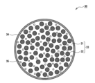
図2は、実施形態の一例である複合粒子30の断面を示す模式図である。負極12は、負極活物質として、少なくとも複合粒子30を含み、好ましくは複合粒子30および炭素材料を含む。負極活物質として、複合粒子30と炭素材料を併用すると、高容量と優れたサイクル特性を両立しやすくなる。炭素材料の含有量は、負極活物質の総質量に対して、98質量%以下が好ましく、70質量%以上、98質量%以下がより好ましく、75質量%以上、95質量%以下が特に好ましい。
FIG. 2 is a schematic diagram showing a cross section of a composite particle 30 that is an example of an embodiment. The negative electrode 12 contains at least composite particles 30, preferably composite particles 30 and a carbon material, as a negative electrode active material. When the composite particles 30 and a carbon material are used together as the negative electrode active material, it becomes easier to achieve both high capacity and excellent cycle characteristics. The content of the carbon material is preferably 98% by mass or less, more preferably 70% by mass or more and 98% by mass or less, and particularly preferably 75% by mass or more and 95% by mass or less, relative to the total mass of the negative electrode active material.
炭素材料としては、黒鉛、易黒鉛化炭素(ソフトカーボン)、難黒鉛化炭素(ハードカーボン)等が例示できる。中でも、充放電の安定性に優れ、不可逆容量も少ない黒鉛が好ましい。黒鉛は、塊状人造黒鉛(MAG)、黒鉛化メソフェーズカーボンマイクロビーズ(MCMB)等の人造黒鉛、および鱗片状黒鉛、塊状黒鉛、土状黒鉛等の天然黒鉛のいずれであってもよい。
Examples of carbon materials include graphite, graphitizable carbon (soft carbon), and non-graphitizable carbon (hard carbon). Among them, graphite is preferable because it has excellent charging/discharging stability and low irreversible capacity. Graphite may be any of artificial graphite such as massive artificial graphite (MAG) and graphitized mesophase carbon microbeads (MCMB), and natural graphite such as flake graphite, massive graphite, and earthy graphite.
図2に示すように、複合粒子30は、リチウムアルミネート相31と、リチウムアルミネート相31内に分散しているシリコン相32とを含む。また、複合粒子30は、リチウムアルミネート相31およびシリコン相32からなる母粒子33の表面に形成された導電層34を含むことが好ましい。母粒子33は、リチウムアルミネート相31のマトリックス中に微細なシリコン相32が分散した海島構造を有する。また、母粒子33の内部には空隙35が存在しているが、母粒子33の空隙量は少なく、本実施形態では、初回充放電前における空隙率が25%以下である。
As shown in FIG. 2 , the composite particles 30 include a lithium aluminate phase 31 and silicon phases 32 dispersed within the lithium aluminate phase 31 . Composite particle 30 preferably includes conductive layer 34 formed on the surface of base particle 33 composed of lithium aluminate phase 31 and silicon phase 32 . The mother particles 33 have a sea-island structure in which fine silicon phases 32 are dispersed in a matrix of a lithium aluminate phase 31 . Also, although there are voids 35 inside the base particles 33, the amount of voids in the base particles 33 is small, and in the present embodiment, the porosity before the first charge/discharge is 25% or less.
リチウムアルミネート相31は、LSX粒子中のリチウムシリケート相よりも耐アルカリ性に優れている。このため、負極活物質として複合粒子30を用いた場合、LSXを用いた場合と比較して初期充電時におけるLiイオンとの副反応が抑制され、副反応に伴う負極活物質の劣化および劣化に伴う初期容量の低下が抑制される。すなわち、初期の充放電効率の低下が高度に抑制される。
The lithium aluminate phase 31 has better alkali resistance than the lithium silicate phase in the LSX particles. Therefore, when the composite particles 30 are used as the negative electrode active material, the side reaction with Li ions during the initial charge is suppressed compared to the case of using LSX, and the negative electrode active material deteriorates and deteriorates due to the side reaction. The accompanying decrease in initial capacity is suppressed. That is, the decrease in initial charge/discharge efficiency is highly suppressed.
複合粒子30は、実質的に、リチウムシリケートおよびSiO2を含まなくてもよい。複合粒子30は、リチウムシリケートおよびSiO2を含んでもよいが、少量であることが望ましい。複合粒子30中のリチウムシリケートおよびSiO2を合計した含有量は、例えば、3質量%以下である。
Composite particles 30 may be substantially free of lithium silicate and SiO 2 . Composite particles 30 may include lithium silicate and SiO 2 , but preferably in small amounts. The total content of lithium silicate and SiO 2 in composite particles 30 is, for example, 3% by mass or less.
複合粒子30において、酸素以外の元素の総質量に対するアルミニウム(Al)の含有率(MAl)は、10質量%以上、47質量%以下が好ましい。また、酸素以外の元素の総質量に対するリチウム(Li)の含有率(MLi)は、0.7質量%以上、13.5質量%以下が好ましい。Alの含有率(MAl)およびLiの含有率(MLi)が上記範囲内である場合、安定性とイオン伝導性に優れるアルミネート相が得られやすい。なお、上記の安定性は、化学的安定性(耐アルカリ性)および熱的安定性の両方を含む。
In the composite particles 30, the content of aluminum (Al) relative to the total mass of elements other than oxygen (MAl) is preferably 10% by mass or more and 47% by mass or less. Also, the content of lithium (Li) relative to the total mass of elements other than oxygen (MLi) is preferably 0.7% by mass or more and 13.5% by mass or less. When the Al content (MAl) and the Li content (MLi) are within the above ranges, an aluminate phase having excellent stability and ionic conductivity is likely to be obtained. The above stability includes both chemical stability (alkali resistance) and thermal stability.
Alの含有率(MAl)に対するLiの含有率(MLi)の比(MLi/MAl)は、リチウムアルミネート相31の安定性とイオン導電性の観点から、0.01以上、0.50以下が好ましく、0.05以上、0.25以下がより好ましい。含有率(MAl)は、11.5質量%以上、45.5質量%以下がより好ましい。含有率(MLi)は、1.0質量%以上、9.5質量%以下がより好ましく、1.5質量%以上、3.5質量%以下が特に好ましい。
The ratio (MLi/MAl) of the Li content (MLi) to the Al content (MAl) is 0.01 or more and 0.50 or less from the viewpoint of the stability and ionic conductivity of the lithium aluminate phase 31. It is preferably 0.05 or more and 0.25 or less. The content (MAl) is more preferably 11.5% by mass or more and 45.5% by mass or less. The content (MLi) is more preferably 1.0% by mass or more and 9.5% by mass or less, and particularly preferably 1.5% by mass or more and 3.5% by mass or less.
複合粒子30において、酸素以外の元素の総質量に対するシリコン(Si)の含有率(MSi)は、40質量%以上、90質量%以下が好ましく、50.8質量%以上、85.5質量%以下がより好ましい。この場合、高容量と良好なサイクル特性の両立を実現しやすい。Siの含有率(MSi)は,複合粒子30中のシリコン相32を構成するSiの量である。
In the composite particle 30, the content of silicon (Si) relative to the total mass of elements other than oxygen (MSi) is preferably 40% by mass or more and 90% by mass or less, and 50.8% by mass or more and 85.5% by mass or less. is more preferred. In this case, it is easy to achieve both high capacity and good cycle characteristics. The Si content (MSi) is the amount of Si that constitutes the silicon phase 32 in the composite particle 30 .
複合粒子30(母粒子33)のX線回折(XRD)測定により得られるXRDパターンにおいて、2θ=x°付近に、リチウムアルミネート相に由来するピークが観測される。x°は、19.4°、22.3°、31.9°、34.3°、および37.5°からなる群より選択される少なくとも1つである。XRD測定のX線には、CuのKα線が用いられる。なお、本明細書中、x°付近であるとは、例えば、x±1°の範囲内であることを意味する。
In the XRD pattern obtained by X-ray diffraction (XRD) measurement of the composite particles 30 (mother particles 33), a peak derived from the lithium aluminate phase is observed near 2θ=x°. x° is at least one selected from the group consisting of 19.4°, 22.3°, 31.9°, 34.3° and 37.5°. Kα rays of Cu are used as X-rays for XRD measurement. In this specification, being near x° means, for example, within the range of x±1°.
リチウムアルミネート相31内には、結晶性の高い微細なAl2O3相が分散してもよい。Al2O3相は、例えば、リチウムアルミネート相31のマトリクス中に島状に分布している。この場合、シリコン相32の膨張収縮に伴うリチウムアルミネート相31の膨張や割れが抑制されやすく、サイクル特性の改善効果が高まる。Al2O3相が存在する場合、X線回折測定により得られる複合粒子のX線回折パターンにおいて、2θ=25.4°付近に、Al2O3相に由来するピークが観測され得る。複合粒子30中のAl2O3相の含有量は、例えば、10質量%以下である。
A fine Al 2 O 3 phase with high crystallinity may be dispersed in the lithium aluminate phase 31 . The Al 2 O 3 phase is distributed like islands in the matrix of the lithium aluminate phase 31, for example. In this case, expansion and cracking of the lithium aluminate phase 31 due to expansion and contraction of the silicon phase 32 are easily suppressed, and the effect of improving the cycle characteristics is enhanced. When the Al 2 O 3 phase is present, a peak derived from the Al 2 O 3 phase can be observed near 2θ=25.4° in the X-ray diffraction pattern of the composite particles obtained by X-ray diffraction measurement. The content of the Al 2 O 3 phase in the composite particles 30 is, for example, 10% by mass or less.
図3に、複合粒子30(母粒子33)のXRDパターンの一例を示す。図3中の実線は、MAl/MLiが大きいAlリッチの複合粒子30のXRDパターンを示す。図3中の破線は、MAl/MLiが小さいLiリッチの複合粒子30のXRDパターンを示す。いずれの場合も、2θ=28°付近に、シリコン相32のSi(111)面に由来するピークが観察される。Alリッチの複合粒子30では、2θ=25.4°付近に、Al2O3相に由来するピークが観察される。
FIG. 3 shows an example of the XRD pattern of the composite particles 30 (mother particles 33). The solid line in FIG. 3 indicates the XRD pattern of the Al-rich composite particles 30 with a large MAl/MLi. The dashed line in FIG. 3 indicates the XRD pattern of the Li-rich composite particles 30 with a small MAl/MLi. In either case, a peak derived from the Si (111) plane of the silicon phase 32 is observed near 2θ=28°. In the Al-rich composite particles 30, a peak derived from the Al 2 O 3 phase is observed near 2θ=25.4°.
図3中の(i)~(v)は、リチウムアルミネートに由来するピークを示す。Alリッチの複合粒子30では、2θ=19.4°付近および2θ=31.9°付近に、リチウムアルミネート相31のLi2Al4O7およびLiAlO2に由来するピークが観察される(図3中の(i)および(ii)のピーク)。また、Alリッチの複合粒子30では、2θ=37.5°付近に、Li2Al4O7およびLiAl5O8に由来するピークが観察される(図3中の(iii)のピーク)。Liリッチの複合粒子30では、2θ=22.3°付近および2θ=34.3付近に、リチウムアルミネート相31のLiAlO2およびLi5AlO4に由来するピークが観察される(図3中の(iv)および(v)のピーク)。
(i) to (v) in FIG. 3 indicate peaks derived from lithium aluminate. In the Al-rich composite particles 30, peaks derived from Li 2 Al 4 O 7 and LiAlO 2 of the lithium aluminate phase 31 are observed near 2θ = 19.4° and 2θ = 31.9° (Fig. (i) and (ii) peaks in 3). In the Al-rich composite particles 30, peaks derived from Li 2 Al 4 O 7 and LiAl 5 O 8 are observed near 2θ=37.5° (peak (iii) in FIG. 3). In the Li-rich composite particles 30, peaks derived from LiAlO 2 and Li 5 AlO 4 of the lithium aluminate phase 31 are observed near 2θ = 22.3° and 2θ = 34.3 (Fig. 3 (iv) and (v) peaks).
複合粒子30の母粒子33は、海部であるリチウムアルミネート相31内に、島部である微細なシリコン相32が分散した海島構造を有する。リチウムアルミネート相31は良好なイオン伝導性を有し、リチウムアルミネート相31を介してシリコン相32によるLiイオンの吸蔵および放出がスムーズに行われる。また、リチウムアルミネート相31によりシリコン相32の膨張収縮の影響が緩和される。リチウムアルミネート相31は、非晶質であってもよく、この場合、シリコン相32の膨張収縮の影響をより効果的に緩和できる。
The base particles 33 of the composite particles 30 have a sea-island structure in which fine silicon phases 32, which are islands, are dispersed in lithium aluminate phases 31, which are seas. The lithium aluminate phase 31 has good ionic conductivity, and absorption and release of Li ions by the silicon phase 32 through the lithium aluminate phase 31 are performed smoothly. In addition, the lithium aluminate phase 31 mitigates the influence of expansion and contraction of the silicon phase 32 . The lithium aluminate phase 31 may be amorphous, in which case the effects of expansion and contraction of the silicon phase 32 can be more effectively mitigated.
複合粒子30では、例えば、リチウムアルミネート相31とシリコン相32とを含む複数の一次粒子が結合して二次粒子を構成している。複合粒子30(二次粒子)の平均粒径は、例えば、1μm以上、25μm以下であり、4μm以上、15μm以下であってもよい。この場合、充放電に伴う複合粒子30の体積変化による応力を緩和しやすく、良好なサイクル特性を得やすくなる。複合粒子30の表面積も適度な大きさになり、非水電解質との副反応による容量低下も抑制される。
In the composite particles 30, for example, a plurality of primary particles including a lithium aluminate phase 31 and a silicon phase 32 are combined to form secondary particles. The average particle diameter of the composite particles 30 (secondary particles) is, for example, 1 μm or more and 25 μm or less, and may be 4 μm or more and 15 μm or less. In this case, the stress due to the volume change of the composite particles 30 due to charging and discharging is easily alleviated, and good cycle characteristics are easily obtained. The surface area of the composite particles 30 also has an appropriate size, and the decrease in capacity due to side reactions with the non-aqueous electrolyte is also suppressed.
複合粒子30の平均粒径とは、レーザー回折散乱法で測定される粒度分布において、体積積算値が50%となる粒径(体積平均粒径)を意味する。測定装置には、例えば、株式会社堀場製作所(HORIBA)製「LA-750」を用いることができる。母粒子33の表面が導電層34で覆われている場合、導電層34の厚みは、実質上、複合粒子30の平均粒径に影響しない程度に薄いため、導電層34を有する複合粒子30の平均粒径を複合粒子30の平均粒径と見なしてよい。
The average particle size of the composite particles 30 means the particle size (volume average particle size) at which the volume integrated value is 50% in the particle size distribution measured by the laser diffraction scattering method. For example, "LA-750" manufactured by HORIBA, Ltd. can be used as the measuring device. When the surface of the base particle 33 is covered with the conductive layer 34, the thickness of the conductive layer 34 is substantially thin enough not to affect the average particle diameter of the composite particle 30. Therefore, the composite particle 30 having the conductive layer 34 The average particle size may be considered the average particle size of the composite particles 30 .
複合粒子30は、以下の手法により、電池から取り出すことができる。まず、完全放電状態の電池を解体して負極を取り出し、負極を無水エチルメチルカーボネート又はジメチルカーボネートで洗浄し、非水電解質成分を除去する。負極芯体である銅箔から負極合剤層を剥がし取り、合剤層を乳鉢で粉砕して試料粉を得る。次に、試料粉を乾燥雰囲気中で1時間乾燥し、弱く煮立てた6M塩酸に10分間浸漬して、複合粒子以外に由来する元素を取り除く。次に、イオン交換水で試料粉を洗浄し、濾別して200℃で1時間乾燥する。その後、酸素雰囲気中、900℃に加熱して導電層34を除去することで、母粒子33だけを単離することができる。なお、完全放電状態とは、放電深度(DOD)が90%以上(充電状態(SOC)が10%以下)の状態である。
The composite particles 30 can be taken out from the battery by the following method. First, a battery in a completely discharged state is disassembled, the negative electrode is taken out, and the negative electrode is washed with anhydrous ethyl methyl carbonate or dimethyl carbonate to remove non-aqueous electrolyte components. The negative electrode mixture layer is peeled off from the copper foil that is the negative electrode core, and the mixture layer is pulverized in a mortar to obtain a sample powder. Next, the sample powder is dried in a dry atmosphere for 1 hour and immersed in weakly boiled 6M hydrochloric acid for 10 minutes to remove elements derived from other than the composite particles. Next, the sample powder is washed with deionized water, separated by filtration, and dried at 200° C. for 1 hour. Thereafter, by heating to 900° C. in an oxygen atmosphere to remove the conductive layer 34, only the mother particles 33 can be isolated. Note that the fully discharged state is a state in which the depth of discharge (DOD) is 90% or more (the state of charge (SOC) is 10% or less).
[リチウムアルミネート相]
リチウムアルミネート相31は、Li、Al、Oを含む複合酸化物の相である。リチウムアルミネートにおけるAlに対するOの原子比(O/Al)は、例えば、1.6以上、4以下である。また、リチウムアルミネートにおけるAlに対するLiの原子比(Li/Al)は、例えば、1/5以上、5以下である。当該各原子比が上記範囲内である場合、リチウムアルミネート相31の安定性とイオン伝導性がより良好になる。 [Lithium aluminate phase]
Thelithium aluminate phase 31 is a complex oxide phase containing Li, Al and O. The atomic ratio of O to Al (O/Al) in lithium aluminate is, for example, 1.6 or more and 4 or less. Further, the atomic ratio of Li to Al (Li/Al) in lithium aluminate is, for example, 1/5 or more and 5 or less. When each atomic ratio is within the above range, the stability and ionic conductivity of the lithium aluminate phase 31 are improved.
リチウムアルミネート相31は、Li、Al、Oを含む複合酸化物の相である。リチウムアルミネートにおけるAlに対するOの原子比(O/Al)は、例えば、1.6以上、4以下である。また、リチウムアルミネートにおけるAlに対するLiの原子比(Li/Al)は、例えば、1/5以上、5以下である。当該各原子比が上記範囲内である場合、リチウムアルミネート相31の安定性とイオン伝導性がより良好になる。 [Lithium aluminate phase]
The
リチウムアルミネートの組成は、式:LiuAlO(3+u)/2で表すことができる。作製し易さ、安定性、およびイオン伝導性等の観点から、式中のuは、例えば、0超、5以下であり、0超、1以下であってもよい。u=1/5の場合、LiAl5O8で表すことができ、u=1/2の場合、Li2Al4O7で表すことができる。u=1の場合、LiAlO2で表すことができ、u=5の場合、Li5AlO4で表すことができる。リチウムアルミネート相31は、例えば、LiAl5O8、Li2Al4O7、LiAlO2、およびLi5AlO4からなる群より選択される少なくとも1種を含む。
The composition of lithium aluminate can be represented by the formula: Li u AlO (3+u)/2 . From the viewpoint of ease of production, stability, ionic conductivity, etc., u in the formula is, for example, greater than 0 and 5 or less, or may be greater than 0 and 1 or less. When u=1/5, it can be expressed as LiAl 5 O 8 , and when u=1/2, it can be expressed as Li 2 Al 4 O 7 . When u=1, it can be represented by LiAlO 2 , and when u=5, it can be represented by Li 5 AlO 4 . The lithium aluminate phase 31 contains, for example, at least one selected from the group consisting of LiAl 5 O 8 , Li 2 Al 4 O 7 , LiAlO 2 and Li 5 AlO 4 .
リチウムアルミネート相31には、Li、Al、Oに加えて、少なくともホウ素(B)が含有されている。リチウムアルミネート相31に所定量のBを添加することにより、複合粒子30の空隙35が減少してサイクル特性が効果的に改善される。所定量のBを添加すると、リチウムアルミネートの融点が下がって焼成により緻密で空隙35の少ないリチウムアルミネート相31が形成されると考えられる。
The lithium aluminate phase 31 contains at least boron (B) in addition to Li, Al, and O. By adding a predetermined amount of B to the lithium aluminate phase 31, the voids 35 of the composite particles 30 are reduced and the cycle characteristics are effectively improved. It is considered that when a predetermined amount of B is added, the melting point of lithium aluminate is lowered, and the lithium aluminate phase 31 that is dense and has few voids 35 is formed by firing.
リチウムアルミネート相31には、更に他の元素Mが含有されていてもよい。元素Mは、例えば、ナトリウム(Na)、カリウム(K)、カルシウム(Ca)、マグネシウム(Mg)、ジルコニウム(Zr)、鉄(Fe)、リン(P)、およびランタン(La)からなる群より選択される少なくとも1種である。リチウムアルミネート相31中に含まれるBおよび元素Mは、化合物を形成していてもよい。
The lithium aluminate phase 31 may further contain another element M. Element M is, for example, from the group consisting of sodium (Na), potassium (K), calcium (Ca), magnesium (Mg), zirconium (Zr), iron (Fe), phosphorus (P), and lanthanum (La). At least one selected. B and the element M contained in the lithium aluminate phase 31 may form a compound.
リチウムアルミネート相31およびシリコン相32を構成する酸素以外の元素の総質量に対する、Alの含有率(MAl)とBの含有率(MB)の比(MAl/MB)は、1.0以上、30.0以下である。Bに対するAlの比率(MAl/MB)が当該範囲内であれば、母粒子33の内部に形成される空隙35が大きく減少し、空隙35に起因して発生すると考えられる粒子構造の劣化が抑制され、サイクル特性が効果的に改善される。
The ratio (MAl/MB) of the content of Al (MAl) and the content of B (MB) to the total mass of elements other than oxygen constituting the lithium aluminate phase 31 and the silicon phase 32 is 1.0 or more, 30.0 or less. If the ratio of Al to B (MAl/MB) is within this range, the voids 35 formed inside the mother particles 33 are greatly reduced, and deterioration of the grain structure that is thought to occur due to the voids 35 is suppressed. and the cycle characteristics are effectively improved.
比率(MAl/MB)が30.0を超える場合、すなわちAlに対してBが少な過ぎる場合、空隙率が高くなりサイクル特性が大きく低下する。一方、比率(MAl/MB)が1.0未満である場合も、空隙率の上昇の程度は比率(MAl/MB)が30.0を超える場合よりも小さいが、初期充放電効率が大きく低下する。つまり、比率(MAl/MB)が1.0以上、30.0以下である場合に、良好な初期充放電効率とサイクル特性を高度に両立できる。また、比率(MAl/MB)は、2.0以上、20.0以下がより好ましい。
When the ratio (MAl/MB) exceeds 30.0, that is, when the amount of B is too small relative to Al, the porosity increases and the cycle characteristics deteriorate significantly. On the other hand, when the ratio (MAl/MB) is less than 1.0, the degree of increase in porosity is smaller than when the ratio (MAl/MB) exceeds 30.0, but the initial charge-discharge efficiency is greatly reduced. do. In other words, when the ratio (MAl/MB) is 1.0 or more and 30.0 or less, both good initial charge/discharge efficiency and cycle characteristics can be achieved at a high level. Moreover, the ratio (MAl/MB) is more preferably 2.0 or more and 20.0 or less.
母粒子33におけるBの含有率(MB)は、Al量との関係で限定されるが、好ましくは1質量%以上、20質量%であり、より好ましくは2質量%以上、15質量%以下である。この場合、サイクル特性の改善効果がより顕著になる。Alの含有率(MAl)は、上記の通り、11.5質量%以上、45.5質量%以下が好ましく、15質量%以上、30質量%以下がより好ましい。
The B content (MB) in the mother particles 33 is limited in relation to the Al content, but is preferably 1% by mass or more and 20% by mass, more preferably 2% by mass or more and 15% by mass or less. be. In this case, the effect of improving cycle characteristics becomes more pronounced. As described above, the Al content (MAl) is preferably 11.5% by mass or more and 45.5% by mass or less, more preferably 15% by mass or more and 30% by mass or less.
複合粒子30は、初回充放電前において、粒子内部の空隙率が25%以下であることが好ましい。導電層34は複合粒子30の空隙率に影響しないので、複合粒子30の空隙率と母粒子33の空隙率は実質的に同じである。空隙率は、複合粒子30の粒子断面に占める空隙35の割合を意味し、粒子断面のSEM画像から算出される。負極活物質として空隙率の低い複合粒子30を用いることにより、空隙35に起因して発生すると考えられる粒子構造の劣化が抑制され、電池のサイクル特性が大きく向上する。
The composite particles 30 preferably have a porosity of 25% or less inside the particles before the first charge and discharge. Since the conductive layer 34 does not affect the porosity of the composite particles 30, the porosity of the composite particles 30 and the porosity of the base particles 33 are substantially the same. The porosity means the proportion of the voids 35 in the particle cross section of the composite particle 30, and is calculated from the SEM image of the particle cross section. By using the composite particles 30 with a low porosity as the negative electrode active material, deterioration of the particle structure that is thought to be caused by the voids 35 is suppressed, and the cycle characteristics of the battery are greatly improved.
複合粒子30の空隙率は、20%以下がより好ましく、15%以下が特に好ましい。空隙率の下限値は特に限定されないが、一例としては1%である。空隙35は、例えば、母粒子33の全体に略均一に存在している。図2に模式的に示すように、1つ1つの空隙35は小さく、シリコン相32と同様に、多数の空隙35がリチウムアルミネート相31の全体に分散するように存在していてもよい。
The porosity of the composite particles 30 is more preferably 20% or less, particularly preferably 15% or less. Although the lower limit of the porosity is not particularly limited, it is 1% as an example. The voids 35 are, for example, substantially uniformly present throughout the base particles 33 . As schematically shown in FIG. 2 , each void 35 is small, and many voids 35 may exist so as to be dispersed throughout the lithium aluminate phase 31 , similar to the silicon phase 32 .
複合粒子30の空隙率は、画像解析ソフト(例えば、imageJ)を用いて、粒子断面のSEM画像を2値化処理して空隙35の領域を抽出し、空隙35の総面積を粒子断面の総面積で除することにより算出される。空隙率は粒子10個についての平均値とする。なお、複合粒子30の空隙率は、Bの添加と共に、複合粒子30の焼成温度、焼成時に粒子に加える圧縮力、比率(MLi/MAl)等を調整することによっても、ある程度制御できる。
The porosity of the composite particle 30 is obtained by binarizing the SEM image of the cross section of the particle using image analysis software (eg, imageJ) to extract the area of the void 35, and calculating the total area of the void 35 as the total area of the cross section of the particle. Calculated by dividing by the area. The porosity is an average value for 10 particles. In addition to adding B, the porosity of the composite particles 30 can also be controlled to some extent by adjusting the firing temperature of the composite particles 30, the compressive force applied to the particles during firing, the ratio (MLi/MAl), and the like.
複合粒子30は、300HV以上のビッカース硬度を有することが好ましい。導電層34はビッカース硬度に影響しないため、複合粒子30のビッカース硬度と母粒子33のビッカース硬度は実質的に同じである。複合粒子30が高いビッカース硬度を有する場合、充放電時のシリコン相32の体積変化を抑制しやすく、粒子構造の劣化を低減できる。その結果、サイクル特性の改善効果がより顕著になる。複合粒子30のビッカース硬度は、350HV以上がより好ましく、400HV以上、又は500HV以上であってもよい。
The composite particles 30 preferably have a Vickers hardness of 300HV or more. Since the conductive layer 34 does not affect the Vickers hardness, the Vickers hardness of the composite particles 30 and the Vickers hardness of the base particles 33 are substantially the same. When the composite particles 30 have a high Vickers hardness, it is easy to suppress the volume change of the silicon phase 32 during charging and discharging, and deterioration of the particle structure can be reduced. As a result, the effect of improving cycle characteristics becomes more pronounced. The Vickers hardness of the composite particles 30 is more preferably 350 HV or higher, and may be 400 HV or higher, or 500 HV or higher.
複合粒子30のビッカース硬度は、ビッカース硬度計を用いて測定できる。具体的には、複合粒子30を熱硬化性樹脂に埋め込み、400番の研磨紙で研磨して複合粒子30の断面を表出させる。さらに2000番の研磨紙、バフ研磨で断面を鏡面仕上げする。荷重1kg、保持時間15秒の条件でビッカース硬度を測定する。複合粒子30のビッカース硬度の上限値は特に限定されないが、一例としては1500HVである。
The Vickers hardness of the composite particles 30 can be measured using a Vickers hardness tester. Specifically, the composite particles 30 are embedded in a thermosetting resin and polished with No. 400 abrasive paper to expose the cross section of the composite particles 30 . Further, the cross section is mirror-finished with 2000 abrasive paper and buffing. The Vickers hardness is measured under the conditions of a load of 1 kg and a holding time of 15 seconds. Although the upper limit of the Vickers hardness of the composite particles 30 is not particularly limited, it is 1500 HV as an example.
リチウムアルミネート相31中のLi、Al、B、元素Mの含有量は、例えば、負極合剤層の断面を分析することにより測定することができる。まず、完全放電状態の電池を分解し、負極を取り出し、負極を無水エチルメチルカーボネート又はジメチルカーボネートで洗浄し、非水電解質成分を除去し、乾燥させた後、クロスセクションポリッシャ(CP)を用いて負極合剤層の断面を得る。次に、走査型電子顕微鏡(SEM)を用いて負極合剤層の断面を観察する。
The contents of Li, Al, B, and the element M in the lithium aluminate phase 31 can be measured, for example, by analyzing the cross section of the negative electrode mixture layer. First, a battery in a fully discharged state is disassembled, the negative electrode is taken out, the negative electrode is washed with anhydrous ethyl methyl carbonate or dimethyl carbonate to remove non-aqueous electrolyte components, dried, and then a cross section polisher (CP) is used. A cross section of the negative electrode mixture layer is obtained. Next, a cross section of the negative electrode mixture layer is observed using a scanning electron microscope (SEM).
リチウムアルミネート相31における各元素の含有量は、以下のいずれかの手法により測定される。また、各元素の含有量からリチウムアルミネート相31の組成が分かる。
The content of each element in the lithium aluminate phase 31 is measured by one of the following methods. Also, the composition of the lithium aluminate phase 31 can be known from the content of each element.
[エネルギー分散型X線(EDX)]
負極合剤層の反射電子像の断面画像から、粒子の最大径が5μm以上の複合粒子30を無作為に10個選び出し、それぞれについてEDXによる元素のマッピング分析を行う。画像解析ソフトを用いて対象となる元素の含有面積を算出する。観察倍率は2000~20000倍が望ましい。粒子10個に含まれる所定の元素の含有面積の測定値を平均する。得られた平均値から対象となる元素の含有量が算出される。 [Energy dispersive X-ray (EDX)]
Ten composite particles 30 having a maximum particle diameter of 5 μm or more are randomly selected from the cross-sectional image of the backscattered electron image of the negative electrode mixture layer, and elemental mapping analysis is performed on each of the composite particles 30 by EDX. The area containing the target element is calculated using image analysis software. The observation magnification is desirably 2000 to 20000 times. The measured values of the content area of a given element contained in 10 particles are averaged. The content of the target element is calculated from the obtained average value.
以下に、望ましい断面SEM-EDX分析の測定条件を示す。
加工装置:JEOL製、SM-09010(Cross Section Polisher)
加工条件:加速電圧6kV
電流値:140μA
真空度:1×10⁻³~2×10⁻³Pa
測定装置:HITACHI製、電子顕微鏡SU-70
分析時加速電圧:10kV
フィールド:フリーモード
プローブ電流モード:Medium
プローブ電流範囲:High
アノード Ap.:3
OBJ Ap.:2
分析エリア:1μm四方
分析ソフト:EDAX Genesis
CPS:20500
Lsec:50
時定数:3.2 Desirable cross-sectional SEM-EDX analysis measurement conditions are shown below.
Processing equipment: SM-09010 (Cross Section Polisher) manufactured by JEOL
Processing conditions: acceleration voltage 6 kV
Current value: 140μA
Degree of vacuum: 1×10 −3 to 2×10 −3 Pa
Measuring device: Electron microscope SU-70 manufactured by HITACHI
Acceleration voltage during analysis: 10 kV
Field: Free Mode Probe Current Mode: Medium
Probe current range: High
Anode Ap.: 3
OBJ App.: 2
Analysis area: 1 μm square Analysis software: EDAX Genesis
CPS: 20500
Lsec: 50
Time constant: 3.2
[オージェ電子分光(AES)]
負極合剤層の反射電子像の断面画像から、粒子の最大径が5μm以上の複合粒子30を無作為に10個選び出し、それぞれについてAES分析装置(例えば、日本電子社製、JAMP-9510F)を用いて元素の定性定量分析を行う。測定条件は、例えば、加速電圧10kV、ビーム電流10nA、分析領域20μmφとすればよい。粒子10個に含まれる所定の元素の含有量を平均して含有量が算出される。 [Auger Electron Spectroscopy (AES)]
10 composite particles 30 having a maximum particle diameter of 5 μm or more are randomly selected from the cross-sectional image of the backscattered electron image of the negative electrode mixture layer, and an AES analyzer (for example, JAMP-9510F manufactured by JEOL Ltd.) is analyzed for each of them. Perform qualitative and quantitative analysis of elements using Measurement conditions may be, for example, an acceleration voltage of 10 kV, a beam current of 10 nA, and an analysis area of 20 μmφ. The content is calculated by averaging the content of a predetermined element contained in 10 particles.
なお、EDX分析やAES分析は、複合粒子30の断面の周端縁から1μm以上内側の範囲に対して行われる。
Note that the EDX analysis and AES analysis are performed on a range of 1 μm or more inside from the peripheral edge of the cross section of the composite particle 30 .
[誘導結合プラズマ発光分光分析法(ICP)]
複合粒子30の試料を、加熱した酸溶液(フッ化水素酸、硝酸、および硫酸の混酸)中で全溶解し、溶液残渣の炭素を濾過して除去する。その後、得られた濾液をICPで分析して、各元素のスペクトル強度を測定する。続いて、市販されている元素の標準溶液を用いて検量線を作成し、複合粒子30に含まれる各元素の含有量を算出する。 [Inductively Coupled Plasma Emission Spectroscopy (ICP)]
A sample of composite particles 30 is completely dissolved in a heated acid solution (mixed acid of hydrofluoric acid, nitric acid, and sulfuric acid), and the carbon remaining in the solution is removed by filtration. The obtained filtrate is then analyzed by ICP to measure the spectral intensity of each element. Subsequently, a calibration curve is created using a commercially available standard solution of the elements, and the content of each element contained in the composite particles 30 is calculated.
各元素の定量は、電子マイクロアナライザー(EPMA)、レーザアブレーションICP質量分析(LA-ICP-MS)、X線光電子分光分析(XPS)等を用いて行うこともできる。また、複合粒子30に含まれるB、Na、K、およびAlの含有量は、JIS R3105(1995)(ほうけい酸ガラスの分析方法)に準拠して定量分析してもよい。Caの含有量は、JIS R3101(1995)(ソーダ石灰ガラスの分析方法)に準拠して定量分析してもよい。
Each element can be quantified using an electron microanalyzer (EPMA), laser ablation ICP mass spectrometry (LA-ICP-MS), X-ray photoelectron spectroscopy (XPS), etc. Also, the contents of B, Na, K, and Al contained in the composite particles 30 may be quantitatively analyzed in accordance with JIS R3105 (1995) (analysis method for borosilicate glass). The Ca content may be quantitatively analyzed according to JIS R3101 (1995) (analysis method for soda-lime glass).
複合粒子30に含まれる炭素含有量は、炭素・硫黄分析装置(例えば、株式会社堀場製作所製のEMIA-520型)を用いて測定できる。磁性ボードに試料を測り取り、助燃剤を加え、1350℃に加熱された燃焼炉(キャリアガス:酸素)に挿入し、燃焼時に発生した二酸化炭素ガス量を赤外線吸収により検出する。検量線は、例えば、Bureauof Analysed Samples.Ltd製の炭素鋼(炭素含有量0.49%)を用いて作成し、試料の炭素含有量を算出する(高周波誘導加熱炉燃焼-赤外線吸収法)。
The carbon content contained in the composite particles 30 can be measured using a carbon/sulfur analyzer (for example, EMIA-520 model manufactured by Horiba, Ltd.). A sample is measured on a magnetic board, a combustion improver is added, the board is inserted into a combustion furnace (carrier gas: oxygen) heated to 1350° C., and the amount of carbon dioxide gas generated during combustion is detected by infrared absorption. A standard curve is obtained, for example, from Bureau of Analyzed Samples. Ltd. carbon steel (carbon content 0.49%) is used, and the carbon content of the sample is calculated (high-frequency induction heating furnace combustion-infrared absorption method).
複合粒子30に含まれる酸素含有量は、酸素・窒素・水素分析装置(例えば、株式会社堀場製作所製のEGMA-830型)を用いて測定できる。Niカプセルに試料を入れ、フラックスとなるSnペレットおよびNiペレットとともに、電力5.75kWで加熱された炭素坩堝に投入し、放出される一酸化炭素ガスを検出する。検量線は、標準試料Y2O3を用いて作成し、試料の酸素含有量を算出する(不活性ガス融解-非分散型赤外線吸収法)。
The oxygen content contained in the composite particles 30 can be measured using an oxygen/nitrogen/hydrogen analyzer (eg, Model EGMA-830 manufactured by Horiba, Ltd.). A sample is placed in a Ni capsule, which is put into a carbon crucible heated with a power of 5.75 kW together with Sn pellets and Ni pellets as fluxes, and carbon monoxide gas released is detected. A calibration curve is prepared using a standard sample Y 2 O 3 , and the oxygen content of the sample is calculated (inert gas fusion-nondispersive infrared absorption method).
複合粒子30中のシリコン相32を構成するSi量は、Si-NMRを用いて定量することができる。以下に、望ましいSi-NMRの測定条件を示す。
測定装置:バリアン社製、固体核磁気共鳴スペクトル測定装置(INOVA‐400)
プローブ:Varian 7mm CPMAS-2
MAS:4.2kHz
MAS速度:4kHz
パルス:DD(45°パルス+シグナル取込時間1Hデカップル)
繰り返し時間:1200sec~3000sec
観測幅:100kHz
観測中心:-100ppm付近
シグナル取込時間:0.05sec
積算回数:560
試料量:207.6mg The amount of Si constituting thesilicon phase 32 in the composite particles 30 can be quantified using Si-NMR. Desirable Si-NMR measurement conditions are shown below.
Measurement device: Solid-state nuclear magnetic resonance spectrometer (INOVA-400) manufactured by Varian
Probe: Varian 7mm CPMAS-2
MAS: 4.2kHz
MAS speed: 4kHz
Pulse: DD (45° pulse + signal acquisition time 1H decouple)
Repeat time: 1200sec-3000sec
Observation width: 100 kHz
Observation center: Around -100 ppm Signal capture time: 0.05 sec
Cumulative count: 560
Sample amount: 207.6 mg
測定装置:バリアン社製、固体核磁気共鳴スペクトル測定装置(INOVA‐400)
プローブ:Varian 7mm CPMAS-2
MAS:4.2kHz
MAS速度:4kHz
パルス:DD(45°パルス+シグナル取込時間1Hデカップル)
繰り返し時間:1200sec~3000sec
観測幅:100kHz
観測中心:-100ppm付近
シグナル取込時間:0.05sec
積算回数:560
試料量:207.6mg The amount of Si constituting the
Measurement device: Solid-state nuclear magnetic resonance spectrometer (INOVA-400) manufactured by Varian
Probe: Varian 7mm CPMAS-2
MAS: 4.2kHz
MAS speed: 4kHz
Pulse: DD (45° pulse + signal acquisition time 1H decouple)
Repeat time: 1200sec-3000sec
Observation width: 100 kHz
Observation center: Around -100 ppm Signal capture time: 0.05 sec
Cumulative count: 560
Sample amount: 207.6 mg
[シリコン相]
シリコン相32は、Si単体の相であり、電池の充放電に伴ってLiイオンの吸蔵と放出を繰り返す。シリコン相32が関与するファラデー反応によって容量が発現する。シリコン相32は、容量が大きいため、充放電に伴う膨張と収縮の程度も大きいが、シリコン相32はリチウムアルミネート相31内に分散している。このため、シリコン相32の膨張と収縮による応力はリチウムアルミネート相31によって緩和される。 [Silicon phase]
Thesilicon phase 32 is a phase of simple Si, and repeats intercalation and deintercalation of Li ions as the battery is charged and discharged. Capacitance is developed by the Faradaic reaction involving the silicon phase 32 . Since the silicon phase 32 has a large capacity, the silicon phase 32 is dispersed in the lithium aluminate phase 31 although the degree of expansion and contraction due to charging and discharging is large. Therefore, stress due to expansion and contraction of the silicon phase 32 is relieved by the lithium aluminate phase 31 .
シリコン相32は、Si単体の相であり、電池の充放電に伴ってLiイオンの吸蔵と放出を繰り返す。シリコン相32が関与するファラデー反応によって容量が発現する。シリコン相32は、容量が大きいため、充放電に伴う膨張と収縮の程度も大きいが、シリコン相32はリチウムアルミネート相31内に分散している。このため、シリコン相32の膨張と収縮による応力はリチウムアルミネート相31によって緩和される。 [Silicon phase]
The
シリコン相32は、例えば、複数の結晶子で構成されている。複合粒子30(母粒子33)のXRD測定により得られるSi(111)面の回折ピークの半値幅からシェラーの式により算出されるシリコン相32の結晶子サイズは、30nm以下が好ましく、20nm以下がより好ましく、15nm以下が特に好ましい。この場合、充放電に伴うシリコン相32の膨張収縮による複合粒子30の体積変化を小さくでき、サイクル特性の改善効果がより顕著になる。
The silicon phase 32 is composed of, for example, a plurality of crystallites. The crystallite size of the silicon phase 32 calculated by Scherrer's formula from the half width of the diffraction peak of the Si (111) plane obtained by XRD measurement of the composite particle 30 (mother particle 33) is preferably 30 nm or less, and 20 nm or less. More preferably, 15 nm or less is particularly preferable. In this case, the volume change of the composite particles 30 due to the expansion and contraction of the silicon phase 32 due to charging and discharging can be reduced, and the effect of improving the cycle characteristics becomes more pronounced.
シリコン相32の結晶子サイズの下限値は、特に限定されないが、一例としては1nmである。シリコン相32の好適な結晶子サイズの一例は、1nm以上、15nm以下であり、5nm以上、11nm以下であってもよい。シリコン相32の結晶子サイズが1nm以上である場合、例えば、シリコン相32の表面積を小さく抑えることができるため、不可逆容量の生成を伴うシリコン相32の劣化を生じ難い。結晶子サイズが15nm以下である場合、シリコン相32の膨張収縮を均一化しやすく、複合粒子30に生じる応力が効果的に緩和される。
Although the lower limit of the crystallite size of the silicon phase 32 is not particularly limited, it is 1 nm as an example. An example of a suitable crystallite size of the silicon phase 32 is 1 nm or more and 15 nm or less, and may be 5 nm or more and 11 nm or less. When the crystallite size of the silicon phase 32 is 1 nm or more, for example, the surface area of the silicon phase 32 can be kept small, so that the deterioration of the silicon phase 32 accompanied by the generation of irreversible capacitance is less likely to occur. When the crystallite size is 15 nm or less, the expansion and contraction of the silicon phase 32 are likely to be uniform, and the stress generated in the composite particles 30 is effectively relieved.
シリコン相32は、例えば、少なくとも初回充電前において粒子状である。粒子状のシリコン相32の平均粒径は、500nm以下が好ましく、200nm以下がより好ましく、50nm以下が特に好ましい。シリコン相32の平均粒径は、初回充電後において、400nm以下が好ましく、100nm以下がより好ましい。シリコン相32を微細化して分散させることにより、充放電時の複合粒子30の体積変化が小さくなり、複合粒子30の構造安定性が更に向上する。シリコン相32の平均粒径は、SEMにより得られる複合粒子30の断面画像を用いて測定される。具体的には、シリコン相32の平均粒径は、任意の100個のシリコン相32の最大径を平均して求められる。
The silicon phase 32 is, for example, particulate at least before the initial charge. The average particle size of the particulate silicon phase 32 is preferably 500 nm or less, more preferably 200 nm or less, and particularly preferably 50 nm or less. The average grain size of the silicon phase 32 is preferably 400 nm or less, more preferably 100 nm or less after the initial charge. By miniaturizing and dispersing the silicon phase 32, the volume change of the composite particles 30 during charging and discharging is reduced, and the structural stability of the composite particles 30 is further improved. The average particle size of the silicon phase 32 is measured using a cross-sectional image of the composite particles 30 obtained by SEM. Specifically, the average grain size of the silicon phase 32 is obtained by averaging the maximum diameters of arbitrary 100 silicon phases 32 .
複合粒子30におけるシリコン相32の含有率は、高容量化の観点から、30質量%以上が好ましく、35質量%以上がより好ましく、55質量%以上が特に好ましい。シリコン相32の含有率の上限は、良好なサイクル特性確保の観点から、95質量%以下が好ましく、75質量%以下がより好ましく、70質量%以下が特に好ましい。この場合、リチウムアルミネート相31に覆われずに複合粒子30の表面に露出するシリコン相32が減少して、非水電解質とシリコン相32の副反応も抑制される。
From the viewpoint of increasing the capacity, the content of the silicon phase 32 in the composite particles 30 is preferably 30% by mass or more, more preferably 35% by mass or more, and particularly preferably 55% by mass or more. From the viewpoint of ensuring good cycle characteristics, the upper limit of the content of the silicon phase 32 is preferably 95% by mass or less, more preferably 75% by mass or less, and particularly preferably 70% by mass or less. In this case, the silicon phase 32 exposed on the surface of the composite particle 30 without being covered with the lithium aluminate phase 31 is reduced, and the side reaction between the non-aqueous electrolyte and the silicon phase 32 is also suppressed.
[導電層]
複合粒子30は、上記の通り、リチウムアルミネート相31とシリコン相32からなる母粒子33の表面に形成された導電層34を有することが好ましい。導電層34は、母粒子33の表面の少なくとも一部を覆い、好ましくは実質的に母粒子33の表面全体を覆っている。導電層34は、導電性材料を含む薄膜層であって、複合粒子30の導電性を向上させる。導電層34の厚みは、複合粒子30の平均粒径に影響しない程度に薄いことが好ましい。導電層34の厚みは、導電性の確保とLiイオンの拡散性を考慮すると、1nm以上、200nm以下が好ましく、5nm以上、100nm以下がより好ましい。導電層34の厚みは、SEM又は透過型電子顕微鏡(TEM)を用いた複合粒子の断面観察により計測できる。 [Conductive layer]
As described above, composite particle 30 preferably hasconductive layer 34 formed on the surface of base particle 33 composed of lithium aluminate phase 31 and silicon phase 32 . The conductive layer 34 covers at least part of the surface of the base particle 33 , preferably substantially covers the entire surface of the base particle 33 . The conductive layer 34 is a thin film layer containing a conductive material and improves the conductivity of the composite particles 30 . The thickness of the conductive layer 34 is preferably thin enough not to affect the average particle size of the composite particles 30 . The thickness of the conductive layer 34 is preferably 1 nm or more and 200 nm or less, more preferably 5 nm or more and 100 nm or less, in consideration of ensuring conductivity and diffusibility of Li ions. The thickness of the conductive layer 34 can be measured by cross-sectional observation of the composite particles using SEM or transmission electron microscope (TEM).
複合粒子30は、上記の通り、リチウムアルミネート相31とシリコン相32からなる母粒子33の表面に形成された導電層34を有することが好ましい。導電層34は、母粒子33の表面の少なくとも一部を覆い、好ましくは実質的に母粒子33の表面全体を覆っている。導電層34は、導電性材料を含む薄膜層であって、複合粒子30の導電性を向上させる。導電層34の厚みは、複合粒子30の平均粒径に影響しない程度に薄いことが好ましい。導電層34の厚みは、導電性の確保とLiイオンの拡散性を考慮すると、1nm以上、200nm以下が好ましく、5nm以上、100nm以下がより好ましい。導電層34の厚みは、SEM又は透過型電子顕微鏡(TEM)を用いた複合粒子の断面観察により計測できる。 [Conductive layer]
As described above, composite particle 30 preferably has
導電層34を構成する導電性材料は、導電性の炭素材料が好ましい。炭素材料としては、非晶質カーボン、黒鉛(天然黒鉛、人造黒鉛、黒鉛化メソフェーズカーボン等)、ソフトカーボン、ハードカーボンなどを用いることができる。中でも、母粒子33の表面を覆う薄い導電層34を形成しやすい点で、非晶質カーボンが好ましい。非晶質としては、カーボンブラック、ピッチの焼成物、コークス、活性炭等が挙げられる。
The conductive material forming the conductive layer 34 is preferably a conductive carbon material. As the carbon material, amorphous carbon, graphite (natural graphite, artificial graphite, graphitized mesophase carbon, etc.), soft carbon, hard carbon, and the like can be used. Among them, amorphous carbon is preferable because it facilitates formation of the thin conductive layer 34 covering the surface of the base particle 33 . Examples of amorphous materials include carbon black, burned pitch, coke, and activated carbon.
[複合粒子の製造方法]
複合粒子30は、例えば、下記第1から第5工程を含む製造方法により製造される。
第1工程:原料であるリチウムアルミネート(以下、「原料アルミネート」する)を得る工程。
第2工程:原料アルミネートと原料シリコンとを複合化してリチウムアルミネート相31内にシリコン相32を分散させて複合中間体を得る工程。
第3工程:複合中間体を熱処理して、リチウムアルミネート相31とリチウムアルミネート相31内に分散しているシリコン相32とを含む焼結体を得る工程。
第4工程:焼結体を粉砕して複合粒子30を得る工程。 [Method for producing composite particles]
The composite particles 30 are manufactured, for example, by a manufacturing method including the following first to fifth steps.
First step: A step of obtaining a raw material, lithium aluminate (hereinafter referred to as "raw material aluminate").
Second step: A step of compounding raw material aluminate and raw material silicon to dispersesilicon phase 32 in lithium aluminate phase 31 to obtain a composite intermediate.
Third step: heat-treating the composite intermediate to obtain a sintered body containing alithium aluminate phase 31 and silicon phases 32 dispersed in the lithium aluminate phase 31 .
Fourth step: A step of pulverizing the sintered body to obtain composite particles 30 .
複合粒子30は、例えば、下記第1から第5工程を含む製造方法により製造される。
第1工程:原料であるリチウムアルミネート(以下、「原料アルミネート」する)を得る工程。
第2工程:原料アルミネートと原料シリコンとを複合化してリチウムアルミネート相31内にシリコン相32を分散させて複合中間体を得る工程。
第3工程:複合中間体を熱処理して、リチウムアルミネート相31とリチウムアルミネート相31内に分散しているシリコン相32とを含む焼結体を得る工程。
第4工程:焼結体を粉砕して複合粒子30を得る工程。 [Method for producing composite particles]
The composite particles 30 are manufactured, for example, by a manufacturing method including the following first to fifth steps.
First step: A step of obtaining a raw material, lithium aluminate (hereinafter referred to as "raw material aluminate").
Second step: A step of compounding raw material aluminate and raw material silicon to disperse
Third step: heat-treating the composite intermediate to obtain a sintered body containing a
Fourth step: A step of pulverizing the sintered body to obtain composite particles 30 .
[第1工程]
第1工程は、例えば、アルミニウム化合物と、リチウム化合物と、ホウ素化合物とを混合して混合物を得る工程と、混合物を焼成して原料アルミネートを得る工程とを含む。焼成は、例えば、酸化雰囲気中で行われる。焼成温度は、好ましくは400℃以上、1200℃以下であり、より好ましくは700℃以上、1100℃以下である。 [First step]
The first step includes, for example, a step of mixing an aluminum compound, a lithium compound, and a boron compound to obtain a mixture, and a step of firing the mixture to obtain raw aluminate. Firing is performed, for example, in an oxidizing atmosphere. The firing temperature is preferably 400° C. or higher and 1200° C. or lower, more preferably 700° C. or higher and 1100° C. or lower.
アルミニウム化合物の例としては、酸化アルミニウム、水酸化アルミニウム、炭酸アルミニウム等が挙げられる。アルミニウム化合物は、1種を単独で用いてもよく、2種以上を組み合わせて用いてもよい。リチウム化合物の例としては、炭酸リチウム、酸化リチウム、水酸化リチウム、水素化リチウム等が挙げられる。リチウム化合物は、1種を単独で用いてもよく、2種以上を組み合わせて用いてもよい。ホウ素化合物の例としては、酸化ホウ素、ホウ酸、ホウ砂、四ホウ酸ナトリウム等が挙げられる。ホウ素化合物は、1種を単独で用いてもよく、2種以上を組み合わせて用いてもよい。
Examples of aluminum compounds include aluminum oxide, aluminum hydroxide, and aluminum carbonate. An aluminum compound may be used individually by 1 type, and may be used in combination of 2 or more type. Examples of lithium compounds include lithium carbonate, lithium oxide, lithium hydroxide, lithium hydride, and the like. A lithium compound may be used individually by 1 type, and may be used in combination of 2 or more type. Examples of boron compounds include boron oxide, boric acid, borax, sodium tetraborate, and the like. A boron compound may be used individually by 1 type, and may be used in combination of 2 or more type.
第1工程では、原料アルミネートの作製過程でリチウム化合物と反応しなかったアルミニウム化合物が原料アルミネート中に残存し得る。リチウム化合物に対してアルミニウム化合物の使用量が大きい場合、アルミニウム化合物が残存し易い。原料アルミネート中に残存するアルミニウム化合物がAl2O3である場合、最終的に得られる複合粒子30において、リチウムアルミネート相31内に分散するAl2O3相が形成され得る。
In the first step, the aluminum compound that did not react with the lithium compound during the production process of the raw aluminate may remain in the raw aluminate. When the amount of the aluminum compound used is larger than that of the lithium compound, the aluminum compound tends to remain. When the aluminum compound remaining in the raw material aluminate is Al 2 O 3 , an Al 2 O 3 phase dispersed within the lithium aluminate phase 31 can be formed in the finally obtained composite particles 30 .
[第2工程]
第2工程では、例えば、原料アルミネートと原料シリコンとの混合物にせん断力を付与しながら混合物を粉砕して微粒子化された複合中間体を得る。一例としては、原料アルミネートと原料シリコンとを所定の質量比で混合し、ボールミル等の粉砕装置を用いて混合物を微粒子化する方法が挙げられる。 [Second step]
In the second step, for example, a mixture of raw material aluminate and raw material silicon is pulverized while applying a shearing force to obtain a finely divided composite intermediate. One example is a method of mixing raw material aluminate and raw material silicon at a predetermined mass ratio and pulverizing the mixture using a pulverizing device such as a ball mill.
原料シリコンには、平均粒径が数μm~数十μm程度のシリコンの粗粒子を用いればよいシリコン粒子は、XRDパターンのSi(111)面に帰属される回析ピークの半値幅からシェラーの式により算出されるシリコン相32の結晶子サイズが15nm以下になるように準備されることが好ましい。なお、粉砕装置を使用せずに、シリコンナノ粒子と、原料アルミネートのナノ粒子とを合成し、これらを混合してもよい。
Silicon particles having an average particle diameter of about several μm to several tens of μm may be used as the raw material silicon. It is preferable to prepare so that the crystallite size of the silicon phase 32 calculated by the formula is 15 nm or less. Silicon nanoparticles and raw material aluminate nanoparticles may be synthesized and mixed without using a pulverizer.
[第3工程]
第3工程では、例えば、微粒子化された複合中間体にホットプレス等で圧力を印加しながら複合中間体を焼成して焼結体を得る。複合中間体の焼成は、不活性雰囲気(例えば、アルゴン、窒素等の雰囲気)中で行われることが好ましい。焼成温度の一例は、450℃以上、1000℃以下である。焼成温度が当該範囲内であれば、結晶性の低いリチウムアルミネート相31内に微小なシリコン相32が分散した構造を形成しやすい。原料アルミネートは、当該温度では安定であり、シリコンとほとんど反応しない。 [Third step]
In the third step, for example, a sintered body is obtained by sintering the finely divided composite intermediate while applying pressure to the composite intermediate by hot pressing or the like. Firing of the composite intermediate is preferably carried out in an inert atmosphere (eg, an atmosphere of argon, nitrogen, etc.). An example of the firing temperature is 450° C. or higher and 1000° C. or lower. If the firing temperature is within this range, it is easy to form a structure in which the minute silicon phases 32 are dispersed in thelithium aluminate phase 31 with low crystallinity. The starting aluminate is stable at this temperature and hardly reacts with silicon.
第3工程では、例えば、微粒子化された複合中間体にホットプレス等で圧力を印加しながら複合中間体を焼成して焼結体を得る。複合中間体の焼成は、不活性雰囲気(例えば、アルゴン、窒素等の雰囲気)中で行われることが好ましい。焼成温度の一例は、450℃以上、1000℃以下である。焼成温度が当該範囲内であれば、結晶性の低いリチウムアルミネート相31内に微小なシリコン相32が分散した構造を形成しやすい。原料アルミネートは、当該温度では安定であり、シリコンとほとんど反応しない。 [Third step]
In the third step, for example, a sintered body is obtained by sintering the finely divided composite intermediate while applying pressure to the composite intermediate by hot pressing or the like. Firing of the composite intermediate is preferably carried out in an inert atmosphere (eg, an atmosphere of argon, nitrogen, etc.). An example of the firing temperature is 450° C. or higher and 1000° C. or lower. If the firing temperature is within this range, it is easy to form a structure in which the minute silicon phases 32 are dispersed in the
第3工程の焼成温度は、好ましくは550℃以上、900℃以下であり、より好ましくは650℃以上、850℃以下である。焼成時間は、例えば、1時間以上、10時間以下である。第3工程の焼成条件は、シリコン相32の結晶子にも影響し、一般的に焼成温度が高くなるほど、結晶子サイズは大きくなる。
The firing temperature in the third step is preferably 550°C or higher and 900°C or lower, more preferably 650°C or higher and 850°C or lower. The firing time is, for example, 1 hour or more and 10 hours or less. The firing conditions in the third step also affect the crystallites of the silicon phase 32. Generally, the higher the firing temperature, the larger the crystallite size.
[第4工程]
第4工程は、母粒子33が所望の粒度分布を有するように粉砕する工程である。母粒子33は、例えば、平均粒径が1μm以上、25μm以下となるように粉砕される。 [Fourth step]
The fourth step is a step of pulverizing the base particles 33 so as to have a desired particle size distribution. The base particles 33 are pulverized to have an average particle size of, for example, 1 μm or more and 25 μm or less.
[第5工程]
本実施形態の複合粒子30の製造工程には、母粒子33の表面に導電層34を形成する第5工程が含まれる。導電層34を構成する導電性材料は、上記のように、導電性の炭素材料が好ましい。炭素材料で母粒子33の表面を被覆する方法としては、アセチレン、メタン等の炭化水素ガスを原料に用いるCVD法、石炭ピッチ、石油ピッチ、フェノール樹脂等を母粒子33と混合し、加熱して炭化させる方法等が例示できる。また、カーボンブラックを母粒子33の表面に付着させてもよい。 [Fifth step]
The manufacturing process of the composite particle 30 of the present embodiment includes a fifth step of forming theconductive layer 34 on the surface of the base particle 33 . The conductive material forming the conductive layer 34 is preferably a conductive carbon material as described above. Methods for coating the surface of the base particles 33 with the carbon material include a CVD method using a hydrocarbon gas such as acetylene or methane as a raw material, or a method in which coal pitch, petroleum pitch, phenol resin, or the like is mixed with the base particles 33 and heated. A carbonization method and the like can be exemplified. Alternatively, carbon black may be adhered to the surface of the base particles 33 .
本実施形態の複合粒子30の製造工程には、母粒子33の表面に導電層34を形成する第5工程が含まれる。導電層34を構成する導電性材料は、上記のように、導電性の炭素材料が好ましい。炭素材料で母粒子33の表面を被覆する方法としては、アセチレン、メタン等の炭化水素ガスを原料に用いるCVD法、石炭ピッチ、石油ピッチ、フェノール樹脂等を母粒子33と混合し、加熱して炭化させる方法等が例示できる。また、カーボンブラックを母粒子33の表面に付着させてもよい。 [Fifth step]
The manufacturing process of the composite particle 30 of the present embodiment includes a fifth step of forming the
第5工程では、例えば、母粒子33と炭素材料の混合物を不活性雰囲気(例えば、アルゴン、窒素等の雰囲気)中で、700℃以上、950℃以下で加熱することにより、母粒子33の表面に導電層34が形成された複合粒子30を得る。
In the fifth step, for example, a mixture of the mother particles 33 and the carbon material is heated in an inert atmosphere (eg, an atmosphere of argon, nitrogen, etc.) at 700° C. or higher and 950° C. or lower, so that the surface of the mother particles 33 is A composite particle 30 having a conductive layer 34 formed thereon is obtained.
以下、実験例により本開示を更に説明するが、本開示はこれらの実験例に限定されるものではない。
The present disclosure will be further described below with experimental examples, but the present disclosure is not limited to these experimental examples.
<実験例1>
[複合粒子の調製]
(第1工程)
Al2O3と、Li2CO3と、B2O3とを混合し、当該混合物を、空気中、750℃で10時間焼成して、原料アルミネートを得た。第1工程では、リチウムアルミネート相の各構成元素が表1に示す元素比となるように、Al2O3、Li2CO3、およびB2O3の混合比を調整した。また、原料アルミネートは平均粒径が10μmになるように粉砕した。 <Experimental example 1>
[Preparation of composite particles]
(First step)
Al 2 O 3 , Li 2 CO 3 and B 2 O 3 were mixed, and the mixture was fired in air at 750° C. for 10 hours to obtain raw aluminate. In the first step, the mixing ratio of Al 2 O 3 , Li 2 CO 3 and B 2 O 3 was adjusted so that the constituent elements of the lithium aluminate phase had the elemental ratios shown in Table 1. Also, the raw material aluminate was pulverized to an average particle size of 10 μm.
(第2工程)
原料シリコン(3N、平均粒径10μm)と、第1工程で得た原料アルミネート(平均粒径10μm)とを混合した。第2工程では、複合粒子を構成する各元素が表1に示す元素比となるように、原料シリコンと原料アルミネートの混合比を調整した。混合物を遊星ボールミル(フリッチュ社製、P-5)のポット(SUS製、容積:500mL)に充填し、ポットにSUS製ボール(直径20mm)を24個入れて蓋を閉め、不活性雰囲気中で、200rpmで混合物を50時間粉砕処理した。 (Second step)
Raw material silicon (3N,average particle size 10 μm) and raw material aluminate (average particle size 10 μm) obtained in the first step were mixed. In the second step, the mixing ratio of raw material silicon and raw material aluminate was adjusted so that each element constituting the composite particles had the elemental ratio shown in Table 1. The mixture is filled into a pot (made of SUS, volume: 500 mL) of a planetary ball mill (manufactured by Fritsch, P-5), 24 SUS balls (20 mm in diameter) are placed in the pot, the lid is closed, and the mixture is placed in an inert atmosphere. , 200 rpm for 50 hours.
原料シリコン(3N、平均粒径10μm)と、第1工程で得た原料アルミネート(平均粒径10μm)とを混合した。第2工程では、複合粒子を構成する各元素が表1に示す元素比となるように、原料シリコンと原料アルミネートの混合比を調整した。混合物を遊星ボールミル(フリッチュ社製、P-5)のポット(SUS製、容積:500mL)に充填し、ポットにSUS製ボール(直径20mm)を24個入れて蓋を閉め、不活性雰囲気中で、200rpmで混合物を50時間粉砕処理した。 (Second step)
Raw material silicon (3N,
(第3工程)
第2工程で得た粉末状の混合物を不活性雰囲気中で取り出し、不活性雰囲気中において、ホットプレス機を用いて圧力(200MPa)を印加しながら800℃で4時間焼成することにより、混合物の焼結体を得た。 (Third step)
The powdery mixture obtained in the second step is taken out in an inert atmosphere and fired at 800 ° C. for 4 hours while applying pressure (200 MPa) using a hot press in an inert atmosphere. A sintered body was obtained.
(第4工程)
第3工程で得られた焼結体を粉砕し、40μmのメッシュに通して、所定量のBを含有するリチウムアルミネート相にシリコン相が分散した母粒子を得た。 (Fourth step)
The sintered body obtained in the third step was pulverized and passed through a mesh of 40 μm to obtain base particles in which a silicon phase was dispersed in a lithium aluminate phase containing a predetermined amount of B.
(第5工程)
石炭ピッチ(JFEケミカル社製、MCP250)と、第4工程で得られた母粒子とを混合した。当該混合物を、不活性雰囲気中、800℃で5時間焼成し、母粒子の表面に導電性炭素材料を含む導電層を形成した。導電層の被覆量は、母粒子と導電層との総質量に対して5質量%とした。その後、篩を用いて、導電層を有する平均粒径5μmの複合粒子を得た。 (Fifth step)
Coal pitch (manufactured by JFE Chemical Co., Ltd., MCP250) and mother particles obtained in the fourth step were mixed. The mixture was sintered at 800° C. for 5 hours in an inert atmosphere to form a conductive layer containing a conductive carbon material on the surfaces of the base particles. The coating amount of the conductive layer was 5% by mass with respect to the total mass of the base particles and the conductive layer. Thereafter, a sieve was used to obtain composite particles having an average particle size of 5 μm and having a conductive layer.
XRD測定により得られた上記複合粒子のXRDパターンにおいて、シリコン相およびリチウムアルミネート相に由来するピークを確認した。上記方法により求めた複合粒子中のシリコン相の結晶子サイズは、9.7nmであった。また、上記方法により、リチウムアルミネート相およびシリコン相を構成する酸素以外の元素の総質量に対する、Si、Li、Al、Bの含有率、および母粒子中の空隙率を求め、測定結果を表1に示した。
In the XRD pattern of the composite particles obtained by XRD measurement, peaks derived from the silicon phase and the lithium aluminate phase were confirmed. The crystallite size of the silicon phase in the composite particles determined by the above method was 9.7 nm. Also, by the above method, the content of Si, Li, Al, and B with respect to the total mass of elements other than oxygen constituting the lithium aluminate phase and the silicon phase, and the porosity in the mother particle are obtained, and the measurement results are shown. 1.
[負極の作製]
上記複合粒子と黒鉛とを、5:95の質量比で混合したものを負極活物質として用いた。負極活物質と、CMCのNa塩と、SBRとを、97.5:1:1.5の質量比で含む負極合剤に水を添加して攪拌し、負極スラリーを調製した。次に、銅箔からなる負極芯体の表面に負極スラリーを塗布し、塗膜を乾燥後、圧延して、銅箔の両面に密度1.5g/cm3の負極合剤層が形成された負極を作製した。 [Preparation of negative electrode]
A mixture of the composite particles and graphite at a mass ratio of 5:95 was used as a negative electrode active material. Water was added to a negative electrode mixture containing a negative electrode active material, a CMC Na salt, and SBR at a mass ratio of 97.5:1:1.5, and the mixture was stirred to prepare a negative electrode slurry. Next, the negative electrode slurry was applied to the surface of the negative electrode core made of copper foil, and after the coating film was dried, it was rolled to form negative electrode mixture layers with a density of 1.5 g/cm 3 on both sides of the copper foil. A negative electrode was produced.
[正極の作製]
コバルト酸リチウムと、アセチレンブラックと、PVDFとを、95:2.5:2.5の質量比で含む正極合剤にN-メチル-2-ピロリドン(NMP)を添加して攪拌し、正極スラリーを調製した。次に、アルミニウム箔からなる正極芯体の表面に正極スラリーを塗布し、塗膜を乾燥後、圧延して、アルミニウム箔の両面に密度3.6g/cm3の正極合剤層が形成された正極を作製した。 [Preparation of positive electrode]
N-methyl-2-pyrrolidone (NMP) was added to a positive electrode mixture containing lithium cobaltate, acetylene black, and PVDF at a mass ratio of 95:2.5:2.5 and stirred to form a positive electrode slurry. was prepared. Next, the positive electrode slurry was applied to the surface of the positive electrode core made of aluminum foil, and after the coating film was dried, it was rolled to form a positive electrode mixture layer with a density of 3.6 g/cm 3 on both sides of the aluminum foil. A positive electrode was produced.
[非水電解質の調製]
エチレンカーボネート(EC)とジエチルカーボネート(DEC)とを、3:7の体積比(25℃)で混合した溶媒に、LiPF6を1.0mol/L濃度で溶解して、非水電解質を調製した。 [Preparation of non-aqueous electrolyte]
A non-aqueous electrolyte was prepared by dissolving LiPF 6 at a concentration of 1.0 mol/L in a solvent in which ethylene carbonate (EC) and diethyl carbonate (DEC) were mixed at a volume ratio of 3:7 (25° C.). .
[非水電解質二次電池の作製]
セパレータを介して、リードを取り付けた正極と負極を巻回し、巻回型の電極体を作製した。電極体をアルミニウムラミネートフィルム製の外装体内に挿入し、105℃で2時間真空乾燥後、非水電解質を注入し、外装体の開口部を封止して、非水電解質二次電池A1を得た。 [Production of non-aqueous electrolyte secondary battery]
A positive electrode and a negative electrode to which a lead was attached were wound with a separator interposed therebetween to produce a wound electrode body. The electrode body was inserted into an outer package made of an aluminum laminate film, vacuum-dried at 105° C. for 2 hours, a non-aqueous electrolyte was injected, and the opening of the outer package was sealed to obtain a non-aqueous electrolyte secondary battery A1. Ta.
<実験例2~5>
複合粒子の調製において、Si、Li、Al、Bの含有率が表1に示す値となるように、原料アルミネートを準備し、原料シリコンと混合したこと以外は、実験例1と同様にして複合粒子を調製し、非水電解質二次電池A2~A5を作製した。 <Experimental Examples 2 to 5>
In the preparation of the composite particles, the same procedure as in Experimental Example 1 was performed, except that the raw material aluminate was prepared and mixed with the raw material silicon so that the content ratios of Si, Li, Al, and B were the values shown in Table 1. Composite particles were prepared, and non-aqueous electrolyte secondary batteries A2 to A5 were produced.
<実験例6>
複合粒子の調製において、第3工程および第5工程の焼成温度を900℃に変更したこと以外は、実験例5と同様にして複合粒子を調製し、非水電解質二次電池A6を作製した。 <Experimental example 6>
Composite particles were prepared in the same manner as in Experimental Example 5, except that the firing temperature in the third step and the fifth step was changed to 900° C., and a non-aqueous electrolyte secondary battery A6 was produced.
<実験例7>
複合粒子の調製において、B2O3を添加せず、Si、Li、Alの含有率が表1に示す値となるように、原料アルミネートを準備して、原料シリコンと混合したこと以外は、実験例1と同様にして複合粒子を調製し、非水電解質二次電池B1を作製した。 <Experimental example 7>
In the preparation of the composite particles, B 2 O 3 was not added, and the raw material aluminate was prepared so that the content of Si, Li, and Al became the values shown in Table 1, and mixed with the raw material silicon. , composite particles were prepared in the same manner as in Experimental Example 1, and a non-aqueous electrolyte secondary battery B1 was produced.
<実験例8,9>
複合粒子の調製において、Si、Li、Al、Bの含有率が表1に示す値となるように、原料アルミネートを準備して、原料シリコンと混合したこと以外は、実験例1と同様にして複合粒子を調製し、非水電解質二次電池B2,B3を作製した。 <Experimental Examples 8 and 9>
In the preparation of the composite particles, the same procedure as in Experimental Example 1 was performed, except that the raw material aluminate was prepared and mixed with the raw material silicon so that the contents of Si, Li, Al, and B were the values shown in Table 1. Composite particles were prepared by the above method, and non-aqueous electrolyte secondary batteries B2 and B3 were produced.
各実験例の電池について、以下の方法により、初回充放電効率および容量維持率について評価を行った。評価結果は、複合粒子(負極活物質)の組成、焼成条件、空隙率、Si結晶子径と共に、表1に示した。
For the batteries of each experimental example, the initial charge/discharge efficiency and capacity retention rate were evaluated by the following method. The evaluation results are shown in Table 1 together with the composition of the composite particles (negative electrode active material), firing conditions, porosity, and Si crystallite diameter.
[初回充放電効率]
評価対象の各電池について、下記の充放電より充電容量および放電容量を求め、充電容量に対する放電容量の割合を初回充放電効率として算出した。
<充電>
評価対象の電池を、25℃で、1It(800mA)の電流で電圧が4.2Vになるまで定電流充電を行った後、4.2Vの電圧で電流が1/20It(40mA)になるまで定電圧充電を行った。 [Initial charge/discharge efficiency]
For each battery to be evaluated, the charge capacity and discharge capacity were determined by the following charge and discharge, and the ratio of the discharge capacity to the charge capacity was calculated as the initial charge/discharge efficiency.
<Charging>
After charging the battery to be evaluated at 25° C. with a constant current of 1 It (800 mA) until the voltage reaches 4.2 V, the battery is charged with a voltage of 4.2 V until the current reaches 1/20 It (40 mA). Constant voltage charging was performed.
<放電>
10分間の休止後、25℃で、1It(800mA)の電流で電圧が2.75Vになるまで定電流放電を行った。 <Discharge>
After resting for 10 minutes, constant current discharge was performed at 25° C. with a current of 1 It (800 mA) until the voltage reached 2.75 V.
10分間の休止後、25℃で、1It(800mA)の電流で電圧が2.75Vになるまで定電流放電を行った。 <Discharge>
After resting for 10 minutes, constant current discharge was performed at 25° C. with a current of 1 It (800 mA) until the voltage reached 2.75 V.
[容量維持率(サイクル特性の評価)]
上記の充放電を200サイクル行い、下記式にて容量維持率を算出した。
容量維持率(%)=(200サイクル目放電容量÷1サイクル目放電容量)×100 [Capacity retention rate (evaluation of cycle characteristics)]
The above charging and discharging were performed 200 cycles, and the capacity retention rate was calculated by the following formula.
Capacity retention rate (%) = (discharge capacity at 200th cycle / discharge capacity at 1st cycle) x 100

表1に示すように、実験例1~6の電池はいずれも、実験例7,8の電池と比べて充放電試験後の容量維持率が高く、サイクル特性に優れる。Bを含有しない複合粒子、又はBの含有率(MB)に対するAlの含有率(MAl)の比(MAl/MB)が30を超える複合粒子は25%を超える空隙率を有し、これを負極活物質として用いた実験例7,8の電池ではサイクル特性の大きな低下が確認された。
As shown in Table 1, the batteries of Experimental Examples 1 to 6 all have a higher capacity retention rate after the charge/discharge test than the batteries of Experimental Examples 7 and 8, and are excellent in cycle characteristics. Composite particles containing no B or composite particles having a ratio of Al content (MAl) to B content (MB) (MAl/MB) exceeding 30 have a porosity exceeding 25%, and are used as a negative electrode. It was confirmed that the batteries of Experimental Examples 7 and 8, which were used as the active material, exhibited a large decrease in cycle characteristics.
また、実験例1~6の電池はいずれも、実験例9の電池と比べて初期充放電効率に優れる。比率(MAl/MB)が1未満である複合粒子は空隙率が14%であったが、これを負極活物質に用いた実験例9の電池では、初期充放電効率の大きな低下が確認された。つまり、負極活物質として、比率(MAl/MB)が1.0以上、30.0以下である複合粒子を用いた場合にのみ、良好な初期充放電効率とサイクル特性を高度に両立できる。
In addition, all of the batteries of Experimental Examples 1 to 6 are superior to the battery of Experimental Example 9 in initial charge-discharge efficiency. Composite particles with a ratio (MAl/MB) of less than 1 had a porosity of 14%, but in the battery of Experimental Example 9 in which this was used as the negative electrode active material, it was confirmed that the initial charge-discharge efficiency significantly decreased. . That is, only when composite particles having a ratio (MAl/MB) of 1.0 or more and 30.0 or less are used as the negative electrode active material, both good initial charge/discharge efficiency and high cycle characteristics can be achieved.
10 非水電解質二次電池、11 正極、12 負極、13 セパレータ、14 電極体、16 外装缶、17 封口体、18,19 絶縁板、20 正極リード、21 負極リード、22 溝入部、23 内部端子板、24 下弁体、25 絶縁部材、26 上弁体、27 キャップ、28 ガスケット、30 複合粒子、31 リチウムアルミネート相、32 シリコン相、33 母粒子、34 導電層、35 空隙
10 non-aqueous electrolytesecondary battery 11 positive electrode 12 negative electrode 13 separator 14 electrode body 16 outer can 17 sealing body 18, 19 insulating plate 20 positive electrode lead 21 negative electrode lead 22 grooved portion 23 internal terminal plate, 24 lower valve body, 25 insulating member, 26 upper valve body, 27 cap, 28 gasket, 30 composite particle, 31 lithium aluminate phase, 32 silicon phase, 33 base particle, 34 conductive layer, 35 void
10 non-aqueous electrolyte
Claims (6)
- リチウムアルミネート相と、
前記リチウムアルミネート相内に分散しているシリコン相と、
を含む複合粒子を備え、
前記リチウムアルミネート相には、ホウ素が含有され、
前記リチウムアルミネート相および前記シリコン相を構成する酸素以外の元素の総質量に対する、アルミニウムの含有率(MAl)とホウ素の含有率(MB)の比(MAl/MB)が、1.0以上、30.0以下である、非水電解質二次電池用負極活物質。 a lithium aluminate phase;
a silicon phase dispersed within the lithium aluminate phase;
comprising composite particles containing
The lithium aluminate phase contains boron,
The ratio (MAl/MB) of the aluminum content (MAl) and the boron content (MB) with respect to the total mass of elements other than oxygen constituting the lithium aluminate phase and the silicon phase is 1.0 or more, A negative electrode active material for a non-aqueous electrolyte secondary battery, which is 30.0 or less. - 前記複合粒子は、初回充放電前において、粒子内部の空隙率が25%以下である、請求項1に記載の非水電解質二次電池用負極活物質。 The negative electrode active material for a non-aqueous electrolyte secondary battery according to claim 1, wherein the composite particles have a porosity of 25% or less inside the particles before the first charge and discharge.
- 前記複合粒子のX線回折測定により得られるSi(111)面の回折ピークの半値幅からシェラーの式により算出される前記シリコン相の結晶子サイズが、15nm以下である、請求項1又は2に記載の非水電解質二次電池用負極活物質。 3. The crystallite size of the silicon phase calculated by Scherrer's formula from the half width of the diffraction peak of the Si (111) plane obtained by X-ray diffraction measurement of the composite particles, according to claim 1 or 2, wherein the crystallite size is 15 nm or less. The negative electrode active material for a non-aqueous electrolyte secondary battery as described above.
- 前記ホウ素の含有率(MB)は、1質量%以上、15質量%である、請求項1~3のいずれか一項に記載の非水電解質二次電池用負極活物質。 The negative electrode active material for a non-aqueous electrolyte secondary battery according to any one of claims 1 to 3, wherein the boron content (MB) is 1% by mass or more and 15% by mass.
- 前記複合粒子は、前記リチウムアルミネート相および前記シリコン相からなる母粒子の表面に形成された導電層を含む、請求項1~4のいずれか一項に記載の非水電解質二次電池用負極活物質。 The negative electrode for a non-aqueous electrolyte secondary battery according to any one of claims 1 to 4, wherein the composite particles include a conductive layer formed on a surface of a base particle composed of the lithium aluminate phase and the silicon phase. active material.
- 正極と、負極と、非水電解質とを備え、
前記負極は、請求項1~5のいずれか一項に記載の負極活物質を含む、非水電解質二次電池。 comprising a positive electrode, a negative electrode, and a non-aqueous electrolyte,
A nonaqueous electrolyte secondary battery, wherein the negative electrode comprises the negative electrode active material according to any one of claims 1 to 5.
Applications Claiming Priority (2)
| Application Number | Priority Date | Filing Date | Title |
|---|---|---|---|
| JP2022-029322 | 2022-02-28 | ||
| JP2022029322 | 2022-02-28 |
Publications (1)
| Publication Number | Publication Date |
|---|---|
| WO2023162716A1 true WO2023162716A1 (en) | 2023-08-31 |
Family
ID=87765775
Family Applications (1)
| Application Number | Title | Priority Date | Filing Date |
|---|---|---|---|
| PCT/JP2023/004519 WO2023162716A1 (en) | 2022-02-28 | 2023-02-10 | Negative electrode active material for nonaqueous electrolyte secondary batteries, and nonaqueous electrolyte secondary battery |
Country Status (1)
| Country | Link |
|---|---|
| WO (1) | WO2023162716A1 (en) |
Citations (3)
| Publication number | Priority date | Publication date | Assignee | Title |
|---|---|---|---|---|
| JP2013197012A (en) * | 2012-03-22 | 2013-09-30 | Toyota Industries Corp | Anode for lithium ion secondary battery, lithium ion secondary battery, and vehicle |
| WO2016035290A1 (en) * | 2014-09-03 | 2016-03-10 | 三洋電機株式会社 | Negative electrode active material for nonaqueous electrolyte secondary batteries, and nonaqueous electrolyte secondary battery |
| WO2017199606A1 (en) * | 2016-05-17 | 2017-11-23 | Jfeケミカル株式会社 | NEGATIVE ELECTRODE MATERIAL FOR Li ION SECONDARY BATTERIES, NEGATIVE ELECTRODE FOR Li ION SECONDARY BATTERIES, AND Li ION SECONDARY BATTERY |
-
2023
- 2023-02-10 WO PCT/JP2023/004519 patent/WO2023162716A1/en unknown
Patent Citations (3)
| Publication number | Priority date | Publication date | Assignee | Title |
|---|---|---|---|---|
| JP2013197012A (en) * | 2012-03-22 | 2013-09-30 | Toyota Industries Corp | Anode for lithium ion secondary battery, lithium ion secondary battery, and vehicle |
| WO2016035290A1 (en) * | 2014-09-03 | 2016-03-10 | 三洋電機株式会社 | Negative electrode active material for nonaqueous electrolyte secondary batteries, and nonaqueous electrolyte secondary battery |
| WO2017199606A1 (en) * | 2016-05-17 | 2017-11-23 | Jfeケミカル株式会社 | NEGATIVE ELECTRODE MATERIAL FOR Li ION SECONDARY BATTERIES, NEGATIVE ELECTRODE FOR Li ION SECONDARY BATTERIES, AND Li ION SECONDARY BATTERY |
Similar Documents
| Publication | Publication Date | Title |
|---|---|---|
| US11909033B2 (en) | Negative electrode including first layer having low compressive strength carbon active material and silicon active material and second layer having high compressive strength carbon active material and nonaqueous electrolyte secondary battery including the same | |
| WO2016136180A1 (en) | Negative electrode active material for non-aqueous electrolyte secondary cell, negative electrode for non-aqueous electrolyte secondary cell, and non-aqueous electrolyte secondary cell | |
| WO2018101072A1 (en) | Negative electrode material and nonaqueous electrolyte secondary battery | |
| JP6323814B2 (en) | Negative electrode active material for sodium ion secondary battery, method for producing the same, and sodium ion secondary battery | |
| JP6555051B2 (en) | Negative electrode material for lithium ion secondary battery, negative electrode material slurry for lithium ion secondary battery, negative electrode for lithium ion secondary battery, and lithium ion secondary battery | |
| WO2018179970A1 (en) | Negative electrode material for non-aqueous electrolyte secondary cell and non-aqueous electrolyte secondary cell | |
| JP7126840B2 (en) | Negative electrode for non-aqueous electrolyte secondary battery and non-aqueous electrolyte secondary battery | |
| JP6070222B2 (en) | Non-aqueous secondary battery having positive electrode for non-aqueous secondary battery and positive electrode active material for non-aqueous secondary battery using the positive-electrode active material | |
| WO2021241618A1 (en) | Negative-electrode active material for secondary batteries, and secondary battery | |
| WO2024004520A1 (en) | Negative electrode material for secondary battery, and secondary battery | |
| WO2023053947A1 (en) | Secondary battery | |
| WO2023053946A1 (en) | Secondary battery | |
| JP5133543B2 (en) | Method for producing mesocarbon microsphere graphitized material | |
| WO2022113499A1 (en) | Negative electrode active material for nonaqueous electrolyte secondary batteries, and nonaqueous electrolyte secondary battery | |
| WO2023162716A1 (en) | Negative electrode active material for nonaqueous electrolyte secondary batteries, and nonaqueous electrolyte secondary battery | |
| US20230307612A1 (en) | Negative electrode material for non-aqueous electrolyte secondary battery, and non-aqueous electrolyte secondary battery | |
| WO2021241388A1 (en) | Negative electrode active substance for secondary battery and secondary battery | |
| WO2023162689A1 (en) | Negative electrode active material for nonaqueous electrolyte secondary battery and nonaqueous electrolyte secondary battery | |
| CN115552676A (en) | Secondary battery | |
| CN115004410A (en) | Negative electrode active material for secondary battery and secondary battery | |
| JP2021134113A (en) | Composite carbon material and method for producing the same, negative electrode active material for lithium ion secondary batteries and lithium ion secondary battery | |
| WO2022113500A1 (en) | Negative electrode material for non-aqueous electrolyte secondary battery, and non-aqueous electrolyte secondary battery | |
| WO2022137732A1 (en) | Composite particles for non-aqueous electrolyte secondary battery, and non-aqueous electrolyte secondary battery | |
| WO2023008098A1 (en) | Negative electrode active material for secondary batteries, and secondary battery | |
| WO2023042864A1 (en) | Negative electrode active material for secondary batteries, and secondary battery |
Legal Events
| Date | Code | Title | Description |
|---|---|---|---|
| 121 | Ep: the epo has been informed by wipo that ep was designated in this application |
Ref document number: 23759720 Country of ref document: EP Kind code of ref document: A1 |