WO2023162162A1 - 接続装置及び方法、ロボットハンド装置、並びにロボット装置 - Google Patents
接続装置及び方法、ロボットハンド装置、並びにロボット装置 Download PDFInfo
- Publication number
- WO2023162162A1 WO2023162162A1 PCT/JP2022/007987 JP2022007987W WO2023162162A1 WO 2023162162 A1 WO2023162162 A1 WO 2023162162A1 JP 2022007987 W JP2022007987 W JP 2022007987W WO 2023162162 A1 WO2023162162 A1 WO 2023162162A1
- Authority
- WO
- WIPO (PCT)
- Prior art keywords
- terminal
- contact
- connection
- connector
- hand
- Prior art date
- Legal status (The legal status is an assumption and is not a legal conclusion. Google has not performed a legal analysis and makes no representation as to the accuracy of the status listed.)
- Ceased
Links
Images




Classifications
-
- B—PERFORMING OPERATIONS; TRANSPORTING
- B25—HAND TOOLS; PORTABLE POWER-DRIVEN TOOLS; MANIPULATORS
- B25J—MANIPULATORS; CHAMBERS PROVIDED WITH MANIPULATION DEVICES
- B25J15/00—Gripping heads and other end effectors
- B25J15/04—Gripping heads and other end effectors with provision for the remote detachment or exchange of the head or parts thereof
Definitions
- the present invention relates to, for example, a connection device and connection method for electrically connecting two devices, a robot hand device using the connection device, and a robot device using the connection device.
- Robots used for various purposes exchange various robot hands (end effectors) according to the processing of objects. Furthermore, a robot has been developed in which a robot hand (parent hand) grips a smaller child hand and a workpiece is gripped by the child hand (see, for example, Patent Document 1). In such technology, it is desired to be able to establish a safer and faster electrical connection between the two hands when, for example, the parent hand grasps the child hand under various circumstances.
- the A connecting device for electrically connecting the second device, wherein one connecting portion of the first connecting portion and the second connecting portion has a first contact and a second contact at different positions along the first direction. It has a first terminal having a contact, and the other connection part of the first connection part and the second connection part is moved relative to the first terminal along the first direction to thereby connect the first terminal.
- a connection device is provided whose third contact is electrically connected to its first contact and its second contact, respectively, when set in the relative positions.
- a robot hand device connectable to a robot arm, comprising: a hand unit connectable to the robot arm; an attached hand unit capable of being held by the hand unit; A connection device, and a control unit for controlling the hand unit and the attached hand unit, one of the connection units having the first terminal of the connection device is provided on the hand side, and the second terminal is provided on the hand side. is provided on the attached hand portion side of the robot hand device.
- a robot device including the robot hand device of the second embodiment, a robot arm to which the robot hand device is joined, and a driving section that drives the robot arm.
- the second connection portion provided on the second device side to the first connection portion provided on the first device side, the second connection portion is connected to the first device side.
- a connection method for electrically connecting a device wherein one of the first connection portion and the second connection portion thereof has a first contact and a second contact at different positions along a first direction having a first terminal, the other connecting portion of the first connecting portion and the second connecting portion having a second terminal movable relative to the first terminal along the first direction;
- the second terminal has the first contact and the second contact, respectively, when the second terminal and the first terminal are set at different first and second relative positions along the first direction.
- the third contact being electrically connected to the supplying a predetermined signal to the second contact when the two contacts are electrically connected to detect whether there is an electrical abnormality in at least one side of the first device and the second device; setting the first terminal and the second terminal to the first relative position along the first direction when there is no electrical abnormality on the sides of the first device and the second device; and electrically connecting the third contact to the first contact.
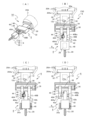
- FIG. 1 is a perspective view showing a robot device according to a first embodiment
- FIG. (A) is a perspective view showing the composite robot hand of the first embodiment
- (B), (C), and (D) are respectively partial front views showing the composite robot hand in cross section.
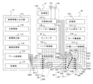
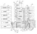
- Fig. 3 shows three controllers of the first embodiment
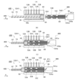
- (A), (B), and (C) are cross-sectional views showing one terminal of the first connector and one corresponding terminal of the second connector, respectively
- FIG. 4 is a perspective view showing two contacts and a third contact of a second connector
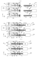
- 4A, 4B, and 4C are cross-sectional views showing three terminals of a first connector and three corresponding terminals of a second connector, respectively;
- FIG. 4 is a flow chart showing an example of a connection method
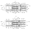
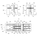
- (A) and (B) are sectional views showing a first connector and a second connector, respectively, of a second embodiment.
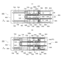
- (A) and (B) are cross-sectional views showing states in which the first connector and the second connector are connected, respectively.
- (A) and (B) are cross-sectional views showing a state in which the first connector and the second connector are disconnected after being connected, respectively.
- (A), (B), and (C) are cross-sectional views respectively showing a first connector and a second connector of a first modified example.
- FIG. 3 shows three controllers of a third embodiment
- FIG. 1 shows a robot device 2 of this embodiment.
- the X-axis and the Y-axis which are parallel and orthogonal to the installation surface of the robot device 2 are taken, and the Z-axis is taken perpendicular to the installation surface.
- the installation surface is substantially horizontal, and the upper side of the installation surface (opposite direction to the vertical direction) is the + direction of the Z axis.
- a robot apparatus 2 includes a robot body 4, a robot hand (hereinafter referred to as a two-finger gripper) 6 having two movable fingers 40A and 40B joined to the robot body 4; An attached small robot hand (hereinafter referred to as a finger attachment) 8 that is gripped by the finger portions 40A and 40B of the finger gripper 6 is provided. Further, the robot device 2 includes a control device 10 that controls the operation of the robot main body 4, a control device 12 that controls the operation of the two-finger gripper 6, and a control device 26 that controls the operation of the finger attachment 8. ing.
- the robot main body 4 includes a base portion BP, and a first robot arm 18A, a second robot arm 18B, and a third robot arm 18C that are displaceably connected to the base portion BP in order.
- a two-finger gripper 6 is joined to the tip 20A of the third robot arm 18C.
- the two-finger gripper 6 can also be called the parent hand or end effector, and the finger attachment 8 can also be called the child hand.
- the first robot arm 18A can control the rotation angle ⁇ 1 and the turning angle ⁇ 1
- the second robot arm 18B can control the rotation angle ⁇ 2 and the turning angle ⁇ 2
- the third robot arm 18B can control the rotation angle ⁇ 1 and the turning angle ⁇ 2.
- 18C can control the rotation angle ⁇ 3 and the turning angle ⁇ 3.
- the third robot arm 18C has a rotating portion 20B that changes the rotation angle ⁇ 3 of the distal end portion 20A and an inclination driving portion 20C that changes the turning angle ⁇ 3.
- the rotating portion 20B and the tilt driving portion 20C each have a driving motor and an encoder for detecting the rotation angle.
- the other robot arms 18A, 18B have similar drives.
- the two-fingered gripper 6, which is joined to the third robot arm 18C has six degrees of freedom of position (including angles), including positions in the X, Y, and Z directions, and angles of rotation about three axes. is controllable.
- the finger attachment 8 gripped by the two-finger gripper 6 of this embodiment has an electric drill 28 as an example.
- the two-finger gripper 6 and the finger attachment 8 are detachably electrically connected via a connecting device 44 (see FIG. 2(A)).
- a connecting device 44 see FIG. 2(A)
- various materials can be drilled.
- the structure in which the two-finger gripper 6 and the finger attachment 8 are connected via the connecting device 44 will be referred to as a composite robot hand 14.
- a finger attachment 8C having two small fingers 28C (not shown) that can grasp a , and a finger attachment (not shown) having, for example, an L-shaped hook are stored.
- the finger attachment 8 it is possible to use one having any other configuration and capable of performing any work.
- the robot arms 18A to 18C are driven to return the finger attachment 8 gripped by the two-finger gripper 6 at the tip of the robot arm 18C to the base 24a, and any of the other finger attachments 8A to 8C, etc. It can also be gripped with a finger gripper 6 .
- a structure in which the two-finger gripper 6 and the finger attachments 8A to 8C and the like are connected by a connecting device (not shown) similar to the connecting device 44 can also be regarded as a composite robot hand.
- the finger attachment 8 gripped by the two-finger gripper 6 is returned to the storage unit 24, the robot arms 18A to 18C are driven to return the two-finger gripper 6 at the tip of the robot arm 18C to the stage 22,
- Other robot hands such as the robot hands 6A and 6B can also be joined to the tip of the robot arm 18C.
- the two-finger gripper 6 is joined to the tip of the robot arm 18C and the two-finger gripper 6 grips the finger attachment 8.
- the robot device 2 also includes an imaging device (not shown).
- the imaging device can be provided at an arbitrary position such as one surface of the two-finger gripper 6, the tip 20A of the robot arm 18C, the imaging position on the installation surface of the robot device 2, or the wall of the room.
- the robot device 2 is of a vertical articulated type, the configuration of the robot device 2 is not limited to the configuration shown in FIG.
- a robot device having an arbitrary configuration such as another horizontal multi-joint type (scalar type) or parallel link type can be used.
- FIG. 2(A) shows the composite robot hand 14 in FIG. 1
- FIGS. 2(B) to 2(D) show a part of the composite robot hand 14 in sectional view.
- the composite robot hand 14 has a two-finger gripper 6 , a finger attachment 8 , and a connection device 44 that electrically connects the finger attachment 8 to the two-finger gripper 6 .
- the connecting device 44 is configured by connecting a first connector 46 provided on the two-finger gripper 6 to a second connector 48 provided on the finger attachment 8 .
- the two-finger gripper 6 includes a joint 30 (joint) joined to the tip 20A of the robot arm 18C, a main body 32 fixed to the joint 30, and two grippers movable with respect to the main body 32. It has finger portions 40A and 40B and a control device 12 .
- the direction in which the finger portions 40A and 40B open and close is defined as the X axis (see FIG. 2B), and the direction parallel to the X axis is defined as the X direction.
- the joint portion 30 is fixed to the tip portion 20A by, for example, a movable pawl mechanism 20Aa (see FIG. 2(B)).
- the joining method of the joining portion 30 may be other mechanical methods (fixing with screws, fixing with leaf springs, etc.) or electrical methods (fixing with electromagnets, etc.).
- the joint portion 30 is provided with a connection portion 30a (see FIG. 2B) for electrical wiring, compressed air piping, and/or vacuum adsorption piping, etc., as required.
- the joining portion 30 is provided with positioning portions (not shown) such as a plurality of protrusions or recesses so that the position and the rotation angle with respect to the tip portion 20A have predetermined values.
- the finger attachment 8 includes a gripped portion 42 gripped by the finger portions 40A and 40B of the two-finger gripper 6, a body portion 40 fixed to the gripped portion 42, and a motor (not shown) in the body portion 40. ) and a control device 26 .
- a drive shaft 38 parallel to the X direction in the main body 32 of the two-finger gripper 6, there are a drive shaft 38 parallel to the X direction, a motor 34 for rotating the drive shaft 38, and a rotation angle of the motor 34.
- An encoder 36 for example a rotary encoder, and two finger portions 40A and 40B screwed onto a drive shaft 38 are provided.
- the right and left halves of the drive shaft 38 are formed with right-hand threads 38a and left-hand threads 38b, respectively.
- the finger portions 40A and 40B can be moved in the opposite directions along the X direction to open and close the finger portions 40A and 40B.
- the control device 12 obtains the interval (or position) between the finger portions 40A and 40B from the detection value of the encoder 36, and drives the motor 34 based on this interval, thereby controlling the interval (or position) between the finger portions 40A and 40B. ) can be controlled.
- the configuration of the drive mechanism for the finger portions 40A and 40B is arbitrary, and for example, the finger portions 40A and 40B may be individually driven in the X direction using different motors.
- Positioning concave portions 40Aa and 40Ba are provided inside the finger portions 40A and 40B, respectively, and corresponding convex portions 42a and 42b are provided on two side surfaces of the gripped portion 42 of the finger attachment 8 in the X direction. It is Further, a first connector 46 is provided on the +X direction inner surface of the finger portion 40A on the -X direction side of the two-finger gripper 6, and a second connector 48 is provided on the -X direction side surface of the gripped portion 42 of the finger attachment 8. is provided.
- the protrusions 42a and 42b of the gripped portion 42 are engaged with the recessed portions 40Aa and 40Ba of the finger portions 40A and 40B, whereby the first connector 46 and the second connector 46 are connected. 2 connector 48, and the finger attachment 8 can be stably gripped by the finger portions 40A and 40B.
- the main body portion 32 of the two-finger gripper 6 is provided with the control device 12
- the main body portion 40 of the finger attachment 8 is provided with the control device 26 .
- the control device 12 and the control device 26 may be provided at separate locations (for example, in a server outside the robot device 2).
- FIG. 3 shows the control device 10 of the robotic device 2, the control device 12 of the two-finger gripper 6, the control device 26 of the finger attachment 8 and the connection device 44 of this embodiment.
- the control device 10 controls the control information input/output unit 11A for inputting/outputting control information (the type of finger attachment to be used, the position to be processed, etc.) with the operator, for example, and the two-finger gripper 6.
- a main control unit 11B that transmits and receives control information between the device 12 and the control device 26 of the finger attachment 8 and controls the operation of the entire device, and at least six axes that detect the movements of the robot arms 18A to 18C.
- a coordinate calculation unit 11C that processes the detection result of the encoder and calculates the coordinates and rotation angle of the tip of the finger attachment 8 (electric drill 28) held by the two-finger gripper 6 at the tip of the third robot arm 18C.
- control device 10 processes the imaging signal of an imaging device (not shown) and obtains the positional relationship between, for example, the tip of the finger attachment 8 held by the two-finger gripper 6 and the object.
- 11D an arm control section 11E for controlling movements of the robot arms 18A to 18C based on the processing results of the coordinate calculation section 11C and the image processing section 11D, and a storage section 11F.
- the storage unit 11F may include, for example, a storage device such as a HDD (Hard Disk Drive) or an SSD (Solid State Drive), or a non-volatile memory such as a USB (Universal Serial Bus memory).
- the storage unit 11F stores a program of the control device 10, various setting values, and the like.
- the arm controller 11E also controls the operation of the controller 12 of the two-finger gripper 6 and the controller 26 of the finger attachment 8 under the control of the main controller 11B.
- the control device 12 of the two-finger gripper 6 includes a hand control section 13A that controls the operation of the entire device, an encoder 36 shown in FIG. It has a drive section 13B, a state detection section 13C for detecting a state such as an electrical abnormality on the finger attachment 8 side, and a storage section 13D.
- the storage unit 13D has the same configuration as the storage unit 11F, and stores programs for the control device 12 and various setting values.
- a buzzer 12a and a light emitting part 12b e.g., a light emitting diode
- FIG. 2B is connected to the state detecting part 13C for informing the operator or the like of alarm information such as an abnormality on the finger attachment 8 side.
- the buzzer 12a or the light emitting section 12b may be provided.
- the arm control unit 11E of the control device 10 and the hand control unit 13A of the control device 12 are connected to a ground line GND, which is grounded, and a low voltage (for example, 3.3V or 5V) for driving electronic circuits.
- the ground line GND to the data line DA2 on the arm control unit 11E side are connected to the corresponding terminals of the first connector 56a, and the ground line GND to the data line DA2 on the hand control unit 13A side are connected to the second connector 56b.
- a second connector 56b is connected to the first connector 56a.
- a connection device 56 is configured to connect the control device 12 (two-finger gripper 6) to the arm control section 11E (control device 10) from the first connector 56a and the second connector 56b.
- the ground line GND, the low voltage line DC1, the high voltage line DC2, and the control line CN extend from the arm control section 11E to the control device 26 side of the finger attachment 8 as well.
- the data lines DA1 and DA2 extend from the hand control section 13A to the control device 26 side.
- the data lines DA1 and DA2 connect the arm controller 11E, the hand controller 13A, and the controller 26 in a daisy chain manner, for example.
- the EtherCAT registered trademark
- the arm control section 11E becomes the master
- the hand control section 13A and the attached hand control section 27A become slaves.
- the controllers (not shown) of the robot arms 18C to 18C in FIG. 1 are slaves connected between the arm controller 11E and the hand controller 13A in a daisy chain manner.
- a daisy chain method standards such as EtherNet/IP (registered trademark) or IEEE 1394 can also be used.
- the data lines DA1 and DA2 can also be connected by a system other than the daisy chain system (for example, star connection).
- the control device 26 of the finger attachment 8 includes an attached hand control section 27A that controls the operation of the entire device, a drill motor 27C, and a motor drive section 27B that drives the electric drill 28 via the drill motor 27C. , and a storage unit 27D.
- the storage unit 27D has the same configuration as the storage unit 11F, and stores programs for the control device 26 and various set values.
- the control device 12 and the control device 26 are electrically connected by a connection device 44 .
- the first connector 46 of the connecting device 44 is a female connector and the second connector 48 is a male connector.
- the first connector 46 may be a male connector and the second connector 48 may be a female connector.
- the ground line GND, the low voltage line DC1, the high voltage line DC2, and the control line CN that have passed through the control device 12 are connected to the terminals 52F, 52E, 52D, and 52C of the first connector 46 of the connection device 44.
- the data lines DA1 and DA2 connected to the first contact 53A and extending from the hand control section 13A are connected to the first contacts 53A of the terminals 52B and 52A of the first connector 46, respectively.
- the finger attachment 8 when attaching and detaching the finger attachment 8 to and from the two-finger gripper 6, the finger attachment 8 is connected to the corresponding signal lines DA2 to GND to the first contacts 53A of the terminals 52A to 52F of the first connector 46.
- connection using the connection device 44 is performed, for example, by the hot connect (hot plug) or hot-swap method defined in EtherCAT (registered trademark).
- EtherCAT registered trademark
- erroneous data or the like may be supplied to the data line DA1 or the like.
- an error may occur in which erroneous data or the like is supplied from the control device 12 or the control device 26 to the arm control section 11E.
- the terminals 52A to 52F of the first connector 46 each have a second contact 53B in this embodiment.
- a state detection signal (described later) is supplied from the state detection section 13C to the second contacts 53B of the terminals 52A to 52F.
- Supplying a signal to the second contact 53B also includes detecting a signal (voltage) generated at the second contact 53B on the state detection unit 13C side.
- the data lines DA2 and DA1, the control line CN, the high voltage line DC2, the low voltage line DC1, and the ground line GND connected to the attached hand control section 27A of the control device 26 are connected to the terminal 54A of the second connector 48, respectively. , 54B, 54C, 54D, 54E and 54F.
- the second connector 48 when connecting the second connector 48 to the first connector 46, the second connector 48 is pushed into the first connector 46 by a predetermined amount, and then the third terminals 54A to 54F of the second connector 48 are connected.
- the contacts 55 are first connected to the second contacts 53B of the corresponding terminals 52A-52F of the first connector 46. As shown in FIG.
- connection device 44 does not necessarily have to be used in a hot-swap system.
- the X-axis is taken along the direction in which the interval between the terminals 52A and 54A changes
- the Y-axis is taken along the direction orthogonal to the X-axis in the plane of FIG. 4A.
- the terminal 52A has an elongated hole portion 58a (guide portion) extending in the X direction (direction parallel to the X axis) provided in an insulating case 58, and an inner surface of the hole portion 58a extending in the X direction. It has a first contact 53A and a second contact 53B provided at predetermined intervals along it. The first contact 53A and the second contact 53B are made of a conductive material (eg, metal). Further, the terminal 52A includes a flexible ring-shaped waterproof seal 64 fixed to the tip of the hole 58a in the +X direction, and an insulative columnar seal 64 arranged in the hole 58a so as to be movable in the X direction.
- a flexible ring-shaped waterproof seal 64 fixed to the tip of the hole 58a in the +X direction
- an insulative columnar seal 64 arranged in the hole 58a so as to be movable in the X direction.
- the waterproof seal 64 is, for example, an O-ring. Any other elastic member can be used instead of the compression coil spring 62 .
- the first contact 53A is connected to the data line DA2 extending from the hand control section 13A in FIG. 3 via a signal line 53Aa extending in the Y direction, and the second contact 53B is connected via a signal line 53Ba extending in the Y direction. It is connected to the detector 13C.
- the terminal 54A includes a cylindrical insulator 68 (engagement portion) elongated in the X direction and protruding from the insulating case 66 in the -X direction, and a short circle provided at the tip of the insulator 68 in the -X direction. It has a columnar third contact 55 and a signal line 55 a connected to the third contact 55 through the center of the insulator 68 .
- the insulator 68 may actually be an insulating coating formed around the signal line 55a.
- the third contact 55 is made of a conductive material (eg, metal). The outer diameters (diameters) of the third contact 55 and insulator 68 are substantially the same.
- the outer diameters of the cap 60 and the third contact 55 are set slightly smaller than the inner diameter of the hole 58a. Also, the inner diameter of the waterproof seal 64 is set slightly smaller than the outer diameters of the cap 60 and the third contact 55 .
- the signal line 55a is connected via a signal line in the case 66 to a data line DA2 extending from the attached hand control section 27A in FIG.
- the first contact 53A and the second contact 53B of the present embodiment are ring-shaped conductive (for example, made of metal) arranged in a concave portion on the inner surface of the hole portion 58a.
- the inner diameter of the coil spring CS is set slightly smaller than the outer diameter of the third contact 55, and when the terminal 54A is inserted into the terminal 52A side, almost the entire circumference of the coil spring CS contacts the third contact 55.
- the coil springs CS (contacts 53A, 53B) are electrically stably connected to the third contacts 55, respectively.
- the third contact 55 can easily move relative to the coil spring CS in the X direction.
- the first contact 53A and the second contact 53B may be configured arbitrarily.
- the contacts 53A and 53B may be made of a conductive plate spring or the like.
- the two-fingered gripper grips the gripped portion 42 of the finger attachment 8 mounted on the base 24a of the storage unit 24 of FIG. 6 shows a state in which finger portions 40A and 40B of No. 6 are moved.
- the cap 60 of the terminal 52A is stationary within the waterproof seal 64 at the tip of the hole 58a due to the frictional force between the cap 60 and the waterproof seal 64.
- FIG. Therefore, for example, even if water is sprinkled outside the first connector 46, water droplets or the like can be prevented from entering the hole portion 58a.
- the third contact 55 of the terminal 54A is It is inserted into the hole 58a of the terminal 52A.
- the finger portions 40A and 40A of the two-finger gripper 6 are connected.
- the distance of 40B in the X direction is fixed, and the state in which the third contact 55 is in contact with the second contact 53B is maintained.
- the hand control unit 13A of the two-finger gripper 6 in FIG. 3 can recognize the distance between the finger portions 40A and 40B in the X direction and the state where the third contact 55 is connected to the second contact 53B from the detection value of the encoder 36.
- the distance between the finger portions 40A and 40B is narrowed, and as shown in FIG. is fixed, the distance between the finger portions 40A and 40B is fixed.
- the third contact 55 of the terminal 54A is connected to the first contact 53A of the terminal 52A.
- the hand control unit 13A of the two-finger gripper 6 can recognize the state in which the third contact 55 is connected to the first contact 53A from the distance in the X direction between the finger portions 40A and 40B obtained from the detection value of the encoder 36.
- the state in which the third contact 55 is connected (contacted) to the first contact 53A is referred to as the terminal 54A and the terminal 52A being at the first relative position P1 in the X direction, and the third contact 55 is the first contact.
- the state in which the two contacts 53B are connected (contacted) is said to be the second relative position P2 between the terminals 54A and 52A in the X direction.
- the configurations of the other terminals 52B to 52F and 54B to 54F in FIG. 3 are similar to the configuration of the terminals 52A and 54A.
- the state detecting section 13C sends a detection signal to the second contacts 53B of the terminals 52A to 52C. No need to supply.
- the two-finger gripper 6 and the finger attachment 8 of this embodiment are placed in a rainy environment, water droplets RD adhere to the terminals 54A, 54B, etc. of the second connector 48 of the finger attachment 8. There is a fear that
- the terminals 54A to 54C of the second connector 48 are set at the second relative position P2 with respect to the terminals 52A to 52C of the first connector 46, and the terminals 54A to 54C are connected. are connected to the second contacts 53B of the terminals 52A to 52C, the state detector 13C detects the first connector 46 (two-finger gripper 6) and the second connector 48 (finger attachment 8). ) to detect whether or not there is an abnormality in at least one side. As an example, assume that the anomaly is a short between terminals 52A-52C and/or between terminals 54A-54C.
- the terminals 52A to 52C are provided with the waterproof seal 64, if the function of the waterproof seal 64 is perfect, the water droplets RD on the terminals 54A and 54B enter the hole 58a of the case 58 of the first connector 46. do not. However, when the waterproof seal 64 wears or deteriorates, or when the terminals 54A to 54C are inserted into the first connector 46 through the waterproof seal 64, the waterproof seal 64 does not function as desired when foreign matter gets caught in the inner surface of the waterproof seal 64. Otherwise, part of the water droplet RD may enter the hole 58 a of the case 58 .
- a short circuit between the terminals 52A to 52C on the first connector 46 side and/or a short circuit between the terminals 54A to 54C on the second connector 48A side may occur within the case 58 . If such a short circuit occurs, the control command cannot be accurately supplied from the arm control section 11E of FIG. 3 to the attached hand control section 27A of the finger attachment 8 via the data line DA1. Furthermore, it is not possible to accurately output response information or the like from the attached hand control section 27A to the arm control section 11E via the data line DA2.
- such a Detects the presence or absence of a short circuit.
- the state detection unit 13C first applies a level (hereinafter referred to as a A high level) signal S1 is supplied, and the signals U1 and U2 generated at the second contacts 53B of the other terminals 52B and 52C are detected.
- the signals U1 and U2 generated at the second contacts 53B of the terminals 52B and 52C are at 0 level (ground level).
- the state detection section 13C can determine that there is no short circuit between the terminal 54A and the terminals 54B and 54C.
- the signals U1 and U2 generated at the second contacts 53B of the terminals 52B and 52C are at high level, respectively. Therefore, if at least one of the signals U1 and U2 is at high level, the state detector 13C can determine that there is a short circuit between the terminal 54A and the terminals 54B and 54C (or one of them).
- the state detection unit 13C When it is determined that there is a short circuit, the state detection unit 13C generates an alarm sound from the buzzer 13a, flashes the light emitting unit 12b, and outputs information indicating that a short circuit has occurred to the hand control unit 13A.
- the hand control section 13A causes the finger attachment 8 to detach from the two-finger gripper 6 .
- the second connector 48 is disconnected from the first connector 46 .
- An operator or the like can take measures such as removing water droplets from the terminals 54A to 54C of the second connector 48 in response to the alarm sound or flashing light. Note that alarm information may be output using either the buzzer 13a or the light emitting unit 12b.
- the hand control unit 13A causes a short circuit in the arm control unit 11E (main control unit 11B) on at least one of the first connector 46 (two-finger gripper 6) side and the second connector 48 (finger attachment 8) side. provide information indicating that Thereafter, as an example, an operator or the like inputs control information to the main control section 11B (arm control section 11E) via the control information input/output section 11A, indicating that the cause of the short circuit has been removed and the finger attachment 8 can be gripped again. be.
- the arm controller 11E sends a control command to the hand controller 13A to grip the finger attachment 8 again.
- the two-finger gripper 6 performs the action of gripping the finger attachment 8 again.
- the state detection unit 13C detects the short circuit of the terminal 52B.
- a high level signal S1 is supplied to the second contact 53B, and the signal generated at the second contact 53B of the other terminal 52C is detected. If the signal generated at the second contact 53B of the terminal 52C is high level, it can be determined that there is a short circuit between the terminals 54B and 54C. It can be determined that there is no short circuit between 54B and 54C.
- the presence or absence of a short circuit between all terminals 54A to 54F (and between all terminals 52A to 52F) can be detected.
- an abnormality for example, disconnection of the signal line 55a extending from the third contact 55 of the terminals 54A to 54F, or an abnormality in the operation of the electronic circuit in the control device 26 can be detected.
- detecting disconnection of the signal line for example, a period of supplying a high level signal to the second contact 53B of the terminal 52E corresponding to the low voltage line DC1 and a period of supplying a 0 level signal to the second contact 53B of the terminal 52E.
- the signals generated at the second contacts 53B of the terminals 52A to 52C may be detected continuously during the period of supplying the signals.
- the signal generated at the second contact 53B of the terminal 52B is continuously at 0 level, it may be determined that the signal line extending from the third contact 55 of the corresponding terminal 54B is broken. On the other hand, if the signal generated at the second contact 53B of the terminal 52B is at some level between 0 level and high level, it means that the signal line extending from the third contact 55 of the corresponding terminal 54B is not disconnected. You can judge.
- the terminals 54A to 54C of the second connector 48 are set to the first relative position P1 with respect to the terminals 52A to 52C of the first connector 46, and the third contacts 55 of the terminals 54A to 54C are set to the first positions of the terminals 52A to 52C, respectively.
- finger attachments 8 are attached to the third contacts 55 of the terminals 54A to 54C (and 54D to 54F) of the second connector 48 via the first contacts 53A of the terminals 52A to 52C (and 52D to 52F). is supplied with a signal or voltage ready for use.
- the terminals 54A to 64C are separated from the terminals 52A to 52C as shown in FIG. 5(A). be.
- the caps 60 of the terminals 52A to 52C are pushed back toward the tip of the case 58 in the +X direction by the coil springs 62, and the caps 60 stop inside the waterproof seals 64.
- FIG. As a result, external water droplets or the like can be prevented from entering the case 58 .
- the following operations are controlled by the arm control section 11E under the control of the main control section 11B of the control device 10 of the robot device 2.
- the two-finger gripper 6 is joined to the robot arm 18C of the robot device 2 in FIG. 1, and nothing is gripped between the fingers 40A and 40B of the two-finger gripper 6.
- the finger attachment 8 is held on the pedestal 24a of the storage section 24 of FIG.
- the finger attachment 8 is used for the first contacts 53A of the terminals 52A to 52F of the first connector 46 on the two-finger gripper 6 side in order to perform hot connection. start supplying the same signal or voltage as in the current state.
- the robot arms 18A to 18C of the robot device 2 are driven to move the two-finger gripper 6 at the tip 20A of the robot arm 18C to the holding position of the finger attachment 8 in the storage section 24.
- the distance between the finger portions 40A and 40B of the two-finger gripper 6 is narrowed, and the gripped portion 42 of the finger attachment 8 is started to be held.
- the hand control section 13A of the two-finger gripper 6 takes in the detected value of the encoder 36 at a predetermined sampling rate, and the second connector 48 is at the second relative position P2 with respect to the first connector 46. ie, whether the third contacts 55 of the terminals 54A to 54F of the second connector 48 are connected to the second contacts 53B of the terminals 52A to 52F of the first connector 46.
- the process proceeds to step 110, the hand control section 13A maintains the distance between the finger sections 40A and 40B, and the state detection section 13C detects whether or not there is an abnormality. Let it be detected.
- the state detection unit 13C supplies a state detection signal to the second contacts 53B of the terminals 52A to 52F of the first connector 46 as described above, and the terminals 52A to 52F and the terminals 52A to 52F of the first connector 46 Whether or not the terminals 54A to 54F of the second connector 48 are short-circuited is detected.
- step 112 if it is determined that there is no short circuit on all sides of the terminals 52A to 52F and the terminals 54A to 54F, the operation proceeds to step 114, and the state detection section 13C sends the hand control section 13A to the second Information indicating that there is no abnormality on the connector 48 (finger attachment 8) side is output. Accordingly, the hand control section 13A narrows the distance between the finger sections 40A and 40B, and sets the second connector 48 to the first relative position P1 with respect to the first connector 46. As shown in FIG. In this state, the distance between finger portions 40A and 40B is fixed.
- the finger attachment 8 is stably gripped by the finger portions 40A and 40B of the two-finger gripper 6, and the third contacts 55 of the terminals 54A to 54F of the second connector 48 are the third contacts of the terminals 52A to 52F of the first connector 46. 1 contact 53A, and a signal or voltage is supplied to the attached hand control section 27A of the finger attachment 8 via the arm control section 11E and the hand control section 13A. Information indicating that the two-finger gripper 6 has reliably gripped the finger attachment 8 is output from the hand control section 13A to the arm control section 11E.
- the arm control unit 11E drives the robot arms 18A to 18C to move the composite robot hand 14 to the working position, and the attached hand control unit 27A of the finger attachment 8 operates the electric drill 28. send control information to By driving the electric drill 28 by the attached hand control unit 27A, work such as drilling is performed at the work position.
- step 112 if it is determined in step 112 that at least some of the terminals 54A to 54F are short-circuited, the operation proceeds to step 118, and the state detection unit 13C detects the buzzer 12a and the light emitting unit 12b (or one of them). is used to indicate information indicating that an abnormality (short circuit) has occurred on the second connector 48 (finger attachment 8) side. This information is also transmitted to the hand control section 13A. Then, in step 120, the hand control section 13A opens the gap between the finger sections 40A and 40B, and separates the finger attachment 8 from the two-finger gripper 6 as shown in FIG. 2(D).
- step 122 the operator removes water droplets RD adhering to the terminals 54A to 54F of the second connector 48 of the finger attachment 8, and the like.
- a blower (not shown) is provided in the main body 32 of the two-finger gripper 6, and air is blown from the sending unit toward the second connector 48 to automatically remove the water droplets RD. good too.
- the operator inputs information indicating that the cause of the abnormality on the finger attachment 8 side has been eliminated to the control information input/output unit 11A in FIG.
- the operation returns to step 106, and the arm controller 11E sends to the hand controller 13A information indicating that the two-finger gripper 6 will grip the finger attachment 8.
- gripping of the finger attachment 8 by the two-finger gripper 6 (connection of the connecting device 44) is started. For example, if it is determined that there is a short circuit in step 112 even after performing the operations of steps 106 to 122 a predetermined number of times, the operator may replace the finger attachment 8, for example.
- An abnormality detection signal may be supplied from the state detection unit 13C to the second contacts 53B of the terminals 52A to 52F of the first connector 46 to detect whether there is a short circuit between the terminals 52A to 52F of the first connector 46. .
- a dummy terminal made of a water absorbing material is inserted into the case 58 of the first connector 46 to of water may be removed.
- the second contacts 53B of the terminals 52A to 52F of the first connector 46 are located at the installation position of the waterproof seal 64 of the case 58 or the outlet of the hole portion 58a (a portion where water droplets are highly likely to enter) compared to the first contact 53A. ) is located close to Therefore, the presence or absence of a short circuit can be detected using the second contact 53B before a short circuit occurs with respect to the first contact 53A.
- the terminals 52A to 52F of the first connector 46 on the two-finger gripper 6 side have the first contact 53A for driving and the second contact 53B for confirming abnormality. is provided. Then, when the third contact 55 of the terminals 54A to 54F of the second connector 48 on the finger attachment 8 side is connected to the second contact 53B, an abnormality confirmation signal is supplied to the second contact 53B to The presence or absence of abnormality on the connector 48 side is detected.
- the connecting device 44 of the present embodiment is provided on the finger attachment 8 (second device) side with respect to the first connector 46 (first connecting portion) provided on the two-finger gripper 6 (first device) side. It is a connection device that electrically connects the finger attachment 8 to the two-finger gripper 6 by connecting a second connector 48 (second connection portion) provided in the .
- one first connector 46 has a terminal 52A (first terminal) having a first contact 53A and a second contact 53B located at different positions along the X direction (first direction).
- the second connector 48 can be mechanically connected to the terminal 53A by moving relative to the first terminal 53A along the X direction, and has a terminal 54A (second terminal) having a third contact 55 , and when the terminals 53A and 54A are set at first and second relative positions P1 and P2 that are different from each other along the X direction, the third contact 55 becomes the first contact 53A and the second contact 53B, respectively. is electrically connected to the
- the composite robot hand 14 (robot hand device) of the present embodiment is capable of being joined to the robot arm 18C and is held by the two-finger gripper 6 (hand section) joinable to the robot arm 18C and the two-finger gripper 6.
- a possible finger attachment 8 (accessory hand part)
- a connector 46 is provided on the two-finger gripper 6 side
- a second connector 48 having terminals 54A is provided on the finger attachment 8 side.
- the robot apparatus 2 of the present embodiment includes the composite robot hand 14, the robot arm 18C to which the composite robot hand 14 is joined, and the driving units (robot arms 18A and 18B, rotating unit 20B and tilting unit 20B) that drive the robot arm 18C. and a drive unit 20C).
- the first contact 53A of the terminal 52A of the first connector 46 is supplied with the same signal or voltage as when the finger attachment 8 is connected.
- the third contact 55 of the terminal 54A of the second connector 48 is connected to the second contact 53B of the terminal 52A of the first connector 46, by supplying a state confirmation signal to the second contact 53B, An abnormality such as an electrical short circuit on the second connector 48 (finger attachment 8) side can be detected.
- the finger attachment 8 By connecting the third contact 55 to the first contact 53A of the first connector 46 when there is no electrical abnormality, the finger attachment 8 can be operated as it is. Therefore, the connecting device 44 can be safely used for hot-connecting, and the finger attachment 8 can be electrically connected to the two-finger gripper 6 safely and quickly.
- the two-finger gripper 6 is connected by connecting the second connector 48 provided on the finger attachment 8 side to the first connector 46 provided on the two-finger gripper 6 side. It is a connection method for electrically connecting the finger attachment 8 with the finger attachment.
- connection method is such that when the terminal 52A and the second terminal 54A are set at the second relative position P2 along the X direction and the third contact 55 is electrically connected to the second contact 53B, the A step 110 of supplying a predetermined signal to the two contacts 53B to detect whether there is an electrical abnormality in the finger attachment 8 (second connector 48); a step 114 of electrically connecting the third contact 55 to the first contact 53A by setting the terminals 52A and 54A to a first relative position P1 along the X direction when there is no .
- the same signal or voltage is supplied to the first contact 53A of the terminal 52A of the first connector 46 as when the finger attachment 8 is connected. Then, when the third contact 55 of the terminal 54A of the second connector 48 is connected to the second contact 53B of the terminal 52A and there is no abnormality on the second connector 48 side, the third contact 55 is connected to the first contact 53A.
- the finger attachment 8 can be operated as it is. Therefore, the finger attachment 8 can be electrically connected to the two-finger gripper 6 safely and quickly.
- the second connector 48 may be provided on the two-finger gripper 6 side, and the first connector 46 may be provided on the finger attachment 8 side.
- the finger attachment 8 (attached hand control unit 27A) side can detect whether there is an electrical abnormality on the two-finger gripper 6 (second connector 48) side.
- the second connector 48 is provided on the two-finger gripper 6 side and the first connector 46 is provided on the finger attachment 8 side, in FIG.
- the second contact 53B may be provided, and the third contact 55 may be provided in the hole portion 58a of the terminal 52A.
- all the terminals 52A to 52F of the first connector 46 are provided with the first contacts 53A and the second contacts 53B, all the terminals 54A to 54F of the second connector 48 can be prevented from malfunctioning. Presence or absence can be detected.
- only the terminals 52D to 52F to which the ground line GND, the low voltage line DC1, and the high voltage line DC2 are connected are provided with the first contact 53A and the second contact 53B, and the other terminals 52A to 52C are provided with Only the first contact 53A may be provided.
- connection device 44 since the connection device 44 is used in a hot-swap system, the finger attachment 8 can be operated immediately after the two-finger gripper 6 grips the finger attachment 8 .
- the connection device 44 does not necessarily have to be used in a hot-swap system.
- the connection device 44 is not used for hot-swapping, for example, in step 112 of FIG. are connected to the first contacts 53A of the terminals 52A to 52F of the first connector 46, the ground line GND, the low voltage line DC1, and the high voltage line DC2 are connected to the ground level and the low voltage line, respectively, in the arm control section 11E of FIG. , and high voltage.
- FIGS. 7(A) to 9(B) A second embodiment will be described with reference to FIGS. 7(A) to 9(B). 7(A) to 9(B), parts corresponding to FIGS. 4(A) to (D) and FIGS. 5(A) to (C) are denoted by the same or similar reference numerals. A detailed description thereof is omitted.
- the connecting device 44A of this embodiment is also used to electrically connect the finger attachment 8 to the two-finger gripper 6 in the composite robot hand 14 of FIG.
- the connecting device 44A comprises a first connector 46A provided on the two-finger gripper 6 and a second connector 48A provided on the finger attachment 8.
- the first connector 46A is a female connector and the second connector 48A is a male connector. That is, the first connector 46A includes a first case 58A and a second case 58B connected in the X direction, a buffer member 58C arranged movably in the X direction in the first case 58A, and a shock absorber 58C in the second case 58B.
- Insulating rod-shaped members 72A and 72B elongated in the X direction are arranged movably in the X direction in the two holes 58Bc and 58Bd in which the first contact 53A and the second contact 53B are arranged.
- a buffer member 58C is fixed to the -X direction end of 72B.
- the buffer member 58C is movable within the first case 58A along two guide shafts 74A and 74B parallel to the X-axis, and is movable within the first case 58A so as to surround the guide shafts 74A and 74B.
- Compression coil springs 76A and 76B are provided to bias in the +X direction. It should be noted that the compression coil springs 76A.
- a permanent magnet 78A (magnetic member) is provided in the center of the buffer member 58C.
- the second case 58B is made of a ferromagnetic material (such as iron), and the permanent magnet 78A attracts the buffer member 58C toward the second case 58B.
- An insulating coating is formed on the inner surfaces of the central holes 58Bc and 58Bd of the second case 58B.
- ring-shaped waterproof seals 64A and 64B are provided at the +X direction ends of the inner surfaces of the hole portions 58Bc and 58Bd of the second case 58B, and two guide holes are formed in the peripheral portion of the second case 58B parallel to the X axis. 58Ba and 58Bb (additional guide portions) are provided, and a ring-shaped waterproof seal 64C is installed inside the guide holes 58Ba and 58Bb at the ends of the second case 58B in the +X direction.
- waterproof seals 64A and 64B are small O-rings, and waterproof seal 64C is a large O-ring.
- the second connector 48A includes a disc-shaped first case 66A, a disc-shaped second case 66B disposed on the -X direction side of the first case 66A so as to be relatively movable in the X direction, and a first A first terminal 54A and a second terminal 54B are provided in the central portion of the case 66A so as to protrude in the -X direction, and two positioning pins 80A are provided in parallel with the terminals 54A and 54B in the peripheral portion of the first case 66A. , 80B (moving portion), and compression coil springs 82A, 82B provided around the positioning pins 80A, 80B to bias the second case 66B in the -X direction with respect to the first case 66A.
- the terminals 54A and 54B are each fixed to the first case 66A and elongated in the X direction with a cylindrical insulator 68, a conductive third contact 55 provided at the tip of the insulator 68 in the -X direction, and the insulator. 68 and a signal line 55 a connected to the third contact 55 .
- the tips of the terminals 54A and 54B and the tips of the positioning pins 80A and 80B are respectively inserted through corresponding openings provided in the second case 66B.
- the positioning pins 80A and 80B of the second connector 48A can be accommodated in the guide holes 58Ba and 58Bb provided in the second case 58B of the first connector 46A.
- a ring-shaped waterproof seal 64D is provided on the second case 66B so as to cover the outer surfaces of the terminals 54A and 54B, and is located at the peripheral edge of the second case 66B facing the waterproof seal 64C of the first connector 46A.
- Two (or more than three) permanent magnets 78B and 78C are provided in the vicinity of that position.
- waterproof seal 64D is a large O-ring.
- connection device 44A of this embodiment will be described. Also in this embodiment, it is assumed that the connection device 44A can be hot-swapped. Therefore, the same signal or voltage as in the state where the finger attachment 8 is used is supplied to the first contacts 53A of the terminals 52A and 52B of the first connector 46A.
- the second connector 48A is brought closer to the first connector 46A from the state shown in FIG. 7A, as shown in FIG. It comes to fit in the guide holes 58Ba and 58Bb of 46A.
- the cushioning member 58C moves in the -X direction together with the rod-shaped members 72A and 72B, and the third contact points 55 of the terminals 54A and 54B of the second connector 48A move in the second direction. It is connected to the second contacts 53B of the terminals 52A and 52B of the 1 connector 46A.
- the terminals 54A and 54B are at the second relative position P2 with respect to the X direction with respect to the terminals 52A and 52B. In this state, by supplying an abnormality confirmation signal from the state detector 13C of FIG. Presence or absence can be detected.
- the finger attachment 8 can be used as it is.
- the second connector 48A is detached from the first connector 46A in the +X direction.
- the compression coil springs 76A, 76B on the first connector 46A side are almost fully extended, and the rod-shaped members 72A, 72B move inside the waterproof seals 64A, 64B against the frictional force with the waterproof seals 64A, 64B. to move in the +X direction.
- the permanent magnet 78A is provided inside the buffer member 58C, the attraction of the permanent magnet 78A toward the second case 58B causes the rod-shaped members 72A and 72B to move in the +X direction inside the waterproof seals 64A and 64B. can.
- the same signal or voltage as when the finger attachment 8 is connected is supplied to the first contacts 53A of the terminals 52A and 52B of the first connector 46A.
- a state confirmation signal is supplied to the second contacts 53B.
- an abnormality such as an electrical short circuit or electric leakage on the second connector 48 (finger attachment 8) side.
- FIGS. 10(A) to 10(C) 10(A) to (C), parts corresponding to FIGS. 4(A) to (D) and FIGS. 5(A) to (C) are denoted by the same or similar reference numerals, and detailed description thereof will be provided. omitted.
- the connecting device 44B of this modification is also used to electrically connect the finger attachment 8 to the two-finger gripper 6 in the composite robot hand 14 of FIG.
- FIG. 10(A) shows a connection device 44B of this first modified example.
- the connecting device 44B comprises a first connector 46B on the two-finger gripper 6 side and a second connector 48B on the finger attachment 8 side.
- the first connector 46B includes a case 58, a terminal group 52A1, a waterproof seal 64 arranged in a recess on the inner surface of a hole 58a of the case 58, and a cap 60 arranged movably in the X direction in the hole 58a.
- the terminal group 52A1 includes a first contact 53A, a second contact 53B, a first contact 53A, a second contact 53B, and a first contact 53A, which are three sets of contacts alternately provided in the X direction along the hole portion 58a of the case 58. , second contacts 53B and signal lines extending from these contacts.
- a guide shaft 74 is fixed to the ⁇ X direction side of the cap 60, a compression coil spring 62 is provided between the cap 60 and another case (not shown), and the ⁇ X direction end of the guide shaft 74 is not shown. can be accommodated in a hole in another case.
- a coil spring 62 biases the cap 60 in the +X direction.
- the second connector 48B has an insulating case 66 and a terminal group 54A1 that protrudes from the case 66 in the -X direction and is elongated in the X direction.
- the terminal group 54A1 includes a columnar insulator 68 elongated in the X direction, a cylindrical third contact 55A embedded in the tip of the insulator 68 in the -X direction, and a side surface of the insulator 68 in the +X direction in this order.
- the X-direction spacing between the third contacts 55A, 55B, and 55C is the same as the X-direction spacing between the three first contacts 53A on the first connector 46B side and the X-direction spacing between the three second contacts 53B.
- one terminal group 52A1 of the first connector 46B includes three sets of first contacts 53A and second contacts 53B equivalent to the three terminals 52A to 52C in FIG.
- One terminal group 54A1 of the connector 48B includes three terminals 55A-55C equivalent to the three third contacts 55 of the three terminals 54A-54C in FIG. 5(A).
- one terminal group 52A1 on the first connector 46B side is provided with three sets of first contacts 53A and second contacts 53B, and one terminal group 54A1 on the second connector 48B side is provided with three contacts. Since the three third contacts 55A to 55C are provided, the number of terminals (terminal group) in the connection device 44B can be reduced. Therefore, the connection device 44B can be used for hot-swapping while downsizing the connection device 44B.
- FIG. 11(A) shows a connection device 44C of a second modified example.
- the connection device 44C comprises a first connector 46C provided on the two-finger gripper 6 and a second connector 48C provided on the finger attachment 8.
- the first connector 46C includes a case 58, a terminal 52D provided on the case 58 (the first contact 53A and the second contact 53B in FIG. 4A are provided), and a terminal on a part of the case 58.
- An opening 58a provided on the extension of 52D, a slide cover 84 disposed movably in the Y direction in the recess 58c of the case 58 and having an opening 84a, and the slide cover 84 attached in the -Y direction in the recess 58c. It has a biasing compression coil spring 88 and a recess 58 b provided in the case 58 near the slide cover 84 .
- the second connector 48C includes a case 66, a terminal 54D provided in the case 66 (the third contact 55 in FIG. 4A is provided), and the case 66, and the case of the first connector 46C. and a positioning pin 86 which can be engaged with the concave portion 58b of 58 and has an inclined portion at its tip.
- the connection device 44C of this modified example when the second connector 48C is inserted into the first connector 46C, the slide cover 84 is moved by the positioning pins 86 of the case 66 as shown in the right side of FIG. 11(A). Being pushed in the +Y direction, the opening 84a of the slide cover 84 moves over the terminal 52D. An opening 58a of the case 58 is also provided above this opening 84a.
- the terminals 54D on the second connector 48C side can pass through the openings 58a and 84a and engage with the terminals 52D of the first connector 46C.
- the terminals 52D inside the case 58 on the first connector 46C side are covered with the slide cover 84 when the first connector 46C and the second connector 48C are separated. Therefore, even when the connection device 44C is used in an environment such as rain, it is possible to more reliably prevent water droplets from entering the terminals 52D of the first connector 46C.
- FIG. 11(B) shows a connection device 44D of a third modified example.
- This connecting device 44D is shown in FIG. 11B in place of the one waterproof seal 64D around the terminals 54A and 54B provided on the case 66B of the second connector 48A in the connecting device 44A of FIG. 7A.
- waterproof seals 64E and 66F are provided around terminals 54A and 54B, respectively.
- Waterproof seals 64E and 66F are, for example, O-rings.
- the terminals 54A and 54B of the second connector 48A are individually provided with the waterproof seals 64E and 64F. It can enhance the waterproof effect of the side.
- FIG. 1 A third embodiment will be described with reference to FIG. Also in this embodiment, the robot device 2 to which the composite robot hand 14 (the two-finger gripper 6, the finger attachment 8, and the connection device 44) shown in FIGS. 1 and 2A is joined is used. However, the robot apparatus 2 of this embodiment uses the three controllers 10, 12A, and 26A shown in FIG. 12, parts corresponding to those in FIG. 3 are denoted by the same or similar reference numerals, and detailed description thereof will be omitted.
- the control device 12A of the two-finger gripper 6 controls the operations of the hand control section 13A, the encoder 36, the finger drive section 13B, the state detection section 13C, the storage section 13D, and the finger attachment 8. and an attached hand control unit 13E.
- the storage unit 13D also stores a plurality of programs of the attached hand control unit 13E for driving the finger attachment 8 (or other finger attachments 8A to 8C, etc. in FIG. 1).
- the control device 26A of the finger attachment 8 includes a drill motor 27C that drives the electric drill 28 of FIG.
- a motor driving section 27B for driving a drilling motor 27C using the control information of a storage section 27D, and a relay section 27F for exchanging control information between an attached hand control section 13E in the control device 12A.
- the relay section 27F of the control device 26A is connected to the terminals 54A to 54F of the second connector 48, and the accessory hand control section 13E of the control device 12A is connected to the terminals 52A to 52F of the first connector 46 via the hand control section 13A.
- a connection device 44 is composed of a first connector 46 and a second connector 48 . Other configurations of this embodiment are the same as those of the first embodiment.
- the relay section 27F of the control device 26A outputs the detection value of the torque sensor 27E to the attached hand control section 13E via the connection device 44 and the hand control section 13A.
- Control information from the arm control unit 11E of the control device 10 is supplied to the attached hand control unit 13E via the hand control unit 13A. It is assumed that the arm control unit 11E supplies the attached hand control unit 13E with control information to drive the electric drill 28 of the finger attachment 8 within a set torque range for a set time. .
- the attached hand control section 13E outputs control information to the relay section 27F of the control device 26A via the hand control section 13A and the connection device 44 so as to drive the drill motor 27C via the motor drive section 27B. do.
- the hand control unit 13A is an input/output unit that inputs and outputs data or control information between the attached hand control unit 13E and the relay unit 27F. function as In response to this, the relay unit 27F starts driving the drill motor 27C via the motor drive unit 27B, and outputs the detected value of the torque sensor 27E at a predetermined sampling rate from the relay unit 27F to the attached hand control unit 13E. do.
- the attached hand control unit 13E operates the drill motor 27C via the relay unit 27F and the motor driving unit 27B for a set time so that the detection value of the torque sensor 27E sent from the relay unit 27F is equal to or less than the set value. drive.
- the third contacts 55 of the terminals 54A to 54F of the second connector 48 are connected to the terminals 52A to 62F of the first connector 46.
- a signal for state detection may be supplied from the state detecting section 13C to the second contact 53B of the terminals 52A to 62F.
- the attached hand control section 13E for controlling the operation of the finger attachment 8 is provided in the control device 12A of the two-finger gripper 6, the configuration of the control device 26A on the finger attachment 8 side is It can be simplified and the finger attachment 8 can be miniaturized.
- a simple control unit that drives the drill motor 27C via the motor drive unit 27B according to control information from the attached hand control unit 13E may be used.
- the simple control unit uses the set value of the torque supplied from the attached hand control unit 13E and the information on the drive time of the electric drill 28 to control the range in which the torque detected by the torque sensor 27E is equal to or less than the set value.
- the drilling motor 27C is driven via the motor driving section 27B only for the set time.
- the composite robot hand 14 is joined to the robot arm 18C of the vertical articulated robot device 2 .
- the composite robot hand 14 described above can also be joined to arms of various robot devices.
- the composite robot hand 14 can be joined to an arm of a horizontal multi-joint type (scalar type) robot device, a parallel link type robot device, or an orthogonal type robot device.
- connection devices 44, 44A, etc. of the above-described embodiments are not limited to the connection between the two-finger gripper 6 and the finger attachment 8 of the composite robot hand 14, and are used for electrical connection between any other two devices.
- the connection devices 44, 44A, etc. are used for electrical connection between the main body and accessory devices (e.g., traction unit) in an automatic guided vehicle (AGV) or an autonomous mobile robot (AMR).
- AGV automatic guided vehicle
- AMR autonomous mobile robot
- the automatic guided vehicle AGV may be used in a rainy environment. In this way, the connection devices 44, 44A, etc.
- connection devices 44 and 44A can be safely used even during hot-swap.
- the composite robot hand of the above-described embodiment is not limited to the above-described robot device, and can be applied to various robot devices having a joint structure such as other robot arms (for example, assembly robots, human-collaborative robots, etc.). .
- Robot device 6 Two-finger gripper (robot hand) 8, 8A to 8C Finger attachment 10
- Robot device control device 12 Two-finger gripper control device 18A to 18C Robot arm 26 ... Finger attachment control device 28 ... Electric drill 30 ... Joining part 32 ... Main body part 40A, 40B ... Finger part 42 ... Gripped part 44, 44A to 44D ... Connecting device 46, 46A to 46C 1st connector 48, 48A to 48C 2nd connector 52A to 52F First connector terminal 53A First contact 53B Second contact 54A to 54F Second connector terminal 55 third contact
Landscapes
- Engineering & Computer Science (AREA)
- Robotics (AREA)
- Mechanical Engineering (AREA)
- Manipulator (AREA)
Abstract
第1装置側に設けられる第1接続部に対して、第2装置側に設けられる第2接続部を接続することによって、その第1装置に対してその第2装置を電気的に接続する接続装置であって、その第1接続部は、第1方向に沿って異なる位置にある第1接点及び第2接点を有する第1端子を有し、その第2接続部は、その第1端子に対してその第1方向に沿って相対移動させることによって、その第1端子に機械的に連結可能であるとともに、第3接点を有する第2端子を有し、その第1端子とその第2端子とをその第1方向に沿って互いに異なる第1及び第2の相対位置に設定したときに、その第3接点がそれぞれその第1接点及びその第2接点に電気的に接続される。ロボットハンドで子ハンドを把持する際に、電気的な接続を安全にかつ迅速に行うことができる。
Description
本発明は、例えば2つの装置を電気的に接続する接続装置及び接続方法、その接続装置を用いるロボットハンド装置、並びにその接続装置を用いるロボット装置に関する。
[規則91に基づく訂正 26.06.2023]
様々な用途で使用されているロボットは、対象物の処理に応じて種々のロボットハンド(エンドエフェクタ)を交換して使用している。さらに、ロボットハンド(親ハンド)でより小さい子ハンドを把持し、子ハンドでワークを把持するようにしたロボットも開発されている(例えば、特許文献1参照)。かかる技術においては、種々の環境下で例えば親ハンドで子ハンドを把持する際の両ハンド間の電気的な接続をより安全に、かつ迅速にできることが望まれている。
様々な用途で使用されているロボットは、対象物の処理に応じて種々のロボットハンド(エンドエフェクタ)を交換して使用している。さらに、ロボットハンド(親ハンド)でより小さい子ハンドを把持し、子ハンドでワークを把持するようにしたロボットも開発されている(例えば、特許文献1参照)。かかる技術においては、種々の環境下で例えば親ハンドで子ハンドを把持する際の両ハンド間の電気的な接続をより安全に、かつ迅速にできることが望まれている。
本発明の第1の態様によれば、第1装置側に設けられる第1接続部に対して、第2装置側に設けられる第2接続部を接続することによって、その第1装置に対してその第2装置を電気的に接続する接続装置であって、その第1接続部及びその第2接続部の一方の接続部は、第1方向に沿って異なる位置にある第1接点及び第2接点を有する第1端子を有し、 その第1接続部及びその第2接続部の他方の接続部は、その第1端子に対してその第1方向に沿って相対移動させることによって、その第1端子に機械的に連結可能であるとともに、第3接点を有する第2端子を有し、その第1端子とその第2端子とをその第1方向に沿って互いに異なる第1及び第2の相対位置に設定したときに、その第3接点がそれぞれその第1接点及びその第2接点に電気的に接続される接続装置が提供される。
第2の態様によれば、ロボットアームに接合可能なロボットハンド装置であって、そのロボットアームに接合可能なハンド部と、そのハンド部で保持可能な付属ハンド部と、第1の実施形態の接続装置と、そのハンド部及びその付属ハンド部の制御を行う制御部と、を備え、その接続装置のその第1端子を有するその一方の接続部がそのハンド側に設けられ、その第2端子を有するその他方の接続部がその付属ハンド部側に設けられた、ロボットハンド装置が提供される。
第3の態様によれば、第2の実施形態のロボットハンド装置と、そのロボットハンド装置が接合されるロボットアームと、そのロボットアームを駆動する駆動部と、を備えるロボット装置が提供される。
第4の態様によれば、第1装置側に設けられる第1接続部に対して、第2装置側に設けられる第2接続部を接続することで、その第1装置に対してその第2装置を電気的に接続する接続方法であって、その第1接続部及びその第2接続部の一方の接続部は、第1方向に沿って異なる位置にある第1接点及び第2接点を有する第1端子を有し、その第1接続部及びその第2接続部の他方の接続部は、その第1端子に対してその第1方向に沿って相対移動可能の第2端子を有し、その第2端子は、その第2端子とその第1端子とをその第1方向に沿って互いに異なる第1及び第2の相対位置に設定したときに、それぞれその第1接点及びその第2接点に電気的に接続される第3接点を有し、その第1端子とその第2端子とをその第1方向に沿ってその第2の相対位置に設定して、その第3接点をその第2接点に電気的に接続したときに、その第2接点に所定信号を供給して、その第1装置及びその第2装置の少なくとも一方の側の電気的な異常の有無を検出することと、その第1装置及びその第2装置の側に電気的な異常が無いときに、その第1端子とその第2端子とをその第1方向に沿ってその第1の相対位置に設定して、その第3接点をその第1接点に電気的に接続することと、を含む、接続方法が提供される。
第4の態様によれば、第1装置側に設けられる第1接続部に対して、第2装置側に設けられる第2接続部を接続することで、その第1装置に対してその第2装置を電気的に接続する接続方法であって、その第1接続部及びその第2接続部の一方の接続部は、第1方向に沿って異なる位置にある第1接点及び第2接点を有する第1端子を有し、その第1接続部及びその第2接続部の他方の接続部は、その第1端子に対してその第1方向に沿って相対移動可能の第2端子を有し、その第2端子は、その第2端子とその第1端子とをその第1方向に沿って互いに異なる第1及び第2の相対位置に設定したときに、それぞれその第1接点及びその第2接点に電気的に接続される第3接点を有し、その第1端子とその第2端子とをその第1方向に沿ってその第2の相対位置に設定して、その第3接点をその第2接点に電気的に接続したときに、その第2接点に所定信号を供給して、その第1装置及びその第2装置の少なくとも一方の側の電気的な異常の有無を検出することと、その第1装置及びその第2装置の側に電気的な異常が無いときに、その第1端子とその第2端子とをその第1方向に沿ってその第1の相対位置に設定して、その第3接点をその第1接点に電気的に接続することと、を含む、接続方法が提供される。
[第1の実施形態]
第1の実施形態につき図1~図6を参照して説明する。
図1は本実施形態のロボット装置2を示す。図1においては、ロボット装置2の設置面に平行に直交するX軸及びY軸を取り、その設置面に垂直にZ軸を取って説明する。一例としてその設置面はほぼ水平面であり、設置面の上方(鉛直方向の逆方向)をZ軸の+方向とする。
第1の実施形態につき図1~図6を参照して説明する。
図1は本実施形態のロボット装置2を示す。図1においては、ロボット装置2の設置面に平行に直交するX軸及びY軸を取り、その設置面に垂直にZ軸を取って説明する。一例としてその設置面はほぼ水平面であり、設置面の上方(鉛直方向の逆方向)をZ軸の+方向とする。
図1において、ロボット装置2は、ロボット本体部4と、ロボット本体部4に接合された2本の可動のフィンガー部40A,40Bを有するロボットハンド(以下、2指グリッパと呼ぶ)6と、2指グリッパ6のフィンガー部40A,40Bに把持された付属の小型のロボットハンド(以下、フィンガー・アタッチメントと呼ぶ)8とを備えている。さらに、ロボット装置2は、ロボット本体部4の動作を制御する制御装置10と、2指グリッパ6の動作を制御する制御装置12と、フィンガー・アタッチメント8の動作を制御する制御装置26とを備えている。
ロボット本体部4は、ベース部BPと、ベース部BPに順に変位可能に連結された第1のロボットアーム18A、第2のロボットアーム18B、及び第3のロボットアーム18Cとを備えている。そして、第3のロボットアーム18Cの先端部20Aに2指グリッパ6が接合されている。2指グリッパ6は親ハンド又はエンドエフェクタとも呼ぶことができ、フィンガー・アタッチメント8は子ハンドとも呼ぶことができる。
一例として、第1のロボットアーム18Aは、回転角θ1及び旋回角φ1が制御可能であり、第2のロボットアーム18Bは、回転角θ2及び旋回角φ2が制御可能であり、第3のロボットアーム18Cは、回転角θ3及び旋回角φ3が制御可能である。また、第3のロボットアーム18Cは、先端部20Aの回転角θ3を変化させる回転部20B及び旋回角φ3を変化させる傾斜駆動部20Cを有する。回転部20B及び傾斜駆動部20Cはそれぞれ駆動用モータ及び回転角を検出するエンコーダを有する。他のロボットアーム18A,18Bも同様の駆動部を有する。このため、第3のロボットアーム18Cに接合された2指グリッパ6は、X方向、Y方向、Z方向の位置、及び3軸の回りの回転角を含む6自由度の位置(角度を含む)が制御可能である。
また、本実施形態の2指グリッパ6で把持されたフィンガー・アタッチメント8は、一例として電動ドリル28を有する。2指グリッパ6とフィンガー・アタッチメント8とは、接続装置44(図2(A)参照)を介して着脱可能に電気的に接続されている。フィンガー・アタッチメント8を用いることによって各種材料への穴開け加工を行うことができる。以下で、2指グリッパ6とフィンガー・アタッチメント8とを接続装置44を介して接続した構造を複合ロボットハンド14と称する。
また、ベース部BPの近くの保管部24の架台24aに、例えばマイナスの電動ドライバ28Aを有するフィンガー・アタッチメント8A、プラスの電動ドライバ28B(不図示)を有するフィンガー・アタッチメント8B、例えば小さい電子部品等をつかむことができる小さい2つのフィンガー部28C(不図示)を有するフィンガー・アタッチメント8C、及び例えばL字型のフックを有するフィンガー・アタッチメント(不図示)等が保管されている。なお、フィンガー・アタッチメント8としては、この他の任意の構成を持ち任意の作業を行うことができるものを使用できる。そして、ロボットアーム18A~18Cを駆動してロボットアーム18Cの先端の2指グリッパ6で把持されているフィンガー・アタッチメント8を架台24aに戻し、別のフィンガー・アタッチメント8A~8C等のいずれかを2指グリッパ6で把持することもできる。フィンガー・アタッチメント8A~8C等を用いることで、ボルトの締め付けや取り外し、又は電子部品の選別や搬送等の種々の作業を行うことができる。2指グリッパ6とフィンガー・アタッチメント8A~8C等とを接続装置44と同様の接続装置(不図示)で接続した構造も複合ロボットハンドとみなすことができる。
また、ベース部BPの近くの載物台22に、他の複数のロボットハンド、例えば4本の可動のフィンガー部を有するロボットハンド6A、及び溶接を行うための溶接部を有するロボットハンド6B等が用意されている。一例として、2指グリッパ6で把持されているフィンガー・アタッチメント8を保管部24に戻し、ロボットアーム18A~18Cを駆動してロボットアーム18Cの先端の2指グリッパ6を載物台22に戻し、ロボットハンド6A,6B等の他のロボットハンドをロボットアーム18Cの先端に接合することもできる。以下では、ロボットアーム18Cの先端に2指グリッパ6が接合され、2指グリッパ6がフィンガー・アタッチメント8を把持しているものとして説明する。
また、ロボット装置2は、撮像装置(不図示)を備えている。撮像装置は、2指グリッパ6の一面、ロボットアーム18Cの先端部20A、ロボット装置2の設置面上の撮像位置、又は室内の壁等の任意の位置に設けることができる。
なお、ロボット装置2は垂直多関節型であるが、ロボット装置2の構成は図1の構成には限定されない。ロボット装置2としては、その他の水平多関節型(スカラ型)又はパラレルリンク型等の任意の構成のロボット装置を使用できる。
なお、ロボット装置2は垂直多関節型であるが、ロボット装置2の構成は図1の構成には限定されない。ロボット装置2としては、その他の水平多関節型(スカラ型)又はパラレルリンク型等の任意の構成のロボット装置を使用できる。
次に、図2(A)は図1中の複合ロボットハンド14を示し、図2(B)~(D)は複合ロボットハンド14の一部を断面図で表している。
図2(A)において、複合ロボットハンド14は、2指グリッパ6、フィンガー・アタッチメント8、及び2指グリッパ6にフィンガー・アタッチメント8を電気的に接続する接続装置44を有する。接続装置44は、2指グリッパ6に設けられた第1コネクタ46に、フィンガー・アタッチメント8に設けられた第2コネクタ48を接続したものである。また、2指グリッパ6は、ロボットアーム18Cの先端部20Aに接合される接合部30(ジョイント)と、接合部30に固定された本体部32と、本体部32に対して可動の2本のフィンガー部40A,40Bと、制御装置12とを有する。以下では、フィンガー部40A,40Bが開閉する方向に沿ってX軸(図2(B)参照)を取り、X軸に平行な方向をX方向として説明する。
図2(A)において、複合ロボットハンド14は、2指グリッパ6、フィンガー・アタッチメント8、及び2指グリッパ6にフィンガー・アタッチメント8を電気的に接続する接続装置44を有する。接続装置44は、2指グリッパ6に設けられた第1コネクタ46に、フィンガー・アタッチメント8に設けられた第2コネクタ48を接続したものである。また、2指グリッパ6は、ロボットアーム18Cの先端部20Aに接合される接合部30(ジョイント)と、接合部30に固定された本体部32と、本体部32に対して可動の2本のフィンガー部40A,40Bと、制御装置12とを有する。以下では、フィンガー部40A,40Bが開閉する方向に沿ってX軸(図2(B)参照)を取り、X軸に平行な方向をX方向として説明する。
接合部30は、先端部20Aに対して例えば可動の爪機構20Aa(図2(B)参照)によって固定されている。なお、接合部30の接合方法は、他の機械的な方法(ねじによる固定、板ばねによる固定等)、又は電気的な方法(電磁石による固定等)等でもよい。さらに、接合部30には、必要に応じて電気配線、圧縮空気の配管、及び/又は真空吸着用の配管等の接続部30a(図2(B)参照)が設けられている。接合部30には先端部20Aに対する位置及び回転角が所定値になるように複数の凸部又は凹部等の位置決め部(不図示)が設けられている。
一方、フィンガー・アタッチメント8は、2指グリッパ6のフィンガー部40A,40Bで把持される被把持部42と、被把持部42に固定された本体部40と、本体部40内のモータ(不図示)で駆動される電動ドリル28と、制御装置26とを有する。
図2(B)に示すように、2指グリッパ6の本体部32内には、X方向に平行な駆動軸38と、駆動軸38を回転駆動するモータ34と、モータ34の回転角を検出する例えばロータリーエンコーダよりなるエンコーダ36と、駆動軸38に螺合された2つのフィンガー部40A,40Bとが設けられている。一例として、駆動軸38の右半分及び左半分にはそれぞれ右ねじ38a及び左ねじ38bが形成されている。そして、モータ34で駆動軸38を回転することによって、フィンガー部40A,40BがX方向に沿って逆方向に移動して、フィンガー部40A,40Bを開閉できる。また、制御装置12では、エンコーダ36の検出値からフィンガー部40A,40Bの間隔(又は位置)を求め、この間隔に基づいてモータ34を駆動することによって、フィンガー部40A,40Bの間隔(又は位置)を制御することができる。なお、フィンガー部40A,40Bの駆動機構の構成は任意であり、例えばフィンガー部40A,40Bを個別に互いに別のモータを用いてX方向に駆動してもよい。
図2(B)に示すように、2指グリッパ6の本体部32内には、X方向に平行な駆動軸38と、駆動軸38を回転駆動するモータ34と、モータ34の回転角を検出する例えばロータリーエンコーダよりなるエンコーダ36と、駆動軸38に螺合された2つのフィンガー部40A,40Bとが設けられている。一例として、駆動軸38の右半分及び左半分にはそれぞれ右ねじ38a及び左ねじ38bが形成されている。そして、モータ34で駆動軸38を回転することによって、フィンガー部40A,40BがX方向に沿って逆方向に移動して、フィンガー部40A,40Bを開閉できる。また、制御装置12では、エンコーダ36の検出値からフィンガー部40A,40Bの間隔(又は位置)を求め、この間隔に基づいてモータ34を駆動することによって、フィンガー部40A,40Bの間隔(又は位置)を制御することができる。なお、フィンガー部40A,40Bの駆動機構の構成は任意であり、例えばフィンガー部40A,40Bを個別に互いに別のモータを用いてX方向に駆動してもよい。
また、フィンガー部40A,40Bの内側にはそれぞれ位置決め用の凹部40Aa,40Baが設けられ、フィンガー・アタッチメント8の被把持部42のX方向の2つの側面には対応する凸部42a,42bが設けられている。さらに、2指グリッパ6の-X方向側のフィンガー部40Aの+X方向の内面に第1コネクタ46が設けられ、フィンガー・アタッチメント8の被把持部42の-X方向の側面に第2コネクタ48が設けられている。フィンガー部40A,40Bでフィンガー・アタッチメント8を把持する際に、フィンガー部40A,40Bの凹部40Aa,40Baに被把持部42の凸部42a,42bを係合させることによって、第1コネクタ46と第2コネクタ48とを接続できるとともに、フィンガー部40A,40Bでフィンガー・アタッチメント8を安定に把持できる。
また、本実施形態では2指グリッパ6の本体部32に制御装置12が設けられ、フィンガー・アタッチメント8の本体部40に制御装置26が設けられている。なお、制御装置12及び制御装置26はそれぞれ離れた位置(例えばロボット装置2の外部のサーバ内等)に設けてもよい。
図3は、本実施形態のロボット装置2の制御装置10、2指グリッパ6の制御装置12、フィンガー・アタッチメント8の制御装置26、及び接続装置44を示す。図3において、制御装置10は、例えばオペレータとの間で制御情報(使用するフィンガー・アタッチメントの種類、処理対象の位置等)の入出力を行う制御情報入出力部11A、2指グリッパ6の制御装置12及びフィンガー・アタッチメント8の制御装置26との間での制御情報の送受、及び装置全体の動作の制御を行う主制御部11Bと、ロボットアーム18A~18Cの動きを検出する少なくとも6軸のエンコーダの検出結果を処理して第3のロボットアーム18Cの先端の2指グリッパ6で保持されているフィンガー・アタッチメント8の先端部(電動ドリル28)の座標及び回転角を算出する座標算出部11Cとを有する。
図3は、本実施形態のロボット装置2の制御装置10、2指グリッパ6の制御装置12、フィンガー・アタッチメント8の制御装置26、及び接続装置44を示す。図3において、制御装置10は、例えばオペレータとの間で制御情報(使用するフィンガー・アタッチメントの種類、処理対象の位置等)の入出力を行う制御情報入出力部11A、2指グリッパ6の制御装置12及びフィンガー・アタッチメント8の制御装置26との間での制御情報の送受、及び装置全体の動作の制御を行う主制御部11Bと、ロボットアーム18A~18Cの動きを検出する少なくとも6軸のエンコーダの検出結果を処理して第3のロボットアーム18Cの先端の2指グリッパ6で保持されているフィンガー・アタッチメント8の先端部(電動ドリル28)の座標及び回転角を算出する座標算出部11Cとを有する。
さらに、制御装置10は、撮像装置(不図示)の撮像信号を処理して例えば2指グリッパ6で保持されているフィンガー・アタッチメント8の先端部と対象物との位置関係等を求める画像処理部11Dと、座標算出部11C及び画像処理部11Dの処理結果に基づいてロボットアーム18A~18Cの動きを制御するアーム制御部11Eと、記憶部11Fとを有する。記憶部11Fは、例えば、HDD(Hard Disk Drive)やSSD(Solid State Drive)等の記憶装置、及びUSB(Universal Serial Busメモリ)等の不揮発性メモリのいずれかを含んでもよい。記憶部11Fは、制御装置10のプログラム及び各種設定値等を記憶する。本実施形態では、一例として主制御部11Bの制御のもとでアーム制御部11Eが、2指グリッパ6の制御装置12及びフィンガー・アタッチメント8の制御装置26の動作も制御する。
2指グリッパ6の制御装置12は、装置全体の動作を制御するハンド制御部13Aと、図2(B)のエンコーダ36と、モータ34を駆動してフィンガー部40A,40Bの間隔を制御するフィンガー駆動部13Bと、フィンガー・アタッチメント8側の電気的な異常等の状態を検出する状態検出部13Cと、記憶部13Dとを有する。記憶部13Dは記憶部11Fと同様の構成であり、制御装置12のプログラム及び各種設定値等を記憶する。状態検出部13Cにはフィンガー・アタッチメント8側に異常がある等のアラーム情報をオペレータ等に知らせるためのブザー12a及び発光部12b(例えば発光ダイオード)(図2(B)参照)が接続されている。なお、ブザー12a又は発光部12bを設けるだけでもよい。
また、制御装置10のアーム制御部11Eと制御装置12のハンド制御部13Aとは、接地されている接地ラインGND、電子回路駆動用の低い電圧(例えば3.3V又は5V)を供給する低電圧ラインDC1、モータ等を駆動するための高い電圧(例えば12V又は24V)を供給する高電圧ラインDC2、制御信号を供給するための制御ラインCN、アーム制御部11E側から制御装置26側に向かうコマンド等を伝送するためのデータラインDA1、及び制御装置26側からアーム制御部11E側に向かうデータ等を伝送するためのデータラインDA2とを介して電気的に接続されている。なお、アーム制御部11Eとハンド制御部13Aとを接続する信号ラインはこの他にも複数(不図示)ある。
一例として、アーム制御部11E側の接地ラインGND~データラインDA2が第1コネクタ56aの対応する端子に接続され、ハンド制御部13A側の接地ラインGND~データラインDA2が第2コネクタ56bの対応する端子に接続され、第1コネクタ56aに第2コネクタ56bが接続されている。第1コネクタ56a及び第2コネクタ56bからアーム制御部11E(制御装置10)に制御装置12(2指グリッパ6)を接続する接続装置56が構成されている。
また、接地ラインGND、低電圧ラインDC1、高電圧ラインDC2、及び制御ラインCNは、アーム制御部11Eからフィンガー・アタッチメント8の制御装置26側にも伸びている。一方、データラインDA1,DA2は、ハンド制御部13Aから制御装置26側に伸びている。本実施形態では、データラインDA1,DA2は、一例としてデイジーチェーン方式でアーム制御部11E、ハンド制御部13A及び制御装置26を接続している。デイジーチェーン方式としては、一例としてEtherCAT(登録商標)の規格が使用できる。この場合、アーム制御部11Eがマスターとなり、ハンド制御部13A及び付属ハンド制御部27Aはそれぞれスレーブとなる。また、図1のロボットアーム18C~18Cの制御部(不図示)もそれぞれアーム制御部11Eとハンド制御部13Aとの間にデイジーチェーン方式で接続されるスレーブとなる。なお、デイジーチェーン方式としてはEtherNet/IP(登録商標)又はIEEE 1394等の規格も使用できる。ただし、データラインDA1,DA2は、デイジーチェーン方式以外の方式(例えばスター型接続)で接続することもできる。
また、フィンガー・アタッチメント8の制御装置26は、装置全体の動作を制御する付属ハンド制御部27Aと、ドリル用モータ27Cと、ドリル用モータ27Cを介して電動ドリル28を駆動するモータ駆動部27Bと、記憶部27Dとを有する。記憶部27Dは記憶部11Fと同様の構成であり、記憶部27Dは制御装置26のプログラム及び各種設定値等を記憶する。制御装置12と制御装置26とは接続装置44によって電気的に接続されている。一例として、接続装置44の第1コネクタ46はメス型コネクタであり、第2コネクタ48はオス型コネクタである。ただし、第1コネクタ46をオス型コネクタ、第2コネクタ48をメス型コネクタとしてもよい。
本実施形態において、制御装置12を通過した接地ラインGND、低電圧ラインDC1、高電圧ラインDC2、及び制御ラインCNは、接続装置44の第1コネクタ46の端子52F,52E,52D,52Cの第1接点53Aに接続され、ハンド制御部13Aから伸びるデータラインDA1,DA2は第1コネクタ46の端子52B,52Aの第1接点53Aに接続されている。本実施形態では、2指グリッパ6に対するフィンガー・アタッチメント8の着脱を行う際に、第1コネクタ46の端子52A~52Fの第1接点53Aには、対応する信号ラインDA2~GNDからフィンガー・アタッチメント8が正常に作動している場合と同じ信号又は電圧が供給されている。言い替えると、接続装置44を用いる接続は、例えばEtherCAT(登録商標)に規定されているホット・コネクト(ホット・プラグ)又は活線挿抜方式で行われている。また、例えば雨天時にフィンガー・アタッチメント8の着脱を行うような場合、第2コネクタ48側又は制御装置26側で短絡又は漏電等の異常があると、データラインDA1等に誤ったデータ等が供給されて、制御装置12又は制御装置26側からアーム制御部11E側に誤ったデータ等が供給されるエラーが発生する恐れがある。
そのようなエラーの発生を抑制するために、本実施形態では第1コネクタ46の端子52A~52Fはそれぞれ第2接点53Bを有する。端子52A~52Fの第2接点53Bにはそれぞれ状態検出部13Cから状態検出用の信号(後述)が供給される。なお、第2接点53Bに信号を供給することは、状態検出部13C側で第2接点53Bに生じる信号(電圧)を検出することも含む。
また、制御装置26の付属ハンド制御部27Aに接続されているデータラインDA2,DA1、制御ラインCN、高電圧ラインDC2、低電圧ラインDC1、及び接地ラインGNDは、それぞれ第2コネクタ48の端子54A,54B,54C,54D,54E,54Fの第3接点55に接続されている。本実施形態において、第1コネクタ46に第2コネクタ48を接続する場合、第1コネクタ46に対して第2コネクタ48を所定量押し込んだ状態で、第2コネクタ48の端子54A~54Fの第3接点55は、まず第1コネクタ46の対応する端子52A~52Fの第2接点53Bに接続される。この状態で状態検出部13Cから端子52A~52Fの第2接点53Bに状態検出用の信号を供給することで、第2コネクタ48又はフィンガー・アタッチメント8(制御装置26)側の電気的な異常(例えば短絡)の有無が検出される。その異常がない場合には、第1コネクタ46に対して第2コネクタ48を更に押し込むことで、第2コネクタ48の端子54A~54Fの第3接点55は、第1コネクタ46の対応する端子52A~52Fの第1接点53Aに接続される。この際に一例として活線挿抜であるため、第2コネクタ48の端子54A~64Fの第3接点55には、アーム制御部11E及びハンド制御部13Aからデータ信号~接地レベルの信号が供給されている。このため、フィンガー・アタッチメント8はすぐに電動ドリル28を使用する作業等を開始することができる。なお、接続装置44は、必ずしも活線挿抜方式で使用する必要はない。
次に、第1コネクタ46の第1接点53A及び第2接点53Bを有する端子52A~52Fの構成、及び第2コネクタ48の第3接点55を有する端子54A~54Fの構成の一例につき説明する。以下では端子52A及び端子54Aの構成につき説明するが、その構成は他の端子52B~52F及び単位54B~54Fも同様である。
図4(A)~(D)は第1コネクタ46の端子52A及び第2コネクタ48の端子54Aの構成を示す。図4(A)~(D)において、端子52A及び端子54Aの間隔が変化する方向に沿ってX軸を取り、図4(A)の紙面内でX軸に直交する方向に沿ってY軸を取って説明する。
図4(A)~(D)は第1コネクタ46の端子52A及び第2コネクタ48の端子54Aの構成を示す。図4(A)~(D)において、端子52A及び端子54Aの間隔が変化する方向に沿ってX軸を取り、図4(A)の紙面内でX軸に直交する方向に沿ってY軸を取って説明する。
図4(A)において、端子52Aは、絶縁性のケース58に設けられたX方向(X軸に平行な方向)に細長い穴部58a(案内部)と、穴部58aの内面にX方向に沿って所定間隔で設けられた第1接点53A及び第2接点53Bとを有する。第1接点53A及び第2接点53Bは導電性材料(例えば金属)から形成されている。さらに、端子52Aは、穴部58aの+X方向の先端に固定された可撓性を持ちリング状の防水シール64と、穴部58a内にX方向に移動可能に配置された絶縁性で円柱状のキャップ60と、キャップ60を+X方向に付勢するために穴部58a内に配置された圧縮コイルばね62とを有する。防水シール64は例えばOリングである。なお、圧縮コイルばね62の代わりに他の任意の弾性部材を使用できる。第1接点53AはY方向に伸びる信号ライン53Aaを介して図3のハンド制御部13Aから伸びるデータラインDA2に接続され、第2接点53BはY方向に伸びる信号ライン53Baを介して図3の状態検出部13Cに接続されている。
また、端子54Aは、絶縁性のケース66から-X方向に突き出たX方向に細長い円筒状の絶縁体68(係合部)と、絶縁体68の-X方向の先端に設けられた短い円柱状の第3接点55と、絶縁体68の中心部を通り第3接点55に接続されている信号ライン55aとを有する。絶縁体68は、実際には信号ライン55aの周囲に形成された絶縁被膜であってもよい。第3接点55は導電性材料(例えば金属)から形成されている。第3接点55及び絶縁体68の外径(直径)はほぼ同じである。キャップ60及び第3接点55の外径は穴部58aの内径よりもわずかに小さく設定されている。また、防水シール64の内径はキャップ60及び第3接点55の外径よりもわずかに小さく設定されている。信号ライン55aは、ケース66内の信号ラインを介して図3の付属ハンド制御部27Aから伸びるデータラインDA2に接続されている。
また、本実施形態の第1接点53A及び第2接点53Bは、一例として図4(D)に示すように、穴部58aの内面の凹部に配置されたリング状で導電性(例えば金属製)のコイルばねCSである。コイルばねCSの内径は第3接点55の外径よりもわずかに小さく設定されており、端子54Aを端子52A側に差し込むと、コイルばねCSのほぼ全周が第3接点55に接触するため、コイルばねCS(接点53A,53B)はそれぞれ第3接点55と電気的に安定に接続される。さらに、第3接点55はコイルばねCSに対して容易にX方向に相対移動できる。なお、第1接点53A及び第2接点53Bの構成は任意であり、例えば接点53A,53Bを導電性の板ばね等から形成してもよい。
また、図4(A)は、図2(D)に示すように、図1の保管部24の架台24aに載置されているフィンガー・アタッチメント8の被把持部42を挟むように2指グリッパ6のフィンガー部40A,40Bを移動した状態を示す。この状態では図4(A)に示すように、端子52Aのキャップ60が穴部58aの先端の防水シール64内に、キャップ60と防水シール64との摩擦力で静止している。このため、例えば第1コネクタ46の外部で散水等をしていても穴部58a内に水滴等が侵入することが防止できる。
次に、図2(C)に示すように、2指グリッパ6のフィンガー部40A,40Bの間隔を狭くしていくと、図4(B)に示すように、端子54Aの第3接点55が端子52Aの穴部58a内に差し込まれる。そして、端子54Aの第3接点55が端子52Aの防水シール64内を通過して、第3接点55が端子52Aの第2接点53Bに接続されたときに、2指グリッパ6のフィンガー部40A,40BのX方向の間隔が固定され、第3接点55が第2接点53Bに接触した状態が維持される。図3の2指グリッパ6のハンド制御部13Aは、エンコーダ36の検出値からフィンガー部40A,40BのX方向の間隔、ひいては第3接点55が第2接点53Bに接続された状態を認識できる。
さらに、フィンガー部40A,40Bの間隔を狭くしていき、図2(B)に示すように、フィンガー部40A,40Bの凹部40Aa,40Baに被把持部42の凸部42a,42bが完全に収まったときに、フィンガー部40A,40Bの間隔が固定される。この状態で、図4(C)に示すように、端子54Aの第3接点55が端子52Aの第1接点53Aに接続されている。2指グリッパ6のハンド制御部13Aは、エンコーダ36の検出値から求められるフィンガー部40A,40BのX方向の間隔から、第3接点55が第1接点53Aに接続された状態を認識できる。以下では、第3接点55が第1接点53Aに接続(接触)している状態を、端子54Aと端子52AとがX方向で第1の相対位置P1にあると言い、第3接点55が第2接点53Bに接続(接触)している状態を、端子54Aと端子52AとがX方向で第2の相対位置P2にあると言う。図3の他の端子52B~52F及び端子54B~54Fの構成も端子52A及び端子54Aの構成と同様である。
次に、図3の2指グリッパ6の状態検出部13Cで第2コネクタ48(フィンガー・アタッチメント8)側の電気的な異常を検出する動作の一例につき説明する。ここでは、第1コネクタ46の3つの端子52A,52B,52Cの第2接点53Bを用いるものとして説明する。本実施形態では、接続装置44は活線挿抜(ホット・コネクト)で使用されるため、端子52A~52C(及び端子52D~52F。以下同様。)の第1接点53Aには常時、それぞれフィンガー・アタッチメント8を使用している場合と同じレベルの信号又は電圧が供給されている。また、端子52A~52Cの第2接点53Bはそれぞれプルダウン抵抗70を介して接地されている。なお、端子52A~52Cの第2接点53Bは必ずしもプルダウン抵抗70を介して接地する必要はない。
まず、図5(A)に示すように、第1コネクタ46と第2コネクタ48とが離れた状態では、状態検出部13Cから端子52A~52Cの第2接点53Bには特に検出用の信号を供給する必要はない。一例として、本実施形態の2指グリッパ6及びフィンガー・アタッチメント8が雨天の環境に置かれていたものとすると、フィンガー・アタッチメント8の第2コネクタ48の端子54A,54B等には水滴RDが付着している恐れがある。
次に、図5(B)に示すように、第1コネクタ46の端子52A~52Cに対して第2コネクタ48の端子54A~54Cを第2の相対位置P2に設定して、端子54A~54Cの第3接点55がそれぞれ端子52A~52Cの第2接点53Bに接続されたときに、状態検出部13Cでは、第1コネクタ46(2指グリッパ6)側及び第2コネクタ48(フィンガー・アタッチメント8)側の少なくとも一方の異常の有無を検出する。一例として、その異常は端子52A~52C間及び/又は端子54A~54C間の短絡であるとする。この際に、端子52A~52Cには防水シール64があるため、防水シール64の機能が完全であれば、端子54A,54Bの水滴RDは第1コネクタ46のケース58の穴部58aには進入しない。しかしながら、防水シール64の摩耗や劣化、あるいは端子54A~54Cを防水シール64を通して第1コネクタ46に差し込む際等に、防水シール64の内面に異物を噛み込むことで防水シール64が所望の機能を果たせず、水滴RDの一部がケース58の穴部58a内に浸入してしまう恐れがある。この結果、ケース58内で、第1コネクタ46側の端子52A~52C間の短絡、及び/又は第2コネクタ48A側の端子54A~54C間の短絡が生じる可能性がある。このような短絡が生じている場合には、図3のアーム制御部11EからデータラインDA1を介してフィンガー・アタッチメント8の付属ハンド制御部27Aに制御用コマンドを正確に供給することができない。さらに、付属ハンド制御部27Aからアーム制御部11E側にデータラインDA2を介して応答情報等を正確に出力することもできない。
そこで、本実施形態では、第1コネクタ46の端子52A~52Cの第1接点53Aに対する第2コネクタ48の端子54A~54Cの第3接点55の接続(すなわち本接続)の前に、そのような短絡の有無を検出する。その短絡の有無を検出するため、状態検出部13Cは、まず端子52Aの第2接点53Bに、低電圧ラインDC1の電子回路用の低い電圧(例えば3.3V又は5V)と同じレベル(以下、ハイレベルという)の信号S1を供給し、他の端子52B,52Cの第2接点53Bに生じる信号U1,U2を検出する。このとき、端子54Aと端子54B,54Cとの間に短絡がない場合には、端子52B,52Cの第2接点53Bに生じる信号U1,U2はそれぞれ0レベル(接地レベル)である。そこで、信号U1,U2が0レベルであれば、状態検出部13Cは端子54Aと端子54B,54Cとの間に短絡はないと判定できる。一方、端子54A~54C間に短絡がある場合には、端子52B,52Cの第2接点53Bに生じる信号U1,U2はそれぞれハイレベルである。そこで、信号U1,U2の少なくとも一方がハイレベルであれば、状態検出部13Cは端子54Aと端子54B,54C(又はこれらの一方)との間に短絡があると判定できる。
その短絡があると判定された場合、状態検出部13Cではブザー13aからアラーム音を発生させ、かつ発光部12bを点滅させて、ハンド制御部13Aに短絡が生じたことを示す情報を出力する。これに応じて一例として、ハンド制御部13Aは2指グリッパ6からフィンガー・アタッチメント8を離脱させる。この際に第1コネクタ46から第2コネクタ48が切り離される。そのアラーム音又は光の点滅に応じてオペレータ等が第2コネクタ48の端子54A~54Cの水滴を除去する等の処置を行うことができる。なお、ブザー13a及び発光部12bの一方を用いてアラーム情報を出力してもよい。さらに、ハンド制御部13Aはアーム制御部11E(主制御部11B)に、第1コネクタ46(2指グリッパ6)側、及び第2コネクタ48(フィンガー・アタッチメント8)側の少なくとも一方で短絡が生じていることを示す情報を供給する。その後、一例としてオペレータ等から制御情報入出力部11Aを介して主制御部11B(アーム制御部11E)に、短絡の原因が除去されて再びフィンガー・アタッチメント8を把持できることを示す制御情報が入力される。これに応じて、アーム制御部11Eはハンド制御部13Aにフィンガー・アタッチメント8を再び把持することを示す制御コマンドを送る。その後、2指グリッパ6は再びフィンガー・アタッチメント8を把持する動作を行う。
また、端子54Aと端子54B,54Cとの間に短絡がない(及び、端子52Aと端子52B,52Cとの間にも短絡がない)と判定された場合、状態検出部13Cでは、端子52Bの第2接点53Bにハイレベルの信号S1を供給し、他の端子52Cの第2接点53Bに生じる信号を検出する。そして、端子52Cの第2接点53Bに生じる信号がハイレベルであれば、端子54B,54C間に短絡があると判定でき、端子52Cの第2接点53Bに生じる信号が0レベルであれば、端子54B,54C間に短絡がないと判定できる。同様に、全部の端子54A~54F間(及び全部の端子52A~52F間)の短絡の有無が検出できる。また、端子54A~54F間の漏電の有無に関しても、短絡の有無と同様に検出が可能である。
また、異常の有無としては、例えば端子54A~54Fの第3接点55から伸びる信号ライン55a等の断線、又は制御装置26内の電子回路の動作の異常等も検出可能である。信号ラインの断線を検出する場合には、一例として低電圧ラインDC1に対応する端子52Eの第2接点53Bにハイレベルの信号を供給する期間と、その端子52Eの第2接点53Bに0レベルの信号を供給する期間とで、例えば端子52A~52Cの第2接点53Bに生じる信号を連続的に検出してもよい。この際に、例えば端子52Bの第2接点53Bに生じる信号が連続的に0レベルであれば、対応する端子54Bの第3接点55から伸びる信号ラインが断線していると判定してもよい。一方、端子52Bの第2接点53Bに生じる信号が0レベルとハイレベルとの間のあるレベルになるときがあれば、対応する端子54Bの第3接点55から伸びる信号ラインが断線していないと判定してもよい。
その後、第1コネクタ46の全部の端子52A~52F側及び第2コネクタ48の全部の端子54A~54F側に異常がないと判定された場合には、図5(C)に示すように、第1コネクタ46の端子52A~52Cに対して第2コネクタ48の端子54A~54Cを第1の相対位置P1に設定して、端子54A~54Cの第3接点55をそれぞれ端子52A~52Cの第1接点53Aに接続する。この状態で、端子52A~52C(及び52D~52F)の第1接点53Aを介して、第2コネクタ48の端子54A~54C(及び54D~54F)の第3接点55にはそれぞれフィンガー・アタッチメント8を使用できる状態の信号又は電圧が供給される。
その後、例えばフィンガー・アタッチメント8を交換するために、第1コネクタ46から第2コネクタ48を引き抜く際には、図5(A)に示すように、端子52A~52Cから端子54A~64Cが離脱される。この際に、端子52A~52Cでは、コイルばね62によってキャップ60がケース58の+X方向の先端側に押し戻され、キャップ60は防水シール64内で停止する。これによって、外部の水滴等がケース58内に進入することが防止できる。
次に、本実施形態の複合ロボットハンド14における接続装置44の接続方法の一例につき図6のフローチャートを参照して説明する。一例として、以下の動作はロボット装置2の制御装置10の主制御部11Bの制御のもとでアーム制御部11Eによって制御される。初期状態では、図1のロボット装置2のロボットアーム18Cに2指グリッパ6が接合され、2指グリッパ6のフィンガー部40A,40B間には何も把持されていないものとする。この場合、フィンガー・アタッチメント8は、図1の保管部24の架台24aに保持されている。まず図6のステップ102において、活線挿抜(ホット・コネクト)を行うため、2指グリッパ6側の第1コネクタ46の端子52A~52Fの第1接点53Aに対して、フィンガー・アタッチメント8を使用している状態と同じ信号又は電圧の供給を開始する。
次のステップ104において、ロボット装置2のロボットアーム18A~18Cを駆動して、ロボットアーム18Cの先端部20Aの2指グリッパ6を保管部24のフィンガー・アタッチメント8の保持位置に移動する。そして、図2(D)に示すように、2指グリッパ6のフィンガー部40A,40Bの間隔を狭くして、フィンガー・アタッチメント8の被把持部42の保持を開始する。その後、ステップ108において、2指グリッパ6のハンド制御部13Aは、エンコーダ36の検出値を所定のサンプリングレートで取り込み、第1コネクタ46に対して第2コネクタ48が第2の相対位置P2になったかどうか、即ち第2コネクタ48の端子54A~54Fの第3接点55が、第1コネクタ46の端子52A~52Fの第2接点53Bに接続されたかどうかを判定する。
第3接点55が第2接点53Bに接続されたと判定された場合、ステップ110に移行し、ハンド制御部13Aはフィンガー部40A,40Bの間隔をそのまま維持し、状態検出部13Cに異常の有無を検出させる。これに応じて、状態検出部13Cは、上述のように第1コネクタ46の端子52A~52Fの第2接点53Bに状態検出用の信号を供給して、第1コネクタ46の端子52A~52F及び第2コネクタ48の端子54A~54Fの短絡の有無を検出する。
そして、ステップ112において、端子52A~52F及び端子54A~54Fの全部の側で短絡がないと判定された場合、動作はステップ114に移行して、状態検出部13Cはハンド制御部13Aに第2コネクタ48(フィンガー・アタッチメント8)側に異常がないことを示す情報を出力する。これに応じてハンド制御部13Aはフィンガー部40A,40Bの間隔を狭くしていき、第1コネクタ46に対して第2コネクタ48を第1の相対位置P1に設定する。この状態でフィンガー部40A,40Bの間隔が固定される。そして、2指グリッパ6のフィンガー部40A,40Bによってフィンガー・アタッチメント8は安定に把持され、第2コネクタ48の端子54A~54Fの第3接点55は、第1コネクタ46の端子52A~52Fの第1接点53Aに接続され、アーム制御部11E及びハンド制御部13Aを介した信号又は電圧がフィンガー・アタッチメント8の付属ハンド制御部27Aに供給される。ハンド制御部13Aからアーム制御部11Eに、2指グリッパ6がフィンガー・アタッチメント8を確実に把持したことを示す情報が出力される。
これに応じてステップ116で、アーム制御部11Eがロボットアーム18A~18Cを駆動して複合ロボットハンド14を作業位置へ移動させて、フィンガー・アタッチメント8の付属ハンド制御部27Aに電動ドリル28を作動させるように制御情報を送る。そして、付属ハンド制御部27Aが電動ドリル28を駆動することによって、作業位置で穴開け等の作業が実施される。
一方、ステップ112において、端子54A~54Fの少なくとも一部で短絡が有ると判定された場合、動作はステップ118に移行して、状態検出部13Cではブザー12a及び発光部12b(又はこれらの一方)を用いて、第2コネクタ48(フィンガー・アタッチメント8)側で異常(短絡)が生じていることを示す情報を示す。この情報はハンド制御部13Aにも伝えられる。そして、ステップ120において、ハンド制御部13Aはフィンガー部40A,40Bの間隔を開いて、図2(D)に示すように、2指グリッパ6からフィンガー・アタッチメント8を離脱させる。また、ステップ122において、例えばオペレータはフィンガー・アタッチメント8の第2コネクタ48の端子54A~54Fに付着している水滴RDの除去等を行う。この際に、例えば2指グリッパ6の本体部32に送風部(不図示)を設けておき、この送付部から第2コネクタ48側に送風して水滴RDの除去等を自動で行うようにしてもよい。
その後、例えばオペレータが図3の制御情報入出力部11Aに、フィンガー・アタッチメント8側の異常の原因が除去されたことを示す情報を入力する。これに応じて動作はステップ106に戻り、アーム制御部11Eがハンド制御部13Aに2指グリッパ6でフィンガー・アタッチメント8を把持することを示す情報を送る。そして、2指グリッパ6によるフィンガー・アタッチメント8の把持(接続装置44の接続)が開始される。なお、例えばステップ106から122の動作を所定回数実行してもステップ112で短絡があると判定される場合には、一例としてオペレータはフィンガー・アタッチメント8の交換等を行うようにしてもよい。また、例えばステップ106から122の動作を所定回数実行してもステップ112で短絡があると判定される場合には、別の例として、第1コネクタ46から第2コネクタ48が離れた状態で、状態検出部13Cから第1コネクタ46の端子52A~52Fの第2接点53Bに異常検出用の信号を供給して、第1コネクタ46の端子52A~52F間の短絡の有無を検出してもよい。この際に、第1コネクタ46の端子52A~52F間の短絡があると判定されたときには、一例として第1コネクタ46のケース58内に吸水性材料からなるダミーの端子を差し込んで、ケース58内の水分を除去してもよい。なお、第1コネクタ46の端子52A~52Fの第2接点53Bは、第1接点53Aに比べてケース58の防水シール64の設置位置、又は穴部58aの出口(水滴の浸入可能性の高い部分)に近い位置にある。このため、第1接点53Aに関して短絡が生じる前に、第2接点53Bを用いて短絡の有無を検出できる。
このように本実施形態の接続方法によれば、2指グリッパ6側の第1コネクタ46の端子52A~52Fに本来の駆動用の第1接点53Aと、異常確認用の第2接点53Bとが設けられている。そして、フィンガー・アタッチメント8側の第2コネクタ48の端子54A~54Fの第3接点55が第2接点53Bに接続されたときに、第2接点53Bに異常確認用の信号を供給して第2コネクタ48側の異常の有無を検出している。このため、接続装置44に活線挿抜(ホット・コネクト)を適用して第1接点53Aに駆動用の信号を常時供給していても、第2コネクタ48側に異常がある場合には第2コネクタ48の第3接点55は第1コネクタ46の第1接点53Aには接続されない。したがって、2指グリッパ6に対するフィンガー・アタッチメント8の電気的な接続を安全にかつ迅速に行うことができる。
上述のように本実施形態の接続装置44は、2指グリッパ6(第1装置)側に設けられる第1コネクタ46(第1接続部)に対して、フィンガー・アタッチメント8(第2装置)側に設けられる第2コネクタ48(第2接続部)を接続することによって、2指グリッパ6に対してフィンガー・アタッチメント8を電気的に接続する接続装置である。接続装置44において、一方の第1コネクタ46は、X方向(第1方向)に沿って異なる位置にある第1接点53A及び第2接点53Bを有する端子52A(第1端子)を有し、他方の第2コネクタ48は、第1端子53Aに対してX方向に沿って相対移動させることによって、端子53Aに機械的に連結可能であるとともに、第3接点55を有する端子54A(第2端子)を有し、端子53Aと端子54AとをX方向に沿って互いに異なる第1及び第2の相対位置P1,P2に設定したときに、第3接点55がそれぞれ第1接点53A及び第2接点53Bに電気的に接続されるものである。
また、本実施形態の複合ロボットハンド14(ロボットハンド装置)は、ロボットアーム18Cに接合可能であって、ロボットアーム18Cに接合可能な2指グリッパ6(ハンド部)と、2指グリッパ6で保持可能なフィンガー・アタッチメント8(付属ハンド部)と、接続装置44と、2指グリッパ6及びフィンガー・アタッチメント8の制御を行う制御装置12及び26とを備え、接続装置44の端子52Aを有する第1コネクタ46が2指グリッパ6側に設けられ、端子54Aを有する第2コネクタ48がフィンガー・アタッチメント8側に設けられたものである。
また、本実施形態のロボット装置2は、複合ロボットハンド14と、複合ロボットハンド14が接合されるロボットアーム18Cと、ロボットアーム18Cを駆動する駆動部(ロボットアーム18A,18B、回転部20B及び傾斜駆動部20C)と、を備えている。
本実施形態によれば、第1コネクタ46の端子52Aの第1接点53Aにはフィンガー・アタッチメント8が接続されているときと同じ信号又は電圧を供給しておく。そして、第2コネクタ48の端子54Aの第3接点55が第1コネクタ46の端子52Aの第2接点53Bに接続されたときに、第2接点53Bに状態確認用の信号を供給することによって、第2コネクタ48(フィンガー・アタッチメント8)側の電気的な短絡等の異常を検出できる。そして、電気的な異常がないときに、第3接点55を第1コネクタ46の第1接点53Aに接続することで、フィンガー・アタッチメント8をそのまま作動させることができる。このため、接続装置44を活線挿抜(ホット・コネクト)で安全に使用でき、2指グリッパ6に対するフィンガー・アタッチメント8の電気的な接続を安全に、かつ迅速に行うことができる。
本実施形態によれば、第1コネクタ46の端子52Aの第1接点53Aにはフィンガー・アタッチメント8が接続されているときと同じ信号又は電圧を供給しておく。そして、第2コネクタ48の端子54Aの第3接点55が第1コネクタ46の端子52Aの第2接点53Bに接続されたときに、第2接点53Bに状態確認用の信号を供給することによって、第2コネクタ48(フィンガー・アタッチメント8)側の電気的な短絡等の異常を検出できる。そして、電気的な異常がないときに、第3接点55を第1コネクタ46の第1接点53Aに接続することで、フィンガー・アタッチメント8をそのまま作動させることができる。このため、接続装置44を活線挿抜(ホット・コネクト)で安全に使用でき、2指グリッパ6に対するフィンガー・アタッチメント8の電気的な接続を安全に、かつ迅速に行うことができる。
また、本実施形態の接続方法は、2指グリッパ6側に設けられる第1コネクタ46に対して、フィンガー・アタッチメント8側に設けられる第2コネクタ48を接続することで、2指グリッパ6に対してフィンガー・アタッチメント8を電気的に接続する接続方法である。その接続方法は、端子52Aと第2端子54AとをX方向に沿ってその第2の相対位置P2に設定して、第3接点55を第2接点53Bに電気的に接続したときに、第2接点53Bに所定信号を供給して、フィンガー・アタッチメント8(第2コネクタ48)の電気的な異常の有無を検出するステップ110と、フィンガー・アタッチメント8(第2コネクタ48)に電気的な異常が無いときに、端子52Aと端子54AとをX方向に沿って第1の相対位置P1に設定して、第3接点55を第1接点53Aに電気的に接続するステップ114とを含んでいる。
この接続方法によれば、第1コネクタ46の端子52Aの第1接点53Aにはフィンガー・アタッチメント8が接続されているときと同じ信号又は電圧を供給しておく。そして、第2コネクタ48の端子54Aの第3接点55を端子52Aの第2接点53Bに接続して第2コネクタ48側の異常が無いときに、第3接点55を第1接点53Aに接続することで、そのままフィンガー・アタッチメント8を作動させることができる。このため、安全にかつ迅速に2指グリッパ6にフィンガー・アタッチメント8を電気的に接続できる。
なお、上述の実施形態において、2指グリッパ6側に第2コネクタ48を設け、フィンガー・アタッチメント8側に第1コネクタ46を設けてもよい。この場合、フィンガー・アタッチメント8(付属ハンド制御部27A)側で2指グリッパ6(第2コネクタ48)側の電気的な異常の有無を検出することができる。
また、2指グリッパ6側に第2コネクタ48を設け、フィンガー・アタッチメント8側に第1コネクタ46を設けた場合、図4(A)において、端子54Aの絶縁体68に沿って第1接点53A及び第2接点53Bを設け、端子52Aの穴部58a内に第3接点55を設けてもよい。この構成においても、上述の実施形態と同様に穴部58a内の第3接点55が絶縁体68の第2接点53Bに接続されているときに、の第2接点53Bに異常検出用の信号を供給することによって第1コネクタ46(フィンガー・アタッチメント8)側の電気的な異常の有無を検出できる。
また、2指グリッパ6側に第2コネクタ48を設け、フィンガー・アタッチメント8側に第1コネクタ46を設けた場合、図4(A)において、端子54Aの絶縁体68に沿って第1接点53A及び第2接点53Bを設け、端子52Aの穴部58a内に第3接点55を設けてもよい。この構成においても、上述の実施形態と同様に穴部58a内の第3接点55が絶縁体68の第2接点53Bに接続されているときに、の第2接点53Bに異常検出用の信号を供給することによって第1コネクタ46(フィンガー・アタッチメント8)側の電気的な異常の有無を検出できる。
また、上述の実施形態では、第1コネクタ46の全部の端子52A~52Fに第1接点53A及び第2接点53Bを設けているため、第2コネクタ48の全部の端子54A~54F側の異常の有無を検出できる。別の構成として、例えば接地ラインGND、低電圧ラインDC1、及び高電圧ラインDC2が接続される端子52D~52Fのみに第1接点53A及び第2接点53Bを設け、他の端子52A~52Cには第1接点53Aのみを設けてもよい。この変形例では、第2コネクタ48側の接地ラインGND、低電圧ラインDC1、及び高電圧ラインDC2が接続される端子54D~54Fのみの異常(例えば短絡)の有無が検出できる。短絡の影響が大きいのは特に接地ラインGND、低電圧ラインDC1、及び高電圧ラインDC2であるため、これらに接続される3つの端子54D~54Fのみの異常の有無を検出するのみでも、比較的安全に第1コネクタ46に第2コネクタ48を接続できる。
また、上述の実施形態では、接続装置44は活線挿抜方式で使用されているため、2指グリッパ6でフィンガー・アタッチメント8を把持した直後からフィンガー・アタッチメント8を作動させることができる。しかしながら、接続装置44は必ずしも活線挿抜方式で使用する必要はない。接続装置44を活線挿抜で使用しない場合、例えば図6のステップ112で第2コネクタ48側に異常がないことが確認され、ステップ114で第2コネクタ48の端子54A~54Fの第3接点55を第1コネクタ46の端子52A~52Fの第1接点53Aに接続した後で、図3のアーム制御部11Eにおいて接地ラインGND、低電圧ラインDC1、及び高電圧ラインDC2をそれぞれ接地レベル、低電圧、及び高電圧に設定してもよい。
[第2の実施形態]
第2の実施形態につき図7(A)~図9(B)を参照して説明する。なお、図7(A)~図9(B)において、図4(A)~(D)、及び図5(A)~(C)に対応する部分には同一又は類似の符号を付してその詳細な説明を省略する。本実施形態の接続装置44Aも図1の複合ロボットハンド14において、2指グリッパ6にフィンガー・アタッチメント8を電気的に接続するために使用される。
第2の実施形態につき図7(A)~図9(B)を参照して説明する。なお、図7(A)~図9(B)において、図4(A)~(D)、及び図5(A)~(C)に対応する部分には同一又は類似の符号を付してその詳細な説明を省略する。本実施形態の接続装置44Aも図1の複合ロボットハンド14において、2指グリッパ6にフィンガー・アタッチメント8を電気的に接続するために使用される。
図7(A),(B)は本実施形態の接続装置44Aを示す。図7(A)において、接続装置44Aは、2指グリッパ6に設けられる第1コネクタ46Aと、フィンガー・アタッチメント8に設けられる第2コネクタ48Aとを備えている。
一例として、第1コネクタ46Aはメス型コネクタであり、第2コネクタ48Aはオス型コネクタである。すなわち、第1コネクタ46Aは、X方向に連結された第1ケース58A及び第2ケース58Bと、第1ケース58A内にX方向に移動可能に配置された緩衝部材58Cと、第2ケース58B内の第1の穴部58Bc(案内部)にX方向に沿って設けられた端子52A用の第1接点53A及び第2接点53Bと、第2ケース58B内の第2の穴部58BdにX方向に沿って設けられた端子52B用の第1接点53A及び第2接点53Bとを有する。
一例として、第1コネクタ46Aはメス型コネクタであり、第2コネクタ48Aはオス型コネクタである。すなわち、第1コネクタ46Aは、X方向に連結された第1ケース58A及び第2ケース58Bと、第1ケース58A内にX方向に移動可能に配置された緩衝部材58Cと、第2ケース58B内の第1の穴部58Bc(案内部)にX方向に沿って設けられた端子52A用の第1接点53A及び第2接点53Bと、第2ケース58B内の第2の穴部58BdにX方向に沿って設けられた端子52B用の第1接点53A及び第2接点53Bとを有する。
第1接点53A及び第2接点53Bが配置された2つの穴部58Bc,58Bd内にX方向に細長い絶縁性のロッド状部材72A,72BがX方向に移動可能に配置され、ロッド状部材72A,72Bの-X方向の端部に緩衝部材58Cが固定されている。緩衝部材58Cは第1ケース58A内でX軸に平行な2本の案内軸74A,74Bに沿って移動可能であり、案内軸74A,74Bを囲むように第1ケース58A内で緩衝部材58Cを+X方向に付勢する圧縮コイルばね76A,76Bが設けられている。なお、圧縮コイルばね76A.76Bの代わりに他の任意の弾性部材を使用できる。また、緩衝部材58Cの中央に永久磁石78A(磁性部材)が設けられている。本実施形態では、第2ケース58Bが強磁性体(例えば鉄)より形成され、永久磁石78Aによって緩衝部材58Cは第2ケース58B側に吸引されている。第2ケース58Bの中央の穴部58Bc,58Bdの内面には絶縁被膜が形成されている。また、第2ケース58Bの穴部58Bc,58Bdの内面の+X方向の端部にリング状の防水シール64A,64Bが設けられ、第2ケース58Bの周縁部にX軸に平行に2つのガイド穴58Ba,58Bb(付加案内部)が設けられ、第2ケース58Bの+X方向の端部のガイド穴58Ba,58Bbの内側にリング状の防水シール64Cが設置されている。一例として防水シール64A,64Bは小型のOリング、防水シール64Cは大型のOリングである。
また、第2コネクタ48Aは、円板状の第1ケース66Aと、第1ケース66Aの-X方向側にX方向に相対移動可能に配置された円板状の第2ケース66Bと、第1ケース66Aの中央部に-X方向に突き出るように設けられた第1端子54A及び第2端子54Bと、第1ケース66Aの周縁部に端子54A,54Bに平行に設けられた2つの位置決めピン80A,80B(移動部)と、位置決めピン80A,80Bの周囲に設けられて第1ケース66Aに対して第2ケース66Bを-X方向に付勢する圧縮コイルばね82A,82Bとを有する。端子54A及び54Bはそれぞれ第1ケース66Aに固定されてX方向に細長い円柱状の絶縁体68と、絶縁体68の-X方向の先端に設けられた導電性の第3接点55と、絶縁体68の中心を通り第3接点55に接続された信号ライン55aとを有する。端子54A及び54Bの先端部と位置決めピン80A及び80Bの先端部とは、それぞれ第2ケース66Bに設けられた対応する開口に挿通されている。また、第2コネクタ48Aの位置決めピン80A,80Bは、第1コネクタ46Aの第2ケース58Bに設けられたガイド穴58Ba,58Bbに収容可能である。
さらに、第2ケース66Bに端子54A及び54Bの外側面を覆うようにリング状の防水シール64Dが設けられ、第2ケース66Bの周縁部の第1コネクタ46Aの防水シール64Cに対向する位置、もしくはその位置の近傍に2つ(3つ以上の複数でもよい)の永久磁石78B,78Cが設けられている。一例として防水シール64Dは大型のOリングである。第1コネクタ46Aの第2ケース58Bの+X方向の端部に第2コネクタ48Aの第2ケース66Bの-X方向の端部を密着させたときに、防水シール64C及び永久磁石78B,78Cによってケース58B及びケース66B間の密着度(ひいては防水性能)を高めることができる。この他の構成は第1の実施形態と同様である。本実施形態においても図3の制御装置を使用できる。
次に、本実施形態の接続装置44Aの接続方法の一例につき説明する。本実施形態においても、接続装置44Aは活線挿抜(ホット・コネクト)ができるものとする。このため、第1コネクタ46Aの端子52A,52Bの第1接点53Aにはフィンガー・アタッチメント8を使用する状態と同様の信号又は電圧が供給されている。まず図7(A)の状態から第1コネクタ46Aに第2コネクタ48Aを近づけていくと、図7(B)に示すように、第2コネクタ48Aの位置決めピン80A,80Bの先端が第1コネクタ46Aのガイド穴58Ba,58Bbに収まるようになる。
さらに、第1コネクタ46Aに対して-X方向に第2コネクタ48Aを押し込むと、図8(A)に示すように、第2コネクタ48Aの第2ケース66Bが第1コネクタ46Aの第2ケース58Bに接触し、第2ケース66Bが第1ケース66A側に相対移動する。この際に、第1コネクタ46Aの端子52A,52Bのロッド状部材72A,72Bの+X方向の先端に、それぞれ第2コネクタ48Aの端子54A及び54Bの先端の第3接点55が接触する。
さらに、第1コネクタ46Aに第2コネクタ48Aを-X方向に押し込むと、図8(B)に示すように、第2コネクタ48Aの端子54A及び54Bが第1コネクタ46Aのロッド状部材72A,72Bを-X方向に押し込む。このため、第1コネクタ46Aの第1ケース58A内で、ロッド状部材72A,72Bとともに緩衝部材58Cが-X方向に移動し、第2コネクタ48Aの端子54A,54Bの第3接点55が、第1コネクタ46Aの端子52A,52Bの第2接点53Bに接続される。この場合、端子52A,52Bに対して端子54A,54BはX方向に関して第2の相対位置P2にある。この状態で第1コネクタ46Aの端子52A,52Bの第2接点53Bに図3の状態検出部13Cから異常確認用の信号を供給することによって、第2コネクタ48A側の短絡又は漏電等の異常の有無を検出できる。
そして、第2コネクタ48A側の異常がない場合には、図9(A)に示すように、さらに第1コネクタ46Aに対して第2コネクタ48Aを-X方向に押し込むと、第2コネクタ48Aの端子54A,54Bの第3接点55が、第1コネクタ46Aの端子52A,52Bの第1接点53Aに接続される。この場合、端子52A,52Bに対して端子54A,54BはX方向に関して第1の相対位置P1にある。この状態で第1コネクタ46Aの端子52A,52Bの第1接点53Aには通常の信号又は電圧が供給されているため、そのままフィンガー・アタッチメント8を使用できる。
その後、フィンガー・アタッチメント8を取り外す場合には、図9(B)に示すように、第1コネクタ46Aから第2コネクタ48Aを+X方向に離脱させる。この際に、第1コネクタ46A側の圧縮コイルばね76A,76Bはほぼ伸びきっていて、しかもロッド状部材72A,72Bは防水シール64A,64B内を、防水シール64A,64Bとの摩擦力に対抗して+X方向に移動する必要がある。本実施形態では緩衝部材58C内に永久磁石78Aが設けてあるため、永久磁石78Aの第2ケース58B側への吸引力によってロッド状部材72A,72Bは防水シール64A,64B内を+X方向に移動できる。
本実施形態によれば、第1コネクタ46Aの端子52A,52Bの第1接点53Aにはフィンガー・アタッチメント8が接続されているときと同じ信号又は電圧を供給しておく。そして、第2コネクタ48Aの端子54A,54Bの第3接点55が第1コネクタ46Aの端子52A,52Bの第2接点53Bに接続されたときに、第2接点53Bに状態確認用の信号を供給することによって、第2コネクタ48(フィンガー・アタッチメント8)側の電気的な短絡、漏電等の異常を検出できる。そして、電気的な異常がないときに、第3接点55を第1コネクタ46Aの第1接点53Aに接続することで、フィンガー・アタッチメント8をそのまま作動させることができる。このため、接続装置44Aを活線挿抜(ホット・コネクト)で安全に使用でき、2指グリッパ6に対するフィンガー・アタッチメント8の電気的な接続を安全に、かつ迅速に行うことができる。
次に、上述の実施形態の第1変形例につき図10(A)~(C)を参照して説明する。図10(A)~(C)において図4(A)~(D)、及び図5(A)~(C)に対応する部分には同一又は類似の符号を付してその詳細な説明を省略する。本変形例の接続装置44Bも図1の複合ロボットハンド14において、2指グリッパ6にフィンガー・アタッチメント8を電気的に接続するために使用される。
図10(A)はこの第1変形例の接続装置44Bを示す。図10(A)において、接続装置44Bは、2指グリッパ6側の第1コネクタ46Bとフィンガー・アタッチメント8側の第2コネクタ48Bとを備えている。第1コネクタ46Bは、ケース58と、端子群52A1と、ケース58の穴部58aの内面の凹部に配置された防水シール64と、穴部58a内にX方向に移動可能に配置されたキャップ60とを有する。端子群52A1は、ケース58の穴部58aに沿ってX方向に交互に設けられた3組の接点である第1接点53A、第2接点53B、1接点53A、第2接点53B、1接点53A、第2接点53Bと、これらの接点から伸びる信号ラインとを有する。キャップ60の-X方向側に案内軸74が固定され、キャップ60と不図示の別のケースとの間に圧縮コイルばね62が設けられ、案内軸74の-X方向の端部はその不図示の別のケースの穴部に収容可能である。コイルばね62によってキャップ60は+X方向に付勢されている。
また、第2コネクタ48Bは、絶縁性のケース66と、ケース66から-X方向に突き出たX方向に細長い端子群54A1とを有する。端子群54A1は、X方向に細長い円柱状の絶縁体68と、絶縁体68の-X方向の先端に埋め込まれた円筒状の第3接点55Aと、絶縁体68の側面に+X方向に順に埋め込まれた円筒状の第3接点55B及び55Cと、第3接点55A,55B,55Cから伸びる信号ライン55Aa,55Ba,55Caとを有する。第3接点55A,55B,55CのX方向の間隔は、第1コネクタ46B側の3つの第1接点53AのX方向の間隔、及び3つの第2接点53BのX方向の間隔と同じである。この変形例では、第1コネクタ46Bの1つの端子群52A1に、図5(A)の3つの端子52A~52Cと等価の3組の第1接点53A及び第2接点53Bが含まれ、第2コネクタ48Bの1つの端子群54A1に、図5(A)の3つの端子54A~54Cの3つの第3接点55と等価の3つの端子55A~55Cが含まれている。
この第1変形例において、第1コネクタ46Bに第2コネクタ48Bを差し込むと、図10(B)に示すように、第1コネクタ46Bの端子群52A1の3つの第2接点53Bにそれぞれ第2コネクタ48Bの端子群54A1の3つの第3接点55A,55B,55Cが接続される。このとき、端子群52A1に対して端子群54A1はX方向に第2の相対位置P2にある。この状態で、第1コネクタ46Bの3つの第2接点53Bに第2コネクタ48B側の異常を検出するための信号を供給することで、第2コネクタ48B側の短絡等の異常の有無を検出できる。
そして、第2コネクタ48B側に異常がない場合には、さらに第1コネクタ46Bに第2コネクタ48Bを差し込むと、図10(C)に示すように、第1コネクタ46Bの端子群52A1の3つの第1接点53Aにそれぞれ第2コネクタ48Bの3つの第3接点55A,55B,55Cが接続される。このとき、端子群52A1に対して端子群54A1はX方向に第1の相対位置P1にある。端子群52A1の3つの第1接点53Aにはフィンガー・アタッチメント8を使用している状態と同じレベルの信号又は電圧が供給されているため、この状態でフィンガー・アタッチメント8を作動させることができる。
この第1変形例によれば、第1コネクタ46B側の1つの端子群52A1に3組の第1接点53A及び第2接点53Bが設けられ、第2コネクタ48B側の1つの端子群54A1に3つの第3接点55A~55Cが設けられているため、接続装置44B中の端子(端子群)の数を減らすことができる。このため、接続装置44Bを小型化しながら、接続装置44Bを活線挿抜で使用できる。
次に、図11(A)は第2変形例の接続装置44Cを示す。図11(A)において、接続装置44Cは、2指グリッパ6に設けられる第1コネクタ46Cと、フィンガー・アタッチメント8に設けられる第2コネクタ48Cとを備えている。第1コネクタ46Cは、ケース58と、ケース58に設けられた端子52D(図4(A)の第1接点53A及び第2接点53Bが設けられている)と、ケース58の一部に、端子52Dの延長上に設けられた開口58aと、ケース58の凹部58cにY方向に移動可能に配置されて、開口84aを有するスライドカバー84と、凹部58c内でスライドカバー84を-Y方向に付勢する圧縮コイルばね88と、スライドカバー84の近くでケース58に設けられた凹部58bとを有する。
第2コネクタ48Cは、ケース66と、ケース66に設けられた端子54D(図4(A)の第3接点55が設けられている)と、ケース66に設けられて、第1コネクタ46Cのケース58の凹部58bに係合可能で、先端部に傾斜部が設けられた位置決めピン86とを有する。この変形例の接続装置44Cを使用する場合、第1コネクタ46Cに第2コネクタ48Cを差し込むと、図11(A)の右側の図に示すように、ケース66の位置決めピン86によってスライドカバー84が+Y方向に押されて、端子52D上にスライドカバー84の開口84aが移動する。この開口84a上にケース58の開口58aも設けられている。このため、第2コネクタ48C側の端子54Dは、開口58a及び84aを通過して第1コネクタ46Cの端子52Dに係合できる。この変形例によれば、第1コネクタ46Cと第2コネクタ48Cとが離れている状態では、第1コネクタ46C側のケース58内の端子52Dはスライドカバー84で覆われている。このため、例えば雨天等の環境下で接続装置44Cを使用する場合でも、水滴が第1コネクタ46Cの端子52Dに進入することをより確実に防止できる。
次に、図11(B)は第3変形例の接続装置44Dを示す。この接続装置44Dは図7(A)の接続装置44Aにおいて、第2コネクタ48Aのケース66Bに設けられた端子54A及び54Bの回りの1つの防水シール64Dの代わりに、図11(B)に示すように、端子54A及び54Bのそれぞれの回りに防水シール64E及び66Fを設けたものである。防水シール64E及び66Fは例えばOリングである。この変形例によれば、第2コネクタ48Aの端子54A及び54Bに個別に防水シール64E及び64Fが設けられているため、第2コネクタ48Aを第1コネクタ46Aに接続する際に、第2コネクタ48A側の防水効果を高めることができる。
[第3の実施形態]
第3の実施形態につき図12を参照して説明する。本実施形態においても、図1及び図2(A)に示す複合ロボットハンド14(2指グリッパ6、フィンガー・アタッチメント8、及び接続装置44)が接合されたロボット装置2を使用するものとする。ただし、本実施形態のロボット装置2では図12の3つの制御装置10,12A,26Aを使用する。図12において図3に対応する部分には同一又は類似の符号を付してその詳細な説明を省略する。
第3の実施形態につき図12を参照して説明する。本実施形態においても、図1及び図2(A)に示す複合ロボットハンド14(2指グリッパ6、フィンガー・アタッチメント8、及び接続装置44)が接合されたロボット装置2を使用するものとする。ただし、本実施形態のロボット装置2では図12の3つの制御装置10,12A,26Aを使用する。図12において図3に対応する部分には同一又は類似の符号を付してその詳細な説明を省略する。
図12において、2指グリッパ6の制御装置12Aは、ハンド制御部13Aと、エンコーダ36と、フィンガー駆動部13Bと、状態検出部13Cと、記憶部13Dと、フィンガー・アタッチメント8の動作を制御する付属ハンド制御部13Eとを有する。記憶部13Dには、フィンガー・アタッチメント8(又は図1の他のフィンガー・アタッチメント8A~8C等)を駆動するための付属ハンド制御部13Eの複数のプログラムも記憶されている。また、フィンガー・アタッチメント8の制御装置26Aは、図2(A)の電動ドリル28を駆動するドリル用モータ27Cと、ドリル用モータ27Cのトルクを検出するトルクセンサ27Eと、後述の中継部27Fからの制御情報を用いてドリル用モータ27Cを駆動するモータ駆動部27Bと、記憶部27Dと、制御装置12A中の付属ハンド制御部13Eとの間で制御情報の受け渡しを行う中継部27Fとを有する。制御装置26Aの中継部27Fは第2コネクタ48の端子54A~54Fに接続され、制御装置12Aの付属ハンド制御部13Eは、ハンド制御部13Aを介して第1コネクタ46の端子52A~52Fに接続され、第1コネクタ46と第2コネクタ48とから接続装置44が構成されている。本実施形態の他の構成は第1の実施形態と同様である。
本実施形態において、第2コネクタ48の端子54A~54Fの第3接点55は、第1コネクタ46の端子52A~52Fの第1接点53Aに接続されているものとする。この場合、制御装置26Aの中継部27Fは、トルクセンサ27Eの検出値を接続装置44及びハンド制御部13Aを介して付属ハンド制御部13Eに出力する。付属ハンド制御部13Eには、制御装置10のアーム制御部11Eからの制御情報がハンド制御部13Aを介して供給されている。アーム制御部11Eから付属ハンド制御部13Eに、フィンガー・アタッチメント8の電動ドリル28を設定されたトルクの範囲内で、設定された時間だけ駆動するようにとの制御情報が供給されたものとする。
このとき、付属ハンド制御部13Eは、ハンド制御部13A及び接続装置44を介して制御装置26Aの中継部27Fに、モータ駆動部27Bを介してドリル用モータ27Cを駆動するように制御情報を出力する。なお、付属ハンド制御部13Eがフィンガー・アタッチメント8の動作を制御する場合、ハンド制御部13Aは、付属ハンド制御部13Eと中継部27Fとの間でデータ又は制御情報の入出力を行う入出力部として機能する。これに応じて、中継部27Fは、モータ駆動部27Bを介してドリル用モータ27Cの駆動を開始し、トルクセンサ27Eの検出値を所定のサンプリングレートで中継部27Fから付属ハンド制御部13Eに出力する。そして、付属ハンド制御部13Eは中継部27Fから送られるトルクセンサ27Eの検出値が設定値以下となるように、設定された時間だけ中継部27F及びモータ駆動部27Bを介してドリル用モータ27Cを駆動する。
また、本実施形態において、接続装置44の短絡又は漏電等の異常を検出する場合には、第2コネクタ48の端子54A~54Fの第3接点55を、第1コネクタ46の端子52A~62Fの第2接点53Bに接続した状態で、状態検出部13Cから端子52A~62Fの第2接点53Bに状態検出用の信号を供給すればよい。本実施形態によれば、フィンガー・アタッチメント8の動作を制御する付属ハンド制御部13Eが2指グリッパ6の制御装置12A内に設けられているため、フィンガー・アタッチメント8側の制御装置26Aの構成が簡素化でき、フィンガー・アタッチメント8を小型化できる。
なお、本実施形態において、中継部27Fの代わりに、付属ハンド制御部13Eからの制御情報に応じてモータ駆動部27Bを介してドリル用モータ27Cを駆動する簡易的な制御部を用いてもよい。その簡易的な制御部は、付属ハンド制御部13Eから供給されるトルクの設定値、及び電動ドリル28の駆動時間の情報を用いて、トルクセンサ27Eで検出されるトルクが設定値以下となる範囲で、かつ設定された時間だけモータ駆動部27Bを介してドリル用モータ27Cを駆動することになる。
また、上述の実施形態では、複合ロボットハンド14は、垂直多関節型のロボット装置2のロボットアーム18Cに接合されている。しかしながら、上述の複合ロボットハンド14は、各種ロボット装置のアームにも接合できる。例えば複合ロボットハンド14は、水平多関節型(スカラ型)のロボット装置、パラレルリンク型のロボット装置、又は直交型のロボット装置等のアームにも接合できる。
また、上述の実施形態の接続装置44,44A等は、複合ロボットハンド14の2指グリッパ6とフィンガー・アタッチメント8との接続に限られず、他の任意の2つの装置間の電気的な接続を行うために使用できる。
例えば、接続装置44,44A等は、無人搬送車AGV(Automatic Guided Vehicle) 又は自律走行搬送ロボットAMR(Autonomous Mobile Robot)において、本体部と付属装置(例えば牽引部)との電気的な接続等にも使用することができる。特に無人搬送車AGVは雨天の環境で使用されることがある。このように雨天環境で使用される無人搬送車AGVに接続装置44,44A等を適用し、水滴等を起因とする付属装置側の短絡等の異常を検出し、異常が検出された場合には、水滴等を除いて付属装置を再接続することによって、接続装置44,44Aを活線挿抜でも安全に使用可能である。
例えば、接続装置44,44A等は、無人搬送車AGV(Automatic Guided Vehicle) 又は自律走行搬送ロボットAMR(Autonomous Mobile Robot)において、本体部と付属装置(例えば牽引部)との電気的な接続等にも使用することができる。特に無人搬送車AGVは雨天の環境で使用されることがある。このように雨天環境で使用される無人搬送車AGVに接続装置44,44A等を適用し、水滴等を起因とする付属装置側の短絡等の異常を検出し、異常が検出された場合には、水滴等を除いて付属装置を再接続することによって、接続装置44,44Aを活線挿抜でも安全に使用可能である。
また、上述の実施形態の複合ロボットハンドは、上述のロボット装置に限定されず、他のロボットアームのような関節構造を備える各種ロボット装置(例えば組立ロボット、人間協調型ロボット等)にも適用できる。
2…ロボット装置、6…2指グリッパ(ロボットハンド)、8,8A~8C…フィンガー・アタッチメント、10…ロボット装置の制御装置、12…2指グリッパの制御装置、18A~18C…ロボットアーム、26…フィンガー・アタッチメントの制御装置、28…電動ドリル、30…接合部、32…本体部、40A,40B…フィンガー部、42…被把持部、44,44A~44D…接続装置、46,46A~46C…第1コネクタ、48,48A~48C…第2コネクタ、52A~52F…第1コネクタの端子、53A…第1接点、53B…第2接点、54A~54F…第2コネクタ側の端子、55…第3接点
Claims (25)
- 第1装置側に設けられる第1接続部に対して、第2装置側に設けられる第2接続部を接続することによって、前記第1装置に対して前記第2装置を電気的に接続する接続装置であって、
前記第1接続部及び前記第2接続部の一方の接続部は、第1方向に沿って異なる位置にある第1接点及び第2接点を有する第1端子を有し、
前記第1接続部及び前記第2接続部の他方の接続部は、前記第1端子に対して前記第1方向に沿って相対移動させることによって、前記第1端子に機械的に連結可能であるとともに、第3接点を有する第2端子を有し、
前記第1端子と前記第2端子とを前記第1方向に沿って互いに異なる第1及び第2の相対位置に設定したときに、前記第3接点がそれぞれ前記第1接点及び前記第2接点に電気的に接続される、
接続装置。 - 前記第1端子は、前記第1接続部に前記第1方向に沿って設けられた案内部を有し、前記案内部に前記第1方向に沿って前記第1接点及び前記第2接点のそれぞれの少なくとも一部が設けられ、
前記第2端子は、前記第1方向を長手方向として前記案内部に係合可能な係合部を有し、前記係合部の一部に前記第3接点が設けられた、請求項1に記載の接続装置。 - 前記第1端子の前記案内部の内面の前記第1接点及び前記第2接点のそれぞれの少なくとも一部から、それぞれ前記第1方向に交差する第2方向に伸びる信号ラインが設けられた、請求項2に記載の接続装置。
- 前記第1端子の前記案内部内に、前記案内部と前記係合部の側面との間を気密化する第1シール部材が設けられた、請求項2又は3に記載の接続装置。
- 前記他方の接続部に前記第1端子の前記係合部の側面との間を気密化する第2シール部材が設けられた、請求項2から4のいずれか一項に記載の接続装置。
- 前記第1端子の前記案内部に係合した前記係合部を前記他方の接続部側に付勢する弾性部材が設けられた請求項2から5のいずれか一項に記載の接続装置。
- 前記弾性部材とともに、前記第1端子の前記案内部に係合した前記係合部を前記他方の接続部側に付勢する第1磁性部材が設けられた請求項6に記載の接続装置。
- 前記第1接続部及び前記第2接続部の一方に、前記第1方向に沿って設けられた付加案内部と、
前記第1接続部及び前記第2接続部の他方に設けられて、前記付加案内部に沿って前記第1方向に移動可能な移動部と、を有する、請求項2から7のいずれか一項に記載の接続装置。 - 前記第1接続部と前記第2接続部との間を気密化する第3シール部材が設けられた、請求項2から8のいずれか一項に記載の接続装置。
- 前記第1接続部に対して相対的に前記第2接続部を吸引する第2磁性部材が設けられた、請求項9に記載の接続装置。
- 前記一方の接続部は、前記第1端子の前記案内部を開閉する窓部を有し、
前記他方の接続部は、前記第1端子の前記案内部に前記第2端子の前記係合部が係合する前に前記窓部を開く開閉部を有する、請求項2から10のいずれか一項に記載の接続装置。 - 前記第1端子の前記案内部に、前記第1方向に沿って前記第1接点及び前記第2接点が複数組設けられ、
前記第2端子の前記係合部に、前記第3接点が複数個設けられた、請求項2から11のいずれか一項に記載の接続装置。 - 前記一方の接続部は、複数個の前記第1端子を有し、
前記他方の接続部は、複数個の前記第2端子を有する、請求項1から12のいずれか一項に記載の接続装置。 - 前記第1端子と前記第2端子とが前記第1方向に沿って前記第2の相対位置に設定されたときに、前記第2接点に所定信号を供給して、前記一方の装置及び前記他方の装置の少なくとも1つの装置側の電気的な異常の有無を検出する検出部が設けられた、請求項1から13のいずれか一項に記載の接続装置。
- 前記検出部は、前記第1端子と前記第2端子とが離れているときに、前記第2接点に所定信号を供給して、前記一方の装置側の電気的な異常の有無を検出する、請求項14に記載の接続装置。
- ロボットアームに接合可能なロボットハンド装置であって、
前記ロボットアームに接合可能なハンド部と、
前記ハンド部で保持可能な付属ハンド部と、
請求項1から15のいずれか一項に記載の接続装置と、
前記ハンド部及び前記付属ハンド部の制御を行う制御部と、を備え、
前記接続装置の前記第1端子を有する前記一方の接続部が前記ハンド側に設けられ、
前記第2端子を有する前記他方の接続部が前記付属ハンド部側に設けられた、ロボットハンド装置。 - 前記ハンド部は、
前記第1端子と前記第2端子とを前記第1方向に相対移動させて、前記第1端子と前記第2端子とを連結するように前記付属ハンド部を保持するフィンガー部と、
前記フィンガー部の移動量を検出するセンサと、を有し、
前記制御部は、
前記センサの検出結果より、前記第1端子と前記第2端子とが前記第1方向に沿って前記第1の相対位置又は前記第2の相対位置に設定されたことを検出し、
前記第1端子と前記第2端子とが前記第2の相対位置に設定されたときに、前記第2接点に所定信号を供給して、前記ハンド側及び前記付属ハンド側の少なくとも一方の電気的な異常の有無を検出する、請求項16に記載のロボットハンド装置。 - 前記制御部は、前記ハンド側及び前記付属ハンド側の電気的な異常が無いときには、前記フィンガー部を駆動して、前記第1端子と前記第2端子とを前記第1方向に沿って前記第1の相対位置に設定して、前記第2端子の前記第3接点を前記第1端子の前記第1接点に接続する、請求項17に記載のロボットハンド装置。
- 前記制御部は、前記ハンド側及び前記付属ハンド側の少なくとも一方の電気的な異常が検出されたときには、
アラーム情報を出力する、請求項17に記載のロボットハンド装置。 - 前記第1接続部と前記第2接続部との連結及び離脱を行う際に、前記第1端子の前記第1接点には前記付属ハンド部を使用する際と同じレベルの信号が供給されている、請求項17から19のいずれか一項に記載のロボットハンド装置。
- 請求項16から20のいずれか一項に記載のロボットハンド装置と、
前記ロボットハンド装置が接合されるロボットアームと、
前記ロボットアームを駆動する駆動部と、
を備えるロボット装置。 - 第1装置側に設けられる第1接続部に対して、第2装置側に設けられる第2接続部を接続することで、前記第1装置に対して前記第2装置を電気的に接続する接続方法であって、
前記第1接続部及び前記第2接続部の一方の接続部は、第1方向に沿って異なる位置にある第1接点及び第2接点を有する第1端子を有し、
前記第1接続部及び前記第2接続部の他方の接続部は、前記第1端子に対して前記第1方向に沿って相対移動可能の第2端子を有し、前記第2端子は、前記第2端子と前記第1端子とを前記第1方向に沿って互いに異なる第1及び第2の相対位置に設定したときに、それぞれ前記第1接点及び前記第2接点に電気的に接続される第3接点を有し、
前記第1端子と前記第2端子とを前記第1方向に沿って前記第2の相対位置に設定して、前記第3接点を前記第2接点に電気的に接続したときに、前記第2接点に所定信号を供給して、前記第1装置及び前記第2装置の少なくとも一方の側の電気的な異常の有無を検出することと、
前記第1装置側及び前記第2装置側に電気的な異常が無いときに、前記第1端子と前記第2端子とを前記第2の相対位置に設定して、前記第3接点を前記第1接点に電気的に接続することと、を含む接続方法。 - 前記第1装置及び前記第2装置の少なくとも一方の側の電気的な異常が検出されたときに、
アラーム情報を出力することを含む、請求項22に記載の接続方法。 - 前記第1端子と前記第2端子とが離れているときに、前記第2接点に所定信号を供給して、前記一方の装置側の電気的な異常の有無を検出することを含む、請求項22又は23に記載の接続方法。
- 前記第1端子と前記第2端子との連結及び離脱を行う際に、前記第1端子の前記第1接点には前記第2装置を使用する際と同じレベルの信号が供給されている、請求項22から24のいずれか一項に記載の接続方法。
Priority Applications (1)
| Application Number | Priority Date | Filing Date | Title |
|---|---|---|---|
| PCT/JP2022/007987 WO2023162162A1 (ja) | 2022-02-25 | 2022-02-25 | 接続装置及び方法、ロボットハンド装置、並びにロボット装置 |
Applications Claiming Priority (1)
| Application Number | Priority Date | Filing Date | Title |
|---|---|---|---|
| PCT/JP2022/007987 WO2023162162A1 (ja) | 2022-02-25 | 2022-02-25 | 接続装置及び方法、ロボットハンド装置、並びにロボット装置 |
Publications (1)
| Publication Number | Publication Date |
|---|---|
| WO2023162162A1 true WO2023162162A1 (ja) | 2023-08-31 |
Family
ID=87765068
Family Applications (1)
| Application Number | Title | Priority Date | Filing Date |
|---|---|---|---|
| PCT/JP2022/007987 Ceased WO2023162162A1 (ja) | 2022-02-25 | 2022-02-25 | 接続装置及び方法、ロボットハンド装置、並びにロボット装置 |
Country Status (1)
| Country | Link |
|---|---|
| WO (1) | WO2023162162A1 (ja) |
Citations (2)
| Publication number | Priority date | Publication date | Assignee | Title |
|---|---|---|---|---|
| JPS6034282A (ja) * | 1983-08-08 | 1985-02-21 | 株式会社日立製作所 | 着脱自在なマニプレ−タ |
| JP2011238450A (ja) * | 2010-05-10 | 2011-11-24 | Yaskawa Electric Corp | 接触検出装置および接触検出装置を適用したロボットシステム |
-
2022
- 2022-02-25 WO PCT/JP2022/007987 patent/WO2023162162A1/ja not_active Ceased
Patent Citations (2)
| Publication number | Priority date | Publication date | Assignee | Title |
|---|---|---|---|---|
| JPS6034282A (ja) * | 1983-08-08 | 1985-02-21 | 株式会社日立製作所 | 着脱自在なマニプレ−タ |
| JP2011238450A (ja) * | 2010-05-10 | 2011-11-24 | Yaskawa Electric Corp | 接触検出装置および接触検出装置を適用したロボットシステム |
Similar Documents
| Publication | Publication Date | Title |
|---|---|---|
| CN108495738B (zh) | 用于提供动态机器人控制系统的系统和方法 | |
| US9849595B2 (en) | Contact force limiting with haptic feedback for a tele-operated robot | |
| EP1527852B1 (en) | Industrial robot with imaging device accomodated in end-effector supporting mechanism | |
| US10940593B2 (en) | Robot apparatus | |
| JP2022163719A (ja) | 対象物を挿入部に挿入するようにロボットを制御するための装置及び方法 | |
| US9919419B2 (en) | Robot system and emergency stop processing apparatus | |
| CN105382839A (zh) | 机器人以及机器人系统 | |
| CN111201116A (zh) | 快速的机械臂工具更换器 | |
| CN104589354A (zh) | 机器人控制装置、机器人系统以及机器人 | |
| KR20160133466A (ko) | 그립퍼 핑거, 그립퍼 팁, 그립퍼 죠오, 및 로봇 시스템 | |
| US10195745B2 (en) | Assembly device for replacing a gripper tip of a gripper finger for a robotic system | |
| US10625418B2 (en) | Control system, controller, control method, and recording medium | |
| WO2018147411A1 (ja) | ロボットシステム及びその制御方法 | |
| US20220134582A1 (en) | Robotic processing system | |
| Park et al. | Dual arm peg-in-hole assembly with a programmed compliant system | |
| JP2015168017A (ja) | ロボット、ロボットシステム、及び制御装置 | |
| JP2015226963A (ja) | ロボット、ロボットシステム、制御装置、及び制御方法 | |
| JP7020812B2 (ja) | ロボット装置、ロボット装置の制御方法、ロボット装置を用いた物品の組立方法、制御プログラムおよび記録媒体 | |
| JP6379854B2 (ja) | ロボットおよびロボットシステム | |
| Stolt et al. | Robotic assembly of emergency stop buttons | |
| CN113905857B (zh) | 示教系统 | |
| Imdieke et al. | Spark-remote: A cost-effective system for remote bimanual robot teleoperation | |
| WO2018153474A1 (en) | Robot system, method for programming a robot manipulator and control system | |
| JPH04189495A (ja) | 位置決め方法及びその装置 | |
| JP2017104939A (ja) | 制御装置、ロボットおよびロボットシステム |
Legal Events
| Date | Code | Title | Description |
|---|---|---|---|
| 121 | Ep: the epo has been informed by wipo that ep was designated in this application |
Ref document number: 22928689 Country of ref document: EP Kind code of ref document: A1 |
|
| NENP | Non-entry into the national phase |
Ref country code: DE |
|
| 122 | Ep: pct application non-entry in european phase |
Ref document number: 22928689 Country of ref document: EP Kind code of ref document: A1 |
|
| NENP | Non-entry into the national phase |
Ref country code: JP |