WO2023162149A1 - 信号転送システム及び信号転送方法 - Google Patents
信号転送システム及び信号転送方法 Download PDFInfo
- Publication number
- WO2023162149A1 WO2023162149A1 PCT/JP2022/007921 JP2022007921W WO2023162149A1 WO 2023162149 A1 WO2023162149 A1 WO 2023162149A1 JP 2022007921 W JP2022007921 W JP 2022007921W WO 2023162149 A1 WO2023162149 A1 WO 2023162149A1
- Authority
- WO
- WIPO (PCT)
- Prior art keywords
- information
- signal
- control unit
- communication
- transfer
- Prior art date
- Legal status (The legal status is an assumption and is not a legal conclusion. Google has not performed a legal analysis and makes no representation as to the accuracy of the status listed.)
- Ceased
Links
Images















Classifications
-
- H—ELECTRICITY
- H04—ELECTRIC COMMUNICATION TECHNIQUE
- H04L—TRANSMISSION OF DIGITAL INFORMATION, e.g. TELEGRAPHIC COMMUNICATION
- H04L47/00—Traffic control in data switching networks
- H04L47/10—Flow control; Congestion control
- H04L47/28—Flow control; Congestion control in relation to timing considerations
- H04L47/283—Flow control; Congestion control in relation to timing considerations in response to processing delays, e.g. caused by jitter or round trip time [RTT]
-
- H—ELECTRICITY
- H04—ELECTRIC COMMUNICATION TECHNIQUE
- H04W—WIRELESS COMMUNICATION NETWORKS
- H04W28/00—Network traffic management; Network resource management
- H04W28/02—Traffic management, e.g. flow control or congestion control
- H04W28/06—Optimizing the usage of the radio link, e.g. header compression, information sizing, discarding information
-
- H—ELECTRICITY
- H04—ELECTRIC COMMUNICATION TECHNIQUE
- H04W—WIRELESS COMMUNICATION NETWORKS
- H04W72/00—Local resource management
- H04W72/04—Wireless resource allocation
- H04W72/044—Wireless resource allocation based on the type of the allocated resource
- H04W72/0446—Resources in time domain, e.g. slots or frames
-
- H—ELECTRICITY
- H04—ELECTRIC COMMUNICATION TECHNIQUE
- H04W—WIRELESS COMMUNICATION NETWORKS
- H04W28/00—Network traffic management; Network resource management
- H04W28/16—Central resource management; Negotiation of resources or communication parameters, e.g. negotiating bandwidth or QoS [Quality of Service]
- H04W28/18—Negotiating wireless communication parameters
Definitions
- the present invention relates to a signal transfer system and a signal transfer method.
- Time Division Duplex in which downlink and uplink are alternately transmitted in the time domain, is used, which is called a transport block.
- Signals are transmitted and received in units of radio transmission frames.
- jitter may occur due to downlink transmission waiting time during uplink transmission in TDD and waiting time for Transport Block formation when the size of the Transport Block is larger than the frame size received from the upper network. This may occur even if each downlink traffic flow has uniform frame transmission intervals in the upper network and is transmitted to the base station with little jitter.
- end-to-end jitter may increase due to jitter in the wireless transmission section.
- Such circumstances are common not only in mobile communication systems but also in communication between communication devices.
- an object of the present invention is to suppress an increase in jitter.
- One aspect of the present invention is a signal transfer system that transfers a signal from one communication device to another communication device, wherein for each traffic flow from the one communication device to the other communication device, a traffic flow an information acquisition unit that acquires network transfer information, which is information related to the network transfer information; a communication control unit that executes an adjustment process, which is a process for reducing the waiting time of a frame, based on the network transfer information acquired by the information acquisition unit;
- a signal transfer system comprising:
- One aspect of the present invention is a signal transfer method for transferring a signal from one communication device to another communication device, wherein for each traffic flow from the one communication device to the other communication device, a traffic flow and a communication control step of executing an adjustment process, which is a process of shortening the waiting time of a frame, based on the network transfer information acquired in the information acquisition step.
- a signal transfer method comprising:
- FIG. 10A and 10B are first explanatory diagrams for explaining effects of adjustment processing in the embodiment; FIG. 2nd explanatory drawing explaining the effect of the adjustment process in embodiment.
- FIG. The figure which shows the 1st example of application of the signal transfer system in embodiment. 4 is a flowchart showing an example of the flow of processing executed by the signal transfer system of the first application example in the embodiment; The figure which shows the 2nd example of application of the signal transfer system in embodiment. 9 is a flowchart showing an example of the flow of processing executed by the signal transfer system of the second application example in the embodiment; The figure which shows the 3rd example of application of the signal transfer system in embodiment.
- FIG. 11 is a flow chart showing an example of the flow of processing executed by the signal transfer system of the third application example in the embodiment; FIG. The figure which shows the 4th application example of the signal transfer system in embodiment.
- FIG. 11 is a flowchart showing an example of the flow of processing executed by the signal transfer system of the fourth application example in the embodiment;
- FIG. 4 is a diagram showing an example of the hardware configuration of a first transfer device according to the embodiment;
- FIG. 4 is a diagram showing an example of the configuration of a control unit included in the first transfer device according to the embodiment;
- FIG. FIG. 4 is a diagram showing an example of the configuration of a second transfer device according to the embodiment;
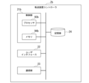
- FIG. 4 is a diagram showing an example of the hardware configuration of a first transfer device controller according to the embodiment;
- FIG. 4 is a diagram showing an example of the configuration of a control unit included in a first transfer device controller according to the embodiment;
- FIG. 4 is a diagram showing an example of the configuration of a second transfer device controller according to the embodiment;
- the figure which shows an example of a structure of the control part with which the 1st base station in embodiment is provided.
- the figure which shows an example of a structure of the control part with which the 2nd base station in embodiment is provided.
- FIG. 4 is a diagram showing an example of a hardware configuration of a first distributed station according to the embodiment;
- FIG. 4 is a diagram showing an example of the configuration of a control unit provided in the first distributed station according to the embodiment; The figure which shows an example of a structure of the 2nd distributed station in embodiment.
- FIG. 4 is a diagram showing an example of the configuration of a control unit included in a second distributed station according to the embodiment;
- the figure which shows an example of a structure of the control part with which the communication apparatus in embodiment is provided.
- the figure which shows an example of a structure of the control part with which the wireless controller in a modification is provided.
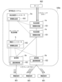
- FIG. 1 is an explanatory diagram illustrating an overview of a signal transfer system 100 according to an embodiment.
- the signal transfer system 100 is a system that transfers signals from one communication device to another communication device.
- the signal transfer system 100 includes, for example, a transfer device, a base station, and a control device for the transfer device, and transfers signals from a server to a wireless terminal and from the wireless terminal to the server.
- the signal transfer system 100 includes, for example, a transfer device, a distributed station, and a control device for the transfer device, and transfers signals from the central office to wireless terminals and from the wireless terminals to the central office.
- Application examples of such a signal transfer system 100 will be described later in detail, and first, an outline of the signal transfer system 100 will be described.
- the signal transfer system 100 includes an information acquisition section 101 and a communication control section 102 .
- the information acquisition unit 101 acquires network transfer information for each traffic flow from one communication device to the other communication device.
- Network forwarding information is information about traffic flows.
- Information about the traffic flow indicates, for example, the size of the frames and the transmission interval.
- the network transfer information thus includes, for example, information indicating the size and transmission interval of the frames.
- the frame size and transmission interval indicated by the information indicating the frame size and transmission interval are, for example, the downlink frame size and transmission interval.
- Information about traffic flow may indicate, for example, the transmission rate or the destination address. Therefore, the network transfer information may include, for example, information indicating the transmission rate, or may include information indicating the destination address.
- One communication device is, for example, the server described above, and in this case, the other communication device is, for example, a wireless terminal.
- the other communication device is, for example, the server described above.
- the downstream frame size indicated by the network transfer information is, for example, the size of a frame from the server to the wireless terminal. That is, in such a case, downlink means the direction from the server to the wireless terminal among the signal propagation directions.
- One communication device is, for example, the above-mentioned central office, and in this case, the other communication device is, for example, a wireless terminal.
- the other communication device is, for example, the above-mentioned central office.
- the downstream frame size indicated by the network transfer information is, for example, the size of the frame from the central office to the wireless terminal. That is, in such a case, downlink means the direction from the central office to the wireless terminal in the propagation direction of the signal.
- a communication device 900 in FIG. 1 is an example of one communication device, and a wireless terminal 901 in FIG. 1 is an example of the other communication device.
- communication device 900 may be, for example, a server, or may be, for example, a central office.
- the communication control unit 102 executes adjustment processing based on the network transfer information obtained by the information acquisition unit 101. Adjustment processing is processing for shortening the waiting time until a frame is transmitted according to a predetermined rule based on network transfer information.
- the process of shortening the waiting time until the frame is transmitted is, for example, a process of adjusting the frame transmission timing in Time Division Duplex (TDD) according to a predetermined rule (hereinafter referred to as "TDD timing adjustment process”. ).
- Frame transmission timing means the timing at which a frame is transmitted.
- the process of shortening the waiting time until a frame is transmitted may be, for example, a process of adjusting Transport Block Size (TBS) according to a predetermined rule (hereinafter referred to as "TBS adjustment process.” .
- the adjustment process may be, for example, a process of adjusting both the frame transmission timing in TDD and the TBS according to a predetermined rule. Therefore, the adjustment process is, for example, a process of performing one or both of the TDD timing adjustment process and the TBS adjustment process.
- the waiting time until the frame is transmitted in the adjustment process is, for example, the waiting time of the downstream transmission frame.
- a downstream transmission frame means a frame that is propagated in the downstream direction and is transmitted to a transmission destination such as the wireless terminal 901 . Therefore, when the destination is the wireless terminal 901, the downstream transmission frame is a frame transmitted to the wireless terminal 901 from one communication device such as a server or a central office.
- the frame transmission timing is, for example, the downstream transmission timing.
- the downlink transmission timing means the timing at which the downlink transmission frame is transmitted.
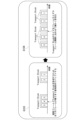
- FIG. 2 is a first explanatory diagram for explaining the effect of adjustment processing in the embodiment. More specifically, FIG. 2 is a diagram for explaining the effect of TDD timing adjustment processing in the embodiment.
- An image G101 in FIG. 2 shows an example of how signals are transmitted from the base station to the wireless terminal when the adjustment process is not performed. More specifically, the image G101 shows an example of how signals are transmitted when no adjustment processing is performed using five frames F1 to F5.
- the period between frame F2 and frame F3 is the upstream transmission timing in TDD.
- the downstream signal cannot be transmitted at this timing.
- the time interval between frames F1 and F2 the time interval between frames F2 and F3, and the time interval between frames F3 and F4 are uneven. This uneven frame spacing increases jitter.
- An image 102 in FIG. 2 shows an example of how signals are transmitted from the base station to the wireless terminal when the TDD timing adjustment process is performed. More specifically, image G102 shows an example of how signals are transmitted when TDD timing adjustment processing is performed using five frames F1 to F5. As described above, the TDD timing adjustment process is a process for making adjustments so as to shorten the waiting time of frames.
- An image G102 shows an example of the result of performing a process of dividing the TDD downlink and uplink transmission timings more finely than in the case of the image G101 based on the frame size and frame interval, as an example of the TDD timing adjustment process.
- dividing the transmission timing finely means, for example, setting the TDD downlink transmission time interval to an interval corresponding to the downlink frame size, and setting the TDD uplink transmission time interval to an interval corresponding to the transmission interval of the downlink frame. means. Therefore, in the example of image G102, the frame intervals are uniform. Therefore, jitter is reduced in the example of image G102.
- FIG. 3 is a second explanatory diagram for explaining the effect of adjustment processing in the embodiment. More specifically, FIG. 3 is a diagram explaining the effect of TBS adjustment processing in the embodiment.
- An image G103 in FIG. 3 shows an example of how signals are transmitted from the base station to the wireless terminal when the adjustment process is not performed. More specifically, the image G103 shows an example of how signals are transmitted when no adjustment processing is performed using five frames F1 to F5. In the example of image G103, frames 1 and 2 form one Transport Block.
- frames 3 to 5 form another Transport Block different from frames 1 and 2.
- Each Transport Block has a different size because it contains a different number of frames.
- a buffer occurs within the base station until all the frames are completed.
- the frame intervals are not uniform in the example of image G103. Therefore, jitter increases in the example of image G103.
- An image G104 in FIG. 3 shows an example of a signal transmitted from the base station to the wireless terminal when the TBS adjustment process is performed. More specifically, image G104 shows an example of how signals are transmitted when TBS adjustment processing is performed using five frames F1 to F5.
- An image G104 shows an example of the result of TBS adjustment processing in which the size of the Transport Block is divided more finely than in the image G103 based on the frame size and the frame interval.
- each of frames 1 to 5 forms one Transport Block. Therefore, the frame interval is uniform in the example of the image G104. Therefore, in the example of image G104, an increase in jitter is suppressed.
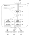
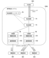
- FIG. 4 is a diagram showing a first application example of the signal transfer system 100 according to the embodiment.
- the signal transfer system 100 in the first application example will be referred to as a signal transfer system 100a.
- the signal transfer system 100 a transfers signals from the server 902 to the wireless terminal 901 and transfers signals from the wireless terminal 901 to the server 902 .
- Server 902 is an example of communication device 900 .
- the signal transfer system 100a includes one or more transfer devices 1a, a transfer device controller 2a, and one or more base stations 3a. Both the server 902 and the wireless terminal 901 are devices that transmit and receive signals.
- the transfer device 1a transfers the signal sent from the transfer source device to the transfer destination.
- the transfer device controller 2a controls the operation of each transfer device 1a included in the signal transfer system 100a.
- the transfer device controller 2a determines, for example, the destination to which each transfer device 1a transfers a signal.
- Base station 3 a is a base station that communicates with wireless terminal 901 . Through communication with the wireless terminal 901, the base station 3a transmits the signal transferred from the transfer device 1a to the wireless terminal 901, and transfers the signal received from the wireless terminal 901 to the transfer destination transfer device 1a. I do.
- Each transfer device 1a includes an information acquisition unit 101.
- the information acquisition unit 101 included in the transfer device 1a acquires network transfer information based on the signal received by the transfer device 1a.
- the transfer device controller 2a includes an information transfer unit 103.
- the information transfer unit 103 acquires network transfer information acquired by each information acquisition unit 101 .
- the information transfer unit 103 transfers the acquired network transfer information to a predetermined transfer destination such as the communication control unit 102 or the like.
- Each base station 3a includes a communication control section 102.
- the communication control unit 102 provided in the base station 3 a acquires the network transfer information acquired by the information transfer unit 103 .
- the communication control unit 102 provided in the base station 3a performs adjustment processing based on the acquired network transfer information.
- the base station 3a may be a Wi-Fi (registered trademark) access point, for example.
- the signal transfer system 100 does not necessarily have to be applied to a mobile communication system, and may be applied to a wireless communication system other than the mobile communication system.
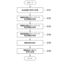
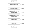
- FIG. 5 is a flowchart showing an example of the flow of processing executed by the signal transfer system 100a according to the embodiment. More specifically, an example of the flow of processing executed by the signal transfer system 100a when a signal is transmitted from the server 902 to the wireless terminal 901 is shown. The processing shown in FIG. 5 is repeated in the signal transfer system 100a.
- the transfer device 1a receives the signal transmitted by the server 902 (step S101).
- the information acquisition unit 101 included in the transfer device 1a acquires network transfer information based on the received signal (step S102).
- the information transfer unit 103 acquires the network transfer information acquired by the information acquisition unit 101 (step S103).
- the communication control unit 102 provided in the base station 3a acquires the network transfer information acquired by the information transfer unit 103 (step S104).
- the communication control unit 102 executes adjustment processing based on the network transfer information (step S105).
- the communication control unit 102 transmits a signal whose transmission timing or transport block size is adjusted to the wireless terminal 901 (step S106).
- step S105 since the adjustment process is performed in step S105, an increase in jitter is suppressed in the process performed by the base station 3a in step S106.
- FIG. 6 is a diagram showing a second application example of the signal transfer system 100 in the embodiment.
- the signal transfer system 100 in the second application example will be referred to as a signal transfer system 100b.
- Signal transfer system 100 b provides for transfer of signals from central office 903 to wireless terminal 901 and transfer of signals from wireless terminal 901 to central office 903 .
- Central office 903 is an example of communication device 900 .
- the signal transfer system 100b differs from the signal transfer system 100a in that a distributed station 4a is provided instead of the base station 3a.
- Central office 903 is a central office that transmits and receives signals.
- the distributed station 4 a is a distributed station that communicates with the wireless terminal 901 . Through communication with the wireless terminal 901, the distributed station 4a transmits to the wireless terminal 901 the signal transferred from the transfer device 1a, and transfers the signal received from the wireless terminal 901 to the transfer destination transfer device 1a. I do.
- Each distributed station 4a includes a communication control unit 102.
- the communication control unit 102 provided in the distributed station 4a acquires the network transfer information acquired by the information transfer unit 103.
- FIG. The communication control unit 102 provided in the distributed station 4a performs adjustment processing based on the acquired network transfer information.
- the central station and distributed stations in the example of FIG. 6 are, for example, the CU (Central Unit) and DU (Distributed Unit) in the mobile communication system.
- the transfer device 1a in the example of FIG. 6 is installed, for example, in a section called MMH (Mobile Midhaul).
- the central station may be the DU and the distributed stations may be the RU (Radio Unit).
- the transfer device 1a may be installed, for example, in a section called MFH (mobile fronthaul).
- the central station may be the Wi-Fi controller and the distributed stations may be Wi-Fi access points.
- the signal transfer system 100 does not necessarily have to be applied to a mobile communication system, and may be applied to a wireless communication system other than the mobile communication system.
- FIG. 7 is a flowchart showing an example of the flow of processing executed by the signal transfer system 100b in the embodiment. More specifically, an example of the flow of processing performed by the signal transfer system 100b when a signal is transmitted from the central office 903 to the wireless terminal 901 is shown. The processing shown in FIG. 7 is repeated in the signal transfer system 100b.
- the transfer device 1a receives the signal transmitted by the central office 903 (step S201).
- the information acquisition unit 101 included in the transfer device 1a acquires network transfer information based on the received signal (step S202).
- the information transfer unit 103 acquires the network transfer information acquired by the information acquisition unit 101 (step S203).
- the communication control unit 102 provided in the distributed station 4a acquires the network transfer information acquired by the information transfer unit 103 (step S204).
- the communication control unit 102 executes adjustment processing based on the network transfer information (step S205).
- the communication control unit 102 transmits a signal whose transmission timing or Transport Block Size has been adjusted to the wireless terminal 901 (step S206).
- step S205 since the adjustment process is executed in step S205, an increase in jitter is suppressed in the process executed by the distributed station 4a in step S206.
- FIG. 8 is a diagram showing a third application example of the signal transfer system 100 in the embodiment.
- the signal transfer system 100 in the third application example will be referred to as a signal transfer system 100c.
- the signal transfer system 100 c transfers signals from the server 902 to the wireless terminal 901 and transfers signals from the wireless terminal 901 to the server 902 .
- the signal transfer system 100c includes one or more transfer devices 1b, a transfer device controller 2b, and one or more base stations 3b.
- the transfer device 1b differs from the transfer device 1a in that it does not include the information acquisition unit 101.
- the transfer device controller 2b is different from the transfer device controller 2a in that the information transfer unit 103 is not provided.
- the base station 3 b is a base station that communicates with the wireless terminal 901 . Through communication with the wireless terminal 901, the base station 3b transmits the signal transferred from the transfer device 1b to the wireless terminal 901, and transfers the signal received from the wireless terminal 901 to the transfer destination transfer device 1b. I do.
- Each base station 3b includes an information acquisition unit 101 and a communication control unit 102. That is, the base station 3b differs from the base station 3a in that it includes an information acquisition unit 101.
- FIG. The information acquisition unit 101 provided in the base station 3b acquires network transfer information based on the signal received by the base station 3b.
- the communication control unit 102 provided in the base station 3b acquires the network transfer information acquired by the information acquisition unit 101.
- the communication control unit 102 provided in the base station 3b performs adjustment processing based on the acquired network transfer information.
- the base station 3b may be a Wi-Fi access point, for example.
- FIG. 9 is a flowchart showing an example of the flow of processing executed by the signal transfer system 100c according to the embodiment. More specifically, an example of the flow of processing executed by the signal transfer system 100c when a signal is transmitted from the server 902 to the wireless terminal 901 is shown. The processing shown in FIG. 9 is repeated in the signal transfer system 100c.
- the transfer device 1b receives the signal transmitted by the server 902 (step S301).
- the signal acquired by the transfer device 1b in step S301 reaches the base station 3b via zero or more transfer devices 1b. That is, the base station 3b receives the signal (step S302).
- the information acquisition unit 101 provided in the base station 3b acquires network transfer information based on the received signal (step S303).
- the communication control unit 102 provided in the base station 3b acquires the network transfer information acquired by the information acquisition unit 101 (step S304).
- the communication control unit 102 executes adjustment processing based on the network transfer information (step S305).
- the communication control unit 102 transmits the adjusted transmission timing or transport block size signal to the wireless terminal 901 (step S306).
- step S305 since the adjustment process is executed in step S305, an increase in jitter is suppressed in the process executed by the base station 3b in step S306.
- FIG. 10 is a diagram showing a fourth application example of the signal transfer system 100 according to the embodiment.
- the signal transfer system 100 in the fourth application example will be referred to as a signal transfer system 100d.
- Signal transfer system 100 d transfers signals from central office 903 to wireless terminal 901 and from wireless terminal 901 to central office 903 .
- the signal transfer system 100d differs from the signal transfer system 100c in that a distributed station 4b is provided instead of the base station 3b.
- the distributed station 4 b is a distributed station that communicates with the wireless terminal 901 . Through communication with the wireless terminal 901, the distributed station 4b transmits to the wireless terminal 901 the signal transferred from the transfer device 1b, and transfers the signal received from the wireless terminal 901 to the transfer destination transfer device 1b. I do.
- Each distributed station 4b includes an information acquisition unit 101 and a communication control unit 102. That is, the distributed station 4b differs from the distributed station 4a in that it includes an information acquisition unit 101.
- FIG. The information acquisition unit 101 provided in the distributed station 4b acquires network transfer information based on the signal received by the distributed station 4b.
- the communication control unit 102 provided in the distributed station 4b acquires the network transfer information acquired by the information acquisition unit 101.
- the communication control unit 102 provided in the distributed station 4b performs adjustment processing based on the acquired network transfer information.
- the central station and distributed stations in the example of FIG. 10 are, for example, the CU and DU in the mobile communication system, as in the example of FIG.
- the transfer device 1b in the example of FIG. 10 is installed, for example, in a section called MMH.
- the central station may be the DU and the distributed stations may be the RU.
- the transfer device 1b may be installed, for example, in a section called MFH.
- the central station may be the Wi-Fi controller and the distributed stations may be Wi-Fi access points.
- FIG. 11 is a flowchart showing an example of the flow of processing executed by the signal transfer system 100d according to the embodiment. More specifically, an example of the flow of processing executed by the signal transfer system 100d when a signal is transmitted from the central office 903 to the wireless terminal 901 is shown. The processing shown in FIG. 11 is repeated in the signal transfer system 100d.
- the transfer device 1b receives the signal transmitted by the central office 903 (step S401).
- the signal acquired by the transfer device 1b in step S401 reaches the distributed station 4b via zero or more transfer devices 1b. That is, the distributed station 4b receives the signal (step S402).
- the information acquisition unit 101 provided in the distributed station 4b acquires network transfer information based on the received signal (step S403).
- the communication control unit 102 provided in the distributed station 4b acquires the network transfer information acquired by the information acquisition unit 101 (step S404).
- the communication control unit 102 executes adjustment processing based on the network transfer information (step S405).
- the communication control unit 102 transmits the adjusted transmission timing or transport block size signal to the wireless terminal 901 (step S306).
- step S405 adjustment processing is performed in step S405, so an increase in jitter is suppressed in the processing performed by the base station 3b in step S406.
- the signal transfer system 100 configured in this manner controls communication based on network transfer information. Therefore, an increase in jitter can be suppressed.
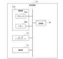
- FIG. 12 is a diagram showing an example of the hardware configuration of the transfer device 1a (first transfer device) according to the embodiment.
- the transfer device 1a includes a controller 11a including a processor 91a such as a CPU (Central Processing Unit) and a memory 92a connected via a bus, and executes a program.
- the transfer device 1a functions as a device including a control unit 11a, a user interface 12, a communication unit 13, and a storage unit 14 by executing a program.
- the processor 91a reads a program stored in the storage unit 14 and stores the read program in the memory 92a.
- the processor 91a executes a program stored in the memory 92a, so that the transfer device 1a functions as a device including the control section 11a, the user interface 12, the communication section 13, and the storage section .
- the control unit 11a controls the operations of various functional units included in the transfer device 1a.
- the user interface 12 includes input devices such as a mouse, keyboard, and touch panel.
- the user interface 12 may include an interface that connects these input devices to the transfer device 1a.
- the user interface 12 includes a display device such as a CRT (Cathode Ray Tube) display, a liquid crystal display, an organic EL (Electro-Luminescence) display, or the like.
- the user interface 12 may include an interface that connects these display devices to the transfer device 1a.
- the communication unit 13 includes an interface for connecting the transfer device 1a to an external device.
- the communication unit 13 communicates with an external device via wire or wireless.
- the external device is, for example, the device from which the signal is sent.
- the communication unit 13 receives a signal through communication with a signal transmission source device.
- An external device is, for example, a device to which a signal is transferred.
- the communication unit 13 transfers the signal to the signal transfer destination by communicating with the signal transfer destination device.
- the communication unit 13 transmits network transfer information to the information transfer unit 103, for example.
- the storage unit 14 is configured using a computer-readable storage medium device such as a magnetic hard disk device or a semiconductor storage device.
- the storage unit 14 stores various information about the transfer device 1a.
- the storage unit 14 stores, for example, various information generated as a result of processing executed by the control unit 11a.
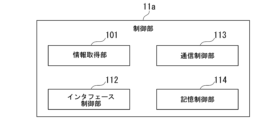
- FIG. 13 is a diagram showing an example of the configuration of the control unit 11a included in the transfer device 1a according to the embodiment.
- the control unit 11 a includes an information acquisition unit 101 , an interface control unit 112 , a communication control unit 113 and a storage control unit 114 .
- the interface control unit 112 controls operations of the user interface 12 .
- a communication control unit 113 controls the operation of the communication unit 13 .
- a memory control unit 114 controls the operation of the memory unit 14 .
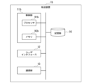
- FIG. 14 is a diagram showing an example of the configuration of the transfer device 1b (second transfer device) in the embodiment. 14 and 15 are assigned to components having the same functions as those of the transfer device 1a, and description thereof will be omitted.
- the transfer device 1b differs from the transfer device 1a in that it includes a control unit 11b instead of the control unit 11a.
- the control unit 11b differs from the control unit 11a in that it includes a processor 91b instead of the processor 91a, and in that it includes a memory 92b instead of the memory 92a. Further, the control unit 11b differs from the control unit 11a in that the information acquisition unit 101 is not provided.
- FIG. 15 is a diagram showing an example of the hardware configuration of the transfer device controller 2a (first transfer device controller) in the embodiment.
- the transfer device controller 2a includes a control unit 21a including a processor 93a such as a CPU and a memory 94a connected via a bus, and executes a program.
- the transfer device controller 2a functions as a device including a control unit 21a, a user interface 22, a communication unit 23, and a storage unit 24 by executing programs.
- the transfer device controller 2a causes the processor 93a to read the program stored in the storage unit 24 and store the read program in the memory 94a.
- the transfer device controller 2a functions as a device including the control unit 21a, the user interface 22, the communication unit 23, and the storage unit 24 by the processor 93a executing the program stored in the memory 94a.
- the control unit 21a controls the operations of various functional units included in the transfer device controller 2a.
- the user interface 22 includes, for example, input devices such as a mouse, keyboard, and touch panel.
- the user interface 22 may comprise an interface connecting these input devices to the transfer device controller 2a.
- the user interface 22 includes a display device such as a CRT display, a liquid crystal display, an organic EL display, or the like.
- the user interface 22 may comprise an interface connecting these display devices to the transfer device controller 2a.
- the communication unit 23 includes an interface for connecting the transfer device controller 2a to an external device.
- the communication unit 23 communicates with an external device via wire or wireless.
- the external device is, for example, the transfer device 1a or 1b.
- the external device is, for example, the base station 3a or the distributed station 4a.
- the communication unit 23 acquires network transfer information, for example.
- the communication unit 23 transfers the network transfer information to a predetermined transfer destination such as the communication control unit 102, for example.
- the storage unit 24 is configured using a computer-readable storage medium device such as a magnetic hard disk device or a semiconductor storage device.
- the storage unit 24 stores various information regarding the transfer device controller 2a.
- the storage unit 24 stores, for example, various information generated as a result of processing executed by the control unit 21a.
- FIG. 16 is a diagram showing an example of the configuration of the control unit 21a included in the transfer device controller 2a according to the embodiment.
- the control unit 21 a includes an information transfer unit 103 , an interface control unit 212 , a communication control unit 213 and a storage control unit 214 .
- the interface control unit 212 controls operations of the user interface 22 .
- a communication control unit 213 controls the operation of the communication unit 23 .
- a memory control unit 214 controls the operation of the memory unit 24 .
- FIG. 17 is a diagram showing an example of the configuration of the transfer device controller 2b (second transfer device controller) in the embodiment. 15 and 16 are assigned to components having the same functions as those of the transfer device controller 2a, and description thereof will be omitted.
- the transfer device controller 2b differs from the transfer device controller 2a in that it includes a control unit 21b instead of the control unit 21a.
- the control unit 21b differs from the control unit 21a in that it includes a processor 93b instead of the processor 93a, and in that it includes a memory 94b instead of the memory 94a.
- the control unit 21b differs from the control unit 21a in that the information transfer unit 103 is not provided.
- FIG. 18 is a diagram showing an example of the hardware configuration of the base station 3a (first base station) in the embodiment.
- the base station 3a includes a controller 31a including a processor 95a such as a CPU and a memory 96a connected via a bus, and executes a program.
- the base station 3a functions as a device including a control section 31a, a user interface 32, a communication section 33 and a storage section 34 by executing a program.
- the processor 95a reads the program stored in the storage unit 34 and stores the read program in the memory 96a.
- the processor 95a executes the program stored in the memory 96a, so that the base station 3a functions as a device including the control section 31a, the user interface 32, the communication section 33 and the storage section .
- the control unit 31a controls operations of various functional units provided in the base station 3a.
- the user interface 32 includes, for example, input devices such as a mouse, keyboard, and touch panel.
- the user interface 32 may comprise an interface connecting these input devices to the base station 3a.
- the user interface 32 includes a display device such as a CRT display, a liquid crystal display, an organic EL display, or the like.
- the user interface 32 may comprise an interface connecting these display devices to the base station 3a.
- the communication unit 33 includes an interface for connecting the base station 3a to an external device.
- the communication unit 33 communicates with an external device via wire or wireless.
- the external device is, for example, the transfer device 1a.
- the external device is the wireless terminal 901, for example.
- the operation of the communication section 33 is controlled by the communication control section 102 .
- the communication unit 33 acquires network transfer information through communication with the information transfer unit 103, for example.
- the storage unit 34 is configured using a computer-readable storage medium device such as a magnetic hard disk device or a semiconductor storage device.
- the storage unit 34 stores various information regarding the base station 3a.
- the storage unit 34 stores, for example, various information generated as a result of processing executed by the control unit 31a.
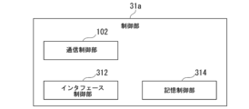
- FIG. 19 is a diagram showing an example of the configuration of the control unit 31a included in the base station 3a according to the embodiment.
- the control unit 31 a includes a communication control unit 102 , an interface control unit 312 and a storage control unit 314 .
- the interface control unit 312 controls operations of the user interface 32 .
- a memory control unit 314 controls the operation of the memory unit 24 .
- FIG. 20 is a diagram showing an example of the configuration of the base station 3b (second base station) in the embodiment. 18 and 19 are denoted by the same reference numerals as in FIGS. 18 and 19, and description thereof will be omitted.
- the base station 3b differs from the base station 3a in that it includes a controller 31b instead of the controller 31a.
- the controller 31b differs from the controller 31a in that it includes a processor 95b instead of the processor 95a, and in that it includes a memory 96b instead of the memory 96a.
- FIG. 21 is a diagram showing an example of the configuration of the control unit 31b included in the base station 3b according to the embodiment.
- the control unit 31b differs from the control unit 31a in that an information acquisition unit 101 is further provided.
- FIG. 22 is a diagram showing an example of the hardware configuration of the distributed station 4a (first distributed station) in the embodiment.
- the distributed station 4a includes a control unit 41a including a processor 97a such as a CPU and a memory 98a connected by a bus, and executes a program.
- the distributed station 4a functions as a device having a control unit 41a, a user interface 42, a communication unit 43, and a storage unit 44 by executing a program.
- the processor 97a reads the program stored in the storage unit 44 and stores the read program in the memory 98a.
- the processor 97a executes the program stored in the memory 98a, so that the distributed station 4a functions as a device comprising the control section 41a, the user interface 42, the communication section 43 and the storage section 44.
- the control unit 41a controls the operations of various functional units provided in the distributed station 4a.
- the user interface 42 includes, for example, input devices such as a mouse, keyboard, and touch panel.
- the user interface 42 may comprise an interface connecting these input devices to the distributed station 4a.
- the user interface 42 includes a display device such as a CRT display, a liquid crystal display, an organic EL display, or the like.
- the user interface 42 may comprise an interface connecting these display devices to the distributed station 4a.
- the communication unit 43 includes an interface for connecting the distributed station 4a to an external device.
- the communication unit 43 communicates with an external device via wire or wireless.
- the external device is, for example, the transfer device 1a.
- the external device is the wireless terminal 901, for example.
- the operation of the communication section 43 is controlled by the communication control section 102 .
- the communication unit 43 acquires network transfer information through communication with the information transfer unit 103, for example.
- the storage unit 44 is configured using a computer-readable storage medium device such as a magnetic hard disk device or a semiconductor storage device.
- the storage unit 44 stores various information about the distributed station 4a.
- the storage unit 44 stores, for example, various information generated as a result of processing executed by the control unit 41a.
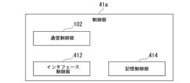
- FIG. 23 is a diagram showing an example of the configuration of the control unit 41a included in the distributed station 4a according to the embodiment.
- the control unit 41 a includes a communication control unit 102 , an interface control unit 412 and a storage control unit 414 .
- the interface control unit 412 controls operations of the user interface 42 .
- a memory control unit 414 controls the operation of the memory unit 44 .
- FIG. 24 is a diagram showing an example of the configuration of the distributed station 4b (second distributed station) in the embodiment. 22 and 23 are assigned to those having the same functions as those of the decentralized station 4b, and description thereof will be omitted.
- the decentralized station 4b differs from the decentralized station 4b in that it includes a controller 41b instead of the controller 41a.
- the controller 41b differs from the controller 41a in that it includes a processor 97b instead of the processor 97a, and in that it includes a memory 98b instead of the memory 98a.
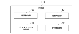
- FIG. 25 is a diagram showing an example of the configuration of the control unit 41b included in the distributed station 4b according to the embodiment.
- the control unit 41b differs from the control unit 41a in that an information acquisition unit 101 is further provided.
- FIG. 26 is a diagram illustrating an example of a hardware configuration of communication device 900 in the embodiment.
- the communication device 900 includes a control unit 910 including a processor 991 such as a CPU and a memory 992 connected via a bus, and executes a program.
- the communication device 900 functions as a device including a control unit 910, a user interface 920, a communication unit 930, and a storage unit 940 by executing programs.
- the communication device 900 causes the processor 991 to read a program stored in the storage unit 940 and store the read program in the memory 992 .
- the processor 991 executes a program stored in the memory 992 so that the communication device 900 functions as a device including a control section 910 , a user interface 920 , a communication section 930 and a storage section 940 .
- the control unit 910 controls operations of various functional units included in the communication device 900 .
- the user interface 920 includes input devices such as a mouse, keyboard, and touch panel. User interface 920 may comprise an interface that connects these input devices to communication device 900 .
- the user interface 920 includes a display device such as a CRT display, liquid crystal display, or organic EL display.
- User interface 920 may comprise interfaces for connecting these display devices to communication device 900 .
- the communication unit 930 includes an interface for connecting the communication device 900 to an external device.
- the communication unit 930 communicates with an external device via wire or wireless.
- the external device is, for example, the transfer device 1a or the transfer device 1b.
- the storage unit 940 is configured using a computer-readable storage medium device such as a magnetic hard disk device or a semiconductor storage device.
- the storage unit 940 stores various information regarding the communication device 900 .
- the storage unit 940 stores various information generated as a result of processing executed by the control unit 910, for example.
- FIG. 27 is a diagram showing an example of the configuration of the control unit 910 included in the communication device 900 according to the embodiment.
- the communication device 900 includes an interface control section 912 , a communication control section 913 and a storage control section 914 .
- the interface controller 912 controls operations of the user interface 920 .
- the communication control section 913 controls the operation of the communication section 930 .
- a memory control unit 914 controls the operation of the memory unit 940 .
- the communication control unit 102 or the information transfer unit 103 may execute analysis processing (hereinafter referred to as “analysis processing”) based on network transfer information acquired from a plurality of information acquisition units 101 .
- analysis processing includes, for example, processing for averaging values related to frame states such as frame sizes and frame transmission intervals received from a plurality of information acquisition units 101 .
- Analysis processing is, for example, processing for predicting future frame states such as future frame sizes and frame transmission intervals based on values related to frame states such as frame sizes and frame transmission intervals received from a plurality of information acquisition units 101. may include The result of analysis processing is used, for example, in adjustment processing for future communication, and has the effect of shortening the waiting time even for frames whose network transfer information has not been transferred to the communication control unit 102 .
- the signal transfer system 100a or 100c may further include a wireless controller 5.
- the radio controller 5 controls operations of base stations such as the base station 3a and the base station 3b.
- the signal transfer system 100 including the wireless controller 5 will be described below using the signal transfer system 100a as an example.
- the signal transfer system 100a including the wireless controller 5 will be referred to as a signal transfer system e.
- FIG. 28 is a diagram explaining an example of the configuration of the signal transfer system e in the modified example.
- the signal transfer system e differs from the signal transfer system 100a in that it includes a wireless controller 5 .
- the radio controller 5 controls the operation of the base station 3a.
- the wireless controller 5 has an information transfer section 103 .
- the information transfer unit 103 included in the wireless controller 5 acquires the network transfer information transmitted by the information transfer unit 103 included in the transfer device controller 2a.
- the information transfer unit 103 included in the wireless controller 5 transfers the received network transfer information to the base station 3a.
- the base station 3a may acquire the network transfer information via the information transfer section 103 provided in the wireless controller 5 instead of directly from the information transfer section 103 provided in the transfer device controller 2a.
- FIG. 29 is a diagram showing an example of the hardware configuration of the wireless controller 5 in the modified example.
- the wireless controller 5 includes a control unit 51 including a processor 993 such as a CPU and a memory 994 connected via a bus, and executes programs.
- the wireless controller 5 functions as a device including a control unit 51, a user interface 52, a communication unit 53, and a storage unit 54 by executing programs.
- the wireless controller 5 causes the processor 993 to read the program stored in the storage unit 54 and store the read program in the memory 994 .
- the processor 993 executes a program stored in the memory 994 so that the wireless controller 5 functions as a device including the control section 51 , the user interface 52 , the communication section 53 and the storage section 54 .
- the control unit 51 controls operations of various functional units provided in the wireless controller 5 .
- the user interface 52 includes, for example, input devices such as a mouse, keyboard, and touch panel. User interface 52 may comprise an interface that connects these input devices to wireless controller 5 .
- the user interface 52 includes a display device such as a CRT display, a liquid crystal display, an organic EL display, or the like.
- User interface 52 may comprise an interface connecting these display devices to wireless controller 5 .
- the communication unit 53 includes an interface for connecting the wireless controller 5 to an external device.
- the communication unit 53 communicates with an external device via wire or wireless.
- the external device is, for example, the transfer device controller 2a.
- the communication unit 53 acquires network transfer information through communication with the transfer device controller 2a.
- the external device is, for example, the base station 3a or the distributed station 4a.
- the communication unit 53 for example, transmits network transfer information to the base station 3a or distributed station 4a.
- the storage unit 54 is configured using a computer-readable storage medium device such as a magnetic hard disk device or a semiconductor storage device.
- the storage unit 54 stores various information regarding the wireless controller 5 .
- the storage unit 54 stores, for example, various information generated as a result of processing executed by the control unit 51 .
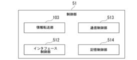
- FIG. 30 is a diagram showing an example of the configuration of the control section 51 included in the wireless controller 5 in the modified example.
- the control unit 51 includes an information transfer unit 103 , an interface control unit 512 , a communication control unit 513 and a storage control unit 514 .
- the interface control unit 512 controls operations of the user interface 52 .
- a communication control unit 513 controls the operation of the communication unit 53 .
- a memory control unit 514 controls the operation of the memory unit 54 .
- each device included in each of the signal transfer systems 100 to 100e may be implemented using a plurality of information processing devices that are communicatively connected via a network.
- All or part of each function of each device included in the signal transfer systems 100 to 100e uses hardware such as ASIC (Application Specific Integrated Circuit), PLD (Programmable Logic Device), and FPGA (Field Programmable Gate Array). may be implemented using The program may be recorded on a computer-readable recording medium.
- Computer-readable recording media include portable media such as flexible disks, magneto-optical disks, ROMs and CD-ROMs, and storage devices such as hard disks incorporated in computer systems.
- the program may be transmitted over telecommunications lines.
- Wireless terminal 902 Server 903... Central office 910... Control unit 920... User interface 930... Communication unit 940... Storage unit 912 ... interface control section 913 ... communication control section 914 ... storage control section 91a, 91b, 93a, 93b, 95a, 95b, 97a, 97b, 991, 993 ... processor 92a, 92b, 94a, 94b, 96a, 96b , 98a, 98b, 992, 994... memory
Landscapes
- Engineering & Computer Science (AREA)
- Computer Networks & Wireless Communication (AREA)
- Signal Processing (AREA)
- Mobile Radio Communication Systems (AREA)
Abstract
Description
図1は、実施形態の信号転送システム100の概要を説明する説明図である。信号転送システム100は、一方の通信装置から他方の通信装置への信号の転送を行うシステムである。信号転送システム100は、例えば転送装置と、基地局と、転送装置の制御装置とを備え、サーバから無線端末への信号の転送や、無線端末からサーバへの信号の転送を行う。信号転送システム100は、例えば転送装置と、分散局と、転送装置の制御装置となどを備え、中央局から無線端末への信号の転送や、無線端末から中央局への信号の転送を行う。このような信号転送システム100の適用例については詳細を後述し、まずは信号転送システム100の概要を説明する。
<基地局>
図12は、実施形態における転送装置1a(第1の転送装置)のハードウェア構成の一例を示す図である。転送装置1aは、バスで接続されたCPU(Central Processing Unit)等のプロセッサ91aとメモリ92aとを備える制御部11aを備え、プログラムを実行する。転送装置1aは、プログラムの実行によって制御部11a、ユーザインタフェース12、通信部13及び記憶部14を備える装置として機能する。
図15は、実施形態における転送装置コントローラ2a(第1の転送装置コントローラ)のハードウェア構成の一例を示す図である。転送装置コントローラ2aは、バスで接続されたCPU等のプロセッサ93aとメモリ94aとを備える制御部21aを備え、プログラムを実行する。転送装置コントローラ2aは、プログラムの実行によって制御部21a、ユーザインタフェース22、通信部23及び記憶部24を備える装置として機能する。
図18は、実施形態における基地局3a(第1の基地局)のハードウェア構成の一例を示す図である。基地局3aは、バスで接続されたCPU等のプロセッサ95aとメモリ96aとを備える制御部31aを備え、プログラムを実行する。基地局3aは、プログラムの実行によって制御部31a、ユーザインタフェース32、通信部33及び記憶部34を備える装置として機能する。
図22は、実施形態における分散局4a(第1の分散局)のハードウェア構成の一例を示す図である。分散局4aは、バスで接続されたCPU等のプロセッサ97aとメモリ98aとを備える制御部41aを備え、プログラムを実行する。分散局4aは、プログラムの実行によって制御部41a、ユーザインタフェース42、通信部43及び記憶部44を備える装置として機能する。
図26は、実施形態における通信装置900のハードウェア構成の一例を示す図である。通信装置900は、バスで接続されたCPU等のプロセッサ991とメモリ992とを備える制御部910を備え、プログラムを実行する。通信装置900は、プログラムの実行によって制御部910、ユーザインタフェース920、通信部930及び記憶部940を備える装置として機能する。
なお、通信制御部102又は情報転送部103は、複数の情報取得部101から取得したネットワーク転送情報に基づく分析の処理(以下「分析処理」という。)を実行してもよい。分析処理は、例えば複数の情報取得部101から受信したフレームサイズやフレーム送信間隔などのフレームの状態に関する値を平均する処理を含む。
図29は、変形例における無線コントローラ5のハードウェア構成の一例を示す図である。無線コントローラ5は、バスで接続されたCPU等のプロセッサ993とメモリ994とを備える制御部51を備え、プログラムを実行する。無線コントローラ5は、プログラムの実行によって制御部51、ユーザインタフェース52、通信部53及び記憶部54を備える装置として機能する。
Claims (11)
- 一方の通信装置から他方の通信装置への信号の転送を行う信号転送システムであって、
前記一方の通信装置から前記他方の通信装置に向かう各トラフィックフローについて、トラフィックフローに関する情報であるネットワーク転送情報を取得する情報取得部と、
前記情報取得部の取得した前記ネットワーク転送情報に基づいて、フレームの待ち時間を短縮させる処理である調整処理を実行する通信制御部と、
を備える信号転送システム。 - 前記調整処理は、予め定められた所定の規則にしたがいTime Division Duplex(TDD)においてフレームが送信されるタイミングであるフレーム送信タイミングを調整するTDDタイミング調整処理と、予め定められた所定の規則にしたがいTransport Block Size(TBS)を調整するTBS調整処理とのいずれか一方又は両方である、
請求項1に記載の信号転送システム。 - 前記他方の通信装置は無線端末であり、
前記フレーム送信タイミングは、前記一方の通信装置から前記無線端末へ送信されるフレームである下り送信フレーム、が送信されるタイミングである、
請求項2に記載の信号転送システム。 - 前記通信制御部は、前記ネットワーク転送情報に基づく分析の処理を実行する、
請求項1から3のいずれか一項に記載の信号転送システム。 - 前記情報取得部が取得した前記ネットワーク転送情報を、前記通信制御部に転送する情報転送部、
をさらに備え、
前記情報転送部は、前記ネットワーク転送情報に基づく分析の処理を実行する、
請求項1から4のいずれか一項に記載の信号転送システム。 - 前記分析の処理は、フレームの状態に関する値を平均する処理を含む、
請求項4又は5に記載の信号転送システム。 - 前記分析の処理は、フレームの状態に関する値に基づいて将来のフレームの状態を予測する処理を含む、
請求項4から6のいずれか一項に記載の信号転送システム。 - 前記トラフィックフローに関する情報は、下りのフレームのサイズ及び送信間隔を示す、
請求項1から7のいずれか一項に記載の信号転送システム。 - 前記トラフィックフローに関する情報は、伝送レートを示す、
請求項1から8のいずれか一項に記載の信号転送システム。 - 前記トラフィックフローに関する情報は、宛先アドレスを示す、
請求項1から9のいずれか一項に記載の信号転送システム。 - 一方の通信装置から他方の通信装置への信号の転送を行う信号転送方法であって、
前記一方の通信装置から前記他方の通信装置に向かう各トラフィックフローについて、トラフィックフローに関する情報であるネットワーク転送情報を取得する情報取得ステップと、
前記情報取得ステップで取得された前記ネットワーク転送情報に基づいて、フレームの待ち時間を短縮させる処理である調整処理を実行する通信制御ステップと、
を有する信号転送方法。
Priority Applications (3)
| Application Number | Priority Date | Filing Date | Title |
|---|---|---|---|
| PCT/JP2022/007921 WO2023162149A1 (ja) | 2022-02-25 | 2022-02-25 | 信号転送システム及び信号転送方法 |
| US18/727,916 US20250097161A1 (en) | 2022-02-25 | 2022-02-25 | Signal transfer system and signal transfer method |
| JP2024502381A JP7783532B2 (ja) | 2022-02-25 | 2022-02-25 | 信号転送システム及び信号転送方法 |
Applications Claiming Priority (1)
| Application Number | Priority Date | Filing Date | Title |
|---|---|---|---|
| PCT/JP2022/007921 WO2023162149A1 (ja) | 2022-02-25 | 2022-02-25 | 信号転送システム及び信号転送方法 |
Publications (1)
| Publication Number | Publication Date |
|---|---|
| WO2023162149A1 true WO2023162149A1 (ja) | 2023-08-31 |
Family
ID=87765072
Family Applications (1)
| Application Number | Title | Priority Date | Filing Date |
|---|---|---|---|
| PCT/JP2022/007921 Ceased WO2023162149A1 (ja) | 2022-02-25 | 2022-02-25 | 信号転送システム及び信号転送方法 |
Country Status (3)
| Country | Link |
|---|---|
| US (1) | US20250097161A1 (ja) |
| JP (1) | JP7783532B2 (ja) |
| WO (1) | WO2023162149A1 (ja) |
Citations (2)
| Publication number | Priority date | Publication date | Assignee | Title |
|---|---|---|---|---|
| US20150049678A1 (en) * | 2013-08-15 | 2015-02-19 | General Dynamics Broadband, Inc. | Apparatus and Methods for Semi-Persistent Scheduling |
| WO2019138520A1 (ja) * | 2018-01-11 | 2019-07-18 | 富士通株式会社 | 無線通信システム、端末、通信方法、制御装置、無線装置およびユーザデータ処置装置 |
-
2022
- 2022-02-25 JP JP2024502381A patent/JP7783532B2/ja active Active
- 2022-02-25 WO PCT/JP2022/007921 patent/WO2023162149A1/ja not_active Ceased
- 2022-02-25 US US18/727,916 patent/US20250097161A1/en active Pending
Patent Citations (2)
| Publication number | Priority date | Publication date | Assignee | Title |
|---|---|---|---|---|
| US20150049678A1 (en) * | 2013-08-15 | 2015-02-19 | General Dynamics Broadband, Inc. | Apparatus and Methods for Semi-Persistent Scheduling |
| WO2019138520A1 (ja) * | 2018-01-11 | 2019-07-18 | 富士通株式会社 | 無線通信システム、端末、通信方法、制御装置、無線装置およびユーザデータ処置装置 |
Also Published As
| Publication number | Publication date |
|---|---|
| US20250097161A1 (en) | 2025-03-20 |
| JP7783532B2 (ja) | 2025-12-10 |
| JPWO2023162149A1 (ja) | 2023-08-31 |
Similar Documents
| Publication | Publication Date | Title |
|---|---|---|
| CN107528680B (zh) | 基于工业互联网现场层总线架构实时传输方法及装置 | |
| JP2007300630A (ja) | 無線通信システムにおいてsduの分割及び番号付けを行う方法及び装置 | |
| JP2021141618A (ja) | ユーザ装置 | |
| US20130235727A1 (en) | Methods, systems, and computer readable media for preventing traffic congestion within a long term evolution (lte) multi-user equipment (multi-ue) simulator device | |
| EP3896964B1 (en) | Data processing method, apparatus and device, and storage medium | |
| US12471092B2 (en) | Dynamic wireless network architecture to serve uplink-centric and downlink-centric user applications | |
| CN109475002B (zh) | 一种下行数据传输的缓存方法、终端及基站 | |
| WO2017117929A1 (zh) | 一种数据传输方法和设备 | |
| US10938600B2 (en) | Forwarding data between an array of baseband units and an array of radio heads in a distributed wireless system using TDM switches | |
| JP2023536758A (ja) | 制御シグナリング伝送方法、制御シグナリング取得方法、機器および記憶媒体 | |
| CN112822125B (zh) | 一种业务流的传输方法、装置、设备及存储介质 | |
| JP7783532B2 (ja) | 信号転送システム及び信号転送方法 | |
| US20110265137A1 (en) | Method and system for isochronous data stream management in high speed audio/video networks | |
| WO2023013089A1 (ja) | 通信システムおよび通信制御方法 | |
| CN116193473B (zh) | 一种回传链路选择方法、装置、设备及介质 | |
| WO2021159305A1 (zh) | 通信方法及装置 | |
| CN116887384A (zh) | 基于无蜂窝网系统的通信方法、装置、系统、设备及介质 | |
| JP7260762B2 (ja) | 通信制御装置、通信制御方法、及びプログラム | |
| JP2024523612A (ja) | キャリアアグリゲーションに基づく情報報告方法、装置、媒体及び電子デバイス | |
| WO2024166251A1 (ja) | 無線端末、信号転送システム及び信号処理方法 | |
| US20260019878A1 (en) | Signal transfer system, base station apparatus, transfer control apparatus and signal transfer method | |
| JP7243059B2 (ja) | 基地局、無線端末、無線通信システム並びに無線通信制御方法及びプログラム | |
| US20240015575A1 (en) | Coordinating wireless transmissions using puncturing | |
| JP7697532B2 (ja) | 中継装置、通信システム、及び中継方法 | |
| WO2025253513A1 (ja) | 無線通信システム、無線通信方法、無線通信装置及び無線通信プログラム |
Legal Events
| Date | Code | Title | Description |
|---|---|---|---|
| 121 | Ep: the epo has been informed by wipo that ep was designated in this application |
Ref document number: 22928676 Country of ref document: EP Kind code of ref document: A1 |
|
| WWE | Wipo information: entry into national phase |
Ref document number: 18727916 Country of ref document: US |
|
| ENP | Entry into the national phase |
Ref document number: 2024502381 Country of ref document: JP Kind code of ref document: A |
|
| NENP | Non-entry into the national phase |
Ref country code: DE |
|
| 122 | Ep: pct application non-entry in european phase |
Ref document number: 22928676 Country of ref document: EP Kind code of ref document: A1 |
|
| WWP | Wipo information: published in national office |
Ref document number: 18727916 Country of ref document: US |