WO2023157809A1 - レーザ溶接方法 - Google Patents
レーザ溶接方法 Download PDFInfo
- Publication number
- WO2023157809A1 WO2023157809A1 PCT/JP2023/004860 JP2023004860W WO2023157809A1 WO 2023157809 A1 WO2023157809 A1 WO 2023157809A1 JP 2023004860 W JP2023004860 W JP 2023004860W WO 2023157809 A1 WO2023157809 A1 WO 2023157809A1
- Authority
- WO
- WIPO (PCT)
- Prior art keywords
- laser
- irradiation
- laser light
- welding method
- laser beam
- Prior art date
- Legal status (The legal status is an assumption and is not a legal conclusion. Google has not performed a legal analysis and makes no representation as to the accuracy of the status listed.)
- Ceased
Links
Images






Classifications
-
- B—PERFORMING OPERATIONS; TRANSPORTING
- B23—MACHINE TOOLS; METAL-WORKING NOT OTHERWISE PROVIDED FOR
- B23K—SOLDERING OR UNSOLDERING; WELDING; CLADDING OR PLATING BY SOLDERING OR WELDING; CUTTING BY APPLYING HEAT LOCALLY, e.g. FLAME CUTTING; WORKING BY LASER BEAM
- B23K26/00—Working by laser beam, e.g. welding, cutting or boring
-
- B—PERFORMING OPERATIONS; TRANSPORTING
- B23—MACHINE TOOLS; METAL-WORKING NOT OTHERWISE PROVIDED FOR
- B23K—SOLDERING OR UNSOLDERING; WELDING; CLADDING OR PLATING BY SOLDERING OR WELDING; CUTTING BY APPLYING HEAT LOCALLY, e.g. FLAME CUTTING; WORKING BY LASER BEAM
- B23K26/00—Working by laser beam, e.g. welding, cutting or boring
- B23K26/20—Bonding
- B23K26/21—Bonding by welding
-
- B—PERFORMING OPERATIONS; TRANSPORTING
- B23—MACHINE TOOLS; METAL-WORKING NOT OTHERWISE PROVIDED FOR
- B23K—SOLDERING OR UNSOLDERING; WELDING; CLADDING OR PLATING BY SOLDERING OR WELDING; CUTTING BY APPLYING HEAT LOCALLY, e.g. FLAME CUTTING; WORKING BY LASER BEAM
- B23K26/00—Working by laser beam, e.g. welding, cutting or boring
- B23K26/20—Bonding
- B23K26/32—Bonding taking account of the properties of the material involved
-
- H—ELECTRICITY
- H01—ELECTRIC ELEMENTS
- H01M—PROCESSES OR MEANS, e.g. BATTERIES, FOR THE DIRECT CONVERSION OF CHEMICAL ENERGY INTO ELECTRICAL ENERGY
- H01M10/00—Secondary cells; Manufacture thereof
- H01M10/04—Construction or manufacture in general
-
- H—ELECTRICITY
- H01—ELECTRIC ELEMENTS
- H01M—PROCESSES OR MEANS, e.g. BATTERIES, FOR THE DIRECT CONVERSION OF CHEMICAL ENERGY INTO ELECTRICAL ENERGY
- H01M10/00—Secondary cells; Manufacture thereof
- H01M10/05—Accumulators with non-aqueous electrolyte
- H01M10/058—Construction or manufacture
- H01M10/0585—Construction or manufacture of accumulators having only flat construction elements, i.e. flat positive electrodes, flat negative electrodes and flat separators
-
- Y—GENERAL TAGGING OF NEW TECHNOLOGICAL DEVELOPMENTS; GENERAL TAGGING OF CROSS-SECTIONAL TECHNOLOGIES SPANNING OVER SEVERAL SECTIONS OF THE IPC; TECHNICAL SUBJECTS COVERED BY FORMER USPC CROSS-REFERENCE ART COLLECTIONS [XRACs] AND DIGESTS
- Y02—TECHNOLOGIES OR APPLICATIONS FOR MITIGATION OR ADAPTATION AGAINST CLIMATE CHANGE
- Y02E—REDUCTION OF GREENHOUSE GAS [GHG] EMISSIONS, RELATED TO ENERGY GENERATION, TRANSMISSION OR DISTRIBUTION
- Y02E60/00—Enabling technologies; Technologies with a potential or indirect contribution to GHG emissions mitigation
- Y02E60/10—Energy storage using batteries
Definitions
- the present invention relates to a laser welding method.
- Patent Document 1 a power storage device having a portion where a metal member and a plurality of metal foils are joined by laser welding is known (for example, Patent Document 1).
- one of the objects of the present invention is, for example, when joining a metal member and a plurality of metal foils by laser welding, a new improvement that makes it difficult to generate a part where the metal foil is extended or cut. to obtain a laser welding method that is optimized.
- the laser welding method of the present invention is, for example, a laser welding method for welding a metal member and a laminate of metal foils by irradiating a laser beam.
- a new and improved laser welding method that makes it difficult to generate a portion where the metal foil is extended or cut. can be obtained.
- FIG. 1 is an exemplary schematic configuration diagram of a laser processing apparatus according to an embodiment.
- FIG. 2 is an exemplary and schematic cross-sectional view of a battery including a metal bonded body to be processed by the laser processing apparatus of the embodiment.
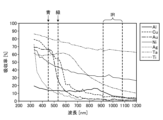
- FIG. 3 is a graph showing the light absorptance of a metal with respect to the wavelength of the irradiated laser light.
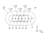
- FIG. 4 is an exemplary and schematic plan view showing a laser beam spot formed on the surface of the object to be processed by the laser processing apparatus of the embodiment.
- FIG. 5 is an exemplary flow chart showing the procedure of the laser welding method of the embodiment.
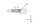
- FIG. 6 is an exemplary and schematic cross-sectional view of an object to be processed at the stage where the first step of the laser welding method of the first embodiment is finished.
- FIG. 1 is an exemplary schematic configuration diagram of a laser processing apparatus according to an embodiment.
- FIG. 2 is an exemplary and schematic cross-sectional view of a battery including a metal bonded body to be processed by the
- FIG. 7 is an exemplary and schematic cross-sectional view of a metal joined body welded by the laser welding method of the first embodiment.
- FIG. 8 is an enlarged view of section VIII of FIG. 9 is an enlarged view of the IX section of FIG. 7.
- FIG. 10 is a timing chart showing an example of temporal changes in the power of the laser beam irradiated in the second step of the laser welding method of the first embodiment.
- FIG. 11 is an exemplary and schematic plan view showing a laser beam irradiation region formed on the surface of the object to be processed in the second step of the laser welding method of the first embodiment.
- FIG. 12 is a schematic cross-sectional view of an example different from FIG. 7 of the metal joined body welded by the laser welding method of the first embodiment.
- FIG. 13 is an exemplary and schematic cross-sectional view of an object to be processed at the stage where the first step of the laser welding method of the second embodiment is finished.
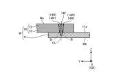
- FIG. 14 is an exemplary and schematic cross-sectional view of an object to be processed at a stage in the middle of the second process of the laser welding method of the second embodiment.
- FIG. 15 is an exemplary and schematic cross-sectional view of an object to be processed at the stage where the second process of the laser welding method of the second embodiment is finished.
- FIG. 16 is an exemplary and schematic cross-sectional view of an object to be processed at a stage in the middle of the third step of the laser welding method of the modification in which the irradiation direction of the laser beam of the second embodiment is changed.
- Exemplary embodiments of the present invention are disclosed below.
- the configurations of the embodiments shown below and the actions and effects brought about by the configurations are examples.
- the present invention can be realized by configurations other than those disclosed in the following embodiments.
- the X direction is indicated by an arrow X
- the Y direction is indicated by an arrow Y
- the Z direction is indicated by an arrow Z.
- the X-, Y-, and Z-directions intersect and are orthogonal to each other.
- the Z direction is the normal direction of the surface Wa of the workpiece W, the thickness direction of the metal member 11 and the metal foil 12 , and the lamination direction of the plurality of metal foils 12 .
- FIG. 1 is a schematic configuration diagram of a laser processing apparatus 100 according to an embodiment.
- the laser processing apparatus 100 includes a laser device 111, a laser device 112, an optical head 120, and optical fibers 131 and 132.
- the laser processing apparatus 100 can laser-weld the workpiece W by irradiating the laser beam L.
- the laser processing device 100 is also called a laser welding device.
- the laser devices 111 and 112 each have a laser oscillator, and are configured to output laser light with a power of, for example, several kW.
- Laser devices 111 and 112 each output laser light with a wavelength of 400 [nm] or more and 1200 [nm] or less.
- the laser devices 111 and 112 internally have laser light sources such as fiber lasers, semiconductor lasers (elements), YAG lasers, and disk lasers. Also, the laser devices 111 and 112 may be configured to output multimode laser light with a power of several kW as the total output of a plurality of light sources.
- the laser device 111 outputs a first laser beam, and the laser device 112 outputs a second laser beam.
- the optical fibers 131 and 132 optically connect the laser devices 111 and 112 and the optical head 120 .
- the optical fibers 131 and 132 guide the laser beams output from the laser devices 111 and 112 to the optical head 120, respectively.
- the optical head 120 is an optical device that irradiates the workpiece W with laser light input from the laser devices 111 and 112 .
- the optical head 120 includes a collimator lens 121 , a condenser lens 122 , a mirror 123 , a filter 124 and a galvanometer scanner 126 .
- Collimator lens 121, condenser lens 122, mirror 123, filter 124, and galvanometer scanner 126 are also referred to as optical components.
- the collimating lenses 121 (121-1, 121-2) collimate the laser beams input via the optical fibers 131, 132, respectively.
- the collimated laser light becomes parallel light.
- the mirror 123 reflects the first laser beam collimated by the collimator lens 121-1 and directs it to the galvanometer scanner 126.
- the filter 124 is a high-pass filter that transmits the first laser beam and reflects the second laser beam without transmitting it.
- the first laser light from mirror 123 is transmitted through filter 124 and directed to galvanometer scanner 126 .
- the second laser beam from the collimator lens 121-2 is reflected by the filter 124 and travels toward the galvanometer scanner 126.
- the galvanometer scanner 126 has a plurality of mirrors 126a and 126b. By changing the angles of the plurality of mirrors 126a and 126b, it is possible to switch the output direction of the laser light L from the optical head 120, thereby changing the irradiation position of the laser light L on the surface Wa of the workpiece W. can.
- the angles of the mirrors 126a, 126b are each changed, for example, by motors (neither shown) controlled by a controller.
- the optical head 120 can scan the surface Wa of the workpiece W with the laser light L by changing the output direction of the laser light L while irradiating it.
- the condensing lens 122 condenses the laser light as parallel light emitted by the galvanometer scanner 126, and irradiates the processing target W as laser light L (output light).
- the laser light L output from the optical head 120 includes the first laser light and the second laser light.
- the workpiece W has a metal member 11 and a laminate 16 of metal foils 12 placed on the metal member 11 .
- the metal member 11 is, for example, a plate-shaped member that extends across the Z direction at the welded portion and its peripheral portion.
- the laminated body 16 has a plurality of metal foils 12 laminated in the Z direction in an arrangement crossing the Z direction in the welded portion and its peripheral portion.
- the metal member 11 and the laminate 16 are stacked in the Z direction.
- the laminate 16 is superimposed on the surface 11a located at the end of the metal member 11 in the Z direction.
- the surface positioned at the end of the laminate 16 in the Z direction is the front surface Wa of the object W to be processed
- the surface positioned at the end of the metal member 11 opposite to the Z direction is the back surface Wb of the object W to be processed.
- a laser beam L is emitted from the optical head 120 substantially along the negative Z direction, and is irradiated onto the surface Wa.
- a spot of the laser beam L is scanned on the surface Wa by the operation of the galvanometer scanner 126 .
- a welded portion 14 is formed from the surface Wa through the laminate 16 to the metal member 11, and the metal member 11 and the laminate 16 are joined via the welded portion 14.
- a body 10 is formed.
- the metal bonded body 10 has a metal member 11 , a laminate 16 and a welded portion 14 .
- the weld 14 is also referred to as weld metal.
- the metal member 11, the plurality of metal foils 12, and the welded portion 14 are all conductors.
- the welded portion 14 electrically connects the metal member 11 and the plurality of metal foils 12 .
- the metal member 11 and the metal foil 12 are made of, for example, pure aluminum or an aluminum-based metal such as an aluminum alloy.
- the metal member 11 and the metal foil 12 may be made of a material other than the aluminum-based metal, such as a copper-based metal such as oxygen-free copper or a copper alloy.
- FIG. 2 is a cross-sectional view of a battery 1 as an electrical product having a metal bonded body 10.
- FIG. A battery 1 is one application example of the metal bonded body 10 .
- the metal bonded body 10 is an example of an electrical component as a conductor, and an example of an electrical component included in an electrical product.
- An electrical component may also be referred to as a component part of an electrical product.
- the battery 1 shown in FIG. 2 is, for example, a laminated lithium ion battery cell.
- the battery 1 has two film-like exterior materials 20 .
- a storage chamber 20 a is formed between the two exterior materials 20 .
- a plurality of flat positive electrode materials 13p, a plurality of flat negative electrode materials 13m, and a plurality of flat separators 15 are accommodated in the storage chamber 20a.
- the positive electrode material 13p and the negative electrode material 13m are alternately stacked with the separator 15 interposed therebetween.
- a metal foil 12 extends from each of the plurality of positive electrode materials 13p and the plurality of negative electrode materials 13m.
- FIG. 1 In the example of FIG.
- the plurality of metal foils 12 extending from each of the positive electrode materials 13p are overlapped on the metal member 11p (11) at the Y-direction end of the battery 1, and the metal member 11p (11 ) and a plurality of metal foils 12 are welded together.
- the metal member 11p On the positive electrode side, only a portion of the metal member 11p is exposed outside the exterior material 20, and the other portion of the metal member 11p, the plurality of metal foils 12, and the welded portion 14 are exposed outside the exterior material 20. not.
- Metal member 11 p constitutes a positive electrode terminal of battery 1 .
- the plurality of metal foils 12 extending from each of the negative electrode materials 13m are overlapped on the metal member 11m (11) at the end of the battery 1 opposite to the Y direction, and the metal member 11m (11) is overlapped at the end. and a plurality of metal foils 12 are welded together.
- the metal member 11m constitutes a negative electrode terminal of the battery 1. As shown in FIG.
- FIG. 3 is a graph showing the light absorptance of each metal material with respect to the wavelength of the laser light L to be irradiated.
- the horizontal axis of the graph in FIG. 3 is the wavelength, and the vertical axis is the absorptance.
- FIG. 3 shows the relationship between wavelength and absorptance for aluminum (Al), copper (Cu), gold (Au), nickel (Ni), silver (Ag), tantalum (Ta), and titanium (Ti). It is shown.
- the use of blue or green laser light with a shorter wavelength is more effective than the use of infrared (IR) laser light. It can be seen that the absorption rate is higher.
- the object W to be processed When the object W to be processed is irradiated with a laser beam having a relatively low absorptance and a relatively long wavelength, the light energy is reflected by the object W to be processed, so that the object W to be processed is affected by heat. it gets harder. Therefore, a relatively high power must be applied to obtain a sufficiently deep melted region. In that case, energy is suddenly applied to the center of the beam, causing sublimation and forming a keyhole. However, irradiation with a high-power laser beam may destabilize the molten pool and cause spatter and voids. In addition, when the object W to be processed includes the metal foil 12, the metal foil 12 is thin, so there is a risk that the metal foil 12 may be easily stretched or cut.
- the object W to be processed is irradiated with a laser beam having a relatively high absorption rate and a relatively short wavelength, most of the incident light energy is absorbed by the object W to be processed, and thermal energy is likely to be obtained. . That is, the melting is of the heat conduction type without the formation of a keyhole, and the molten pool is easily stabilized.
- a laser beam L including two laser beams (a first laser beam and a second laser beam) having different wavelengths is output from the optical head 120, and the laser beam L is applied to the surface Wa of the object W to be processed.
- the metal member 11 and the laminate 16 are welded by irradiation.
- the laser device 111 (see FIG. 1) outputs laser light with a wavelength of, for example, 800 [nm] or more and 1200 [nm] or less as the first laser light having a longer wavelength than the second laser light.
- the laser device 111 has, for example, a fiber laser, a semiconductor laser (element), or the like as a laser light source.
- the laser device 112 outputs a laser beam with a wavelength of 550 [nm] or less, for example, as a second laser beam having a shorter wavelength than the first laser beam.
- the laser device 112 has, for example, a semiconductor laser (element) as a laser light source. Further, it is more preferable that the laser device 112 outputs the second laser light having a wavelength of 400 [nm] or more and 500 [nm] or less, which has a higher absorption rate.
- FIG. 4 shows an example of the spot S of the laser beam L formed on the surface Wa.
- the spot S of the laser beam L has a spot S1 of the first laser beam L1 and a spot S2 of the second laser beam L2.
- Spots S, S1, and S2 are instantaneous irradiation regions of laser light.
- d, d1 and d2 indicate the diameters of spots S, S1 and S2.
- the size of spot S2 (diameter d2) is larger than the size of spot S1 (diameter d1), and spot S1 is positioned within spot S2.
- the outer edge S1a of the spot S1 is located inside the outer edge S2a of the spot S2.
- the spot S of the laser light L is scanned on the surface Wa in the scanning direction SD
- at least a partial area A2f of the spot S2 is located ahead of the spot S1 in the scanning direction SD. is preferred.
- the spot S (laser beam L) is scanned, the area (spot S1) irradiated with the first laser beam L1 can be heated in advance by the second laser beam L2. Also in this case, it becomes easier to form a deeper molten pool with less energy than when the first laser beam L1 is irradiated alone.
- the molten pool can be further stabilized, the occurrence of spatters and voids is suppressed, and the metal foil 12 is less likely to stretch or break. effect is obtained.
- the two centers may be shifted from each other.
- the spot S1 may partially extend behind the spot S2 in the scanning direction SD.
- the diameters of the spots S1 and S2 on the surface Wa can be defined as the diameter of the region of intensity equal to or greater than 1/ e2 of the peak intensity.
- the length in the direction (width direction) perpendicular to the scanning direction SD and perpendicular to the Z direction of the region where the intensity is 1/e 2 or more of the peak intensity is the diameter or width of the spot. can be defined.
- the welded portion 14 When the laser beam L is scanned on the surface Wa in the scanning direction SD, the welded portion 14 has the cross-sectional shape shown in FIG. 1 and extends in the scanning direction SD.
- FIG. 5 is a flow chart showing an example of a procedure of laser welding the workpiece W by the laser processing apparatus 100.
- the object W to be processed in which the metal member 11 and the plurality of metal foils 12 are integrally held, is brought into a state where the surface Wa thereof can be irradiated with the laser beam L (not shown). (S11).
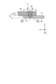
- FIG. 6 is a cross-sectional view of the workpiece W on which the first welded portion 14F is formed in S12. As shown in FIG. 6 , the first welded portion 14 ⁇ /b>F formed at S ⁇ b>12 extends from the front surface Wa in the negative Z direction, penetrates the laminate 16 , and reaches the metal member 11 .
- a dashed-dotted line CL in the drawing indicates a center line passing through the center C of the spot S of the laser beam L and extending in the Z direction.
- the scanning direction SD is the X direction and the width direction with respect to scanning is the Y direction, but the scanning direction SD is not limited to the X direction.
- FIG. 7 is a cross-sectional view of the workpiece W (metal joined body 10) on which the welded portion 14 is formed in S13.
- the welded portion 14 formed in S13 expands the Y-direction width of the first welded portion 14F formed in S12 at least in the vicinity of the Z-direction end (surface Wa). It will look like this.
- the laser beam L is applied to the workpiece W at least twice in S12 and S13.
- S12 is an example of the first step
- S13 is an example of the second step.
- FIG. 8 is an enlarged view of section VIII in FIG.
- the laser beam L including the first laser beam L1 with the long wavelength and the second laser beam L2 with the short wavelength is irradiated in S12 as described above, as shown in FIG.
- the metal foil 12 is cut at the portion in contact with the first welded portion 14F to form a gap G, or the metal foil 12 is extended at the portion in contact with the first welded portion 14F. In some cases, an excessively thin thin portion 12n may be formed.
- the thin portion 12n is also called a neck portion or a constricted portion.
- the diameter d of the spot S (the diameter d2 of the spot S2) is the width wp1 of the first welded portion 14F when the laser beam L is scanned in S12, or the width wp1 when the laser beam L is irradiated at a fixed point in S12.
- the diameter dp1 is larger than the diameter dp1 of the first welded portion 14F so that the region A2 includes adjacent portions Aa on both sides of the first welded portion 14F.
- the adjacent portion Aa is, for example, a belt-like or ring-shaped region extending substantially around the boundary B or the gap G on the surface Wa.
- Boundary B is an example of a connecting portion.
- FIG. 9 is an enlarged view of the IX section in FIG.
- the irradiation of the laser beam L under the predetermined conditions in S13 forms the welded portion 14 having a shape in which the width in the Y direction of the first welded portion 14F is expanded.
- the gap G and the excessively thin thin portion 12n as formed in FIG. 8 can be suppressed. That is, by S13, the first welded portion 14F and the metal foil 12 can be joined in a better state.
- S13 can be said to be a step of repairing or improving the bonding state in S12.
- the inventors have found that the gap G and the excessively thin portion 12n are suppressed by irradiating the laser beam L under predetermined conditions in S12 and S13 as described above. It has been found that a metal bonded body 10 can be formed.
- the first welded portion 14F and the welded portion 14 were formed by scanning the spot S of the laser beam L on the surface Wa. By scanning, the first welded portion 14F and the welded portion 14 over a wider range can be formed in a shorter time.
- the spot S of the laser light L was scanned on the same line (scanning section) on the surface Wa in both S12 and S13.
- the diameter d1 of the spot S1 of the first laser beam L1 is set to 20 to 40 [ ⁇ m]
- the diameter d2 of the spot S2 of the second laser beam L2 is set to 300 to 350 [ ⁇ m].
- the power of the first laser beam L1 400 to 500 [W]
- the power of the second laser beam L2 100 to 200 [W]
- S13 The power of the first laser beam L1: 100 to 200 [W]
- the power of the second laser beam L2 100 to 200 [W]
- the scanning speed 0.1 to 0.2 [m/sec].
- the amount of energy (total amount) given to the workpiece W by the irradiation of the laser beam L in S13 is made larger than the amount of energy (total amount) given to the workpiece W by the irradiation of the laser beam L in S12.
- the welded portion 14 having a wider width, ie, a larger volume, than the first welded portion 14F formed in S12 can be formed.
- the laser beam L including the first laser beam L1 and the second laser beam L2 is irradiated.
- the first welded portion 14F can be formed more efficiently in S12 while suppressing breakage and elongation of the metal foil 12 as much as possible.
- the laser light L includes at least the second laser light L2.
- the inventors after repeated research, found that (6) In S13, it has been found that (6) In S13, it has been found that (6) In S13, it has been found that (6) In S13, it has been found that (6) In S13, it has been found that (6) In S13, it has been found that (6) In S13, it has been found that (6) In S13, it has been found that (6) In S13, it has been found that (6) In S13, it has been found that (6) In S13, it has been found that the laser light L preferably includes the first pulsed laser light L1.
- FIG. 10 is a timing chart showing changes over time in the power of the laser light L in S13.
- the solid line indicates the power of the first laser beam L1
- the dashed line indicates the power of the second laser beam L2.
- the first laser beam L1 was output at a high power P1H for a first time T1 and at a low power P1L lower than the high power P1H for a second time T2. and are alternately repeated to irradiate the object W in a pulsed manner.
- the second laser beam L2 is a laser beam that continuously irradiates the workpiece W with a constant power P2.
- the first time T1 and the second time T2 are set to be the same time, and the power P2 is higher than the low power P1L and lower than the high power P1H.
- the high power P1H is an example of first power
- the low power P1L is an example of second power.
- FIG. 11 shows the irradiation area on the surface Wa of the laser light L whose power changes with time as shown in FIG.
- the solid lines indicate the irradiation regions A12 and A14 by the first laser beam L1 of the high power P1H
- the dotted lines indicate the irradiation regions A11, A13 and A15 by the first laser beam L1 of the low power P1L
- the dashed lines an irradiation area A2 by the second laser beam L2.
- the trajectory PT of the center C (see FIG. 4) of the spot S of the laser beam L is indicated by a dashed line. showing the position.
- the irradiation areas A12 and A14 of the first laser beam L1 at the high power P1H are: It is preferred that they abut or partially overlap each other. It has been found that if the irradiation areas A12 and A14 are separated from each other on the surface Wa, the welded portion 14 may vary depending on the location (unevenness), and there may be a section where it is difficult to suppress the gap G or the excessively thin thin portion 12n. Note that the low power P1L may be 0 in some cases. In other words, the first laser beam L1 may not be emitted during the second time T2.
- the second laser beam L2 may be irradiated in a pulsed manner in the same manner as the first laser beam L1, but as shown in FIG. , a more suitable welded portion 14 could be formed, and the gap G and the excessively thin thin portion 12n could be suppressed more reliably.
- the boundary between the first welded portion 14F and the metal foil 12 is formed in S13 (second step).
- a laser beam L is applied to a region A2 including B (connection portion) or an adjacent portion Aa to the gap G between the first welded portion 14F and the metal foil 12 to form the welded portion 14 .
- the gap G and the excessively thin portion 12n can be formed by only one step of irradiating the laser beam L, even if the conditions are changed variously.
- the laminate 16 and the metal member 11 are joined together by the first welding portion 14F while allowing a certain amount of the gap G and the thin portion 12n.
- a suitable metal bonded body 10 can be obtained more easily and more reliably.
- FIG. 13 is a cross-sectional view of the workpiece W after S12 is performed.
- the first welded portion 14F is formed by S12.
- FIG. 14 is a cross-sectional view of the object W to be processed in which the second welded portion 14R1 (14R) is formed by irradiating the object W to be processed in S13 with the laser beam L in S13.
- the second welded portion 14R is formed near the boundary B (connection portion) between the first welded portion 14F and the plurality of metal foils 12 .
- the second welded portion 14R is a portion where the first welded portion 14F and a portion of the metal foil 12 are melted in the vicinity of the boundary B by the irradiation of the laser beam L, cooled and solidified, that is, a welded portion.
- FIG. 15 is a cross-sectional view of the workpiece W in which the second welded portion 14R2 (14R) is formed by further irradiating the workpiece W in which the second welded portion 14R1 (14R) is formed with the laser light L in S13. is.
- the second welded portion 14R2 is formed at the boundary B between the first welded portion 14F and the metal foil 12 on the surface Wa again after the second welded portion 14R1 shown in FIG. 14 is formed.
- the laser beam L is irradiated toward the vicinity, and the first welded portion 14F, the second welded portion 14R1, and a part of the metal foil 12 are melted, cooled, and solidified.
- the second welded portion 14R1 and the second welded portion 14R2 are positioned in the Y direction, in other words, the direction intersecting the Z direction, the direction along the surface Wa, or are different in the direction intersecting the stacking direction of the metal foil 12, and the position in the Z direction, in other words, the position in the stacking direction of the metal foil 12 is also different.
- the position of the second welded portion 14R in the direction along the surface Wa can be changed by changing the irradiation position of the spot of the laser light L on the surface Wa.
- the laser beam L travels in the negative direction of the Z direction while its energy is absorbed by the metal foil 12. Therefore, as shown in FIG. It has a tapered shape.
- the boundary B between the first welded portion 14F and the plurality of metal foils 12 moves away from the surface Wa to the center of the width direction (Y direction) of the first welded portion 14F (in this case, the center line CL).
- the plurality of second welded portions 14R melted and solidified in the vicinity of the boundary B are located closer to the center in the width direction of the first welded portion 14F as they are further away from the surface Wa.
- the center in the width direction of the second welded portion 14R1 formed in the vicinity of the portion of the boundary B farther from the surface Wa is the second welding portion 14R1 formed in the vicinity of the portion of the boundary B closer to the surface Wa. It is located closer to the widthwise center (center line CL) of the first welded portion 14F than the widthwise center of the welded portion 14R2.
- the position of the second welded portion 14R in the stacking direction of the metal foil 12, in other words, the position in the irradiation direction of the laser light L can be changed by changing the power of the laser light L.
- the higher the power the farther the second welded portion 14R can be formed from the surface Wa, in other words, in a deeper position, in other words, further forward in the irradiation direction.
- the lower the power the closer the second welded portion 14R can be formed from the surface Wa, in other words, in a shallower position, or in other words, further back in the irradiation direction.
- the negative end in the Z direction as the bottom of the second welded portion 14R1 is the negative end in the Z direction as the bottom of the second welded portion 14R2. It is positioned further away from the surface Wa.
- the second welded portion 14R2 is located behind the second welded portion 14R1 in the irradiation direction of the laser light L.
- the irradiation of the laser beam L to form the second welded portion 14R1 in S13 is an example of the first irradiation, and then the irradiation of the laser beam L to form the second welded portion 14R2 in S13. is an example of third irradiation and fourth irradiation.
- the second welded portion 14R2 is irradiated with the laser beam L toward the vicinity of the boundary between the second welded portion 14R1 and the metal foil 12 on the surface Wa, and the second welded portion 14R1 and the metal foil 12 are partly melted. It may be formed by cooling and solidifying.
- the irradiation of the laser beam L for forming the second welded portion 14R2 in S13 is an example of the second irradiation.
- the second welded portion 14R2 is formed in S13.
- Irradiation with the laser light L may be an example of the third irradiation and the fourth irradiation, and may also be an example of the second irradiation.
- the second welded portions 14R1 and 14R2 are formed at four locations by the four irradiations of the laser beam L in S13, but the present invention is not limited to this, and the second welded portion 14R is formed.
- the number that is, the number of times of irradiation with the laser light L in S13
- the specifications such as the position, width, depth, and length can be set variously.
- two stages of the second welded parts 14R1 and 14R2 having different positions in the stacking direction (irradiation direction) of the metal foil 12 are formed.
- a welded portion 14R may be formed.
- the second welded portion 14R2 positioned behind the second welded portion 14R1 in the irradiation direction is formed after the second welded portion 14R1, but the plurality of second welded portions 14R are formed.
- the order of welding is not limited to this, and can be set in various ways, such as forming the second welded portion 14R1 after the second welded portion 14R2, for example.
- the laser beam L may be irradiated in a direction inclined with respect to the irradiation direction of the laser beam in S12, that is, the minus direction of the Z direction.
- FIG. 16 is a cross-sectional view of the workpiece W on which the second welded portion 14R1 (14R) is formed in this case.
- the boundary B is often inclined so as to approach the widthwise center (the center line CL) of the first welded portion 14F as it moves away from the surface Wa. Therefore, by irradiating the laser beam L at an angle inclined with respect to the negative direction of the Z direction along the inclination of the boundary B, the second welded portion 14R is formed along the boundary B more efficiently. Sometimes we can.
- the second welded portion 14R other than the second welded portion 14R1, such as the second welded portion 14R2 also emits laser light in a direction inclined with respect to the negative direction of the Z direction along the boundary B. It may be formed by irradiation of L.
- the irradiation direction of the laser beam L can be changed or set by, for example, controlling or setting the angles of the mirrors 126a and 126b of the galvano scanner 126, controlling or setting the inclination angle of the optical head 120 with respect to the support base, or the like.
- the optical head may be configured to be relatively movable with respect to the stage holding the object to be processed.
- the optical head may or may not have a galvanometer scanner.
- the metal foil may have a thin layer of other material such as a plated layer on the surface.
- the present invention can also be applied to the case of irradiating the surface with the laser beam at a fixed point.
- the laser light may be fixed point irradiation to a plurality of locations on the surface.
- the metal member 11 and the laminate 16 do not overlap in the lamination direction (Z direction) of the plurality of metal foils 12, but intersect the lamination direction. It is also applicable to workpieces W arranged in the direction (Y direction).
- a first welded portion 14 ⁇ /b>F and a welded portion 14 that join the metallic member 11 and the laminated body 16 are formed at the boundary between the metallic member 11 and the laminated body 16 to form the metal joined body 10 .
- a laser welding method for welding a metal member and a metal foil laminate by irradiating a laser beam A first step of forming a first weld portion by welding the metal foil contained in the laminate and the metal member by irradiating the laser beam; A region including a portion adjacent to the connection portion between the first welded portion and the metal foil or a region including a portion adjacent to the gap between the first welded portion and the metal foil is irradiated with the laser beam.
- two steps and A laser welding method comprising: [2] The laser welding method according to [1], wherein in the second step, the first welded portion and the metal foil spaced apart from the first welded portion are joined.
- the laser beam of a spot wider than the width or diameter of the first welded portion is applied to a region including the first welded portion and the adjacent portions on both sides of the first welded portion.
- the laser beam includes the first laser beam.
- any one of [1] to [4], wherein the laser light includes a first laser light and a second laser light having a shorter wavelength than the first laser light.
- the described laser welding method [8]
- the wavelength of the first laser light is 800 [nm] or more and 1200 [nm] or less
- the laser welding method according to any one of [4] to [7], wherein the second laser beam has a wavelength of 550 [nm] or less.
- the laser welding method according to [8], wherein the second laser beam has a wavelength of 400 [nm] or more and 500 [nm] or less.
- the laser light includes pulsed laser light.
- the pulsed laser light is irradiated at a first power for a first time, and the pulsed laser light is irradiated at a second power lower than the first power. a second time with or without irradiation; [ 15].
- the laser beam includes a continuously irradiated laser beam.
- the laser welding method according to any one of [1] to [17], wherein the power of the laser beam in the second step is lower than the power of the laser beam in the first step.
- the energy amount of the laser beam irradiated in the second step is larger than the energy amount of the laser beam irradiated in the first step, according to any one of [1] to [18].
- laser welding method [20]
- the laser light includes a first laser light and a second laser light having a shorter wavelength than the first laser light,
- the laser welding method according to any one of [17] to [19], wherein in the second step, at least the first laser beam is irradiated in a pulsed manner.
- the laser welding method according to any one of [1] to [20], wherein in the second step, the irradiation of the laser light includes multiple irradiations for melting and solidifying different parts respectively.
- the irradiation of the plurality of times is performed by first irradiation and an adjacent portion to the gap between the first weld formed by the first irradiation and the metal foil, or the first weld formed by the first irradiation.
- the laser welding method according to [21] comprising a second irradiation for melting and solidifying the connecting portion between the welded portion and the metal foil.
- any one of [1] to [22], wherein the irradiation with the laser light includes multiple irradiations for melting and solidifying portions of the metal foil at different positions in the stacking direction.
- the laser welding method described in 1. [24] The multiple times of irradiation includes a first irradiation and a third irradiation that melts and solidifies a portion behind the portion solidified by the first irradiation in the irradiation direction of the laser beam, [23] The laser welding method described in .
- the present invention can be used for laser welding methods.
Landscapes
- Engineering & Computer Science (AREA)
- Physics & Mathematics (AREA)
- Optics & Photonics (AREA)
- Plasma & Fusion (AREA)
- Mechanical Engineering (AREA)
- Manufacturing & Machinery (AREA)
- Chemical & Material Sciences (AREA)
- Chemical Kinetics & Catalysis (AREA)
- Electrochemistry (AREA)
- General Chemical & Material Sciences (AREA)
- Laser Beam Processing (AREA)
Priority Applications (1)
| Application Number | Priority Date | Filing Date | Title |
|---|---|---|---|
| JP2024501370A JPWO2023157809A1 (https=) | 2022-02-15 | 2023-02-13 |
Applications Claiming Priority (2)
| Application Number | Priority Date | Filing Date | Title |
|---|---|---|---|
| JP2022021667 | 2022-02-15 | ||
| JP2022-021667 | 2022-02-15 |
Publications (1)
| Publication Number | Publication Date |
|---|---|
| WO2023157809A1 true WO2023157809A1 (ja) | 2023-08-24 |
Family
ID=87578202
Family Applications (1)
| Application Number | Title | Priority Date | Filing Date |
|---|---|---|---|
| PCT/JP2023/004860 Ceased WO2023157809A1 (ja) | 2022-02-15 | 2023-02-13 | レーザ溶接方法 |
Country Status (2)
| Country | Link |
|---|---|
| JP (1) | JPWO2023157809A1 (https=) |
| WO (1) | WO2023157809A1 (https=) |
Cited By (3)
| Publication number | Priority date | Publication date | Assignee | Title |
|---|---|---|---|---|
| WO2025063152A1 (ja) * | 2023-09-22 | 2025-03-27 | パナソニックIpマネジメント株式会社 | レーザ溶接方法 |
| WO2025063150A1 (ja) * | 2023-09-22 | 2025-03-27 | パナソニックIpマネジメント株式会社 | レーザ溶接方法 |
| WO2025063151A1 (ja) * | 2023-09-22 | 2025-03-27 | パナソニックIpマネジメント株式会社 | レーザ溶接方法 |
Citations (6)
| Publication number | Priority date | Publication date | Assignee | Title |
|---|---|---|---|---|
| JP2015217422A (ja) * | 2014-05-19 | 2015-12-07 | パナソニックIpマネジメント株式会社 | レーザ溶接方法 |
| JP2019067570A (ja) * | 2017-09-29 | 2019-04-25 | 株式会社豊田自動織機 | 溶接用治具及び溶接部の形成方法 |
| JP2020017483A (ja) * | 2018-07-27 | 2020-01-30 | 株式会社豊田自動織機 | 蓄電装置の溶接検査方法 |
| JP2021169122A (ja) * | 2017-01-31 | 2021-10-28 | ヌブル インク | 青色レーザーを使用して銅を溶接するための方法及びシステム |
| JP2021186867A (ja) * | 2020-06-04 | 2021-12-13 | 古河電気工業株式会社 | 電気・電子機器用部品 |
| WO2022009996A1 (ja) * | 2020-07-10 | 2022-01-13 | 古河電気工業株式会社 | 溶接方法、溶接装置、および金属部材の溶接構造 |
-
2023
- 2023-02-13 JP JP2024501370A patent/JPWO2023157809A1/ja active Pending
- 2023-02-13 WO PCT/JP2023/004860 patent/WO2023157809A1/ja not_active Ceased
Patent Citations (6)
| Publication number | Priority date | Publication date | Assignee | Title |
|---|---|---|---|---|
| JP2015217422A (ja) * | 2014-05-19 | 2015-12-07 | パナソニックIpマネジメント株式会社 | レーザ溶接方法 |
| JP2021169122A (ja) * | 2017-01-31 | 2021-10-28 | ヌブル インク | 青色レーザーを使用して銅を溶接するための方法及びシステム |
| JP2019067570A (ja) * | 2017-09-29 | 2019-04-25 | 株式会社豊田自動織機 | 溶接用治具及び溶接部の形成方法 |
| JP2020017483A (ja) * | 2018-07-27 | 2020-01-30 | 株式会社豊田自動織機 | 蓄電装置の溶接検査方法 |
| JP2021186867A (ja) * | 2020-06-04 | 2021-12-13 | 古河電気工業株式会社 | 電気・電子機器用部品 |
| WO2022009996A1 (ja) * | 2020-07-10 | 2022-01-13 | 古河電気工業株式会社 | 溶接方法、溶接装置、および金属部材の溶接構造 |
Cited By (3)
| Publication number | Priority date | Publication date | Assignee | Title |
|---|---|---|---|---|
| WO2025063152A1 (ja) * | 2023-09-22 | 2025-03-27 | パナソニックIpマネジメント株式会社 | レーザ溶接方法 |
| WO2025063150A1 (ja) * | 2023-09-22 | 2025-03-27 | パナソニックIpマネジメント株式会社 | レーザ溶接方法 |
| WO2025063151A1 (ja) * | 2023-09-22 | 2025-03-27 | パナソニックIpマネジメント株式会社 | レーザ溶接方法 |
Also Published As
| Publication number | Publication date |
|---|---|
| JPWO2023157809A1 (https=) | 2023-08-24 |
Similar Documents
| Publication | Publication Date | Title |
|---|---|---|
| WO2023157809A1 (ja) | レーザ溶接方法 | |
| JP6911153B2 (ja) | 青色レーザーを使用して銅を溶接するための方法及びシステム | |
| KR20230090371A (ko) | 반도체 패키징, 자동차 전기 장치, 배터리 및 기타 부품에 대한 가시 레이저 용접 방법 | |
| TW202204075A (zh) | 雷射銲接之堆疊箔片 | |
| CN110402179A (zh) | 焊接方法及焊接装置 | |
| JP7737360B2 (ja) | 少なくとも2つの構成部品を溶接するための溶接装置および方法 | |
| JP7223171B2 (ja) | 金属箔の溶接方法 | |
| JP7749070B2 (ja) | 溶接方法および溶接装置 | |
| JP7687883B2 (ja) | 半導体装置および溶接方法 | |
| JP2021191589A (ja) | 溶接方法、溶接装置、および電池アセンブリ | |
| US11203085B2 (en) | Method and apparatus for laser welding | |
| CN117754133B (zh) | 多层铝箔的激光焊接方法、电池、焊接系统和控制装置 | |
| JP7535721B2 (ja) | レーザ加工方法およびレーザ加工装置 | |
| WO2023157810A1 (ja) | レーザ溶接方法および金属接合体 | |
| JP2025019321A (ja) | 溶接方法、金属積層体、電気部品、および電気製品 | |
| WO2023085336A1 (ja) | 溶接方法、溶接装置、および金属積層体 | |
| CN118715081A (zh) | 激光焊接方法及金属接合体 | |
| WO2025033070A1 (ja) | レーザ溶接方法およびレーザ溶接装置 | |
| WO2025033391A1 (ja) | レーザ溶接方法、レーザ溶接システム、および金属接合体 | |
| JP2022011883A (ja) | 溶接方法、溶接装置、および金属導体の溶接構造 | |
| WO2024111593A1 (ja) | 接合方法およびレーザ加工装置 |
Legal Events
| Date | Code | Title | Description |
|---|---|---|---|
| 121 | Ep: the epo has been informed by wipo that ep was designated in this application |
Ref document number: 23756334 Country of ref document: EP Kind code of ref document: A1 |
|
| ENP | Entry into the national phase |
Ref document number: 2024501370 Country of ref document: JP Kind code of ref document: A |
|
| NENP | Non-entry into the national phase |
Ref country code: DE |
|
| 122 | Ep: pct application non-entry in european phase |
Ref document number: 23756334 Country of ref document: EP Kind code of ref document: A1 |